US10937019B2 - Wireless communication system with auxiliary antenna - Google Patents
Wireless communication system with auxiliary antennaDownload PDFInfo
- Publication number
- US10937019B2 US10937019B2US15/176,589US201615176589AUS10937019B2US 10937019 B2US10937019 B2US 10937019B2US 201615176589 AUS201615176589 AUS 201615176589AUS 10937019 B2US10937019 B2US 10937019B2
- Authority
- US
- United States
- Prior art keywords
- signal
- antenna
- auxiliary
- receive
- circuit
- Prior art date
- Legal status (The legal status is an assumption and is not a legal conclusion. Google has not performed a legal analysis and makes no representation as to the accuracy of the status listed.)
- Expired - Fee Related, expires
Links
Images


Classifications
- H—ELECTRICITY
- H04—ELECTRIC COMMUNICATION TECHNIQUE
- H04B—TRANSMISSION
- H04B5/00—Near-field transmission systems, e.g. inductive or capacitive transmission systems
- H04B5/20—Near-field transmission systems, e.g. inductive or capacitive transmission systems characterised by the transmission technique; characterised by the transmission medium
- H04B5/24—Inductive coupling
- H04B5/26—Inductive coupling using coils
- H04B5/263—Multiple coils at either side
- G—PHYSICS
- G06—COMPUTING OR CALCULATING; COUNTING
- G06Q—INFORMATION AND COMMUNICATION TECHNOLOGY [ICT] SPECIALLY ADAPTED FOR ADMINISTRATIVE, COMMERCIAL, FINANCIAL, MANAGERIAL OR SUPERVISORY PURPOSES; SYSTEMS OR METHODS SPECIALLY ADAPTED FOR ADMINISTRATIVE, COMMERCIAL, FINANCIAL, MANAGERIAL OR SUPERVISORY PURPOSES, NOT OTHERWISE PROVIDED FOR
- G06Q20/00—Payment architectures, schemes or protocols
- G06Q20/30—Payment architectures, schemes or protocols characterised by the use of specific devices or networks
- G06Q20/32—Payment architectures, schemes or protocols characterised by the use of specific devices or networks using wireless devices
- G06Q20/327—Short range or proximity payments by means of M-devices
- G06Q20/3278—RFID or NFC payments by means of M-devices
- H04B5/0031—
- H04B5/0087—
- H—ELECTRICITY
- H04—ELECTRIC COMMUNICATION TECHNIQUE
- H04B—TRANSMISSION
- H04B5/00—Near-field transmission systems, e.g. inductive or capacitive transmission systems
- H04B5/20—Near-field transmission systems, e.g. inductive or capacitive transmission systems characterised by the transmission technique; characterised by the transmission medium
- H04B5/24—Inductive coupling
- H04B5/26—Inductive coupling using coils
- H—ELECTRICITY
- H04—ELECTRIC COMMUNICATION TECHNIQUE
- H04B—TRANSMISSION
- H04B5/00—Near-field transmission systems, e.g. inductive or capacitive transmission systems
- H04B5/40—Near-field transmission systems, e.g. inductive or capacitive transmission systems characterised by components specially adapted for near-field transmission
- H04B5/45—Transponders
- H—ELECTRICITY
- H04—ELECTRIC COMMUNICATION TECHNIQUE
- H04B—TRANSMISSION
- H04B5/00—Near-field transmission systems, e.g. inductive or capacitive transmission systems
- H04B5/70—Near-field transmission systems, e.g. inductive or capacitive transmission systems specially adapted for specific purposes
- H—ELECTRICITY
- H04—ELECTRIC COMMUNICATION TECHNIQUE
- H04B—TRANSMISSION
- H04B7/00—Radio transmission systems, i.e. using radiation field
- H04B7/02—Diversity systems; Multi-antenna system, i.e. transmission or reception using multiple antennas
- H04B7/04—Diversity systems; Multi-antenna system, i.e. transmission or reception using multiple antennas using two or more spaced independent antennas
- H04B7/06—Diversity systems; Multi-antenna system, i.e. transmission or reception using multiple antennas using two or more spaced independent antennas at the transmitting station
- H04B7/0602—Diversity systems; Multi-antenna system, i.e. transmission or reception using multiple antennas using two or more spaced independent antennas at the transmitting station using antenna switching
Definitions
- NFC devicesare capable of communicating when they are placed in close proximity to each other, and may be used for transactions such as payment transactions.
- Each of the NFC communication devicesincludes an antenna and related circuitry such as a matching circuit.
- a first NFC communication devicegenerates a wireless carrier signal at a suitable frequency such as 13.56 MHz and transmits that signal over its antenna.
- the antenna of a second NFC communication deviceWhen the antenna of a second NFC communication device is placed in close proximity to the antenna of the first NFC communication device, the two devices become inductively coupled, such that energy is coupled between the two devices through a shared magnetic field.
- either of the NFC communication devicesmay communicate via modulated versions of the wireless carrier signal.
- the first NFC communication devicemay modify aspects of the wireless carrier signal such as amplitude, frequency, and phase prior to transmission in order to encode data that is transmitted to the second NFC communication device.
- the second NFC communication devicemay encode data that is transmitted to the first NFC communication device.
- the second NFC communication devicemodifies the inductively coupled signal using techniques such as active or passive load modulation.
- the first NFC communication devicereceives the encoded data based on the changes to the inductively coupled signal.
- the relative strength and other characteristics of the inductively coupled signaldepend on the relative distance and position between devices, as well as materials and configurations of physical packaging of the NFC communication devices. In some instances, weak signals or even dead spots may occur at particular relative distances and/or positions, or based on device types. This may result in a weak inductively coupled signal, high amounts of noise that decrease the signal-to-noise characteristics of modulated signals, and other undesirable characteristics that result in communication errors and difficulties.
- FIG. 2depicts an illustrative block diagram of a payment device and payment terminal in accordance with some embodiments of the present disclosure
- FIG. 3depicts an illustrative block diagram of a payment reader in accordance with some embodiments of the present disclosure
- FIG. 4depicts an exemplary transaction chip and contactless interface of a payment terminal in accordance with some embodiments of the present disclosure
- FIG. 5depicts another embodiment of a transaction chip and contactless interface of a payment terminal in accordance with some embodiments of the present disclosure
- FIG. 6depicts an illustrative series antenna in accordance with some embodiments of the present disclosure
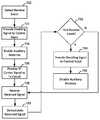
- FIG. 7depicts a non-limiting flow diagram illustrating exemplary methods for wirelessly communicating payment information with a payment device in accordance with some embodiments of the present disclosure.
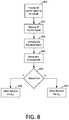
- FIG. 8depicts a non-limiting flow diagram illustrating exemplary steps for improving receive performance of a wireless communication device in accordance with some embodiments of the present disclosure.
- the payment terminalmay have a variety of components for wirelessly communicating payment information with a payment device, such as a near field communications (NFC) system for radio frequency (RF) communications and a card slot with physical and electrical connectivity.
- the payment terminalmay have a transponder antenna for transmitting a RF signal to allow the payment terminal to communicate data wirelessly with a payment device based on a wireless carrier signal transmitted by the payment terminal and inductively coupled with the payment device.
- the payment terminalmay modulate the wireless carrier signal and transmit the modulated wireless signal via the transponder antenna.
- the payment devicemay communicate with the payment terminal by modulating the inductively coupled wireless carrier signal (e.g., while the payment terminal is not modulating the wireless carrier signal). During times that the payment terminal is not modulating the wireless carrier signal, it may utilize an auxiliary antenna that creates additional inductive coupling with the transponder antenna and the antenna of the payment device.
- an auxiliary control circuitmay selectively enable or disable the auxiliary antenna (e.g., based on whether the payment terminal is transmitting or receiving data).
- a control signalmay be provided to a control input of a switching circuit, which may selectively open or close a circuit including the auxiliary antenna and other associated circuitry (e.g., an auxiliary load circuit coupled to the auxiliary antenna).
- the modulated signal from the payment deviceis received by the payment terminal based on changes to the inductively coupled signal, which is coupled to receive circuitry for processing.
- the payment terminalmay have a processing element coupled to the transmit circuit, receive circuit, and control input that is configured to execute various instructions for allowing the payment reader to communicate wirelessly with a payment device.
- the processing elementmay access transmit control instructions, receive control instructions, and receive measurement instructions stored in memory.
- the transmit control instructionsmay cause the processing element to provide the modulated wireless signal to the transmit circuit and to provide the disabling signal to the control input.
- the receive control instructionsmay cause the processing element to provide the wireless carrier signal to the transmit circuit and the enabling signal to the control input.
- the receive measurement instructionsmay cause the processing element to demodulate the received signal during receive events.
- An inductively coupled load that is represented by the received signal during receive eventsmay be based on the auxiliary antenna and the payment device.
- the electronic interactions between the merchant and the customertake place between the customer's payment device 10 and the merchant's payment terminal 20 .
- the customerhas a payment device 10 such as a credit card having magnetic stripe, a credit card having an EMV chip, or a NFC-enabled electronic device such as a smart phone running a payment application.
- the merchanthas a payment terminal 20 such as a payment terminal or other electronic device that is capable of processing payment information (e.g., encrypted payment card data and user authentication data) and transaction information (e.g., purchase amount and point-of-purchase information), such as a smart phone or tablet running a payment application.
- payment informatione.g., encrypted payment card data and user authentication data
- transaction informatione.g., purchase amount and point-of-purchase information
- the initial processing and approval of the payment transactionmay be processed at payment terminal 20 .
- payment terminal 20may communicate with payment server 40 over network 30 .
- payment server 40may be operated by a single entity, in one embodiment payment server 40 may include any suitable number of servers operated by any suitable entities, such as a payment service system 50 and one or more banks of the merchant and customer (e.g., a bank server 60 ).
- the payment terminal 20 and the payment server 40communicate payment and transaction information to determine whether the transaction is authorized.
- payment terminal 20may provide encrypted payment data, user authentication data, purchase amount information, and point-of-purchase information to payment server 40 over network 30 .
- Payment server 40may determine whether the transaction is authorized based on this received information as well as information relating to customer or merchant accounts, and respond to payment terminal 20 over network 30 to indicate whether or not the payment transaction is authorized.
- Payment server 40may also transmit additional information such as transaction identifiers to payment terminal 20 .
- the merchantmay indicate to the customer whether the transaction has been approved.
- approvalmay be indicated at the payment terminal, for example, at a screen of a payment terminal.
- information about the approved transaction and additional informatione.g., receipts, special offers, coupons, or loyalty program information
- additional informationmay be provided to the NFC payment device for display at a screen of the smart phone or watch or storage in memory.
- FIG. 2depicts an illustrative block diagram of payment device 10 and payment terminal 20 in accordance with some embodiments of the present disclosure.
- the payment terminal 20may comprise a payment reader 22 and a merchant device 29 .
- the term payment terminalmay refer to any suitable component of the payment terminal, such as payment reader 22 or merchant device 29 , or any subset of functionality implemented on one or both thereof.
- the payment reader 22 of payment terminal 20may be a wireless communication device that facilitates transactions between the payment device 10 and a merchant device 29 running a point-of-sale application.
- payment device 10may be a device that is capable of communicating with payment terminal 20 (e.g., via payment reader 22 ), such as a NFC device 12 or an EMV chip card 14 .
- Chip card 14may include a secure integrated circuit that is capable of communicating with a payment terminal such as payment terminal 20 , generating encrypted payment information, and providing the encrypted payment information as well as other payment or transaction information (e.g., transaction limits for payments that are processed locally) in accordance with one or more electronic payment standards such as those promulgated by EMVCo.
- Chip card 14may include contact pins for communicating with payment reader 22 (e.g., in accordance with ISO 7816) and in some embodiments, may be inductively coupled to payment reader 22 via a near field 15 .
- a chip card 14 that is inductively coupled to payment reader 22may communicate with payment reader 22 using load modulation of a wireless carrier signal that is provided by payment reader 22 in accordance with a wireless communication standard such as ISO 14443.
- NFC device 12may be an electronic device such as a smart phone, tablet, or smart watch that is capable of engaging in secure transactions with payment terminal 20 (e.g., via communications with payment reader 22 ).
- NFC device 12may have hardware (e.g., a secure element including hardware and executable code) and/or software (e.g., executable code operating on a processor in accordance with a host card emulation routine) for performing secure transaction functions.
- NFC device 12may be inductively coupled to payment reader 22 via near field 15 and may communicate with payment terminal 20 by active or passive load modulation of a wireless carrier signal provided by payment reader 22 in accordance with one or more wireless communication standards such as ISO 14443 and ISO 18092.
- payment terminal 20may be implemented in any suitable manner, in one embodiment payment terminal 20 may include a payment reader 22 and a merchant device 29 .
- the merchant device 29runs a point-of-sale application that provides a user interface for the merchant and facilitates communication with the payment reader 22 and the payment server 40 .
- Payment reader 22may facilitate communications between payment device 10 and merchant device 29 .
- a payment device 10such as NFC device 12 or chip card 14 may communicate with payment reader 22 via inductive coupling. This is depicted in FIG. 2 as near field 15 , which comprises a wireless carrier signal having a suitable frequency (e.g., 13.56 MHz) emitted from payment reader 22 .
- payment device 10may be a contactless payment device such as NFC device 12 or chip card 14 , and payment reader 22 and the contactless payment device 10 may communicate by modulating the wireless carrier signal within near field 15 .
- payment reader 22changes the amplitude and/or phase of the wireless carrier signal based on data to be transmitted from payment reader 22 , resulting in a wireless data signal that is transmitted to the payment device.
- This signalis transmitted by an antenna of payment reader 22 that is tuned to transmit at 13.56 MHz, and if the contactless device also has a suitably tuned antenna within the range of the near field 15 (e.g., 0 to 10 cm), the payment device receives the wireless carrier signal or wireless data signal that is transmitted by payment reader 22 .
- processing circuitry of the contactless deviceis able to demodulate the received signal and process the data that is received from payment reader 22 .
- payment reader 22also includes an EMV slot 21 that is capable of receiving chip card 14 .
- Chip card 14may have contacts that engage with corresponding contacts of payment reader 22 when chip card 14 is inserted into EMV slot 21 .
- Payment reader 22provides power to an EMV chip of chip card 14 through these contacts and payment reader 22 and chip card 14 communicate through a communication path established by the contacts.
- Payment reader 22may also include hardware for interfacing with a magnetic strip card (not depicted in FIG. 2 ).
- the hardwaremay include a slot that guides a customer to swipe or dip the magnetized strip of the magnetic strip card such that a magnetic strip reader can receive payment information from the magnetic strip card. The received payment information is then processed by the payment reader 22 .
- the payment terminal 20 and contactless deviceare typically not constrained in relation to the surfaces of the devices, there may also be a misalignment between the antennas along the planes of those devices (e.g., an x or y misalignment in a three-dimensional space).
- a customermay typically hold the contactless device at an angle relative to payment terminal, resulting in additional variability of the relative distance, position, and orientation of the antennas.
- the packaging of antennas within the payment terminal 20 and device 10may not always place the antennas at the same location relative to the planes of the surfaces of the devices, and materials may impact the operation and effective load of inductively coupled antennas.
- the payment terminal 20may have a transponder antenna and an auxiliary antenna.
- the transponder antennamay transmit the wireless carrier signal, transmit data over a modulated wireless carrier signal, and may receive data via a modulated version of the wireless carrier signal received by inductive coupling.
- the auxiliary antennamay selectively be enabled, at which time it may be inductively coupled with the transponder antenna, which may modify the overall inductive coupling of the inductively coupled components (e.g., transponder antenna and an antenna of the contactless device) in a manner that improves performance within dead zones.
- the payment terminal 20may have an auxiliary control circuit that may enable and disable the auxiliary antenna so that it only receives the RF signal through inductive coupling with the transponder antenna.
- the auxiliary antennamay be positioned within the payment terminal 20 at a fixed location and orientation relative to the transponder antenna (e.g., in parallel to the transponder antenna, and on the opposite side of the transponder antenna from a target region where a user should place a contactless device), it will be understood that the auxiliary antenna may be positioned at any suitable location for coupling with the transponder antenna and performing the functionality of payment terminal 20 described herein.
- Merchant device 29may be in communication with payment reader 22 via a communication path 23 / 25 / 27 .
- communication path 23 / 25 / 27may be implemented via a wired (e.g., Ethernet, USB, FireWire, Lightning) or wireless (e.g., Wi-Fi, Bluetooth, NFC, or ZigBee) connection
- payment reader 22may communicate with the merchant device 29 via a Bluetooth low energy interface, such that the payment reader 22 and the merchant device 29 are connected devices.
- processing of the payment transactionmay occur locally on payment reader 22 and merchant device 29 , for example, when a transaction amount is small or there is no connectivity to the payment server 40 .
- merchant device 29 or payment reader 22may communicate with payment server 40 via a public or dedicated communication network 30 .
- communication network 30may be any suitable communication network, in one embodiment communication network 30 may be the internet and payment and transaction information may be communicated between payment terminal 20 and payment server 40 in an encrypted format such by a transport layer security (TLS) or secure sockets layer (SSL) protocol.
- TLStransport layer security
- SSLsecure sockets layer
- FIG. 3depicts a block diagram of an exemplary payment terminal 20 in accordance with some embodiments of the present disclosure.
- payment terminal 20may be implemented as a payment reader 22 that communicates wirelessly with an interactive electronic device such as a merchant device 29 , for example, using Bluetooth classic or Bluetooth low energy.
- an interactive electronic devicesuch as a merchant device 29
- Bluetooth classic or Bluetooth low energyan interactive electronic device
- FIG. 3it will be understood that payment terminal 20 may include additional components, one or more of the components depicted in FIG. 3 may not be included in payment terminal 20 , and the components of payment terminal 20 may be rearranged in any suitable manner.
- payment terminal 20includes a reader chip 100 , a plurality of payment interfaces (e.g., a contactless interface 102 and a contact interface 104 ), a power supply 106 , a wireless communication interface 108 , a wired interface 110 , a signal conditioning device 112 , and a transaction chip 114 .
- Payment terminal 20also includes a processing unit 120 and memory 122 in reader chip 100 , and general processing unit 124 , cryptographic processing unit 125 , general memory 126 and cryptographic memory 128 in transaction chip 114 .
- reader chip 100may be any suitable chip, such as a K21 chip supplied by Freescale Semiconductor, Inc.
- Processing unit 120 of reader chip 100 of payment terminal 20may be any suitable processor and may include any suitable hardware, software, memory, and circuitry as is necessary to perform and control the functions of payment terminal 20 .
- Processing unit 120may include a number of processors, and may perform the operations of reader chip 100 based on instructions in one or more memories and memory types. In some embodiments, processing unit 120 may have multiple independent processing units, for example a multi-core processor or other suitable component.
- Processing unit 120may execute instructions stored in memory 122 of reader chip 100 to control the operations and processing of payment terminal 20 .
- the processing unit 120 of reader chip 100may include two RISC processors configured to operate as a hub for controlling operations of the various components of payment terminal 20 , based on instructions stored in memory 122 .
- memorymay refer to any suitable tangible or non-transitory storage medium. Examples of a tangible (or non-transitory) storage medium include disks, thumb drives, and memory, etc., but does not include propagated signals. Tangible computer readable storage mediums include volatile and non-volatile, removable and non-removable media, such as computer readable instructions, data structures, program modules or other data. Examples of such media include RAM, ROM, EPROM, EEPROM, SRAM, flash memory, disks or optical storage, magnetic storage, or any other non-transitory medium that stores information that is accessed by a processor or computing device.
- Reader chip 100may also include additional circuitry such as interface circuitry.
- interface circuitrymay include circuitry for interfacing with a wireless communication interface 108 (e.g., Wi-Fi, Bluetooth classic, and Bluetooth low energy), circuitry for interfacing with a wired interface 110 (e.g., USB, Ethernet, FireWire, and Lightning), circuitry for interfacing with other communication interfaces or buses (e.g., I 2 C, SPI, UART, and GPIO), and circuitry for interfacing with a power supply 106 (e.g., power management circuitry, power conversion circuitry, rectifiers, and battery charging circuitry).
- a wireless communication interface 108e.g., Wi-Fi, Bluetooth classic, and Bluetooth low energy
- wired interface 110e.g., USB, Ethernet, FireWire, and Lightning
- other communication interfaces or busese.g., I 2 C, SPI, UART, and GPIO
- power supply 106e.g., power management circuitry, power conversion circuitry, rectifiers,
- Wireless communication interface 108may include any suitable wireless communications hardware (e.g., antennas, matching circuitry, etc.) and one or more processors having processing capability necessary to engage in wireless communication (e.g., with a merchant device 29 via a protocol such as Bluetooth, or directly with a network 30 via a WiFi protocol) and control associated circuitry, including but not limited to hardware logic, computer readable instructions running on a processor, or any suitable combination thereof.
- wireless communication interface 108may be implemented in any suitable manner, in an exemplary embodiment, wireless communication interface 108 may be implemented as a Texas Instruments CC2640 device, which may include a processing unit and memory in some embodiments.
- Power supply 106may include one or more power supplies such as a physical connection to AC power or a battery. Power supply 106 may include power conversion circuitry for converting AC power and generating a plurality of DC voltages for use by components of payment terminal 20 . When power supply 106 includes a battery, the battery may be charged via a physical power connection, via inductive charging, or via any other suitable method. Although not depicted as physically connected to the other components of the payment terminal 20 in FIG. 3 , power supply 106 may supply a variety of voltages to the components of the payment terminal 20 in accordance with the requirements of those components.
- Memory 122 of reader chip 100may include a plurality of sets of instructions for controlling operations of payment terminal 20 , such as operating instructions 130 and transaction processing instructions 132 .
- Operating instructions 130may include instructions for controlling any suitable general operations of the payment terminal 20 , such as internal communications, power management, processing of messages, system monitoring, sleep modes, user interface response and control, operation of the wireless interface 108 , operation of the transaction chip 114 , and the management of the other sets of instructions.
- the operating instructions 130may provide the operating system and applications necessary to perform most of the processing operations that are performed by the processing unit 120 of the reader chip 100 of payment terminal 20 .
- Operating instructions 130may also include instructions for interacting with a merchant.
- payment terminal 20may be running a point-of-sale application.
- the point-of-sale applicationmay provide a user interface that facilitates a user such as a merchant to engage in purchase transactions with a customer. Menus may provide for the selection of items, calculation of taxes, addition of tips, and other related functionality.
- the operating instructions 130facilitate processing of the payment, for example, by acquiring payment information via the contactless interface 102 or contact interface 104 , invoking the transaction chip 114 to process that payment information, and by generating responsive messages that are transmitted to the point-of-sale application of the merchant device 29 via wireless interface 108 .
- aspects of the point-of sale applicationmay run on the merchant device and the operating instructions 130 may include instructions for a complementary application to run on processing unit 120 of reader chip 100 , in order to exchange information with the point-of-sale application.
- the point-of-sale applicationmay send a message to the payment reader 22 (e.g., via wireless interface 108 ).
- Operating instructions 130may also include instructions for interacting with a payment service system 50 at a payment server 40 .
- a payment service system 50may be associated with the payment terminal 20 .
- the payment service system 50may have information about payment terminals 20 that are registered with the payment service system 50 (e.g., based on unique identifiers). This information may be used to process transactions with servers of the merchant and customer financial institutions, for providing analysis and reports to a merchant, and aggregating transaction data.
- the payment terminal 20may process payment information (e.g., based on operation of reader chip 100 and transaction chip 114 ) and communicate that processed payment information to the point-of-sale application, which in turn communicates with the payment service system 50 . In this manner, messages from the payment terminal 20 may be forwarded to the payment service system 50 of payment server 40 , such that the payment terminal 20 and payment service system 50 may collectively process the payment transaction.
- Transaction processing instructions 132may include instructions for processing payment transactions at payment terminal 20 .
- the transaction processing instructionsmay be compliant with a payment standard such as those promulgated by EMV.
- a payment standardsuch as those promulgated by EMV.
- EMVEuropay, Mastercard, Visa, American Express, etc.
- these instructionsmay determine whether to process a transaction locally, how payment information is accessed from a payment device, how that payment information is processed, which cryptographic functions to perform, the types of communications to exchange with a payment server, and any other suitable information related to the processing of payment transactions.
- transaction processing instructions 132may perform high level processing, and provide instructions for processing unit 120 to communicate with transaction chip 114 to perform complex transaction processing and cryptographic operations.
- Transaction chip 114may include one or more processors having processing capability necessary to perform the processing functions described herein, including but not limited to hardware logic, computer readable instructions running on a processor, or any suitable combination thereof. In an exemplary embodiment, transaction chip 114 may perform functionality relating to processing of payment transactions, interfacing with payment devices, cryptography, and other payment-specific functionality. In some embodiments, transaction chip 114 may include a general processing unit 124 for executing instructions associated with general payment functionality and a cryptographic processing unit 125 for handling cryptographic processing operations. Each of general processing unit 124 and cryptographic processing unit 125 may have dedicated memory associated therewith (e.g., general memory 126 and memory such as cryptographic memory 128 ). In this manner, specific cryptographic processing and critical security information (e.g., cryptographic keys, passwords, user information, etc.), may be securely stored and processed by cryptographic memory 128 and cryptographic processing unit 125 .
- specific cryptographic processing and critical security informatione.g., cryptographic keys, passwords, user information, etc.
- general processing unit 124may include any suitable processor for performing the payment processing functionality of payment terminal 20 described herein.
- general memory 126may include a plurality of sets of instructions for performing general transaction processing operations of payment terminal 20 , such as transaction processing instructions 166 , data authentication instructions 168 , and signal conditioning instructions 170 .
- General memory 126also may include instructions for performing wireless NFC communications described herein between the payment terminal 20 and a contactless device, such as transmit control instructions 172 , receive control instructions 173 , and receive measurement instructions 174 .
- Transaction processing instructions 166may include instructions for controlling general transaction processing operations of the payment terminal 20 , such as controlling the interaction between the payment terminal 20 and a payment device 10 (e.g., for interfacing with a payment device via the contactless interface 102 and contact interface 104 ), selecting payment processing procedures (e.g., based on a payment processing entity associated with a payment method), interfacing with the cryptographic processor 125 , and other aspects of transaction processing.
- Data authentication instructions 168may include instructions for providing configuration information for a payment terminal 20 . The configuration information may include such information as payment limits and types of transactions for local transactions (i.e., transactions that occur without contacting a payment server 40 ) and supported applications.
- data authentication instructions 168may include configuration instructions such as TMS-CAPK instructions.
- the TMS-CAPKmay be tailored for a particular jurisdiction (e.g., country-specific).
- Signal conditioning instructions 170may include instructions for interacting with signal conditioning device 112 , including instructions for conditioning signals received from a contactless device via the contactless interface 102 (e.g., from a NFC payment device 10 ). Although in some embodiments, signal conditioning instructions 170 may include instructions for manipulating signals received via contactless interface 102 , wherein the signal conditioning device 112 is a field programmable gate array (FPGA), in other embodiments, signal conditioning instructions 170 may include instructions for conditioning signals using any suitable hardware, logic, or algorithm required to process NFC signals received via contactless interface 102 .
- FPGAfield programmable gate array
- Transmit control instructions 172may include instructions for determining an occurrence of an event for which transmission of a modulated wireless signal may be desired and enabling the general processing unit 124 to wirelessly communicate with a contactless device.
- transmit control instructions 172may include instructions for providing a wireless carrier signal to the transponder antenna of the contactless interface 102 of payment terminal 20 and selectively modulating the wireless carrier signal (e.g., by adjusting a load applied to the transponder antenna).
- Receive control instructions 173may include instructions for receiving and processing a modulated version of the wireless carrier signal received at the transponder antenna of the contactless interface 102 (e.g., from a contactless device), and selectively providing a control signal to a control input of an auxiliary circuit within the payment terminal 20 in order to selectively enable an auxiliary antenna of the contactless interface.
- Receive measurement instructions 174may include instructions for demodulating a received modulated version of the wireless carrier signal received based on inductive coupling of the payment terminal 20 and a contactless device.
- cryptographic memory 128may be a memory or combination thereof as described herein, and may include a plurality of sets of instructions for performing cryptographic operations, such as payment processing instructions 176 and cryptographic instructions 178 .
- Payment processing instructions 176may include instructions for performing aspects of payment processing, such as providing for encryption techniques to be used in association with particular payment procedures, accessing account and processing information, any other suitable payment processing functionality, or any suitable combination thereof.
- Cryptographic instructions 178may include instructions for performing cryptographic operations.
- Cryptographic processing unit 125may execute the cryptographic instructions 178 to perform a variety of cryptographic functions, such as to encrypt, decrypt, sign, verify signatures, and process transaction information as part of a payment transaction.
- signal conditioning device 112may include any suitable hardware, software, or any combination thereof, in an exemplary embodiment signal conditioning device may comprise an FPGA. Signal condition device 112 may receive and condition signals sent from contactless interface 102 , such as when a contactless device using NFC communication communicates with payment terminal 20 . In an embodiment, signal conditioning device 112 may operate based on instructions stored at transaction chip 114 (e.g., signal conditioning instructions 170 ) for use in interacting with the contactless interface 102 .
- instructions stored at transaction chip 114e.g., signal conditioning instructions 170
- Contactless interface 102may provide for NFC communication with a contactless device such as NFC device 12 or chip card 14 .
- a contactless devicesuch as NFC device 12 or chip card 14 .
- an antenna of contactless interface 102such as a transponder antenna, may output either a carrier signal or a modulated signal.
- a carrier signalmay be a signal having a fixed frequency such as 13.56 MHz.
- a modulated signalmay be a modulated version of the carrier signal according to a modulation procedure such as ISO 14443 and ISO 18092.
- the contactless devicemay also modulate the carrier signal, which may be sensed by the contactless interface 102 and provided to the transaction chip 114 for processing.
- the contactless interface 102may also include an auxiliary antenna and auxiliary circuit.
- the auxiliary antennamay be selectively enabled in order to modify the inductive coupling of the transponder antenna to a contactless device such as a contactless payment device 10 , for example, during periods of operation in which the payment terminal 20 is not transmitting a modulated signal.
- some or all of the components of the auxiliary circuitmay be included within the transaction chip 114 , for example, as analog front end circuitry.
- Contact interface 104may be a suitable interface for providing power to a payment chip such as an EMV chip of a chip card 14 and communicating with the EMV chip.
- Contact interface 104may include a plurality of contact pins (not depicted in FIG. 3 ) for physically interfacing with the chip card 14 according to EMV specifications.
- contact interface 104may include a power supply (VCC) pin, a ground (GND) pin, a reset (RST) pin for resetting an EMV card, a clock (CLK) pin for providing a clock signal, a programming voltage (VPP) pin for providing a programming voltage to an EMV card, an input output (I/O) pin for providing for EMV communications, and two auxiliary pins.
- VCCpower supply
- GDDground
- RSTreset
- CLKclock
- VPPprogramming voltage
- I/Oinput output
- FIG. 4depicts an exemplary transaction chip 114 and contactless interface 102 of a payment terminal 20 in accordance with some embodiments of the present disclosure. Although particular components are depicted in a particular arrangement in FIG. 4 , it will be understood that the transaction chip 114 and contactless interface 102 may include additional components, one or more of the components depicted in FIG. 4 may not be included, and the components depicted in FIG. 4 may be rearranged in any suitable manner.
- Transaction chip 114may include hardware, software, memory, and circuitry as described herein, and in an embodiment, is in communication with contactless interface 102 via a plurality of pins such as a positive transmit pin (T XP ), negative transmit pin (T XN ), receive pin (R X ), and an auxiliary control signal (Control).
- Transmit pins T XP and T XNmay provide a transmit signal having a power, amplitude, frequency, phase, and waveform that enable the wireless carrier signal and modulated wireless signal to be transmitted from an antenna 440 of contactless interface 102 .
- the transmit signalmay be provided to the antenna 440 via EMC circuit 420 and matching circuit 430 .
- the transaction chipmay include additional outputs that provide signals to generate the modulated wireless signal (e.g., by controlling a load of contactless interface 102 ) or adjust other signal characteristics such as transmit power (e.g., based on providing a signal to power control circuitry such as an H-Bridge of contactless interface 102 ).
- EMC circuit 420may include an electromagnetic interference (EMI) filter for suppressing interference experienced at contactless interface 102 , and may include one or more components such as inductor 422 and capacitor 424 in order to provide acceptable electromagnetic compatibility with other high-frequency signals.
- the output of EMC circuit 420may be provided to matching circuit 430 .
- Matching circuit 430may include suitable components such as resistors, inductors, and capacitors to provide for impedance matching and tuning of transponder antenna 440 .
- matching circuit 430includes a pair of capacitors 424 , but matching circuit 430 may include any suitable components in other embodiments.
- transmit pins T XP and T XNmay output either a wireless carrier signal or a modulated wireless signal.
- a wireless carrier signalmay be a signal having a fixed frequency such as 13.56 MHz.
- Components of EMC circuit 420 and matching circuit 430e.g., resistors, inductors, and capacitors) modify the output waveform of the wireless carrier signal.
- a first portion of the transmit circuitthus couples the output of the T XP pin to a first terminal of transponder antenna 440 while a second portion of the transmit circuit couples the output of the T XN pin to a second terminal of transponder antenna 440 .
- the wireless carrier signalis then transmitted over transponder antenna 440 .
- a modulated wireless signalis output from the antenna.
- the modulated wireless signalvaries from the wireless carrier signal in its amplitude, phase, or both in response to a data signal.
- transaction chip 114may implement a modulation procedure in order to generate the modulated wireless signal, either alone or in combination with modulation circuitry.
- This modulated wireless signalis provided to the transmit circuit and transmitted over antenna 440 as a modulated wireless signal (representing data to be transmitted) during a transmit event.
- Transaction chip 114monitors the signal at transponder antenna 440 through receive pin R X .
- the receive pin R Xis coupled to a receive circuit, which in an embodiment may include signal conditioning device 112 and/or other circuitry (e.g., matching circuitry) and which may be coupled to a second terminal of transponder antenna 440 through this circuitry.
- transaction chip 114may monitor what is being transmitted (e.g., the wireless carrier signal and modulated wireless signal) as well as changes that are applied to the wireless carrier signal by a contactless payment device 10 such as NFC device 12 or chip card 14 .
- a period during which the transaction chip 114 monitors for a signal that results from modulation of the wireless carrier signal by another devicemay be referred to as a receive event. Based on these modulations of this received signal, transaction chip 114 is able to receive communications from the contactless payment device 10 .
- the transponder antenna 440transmits the wireless carrier signal while the auxiliary antenna is enabled, the overall inductive loading of the magnetic circuit (e.g., including the transponder antenna 440 , an antenna of a contactless payment device 10 , the auxiliary antennas, and loads associated with each of these antennas) is changed.
- the overall inductive loading of the magnetic circuite.g., including the transponder antenna 440 , an antenna of a contactless payment device 10 , the auxiliary antennas, and loads associated with each of these antennas
- Transaction chip 114may execute instructions stored in memory 126 (e.g., transmit control instructions 172 and receive control instructions 173 ) to provide enabling and disabling signals (e.g., different levels of a signal that cause the antenna to be enabled or disabled) to the switching circuit (e.g., the gate of MOSFET 464 ) for enabling or disabling the auxiliary antenna 460 .
- transaction chip 114may execute transmit control instructions 172 (e.g., using processing unit 124 ) during a transmit event to provide a disabling signal to the switching circuit at the control input.
- the switching circuitmay disable the auxiliary antenna 460 in response to a disabling control signal from transaction chip 114 (i.e., so that it cannot couple with the transponder antenna 440 ).
- transaction chip 114may execute receive control instructions 173 (e.g., using processing unit 124 ) during a receive event to provide an enabling signal to the switching circuit at the control input.
- the switching circuitmay enable the auxiliary antenna 460 in response to an enabling signal at the control input from transaction chip 114 (i.e., so that it couples with the transponder antenna 440 ).
- FIG. 5depicts circuit diagram of an exemplary transaction chip 114 and contactless interface 102 in accordance with some embodiments of the present disclosure. Although particular components are depicted in a particular arrangement in FIG. 5 , it will be understood that transaction chip 114 and contactless interface 102 may include additional components, one or more of the components depicted in FIG. 5 may not be included, and the components of may be rearranged in any suitable manner. In an embodiment, the transaction chip 114 and contactless interface 102 of FIG. 5 may include a number of components that operate in a similar manner as similarly labeled and numbered components of FIG. 4 , such as EMC circuit 420 , matching circuit 430 , transponder antenna 440 , signal conditioning circuit 112 , transmit pin (T XP ), and negative transmit pin (T XN ).
- transaction chip 114 of payment terminal 20may include two receive pins (R X1 and R X2 ).
- the receive pins R X1 and R X2are coupled at different points relative to transponder antenna 440 , EMC circuit 420 , and matching circuitry 430 .
- Receive performance at the payment terminal 20may be improved by selecting between R X1 and R X2 as a source of the received signal.
- transaction chip 114may select between R X1 and R X2 (or in some embodiments, select weightings to be applied to the signals received at R X1 and R X2 ) based on the characteristics of the received signals, based on a particular mode of operation of the payment terminal 20 (e.g., modulation procedure, type of contactless device, etc.), or based on one or more other measured values (e.g., a signal strength, distance, modulation index, etc.), as determined by a measurement circuit (not depicted).
- transaction chip 114may observe electrical characteristics of the transponder antenna or inductively coupled signal (e.g., transmit power, receive power, amplitude, phase, impedance) to determine an estimate of a distance between a target area of the payment terminal 20 and a contactless device and compare the distance with a pre-defined threshold. Transaction chip 114 may then select a receive pin to use for data processing based on the comparison. By processing signals based on only the selected receive pin, transaction chip 114 may better and monitor and demodulate a received signal from a contactless device.
- electrical characteristics of the transponder antenna or inductively coupled signale.g., transmit power, receive power, amplitude, phase, impedance
- the transponder antenna 440may include a plurality of portions arranged in series, such that different tap points may be used to acquire different signal.
- transponder antenna 440 portionsmay be arranged in any suitable manner, in an embodiment, transponder antenna 440 may include a transmit portion 442 and receive portion 444 that are arranged in series.
- each portionmay include one or more square loops on a common plane, with a subset of the loops (e.g., the loops of the receive portion 444 as depicted in FIG. 6 ) located inside of the other loops, although other configurations for looped antenna portions (e.g., on multiple planes, different loop configurations, etc.) may be implemented in other embodiments.
- FIG. 6it will be understood that transponder antenna may include different shapes (e.g., circular, hexagon, etc.) and that the shape need not be symmetric.
- a plurality of receive tap pointsmay be provided at different portions of the transponder antenna 440 .
- multiple tap pointsmay be located at multiple locations of transponder antenna 440
- two receive taps R X1C and R X2Cmay be located to receive the signal from the transmit portion 442 and receive portion 444 , respectively.
- transaction chip 114may selectively monitor at different points of the overall transponder antenna 440 , for example, based on a mode of the payment terminal and/or measured characteristics as described herein.
- FIG. 7depicts a non-limiting flow diagram illustrating exemplary methods for wirelessly communicating payment information with a payment device based on inductive coupling of a radio frequency (RF) signal that is transmitted by the payment terminal in accordance with some embodiments of the present disclosure.
- RFradio frequency
- the wireless communicationmay be NFC communication
- the wireless communication devicemay be a payment terminal 20
- the payment devicemay be a contactless payment device 10 .
- payment terminal 20may determine that a receive event based on processing unit 124 of transaction chip 114 executing receive control instructions 173 .
- a receive eventmay be an event in which a received signal is received by transmit circuit of payment terminal 20 that is indicative of modulation of a wireless carrier signal, such as modulation of the wireless carrier signal by a contactless payment device 10 .
- payment terminal 20may determine that a receive event is occurring whenever data is not being transmitted by payment terminal 20 (e.g., at times other than transmit events). Once transaction chip 114 has detected an occurrence of a receive event, processing may continue to step 722 .
- transaction chip 114may provide an enabling signal to the control input based on processing unit 124 of transaction chip 114 executing receive control instructions 173 . As described herein, processing unit 124 may execute receive control instructions 173 in response to detection of a receive event at the payment terminal 20 . After transaction chip 114 provides the enabling signal to the control input, processing may continue to step 724 .
- a switching circuit of payment terminal 20may enable auxiliary antenna 460 in response to an enabling signal at the control input.
- the switching circuitmay be coupled to auxiliary antenna 460 and the control pin of transaction chip 114 , and may enable the auxiliary antenna 460 .
- Auxiliary antenna 460may be positioned at a location and orientation relative to the transponder antenna 440 that permits inductive coupling of a load represented by a received signal.
- transaction chip 114may provide a wireless carrier signal to a transmit circuit of payment terminal 20 based on processing unit 124 executing receive control instructions 173 .
- the transmit circuit of payment terminal 20may be coupled to the transponder antenna 440 . After the wireless carrier signal has been provided to the transmit circuit, processing may continue to step 728 .
- the receive circuit of payment terminal 20may output a receive signal to transaction chip 114 representing an inductively coupled load that modulates the wireless carrier signal.
- receive circuitmay output to the transaction chip 114 a received signal based on modulation of the wireless carrier signal provided to the transponder antenna 440 at step 726 .
- the received signal output by the receive circuitrepresents an inductively coupled a load for the wireless carrier signal that is based on auxiliary antenna 460 and modulations created at an antenna of contactless payment device 10 (e.g., by a load of the contactless payment device 10 ).
- the inductively coupled loadenables payment terminal 20 to communicate receive data from payment device 10 via transponder antenna 440 and auxiliary antenna 460 .
- processingmay continue to step 730 .
- transaction chip 114may demodulate the received signal based on the processing unit 124 executing receive measurement instructions 174 .
- Processing circuitry of transaction chip 114such as processing unit 124 may receive and demodulate the wireless carrier signal received from contactless payment device 10 and provide data for use by other resources of payment terminal 20 based on the demodulated received signal. After the processing unit 124 demodulates the received signal based on receive measurement instructions 174 , processing may continue to step 732 .
- transaction chip 114may determine whether the receive event has ended based on processing unit 124 executing receive measurement instructions 174 .
- Processing unit 124may execute measurement instructions 174 to process the data represented by the demodulated received signal and determine whether the receive event has ended. If processing unit 124 determines that the receive event has ended, processing may continue to step 734 . If processing unit 124 determines that the receive event has not ended, processing may return to step 728 .
- the switching circuitmay disable the auxiliary antenna in response to a disabling signal provided to the control input by processing unit 124 of transaction chip 114 executing transmit control instructions 172 .
- the control input of the switching circuit of NFC circuit 400may be coupled to auxiliary antenna 460 and control pin of transaction chip 114 , and may disable the auxiliary antenna 460 . Once the transaction chip 114 has disabled the auxiliary antenna 460 , processing may end.
- FIG. 8depicts a non-limiting flow diagram illustrating exemplary steps for modifying a receive path for a wireless communication device in accordance with some embodiments of the present disclosure.
- transaction chip 114provides a wireless carrier signal to transmit circuit of NFC circuit 500 based on processing unit 124 executing receive control instructions 173 .
- the transmit circuit of payment terminal 20may be coupled to the transponder antenna 440 . After the wireless carrier signal has been provided to the transmit circuit, processing may continue to step 822 .
- a modulated version of the wireless carrier signalmay be received based on load modulation produced by a contactless payment device 10 .
- the inductively coupled loadenables payment terminal 20 to communicate data with contactless payment device 10 via transponder antenna 440 , based also on the inductive loading of auxiliary antenna 460 .
- transaction chip 114may receive a received signal that represents an inductively coupled a load for the wireless carrier signal based on auxiliary antenna 460 and the changing load of the contactless payment device 10 . After the received signal is received, processing may continue to step 824 .
- transaction chip 114may demodulate the received signal based on the processing unit 124 executing receive measurement instructions 174 .
- Processing circuitry of transaction chip 114such as processing unit 124 may receive and demodulate the received signal and provide data for use by other resources of payment terminal 20 based on the demodulated received signal. After the processing unit 124 demodulates the received signal based on receive measurement instructions 174 , processing may continue to step 826 .
- transaction chip 114may determine a characteristic of the payment terminal and/or the inductively coupled signal (e.g., an operating mode, a determined characteristic, and/or a measured characteristic) based on the processing unit 124 executing receive measurement instructions 174 .
- Receive measurement instructions 174may include instructions for determining the characteristic (i.e., applied by contactless payment device 10 ), such as by identifying a modulation procedure or measuring an inductively coupled load represented by the received signal from transponder antenna 440 . After transaction chip 114 determines the characteristic, processing may continue to step 828 .
- transaction chip 114may compare the determined characteristic determined at step 826 with a pre-defined criteria (e.g., a threshold) based on the processing unit 124 executing receive measurement instruction.
- receive measurement instructions 174may include the criteria information and may be stored in memory 126 of transaction chip 114 . If transaction chip 114 determines that the determined characteristic meets the criteria (e.g., is greater than a threshold) processing may continue to step 830 , at which transaction chip 114 may select a receive pin R X1 based on the processing unit 124 executing receive control instructions 173 .
- transaction chip 114determines that the determined characteristic does not meet the criteria (e.g., is less than the threshold)
- processingmay continue to step 832 , at which transaction chip 114 may select a receive pin coupled to an EMI filter of EMC circuit 420 based the processing unit 124 executing receive control instructions 173 .
Landscapes
- Engineering & Computer Science (AREA)
- Computer Networks & Wireless Communication (AREA)
- Signal Processing (AREA)
- Business, Economics & Management (AREA)
- Accounting & Taxation (AREA)
- Strategic Management (AREA)
- Physics & Mathematics (AREA)
- General Business, Economics & Management (AREA)
- General Physics & Mathematics (AREA)
- Theoretical Computer Science (AREA)
- Cash Registers Or Receiving Machines (AREA)
- Near-Field Transmission Systems (AREA)
Abstract
Description
Claims (32)
Priority Applications (5)
| Application Number | Priority Date | Filing Date | Title |
|---|---|---|---|
| US15/176,589US10937019B2 (en) | 2016-06-08 | 2016-06-08 | Wireless communication system with auxiliary antenna |
| CN201780035862.XACN109314545B (en) | 2016-06-08 | 2017-06-08 | Wireless communication system with auxiliary antenna |
| EP17739748.6AEP3469721A1 (en) | 2016-06-08 | 2017-06-08 | Wireless communication systems with auxiliary antenna |
| PCT/US2017/036473WO2017214349A1 (en) | 2016-06-08 | 2017-06-08 | Wireless communication systems with auxiliary antenna |
| US17/094,746US11748739B2 (en) | 2016-06-08 | 2020-11-10 | Wireless communication system with auxiliary antenna |
Applications Claiming Priority (1)
| Application Number | Priority Date | Filing Date | Title |
|---|---|---|---|
| US15/176,589US10937019B2 (en) | 2016-06-08 | 2016-06-08 | Wireless communication system with auxiliary antenna |
Related Child Applications (1)
| Application Number | Title | Priority Date | Filing Date |
|---|---|---|---|
| US17/094,746ContinuationUS11748739B2 (en) | 2016-06-08 | 2020-11-10 | Wireless communication system with auxiliary antenna |
Publications (2)
| Publication Number | Publication Date |
|---|---|
| US20170357961A1 US20170357961A1 (en) | 2017-12-14 |
| US10937019B2true US10937019B2 (en) | 2021-03-02 |
Family
ID=59337840
Family Applications (2)
| Application Number | Title | Priority Date | Filing Date |
|---|---|---|---|
| US15/176,589Expired - Fee RelatedUS10937019B2 (en) | 2016-06-08 | 2016-06-08 | Wireless communication system with auxiliary antenna |
| US17/094,746ActiveUS11748739B2 (en) | 2016-06-08 | 2020-11-10 | Wireless communication system with auxiliary antenna |
Family Applications After (1)
| Application Number | Title | Priority Date | Filing Date |
|---|---|---|---|
| US17/094,746ActiveUS11748739B2 (en) | 2016-06-08 | 2020-11-10 | Wireless communication system with auxiliary antenna |
Country Status (4)
| Country | Link |
|---|---|
| US (2) | US10937019B2 (en) |
| EP (1) | EP3469721A1 (en) |
| CN (1) | CN109314545B (en) |
| WO (1) | WO2017214349A1 (en) |
Families Citing this family (11)
| Publication number | Priority date | Publication date | Assignee | Title |
|---|---|---|---|---|
| US11347949B2 (en)* | 2005-05-06 | 2022-05-31 | Mynette Technologies, Inc. | Cellular device including inductive antenna |
| US11023878B1 (en) | 2015-06-05 | 2021-06-01 | Square, Inc. | Apparatuses, methods, and systems for transmitting payment proxy information |
| US10937019B2 (en) | 2016-06-08 | 2021-03-02 | Square, Inc. | Wireless communication system with auxiliary antenna |
| US10318953B2 (en) | 2016-06-29 | 2019-06-11 | Square, Inc. | Near field communication flex circuit |
| US10594599B2 (en) | 2016-08-26 | 2020-03-17 | Cisco Technology, Inc. | Fibre channel fabric slow drain mitigation |
| US10949189B2 (en) | 2017-06-28 | 2021-03-16 | Square, Inc. | Securely updating software on connected electronic devices |
| US10635820B1 (en) | 2017-09-29 | 2020-04-28 | Square, Inc. | Update policy-based anti-rollback techniques |
| US11182770B1 (en)* | 2018-12-12 | 2021-11-23 | Square, Inc. | Systems and methods for sensing locations of near field communication devices |
| CN110580785B (en)* | 2019-01-18 | 2022-05-17 | 深圳市阿尔丰科技有限公司 | Cash register system, cash register device and cash register method applied to cash register system |
| EP3937388A1 (en)* | 2020-07-10 | 2022-01-12 | STMicroelectronics Austria GmbH | Near-field communications circuit |
| CN117374613A (en)* | 2022-03-10 | 2024-01-09 | 荣耀终端有限公司 | Wireless communication device and control method thereof |
Citations (176)
| Publication number | Priority date | Publication date | Assignee | Title |
|---|---|---|---|---|
| US3128349A (en) | 1960-08-22 | 1964-04-07 | Bell Telephone Labor Inc | Multifrequency signal receiver |
| US4776003A (en) | 1986-10-01 | 1988-10-04 | Harris Arlene J | Cellular mobile radio credit card system |
| US4860336A (en) | 1987-06-02 | 1989-08-22 | Motorola, Inc. | Radiotelephone credit card data communications |
| US5221838A (en) | 1990-12-24 | 1993-06-22 | Motorola, Inc. | Electronic wallet |
| US5351296A (en) | 1993-03-29 | 1994-09-27 | Niobrara Research & Development Corporation | Financial transmission system |
| US5388155A (en) | 1992-08-07 | 1995-02-07 | Smith; William G. | Cordless phone holder enabling hands free use |
| US5408513A (en) | 1993-09-24 | 1995-04-18 | Busch, Jr.; Charles | Portable credit card terminal interface |
| JPH09231285A (en) | 1996-02-22 | 1997-09-05 | Masao Yoshida | Multimedia home electronic settlement terminal device |
| US5714741A (en) | 1995-04-28 | 1998-02-03 | Koninklijke Ptt Nederland N.V. | Device for transparent interaction between an IC card and a remote terminal |
| US5729591A (en) | 1994-08-15 | 1998-03-17 | Bailey; Ken | Credit card operated cellular phone |
| WO1998012674A2 (en) | 1996-09-20 | 1998-03-26 | Wave Holdings Limited | Pocket value terminal |
| US5740232A (en) | 1994-05-06 | 1998-04-14 | France Telecom | Smart card based system for telephone-securized transactions |
| US5838773A (en) | 1995-08-08 | 1998-11-17 | Belco Systems Technology Corp. | Personal reader capture transfer technology |
| US5850599A (en) | 1992-09-25 | 1998-12-15 | Ecs Enhanced Cellular Systems Manufacturing Inc. | Portable cellular telephone with credit card debit system |
| US5867795A (en) | 1996-08-23 | 1999-02-02 | Motorola, Inc. | Portable electronic device with transceiver and visual image display |
| EP0895203A2 (en) | 1997-07-30 | 1999-02-03 | Hagenuk Gmbh | Card terminal shaped device |
| KR19990066397A (en) | 1998-01-26 | 1999-08-16 | 유영식 | Data conversion device between credit card inquiry and mobile communication terminal |
| US5940510A (en) | 1996-01-31 | 1999-08-17 | Dallas Semiconductor Corporation | Transfer of valuable information between a secure module and another module |
| KR19990068618A (en) | 1999-06-07 | 1999-09-06 | 정장호 | Method for financial transaction using a mobile commnication network and system for performing the same |
| US6010067A (en) | 1994-01-25 | 2000-01-04 | Dynamic Data Systems Pty. Ltd. | Mobile funds transaction device for transferring funds between remote banking facilities |
| JP2000030146A (en) | 1998-03-05 | 2000-01-28 | Keycorp Ltd | Mobile electronic paying terminal |
| WO2000011624A1 (en) | 1998-08-25 | 2000-03-02 | Telefonaktiebolaget Lm Ericsson (Publ) | Smart card wallet |
| WO2000025277A1 (en) | 1998-10-26 | 2000-05-04 | Bell Canada | Portable smart card reader and transaction system |
| US6098881A (en) | 1998-07-22 | 2000-08-08 | Mag-Tek, Inc. | Magnetic stripe card verification system |
| JP2000276539A (en) | 1999-03-25 | 2000-10-06 | Capion:Kk | Card payment method for mobile terminal using PHS (registered trademark) and mobile communication |
| US6144336A (en) | 1997-05-19 | 2000-11-07 | Integrated Data Communications, Inc. | System and method to communicate time stamped, 3-axis geo-position data within telecommunication networks |
| KR200225019Y1 (en) | 2001-01-08 | 2001-05-15 | 주식회사이지엘 | Apparatus of card check that use mobile communication terminal |
| US6234389B1 (en) | 1998-04-29 | 2001-05-22 | @Pos.Com, Inc. | PCMCIA-based point of sale transaction system |
| JP2001222595A (en) | 2000-02-08 | 2001-08-17 | Mitsubishi Electric Corp | Payment system and payment method |
| US6278779B1 (en) | 1998-06-19 | 2001-08-21 | Siemens Information And Communication Networks, Inc. | Telephone shoulder rest and stand |
| WO2001086599A2 (en) | 2000-04-14 | 2001-11-15 | Supercom Ltd. | Smart communications |
| FR2812744A1 (en) | 2000-08-04 | 2002-02-08 | Dassault Automatismes | ELECTRONIC PAYMENT DEVICE USING A CONSUMER APPARATUS AND A COMMERCIAL APPARATUS COMMUNICATING THROUGH A WIRELESS LINK |
| FR2812745A1 (en) | 2000-08-04 | 2002-02-08 | Dassault Automatismes | Vendor electronic payment terminal using a mobile phone as a modem so that the payment terminal cost is greatly reduced as it is greatly simplified and does not require a GSM communications facility |
| JP2002074507A (en) | 2000-08-24 | 2002-03-15 | Com'app:Kk | Electronic contract system, contract data preparing device and information communication terminal |
| US6360362B1 (en) | 1998-02-20 | 2002-03-19 | Intel Corporation | Automatic update of camera firmware |
| WO2002033669A1 (en) | 2000-10-18 | 2002-04-25 | Ultra Proizvodnja Elektronskih Naprav D.O.O. | System for payment data exchange and payment terminal device used therein |
| JP2002123771A (en) | 2000-10-17 | 2002-04-26 | Jcb:Kk | Ic card and method for charging electronic money to the same |
| WO2002043020A2 (en) | 2000-11-22 | 2002-05-30 | Horizonte Venture Management Gmbh | Method and device for the transmission of data by mobile telephone in cashless electronic payments |
| US20020091633A1 (en) | 2001-01-10 | 2002-07-11 | Integrated Data Communications | Facility and method for cellular data communication between merchants and credit processing agencies |
| JP2002279320A (en) | 2001-03-15 | 2002-09-27 | Kenwood Corp | Method and device for settling by credit by mobile phone |
| WO2002082388A1 (en) | 2001-04-06 | 2002-10-17 | Gemplus | Secure data exchange device |
| US20020153414A1 (en) | 1999-08-09 | 2002-10-24 | First Data Corporation | Systems and methods for performing transactions at a point-of-sale |
| WO2002084548A1 (en) | 2001-04-11 | 2002-10-24 | Eleven Point Two Inc | Electronic settling system |
| US6481623B1 (en) | 1998-08-03 | 2002-11-19 | Privicom, Inc. | Card reader for transmission of data by sound |
| EP1260947A1 (en) | 2001-05-17 | 2002-11-27 | Lipman Electronic Engineering Ltd. | Improved wireless point-of-sale terminal |
| JP2002352166A (en) | 2001-05-29 | 2002-12-06 | Seiko Instruments Inc | System and terminal for authenticating credit card |
| JP2002358285A (en) | 2001-05-31 | 2002-12-13 | Adc Technology Kk | Authentication system and authentication method |
| KR20030005984A (en) | 2001-07-11 | 2003-01-23 | 함한경 | Card reading machine for multifunction |
| KR20030005936A (en) | 2001-07-11 | 2003-01-23 | 함한경 | card checking machine for mobile phone |
| KR20030012910A (en) | 2003-01-08 | 2003-02-12 | (주)아이엠넷피아 | Method for electronic settlement using mobile phone |
| JP2003108777A (en) | 2001-09-28 | 2003-04-11 | Glory Ltd | Method, device for informing settlement information, settlement information managing device and program |
| US20030076263A1 (en)* | 2001-10-24 | 2003-04-24 | Datamars Sa | Identifying assembly comprising an interrogator and a transponder |
| WO2003044710A1 (en) | 2001-10-11 | 2003-05-30 | Trustcopy Pte Ltd | Apparatus, method and system for payment using a mobile device |
| FR2834156A1 (en) | 2001-12-20 | 2003-06-27 | Gemplus Card Int | Service access system uses wireless network chip card reader and mobile phone |
| US20030135418A1 (en) | 2002-01-11 | 2003-07-17 | Swetank Shekhar | Point-of-sale (POS) systems that use a peripheral device for point-of-sale applications and methods of operating the same |
| US20030154414A1 (en) | 2002-02-12 | 2003-08-14 | Clay Von Mueller | Magnetic stripe reader for PDA attachment and method of making same |
| US20030183691A1 (en) | 2001-02-08 | 2003-10-02 | Markku Lahteenmaki | Smart card reader |
| JP2003281453A (en) | 2002-03-20 | 2003-10-03 | Matsushita Electric Ind Co Ltd | Product receiving system |
| JP2003308438A (en) | 2002-04-16 | 2003-10-31 | Seiko Instruments Inc | Card settlement system and card settlement method |
| KR200333809Y1 (en) | 2003-08-20 | 2003-11-17 | 나이스정보통신주식회사 | terminal for inquiring of credit card for mobile phone |
| US20040012875A1 (en) | 1999-03-01 | 2004-01-22 | Wood Stephen R. | Magnetic read head having decode circuitry |
| JP2004054651A (en) | 2002-07-22 | 2004-02-19 | Seiko Instruments Inc | Card settlement system using portable telephone, card settlement method using portable telephone, settlement information processing device, settlement information processing method, settlement information processing program, and storage medium with settlement information processing program stored |
| KR20040016548A (en) | 2002-08-17 | 2004-02-25 | 안지영 | Wireless credit card payment system and method using card checker and mobile communication terminals with short distance wireless communication function |
| JP2004062733A (en) | 2002-07-31 | 2004-02-26 | Seiko Instruments Inc | Card settlement terminal registering system, apparatus, method, and program for processing user registering information, and storage medium for storing user registering information processing program |
| US20040041911A1 (en) | 2000-02-29 | 2004-03-04 | Kyocera Corporation | Portable information terminal and digital camera for portable information terminal and portable digital camera/information terminal system |
| JP2004078553A (en) | 2002-08-19 | 2004-03-11 | Seiko Instruments Inc | Card settlement system and terminal device, encryption method and program for card settlement data, and storage medium storing program |
| JP2004078662A (en) | 2002-08-20 | 2004-03-11 | Seiko Instruments Inc | Card settlement system, method, terminal device, information processing device and program, and recording medium storing card settlement program |
| WO2004023366A1 (en) | 2002-09-03 | 2004-03-18 | Smartint Co., Ltd. | System for electronically settling by using mobile phone and method thereof |
| US20040059682A1 (en) | 2001-06-11 | 2004-03-25 | Yoshitsugu Hasumi | Electronic commercial transaction support method |
| DE20320080U1 (en) | 2003-12-23 | 2004-04-15 | E-Prompt Germany Commercial Services Gmbh | Card reader for mobile equipment such as a telephone, uses an infra red or Bluetooth link |
| JP2004199405A (en) | 2002-12-18 | 2004-07-15 | Nec Corp | Settlement system, settlement information processor, and settlement information processing method and program |
| US20040159699A1 (en) | 2003-02-19 | 2004-08-19 | First Data Corporation | Peripheral point-of-sale systems and methods of using such |
| US20040167820A1 (en) | 2003-02-26 | 2004-08-26 | Diana Melick | Two part payment terminal |
| KR100447431B1 (en) | 2004-03-15 | 2004-09-07 | (주)엠씨페이 | a wireless credit card settle accounting apparatus |
| US20040204082A1 (en) | 2003-01-07 | 2004-10-14 | International Business Machines Corporation | Mobile financial card scanner using a wireless digital network to transmit the transaction of the purchase of goods and services |
| US6886742B2 (en) | 1999-08-09 | 2005-05-03 | First Data Corporation | Systems and methods for deploying a point-of sale device |
| US20050097015A1 (en) | 2003-10-30 | 2005-05-05 | Wilkes W. B. | Electronic financial transactions with portable merchant accounts |
| US20050108444A1 (en) | 2003-11-19 | 2005-05-19 | Flauaus Gary R. | Method of detecting and monitoring fabric congestion |
| US20050109841A1 (en) | 2003-11-17 | 2005-05-26 | Ryan Dennis J. | Multi-interface compact personal token apparatus and methods of use |
| CN1630988A (en) | 2002-04-23 | 2005-06-22 | 株式会社村田制作所 | Wireless communication RF circuit and communication apparatus including the same |
| US20050236480A1 (en) | 2004-04-23 | 2005-10-27 | Virtual Fonlink, Inc. | Enhanced system and method for wireless transactions |
| KR200405877Y1 (en) | 2005-10-21 | 2006-01-11 | 안지영 | Portable Card Size |
| US6990683B2 (en) | 2000-04-28 | 2006-01-24 | Sony Corporation | Information providing system utilizing IC cards and method thereof |
| US20060032905A1 (en) | 2002-06-19 | 2006-02-16 | Alon Bear | Smart card network interface device |
| US7003316B1 (en) | 2002-02-22 | 2006-02-21 | Virtual Fonlink, Inc. | System and method for wireless transactions |
| US20060049255A1 (en) | 2004-09-07 | 2006-03-09 | Clay Von Mueller | Secure magnetic stripe reader for handheld computing and method of using same |
| US7066382B2 (en) | 2000-04-17 | 2006-06-27 | Robert Kaplan | Method and apparatus for transferring or receiving data via the Internet securely |
| US7083090B2 (en) | 2002-08-09 | 2006-08-01 | Patrick Zuili | Remote portable and universal smartcard authentication and authorization device |
| US20060190611A1 (en) | 2005-02-21 | 2006-08-24 | Hitachi, Ltd. | Access management method between plural devices constituted by hierarchical relation, management computer, and computer system |
| RU2284578C1 (en) | 2005-04-25 | 2006-09-27 | Государственное образовательное учреждение высшего профессионального образования "Алтайский государственный технический университет им. И.И. Ползунова" (АлтГТУ) | Capacity transformer for intruder alarm systems |
| US20060223580A1 (en) | 2005-03-31 | 2006-10-05 | Antonio Franklin P | Mobile device interface for input devices using existing mobile device connectors |
| KR100649151B1 (en) | 2006-03-06 | 2006-11-28 | 주식회사 엘지텔레콤 | Mobile communication terminal and method for connecting IC card through external slot |
| WO2006131708A1 (en) | 2005-06-06 | 2006-12-14 | Bristol Office Machines Limited | Portable transaction processing device |
| US7163148B2 (en) | 2004-03-31 | 2007-01-16 | Silicon Labs Cp, Inc. | Magnetic stripe reader |
| US20070051809A1 (en)* | 2005-09-05 | 2007-03-08 | Sony Ericsson Mobile Communications Japan, Inc. | Reader/writer and communication method thereof |
| US20070067833A1 (en) | 2005-09-20 | 2007-03-22 | Colnot Vincent C | Methods and Apparatus for Enabling Secure Network-Based Transactions |
| US7210627B2 (en) | 1998-07-22 | 2007-05-01 | Morley Jr Robert E | Method and apparatus for authenticating a magnetic fingerprint signal using an adaptive analog to digital converter |
| US20070121507A1 (en) | 2003-12-23 | 2007-05-31 | Antonio Manzalini | System and method for the automatic setup of switched circuits based on traffic prediction in a telecommunications network |
| US20070168300A1 (en) | 2004-01-16 | 2007-07-19 | Axalto S.A. | Electronic transaction system and a transaction terminal adapted for such a system |
| US20070194104A1 (en) | 2005-09-20 | 2007-08-23 | American Express Travel Related Services Co., Inc. | System and method for utilizing a mobile device to obtain a balance on a financial transaction instrument |
| US20070198436A1 (en) | 2006-02-21 | 2007-08-23 | Weiss Kenneth P | Method and apparatus for secure access payment and identification |
| KR20070107990A (en) | 2006-05-04 | 2007-11-08 | 주식회사 신한은행 | Payment processing method and system and program recording medium therefor |
| EP1874014A2 (en) | 2006-06-30 | 2008-01-02 | Samsung Electronics Co.,Ltd. | Mobile commerce execution method and apparatus |
| US20080091617A1 (en) | 2006-10-17 | 2008-04-17 | Hazel Patrick K | Personal token read system and method |
| KR100842484B1 (en) | 2006-10-30 | 2008-07-01 | 탁승호 | Contact and contactless smart card terminals and terminal circuits |
| US20080204195A1 (en)* | 2007-02-21 | 2008-08-28 | Impinj, Inc. | Rfid tag chips and tags complying with only a limited number of remaining commands and methods |
| US7424732B2 (en) | 2000-11-24 | 2008-09-09 | Fujitsu Limited | Card settlement method and system using mobile information terminal |
| US7433452B2 (en) | 2002-03-05 | 2008-10-07 | Ericsson Ab | Method and apparatus for cashless transactions via a telecommunications network |
| US20090112768A1 (en) | 2007-10-25 | 2009-04-30 | Ayman Hammad | Payment transaction using mobile phone as relay |
| US20090164326A1 (en) | 1999-11-05 | 2009-06-25 | American Express Travel Related Services Company, Inc. | Methods for locating a payment system utilizing a point of sale device |
| US20100057620A1 (en) | 2008-08-31 | 2010-03-04 | Zilog, Inc. | Mobile personal point-of-sale terminal |
| US7673799B2 (en) | 2007-01-26 | 2010-03-09 | Magtek, Inc. | Card reader for use with web based transactions |
| US20100243732A1 (en) | 2009-03-25 | 2010-09-30 | George Wallner | Audio/acoustically coupled card reader |
| US7810729B2 (en) | 2009-06-10 | 2010-10-12 | Rem Holdings 3, Llc | Card reader device for a cell phone and method of use |
| US7896248B2 (en) | 2009-06-10 | 2011-03-01 | Rem Holdings 3, Llc | Card reader device and method of use |
| US20110078435A1 (en) | 2006-10-10 | 2011-03-31 | Exaflop Llc | Updating a Power Suppy Microcontroller |
| US20110110381A1 (en) | 2009-11-06 | 2011-05-12 | Brocade Communications Systems, Inc. | Automatic switch port selection |
| US20110110232A1 (en) | 2009-11-06 | 2011-05-12 | Brocade Communications Systems, Inc. | Back pressure remediation |
| US8086531B2 (en) | 2001-07-19 | 2011-12-27 | Litster Gregory J | Virtual credit card terminal and method of transaction |
| US8126734B2 (en) | 2006-10-24 | 2012-02-28 | Medapps, Inc. | Systems and methods for adapter-based communication with a medical device |
| US20120094599A1 (en)* | 2009-06-30 | 2012-04-19 | Panasonic Corporation | Antenna device and portable wireless apparatus provided with same |
| CN102468872A (en) | 2010-11-11 | 2012-05-23 | Nxp股份有限公司 | near field communication system |
| US8265553B2 (en) | 2005-12-30 | 2012-09-11 | Sk Planet Co., Ltd. | External device for mobile communication terminal and NFC method using the same |
| US20120257523A1 (en)* | 2011-04-05 | 2012-10-11 | Qualcomm Incorporated | Dynamic receive diversity switching |
| US8397988B1 (en) | 2002-08-09 | 2013-03-19 | Britesmart Llc | Method and system for securing a transaction using a card generator, a RFID generator, and a challenge response protocol |
| US8498213B2 (en) | 2010-09-14 | 2013-07-30 | Brocade Communications Systems, Inc. | Manageability tools for lossless networks |
| US8542583B2 (en) | 2010-09-14 | 2013-09-24 | Brocade Communications Systems, Inc. | Manageability tools for lossless networks |
| US20130260680A1 (en) | 2012-04-02 | 2013-10-03 | Nuvoton Technology Corporation | Electronic device for reducing power consumption |
| US20130300453A1 (en) | 2012-05-09 | 2013-11-14 | Gilbarco Inc. | Fuel dispenser input device tamper detection arrangement |
| US8588075B2 (en) | 2010-09-14 | 2013-11-19 | Brocade Communications Systems, Inc. | Manageability tools for lossless networks |
| US20130309966A1 (en) | 2012-05-18 | 2013-11-21 | Research In Motion Limited | Mobile wireless communications system including nfc carrying case and related methods |
| US8593965B2 (en) | 2010-07-19 | 2013-11-26 | Cisco Technology, Inc. | Mitigating the effects of congested interfaces on a fabric |
| US8599691B2 (en) | 2010-09-14 | 2013-12-03 | Brocade Communications Systems, Inc. | Manageability tools for lossless networks |
| US20140148095A1 (en) | 2012-11-27 | 2014-05-29 | Broadcom Corporation | Multiple antenna arrangement for near field communications |
| US20140150056A1 (en) | 2012-11-29 | 2014-05-29 | Gilbarco S.R.L. | Fuel dispenser user interface system architecture |
| US20140173579A1 (en) | 2012-12-17 | 2014-06-19 | Itron, Inc. | Utility node software/firmware update through a multi-type package |
| US20140208786A1 (en) | 2007-04-24 | 2014-07-31 | Imi Cornelius, Inc. | Defrost Control For Multiple Barrel Frozen Product Dispensers |
| US8797877B1 (en) | 2012-08-09 | 2014-08-05 | Juniper Networks, Inc. | Virtual output queue allocation using dynamic drain bandwidth |
| US20140273830A1 (en) | 2013-03-15 | 2014-09-18 | Qualcomm Incorporated | Direct power transmission load modulation in near field communication devices |
| US20140317614A1 (en) | 2012-01-12 | 2014-10-23 | Facebook, Inc. | Multiple System Images for Over-The-Air Updates |
| US20140375481A1 (en) | 2013-06-25 | 2014-12-25 | Ncr Corporation | Keypad |
| US20150052512A1 (en) | 2013-08-19 | 2015-02-19 | Dresser, Inc. | System and method for updating firmware across devices in a process facility |
| US20150048163A1 (en) | 2013-08-15 | 2015-02-19 | Johnson Electric S.A. | Antenna circuit |
| US20150077361A1 (en) | 2013-09-17 | 2015-03-19 | Lg Innotek Co., Ltd. | Electrode plate, and electrochromic plate, electrochromic mirror and display device using the same |
| US9020853B2 (en) | 1999-07-30 | 2015-04-28 | Visa International Service Association | Smart card loading transactions using wireless telecommunications network |
| US20150178064A1 (en) | 2013-12-23 | 2015-06-25 | Google Inc. | Providing a software update to computing devices on the same network |
| US20150235204A1 (en) | 2014-02-17 | 2015-08-20 | Looppay, Inc. | System and method for a baseband nearfield magnetic stripe data transmitter |
| US20150303994A1 (en) | 2012-11-27 | 2015-10-22 | St-Ericsson Sa | NFC Reader Transmission Signal Pre-Distorsion |
| CN105075143A (en) | 2014-02-17 | 2015-11-18 | 华为终端有限公司 | Antenna switching system and method |
| US20150339649A1 (en) | 2004-05-25 | 2015-11-26 | Alexandre Soares Pi Farias | System For Accessing A Pos Terminal, Method For Downloading And Updating Applications And Method For Performing Electronic Operation Using Such A System |
| US20160006123A1 (en) | 2014-07-01 | 2016-01-07 | Mc10, Inc. | Conformal electronic devices |
| US20160028157A1 (en) | 2014-07-24 | 2016-01-28 | Samsung Electronics Co., Ltd. | Multi-band antenna and electronic device for supporting the same |
| US9264889B2 (en) | 2009-11-25 | 2016-02-16 | At&T Mobility Ii, Llc | Method and apparatus for maintaining user settings for over-the-air upgrades |
| US20160054989A1 (en) | 2014-08-22 | 2016-02-25 | Apple Inc. | Automatic purposed-application creation |
| US20160079802A1 (en) | 2014-09-11 | 2016-03-17 | Samsung Electronics Co., Ltd. | Wireless control method, and apparatus and server adapted to the same |
| US20160111770A1 (en)* | 2014-10-20 | 2016-04-21 | Electronics And Telecommunications Research Institute | Rfid reader antenna |
| US20160182127A1 (en)* | 2014-12-19 | 2016-06-23 | Niranjan Karandikar | Card detect architecture for near field communications |
| US20160218432A1 (en) | 2012-03-08 | 2016-07-28 | Apple Inc. | Electronic Device Antenna Structures With Ferrite Layers |
| US20160306616A1 (en) | 2015-04-20 | 2016-10-20 | Microsoft Technology Licensing, Llc | Firmware update by usb cc |
| US20160308587A1 (en) | 2015-04-14 | 2016-10-20 | Sang-Hyo Lee | Near field communication package and portable device including the same |
| US20160323428A1 (en) | 2015-04-30 | 2016-11-03 | Lg Electronics Inc. | Mobile terminal |
| US9489496B2 (en) | 2004-11-12 | 2016-11-08 | Apple Inc. | Secure software updates |
| US9543653B2 (en) | 2012-05-31 | 2017-01-10 | Ls Cable & System Ltd. | Flexible printed circuit board for dual mode antennas, dual mode antenna and user device |
| US9608909B1 (en) | 2015-06-08 | 2017-03-28 | Cisco Technology, Inc. | Technique for mitigating effects of slow or stuck virtual machines in fibre channel communications networks |
| US9672028B1 (en) | 2015-11-19 | 2017-06-06 | Ricoh Company, Ltd. | Device management system, apparatus and method for notification and scheduling of firmware update |
| US20170323537A1 (en) | 2014-03-31 | 2017-11-09 | Glass Security Pte Ltd | A tamper detection device and a method for installing the device |
| WO2017214349A1 (en) | 2016-06-08 | 2017-12-14 | Square, Inc. | Wireless communication systems with auxiliary antenna |
| WO2018005468A1 (en) | 2016-06-29 | 2018-01-04 | Square, Inc. | Near field communication flex circuit |
| US20180063004A1 (en) | 2016-08-26 | 2018-03-01 | Cisco Technology, Inc. | Fibre channel fabric slow drain mitigation |
| US20180068300A1 (en) | 2015-09-10 | 2018-03-08 | Faisal Saeed | Integrated point of sale (pos) mobile device and methods of manufacture |
| US9916737B2 (en) | 2015-09-11 | 2018-03-13 | Wal-Mart Stores, Inc. | Modularizable register |
| US20180198190A1 (en) | 2015-07-06 | 2018-07-12 | Lg Innotek Co., Ltd. | Wireless antenna for wireless charging and nfc communication and wireless terminal to which same is applied |
| US10050347B2 (en) | 2014-12-30 | 2018-08-14 | Johnson Electric S.A. | Flexible RFID antenna |
| US20190004785A1 (en) | 2017-06-28 | 2019-01-03 | Square, Inc. | Securely updating software on connected electronic devices |
| US10572695B1 (en) | 2015-09-04 | 2020-02-25 | Square, Inc. | Touch screen film layer having tamper line embedded therein |
| US10635820B1 (en) | 2017-09-29 | 2020-04-28 | Square, Inc. | Update policy-based anti-rollback techniques |
Family Cites Families (7)
| Publication number | Priority date | Publication date | Assignee | Title |
|---|---|---|---|---|
| JP4478366B2 (en)* | 2001-12-11 | 2010-06-09 | ソニー株式会社 | Contactless communication system |
| WO2011011901A1 (en) | 2009-07-31 | 2011-02-03 | Gemalto Sa | Contactless adaptor device |
| JP2011215865A (en)* | 2010-03-31 | 2011-10-27 | Sony Corp | Signal processing apparatus and signal processing method |
| CN202261429U (en) | 2011-09-20 | 2012-05-30 | 东莞宇龙通信科技有限公司 | Printed circuit board and mobile terminal |
| US9190720B2 (en) | 2012-03-23 | 2015-11-17 | Apple Inc. | Flexible printed circuit structures |
| CN102709686A (en) | 2012-05-14 | 2012-10-03 | 中兴通讯股份有限公司 | Antenna module and mobile terminal device |
| CN204009927U (en) | 2014-08-18 | 2014-12-10 | 兆讯恒达微电子技术(北京)有限公司 | A kind of safety encipher magnetic head |
- 2016
- 2016-06-08USUS15/176,589patent/US10937019B2/ennot_activeExpired - Fee Related
- 2017
- 2017-06-08EPEP17739748.6Apatent/EP3469721A1/enactivePending
- 2017-06-08WOPCT/US2017/036473patent/WO2017214349A1/ennot_activeCeased
- 2017-06-08CNCN201780035862.XApatent/CN109314545B/enactiveActive
- 2020
- 2020-11-10USUS17/094,746patent/US11748739B2/enactiveActive
Patent Citations (199)
| Publication number | Priority date | Publication date | Assignee | Title |
|---|---|---|---|---|
| US3128349A (en) | 1960-08-22 | 1964-04-07 | Bell Telephone Labor Inc | Multifrequency signal receiver |
| US4776003A (en) | 1986-10-01 | 1988-10-04 | Harris Arlene J | Cellular mobile radio credit card system |
| US4860336A (en) | 1987-06-02 | 1989-08-22 | Motorola, Inc. | Radiotelephone credit card data communications |
| US5221838A (en) | 1990-12-24 | 1993-06-22 | Motorola, Inc. | Electronic wallet |
| US5388155A (en) | 1992-08-07 | 1995-02-07 | Smith; William G. | Cordless phone holder enabling hands free use |
| US5850599A (en) | 1992-09-25 | 1998-12-15 | Ecs Enhanced Cellular Systems Manufacturing Inc. | Portable cellular telephone with credit card debit system |
| US5351296A (en) | 1993-03-29 | 1994-09-27 | Niobrara Research & Development Corporation | Financial transmission system |
| US5408513A (en) | 1993-09-24 | 1995-04-18 | Busch, Jr.; Charles | Portable credit card terminal interface |
| US6010067A (en) | 1994-01-25 | 2000-01-04 | Dynamic Data Systems Pty. Ltd. | Mobile funds transaction device for transferring funds between remote banking facilities |
| US5740232A (en) | 1994-05-06 | 1998-04-14 | France Telecom | Smart card based system for telephone-securized transactions |
| US5729591A (en) | 1994-08-15 | 1998-03-17 | Bailey; Ken | Credit card operated cellular phone |
| US5714741A (en) | 1995-04-28 | 1998-02-03 | Koninklijke Ptt Nederland N.V. | Device for transparent interaction between an IC card and a remote terminal |
| US5838773A (en) | 1995-08-08 | 1998-11-17 | Belco Systems Technology Corp. | Personal reader capture transfer technology |
| US5940510A (en) | 1996-01-31 | 1999-08-17 | Dallas Semiconductor Corporation | Transfer of valuable information between a secure module and another module |
| JPH09231285A (en) | 1996-02-22 | 1997-09-05 | Masao Yoshida | Multimedia home electronic settlement terminal device |
| US5867795A (en) | 1996-08-23 | 1999-02-02 | Motorola, Inc. | Portable electronic device with transceiver and visual image display |
| WO1998012674A2 (en) | 1996-09-20 | 1998-03-26 | Wave Holdings Limited | Pocket value terminal |
| US6144336A (en) | 1997-05-19 | 2000-11-07 | Integrated Data Communications, Inc. | System and method to communicate time stamped, 3-axis geo-position data within telecommunication networks |
| EP0895203A2 (en) | 1997-07-30 | 1999-02-03 | Hagenuk Gmbh | Card terminal shaped device |
| KR19990066397A (en) | 1998-01-26 | 1999-08-16 | 유영식 | Data conversion device between credit card inquiry and mobile communication terminal |
| US6360362B1 (en) | 1998-02-20 | 2002-03-19 | Intel Corporation | Automatic update of camera firmware |
| JP2000030146A (en) | 1998-03-05 | 2000-01-28 | Keycorp Ltd | Mobile electronic paying terminal |
| US6234389B1 (en) | 1998-04-29 | 2001-05-22 | @Pos.Com, Inc. | PCMCIA-based point of sale transaction system |
| US6278779B1 (en) | 1998-06-19 | 2001-08-21 | Siemens Information And Communication Networks, Inc. | Telephone shoulder rest and stand |
| US6098881A (en) | 1998-07-22 | 2000-08-08 | Mag-Tek, Inc. | Magnetic stripe card verification system |
| US7210627B2 (en) | 1998-07-22 | 2007-05-01 | Morley Jr Robert E | Method and apparatus for authenticating a magnetic fingerprint signal using an adaptive analog to digital converter |
| US6481623B1 (en) | 1998-08-03 | 2002-11-19 | Privicom, Inc. | Card reader for transmission of data by sound |
| WO2000011624A1 (en) | 1998-08-25 | 2000-03-02 | Telefonaktiebolaget Lm Ericsson (Publ) | Smart card wallet |
| WO2000025277A1 (en) | 1998-10-26 | 2000-05-04 | Bell Canada | Portable smart card reader and transaction system |
| US20040012875A1 (en) | 1999-03-01 | 2004-01-22 | Wood Stephen R. | Magnetic read head having decode circuitry |
| JP2000276539A (en) | 1999-03-25 | 2000-10-06 | Capion:Kk | Card payment method for mobile terminal using PHS (registered trademark) and mobile communication |
| KR19990068618A (en) | 1999-06-07 | 1999-09-06 | 정장호 | Method for financial transaction using a mobile commnication network and system for performing the same |
| US9020853B2 (en) | 1999-07-30 | 2015-04-28 | Visa International Service Association | Smart card loading transactions using wireless telecommunications network |
| US6886742B2 (en) | 1999-08-09 | 2005-05-03 | First Data Corporation | Systems and methods for deploying a point-of sale device |
| US20020153414A1 (en) | 1999-08-09 | 2002-10-24 | First Data Corporation | Systems and methods for performing transactions at a point-of-sale |
| US20090164326A1 (en) | 1999-11-05 | 2009-06-25 | American Express Travel Related Services Company, Inc. | Methods for locating a payment system utilizing a point of sale device |
| JP2001222595A (en) | 2000-02-08 | 2001-08-17 | Mitsubishi Electric Corp | Payment system and payment method |
| US20040041911A1 (en) | 2000-02-29 | 2004-03-04 | Kyocera Corporation | Portable information terminal and digital camera for portable information terminal and portable digital camera/information terminal system |
| WO2001086599A2 (en) | 2000-04-14 | 2001-11-15 | Supercom Ltd. | Smart communications |
| US7066382B2 (en) | 2000-04-17 | 2006-06-27 | Robert Kaplan | Method and apparatus for transferring or receiving data via the Internet securely |
| US6990683B2 (en) | 2000-04-28 | 2006-01-24 | Sony Corporation | Information providing system utilizing IC cards and method thereof |
| FR2812744A1 (en) | 2000-08-04 | 2002-02-08 | Dassault Automatismes | ELECTRONIC PAYMENT DEVICE USING A CONSUMER APPARATUS AND A COMMERCIAL APPARATUS COMMUNICATING THROUGH A WIRELESS LINK |
| FR2812745A1 (en) | 2000-08-04 | 2002-02-08 | Dassault Automatismes | Vendor electronic payment terminal using a mobile phone as a modem so that the payment terminal cost is greatly reduced as it is greatly simplified and does not require a GSM communications facility |
| JP2002074507A (en) | 2000-08-24 | 2002-03-15 | Com'app:Kk | Electronic contract system, contract data preparing device and information communication terminal |
| JP2002123771A (en) | 2000-10-17 | 2002-04-26 | Jcb:Kk | Ic card and method for charging electronic money to the same |
| WO2002033669A1 (en) | 2000-10-18 | 2002-04-25 | Ultra Proizvodnja Elektronskih Naprav D.O.O. | System for payment data exchange and payment terminal device used therein |
| WO2002043020A2 (en) | 2000-11-22 | 2002-05-30 | Horizonte Venture Management Gmbh | Method and device for the transmission of data by mobile telephone in cashless electronic payments |
| US7424732B2 (en) | 2000-11-24 | 2008-09-09 | Fujitsu Limited | Card settlement method and system using mobile information terminal |
| KR200225019Y1 (en) | 2001-01-08 | 2001-05-15 | 주식회사이지엘 | Apparatus of card check that use mobile communication terminal |
| US20020091633A1 (en) | 2001-01-10 | 2002-07-11 | Integrated Data Communications | Facility and method for cellular data communication between merchants and credit processing agencies |
| WO2003079259A1 (en) | 2001-01-10 | 2003-09-25 | Airbiquity Inc. | Facility and method for cellular data communication between merchants and credit processing agencies |
| US20030183691A1 (en) | 2001-02-08 | 2003-10-02 | Markku Lahteenmaki | Smart card reader |
| JP2002279320A (en) | 2001-03-15 | 2002-09-27 | Kenwood Corp | Method and device for settling by credit by mobile phone |
| WO2002082388A1 (en) | 2001-04-06 | 2002-10-17 | Gemplus | Secure data exchange device |
| WO2002084548A1 (en) | 2001-04-11 | 2002-10-24 | Eleven Point Two Inc | Electronic settling system |
| EP1260947A1 (en) | 2001-05-17 | 2002-11-27 | Lipman Electronic Engineering Ltd. | Improved wireless point-of-sale terminal |
| JP2002352166A (en) | 2001-05-29 | 2002-12-06 | Seiko Instruments Inc | System and terminal for authenticating credit card |
| JP2002358285A (en) | 2001-05-31 | 2002-12-13 | Adc Technology Kk | Authentication system and authentication method |
| US20040059682A1 (en) | 2001-06-11 | 2004-03-25 | Yoshitsugu Hasumi | Electronic commercial transaction support method |
| KR20030005984A (en) | 2001-07-11 | 2003-01-23 | 함한경 | Card reading machine for multifunction |
| KR20030005936A (en) | 2001-07-11 | 2003-01-23 | 함한경 | card checking machine for mobile phone |
| US8086531B2 (en) | 2001-07-19 | 2011-12-27 | Litster Gregory J | Virtual credit card terminal and method of transaction |
| JP2003108777A (en) | 2001-09-28 | 2003-04-11 | Glory Ltd | Method, device for informing settlement information, settlement information managing device and program |
| WO2003044710A1 (en) | 2001-10-11 | 2003-05-30 | Trustcopy Pte Ltd | Apparatus, method and system for payment using a mobile device |
| US20030076263A1 (en)* | 2001-10-24 | 2003-04-24 | Datamars Sa | Identifying assembly comprising an interrogator and a transponder |
| FR2834156A1 (en) | 2001-12-20 | 2003-06-27 | Gemplus Card Int | Service access system uses wireless network chip card reader and mobile phone |
| US20030135418A1 (en) | 2002-01-11 | 2003-07-17 | Swetank Shekhar | Point-of-sale (POS) systems that use a peripheral device for point-of-sale applications and methods of operating the same |
| US20030154414A1 (en) | 2002-02-12 | 2003-08-14 | Clay Von Mueller | Magnetic stripe reader for PDA attachment and method of making same |
| US7003316B1 (en) | 2002-02-22 | 2006-02-21 | Virtual Fonlink, Inc. | System and method for wireless transactions |
| US7363054B2 (en) | 2002-02-22 | 2008-04-22 | Virtual Fonlink, Inc. | System and method for wireless transactions |
| US7433452B2 (en) | 2002-03-05 | 2008-10-07 | Ericsson Ab | Method and apparatus for cashless transactions via a telecommunications network |
| JP2003281453A (en) | 2002-03-20 | 2003-10-03 | Matsushita Electric Ind Co Ltd | Product receiving system |
| JP2003308438A (en) | 2002-04-16 | 2003-10-31 | Seiko Instruments Inc | Card settlement system and card settlement method |
| CN1630988A (en) | 2002-04-23 | 2005-06-22 | 株式会社村田制作所 | Wireless communication RF circuit and communication apparatus including the same |
| US20060032905A1 (en) | 2002-06-19 | 2006-02-16 | Alon Bear | Smart card network interface device |
| JP2004054651A (en) | 2002-07-22 | 2004-02-19 | Seiko Instruments Inc | Card settlement system using portable telephone, card settlement method using portable telephone, settlement information processing device, settlement information processing method, settlement information processing program, and storage medium with settlement information processing program stored |
| JP2004062733A (en) | 2002-07-31 | 2004-02-26 | Seiko Instruments Inc | Card settlement terminal registering system, apparatus, method, and program for processing user registering information, and storage medium for storing user registering information processing program |
| US8397988B1 (en) | 2002-08-09 | 2013-03-19 | Britesmart Llc | Method and system for securing a transaction using a card generator, a RFID generator, and a challenge response protocol |
| US7083090B2 (en) | 2002-08-09 | 2006-08-01 | Patrick Zuili | Remote portable and universal smartcard authentication and authorization device |
| US7591425B1 (en) | 2002-08-09 | 2009-09-22 | Brite Smart Llc | Method and system for securing a transaction |
| KR20040016548A (en) | 2002-08-17 | 2004-02-25 | 안지영 | Wireless credit card payment system and method using card checker and mobile communication terminals with short distance wireless communication function |
| JP2004078553A (en) | 2002-08-19 | 2004-03-11 | Seiko Instruments Inc | Card settlement system and terminal device, encryption method and program for card settlement data, and storage medium storing program |
| JP4248820B2 (en) | 2002-08-20 | 2009-04-02 | エスアイアイ・データサービス株式会社 | Card payment system using mobile phone |
| JP2004078662A (en) | 2002-08-20 | 2004-03-11 | Seiko Instruments Inc | Card settlement system, method, terminal device, information processing device and program, and recording medium storing card settlement program |
| WO2004023366A1 (en) | 2002-09-03 | 2004-03-18 | Smartint Co., Ltd. | System for electronically settling by using mobile phone and method thereof |
| JP2004199405A (en) | 2002-12-18 | 2004-07-15 | Nec Corp | Settlement system, settlement information processor, and settlement information processing method and program |
| US20040204082A1 (en) | 2003-01-07 | 2004-10-14 | International Business Machines Corporation | Mobile financial card scanner using a wireless digital network to transmit the transaction of the purchase of goods and services |
| KR20030012910A (en) | 2003-01-08 | 2003-02-12 | (주)아이엠넷피아 | Method for electronic settlement using mobile phone |
| US20040159699A1 (en) | 2003-02-19 | 2004-08-19 | First Data Corporation | Peripheral point-of-sale systems and methods of using such |
| US20040167820A1 (en) | 2003-02-26 | 2004-08-26 | Diana Melick | Two part payment terminal |
| KR200333809Y1 (en) | 2003-08-20 | 2003-11-17 | 나이스정보통신주식회사 | terminal for inquiring of credit card for mobile phone |
| US20050097015A1 (en) | 2003-10-30 | 2005-05-05 | Wilkes W. B. | Electronic financial transactions with portable merchant accounts |
| US20050109841A1 (en) | 2003-11-17 | 2005-05-26 | Ryan Dennis J. | Multi-interface compact personal token apparatus and methods of use |
| US20050108444A1 (en) | 2003-11-19 | 2005-05-19 | Flauaus Gary R. | Method of detecting and monitoring fabric congestion |
| US20070121507A1 (en) | 2003-12-23 | 2007-05-31 | Antonio Manzalini | System and method for the automatic setup of switched circuits based on traffic prediction in a telecommunications network |
| DE20320080U1 (en) | 2003-12-23 | 2004-04-15 | E-Prompt Germany Commercial Services Gmbh | Card reader for mobile equipment such as a telephone, uses an infra red or Bluetooth link |
| US20070168300A1 (en) | 2004-01-16 | 2007-07-19 | Axalto S.A. | Electronic transaction system and a transaction terminal adapted for such a system |
| KR100447431B1 (en) | 2004-03-15 | 2004-09-07 | (주)엠씨페이 | a wireless credit card settle accounting apparatus |
| US7163148B2 (en) | 2004-03-31 | 2007-01-16 | Silicon Labs Cp, Inc. | Magnetic stripe reader |
| US20050236480A1 (en) | 2004-04-23 | 2005-10-27 | Virtual Fonlink, Inc. | Enhanced system and method for wireless transactions |
| US20150339649A1 (en) | 2004-05-25 | 2015-11-26 | Alexandre Soares Pi Farias | System For Accessing A Pos Terminal, Method For Downloading And Updating Applications And Method For Performing Electronic Operation Using Such A System |
| US20060049255A1 (en) | 2004-09-07 | 2006-03-09 | Clay Von Mueller | Secure magnetic stripe reader for handheld computing and method of using same |
| US9489496B2 (en) | 2004-11-12 | 2016-11-08 | Apple Inc. | Secure software updates |
| US20060190611A1 (en) | 2005-02-21 | 2006-08-24 | Hitachi, Ltd. | Access management method between plural devices constituted by hierarchical relation, management computer, and computer system |
| US20060223580A1 (en) | 2005-03-31 | 2006-10-05 | Antonio Franklin P | Mobile device interface for input devices using existing mobile device connectors |
| RU2284578C1 (en) | 2005-04-25 | 2006-09-27 | Государственное образовательное учреждение высшего профессионального образования "Алтайский государственный технический университет им. И.И. Ползунова" (АлтГТУ) | Capacity transformer for intruder alarm systems |
| WO2006131708A1 (en) | 2005-06-06 | 2006-12-14 | Bristol Office Machines Limited | Portable transaction processing device |
| CN1928885A (en) | 2005-09-05 | 2007-03-14 | 索尼爱立信移动通信日本株式会社 | Reader/writer and communication method thereof |
| US20070051809A1 (en)* | 2005-09-05 | 2007-03-08 | Sony Ericsson Mobile Communications Japan, Inc. | Reader/writer and communication method thereof |
| US9679286B2 (en) | 2005-09-20 | 2017-06-13 | Ohva, Inc. | Methods and apparatus for enabling secure network-based transactions |
| US20070067833A1 (en) | 2005-09-20 | 2007-03-22 | Colnot Vincent C | Methods and Apparatus for Enabling Secure Network-Based Transactions |
| US20070194104A1 (en) | 2005-09-20 | 2007-08-23 | American Express Travel Related Services Co., Inc. | System and method for utilizing a mobile device to obtain a balance on a financial transaction instrument |
| KR200405877Y1 (en) | 2005-10-21 | 2006-01-11 | 안지영 | Portable Card Size |
| US8265553B2 (en) | 2005-12-30 | 2012-09-11 | Sk Planet Co., Ltd. | External device for mobile communication terminal and NFC method using the same |
| US20070198436A1 (en) | 2006-02-21 | 2007-08-23 | Weiss Kenneth P | Method and apparatus for secure access payment and identification |
| KR100649151B1 (en) | 2006-03-06 | 2006-11-28 | 주식회사 엘지텔레콤 | Mobile communication terminal and method for connecting IC card through external slot |
| KR20070107990A (en) | 2006-05-04 | 2007-11-08 | 주식회사 신한은행 | Payment processing method and system and program recording medium therefor |
| EP1874014A2 (en) | 2006-06-30 | 2008-01-02 | Samsung Electronics Co.,Ltd. | Mobile commerce execution method and apparatus |
| US20110078435A1 (en) | 2006-10-10 | 2011-03-31 | Exaflop Llc | Updating a Power Suppy Microcontroller |
| US20080091617A1 (en) | 2006-10-17 | 2008-04-17 | Hazel Patrick K | Personal token read system and method |
| US20090070583A1 (en) | 2006-10-17 | 2009-03-12 | Clay Von Mueller | System and method for secure transaction |
| US8126734B2 (en) | 2006-10-24 | 2012-02-28 | Medapps, Inc. | Systems and methods for adapter-based communication with a medical device |
| KR100842484B1 (en) | 2006-10-30 | 2008-07-01 | 탁승호 | Contact and contactless smart card terminals and terminal circuits |
| US7673799B2 (en) | 2007-01-26 | 2010-03-09 | Magtek, Inc. | Card reader for use with web based transactions |
| US20080204195A1 (en)* | 2007-02-21 | 2008-08-28 | Impinj, Inc. | Rfid tag chips and tags complying with only a limited number of remaining commands and methods |
| US20140208786A1 (en) | 2007-04-24 | 2014-07-31 | Imi Cornelius, Inc. | Defrost Control For Multiple Barrel Frozen Product Dispensers |
| US20090112768A1 (en) | 2007-10-25 | 2009-04-30 | Ayman Hammad | Payment transaction using mobile phone as relay |
| US20160275478A1 (en) | 2008-08-31 | 2016-09-22 | Maxim Integrated Products, Inc. | Mobile personal point-of-sale terminal |
| US20100057620A1 (en) | 2008-08-31 | 2010-03-04 | Zilog, Inc. | Mobile personal point-of-sale terminal |
| US20100243732A1 (en) | 2009-03-25 | 2010-09-30 | George Wallner | Audio/acoustically coupled card reader |
| US7896248B2 (en) | 2009-06-10 | 2011-03-01 | Rem Holdings 3, Llc | Card reader device and method of use |
| US7810729B2 (en) | 2009-06-10 | 2010-10-12 | Rem Holdings 3, Llc | Card reader device for a cell phone and method of use |
| US20120094599A1 (en)* | 2009-06-30 | 2012-04-19 | Panasonic Corporation | Antenna device and portable wireless apparatus provided with same |
| US20110110232A1 (en) | 2009-11-06 | 2011-05-12 | Brocade Communications Systems, Inc. | Back pressure remediation |
| US20110110381A1 (en) | 2009-11-06 | 2011-05-12 | Brocade Communications Systems, Inc. | Automatic switch port selection |
| US9264889B2 (en) | 2009-11-25 | 2016-02-16 | At&T Mobility Ii, Llc | Method and apparatus for maintaining user settings for over-the-air upgrades |
| US20140086054A1 (en) | 2010-07-19 | 2014-03-27 | Cisco Technology, Inc. | Mitigating the effects of congested interfaces on a fabric |
| US8593965B2 (en) | 2010-07-19 | 2013-11-26 | Cisco Technology, Inc. | Mitigating the effects of congested interfaces on a fabric |
| US8792354B2 (en) | 2010-09-14 | 2014-07-29 | Brocade Communications Systems, Inc. | Manageability tools for lossless networks |
| US8588075B2 (en) | 2010-09-14 | 2013-11-19 | Brocade Communications Systems, Inc. | Manageability tools for lossless networks |
| US20140056147A1 (en) | 2010-09-14 | 2014-02-27 | Brocade Communications Systems, Inc. | Manageability tools for lossless networks |
| US8599691B2 (en) | 2010-09-14 | 2013-12-03 | Brocade Communications Systems, Inc. | Manageability tools for lossless networks |
| US8542583B2 (en) | 2010-09-14 | 2013-09-24 | Brocade Communications Systems, Inc. | Manageability tools for lossless networks |
| US8767561B2 (en) | 2010-09-14 | 2014-07-01 | Brocade Communications Systems, Inc. | Manageability tools for lossless networks |
| US20130343186A1 (en) | 2010-09-14 | 2013-12-26 | Brocade Communications Systems, Inc. | Manageability tools for lossless networks |
| US8498213B2 (en) | 2010-09-14 | 2013-07-30 | Brocade Communications Systems, Inc. | Manageability tools for lossless networks |
| CN102468872A (en) | 2010-11-11 | 2012-05-23 | Nxp股份有限公司 | near field communication system |
| US20120257523A1 (en)* | 2011-04-05 | 2012-10-11 | Qualcomm Incorporated | Dynamic receive diversity switching |
| US20140317614A1 (en) | 2012-01-12 | 2014-10-23 | Facebook, Inc. | Multiple System Images for Over-The-Air Updates |
| US9268555B2 (en) | 2012-01-12 | 2016-02-23 | Facebook, Inc. | Multiple system images for over-the-air updates |
| US20160218432A1 (en) | 2012-03-08 | 2016-07-28 | Apple Inc. | Electronic Device Antenna Structures With Ferrite Layers |
| US20130260680A1 (en) | 2012-04-02 | 2013-10-03 | Nuvoton Technology Corporation | Electronic device for reducing power consumption |
| US20130300453A1 (en) | 2012-05-09 | 2013-11-14 | Gilbarco Inc. | Fuel dispenser input device tamper detection arrangement |
| US20130309966A1 (en) | 2012-05-18 | 2013-11-21 | Research In Motion Limited | Mobile wireless communications system including nfc carrying case and related methods |
| US9543653B2 (en) | 2012-05-31 | 2017-01-10 | Ls Cable & System Ltd. | Flexible printed circuit board for dual mode antennas, dual mode antenna and user device |
| US8797877B1 (en) | 2012-08-09 | 2014-08-05 | Juniper Networks, Inc. | Virtual output queue allocation using dynamic drain bandwidth |
| CN103905073A (en) | 2012-11-27 | 2014-07-02 | 美国博通公司 | Multiple antenna arrangement for near field communications |
| US20150303994A1 (en) | 2012-11-27 | 2015-10-22 | St-Ericsson Sa | NFC Reader Transmission Signal Pre-Distorsion |
| US20140148095A1 (en) | 2012-11-27 | 2014-05-29 | Broadcom Corporation | Multiple antenna arrangement for near field communications |
| US20140150056A1 (en) | 2012-11-29 | 2014-05-29 | Gilbarco S.R.L. | Fuel dispenser user interface system architecture |
| US20140173579A1 (en) | 2012-12-17 | 2014-06-19 | Itron, Inc. | Utility node software/firmware update through a multi-type package |
| US20140273830A1 (en) | 2013-03-15 | 2014-09-18 | Qualcomm Incorporated | Direct power transmission load modulation in near field communication devices |
| US20140375481A1 (en) | 2013-06-25 | 2014-12-25 | Ncr Corporation | Keypad |
| US20150048163A1 (en) | 2013-08-15 | 2015-02-19 | Johnson Electric S.A. | Antenna circuit |
| US20150052512A1 (en) | 2013-08-19 | 2015-02-19 | Dresser, Inc. | System and method for updating firmware across devices in a process facility |
| US9411574B2 (en) | 2013-08-19 | 2016-08-09 | Dresser, Inc. | System and method for updating firmware across devices in a process facility |
| US20150077361A1 (en) | 2013-09-17 | 2015-03-19 | Lg Innotek Co., Ltd. | Electrode plate, and electrochromic plate, electrochromic mirror and display device using the same |
| US20150178064A1 (en) | 2013-12-23 | 2015-06-25 | Google Inc. | Providing a software update to computing devices on the same network |
| US9830141B2 (en) | 2013-12-23 | 2017-11-28 | Google Llc | Providing a software update to computing devices on the same network |
| CN105075143A (en) | 2014-02-17 | 2015-11-18 | 华为终端有限公司 | Antenna switching system and method |
| US20150235204A1 (en) | 2014-02-17 | 2015-08-20 | Looppay, Inc. | System and method for a baseband nearfield magnetic stripe data transmitter |
| US20170323537A1 (en) | 2014-03-31 | 2017-11-09 | Glass Security Pte Ltd | A tamper detection device and a method for installing the device |
| US20160006123A1 (en) | 2014-07-01 | 2016-01-07 | Mc10, Inc. | Conformal electronic devices |
| US20160028157A1 (en) | 2014-07-24 | 2016-01-28 | Samsung Electronics Co., Ltd. | Multi-band antenna and electronic device for supporting the same |
| US9934014B2 (en) | 2014-08-22 | 2018-04-03 | Apple Inc. | Automatic purposed-application creation |
| US20160054989A1 (en) | 2014-08-22 | 2016-02-25 | Apple Inc. | Automatic purposed-application creation |
| US20160079802A1 (en) | 2014-09-11 | 2016-03-17 | Samsung Electronics Co., Ltd. | Wireless control method, and apparatus and server adapted to the same |
| US20160111770A1 (en)* | 2014-10-20 | 2016-04-21 | Electronics And Telecommunications Research Institute | Rfid reader antenna |
| US20160182127A1 (en)* | 2014-12-19 | 2016-06-23 | Niranjan Karandikar | Card detect architecture for near field communications |
| US10050347B2 (en) | 2014-12-30 | 2018-08-14 | Johnson Electric S.A. | Flexible RFID antenna |
| US20160308587A1 (en) | 2015-04-14 | 2016-10-20 | Sang-Hyo Lee | Near field communication package and portable device including the same |
| US20160306616A1 (en) | 2015-04-20 | 2016-10-20 | Microsoft Technology Licensing, Llc | Firmware update by usb cc |
| US20160323428A1 (en) | 2015-04-30 | 2016-11-03 | Lg Electronics Inc. | Mobile terminal |
| US9608909B1 (en) | 2015-06-08 | 2017-03-28 | Cisco Technology, Inc. | Technique for mitigating effects of slow or stuck virtual machines in fibre channel communications networks |
| US20180198190A1 (en) | 2015-07-06 | 2018-07-12 | Lg Innotek Co., Ltd. | Wireless antenna for wireless charging and nfc communication and wireless terminal to which same is applied |
| US10572695B1 (en) | 2015-09-04 | 2020-02-25 | Square, Inc. | Touch screen film layer having tamper line embedded therein |
| US20180068300A1 (en) | 2015-09-10 | 2018-03-08 | Faisal Saeed | Integrated point of sale (pos) mobile device and methods of manufacture |
| US9916737B2 (en) | 2015-09-11 | 2018-03-13 | Wal-Mart Stores, Inc. | Modularizable register |
| US9672028B1 (en) | 2015-11-19 | 2017-06-06 | Ricoh Company, Ltd. | Device management system, apparatus and method for notification and scheduling of firmware update |
| WO2017214349A1 (en) | 2016-06-08 | 2017-12-14 | Square, Inc. | Wireless communication systems with auxiliary antenna |
| CN109314545A (en) | 2016-06-08 | 2019-02-05 | 平方股份有限公司 | Wireless communication system with auxiliary antenna |
| US20180005224A1 (en) | 2016-06-29 | 2018-01-04 | Square, Inc. | Near field communication flex circuit |
| CN109644021A (en) | 2016-06-29 | 2019-04-16 | 平方股份有限公司 | Near-field communication flexible circuit |
| WO2018005468A1 (en) | 2016-06-29 | 2018-01-04 | Square, Inc. | Near field communication flex circuit |
| US10579989B1 (en) | 2016-06-29 | 2020-03-03 | Square, Inc. | Near field communication flex circuit |
| US20180063004A1 (en) | 2016-08-26 | 2018-03-01 | Cisco Technology, Inc. | Fibre channel fabric slow drain mitigation |
| US20190004785A1 (en) | 2017-06-28 | 2019-01-03 | Square, Inc. | Securely updating software on connected electronic devices |
| WO2019005386A1 (en) | 2017-06-28 | 2019-01-03 | Square, Inc. | Securely updating software on connected electronic devices |
| US10635820B1 (en) | 2017-09-29 | 2020-04-28 | Square, Inc. | Update policy-based anti-rollback techniques |
Non-Patent Citations (46)
| Title |
|---|
| "Connection of Terminal Equipment to the Telephone Network," FCC 47 CFR Part 68, Retrieved from the URL: http://www.tscm.com/FCC47CFRpart68.pdf, on Sep. 24, 2019 Oct. 1, 1999 Edition. |
| "Embedded Financial transactional IC card Reader," Retrieved from the URL: https://cordis.europa.eu/project/rcn/58338/factsheet/en. |
| "Flex-M24LR04E 45 mm x 75 mm flexible antenna reference board for the M24LR04E-R Dual Interface EEPROM," St Microelectronics, published Jul. 2, 2012, Retrieved from the Internet URL : http://www.st.com/content/ccc/resource/technical/document/data_brief/2d/55/62/05/58/fd/42/e2/DM00058583.pdf/files/DM00058583.pdf/jcr:content/translations/en.DM00058583.pdf, on Sep. 26, 2017, pp. 1-3. |
| "Guideline for the Use of Advanced Authentication Technology," FIPS 190, Sep. 28, 1994. |
| "Identification cards—Recording technique—Part 4—Location of read-only magnetic tracks—Track 1 and 2," ISO/IEC 7811-4:1995, International Organization for Standardization, Aug. 1995. |
| "Magensa's Decryption Services and MagTek's MagneSafe™ Bluetooth Readers Selected by eProcessing Network to Implement Secure Customer Card Data with Mobile Devices," Retrieved from the URL: https://www.magnensa.net/aboutus/articles/eProcessing - rev1.pdf Apr. 14, 2008. |
| "MSP430x1xx Family User's Guide," (including 2016 correction sheet at 2), Texas Instruments Inc., 2006. |
| "Software Update Server," Technology Brief, Retrieved from the Internet URL: https://www.apple.com/server/docs/Software_Update_Server_TB_v10.4.pdf, pp. 1-3 (Jun. 16, 2005). |
| Advisory Action dated Mar. 16, 2020, for U.S. Appl. No. 15/636,356, of Kelley, J., et al., filed Jun. 28, 2017. |
| Brinkmann, M., "Windows 10 Update Delivery Optimization explained," Windows, dated Aug. 17, 2016, Retrieved from the Internet URL: https://web.archive.org/web/20161110094241/https://www.ghacks.net/2016/08/17/windows-10-update-delivery-optimization/, pp. 1-6. |
| Decision to Grant received for European Patent Application No. 17737959.1, dated Nov. 21, 2019. |
| Examination Report, for European Patent Application No. 17739748.6, dated Jan. 16, 2020. |
| Final Office Action dated Jan. 3, 2020, for U.S. Appl. No. 15/636,356, of Kelley, J., et al., filed Jun. 28, 2017. |
| Final Office Action dated Jan. 4, 2019, for U.S. Appl. No. 15/636,356, of Kelley, J., et al., filed Jun. 28, 2017. |
| Final Office Action dated Nov. 5, 2018, for U.S. Appl. No. 15/248,071, of Uppunda, K.K.K., et al., filed Aug. 26, 2016. |
| Final Office Action dated Sep. 2, 2020, for U.S. Appl. No. 15/636,356, of Kelley, J., et al., filed Jun. 28, 2017. |
| Geethapriya Venkataramani and Srividya Gopalan., "Mobile phone based RFID architecture for secure electronic payments using RFID credit cards," 2007 IEEE, (ARES'07). |
| Gupta H. et al., "Onboarding and Software Update Architecture for IoT Devices", IEEE, (2019), pp. 1-11. |
| Huth C. et al., "Secure Software Update and IP Protection for Untrusted Devices in the Internet of Things Via Physically Unclonable Functions", The First IEEE International Workshop on Security, (2016), pp. 1-6. |
| Intention to Grant received for European Patent Application No. 17737959.1, dated Jul. 4, 2019. |
| Intention to Grant received for European Patent Application No. 17737959.1, dated Nov. 6, 2019. |
| International Search Report and Written Opinion for International Application No. PCT/US2016/050036, dated Nov. 29, 2016. |
| International Search Report and Written Opinion for International Application No. PCT/US2017/036473, dated Oct. 13, 2017. |
| International Search Report and Written Opinion for International Application No. PCT/US2017/039466, dated Oct. 5, 2017. |
| International Search Report and Written Opinion for International Application No. PCT/US2018/034773, dated Aug. 10, 2018. |
| Jerome Svigals., "The Long Life and Imminent Death of the Mag-stripe Card," IEEE Spectrum, vol. 49, Issue 61, Jun. 2012. |
| Martha E. Haykin et al., "Smart Card Technology: New Methods for Computer Access Control," NIST Special Publication 500-157, Sep. 1988. |
| Negron, J., "[Technical Blueprint] Windows 10 Co-Management with SCCM & Workspace ONE," VMware End-User Computing Blog, dated Apr. 16, 2018, Retrieved from the Internet URL: http://aponewsletterblogspot.com/2018/04/technical-blueprint-windows-10-co.html, pp. 1-9. |
| Non-Final Office Action dated Apr. 19, 2019, for U.S. Appl. No. 15/428,071, of Guise M., et al., filed Feb. 8, 2017. |
| Non-Final Office Action dated Jul. 15, 2019, for U.S. Appl. No. 15/636,356, of Kelley, J., et al., filed Jun. 28, 2017. |
| Non-Final Office Action dated Jul. 25, 2018, for U.S. Appl. No. 15/636,356, of Kelley, J., et al., filed Jun. 28, 2017. |
| Non-Final Office Action dated Jun. 24, 2019, for U.S. Appl. No. 16/397,836, of Binder, J., et al., filed Apr. 29, 2019. |
| Non-Final Office Action dated Jun. 25, 2019, for U.S. Appl. No. 15/721,663, of Gallinghouse, D., et al., filed Sep. 29, 2017. |
| Non-Final Office Action dated Mar. 14, 2019 for U.S. Appl. No. 15/636,356, of Kelley, J. filed Jun. 28, 2017. |
| Non-Final Office Action dated Mar. 25, 2019, for U.S. Appl. No. 15/248,071, of Uppunda, K.K.K., et al., filed Aug. 26, 2016. |
| Non-Final Office Action dated Mar. 29, 2018, for U.S. Appl. No. 15/248,071, of Uppunda, K.K.K., et al., filed Aug. 26, 2016. |
| Non-Final Office Action mailed May 8, 2020, for U.S. Appl. No. 15/636,356, of Kelley, J., et al., filed Jun. 28, 2017. |
| Notice of Allowance dated Dec. 23, 2019, for U.S. Appl. No. 15/721,663, of Gallinghouse, D., et al. filed Sep. 29, 2017. |
| Notice of Allowance dated Jan. 18, 2019, for U.S. Appl. No. 15/197,720, of Binder, J., et al., filed Jun. 29, 2016. |
| Notice of Allowance dated Nov. 16, 2020, for U.S. Appl. No. 15/636,356, of Kelley, J., et al., filed Jun. 28, 2017. |
| Notice of Allowance dated Oct. 10, 2019, for U.S. Appl. No. 16/397,836, of Binder, J., et al., filed on Apr. 29, 2019. |
| Notice of Allowance dated Oct. 22, 2019, for U.S. Appl. No. 15/428,071, of Guise M., et al., filed Feb. 8, 2017. |
| Office Action received for Chinese Patent Application No. 201780035862, dated Dec. 2, 2020. |
| Office Action received for European Patent Application No. 17739748.6, dated Jul. 7, 2020. |
| Spegele, Joseph Brain., "A Framework for Evaluating Application of Smart Cards and Related Technology Within the Department of Defense," Naval Postgraduate School, Jan. 1995. |
| Stephen A. Sherman et al., "Secure Network Access Using Multiple Applications of AT&T's Smart Card," AT&T Technical Journal, Sep./Oct. 1994. |
Also Published As
| Publication number | Publication date |
|---|---|
| WO2017214349A1 (en) | 2017-12-14 |
| US20210065159A1 (en) | 2021-03-04 |
| US20170357961A1 (en) | 2017-12-14 |
| EP3469721A1 (en) | 2019-04-17 |
| CN109314545B (en) | 2022-07-29 |
| CN109314545A (en) | 2019-02-05 |
| US11748739B2 (en) | 2023-09-05 |
Similar Documents
| Publication | Publication Date | Title |
|---|---|---|
| US11748739B2 (en) | Wireless communication system with auxiliary antenna | |
| US12106307B2 (en) | Detecting for fraud and tampering at a payment terminal | |
| US11669842B2 (en) | Transaction chip incorporating a contact interface | |
| US10438189B2 (en) | Server-enabled chip card interface tamper detection | |
| US10255464B2 (en) | Systems and methods for determining clock rates for communicating with processing devices | |
| CA3027611C (en) | Expedited processing of electronic payment transactions | |
| US9646299B1 (en) | Dynamic adjustment of near field communication tuning parameters | |
| US10235667B2 (en) | Device-embedded transaction chip | |
| US10430784B1 (en) | Multi-layer antenna | |
| US10198727B1 (en) | Modulation of a near-field communication signal | |
| EP3586265B1 (en) | Line-based chip card tamper detection | |
| US10002268B1 (en) | Identification of desired clock rate for an externally-driven processing device | |
| US20200202347A1 (en) | Point of sale (pos) systems and methods with dynamic kernel selection | |
| US20240144260A1 (en) | Payment device tokenization using a payment reader | |
| US10430783B2 (en) | Transmit phase detection circuit |
Legal Events
| Date | Code | Title | Description |
|---|---|---|---|
| AS | Assignment | Owner name:SQUARE, INC., CALIFORNIA Free format text:ASSIGNMENT OF ASSIGNORS INTEREST;ASSIGNORS:BIDARI, EMAD;REZAYEE, AFSHIN;SIGNING DATES FROM 20160711 TO 20160803;REEL/FRAME:039401/0331 | |
| STPP | Information on status: patent application and granting procedure in general | Free format text:DOCKETED NEW CASE - READY FOR EXAMINATION | |
| STPP | Information on status: patent application and granting procedure in general | Free format text:NON FINAL ACTION MAILED | |
| STPP | Information on status: patent application and granting procedure in general | Free format text:RESPONSE TO NON-FINAL OFFICE ACTION ENTERED AND FORWARDED TO EXAMINER | |
| STPP | Information on status: patent application and granting procedure in general | Free format text:NOTICE OF ALLOWANCE MAILED -- APPLICATION RECEIVED IN OFFICE OF PUBLICATIONS | |
| STPP | Information on status: patent application and granting procedure in general | Free format text:DOCKETED NEW CASE - READY FOR EXAMINATION | |
| STPP | Information on status: patent application and granting procedure in general | Free format text:RESPONSE TO NON-FINAL OFFICE ACTION ENTERED AND FORWARDED TO EXAMINER | |
| STPP | Information on status: patent application and granting procedure in general | Free format text:AWAITING TC RESP., ISSUE FEE NOT PAID | |
| STPP | Information on status: patent application and granting procedure in general | Free format text:NOTICE OF ALLOWANCE MAILED -- APPLICATION RECEIVED IN OFFICE OF PUBLICATIONS | |
| STPP | Information on status: patent application and granting procedure in general | Free format text:PUBLICATIONS -- ISSUE FEE PAYMENT VERIFIED | |
| STCF | Information on status: patent grant | Free format text:PATENTED CASE | |
| AS | Assignment | Owner name:BLOCK, INC., CALIFORNIA Free format text:CHANGE OF NAME;ASSIGNOR:SQUARE, INC.;REEL/FRAME:058668/0326 Effective date:20211210 | |
| FEPP | Fee payment procedure | Free format text:MAINTENANCE FEE REMINDER MAILED (ORIGINAL EVENT CODE: REM.); ENTITY STATUS OF PATENT OWNER: LARGE ENTITY | |
| LAPS | Lapse for failure to pay maintenance fees | Free format text:PATENT EXPIRED FOR FAILURE TO PAY MAINTENANCE FEES (ORIGINAL EVENT CODE: EXP.); ENTITY STATUS OF PATENT OWNER: LARGE ENTITY | |
| STCH | Information on status: patent discontinuation | Free format text:PATENT EXPIRED DUE TO NONPAYMENT OF MAINTENANCE FEES UNDER 37 CFR 1.362 | |
| FP | Lapsed due to failure to pay maintenance fee | Effective date:20250302 |