US10933902B2 - Steering column having an electro-mechanical fixing device - Google Patents
Steering column having an electro-mechanical fixing deviceDownload PDFInfo
- Publication number
- US10933902B2 US10933902B2US16/317,174US201716317174AUS10933902B2US 10933902 B2US10933902 B2US 10933902B2US 201716317174 AUS201716317174 AUS 201716317174AUS 10933902 B2US10933902 B2US 10933902B2
- Authority
- US
- United States
- Prior art keywords
- fixing device
- stroke
- lever
- steering column
- fixing
- Prior art date
- Legal status (The legal status is an assumption and is not a legal conclusion. Google has not performed a legal analysis and makes no representation as to the accuracy of the status listed.)
- Expired - Fee Related, expires
Links
Images


Classifications
- B—PERFORMING OPERATIONS; TRANSPORTING
- B62—LAND VEHICLES FOR TRAVELLING OTHERWISE THAN ON RAILS
- B62D—MOTOR VEHICLES; TRAILERS
- B62D1/00—Steering controls, i.e. means for initiating a change of direction of the vehicle
- B62D1/02—Steering controls, i.e. means for initiating a change of direction of the vehicle vehicle-mounted
- B62D1/16—Steering columns
- B62D1/18—Steering columns yieldable or adjustable, e.g. tiltable
- B62D1/181—Steering columns yieldable or adjustable, e.g. tiltable with power actuated adjustment, e.g. with position memory
- B—PERFORMING OPERATIONS; TRANSPORTING
- B62—LAND VEHICLES FOR TRAVELLING OTHERWISE THAN ON RAILS
- B62D—MOTOR VEHICLES; TRAILERS
- B62D1/00—Steering controls, i.e. means for initiating a change of direction of the vehicle
- B62D1/02—Steering controls, i.e. means for initiating a change of direction of the vehicle vehicle-mounted
- B62D1/16—Steering columns
- B62D1/18—Steering columns yieldable or adjustable, e.g. tiltable
- B62D1/184—Mechanisms for locking columns at selected positions
Definitions
- the present disclosuregenerally relates to an adjustable steering column of a motor vehicle.
- Adjustable steering columnsserve for the adaptation of the position of the steering wheel to the seating position of the driver and are known in a variety of embodiments.
- the vertical inclination of the steering column and/or the spacing of the steering wheel to the drivercan be set. After the setting of the steering column, it is fixed in the desired position.
- a multiplicity of clamping mechanisms for steering columns of motor vehicleswhich are adjustable in an axial and/or vertical direction are known. Since a high force is required for locking the clamping mechanism despite the use of lever elements, there is a demand for an electrically actuatable mechanism.
- the laid-open specification FR 2 947 233 A1discloses a clamping mechanism which can be activated by means of an electrical actuating element.
- a rotor position sensor of the motor of the electric actuating elementby means of a rotor position sensor of the motor of the electric actuating element, the state in which the fixing device is situated is determined.
- a disadvantage of this solutionis that the monitoring of the motor is only one indication for the position of the clamping device.
- DE 699 19 639 T2discloses an electrical clamping mechanism, wherein a movable cam disk is attached rotationally conjointly to a worm wheel, and a cam disk which is immovable in terms of rotation is fixed by means of a seat plate to the housing. Disadvantages here are the large number of components and the associated costs. No provision is made for identifying the state of the fixing device.
- an adjustable steering columnhaving an electromechanical fixing device, which comprises a compact construction and can be reliably moved from one state into the other.
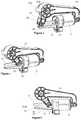
- FIG. 1is a three-dimensional view of a steering column with an electromechanical fixing device in a fixing position.
- FIG. 2is a partially exploded view of the fixing device.
- FIG. 3is a perspective detailed view of the fixing device in the fixing position.
- FIG. 4is a three-dimensional view of the fixing device in a release position.
- FIG. 5is a side view of the fixing device in the release position.
- FIG. 6is an electrical circuit with a potentiometer.
- FIG. 7is a second electrical circuit with a potentiometer.
- FIG. 8is a diagram with a measured voltage of a potentiometer plotted versus a movement travel.
- FIG. 9is a schematic view of a method for controlling the fixing device.
- FIG. 10is a three-dimensional view of a steering column having a stroke mechanism in a second embodiment.
- FIG. 11is a side view of a fixing device with light barrier.
- a steering column for a motor vehiclewhich steering column is adjustable in its longitudinal direction and/or in its vertical direction, comprising a casing tube which serves for rotatably mounting a steering spindle, a guide bracket which is connectable to the body of the motor vehicle and which comprises two side cheeks between which the casing tube is arranged, an electromechanical fixing device, in the release position of which the casing tube is adjustable relative to the guide bracket in the longitudinal direction and/or in the vertical direction of the steering column, and in the fixing position of which the set position of the casing tube is fixed relative to the guide bracket, wherein the fixing device comprises a clamping bolt, which extends through the side cheeks of the guide bracket and which, during the opening and closing of the fixing device, is rotatable about its axis by means of an electric motor, and a stroke-generating mechanism and a support bearing, wherein the side cheeks of the guide bracket and the casing tube are arranged between the stroke-generating mechanism and the support bearing.
- the electromechanical fixing deviceis particularly compact. Furthermore, a sensor is provided which is designed to detect a position of the lever. The state of the fixing device can be directly inferred from the position of the lever. It is thus possible to reliably retrieve the state of the fixing device.
- the sensorpreferably comprises a position sensor and/or at least one limit switch. Limit switches are to be understood to mean sensors which identify when a moving object has reached a particular position. By contrast, a position sensor measures a spacing between an object and a reference point.
- Both sensorsmake it possible to easily and reliably detect the position of the lever and thus the state of the fixing device.
- the casing tubeis thus configured such that it rotatably receives or bears the steering spindle formed as steering shaft.
- the position sensoris a potentiometer with a total resistance
- the levercomprises a slider which is movable with the lever along a movement travel and which, by means of a sliding contact, mechanically divides the electrically fixed total resistance into two partial resistances that correspond to said total resistance.
- the slideris arranged on an end of the lever remote from the clamping bolt and comprises a movement travel which extends at least from a fixing position of the clamping bolt into a release position of the clamping bolt.
- the at least one limit switchmay comprise a light barrier, wherein a position of the lever is detected by interruption of the light barrier.
- Such an absolute sensormay be provided in addition to the position sensor, for example in order to perform the detection of the state of the fixing device in the event of a fault.
- Usemay however also be made exclusively of limit switches.
- at least two limit switchesare provided in order to detect the attainment of both states, release position and fixing position.
- the stroke-generating mechanismcomprises two stroke-generating disks, wherein a first stroke-generating disk is connected rotationally conjointly to the clamping bolt and a second stroke-generating disk is guided on the clamping bolt in axially displaceable fashion in the housing, and wherein the housing is mounted in floating fashion on the second stroke-generating disk.
- the two stroke-generating disksmay for example comprise a cam contour. It is likewise conceivable and possible for rolling bodies or tilting pins to be arranged between the stroke-generating disks.
- the stroke-generating mechanismmay alternatively also comprise a nut which interacts with a thread on the clamping bolt and which provides a clamping stroke by means of the displacement of the nut in the direction of the axis of the clamping bolt.
- a rotor shaft of the electric motoris connected rotationally conjointly to a worm, wherein the worm meshes with a worm wheel which is connected rotationally conjointly to the first stroke-generating disk.
- the worm wheelforms the lever.
- the rotor shaft of the electric motorcomprises a threaded spindle which engages with a spindle nut, wherein the spindle nut is connected rotationally conjointly via the lever to the clamping bolt.
- All embodimentshave in common the fact that, preferably, the two stroke-generating disks as stroke-generating gearing interact with the support bearing in order to provide a clamping stroke for the fixing position of the fixing device.
- the diagnostic procedurepreferably comprises the following steps:
- FIG. 1illustrates a steering column 1 which comprises a steering spindle 2 which is mounted, so as to be rotatable about its axis of rotation 3 , in a steering spindle bearing unit 4 with a casing tube 5 .
- the casing tube 5is guided in a guide bracket 6 so as to be displaceable along the longitudinal axis of the steering spindle 2 .
- the casing tube 5is mounted in the guide bracket 6 so as to be pivotable about a pivot axis 7 .
- the guide bracket 6is held by a holding part 8 in the form of a console, wherein the guide bracket 6 together with the casing tube 5 can perform a displacement movement relative to the holding part 8 , with an absorption of energy, in the event of a frontal vehicle collision.
- the energy absorptionoccurs as a result of the plastic deformation of a deformation element, for example a bending-tearing tab 88 .
- the guide bracket 6may also be referred to as a carriage.
- the holding part 8may be fastened at fastening points 9 to the body (not illustrated) of a motor vehicle.
- the rotational movement introduced into the steering spindle 2 by a driver via a steering wheel (not illustrated)is introduced via a cardan joint 10 and further steering shaft parts into the steering gear (not illustrated).
- the steering column 1can be adjusted in terms of its height in a first adjustment direction, also referred to as vertical direction 11 , and in terms of its length in a second adjustment direction, also referred to as longitudinal direction 12 .
- a fixing device 13is provided, which comprises a clamping apparatus 14 .
- the casing tubemay be formed as an inner casing tube which is received displaceably in an outer casing tube, wherein the outer casing tube is supported pivotably by a guide bracket and the guide bracket is connectable to a body of a motor vehicle.
- the guide bracketit is possible for the guide bracket to be connected to the body of the motor vehicle both directly or with the interposition of a holding part.
- the clamping apparatus 14comprises a clamping bolt 15 , a stroke-generating mechanism 16 , a support bearing 155 and an electric motor 17 .
- the support bearingcomprises an axial bearing and a hexagonal nut with internal thread, which is couplable to a thread of the clamping bolt 15 .
- the axial bearingis preferably in the form of a rolling bearing, and is arranged between the side cheek 18 and the hexagonal nut.
- the clamping bolt 15extends through slots 199 in the side cheeks 18 , 19 of the guide bracket and through holes 55 in the side surfaces of the casing tube 5 .
- the stroke mechanism 16is arranged on that end of the clamping bolt 15 which is close to the electric motor, and the support bearing 155 is arranged on the other end of the clamping bolt 15 .
- the side cheeks 18 , 19 and the casing tube 5are arranged between the stroke-generating mechanism 16 and the support bearing 155 .
- the fixing deviceBy rotation of the clamping bolt 15 , the fixing device can be switched selectively into a release position, also referred to as opened position, or a fixing position, also referred to as closed position.
- a release positionalso referred to as opened position
- a fixing positionalso referred to as closed position.
- the steering spindle 2or the steering wheel fastened thereto (not illustrated in the figures), can be adjusted in terms of its position, in particular displaced in the longitudinal direction and in the height or tilt direction.
- the fixing position of the fixing device 13the casing tube 5 is fixed in its position relative to the guide bracket 6 .
- the electric motor 17comprises a rotor shaft 20 with a threaded spindle 21 , which is in operative engagement with a spindle nut 22 .
- the spindle nut 22is connected to a lever 23 , which is connected rotationally conjointly to a first cam disk 24 , which interacts with a second cam disk 25 as a stroke gearing for the purposes of providing a clamping stroke.
- the spindle nut 22is connected to the lever 23 so as to be pivotable about an axis oriented orthogonally with respect to the longitudinal axis of the threaded spindle 21 .
- the electric motor 17 and the lever 23are arranged in a housing.
- the second cam disk 25comprises two lugs 26 which project radially out of a substantially circular basic shape and which are situated diametrically opposite one another, and two projections 27 which protrude in the direction of the guide bracket 6 .
- the housing 222has a recess for the leadthrough of the clamping bolt 15 , which is shaped so as to form a guide for the second cam disk 25 exclusively in an axial direction. A rotation of the second cam disk 25 with the clamping bolt 15 is thus ruled out.
- the housing 222 of the electromechanical fixing device 13is mounted in floating fashion on the second cam disk 25 and can move axially on the clamping bolt 15 and the second cam disk 25 during the transfer between the fixing position and the release position.
- the electric motor 17is held, on a side remote from the threaded spindle, on the housing 222 by means of a joint 223 . Said joint 223 is necessary to compensate angular compensation that occurs during the actuation of the lever 23 .
- the spindle nut 22is moved on the threaded spindle along a longitudinal axis by means of the electric motor 17 .
- the lever 23is connected to the spindle nut 22 .
- a movement of the spindle nut 22pivots the lever 23 about a pivot axis which coincides with a longitudinal axis of the clamping bolt.
- the leveris connected to the clamping bolt such that a pivoting of the lever 23 effects a rotation of the clamping bolt 15 .
- a detection device 28is provided which detects the position of the lever 23 and thus the state of the fixing device.
- the detection device 28may comprise a potentiometer or a limit switch, for example a light barrier.
- a set of electronicscontrols safety-relevant states of the clamping.
- FIGS. 3 and 4illustrate the fixing position and the release position of the fixing device in detail.
- the first cam disk 24 connected rotationally conjointly theretois rotated relative to the second cam disk 25 .
- the spacing between the lever 23 and the casing tube 5changes.
- the spacingis increased by virtue of the two cam disks 24 , 25 being turned away from one another and thus the depth of the two components being increased, such that the second cam disk 25 is pushed out of the recess 300 of the housing 222 and is supported on the side cheek 19 of the guide bracket 6 and, here, pulls the support bearing 155 toward the opposite side cheek 18 of the guide bracket 6 .
- the fixing deviceis now braced such that the side cheeks 18 , 19 of the guide bracket 6 have been pulled together, whereby frictionally locking bracing of the side cheeks 18 , 19 with the side surfaces of the casing tube 5 is realized.
- the spacing between the fixing device 13has a greater value in the fixing position than in the release position, because the side cheeks 18 , 19 are pulled together.
- the position of the lever 23is measured by means of the detection device 28 .
- the first cam disk 24is rotated relative to the second cam disk 25 until the two components engage into one another and the depth thereof decreases.
- the second cam disk 25is displaced in the housing 222 axially in the direction of the lever 23 , and the support bearing 155 moves away from the side cheeks 18 , 19 .
- the bracing of the fixing device 13is thus released, and the casing tube 5 of the steering column 1 is released for adjustment.
- a potentiometer 28is provided as position sensor, which detects the position of the lever 23 along a lever travel relative to a reference position.
- the potentiometer 28comprises an ohmic resistance with a displaceable pickup, at which a variable partial resistance can be picked up.
- the total resistancerepresents the measurement range over which a position measurement is possible.
- a voltage UOis applied to the potentiometer.
- a voltage Ux proportional to the travel xcan then be measured.
- the position informationis accordingly, by means of the potentiometer, firstly converted mechanically into a proportional ohmic resistance and subsequently changed into a proportional electrical voltage signal.
- the position sensorcomprises a carrier with a resistance layer 29 applied to a surface 30 .
- Said carrieris arranged fixedly with its surface 30 parallel to the rotor shaft 21 of the electric motor 17 , and comprises two electrical terminals at an end 31 close to the electric motor, and at an end 32 remote from the electric motor, of the lever travel.
- a movable slider 33is fixedly connected to the lever 23 , which slider, by way of sliding contact, mechanically divides the electrically fixed total resistance of the carrier into two partial resistances which collectively correspond to said total resistance, and constitutes a pickup.
- a change in resistancecan be detected by virtue of a voltage measuring unit (voltmeter), as illustrated in FIG. 6 , being connected in parallel with respect to the potentiometer.
- the measured voltage Uxis a measure for the relative position x of the slider in relation to the ends 31 , 32 .
- FIG. 7illustrates a second possible electrical circuit, in which the voltage Ux prevailing between ground and the pickup is measured.
- the sensoris calibrated to be able to assign a particular position x to a particular voltage Ux.
- movement to the stops of the movement travel of the leveris performed, and the measured voltage values Ux are assigned to the travel x covered.
- This one-off initializationis preferably performed at the assembly plant, and the measured values are stored. Therefore, in general, no further initialization is required in the automobile. In the case of such an absolute length measurement system being used, the movement speed of the fixing device can be controlled in open-loop or closed-loop fashion.
- the state in which the fixing device is situatedis determined.
- the diagramshows the measured voltage Ux plotted versus the movement travel x.
- the travel xis the movement travel of that end of the lever 23 which is remote from the clamping bolt from the end 31 close to the electric motor to the end 32 remote from the electric motor.
- the leverIn the fixing position 342 , the lever is situated at the stop remote from the motor, in the vicinity of which stop the measured voltage Ux corresponds approximately to UO, the voltage of the total resistance.
- FIG. 9illustrates a flow diagram showing a method for operating the electrical fixing device.
- a first step 35the fixing device is connected to the on-board electrical system of the vehicle. Subsequently, the state of the fixing device is queried 36 . If the fixing device is situated in the release position 361 , then the motor is activated in order to move 37 the device into the fixing position. If the fixing device is situated in the fixing position, then actuation 38 of the fixing mechanism by the driver for the purposes of moving the steering column is awaited. If such an actuation is detected 39 , for example as a result of an actuating button being depressed, the electric motor moves the fixing device into the release position 40 . Subsequently, the state of the fixing device is checked 41 again.
- a diagnostic procedureis started 42 .
- the query yields that the fixing device is situated in the release positiona signal from the driver for the purposes of fixing the device again is awaited 43 .
- a certain timeis provided for this. If this time is overshot 44 , then the electric motor is activated 441 , 37 in order to fix the device in the absence of a signal from the driver. If the signal from the driver for fixing 45 arrives within the time period, the motor is thereupon likewise activated in order to move 37 the device into the fixing position. Thereafter, the state of the device is queried 46 again.
- the diagnostic procedure 42is started again, otherwise the sequence starts from the beginning and a signal from the driver for the purposes of opening the device is awaited 38 .
- the diagnostic procedurecomprises the following method steps:
- an additional absolute sensorfor example a limit sensor.
- the second fault signalis preferably processed by the vehicle such that a warning lamp or a display that is provided informs the driver of the state of the fixing device.
- the lever 23is formed by a worm wheel of segment-like form.
- a worm 47is connected rotationally conjointly to the rotor shaft 20 .
- the rotor shaft 20 and the worm 47are arranged perpendicular to the clamping bolt 15 .
- the worm 47meshes with the circular-sector-shaped worm wheel 23 , which is mounted so as to be pivotable about the axis of rotation of the clamping bolt 15 .
- the worm wheel 23is operatively connected to the first clamping disk.
- the position sensor 28measures the position of the lever 23 along the lever travel.
- FIG. 11illustrates a possible embodiment with a multiplicity of light barriers 48 .
- the lever 23moves from the fixing position into the release position and vice versa through the light barriers 48 , whereby the position of the lever 28 can be determined by detecting the interruption of the light barriers.
- the adjustable steering column 1comprises an electromechanical fixing device 13 , in the case of which the position of the lever relative to the housing is measured in order to determine the situation of the clamping lever. In this way, safety can be increased, because functional errors can be detected at an early point in time. It is preferable here if the housing of the fixing device is mounted in floating fashion on the second cam disk and can move in the axial direction of the clamping bolt. An additional fastening of the housing to the body is thus not necessary, and a compact design can be made possible. A desired modularity of the fixing device can be realized by means of different thread pitches and lever lengths. It is likewise conceivable and possible for the thread to be of single-start or multi-start design.
Landscapes
- Engineering & Computer Science (AREA)
- Chemical & Material Sciences (AREA)
- Combustion & Propulsion (AREA)
- Transportation (AREA)
- Mechanical Engineering (AREA)
- Steering Controls (AREA)
- Power Steering Mechanism (AREA)
Abstract
Description
- after actuation of the fixing mechanism by means of an actuating device in order to set a position of a steering column, moving the fixing device into the release position by means of the electric motor;
- checking the state of the fixing device by means of the sensor; if the check yields that the fixing device is not situated in the release position, starting a diagnostic procedure; if the check yields that the fixing device is situated in the release position, waiting for an actuation of the actuating device for the purposes of immobilizing the position of the steering column;
- if an actuation for the purposes of immobilizing the position of the steering column is not detected in a predetermined time, moving the fixing device into the fixing position by means of the electric motor;
- if an actuation for the purposes of immobilizing the position of the steering column is detected in a predetermined time, moving the fixing device into the fixing position by means of the electric motor;
- checking the state of the fixing device by means of the sensor; if the check yields that the fixing device is not situated in the fixing position, starting a diagnostic procedure.
- electrically energizing the electric motor in the direction of the release position for a predefined period, and monitoring the sensor with regard to changes in position;
- if the release position is not reached, transmitting a fault signal to the motor vehicle and activating the motor until the fixing position is reached; in the process, monitoring the sensor with regard to changes in position;
- if the fixing position is not reached, transmitting a second fault signal to the motor vehicle.
- electrically energizing the motor in the direction of the release position for a predefined period (in particular 20 s), and monitoring the position sensor with regard to changes in position;
- if the release position is not reached, transmitting a fault signal to the vehicle and activating the motor until the fixing position is reached; in the process, monitoring the position sensor with regard to changes in position;
- if the fixing position is not reached, transmitting a second fault signal (critical error) to the vehicle.
Claims (13)
Applications Claiming Priority (3)
| Application Number | Priority Date | Filing Date | Title |
|---|---|---|---|
| DE102016008561.4ADE102016008561A1 (en) | 2016-07-14 | 2016-07-14 | Steering column with electro-mechanical fixing device |
| DE102016008561.4 | 2016-07-14 | ||
| PCT/EP2017/066878WO2018011044A1 (en) | 2016-07-14 | 2017-07-06 | Steering column having an electro-mechanical fixing device |
Publications (2)
| Publication Number | Publication Date |
|---|---|
| US20190291773A1 US20190291773A1 (en) | 2019-09-26 |
| US10933902B2true US10933902B2 (en) | 2021-03-02 |
Family
ID=59315608
Family Applications (1)
| Application Number | Title | Priority Date | Filing Date |
|---|---|---|---|
| US16/317,174Expired - Fee RelatedUS10933902B2 (en) | 2016-07-14 | 2017-07-06 | Steering column having an electro-mechanical fixing device |
Country Status (6)
| Country | Link |
|---|---|
| US (1) | US10933902B2 (en) |
| EP (1) | EP3484759B1 (en) |
| CN (1) | CN109476334B (en) |
| DE (1) | DE102016008561A1 (en) |
| ES (1) | ES2899942T3 (en) |
| WO (1) | WO2018011044A1 (en) |
Cited By (3)
| Publication number | Priority date | Publication date | Assignee | Title |
|---|---|---|---|---|
| US20220410962A1 (en)* | 2019-11-22 | 2022-12-29 | Robert Bosch Automotive Steering Vendome | Steering Column Sleeve comprising a System for Adjusting a Relative Position between Two Tubes |
| US20240336294A1 (en)* | 2023-04-04 | 2024-10-10 | Hl Mando Corporation | Vehicle steering column |
| US12263880B2 (en)* | 2023-03-31 | 2025-04-01 | Hl Mando Corporation | Steering device of vehicle |
Families Citing this family (6)
| Publication number | Priority date | Publication date | Assignee | Title |
|---|---|---|---|---|
| DE102017114517A1 (en)* | 2017-06-29 | 2019-01-03 | Thyssenkrupp Ag | Adjustable steering column with at least one MRF actuator |
| US10793179B2 (en)* | 2018-08-06 | 2020-10-06 | Steering Solutions Ip Holding Corporation | Adjustable steering column assembly |
| US11465681B2 (en)* | 2019-04-12 | 2022-10-11 | Steering Solutions Ip Holding Corporation | Position identification assembly for steering column |
| DE102019209135A1 (en)* | 2019-06-25 | 2020-12-31 | Brose Fahrzeugteile SE & Co. Kommanditgesellschaft, Coburg | Electrically adjustable steering device of a land-based motor vehicle |
| CN110497966B (en)* | 2019-09-04 | 2021-08-27 | 李龙德 | Automobile body longitudinal beam structure |
| CN119036368B (en)* | 2024-10-30 | 2025-02-18 | 中建八局第一建设有限公司 | Auxiliary installation device capable of positioning and adjusting for installing electromechanical equipment |
Citations (43)
| Publication number | Priority date | Publication date | Assignee | Title |
|---|---|---|---|---|
| US4503504A (en)* | 1981-08-21 | 1985-03-05 | Aisin Seiki Kabushiki Kaisha | Attitude controlling device for a steering wheel |
| US4612822A (en)* | 1983-06-13 | 1986-09-23 | Aisin Seiki Kabushiki Kaisha | Tilt steering equipment |
| US4661752A (en)* | 1984-09-10 | 1987-04-28 | Aisin Seiki Kabushiki Kaisha | Attitude controlling system for a steering wheel |
| US4752085A (en)* | 1985-10-14 | 1988-06-21 | Fuji Kiko Company, Limited | Powered tilt steering arrangement |
| US4978137A (en)* | 1988-10-06 | 1990-12-18 | Nissan Motor Co., Ltd. | System and method for controlling posture of steering wheel for vehicle |
| US5240284A (en)* | 1989-06-07 | 1993-08-31 | Fuji Kiko Company, Limited | Steering column assembly with horizontal position adjustment mechanism |
| US5275066A (en)* | 1991-11-07 | 1994-01-04 | The Torrington Company | Motored adjustable steering column |
| EP0600700A1 (en) | 1992-12-02 | 1994-06-08 | The Torrington Company Limited | Steering column clamping mechanism |
| US5477744A (en)* | 1992-09-28 | 1995-12-26 | Equipments Et Composants Pour L'industrie Automobile | Position adustable steering column assembly for a motor vehicle |
| US5806890A (en)* | 1995-12-26 | 1998-09-15 | Aisin Seiki Kabushiki Kaisha | Steering wheel position adjusting apparatus for a vehicular steering system |
| US6237438B1 (en)* | 1998-07-13 | 2001-05-29 | Lemfördes Nacam SA | Electrically controlled clamping system |
| US6543807B2 (en)* | 2000-07-07 | 2003-04-08 | Kabushiki Kaisha Yamada Seisakusho | Steering position adjustment device |
| US20040023746A1 (en)* | 2002-07-31 | 2004-02-05 | Fuji Kiko Co., Ltd. | Tilt adjustable steering column assembly |
| US20050034493A1 (en)* | 2002-07-23 | 2005-02-17 | Huf Hulsbeck & Furst Gmbh & Co. Kg | Locking system for motor vehicles |
| US20050081675A1 (en)* | 2003-05-30 | 2005-04-21 | Aisin Seiki Kabushiki Kaisha | Steering apparatus |
| US20050097978A1 (en)* | 2003-11-12 | 2005-05-12 | Ben Rhouma Abdel K. | Adjustable steering column including electrically-operable locking means |
| US20060005658A1 (en)* | 2004-07-02 | 2006-01-12 | Armstrong Ray G | Electrical tilt and telescope locking mechanism |
| US20060266151A1 (en)* | 2005-05-25 | 2006-11-30 | Admiral Tool And Manufacturing Company, Inc. | Power adjust tilt-telescope steering column |
| US20070068311A1 (en)* | 2005-09-08 | 2007-03-29 | Nsk Ltd. | Steering apparatus |
| US20080121489A1 (en)* | 2005-03-07 | 2008-05-29 | John Phillip Chevalier | Centrifugal Clutch and Actuator |
| US20080128197A1 (en)* | 2006-11-30 | 2008-06-05 | Nsk Ltd. | Electric steering apparatus |
| US20090007612A1 (en)* | 2004-11-05 | 2009-01-08 | Valeo Sicherheitssysteme Gmbh | Safe Gear Box for Electrical Steering Column Lock |
| US7631898B2 (en)* | 2006-01-25 | 2009-12-15 | Chrysler Group Llc | Power release and locking adjustable steering column apparatus and method |
| US7730804B2 (en)* | 2007-03-21 | 2010-06-08 | Gm Global Technology Operations, Inc. | Central lock device of an adjustable steering column assembly |
| FR2947233A1 (en) | 2009-06-30 | 2010-12-31 | Zf Systemes De Direction Nacam Sas | ELECTRIC LOCKING SYSTEM OF A STEERING COLUMN AND STEERING COLUMN COMPRISING SUCH A LATCHING SYSTEM |
| US20110167948A1 (en)* | 2010-01-14 | 2011-07-14 | Tobias Andrearczyk | Steering column module including a steering column with a longitudinal and/or inclination adjustment |
| US8056437B2 (en)* | 2005-04-19 | 2011-11-15 | Nexteer (Beijing) Technology Co., Ltd. | Electric steering column lock with single direction actuator travel |
| US8146945B2 (en)* | 2002-11-07 | 2012-04-03 | Daimler Ag | Motor vehicle steering column |
| US8701834B2 (en)* | 2010-08-20 | 2014-04-22 | Nook Industries, Inc. | Mechanical actuator |
| US8763491B2 (en)* | 2011-11-03 | 2014-07-01 | Steering Solutions Ip Holding Corporation | Adjustment assembly having a variable gear ratio |
| US20140260761A1 (en)* | 2013-03-15 | 2014-09-18 | Ford Global Technologies, Llc | Method and system for stowing steering column in a vehicle |
| US8844400B2 (en)* | 2011-09-26 | 2014-09-30 | Aisin Seiki Kabushiki Kaisha | Steering apparatus for vehicle |
| US8882147B2 (en)* | 2009-11-27 | 2014-11-11 | Thyssenkrupp Presta Aktiengesellschaft | Steering column for a motor vehicle |
| US8909433B2 (en)* | 2011-11-21 | 2014-12-09 | Hyundai Motor Company | System of controlling steering apparatus of vehicle and method for supplying current thereof |
| US8985628B2 (en)* | 2011-08-16 | 2015-03-24 | GM Global Technology Operations LLC | Adjusting device |
| US20150344063A1 (en)* | 2014-05-29 | 2015-12-03 | Aisin Seiki Kabushiki Kaisha | Vehicle steering apparatus |
| US20150375769A1 (en)* | 2013-02-08 | 2015-12-31 | Robert Bosch Automotive Steering Llc | Adjustable Steering Column Controlled By A Human Machine Interface |
| US9321476B2 (en)* | 2012-02-10 | 2016-04-26 | Aisin Seiki Kabushiki Kaisha | Steering apparatus for a vehicle |
| US20160144883A1 (en) | 2014-11-25 | 2016-05-26 | Steering Solutions Ip Holding Corporation | Systems for detecting locked condition of steering column |
| US9586610B2 (en)* | 2015-08-06 | 2017-03-07 | GM Global Technology Operations LLC | Steering column rake adjustment lock/unlock device |
| US9919724B2 (en)* | 2015-05-29 | 2018-03-20 | Steering Solutions Ip Holding Corporation | Retractable steering column with manual retrieval |
| US10449992B2 (en)* | 2015-06-19 | 2019-10-22 | Thyssenkrupp Presta Ag | Steering column having an electro-mechanical fixing device |
| US10648218B1 (en)* | 2019-05-31 | 2020-05-12 | Haier Us Appliance Solutions, Inc. | Refrigerator with push-to-open door opener |
- 2016
- 2016-07-14DEDE102016008561.4Apatent/DE102016008561A1/ennot_activeWithdrawn
- 2017
- 2017-07-06WOPCT/EP2017/066878patent/WO2018011044A1/ennot_activeCeased
- 2017-07-06CNCN201780043030.2Apatent/CN109476334B/ennot_activeExpired - Fee Related
- 2017-07-06EPEP17737772.8Apatent/EP3484759B1/enactiveActive
- 2017-07-06USUS16/317,174patent/US10933902B2/ennot_activeExpired - Fee Related
- 2017-07-06ESES17737772Tpatent/ES2899942T3/enactiveActive
Patent Citations (49)
| Publication number | Priority date | Publication date | Assignee | Title |
|---|---|---|---|---|
| US4503504A (en)* | 1981-08-21 | 1985-03-05 | Aisin Seiki Kabushiki Kaisha | Attitude controlling device for a steering wheel |
| US4612822A (en)* | 1983-06-13 | 1986-09-23 | Aisin Seiki Kabushiki Kaisha | Tilt steering equipment |
| US4661752A (en)* | 1984-09-10 | 1987-04-28 | Aisin Seiki Kabushiki Kaisha | Attitude controlling system for a steering wheel |
| US4752085A (en)* | 1985-10-14 | 1988-06-21 | Fuji Kiko Company, Limited | Powered tilt steering arrangement |
| US4978137A (en)* | 1988-10-06 | 1990-12-18 | Nissan Motor Co., Ltd. | System and method for controlling posture of steering wheel for vehicle |
| US5240284A (en)* | 1989-06-07 | 1993-08-31 | Fuji Kiko Company, Limited | Steering column assembly with horizontal position adjustment mechanism |
| US5275066A (en)* | 1991-11-07 | 1994-01-04 | The Torrington Company | Motored adjustable steering column |
| US5477744A (en)* | 1992-09-28 | 1995-12-26 | Equipments Et Composants Pour L'industrie Automobile | Position adustable steering column assembly for a motor vehicle |
| EP0600700A1 (en) | 1992-12-02 | 1994-06-08 | The Torrington Company Limited | Steering column clamping mechanism |
| US5806890A (en)* | 1995-12-26 | 1998-09-15 | Aisin Seiki Kabushiki Kaisha | Steering wheel position adjusting apparatus for a vehicular steering system |
| US6237438B1 (en)* | 1998-07-13 | 2001-05-29 | Lemfördes Nacam SA | Electrically controlled clamping system |
| DE69919639T2 (en) | 1998-07-13 | 2005-09-08 | Lemförder Nacam S.A. | An electrically operated tensioning device for a system for adjusting the position of one part relative to another part |
| US6543807B2 (en)* | 2000-07-07 | 2003-04-08 | Kabushiki Kaisha Yamada Seisakusho | Steering position adjustment device |
| US20050034493A1 (en)* | 2002-07-23 | 2005-02-17 | Huf Hulsbeck & Furst Gmbh & Co. Kg | Locking system for motor vehicles |
| US20040023746A1 (en)* | 2002-07-31 | 2004-02-05 | Fuji Kiko Co., Ltd. | Tilt adjustable steering column assembly |
| US8146945B2 (en)* | 2002-11-07 | 2012-04-03 | Daimler Ag | Motor vehicle steering column |
| US20050081675A1 (en)* | 2003-05-30 | 2005-04-21 | Aisin Seiki Kabushiki Kaisha | Steering apparatus |
| US20050097978A1 (en)* | 2003-11-12 | 2005-05-12 | Ben Rhouma Abdel K. | Adjustable steering column including electrically-operable locking means |
| US7367246B2 (en)* | 2003-11-12 | 2008-05-06 | Nacam France S.A.S. | Adjustable steering column including electrically-operable locking means |
| US20060005658A1 (en)* | 2004-07-02 | 2006-01-12 | Armstrong Ray G | Electrical tilt and telescope locking mechanism |
| US7178422B2 (en)* | 2004-07-02 | 2007-02-20 | Delphi Technologies, Inc. | Electrical tilt and telescope locking mechanism |
| US20090007612A1 (en)* | 2004-11-05 | 2009-01-08 | Valeo Sicherheitssysteme Gmbh | Safe Gear Box for Electrical Steering Column Lock |
| US20080121489A1 (en)* | 2005-03-07 | 2008-05-29 | John Phillip Chevalier | Centrifugal Clutch and Actuator |
| US8056437B2 (en)* | 2005-04-19 | 2011-11-15 | Nexteer (Beijing) Technology Co., Ltd. | Electric steering column lock with single direction actuator travel |
| US20060266151A1 (en)* | 2005-05-25 | 2006-11-30 | Admiral Tool And Manufacturing Company, Inc. | Power adjust tilt-telescope steering column |
| US20070068311A1 (en)* | 2005-09-08 | 2007-03-29 | Nsk Ltd. | Steering apparatus |
| US7631898B2 (en)* | 2006-01-25 | 2009-12-15 | Chrysler Group Llc | Power release and locking adjustable steering column apparatus and method |
| US20080128197A1 (en)* | 2006-11-30 | 2008-06-05 | Nsk Ltd. | Electric steering apparatus |
| US7730804B2 (en)* | 2007-03-21 | 2010-06-08 | Gm Global Technology Operations, Inc. | Central lock device of an adjustable steering column assembly |
| FR2947233A1 (en) | 2009-06-30 | 2010-12-31 | Zf Systemes De Direction Nacam Sas | ELECTRIC LOCKING SYSTEM OF A STEERING COLUMN AND STEERING COLUMN COMPRISING SUCH A LATCHING SYSTEM |
| US8910540B2 (en)* | 2009-06-30 | 2014-12-16 | Zf Systemes De Direction Nacam S.A.S. | System for electrically locking a steering column, and steering column including such a locking system |
| US8882147B2 (en)* | 2009-11-27 | 2014-11-11 | Thyssenkrupp Presta Aktiengesellschaft | Steering column for a motor vehicle |
| US20110167948A1 (en)* | 2010-01-14 | 2011-07-14 | Tobias Andrearczyk | Steering column module including a steering column with a longitudinal and/or inclination adjustment |
| DE102010039896A1 (en) | 2010-01-14 | 2011-07-21 | C. Rob. Hammerstein GmbH & Co. KG, 42699 | Steering column module with a steering column with longitudinal and / or tilt adjustment of the steering column |
| US8701834B2 (en)* | 2010-08-20 | 2014-04-22 | Nook Industries, Inc. | Mechanical actuator |
| US8985628B2 (en)* | 2011-08-16 | 2015-03-24 | GM Global Technology Operations LLC | Adjusting device |
| US8844400B2 (en)* | 2011-09-26 | 2014-09-30 | Aisin Seiki Kabushiki Kaisha | Steering apparatus for vehicle |
| US8763491B2 (en)* | 2011-11-03 | 2014-07-01 | Steering Solutions Ip Holding Corporation | Adjustment assembly having a variable gear ratio |
| US8909433B2 (en)* | 2011-11-21 | 2014-12-09 | Hyundai Motor Company | System of controlling steering apparatus of vehicle and method for supplying current thereof |
| US9321476B2 (en)* | 2012-02-10 | 2016-04-26 | Aisin Seiki Kabushiki Kaisha | Steering apparatus for a vehicle |
| US20150375769A1 (en)* | 2013-02-08 | 2015-12-31 | Robert Bosch Automotive Steering Llc | Adjustable Steering Column Controlled By A Human Machine Interface |
| US20140260761A1 (en)* | 2013-03-15 | 2014-09-18 | Ford Global Technologies, Llc | Method and system for stowing steering column in a vehicle |
| US20150344063A1 (en)* | 2014-05-29 | 2015-12-03 | Aisin Seiki Kabushiki Kaisha | Vehicle steering apparatus |
| US20160144883A1 (en) | 2014-11-25 | 2016-05-26 | Steering Solutions Ip Holding Corporation | Systems for detecting locked condition of steering column |
| US9428211B2 (en)* | 2014-11-25 | 2016-08-30 | Steering Solutions Ip Holding Corporation | Systems for detecting locked condition of steering column |
| US9919724B2 (en)* | 2015-05-29 | 2018-03-20 | Steering Solutions Ip Holding Corporation | Retractable steering column with manual retrieval |
| US10449992B2 (en)* | 2015-06-19 | 2019-10-22 | Thyssenkrupp Presta Ag | Steering column having an electro-mechanical fixing device |
| US9586610B2 (en)* | 2015-08-06 | 2017-03-07 | GM Global Technology Operations LLC | Steering column rake adjustment lock/unlock device |
| US10648218B1 (en)* | 2019-05-31 | 2020-05-12 | Haier Us Appliance Solutions, Inc. | Refrigerator with push-to-open door opener |
Non-Patent Citations (1)
| Title |
|---|
| English Translation of International Search Report issued in PCT/EP2017/066878, dated Oct. 25, 2017. |
Cited By (4)
| Publication number | Priority date | Publication date | Assignee | Title |
|---|---|---|---|---|
| US20220410962A1 (en)* | 2019-11-22 | 2022-12-29 | Robert Bosch Automotive Steering Vendome | Steering Column Sleeve comprising a System for Adjusting a Relative Position between Two Tubes |
| US11919564B2 (en)* | 2019-11-22 | 2024-03-05 | Robert Bosch Automotive Steering Vendome | Steering column sleeve comprising a system for adjusting a relative position between two tubes |
| US12263880B2 (en)* | 2023-03-31 | 2025-04-01 | Hl Mando Corporation | Steering device of vehicle |
| US20240336294A1 (en)* | 2023-04-04 | 2024-10-10 | Hl Mando Corporation | Vehicle steering column |
Also Published As
| Publication number | Publication date |
|---|---|
| CN109476334B (en) | 2021-12-21 |
| EP3484759B1 (en) | 2021-09-01 |
| EP3484759A1 (en) | 2019-05-22 |
| ES2899942T3 (en) | 2022-03-15 |
| WO2018011044A1 (en) | 2018-01-18 |
| DE102016008561A1 (en) | 2018-01-18 |
| CN109476334A (en) | 2019-03-15 |
| US20190291773A1 (en) | 2019-09-26 |
Similar Documents
| Publication | Publication Date | Title |
|---|---|---|
| US10933902B2 (en) | Steering column having an electro-mechanical fixing device | |
| US12139188B2 (en) | Position detection for a steering column of a motor vehicle | |
| US7533594B2 (en) | Position control apparatus for steering column | |
| US7159904B2 (en) | Steering column for a motor vehicle | |
| US9428211B2 (en) | Systems for detecting locked condition of steering column | |
| US6851655B2 (en) | Seat rail system with position sensor | |
| JP4606538B2 (en) | Device for electrically locking a steering shaft in a steering device | |
| US20160009311A1 (en) | Friction clutch for steering column | |
| JPH0453746B2 (en) | ||
| US20020078786A1 (en) | Control system for adjustable pedal assembly | |
| KR20160075544A (en) | Vehicle door control system | |
| US11667322B2 (en) | Steering column assembly | |
| US12049249B2 (en) | Steering column for a motor vehicle | |
| SE533685C2 (en) | Adjustable control device with mechanical memory | |
| EP1094380B1 (en) | Angle detecting device | |
| CN117043041A (en) | Method for adjusting a positioning unit of a steering column and electrically adjustable steering column | |
| US7743681B2 (en) | Steering column assembly having an actuation mechanism for telescoping and tilting movement | |
| WO2004087483A2 (en) | Improved steering column assembly | |
| US20190016300A1 (en) | Steering column with an electrical steering lock | |
| US8960046B2 (en) | Locking device for a vehicle steering system | |
| US20250276615A1 (en) | Device for adjusting a seat, and installation assembly for such a device | |
| US6647814B2 (en) | Selective drive mechanism | |
| CN116601071A (en) | Steering column with adjustability that can be monitored and method for operating such a steering column | |
| JPH0351616B2 (en) | ||
| JPH0794223B2 (en) | On-board posture setting device |
Legal Events
| Date | Code | Title | Description |
|---|---|---|---|
| FEPP | Fee payment procedure | Free format text:ENTITY STATUS SET TO UNDISCOUNTED (ORIGINAL EVENT CODE: BIG.); ENTITY STATUS OF PATENT OWNER: LARGE ENTITY | |
| AS | Assignment | Owner name:THYSSENKRUPP AG, GERMANY Free format text:ASSIGNMENT OF ASSIGNORS INTEREST;ASSIGNORS:SPECHT, JEAN-PIERRE;MUNDING, CHRISTOPH;SIGNING DATES FROM 20190122 TO 20190123;REEL/FRAME:048152/0238 Owner name:THYSSENKRUPP PRESTA AG, LIECHTENSTEIN Free format text:ASSIGNMENT OF ASSIGNORS INTEREST;ASSIGNORS:SPECHT, JEAN-PIERRE;MUNDING, CHRISTOPH;SIGNING DATES FROM 20190122 TO 20190123;REEL/FRAME:048152/0238 | |
| STPP | Information on status: patent application and granting procedure in general | Free format text:NON FINAL ACTION MAILED | |
| STPP | Information on status: patent application and granting procedure in general | Free format text:NON FINAL ACTION MAILED | |
| STPP | Information on status: patent application and granting procedure in general | Free format text:FINAL REJECTION MAILED | |
| STCF | Information on status: patent grant | Free format text:PATENTED CASE | |
| FEPP | Fee payment procedure | Free format text:MAINTENANCE FEE REMINDER MAILED (ORIGINAL EVENT CODE: REM.); ENTITY STATUS OF PATENT OWNER: LARGE ENTITY | |
| LAPS | Lapse for failure to pay maintenance fees | Free format text:PATENT EXPIRED FOR FAILURE TO PAY MAINTENANCE FEES (ORIGINAL EVENT CODE: EXP.); ENTITY STATUS OF PATENT OWNER: LARGE ENTITY | |
| STCH | Information on status: patent discontinuation | Free format text:PATENT EXPIRED DUE TO NONPAYMENT OF MAINTENANCE FEES UNDER 37 CFR 1.362 | |
| FP | Lapsed due to failure to pay maintenance fee | Effective date:20250302 |