US10933238B2 - Power control circuit for sterilized devices, and associated systems and methods - Google Patents
Power control circuit for sterilized devices, and associated systems and methodsDownload PDFInfo
- Publication number
- US10933238B2 US10933238B2US16/264,315US201916264315AUS10933238B2US 10933238 B2US10933238 B2US 10933238B2US 201916264315 AUS201916264315 AUS 201916264315AUS 10933238 B2US10933238 B2US 10933238B2
- Authority
- US
- United States
- Prior art keywords
- circuitry
- output
- control circuit
- switch
- power control
- Prior art date
- Legal status (The legal status is an assumption and is not a legal conclusion. Google has not performed a legal analysis and makes no representation as to the accuracy of the status listed.)
- Active
Links
Images


Classifications
- A—HUMAN NECESSITIES
- A61—MEDICAL OR VETERINARY SCIENCE; HYGIENE
- A61N—ELECTROTHERAPY; MAGNETOTHERAPY; RADIATION THERAPY; ULTRASOUND THERAPY
- A61N1/00—Electrotherapy; Circuits therefor
- A61N1/18—Applying electric currents by contact electrodes
- A61N1/32—Applying electric currents by contact electrodes alternating or intermittent currents
- A61N1/36—Applying electric currents by contact electrodes alternating or intermittent currents for stimulation
- A61N1/36014—External stimulators, e.g. with patch electrodes
- A61N1/36017—External stimulators, e.g. with patch electrodes with leads or electrodes penetrating the skin
- A—HUMAN NECESSITIES
- A61—MEDICAL OR VETERINARY SCIENCE; HYGIENE
- A61N—ELECTROTHERAPY; MAGNETOTHERAPY; RADIATION THERAPY; ULTRASOUND THERAPY
- A61N1/00—Electrotherapy; Circuits therefor
- A61N1/18—Applying electric currents by contact electrodes
- A61N1/32—Applying electric currents by contact electrodes alternating or intermittent currents
- A61N1/36—Applying electric currents by contact electrodes alternating or intermittent currents for stimulation
- A61N1/36014—External stimulators, e.g. with patch electrodes
- A61N1/3603—Control systems
- A61N1/36034—Control systems specified by the stimulation parameters
- A—HUMAN NECESSITIES
- A61—MEDICAL OR VETERINARY SCIENCE; HYGIENE
- A61N—ELECTROTHERAPY; MAGNETOTHERAPY; RADIATION THERAPY; ULTRASOUND THERAPY
- A61N1/00—Electrotherapy; Circuits therefor
- A61N1/18—Applying electric currents by contact electrodes
- A61N1/32—Applying electric currents by contact electrodes alternating or intermittent currents
- A61N1/36—Applying electric currents by contact electrodes alternating or intermittent currents for stimulation
- A61N1/36014—External stimulators, e.g. with patch electrodes
- A61N1/3603—Control systems
- A—HUMAN NECESSITIES
- A61—MEDICAL OR VETERINARY SCIENCE; HYGIENE
- A61N—ELECTROTHERAPY; MAGNETOTHERAPY; RADIATION THERAPY; ULTRASOUND THERAPY
- A61N1/00—Electrotherapy; Circuits therefor
- A61N1/18—Applying electric currents by contact electrodes
- A61N1/32—Applying electric currents by contact electrodes alternating or intermittent currents
- A61N1/36—Applying electric currents by contact electrodes alternating or intermittent currents for stimulation
- A61N1/372—Arrangements in connection with the implantation of stimulators
- A61N1/37211—Means for communicating with stimulators
- A61N1/37235—Aspects of the external programmer
- A61N1/37241—Aspects of the external programmer providing test stimulations
- G—PHYSICS
- G05—CONTROLLING; REGULATING
- G05F—SYSTEMS FOR REGULATING ELECTRIC OR MAGNETIC VARIABLES
- G05F1/00—Automatic systems in which deviations of an electric quantity from one or more predetermined values are detected at the output of the system and fed back to a device within the system to restore the detected quantity to its predetermined value or values, i.e. retroactive systems
- G05F1/10—Regulating voltage or current
- G05F1/46—Regulating voltage or current wherein the variable actually regulated by the final control device is DC
- G05F1/56—Regulating voltage or current wherein the variable actually regulated by the final control device is DC using semiconductor devices in series with the load as final control devices
- A—HUMAN NECESSITIES
- A61—MEDICAL OR VETERINARY SCIENCE; HYGIENE
- A61N—ELECTROTHERAPY; MAGNETOTHERAPY; RADIATION THERAPY; ULTRASOUND THERAPY
- A61N1/00—Electrotherapy; Circuits therefor
- A61N1/18—Applying electric currents by contact electrodes
- A61N1/32—Applying electric currents by contact electrodes alternating or intermittent currents
- A61N1/36—Applying electric currents by contact electrodes alternating or intermittent currents for stimulation
- A61N1/372—Arrangements in connection with the implantation of stimulators
- A61N2001/37294—Means for testing medical devices within the package prior to implantation
Definitions
- the presently disclosed technologyrelates generally to electronic medical devices that are to be sterilized in flammable environments prior to use and, in particular, to sterilizable trial stimulators for use with implantable neurological stimulation systems.
- Implantable neurological stimulation systemsgenerally have an implantable signal generator and one or more leads that deliver electrical pulses to neurological and/or muscle tissue. Often such devices have one or more electrodes that are inserted into the body near the target tissue to deliver the electrical pulses for therapeutic effect.
- the signal generatoris programmed to supply electrical pulses to the electrodes, which in turn modify the function of the patient's nervous system, such as by altering the patient's responsiveness to sensory stimuli and/or altering the patient's motor-circuit output.
- the signal generatorapplies electrical pulses to the spinal cord via the electrodes that mask or otherwise alter the patient's sensation of pain.
- an external trial stimulatoris attached to the implanted electrodes and can be programmed to deliver electrical pulses with varying signal levels, frequencies, time durations etc. If the patient responds well after wearing the trial stimulator, the patient receives a more permanent implantable stimulator.
- the implantable stimulatorcan be programmed with the therapy regimen that was determined to be the most beneficial during the trial period. If necessary, the signal generator can be further programmed while implanted to fine tune the most beneficial therapy regimen.
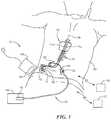
- FIG. 1is a partially schematic illustration of an implantable spinal cord modulation system positioned at a patient's spine to deliver therapeutic signals in accordance with some embodiments of the present technology.
- FIG. 2illustrates a trial stimulator that is placed in a sterile package and that wirelessly communicates with a programming unit in accordance with some embodiments of the disclosed technology.
- FIG. 3is a block diagram of a power control circuit for selectively reducing stored energy in a trial stimulator to be sterilized in accordance with some embodiments of the disclosed technology.
- FIG. 4is a schematic diagram of a power control circuit for selectively reducing stored energy in a trial stimulator to be sterilized in accordance with some embodiments of the disclosed technology.
- the present technologyis directed generally to power control circuits for selectively powering circuit components and, in some embodiments for selectively powering circuit components in sterilizable devices, and associated systems and methods.
- the presently disclosed technologiesare directed to systems and devices for discharging energy storage elements in a medical device that is to be placed in a flammable sterilizing gas after manufacture and prior to use.
- a bi-stable switchcan control one or more transistors to drain energy from an energy storage device to a level below an ignition level of a sterilizing gas.
- the bistable switchcan be triggered to change states via a remotely actuatable switch from outside a sealed packaging in which the circuit is placed so as not to break the sealed package in the process of re-activating the medical device.
- references to “some embodiments,” “one embodiment,” or the like,mean that the particular feature, function, structure or characteristic being described is included in at least one embodiment of the disclosed technology. Occurrences of such phrases in this specification do not necessarily all refer to the same embodiment. On the other hand, the embodiments referred to are not necessarily mutually exclusive. Elements described in the context of representative devices, systems and methods may be applied to other representative devices, systems and methods in a variety of suitable manners.
- the terms “modulate,” “modulation,” “stimulate,” and “stimulation”refer generally to signals that have an inhibitory, excitatory, and/or other effect on a target neural population. Accordingly, a spinal cord “stimulator” can have an inhibitory effect on certain neural populations.
- FIG. 1schematically illustrates a representative patient therapy system 100 for treating a patient's neurological disorders, arranged relative to the general anatomy of the patient's spinal column 191 .
- the system 100can include a signal generator 101 (e.g., an implanted or implantable pulse generator or IPG), which may be implanted subcutaneously within a patient 190 and coupled to one or more signal delivery elements or devices 110 .
- the signal delivery elements or devices 110may be implanted within the patient 190 , at or off the patient's spinal cord midline 189 .
- the signal delivery elements 110carry features for delivering therapy to the patient 190 after implantation.
- the signal generator 101can be connected directly to the signal delivery devices 110 , or it can be coupled to the signal delivery devices 110 via a signal link, e.g., a lead extension 102 .
- the signal delivery devices 110can include one or more elongated lead(s) or lead body or bodies 111 (identified individually as a first lead 111 a and a second lead 111 b ).
- the terms signal delivery device, signal delivery element, lead, and/or lead bodyinclude any of a number of suitable substrates and/or supporting members that carry electrodes/devices for providing therapy signals to the patient 190 .
- the lead or leads 111can include one or more electrodes or electrical contacts that direct electrical signals into the patient's tissue, e.g., to provide for therapeutic relief.
- the signal delivery elements 110can include structures other than a lead body (e.g., a paddle) that also direct electrical signals and/or other types of signals to the patient 190 , e.g., as disclosed in U.S. Patent Application Publication No. 2018/0256892, which is herein incorporated by reference in its entirety.
- paddlesmay be more suitable for patients with spinal cord injuries that result in scarring or other tissue damage that impedes signal delivery from cylindrical leads.
- one signal delivery devicemay be implanted on one side of the spinal cord midline 189
- a second signal delivery devicemay be implanted on the other side of the spinal cord midline 189
- the first and second leads 111 a , 111 b shown in FIG. 1may be positioned just off the spinal cord midline 189 (e.g., about 1 mm offset) in opposing lateral directions so that the two leads 111 a , 111 b are spaced apart from each other by about 2 mm.
- the leads 111may be implanted at a vertebral level ranging from, for example, about T4 to about T12.
- one or more signal delivery devicescan be implanted at other vertebral levels, e.g., as disclosed in U.S. Pat. No. 9,327,121, which is herein incorporated by reference in its entirety.
- the signal generator 101can provide signals (e.g., electrical signals) to the signal delivery elements 110 that excite and/or suppress target nerves.
- the signal generator 101can include a machine-readable (e.g., computer-readable) or controller-readable medium (e.g. a memory circuit) containing instructions that are executable by a processor for generating suitable therapy signals.
- the signal generator 101 and/or other elements of the system 100can include one or more processor(s) 107 , memory unit(s) 108 , and/or input/output device(s) 112 .
- instructions for performing taskscan be stored on or in computer-readable media located at the signal generator 101 and/or other system components.
- the signal generator 101 and/or other system componentsmay include dedicated hardware for executing computer-executable instructions or configured logic circuitry such as FPGAs to perform any one or more methods, processes, and/or sub-processes described in the materials incorporated herein by reference.
- the dedicated hardwarealso serve as “means for” performing the methods, processes, and/or sub-processes described herein.
- the signal generator 101can also include multiple portions, elements, and/or subsystems (e.g., for directing signals in accordance with multiple signal delivery parameters), carried in a single housing, as shown in FIG. 1 , or in multiple housings.
- the signal generator 101can also receive and respond to an input signal received from one or more sources.
- the input signalscan direct or influence the manner in which the therapy, charging, and/or process instructions are selected, executed, updated, and/or otherwise performed.
- the input signalscan be received from one or more sensors (e.g., an input device 112 shown schematically in FIG. 1 for purposes of illustration) that are carried by the signal generator 101 and/or distributed outside the signal generator 101 (e.g., at other patient locations) while still communicating with the signal generator 101 .
- the sensors and/or other input devices 112can provide inputs that depend on or reflect a patient state (e.g., patient position, patient posture, and/or patient activity level), and/or inputs that are patient-independent (e.g., time). Still further details are included in U.S. Pat. No. 8,355,797, which is herein incorporated herein by reference in its entirety.
- the signal generator 101 and/or signal delivery devices 110can obtain power to generate the therapy signals from an external power source 103 .
- the external power source 103can by-pass an implanted signal generator and be used to generate a therapy signal directly at the signal delivery devices 110 (or via signal relay components).
- the external power source 103can transmit power to the implanted signal generator 101 and/or directly to the signal delivery devices 110 using electromagnetic induction (e.g., RF signals).
- the external power source 103can include an external coil 104 that communicates with a corresponding internal coil (not shown) within the implantable signal generator 101 , signal delivery devices 110 , and/or a power relay component (not shown).
- the external power source 103can be portable for ease of use.
- the signal generator 101can obtain the power to generate therapy signals from an internal power source, in addition to or in lieu of the external power source 103 .
- the implanted signal generator 101can include a non-rechargeable battery or a rechargeable battery to provide such power.
- the internal power sourceincludes a rechargeable battery
- the external power source 103can be used to recharge the battery.
- the external power source 103can in turn be recharged from a suitable power source (e.g., conventional wall power).
- an external stimulator or trial stimulator 105can be coupled to the signal delivery elements 110 during an initial procedure, prior to implanting the signal generator 101 .
- a practitionere.g., a physician and/or a company representative
- inputis collected via the external stimulator or trial stimulator and can be used by the clinician to help determine what parameters to vary.
- the practitioneruses a cable assembly 120 to temporarily connect the trial stimulator 105 to the signal delivery device 110 .
- the practitionercan test the efficacy of the signal delivery devices 110 in an initial position.
- the practitionercan then disconnect the cable assembly 120 (e.g., at a connector 122 ), reposition the signal delivery devices 110 , and reapply the electrical signals.
- This processcan be performed iteratively until the practitioner determines the desired position for the signal delivery devices 110 .
- the practitionermay move the partially implanted signal delivery devices 110 without disconnecting the cable assembly 120 .
- the iterative process of repositioning the signal delivery devices 110 and/or varying the therapy parametersmay not be performed.
- the signal generator 101 , the lead extension 102 , the trial stimulator 105 and/or the connector 122can each include a receiving element 109 or coupler that is configured to facilitate the coupling and decoupling procedure between the signal delivery devices 110 , the lead extension 102 , the pulse generator 101 , the trial stimulator 105 and/or the connector 122 .
- the receiving elements 109can be at least generally similar in structure and function to those described in U.S. Patent Application Publication No. 2011/0071593, which is herein incorporated by reference in its entirety.
- the patient 190can receive therapy via signals generated by the trial stimulator 105 , generally for a limited period of time. During this time, the patient wears the cable assembly 120 and the trial stimulator 105 is secured outside the body. Assuming the trial therapy is effective or shows the promise of being effective, the practitioner then replaces the trial stimulator 105 with an implantable signal generator 101 , and programs the signal generator 101 with therapy programs that are selected based on the experience gained during the trial period. Optionally, the practitioner can also replace the signal delivery elements 110 .
- the therapy programs provided by the signal generator 101can still be updated remotely via a wireless physician's programmer 117 (e.g., a physician's laptop, a physician's remote or remote device, etc.) and/or a wireless patient programmer 106 (e.g., a patient's laptop, patient's remote or remote device, etc.).
- a wireless physician's programmer 117e.g., a physician's laptop, a physician's remote or remote device, etc.
- a wireless patient programmer 106e.g., a patient's laptop, patient's remote or remote device, etc.
- the patient 190has control over fewer parameters than does the practitioner.
- the capability of the patient programmer 106may be limited to starting and/or stopping the signal generator 101 , and/or adjusting the signal amplitude.
- the patient programmer 106may be configured to accept inputs corresponding to pain relief, motor functioning and/or other variables, such as medication use.
- the present technologyincludes receiving patient feedback that is indicative of, or otherwise corresponds to, the patient's response to the signal.
- Feedbackincludes, but is not limited to, motor, sensory, and verbal feedback.
- one or more signal parameterscan be adjusted, such as frequency, pulse width, amplitude or delivery location.
- the trial stimulator 105is connected to the signal delivery devices 110 within a sterile environment, the trial stimulator 105 must itself be sterile prior to use.
- the trial stimulatoris preferably stored in a sterile package 150 that is opened just prior to connecting the trial stimulator to the patient.
- the sterile package 150is a pouch that is permeable to sterilizing gasses but impermeable to microbe contaminants (e.g. bacteria, viruses, molds etc.). Suitable pouches are made from Tyvek® or other similar gas-permeable materials.
- ETOethylene oxide
- Ethylene oxidecan ignite when exposed to an electrical energy discharge as low as 60 micro-joules. Care must be taken to ensure that any electrical circuitry placed in the packaging is completely or nearly completely discharged prior to exposure to the flammable sterilizing gas.
- trial stimulator 105can be tested prior to its removal from the sterile packaging. Such testing can confirm the functionality of the unit prior to be being brought into a sterile operating theatre. In addition to or in lieu of testing, it may also be desirable to update the trial stimulator firmware and/or other software prior to removing the trial stimulator 105 from the packaging.
- an aspect of the presently disclosed technologyincludes a power control circuit that can be used with a trial stimulator to reduce the amount of energy stored in the trial stimulator to a level that allows the trial stimulator to be safely exposed to (e.g. placed in) a flammable sterilizing gas.
- the presently disclosed power control circuitcan limit the battery drain of the trial stimulator while the trial stimulator is in a “sleep state” so that the battery remains sufficiently charged to power the circuit.
- the power control circuitcan activate or awaken the trial stimulator while it is still in the sterile packaging.
- the power control circuit of the disclosed technologyis described with respect to its use with a trial stimulator for nerve stimulation, it will be appreciated that the power control circuit can be used with other electronic devices that are to be stored prior to use and, in particular, with other electronic devices that are to be sterilized in a flammable gas environment.
- FIG. 2shows an environment in which a trial stimulator 105 is stored in a sterile packaging 150 .
- the trial stimulator 105is programmed with firmware required to control the internal circuitry used to deliver stimulation pulses to one or more electrodes in a patient. Once it is confirmed that the trial stimulator 105 is fully functional, it is placed in the packaging 150 and subjected to a sterilizing procedure.
- the packaging 150is a gas-permeable pouch (e.g. formed from Tyvek® or another suitable material) that allows a gas such as ethylene oxide to penetrate into the packaging and sterilize the trial stimulator 105 inside. The gas is withdrawn through the permeable material and the contents of the packaging 150 remains sterile as long as the packaging remains sealed.
- the trial stimulator 105 in the sterile packaging 150Prior to use with a patient, the trial stimulator 105 in the sterile packaging 150 is awakened and begins to communicate with an external device such as a pulse programmer 160 . Suitable modes of communication include short distance wireless communication protocols (e.g. Bluetooth, ZigBee, 802.11, infrared and/or other suitable protocols).
- the trial stimulator 105is awakened from a sleep state while still sealed in the sterile packaging 150 .
- the trial stimulator 150begins wirelessly communicating with the programmer 160 to confirm that the trial stimulator 105 is working and/or to confirm that a battery within the trial stimulator has sufficient power to operate the trial stimulator, and/or to update firmware and/or other stored parameters if necessary.
- the power control circuitdraws minimal power from the battery so that the power control circuit is able to keep the trial stimulator in a sleep state for several years without draining the battery to the point that it cannot power the trial stimulator.
- FIG. 3is a block diagram of a power control circuit 200 configured in accordance with some embodiments of the disclosed technology.
- the power control circuit 200includes a power source such as a battery 202 or other energy storage device (e.g. an energy storage capacitor).
- the battery voltage (V bat )is connected to the trial stimulator circuitry 206 via an electronically controlled switch (e.g. a transistor) 204 .
- the circuitry 206includes, among other things, a processor, non-volatile memory for storing instructions or parameters, a radio transceiver for communicating with an external device and/or voltage regulators that produce higher voltages used to deliver the therapeutic pulses to the patient.
- the circuitry 206may include energy storage devices (e.g. capacitors) that store energy in the trial stimulator.
- a bi-stable switch 220controls one or more transistors 204 , 222 to put the circuitry of the trial stimulator in a sleep state.
- the bi-stable switch 220puts the trial stimulator in a sleep state by turning off the transistor 204 so that power from the battery does not reach the circuitry 206 in the trial stimulator.
- any bus voltage levels and stored energy on the energy storage devices that could potentially ignite a sterilizing gasare drawn down to zero or near zero potential through one or more transistors 222 .
- the bi-stable switch 220operates as a flip flop circuit to produce an output that places the trial stimulator in a run state when battery power is first applied to the switch 220 .
- a processor(not shown) within the trial stimulator circuitry 206 can provide a signal on a line 208 that causes the bi-stable switch 220 to change states and produce a signal that puts the trial stimulator in a sleep state.
- the signal on line 208 from the processorcan be activated once a self-test routine is complete.
- the processor or other logic circuitcan receive a command from an external programmer (not shown) via a wireless connection to put the trial stimulator in a sleep state.
- a remotely actuatable switch 226(e.g. a switch that is actuatable from outside the packaging 150 shown in FIG. 2 ) is provided to change the state of the bi-stable switch 220 and cause the bi-stable switch to produce a signal causing the connected circuitry to exit the sleep state and enter the run state.
- the switch 226can be operated through the sterile packaging so that the trial stimulator need not be removed from the packaging in order to cause the trial stimulator to enter the run state.
- Suitable remotely actuatable switchesinclude, but are not limited to, magnetically activated reed switches, mechanical switches, pressure activated switches, light activated switches, shock activated switches, and/or Hall-effect switches.
- the switch 226is mechanically operated so that it does not need to be powered while the trial stimulator is in the sleep state.
- the switch 226is a magnetically activated reed switch. Placing a magnet on the outside of the sterile packaging near the switch 226 closes the reed switch and causes the power control circuit to produce an output that puts the trial stimulator in the run state. More particularly, closing the switch 226 causes the bi-stable switch 200 to generate an output that turns on the transistor 204 and applies the battery voltage to the circuitry 206 within the trial stimulator. In addition, closing the switch 226 turns off the transistor 222 and allows the energy storage devices in the trial stimulator to charge.
- FIG. 4is a schematic diagram of a representative embodiment of the power control circuit 200 shown in FIG. 3 .
- the power control circuit 200includes the bi-stable switch 220 that is configured as a JK flip flop.
- the flip flopincludes two cross-connected FET transistors 250 and 254 .
- Each of the first and second transistors 250 , 254has a source terminal that is grounded.
- the drain terminal of the first transistor 250is connected through a first 10 M ⁇ resistor 258 to the battery voltage V bat .
- the drain of the second transistor 254is connected through a second 10 M ⁇ resistor 260 to the battery voltage V bat .
- the node between the drain terminal of the second transistor 254 and the second resistor 260is connected through a first 1 M ⁇ resistor to the gate of the first transistor 250 .
- the node between the drain of the first transistor 250 and first resistor 258is connected through a second 1 M ⁇ resistor to the gate of the second transistor 254 . In this way, when the first transistor 250 is turned on, the second transistor 254 is held off. Conversely, when the second transistor 254 is turned on, the first transistor 250 is held off.
- an output 262 of the flip flop circuitthat is taken at the node between the drain of the second transistor 254 and the second resistor 260 drives a number of transistors that reduce the energy stored in a connected circuit when the circuit is in a sleep state.
- the output 262feeds a gate of a p-type FET transistor 270 such that when the output 262 is a logic low level, the transistor 270 is turned on and connects the battery power to the connected circuitry 206 .
- the output 262is connected to gates of one or more n-type FET transistors 280 a , 280 b etc. When the output 262 is a logic low level, transistors 280 a , 280 b are turned off.
- the output 262goes to a logic high level and the transistor 270 is turned off, thereby disconnecting the battery power from the connected circuitry 206 .
- the logic high level on output 262turns the transistors 280 a , 280 b on.
- the transistors 280 a , 280 bare configured to connect any busses and any energy storage devices on the busses or other powered lines to ground through a 1 K ⁇ resistor so that their voltage is zero or near zero and the energy stored on the capacitors is less than an ignition energy level of a flammable sterilization gas.
- the energy stored in the connected circuitry 206 while in the sleep stateis reduced to less than 1/10th of that which could ignite a sterilizing gas (e.g. reduced to about 6 uJoules or less for ETO).
- the connected circuitry 206is put into a sleep state.
- a first 1000 pF capacitor 264is connected between the battery voltage and the gate of the second transistor 254 .
- a second 1000 pF capacitor 266is connected to the gate of the first transistor 250 and ground.
- the first capacitor 264acts as a short and the battery voltage appears at the gate of the second transistor 254 turning it on and producing a logic low level on the output 262 thereby placing the connected circuitry 206 in a run state. In this way, if a new battery is placed into the circuit, the connected circuitry 206 will immediately begin to operate in the run state.
- Capacitors 264 , 266also shunt stray EMF signals to ground or the battery and lessen the likelihood that any such EMF will change the state of the flip flop.
- the power control circuit 200will keep the connected circuitry operating in the run state until it is commanded to turn off.
- an N-type FET transistor 290has a drain connected to the gate of the second transistor 254 . When the transistor 290 is turned on, the gate of the second transistor 254 is connected to ground and the second transistor 254 is turned off. The output 262 of the power control circuit then goes to a logic high level and the connected circuitry enters the sleep state.
- a signal that controls the transistor 290is received from a processor or other logic circuit in the connected circuitry 206 , such that when the circuit completes a self-test or is commanded by an external controller, the processor puts a logic level on the gate of the transistor 290 to take the circuitry out of the run state and put it into the sleep state.
- a resistor/capacitor combinationare connected to the gate of transistor 290 to de-bounce any jitters on the signal applied to the gate of transistor 290 .
- a remotely actuatable switch 300such as a magnetically activated reed relay is connected between the battery voltage through a 10 K ⁇ resistor 292 and diode 294 to the gate of the second transistor 254 .
- the remotely actuatable switch 300is closed, the battery voltage is applied to the gate of the transistor 254 thereby driving the output 262 to a logic low level and putting the connected circuitry 206 back in the run state.
- a resistor divideris connected between the resistor 292 and the in-line diode 294 so that a processor or other logic circuit can detect whether the switch 300 is closed or open depending on the voltage level produced by the resistor divider.
- the remotely actuatable switch 300can be activated from outside of the sterile packaging so that the connected circuitry can be turned on without removing it from the packaging.
- switchesthat can be activated through the sterile packaging could also be used such as pressure switches, shock activated switches, light activated switches or even mechanically controlled switches that can be activated through the packaging.
- a Hall effect switchcan also be used, depending on the current draw required to remain powered.
- the power control circuit 200operates to selectively apply the battery voltage to connected circuitry in a run state and to bleed or drain energy from energy storage devices in a sleep state.
- the power control circuitmay leave the battery voltage connected to some circuitry, provided that the current drain is not too great for long periods of storage (e.g. several months to years).
- the power control circuit 200should drain the energy from the busses/capacitors such that the total energy stored in the circuitry is less than a level that could ignite any sterilizing gas.
- bi-stable switch configurationsother than a JK flip flop could be used including D-type flip flops, RS-type flip flops or other logic configurations that are configured to retain a state until directed to change states and that draw little power.
- any bi-stable switch configurationwith the following features could be used: 1) the bi-stable switch state is maintained with a very small amount of power such that the battery is not unduly depleted in long-term storage; 2) the bi-stable switch reliably powers up in a known state, either on or off, when the battery is replaced; 3) the bi-stable switch is tolerant of EMF interference such that it cannot easily be switched by such fields. Any of these switch features might be relaxed in embodiments that do not require them.
- the disclosed embodimentscan be used with circuitry other than implantable circuitry for treating pain with electrical pulses.
- the disclosed embodimentscan be used with implantable cardiac pacemakers or defibrillators or other implantable or non-implantable electronic devices that require sterilization before use and that store sufficient energy that could ignite a flammable sterilizing gas.
- Other uses for the disclosed technologyinclude use in treating acute or episodic conditions with neuro-stimulators. These devices require leads that pierce the skin and are generally implanted under sterile conditions. A sterile stimulator with the disclosed power control circuit can make installation and testing of these leads more convenient for the patient and physician.
- the disclosed technologycan be used with devices that are to be placed in a sleep state and de-powered to a safe handling level without the need to be placed in an explosive sterilizing environment.
- circuitry for high voltage power suppliessuch as the type used in X-ray imaging equipment, ultrasound imaging, MRI devices, cathode ray displays or other vacuum tube-based designs or other devices that produce voltage levels that are potentially dangerous if touched or if they arc.
- Other representative non-medical devices that can be powered down in a sleep stateinclude circuits for use in rockets or other devices that are sometimes exposed to flammable environments during use or storage.
- the disclosed circuitrycan be used to place such devices in a sleep state until they are to be awakened in an environment where the presence of higher voltages is not dangerous.
Landscapes
- Health & Medical Sciences (AREA)
- Life Sciences & Earth Sciences (AREA)
- Engineering & Computer Science (AREA)
- Public Health (AREA)
- Radiology & Medical Imaging (AREA)
- Nuclear Medicine, Radiotherapy & Molecular Imaging (AREA)
- Animal Behavior & Ethology (AREA)
- General Health & Medical Sciences (AREA)
- Biomedical Technology (AREA)
- Veterinary Medicine (AREA)
- Biophysics (AREA)
- Heart & Thoracic Surgery (AREA)
- Physics & Mathematics (AREA)
- Electromagnetism (AREA)
- General Physics & Mathematics (AREA)
- Radar, Positioning & Navigation (AREA)
- Automation & Control Theory (AREA)
- Electrotherapy Devices (AREA)
Abstract
Description
Claims (21)
Priority Applications (3)
| Application Number | Priority Date | Filing Date | Title |
|---|---|---|---|
| US16/264,315US10933238B2 (en) | 2019-01-31 | 2019-01-31 | Power control circuit for sterilized devices, and associated systems and methods |
| US17/160,223US11571570B2 (en) | 2019-01-31 | 2021-01-27 | Power control circuit for sterilized devices, and associated systems and methods |
| US18/106,297US20240017063A1 (en) | 2019-01-31 | 2023-02-06 | Power control circuit for sterilized devices, and associated systems and methods |
Applications Claiming Priority (1)
| Application Number | Priority Date | Filing Date | Title |
|---|---|---|---|
| US16/264,315US10933238B2 (en) | 2019-01-31 | 2019-01-31 | Power control circuit for sterilized devices, and associated systems and methods |
Related Child Applications (1)
| Application Number | Title | Priority Date | Filing Date |
|---|---|---|---|
| US17/160,223DivisionUS11571570B2 (en) | 2019-01-31 | 2021-01-27 | Power control circuit for sterilized devices, and associated systems and methods |
Publications (2)
| Publication Number | Publication Date |
|---|---|
| US20200246619A1 US20200246619A1 (en) | 2020-08-06 |
| US10933238B2true US10933238B2 (en) | 2021-03-02 |
Family
ID=71836995
Family Applications (3)
| Application Number | Title | Priority Date | Filing Date |
|---|---|---|---|
| US16/264,315ActiveUS10933238B2 (en) | 2019-01-31 | 2019-01-31 | Power control circuit for sterilized devices, and associated systems and methods |
| US17/160,223Active2039-04-08US11571570B2 (en) | 2019-01-31 | 2021-01-27 | Power control circuit for sterilized devices, and associated systems and methods |
| US18/106,297PendingUS20240017063A1 (en) | 2019-01-31 | 2023-02-06 | Power control circuit for sterilized devices, and associated systems and methods |
Family Applications After (2)
| Application Number | Title | Priority Date | Filing Date |
|---|---|---|---|
| US17/160,223Active2039-04-08US11571570B2 (en) | 2019-01-31 | 2021-01-27 | Power control circuit for sterilized devices, and associated systems and methods |
| US18/106,297PendingUS20240017063A1 (en) | 2019-01-31 | 2023-02-06 | Power control circuit for sterilized devices, and associated systems and methods |
Country Status (1)
| Country | Link |
|---|---|
| US (3) | US10933238B2 (en) |
Cited By (1)
| Publication number | Priority date | Publication date | Assignee | Title |
|---|---|---|---|---|
| US11571570B2 (en) | 2019-01-31 | 2023-02-07 | Nevro Corp. | Power control circuit for sterilized devices, and associated systems and methods |
Families Citing this family (1)
| Publication number | Priority date | Publication date | Assignee | Title |
|---|---|---|---|---|
| US11969600B2 (en)* | 2021-06-23 | 2024-04-30 | Advanced Neuromodulation Systems, Inc. | Neurostimulator output switching circuitry with self-test mode |
Citations (200)
| Publication number | Priority date | Publication date | Assignee | Title |
|---|---|---|---|---|
| US3871382A (en) | 1973-02-15 | 1975-03-18 | Pacesetter Syst | Heart stimulator system for rapid implantation and removal with improved integrity |
| US4071032A (en) | 1976-01-29 | 1978-01-31 | Pacesetter Systems Inc. | Implantable living tissue stimulators |
| US4082097A (en) | 1976-05-20 | 1978-04-04 | Pacesetter Systems Inc. | Multimode recharging system for living tissue stimulators |
| USD250719S (en) | 1977-10-11 | 1979-01-02 | Coratomic, Inc. | Heart pacer |
| US4197850A (en) | 1978-11-03 | 1980-04-15 | Pacesetter Systems, Inc. | Implantable human tissue stimulator with memory protect means |
| US4230121A (en) | 1979-01-29 | 1980-10-28 | Medtronic, Inc. | Electrical body stimulator |
| US4441498A (en) | 1982-05-10 | 1984-04-10 | Cardio-Pace Medical, Inc. | Planar receiver antenna coil for programmable electromedical pulse generator |
| USD280930S (en) | 1982-12-10 | 1985-10-08 | Mieczyslaw Mirowski | Automatic implantable defibrillator |
| US4632117A (en) | 1982-08-09 | 1986-12-30 | Staodynamics, Inc. | Simplified transcutaneous nerve stimulating device |
| US4890616A (en) | 1984-06-27 | 1990-01-02 | Medtronic, Inc. | Energy saving technique for battery powered inductor |
| US5065083A (en) | 1989-08-25 | 1991-11-12 | Staodyn, Inc. | Microprocessor controlled electronic stimulating device having a battery management system and method therefor |
| US5144946A (en) | 1991-08-05 | 1992-09-08 | Siemens Pacesetter, Inc. | Combined pacemaker substrate and electrical interconnect and method of assembly |
| USD337820S (en) | 1991-09-26 | 1993-07-27 | Medtronic, Inc. | Implantable medical housing |
| US5279292A (en) | 1991-02-13 | 1994-01-18 | Implex Gmbh | Charging system for implantable hearing aids and tinnitus maskers |
| USD343901S (en) | 1992-04-28 | 1994-02-01 | Angeion Corporation | Cardioverter defibrillator cannister |
| US5591212A (en)* | 1995-07-21 | 1997-01-07 | Medtronic, Inc. | Hybrid battery for implantable pulse generator |
| EP0754437A2 (en) | 1995-06-23 | 1997-01-22 | Gyrus Medical Limited | An electrosurgical generator and system |
| US5733313A (en) | 1996-08-01 | 1998-03-31 | Exonix Corporation | RF coupled, implantable medical device with rechargeable back-up power source |
| US5755743A (en) | 1996-06-05 | 1998-05-26 | Implex Gmbh Spezialhorgerate | Implantable unit |
| US5769877A (en) | 1995-01-04 | 1998-06-23 | Plexus, Inc. | High value capacitive, replenishable power source |
| US5928272A (en) | 1998-05-02 | 1999-07-27 | Cyberonics, Inc. | Automatic activation of a neurostimulator device using a detection algorithm based on cardiac activity |
| US5954758A (en) | 1994-09-06 | 1999-09-21 | Case Western Reserve University | Functional neuromuscular stimulation system |
| US6026328A (en) | 1986-03-24 | 2000-02-15 | Case Western Reserve University | Functional neuromuscular stimulation system with shielded percutaneous interface |
| US6076018A (en) | 1998-09-04 | 2000-06-13 | Woodside Biomedical, Inc | Method and apparatus for low power regulated output in battery powered electrotherapy devices |
| US6115634A (en) | 1997-04-30 | 2000-09-05 | Medtronic, Inc. | Implantable medical device and method of manufacture |
| US6167303A (en) | 1998-04-29 | 2000-12-26 | Medtronic, Inc. | Power consumption reduction in medical devices employing just-in-time clock |
| US6185452B1 (en) | 1997-02-26 | 2001-02-06 | Joseph H. Schulman | Battery-powered patient implantable device |
| US6185454B1 (en) | 1998-04-29 | 2001-02-06 | Medtronic, Inc. | Power consumption reduction in medical devices employing just-in-time voltage control |
| US6223080B1 (en) | 1998-04-29 | 2001-04-24 | Medtronic, Inc. | Power consumption reduction in medical devices employing multiple digital signal processors and different supply voltages |
| US6236888B1 (en) | 1998-04-29 | 2001-05-22 | Medtronic, Inc. | Power consumption reduction in medical devices employing multiple supple voltages and clock frequency control |
| US6324426B1 (en) | 1988-04-28 | 2001-11-27 | Medtronic, Inc. | Power consumption reduction in medical devices employing multiple supply voltages and clock frequency control |
| US6323603B1 (en)* | 1998-02-18 | 2001-11-27 | Nicollet Technologies Corporation | Resonant flyback ignitor circuit for a gas discharge lamp control circuit |
| US20020035385A1 (en) | 2000-07-11 | 2002-03-21 | Deziz Marc Magid | Connector head for, and process of joining same to the case of an active implantable medical device such as a pacemaker, a defibrillator, a cardiovertor and/or multisite device |
| JP2002090196A (en) | 2000-09-20 | 2002-03-27 | Yazaki Corp | Pulse drive control device for electric load |
| US6387332B1 (en) | 1999-01-29 | 2002-05-14 | Griffith Micro Science, Inc. | Safety system |
| US20020068956A1 (en) | 2000-09-28 | 2002-06-06 | Frank Bloemer | Electrically activated implant |
| US20020107554A1 (en) | 2001-02-08 | 2002-08-08 | Biggs James C. | One piece header assembly for an implantable medical device |
| US6434425B1 (en) | 1998-04-29 | 2002-08-13 | Medtronic, Inc. | Power consumption reduction in medical devices employing multiple supply voltages and clock frequency control |
| US6453198B1 (en) | 2000-04-28 | 2002-09-17 | Medtronic, Inc. | Power management for an implantable medical device |
| US6472991B1 (en) | 2001-06-15 | 2002-10-29 | Alfred E. Mann Foundation For Scientific Research | Multichannel communication protocol configured to extend the battery life of an implantable device |
| US20020193844A1 (en) | 1999-07-08 | 2002-12-19 | Michelson Steve A. | Combination electrode-battery assembly for a miniature wireless transcutaneous electrical neuro or muscular-stimulation unit |
| US6553263B1 (en) | 1999-07-30 | 2003-04-22 | Advanced Bionics Corporation | Implantable pulse generators using rechargeable zero-volt technology lithium-ion batteries |
| US20030114899A1 (en) | 1999-07-27 | 2003-06-19 | Woods Carla Mann | Patient programmer for implantable devices |
| US20030135241A1 (en) | 2000-09-21 | 2003-07-17 | Leonard Paul C. | Method and apparatus for repositioning a percutaneous probe |
| USD478990S1 (en) | 2003-02-10 | 2003-08-26 | Lori C. Kroll | Pacemaker |
| US20030204222A1 (en) | 2002-04-26 | 2003-10-30 | Medtronic, Inc. | Recharge delay for an implantable medical device |
| US20030208244A1 (en) | 2002-04-26 | 2003-11-06 | Medtronic, Inc. | Voltage/current regulator improvements for an implantable medical device |
| US6650943B1 (en) | 2000-04-07 | 2003-11-18 | Advanced Bionics Corporation | Fully implantable neurostimulator for cavernous nerve stimulation as a therapy for erectile dysfunction and other sexual dysfunction |
| US6712772B2 (en) | 2001-11-29 | 2004-03-30 | Biocontrol Medical Ltd. | Low power consumption implantable pressure sensor |
| US20040098060A1 (en) | 2002-11-15 | 2004-05-20 | Cardiac Pacemakers, Inc. | Method of operating implantable medical devices to prolong battery life |
| US6757561B2 (en) | 1999-08-10 | 2004-06-29 | Intermedics Inc. | Methods and apparatus for treating fibrillation and creating defibrillation waveforms |
| US20040215287A1 (en) | 2003-04-25 | 2004-10-28 | Medtronic, Inc. | Implantabe trial neurostimulation device |
| US6812708B2 (en)* | 2002-06-04 | 2004-11-02 | Scott Technologies, Inc. | Combustible-gas measuring instrument |
| US20040225333A1 (en)* | 2003-01-24 | 2004-11-11 | Wilson Greatbatch | Hybrid battery power source for implantable medical use |
| US20050025480A1 (en)* | 2003-08-01 | 2005-02-03 | Chung-Kai Yeh | Circuit device dedicated in remote control switch |
| US6871099B1 (en) | 2000-08-18 | 2005-03-22 | Advanced Bionics Corporation | Fully implantable microstimulator for spinal cord stimulation as a therapy for chronic pain |
| US20050075695A1 (en) | 2003-10-02 | 2005-04-07 | Medtronic, Inc. | Storable implantable medical device assembly allowing in package charging |
| US20050131486A1 (en) | 2002-05-09 | 2005-06-16 | Boveja Birinder R. | Method and system for vagal blocking with or without vagal stimulation to provide therapy for obesity and other gastrointestinal disorders using rechargeable implanted pulse generator |
| US20050131467A1 (en) | 2003-11-02 | 2005-06-16 | Boveja Birinder R. | Method and apparatus for electrical stimulation therapy for at least one of atrial fibrillation, congestive heart failure, inappropriate sinus tachycardia, and refractory hypertension |
| US20050131483A1 (en) | 2003-12-11 | 2005-06-16 | Jennifer Zhao | Connector header setscrew for an implantable medical device |
| US6909915B2 (en)* | 2003-01-24 | 2005-06-21 | Gentcorp Ltd. | Hybrid battery power source for implantable medical use |
| US20050137644A1 (en) | 1998-10-26 | 2005-06-23 | Boveja Birinder R. | Method and system for vagal blocking and/or vagal stimulation to provide therapy for obesity and other gastrointestinal disorders |
| US20050154426A1 (en) | 2002-05-09 | 2005-07-14 | Boveja Birinder R. | Method and system for providing therapy for neuropsychiatric and neurological disorders utilizing transcranical magnetic stimulation and pulsed electrical vagus nerve(s) stimulation |
| US20050154425A1 (en) | 2004-08-19 | 2005-07-14 | Boveja Birinder R. | Method and system to provide therapy for neuropsychiatric disorders and cognitive impairments using gradient magnetic pulses to the brain and pulsed electrical stimulation to vagus nerve(s) |
| US20050165458A1 (en) | 2002-05-09 | 2005-07-28 | Boveja Birinder R. | Method and system to provide therapy for depression using electroconvulsive therapy(ECT) and pulsed electrical stimulation to vagus nerve(s) |
| US20050174098A1 (en)* | 2004-02-06 | 2005-08-11 | Honda Motor Co., Ltd. | DC/DC converter and program |
| US20050178372A1 (en) | 2004-02-17 | 2005-08-18 | Kesler Scott B. | Automotive ignition system with sparkless thermal overload protection |
| US20050187590A1 (en) | 2003-05-11 | 2005-08-25 | Boveja Birinder R. | Method and system for providing therapy for autism by providing electrical pulses to the vagus nerve(s) |
| US20050197678A1 (en) | 2003-05-11 | 2005-09-08 | Boveja Birinder R. | Method and system for providing therapy for Alzheimer's disease and dementia by providing electrical pulses to vagus nerve(s) |
| US20050203583A1 (en) | 2004-03-10 | 2005-09-15 | Twetan Len D. | Telemetry antenna for an implantable medical device |
| US20050203584A1 (en) | 2004-03-10 | 2005-09-15 | Medtronic, Inc. | Telemetry antenna for an implantable medical device |
| US20050216070A1 (en) | 2002-05-09 | 2005-09-29 | Boveja Birinder R | Method and system for providing therapy for migraine/chronic headache by providing electrical pulses to vagus nerve(s) |
| US20050266301A1 (en) | 2004-05-28 | 2005-12-01 | Advanced Neuromodulation Systems, Inc. | Systems and methods used to reserve a constant battery capacity |
| US20050267546A1 (en) | 2004-05-28 | 2005-12-01 | Jordi Parramon | Low power loss current digital-to-analog converter used in an implantable pulse generator |
| US7027860B2 (en) | 2002-08-29 | 2006-04-11 | Department Of Veterans Affairs | Microstimulator neural prosthesis |
| US7054689B1 (en) | 2000-08-18 | 2006-05-30 | Advanced Bionics Corporation | Fully implantable neurostimulator for autonomic nerve fiber stimulation as a therapy for urinary and bowel dysfunction |
| US20060122655A1 (en) | 2004-12-02 | 2006-06-08 | Wilson Greatbatch | High-energy battery power source with low internal self-discharge for implantable medical use |
| USD523144S1 (en) | 2004-11-19 | 2006-06-13 | Medtronic, Inc. | Implantable medical device |
| US7120499B2 (en) | 2004-02-12 | 2006-10-10 | Ndi Medical, Llc | Portable percutaneous assemblies, systems and methods for providing highly selective functional or therapeutic neuromuscular stimulation |
| US7142923B2 (en) | 2003-02-21 | 2006-11-28 | Medtronic, Inc. | Implantable neurostimulator programming with battery longevity indication |
| US7167756B1 (en) | 2000-04-28 | 2007-01-23 | Medtronic, Inc. | Battery recharge management for an implantable medical device |
| US7167749B2 (en) | 2002-11-05 | 2007-01-23 | Wilson Greatbatch Technologies, Inc. | One piece header assembly for an implantable medical device |
| US7177703B2 (en) | 2003-05-11 | 2007-02-13 | Boveja Birinder R | Method and system for providing pulsed electrical stimulation to sacral plexus of a patient to provide therapy for urinary incontinence and urological disorders |
| US20070060980A1 (en) | 2004-06-10 | 2007-03-15 | Ndi Medical, Llc | Implantable pulse generator systems and methods for providing functional and/or therapeutic stimulation of muscles and/or nerves and/or central nervous system tissue |
| US20070060955A1 (en) | 2004-06-10 | 2007-03-15 | Ndi Medical, Llc | Implantable pulse generator systems and methods for providing functional and/or therapeutic stimulation of muscles and/or nerves and/or central nervous system tissue |
| US20070060968A1 (en) | 2004-06-10 | 2007-03-15 | Ndi Medical, Llc | Implantable pulse generator systems and methods for providing functional and/or therapeutic stimulation of muscles and/or nerves and/or central nervous system tissue |
| US7209792B1 (en) | 2001-05-24 | 2007-04-24 | Advanced Bionics Corporation | RF-energy modulation system through dynamic coil detuning |
| US20070111587A1 (en) | 2005-11-17 | 2007-05-17 | Ries Andrew J | Method for forming a connector assembly for use with an implantable medical device |
| US20070129768A1 (en)* | 2005-12-07 | 2007-06-07 | Advanced Bionics Corporation | Battery Protection and Zero-Volt Battery Recovery System for an Implantable Medical Device |
| US7254449B2 (en) | 2002-07-31 | 2007-08-07 | Advanced Bionics Corp | Systems and methods for providing power to one or more implantable devices |
| US7263405B2 (en) | 2003-08-27 | 2007-08-28 | Neuro And Cardiac Technologies Llc | System and method for providing electrical pulses to the vagus nerve(s) to provide therapy for obesity, eating disorders, neurological and neuropsychiatric disorders with a stimulator, comprising bi-directional communication and network capabilities |
| US20070213783A1 (en) | 2006-03-13 | 2007-09-13 | Neuropace, Inc. | Implantable system enabling responsive therapy for pain |
| US20070265489A1 (en) | 2005-10-19 | 2007-11-15 | Northstar Neuroscience, Inc. | Methods for establishing parameters for neural stimulation, including via performance of working memory tasks, and associated kits |
| US20070270916A1 (en) | 2006-05-18 | 2007-11-22 | Fischell Robert E | Cardiac pacemaker with integrated battery |
| USD559987S1 (en) | 2005-06-06 | 2008-01-15 | Ndi Medical, Llc | Implantable pulse generator |
| US20080015644A1 (en)* | 2006-07-14 | 2008-01-17 | Cameron Health, Inc. | End of life battery testing in an implantable medical device |
| US7330762B2 (en) | 2004-06-07 | 2008-02-12 | Neuro And Cardiac Technologies, Llc | Method and system for providing pulsed electrical stimulation to provide therapy for erectile/sexual dysfunction, prostatitis, prostatitis pain, and chronic pelvic pain |
| US20080039904A1 (en) | 2006-08-08 | 2008-02-14 | Cherik Bulkes | Intravascular implant system |
| US7337010B2 (en) | 2004-10-29 | 2008-02-26 | Medtronic, Inc. | Medical device having lithium-ion battery |
| US20080058901A1 (en) | 2006-09-06 | 2008-03-06 | Cardiac Pacemakers, Inc. | Programmable neural therapies |
| US20080065182A1 (en) | 2004-02-12 | 2008-03-13 | Ndi Medical, Llc. | Portable assemblies, systems, and methods for providing functional or therapeutic neurostimulation |
| US20080077184A1 (en) | 2006-09-27 | 2008-03-27 | Stephen Denker | Intravascular Stimulation System With Wireless Power Supply |
| US20080097554A1 (en) | 2006-10-18 | 2008-04-24 | Advanced Bionics Corporation | Orientation-Independent Implantable Pulse Generator |
| US20080125833A1 (en) | 2001-12-04 | 2008-05-29 | Advanced Bionics Corporation | Apparatus and method for determining the relative position and orientation of neurostimulation leads |
| US20080129225A1 (en) | 2004-12-03 | 2008-06-05 | Isao Yamamoto | Power Supply Device, Light Emitting Device Using Such Power Supply Device, And Electronic Device |
| US20080132926A1 (en) | 2006-12-01 | 2008-06-05 | Eichmann Stephen E | Devices and methods for accessing the epidural space |
| US20080156333A1 (en) | 2006-12-31 | 2008-07-03 | David Wolf Galpern | Radio lucent restraining device |
| US20080216846A1 (en) | 2005-08-10 | 2008-09-11 | Bruce Levin | Spinal intervention techniques and instruments for post-laminectomy syndrome and other spinal disorders |
| WO2008121110A1 (en) | 2007-03-30 | 2008-10-09 | Ams Research Corporation | Methods and apparatus for monitoring battery charge depletion |
| US7437193B2 (en) | 2002-06-28 | 2008-10-14 | Boston Scientific Neuromodulation Corporation | Microstimulator employing improved recharging reporting and telemetry techniques |
| US20080255631A1 (en) | 2007-04-11 | 2008-10-16 | Sjostedt Robbie J | Integrated header connector system |
| US20080262563A1 (en) | 2005-09-29 | 2008-10-23 | Johan Sjostedt | Implantable Medical Device |
| US7444184B2 (en) | 2003-05-11 | 2008-10-28 | Neuro And Cardial Technologies, Llc | Method and system for providing therapy for bulimia/eating disorders by providing electrical pulses to vagus nerve(s) |
| US20080294219A1 (en) | 2007-05-22 | 2008-11-27 | Osypka Thomas P | Power Management System for an Implantable Medical Device |
| US20080319441A1 (en)* | 2003-10-14 | 2008-12-25 | Arnold Steven Seid | Flammable substance sensing during a surgical procedure |
| US20090012576A1 (en) | 2007-06-20 | 2009-01-08 | Cardiac Pacemakers, Inc. | Connector assembly for implantable medical device |
| US20090018600A1 (en) | 2007-07-12 | 2009-01-15 | Medtronic, Inc. | Form for retaining battery in implantable medical device |
| US20090018607A1 (en) | 2007-03-15 | 2009-01-15 | Cvrx, Inc. | Methods and devices for controlling battery life in an implantable pulse generator |
| US20090017700A1 (en) | 2000-06-20 | 2009-01-15 | Medtronic, Inc. | Connector Assembly For An Implantable Medical Device and Process For Making |
| US7489968B1 (en) | 2006-04-07 | 2009-02-10 | Pacesetter, Inc. | Pre-molded header with universal tip-to-tip feedthru adaptor |
| US7496404B2 (en) | 1999-07-27 | 2009-02-24 | Boston Scientific Neuromodulation Corporation | Rechargeable spinal cord stimulator system |
| US20090132010A1 (en) | 2007-11-19 | 2009-05-21 | Kronberg James W | System and method for generating complex bioelectric stimulation signals while conserving power |
| US20090157142A1 (en) | 2007-11-26 | 2009-06-18 | Microtransponder Inc. | Implanted Driver with Charge Balancing |
| US20090204173A1 (en) | 2007-11-05 | 2009-08-13 | Zi-Ping Fang | Multi-Frequency Neural Treatments and Associated Systems and Methods |
| US20090204119A1 (en) | 2004-10-15 | 2009-08-13 | Bleich Jeffery L | Devices and methods for tissue modification |
| US20090210029A1 (en) | 2008-02-14 | 2009-08-20 | Pajunk Gmbh & Co. Kg Besitzverwaltung | Device and method to position a cannula for nerve block |
| US20090228074A1 (en) | 2008-03-04 | 2009-09-10 | Cardiac Pacemakers, Inc. | Detachable helical antenna for implantable medical device |
| US20090248118A1 (en) | 2001-12-04 | 2009-10-01 | Boston Scientific Neuromodulation Corporation | Apparatus and method for determining the relative position and orientation of neurostimulation leads |
| US20090248094A1 (en) | 2008-03-28 | 2009-10-01 | Boston Scientific Neuromodulation Corporation | Self-sealing septum assembly |
| US7606622B2 (en) | 2006-01-24 | 2009-10-20 | Cardiac Pacemakers, Inc. | Method and device for detecting and treating depression |
| US20090270948A1 (en) | 2008-04-23 | 2009-10-29 | Enteromedics, Inc. | Antenna arrangements for implantable therapy device |
| US7616990B2 (en) | 2005-10-24 | 2009-11-10 | Cardiac Pacemakers, Inc. | Implantable and rechargeable neural stimulator |
| US20090281596A1 (en) | 2008-05-09 | 2009-11-12 | Medtronic, Inc | Programming techniques for peripheral nerve field stimulation |
| US20090281599A1 (en) | 2001-08-13 | 2009-11-12 | Boston Scientific Neuromodulation Corporation | System and method of rapid, comfortable parameter switching in spinal cord stimulation |
| US7620454B2 (en) | 2003-05-19 | 2009-11-17 | Medtronic, Inc. | Gastro-electric stimulation for reducing the acidity of gastric secretions or reducing the amounts thereof |
| US7636602B2 (en) | 2003-04-02 | 2009-12-22 | Neurostream Technologies General Partnership | Fully implantable nerve signal sensing and stimulation device and method for treating foot drop and other neurological disorders |
| US7641992B2 (en) | 2004-10-29 | 2010-01-05 | Medtronic, Inc. | Medical device having lithium-ion battery |
| US20100004654A1 (en) | 2008-07-01 | 2010-01-07 | Schmitz Gregory P | Access and tissue modification systems and methods |
| US20100010567A1 (en) | 2005-07-22 | 2010-01-14 | The Foundry, Llc | Systems and methods for neuromodulation for treatment of pain and other disorders associated with nerve conduction |
| US7650191B1 (en) | 2007-01-16 | 2010-01-19 | Pacesetter, Inc. | Implantable medical device having a header with an integrated telemetry coil |
| USD610261S1 (en) | 2006-09-07 | 2010-02-16 | Medtronic Urinary Solutions, Inc. | Implantable pulse generator |
| US20100038132A1 (en) | 2008-08-13 | 2010-02-18 | Greatbatch Ltd. | Molded header connected to a medical device by lateral deformation of a sleeve/feedthrough pin sub-assembly |
| US7682745B2 (en) | 2004-10-29 | 2010-03-23 | Medtronic, Inc. | Medical device having lithium-ion battery |
| US7697984B2 (en) | 1996-04-30 | 2010-04-13 | Medtronic, Inc. | Method and device for electronically controlling the beating of a heart |
| US20100094115A1 (en) | 2005-01-31 | 2010-04-15 | Pond Jr John D | Electrically insulated surgical needle assembly |
| US20100106223A1 (en) | 2008-10-23 | 2010-04-29 | Medtronic, Inc. | Universal recharging of an implantable medical device |
| US20100137943A1 (en) | 2008-12-03 | 2010-06-03 | Boston Scientific Neuromodulation Corporation | Method and apparatus for identifying middle lead in a tri-lead configuration |
| US20100137944A1 (en) | 2008-12-03 | 2010-06-03 | Boston Scientific Neuromodulation Corporation | Method and apparatus for determining relative positioning between neurostimulation leads |
| US20100144281A1 (en) | 2008-12-04 | 2010-06-10 | Electronics And Telecommunications Research Institute | Apparatus and method for removing interference signal using selective frequency phase converter |
| US20100144283A1 (en) | 2008-12-04 | 2010-06-10 | Nokia Corporation | Method and System for Creation and Control of Virtual Rendering Devices |
| US20100168818A1 (en) | 2008-12-31 | 2010-07-01 | Michael William Barror | External RF Telemetry Module for Implantable Medical Devices |
| US7769442B2 (en) | 2003-10-01 | 2010-08-03 | Medtronic, Inc. | Device and method for inhibiting release of pro-inflammatory mediator |
| US20100233896A1 (en) | 2009-03-11 | 2010-09-16 | Farshid Dilmaghanian | Header assembly for implantable medical devices |
| US7801601B2 (en) | 2006-01-27 | 2010-09-21 | Cyberonics, Inc. | Controlling neuromodulation using stimulus modalities |
| EP2243510A2 (en) | 2009-04-22 | 2010-10-27 | Nevro Corporation | Selective high frequency spinal cord modulation for inhibiting pain with reduced side effects, and associated systems and methods |
| US20100305663A1 (en) | 2009-06-02 | 2010-12-02 | Boston Scientific Neuromodulation Corporation | Implantable medical device system having short range communication link between an external controller and an external charger |
| US7848812B2 (en) | 2007-07-20 | 2010-12-07 | Cvrx, Inc. | Elective service indicator based on pulse count for implantable device |
| US20100324570A1 (en) | 2005-06-09 | 2010-12-23 | Medtronic, Inc. | Introducer for therapy delivery elements |
| US7879495B2 (en) | 2004-10-29 | 2011-02-01 | Medtronic, Inc. | Medical device having lithium-ion battery |
| US20110054583A1 (en) | 2008-03-12 | 2011-03-03 | Brian Litt | Flexible and Scalable Sensor Arrays for Recording and Modulating Physiologic Activity |
| US20110060282A1 (en) | 2008-03-10 | 2011-03-10 | Roche Diagnostics International Ag | Medical Device With An Energy Supply Carrying A Reservoir |
| US20110071593A1 (en) | 2009-09-18 | 2011-03-24 | Nevro Corporation | Couplings for implanted leads and external stimulators, and associated systems and methods |
| US7916013B2 (en) | 2005-03-21 | 2011-03-29 | Greatbatch Ltd. | RFID detection and identification system for implantable medical devices |
| US7941220B2 (en) | 2007-06-07 | 2011-05-10 | Cardiac Pacemakers, Inc. | Method and apparatus for monitoring battery status of implantable medical device |
| US20110112610A1 (en) | 2009-11-11 | 2011-05-12 | Boston Scientific Neuromodulation Corporation | Minimizing Interference Between Charging and Telemetry Coils in an Implantable Medical Device |
| US20110112601A1 (en) | 2009-11-10 | 2011-05-12 | Imthera Medical, Inc. | System for stimulating a hypoglossal nerve for controlling the position of a patient's tongue |
| US20110112609A1 (en) | 2009-11-09 | 2011-05-12 | Boston Scientific Neuromodulation Corporation | Automatic lead identification using electric field fingerprinting |
| US20110144468A1 (en) | 2004-06-10 | 2011-06-16 | Medtronic Urinary Solutions, Inc. | Systems and methods of neuromodulation stimulation for the restoration of sexual function |
| WO2011094074A1 (en) | 2010-01-29 | 2011-08-04 | Medtronic, Inc. | Header assembly for implantable medical device |
| US20110224710A1 (en) | 2004-10-15 | 2011-09-15 | Bleich Jeffery L | Methods, systems and devices for carpal tunnel release |
| US20110245708A1 (en) | 2010-03-30 | 2011-10-06 | Finkel Julia C | Apparatus and method for human algometry |
| US20110270363A1 (en) | 2010-04-29 | 2011-11-03 | Donatelle Plastics, Inc. | Header for implantable pulse generator and method of making same |
| US8128600B2 (en) | 2002-03-12 | 2012-03-06 | Renishaw (Ireland) Limited | Catheter and guide tube for intracerebral application |
| US20120095744A1 (en) | 2010-10-18 | 2012-04-19 | Boston Scientific Neuromodulation Corporation | Telemetry Optimization in an Implantable Medical Device System to Achieve Equal and Maximal Distances in Bidirectional Communications |
| US20120101551A1 (en) | 2010-10-25 | 2012-04-26 | Boston Scientific Neuromodulation Corporation | External Controller For an Implantable Medical Device Formed Using a Sub-Assembly |
| USD663035S1 (en) | 2011-09-30 | 2012-07-03 | Greatbatch Ltd. | Two-port implantable medical device |
| USD665086S1 (en) | 2011-09-30 | 2012-08-07 | Greatbatch Ltd. | Three-port implantable medical device |
| USD665087S1 (en) | 2011-09-30 | 2012-08-07 | Greatbach Ltd. | Multi-port implantable medical device |
| US20120253440A1 (en) | 2010-12-30 | 2012-10-04 | Advanced Neuromodulation Systems, Inc. | Device and method for ensuring the proper insertion of a lead into the header of an implantable medical device |
| US20120315798A1 (en) | 2011-06-09 | 2012-12-13 | Bal Seal Engineering, Inc. | Method, apparatus and system for positioning and holding electrical contacts, seals and related components |
| US8355797B2 (en) | 2009-02-10 | 2013-01-15 | Nevro Corporation | Systems and methods for delivering neural therapy correlated with patient status |
| US20130035740A1 (en) | 2008-11-12 | 2013-02-07 | Endostim, Inc. | Device and Implantation System for Electrical Stimulation of Biological Systems |
| US20130066411A1 (en) | 2011-09-08 | 2013-03-14 | James R. Thacker | Selective high frequency spinal cord modulation for inhibiting pain, including cephalic and/or total body pain with reduced side effects, and associated systems and methods |
| US20130066399A1 (en) | 2011-09-09 | 2013-03-14 | Pacesetter, Inc. | Intra-pericardial medical device |
| US20130238048A1 (en) | 2012-03-09 | 2013-09-12 | Enteromedics, Inc. | Safety features for use in medical devices |
| US20140217291A1 (en) | 2012-07-30 | 2014-08-07 | Edward Martin Deutscher | Method of sensing gases during medical procedures |
| US20140277268A1 (en) | 2013-03-15 | 2014-09-18 | Alfred E. Mann Foundation For Scientific Research | Current sensing multiple output current stimulators |
| US20150005842A1 (en) | 2013-06-28 | 2015-01-01 | Boston Scientific Neuromodulation Corporation | Electrode selection for sub-threshold modulation therapy |
| US8929986B2 (en) | 2011-11-04 | 2015-01-06 | Nevro Corporation | Medical device communication and charging assemblies for use with implantable signal generators, and associated systems and methods |
| US20150039047A1 (en) | 2013-07-31 | 2015-02-05 | Nevro Corporation | Physician programmer with enhanced graphical user interface, and associated systems and methods |
| US20150039048A1 (en) | 1999-01-07 | 2015-02-05 | Boston Scientific Neuromodulation Corporation | Implantable pulse generator having current steering means |
| US8965514B2 (en) | 2009-04-13 | 2015-02-24 | Research Foundation Of The City University Of New York | Transcranial stimulation |
| US20150088227A1 (en) | 2012-04-26 | 2015-03-26 | Medtronic, Inc. | Trial stimulation systems |
| US9061152B2 (en) | 2005-12-14 | 2015-06-23 | Boston Scientific Neuromodulation Corporation | Techniques for sensing and adjusting a compliance voltage in an implantable stimulator device |
| US9192769B2 (en) | 2008-10-31 | 2015-11-24 | Medtronic, Inc. | Shunt-current reduction techniques for an implantable therapy system |
| US9227076B2 (en) | 2011-11-04 | 2016-01-05 | Nevro Corporation | Molded headers for implantable signal generators, and associated systems and methods |
| US20160114171A1 (en) | 2014-10-22 | 2016-04-28 | Nevro Corp. | Systems and methods for extending the life of an implanted pulse generator battery |
| US9409020B2 (en) | 2014-05-20 | 2016-08-09 | Nevro Corporation | Implanted pulse generators with reduced power consumption via signal strength/duration characteristics, and associated systems and methods |
| US9466997B2 (en)* | 2012-11-12 | 2016-10-11 | Saft | System for pre-charging a capacitor by a battery |
| US20190341803A1 (en)* | 2018-05-03 | 2019-11-07 | Calamp Corp. | Hibernate control circuits for battery power switching |
Family Cites Families (31)
| Publication number | Priority date | Publication date | Assignee | Title |
|---|---|---|---|---|
| US4556063A (en)* | 1980-10-07 | 1985-12-03 | Medtronic, Inc. | Telemetry system for a medical device |
| US4642479A (en)* | 1985-04-04 | 1987-02-10 | Motorola, Inc. | Power distribution device |
| US4636706A (en) | 1985-09-12 | 1987-01-13 | General Motors Corporation | Generator voltage regulating system |
| US5782880A (en) | 1996-04-23 | 1998-07-21 | Medtronic, Inc. | Low energy pacing pulse waveform for implantable pacemaker |
| US5929615A (en)* | 1998-09-22 | 1999-07-27 | Impala Linear Corporation | Step-up/step-down voltage regulator using an MOS synchronous rectifier |
| ES2333199T3 (en) | 2000-01-28 | 2010-02-18 | Cummins Generator Technologies Limited | AC POWER GENERATOR SYSTEM. |
| US7198603B2 (en)* | 2003-04-14 | 2007-04-03 | Remon Medical Technologies, Inc. | Apparatus and methods using acoustic telemetry for intrabody communications |
| US7283874B2 (en)* | 2000-10-16 | 2007-10-16 | Remon Medical Technologies Ltd. | Acoustically powered implantable stimulating device |
| US7493265B2 (en) | 2001-12-11 | 2009-02-17 | Sas Institute Inc. | Integrated biomedical information portal system and method |
| US6985773B2 (en)* | 2002-02-07 | 2006-01-10 | Cardiac Pacemakers, Inc. | Methods and apparatuses for implantable medical device telemetry power management |
| US7047077B2 (en) | 2002-08-16 | 2006-05-16 | Cardiac Pacemakers, Inc. | Connector port construction technique for implantable medical device |
| US6906436B2 (en)* | 2003-01-02 | 2005-06-14 | Cymbet Corporation | Solid state activity-activated battery device and method |
| US8014872B2 (en)* | 2003-08-18 | 2011-09-06 | Medtronic, Inc. | System and apparatus for controlled activation of acute use medical devices |
| US20060004422A1 (en) | 2004-03-11 | 2006-01-05 | Dirk De Ridder | Electrical stimulation system and method for stimulating tissue in the brain to treat a neurological condition |
| US9533164B2 (en) | 2004-04-12 | 2017-01-03 | Advanced Neuromodulation Systems, Inc. | Method for providing multiple voltage levels during pulse generation and implantable pulse generating employing the same |
| US20060224208A1 (en) | 2005-04-05 | 2006-10-05 | Bal Seal Engineering Co., Inc. | Medical electronics electrical implantable medical devices |
| JP4761454B2 (en) | 2006-02-23 | 2011-08-31 | セイコーインスツル株式会社 | Charge / discharge protection circuit and power supply device |
| JP5231525B2 (en)* | 2007-03-26 | 2013-07-10 | レモン メディカル テクノロジーズ, リミテッド | Biased acoustic switch for implantable medical devices |
| US8190259B1 (en) | 2007-04-10 | 2012-05-29 | Advanced Neuromodulation Systems, Inc. | Header design for implantable pulse generator |
| CN101582645B (en)* | 2008-05-16 | 2012-03-14 | 群康科技(深圳)有限公司 | Power supply circuit and method for controlling same |
| US8583954B2 (en)* | 2010-09-10 | 2013-11-12 | Medtronic, Inc. | Power source coupling and decoupling in medical device |
| EP2635344B1 (en) | 2010-11-03 | 2015-07-08 | The Cleveland Clinic Foundation | Apparatus for energy efficient stimulation |
| US9084845B2 (en)* | 2011-11-02 | 2015-07-21 | Smith & Nephew Plc | Reduced pressure therapy apparatuses and methods of using same |
| US9013938B1 (en) | 2011-12-02 | 2015-04-21 | Cypress Semiconductor Corporation | Systems and methods for discharging load capacitance circuits |
| WO2014065389A1 (en)* | 2012-10-25 | 2014-05-01 | Semiconductor Energy Laboratory Co., Ltd. | Central control system |
| US9798347B2 (en) | 2014-10-30 | 2017-10-24 | Infineon Technologies Austria Ag | High speed tracking dual direction current sense system |
| AU2016382867B2 (en) | 2015-12-31 | 2021-12-23 | Nevro Corp. | Controller for nerve stimulation circuit and associated systems and methods |
| US11129670B2 (en)* | 2016-01-15 | 2021-09-28 | Cilag Gmbh International | Modular battery powered handheld surgical instrument with selective application of energy based on button displacement, intensity, or local tissue characterization |
| US10980999B2 (en) | 2017-03-09 | 2021-04-20 | Nevro Corp. | Paddle leads and delivery tools, and associated systems and methods |
| CN109427305A (en)* | 2017-09-05 | 2019-03-05 | 京东方科技集团股份有限公司 | Control circuit, display device and the method for the light source power supply into display device |
| US10933238B2 (en) | 2019-01-31 | 2021-03-02 | Nevro Corp. | Power control circuit for sterilized devices, and associated systems and methods |
- 2019
- 2019-01-31USUS16/264,315patent/US10933238B2/enactiveActive
- 2021
- 2021-01-27USUS17/160,223patent/US11571570B2/enactiveActive
- 2023
- 2023-02-06USUS18/106,297patent/US20240017063A1/enactivePending
Patent Citations (227)
| Publication number | Priority date | Publication date | Assignee | Title |
|---|---|---|---|---|
| US3871382A (en) | 1973-02-15 | 1975-03-18 | Pacesetter Syst | Heart stimulator system for rapid implantation and removal with improved integrity |
| US4071032A (en) | 1976-01-29 | 1978-01-31 | Pacesetter Systems Inc. | Implantable living tissue stimulators |
| US4082097A (en) | 1976-05-20 | 1978-04-04 | Pacesetter Systems Inc. | Multimode recharging system for living tissue stimulators |
| USD250719S (en) | 1977-10-11 | 1979-01-02 | Coratomic, Inc. | Heart pacer |
| US4197850A (en) | 1978-11-03 | 1980-04-15 | Pacesetter Systems, Inc. | Implantable human tissue stimulator with memory protect means |
| US4230121A (en) | 1979-01-29 | 1980-10-28 | Medtronic, Inc. | Electrical body stimulator |
| US4441498A (en) | 1982-05-10 | 1984-04-10 | Cardio-Pace Medical, Inc. | Planar receiver antenna coil for programmable electromedical pulse generator |
| US4632117A (en) | 1982-08-09 | 1986-12-30 | Staodynamics, Inc. | Simplified transcutaneous nerve stimulating device |
| USD280930S (en) | 1982-12-10 | 1985-10-08 | Mieczyslaw Mirowski | Automatic implantable defibrillator |
| US4890616A (en) | 1984-06-27 | 1990-01-02 | Medtronic, Inc. | Energy saving technique for battery powered inductor |
| US6026328A (en) | 1986-03-24 | 2000-02-15 | Case Western Reserve University | Functional neuromuscular stimulation system with shielded percutaneous interface |
| US6324426B1 (en) | 1988-04-28 | 2001-11-27 | Medtronic, Inc. | Power consumption reduction in medical devices employing multiple supply voltages and clock frequency control |
| US5065083A (en) | 1989-08-25 | 1991-11-12 | Staodyn, Inc. | Microprocessor controlled electronic stimulating device having a battery management system and method therefor |
| US5279292A (en) | 1991-02-13 | 1994-01-18 | Implex Gmbh | Charging system for implantable hearing aids and tinnitus maskers |
| US5144946A (en) | 1991-08-05 | 1992-09-08 | Siemens Pacesetter, Inc. | Combined pacemaker substrate and electrical interconnect and method of assembly |
| USD337820S (en) | 1991-09-26 | 1993-07-27 | Medtronic, Inc. | Implantable medical housing |
| USD343901S (en) | 1992-04-28 | 1994-02-01 | Angeion Corporation | Cardioverter defibrillator cannister |
| US5954758A (en) | 1994-09-06 | 1999-09-21 | Case Western Reserve University | Functional neuromuscular stimulation system |
| US5807397A (en) | 1995-01-04 | 1998-09-15 | Plexus, Inc. | Implantable stimulator with replenishable, high value capacitive power source and method therefor |
| US5769877A (en) | 1995-01-04 | 1998-06-23 | Plexus, Inc. | High value capacitive, replenishable power source |
| EP0754437A2 (en) | 1995-06-23 | 1997-01-22 | Gyrus Medical Limited | An electrosurgical generator and system |
| US5591212A (en)* | 1995-07-21 | 1997-01-07 | Medtronic, Inc. | Hybrid battery for implantable pulse generator |
| US7697984B2 (en) | 1996-04-30 | 2010-04-13 | Medtronic, Inc. | Method and device for electronically controlling the beating of a heart |
| US5755743A (en) | 1996-06-05 | 1998-05-26 | Implex Gmbh Spezialhorgerate | Implantable unit |
| US5733313A (en) | 1996-08-01 | 1998-03-31 | Exonix Corporation | RF coupled, implantable medical device with rechargeable back-up power source |
| US6185452B1 (en) | 1997-02-26 | 2001-02-06 | Joseph H. Schulman | Battery-powered patient implantable device |
| US6115634A (en) | 1997-04-30 | 2000-09-05 | Medtronic, Inc. | Implantable medical device and method of manufacture |
| US6323603B1 (en)* | 1998-02-18 | 2001-11-27 | Nicollet Technologies Corporation | Resonant flyback ignitor circuit for a gas discharge lamp control circuit |
| US6167303A (en) | 1998-04-29 | 2000-12-26 | Medtronic, Inc. | Power consumption reduction in medical devices employing just-in-time clock |
| US6185454B1 (en) | 1998-04-29 | 2001-02-06 | Medtronic, Inc. | Power consumption reduction in medical devices employing just-in-time voltage control |
| US6223080B1 (en) | 1998-04-29 | 2001-04-24 | Medtronic, Inc. | Power consumption reduction in medical devices employing multiple digital signal processors and different supply voltages |
| US6236888B1 (en) | 1998-04-29 | 2001-05-22 | Medtronic, Inc. | Power consumption reduction in medical devices employing multiple supple voltages and clock frequency control |
| US6434425B1 (en) | 1998-04-29 | 2002-08-13 | Medtronic, Inc. | Power consumption reduction in medical devices employing multiple supply voltages and clock frequency control |
| US5928272A (en) | 1998-05-02 | 1999-07-27 | Cyberonics, Inc. | Automatic activation of a neurostimulator device using a detection algorithm based on cardiac activity |
| US6076018A (en) | 1998-09-04 | 2000-06-13 | Woodside Biomedical, Inc | Method and apparatus for low power regulated output in battery powered electrotherapy devices |
| US7127288B2 (en) | 1998-09-04 | 2006-10-24 | Abbott Laboratories | Method and apparatus for low power, regulated output in battery powered electrotherapy devices |
| US20050137644A1 (en) | 1998-10-26 | 2005-06-23 | Boveja Birinder R. | Method and system for vagal blocking and/or vagal stimulation to provide therapy for obesity and other gastrointestinal disorders |
| US6496729B2 (en) | 1998-10-28 | 2002-12-17 | Medtronic, Inc. | Power consumption reduction in medical devices employing multiple supply voltages and clock frequency control |
| US20150039048A1 (en) | 1999-01-07 | 2015-02-05 | Boston Scientific Neuromodulation Corporation | Implantable pulse generator having current steering means |
| US6387332B1 (en) | 1999-01-29 | 2002-05-14 | Griffith Micro Science, Inc. | Safety system |
| US20020193844A1 (en) | 1999-07-08 | 2002-12-19 | Michelson Steve A. | Combination electrode-battery assembly for a miniature wireless transcutaneous electrical neuro or muscular-stimulation unit |
| US7769462B2 (en) | 1999-07-27 | 2010-08-03 | Boston Scientific Neuromodulation Corporation | Rechargeable spinal cord stimulation system |
| US7801615B2 (en) | 1999-07-27 | 2010-09-21 | Boston Scientific Neuromodulation Corporation | Rechargeable spinal cord stimulator system |
| US7496404B2 (en) | 1999-07-27 | 2009-02-24 | Boston Scientific Neuromodulation Corporation | Rechargeable spinal cord stimulator system |
| US20030114899A1 (en) | 1999-07-27 | 2003-06-19 | Woods Carla Mann | Patient programmer for implantable devices |
| US7184836B1 (en) | 1999-07-30 | 2007-02-27 | Advanced Bionics Corporation | Implantable devices using rechargeable zero-volt technology lithium-ion batteries |
| US7818068B2 (en) | 1999-07-30 | 2010-10-19 | Boston Scientific Neuromodulation Corporation | Implantable pulse generators using rechargeable zero-volt technology lithium-ion batteries |
| US20030191504A1 (en) | 1999-07-30 | 2003-10-09 | Meadows Paul M. | Implantable pulse generators using rechargeable zero-volt technology lithium-ion batteries |
| US20030195581A1 (en) | 1999-07-30 | 2003-10-16 | Meadows Paul M. | Implantable devices using rechargeable zero-volt technology lithium-ion batteries |
| US6553263B1 (en) | 1999-07-30 | 2003-04-22 | Advanced Bionics Corporation | Implantable pulse generators using rechargeable zero-volt technology lithium-ion batteries |
| US6757561B2 (en) | 1999-08-10 | 2004-06-29 | Intermedics Inc. | Methods and apparatus for treating fibrillation and creating defibrillation waveforms |
| US6650943B1 (en) | 2000-04-07 | 2003-11-18 | Advanced Bionics Corporation | Fully implantable neurostimulator for cavernous nerve stimulation as a therapy for erectile dysfunction and other sexual dysfunction |
| US6453198B1 (en) | 2000-04-28 | 2002-09-17 | Medtronic, Inc. | Power management for an implantable medical device |
| US7167756B1 (en) | 2000-04-28 | 2007-01-23 | Medtronic, Inc. | Battery recharge management for an implantable medical device |
| US7865245B2 (en) | 2000-04-28 | 2011-01-04 | Medtronic, Inc. | Battery recharge management for implantable medical device |
| US20090017700A1 (en) | 2000-06-20 | 2009-01-15 | Medtronic, Inc. | Connector Assembly For An Implantable Medical Device and Process For Making |
| US20020035385A1 (en) | 2000-07-11 | 2002-03-21 | Deziz Marc Magid | Connector head for, and process of joining same to the case of an active implantable medical device such as a pacemaker, a defibrillator, a cardiovertor and/or multisite device |
| US7054689B1 (en) | 2000-08-18 | 2006-05-30 | Advanced Bionics Corporation | Fully implantable neurostimulator for autonomic nerve fiber stimulation as a therapy for urinary and bowel dysfunction |
| US6871099B1 (en) | 2000-08-18 | 2005-03-22 | Advanced Bionics Corporation | Fully implantable microstimulator for spinal cord stimulation as a therapy for chronic pain |
| JP2002090196A (en) | 2000-09-20 | 2002-03-27 | Yazaki Corp | Pulse drive control device for electric load |
| US20030135241A1 (en) | 2000-09-21 | 2003-07-17 | Leonard Paul C. | Method and apparatus for repositioning a percutaneous probe |
| US20020068956A1 (en) | 2000-09-28 | 2002-06-06 | Frank Bloemer | Electrically activated implant |
| US20020107554A1 (en) | 2001-02-08 | 2002-08-08 | Biggs James C. | One piece header assembly for an implantable medical device |
| US7209792B1 (en) | 2001-05-24 | 2007-04-24 | Advanced Bionics Corporation | RF-energy modulation system through dynamic coil detuning |
| US6472991B1 (en) | 2001-06-15 | 2002-10-29 | Alfred E. Mann Foundation For Scientific Research | Multichannel communication protocol configured to extend the battery life of an implantable device |
| US20090281599A1 (en) | 2001-08-13 | 2009-11-12 | Boston Scientific Neuromodulation Corporation | System and method of rapid, comfortable parameter switching in spinal cord stimulation |
| US6712772B2 (en) | 2001-11-29 | 2004-03-30 | Biocontrol Medical Ltd. | Low power consumption implantable pressure sensor |
| US20090248118A1 (en) | 2001-12-04 | 2009-10-01 | Boston Scientific Neuromodulation Corporation | Apparatus and method for determining the relative position and orientation of neurostimulation leads |
| US20100305631A1 (en) | 2001-12-04 | 2010-12-02 | Boston Scientific Neuromodulation Corporation | Apparatus and method for determining the relative position and orientation of neurostimulation leads |
| US20080125833A1 (en) | 2001-12-04 | 2008-05-29 | Advanced Bionics Corporation | Apparatus and method for determining the relative position and orientation of neurostimulation leads |
| US8128600B2 (en) | 2002-03-12 | 2012-03-06 | Renishaw (Ireland) Limited | Catheter and guide tube for intracerebral application |
| US20030208244A1 (en) | 2002-04-26 | 2003-11-06 | Medtronic, Inc. | Voltage/current regulator improvements for an implantable medical device |
| US20030204222A1 (en) | 2002-04-26 | 2003-10-30 | Medtronic, Inc. | Recharge delay for an implantable medical device |
| US20050154426A1 (en) | 2002-05-09 | 2005-07-14 | Boveja Birinder R. | Method and system for providing therapy for neuropsychiatric and neurological disorders utilizing transcranical magnetic stimulation and pulsed electrical vagus nerve(s) stimulation |
| US20050143787A1 (en) | 2002-05-09 | 2005-06-30 | Boveja Birinder R. | Method and system for providing electrical pulses for neuromodulation of vagus nerve(s), using rechargeable implanted pulse generator |
| US20050165458A1 (en) | 2002-05-09 | 2005-07-28 | Boveja Birinder R. | Method and system to provide therapy for depression using electroconvulsive therapy(ECT) and pulsed electrical stimulation to vagus nerve(s) |
| US20050131487A1 (en) | 2002-05-09 | 2005-06-16 | Boveja Birinder R. | Method and system for providing electrical pulses to gastric wall of a patient with rechargeable implantable pulse generator for treating or controlling obesity and eating disorders |
| US20050131486A1 (en) | 2002-05-09 | 2005-06-16 | Boveja Birinder R. | Method and system for vagal blocking with or without vagal stimulation to provide therapy for obesity and other gastrointestinal disorders using rechargeable implanted pulse generator |
| US20050149146A1 (en) | 2002-05-09 | 2005-07-07 | Boveja Birinder R. | Method and system to provide therapy for obesity and other medical disorders, by providing electrical pules to symapthetic nerves or vagal nerve(s) with rechargeable implanted pulse generator |
| US20050216070A1 (en) | 2002-05-09 | 2005-09-29 | Boveja Birinder R | Method and system for providing therapy for migraine/chronic headache by providing electrical pulses to vagus nerve(s) |
| US6812708B2 (en)* | 2002-06-04 | 2004-11-02 | Scott Technologies, Inc. | Combustible-gas measuring instrument |
| US8571679B2 (en) | 2002-06-28 | 2013-10-29 | Boston Scientific Neuromodulation Corporation | Method for controlling telemetry in an implantable medical device based on power source capacity |
| US7437193B2 (en) | 2002-06-28 | 2008-10-14 | Boston Scientific Neuromodulation Corporation | Microstimulator employing improved recharging reporting and telemetry techniques |
| US7254449B2 (en) | 2002-07-31 | 2007-08-07 | Advanced Bionics Corp | Systems and methods for providing power to one or more implantable devices |
| US7027860B2 (en) | 2002-08-29 | 2006-04-11 | Department Of Veterans Affairs | Microstimulator neural prosthesis |
| US7167749B2 (en) | 2002-11-05 | 2007-01-23 | Wilson Greatbatch Technologies, Inc. | One piece header assembly for an implantable medical device |
| US20040098060A1 (en) | 2002-11-15 | 2004-05-20 | Cardiac Pacemakers, Inc. | Method of operating implantable medical devices to prolong battery life |
| US20040225333A1 (en)* | 2003-01-24 | 2004-11-11 | Wilson Greatbatch | Hybrid battery power source for implantable medical use |
| US6909915B2 (en)* | 2003-01-24 | 2005-06-21 | Gentcorp Ltd. | Hybrid battery power source for implantable medical use |
| USD478990S1 (en) | 2003-02-10 | 2003-08-26 | Lori C. Kroll | Pacemaker |
| US7142923B2 (en) | 2003-02-21 | 2006-11-28 | Medtronic, Inc. | Implantable neurostimulator programming with battery longevity indication |
| US7636602B2 (en) | 2003-04-02 | 2009-12-22 | Neurostream Technologies General Partnership | Fully implantable nerve signal sensing and stimulation device and method for treating foot drop and other neurological disorders |
| US20040215287A1 (en) | 2003-04-25 | 2004-10-28 | Medtronic, Inc. | Implantabe trial neurostimulation device |
| US20050197678A1 (en) | 2003-05-11 | 2005-09-08 | Boveja Birinder R. | Method and system for providing therapy for Alzheimer's disease and dementia by providing electrical pulses to vagus nerve(s) |
| US20050187590A1 (en) | 2003-05-11 | 2005-08-25 | Boveja Birinder R. | Method and system for providing therapy for autism by providing electrical pulses to the vagus nerve(s) |
| US7444184B2 (en) | 2003-05-11 | 2008-10-28 | Neuro And Cardial Technologies, Llc | Method and system for providing therapy for bulimia/eating disorders by providing electrical pulses to vagus nerve(s) |
| US7177703B2 (en) | 2003-05-11 | 2007-02-13 | Boveja Birinder R | Method and system for providing pulsed electrical stimulation to sacral plexus of a patient to provide therapy for urinary incontinence and urological disorders |
| US7620454B2 (en) | 2003-05-19 | 2009-11-17 | Medtronic, Inc. | Gastro-electric stimulation for reducing the acidity of gastric secretions or reducing the amounts thereof |
| US20050025480A1 (en)* | 2003-08-01 | 2005-02-03 | Chung-Kai Yeh | Circuit device dedicated in remote control switch |
| US7263405B2 (en) | 2003-08-27 | 2007-08-28 | Neuro And Cardiac Technologies Llc | System and method for providing electrical pulses to the vagus nerve(s) to provide therapy for obesity, eating disorders, neurological and neuropsychiatric disorders with a stimulator, comprising bi-directional communication and network capabilities |
| US7769442B2 (en) | 2003-10-01 | 2010-08-03 | Medtronic, Inc. | Device and method for inhibiting release of pro-inflammatory mediator |
| US20050075695A1 (en) | 2003-10-02 | 2005-04-07 | Medtronic, Inc. | Storable implantable medical device assembly allowing in package charging |
| US20080319441A1 (en)* | 2003-10-14 | 2008-12-25 | Arnold Steven Seid | Flammable substance sensing during a surgical procedure |
| US20050131467A1 (en) | 2003-11-02 | 2005-06-16 | Boveja Birinder R. | Method and apparatus for electrical stimulation therapy for at least one of atrial fibrillation, congestive heart failure, inappropriate sinus tachycardia, and refractory hypertension |
| US20050131483A1 (en) | 2003-12-11 | 2005-06-16 | Jennifer Zhao | Connector header setscrew for an implantable medical device |
| US20050174098A1 (en)* | 2004-02-06 | 2005-08-11 | Honda Motor Co., Ltd. | DC/DC converter and program |
| US7120499B2 (en) | 2004-02-12 | 2006-10-10 | Ndi Medical, Llc | Portable percutaneous assemblies, systems and methods for providing highly selective functional or therapeutic neuromuscular stimulation |
| US20080065182A1 (en) | 2004-02-12 | 2008-03-13 | Ndi Medical, Llc. | Portable assemblies, systems, and methods for providing functional or therapeutic neurostimulation |
| US7571002B2 (en) | 2004-02-12 | 2009-08-04 | Ndi Medical, Llc | Portable percutaneous assemblies, systems and methods for providing highly selective functional or therapeutic neuromuscular stimulation |
| US20050178372A1 (en) | 2004-02-17 | 2005-08-18 | Kesler Scott B. | Automotive ignition system with sparkless thermal overload protection |
| US20050203584A1 (en) | 2004-03-10 | 2005-09-15 | Medtronic, Inc. | Telemetry antenna for an implantable medical device |
| US20050203583A1 (en) | 2004-03-10 | 2005-09-15 | Twetan Len D. | Telemetry antenna for an implantable medical device |
| US20050266301A1 (en) | 2004-05-28 | 2005-12-01 | Advanced Neuromodulation Systems, Inc. | Systems and methods used to reserve a constant battery capacity |
| EP1610437A1 (en) | 2004-05-28 | 2005-12-28 | Advanced Neuromodulation Systems, Inc. | Systems and methods used to reserve a constant battery capacity |
| US20050267546A1 (en) | 2004-05-28 | 2005-12-01 | Jordi Parramon | Low power loss current digital-to-analog converter used in an implantable pulse generator |
| US7330762B2 (en) | 2004-06-07 | 2008-02-12 | Neuro And Cardiac Technologies, Llc | Method and system for providing pulsed electrical stimulation to provide therapy for erectile/sexual dysfunction, prostatitis, prostatitis pain, and chronic pelvic pain |
| US20110144468A1 (en) | 2004-06-10 | 2011-06-16 | Medtronic Urinary Solutions, Inc. | Systems and methods of neuromodulation stimulation for the restoration of sexual function |
| US20070060968A1 (en) | 2004-06-10 | 2007-03-15 | Ndi Medical, Llc | Implantable pulse generator systems and methods for providing functional and/or therapeutic stimulation of muscles and/or nerves and/or central nervous system tissue |
| US20070060955A1 (en) | 2004-06-10 | 2007-03-15 | Ndi Medical, Llc | Implantable pulse generator systems and methods for providing functional and/or therapeutic stimulation of muscles and/or nerves and/or central nervous system tissue |
| US20070060980A1 (en) | 2004-06-10 | 2007-03-15 | Ndi Medical, Llc | Implantable pulse generator systems and methods for providing functional and/or therapeutic stimulation of muscles and/or nerves and/or central nervous system tissue |
| US20050154425A1 (en) | 2004-08-19 | 2005-07-14 | Boveja Birinder R. | Method and system to provide therapy for neuropsychiatric disorders and cognitive impairments using gradient magnetic pulses to the brain and pulsed electrical stimulation to vagus nerve(s) |
| US20110224710A1 (en) | 2004-10-15 | 2011-09-15 | Bleich Jeffery L | Methods, systems and devices for carpal tunnel release |
| US20100094231A1 (en) | 2004-10-15 | 2010-04-15 | Bleich Jeffery L | Devices and methods for tissue modification |
| US20090204119A1 (en) | 2004-10-15 | 2009-08-13 | Bleich Jeffery L | Devices and methods for tissue modification |
| US7682745B2 (en) | 2004-10-29 | 2010-03-23 | Medtronic, Inc. | Medical device having lithium-ion battery |
| US7879495B2 (en) | 2004-10-29 | 2011-02-01 | Medtronic, Inc. | Medical device having lithium-ion battery |
| US7337010B2 (en) | 2004-10-29 | 2008-02-26 | Medtronic, Inc. | Medical device having lithium-ion battery |
| US7641992B2 (en) | 2004-10-29 | 2010-01-05 | Medtronic, Inc. | Medical device having lithium-ion battery |
| USD523144S1 (en) | 2004-11-19 | 2006-06-13 | Medtronic, Inc. | Implantable medical device |
| US20060122655A1 (en) | 2004-12-02 | 2006-06-08 | Wilson Greatbatch | High-energy battery power source with low internal self-discharge for implantable medical use |
| US20080129225A1 (en) | 2004-12-03 | 2008-06-05 | Isao Yamamoto | Power Supply Device, Light Emitting Device Using Such Power Supply Device, And Electronic Device |
| US20100094115A1 (en) | 2005-01-31 | 2010-04-15 | Pond Jr John D | Electrically insulated surgical needle assembly |
| US7916013B2 (en) | 2005-03-21 | 2011-03-29 | Greatbatch Ltd. | RFID detection and identification system for implantable medical devices |
| USD559987S1 (en) | 2005-06-06 | 2008-01-15 | Ndi Medical, Llc | Implantable pulse generator |
| US20100324570A1 (en) | 2005-06-09 | 2010-12-23 | Medtronic, Inc. | Introducer for therapy delivery elements |
| US20100010567A1 (en) | 2005-07-22 | 2010-01-14 | The Foundry, Llc | Systems and methods for neuromodulation for treatment of pain and other disorders associated with nerve conduction |
| US20080216846A1 (en) | 2005-08-10 | 2008-09-11 | Bruce Levin | Spinal intervention techniques and instruments for post-laminectomy syndrome and other spinal disorders |
| US20080262563A1 (en) | 2005-09-29 | 2008-10-23 | Johan Sjostedt | Implantable Medical Device |
| US20070265489A1 (en) | 2005-10-19 | 2007-11-15 | Northstar Neuroscience, Inc. | Methods for establishing parameters for neural stimulation, including via performance of working memory tasks, and associated kits |
| US20100049275A1 (en) | 2005-10-24 | 2010-02-25 | Abhi Chavan | Implantable and rechargeable neural stimulator |
| US7616990B2 (en) | 2005-10-24 | 2009-11-10 | Cardiac Pacemakers, Inc. | Implantable and rechargeable neural stimulator |
| US20070111587A1 (en) | 2005-11-17 | 2007-05-17 | Ries Andrew J | Method for forming a connector assembly for use with an implantable medical device |
| US20070129768A1 (en)* | 2005-12-07 | 2007-06-07 | Advanced Bionics Corporation | Battery Protection and Zero-Volt Battery Recovery System for an Implantable Medical Device |
| US9061152B2 (en) | 2005-12-14 | 2015-06-23 | Boston Scientific Neuromodulation Corporation | Techniques for sensing and adjusting a compliance voltage in an implantable stimulator device |
| US7606622B2 (en) | 2006-01-24 | 2009-10-20 | Cardiac Pacemakers, Inc. | Method and device for detecting and treating depression |
| US7801601B2 (en) | 2006-01-27 | 2010-09-21 | Cyberonics, Inc. | Controlling neuromodulation using stimulus modalities |
| US20110118661A1 (en) | 2006-03-13 | 2011-05-19 | Neuropace, Inc. | Implantable system enabling responsive therapy for pain |
| US20070213783A1 (en) | 2006-03-13 | 2007-09-13 | Neuropace, Inc. | Implantable system enabling responsive therapy for pain |
| US7894905B2 (en) | 2006-03-13 | 2011-02-22 | Neuropace, Inc. | Implantable system enabling responsive therapy for pain |
| US7489968B1 (en) | 2006-04-07 | 2009-02-10 | Pacesetter, Inc. | Pre-molded header with universal tip-to-tip feedthru adaptor |
| US20070270916A1 (en) | 2006-05-18 | 2007-11-22 | Fischell Robert E | Cardiac pacemaker with integrated battery |
| US20080015644A1 (en)* | 2006-07-14 | 2008-01-17 | Cameron Health, Inc. | End of life battery testing in an implantable medical device |
| US20080039904A1 (en) | 2006-08-08 | 2008-02-14 | Cherik Bulkes | Intravascular implant system |
| US20080058901A1 (en) | 2006-09-06 | 2008-03-06 | Cardiac Pacemakers, Inc. | Programmable neural therapies |
| USD610261S1 (en) | 2006-09-07 | 2010-02-16 | Medtronic Urinary Solutions, Inc. | Implantable pulse generator |
| US20080077184A1 (en) | 2006-09-27 | 2008-03-27 | Stephen Denker | Intravascular Stimulation System With Wireless Power Supply |
| US20080097554A1 (en) | 2006-10-18 | 2008-04-24 | Advanced Bionics Corporation | Orientation-Independent Implantable Pulse Generator |
| US20080132926A1 (en) | 2006-12-01 | 2008-06-05 | Eichmann Stephen E | Devices and methods for accessing the epidural space |
| US20080156333A1 (en) | 2006-12-31 | 2008-07-03 | David Wolf Galpern | Radio lucent restraining device |
| US7650191B1 (en) | 2007-01-16 | 2010-01-19 | Pacesetter, Inc. | Implantable medical device having a header with an integrated telemetry coil |
| US20090018607A1 (en) | 2007-03-15 | 2009-01-15 | Cvrx, Inc. | Methods and devices for controlling battery life in an implantable pulse generator |
| WO2008121110A1 (en) | 2007-03-30 | 2008-10-09 | Ams Research Corporation | Methods and apparatus for monitoring battery charge depletion |
| US20080255631A1 (en) | 2007-04-11 | 2008-10-16 | Sjostedt Robbie J | Integrated header connector system |
| US20080294219A1 (en) | 2007-05-22 | 2008-11-27 | Osypka Thomas P | Power Management System for an Implantable Medical Device |
| US7941220B2 (en) | 2007-06-07 | 2011-05-10 | Cardiac Pacemakers, Inc. | Method and apparatus for monitoring battery status of implantable medical device |
| US20090012576A1 (en) | 2007-06-20 | 2009-01-08 | Cardiac Pacemakers, Inc. | Connector assembly for implantable medical device |
| US20090018600A1 (en) | 2007-07-12 | 2009-01-15 | Medtronic, Inc. | Form for retaining battery in implantable medical device |
| US7848812B2 (en) | 2007-07-20 | 2010-12-07 | Cvrx, Inc. | Elective service indicator based on pulse count for implantable device |
| US20090204173A1 (en) | 2007-11-05 | 2009-08-13 | Zi-Ping Fang | Multi-Frequency Neural Treatments and Associated Systems and Methods |
| US20090132010A1 (en) | 2007-11-19 | 2009-05-21 | Kronberg James W | System and method for generating complex bioelectric stimulation signals while conserving power |
| US20090157142A1 (en) | 2007-11-26 | 2009-06-18 | Microtransponder Inc. | Implanted Driver with Charge Balancing |
| US20090210029A1 (en) | 2008-02-14 | 2009-08-20 | Pajunk Gmbh & Co. Kg Besitzverwaltung | Device and method to position a cannula for nerve block |
| US20090228074A1 (en) | 2008-03-04 | 2009-09-10 | Cardiac Pacemakers, Inc. | Detachable helical antenna for implantable medical device |
| US20110060282A1 (en) | 2008-03-10 | 2011-03-10 | Roche Diagnostics International Ag | Medical Device With An Energy Supply Carrying A Reservoir |
| US20110054583A1 (en) | 2008-03-12 | 2011-03-03 | Brian Litt | Flexible and Scalable Sensor Arrays for Recording and Modulating Physiologic Activity |
| US20090248094A1 (en) | 2008-03-28 | 2009-10-01 | Boston Scientific Neuromodulation Corporation | Self-sealing septum assembly |
| US20090270948A1 (en) | 2008-04-23 | 2009-10-29 | Enteromedics, Inc. | Antenna arrangements for implantable therapy device |
| US20090281596A1 (en) | 2008-05-09 | 2009-11-12 | Medtronic, Inc | Programming techniques for peripheral nerve field stimulation |
| US20100004654A1 (en) | 2008-07-01 | 2010-01-07 | Schmitz Gregory P | Access and tissue modification systems and methods |
| US20100038132A1 (en) | 2008-08-13 | 2010-02-18 | Greatbatch Ltd. | Molded header connected to a medical device by lateral deformation of a sleeve/feedthrough pin sub-assembly |
| US20100106223A1 (en) | 2008-10-23 | 2010-04-29 | Medtronic, Inc. | Universal recharging of an implantable medical device |
| US9192769B2 (en) | 2008-10-31 | 2015-11-24 | Medtronic, Inc. | Shunt-current reduction techniques for an implantable therapy system |
| US20130035740A1 (en) | 2008-11-12 | 2013-02-07 | Endostim, Inc. | Device and Implantation System for Electrical Stimulation of Biological Systems |
| US20100137944A1 (en) | 2008-12-03 | 2010-06-03 | Boston Scientific Neuromodulation Corporation | Method and apparatus for determining relative positioning between neurostimulation leads |
| US20100137943A1 (en) | 2008-12-03 | 2010-06-03 | Boston Scientific Neuromodulation Corporation | Method and apparatus for identifying middle lead in a tri-lead configuration |
| US20100144283A1 (en) | 2008-12-04 | 2010-06-10 | Nokia Corporation | Method and System for Creation and Control of Virtual Rendering Devices |
| US20100144281A1 (en) | 2008-12-04 | 2010-06-10 | Electronics And Telecommunications Research Institute | Apparatus and method for removing interference signal using selective frequency phase converter |
| US20100168818A1 (en) | 2008-12-31 | 2010-07-01 | Michael William Barror | External RF Telemetry Module for Implantable Medical Devices |
| US8355797B2 (en) | 2009-02-10 | 2013-01-15 | Nevro Corporation | Systems and methods for delivering neural therapy correlated with patient status |
| US20100233896A1 (en) | 2009-03-11 | 2010-09-16 | Farshid Dilmaghanian | Header assembly for implantable medical devices |
| US8965514B2 (en) | 2009-04-13 | 2015-02-24 | Research Foundation Of The City University Of New York | Transcranial stimulation |
| US20100274314A1 (en) | 2009-04-22 | 2010-10-28 | Konstantinos Alataris | Selective high frequency spinal cord modulation for inhibiting pain with reduced side effects, and associated systems and methods |
| US20100274317A1 (en) | 2009-04-22 | 2010-10-28 | Jon Parker | Devices for controlling high frequency spinal cord modulation for inhibiting pain, and associated systems and methods, including simplified contact selection |
| EP2243510A2 (en) | 2009-04-22 | 2010-10-27 | Nevro Corporation | Selective high frequency spinal cord modulation for inhibiting pain with reduced side effects, and associated systems and methods |
| US20100305663A1 (en) | 2009-06-02 | 2010-12-02 | Boston Scientific Neuromodulation Corporation | Implantable medical device system having short range communication link between an external controller and an external charger |
| US20110071593A1 (en) | 2009-09-18 | 2011-03-24 | Nevro Corporation | Couplings for implanted leads and external stimulators, and associated systems and methods |
| US20110112609A1 (en) | 2009-11-09 | 2011-05-12 | Boston Scientific Neuromodulation Corporation | Automatic lead identification using electric field fingerprinting |
| US20110112601A1 (en) | 2009-11-10 | 2011-05-12 | Imthera Medical, Inc. | System for stimulating a hypoglossal nerve for controlling the position of a patient's tongue |
| US20110112610A1 (en) | 2009-11-11 | 2011-05-12 | Boston Scientific Neuromodulation Corporation | Minimizing Interference Between Charging and Telemetry Coils in an Implantable Medical Device |
| WO2011094074A1 (en) | 2010-01-29 | 2011-08-04 | Medtronic, Inc. | Header assembly for implantable medical device |
| US20110245708A1 (en) | 2010-03-30 | 2011-10-06 | Finkel Julia C | Apparatus and method for human algometry |
| US20110270363A1 (en) | 2010-04-29 | 2011-11-03 | Donatelle Plastics, Inc. | Header for implantable pulse generator and method of making same |
| WO2012054234A1 (en) | 2010-10-18 | 2012-04-26 | Boston Scientific Neuromodulation Corporation | Telemetry optimization in an implantable medical device system to achieve equal and maximal distances in bidirectional communications |
| US20120095744A1 (en) | 2010-10-18 | 2012-04-19 | Boston Scientific Neuromodulation Corporation | Telemetry Optimization in an Implantable Medical Device System to Achieve Equal and Maximal Distances in Bidirectional Communications |
| US20120101551A1 (en) | 2010-10-25 | 2012-04-26 | Boston Scientific Neuromodulation Corporation | External Controller For an Implantable Medical Device Formed Using a Sub-Assembly |
| US20120253440A1 (en) | 2010-12-30 | 2012-10-04 | Advanced Neuromodulation Systems, Inc. | Device and method for ensuring the proper insertion of a lead into the header of an implantable medical device |
| US20120315798A1 (en) | 2011-06-09 | 2012-12-13 | Bal Seal Engineering, Inc. | Method, apparatus and system for positioning and holding electrical contacts, seals and related components |
| US20130066411A1 (en) | 2011-09-08 | 2013-03-14 | James R. Thacker | Selective high frequency spinal cord modulation for inhibiting pain, including cephalic and/or total body pain with reduced side effects, and associated systems and methods |
| US20130066399A1 (en) | 2011-09-09 | 2013-03-14 | Pacesetter, Inc. | Intra-pericardial medical device |
| USD665087S1 (en) | 2011-09-30 | 2012-08-07 | Greatbach Ltd. | Multi-port implantable medical device |
| USD665086S1 (en) | 2011-09-30 | 2012-08-07 | Greatbatch Ltd. | Three-port implantable medical device |
| USD663035S1 (en) | 2011-09-30 | 2012-07-03 | Greatbatch Ltd. | Two-port implantable medical device |
| US9227076B2 (en) | 2011-11-04 | 2016-01-05 | Nevro Corporation | Molded headers for implantable signal generators, and associated systems and methods |
| US8929986B2 (en) | 2011-11-04 | 2015-01-06 | Nevro Corporation | Medical device communication and charging assemblies for use with implantable signal generators, and associated systems and methods |
| US20130238048A1 (en) | 2012-03-09 | 2013-09-12 | Enteromedics, Inc. | Safety features for use in medical devices |
| US20150088227A1 (en) | 2012-04-26 | 2015-03-26 | Medtronic, Inc. | Trial stimulation systems |
| US20140217291A1 (en) | 2012-07-30 | 2014-08-07 | Edward Martin Deutscher | Method of sensing gases during medical procedures |
| US9466997B2 (en)* | 2012-11-12 | 2016-10-11 | Saft | System for pre-charging a capacitor by a battery |
| US20140277268A1 (en) | 2013-03-15 | 2014-09-18 | Alfred E. Mann Foundation For Scientific Research | Current sensing multiple output current stimulators |
| US20160256696A1 (en) | 2013-05-03 | 2016-09-08 | Nevro Corporation | Molded headers for implantable signal generators, and associated systems and methods |
| US20150005842A1 (en) | 2013-06-28 | 2015-01-01 | Boston Scientific Neuromodulation Corporation | Electrode selection for sub-threshold modulation therapy |
| US20150039047A1 (en) | 2013-07-31 | 2015-02-05 | Nevro Corporation | Physician programmer with enhanced graphical user interface, and associated systems and methods |
| US9409020B2 (en) | 2014-05-20 | 2016-08-09 | Nevro Corporation | Implanted pulse generators with reduced power consumption via signal strength/duration characteristics, and associated systems and methods |
| US20170036023A1 (en) | 2014-05-20 | 2017-02-09 | Nevro Corporation | Implanted pulse generators with reduced power consumption via signal strength/duration characteristics, and associated systems and methods |
| US20160114171A1 (en) | 2014-10-22 | 2016-04-28 | Nevro Corp. | Systems and methods for extending the life of an implanted pulse generator battery |
| US9884198B2 (en) | 2014-10-22 | 2018-02-06 | Nevro Corp. | Systems and methods for extending the life of an implanted pulse generator battery |
| US20190341803A1 (en)* | 2018-05-03 | 2019-11-07 | Calamp Corp. | Hibernate control circuits for battery power switching |
Non-Patent Citations (16)
| Title |
|---|
| Gainer et al., "Use of the Peripheral Nerve Stimulator and Standard, Unsheathed Needles in Performing Regional Nerve Blocks," CRNA: The Clinical Forum for Nurse Anesthetists, vol. 3, No. 4, Nov. 1992, 4 pages. |
| Holst et al., "Nervous Control of Pancreatic exocrine secretion in pigs," Acta, Physiol. Scan 1979, 105, 19 pages. |
| Huxely et al., "Excitation and Conduction in Nerve: Quantitative Analysis," Science, Sep. 11, 1964; 145: 1154-9. |
| International Search Report and Written Opinion for International Patent Application No. PCT/US2019/016153, Applicant: Nevro Corp., dated Oct. 21, 2019, 10 pages. |
| Klein, "Continuous Peripheral Nerve Blocks," Anesthesiology, vol. 103, No. 5, Nov. 2005, 3 pages. |
| Kumar et al., "Spinal Cord Stimulation in Treatment of Chronic Benign Pain: Challenges in Treatment Planning and Present Status, a 22-Year Experience," Neurosurgery, vol. 58, No. 3, Mar. 2006, 16 pages. |
| Linderoth et al., "Mechanisms of Spinal Cord Stimulation in Painful Syndromes: Role of Animal Models," Pain Medicine, vol. 7, No. S1, 2006, 13 pages. |
| Mediati, R.D., , "Mechanisms of Spinal Cord Stimulation," Florence, Oct. 2, 2002, 31 pages. |
| North et al., "Spinal Cord Stimulation for Axial Low Back Pain," SPINE, vol. 30, No. 12, 2005, 7 pages. |
| North et al., "Spinal Cord Stimulation for Chronic, Intractable Pain: Experience over Two Decades," Neurosurgery, vol. 32, No. 2, Mar. 1993, 12 pages. |
| Paterson CA et al., "Determinants of Occurrence and Volume of Transpyloric Flow During Gastric Emptying of Liquids in Dogs: Importance of Vagal Input," Dig Dis Sci, 2000, 45: 1509-1516. |
| Received STIC search report from EIC 2800 searcher John DiGeronimo for claim 1 on Jun. 21, 2019. (Year: 2019).* |
| Received STIC search report from EIC 2800 searcher John DiGeronimo for claim 22 on Jun. 26, 2019. (Year: 2019).* |
| Received STIC search report from EIC 2800 searcher Samir Patel for claim 12 on Jun. 26, 2019. (Year: 2019).* |
| Received STIC search report from EIC 2800 searcher Steve Chung for claim 21 on Jun. 25, 2019. (Year: 2019).* |
| Vadalouca et al., "Therapeutic Management of Chronic Neuropathic Pain: An Examination of Pharmacologic Treatment," Annals New York Academy of Sciences, 2006, pp. 164-186. |
Cited By (1)
| Publication number | Priority date | Publication date | Assignee | Title |
|---|---|---|---|---|
| US11571570B2 (en) | 2019-01-31 | 2023-02-07 | Nevro Corp. | Power control circuit for sterilized devices, and associated systems and methods |
Also Published As
| Publication number | Publication date |
|---|---|
| US20240017063A1 (en) | 2024-01-18 |
| US11571570B2 (en) | 2023-02-07 |
| US20200246619A1 (en) | 2020-08-06 |
| US20210146134A1 (en) | 2021-05-20 |
Similar Documents
| Publication | Publication Date | Title |
|---|---|---|
| EP2825252B1 (en) | Neurostimulation system for preventing magnetically induced currents in electronic circuitry | |
| US8175717B2 (en) | Ultracapacitor powered implantable pulse generator with dedicated power supply | |
| US8155750B2 (en) | System and method for avoiding, reversing, and managing neurological accommodation to electrical stimulation | |
| US20240017063A1 (en) | Power control circuit for sterilized devices, and associated systems and methods | |
| EP2854941B1 (en) | Neurostimulation system with default mri-mode | |
| EP2863988B1 (en) | Neurostimulation system for enabling magnetic field sensing with a shut-down hall sensor | |
| EP3446746A1 (en) | Electrical stimulation device, method for generating electrical signals, and computer-readable medium | |
| AU2019427479A1 (en) | Power control circuit for sterilized devices, and associated systems and methods | |
| EP2928554B1 (en) | Implantable medical device having electromagnetic interference filter device to reduce pocket tissue heating |
Legal Events
| Date | Code | Title | Description |
|---|---|---|---|
| FEPP | Fee payment procedure | Free format text:ENTITY STATUS SET TO UNDISCOUNTED (ORIGINAL EVENT CODE: BIG.); ENTITY STATUS OF PATENT OWNER: LARGE ENTITY | |
| AS | Assignment | Owner name:NEVRO CORP., CALIFORNIA Free format text:ASSIGNMENT OF ASSIGNORS INTEREST;ASSIGNOR:FOREMAN, BRET;REEL/FRAME:050280/0357 Effective date:20190903 | |
| STPP | Information on status: patent application and granting procedure in general | Free format text:RESPONSE TO EX PARTE QUAYLE ACTION ENTERED AND FORWARDED TO EXAMINER | |
| STCF | Information on status: patent grant | Free format text:PATENTED CASE | |
| AS | Assignment | Owner name:WILMINGTON TRUST, NATIONAL ASSOCIATION, AS AGENT, MINNESOTA Free format text:PATENT SECURITY AGREEMENT;ASSIGNOR:NEVRO CORP.;REEL/FRAME:065744/0302 Effective date:20231130 | |
| MAFP | Maintenance fee payment | Free format text:PAYMENT OF MAINTENANCE FEE, 4TH YEAR, LARGE ENTITY (ORIGINAL EVENT CODE: M1551); ENTITY STATUS OF PATENT OWNER: LARGE ENTITY Year of fee payment:4 | |
| AS | Assignment | Owner name:NEVRO CORP., CALIFORNIA Free format text:RELEASE BY SECURED PARTY;ASSIGNOR:WILMINGTON TRUST, NATIONAL ASSOCIATION, AS AGENT;REEL/FRAME:070743/0001 Effective date:20250403 |