US10932935B2 - Method of implanting an intragastric balloon - Google Patents
Method of implanting an intragastric balloonDownload PDFInfo
- Publication number
- US10932935B2 US10932935B2US16/030,098US201816030098AUS10932935B2US 10932935 B2US10932935 B2US 10932935B2US 201816030098 AUS201816030098 AUS 201816030098AUS 10932935 B2US10932935 B2US 10932935B2
- Authority
- US
- United States
- Prior art keywords
- valve body
- valve
- slit
- distal end
- injection tip
- Prior art date
- Legal status (The legal status is an assumption and is not a legal conclusion. Google has not performed a legal analysis and makes no representation as to the accuracy of the status listed.)
- Expired - Fee Related, expires
Links
Images


Classifications
- A—HUMAN NECESSITIES
- A61—MEDICAL OR VETERINARY SCIENCE; HYGIENE
- A61F—FILTERS IMPLANTABLE INTO BLOOD VESSELS; PROSTHESES; DEVICES PROVIDING PATENCY TO, OR PREVENTING COLLAPSING OF, TUBULAR STRUCTURES OF THE BODY, e.g. STENTS; ORTHOPAEDIC, NURSING OR CONTRACEPTIVE DEVICES; FOMENTATION; TREATMENT OR PROTECTION OF EYES OR EARS; BANDAGES, DRESSINGS OR ABSORBENT PADS; FIRST-AID KITS
- A61F5/00—Orthopaedic methods or devices for non-surgical treatment of bones or joints; Nursing devices ; Anti-rape devices
- A61F5/0003—Apparatus for the treatment of obesity; Anti-eating devices
- A61F5/0013—Implantable devices or invasive measures
- A61F5/003—Implantable devices or invasive measures inflatable
- A—HUMAN NECESSITIES
- A61—MEDICAL OR VETERINARY SCIENCE; HYGIENE
- A61F—FILTERS IMPLANTABLE INTO BLOOD VESSELS; PROSTHESES; DEVICES PROVIDING PATENCY TO, OR PREVENTING COLLAPSING OF, TUBULAR STRUCTURES OF THE BODY, e.g. STENTS; ORTHOPAEDIC, NURSING OR CONTRACEPTIVE DEVICES; FOMENTATION; TREATMENT OR PROTECTION OF EYES OR EARS; BANDAGES, DRESSINGS OR ABSORBENT PADS; FIRST-AID KITS
- A61F5/00—Orthopaedic methods or devices for non-surgical treatment of bones or joints; Nursing devices ; Anti-rape devices
- A61F5/0003—Apparatus for the treatment of obesity; Anti-eating devices
- A61F5/0013—Implantable devices or invasive measures
- A61F5/0036—Intragastrical devices
- A—HUMAN NECESSITIES
- A61—MEDICAL OR VETERINARY SCIENCE; HYGIENE
- A61M—DEVICES FOR INTRODUCING MEDIA INTO, OR ONTO, THE BODY; DEVICES FOR TRANSDUCING BODY MEDIA OR FOR TAKING MEDIA FROM THE BODY; DEVICES FOR PRODUCING OR ENDING SLEEP OR STUPOR
- A61M29/00—Dilators with or without means for introducing media, e.g. remedies
- A61M29/02—Dilators made of swellable material
- A—HUMAN NECESSITIES
- A61—MEDICAL OR VETERINARY SCIENCE; HYGIENE
- A61M—DEVICES FOR INTRODUCING MEDIA INTO, OR ONTO, THE BODY; DEVICES FOR TRANSDUCING BODY MEDIA OR FOR TAKING MEDIA FROM THE BODY; DEVICES FOR PRODUCING OR ENDING SLEEP OR STUPOR
- A61M39/00—Tubes, tube connectors, tube couplings, valves, access sites or the like, specially adapted for medical use
- A61M39/22—Valves or arrangement of valves
- A61M39/26—Valves closing automatically on disconnecting the line and opening on reconnection thereof
- A—HUMAN NECESSITIES
- A61—MEDICAL OR VETERINARY SCIENCE; HYGIENE
- A61M—DEVICES FOR INTRODUCING MEDIA INTO, OR ONTO, THE BODY; DEVICES FOR TRANSDUCING BODY MEDIA OR FOR TAKING MEDIA FROM THE BODY; DEVICES FOR PRODUCING OR ENDING SLEEP OR STUPOR
- A61M39/00—Tubes, tube connectors, tube couplings, valves, access sites or the like, specially adapted for medical use
- A61M2039/0036—Tubes, tube connectors, tube couplings, valves, access sites or the like, specially adapted for medical use characterised by a septum having particular features, e.g. having venting channels or being made from antimicrobial or self-lubricating elastomer
Definitions
- the present inventionis directed to a slit valve that enables two-way fluid flow, and in particular a slit valve for use with implantable, inflatable medical devices such as gastric balloons for treatment of obesity.
- One such inflatable implantable medical deviceis a gastric balloon, as described in U.S. Pat. No. 5,084,061, or commercially available as the BioEnterics Intragastric Balloon System (sold under the trademark BIB®). These devices are designed to provide therapy for moderately obese individuals who need to shed pounds in preparation for surgery, or as part of a dietary of behavioral modification program.
- the BIB Systemfor example, consists of a silicone elastomer gastric balloon that is inserted into the stomach and filled with fluid.
- Commercially available gastric balloonsare filled with saline solution or air.
- the gastric balloonfunctions by filling the stomach and enhancing appetite control. Placement of the gastric balloon is non-surgical, usually requiring no more than 20-30 minutes. The procedure is performed endoscopically in an outpatient setting, using local anesthesia and sedation. Placement is temporary, and gastric balloons are typically removed after six to twelve months.
- valvesfor use with such gastric balloons.
- the valve described in U.S. Pat. No. 5,084,061, shown in FIG. 1consists essentially of a leaf valve (also known as a duckbill valve) comprising two relatively flat pieces of silicone elastomer bonded along their longitudinal edges and affixed by adhesive to the end of the valve stem.
- a filler tubewhich is usually a plastic or silicone tube containing a stainless steel stiffening rod, is inserted through an X-shaped slot, through a hole, through a tubular valve stem, through a second X-shaped slot in the membrane, and through the leaf valve until the filler tube itself is in the interior of the shell. In such a position, both addition and withdrawal of fluid can be accomplished. For addition of fluid only, the filler tube does not need to penetrate through the leaf valve.
- valves of this sorthave several disadvantages. Initially, these valves are prone to leaking.
- One way in which a duckbill valve may develop leaksis through the initial filling of the balloon when one of the flat pieces of elastomer becomes kinked or develops a curvature through which the fluid can pass.
- Another wayis through the fluid removal process, which requires the insertion of the filler tube completely through the valve and into the interior of the shell. Following removal of a portion of the fluid and the filler tube, the leaf valve can remain partially open. This causes even greater amounts of the fluid to be released from the implant. Accordingly, there is a need for a valve that does not leak following either filling or removal of fluid from the shell.
- the prior art leaf valvesface opposing problems in that it is necessary to reduce the pressure necessary to insert the filler tube into the valve to ease in installation and filling, but if there is not a sufficiently tight fit between the filler tube and the valve, then the pressure of the fluid in the balloon or valve may force the filler tip out of the valve before filing is complete. Further, it is necessary to consider the amount of force necessary to remove the fill tube from the valve. Current designs, such as that discussed above, often require too much pressure to insert the filler tube into the valve and too much pressure to remove the filler tube from the valve. Alternatively, in instances where the pressure necessary to insert and remove the filler tube are not great, the filler tube may pop out of the valve while filling the balloon.
- the prior art duckbill valveshave the shortcoming that they are only one-way valves. They cannot be used to direct fluid flow in both directions without inserting a tube completely through the valve. Situations arise where it is preferable to have a two-way valve. For example, when a device absorbs additional fluid through osmosis after being implanted in the body and filled to a proper volume, it may be desirable to reduce the fluid volume of that implant. In the duckbill valve described above, no amount of pressure on the interior of the balloon will permit egress of the fluid contained therein. Accordingly, there is a need to a valve that is capable, of permitting back flow of fluid (i.e., from the interior to the exterior), while generally preventing egress of fluid when under normal pressure.
- valves often used in implant technologyare a diaphragm valve, such as a that discussed in U.S. Pat. No. 6,419,699 assigned to McGhan Medical Corporation.
- the diaphragm valverequires insertion of a rigid male component on the inflation tube to open the valve and allow fluid transfer. Upon removal of the inflation tube, fluid pressure within the implant forces the valve closed and creates a leak proof seal. As with the leaf valve, such a valve does teach any means for backflow through the valve.
- valvesthat are used in medical applications include a connector for an instrument insertion passage described in U.S. Pat. No. 5,599,327 (“the '327 patent”), a non-binding surgical valve as described in U.S. Pat. No. 5,916,198 (“the '198 patent”), and a needle less injection site as described in U.S. Pat. No. 6,261,268 (“the '268 patent”).
- the '327 patentscontemplate an opening in the valve that forms a seal with the application of mechanical pressure by a medical instrument.
- both the '327 and '268 patentsrequire the use of bulky components and mechanical force to create a seal. Such components and use of mechanical force are not conducive for use with implant technology.
- the '198 patentdescribes a one-way valve that is closed by insufflation gases acting on an interior surface of the valve via a passage in one of the valve segments. Accordingly, the valve contemplated by the '198 patent does not overcome the shortcomings of the prior art discussed above. Therefore, the present invention is directed at overcoming these problems associated with the prior art valves.
- the present inventionis related to a two-way valve that is usable in an implantable medical device such as a gastric balloon.
- the present inventionis directed to a two-way valve having first and second ends.
- the two-way valveincludes a substantially cylindrical valve body having a slit connecting the first and second ends of the valve and concave sections formed in the first and second ends.
- the present inventionis further directed to a slit valve having a flange surface with an opening therein.
- the slit valvehas a valve body connected to the flange surface and a chamber formed in the valve body for accepting an inflation tube inserted through the opening in the flange surface.
- the slit valvehas a concave section at one or both ends, which are connected by a slit formed in the valve body.
- the present inventionis also directed to an implantable, inflatable apparatus having a slit valve.
- the slit valveincludes a flange surface having an opening.
- the slit valvealso includes a valve body connected to the flange surface, a first chamber formed in the valve body for accepting an inflation tube inserted through the opening in the flange surface, a concave section located at one or both ends of the valve, and a slit formed in the valve body connecting the two ends.
- the present inventionis also directed to a medical apparatus for the treatment of obesity.
- the medical apparatusincludes a balloon formed of a suitable polymer or elastomer material for insertion into the stomach, and a slit valve for communication of a fluid from an inflation tube to the balloon.
- the slit valveincludes a flange surface having an opening therein, a valve body connected to the flange surface, a first chamber formed in the valve body for accepting the inflation tube inserted through the opening in the flange surface, a concave section located at one or both ends of the valve, and a slit formed in the valve body connecting the two ends.
- FIG. 1is a cross sectional view of a prior art gastric balloon with a one-way valve
- FIG. 2is a cross-sectional view of a prior art one-way valve
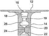
- FIG. 3is a side view of a two-way slit valve according to one of the embodiments of the present invention.
- FIG. 4is a cross-sectional view of the two-way valve shown in FIG. 3 ;
- FIG. 5is a close-up view of a portion of the two-way valve shown in FIG. 4 ;
- FIG. 6is a top view of the two-way valve according to another aspect of the present invention.
- FIG. 7is side view of a filler-tube according to another aspect of the present invention.
- FIG. 8is a side view of an inflation tip according to another aspect of the present invention:
- FIG. 9is a cross-sectional view of the inflation tip of FIG. 8 ;
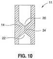
- FIG. 10is a cross-sectional view of a two-way valve according to another aspect of the present invention.
- FIG. 3A slit valve 10 in accordance with a first embodiment of this invention is shown in FIG. 3 .
- the valvecomprises a valve body 14 and a flange 12 .
- the end of the valve 10 on which the flange 12 is locatedwill be called the top of the valve and the opposite end the bottom.
- the valve 10is preferably formed of an elastomeric material such as silicone; however, other materials may be used without departing from the scope of this invention.
- the valve body 14is preferably molded in a substantially cylindrical shape. The cylindrical shape is preferred as it provides added rigidity and stiffness for the valve.
- FIGS. 4 and 5show cross-sectional views of the valve 10 .
- FIG. 6shows a top view of valve 10 .
- the flange surface 12 of the top of the valve 10there is an opening 16 through the flange 12 that is in communication with interior surfaces of the valve 10 .
- a first chamber 18Beneath the first chamber 18 is a neck 19 .
- the neck 19separates the first chamber 18 from a second chamber 26 .
- a concave surface 20is preferred because it provides guidance to a probe in the event that the sealing properties of valve 10 need to be overcome mechanically.
- the concave surface 20assists in the guidance of a probe (not shown) that can be used to force the valve to open and allow for reverse flow of fluid contained by the valve 10 .
- a slit 24in a substantially solid portion of the body 14 .
- the slit 24connects and is in fluid communication with a second surface 22 , which may be concave as shown, or flat.
- a second surface 22which may be concave as shown, or flat.
- fluidenters the balloon shell as it exits the bottom side of the slit 24 .
- the slit 24may be lubricated with silicone oil. The use of silicone oil eases the insertion of a removal tip (not shown) in instances where it is desired to overcome the sealing properties of the valve 10 , and serves to reduce the chance of cross-linking where the valve body 14 is made of silicone.
- FIG. 7depicts a filler tube 30 .
- the filler tubeis comprised of a long flexible tube 34 having a lumen therethrough, an injection tip 32 , and a connector 35 for connecting the filler tube to a fluid supply (not shown).
- the flexible tube 34may be provided with reference length markers 36 to provide medical personnel with a visual indication of the position of fill tube 30 inside the patient.
- the injection tip 32has an orifice 37 extending therethrough that allows for fluid communication through the flexible tube 34 , and the injection tip 32 .
- One of the ends of the injection tipmay be tapered into a wedge shape 38 having its smallest cross-section at the distal end of the injection tip 32 .
- the wedge shape 38assists in the insertion of the injection tip 32 into slit valve 10 .
- the injection tipmay include a reduced diameter portion 40 , and an insertion stop 42 for positively engaging the opening 16 of valve 10 .
- the other end of the injection tip 32is provided with barbs 44 to retain flexible tube 34 in fluid-tight engagement with the injection tip.
- the filler tube 30is connected to the valve 10 by inserting the injection tip 32 into opening 16 of the valve 10 .
- the injection tip 32upon full insertion into the valve, extends to a point approximately even with a top surface of the second chamber 26 .
- the substantial wedge shape 38 of the injection tipmatches the orientation of the first chamber 18 , and the narrow cross-sectional portion of the injection tip 32 is held firmly by the neck 19 of valve 10 to form a seal preventing the egress of fluid from the second chamber 26 into the first chamber 18 and out through the opening 16 .
- the insertion stop 42 on the injection tip 32prevents the injection tip from being inserted into the valve 10 beyond a pre-determined point.
- the insertion stop 42rests against the flange 12 of valve 10 .
- the opening 16is of a size that, upon insertion of the injection tip 32 , a second seal is formed by the interference of the flange 12 and the reduced diameter portion 40 of the injection tip. This second seal further insures that fluid does not exit the valve 10 and prevents other contaminants from entering the valve 10 .
- the valve 10may be attached to an inflatable medical device such as a gastric balloon, a mammary implant, such as a Becker-style breast implant, a tissue expander, or the like.
- an inflatable medical devicesuch as a gastric balloon, a mammary implant, such as a Becker-style breast implant, a tissue expander, or the like.
- Other non-inflatable applications of the valveinclude devices such as a shunt drug delivery or therapeutic delivery system, a feeding tube, or the like. Accordingly, these variations are contemplated within the scope of the present invention.
- the valve 10is attached to the shell substantially as shown in Prior Art FIGS. 1 and 2 .
- the flange surface 12is placed flush with the exterior surface of the balloon and may be covered by an elastomeric sheath material that bonds the components together forming an integral gastric balloon and valve combination.
- the gastric balloonis inserted into a patient in a deflated state and inflated after insertion.
- a fluidtypically sterile saline
- Other fluidsincluding air, silicone, pseudogel, oil, etc., may be used to fill an implant.
- the valve 10To inflate the gastric balloon, the valve 10 must have a slit 24 .
- the slit 24is preferably a single separation of two sides of the valve body 14 .
- the slit 24is formed during manufacturing by inserting a sharp thin tool (not shown) into the valve body 14 .
- the length of the slit 24is variable depending on the application of the valve and the desired opening pressure of the valve. In certain applications it may be necessary to insure that slit valve permits backflow more readily. In such instances, a shorter slit length would be used, whereas in instances where greater pressure must be contained by the valve, a longer slit length is desirable.
- the injection tip 32is inserted into the opening 16 of the flange 12 .
- the distal end of injection tip 32extends to form a seal with neck 19 .
- pressurized fluidis injected through the filler tube 30 and orifice 37 of the injection tip 32 .
- a higher pressureis created in the second chamber 26 having two effects. The first is to increase the sealing pressure of the neck 19 on the injection tip 32 .
- the second effectis to force the slit 24 to open.
- the decreased wall thickness of the valve body 14 in the area of the second chamber 26is more readily deformed by the pressurized fluid injected into the second chamber 26 than the area of the slit 24 .
- the increased pressurecauses the second chamber 26 to expand in a direction substantially perpendicular to the direction of the slit 24 .
- This expansionin turn causes the slit 24 to be opened and permits the flow of fluid from the second chamber 26 through the slit 24 and into the implant.
- the opening of the slitis assisted by the concave surface 20 .
- the second surface 22is also concave, sufficient pressure may be applied to the shell to overcome the backflow resistance of the valve to permit the flow of fluid through the slit 24 to the exterior of the implant. Due to the relative sizes of the second chamber 26 and the concave surface 22 , a far greater pressure is required to permit the backflow of fluid from the implant out of the valve than is required for inflation.
- the balloon or other implantmay also be deflated or reduced in volume by inserting a small diameter probe or tube completely through the valve and into the interior of the implant shell.
- Concave surface 20assists in guiding the small-diameter probe or tube into and through the valve body 14 .
- valve 10 and the filler tip 32when used in combination create a system that overcomes many of the shortcomings of the prior art.
- the injection tipis held firmly in place and is prevented from being forced out of the valve 10 during the injection of fluid through the valve 10 .
- withdrawal of the injection tip 32when desired by the user, is greatly eased requiring less than 4 lb (17.8 N) of force to remove the tip from a balloon filled to 700 cm 3 .
- the valve 10provides for a device that does not leak under normal operating conditions yet still allows for two-way flow.
- the valve of the present inventionallows continuous fluid flow at 30 psi (2.11 Kg/cm 2 ) and can safely withstand fluid fill pressures of up to 40 psi (2.81 Kg/cm 2 ) without damage to the valve.
- FIG. 10depicts another aspect of the present invention.
- FIG. 10shows a valve 11 having many of the features of the valve 10 shown in FIGS. 3-6 .
- Valve 11has a first concave surface 20 , a second concave surface 22 , and a slit 24 , all housed in a body 14 .
- the valve 11operates in a similar fashion to valve 10 .
- the slit 14Upon application of a predetermined fluid pressure to one of either the first or second concave surfaces, 20 or 22 , the slit 14 will open and allow fluid to pass. However, at pressures below the predetermined value, the slit valve insures that there is no fluid flow.
- the relative geometries of the concave surfaces 20 , 22 , the length of the slit 24 , and the valve body 14determine the opening pressure of the valve 11 and whether a greater pressure is required for flow in one direction compared to flow in the other direction. Such a valve would be useful in applications where the use of a flange 12 , as shown in FIG. 3 , is undesirable or unfeasible, for example in a feeding tube or a drug delivery shunt.
Landscapes
- Health & Medical Sciences (AREA)
- Heart & Thoracic Surgery (AREA)
- Public Health (AREA)
- Engineering & Computer Science (AREA)
- Veterinary Medicine (AREA)
- Biomedical Technology (AREA)
- Life Sciences & Earth Sciences (AREA)
- Animal Behavior & Ethology (AREA)
- General Health & Medical Sciences (AREA)
- Vascular Medicine (AREA)
- Hematology (AREA)
- Child & Adolescent Psychology (AREA)
- Obesity (AREA)
- Nursing (AREA)
- Orthopedic Medicine & Surgery (AREA)
- Anesthesiology (AREA)
- Pulmonology (AREA)
- Media Introduction/Drainage Providing Device (AREA)
- Infusion, Injection, And Reservoir Apparatuses (AREA)
- Surgical Instruments (AREA)
- Feeding And Controlling Fuel (AREA)
- Superconductors And Manufacturing Methods Therefor (AREA)
- Multiple-Way Valves (AREA)
- Prostheses (AREA)
- External Artificial Organs (AREA)
Abstract
Description
Claims (15)
Priority Applications (2)
| Application Number | Priority Date | Filing Date | Title |
|---|---|---|---|
| US16/030,098US10932935B2 (en) | 2003-06-20 | 2018-07-09 | Method of implanting an intragastric balloon |
| US17/189,516US20210177632A1 (en) | 2003-06-20 | 2021-03-02 | Method of implanting an intragastric balloon |
Applications Claiming Priority (6)
| Application Number | Priority Date | Filing Date | Title |
|---|---|---|---|
| US10/561,515US7749254B2 (en) | 2003-06-20 | 2003-06-20 | Two-way slit valve |
| PCT/US2003/019414WO2005007231A1 (en) | 2003-06-20 | 2003-06-20 | Two-way slit valve |
| US12/785,710US20100274194A1 (en) | 2003-06-20 | 2010-05-24 | Two-way slit valve |
| US13/667,617US9174033B2 (en) | 2003-06-20 | 2012-11-02 | Two-way slit valve |
| US14/700,092US10016294B2 (en) | 2003-06-20 | 2015-04-29 | Method of implanting an intragastric balloon |
| US16/030,098US10932935B2 (en) | 2003-06-20 | 2018-07-09 | Method of implanting an intragastric balloon |
Related Parent Applications (1)
| Application Number | Title | Priority Date | Filing Date |
|---|---|---|---|
| US14/700,092DivisionUS10016294B2 (en) | 2003-06-20 | 2015-04-29 | Method of implanting an intragastric balloon |
Related Child Applications (1)
| Application Number | Title | Priority Date | Filing Date |
|---|---|---|---|
| US17/189,516ContinuationUS20210177632A1 (en) | 2003-06-20 | 2021-03-02 | Method of implanting an intragastric balloon |
Publications (2)
| Publication Number | Publication Date |
|---|---|
| US20180311063A1 US20180311063A1 (en) | 2018-11-01 |
| US10932935B2true US10932935B2 (en) | 2021-03-02 |
Family
ID=34078447
Family Applications (7)
| Application Number | Title | Priority Date | Filing Date |
|---|---|---|---|
| US10/561,515Active2026-08-04US7749254B2 (en) | 2003-06-20 | 2003-06-20 | Two-way slit valve |
| US12/785,710AbandonedUS20100274194A1 (en) | 2003-06-20 | 2010-05-24 | Two-way slit valve |
| US13/667,617Expired - LifetimeUS9174033B2 (en) | 2003-06-20 | 2012-11-02 | Two-way slit valve |
| US14/699,911Expired - LifetimeUS10010440B2 (en) | 2003-06-20 | 2015-04-29 | Intragastric balloon system |
| US14/700,092Expired - LifetimeUS10016294B2 (en) | 2003-06-20 | 2015-04-29 | Method of implanting an intragastric balloon |
| US16/030,098Expired - Fee RelatedUS10932935B2 (en) | 2003-06-20 | 2018-07-09 | Method of implanting an intragastric balloon |
| US17/189,516AbandonedUS20210177632A1 (en) | 2003-06-20 | 2021-03-02 | Method of implanting an intragastric balloon |
Family Applications Before (5)
| Application Number | Title | Priority Date | Filing Date |
|---|---|---|---|
| US10/561,515Active2026-08-04US7749254B2 (en) | 2003-06-20 | 2003-06-20 | Two-way slit valve |
| US12/785,710AbandonedUS20100274194A1 (en) | 2003-06-20 | 2010-05-24 | Two-way slit valve |
| US13/667,617Expired - LifetimeUS9174033B2 (en) | 2003-06-20 | 2012-11-02 | Two-way slit valve |
| US14/699,911Expired - LifetimeUS10010440B2 (en) | 2003-06-20 | 2015-04-29 | Intragastric balloon system |
| US14/700,092Expired - LifetimeUS10016294B2 (en) | 2003-06-20 | 2015-04-29 | Method of implanting an intragastric balloon |
Family Applications After (1)
| Application Number | Title | Priority Date | Filing Date |
|---|---|---|---|
| US17/189,516AbandonedUS20210177632A1 (en) | 2003-06-20 | 2021-03-02 | Method of implanting an intragastric balloon |
Country Status (11)
| Country | Link |
|---|---|
| US (7) | US7749254B2 (en) |
| EP (1) | EP1638638B1 (en) |
| AT (1) | ATE438365T1 (en) |
| AU (2) | AU2003245593B2 (en) |
| BR (1) | BRPI0318347B8 (en) |
| CY (1) | CY1109467T1 (en) |
| DE (1) | DE60328723D1 (en) |
| DK (1) | DK1638638T3 (en) |
| ES (1) | ES2328567T3 (en) |
| PT (1) | PT1638638E (en) |
| WO (1) | WO2005007231A1 (en) |
Families Citing this family (116)
| Publication number | Priority date | Publication date | Assignee | Title |
|---|---|---|---|---|
| US6770080B2 (en) | 2001-04-26 | 2004-08-03 | Fenestra Medical, Inc. | Mechanically registered videoscopic myringotomy/tympanostomy tube placement system |
| US8614768B2 (en) | 2002-03-18 | 2013-12-24 | Raytheon Company | Miniaturized imaging device including GRIN lens optically coupled to SSID |
| US8845672B2 (en) | 2002-05-09 | 2014-09-30 | Reshape Medical, Inc. | Balloon system and methods for treating obesity |
| US7338433B2 (en) | 2002-08-13 | 2008-03-04 | Allergan, Inc. | Remotely adjustable gastric banding method |
| DK1553878T3 (en) | 2002-08-28 | 2010-05-31 | Allergan Inc | Fatigue resistant gastric banding device |
| US7749254B2 (en) | 2003-06-20 | 2010-07-06 | Allergan, Inc. | Two-way slit valve |
| JP2007527279A (en) | 2004-01-23 | 2007-09-27 | アラーガン、インコーポレイテッド | One-piece adjustable gastric band that can be fixed removably |
| CA2559056A1 (en) | 2004-03-08 | 2005-09-22 | Endoart S.A. | Closure system for tubular organs |
| EP1732635B1 (en) | 2004-03-18 | 2011-07-27 | Allergan, Inc. | Apparatus for volume adjustment of intragastric balloons |
| US9456915B2 (en)* | 2004-11-19 | 2016-10-04 | Fulfilium, Inc. | Methods, devices, and systems for obesity treatment |
| US8251888B2 (en) | 2005-04-13 | 2012-08-28 | Mitchell Steven Roslin | Artificial gastric valve |
| US20070100368A1 (en) | 2005-10-31 | 2007-05-03 | Quijano Rodolfo C | Intragastric space filler |
| US7798954B2 (en) | 2006-01-04 | 2010-09-21 | Allergan, Inc. | Hydraulic gastric band with collapsible reservoir |
| US8043206B2 (en) | 2006-01-04 | 2011-10-25 | Allergan, Inc. | Self-regulating gastric band with pressure data processing |
| CN101500517B (en)* | 2006-06-05 | 2012-03-07 | 乔斯·拉斐尔·加尔扎·艾尔瓦热兹 | Intragastric balloon assembly |
| US20070288033A1 (en)* | 2006-06-09 | 2007-12-13 | Allergan, Inc. | Intragastric balloon retrieval mechanisms |
| US9326877B2 (en) | 2006-09-29 | 2016-05-03 | Apollo Endosurgery, Inc. | Apparatus and method for intragastric balloon with in situ adjustment means |
| US7763033B2 (en) | 2006-10-18 | 2010-07-27 | Interlace Medical, Inc. | System and methods for preventing intravasation during intrauterine procedures |
| US8025656B2 (en) | 2006-11-07 | 2011-09-27 | Hologic, Inc. | Methods, systems and devices for performing gynecological procedures |
| US9392935B2 (en) | 2006-11-07 | 2016-07-19 | Hologic, Inc. | Methods for performing a medical procedure |
| JP5330222B2 (en)* | 2007-03-01 | 2013-10-30 | オリンパスメディカルシステムズ株式会社 | Lumen passage confirmation device, lumen passage confirmation method, and method for manufacturing lumen passage confirmation device |
| US9259233B2 (en) | 2007-04-06 | 2016-02-16 | Hologic, Inc. | Method and device for distending a gynecological cavity |
| US8951274B2 (en) | 2007-04-06 | 2015-02-10 | Hologic, Inc. | Methods of high rate, low profile tissue removal |
| US9095366B2 (en) | 2007-04-06 | 2015-08-04 | Hologic, Inc. | Tissue cutter with differential hardness |
| WO2008124650A1 (en) | 2007-04-06 | 2008-10-16 | Interlace Medical, Inc. | Method, system and device for tissue removal |
| US20080255601A1 (en)* | 2007-04-13 | 2008-10-16 | Allergan, Inc. | Apparatus and method for remote deflation of intragastric balloon |
| US8249700B2 (en) | 2007-04-19 | 2012-08-21 | Acclarent, Inc. | System and method for the simultaneous bilateral integrated tympanic drug delivery and guided treatment of target tissues within the ears |
| US8142469B2 (en) | 2007-06-25 | 2012-03-27 | Reshape Medical, Inc. | Gastric space filler device, delivery system, and related methods |
| WO2009023766A1 (en)* | 2007-08-15 | 2009-02-19 | Flodesign, Inc. | In vivo transportation of silicone gel for use in breast reconstruction and augmentation |
| CA2703486A1 (en)* | 2007-10-23 | 2009-04-30 | Allergan, Inc. | Pressure sensing intragastric balloon |
| US8192420B2 (en) | 2007-12-20 | 2012-06-05 | Acclarent, Inc. | Iontophoresis methods |
| AU2009257591A1 (en) | 2008-06-11 | 2009-12-17 | Allergan, Inc. | Implantable pump system |
| WO2009155441A2 (en) | 2008-06-18 | 2009-12-23 | Sterling Lc | Transparent endoscope head defining a focal length |
| WO2010014792A2 (en) | 2008-07-30 | 2010-02-04 | Sterling Lc | Method and device for incremental wavelength variation to analyze tissue |
| US8840602B2 (en) | 2008-07-31 | 2014-09-23 | Acclarent, Inc. | Systems and methods for anesthetizing ear tissue |
| US8452392B2 (en) | 2008-07-31 | 2013-05-28 | Acclarent, Inc. | Systems and methods for anesthetizing ear tissue |
| WO2010042493A1 (en) | 2008-10-06 | 2010-04-15 | Allergan, Inc. | Mechanical gastric band with cushions |
| US20100185049A1 (en) | 2008-10-22 | 2010-07-22 | Allergan, Inc. | Dome and screw valves for remotely adjustable gastric banding systems |
| WO2010053916A2 (en) | 2008-11-04 | 2010-05-14 | Sterling Lc | Method and device for wavelength shifted imaging |
| US9078783B2 (en)* | 2008-12-24 | 2015-07-14 | Acclarent, Inc. | Silent effusion removal |
| FR2941617B1 (en)* | 2009-02-04 | 2012-06-29 | Endalis | INTRA-GASTRIC BALLOON. |
| US9174031B2 (en) | 2009-03-13 | 2015-11-03 | Reshape Medical, Inc. | Device and method for deflation and removal of implantable and inflatable devices |
| US11903602B2 (en) | 2009-04-29 | 2024-02-20 | Hologic, Inc. | Uterine fibroid tissue removal device |
| US9770366B2 (en) | 2009-07-15 | 2017-09-26 | Tusker Medical, Inc. | Tympanic membrane pressure equalization tube delivery system |
| US9539146B2 (en) | 2009-07-15 | 2017-01-10 | Tusker Medical, Inc. | Trigger assembly for tympanostomy tube delivery device |
| WO2011011629A2 (en)* | 2009-07-22 | 2011-01-27 | Reshape Medical, Inc. | Retrieval mechanisms for implantable medical devices |
| US9050174B2 (en) | 2009-07-23 | 2015-06-09 | Reshape Medical, Inc. | Deflation and removal of implantable medical devices |
| US9604038B2 (en) | 2009-07-23 | 2017-03-28 | Reshape Medical, Inc. | Inflation and deflation mechanisms for inflatable medical devices |
| US8323249B2 (en) | 2009-08-14 | 2012-12-04 | The Regents Of The University Of Michigan | Integrated vascular delivery system |
| WO2011041728A2 (en)* | 2009-10-01 | 2011-04-07 | Jacobsen Stephen C | Needle delivered imaging device |
| WO2011041730A2 (en) | 2009-10-01 | 2011-04-07 | Jacobsen Stephen C | Light diffusion apparatus |
| WO2011041720A2 (en) | 2009-10-01 | 2011-04-07 | Jacobsen Stephen C | Method and apparatus for manipulating movement of a micro-catheter |
| US8828028B2 (en) | 2009-11-03 | 2014-09-09 | Raytheon Company | Suture device and method for closing a planar opening |
| EP2498668A4 (en) | 2009-11-13 | 2013-08-07 | Hologic Inc | Access system with removable outflow channel |
| WO2011097636A1 (en) | 2010-02-08 | 2011-08-11 | Reshape Medical, Inc. | Improved and enhanced aspiration processes and mechanisms for intragastric devices |
| EP2533846B1 (en) | 2010-02-08 | 2018-08-22 | ReShape Medical LLC | Materials and methods for improved intragastric balloon devices |
| US8758221B2 (en) | 2010-02-24 | 2014-06-24 | Apollo Endosurgery, Inc. | Source reservoir with potential energy for remotely adjustable gastric banding system |
| WO2011106637A1 (en) | 2010-02-25 | 2011-09-01 | Reshape Medical, Inc. | Improved and enhanced explant processes and mechanisms for intragastric devices |
| US8840541B2 (en) | 2010-02-25 | 2014-09-23 | Apollo Endosurgery, Inc. | Pressure sensing gastric banding system |
| EP2555705A4 (en) | 2010-04-06 | 2014-01-15 | Reshape Medical Inc | Inflation devices for intragastric devices with improved attachment and detachment and associated systems and methods |
| US9028394B2 (en) | 2010-04-29 | 2015-05-12 | Apollo Endosurgery, Inc. | Self-adjusting mechanical gastric band |
| US20110270024A1 (en) | 2010-04-29 | 2011-11-03 | Allergan, Inc. | Self-adjusting gastric band having various compliant components |
| US9044298B2 (en) | 2010-04-29 | 2015-06-02 | Apollo Endosurgery, Inc. | Self-adjusting gastric band |
| US20110270025A1 (en) | 2010-04-30 | 2011-11-03 | Allergan, Inc. | Remotely powered remotely adjustable gastric band system |
| WO2011146769A2 (en) | 2010-05-19 | 2011-11-24 | Tangent Medical Technologies Llc | Integrated vascular delivery system |
| US8814833B2 (en) | 2010-05-19 | 2014-08-26 | Tangent Medical Technologies Llc | Safety needle system operable with a medical device |
| US8517915B2 (en) | 2010-06-10 | 2013-08-27 | Allergan, Inc. | Remotely adjustable gastric banding system |
| US9526648B2 (en) | 2010-06-13 | 2016-12-27 | Synerz Medical, Inc. | Intragastric device for treating obesity |
| US10420665B2 (en) | 2010-06-13 | 2019-09-24 | W. L. Gore & Associates, Inc. | Intragastric device for treating obesity |
| US10010439B2 (en) | 2010-06-13 | 2018-07-03 | Synerz Medical, Inc. | Intragastric device for treating obesity |
| US8628554B2 (en) | 2010-06-13 | 2014-01-14 | Virender K. Sharma | Intragastric device for treating obesity |
| US20120059216A1 (en) | 2010-09-07 | 2012-03-08 | Allergan, Inc. | Remotely adjustable gastric banding system |
| US8870966B2 (en) | 2010-10-18 | 2014-10-28 | Apollo Endosurgery, Inc. | Intragastric balloon for treating obesity |
| US9463107B2 (en) | 2010-10-18 | 2016-10-11 | Apollo Endosurgery, Inc. | Variable size intragastric implant devices |
| ES2566498T3 (en) | 2010-10-18 | 2016-04-13 | Apollo Endosurgery, Inc. | Intragastric implants with duodenal anchors |
| ES2565348T3 (en) | 2010-10-18 | 2016-04-04 | Apollo Endosurgery, Inc. | Intragastric implant reagent devices |
| US9498365B2 (en) | 2010-10-19 | 2016-11-22 | Apollo Endosurgery, Inc. | Intragastric implants with multiple fluid chambers |
| US9398969B2 (en) | 2010-10-19 | 2016-07-26 | Apollo Endosurgery, Inc. | Upper stomach gastric implants |
| WO2012054522A2 (en) | 2010-10-19 | 2012-04-26 | Allergan, Inc. | Anchored non-piercing duodenal sleeve and delivery systems |
| US9198790B2 (en) | 2010-10-19 | 2015-12-01 | Apollo Endosurgery, Inc. | Upper stomach gastric implants |
| US8920447B2 (en) | 2010-10-19 | 2014-12-30 | Apollo Endosurgery, Inc. | Articulated gastric implant clip |
| US8864840B2 (en) | 2010-10-19 | 2014-10-21 | Apollo Endosurgery, Inc. | Intragastric implants with collapsible frames |
| US8961393B2 (en) | 2010-11-15 | 2015-02-24 | Apollo Endosurgery, Inc. | Gastric band devices and drive systems |
| US8888732B2 (en) | 2011-03-11 | 2014-11-18 | Apollo Endosurgery, Inc. | Intraluminal sleeve with active agents |
| WO2012158972A2 (en)* | 2011-05-17 | 2012-11-22 | Endobese, Inc. | Method and apparatus for buoyant gastric implant |
| CA2843147C (en) | 2011-07-25 | 2020-04-14 | Acclarent, Inc. | Personalizable system and method for anesthetizing the tympanic membrane |
| US8876694B2 (en) | 2011-12-07 | 2014-11-04 | Apollo Endosurgery, Inc. | Tube connector with a guiding tip |
| US8961394B2 (en) | 2011-12-20 | 2015-02-24 | Apollo Endosurgery, Inc. | Self-sealing fluid joint for use with a gastric band |
| ES2608629T3 (en) | 2012-02-21 | 2017-04-12 | Allurion Technologies, Inc. | Devices for deployment and release of a temporary implant in the body |
| US10182932B2 (en) | 2012-02-21 | 2019-01-22 | Allurion Technologies, Inc. | Methods and devices for deploying and releasing a temporary implant within the body |
| US9849018B2 (en) | 2012-02-21 | 2017-12-26 | Allurion Technologies, Inc. | Ingestible delivery systems and methods |
| US9364648B2 (en) | 2012-05-30 | 2016-06-14 | Tusker Medical, Inc. | Adhesive earplugs useful for sealing the ear canal |
| US10465809B2 (en)* | 2013-02-22 | 2019-11-05 | Nsi International, Inc. | Valve assembly for expandable bladder and method of manufacturing the same |
| US9681891B2 (en) | 2013-03-14 | 2017-06-20 | Tusker Medical, Inc. | Tympanostomy tube delivery device with cutting dilator |
| US9320652B2 (en) | 2013-03-14 | 2016-04-26 | Tusker Medical, Inc. | Features to improve and sense tympanic membrane apposition by tympanostomy tube delivery instrument |
| US10130808B2 (en) | 2013-03-14 | 2018-11-20 | Tusker Medical, Inc. | System and method for providing iontophoresis at tympanic membrane |
| EP3378525B1 (en) | 2013-03-16 | 2019-08-28 | Poly Medicure Limited | Transfer device valve |
| RU2530773C1 (en)* | 2013-08-26 | 2014-10-10 | Закрытое акционерное общество "МедСил" | Overweight correction device |
| CA2937744C (en) | 2014-02-04 | 2022-08-09 | Icu Medical, Inc. | Self-priming systems and methods |
| US20160038341A1 (en) | 2014-08-08 | 2016-02-11 | Acclarent, Inc. | Tympanostomy tube delivery device with elastomeric brake |
| US10195086B2 (en) | 2014-08-11 | 2019-02-05 | Tusker Medical, Inc. | Tympanostomy tube delivery device with rotatable |
| US9833359B2 (en) | 2014-08-12 | 2017-12-05 | Tusker Medical, Inc. | Tympanostomy tube delivery device with cutter force clutch |
| US9833360B2 (en) | 2014-08-12 | 2017-12-05 | Tusker Medical, Inc. | Tympanostomy tube delivery device with replaceable shaft portion |
| AU2016229120A1 (en)* | 2015-03-09 | 2017-10-19 | Allurion Technologies, Inc. | Methods and devices for deploying and releasing a temporary implant within the body |
| US10016304B2 (en) | 2015-07-16 | 2018-07-10 | Tusker Medical, Inc. | Earplug assembly for iontophoresis system |
| US10779980B2 (en) | 2016-04-27 | 2020-09-22 | Synerz Medical, Inc. | Intragastric device for treating obesity |
| IT201600084458A1 (en)* | 2016-08-10 | 2018-02-10 | Euromedical S R L | INTRAGASTRIC BALLOON AND ITS MANUFACTURING METHOD |
| US10537454B2 (en)* | 2017-06-16 | 2020-01-21 | Proximate Concepts Llc | Electrophysiologically active transducer intragastric balloon system and method |
| US10238516B1 (en)* | 2017-11-01 | 2019-03-26 | Barix Medical Corp. | Simplified implantable gastric balloon system with self deflating timer |
| EP4344724A3 (en) | 2018-02-26 | 2024-08-21 | Allurion Technologies, LLC | Automatic-sealing balloon-filling catheter system |
| CN112638464B (en) | 2018-07-06 | 2021-12-14 | 阿勒里恩科技公司 | Binary fluid control valve system |
| EP3886774A4 (en) | 2018-12-13 | 2022-09-28 | Allurion Technologies, Inc. | Enhanced fluid delivery system |
| WO2021051182A1 (en)* | 2019-09-20 | 2021-03-25 | Salles De Almeida Leonardo | Devices and method for bi-directional adjustment of intragastric balloons, and shut-off valve |
| US20250107806A1 (en)* | 2021-08-03 | 2025-04-03 | Basilios Eleftherios Sideris | Medical device and method for safely closing, isolating, or adjusting the volume of a structure in the human body |
| US12246163B2 (en) | 2023-04-12 | 2025-03-11 | Allurion Technologies, Inc. | Automatic-sealing balloon-filling catheter system |
| US12245962B2 (en) | 2023-04-12 | 2025-03-11 | Allurion Technologies, Inc. | Balloon sealing and fill valve |
Citations (11)
| Publication number | Priority date | Publication date | Assignee | Title |
|---|---|---|---|---|
| US563287A (en)* | 1896-07-07 | Island | ||
| US4364392A (en)* | 1980-12-04 | 1982-12-21 | Wisconsin Alumni Research Foundation | Detachable balloon catheter |
| US4612960A (en)* | 1985-02-21 | 1986-09-23 | Vernay Laboratories, Inc. | Valve assembly |
| US4739758A (en)* | 1986-05-19 | 1988-04-26 | Criticare Systems, Inc. | Apparatus for stomach cavity reduction |
| US5113911A (en)* | 1989-12-11 | 1992-05-19 | Advantec Corp. | Pressure actuated elastomeric valve |
| US5181921A (en)* | 1990-05-25 | 1993-01-26 | Kaken Co., Ltd. | Detachable balloon with two self-sealing valves |
| US5300034A (en)* | 1992-07-29 | 1994-04-05 | Minnesota Mining And Manufacturing Company | Iv injection site for the reception of a blunt cannula |
| US5820614A (en)* | 1996-03-15 | 1998-10-13 | Becton Dickinson And Company | Disconnect for medical access devices |
| US5823852A (en)* | 1997-05-29 | 1998-10-20 | Chu; Chia-Hui | Water bag type brassiere padding with a valve |
| US20040254625A1 (en)* | 2003-06-13 | 2004-12-16 | Trivascular, Inc. | Inflatable implant |
| US20070118168A1 (en)* | 2001-12-28 | 2007-05-24 | Lointier Patrice H | Multiple-pouch intragastric balloons, surgical device for expanding said balloon and method for making same |
Family Cites Families (57)
| Publication number | Priority date | Publication date | Assignee | Title |
|---|---|---|---|---|
| US1702974A (en)* | 1928-05-12 | 1929-02-19 | Spalding & Bros Ag | Collapsible valve and method of making same |
| GB1199498A (en)* | 1967-03-29 | 1970-07-22 | Latex Products Proprietary Ltd | Non-Return Valve for Medical Uses. |
| US3919724A (en)* | 1974-06-07 | 1975-11-18 | Medical Eng Corp | Implantable prosthesis having a self-sealing valve |
| US4436519A (en)* | 1981-05-28 | 1984-03-13 | Argon Medical Corp. | Removable hemostasis valve |
| US4485805A (en)* | 1982-08-24 | 1984-12-04 | Gunther Pacific Limited Of Hong Kong | Weight loss device and method |
| US4430392A (en)* | 1983-02-11 | 1984-02-07 | Honeywell Inc. | Heat activated vent |
| US4607618A (en)* | 1983-02-23 | 1986-08-26 | Angelchik Jean P | Method for treatment of morbid obesity |
| US4653477A (en)* | 1984-09-13 | 1987-03-31 | Olympus Optical Co., Ltd. | Endoscope forceps stopcock |
| US4636213A (en)* | 1985-01-24 | 1987-01-13 | Pakiam Anthony I | Implantable prosthesis |
| US4694827A (en)* | 1986-01-14 | 1987-09-22 | Weiner Brian C | Inflatable gastric device for treating obesity and method of using the same |
| US4773908A (en)* | 1986-12-18 | 1988-09-27 | Hilton Becker | Filling tube and seal construction for inflatable implant |
| US5251873B1 (en)* | 1992-06-04 | 1995-05-02 | Vernay Laboratories | Medical coupling site. |
| US4930535A (en)* | 1987-05-14 | 1990-06-05 | Mcghan Medical Corporation | Folding leaf valve and method of making |
| US5084061A (en)* | 1987-09-25 | 1992-01-28 | Gau Fred C | Intragastric balloon with improved valve locating means |
| DE8804765U1 (en) | 1988-04-12 | 1989-05-11 | Witzel, Lothar, Prof. Dr., 1000 Berlin | Gastric balloon for weight loss |
| IE62767B1 (en)* | 1989-03-17 | 1995-02-22 | Baxter Int | Pre-slit injection site and tapered cannula |
| US5113571A (en)* | 1990-01-29 | 1992-05-19 | Manska Wayne E | Method of manufacturing a connector for medical devices |
| US5263930A (en)* | 1990-03-01 | 1993-11-23 | William D. Ensminger | Implantable access devices |
| US5205834A (en)* | 1990-09-04 | 1993-04-27 | Moorehead H Robert | Two-way outdwelling slit valving of medical liquid flow through a cannula and methods |
| US5211371A (en)* | 1991-07-22 | 1993-05-18 | Advanced Control Technologies, Inc. | Linearly actuated valve |
| DE4127628C1 (en)* | 1991-08-21 | 1992-07-23 | Vygon Gmbh & Co Kg, 5100 Aachen, De | |
| US5250029A (en)* | 1991-11-06 | 1993-10-05 | Edward Lin | Zero-residual zero-tip balloon catheter |
| US5269764A (en)* | 1992-08-21 | 1993-12-14 | Devices For Vascular Intervention, Inc. | Hemostatic gasket and valve assembly |
| JPH07163666A (en)* | 1993-12-16 | 1995-06-27 | Terumo Corp | Connector |
| AU1938395A (en)* | 1994-03-04 | 1995-09-18 | Mentor Corporation | Self-sealing injection sites and method of manufacture |
| US5470319A (en) | 1994-06-20 | 1995-11-28 | Critical Device Corporation | Needleless injection site |
| US5507808A (en)* | 1994-10-26 | 1996-04-16 | Becker; Hilton | Filling tube and seal construction |
| US5513630A (en)* | 1995-03-08 | 1996-05-07 | Century; Theodore J. | Powder dispenser |
| US5771902A (en)* | 1995-09-25 | 1998-06-30 | Regents Of The University Of California | Micromachined actuators/sensors for intratubular positioning/steering |
| DE19749011A1 (en)* | 1996-11-19 | 1998-05-20 | Lang Volker | Micro=valve for one time use has opening closed by plug mounted on resistance plate |
| US5843046A (en)* | 1997-05-29 | 1998-12-01 | Paul J. Motisi | Catheter apparatus |
| US6039748A (en)* | 1997-08-05 | 2000-03-21 | Femrx, Inc. | Disposable laparoscopic morcellator |
| US5916198A (en)* | 1997-08-05 | 1999-06-29 | Femrx, Inc. | Non-binding surgical valve |
| US6419699B1 (en)* | 1999-04-14 | 2002-07-16 | Mcghan Medical Corporation | Universal implant fill connector |
| DE19925324C1 (en)* | 1999-06-02 | 2001-01-25 | Winter & Ibe Olympus | Trocar sleeve with duckbill valve |
| US6364867B2 (en)* | 1999-07-01 | 2002-04-02 | Catheter Innovations, Inc. | Anti-clotting methods and apparatus for indwelling catheter tubes |
| US6322572B1 (en)* | 1999-08-10 | 2001-11-27 | Neurovasx, Inc. | Thrombus macerator catheter |
| US6733513B2 (en)* | 1999-11-04 | 2004-05-11 | Advanced Bioprosthetic Surfaces, Ltd. | Balloon catheter having metal balloon and method of making same |
| MXPA00001922A (en)* | 2000-02-24 | 2002-03-08 | De Hayos Garza Andres | Percutaneous intra-gastric balloon catheter for obesity treatment. |
| US6503264B1 (en)* | 2000-03-03 | 2003-01-07 | Bioenterics Corporation | Endoscopic device for removing an intragastric balloon |
| US7033373B2 (en)* | 2000-11-03 | 2006-04-25 | Satiety, Inc. | Method and device for use in minimally invasive placement of space-occupying intragastric devices |
| US6579301B1 (en)* | 2000-11-17 | 2003-06-17 | Syntheon, Llc | Intragastric balloon device adapted to be repeatedly varied in volume without external assistance |
| CN1329719C (en)* | 2000-12-12 | 2007-08-01 | 迷你米特公司 | Digital Sensors and Body Temperature Monitors for Tiny Medical Thermometers |
| US6616626B2 (en)* | 2000-12-21 | 2003-09-09 | Scimed Life Systems, Inc. | Infusion devices and method |
| EP1366716B1 (en)* | 2001-03-09 | 2005-04-27 | José Rafael Garza Alvarez | Intragastric balloon assembly |
| US7020531B1 (en)* | 2001-05-01 | 2006-03-28 | Intrapace, Inc. | Gastric device and suction assisted method for implanting a device on a stomach wall |
| US6840257B2 (en)* | 2001-05-08 | 2005-01-11 | Alberto Arena | Proportional valve with shape memory alloy actuator |
| US6733512B2 (en)* | 2002-03-07 | 2004-05-11 | Mcghan Jim J. | Self-deflating intragastric balloon |
| US6746460B2 (en)* | 2002-08-07 | 2004-06-08 | Satiety, Inc. | Intra-gastric fastening devices |
| US7214233B2 (en)* | 2002-08-30 | 2007-05-08 | Satiety, Inc. | Methods and devices for maintaining a space occupying device in a relatively fixed location within a stomach |
| US7037344B2 (en)* | 2002-11-01 | 2006-05-02 | Valentx, Inc. | Apparatus and methods for treatment of morbid obesity |
| US7749254B2 (en) | 2003-06-20 | 2010-07-06 | Allergan, Inc. | Two-way slit valve |
| US9498366B2 (en)* | 2003-07-28 | 2016-11-22 | Baronova, Inc. | Devices and methods for pyloric anchoring |
| WO2005107641A2 (en) | 2004-05-03 | 2005-11-17 | Fulfillium, Inc. | Method and system for gastric volume control |
| US7699863B2 (en) | 2005-03-01 | 2010-04-20 | Tulip Medical Ltd. | Bioerodible self-deployable intragastric implants |
| US8216266B2 (en)* | 2005-06-16 | 2012-07-10 | Hively Robert L | Gastric bariatric apparatus with selective inflation and safety features |
| US20070016262A1 (en)* | 2005-07-13 | 2007-01-18 | Betastim, Ltd. | Gi and pancreatic device for treating obesity and diabetes |
- 2003
- 2003-06-20USUS10/561,515patent/US7749254B2/enactiveActive
- 2003-06-20AUAU2003245593Apatent/AU2003245593B2/ennot_activeExpired
- 2003-06-20ESES03739221Tpatent/ES2328567T3/ennot_activeExpired - Lifetime
- 2003-06-20DKDK03739221Tpatent/DK1638638T3/enactive
- 2003-06-20BRBRPI0318347Apatent/BRPI0318347B8/ennot_activeIP Right Cessation
- 2003-06-20DEDE60328723Tpatent/DE60328723D1/ennot_activeExpired - Lifetime
- 2003-06-20PTPT03739221Tpatent/PT1638638E/enunknown
- 2003-06-20EPEP03739221Apatent/EP1638638B1/ennot_activeExpired - Lifetime
- 2003-06-20ATAT03739221Tpatent/ATE438365T1/enactive
- 2003-06-20WOPCT/US2003/019414patent/WO2005007231A1/enactiveApplication Filing
- 2009
- 2009-10-13CYCY20091101049Tpatent/CY1109467T1/enunknown
- 2010
- 2010-05-24USUS12/785,710patent/US20100274194A1/ennot_activeAbandoned
- 2010-09-01AUAU2010214763Apatent/AU2010214763B2/ennot_activeExpired
- 2012
- 2012-11-02USUS13/667,617patent/US9174033B2/ennot_activeExpired - Lifetime
- 2015
- 2015-04-29USUS14/699,911patent/US10010440B2/ennot_activeExpired - Lifetime
- 2015-04-29USUS14/700,092patent/US10016294B2/ennot_activeExpired - Lifetime
- 2018
- 2018-07-09USUS16/030,098patent/US10932935B2/ennot_activeExpired - Fee Related
- 2021
- 2021-03-02USUS17/189,516patent/US20210177632A1/ennot_activeAbandoned
Patent Citations (11)
| Publication number | Priority date | Publication date | Assignee | Title |
|---|---|---|---|---|
| US563287A (en)* | 1896-07-07 | Island | ||
| US4364392A (en)* | 1980-12-04 | 1982-12-21 | Wisconsin Alumni Research Foundation | Detachable balloon catheter |
| US4612960A (en)* | 1985-02-21 | 1986-09-23 | Vernay Laboratories, Inc. | Valve assembly |
| US4739758A (en)* | 1986-05-19 | 1988-04-26 | Criticare Systems, Inc. | Apparatus for stomach cavity reduction |
| US5113911A (en)* | 1989-12-11 | 1992-05-19 | Advantec Corp. | Pressure actuated elastomeric valve |
| US5181921A (en)* | 1990-05-25 | 1993-01-26 | Kaken Co., Ltd. | Detachable balloon with two self-sealing valves |
| US5300034A (en)* | 1992-07-29 | 1994-04-05 | Minnesota Mining And Manufacturing Company | Iv injection site for the reception of a blunt cannula |
| US5820614A (en)* | 1996-03-15 | 1998-10-13 | Becton Dickinson And Company | Disconnect for medical access devices |
| US5823852A (en)* | 1997-05-29 | 1998-10-20 | Chu; Chia-Hui | Water bag type brassiere padding with a valve |
| US20070118168A1 (en)* | 2001-12-28 | 2007-05-24 | Lointier Patrice H | Multiple-pouch intragastric balloons, surgical device for expanding said balloon and method for making same |
| US20040254625A1 (en)* | 2003-06-13 | 2004-12-16 | Trivascular, Inc. | Inflatable implant |
Also Published As
| Publication number | Publication date |
|---|---|
| ATE438365T1 (en) | 2009-08-15 |
| AU2003245593B2 (en) | 2010-06-03 |
| US10016294B2 (en) | 2018-07-10 |
| PT1638638E (en) | 2009-09-09 |
| WO2005007231A1 (en) | 2005-01-27 |
| AU2010214763B2 (en) | 2013-03-07 |
| EP1638638B1 (en) | 2009-08-05 |
| US20150230957A1 (en) | 2015-08-20 |
| AU2010214763A1 (en) | 2010-09-23 |
| US20180311063A1 (en) | 2018-11-01 |
| DE60328723D1 (en) | 2009-09-17 |
| BRPI0318347B1 (en) | 2015-10-06 |
| DK1638638T3 (en) | 2009-11-23 |
| US7749254B2 (en) | 2010-07-06 |
| US20100274194A1 (en) | 2010-10-28 |
| US20210177632A1 (en) | 2021-06-17 |
| EP1638638A1 (en) | 2006-03-29 |
| US20060142700A1 (en) | 2006-06-29 |
| AU2003245593A1 (en) | 2005-02-04 |
| US9174033B2 (en) | 2015-11-03 |
| HK1082445A1 (en) | 2006-06-09 |
| US20150230956A1 (en) | 2015-08-20 |
| EP1638638A4 (en) | 2008-03-05 |
| BR0318347A (en) | 2006-07-11 |
| CY1109467T1 (en) | 2014-08-13 |
| US20130103071A1 (en) | 2013-04-25 |
| ES2328567T3 (en) | 2009-11-16 |
| US10010440B2 (en) | 2018-07-03 |
| BRPI0318347B8 (en) | 2021-06-22 |
Similar Documents
| Publication | Publication Date | Title |
|---|---|---|
| US20210177632A1 (en) | Method of implanting an intragastric balloon | |
| US4773908A (en) | Filling tube and seal construction for inflatable implant | |
| CN101203187B (en) | Device for gastric feeding and drainage via an artificial stoma | |
| US8075521B2 (en) | Catheter | |
| US4734094A (en) | Catheter and method for cholangiography | |
| US7488336B2 (en) | Single control gastric band | |
| US4246893A (en) | Inflatable gastric device for treating obesity | |
| US4634443A (en) | Single circuit elastofluidic sphincter | |
| JP5059875B2 (en) | Guide tube with puncture balloon | |
| DE60112554T2 (en) | INTRAGASTRAL DEVICE FOR THE TREATMENT OF MORBIDEN FATSUCHT | |
| US4930535A (en) | Folding leaf valve and method of making | |
| CN104968304B (en) | Expansion type blocking device for sphincter of pylorus | |
| US20170368320A1 (en) | Catheter and method of insertion | |
| US20090112183A1 (en) | Medical devices and methods of use | |
| US20080262529A1 (en) | Gastric Balloon Devices and Methods of Use | |
| WO2004067080A1 (en) | Endoscope-equipped puncture balloon | |
| US20050283180A1 (en) | Fluid adjustable band | |
| HK1082445B (en) | Two-way slit valve | |
| RU2338561C2 (en) | Valve with groove and medical apparatus for adiposity treatment | |
| KR102393312B1 (en) | Medical catheter | |
| US20190159972A1 (en) | Enteral feeding satiation device |
Legal Events
| Date | Code | Title | Description |
|---|---|---|---|
| FEPP | Fee payment procedure | Free format text:ENTITY STATUS SET TO UNDISCOUNTED (ORIGINAL EVENT CODE: BIG.); ENTITY STATUS OF PATENT OWNER: SMALL ENTITY | |
| FEPP | Fee payment procedure | Free format text:ENTITY STATUS SET TO SMALL (ORIGINAL EVENT CODE: SMAL); ENTITY STATUS OF PATENT OWNER: SMALL ENTITY | |
| STPP | Information on status: patent application and granting procedure in general | Free format text:DOCKETED NEW CASE - READY FOR EXAMINATION | |
| AS | Assignment | Owner name:SOLAR CAPITAL LTD., AS COLLATERAL AGENT, NEW YORK Free format text:INTELLECTUAL PROPERTY SECURITY AGREEMENT;ASSIGNOR:APOLLO ENDOSURGERY, INC.;REEL/FRAME:048885/0621 Effective date:20190315 | |
| STPP | Information on status: patent application and granting procedure in general | Free format text:NON FINAL ACTION MAILED | |
| AS | Assignment | Owner name:ALLERGAN, INC., CALIFORNIA Free format text:ASSIGNMENT OF ASSIGNORS INTEREST;ASSIGNORS:SOBELMAN, OWEN SHAWN;BIRK, JANEL A.;SIGNING DATES FROM 20080722 TO 20080724;REEL/FRAME:053928/0806 Owner name:APOLLO ENDOSURGERY, INC., TEXAS Free format text:ASSIGNMENT OF ASSIGNORS INTEREST;ASSIGNOR:ALLERGAN, INC.;REEL/FRAME:053928/0953 Effective date:20131202 | |
| STPP | Information on status: patent application and granting procedure in general | Free format text:NOTICE OF ALLOWANCE MAILED -- APPLICATION RECEIVED IN OFFICE OF PUBLICATIONS | |
| STCF | Information on status: patent grant | Free format text:PATENTED CASE | |
| AS | Assignment | Owner name:INNOVATUS LIFE SCIENCES LENDING FUND I, LP, NEW YORK Free format text:SECURITY INTEREST;ASSIGNORS:APOLLO ENDOSURGERY, INC.;APOLLO ENDOSURGERY US, INC. (F/K/A LPATH, INC.);REEL/FRAME:058980/0199 Effective date:20211221 | |
| AS | Assignment | Owner name:LPATH THERAPEUTICS INC., TEXAS Free format text:RELEASE BY SECURED PARTY;ASSIGNOR:SLR INVESTMENT CORP. (F/K/A SOLAR CAPITAL LTD.);REEL/FRAME:058599/0297 Effective date:20211221 Owner name:APOLLO ENDOSURGERY, INC., TEXAS Free format text:RELEASE BY SECURED PARTY;ASSIGNOR:SLR INVESTMENT CORP. (F/K/A SOLAR CAPITAL LTD.);REEL/FRAME:058599/0297 Effective date:20211221 Owner name:APOLLO ENDOSURGERY INTERNATIONAL, LLC, TEXAS Free format text:RELEASE BY SECURED PARTY;ASSIGNOR:SLR INVESTMENT CORP. (F/K/A SOLAR CAPITAL LTD.);REEL/FRAME:058599/0297 Effective date:20211221 Owner name:APOLLO ENDOSURGERY US, INC., TEXAS Free format text:RELEASE BY SECURED PARTY;ASSIGNOR:SLR INVESTMENT CORP. (F/K/A SOLAR CAPITAL LTD.);REEL/FRAME:058599/0297 Effective date:20211221 | |
| AS | Assignment | Owner name:INNOVATUS LIFE SCIENCES LENDING FUND I, LP, NEW YORK Free format text:TERMINATION AND RELEASE OF INTELLECTUAL PROPERTY SECURITY AGREEMENT;ASSIGNORS:APOLLO ENDOSURGERY, INC.;APOLLO ENDOSURGERY US, INC.;APOLLO ENDOSURGERY INTERNATIONAL, LLC;AND OTHERS;REEL/FRAME:063264/0046 Effective date:20230404 | |
| FEPP | Fee payment procedure | Free format text:ENTITY STATUS SET TO UNDISCOUNTED (ORIGINAL EVENT CODE: BIG.); ENTITY STATUS OF PATENT OWNER: LARGE ENTITY | |
| AS | Assignment | Owner name:BOSTON SCIENTIFIC SCIMED, INC., MINNESOTA Free format text:ASSIGNMENT OF ASSIGNORS INTEREST;ASSIGNOR:APOLLO ENDOSURGERY, INC.;REEL/FRAME:066128/0812 Effective date:20230404 Owner name:APOLLO ENDOSURGERY, INC., TEXAS Free format text:ASSIGNMENT OF ASSIGNORS INTEREST;ASSIGNOR:APOLLO ENDOSURGERY US, INC.;REEL/FRAME:066128/0655 Effective date:20230404 | |
| AS | Assignment | Owner name:APOLLO ENDOSURGERY US, INC., TEXAS Free format text:CHANGE OF NAME;ASSIGNOR:APOLLO ENDOSURGERY, INC.;REEL/FRAME:066660/0792 Effective date:20161229 | |
| FEPP | Fee payment procedure | Free format text:MAINTENANCE FEE REMINDER MAILED (ORIGINAL EVENT CODE: REM.); ENTITY STATUS OF PATENT OWNER: LARGE ENTITY | |
| LAPS | Lapse for failure to pay maintenance fees | Free format text:PATENT EXPIRED FOR FAILURE TO PAY MAINTENANCE FEES (ORIGINAL EVENT CODE: EXP.); ENTITY STATUS OF PATENT OWNER: LARGE ENTITY | |
| STCH | Information on status: patent discontinuation | Free format text:PATENT EXPIRED DUE TO NONPAYMENT OF MAINTENANCE FEES UNDER 37 CFR 1.362 | |
| FP | Lapsed due to failure to pay maintenance fee | Effective date:20250302 |