US10932769B2 - System and method for all-inside suture fixation for implant attachment and soft tissue repair - Google Patents
System and method for all-inside suture fixation for implant attachment and soft tissue repairDownload PDFInfo
- Publication number
- US10932769B2 US10932769B2US15/604,071US201715604071AUS10932769B2US 10932769 B2US10932769 B2US 10932769B2US 201715604071 AUS201715604071 AUS 201715604071AUS 10932769 B2US10932769 B2US 10932769B2
- Authority
- US
- United States
- Prior art keywords
- anchor
- needle
- pusher
- actuator
- housing
- Prior art date
- Legal status (The legal status is an assumption and is not a legal conclusion. Google has not performed a legal analysis and makes no representation as to the accuracy of the status listed.)
- Active, expires
Links
Images


Classifications
- A—HUMAN NECESSITIES
- A61—MEDICAL OR VETERINARY SCIENCE; HYGIENE
- A61B—DIAGNOSIS; SURGERY; IDENTIFICATION
- A61B17/00—Surgical instruments, devices or methods
- A61B17/04—Surgical instruments, devices or methods for suturing wounds; Holders or packages for needles or suture materials
- A61B17/0401—Suture anchors, buttons or pledgets, i.e. means for attaching sutures to bone, cartilage or soft tissue; Instruments for applying or removing suture anchors
- A—HUMAN NECESSITIES
- A61—MEDICAL OR VETERINARY SCIENCE; HYGIENE
- A61B—DIAGNOSIS; SURGERY; IDENTIFICATION
- A61B17/00—Surgical instruments, devices or methods
- A61B17/04—Surgical instruments, devices or methods for suturing wounds; Holders or packages for needles or suture materials
- A61B17/0469—Suturing instruments for use in minimally invasive surgery, e.g. endoscopic surgery
- A—HUMAN NECESSITIES
- A61—MEDICAL OR VETERINARY SCIENCE; HYGIENE
- A61B—DIAGNOSIS; SURGERY; IDENTIFICATION
- A61B17/00—Surgical instruments, devices or methods
- A61B17/04—Surgical instruments, devices or methods for suturing wounds; Holders or packages for needles or suture materials
- A61B17/06—Needles ; Sutures; Needle-suture combinations; Holders or packages for needles or suture materials
- A61B17/06066—Needles, e.g. needle tip configurations
- A61B17/06109—Big needles, either gripped by hand or connectable to a handle
- A—HUMAN NECESSITIES
- A61—MEDICAL OR VETERINARY SCIENCE; HYGIENE
- A61B—DIAGNOSIS; SURGERY; IDENTIFICATION
- A61B17/00—Surgical instruments, devices or methods
- A61B17/04—Surgical instruments, devices or methods for suturing wounds; Holders or packages for needles or suture materials
- A61B17/0401—Suture anchors, buttons or pledgets, i.e. means for attaching sutures to bone, cartilage or soft tissue; Instruments for applying or removing suture anchors
- A61B2017/0404—Buttons
- A—HUMAN NECESSITIES
- A61—MEDICAL OR VETERINARY SCIENCE; HYGIENE
- A61B—DIAGNOSIS; SURGERY; IDENTIFICATION
- A61B17/00—Surgical instruments, devices or methods
- A61B17/04—Surgical instruments, devices or methods for suturing wounds; Holders or packages for needles or suture materials
- A61B17/0401—Suture anchors, buttons or pledgets, i.e. means for attaching sutures to bone, cartilage or soft tissue; Instruments for applying or removing suture anchors
- A61B2017/0409—Instruments for applying suture anchors
- A—HUMAN NECESSITIES
- A61—MEDICAL OR VETERINARY SCIENCE; HYGIENE
- A61B—DIAGNOSIS; SURGERY; IDENTIFICATION
- A61B17/00—Surgical instruments, devices or methods
- A61B17/04—Surgical instruments, devices or methods for suturing wounds; Holders or packages for needles or suture materials
- A61B17/0401—Suture anchors, buttons or pledgets, i.e. means for attaching sutures to bone, cartilage or soft tissue; Instruments for applying or removing suture anchors
- A61B2017/0417—T-fasteners
- A—HUMAN NECESSITIES
- A61—MEDICAL OR VETERINARY SCIENCE; HYGIENE
- A61B—DIAGNOSIS; SURGERY; IDENTIFICATION
- A61B17/00—Surgical instruments, devices or methods
- A61B17/04—Surgical instruments, devices or methods for suturing wounds; Holders or packages for needles or suture materials
- A61B17/0401—Suture anchors, buttons or pledgets, i.e. means for attaching sutures to bone, cartilage or soft tissue; Instruments for applying or removing suture anchors
- A61B2017/0445—Suture anchors, buttons or pledgets, i.e. means for attaching sutures to bone, cartilage or soft tissue; Instruments for applying or removing suture anchors cannulated, e.g. with a longitudinal through-hole for passage of an instrument
- A—HUMAN NECESSITIES
- A61—MEDICAL OR VETERINARY SCIENCE; HYGIENE
- A61B—DIAGNOSIS; SURGERY; IDENTIFICATION
- A61B17/00—Surgical instruments, devices or methods
- A61B17/04—Surgical instruments, devices or methods for suturing wounds; Holders or packages for needles or suture materials
- A61B17/0401—Suture anchors, buttons or pledgets, i.e. means for attaching sutures to bone, cartilage or soft tissue; Instruments for applying or removing suture anchors
- A61B2017/0464—Suture anchors, buttons or pledgets, i.e. means for attaching sutures to bone, cartilage or soft tissue; Instruments for applying or removing suture anchors for soft tissue
- A—HUMAN NECESSITIES
- A61—MEDICAL OR VETERINARY SCIENCE; HYGIENE
- A61B—DIAGNOSIS; SURGERY; IDENTIFICATION
- A61B17/00—Surgical instruments, devices or methods
- A61B17/04—Surgical instruments, devices or methods for suturing wounds; Holders or packages for needles or suture materials
- A61B17/0469—Suturing instruments for use in minimally invasive surgery, e.g. endoscopic surgery
- A61B2017/0474—Knot pushers
- A—HUMAN NECESSITIES
- A61—MEDICAL OR VETERINARY SCIENCE; HYGIENE
- A61B—DIAGNOSIS; SURGERY; IDENTIFICATION
- A61B17/00—Surgical instruments, devices or methods
- A61B17/04—Surgical instruments, devices or methods for suturing wounds; Holders or packages for needles or suture materials
- A61B17/0469—Suturing instruments for use in minimally invasive surgery, e.g. endoscopic surgery
- A61B2017/0475—Suturing instruments for use in minimally invasive surgery, e.g. endoscopic surgery using sutures having a slip knot
- A—HUMAN NECESSITIES
- A61—MEDICAL OR VETERINARY SCIENCE; HYGIENE
- A61B—DIAGNOSIS; SURGERY; IDENTIFICATION
- A61B17/00—Surgical instruments, devices or methods
- A61B17/04—Surgical instruments, devices or methods for suturing wounds; Holders or packages for needles or suture materials
- A61B17/06—Needles ; Sutures; Needle-suture combinations; Holders or packages for needles or suture materials
- A61B17/06066—Needles, e.g. needle tip configurations
- A61B2017/061—Needles, e.g. needle tip configurations hollow or tubular
Definitions
- the present inventionrelates generally to a system and method for reducing or bringing into close approximation, generally referred to as re-approximation herein, pieces of torn or damaged soft tissue to facilitate tissue repair and healing, and/or for attaching an implant during soft tissue repair, such as in meniscal repair or replacement. More particularly, the present invention relates to a system and method for an all-inside suture fixation device and method designed for the placement of surgical anchors.
- Such devicesare used in procedures for surgical attachment of a soft tissue implant in a joint, such as an autograft, allograft, or xenograft tissue or other compatible tissues and/or devices.
- Such implantsmay be bioresorbable and/or non-resorbable, synthetic and/or non-synthetic.
- a bioresorbable implantis the CMITM (Ivy Sports Medicine LLC (a division of Stryker Orthopedics), Redwood City, Calif.), a collagen-based meniscus implant, the surgical attachment of which can involve techniques that are difficult to master.
- CMITMIvy Sports Medicine LLC (a division of Stryker Orthopedics), Redwood City, Calif.)
- a collagen-based meniscus implantthe surgical attachment of which can involve techniques that are difficult to master.
- the above-mentioned systemssimilarly have limitations in these procedures because, in their delivery of anchors to attach an implant to the meniscal rim, they may cause unnecessary destruction to the implant.
- One embodiment of the present inventionincludes a system for repairing a meniscus, including a suture assembly including a first anchor, a second anchor, and a length of suture connecting the first anchor and the second anchor, the suture including a slide knot along its length between the first anchor and the second anchor, and an inserter, the inserter including a needle having a longitudinal extending bore and an open distal end, the bore being configured to receive the first anchor and the second anchor, a housing operatively connected to a proximal end of the needle, the housing having a lumen and a slot, the slot including a first portion, a second portion, a first shoulder and a second shoulder, and a pusher configured to rotate and slide within the lumen of the housing and the longitudinal extending bore of the needle, the pusher having an extension extending through the slot and configured to be maneuverable through the first portion and second portion and engageable with the first shoulder and second shoulder.
- the present inventionincludes an instrument for repairing a meniscus including a needle having a longitudinal extending bore and an open distal end, a housing operatively connected to a proximal end of the needle, the housing having a lumen, a slot including a first portion, a second portion, a first shoulder and a second shoulder, and a first grip and a second grip, and a pusher configured to rotate and slide within the lumen of the housing and the longitudinal extending bore of the needle, the pusher having an extension extending through the slot and configured to be maneuverable through the first portion and second portion and engageable with the first shoulder and second shoulder.
- the present inventionincludes a system for repairing a meniscus, including a suture assembly including a first anchor, a second anchor, and a flexible suture connecting the first anchor and the second anchor, the flexible suture including a slide knot between the first anchor and the second anchor, and an inserter, including a needle having a longitudinal extending bore and an open distal end, the bore being configured to receive the first anchor and the second anchor, a housing operatively connected to a proximal end of the needle, the housing having a lumen, a pusher configured to rotate and slide within the lumen of the housing and the longitudinal extending bore of the needle, and a sheath releasably secured to the housing by a press-fit engagement and having a lumen, the needle being positionable within the lumen.
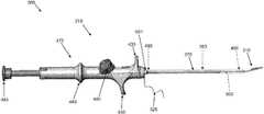
- FIG. 1is a side view of an embodiment of a system for all-inside suture fixation for implant attachment and soft tissue repair of the present invention
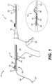
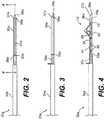
- FIG. 2is a top view of an embodiment of a needle of the system of FIG. 1 ;
- FIG. 3is a side view of the needle of FIG. 2 ;
- FIG. 4is a cross-sectional view taken along line 4 - 4 in FIG. 2 ;
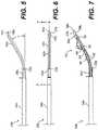
- FIG. 5is a side view of another embodiment of the needle for the system of FIG. 1 ;
- FIG. 6is a top view of the needle of FIG. 5 ;
- FIG. 7is a cross-sectional view taken along line 7 - 7 in FIG. 6 ;
- FIG. 8is a side view of a pusher of the system of FIG. 1 ;
- FIG. 9is a top view of an anchor of a suture of the system of FIG. 1 ;
- FIG. 10is an end view of the anchor of FIG. 9 ;
- FIG. 11is a side view of the anchor of FIG. 9 ;
- FIG. 12is a top view of another embodiment of an anchor of the suture for the system of FIG. 1 ;
- FIG. 13is an end view of the anchor of FIG. 12 ;
- FIG. 14is a side view of the anchor of FIG. 12 ;
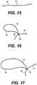
- FIG. 15is a view of an anchor threaded onto a suture of the system of FIG. 1 ;
- FIG. 16is a view of the anchor and suture of FIG. 15 with a loop and a self-locking slide knot formed in the suture;
- FIG. 17is a view of the anchor and suture of FIG. 16 with a second anchor positioned on the suture;
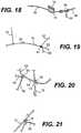
- FIG. 18is a partial view of the second anchor and suture of FIG. 17 ;
- FIG. 19is a partial view of the second anchor and suture of FIG. 17 with a needle threaded on the suture;
- FIG. 20is a partial view of the needle threaded on the suture and passing through the center of the suture at the second anchor;
- FIG. 21is a partial view of the needle passing through the center of the suture at the second anchor a second time
- FIG. 22is a view of the anchor with a knot securing it to the suture
- FIG. 23is a partial view of the suture and the second anchor at one end thereof;
- FIG. 24is a perspective view of a meniscus with an implant positioned on the meniscus
- FIG. 25is a view of the implant after it has been secured to the remaining surrounding soft tissue, such as meniscus;
- FIG. 26is a view of the suture and anchor configuration of the system of FIG. 1 ;
- FIG. 27is a top view of the needle with the pusher extended therefrom;
- FIG. 28is a side view of the suture being threaded into the pusher and the needle
- FIG. 29is a side view of the suture further being threaded into the pusher and the needle;
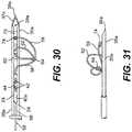
- FIG. 30is a top view of the needle with the suture loaded therein;
- FIG. 31is a side view of the needle of FIG. 30 ;
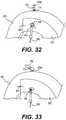
- FIG. 32is a top view of the needle of the system of FIG. 1 piercing the implant and meniscus of FIG. 25 at a first location;
- FIG. 33is a top view of the needle of FIG. 32 after the first anchor has been deployed from the needle with the pusher;
- FIG. 34is a perspective view of the needle of FIG. 32 after it has been pulled back through the meniscus and implant;
- FIG. 35is a top view of the needle of FIG. 32 piercing the implant and remaining surrounding soft tissue, such as meniscus, of FIG. 25 at a second location;
- FIG. 36is a top view of the needle of FIG. 35 after the second anchor has been deployed from the needle with the pusher;
- FIG. 37is a top view of the needle of FIG. 35 after is has been pulled back through the meniscus and implant;
- FIG. 38is a top view of the needle of FIG. 37 with the pusher extended out of the needle;
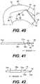
- FIG. 39is a top view of the needle of FIG. 38 with the pusher pushing the knot against the implant;
- FIG. 40is a top view of the needle of FIG. 39 after it has been pulled back following knot pushing and suture tensioning;
- FIG. 41is a side view of the needle of FIG. 40 with the suture exposed to the needle cutting surface;
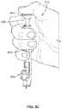
- FIG. 42is a side view of another embodiment of the needle of FIG. 40 with the suture exposed to a cutting surface on a cutting sheath;
- FIG. 43is a top view of the repaired meniscus with the suture tightly in place
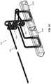
- FIG. 44is a side view of another embodiment of a system for all-inside suture fixation for implant attachment and soft tissue repair of the present invention.
- FIG. 45is a proximal end view of a body portion of the system of FIG. 44 ;
- FIG. 46is a side view of an embodiment of a pusher of the system of FIG. 44 ;
- FIG. 47is a cross-sectional view of the pusher taken along line 47 - 47 in FIG. 46 ;
- FIG. 48Ais a side view of a proximal end of the pusher of FIG. 46 in a first position relative to the body portion;
- FIG. 48Bis the proximal end view of the body portion with a portion of the pusher in the first position of FIG. 48A ;
- FIG. 48Cis a side view of a needle of the system of FIG. 44 and a distal end of the pusher, with the pusher in the first position of FIG. 48A ;
- FIG. 49Ais a side view of the proximal end of the pusher of FIG. 46 in a second position relative to the body portion;
- FIG. 49Bis the proximal end view of the body portion with a portion of the pusher in the second position of FIG. 49A ;
- FIG. 49Cis a side view of the needle and the distal end of the pusher, with the pusher in the second position of FIG. 49A ;
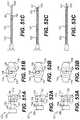
- FIG. 50Ais a side view of the proximal end of the pusher of FIG. 46 in a third position relative to the body portion;
- FIG. 50Bis the proximal end view of the body portion with a portion of the pusher in the third position of FIG. 50A ;
- FIG. 50Cis a side view of the needle and the distal end of the pusher, with the pusher in the third position of FIG. 50A ;
- FIG. 51Ais a side view of the proximal end of the pusher of FIG. 46 in a fourth position relative to the body portion;
- FIG. 51Bis the proximal end view of the body portion with a portion of the pusher in the fourth position of FIG. 51A ;
- FIG. 51Cis a side view of the needle and the distal end of the pusher, with the pusher in the fourth position of FIG. 51A ;
- FIG. 52Ais a side view of the proximal end of the pusher of FIG. 46 in a fifth position relative to the body portion;
- FIG. 52Bis the proximal end view of the body portion with a portion of the pusher in the fifth position of FIG. 52A ;
- FIG. 52Cis a side view of the needle and the distal end of the pusher, with the pusher in the fifth position of FIG. 52A ;
- FIG. 53Ais a side view of the proximal end of the pusher of FIG. 46 in a sixth position relative to the body portion;
- FIG. 53Bis the proximal end view of the body portion with a portion of the pusher in the sixth position of FIG. 53A ;
- FIG. 53Cis a side view of the needle and the distal end of the pusher, with the pusher in the sixth position of FIG. 53A ;
- FIGS. 54 and 55are schematic views showing an embodiment of a system formed in accordance with the present invention, wherein the system includes an anchor assembly and an inserter.
- FIG. 56is another illustration of the embodiment of FIGS. 54 and 55 where the housing of the inserter is transparent for ease of illustration.
- FIGS. 57-59illustrate a schematic of the distal portion of the inserter and the anchor assembly and further wherein portions of the anchor assembly (i.e., the terminus knot and the slip knot) are shown in schematic form for clarity of illustration;
- FIGS. 60-70Aare schematic views showing further details of the anchor assembly of the system of FIGS. 54-59 , wherein the terminus knot and the slip knot are shown in schematic form in FIG. 60 for clarity of illustration, and further wherein certain variations of the terminus knot and the slip knot are shown in line drawings in FIGS. 61, 68-70 and 68A-70A ;
- FIGS. 71-75are schematic views showing further details of the inserter of the system of FIGS. 54-59 , specifically the proximal portions of the inserter;
- FIGS. 76-82illustrate exemplary uses of the system of FIGS. 54-59 .
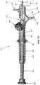
- FIG. 1A system 1 for repairing soft tissue, such as for example a meniscus, according to an embodiment of the present invention is illustrated in FIG. 1 .
- the system 1includes an applicator 10 that is constructed and arranged to deploy a suture 12 to soft tissue, such as the meniscus.
- the suture 12generally includes a flexible length of suture material 58 and includes a pair of anchors 60 , 70 positioned thereon. The suture 12 will be discussed in greater detail below.
- the applicator 10includes a body portion 14 that defines a handle 16 that is configured to be grasped by the user.
- the body portion 14 of the applicator 10receives a cannula 18 that extends from the body portion 14 in a direction that is away from the handle 16 .
- the body portion 14 and cannula 18may be constructed and arranged like those described and shown in U.S. Pat. No. 5,928,252, which is incorporated herein by reference in its entirety. Because the inner workings of the body portion 14 are not related to the present invention, they are not described in detail herein.
- the applicator 10also includes a needle 20 that is connected to a distal end of the cannula 18 .
- the needle 20may be considered to be a part of the cannula 18 itself.
- the needle 20will be described in greater detail below.
- the applicator 10also includes a pusher 23 that includes a hollow rod 24 that extends through the body portion 14 , the cannula 18 , and is slidingly received by the needle 20 .
- a knob 26is attached to one end of the rod 24 and a spacer 28 with a tab 29 is disposed between the knob 26 and a proximal end 15 of the body portion 14 so that the movement of the knob 26 relative to the body portion 14 and, hence, movement of the rod 24 relative to the needle 20 , may be limited to prevent premature deployment of one of the anchors 60 prior to the placement of the other anchor 70 , as described in further detail below.
- a trigger 30is connected to and extends from the body portion 14 , as shown in FIG. 1 . The trigger 30 is configured to manually control the advancement of the rod 24 within the cannula 18 .
- a side lever 32is connected to the body portion so as to be pivotable thereon. Operation of the side lever 32 will be discussed in greater detail below.
- a depth penetration limiter 21is placed over the distal end of the cannula 18 so as to partially cover the needle 20 .
- the limiter 21provides the user with a visualization of the depth of the needle 20 in the tissue to avoid neurovascular injury.
- An outer sheath 22is placed over the limiter 21 to aid in the insertion of the cannula 18 into the incision already created in the patient.
- the outer sheath 22may be designed to partially surround the limiter 21 so that the user may still see at least a portion of the limiter 21 when the needle 20 is being inserted into the incision.
- the outer sheath 22is removed by the user once the cannula 18 has been inserted into the incision site.
- the needle 20 aincludes a sleeve 34 a that is attached to the cannula 18 at a proximal end.
- the needle 20 aalso includes a distal end 36 a that is connected to the sleeve 34 a and is constructed and arranged to be inserted into a meniscus or a tissue.
- the distal end 36 ais substantially straight and includes a point 38 a for piercing the meniscus or tissue and a slot 40 a , which allows for the flexible length 58 of the suture 12 to extend out of the needle 20 a .
- the distal end 36 a of the needle 20 aalso includes a cutting surface 37 a that is constructed and arranged to cut excess suture 12 , which will be described in greater detail below.
- a cutting sheath 35 athat at least partially surrounds the distal end 36 a may also be provided.
- the cutting sheath 35 acompletely surrounds the circumference of the distal end 36 a .
- the cutting sheath 35 amay only partially surround the distal end 36 a .
- the cutting sheath 35 ais configured to be slidable relative to the distal end 36 a so that it may be moved longitudinally along the distal end 36 a toward the point 38 a , and then moved back again toward the sleeve 34 a .
- the cutting sheath 35 amay include a tab that extends outward from the needle 20 a so that the user may manipulate the cutting sheath 35 a via the tab. As shown, the cutting sheath 35 a includes at least one cutting surface 33 a that is constructed and arranged to cut excess suture 12 , which will be described in greater detail below.
- the distal end 36 ais configured to hold the pair of anchors 60 , 70 of the suture 12 .
- the needle 20 amay include a dimple 39 a located near the point 38 a to assist in seating the anchors 60 , 70 prior to deployment of the anchors 60 , 70 from the needle 20 a , as will be described in greater detail below.
- the needle 20 amay be manufactured from, for example stainless steel, and is sized to withstand insertion through the implant and the meniscus substantially without bending or budding.
- FIGS. 5-7Another embodiment of a needle 20 b that may be used as the needle 20 in the applicator 10 is shown in FIGS. 5-7 .
- the needle 20 bincludes a sleeve 34 b that is attached to the cannula 18 at a proximal end.
- the needle 20 balso includes a distal end 36 b that is connected to the sleeve 34 b and is constructed and arranged to be inserted into a meniscus or a tissue.
- the distal end 36 bis curved such that it extends at an angle ⁇ relative to the sleeve 34 b .
- the angle ⁇may be about 15-45 degrees, and for example, about 30 degrees.
- the distal end 36 balso includes a point 38 b for piercing the meniscus or tissue and a slot 40 b , which allows for portions of the suture 12 to extend out of the needle 20 b .
- the distal end 36 b of the needle 20 balso includes at least one cutting surface 37 b that is constructed and arranged to cut excess suture 12 .
- a cutting sheath 35 b that at least partially surrounds the distal end 36 bmay also be provided.
- the cutting sheath 35 bcompletely surrounds the circumference of the distal end 36 b .
- the cutting sheath 35 bmay only partially surrounds the distal end 36 b .
- the cutting sheath 35 bis configured to be slidable relative to the distal end 36 b so that it may be moved longitudinally along the distal end 36 b toward the point 38 b , and back again to the sleeve 34 b .
- the cutting sheath 35 bmay include a tab that extends outward from the needle 20 b so that the user may manipulate the cutting sheath 35 b via the tab. As shown, the cutting sheath 35 b includes a cutting surface 33 b that is constructed and arranged to cut excess suture 12 .
- the distal end 36 bis also configured to hold the pair of anchors 60 , 70 .
- the needle 20 bmay also include a dimple 39 b located near the point 38 b to assist in seating the anchors 60 , 70 prior to deployment.
- the needle 20 bmay be manufactured from, for example, stainless steel, and is sized to withstand insertion through the implant and the meniscus substantially without bending or buckling.
- the rod 24is hollow and is configured to receive the flexible length 58 of the suture 12 that extends away from the needle 20 .
- the knob 26includes a hole for receiving the rod 24 , so that the flexible length 58 of the suture 12 may extend through the knob 26 as well.
- a distal portion of the rod 24includes a pair of slots 42 that are configured to allow the flexible length 58 of the suture 12 to be threaded out of the rod 24 via one slot 42 (the distal slot) and back into the rod 24 via the other slot 42 (the proximal slot), as represented by an exposed portion 44 of the flexible length 58 of the suture 12 .
- the rod 24may be flexible so that it may be used with the embodiment of the needle 20 b described above.
- FIGS. 9-11illustrated an embodiment of an anchor 46 that may be used as the anchors 60 , 70 of the suture 12 .
- the anchor 46includes a tab 48 that extends upward from a body 50 .
- the body 50has opposing ends 51 that are substantially perpendicular to a longitudinal axis LA of the anchor 46 .
- a hole 52 that is centered on the longitudinal axis LAextends through the body 50 and the tab 48 where the body 50 and tab 48 are connected. Otherwise, the body 50 includes a hollowed out half-cylinder 53 at portions where the tab 48 is not connected.
- the anchor 46may be made out of any material desired such as, polymer, for example polyether ether ketone (PEEK), or a bioabsorbable polymer, for example poly(L-lactide).
- FIGS. 12-14Another embodiment of an anchor 54 for use in the suture 12 of the system 1 is shown in FIGS. 12-14 .
- the anchor 54is a solid rod with a pair of holes 56 that extend substantially perpendicularly through the longitudinal axis of the rod.
- the holes 56are sized to receive a flexible portion of the suture 12 .
- a recessed channel 57is located between the holes 56 to seat the flexible length 58 of the suture 12 .
- the anchor 54may be made out of any material desired such as, polymer, for example polyether ether ketone (PEEK), or a bioabsorbable polymer, for example poly(L-lactide).
- PEEKpolyether ether ketone
- a bioabsorbable polymerfor example poly(L-lactide
- the anchormay include at least one barb that is formed from or connected to a main body portion of the anchor.
- the barbmay be constructed and arranged to be biased to an orientation in which a free end of the barb extends away from the body, yet is oriented such that the free end is near the body when suitable pressure is applied to the barb.
- FIGS. 15-23show the various stages of an embodiment of assembling the suture 12 of the system 1 of FIG. 1 .
- FIG. 15shows the flexible length 58 of the suture 12 with one anchor 60 threaded thereon.
- FIG. 16shows a loop 62 and a knot 64 that closes the loop 62 , with the anchor 60 being located within the loop 62 .
- the knot 64may be a self-locking slide knot. Methods for tying a self-locking slide knot are described in, for example, “A New Clinch Knot,” Weston, P. V., Obstetrics & Gynecology, Vol. 78, pp. 144-47 (1991); “Physical Properties of Self Locking and Conventional Surgical Knots,” Israelsson, L.
- FIG. 17Note that the Figures are not necessarily drawn to scale. This distance is only meant to be an example and is not intended to be limiting in any way.
- the flexible length 58 of the suture 12is tied off with one hitch knot 74 on the anchor 70 , as shown in FIG. 18 .
- a needle 72is threaded with the remainder of the flexible length 58 .
- the end of the flexible length 58 with the needle 72is passed through the center of the suture of the hitch knot twice to hold the hitch knot 74 in place, as shown in FIGS. 20 and 21 .
- the excess flexible length 58is cut, leaving approximately 2 mm as a tail.
- the tip of the flexible length 58may be melted to prevent fraying of the suture 12 .
- An assembled suture 12 before it is loaded into the applicator 10is shown in FIG. 26 .
- FIG. 24shows a damaged meniscus 80 having a rim 81 , and an implant 82 positioned adjacent the damaged part of the meniscus 80 .
- the implant 82may be any type of implant 82 suitable for such meniscus repair.
- the implant 82includes collagen.
- the implant 82includes the CMI, a collagen-based meniscus implant.
- the implant 82 illustrated in the Figureshas already been cut to the appropriate size. Both ends of the implant 82 may be temporarily stapled or sutured using conventional means to hold the implant 82 in place while it is being secured to the meniscus 80 .
- FIG. 25shows a pair of staples 84 , or sutures, holding the implant 82 in place.
- the cannula 18is inserted into the body portion 14 of the applicator 10 .
- the needle 20 a of FIGS. 2-4is shown.
- the needle 20 bmay also be used in the same way.
- the illustrated and described embodimentsare not intended to be limiting in any way. While holding down the side lever 32 with a finger or a thumb, the rod 24 of the pusher 23 is inserted by the user into the proximal end 15 of the body portion 14 until the end of the rod 24 extends past the point 38 a of the needle 20 a with the slots 42 facing upward, as shown in FIG. 27 .
- an end 59 of the suture 12 that is opposite the anchor 70is threaded though the rod 24 of the pusher 23 at the distal end 36 a of the needle 20 a .
- the end 59 of the suture 12is laced through the distal end of the rod 24 , pulled out of the rod 24 at the distal slot 42 , threaded back into the rod 24 at the proximal slot 42 , thereby leaving the exposed portion 44 outside of the rod 24 .
- the end 59 of the suture 12may extend several inches outside the pusher 23 beyond the proximal end 15 of the body portion 14 of the applicator 10 so that the user may grasp the suture 12 during the implant attachment procedure, which will be described below.
- the userthen presses the side lever 32 and retracts the pusher 23 back into the needle 20 a , as shown in FIG. 29 , to locate the slots 42 and the exposed portion 44 of the suture 12 before the proximal end of the needle slot 40 a , as shown in FIG. 30 .
- the anchor 60is inserted into the distal end 36 a of the needle 20 a , and is followed by the anchor 70 , as shown in FIGS. 30 and 31 .
- the end 59 of the flexible length 58 that extends out of the pusher 23 at the proximal end 15 of the body portion 14 of the applicator 10may be pulled so that the knot 64 is generally located on a side of the anchor 60 that is opposite the other anchor 70 , as shown in FIG. 31
- a portion of the flexible length 58may extend outside of the cannula 18 via the slot 40 a of the needle 20 a , as shown in FIGS. 30 and 31 .
- the pulling of the trigger 30causes the anchor 70 , the anchor 60 , and the knot 64 to be deployed in that order.
- the userplaces the spacer 28 between the knob 26 and the proximal end 15 of the body portion 14 so that the advancement of the anchor 60 will be limited until the placement of the anchor 70 is complete.
- the userthen inserts the depth penetration limiter 21 and the outer sheath 22 over the distal end of the cannula 18 so as to cover the needle 20 during insertion of the needle 20 into the incision site.
- the outer sheath 22may be removed from the cannula 18 .
- the spacer 28 , the outer sheath 22 , and the depth penetration limiter 21should be considered optional.
- the illustrated embodimentis not intended to be limiting in any way.
- the usermay then advance the anchors 60 , 70 until the anchor 70 is located near the point 38 a of the needle 20 a , without extending out of the needle 20 a .
- the dimple 39 amay be used to assist with the placement of the anchor 70 .
- the usershould feel a slight resistance to the advancement of the anchor 70 , which signals the user to stop advancing the pusher 23 .
- the use of the dimple 39 ashould be considered to be optional.
- the illustrated embodimentis not intended to be limiting in any way.
- the userWhile griping the handle 16 and the trigger 30 on the applicator 10 , the user inserts the needle 20 a into a patient at an incision site so that the needle 20 a may then be inserted through the implant 82 and through the meniscus 80 at a first location 86 , for example near the center of the implant 82 , to a side opposite the insertion site, as shown in FIG. 32 .
- the usershould be sure that the hitch knot 74 on the anchor 70 has passed through the meniscus 80 , as shown in FIG. 32 .
- the userthen advances the pusher 23 via the trigger 30 until the anchor 70 is pushed outside the needle 20 a , as shown in FIG. 33 .
- the usershould be careful to not advance the pusher 23 further to avoid the premature deployment of the anchor 60 .
- the use of the spacer 28assists in preventing the premature deployment of the anchor 60 .
- the dimple 39 a that is located near the point 38 a of the needle 20 amay also be used to provide the user with tactile feedback that the anchor 60 has been advanced to its proper pre-deployment position.
- the userthen retracts the needle 20 a slowly from the meniscus 80 and the implant 82 , leaving the anchor 70 behind on the opposite side of the meniscus 80 .
- the anchor 60will remain inside the needle 20 a . If the user hasn't already done so, the user next advances the anchor 60 until the anchor 60 is located near the point 38 a of the needle 20 a .
- the dimple 39 amay be used to guide the user to correctly position the anchor 60 .
- the userWhile gripping the handle 16 and the trigger 30 on the applicator 10 , the user inserts the needle 20 a though the implant 82 and through the meniscus 80 at a second location 88 , which may be for example near the first location 86 , until the center of the anchor 60 is outside the opposite side of the meniscus 80 , as shown in FIG. 35 . If the user hasn't already done so, the user next removes the spacer 28 from the rod 24 by grasping the tab 29 and pulling the spacer 28 away from the rod 24 . The user then advances the pusher 23 until the anchor 60 is pushed outside the needle 20 a , as shown in FIG. 36 . The user then retracts the needle 20 a , thereby leaving the anchor 60 on the opposite side of the meniscus 80 , as shown in FIG. 37 .
- the usermay then advance the pusher 23 via the trigger 30 so that the rod 24 extends approximately 1 cm beyond the point 38 a of the needle 20 a , as shown in FIG. 38 . While gripping the handle 16 and the trigger 30 of the applicator 10 , the user then holds the tip of the rod 24 against the knot 64 and pushes the knot 64 to the surface of the implant 82 , being careful not to push the knot 64 through the implant 82 .
- the usercontinues to grip the handle 16 and the trigger 30 while gently pulling on the end 59 of the flexible length 58 of the suture 12 at the proximal end 15 of the body portion 14 of the applicator 10 until slack in the suture 12 is taken up, and the anchors 60 , 70 sit flat against the meniscus 80 , as shown in FIGS. 39 and 40 .
- the usermay extend the rod 24 of the pusher 23 out of the needle 20 a approximately 1 cm.
- the usermay then rotate the pusher 23 up to approximately 180 degrees, or until the slots 42 and the exposed portion 44 of the suture 12 are positioned to come into contact with the cutting surface 37 a when the pusher 23 is pulled back toward the proximal end 15 of the body portion 14 of the applicator 10 , as shown in FIG. 41 .
- the usermay shear the exposed portion 44 of the suture 12 against the cutting surface 37 a by sliding the pusher 23 longitudinally against the cutting surface 37 a , as shown in FIG. 41 , thereby leaving a short tail 67 near the knot 64 , as shown in FIG. 43 .
- the pusher 23may have to be moved back and forth against the cutting surface 37 a before the suture 12 is fully cut.
- the usermay shear the exposed portion 44 of the suture 12 against the cutting surface 33 a by sliding the cutting sheath 35 a along the distal end 36 a and toward the point 38 a of the needle 20 a , as shown in FIG. 42 , thereby leaving a short tail 67 near the knot 64 , as shown in FIG. 43 .
- the cutting sheath 35 amay have to be moved back and forth along the distal end of the needle 20 a before the suture 12 is fully cut.
- the aforementioned system 1 and methodprovide an all-inside suture fixation to the implant and meniscus, because the needle 20 a of the applicator 10 has not been removed from the patient's body between the deployment of the anchor 70 , the pushing of the knot 64 , and the cutting of the excess flexible length 58 of the suture 12 .
- Thismay be beneficial to the patient because it may reduce the time the applicator 10 is in the patient's body, and allows for a single, small entry point of the needle 20 a , at the incision, into the patient's body.
- the usermay then repeat the steps shown in FIGS. 32-43 for any remaining sutures 12 that are needed to complete the fixation of the implant 82 to the meniscus 80 .
- itmay take three or more sutures 12 to secure the implant 82 .
- the usermay remove the body portion 14 of the applicator 10 and pusher 23 from the cannula 18 , and trim the excess flexible length 58 of the suture 12 with scissors, or some other cutting device.
- the illustrated embodimentsare not intended to be limiting in any way.
- one or both of the anchors 60 , 70may be the anchor described above that includes one or more barbs. This allows the user to advance the pusher 23 via the trigger 30 only until a distal end of the anchor is located adjacent the point of the needle 20 in an orientation in which the barb is no longer engaged by the wall of the needle 20 . When the anchor is in this position, the wall of the needle 20 is no longer exerting pressure on the barb, thereby allowing the barb to be biased outward and away from the body of the anchor. The barb may then be used to engage the anchor with the meniscus 80 so that when the user pulls the needle 20 back through the meniscus 80 and the implant 82 , the entirety of the anchor will pull out of the needle 20 without further advancement of the pusher 23 .
- the needle 20may be designed such that the tab 48 on the anchor 46 may be used to engage the anchor 46 with the meniscus 80 before the anchor 46 exits the needle 20 . This allows the entirety of the anchor 46 to be pulled out of the needle 20 when the needle 20 is pulled back through the meniscus 80 , rather than pushing the entirety of the anchor 46 out of the needle 20 with the pusher 23 , as described in the embodiments above.
- the needle 20may be inserted through the meniscus 80 a first location near the tear.
- the first anchor 70 of the suture 12may then be delivered to an opposite side of the meniscus 80 , and the needle 20 retracted from the meniscus 80 , without pulling out of the body.
- the needlemay then be inserted through the meniscus 80 at a second location on an opposite side of the tear as the first location.
- the second anchor 60 of the suture 12may then be delivered to the opposite side of the meniscus 80 . Once the second anchor 60 is in the proper position, the user may then push the knot 64 to a surface of the meniscus 80 to tighten the suture. The excess of the flexible length 58 of the suture 12 may then be cut with any of the cutting methods described above.
- a system 100 for repairing a meniscusincludes an applicator 110 that is constructed and arranged to deploy the suture 12 , which includes the flexible length 58 and the two anchors 60 , 70 , as described above, to the meniscus.
- the applicator 110includes a body portion 114 that is configured to be grasped by the user.
- the body portion 114includes a pair of extensions 116 at a proximal end 115 of the body portion 114 .
- Each of the extensions 116is constructed and arranged to engage a finger of the user such that the body portion 114 is may be held in between the fingers in a similar way that a syringe is typically held.
- the body portion 114 of the applicator 110receives a cannula 118 that extends from a distal end 113 of the body portion 114 in a direction that is away from the proximal end 115 .
- the cannula 118may be constructed and arranged like the cannula 18 described and illustrated above, and in U.S. Pat. No. 5,928,252, which is hereby incorporated by reference in its entirety, and may be connected to the body portion 114 in a similar manner.
- the applicator 110also includes a needle 120 that has a cutting surface 121 at a distal end thereof.
- the needle 120is connected to a distal end of the cannula 118 so that it is operatively connected to the distal end 113 of the body portion 114 .
- the needle 120may be considered to be a part of the cannula 118 itself.
- the needle 120may be of the same design as the needle 20 a discussed above. As such, details of the needle 120 will not will be described in further detail. Instead, reference should be made to the needle previously described and illustrated.
- the applicator 110also includes a pusher 123 .
- the pusher 123includes a rod 124 (shown in FIG. 46 ) that extends through a central lumen 112 of the body portion 114 , a central bore (not shown) of the cannula 118 , and is slidingly received by the needle 120 .
- a knob 126is attached to one end of the rod 124 and is configured to be grasped by the user so that the user may manipulate the rod 124 , as described in further detail below.
- the rod 124includes proximal end 125 and a distal end 127 , which has a smaller diameter than the diameter of proximal end 125 , as illustrated.
- the distal end 127is configured to include a pair of slots 142 that are similar to the slots 42 discussed above.
- a central bore 122extends through the rod 124 and the knob 126 so that the flexible length 58 of the suture 12 may be threaded through the slots 142 , through the rod 124 , and through the knob 126 , as shown in FIG. 46 .
- the pusher 123includes a first projection 128 that projects from the rod 124 and defines a first stop surface 129 on one side thereof.
- the first projection 128may be configured as a square or rectangular tab, or may be in the shape of a cylinder.
- the illustrated embodimentis not intended to be limiting in any way.
- the knob 126 of the pusher 123includes a stopper portion 130 that is connected to the rod 124 and defines a second stop surface 131 .
- the pusher 123also includes a second projection 132 that projects from the rod 124 and defines a third stop surface 133 on one side thereof.
- the second projection 130is axially spaced from the first projection 128 and is axially located between the first projection 128 and the distal end 127 of the rod 124 .
- the second projection 130is also radially spaced from the first projection 128 .
- the radially spacingis defined by angle ⁇ , and in the illustrated embodiment, the angle ⁇ is about 90 degrees. It is contemplated that the angle ⁇ may be in the range of about 10 degrees to about 370 degrees, as will be appreciated in the discussion below.
- the illustrated embodimentis not intended to be limiting in any way.
- the body portion 114defines an outer surface 134 at its proximal end that is configured to engage the stop surfaces 129 , 131 , 133 described above as the pusher 123 is moved to different positions relative to the body portion 114 and needle 120 .
- the body portion 114also includes an opening 136 , shown in the Figures to be shaped as a keyhole, that is axially connected to the central lumen 112 and is constructed and arranged to receive the first projection 128 and the second projection 130 of the pusher 123 , as discussed in further detail below.
- the arrangement of the opening 136 in the proximal end 115 of the body portion 114is such that the pusher 123 should be in the proper orientation relative to the body portion 114 in order for the pusher 123 to move toward the needle 120 in an axial direction.
- the respective projection 128 , 130is then located within the central lumen 112 of the body portion 114 .
- the central lumen 112is sized to allow the projections 128 , 130 to rotate with the rod 124 about a central axis. However, when one of the projections 128 , 130 is positioned within the opening 136 , the rod 124 will be prevented from rotating.
- FIGS. 48A-53Cillustrate portions of the system 100 during different stages of repairing a meniscus or other soft tissue.
- the pusher 123is disposed in a first orientation and first axial position relative to the body portion 114 and the needle 120 .
- the third stop surface 133is engaged with the outer surface 134 of the body portion 114 such that pressure applied to the knob 126 toward the body portion 114 will not cause the pusher 123 to move in an axial direction.
- Thisallows the first anchor 70 to stay within the needle 120 , as shown in FIG. 48C , even if pressure is applied to the pusher 123 via the knob 126 .
- Thismay allow the user to apply pressure to the applicator 110 via the knob 126 as the needle 120 is initially inserted through the implant 82 and meniscus 80 , as described above.
- the usermay hold the body portion 114 and engage the extensions 116 with two fingers, while applying pressure to the knob 126 with a thumb, like a syringe.
- the usermay rotate the pusher 123 , via the knob 126 , to a second orientation, which is 90 degrees from the first orientation, as shown in FIGS. 49A-C .
- This orientationaligns the second projection 132 of the pusher 123 with the opening 136 of the body portion 114 , as shown in FIG. 49B . Because the pusher 123 has not yet been moved axially, the first anchor 70 is still located in the needle 120 , as shown in FIG. 49C .
- the usermay then apply pressure to the pusher 123 in an axial direction via the knob 126 until the first surface 129 of the first projection 128 engages the outer surface 134 of the body portion 114 , as shown in FIG. 50A .
- the second projection 132has passed all the way through the opening 136 of the body portion 114 such that is in the central lumen 112 .
- the first anchor 70has been discharged by the pusher 123 out of the needle 120 .
- Other aspects of the discharge of the anchor 70are discussed above and shown in FIG. 33 .
- the usermay then pull the needle 120 in a similar manner so that it clears the meniscus 80 and the implant 82 , and then insert the needle through the implant 82 and the meniscus 80 at a second location.
- the usermay then rotate the pusher 123 to a third orientation, as shown in FIGS. 51A-C , which is 90 degrees from the second orientation, and 180 degrees from the first orientation.
- the first protrusion 128is aligned with the opening 136 , and the second anchor 60 is still located within the needle 120 .
- the usermay then apply pressure to the pusher 123 via the knob 123 until the second stop surface 131 of the stopper 130 engages the outer surface 134 of the body portion 114 , as shown in FIGS. 52A-B .
- the first projection 128has passed all of the way through the opening 136 and is in the central lumen 112 of the body portion 114 .
- the second anchor 60has been discharged from the needle 120 by the pusher 123 .
- Other aspects of the discharge of the second anchor 60are discussed above and shown in FIG. 36 . As discussed above and shown in FIGS.
- the knot 64 of the suture 12may then be pushed against the implant 82 , although in this embodiment, the distal end 127 of the rod 124 of the pusher 123 is used to push the knot 64 rather than the rod 24 shown in FIGS. 37-40 .
- the pusher 123may be rotated out of the third orientation, as shown in FIGS. 52A-C so as to shear the flexible length 58 of the suture 12 against the cutting surface 121 of the needle 120 .
- the applicator 110may be pulled out of the body. The applicator 110 may then be disposed of, or, if desired, may be cleaned, sterilized, and used again.
- a system 305which generally comprises an anchor assembly 310 for use in securing together two or more objects within the body of a patient (e.g., as in re-approximating soft tissue portions or securing an implant to soft tissue), and an inserter 315 for deploying anchor assembly 310 within the body of a patient.
- an anchor assembly 310for use in securing together two or more objects within the body of a patient (e.g., as in re-approximating soft tissue portions or securing an implant to soft tissue), and an inserter 315 for deploying anchor assembly 310 within the body of a patient.
- portions of anchor assembly 310i.e., the terminus knot and the slip knot, which will be hereinafter discussed
- Anchor assembly 310is shown in further detail in FIGS. 60 and 61 .
- Anchor assembly 310generally comprises a pair of anchors 320 (i.e., a distal anchor 320 A and a proximal anchor 320 B) and a suture 325 for adjustably connecting together the pair of anchors 320 (i.e., distal anchor 320 A and proximal anchor 320 B).
- portions of anchor assembly 310i.e., the terminus knot and the slip knot, which will be hereinafter discussed
- FIG. 61the terminus knot and the slip knot (which will be hereinafter discussed) are shown in one exemplary embodiment.
- anchors 320i.e., distal anchor 320 A and proximal anchor 320 B
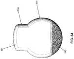
- anchors 320comprise generally cylindrical bodies 330 having upraised portions 335 .
- the distal ends of anchors 320comprise a rounded leading edge 337 , and generally cylindrical bodies 330 may be beveled or chamfered at 340 .
- the proximal ends of anchors 320comprise a rounded trailing edge 342 , and generally cylindrical bodies 330 may be beveled or chamfered at 345 .
- Rounded edges 337 , 342help facilitate smooth passage of anchors 320 along the shaft of inserter 315 and through soft tissue, and minimize trauma to the tissue, as will hereinafter be discussed.
- Bevels 340 , 345may facilitate passage of anchors 320 along the shaft 370 of inserter 315 , as will hereinafter be discussed.
- a pair of bores 350extend through generally cylindrical bodies 330 and upraised portions 335 of anchors 320 .
- Bores 350are sized to slidably receive suture 325 therethrough, as will hereinafter be discussed.
- a slot 355connects the lower ends of bores 350 (i.e., distal bore 350 A and proximal bore 350 B) to one another. Slot 355 is sized so that when suture 325 is received in slot 355 , suture 325 does not extend beyond the outer perimeter of generally cylindrical bodies 330 .
- suture 325is attached to anchors 320 by passing suture 325 down distal bore 350 A of distal anchor 320 A, proximally along slot 355 in distal anchor 320 A, up proximal bore 350 B of distal anchor 320 A, down distal bore 350 A of proximal anchor 320 B, proximally along slot 355 in proximal anchor 320 B, up proximal bore 350 of proximal anchor 320 B and then proximally along inserter 315 .
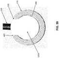
- anchors 320have increased material adjacent to the suture so as to provide greater strength to the construct. Further, such a suture routing also separates the suture from the edges of slot 405 , as illustrated in FIG. 59 , which may minimize the risk of abrasion of the suture 325 by contact on the edges of slot 405 .
- the upraised portion 335is not so tall as to extend beyond slot 405 , and thus the shape of anchor 320 provides for high strength while still maintaining a low profile to minimize trauma to the soft tissue and/or implant during implantation.
- the distal end of suture 325is secured to distal anchor 320 A. More particularly, and looking now at FIGS. 61 and 68-70 , in one embodiment of the present invention, the distal end of suture 325 comprises a terminus knot 360 which is formed in the length of suture entering distal bore 350 A of distal anchor 320 A and the length of suture exiting proximal bore 350 B of distal anchor 320 A. Forming terminus knot 360 in this manner may provide a secure knot in the suture while also maintaining a low profile, particularly while the anchors are positioned within shaft 370 . Such a low profile knot may provide improved tactile feedback for the surgeon during implantation as less force will be required to pass the knot through the tissue and/or implant.
- terminus knot 360may be replaced/omitted by braiding, fusing or gluing the distal end of suture 325 to distal anchor 320 A so as to secure the distal end of suture 325 to distal anchor 320 A, and/or by forming the suture integral with distal anchor 320 A.
- a slip knot 365is formed in suture 325 in the length of suture entering distal bore 350 A of proximal anchor 320 B and the length of suture exiting proximal bore 350 B of proximal anchor 320 B.
- Slip knot 365is formed such that when anchors 320 A, 320 B have been appropriately deployed in the body of a patient, pulling on the proximal end of suture 325 locks the slip knot, whereby to set the expanse of suture extending between distal anchor 320 A and proximal anchor 320 B (and hence secure together two or more objects within the body of a patient, for example, re-approximating two portions of tissue or securing an implant to remaining tissue).
- slip knot 365may be a so-called one twist half hitch (OTHH) knot. Forming slip knot 365 in this manner may provide a secure knot in the suture. It should also be appreciated that “mirror” images of the terminus knot 360 , and/or the slip knot 365 , and/or combinations thereof may also be used.
- FIGS. 68A-70AOne such alternative slip knot is illustrated in FIGS. 68A-70A , where slip knot 365 ′ is a mirror image of slip knot 365 (though all other features described as to FIGS. 68-70 apply equally to the same features illustrated in FIGS. 68A-70A ).
- anchor assembly 310comprises a distal anchor 320 A, a proximal anchor 320 B, and a suture 325 which connects together distal anchor 320 A and proximal anchor 320 B, with a terminus knot being formed at distal anchor 320 A and a slip knot 365 (or 365 ′) being formed between the anchors 320 A, 320 B.
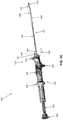
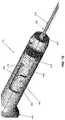
- inserter 315generally comprises a shaft 370 , a handle 375 and a pushrod assembly 380 (see FIGS. 56, 58, 69 and 72 ). Inserter 315 may also include a sheath 383 .
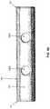
- shaft 370generally comprises a hollow tube having a distal end 385 ( FIG. 54 ), a proximal end 390 and a lumen 395 ( FIG. 58 ) extending therebetween. Distal end 385 of shaft 370 terminates in a sharp point 400 . A slot 405 ( FIG. 68 ) is formed in distal end 385 of shaft 370 and terminates in a proximal shoulder 410 .
- Shaft 370is sized to slidably receive anchors 320 therein. More particularly, and as seen in FIGS. 58, 59 and 69 , generally cylindrical bodies 330 of anchors 320 are slidably received within lumen 395 of shaft 370 , with upraised portions 335 of anchors 320 being slidably received in slot 405 of shaft 370 . Note that the disposition of upraised portions 335 of anchors 320 in slot 405 provides anchors 320 with a known disposition relative to shaft 370 and prevents anchors 320 from rotating relative to shaft 370 (and the remainder of inserter 315 ) when anchors 320 are disposed in shaft 370 . Note also that, as seen in FIG.
- upraised portions 335 of anchors 320do not extend radially beyond the perimeter of shaft 370 (i.e., the outermost portions of anchors 320 are contained within an axial projection of the cross-section of shaft 370 ), so that upraised portions 335 of anchors 320 do not engage tissue as shaft 370 of inserter 315 is advanced through tissue.
- a dimple 415FIG. 69 may be formed in lumen 395 just proximal to sharp point 400 .
- Dimple 415provides nominal resistance to the passage of anchors 320 along lumen 395 , such that anchors 320 cannot accidentally fall out of the distal end of shaft 370 and/or be accidentally forced out of the distal end of shaft 370 when inserter 315 is repositioned; at the same time, however, anchors 320 can be driven past dimple 415 and out of the distal end of shaft 370 with the force generated by pushrod assembly 380 , as will hereinafter be discussed. It should be appreciated that dimple 415 also provides audible and/or tactile feedback to the surgeon which indicates when an anchor 320 is driven past dimple 415 (and out the distal end of shaft 370 ).
- bevels 340 at the distal ends of anchors 320facilitate passage of anchors 320 past dimple 415 , and further may help to reduce potential trauma to the anchors themselves during passage past the dimple.
- Shaft 370may be straight or curved, as desired.
- handle 375comprises a body 420 ( FIG. 72 ) having a bore 425 , a first grip 430 , a second grip 435 and a third grip 440 .
- Body 405comprises a slot 445 ( FIG. 75 ) having a first portion 450 , a second portion 455 and a third portion 460 .
- a first shoulder 465is formed at the distal end of first portion 450 and separates first portion 450 from second portion 455
- a second shoulder 470is formed at the distal end of second portion 455 and separates second portion 455 from third portion 460 .
- the first shoulder 465may also include a proximal projection 466 such that, due to the bias of spring 484 , a button actuator 485 (and thus pusher 480 , both discussed below)) would be trapped against first shoulder 465 .
- a button actuator 485and thus pusher 480 , both discussed below
- Such a positionmay be suitable for transport and packaging of inserter 315 , as well as a beneficial pre-operative and starting position since the actuator and pusher can only be actuated by interaction of the surgeon or other user (e.g., by a proximal force on the actuator 485 or end cap 483 and proximal extension 482 , as discussed below).
- the second shoulder 470may include a proximal ramp 471 which, similar to the proximal projection 466 , may assist in seating the actuator 485 against the second shoulder 470 until the surgeon is ready to navigate to the third portion 460 .
- the ramp 471may be less severe of a shape as compared to projection 466 , however, since the force from the spring is less, if not nonexistent, and there is less of a need to protect against movement of the actuator 485 due to this position occurring during mid-surgery, rather than during packaging and shipping. Instead, ramp 471 may be useful to provide a tactile response to the surgeon as the surgeon navigates slot 445 and reaches the third portion 460 .
- Pushrod assembly 380generally comprises a cylinder 475 ( FIG. 72 ) which is sized to be slidably received in bore 425 of body 420 of handle 375 , a pusher 480 ( FIGS. 56, 58, 69 and 72 ) which is secured to the distal end of cylinder 475 and is sized to be slidably received in lumen 395 of shaft 370 , and an extension 482 ( FIG. 72 ) which is secured to the proximal end of cylinder 475 and is sized to extend proximally out of body 420 of handle 375 .
- Pusher 480may be formed of any material desired.
- pusher 480may be formed of superelastic Nitinol so that pusher 480 may both be naturally lubricious for ease of passing through shaft 370 and flex as it moves through a curved portion of shaft 370 .
- pusher 480may have a narrowed width at one or more portions along its length so as to further enhance flexibility.
- pusher 480may comprise a distal component 480 A ( FIG. 58 ) formed out of a relatively thin Nitinol rod and a proximal component 480 B formed out of a thicker Nitinol rod or a thicker, less flexible material (e.g., stainless steel).
- Pusher 480may be secured to cylinder 475 by securing pusher 480 to another member (e.g., a connector 481 , FIG. 72 ) which is itself secured to cylinder 475 .
- a connector 481e.g., FIG. 72
- Such a constructioncan be advantageous where the proximal end of pusher 480 is relatively thin (i.e., relative to cylinder 475 ) and made out of metal, and cylinder 475 is relatively wide (i.e., relative to the proximal end of pusher 480 ) and made out of plastic, since connector 481 can be of intermediate width (which makes it easier to secure to cylinder 475 ) and made out of metal, so that pusher 480 can be connected to connector 481 by crimping (e.g., by grinding a circumferential groove into the proximal end of pusher 480 , and then crimping connector 481 onto the circumferential groove in pusher 480 ).
- crimpinge.g
- the pusher 480may have a “D”-shaped cross-section (not shown), which provides a flat surface on one side. This shape may provide for even further improved action of the pusher within shaft 370 , particularly through any bend along the length of the shaft which could otherwise cause the pusher to crimp.
- the connection between pusher and connector 481may also thus be “D”-shaped, which may provide an improved connection between the elements and inhibit rotation of the pusher relative to cylinder 475 .
- Extension 482terminates in an end cap 483 .
- a spring 484is disposed within bore 425 of body 420 , as illustrated the spring may be positioned coaxially over extension 482 , and biases cylinder 475 , and hence pusher 480 , distally.
- a button actuator 485is secured to cylinder 475 of pushrod assembly 380 and extends through slot 445 in body 420 . If desired, button actuator 485 may be contoured (e.g., “cupped”) and/or textured so as to facilitate engagement by the finger of a user during use (e.g., such as when the user is wearing a wet glove, etc.). Button actuator 485 allows the user to move cylinder 475 within body 420 (and hence pusher 480 within shaft 370 ) as will hereinafter be discussed.
- the thumb (or another finger) of a usercan be used (in conjunction with spring 484 ) to step button actuator 485 through a series of motions within slot 445 in body 420 , whereby to step pusher 480 through a series of motions within shaft 370 so as to provide controlled deployment of anchors 320 from the distal end of shaft 370 .
- pusher 480will be stepped through a corresponding series of motions with shaft 370 so as to provide controlled deployment of anchors 320 from the distal end of shaft 370 , as will hereinafter be discussed.
- actuator 485extension 482 and end cap 483 may instead be engaged by a user's hand to step pusher 480 through the series of motions to provide controlled deployment of anchors 320 .
- spring 484may not have sufficient force to actually perform the deployment of anchors 320
- the springbiases actuator 485 , and thus pusher 480 , in a distal direction such that the spring force is in the same direction as the deployment actions of the user.
- the userdoes not need to apply additional force during deployment of the anchors 320 to overcome the spring force (except when moving the actuator 485 away from engagement with the first and second shoulders 465 , 470 ).
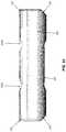
- sheath 383may be disposed over at least a portion of shaft 370 .
- Sheath 383comprises a distal end 490 ( FIG. 54 ), a proximal end 495 and a lumen 500 extending therebetween.
- the lumenhas a diameter sufficient for passage of shaft 370 therethrough, and in instances where, as illustrated, the shaft 370 includes a bend along its length, the lumen may have a diameter sufficient to allow passage of such a nonlinear shaft 370 therethrough.
- Sheath 383may also have a length that is somewhat shorter than the length of shaft 370 . Further, the sheath may be cut even shorter, if desired, by trimming a desired length of the distal portion of the sheath (see FIG.
- the usercan remove the sheath from the shaft 370 and trim the sheath at cutting lines 387 , and then re-sheath the shaft 370 and continue with the procedure. The user may make this determination prior to use of the inserter 315 or by positioning the distal end of inserter 315 through the tissue or implant and determining whether the sheath should be shorter to provide for added length of shaft 370 extending distally from the sheath.
- Proximal end 495 of sheath 383is releasably mounted to handle 375 (e.g., by fitting sheath 383 over an extension 501 formed on handle 375 , such as by a press-fit engagement) such that the distal end of shaft 370 normally protrudes from the distal end of sheath 383 .
- Sheath 383may be selectively detached from handle 375 (e.g., dismounted from extension 501 of handle 375 ) and moved distally in order to temporarily cover the distal end of shaft 370 (e.g., while the distal end of system 305 is being advanced to a remote site within the body).
- Sheath 383can then be returned proximally and re-mounted on extension 501 of handle 375 , whereby to limit the depth that shaft 370 can penetrate tissue (i.e., before the distal end of sheath 383 contacts the tissue and prevents further distal movement of shaft 370 ).
- the distance between distal end 490 of sheath 383 and sharp point 400 of shaft 370is 18 mm when sheath 383 is mounted on extension 501 of handle 375 .
- the free end of suture 325extends out through slot 405 in shaft 370 , enters lumen 500 of sheath 383 , extends proximally through sheath 383 , and out the proximal end 495 of sheath 383 (e.g., as illustrated in FIGS. 54-56 ).
- the proximal end of suture 325may be releasably “pinched” between proximal end 495 of sheath 383 and handle 375 , whereby to releasably hold the free end of suture 325 to inserter 315 .
- system 305is initially in the state where button actuator 485 is disposed in first portion 450 of slot 445 , with spring 484 urging cylinder 475 of pushrod assembly 380 distally towards first shoulder 465 , and with first shoulder 465 preventing button actuator 485 from moving out of first portion 450 of slot 445 .
- Anchors 320 of anchor assembly 310are disposed in the distal end of shaft 370 , just proximal to dimple 415 .
- the distal end of pusher 480is proximal to, or just engaging, the proximal end of proximal anchor 320 B, and may not apply significant distally-directed force to proximal anchor 320 B.
- Sheath 383is disposed over shaft 370 , with the proximal end of sheath 383 releasably secured to extension 501 of handle 375 . With sheath 383 in this position, suture 325 extends proximally through lumen 500 of sheath 383 and, upon exiting the proximal end 495 , can be pinched between the proximal end 495 of sheath 383 and handle 375 .
- sheath 383can be advanced distally so as to cover the distal tip of shaft 375 (e.g., in order to prevent shaft 370 from getting caught on the tissue or causing damage to tissue or to limit the chance that portions of suture 325 extending through slot 405 , as in FIGS. 57 and 58 , could snag) while inserter 315 is advanced to an internal surgical site.
- inserter 315may be advanced to an internal surgical site through a surgical cannula (e.g., a plastic arthroscopic cannula). Note that as the distal end of inserter 315 is advanced to the internal surgical site, with sheath 383 positioned distally and over sharp point 400 of shaft 370 , it protects the surgical cannula and intervening tissue from the sharp point 400 .
- sheath 383if positioned distally during insertion of inserter 315 , is retracted proximally, e.g., so as to be re-seated on extension 501 of handle 375 (at this point, sheath 383 may or may not capture suture 325 to the proximal end of handle 375 ). Then inserter 315 is maneuvered such that the distal end of shaft 370 is passed through an object (e.g., tissue) at a first location, with the distal end of sheath 383 limiting the extent of distal advancement as the distal end of sheath 383 engages the object.
- an objecte.g., tissue
- button actuator 485is advanced from first portion 450 of slot 445 into second portion 455 of slot 445 , i.e., by pulling proximally on button actuator 485 (or end cap 483 ) against the power of spring 484 so as to cause button actuator 485 to clear first shoulder 465 and projection 466 , rotating button actuator 485 (or end cap 483 ) circumferentially, and then advancing button actuator 485 (using either actuator 485 or end cap 483 ) distally along second portion 455 of slot 445 until button actuator 485 engages second shoulder 470 .
- the usercan either release the actuator 485 (or proximal extension 482 ) to allow the spring to force the actuator 485 distally through the second portion 455 , or the user can control the movement of the actuator through the second portion 455 . Either way, this action advances cylinder 475 distally such that pusher 480 contacts proximal anchor 320 B and/or pushes proximal anchor 320 B (and hence distal anchor 320 A) distally, whereby additional distal force by the user deploys distal anchor 320 A out of the distal end of shaft 360 .
- second shoulder 470prevents button actuator 485 from advancing so far as to cause deployment of proximal anchor 320 B from shaft 360 .
- a slight proximal forcemay be applied to suture 325 , whereby to snug proximal anchor 320 A into position relative to the object (e.g., tissue) and to remove undesired slack from suture 375 .
- Shaft 370is then withdrawn from the object (e.g., tissue), i.e., by moving inserter 315 proximally, inserter 315 is moved laterally (i.e., to any location other than the first location) to a second location relative to the object, and then the distal end of shaft 370 is advanced through the object (e.g., tissue) at the second location.
- objecte.g., tissue
- Button actuator 485is then advanced from second portion 455 of slot 445 into third portion 460 of slot 445 , i.e., by pulling proximally on button actuator 485 (or end cap 483 ) so as to clear second shoulder 470 and ramp 471 (a distal spring force may or may not be present from spring 484 during this step), rotating button actuator 485 (or end cap 483 ) circumferentially, and then advancing button actuator 485 distally along third portion 460 of slot 445 , until button actuator 485 engages the distal end of third portion 460 of slot 445 .
- This actionadvances cylinder 475 distally, such that pusher 480 contacts proximal anchor 320 B and deploys proximal anchor 320 B out of the distal end of shaft 370 .
- the third portion 460dead-ends which may prevent the pusher from extending distally from shaft and damaging surrounding tissue.
- Shaft 370is then withdrawn from the object (e.g., tissue), i.e., by moving inserter 315 proximally, and then the proximal end of suture 325 is pulled proximally whereby to snug distal anchor 320 B into position relative to the object (e.g., tissue) and to cinch slip knot 365 , whereby to set the expanse of suture extending between distal anchor 320 A and proximal anchor 320 B.
- anchors 320 A, 320 Bcan be used to hold two or more objects together within the body of a patient, such as in re-approximating soft tissue portions or securing an implant to soft tissue.
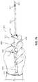
- the userhas the option of holding (and actuating) inserter 315 with a variety of grips.
- the usermay hold inserter 315 so that the index finger engages first grip 430 , the thumb engages second grip 435 or button actuator 485 , and/or the middle, ring and little finger wrap around the barrel of body 420 of handle 375 .
- This manner of holding inserter 315is somewhat analogous to the manner in which a user might hold a steak knife or a pool cue.
- FIG. 76the user may hold inserter 315 so that the index finger engages first grip 430 , the thumb engages second grip 435 or button actuator 485 , and/or the middle, ring and little finger wrap around the barrel of body 420 of handle 375 .
- This manner of holding inserter 315is somewhat analogous to the manner in which a user might hold a steak knife or a pool cue.
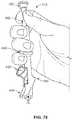
- inserter 315may hold inserter 315 so that the middle and ring fingers engage third grip 440 and the thumb engages end cap 483 .
- This manner of holding inserter 315is somewhat analogous to the manner in which a user might hold a syringe.
- the surgeonmay hold the inserter 315 like a ballpoint pen.
- the surgeonmay engage the extension 482 and/or the end cap 483 between thumb and index finger, with the other three fingers wrapped around handle 375 such that third grip 440 is positioned between two fingers (such as pinkie and ring fingers, as illustrated in FIGS. 78, 79 and 81 ).
- This gripallows for both rotation of extension 482 , and thus actuator 485 , and, by pressing on the proximal surface of the end cap 483 with the thumb ( FIG. 82 ), axial movement of the extension 482 , and thus pusher to deploy the anchors.
- FIG. 82illustrates the extension 482 and/or the end cap 483 between thumb and index finger, with the other three fingers wrapped around handle 375 such that third grip 440 is positioned between two fingers (such as pinkie and ring fingers, as illustrated in FIGS. 78, 79 and 81 ).
- This gripallows for both rotation of extension 482 , and thus actuator 485 , and
- the extension 482may be released while the actuator 485 is positioned within the second portion 455 , such that spring 484 automatically moves actuator 485 , and thus pusher 480 distally.
- spring 484may not have sufficient force to eject the distal anchor from shaft 370 . Such a spring force may decrease the risk of accidental deployment of the distal anchor, such that depression of the thumb on end cap 483 is required for actual deployment.
- first grip 430 and second grip 435 of handle 375indicate the rotational disposition of anchors 320 within shaft 370 even when the distal end of shaft 370 is disposed at a remote location within the body.
- first grip 430 and second grip 435 of handle 375also indicate the orientation of the curvature of shaft 370 .
- the present inventionincludes a method of packaging the inserter 315 including positioning the actuator 485 against the first stop 465 to prevent movement of the actuator 485 relative to the handle 375 , optionally sterilizing the inserter 315 and/or packaging, and packaging the inserter 315 in at least one layer of packaging.
- the inserter 315may also include the anchor assembly 310 positioned within the shaft 370 and ready for use.
- the packagingmay also include an instructions for use or surgical technique document detailing at least one surgical method for which inserter 315 may be used.
- anchor assembly 310may be modified, e.g., the configuration and/or number of anchors 320 may be modified, terminus knot 360 may comprise a knot different than that disclosed, slip knot 365 may comprise a slip knot different than that disclosed above, etc.
- terminus knot 360may comprise a knot different than that disclosed
- slip knot 365may comprise a slip knot different than that disclosed above, etc.
- configuration of inserter 315may be modified from that disclosed.
- the specificationmay have presented the method and/or process of the present invention as a particular sequence of steps. However, to the extent that the method or process does not rely on the particular order of steps set forth herein, the method or process should not be limited to the particular sequence of steps described. For example, any number of sutures may be prepared ahead of time. In addition, the advancement of the anchors within the cannula may occur before or after needle insertion. In addition, the delivery of the second anchor may not require that the needle be fully withdrawn; for example when two anchors are to be delivered through a single insertion site. As one of ordinary skill in the art would appreciate, other sequences of steps may be possible.
Landscapes
- Health & Medical Sciences (AREA)
- Life Sciences & Earth Sciences (AREA)
- Surgery (AREA)
- Heart & Thoracic Surgery (AREA)
- Engineering & Computer Science (AREA)
- Biomedical Technology (AREA)
- Nuclear Medicine, Radiotherapy & Molecular Imaging (AREA)
- Medical Informatics (AREA)
- Molecular Biology (AREA)
- Animal Behavior & Ethology (AREA)
- General Health & Medical Sciences (AREA)
- Public Health (AREA)
- Veterinary Medicine (AREA)
- Rheumatology (AREA)
- Surgical Instruments (AREA)
Abstract
Description
Claims (21)
Priority Applications (2)
| Application Number | Priority Date | Filing Date | Title |
|---|---|---|---|
| US15/604,071US10932769B2 (en) | 2016-05-26 | 2017-05-24 | System and method for all-inside suture fixation for implant attachment and soft tissue repair |
| US17/161,028US11696752B2 (en) | 2016-05-26 | 2021-01-28 | Systems and methods for all-inside suture fixation for implant attachment and soft tissue repair |
Applications Claiming Priority (3)
| Application Number | Priority Date | Filing Date | Title |
|---|---|---|---|
| US201662341744P | 2016-05-26 | 2016-05-26 | |
| US201662370167P | 2016-08-02 | 2016-08-02 | |
| US15/604,071US10932769B2 (en) | 2016-05-26 | 2017-05-24 | System and method for all-inside suture fixation for implant attachment and soft tissue repair |
Related Child Applications (1)
| Application Number | Title | Priority Date | Filing Date |
|---|---|---|---|
| US17/161,028ContinuationUS11696752B2 (en) | 2016-05-26 | 2021-01-28 | Systems and methods for all-inside suture fixation for implant attachment and soft tissue repair |
Publications (2)
| Publication Number | Publication Date |
|---|---|
| US20170340319A1 US20170340319A1 (en) | 2017-11-30 |
| US10932769B2true US10932769B2 (en) | 2021-03-02 |
Family
ID=58800697
Family Applications (2)
| Application Number | Title | Priority Date | Filing Date |
|---|---|---|---|
| US15/604,071Active2037-11-08US10932769B2 (en) | 2016-05-26 | 2017-05-24 | System and method for all-inside suture fixation for implant attachment and soft tissue repair |
| US17/161,028Active2037-09-19US11696752B2 (en) | 2016-05-26 | 2021-01-28 | Systems and methods for all-inside suture fixation for implant attachment and soft tissue repair |
Family Applications After (1)
| Application Number | Title | Priority Date | Filing Date |
|---|---|---|---|
| US17/161,028Active2037-09-19US11696752B2 (en) | 2016-05-26 | 2021-01-28 | Systems and methods for all-inside suture fixation for implant attachment and soft tissue repair |
Country Status (4)
| Country | Link |
|---|---|
| US (2) | US10932769B2 (en) |
| EP (1) | EP3248549B1 (en) |
| AU (1) | AU2017203494A1 (en) |
| CA (1) | CA2968651C (en) |
Cited By (2)
| Publication number | Priority date | Publication date | Assignee | Title |
|---|---|---|---|---|
| US20230114987A1 (en)* | 2021-10-07 | 2023-04-13 | Clemson University Research Foundation | Annulus repair devices, systems, and methods |
| US12239315B2 (en) | 2023-02-22 | 2025-03-04 | Arcus Medical Llc | Transvaginal lift device for prolapsed pelvic organ |
Families Citing this family (9)
| Publication number | Priority date | Publication date | Assignee | Title |
|---|---|---|---|---|
| AU2019271230B2 (en)* | 2018-05-17 | 2025-01-30 | Smith & Nephew Asia Pacific Pte Limited | Tissue repair device and method |
| WO2020069486A1 (en)* | 2018-09-28 | 2020-04-02 | Conmed Corporation | System for repairing soft tissue tears |
| US11064995B2 (en) | 2019-05-02 | 2021-07-20 | Arthrex, Inc. | Surgical device with trigger operated needle |
| US11723649B2 (en)* | 2020-07-28 | 2023-08-15 | Mentor Worldwide Llc | Quick, one-handed interrupted suture fixation for approximating tissue without the need to tie knots |
| EP4203806A4 (en)* | 2020-08-31 | 2024-10-16 | Healthium Medtech Limited | TISSUE REPAIR DEVICE AND METHOD FOR REPAIRING TISSUE BY USING IMPLANTS |
| US12109099B1 (en)* | 2020-09-04 | 2024-10-08 | Athena Surgical, LLC | Surgical implant delivery system and related methods |
| CN114587457B (en)* | 2022-03-18 | 2023-09-19 | 湖南省人民医院 | Meniscal suture device |
| CN116077110A (en)* | 2022-12-05 | 2023-05-09 | 杭州锐健马斯汀医疗器材有限公司 | Meniscus suture instrument |
| WO2024124005A1 (en)* | 2022-12-08 | 2024-06-13 | The Research Foundation For The State University Of New York | Single-handed ligation device |
Citations (195)
| Publication number | Priority date | Publication date | Assignee | Title |
|---|---|---|---|---|
| US3103666A (en) | 1961-12-28 | 1963-09-17 | Dennison Mfg Co | Tag attaching apparatus |
| US3399432A (en) | 1965-12-08 | 1968-09-03 | Dennison Mfg Co | Button attachment |
| US3527223A (en) | 1967-09-01 | 1970-09-08 | Melvin Shein | Ear stud and hollow piercer for insertion thereof |
| US3845772A (en) | 1973-09-17 | 1974-11-05 | D Smith | Retention suture device and method |
| US3875648A (en) | 1973-04-04 | 1975-04-08 | Dennison Mfg Co | Fastener attachment apparatus and method |
| US4235238A (en) | 1978-05-11 | 1980-11-25 | Olympus Optical Co., Ltd. | Apparatus for suturing coeliac tissues |
| GB2118474A (en) | 1982-04-15 | 1983-11-02 | Techmedica Inc | Medical staple device |
| EP0129442A1 (en) | 1983-06-20 | 1984-12-27 | Ethicon, Inc. | Method and apparatus for applying a fastener to tissue with a pair of hollow needles |
| US4493323A (en) | 1982-12-13 | 1985-01-15 | University Of Iowa Research Foundation | Suturing device and method for using same |
| WO1986003666A1 (en) | 1984-12-14 | 1986-07-03 | Klaus Draenert | Implant intended to bone reinforcement and to anchoring of tirefonds, implants and implant parts |
| WO1987001270A1 (en) | 1985-09-06 | 1987-03-12 | Acufex Microsurgical Inc. | Surgical fastener |
| EP0241240A2 (en) | 1986-04-07 | 1987-10-14 | E. Marlowe Goble | Suture anchor apparatus |
| US4705040A (en) | 1985-11-18 | 1987-11-10 | Medi-Tech, Incorporated | Percutaneous fixation of hollow organs |
| US4741330A (en) | 1983-05-19 | 1988-05-03 | Hayhurst John O | Method and apparatus for anchoring and manipulating cartilage |
| US4836205A (en) | 1988-03-21 | 1989-06-06 | Barrett Gene R | Grasper-stitcher device for arthroscopic anterior cruciate ligament repair |
| US4994074A (en) | 1990-02-01 | 1991-02-19 | Ethicon, Inc. | Copolymers of ε-caprolactone, glycolide and glycolic acid for suture coatings |
| US5085661A (en) | 1990-10-29 | 1992-02-04 | Gerald Moss | Surgical fastener implantation device |
| US5176691A (en) | 1990-09-11 | 1993-01-05 | Pierce Instruments, Inc. | Knot pusher |
| US5312422A (en) | 1992-07-16 | 1994-05-17 | Linvatec Corporation | Endoscopic suturing needle |
| US5380334A (en) | 1993-02-17 | 1995-01-10 | Smith & Nephew Dyonics, Inc. | Soft tissue anchors and systems for implantation |
| US5391182A (en) | 1993-08-03 | 1995-02-21 | Origin Medsystems, Inc. | Apparatus and method for closing puncture wounds |
| US5405352A (en) | 1991-04-09 | 1995-04-11 | Weston; Peter V. | Suture knot, method for its formation and use, and knot forming apparatus |
| US5417691A (en) | 1982-05-20 | 1995-05-23 | Hayhurst; John O. | Apparatus and method for manipulating and anchoring tissue |
| US5437680A (en) | 1987-05-14 | 1995-08-01 | Yoon; Inbae | Suturing method, apparatus and system for use in endoscopic procedures |
| US5443475A (en) | 1990-11-09 | 1995-08-22 | Arthrotek, Inc. | Surgical instrument |
| US5467786A (en) | 1992-12-10 | 1995-11-21 | William C. Allen | Method for repairing tears and incisions in soft tissue |
| US5470337A (en) | 1994-05-17 | 1995-11-28 | Moss; Gerald | Surgical fastener |
| EP0702933A1 (en) | 1988-04-20 | 1996-03-27 | HAYHURST, John O. | Manipulating and anchoring tissue |
| US5549631A (en) | 1993-05-14 | 1996-08-27 | Bonutti; Peter M. | Method of closing discontinuity in tissue |
| US5562684A (en) | 1994-10-11 | 1996-10-08 | Ethicon, Inc. | Surgical knot pusher device and improved method of forming knots |
| US5562689A (en) | 1993-08-20 | 1996-10-08 | United States Surgical Corporation | Apparatus and method for applying and adjusting an anchoring device |
| US5569305A (en) | 1993-05-14 | 1996-10-29 | Bonutti; Peter M. | Apparatus for anchoring a suture |
| US5601576A (en) | 1994-08-10 | 1997-02-11 | Heartport Inc. | Surgical knot pusher and method of use |
| US5601557A (en) | 1982-05-20 | 1997-02-11 | Hayhurst; John O. | Anchoring and manipulating tissue |
| US5601571A (en) | 1994-05-17 | 1997-02-11 | Moss; Gerald | Surgical fastener implantation device |
| US5626614A (en) | 1995-12-22 | 1997-05-06 | Applied Medical Resources Corporation | T-anchor suturing device and method for using same |
| US5667513A (en) | 1995-06-07 | 1997-09-16 | Smith & Nephew Dyonics Inc. | Soft tissue anchor delivery apparatus |
| US5702462A (en) | 1996-01-24 | 1997-12-30 | Oberlander; Michael | Method of meniscal repair |
| US5718717A (en) | 1996-08-19 | 1998-02-17 | Bonutti; Peter M. | Suture anchor |
| US5759189A (en) | 1997-02-25 | 1998-06-02 | Smith & Nephew Inc. | Knot pusher |
| US5801848A (en) | 1993-01-06 | 1998-09-01 | Fontech Ltd. | Process for transmitting and/or storing information |
| US5810848A (en) | 1996-08-21 | 1998-09-22 | Hayhurst; John O. | Suturing system |
| US5895395A (en) | 1997-07-17 | 1999-04-20 | Yeung; Teresa T. | Partial to full thickness suture device & method for endoscopic surgeries |
| US5928252A (en) | 1997-01-21 | 1999-07-27 | Regen Biologics, Inc. | Device and method for driving a needle and meniscal repair |
| US5941439A (en) | 1997-05-14 | 1999-08-24 | Mitek Surgical Products, Inc. | Applicator and method for deploying a surgical fastener in tissue |
| US5976127A (en) | 1998-01-14 | 1999-11-02 | Lax; Ronald | Soft tissue fixation devices |
| US6039753A (en) | 1998-07-16 | 2000-03-21 | Meislin; Robert | Single unit surgical fastener and method |
| US6047826A (en) | 1998-03-18 | 2000-04-11 | Ethicon, Inc. | Package tray for meniscal needle |
| US6056760A (en) | 1997-01-30 | 2000-05-02 | Nissho Corporation | Device for intracardiac suture |
| US6066146A (en) | 1998-06-24 | 2000-05-23 | Carroll; Brendan J. | Laparascopic incision closure device |
| US6071292A (en) | 1997-06-28 | 2000-06-06 | Transvascular, Inc. | Transluminal methods and devices for closing, forming attachments to, and/or forming anastomotic junctions in, luminal anatomical structures |
| US6156044A (en) | 1996-12-11 | 2000-12-05 | Ethicon, Inc. | Meniscal repair device |
| US6206895B1 (en) | 1999-07-13 | 2001-03-27 | Scion Cardio-Vascular, Inc. | Suture with toggle and delivery system |
| US6293961B2 (en) | 1998-12-30 | 2001-09-25 | Ethicon, Inc. | Suture locking device |
| US6306159B1 (en) | 1998-12-23 | 2001-10-23 | Depuy Orthopaedics, Inc. | Meniscal repair device |
| US6306156B1 (en) | 1997-11-20 | 2001-10-23 | Ron Clark | Meniscus repair anchor system |
| US20020019649A1 (en) | 1999-12-02 | 2002-02-14 | Smith & Nephew, Inc., Delaware Corporation | Closure device and method for tissue repair |
| US20020107532A1 (en)* | 2001-02-07 | 2002-08-08 | Jacqueline Huet-Olivier | Implantable system for anchoring stitching threads inside a bone tunnel and a kit therefor |
| US20020116012A1 (en) | 2001-02-16 | 2002-08-22 | May Thomas C. | Surgical knot pusher and method of use |
| US20020143342A1 (en) | 2000-04-28 | 2002-10-03 | Smith & Nephew, Inc. A Delaware Corporation | Cartilage grafting |
| US6488691B1 (en) | 1998-06-24 | 2002-12-03 | Brendan J. Carroll | Laparascopic incision closure device |
| US20020193811A1 (en) | 1993-07-12 | 2002-12-19 | Kwan-Ho Chan | Surgical repair kit and its method of use |
| US20030021827A1 (en) | 2001-07-16 | 2003-01-30 | Prasanna Malaviya | Hybrid biologic/synthetic porous extracellular matrix scaffolds |
| US20030023316A1 (en) | 2000-08-04 | 2003-01-30 | Brown Laura Jean | Hybrid biologic-synthetic bioabsorable scaffolds |
| US20030033021A1 (en) | 2001-07-16 | 2003-02-13 | Plouhar Pamela Lynn | Cartilage repair and regeneration scaffold and method |
| US20030032961A1 (en) | 2001-07-16 | 2003-02-13 | Pelo Mark Joseph | Devices from naturally occurring biologically derived materials |
| US20030036797A1 (en) | 2001-07-16 | 2003-02-20 | Prasanna Malaviya | Meniscus regeneration device and method |
| US20030036801A1 (en) | 2001-07-16 | 2003-02-20 | Schwartz Herbert E. | Cartilage repair apparatus and method |
| US20030049299A1 (en) | 2001-07-16 | 2003-03-13 | Prasanna Malaviya | Porous delivery scaffold and method |
| US20030078617A1 (en) | 2001-07-16 | 2003-04-24 | Schwartz Herbert E. | Unitary surgical device and method |
| US6554845B1 (en) | 2000-09-15 | 2003-04-29 | PARÉ Surgical, Inc. | Suturing apparatus and method |
| US20030130694A1 (en) | 1999-12-02 | 2003-07-10 | Ray Bojarski | Soft tissue attachment and repair |
| US6592609B1 (en) | 1999-08-09 | 2003-07-15 | Bonutti 2003 Trust-A | Method and apparatus for securing tissue |
| US20030158604A1 (en) | 1999-10-20 | 2003-08-21 | Cauthen Joseph C. | Spinal disc annulus reconstruction method and spinal disc annulus stent |
| US20030181928A1 (en) | 2000-10-06 | 2003-09-25 | Myocor, Inc. | Endovascular splinting devices and methods |
| US6626916B1 (en) | 1998-12-31 | 2003-09-30 | Teresa T. Yeung | Tissue fastening devices and methods for sustained holding strength |
| US6635073B2 (en) | 2000-05-03 | 2003-10-21 | Peter M. Bonutti | Method of securing body tissue |
| US20030204194A1 (en) | 2002-04-26 | 2003-10-30 | Bittar Edward S. | Meniscus and soft tissue repair device and method of use |
| US6656182B1 (en) | 1982-05-20 | 2003-12-02 | John O. Hayhurst | Tissue manipulation |
| US20030236535A1 (en) | 2002-05-08 | 2003-12-25 | Olympus Optical Co., Ltd. | Apparatus for ligating/suturing living tissues and system for resecting/suturing living tissues |
| US20040002734A1 (en) | 2002-06-26 | 2004-01-01 | Stryker Endoscopy, Inc. | Soft tissue repair system |
| US20040015186A1 (en) | 2002-07-19 | 2004-01-22 | Bittar Edward S. | Meniscal repair device and method of use |
| EP1408848A1 (en) | 1999-12-02 | 2004-04-21 | Smith & Nephew, Inc. | Wound closure devices and methods |
| JP2004515273A (en) | 2000-11-02 | 2004-05-27 | スミス アンド ネフュー インコーポレーテッド | Tissue repair closure device and tissue repair method |
| US20040127915A1 (en) | 2002-12-30 | 2004-07-01 | Fleenor Richard P. | Suture hoop system |
| US20040138683A1 (en) | 2003-01-09 | 2004-07-15 | Walter Shelton | Suture arrow device and method of using |
| US20040153074A1 (en) | 2003-02-05 | 2004-08-05 | Bojarski Raymond A. | Tissue anchor and insertion tool |
| US20040166169A1 (en) | 2002-07-15 | 2004-08-26 | Prasanna Malaviya | Porous extracellular matrix scaffold and method |
| US20040225183A1 (en) | 1999-06-25 | 2004-11-11 | Usgi Medical | Apparatus and methods for forming and securing gastrointestinal tissue folds |
| US20040243178A1 (en) | 2003-06-02 | 2004-12-02 | Linvatec Corporation | Push-in suture anchor, insertion tool, and method for inserting a push-in suture anchor |
| US20040249395A1 (en) | 2003-06-06 | 2004-12-09 | Olympus Corporation | Suturing instrument |
| US20040254598A1 (en) | 2003-06-16 | 2004-12-16 | Schumacher Brian S. | Suture cutter |
| US20040260343A1 (en) | 2003-02-04 | 2004-12-23 | Leclair Walter J. | T-type bone anchor |
| US20050090840A1 (en) | 2001-12-04 | 2005-04-28 | The Children's Medical Center Corporation | Tissue repair |
| US20050113851A1 (en) | 2002-05-17 | 2005-05-26 | Swain Christopher P. | Device for transfixing and joining tissue |
| US20050131313A1 (en) | 2003-12-16 | 2005-06-16 | Mikulka Thomas L. | Tissue sampling device and method |
| US20050159762A1 (en) | 2003-12-30 | 2005-07-21 | Juha-Pekka Nuutinen | Suture arrow device and installation device |
| US20050187577A1 (en) | 2004-02-24 | 2005-08-25 | David Selvitelli | Methods and devices for repairing tissue |
| US20050283246A1 (en) | 1999-08-13 | 2005-12-22 | Cauthen Joseph C Iii | Method and apparatus for the treatment of the intervertebral disc annulus |
| US20060025819A1 (en) | 2004-05-14 | 2006-02-02 | Nobis Rudolph H | T-type suture anchoring devices and methods of using same |
| US20060030884A1 (en) | 2002-03-14 | 2006-02-09 | Yeung Jeffrey E | Suture anchor and approximating device |
| US7004959B2 (en) | 1996-11-15 | 2006-02-28 | Bonutti Ip, Llc | Apparatus and method for use in positioning an anchor |
| US20060074438A1 (en) | 2002-04-09 | 2006-04-06 | Kwan-Ho Chan | Surgical repair kit and its method of use |
| US7025756B2 (en) | 1999-09-20 | 2006-04-11 | Ev 3 Sunnyvale, Inc. | Method of securing tissue |
| US20060100643A1 (en) | 2004-03-11 | 2006-05-11 | Laufer Michael D | Surgical fastening system |
| US20060161183A1 (en) | 2003-02-04 | 2006-07-20 | Sauer Jude S | Instrument for assisting in the remote placement of tied surgical knots and trimming of suture away from the knot and method of use |
| EP1685802A1 (en) | 2003-10-08 | 2006-08-02 | Olympus Corporation | Medical treatment instrument |
| US20060178680A1 (en)* | 2005-02-07 | 2006-08-10 | Regen Biologics, Inc. | System and method for all-inside suture fixation for implant attachment and soft tissue repair |
| US20060189993A1 (en) | 2004-11-09 | 2006-08-24 | Arthrotek, Inc. | Soft tissue conduit device |
| US20060190042A1 (en) | 2004-11-05 | 2006-08-24 | Arthrotek, Inc. | Tissue repair assembly |
| US7118583B2 (en) | 2001-10-23 | 2006-10-10 | Arthrex, Inc. | Meniscal suturing instrument and method |
| US20060265042A1 (en) | 2005-05-20 | 2006-11-23 | Exploramed Nc2, Inc. | Devices, systems and methods for retracting, lifting, compressing, supporting or repositioning tissues or anatomical structures |
| US7150750B2 (en) | 2002-01-10 | 2006-12-19 | Boston Scientific Scimed, Inc. | Method and device for endoscopic suturing |
| US20060293709A1 (en) | 2005-06-24 | 2006-12-28 | Bojarski Raymond A | Tissue repair device |
| US20070027476A1 (en) | 2005-02-07 | 2007-02-01 | Regen Biologics, Inc. | System and method for all-inside suture fixation for implant attachment and soft tissue repair |
| US20070049929A1 (en) | 2005-05-20 | 2007-03-01 | Catanese Joseph Iii | Apparatus and method for manipulating or retracting tissue and anatomical structure |
| US20070083236A1 (en) | 2005-06-24 | 2007-04-12 | Smith & Nephew, Inc. | Methods and devices for tissue repair |
| US20070088390A1 (en) | 2003-07-11 | 2007-04-19 | Endogun Medical Systems Ltd. | Surgical fasteners and devices for surgical fastening |
| US20070142846A1 (en) | 2005-05-20 | 2007-06-21 | Neotract, Inc. | Integrated handle assembly for anchor delivery system |
| US20070173865A1 (en) | 2004-03-04 | 2007-07-26 | Ran Oren | Suture manipulating and cutting implement |
| US20070213746A1 (en) | 2006-03-08 | 2007-09-13 | Martin Hahn | Medical knot pusher |
| US20070219567A1 (en) | 2006-03-15 | 2007-09-20 | Bayer Hanspeter R | Suture pushing apparatus |
| US20070270889A1 (en) | 2006-05-19 | 2007-11-22 | Conlon Sean P | Combination knotting element and suture anchor applicator |
| US20080009904A1 (en) | 2006-03-17 | 2008-01-10 | Bourque Barnard J | Soft Tissue Fixation |
| US7318833B2 (en) | 2001-12-19 | 2008-01-15 | Nmt Medical, Inc. | PFO closure device with flexible thrombogenic joint and improved dislodgement resistance |
| US20080033487A1 (en) | 2006-08-07 | 2008-02-07 | Bioduct, Llc | Medical device for repair of tissue and method for implantation and fixation |
| US20080033458A1 (en) | 2005-05-20 | 2008-02-07 | Neotract, Inc. | Multi-actuating trigger anchor delivery system |
| US20080039893A1 (en) | 2005-05-20 | 2008-02-14 | Neotract, Inc. | Multi-actuating trigger anchor delivery system |
| US7347863B2 (en) | 2004-05-07 | 2008-03-25 | Usgi Medical, Inc. | Apparatus and methods for manipulating and securing tissue |
| US7361180B2 (en) | 2004-05-07 | 2008-04-22 | Usgi Medical, Inc. | Apparatus for manipulating and securing tissue |
| US7390329B2 (en) | 2004-05-07 | 2008-06-24 | Usgi Medical, Inc. | Methods for grasping and cinching tissue anchors |
| WO2009014996A2 (en) | 2007-07-23 | 2009-01-29 | Zimmer Orthobiologics, Inc. | Medical devices and methods for cutting and suturing biological tissue |
| US20090062854A1 (en) | 2004-11-05 | 2009-03-05 | Biomet Sports Medicine, Llc | Method and apparatus for coupling soft tissue to bone |
| EP2098172A1 (en) | 2008-03-04 | 2009-09-09 | Arthrex, Inc. | System for meniscal repair using suture implant cinch construct |
| US7594922B1 (en) | 2005-04-07 | 2009-09-29 | Medicine Lodge, Inc | System and method for meniscal repair through a meniscal capsular tunnel |
| WO2009124215A1 (en) | 2008-04-02 | 2009-10-08 | Sequent Tissue Repair, Inc. | Method and apparatus for meniscal repair |
| US7601659B2 (en) | 2005-04-01 | 2009-10-13 | E.I. Du Pont De Nemours And Company | Dewatering fabrics |
| US7601165B2 (en) | 2006-09-29 | 2009-10-13 | Biomet Sports Medicine, Llc | Method and apparatus for forming a self-locking adjustable suture loop |
| US20090255544A1 (en)* | 2008-03-21 | 2009-10-15 | Usgi Medical, Inc. | Devices and methods for the endolumenal treatment of obesity |
| US7608098B1 (en) | 2004-11-09 | 2009-10-27 | Biomet Sports Medicine, Llc | Bone fixation device |
| US7608092B1 (en) | 2004-02-20 | 2009-10-27 | Biomet Sports Medicince, LLC | Method and apparatus for performing meniscus repair |
| US7621925B2 (en) | 2004-05-07 | 2009-11-24 | Usgi Medical, Inc. | Needle assembly for tissue manipulation |
| US20100094425A1 (en) | 2008-10-14 | 2010-04-15 | Anulex Technologies, Inc. | Method and apparatus for the treatment of the intervertebral disc annulus |
| US20100130989A1 (en)* | 2008-11-26 | 2010-05-27 | Smith & Nephew, Inc. | Tissue Repair Device |
| US7736374B2 (en) | 2004-05-07 | 2010-06-15 | Usgi Medical, Inc. | Tissue manipulation and securement system |
| US7749250B2 (en) | 2006-02-03 | 2010-07-06 | Biomet Sports Medicine, Llc | Soft tissue repair assembly and associated method |
| US7857830B2 (en) | 2006-02-03 | 2010-12-28 | Biomet Sports Medicine, Llc | Soft tissue repair and conduit device |
| US20110009872A1 (en) | 2007-10-29 | 2011-01-13 | Tigenix Limited | Implant delivery device and method |
| EP2277457A1 (en) | 2009-07-24 | 2011-01-26 | DePuy Mitek, Inc. | Devices for repairing and anchoring damaged tissue |
| US7905903B2 (en) | 2006-02-03 | 2011-03-15 | Biomet Sports Medicine, Llc | Method for tissue fixation |
| US7905904B2 (en) | 2006-02-03 | 2011-03-15 | Biomet Sports Medicine, Llc | Soft tissue repair device and associated methods |
| US7909851B2 (en) | 2006-02-03 | 2011-03-22 | Biomet Sports Medicine, Llc | Soft tissue repair device and associated methods |
| US7914539B2 (en) | 2004-11-09 | 2011-03-29 | Biomet Sports Medicine, Llc | Tissue fixation device |
| US7959650B2 (en) | 2006-09-29 | 2011-06-14 | Biomet Sports Medicine, Llc | Adjustable knotless loops |
| US20110172701A1 (en)* | 2010-01-11 | 2011-07-14 | Anulex Technologies, Inc. | Intervertebral disc annulus repair system and method |
| US8034090B2 (en) | 2004-11-09 | 2011-10-11 | Biomet Sports Medicine, Llc | Tissue fixation device |
| US8057511B2 (en) | 2004-05-07 | 2011-11-15 | Usgi Medical, Inc. | Apparatus and methods for positioning and securing anchors |
| US8088130B2 (en) | 2006-02-03 | 2012-01-03 | Biomet Sports Medicine, Llc | Method and apparatus for coupling soft tissue to a bone |
| US8118836B2 (en) | 2004-11-05 | 2012-02-21 | Biomet Sports Medicine, Llc | Method and apparatus for coupling soft tissue to a bone |
| US8137382B2 (en) | 2004-11-05 | 2012-03-20 | Biomet Sports Medicine, Llc | Method and apparatus for coupling anatomical features |
| DE102010060899A1 (en) | 2010-11-30 | 2012-05-31 | Glaser Gmbh Surgical Instruments | Device for meniscal repair |
| US8202282B2 (en) | 2002-02-04 | 2012-06-19 | Arthrex, Inc. | Knot pusher and suture retriever |
| US8216252B2 (en) | 2004-05-07 | 2012-07-10 | Usgi Medical, Inc. | Tissue manipulation and securement system |
| US8241305B2 (en) | 2008-05-08 | 2012-08-14 | Biomet Sports Medicine, Llc | Method for repairing a meniscal tear |
| US8251998B2 (en) | 2006-08-16 | 2012-08-28 | Biomet Sports Medicine, Llc | Chondral defect repair |
| US8257394B2 (en) | 2004-05-07 | 2012-09-04 | Usgi Medical, Inc. | Apparatus and methods for positioning and securing anchors |
| US8298262B2 (en) | 2006-02-03 | 2012-10-30 | Biomet Sports Medicine, Llc | Method for tissue fixation |
| US8303604B2 (en) | 2004-11-05 | 2012-11-06 | Biomet Sports Medicine, Llc | Soft tissue repair device and method |
| US8343227B2 (en) | 2009-05-28 | 2013-01-01 | Biomet Manufacturing Corp. | Knee prosthesis assembly with ligament link |
| US8361113B2 (en) | 2006-02-03 | 2013-01-29 | Biomet Sports Medicine, Llc | Method and apparatus for coupling soft tissue to a bone |
| US8444657B2 (en) | 2004-05-07 | 2013-05-21 | Usgi Medical, Inc. | Apparatus and methods for rapid deployment of tissue anchors |
| US20130144337A1 (en) | 2011-11-10 | 2013-06-06 | Biomet Sports Medicine, Llc | Method for Coupling Soft Tissue to a Bone |
| WO2013099671A1 (en) | 2011-12-26 | 2013-07-04 | 古河電気工業株式会社 | Reflector, method for manufacturing reflector, and backlight panel |
| US8500818B2 (en) | 2006-09-29 | 2013-08-06 | Biomet Manufacturing, Llc | Knee prosthesis assembly with ligament link |
| US8506597B2 (en) | 2011-10-25 | 2013-08-13 | Biomet Sports Medicine, Llc | Method and apparatus for interosseous membrane reconstruction |
| US8562645B2 (en) | 2006-09-29 | 2013-10-22 | Biomet Sports Medicine, Llc | Method and apparatus for forming a self-locking adjustable loop |
| US8562647B2 (en) | 2006-09-29 | 2013-10-22 | Biomet Sports Medicine, Llc | Method and apparatus for securing soft tissue to bone |
| US8574235B2 (en) | 2006-02-03 | 2013-11-05 | Biomet Sports Medicine, Llc | Method for trochanteric reattachment |
| US8597327B2 (en) | 2006-02-03 | 2013-12-03 | Biomet Manufacturing, Llc | Method and apparatus for sternal closure |
| WO2014039610A1 (en) | 2012-09-07 | 2014-03-13 | Ceterix Orthopaedics, Inc. | Pre-tied surgical knots for use with suture passers |
| US8790369B2 (en) | 2009-07-24 | 2014-07-29 | Depuy Mitek, Llc | Apparatus and method for repairing tissue |
| US8814903B2 (en) | 2009-07-24 | 2014-08-26 | Depuy Mitek, Llc | Methods and devices for repairing meniscal tissue |
| US8814904B2 (en) | 2010-10-26 | 2014-08-26 | Ziptek LLC. | Surgical suture system |
| US8828054B2 (en) | 2008-04-02 | 2014-09-09 | Liavatec Corporation | Method and apparatus for meniscal repair |
| US20140276987A1 (en) | 2011-01-10 | 2014-09-18 | Justin D. Saliman | Suture methods for forming locking loops stitches |
| US8876842B2 (en) | 2006-05-22 | 2014-11-04 | Covidien Lp | Meniscal repair device |
| US9084597B2 (en) | 2012-03-09 | 2015-07-21 | Smith & Nephew, Inc. | Suture-based knotless repair |
| US20150223803A1 (en) | 2014-02-12 | 2015-08-13 | Roy H. Trawick | Meniscal repair device |
| US9173645B2 (en) | 2010-04-27 | 2015-11-03 | DePuy Synthes Products, Inc. | Anchor assembly including expandable anchor |
| CN105078522A (en) | 2015-08-28 | 2015-11-25 | 南京英麦德医疗科技有限公司 | Soft tissue suturing apparatus |
| US9220493B2 (en) | 2009-02-06 | 2015-12-29 | Karl Storz Gmbh & Co. Kg | Suture anchor kit |
| US9247935B2 (en) | 2013-09-23 | 2016-02-02 | Ceterix Orthopaedics, Inc. | Arthroscopic knot pusher and suture cutter |
| US9277914B2 (en) | 2012-09-21 | 2016-03-08 | Boston Scientific Neuromodulation Corporation | Tissue fixation delivery apparatus |
| US20160120535A1 (en) | 2014-10-29 | 2016-05-05 | Smith & Nephew, Inc. | Modular tissue repair kit and devices and method related thereto |
| US9351722B2 (en) | 2011-12-23 | 2016-05-31 | Arthrex, Inc. | Drive system for tissue repair |
Family Cites Families (3)
| Publication number | Priority date | Publication date | Assignee | Title |
|---|---|---|---|---|
| US20120316648A1 (en)* | 1999-08-18 | 2012-12-13 | Intrinsic Therapeutics, Inc. | Intervertebral disc reinforcement systems |
| US7819897B2 (en)* | 2001-11-20 | 2010-10-26 | Sofradim Production | Fastener for fixing a prosthesis, and device for delivering this fastener |
| US10456267B2 (en)* | 2011-11-23 | 2019-10-29 | Medos International Sarl | Lateral cage stabilization |
- 2017
- 2017-05-24USUS15/604,071patent/US10932769B2/enactiveActive
- 2017-05-25AUAU2017203494Apatent/AU2017203494A1/ennot_activeAbandoned
- 2017-05-25CACA2968651Apatent/CA2968651C/ennot_activeExpired - Fee Related
- 2017-05-26EPEP17173055.9Apatent/EP3248549B1/enactiveActive
- 2021
- 2021-01-28USUS17/161,028patent/US11696752B2/enactiveActive
Patent Citations (294)
| Publication number | Priority date | Publication date | Assignee | Title |
|---|---|---|---|---|
| US3103666A (en) | 1961-12-28 | 1963-09-17 | Dennison Mfg Co | Tag attaching apparatus |
| US3399432A (en) | 1965-12-08 | 1968-09-03 | Dennison Mfg Co | Button attachment |
| US3527223A (en) | 1967-09-01 | 1970-09-08 | Melvin Shein | Ear stud and hollow piercer for insertion thereof |
| US3875648A (en) | 1973-04-04 | 1975-04-08 | Dennison Mfg Co | Fastener attachment apparatus and method |
| US3845772A (en) | 1973-09-17 | 1974-11-05 | D Smith | Retention suture device and method |
| US4235238A (en) | 1978-05-11 | 1980-11-25 | Olympus Optical Co., Ltd. | Apparatus for suturing coeliac tissues |
| GB2118474A (en) | 1982-04-15 | 1983-11-02 | Techmedica Inc | Medical staple device |
| US5601557A (en) | 1982-05-20 | 1997-02-11 | Hayhurst; John O. | Anchoring and manipulating tissue |
| US5417691A (en) | 1982-05-20 | 1995-05-23 | Hayhurst; John O. | Apparatus and method for manipulating and anchoring tissue |
| USRE43143E1 (en) | 1982-05-20 | 2012-01-24 | Hayhurst John O | Tissue manipulation |
| US6656182B1 (en) | 1982-05-20 | 2003-12-02 | John O. Hayhurst | Tissue manipulation |
| US4493323A (en) | 1982-12-13 | 1985-01-15 | University Of Iowa Research Foundation | Suturing device and method for using same |
| US4741330A (en) | 1983-05-19 | 1988-05-03 | Hayhurst John O | Method and apparatus for anchoring and manipulating cartilage |
| EP0129442A1 (en) | 1983-06-20 | 1984-12-27 | Ethicon, Inc. | Method and apparatus for applying a fastener to tissue with a pair of hollow needles |
| WO1986003666A1 (en) | 1984-12-14 | 1986-07-03 | Klaus Draenert | Implant intended to bone reinforcement and to anchoring of tirefonds, implants and implant parts |
| WO1987001270A1 (en) | 1985-09-06 | 1987-03-12 | Acufex Microsurgical Inc. | Surgical fastener |
| US4669473A (en) | 1985-09-06 | 1987-06-02 | Acufex Microsurgical, Inc. | Surgical fastener |
| US4705040A (en) | 1985-11-18 | 1987-11-10 | Medi-Tech, Incorporated | Percutaneous fixation of hollow organs |
| EP0415915A1 (en) | 1986-04-04 | 1991-03-13 | John O Hayhurst | TREATMENT AND FIXING OF TISSUE. |
| EP0241240A2 (en) | 1986-04-07 | 1987-10-14 | E. Marlowe Goble | Suture anchor apparatus |
| US5437680A (en) | 1987-05-14 | 1995-08-01 | Yoon; Inbae | Suturing method, apparatus and system for use in endoscopic procedures |
| US4836205A (en) | 1988-03-21 | 1989-06-06 | Barrett Gene R | Grasper-stitcher device for arthroscopic anterior cruciate ligament repair |
| EP0702933A1 (en) | 1988-04-20 | 1996-03-27 | HAYHURST, John O. | Manipulating and anchoring tissue |
| US4994074A (en) | 1990-02-01 | 1991-02-19 | Ethicon, Inc. | Copolymers of ε-caprolactone, glycolide and glycolic acid for suture coatings |
| US5176691A (en) | 1990-09-11 | 1993-01-05 | Pierce Instruments, Inc. | Knot pusher |
| US5085661A (en) | 1990-10-29 | 1992-02-04 | Gerald Moss | Surgical fastener implantation device |
| US5649947A (en) | 1990-11-09 | 1997-07-22 | Arthrotek, Inc. | Surgical instrument |
| US5443475A (en) | 1990-11-09 | 1995-08-22 | Arthrotek, Inc. | Surgical instrument |
| US5405352A (en) | 1991-04-09 | 1995-04-11 | Weston; Peter V. | Suture knot, method for its formation and use, and knot forming apparatus |
| US5312422A (en) | 1992-07-16 | 1994-05-17 | Linvatec Corporation | Endoscopic suturing needle |
| US5467786A (en) | 1992-12-10 | 1995-11-21 | William C. Allen | Method for repairing tears and incisions in soft tissue |
| US5801848A (en) | 1993-01-06 | 1998-09-01 | Fontech Ltd. | Process for transmitting and/or storing information |
| US5380334A (en) | 1993-02-17 | 1995-01-10 | Smith & Nephew Dyonics, Inc. | Soft tissue anchors and systems for implantation |
| US5601558A (en) | 1993-02-17 | 1997-02-11 | Smith & Nephew Endoscopy, Inc. | Soft tissue anchors and systems for implantation |
| US5569305A (en) | 1993-05-14 | 1996-10-29 | Bonutti; Peter M. | Apparatus for anchoring a suture |
| US5549631A (en) | 1993-05-14 | 1996-08-27 | Bonutti; Peter M. | Method of closing discontinuity in tissue |
| US6500195B2 (en) | 1993-05-14 | 2002-12-31 | Peter M. Bonutti | Method and apparatus for anchoring a suture |
| US6932826B2 (en) | 1993-07-12 | 2005-08-23 | Kwan-Ho Chan | Surgical repair kit and its method of use |
| US20050165418A1 (en) | 1993-07-12 | 2005-07-28 | Kwan-Ho Chan | Surgical repair kit and its method of use |
| US7108700B2 (en) | 1993-07-12 | 2006-09-19 | Kwan-Ho Chan | Surgical repair kit and its method of use |
| US20020193811A1 (en) | 1993-07-12 | 2002-12-19 | Kwan-Ho Chan | Surgical repair kit and its method of use |
| US5391182A (en) | 1993-08-03 | 1995-02-21 | Origin Medsystems, Inc. | Apparatus and method for closing puncture wounds |
| US5562689A (en) | 1993-08-20 | 1996-10-08 | United States Surgical Corporation | Apparatus and method for applying and adjusting an anchoring device |
| US5601571A (en) | 1994-05-17 | 1997-02-11 | Moss; Gerald | Surgical fastener implantation device |
| US5470337A (en) | 1994-05-17 | 1995-11-28 | Moss; Gerald | Surgical fastener |
| US5601576A (en) | 1994-08-10 | 1997-02-11 | Heartport Inc. | Surgical knot pusher and method of use |
| US5562684A (en) | 1994-10-11 | 1996-10-08 | Ethicon, Inc. | Surgical knot pusher device and improved method of forming knots |
| US5667513A (en) | 1995-06-07 | 1997-09-16 | Smith & Nephew Dyonics Inc. | Soft tissue anchor delivery apparatus |
| US5626614A (en) | 1995-12-22 | 1997-05-06 | Applied Medical Resources Corporation | T-anchor suturing device and method for using same |
| US5702462A (en) | 1996-01-24 | 1997-12-30 | Oberlander; Michael | Method of meniscal repair |
| US6572635B1 (en) | 1996-08-19 | 2003-06-03 | Bonutti 2003 Trust-A | Suture anchor |
| US5980559A (en) | 1996-08-19 | 1999-11-09 | Bonutti; Peter M. | Suture anchor |
| US6955683B2 (en) | 1996-08-19 | 2005-10-18 | Bonutti Ip, Llc | Tissue fixation device |
| US5718717A (en) | 1996-08-19 | 1998-02-17 | Bonutti; Peter M. | Suture anchor |
| US5810848A (en) | 1996-08-21 | 1998-09-22 | Hayhurst; John O. | Suturing system |
| US7004959B2 (en) | 1996-11-15 | 2006-02-28 | Bonutti Ip, Llc | Apparatus and method for use in positioning an anchor |
| US6156044A (en) | 1996-12-11 | 2000-12-05 | Ethicon, Inc. | Meniscal repair device |
| US5928252A (en) | 1997-01-21 | 1999-07-27 | Regen Biologics, Inc. | Device and method for driving a needle and meniscal repair |
| US6056760A (en) | 1997-01-30 | 2000-05-02 | Nissho Corporation | Device for intracardiac suture |
| US5759189A (en) | 1997-02-25 | 1998-06-02 | Smith & Nephew Inc. | Knot pusher |
| US5941439A (en) | 1997-05-14 | 1999-08-24 | Mitek Surgical Products, Inc. | Applicator and method for deploying a surgical fastener in tissue |
| US7056325B1 (en) | 1997-06-28 | 2006-06-06 | Medtronic Vascular, Inc. | Transluminal methods and devices for closing, forming attachments to, and/or forming anastomotic junctions in, luminal anatomical structures |
| US6287317B1 (en) | 1997-06-28 | 2001-09-11 | Transvascular, Inc. | Transluminal methods and devices for closing, forming attachments to, and/or forming anastomotic junctions in, luminal anatomical structures |
| US6071292A (en) | 1997-06-28 | 2000-06-06 | Transvascular, Inc. | Transluminal methods and devices for closing, forming attachments to, and/or forming anastomotic junctions in, luminal anatomical structures |
| US6491707B2 (en) | 1997-06-28 | 2002-12-10 | Transvascular, Inc. | Transluminal methods and devices for closing, forming attachments to, and/or forming anastomotic junctions in, luminal anatomical structures |
| US5895395A (en) | 1997-07-17 | 1999-04-20 | Yeung; Teresa T. | Partial to full thickness suture device & method for endoscopic surgeries |
| US6306156B1 (en) | 1997-11-20 | 2001-10-23 | Ron Clark | Meniscus repair anchor system |
| US5976127A (en) | 1998-01-14 | 1999-11-02 | Lax; Ronald | Soft tissue fixation devices |
| US6047826A (en) | 1998-03-18 | 2000-04-11 | Ethicon, Inc. | Package tray for meniscal needle |
| US6066146A (en) | 1998-06-24 | 2000-05-23 | Carroll; Brendan J. | Laparascopic incision closure device |
| US6488691B1 (en) | 1998-06-24 | 2002-12-03 | Brendan J. Carroll | Laparascopic incision closure device |
| US6039753A (en) | 1998-07-16 | 2000-03-21 | Meislin; Robert | Single unit surgical fastener and method |
| US6306159B1 (en) | 1998-12-23 | 2001-10-23 | Depuy Orthopaedics, Inc. | Meniscal repair device |
| US8323315B2 (en) | 1998-12-30 | 2012-12-04 | Depuy Mitek, Inc. | Suture locking device |
| US6319271B1 (en) | 1998-12-30 | 2001-11-20 | Depuy Orthopaedics, Inc. | Suture locking device |
| US8512374B2 (en) | 1998-12-30 | 2013-08-20 | Depuy Mitek, Llc | Soft tissue locking device |
| US6432123B2 (en) | 1998-12-30 | 2002-08-13 | Ethicon, Inc. | Suture locking device |
| US7846181B2 (en) | 1998-12-30 | 2010-12-07 | Depuy Mitek, Inc. | Suture locking device |
| US7033380B2 (en) | 1998-12-30 | 2006-04-25 | Ethicon, Inc. | Suture locking device |
| US6293961B2 (en) | 1998-12-30 | 2001-09-25 | Ethicon, Inc. | Suture locking device |
| US6626916B1 (en) | 1998-12-31 | 2003-09-30 | Teresa T. Yeung | Tissue fastening devices and methods for sustained holding strength |
| US20040225183A1 (en) | 1999-06-25 | 2004-11-11 | Usgi Medical | Apparatus and methods for forming and securing gastrointestinal tissue folds |
| US6319263B1 (en) | 1999-07-13 | 2001-11-20 | Scion Cardio-Vascular, Inc. | Suture with toggle and delivery system |
| US6730112B2 (en) | 1999-07-13 | 2004-05-04 | Scion Cardio-Vascular, Inc. | Suture with toggle and delivery system |
| US6206895B1 (en) | 1999-07-13 | 2001-03-27 | Scion Cardio-Vascular, Inc. | Suture with toggle and delivery system |
| US6592609B1 (en) | 1999-08-09 | 2003-07-15 | Bonutti 2003 Trust-A | Method and apparatus for securing tissue |
| US20050283246A1 (en) | 1999-08-13 | 2005-12-22 | Cauthen Joseph C Iii | Method and apparatus for the treatment of the intervertebral disc annulus |
| US7025756B2 (en) | 1999-09-20 | 2006-04-11 | Ev 3 Sunnyvale, Inc. | Method of securing tissue |
| US20030158604A1 (en) | 1999-10-20 | 2003-08-21 | Cauthen Joseph C. | Spinal disc annulus reconstruction method and spinal disc annulus stent |
| US7993405B2 (en) | 1999-10-20 | 2011-08-09 | Anulex Technologies, Inc. | Spinal disc annulus repair system and methods |
| EP1408848A1 (en) | 1999-12-02 | 2004-04-21 | Smith & Nephew, Inc. | Wound closure devices and methods |
| US9295461B2 (en) | 1999-12-02 | 2016-03-29 | Smith & Nephew, Inc. | Methods for tissue repair |
| US20140350599A1 (en) | 1999-12-02 | 2014-11-27 | Smith & Nephew, Inc. | Closure device and method for tissue repair |
| US8834524B2 (en) | 1999-12-02 | 2014-09-16 | Smith & Nephew, Inc. | Closure device and method for tissue repair |
| US8512375B2 (en) | 1999-12-02 | 2013-08-20 | Smith & Nephew, Inc. | Closure device and method for tissue repair |
| US20100114161A1 (en) | 1999-12-02 | 2010-05-06 | Smith & Nephew, Inc. | Apparatus for Tissue Repair |
| US20030130694A1 (en) | 1999-12-02 | 2003-07-10 | Ray Bojarski | Soft tissue attachment and repair |
| US20020019649A1 (en) | 1999-12-02 | 2002-02-14 | Smith & Nephew, Inc., Delaware Corporation | Closure device and method for tissue repair |
| US20130144314A1 (en) | 1999-12-02 | 2013-06-06 | Raymond A. Bojarski | Apparatus for tissue repair |
| US20050283192A1 (en) | 1999-12-02 | 2005-12-22 | Torrie Paul A | Closure device and method for tissue repair |
| US7153312B1 (en) | 1999-12-02 | 2006-12-26 | Smith & Nephew Inc. | Closure device and method for tissue repair |
| US7887551B2 (en) | 1999-12-02 | 2011-02-15 | Smith & Nephew, Inc. | Soft tissue attachment and repair |
| US8366744B2 (en) | 1999-12-02 | 2013-02-05 | Smith & Nephew, Inc. | Apparatus for tissue repair |
| US9220494B2 (en) | 1999-12-02 | 2015-12-29 | Smith & Nephew, Inc. | Methods for tissue repair |
| US7651509B2 (en) | 1999-12-02 | 2010-01-26 | Smith & Nephew, Inc. | Methods and devices for tissue repair |
| US20050033363A1 (en) | 1999-12-02 | 2005-02-10 | Ray Bojarski | Methods and devices for tissue repair |
| US20020143342A1 (en) | 2000-04-28 | 2002-10-03 | Smith & Nephew, Inc. A Delaware Corporation | Cartilage grafting |
| US7192431B2 (en) | 2000-04-28 | 2007-03-20 | Smith & Nephew, Inc. | Cartilage grafting |
| US8814902B2 (en) | 2000-05-03 | 2014-08-26 | Bonutti Skeletal Innovations Llc | Method of securing body tissue |
| US6635073B2 (en) | 2000-05-03 | 2003-10-21 | Peter M. Bonutti | Method of securing body tissue |
| US7087073B2 (en) | 2000-05-03 | 2006-08-08 | Marctec, Llc | Method of securing body tissue |
| US20030023316A1 (en) | 2000-08-04 | 2003-01-30 | Brown Laura Jean | Hybrid biologic-synthetic bioabsorable scaffolds |
| JP2004508128A (en) | 2000-09-15 | 2004-03-18 | パレ サージカル インコーポレイテッド | Improved suturing device and method |
| US6554845B1 (en) | 2000-09-15 | 2003-04-29 | PARÉ Surgical, Inc. | Suturing apparatus and method |
| US20030181928A1 (en) | 2000-10-06 | 2003-09-25 | Myocor, Inc. | Endovascular splinting devices and methods |
| JP2004515273A (en) | 2000-11-02 | 2004-05-27 | スミス アンド ネフュー インコーポレーテッド | Tissue repair closure device and tissue repair method |
| US20020107532A1 (en)* | 2001-02-07 | 2002-08-08 | Jacqueline Huet-Olivier | Implantable system for anchoring stitching threads inside a bone tunnel and a kit therefor |
| US20020116012A1 (en) | 2001-02-16 | 2002-08-22 | May Thomas C. | Surgical knot pusher and method of use |
| US6884249B2 (en) | 2001-02-16 | 2005-04-26 | Depuy Mitek, Inc. | Surgical knot pusher and method of use |
| US20050033325A1 (en) | 2001-02-16 | 2005-02-10 | Ethicon, Inc. | Surgical knot pusher and method of use |
| US20030021827A1 (en) | 2001-07-16 | 2003-01-30 | Prasanna Malaviya | Hybrid biologic/synthetic porous extracellular matrix scaffolds |
| US20030049299A1 (en) | 2001-07-16 | 2003-03-13 | Prasanna Malaviya | Porous delivery scaffold and method |
| US20030033021A1 (en) | 2001-07-16 | 2003-02-13 | Plouhar Pamela Lynn | Cartilage repair and regeneration scaffold and method |
| US20030032961A1 (en) | 2001-07-16 | 2003-02-13 | Pelo Mark Joseph | Devices from naturally occurring biologically derived materials |
| US20030036797A1 (en) | 2001-07-16 | 2003-02-20 | Prasanna Malaviya | Meniscus regeneration device and method |
| US20030036801A1 (en) | 2001-07-16 | 2003-02-20 | Schwartz Herbert E. | Cartilage repair apparatus and method |
| US20030078617A1 (en) | 2001-07-16 | 2003-04-24 | Schwartz Herbert E. | Unitary surgical device and method |
| US7118583B2 (en) | 2001-10-23 | 2006-10-10 | Arthrex, Inc. | Meniscal suturing instrument and method |
| US20050090840A1 (en) | 2001-12-04 | 2005-04-28 | The Children's Medical Center Corporation | Tissue repair |
| US7318833B2 (en) | 2001-12-19 | 2008-01-15 | Nmt Medical, Inc. | PFO closure device with flexible thrombogenic joint and improved dislodgement resistance |
| US7150750B2 (en) | 2002-01-10 | 2006-12-19 | Boston Scientific Scimed, Inc. | Method and device for endoscopic suturing |
| US8202282B2 (en) | 2002-02-04 | 2012-06-19 | Arthrex, Inc. | Knot pusher and suture retriever |
| US20060030884A1 (en) | 2002-03-14 | 2006-02-09 | Yeung Jeffrey E | Suture anchor and approximating device |
| US20060074438A1 (en) | 2002-04-09 | 2006-04-06 | Kwan-Ho Chan | Surgical repair kit and its method of use |
| US20030204194A1 (en) | 2002-04-26 | 2003-10-30 | Bittar Edward S. | Meniscus and soft tissue repair device and method of use |
| US6997933B2 (en) | 2002-04-26 | 2006-02-14 | Bittar Edward S | Meniscus and soft tissue repair device and method of use |
| US20030236535A1 (en) | 2002-05-08 | 2003-12-25 | Olympus Optical Co., Ltd. | Apparatus for ligating/suturing living tissues and system for resecting/suturing living tissues |
| US20050113851A1 (en) | 2002-05-17 | 2005-05-26 | Swain Christopher P. | Device for transfixing and joining tissue |
| US20060064126A1 (en) | 2002-06-26 | 2006-03-23 | Fallin T W | Soft tissue repair system |
| US20040002734A1 (en) | 2002-06-26 | 2004-01-01 | Stryker Endoscopy, Inc. | Soft tissue repair system |
| US6972027B2 (en) | 2002-06-26 | 2005-12-06 | Stryker Endoscopy | Soft tissue repair system |
| US20040166169A1 (en) | 2002-07-15 | 2004-08-26 | Prasanna Malaviya | Porous extracellular matrix scaffold and method |
| US20040015186A1 (en) | 2002-07-19 | 2004-01-22 | Bittar Edward S. | Meniscal repair device and method of use |
| WO2004037094A2 (en) | 2002-10-23 | 2004-05-06 | Smith & Nephew, Inc. | Soft tissue attachment and repair |
| US20040127915A1 (en) | 2002-12-30 | 2004-07-01 | Fleenor Richard P. | Suture hoop system |
| US20040138683A1 (en) | 2003-01-09 | 2004-07-15 | Walter Shelton | Suture arrow device and method of using |
| US20040260343A1 (en) | 2003-02-04 | 2004-12-23 | Leclair Walter J. | T-type bone anchor |
| US20060161183A1 (en) | 2003-02-04 | 2006-07-20 | Sauer Jude S | Instrument for assisting in the remote placement of tied surgical knots and trimming of suture away from the knot and method of use |
| US20040153074A1 (en) | 2003-02-05 | 2004-08-05 | Bojarski Raymond A. | Tissue anchor and insertion tool |
| US7320701B2 (en) | 2003-06-02 | 2008-01-22 | Linvatec Corporation | Push-in suture anchor, insertion tool, and method for inserting a push-in suture anchor |
| US20040243178A1 (en) | 2003-06-02 | 2004-12-02 | Linvatec Corporation | Push-in suture anchor, insertion tool, and method for inserting a push-in suture anchor |
| US20040249395A1 (en) | 2003-06-06 | 2004-12-09 | Olympus Corporation | Suturing instrument |
| US20040254598A1 (en) | 2003-06-16 | 2004-12-16 | Schumacher Brian S. | Suture cutter |
| US20070088390A1 (en) | 2003-07-11 | 2007-04-19 | Endogun Medical Systems Ltd. | Surgical fasteners and devices for surgical fastening |
| EP1685802A1 (en) | 2003-10-08 | 2006-08-02 | Olympus Corporation | Medical treatment instrument |
| US20050131313A1 (en) | 2003-12-16 | 2005-06-16 | Mikulka Thomas L. | Tissue sampling device and method |
| US20050159762A1 (en) | 2003-12-30 | 2005-07-21 | Juha-Pekka Nuutinen | Suture arrow device and installation device |
| US7608092B1 (en) | 2004-02-20 | 2009-10-27 | Biomet Sports Medicince, LLC | Method and apparatus for performing meniscus repair |
| US20080188893A1 (en) | 2004-02-24 | 2008-08-07 | Depuy Mitek, Inc. | Methods and devices for repairing tissue |
| US20050187577A1 (en) | 2004-02-24 | 2005-08-25 | David Selvitelli | Methods and devices for repairing tissue |
| US8696704B2 (en) | 2004-02-24 | 2014-04-15 | Depuy Mitek, Llc | Methods and devices for repairing tissue |
| US7390332B2 (en) | 2004-02-24 | 2008-06-24 | Depuy Mitek, Inc. | Methods and devices for repairing tissue |
| US20070173865A1 (en) | 2004-03-04 | 2007-07-26 | Ran Oren | Suture manipulating and cutting implement |
| US7066944B2 (en) | 2004-03-11 | 2006-06-27 | Laufer Michael D | Surgical fastening system |
| US20060100643A1 (en) | 2004-03-11 | 2006-05-11 | Laufer Michael D | Surgical fastening system |
| US7347863B2 (en) | 2004-05-07 | 2008-03-25 | Usgi Medical, Inc. | Apparatus and methods for manipulating and securing tissue |
| US8308765B2 (en) | 2004-05-07 | 2012-11-13 | Usgi Medical, Inc. | Apparatus and methods for positioning and securing anchors |
| US8216252B2 (en) | 2004-05-07 | 2012-07-10 | Usgi Medical, Inc. | Tissue manipulation and securement system |
| US8828027B2 (en) | 2004-05-07 | 2014-09-09 | U.S.G.I. Medical, Inc. | Tissue manipulation and securement system |
| US8057511B2 (en) | 2004-05-07 | 2011-11-15 | Usgi Medical, Inc. | Apparatus and methods for positioning and securing anchors |
| US7361180B2 (en) | 2004-05-07 | 2008-04-22 | Usgi Medical, Inc. | Apparatus for manipulating and securing tissue |
| US7390329B2 (en) | 2004-05-07 | 2008-06-24 | Usgi Medical, Inc. | Methods for grasping and cinching tissue anchors |
| US7621925B2 (en) | 2004-05-07 | 2009-11-24 | Usgi Medical, Inc. | Needle assembly for tissue manipulation |
| US8926634B2 (en) | 2004-05-07 | 2015-01-06 | Usgi Medical, Inc. | Apparatus and methods for manipulating and securing tissue |
| US8444657B2 (en) | 2004-05-07 | 2013-05-21 | Usgi Medical, Inc. | Apparatus and methods for rapid deployment of tissue anchors |
| US8236009B2 (en) | 2004-05-07 | 2012-08-07 | Usgi Medical, Inc. | Needle assembly for tissue manipulation |
| US8216253B2 (en) | 2004-05-07 | 2012-07-10 | Usgi Medical, Inc. | Apparatus for manipulating and securing tissue |
| US7736374B2 (en) | 2004-05-07 | 2010-06-15 | Usgi Medical, Inc. | Tissue manipulation and securement system |
| US8257394B2 (en) | 2004-05-07 | 2012-09-04 | Usgi Medical, Inc. | Apparatus and methods for positioning and securing anchors |
| US20060025819A1 (en) | 2004-05-14 | 2006-02-02 | Nobis Rudolph H | T-type suture anchoring devices and methods of using same |
| US8137382B2 (en) | 2004-11-05 | 2012-03-20 | Biomet Sports Medicine, Llc | Method and apparatus for coupling anatomical features |
| US8303604B2 (en) | 2004-11-05 | 2012-11-06 | Biomet Sports Medicine, Llc | Soft tissue repair device and method |
| US20090062854A1 (en) | 2004-11-05 | 2009-03-05 | Biomet Sports Medicine, Llc | Method and apparatus for coupling soft tissue to bone |
| US8118836B2 (en) | 2004-11-05 | 2012-02-21 | Biomet Sports Medicine, Llc | Method and apparatus for coupling soft tissue to a bone |
| US8551140B2 (en) | 2004-11-05 | 2013-10-08 | Biomet Sports Medicine, Llc | Method and apparatus for coupling soft tissue to bone |
| US20060190042A1 (en) | 2004-11-05 | 2006-08-24 | Arthrotek, Inc. | Tissue repair assembly |
| US8317825B2 (en) | 2004-11-09 | 2012-11-27 | Biomet Sports Medicine, Llc | Soft tissue conduit device and method |
| US20060189993A1 (en) | 2004-11-09 | 2006-08-24 | Arthrotek, Inc. | Soft tissue conduit device |
| US7914539B2 (en) | 2004-11-09 | 2011-03-29 | Biomet Sports Medicine, Llc | Tissue fixation device |
| US8034090B2 (en) | 2004-11-09 | 2011-10-11 | Biomet Sports Medicine, Llc | Tissue fixation device |
| US7608098B1 (en) | 2004-11-09 | 2009-10-27 | Biomet Sports Medicine, Llc | Bone fixation device |
| US8128640B2 (en) | 2005-02-07 | 2012-03-06 | Ivy Sports Medicine LLC | System and method for all-inside suture fixation for implant attachment and soft tissue repair |
| US20150190129A1 (en) | 2005-02-07 | 2015-07-09 | Ivy Sports Medicine, Llc | System and method for all-inside suture fixation for implant attachment and soft tissue repair |
| US20070027476A1 (en) | 2005-02-07 | 2007-02-01 | Regen Biologics, Inc. | System and method for all-inside suture fixation for implant attachment and soft tissue repair |
| WO2006086275A2 (en) | 2005-02-07 | 2006-08-17 | Regen Biologics, Inc. | System and method for all-inside suture fixation for implant attachment and soft tissue repair |
| US8808309B2 (en) | 2005-02-07 | 2014-08-19 | Ivy Sports Medicine, Llc | System and method for all-inside suture fixation for implant attachment and soft tissue repair |
| US20130030463A1 (en) | 2005-02-07 | 2013-01-31 | Ivy Sports Medicine LLC | System and method for all-inside suture fixation for implant attachment and soft tissue repair |
| US20060178680A1 (en)* | 2005-02-07 | 2006-08-10 | Regen Biologics, Inc. | System and method for all-inside suture fixation for implant attachment and soft tissue repair |
| US7601659B2 (en) | 2005-04-01 | 2009-10-13 | E.I. Du Pont De Nemours And Company | Dewatering fabrics |
| US7594922B1 (en) | 2005-04-07 | 2009-09-29 | Medicine Lodge, Inc | System and method for meniscal repair through a meniscal capsular tunnel |
| US20100010497A1 (en) | 2005-04-07 | 2010-01-14 | Medicinelodge, Inc. | System and method for meniscal repair through a meniscal capsular tunnel |
| US20070049929A1 (en) | 2005-05-20 | 2007-03-01 | Catanese Joseph Iii | Apparatus and method for manipulating or retracting tissue and anatomical structure |
| US20070142846A1 (en) | 2005-05-20 | 2007-06-21 | Neotract, Inc. | Integrated handle assembly for anchor delivery system |
| US20080033232A1 (en) | 2005-05-20 | 2008-02-07 | Neotract, Inc. | Devices, systems and methods for retracting, lifting, compressing, supporting or repositioning tissues or anatomical structures |
| US20060265042A1 (en) | 2005-05-20 | 2006-11-23 | Exploramed Nc2, Inc. | Devices, systems and methods for retracting, lifting, compressing, supporting or repositioning tissues or anatomical structures |
| US20080033488A1 (en) | 2005-05-20 | 2008-02-07 | Neotract, Inc. | Devices, systems and methods for retracting, lifting, compressing, supporting or repositioning tissues or anatomical structures |
| US20080033458A1 (en) | 2005-05-20 | 2008-02-07 | Neotract, Inc. | Multi-actuating trigger anchor delivery system |
| US20080033456A1 (en) | 2005-05-20 | 2008-02-07 | Neotract, Inc. | Integrated handle assembly for anchor delivery system |
| US20080039893A1 (en) | 2005-05-20 | 2008-02-14 | Neotract, Inc. | Multi-actuating trigger anchor delivery system |
| US20080039872A1 (en) | 2005-05-20 | 2008-02-14 | Neotract, Inc. | Apparatus and method for manipulating or retracting tissue and anatomical structure |
| US20080021485A1 (en) | 2005-05-20 | 2008-01-24 | Neotract, Inc. | Apparatus and method for manipulating or retracting tissue and anatomical structure |
| US20080021484A1 (en) | 2005-05-20 | 2008-01-24 | Neotract, Inc. | Apparatus and method for manipulating or retracting tissue and anatomical structure |
| US7645286B2 (en) | 2005-05-20 | 2010-01-12 | Neotract, Inc. | Devices, systems and methods for retracting, lifting, compressing, supporting or repositioning tissues or anatomical structures |
| US9173653B2 (en) | 2005-06-24 | 2015-11-03 | Smith & Nephew, Inc. | Tissue repair device |
| US8623051B2 (en) | 2005-06-24 | 2014-01-07 | Smith & Nephew, Inc. | Tissue repair device |
| US20160120536A1 (en) | 2005-06-24 | 2016-05-05 | Smith & Nephew, Inc. | Tissue repair device |
| US20070083236A1 (en) | 2005-06-24 | 2007-04-12 | Smith & Nephew, Inc. | Methods and devices for tissue repair |
| US20060293709A1 (en) | 2005-06-24 | 2006-12-28 | Bojarski Raymond A | Tissue repair device |
| US8409253B2 (en) | 2006-02-03 | 2013-04-02 | Biomet Sports Medicine, Llc | Soft tissue repair assembly and associated method |
| US7909851B2 (en) | 2006-02-03 | 2011-03-22 | Biomet Sports Medicine, Llc | Soft tissue repair device and associated methods |
| US20130211452A1 (en) | 2006-02-03 | 2013-08-15 | Biomet Sports Medicine, Llc | Soft Tissue Repair Device And Associated Methods |
| US9173651B2 (en) | 2006-02-03 | 2015-11-03 | Biomet Sports Medicine, Llc | Soft tissue repair device and associated methods |
| US7749250B2 (en) | 2006-02-03 | 2010-07-06 | Biomet Sports Medicine, Llc | Soft tissue repair assembly and associated method |
| US8273106B2 (en) | 2006-02-03 | 2012-09-25 | Biomet Sports Medicine, Llc | Soft tissue repair and conduit device |
| US8292921B2 (en) | 2006-02-03 | 2012-10-23 | Biomet Sports Medicine, Llc | Soft tissue repair device and associated methods |
| US8298262B2 (en) | 2006-02-03 | 2012-10-30 | Biomet Sports Medicine, Llc | Method for tissue fixation |
| US20140135835A1 (en) | 2006-02-03 | 2014-05-15 | Biomet Sports Medicine, Llc | Soft Tissue Repair Device And Associated Methods |
| US7857830B2 (en) | 2006-02-03 | 2010-12-28 | Biomet Sports Medicine, Llc | Soft tissue repair and conduit device |
| US8632569B2 (en) | 2006-02-03 | 2014-01-21 | Biomet Sports Medicine, Llc | Soft tissue repair device and associated methods |
| US7905904B2 (en) | 2006-02-03 | 2011-03-15 | Biomet Sports Medicine, Llc | Soft tissue repair device and associated methods |
| US8337525B2 (en) | 2006-02-03 | 2012-12-25 | Biomet Sports Medicine, Llc | Soft tissue repair device and associated methods |
| US8597327B2 (en) | 2006-02-03 | 2013-12-03 | Biomet Manufacturing, Llc | Method and apparatus for sternal closure |
| US8361113B2 (en) | 2006-02-03 | 2013-01-29 | Biomet Sports Medicine, Llc | Method and apparatus for coupling soft tissue to a bone |
| US20130204276A1 (en) | 2006-02-03 | 2013-08-08 | Biomet Sports Medicine, Llc | Soft Tissue Repair Device And Associated Methods |
| US8088130B2 (en) | 2006-02-03 | 2012-01-03 | Biomet Sports Medicine, Llc | Method and apparatus for coupling soft tissue to a bone |
| US8574235B2 (en) | 2006-02-03 | 2013-11-05 | Biomet Sports Medicine, Llc | Method for trochanteric reattachment |
| US20160022261A1 (en) | 2006-02-03 | 2016-01-28 | Biomet Sports Medicine, Llc | Soft tissue repair device and associated methods |
| US7905903B2 (en) | 2006-02-03 | 2011-03-15 | Biomet Sports Medicine, Llc | Method for tissue fixation |
| US20070213746A1 (en) | 2006-03-08 | 2007-09-13 | Martin Hahn | Medical knot pusher |
| US20070219567A1 (en) | 2006-03-15 | 2007-09-20 | Bayer Hanspeter R | Suture pushing apparatus |
| US20080009904A1 (en) | 2006-03-17 | 2008-01-10 | Bourque Barnard J | Soft Tissue Fixation |
| US20070270889A1 (en) | 2006-05-19 | 2007-11-22 | Conlon Sean P | Combination knotting element and suture anchor applicator |
| US8876842B2 (en) | 2006-05-22 | 2014-11-04 | Covidien Lp | Meniscal repair device |
| US20080033487A1 (en) | 2006-08-07 | 2008-02-07 | Bioduct, Llc | Medical device for repair of tissue and method for implantation and fixation |
| US9289201B2 (en) | 2006-08-07 | 2016-03-22 | Howmedica Osteonics Corp. | Medical device for repair of tissue and method for implantation and fixation |
| WO2008021691A2 (en) | 2006-08-09 | 2008-02-21 | Regen Biologics, Inc. | System and method for all-inside suture fixation for implant attachment and soft tissue repair |
| US8251998B2 (en) | 2006-08-16 | 2012-08-28 | Biomet Sports Medicine, Llc | Chondral defect repair |
| US8231654B2 (en) | 2006-09-29 | 2012-07-31 | Biomet Sports Medicine, Llc | Adjustable knotless loops |
| US8500818B2 (en) | 2006-09-29 | 2013-08-06 | Biomet Manufacturing, Llc | Knee prosthesis assembly with ligament link |
| US7959650B2 (en) | 2006-09-29 | 2011-06-14 | Biomet Sports Medicine, Llc | Adjustable knotless loops |
| US8562645B2 (en) | 2006-09-29 | 2013-10-22 | Biomet Sports Medicine, Llc | Method and apparatus for forming a self-locking adjustable loop |
| US8562647B2 (en) | 2006-09-29 | 2013-10-22 | Biomet Sports Medicine, Llc | Method and apparatus for securing soft tissue to bone |
| US7658751B2 (en) | 2006-09-29 | 2010-02-09 | Biomet Sports Medicine, Llc | Method for implanting soft tissue |
| US7601165B2 (en) | 2006-09-29 | 2009-10-13 | Biomet Sports Medicine, Llc | Method and apparatus for forming a self-locking adjustable suture loop |
| WO2009014996A2 (en) | 2007-07-23 | 2009-01-29 | Zimmer Orthobiologics, Inc. | Medical devices and methods for cutting and suturing biological tissue |
| US20110009872A1 (en) | 2007-10-29 | 2011-01-13 | Tigenix Limited | Implant delivery device and method |
| EP2098172A1 (en) | 2008-03-04 | 2009-09-09 | Arthrex, Inc. | System for meniscal repair using suture implant cinch construct |
| US8961538B2 (en) | 2008-03-04 | 2015-02-24 | Arthrex, Inc. | Method and system for meniscal repair using suture implant cinch construct |
| US20090255544A1 (en)* | 2008-03-21 | 2009-10-15 | Usgi Medical, Inc. | Devices and methods for the endolumenal treatment of obesity |
| WO2009124215A1 (en) | 2008-04-02 | 2009-10-08 | Sequent Tissue Repair, Inc. | Method and apparatus for meniscal repair |
| US20150066061A1 (en) | 2008-04-02 | 2015-03-05 | Linvatec Corporation | Method and apparatus for meniscal repair |
| US8828052B2 (en) | 2008-04-02 | 2014-09-09 | Linvatec Corporation | Method and apparatus for meniscal repair |
| US8828054B2 (en) | 2008-04-02 | 2014-09-09 | Liavatec Corporation | Method and apparatus for meniscal repair |
| US8241305B2 (en) | 2008-05-08 | 2012-08-14 | Biomet Sports Medicine, Llc | Method for repairing a meniscal tear |
| US20100094425A1 (en) | 2008-10-14 | 2010-04-15 | Anulex Technologies, Inc. | Method and apparatus for the treatment of the intervertebral disc annulus |
| US20140243858A1 (en) | 2008-11-26 | 2014-08-28 | Smith & Nephew, Inc. | Tissue repair device |
| US20100130989A1 (en)* | 2008-11-26 | 2010-05-27 | Smith & Nephew, Inc. | Tissue Repair Device |
| US20140214053A1 (en) | 2008-11-26 | 2014-07-31 | Smith & Nephew, Inc. | Tissue repair device |
| US9220493B2 (en) | 2009-02-06 | 2015-12-29 | Karl Storz Gmbh & Co. Kg | Suture anchor kit |
| US8343227B2 (en) | 2009-05-28 | 2013-01-01 | Biomet Manufacturing Corp. | Knee prosthesis assembly with ligament link |
| US8814903B2 (en) | 2009-07-24 | 2014-08-26 | Depuy Mitek, Llc | Methods and devices for repairing meniscal tissue |
| US8790369B2 (en) | 2009-07-24 | 2014-07-29 | Depuy Mitek, Llc | Apparatus and method for repairing tissue |
| US20140296913A1 (en) | 2009-07-24 | 2014-10-02 | Depuy Mitek, Llc | Apparatus and method for repairing tissue |
| EP2277457A1 (en) | 2009-07-24 | 2011-01-26 | DePuy Mitek, Inc. | Devices for repairing and anchoring damaged tissue |
| US8652153B2 (en) | 2010-01-11 | 2014-02-18 | Anulex Technologies, Inc. | Intervertebral disc annulus repair system and bone anchor delivery tool |
| US8460319B2 (en) | 2010-01-11 | 2013-06-11 | Anulex Technologies, Inc. | Intervertebral disc annulus repair system and method |
| US20110172701A1 (en)* | 2010-01-11 | 2011-07-14 | Anulex Technologies, Inc. | Intervertebral disc annulus repair system and method |
| US9173645B2 (en) | 2010-04-27 | 2015-11-03 | DePuy Synthes Products, Inc. | Anchor assembly including expandable anchor |
| US8814904B2 (en) | 2010-10-26 | 2014-08-26 | Ziptek LLC. | Surgical suture system |
| WO2012072244A1 (en) | 2010-11-30 | 2012-06-07 | Glaser Gmbh Surgical Instruments | Device for meniscus reattachment |
| DE102010060899A1 (en) | 2010-11-30 | 2012-05-31 | Glaser Gmbh Surgical Instruments | Device for meniscal repair |
| US20140276987A1 (en) | 2011-01-10 | 2014-09-18 | Justin D. Saliman | Suture methods for forming locking loops stitches |
| US8506597B2 (en) | 2011-10-25 | 2013-08-13 | Biomet Sports Medicine, Llc | Method and apparatus for interosseous membrane reconstruction |
| US20130144337A1 (en) | 2011-11-10 | 2013-06-06 | Biomet Sports Medicine, Llc | Method for Coupling Soft Tissue to a Bone |
| US9351722B2 (en) | 2011-12-23 | 2016-05-31 | Arthrex, Inc. | Drive system for tissue repair |
| WO2013099671A1 (en) | 2011-12-26 | 2013-07-04 | 古河電気工業株式会社 | Reflector, method for manufacturing reflector, and backlight panel |
| US9084597B2 (en) | 2012-03-09 | 2015-07-21 | Smith & Nephew, Inc. | Suture-based knotless repair |
| WO2014039610A1 (en) | 2012-09-07 | 2014-03-13 | Ceterix Orthopaedics, Inc. | Pre-tied surgical knots for use with suture passers |
| US9277914B2 (en) | 2012-09-21 | 2016-03-08 | Boston Scientific Neuromodulation Corporation | Tissue fixation delivery apparatus |
| US9247935B2 (en) | 2013-09-23 | 2016-02-02 | Ceterix Orthopaedics, Inc. | Arthroscopic knot pusher and suture cutter |
| US9332980B2 (en) | 2013-09-23 | 2016-05-10 | Ceterix Orthopaedics, Inc. | Arthroscopic knot pusher and suture cutter |
| US20150223803A1 (en) | 2014-02-12 | 2015-08-13 | Roy H. Trawick | Meniscal repair device |
| US20160120535A1 (en) | 2014-10-29 | 2016-05-05 | Smith & Nephew, Inc. | Modular tissue repair kit and devices and method related thereto |
| CN105078522A (en) | 2015-08-28 | 2015-11-25 | 南京英麦德医疗科技有限公司 | Soft tissue suturing apparatus |
Non-Patent Citations (25)
| Title |
|---|
| Arthrotek, "Hand Instruments, HP High Performance, PS Precision Series," Arthrotek, a Biomet Company, Arthrotek, Inc. (Warsaw, IN), (2000), 3 pages. |
| Borden, Peter, et al., "Biomechanical Comparison of the FasT-Fix Meniscal Repair Suture System with Vertical Mattress Sutures and Meniscus Arrows," The American Journal of Sports Medicine, American Orthopaedic Society for Sports Medicine. vol. 31(No. 3), p. 374-378. May-Jun. 2003. |
| David Caborn, M.D., "Meniscal Repair with the FasT-Fix Suture System," A Smith & Nephew Technique Plus Illustrated Guide, Smith & Nephew (Andover, MA), (2002), 12 pages. |
| De Beer, J.F. et al.: ‘Nicky's Knot—A New Slip Knot for Arthroscopic Surgery’ Arthroscopy: The Journal of Arthroscopic and Relate Surgery vol. 14, No. 1, (Jan.-Feb.) 1998, pp. 109-110. |
| Extended European Search Report for Application No. EP17173055.9 dated Oct. 20, 2017. |
| Field, M.H. et al: ‘Technical Note: A ‘New’ Arthroscopic Sliding Knot’ Orthopedic Clinics of North America vol. 32, No. 3, Jul. 2001, pp. 525-526. |
| Fleega, B.A. et al.: ‘The Giant Knot: A New One-Way Self-Locking Secured Arthroscopic Slip Knot’ Arthroscopy: The Journal of Arthroscopic and Relate Surgery vol. 15, No. 4, (May-Jun.) 1999, pp. 451-452. |
| Fromm, Stuart E., "Surgical Technique for Repair of Meniscal Tears," RapidLoc Meniscal Repair System, Mitek Products (Rapid City, South Dakota), (2001), 6 pages. |
| Harris et al., U.S. Appl. No. 60/650,131, filed Feb. 7, 2005, titled "System and method for all-inside suture fixation for implant attachment and soft tissue repair". |
| International Search Report and Written Opinion Issued in PCT/US2007/074491, dated Aug. 6, 2008. |
| International Search Report issued in PCT/US06/04039, dated Sep. 13, 2007, 3 pages. |
| Israelsson, L.A. et al. "Physical Properties of Self Locking and Conventional Surgical Knots", European Journal of Surgery, Jul. 1994, vol. 160 (6-7) (Abstract Only). |
| Japanese Office Action May 13, 2011, for Japanese Patent Application No. 2007-554285 with translation. |
| Kim, S. et al: ‘Arthroscopic Knot Tying’ Techniques in Shoulder & Elbow Surgery vol. 4, No. 2, Jun. 2003, pp. 35-43. |
| Kim, S. et al: ‘The SMC Knot—A New Slip Knot With Locking Mechanism’ Arthroscopy: The Journal of Arthroscopic and Relate Surgery vol. 16, No. 5, (Jul.-Aug.) 2000, pp. 563-565. |
| Nottage, W.M. et al: ‘Arthroscopic Knot Tying Techniques’ Arthroscopy: The Journal of Arthroscopic and Relate Surgery vol. 15, No. 5, (Jul.-Aug.) 1999, pp. 515-521. |
| Pallia, C.S: ‘The PC Knot: A Secure and Satisfying Arthroscopic Slip Knot’ Arthroscopy: The Journal of Arthroscopic and Relate Surgery vol. 19, No. 5, (May-Jun.) 2003, pp. 558-560. |
| Patent Examination Report for Application No. AU 2007284219 dated Aug. 18, 2012, 4 pages. |
| Stone et al. Regeneration of Meniscal Cartilage with Use of a Collagen Scaffold, Analysis of Preliminary Data. The Journal of Bone and Joint Surgery Dec. 1997, 79-A(12); 1770-1777; Abstract. |
| Supplementary European Search Report dated Apr. 12, 2013, for EP 06720310, 4 pages. |
| Supplementary European Search Report dated Apr. 25, 2013, for EP 07799856, 3 pages. |
| Supplementary European Search Report for Application No. 16173415.7 dated Jan. 16, 2017. |
| Weston, P. V. "A New Clinch Knot", Obstetrics & Gynecology, Jul. 1991, vol. 78, pp. 144-147. |
| Wiley, W.B. et al: ‘The Tuckahoe Knot: A Secure Locking Slip Knot’ Arthroscopy: The Journal of Arthroscopic and Relate Surgery vol. 20, No. 5, (May-Jun.) 2004, pp. 556-559. |
| Written Opinion of the International Search Authority in PCT/US06/04039, dated Sep. 13, 2007, 5 pages. |
Cited By (2)
| Publication number | Priority date | Publication date | Assignee | Title |
|---|---|---|---|---|
| US20230114987A1 (en)* | 2021-10-07 | 2023-04-13 | Clemson University Research Foundation | Annulus repair devices, systems, and methods |
| US12239315B2 (en) | 2023-02-22 | 2025-03-04 | Arcus Medical Llc | Transvaginal lift device for prolapsed pelvic organ |
Also Published As
| Publication number | Publication date |
|---|---|
| US20210145432A1 (en) | 2021-05-20 |
| CA2968651A1 (en) | 2017-11-26 |
| CA2968651C (en) | 2020-04-21 |
| EP3248549A1 (en) | 2017-11-29 |
| US11696752B2 (en) | 2023-07-11 |
| EP3248549B1 (en) | 2020-04-08 |
| US20170340319A1 (en) | 2017-11-30 |
| AU2017203494A1 (en) | 2017-12-14 |
Similar Documents
| Publication | Publication Date | Title |
|---|---|---|
| US11696752B2 (en) | Systems and methods for all-inside suture fixation for implant attachment and soft tissue repair | |
| US10548590B2 (en) | System and method for all-inside suture fixation for implant attachment and soft tissue repair | |
| US9949732B2 (en) | System and method for all-inside suture fixation for implant attachment and soft tissue repair | |
| US11890002B2 (en) | Knotless anchor insertion | |
| EP2478846A2 (en) | Wound closure device using t-shaped tag | |
| US12137894B2 (en) | Knotless anchor inserter tool extraction | |
| US20180199937A1 (en) | Device and method for suturing | |
| US20230329700A1 (en) | System And Method For All-Inside Suture Fixation For Implant Attachment And Soft Tissue Repair |
Legal Events
| Date | Code | Title | Description |
|---|---|---|---|
| AS | Assignment | Owner name:IVY SPORTS MEDICINE, LLC, NEW JERSEY Free format text:ASSIGNMENT OF ASSIGNORS INTEREST;ASSIGNOR:VIOLA, PAUL;REEL/FRAME:042494/0641 Effective date:20170524 | |
| STPP | Information on status: patent application and granting procedure in general | Free format text:RESPONSE TO NON-FINAL OFFICE ACTION ENTERED AND FORWARDED TO EXAMINER | |
| STPP | Information on status: patent application and granting procedure in general | Free format text:NON FINAL ACTION MAILED | |
| STPP | Information on status: patent application and granting procedure in general | Free format text:FINAL REJECTION MAILED | |
| STPP | Information on status: patent application and granting procedure in general | Free format text:ADVISORY ACTION MAILED | |
| STPP | Information on status: patent application and granting procedure in general | Free format text:DOCKETED NEW CASE - READY FOR EXAMINATION | |
| STPP | Information on status: patent application and granting procedure in general | Free format text:NON FINAL ACTION MAILED | |
| STCF | Information on status: patent grant | Free format text:PATENTED CASE | |
| AS | Assignment | Owner name:STRYKER CORPORATION, MICHIGAN Free format text:MERGER;ASSIGNOR:IVY SPORTS MEDICINE, LLC;REEL/FRAME:062273/0983 Effective date:20221128 | |
| MAFP | Maintenance fee payment | Free format text:PAYMENT OF MAINTENANCE FEE, 4TH YEAR, LARGE ENTITY (ORIGINAL EVENT CODE: M1551); ENTITY STATUS OF PATENT OWNER: LARGE ENTITY Year of fee payment:4 | |
| AS | Assignment | Owner name:STRYKER CORPORATION, MICHIGAN Free format text:CHANGE OF ADDRESS;ASSIGNOR:STRYKER CORPORATION;REEL/FRAME:069737/0184 Effective date:20241217 |