US10932679B2 - Pressure sensing guidewires and methods of use - Google Patents
Pressure sensing guidewires and methods of useDownload PDFInfo
- Publication number
- US10932679B2 US10932679B2US14/656,441US201514656441AUS10932679B2US 10932679 B2US10932679 B2US 10932679B2US 201514656441 AUS201514656441 AUS 201514656441AUS 10932679 B2US10932679 B2US 10932679B2
- Authority
- US
- United States
- Prior art keywords
- tubular member
- guidewire
- distal
- pressure sensing
- pressure sensor
- Prior art date
- Legal status (The legal status is an assumption and is not a legal conclusion. Google has not performed a legal analysis and makes no representation as to the accuracy of the status listed.)
- Active, expires
Links
Images


Classifications
- A—HUMAN NECESSITIES
- A61—MEDICAL OR VETERINARY SCIENCE; HYGIENE
- A61B—DIAGNOSIS; SURGERY; IDENTIFICATION
- A61B5/00—Measuring for diagnostic purposes; Identification of persons
- A61B5/02—Detecting, measuring or recording for evaluating the cardiovascular system, e.g. pulse, heart rate, blood pressure or blood flow
- A61B5/021—Measuring pressure in heart or blood vessels
- A61B5/0215—Measuring pressure in heart or blood vessels by means inserted into the body
- A61B5/02154—Measuring pressure in heart or blood vessels by means inserted into the body by optical transmission
- A—HUMAN NECESSITIES
- A61—MEDICAL OR VETERINARY SCIENCE; HYGIENE
- A61B—DIAGNOSIS; SURGERY; IDENTIFICATION
- A61B5/00—Measuring for diagnostic purposes; Identification of persons
- A61B5/0059—Measuring for diagnostic purposes; Identification of persons using light, e.g. diagnosis by transillumination, diascopy, fluorescence
- A61B5/0082—Measuring for diagnostic purposes; Identification of persons using light, e.g. diagnosis by transillumination, diascopy, fluorescence adapted for particular medical purposes
- A61B5/0084—Measuring for diagnostic purposes; Identification of persons using light, e.g. diagnosis by transillumination, diascopy, fluorescence adapted for particular medical purposes for introduction into the body, e.g. by catheters
- A—HUMAN NECESSITIES
- A61—MEDICAL OR VETERINARY SCIENCE; HYGIENE
- A61B—DIAGNOSIS; SURGERY; IDENTIFICATION
- A61B5/00—Measuring for diagnostic purposes; Identification of persons
- A61B5/68—Arrangements of detecting, measuring or recording means, e.g. sensors, in relation to patient
- A61B5/6846—Arrangements of detecting, measuring or recording means, e.g. sensors, in relation to patient specially adapted to be brought in contact with an internal body part, i.e. invasive
- A61B5/6847—Arrangements of detecting, measuring or recording means, e.g. sensors, in relation to patient specially adapted to be brought in contact with an internal body part, i.e. invasive mounted on an invasive device
- A61B5/6851—Guide wires
- A—HUMAN NECESSITIES
- A61—MEDICAL OR VETERINARY SCIENCE; HYGIENE
- A61M—DEVICES FOR INTRODUCING MEDIA INTO, OR ONTO, THE BODY; DEVICES FOR TRANSDUCING BODY MEDIA OR FOR TAKING MEDIA FROM THE BODY; DEVICES FOR PRODUCING OR ENDING SLEEP OR STUPOR
- A61M25/00—Catheters; Hollow probes
- A61M25/01—Introducing, guiding, advancing, emplacing or holding catheters
- A61M25/09—Guide wires
- A—HUMAN NECESSITIES
- A61—MEDICAL OR VETERINARY SCIENCE; HYGIENE
- A61B—DIAGNOSIS; SURGERY; IDENTIFICATION
- A61B2562/00—Details of sensors; Constructional details of sensor housings or probes; Accessories for sensors
- A61B2562/02—Details of sensors specially adapted for in-vivo measurements
- A61B2562/0233—Special features of optical sensors or probes classified in A61B5/00
- A—HUMAN NECESSITIES
- A61—MEDICAL OR VETERINARY SCIENCE; HYGIENE
- A61B—DIAGNOSIS; SURGERY; IDENTIFICATION
- A61B2562/00—Details of sensors; Constructional details of sensor housings or probes; Accessories for sensors
- A61B2562/02—Details of sensors specially adapted for in-vivo measurements
- A61B2562/0247—Pressure sensors
- A—HUMAN NECESSITIES
- A61—MEDICAL OR VETERINARY SCIENCE; HYGIENE
- A61M—DEVICES FOR INTRODUCING MEDIA INTO, OR ONTO, THE BODY; DEVICES FOR TRANSDUCING BODY MEDIA OR FOR TAKING MEDIA FROM THE BODY; DEVICES FOR PRODUCING OR ENDING SLEEP OR STUPOR
- A61M25/00—Catheters; Hollow probes
- A61M2025/0001—Catheters; Hollow probes for pressure measurement
- A61M2025/0002—Catheters; Hollow probes for pressure measurement with a pressure sensor at the distal end
- A—HUMAN NECESSITIES
- A61—MEDICAL OR VETERINARY SCIENCE; HYGIENE
- A61M—DEVICES FOR INTRODUCING MEDIA INTO, OR ONTO, THE BODY; DEVICES FOR TRANSDUCING BODY MEDIA OR FOR TAKING MEDIA FROM THE BODY; DEVICES FOR PRODUCING OR ENDING SLEEP OR STUPOR
- A61M25/00—Catheters; Hollow probes
- A61M25/0043—Catheters; Hollow probes characterised by structural features
- A61M2025/0063—Catheters; Hollow probes characterised by structural features having means, e.g. stylets, mandrils, rods or wires to reinforce or adjust temporarily the stiffness, column strength or pushability of catheters which are already inserted into the human body
- A61M2025/0064—Catheters; Hollow probes characterised by structural features having means, e.g. stylets, mandrils, rods or wires to reinforce or adjust temporarily the stiffness, column strength or pushability of catheters which are already inserted into the human body which become stiffer or softer when heated
- A—HUMAN NECESSITIES
- A61—MEDICAL OR VETERINARY SCIENCE; HYGIENE
- A61M—DEVICES FOR INTRODUCING MEDIA INTO, OR ONTO, THE BODY; DEVICES FOR TRANSDUCING BODY MEDIA OR FOR TAKING MEDIA FROM THE BODY; DEVICES FOR PRODUCING OR ENDING SLEEP OR STUPOR
- A61M25/00—Catheters; Hollow probes
- A61M25/01—Introducing, guiding, advancing, emplacing or holding catheters
- A61M25/09—Guide wires
- A61M2025/09058—Basic structures of guide wires
- A61M2025/09083—Basic structures of guide wires having a coil around a core
- A61M2025/09091—Basic structures of guide wires having a coil around a core where a sheath surrounds the coil at the distal part
Definitions
- the present disclosurepertains to medical devices, and methods for using and manufacturing medical devices. More particularly, the present disclosure pertains to medical devices and methods that relate to pressure sensing guidewires.
- intracorporeal medical deviceshave been developed for medical use, for example, intravascular use. Some of these devices include guidewires, catheters, and the like. These devices are manufactured by any one of a variety of different manufacturing methods and may be used according to any one of a variety of methods. Of the known medical devices and methods, each has certain advantages and disadvantages. There is an ongoing need to provide alternative medical devices as well as alternative methods for manufacturing and using medical devices.
- An example pressure sensing guidewireis disclosed.
- the pressure sensing guidewirehas a distal end and a proximal end and comprises:
- tubular memberhaving a distal portion and a proximal portion
- the polymer fiber optic cableextends proximally to a proximal end of the pressure sensing guidewire.
- the polymer fiber optic cableextends proximally and is operably connected to a glass fiber optic that extends proximally to a proximal end of the pressure sensing guidewire.
- the distal portion of the tubular memberforms a distal cap, and the optical pressure sensor is disposed within the distal cap.
- the distal capincludes one or more apertures permitting blood to enter an interior of the distal cap.
- the distal portion of the tubular memberincludes a shapeable structure.
- the pressure sensing guidewirefurther comprises a tubular member with a plurality of slots formed therein extending proximally from the distal cap.
- the pressure sensing guidewirefurther comprises a coil disposed over at least a portion of the tubular member with a plurality of slots formed therein.
- the pressure sensing guidewirefurther comprises a polymer sleeve disposed over at least a portion of the tubular member with a plurality of slots formed therein.
- a pressure sensing guidewireis disclosed.
- the pressure sensing guidewirehas a distal end and a proximal end and comprises:
- first tubular memberhaving a distal portion and a proximal portion
- a second tubular memberextending distally from the distal portion of the first tubular member, the second tubular member having a proximal end, a distal end and a plurality of slots formed therein;
- optical pressure sensoris located at a position that is less than about 3 centimeters from the distal end of the pressure sensing guidewire.
- the polymer fiber optic cableextends proximally to a proximal end of the pressure sensing guidewire.
- the polymer fiber optic cableextends proximally and is operably connected to a glass fiber optic that extends proximally to a proximal end of the pressure sensing guidewire.
- the distal capincludes one or more apertures permitting blood to enter an interior of the distal cap.
- the pressure sensing guidewirefurther comprises a coil disposed over at least a portion of the second tubular member.
- the pressure sensing guidewirefurther comprises a polymer sleeve disposed over at least a portion of the second tubular member.
- a method of using a guidewire including a tubular member having a distal portion and a proximal portion, an optical pressure sensor disposed within the distal portion of the tubular member and a polymer fiber optic cable extending proximally from the optical pressure sensoris disclosed.
- the methodcomprises:
- measuring a pressure proximal the lesionprecedes advancing the guidewire through the lesion.
- the methodfurther comprises, subsequent to advancing the guidewire through the lesion, withdrawing the guidewire prior to measuring a pressure proximal the legion.
- advancing the guidewire through the lesioncomprises advancing the guidewire through the lesion such that a distal end of the guidewire extends past the lesion a distance of less than about 3 centimeters.
- the guidewireincludes a shapeable distal portion
- the methodfurther comprises shaping the shapeable distal portion prior to advancing the guidewire through a patient's vasculature to a position proximate a lesion.
- FIG. 1is a schematic view of a system including a cross-sectional view of an example pressure sensing guidewire
- FIG. 2is a cross-sectional view of another example pressure sensing guidewire
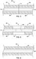
- FIG. 3is a cross-sectional view of a portion of another example pressure sensing guidewire
- FIG. 4is an enlarged view of a portion of FIG. 3 ;
- FIG. 5is a cross-sectional view of a portion of another example pressure sensing guidewire.
- references in the specification to “an embodiment”, “some embodiments”, “other embodiments”, etc.indicate that the embodiment described may include a particular feature, structure, or characteristic, but every embodiment may not necessarily include the particular feature, structure, or characteristic. Moreover, such phrases do not necessarily refer to the same embodiment. Further, when a particular feature, structure, or characteristic is described in connection with one embodiment, it should be understood that such feature, structure, or characteristic may also be used in connection with other embodiments, whether or not explicitly described, unless cleared stated to the contrary.
- some medical devicesmay include pressure sensors that allow a clinician to monitor blood pressure. Such devices may be useful in determining fractional flow reserve (FFR), which may be understood as the pressure after a stenosis relative to the pressure before the stenosis.
- FFRfractional flow reserve
- a number of pressure sensing devicesmay pose technical challenges for steering, tracking, torqueing or otherwise navigating the device within the vasculature.
- medical devicesmay include a relatively stiff pressure sensor located at or near the distal tip of the device and/or a sensor housing (in which the sensor is mounted) that may also be relatively stiff. Disclosed herein are a number of medical device that include pressure sensing capabilities and may be more easily steered, tracked, torqued, and/or otherwise navigated through the anatomy.
- FIG. 1is a schematic view of an example system 10 for obtaining pressure measurements within a patient's anatomy.
- the system 10includes a pressure sensing guidewire 12 having a guidewire shaft 14 that extends from a distal region 16 to a proximal region 18 .
- the pressure sensing guidewire 12may be configured to be attached to a connector or handle member 20 .
- Handle 20may include a suitable connector for a cable 22 to be attached to handle 20 and extend to another suitable device such as an interferometer or signal conditioner 24 .
- Signal conditioner 24may include a light source and may be configured to process optical signals received at signal conditioner 24 .
- Another cable 26may, in some embodiments, extend from signal conditioner 24 to a suitable output device such as a display device 28 , which may be configured to display information provided by signal conditioner 24 .
- Display device 28may represent the ratio textually, graphically, or pictorially for diagnosing a medical condition within the body lumen.
- a clinicianmay utilize the readings from display device 28 to tailor the intervention to the needs of the patient or otherwise advance the goals of the intervention. These are just examples. It will be appreciated that other devices and/or arrangements may be utilized with pressure sensing guidewire 12 .
- Distal region 16 of pressure sensing guidewire 12includes structure that facilitates use of pressure sensing guidewire 12 .
- Guidewire shaft 14includes a first tubular member 30 .
- first tubular member 30extends a substantial length of the pressure sensing guidewire 12 .
- First tubular member 30terminates at a tubular member distal end 32 .
- Distal region 16includes a coil structure 34 that extends distally to a coil structure distal end 36 .
- a distal cap 38abuts the coil structure distal end 36 and completes the distal portion of pressure sensing guidewire 12 .
- Distal cap 38defines a void space 40 .
- One or more apertures 42extend through a wall forming distal cap 38 , thereby providing fluid communication between void space 40 and the environment immediately outside of pressure sensing guidewire 12 .
- a pressure sensor 44is disposed within the void space 40 .
- the pressure sensor 44is configured to obtain pressure measurements within the environment immediately outside of pressure sensing guidewire 12 .
- pressure sensor 44is shown schematically in FIG. 1 , it can be appreciated that the structural form and/or type of pressure sensor 44 may vary.
- pressure sensor 44may include a semiconductor (e.g., silicon wafer) pressure sensor, piezoelectric pressure sensor, a fiber optic or optical pressure sensor, a Fabry-Perot type pressure sensor, an ultrasound transducer and/or ultrasound pressure sensor, a magnetic pressure sensor, a solid-state pressure sensor, or the like, or any other suitable pressure sensor.
- a clinicianmay use pressure sensing guidewire 12 to measure or calculate FFR (e.g., the pressure after an intravascular lesion relative to the pressure before the lesion). This may include taking an initial pressure reading before or upstream of the lesion and then a comparative reading after or downstream of the lesion. This may also include monitoring the pressure while advancing pressure sensing guidewire 12 through a blood vessel until a pressure differential or drop in pressure is observed, indicating that pressure sensing guidewire 12 has reached and/or partially past the lesion as well as monitoring increases in pressure during and/or following a treatment intervention.
- a second pressure measuring devicemay be used to measure pressure at another intravascular location and this pressure may be utilized in the calculation of FFR or otherwise used as part of the intervention.
- a fiber optic cable 46is operably connected to pressure sensor 44 and extends proximally therefrom.
- fiber optic cable 46is a polymer fiber optic cable and may extend a length of guidewire shaft 14 .
- fiber optic cable 46may include a distal section that is polymeric fiber optic cable and a proximal section that is glass fiber optic cable.
- fiber optic cable 46may be a glass fiber optic cable over substantially all of its length.
- at least a portion of fiber optic cable 46may include optionally include a protective coating 48 extending a length of fiber optic cable 46 .
- pressure sensing guidewire 12may include a second tubular member 50 .
- Second tubular member 50may be joined to distal cap 38 via a connection schematically illustrated as connection 52 .
- Connection 52may represent adhesive, solder, a weld, or any other suitable connection mechanism.
- the second tubular member 50forms part of the distal region 16 and in some embodiments may, in combination with the coil structure 34 , contribute to a shapeability of the distal region 16 .
- the distal region 16may be bent into a desired shape prior to being advanced through the vasculature.
- second tubular member 50includes several slots 54 . While three slots 54 are illustrated, it will be appreciated that second tubular member 50 may include any number of slots 54 .
- the relative size, number and spacing of slots 54 along second tubular member 50may be varied in order to achieve a desired level of flexibility and shapeability.
- FIG. 2provides a schematic illustration of a distal region 116 of a pressure sensing guidewire 112 .
- Pressure sensing guidewire 112includes a guidewire shaft 114 that includes a first tubular member 130 .
- first tubular member 130extends a substantial length of the pressure sensing guidewire 112 .
- First tubular member 130extends distally to a point 132 .
- a polymer sleeve 133extends distally from point 132 to a distal end 136 .
- a distal cap 138abuts the polymer sleeve 133 and completes the distal portion of pressure sensing guidewire 12 .
- Distal cap 138defines a void space 140 .
- One or more apertures 142extend through a wall forming distal cap 138 , thereby providing fluid communication between void space 140 and the environment immediately outside of pressure sensing guidewire 112 .
- a pressure sensor 144is disposed within the void space 140 and can be any suitable pressure sensor. By virtue of the aforementioned fluid communication afforded by the one or more apertures 142 , the pressure sensor 144 is configured to obtain pressure measurements within the environment immediately outside of pressure sensing guidewire 112 .
- a fiber optic cable 146is operably connected to pressure sensor 144 and extends proximally therefrom.
- fiber optic cable 146is a polymer fiber optic cable and may extend a length of guidewire shaft 114 .
- fiber optic cable 146may include a distal section that is polymeric fiber optic cable and a proximal section that is glass fiber optic cable.
- at least a portion of fiber optic cable 146may include optionally include a protective coating 148 extending a length of fiber optic cable 146 .
- pressure sensing guidewire 112may include a second tubular member 150 .
- the second tubular member 150forms part of the distal region 116 and in some embodiments may contribute to a shapeability of the distal region 116 .
- the distal region 116may be bent into a desired shape prior to being advanced through the vasculature.
- second tubular member 150includes several slots 154 . While three slots 154 are illustrated, it will be appreciated that second tubular member 150 may include any number of slots 154 . The relative size, number and spacing of slots 154 along second tubular member 150 may be varied in order to achieve a desired level of flexibility and shapeability.
- second tubular member 150secures and aligns the fiber optic cable 146 along a central axis of first tubular member 130 . In some embodiments, this central placement helps prevent pressure sensor 144 from contacting an internal surface of distal cap 138 . Contact, if it were to occur, could cause offsets in measured fluid pressure.
- pressure sensor 44may be located relatively closer to a distal end of pressure sensing guidewire 12 ( FIG. 1 ) and pressure sensing guidewire 112 ( FIG. 2 ) than previous pressure sensing guidewires that utilize glass fiber optic cables. Because polymeric fiber optic cables are more flexible than glass fiber optic cables, the fiber optic cable can, in the illustrated embodiments, extend through a flexible, shapeable distal region 16 , 116 . Accordingly, pressure sensor 44 , 144 may be located less than about 3 centimeters from a distal end of the pressure sensing guidewire 12 , 112 .
- pressure sensor 44 , 144may be located less than about 2 centimeters from a distal end of the pressure sensing guidewire 12 , 112 . In some embodiments, pressure sensor 44 , 144 may be located less than about 1 centimeter or less than about 0.5 centimeters from a distal end of the pressure sensing guidewire 12 , 112 .
- pressure sensor 44 , 144may be located at a relatively more proximal location.
- the pressure sensor 44 , 144may be disposed at a location that is as much as 30 centimeters from a distal end of pressure sensing guidewire 12 , 112 .
- the pressure sensor 44 , 144may be disposed at a location that is about 10 to 15 centimeters from a distal end of pressure sensing guidewire 12 , 112 .
- moving pressure sensor 44 , 144 to a relatively more proximal locationwill enable the distal portions of pressure sensing guidewire 12 , 112 to be made even more flexible, particularly in portions distal of pressure sensor 44 , 144 .
- fiber optic cable 46 , 146may function as an emergency tether, enabling retrieval of pressure sensing guidewire 12 , 112 .
- fiber optic cable 46 , 146may be a polymeric fiber optic cable that extends all the way or substantially all of the way through pressure sensing guidewire 12 , 112 .
- Thisprovides enhanced flexibility, but as polymeric fiber optic cables do not conduct light as well as glass fiber optics, light losses can be higher than would be achieved using a glass fiber optic cable. However, as long as the losses are repeatable, the losses can be overcome, for example, by increasing the intensity of light originating from a light source.
- fiber optic cable 46 , 146can include a distal portion that is polymeric and a proximal portion that is glass, thereby permitting greater flexibility and shapeability in the distal region 16 , 116 of pressure sensing guidewire 12 , 112 while reducing overall light losses.
- fiber optic cable 46 , 146may be glass fiber optic cable that extends all the way or substantially all of the way through pressure sensing guidewire 12 , 112 .
- FIG. 3schematically illustrates a portion of a guidewire 60 that includes a distal portion 62 and a proximal portion 64 .
- distal portion 62 and proximal portion 64have a constant cross-sectional profile.
- Distal portion 62includes a guidewire shaft 66 while proximal portion 64 includes a guidewire shaft 68 .
- a distal fiber optic cable 70extends through distal portion 62 and a proximal fiber optic cable 72 extends through proximal portion 64 .
- Distal portion 62meets proximal portion 64 at a connector 74 .
- distal fiber optic cable 70is a polymeric fiber optic cable while proximal fiber optic cable 72 is a glass fiber optic cable.
- connector 74generally represents a connection between distal portion 62 and proximal portion 64 .
- connector 74may represent a simple butt joint between distal portion 62 and proximal portion 64 , perhaps including a suitable adhesive.
- connector 74schematically represents a connector assembly, as illustrated in FIG. 4 .
- FIG. 4represents an enlarged view of FIG. 3 , showing connector 74 manifested as a connector assembly 76 .
- connector assembly 76includes an outer portion 78 that is configured to join guidewire shaft 66 and guidewire shaft 68 .
- guidewire shaft 66 and guidewire shaft 68may extend partially into outer portion 78 and may be adhesively or frictionally secured therein.
- Connector assembly 76includes a fiber optic segment 80 that is configured to optically couple to A distal fiber optic cable 70 and to proximal fiber optic cable 72 .
- Connector 76may be configured to releasably secure guidewire shaft 66 and guidewire shaft 68 together.
- connector 76may be configured to provide what is intended to be a permanent connection, i.e., for the useable life of guidewire shaft 60 .
- FIG. 5schematically illustrates a portion of a guidewire 82 .
- Guidewire 82includes an outer guidewire shaft portion 84 and a fiber optic cable 86 extending through outer guidewire shaft portion 84 .
- fiber optic cable 86is a polymeric fiber optic cable.
- the polymeric fiber optic cableextends essentially a length of the guidewire 82 .
- pressure sensing guidewire 12 , 112may be advanced through a patient's vasculature. In some embodiments, pressure sensing guidewire 12 , 112 may be advanced into the vasculature via a catheter (not shown). In some embodiments, distal region 16 , 116 may be shaped prior to insertion. Pressure sensing guidewire 12 , 112 may be advanced such that the distal end of pressure sensing guidewire 12 , 112 may be positioned proximate to a lesion. Once positioned, signal conditioner 24 may be activated to generate optical signals from a light source.
- the generated optical signalsare guided through the polymer fiber optic cable 46 , 146 to pressure sensor 44 , 144 for measuring pressure of fluids proximal the lesion within the vasculature.
- pressure sensing guidewire 12 , 112may be advanced through the lesion such that pressure sensor 44 , 144 is distal to the lesion and another pressure measurement may be taken.
- the signal conditioner 24may be operated to send the optical signals to the pressure sensor 44 , 144 and receive the optical signals reflected by the pressure sensor 44 , 144 for measuring pressure of fluids based on the optical signals within the vasculature.
- a ratio of the fluid pressure measured proximal to the lesion and the fluid pressure distal to the lesionmay be determined by signal conditioner 24 and displayed on display device 28 for determining the pressure gradient about the lesion within the vasculature.
- the determined pressure gradientmay be used for diagnosing a medical condition with the vasculature.
- pressure sensing guidewire 12 , 112may be withdrawn prior to measuring the fluid pressure either distal or again proximal to the lesion from the vasculature.
- tubular member 34 , 133may be a polymer or metallic sleeve made from a suitable polymeric material or a metal.
- the polymeric materialmay include, but not limited to, polytetrafluoroethylene (PTFE), ethylene tetrafluoroethylene (ETFE), fluorinated ethylene propylene (FEP), polyoxymethylene (POM, for example, DELRIN® available from DuPont), polyether block ester, polyurethane (for example, Polyurethane 85A), polypropylene (PP), polyvinylchloride (PVC), polyether-ester (for example, ARNITEL® available from DSM Engineering Plastics), ether or ester based copolymers (for example, butylene/poly(alkylene ether) phthalate and/or other polyester elastomers such as HYTREL® available from DuPont), polyamide (for example, DURETHAN® available from Bayer or CRISTAMID® available from Elf Ato
- tubular member 34 , 133may include a radiopaque material.
- tubular member 34 , 133may be made from a polymer loaded with the radiopaque material for tracking the guidewire 102 within the body lumen.
- tubular member 34 , 133 or one or more discrete portions thereofmay include about 50-95 wt-% or about 75-95 wt-% radiopaque material with the balance being polymeric.
- the radiopaque materialmay include tungsten. Other materials and/or arrangements may also be used.
- the pressure sensing guidewire 12 , 112may be manufactured without having additional radiopaque marker bands or radiopaque marker coils coupled thereto, for example, at a distal end of the pressure sensing guidewire 12 , 112 .
- tubular member 34 , 133may include such radiopaque structures.
- Second tubular member 50 , 150 and/or distal cap 38 , 128may be made from a metal, metal alloy, polymer (some examples of which are disclosed above), a metal-polymer composite, ceramics, combinations thereof, and the like, or other suitable material.
- suitable metals and metal alloysinclude stainless steel, such as 304V, 304L, and 316LV stainless steel; mild steel; nickel-titanium alloy such as linear-elastic and/or super-elastic nitinol; other nickel alloys such as nickel-chromium-molybdenum alloys (e.g., UNS: N06625 such as INCONEL® 625, UNS: N06022 such as HASTELLOY® C-22®, UNS: N10276 such as HASTELLOY® C276®, other HASTELLOY® alloys, and the like), nickel-copper alloys (e.g., UNS: N04400 such as MONEL® 400, NICKELVAC® 400, NICORROS® 400, and the like), nickel-cobalt-chromium-molybdenum alloys (e.g., UNS: R30035 such as MP35-N® and the like), nickel-molybdenum alloys (e.g.,
- linear elastic and/or non-super-elastic nitinolmay be distinguished from super elastic nitinol in that the linear elastic and/or non-super-elastic nitinol does not display a substantial “superelastic plateau” or “flag region” in its stress/strain curve like super elastic nitinol does.
- linear elastic and/or non-super-elastic nitinolas recoverable strain increases, the stress continues to increase in a substantially linear, or a somewhat, but not necessarily entirely linear relationship until plastic deformation begins or at least in a relationship that is more linear that the super elastic plateau and/or flag region that may be seen with super elastic nitinol.
- linear elastic and/or non-super-elastic nitinolmay also be termed “substantially” linear elastic and/or non-super-elastic nitinol.
- linear elastic and/or non-super-elastic nitinolmay also be distinguishable from super elastic nitinol in that linear elastic and/or non-super-elastic nitinol may accept up to about 2-5% strain while remaining substantially elastic (e.g., before plastically deforming) whereas super elastic nitinol may accept up to about 8% strain before plastically deforming. Both of these materials can be distinguished from other linear elastic materials such as stainless steel (that can also can be distinguished based on its composition), which may accept only about 0.2 to 0.44 percent strain before plastically deforming.
- the linear elastic and/or non-super-elastic nickel-titanium alloyis an alloy that does not show any martensite/austenite phase changes that are detectable by differential scanning calorimetry (DSC) and dynamic metal thermal analysis (DMTA) analysis over a large temperature range.
- DSCdifferential scanning calorimetry
- DMTAdynamic metal thermal analysis
- the mechanical bending properties of such materialmay therefore be generally inert to the effect of temperature over this very broad range of temperature.
- the mechanical bending properties of the linear elastic and/or non-super-elastic nickel-titanium alloy at ambient or room temperatureare substantially the same as the mechanical properties at body temperature, for example, in that they do not display a super-elastic plateau and/or flag region.
- the linear elastic and/or non-super-elastic nickel-titanium alloymaintains its linear elastic and/or non-super-elastic characteristics and/or properties.
- the linear elastic and/or non-super-elastic nickel-titanium alloymay be in the range of about 50 to about 60 weight percent nickel, with the remainder being essentially titanium. In some embodiments, the composition is in the range of about 54 to about 57 weight percent nickel.
- a suitable nickel-titanium alloyis FHP-NT alloy commercially available from Furukawa Techno Material Co. of Kanagawa, Japan. Some examples of nickel titanium alloys are disclosed in U.S. Pat. Nos. 5,238,004 and 6,508,803, which are incorporated herein by reference. Other suitable materials may include ULTANIUMTM (available from Neo-Metrics) and GUM METALTM (available from Toyota).
- a superelastic alloyfor example a superelastic nitinol can be used to achieve desired properties.
- portions or all of second tubular member 50 , 150 and/or distal cap 38 , 128may also be doped with, made of, or otherwise include a radiopaque material.
- Radiopaque materialsare understood to be materials capable of producing a relatively bright image on a fluoroscopy screen or another imaging technique during a medical procedure. This relatively bright image aids the user of pressure sensing guidewire 12 , 112 in determining its location.
- Some examples of radiopaque materialscan include, but are not limited to, gold, platinum, palladium, tantalum, tungsten alloy, polymer material loaded with a radiopaque filler, and the like. Additionally, other radiopaque marker bands and/or coils may also be incorporated to achieve the same result.
- a degree of Magnetic Resonance Imaging (MRI) compatibilityis imparted into pressure sensing guidewire 12 , 112 .
- pressure sensing guidewire 12 , 112 or portions thereofmay be made of a material that does not substantially distort the image and create substantial artifacts (i.e., gaps in the image). Certain ferromagnetic materials, for example, may not be suitable because they may create artifacts in an MRI image.
- Pressure sensing guidewire 12 , 112 , or portions thereofmay also be made from a material that the MRI machine can image.
- Some materials that exhibit these characteristicsinclude, for example, tungsten, cobalt-chromium-molybdenum alloys (e.g., UNS: R30003 such as ELGILOY®, PHYNOX®, and the like), nickel-cobalt-chromium-molybdenum alloys (e.g., UNS: R30035 such as MP35-N® and the like), nitinol, and the like, and others.
- cobalt-chromium-molybdenum alloyse.g., UNS: R30003 such as ELGILOY®, PHYNOX®, and the like
- nickel-cobalt-chromium-molybdenum alloyse.g., UNS: R30035 such as MP35-N® and the like
- nitinoland the like, and others.
Landscapes
- Health & Medical Sciences (AREA)
- Life Sciences & Earth Sciences (AREA)
- Heart & Thoracic Surgery (AREA)
- Animal Behavior & Ethology (AREA)
- Veterinary Medicine (AREA)
- Public Health (AREA)
- Biophysics (AREA)
- General Health & Medical Sciences (AREA)
- Engineering & Computer Science (AREA)
- Biomedical Technology (AREA)
- Pathology (AREA)
- Medical Informatics (AREA)
- Molecular Biology (AREA)
- Surgery (AREA)
- Physics & Mathematics (AREA)
- Cardiology (AREA)
- Physiology (AREA)
- Vascular Medicine (AREA)
- Pulmonology (AREA)
- Anesthesiology (AREA)
- Hematology (AREA)
- Measuring Pulse, Heart Rate, Blood Pressure Or Blood Flow (AREA)
Abstract
Description
This application claims priority under 35 U.S.C. § 119 to U.S. Provisional Application Ser. No. 61/955,089, filed Mar. 18, 2014, the entirety of which is incorporated herein by reference.
The present disclosure pertains to medical devices, and methods for using and manufacturing medical devices. More particularly, the present disclosure pertains to medical devices and methods that relate to pressure sensing guidewires.
A wide variety of intracorporeal medical devices have been developed for medical use, for example, intravascular use. Some of these devices include guidewires, catheters, and the like. These devices are manufactured by any one of a variety of different manufacturing methods and may be used according to any one of a variety of methods. Of the known medical devices and methods, each has certain advantages and disadvantages. There is an ongoing need to provide alternative medical devices as well as alternative methods for manufacturing and using medical devices.
This disclosure provides design, material, manufacturing method, and use alternatives for medical devices. An example pressure sensing guidewire is disclosed. The pressure sensing guidewire has a distal end and a proximal end and comprises:
a tubular member having a distal portion and a proximal portion;
an optical pressure sensor disposed within the distal portion of the tubular member; and
a polymer fiber optic cable extending proximally from the optical pressure sensor.
Alternatively or additionally to any of the embodiments above, the polymer fiber optic cable extends proximally to a proximal end of the pressure sensing guidewire.
Alternatively or additionally to any of the embodiments above, the polymer fiber optic cable extends proximally and is operably connected to a glass fiber optic that extends proximally to a proximal end of the pressure sensing guidewire.
Alternatively or additionally to any of the embodiments above, the distal portion of the tubular member forms a distal cap, and the optical pressure sensor is disposed within the distal cap.
Alternatively or additionally to any of the embodiments above, the distal cap includes one or more apertures permitting blood to enter an interior of the distal cap.
Alternatively or additionally to any of the embodiments above, the distal portion of the tubular member includes a shapeable structure.
Alternatively or additionally to any of the embodiments above, the pressure sensing guidewire further comprises a tubular member with a plurality of slots formed therein extending proximally from the distal cap.
Alternatively or additionally to any of the embodiments above, the pressure sensing guidewire further comprises a coil disposed over at least a portion of the tubular member with a plurality of slots formed therein.
Alternatively or additionally to any of the embodiments above, the pressure sensing guidewire further comprises a polymer sleeve disposed over at least a portion of the tubular member with a plurality of slots formed therein.
A pressure sensing guidewire is disclosed. The pressure sensing guidewire has a distal end and a proximal end and comprises:
a first tubular member having a distal portion and a proximal portion;
a second tubular member extending distally from the distal portion of the first tubular member, the second tubular member having a proximal end, a distal end and a plurality of slots formed therein;
a distal cap extending distally from the distal end of the second tubular member;
an optical pressure sensor disposed within the distal cap; and
a polymer fiber optic cable extending proximally from the optical pressure sensor;
wherein the optical pressure sensor is located at a position that is less than about 3 centimeters from the distal end of the pressure sensing guidewire.
Alternatively or additionally to any of the embodiments above, the polymer fiber optic cable extends proximally to a proximal end of the pressure sensing guidewire.
Alternatively or additionally to any of the embodiments above, the polymer fiber optic cable extends proximally and is operably connected to a glass fiber optic that extends proximally to a proximal end of the pressure sensing guidewire.
Alternatively or additionally to any of the embodiments above, the distal cap includes one or more apertures permitting blood to enter an interior of the distal cap.
Alternatively or additionally to any of the embodiments above, the pressure sensing guidewire further comprises a coil disposed over at least a portion of the second tubular member.
Alternatively or additionally to any of the embodiments above, the pressure sensing guidewire further comprises a polymer sleeve disposed over at least a portion of the second tubular member.
A method of using a guidewire including a tubular member having a distal portion and a proximal portion, an optical pressure sensor disposed within the distal portion of the tubular member and a polymer fiber optic cable extending proximally from the optical pressure sensor is disclosed. The method comprises:
advancing the guidewire through a patient's vasculature to a position proximate a lesion; measuring a pressure proximal the lesion;
advancing the guidewire through the lesion such that the pressure sensor is distal the legion; and measuring a pressure distal the lesion.
Alternatively or additionally to any of the embodiments above, measuring a pressure proximal the lesion precedes advancing the guidewire through the lesion.
Alternatively or additionally to any of the embodiments above, the method further comprises, subsequent to advancing the guidewire through the lesion, withdrawing the guidewire prior to measuring a pressure proximal the legion.
Alternatively or additionally to any of the embodiments above, advancing the guidewire through the lesion comprises advancing the guidewire through the lesion such that a distal end of the guidewire extends past the lesion a distance of less than about 3 centimeters.
Alternatively or additionally to any of the embodiments above, the guidewire includes a shapeable distal portion, and the method further comprises shaping the shapeable distal portion prior to advancing the guidewire through a patient's vasculature to a position proximate a lesion.
The above summary of some embodiments is not intended to describe each disclosed embodiment or every implementation of the present invention. The Figures, and Detailed Description, which follow, more particularly exemplify these embodiments.
The present disclosure may be more completely understood in consideration of the following detailed description of various embodiments of the present disclosure in connection with the accompanying drawings, in which:
While the present disclosure is amenable to various modifications and alternative forms, specifics thereof have been shown by way of example in the drawings and will be described in detail. It should be understood, however, that the intention is not to limit the present disclosure to particular embodiments described. On the contrary, the intention is to cover all modifications, equivalents, and alternatives falling within the spirit and scope of the present disclosure.
Definitions of certain term are provided below, and these definitions shall be applied, unless a different definition is given in the claims or elsewhere in this specification.
All numeric values used herein are assumed to be modified by the term “about,” whether or not explicitly indicated. The term “about” generally refers to a range of numbers that one of skill in the art would consider equivalent to the recited value (i.e., having the same or substantially the same function or result). In many instances, the terms “about” may include numbers that are rounded to the nearest significant figure. The recitation of numerical ranges by endpoints includes all numbers within that range (e.g. 1 to 5 includes 1, 1.5, 2, 2.75, 3, 3.80, 4, and 5).
As used in this specification and the appended claims, the singular forms “a”, “an”, and “the” include plural referents, unless the content clearly dictates otherwise. As used in this specification and the appended claims, the term “or” is generally employed in its sense including “and/or”, unless the content clearly dictates otherwise.
The following detailed description should be read with reference to the drawings in which similar elements in different drawings are identified with the same reference numbers. The drawings, which are not necessarily to scale, depict illustrative embodiments and are not intended to limit the scope of the invention.
It is noted that references in the specification to “an embodiment”, “some embodiments”, “other embodiments”, etc., indicate that the embodiment described may include a particular feature, structure, or characteristic, but every embodiment may not necessarily include the particular feature, structure, or characteristic. Moreover, such phrases do not necessarily refer to the same embodiment. Further, when a particular feature, structure, or characteristic is described in connection with one embodiment, it should be understood that such feature, structure, or characteristic may also be used in connection with other embodiments, whether or not explicitly described, unless cleared stated to the contrary.
During some medical interventions, it may be desirable to measure and/or monitor the blood pressure within a blood vessel. For example, some medical devices may include pressure sensors that allow a clinician to monitor blood pressure. Such devices may be useful in determining fractional flow reserve (FFR), which may be understood as the pressure after a stenosis relative to the pressure before the stenosis. A number of pressure sensing devices, however, may pose technical challenges for steering, tracking, torqueing or otherwise navigating the device within the vasculature. For example, medical devices may include a relatively stiff pressure sensor located at or near the distal tip of the device and/or a sensor housing (in which the sensor is mounted) that may also be relatively stiff. Disclosed herein are a number of medical device that include pressure sensing capabilities and may be more easily steered, tracked, torqued, and/or otherwise navigated through the anatomy.
Apressure sensor 44 is disposed within thevoid space 40. By virtue of the aforementioned fluid communication afforded by the one ormore apertures 42, thepressure sensor 44 is configured to obtain pressure measurements within the environment immediately outside ofpressure sensing guidewire 12. Whilepressure sensor 44 is shown schematically inFIG. 1 , it can be appreciated that the structural form and/or type ofpressure sensor 44 may vary. For example,pressure sensor 44 may include a semiconductor (e.g., silicon wafer) pressure sensor, piezoelectric pressure sensor, a fiber optic or optical pressure sensor, a Fabry-Perot type pressure sensor, an ultrasound transducer and/or ultrasound pressure sensor, a magnetic pressure sensor, a solid-state pressure sensor, or the like, or any other suitable pressure sensor.
A clinician may use pressure sensing guidewire12 to measure or calculate FFR (e.g., the pressure after an intravascular lesion relative to the pressure before the lesion). This may include taking an initial pressure reading before or upstream of the lesion and then a comparative reading after or downstream of the lesion. This may also include monitoring the pressure while advancingpressure sensing guidewire 12 through a blood vessel until a pressure differential or drop in pressure is observed, indicating thatpressure sensing guidewire 12 has reached and/or partially past the lesion as well as monitoring increases in pressure during and/or following a treatment intervention. In some embodiments, a second pressure measuring device may be used to measure pressure at another intravascular location and this pressure may be utilized in the calculation of FFR or otherwise used as part of the intervention.
Afiber optic cable 46 is operably connected to pressuresensor 44 and extends proximally therefrom. In some embodiments,fiber optic cable 46 is a polymer fiber optic cable and may extend a length ofguidewire shaft 14. In some embodiments, as will be discussed with respect to subsequent drawings,fiber optic cable 46 may include a distal section that is polymeric fiber optic cable and a proximal section that is glass fiber optic cable. In some embodiments, it is contemplated thatfiber optic cable 46 may be a glass fiber optic cable over substantially all of its length. In some embodiments, at least a portion offiber optic cable 46 may include optionally include aprotective coating 48 extending a length offiber optic cable 46.
In some embodiments, as illustrated,pressure sensing guidewire 12 may include a secondtubular member 50. Secondtubular member 50 may be joined todistal cap 38 via a connection schematically illustrated as connection52. Connection52 may represent adhesive, solder, a weld, or any other suitable connection mechanism. The secondtubular member 50 forms part of thedistal region 16 and in some embodiments may, in combination with the coil structure34, contribute to a shapeability of thedistal region 16. In some embodiments, thedistal region 16 may be bent into a desired shape prior to being advanced through the vasculature. To aid in flexibility, in some embodiments secondtubular member 50 includesseveral slots 54. While threeslots 54 are illustrated, it will be appreciated that secondtubular member 50 may include any number ofslots 54. The relative size, number and spacing ofslots 54 along secondtubular member 50 may be varied in order to achieve a desired level of flexibility and shapeability.
Apressure sensor 144 is disposed within thevoid space 140 and can be any suitable pressure sensor. By virtue of the aforementioned fluid communication afforded by the one ormore apertures 142, thepressure sensor 144 is configured to obtain pressure measurements within the environment immediately outside ofpressure sensing guidewire 112.
Afiber optic cable 146 is operably connected to pressuresensor 144 and extends proximally therefrom. In some embodiments,fiber optic cable 146 is a polymer fiber optic cable and may extend a length ofguidewire shaft 114. In some embodiments, as will be discussed with respect to subsequent drawings,fiber optic cable 146 may include a distal section that is polymeric fiber optic cable and a proximal section that is glass fiber optic cable. In some embodiments, at least a portion offiber optic cable 146 may include optionally include aprotective coating 148 extending a length offiber optic cable 146.
In some embodiments, as illustrated,pressure sensing guidewire 112 may include a secondtubular member 150. The secondtubular member 150 forms part of thedistal region 116 and in some embodiments may contribute to a shapeability of thedistal region 116. In some embodiments, thedistal region 116 may be bent into a desired shape prior to being advanced through the vasculature. To aid in flexibility, in some embodiments secondtubular member 150 includesseveral slots 154. While threeslots 154 are illustrated, it will be appreciated that secondtubular member 150 may include any number ofslots 154. The relative size, number and spacing ofslots 154 along secondtubular member 150 may be varied in order to achieve a desired level of flexibility and shapeability.
In some embodiments, secondtubular member 150 secures and aligns thefiber optic cable 146 along a central axis of firsttubular member 130. In some embodiments, this central placement helps preventpressure sensor 144 from contacting an internal surface ofdistal cap 138. Contact, if it were to occur, could cause offsets in measured fluid pressure.
As illustrated inFIGS. 1 and 2 , pressure sensor44 (FIG. 1 ) and pressure sensor144 (FIG. 2 ) may be located relatively closer to a distal end of pressure sensing guidewire12 (FIG. 1 ) and pressure sensing guidewire112 (FIG. 2 ) than previous pressure sensing guidewires that utilize glass fiber optic cables. Because polymeric fiber optic cables are more flexible than glass fiber optic cables, the fiber optic cable can, in the illustrated embodiments, extend through a flexible, shapeabledistal region pressure sensor pressure sensing guidewire pressure sensor pressure sensing guidewire pressure sensor pressure sensing guidewire
Alternatively, and in some embodiments,pressure sensor pressure sensor pressure sensing guidewire pressure sensor pressure sensing guidewire pressure sensor pressure sensing guidewire pressure sensor fiber optic cable pressure sensing guidewire
As noted above, in some embodimentsfiber optic cable pressure sensing guidewire fiber optic cable distal region pressure sensing guidewire fiber optic cable pressure sensing guidewire
As schematically illustrated,connector 74 generally represents a connection betweendistal portion 62 andproximal portion 64. In some embodiments,connector 74 may represent a simple butt joint betweendistal portion 62 andproximal portion 64, perhaps including a suitable adhesive. In some embodiments, however,connector 74 schematically represents a connector assembly, as illustrated inFIG. 4 .
During operation,pressure sensing guidewire pressure sensing guidewire distal region Pressure sensing guidewire pressure sensing guidewire signal conditioner 24 may be activated to generate optical signals from a light source. The generated optical signals are guided through the polymerfiber optic cable pressure sensor pressure sensing guidewire pressure sensor signal conditioner 24 may be operated to send the optical signals to thepressure sensor pressure sensor
A ratio of the fluid pressure measured proximal to the lesion and the fluid pressure distal to the lesion may be determined bysignal conditioner 24 and displayed ondisplay device 28 for determining the pressure gradient about the lesion within the vasculature. The determined pressure gradient may be used for diagnosing a medical condition with the vasculature. Once at least one of the fluid pressure proximal to the lesion, the fluid pressure distal to the lesion and the pressure gradient about the lesion within the vasculature are determined,pressure sensing guidewire pressure sensing guidewire pressure sensing guidewire
In some embodiments,tubular member 34,133 may be a polymer or metallic sleeve made from a suitable polymeric material or a metal. Examples of the polymeric material may include, but not limited to, polytetrafluoroethylene (PTFE), ethylene tetrafluoroethylene (ETFE), fluorinated ethylene propylene (FEP), polyoxymethylene (POM, for example, DELRIN® available from DuPont), polyether block ester, polyurethane (for example, Polyurethane 85A), polypropylene (PP), polyvinylchloride (PVC), polyether-ester (for example, ARNITEL® available from DSM Engineering Plastics), ether or ester based copolymers (for example, butylene/poly(alkylene ether) phthalate and/or other polyester elastomers such as HYTREL® available from DuPont), polyamide (for example, DURETHAN® available from Bayer or CRISTAMID® available from Elf Atochem), elastomeric polyamides, block polyamide/ethers, polyether block amide (PEBA, for example available under the trade name PEBAX®), ethylene vinyl acetate copolymers (EVA), silicones, polyethylene (PE), Marlex high-density polyethylene, Marlex low-density polyethylene, linear low density polyethylene (for example REXELL®), polyester, polybutylene terephthalate (PBT), polyethylene terephthalate (PET), polytrimethylene terephthalate, polyethylene naphthalate (PEN), polyetheretherketone (PEEK), polyimide (PI), polyetherimide (PEI), polyphenylene sulfide (PPS), polyphenylene oxide (PPO), poly paraphenylene terephthalamide (for example, KEVLAR®), polysulfone, nylon, nylon-12 (such as GRILAMID® available from EMS American Grilon), perfluoro(propyl vinyl ether) (PFA), ethylene vinyl alcohol, polyolefin, polystyrene, epoxy, polyvinylidene chloride (PVdC), poly(styrene-£-isobutylene-£-styrene) (for example, SIBS and/or SIBS 50A), polycarbonates, ionomers, biocompatible polymers, other suitable materials, or mixtures, combinations, copolymers thereof, polymer/metal composites, and the like. In some embodiments, t firsttubular member
In some of these as well as other embodiments,tubular member 34,133 may include a radiopaque material. In other words,tubular member 34,133 may be made from a polymer loaded with the radiopaque material for tracking the guidewire102 within the body lumen. For example,tubular member 34,133 or one or more discrete portions thereof may include about 50-95 wt-% or about 75-95 wt-% radiopaque material with the balance being polymeric. In some embodiments, the radiopaque material may include tungsten. Other materials and/or arrangements may also be used. By virtue of including a radiopaque material intubular member 34,133, thepressure sensing guidewire pressure sensing guidewire tubular member 34,133 may include such radiopaque structures.
Secondtubular member distal cap 38,128 may be made from a metal, metal alloy, polymer (some examples of which are disclosed above), a metal-polymer composite, ceramics, combinations thereof, and the like, or other suitable material. Some examples of suitable metals and metal alloys include stainless steel, such as 304V, 304L, and 316LV stainless steel; mild steel; nickel-titanium alloy such as linear-elastic and/or super-elastic nitinol; other nickel alloys such as nickel-chromium-molybdenum alloys (e.g., UNS: N06625 such as INCONEL® 625, UNS: N06022 such as HASTELLOY® C-22®, UNS: N10276 such as HASTELLOY® C276®, other HASTELLOY® alloys, and the like), nickel-copper alloys (e.g., UNS: N04400 such as MONEL® 400, NICKELVAC® 400, NICORROS® 400, and the like), nickel-cobalt-chromium-molybdenum alloys (e.g., UNS: R30035 such as MP35-N® and the like), nickel-molybdenum alloys (e.g., UNS: N10665 such as HASTELLOY® ALLOY B2®), other nickel-chromium alloys, other nickel-molybdenum alloys, other nickel-cobalt alloys, other nickel-iron alloys, other nickel-copper alloys, other nickel-tungsten or tungsten alloys, and the like; cobalt-chromium alloys; cobalt-chromium-molybdenum alloys (e.g., UNS: R30003 such as ELGILOY®, PHYNOX®, and the like); nickel-cobalt-chromium-molybdenum alloys (e.g., UNS: R30035 such as MP35-N® and the like), platinum enriched stainless steel; titanium; combinations thereof; and the like; or any other suitable material.
As alluded to herein, within the family of commercially available nickel-titanium or nitinol alloys, is a category designated “linear elastic” or “non-super-elastic” which, although may be similar in chemistry to conventional shape memory and super elastic varieties, may exhibit distinct and useful mechanical properties. Linear elastic and/or non-super-elastic nitinol may be distinguished from super elastic nitinol in that the linear elastic and/or non-super-elastic nitinol does not display a substantial “superelastic plateau” or “flag region” in its stress/strain curve like super elastic nitinol does. Instead, in the linear elastic and/or non-super-elastic nitinol, as recoverable strain increases, the stress continues to increase in a substantially linear, or a somewhat, but not necessarily entirely linear relationship until plastic deformation begins or at least in a relationship that is more linear that the super elastic plateau and/or flag region that may be seen with super elastic nitinol. Thus, for the purposes of this disclosure linear elastic and/or non-super-elastic nitinol may also be termed “substantially” linear elastic and/or non-super-elastic nitinol.
In some cases, linear elastic and/or non-super-elastic nitinol may also be distinguishable from super elastic nitinol in that linear elastic and/or non-super-elastic nitinol may accept up to about 2-5% strain while remaining substantially elastic (e.g., before plastically deforming) whereas super elastic nitinol may accept up to about 8% strain before plastically deforming. Both of these materials can be distinguished from other linear elastic materials such as stainless steel (that can also can be distinguished based on its composition), which may accept only about 0.2 to 0.44 percent strain before plastically deforming.
In some embodiments, the linear elastic and/or non-super-elastic nickel-titanium alloy is an alloy that does not show any martensite/austenite phase changes that are detectable by differential scanning calorimetry (DSC) and dynamic metal thermal analysis (DMTA) analysis over a large temperature range. For example, in some embodiments, there may be no martensite/austenite phase changes detectable by DSC and DMTA analysis in the range of about −60 degrees Celsius (° C.) to about 120° C. in the linear elastic and/or non-super-elastic nickel-titanium alloy. The mechanical bending properties of such material may therefore be generally inert to the effect of temperature over this very broad range of temperature. In some embodiments, the mechanical bending properties of the linear elastic and/or non-super-elastic nickel-titanium alloy at ambient or room temperature are substantially the same as the mechanical properties at body temperature, for example, in that they do not display a super-elastic plateau and/or flag region. In other words, across a broad temperature range, the linear elastic and/or non-super-elastic nickel-titanium alloy maintains its linear elastic and/or non-super-elastic characteristics and/or properties.
In some embodiments, the linear elastic and/or non-super-elastic nickel-titanium alloy may be in the range of about 50 to about 60 weight percent nickel, with the remainder being essentially titanium. In some embodiments, the composition is in the range of about 54 to about 57 weight percent nickel. One example of a suitable nickel-titanium alloy is FHP-NT alloy commercially available from Furukawa Techno Material Co. of Kanagawa, Japan. Some examples of nickel titanium alloys are disclosed in U.S. Pat. Nos. 5,238,004 and 6,508,803, which are incorporated herein by reference. Other suitable materials may include ULTANIUM™ (available from Neo-Metrics) and GUM METAL™ (available from Toyota). In some other embodiments, a superelastic alloy, for example a superelastic nitinol can be used to achieve desired properties.
In at least some embodiments, portions or all of secondtubular member distal cap 38,128 may also be doped with, made of, or otherwise include a radiopaque material. Radiopaque materials are understood to be materials capable of producing a relatively bright image on a fluoroscopy screen or another imaging technique during a medical procedure. This relatively bright image aids the user ofpressure sensing guidewire
In some embodiments, a degree of Magnetic Resonance Imaging (MRI) compatibility is imparted intopressure sensing guidewire pressure sensing guidewire Pressure sensing guidewire
Other embodiments of the present disclosure will be apparent to those skilled in the art from consideration of the specification and practice of the embodiments disclosed herein. It is intended that the specification and examples be considered as exemplary only, and departure in form and detail may be made without departing from the scope and spirit of the present disclosure as described in the following claims.
Claims (19)
1. A pressure sensing guidewire having a distal end and a proximal end, the pressure sensing guidewire comprising:
a first tubular member having a distal portion and a proximal portion, the distal portion forming a distal cap having an inner surface;
a second tubular member disposed within the first tubular member, the second tubular member having a constant diameter over its length and comprising a plurality of flexibility-enhancing slots formed therein;
an optical pressure sensor disposed within the distal cap, wherein the optical pressure sensor includes a Fabry-Perot pressure sensor; and
a polymer fiber optic cable extending proximally from the optical pressure sensor and through the second tubular member, the optical pressure sensor disposed at a distal end of the polymer fiber optic cable;
wherein the second tubular member limits radial movement of the polymer fiber optic cable relative to the first tubular member and thus protects the optical pressure sensor from contacting the inner surface of the distal cap when the pressure sensing guidewire is subjected to bending.
2. The pressure sensing guidewire ofclaim 1 , wherein the polymer fiber optic cable extends proximally to a proximal end of the pressure sensing guidewire.
3. The pressure sensing guidewire ofclaim 1 , wherein the polymer fiber optic cable extends proximally and is operably connected to a glass fiber optic that extends proximally to a proximal end of the pressure sensing guidewire.
4. The pressure sensing guidewire ofclaim 1 , wherein the distal cap includes one or more apertures permitting blood to enter an interior of the distal cap.
5. The pressure sensing guidewire ofclaim 1 , wherein the distal portion of the tubular member includes a shapeable structure.
6. The pressure sensing guidewire ofclaim 1 , wherein the second tubular member extends proximally from the distal cap.
7. The pressure sensing guidewire ofclaim 6 , further comprising a coil disposed over at least a portion of the second tubular member.
8. The pressure sensing guidewire ofclaim 6 , further comprising a polymer sleeve disposed over at least a portion of the second tubular member.
9. A pressure sensing guidewire having a distal end and a proximal end, the pressure sensing guidewire comprising:
a first tubular member having a distal portion and a proximal portion;
a constant diameter cylindrical second tubular member extending distally from the distal portion of the first tubular member, the second tubular member having a proximal end, a distal end and a plurality of slots formed therein;
a distal cap extending distally from the distal end of the second tubular member;
an optical pressure sensor disposed within the distal cap, wherein the optical pressure sensor includes a Fabry-Perot pressure sensor; and
a polymer fiber optic cable extending proximally from the optical pressure sensor;
wherein the optical pressure sensor is disposed within the distal cap at a position that is less than 3 centimeters from the distal end of the pressure sensing guidewire, and wherein the optical pressure sensor is constrained from contacting the distal cap by the second tubular member constraining radial movement of the polymer fiber optic cable relative to the first tubular member.
10. The pressure sensing guidewire ofclaim 9 , wherein the polymer fiber optic cable extends proximally to a proximal end of the pressure sensing guidewire.
11. The pressure sensing guidewire ofclaim 9 , wherein the polymer fiber optic cable extends proximally and is operably connected to a glass fiber optic that extends proximally to a proximal end of the pressure sensing guidewire.
12. The pressure sensing guidewire ofclaim 9 , wherein the distal cap includes one or more apertures permitting blood to enter an interior of the distal cap.
13. The pressure sensing guidewire ofclaim 9 , further comprising a coil disposed over at least a portion of the second tubular member.
14. The pressure sensing guidewire ofclaim 9 , further comprising a polymer sleeve disposed over at least a portion of the second tubular member.
15. A method of using a guidewire including a first tubular member having a distal portion and a proximal portion, the distal portion forming a distal cap having an inner surface, an optical pressure sensor disposed within the distal portion of the first tubular member and a polymer fiber optic cable extending proximally from the optical pressure sensor, wherein the optical pressure sensor includes a Fabry-Perot pressure sensor, the optical pressure sensor constrained against contacting the inner surface of the distal cap via a constant diameter cylindrical second tubular member disposed within the first tubular member with the polymer fiber optic cable extending therethrough, the constant diameter cylindrical second tubular member comprising a plurality of flexibility-enhancing slots formed therein, the method comprising:
advancing the guidewire through a patient's vasculature to a position proximate a lesion;
measuring a pressure proximal the lesion;
advancing the guidewire through the lesion such that the pressure sensor is distal the lesion; and
measuring a pressure distal the lesion.
16. The method ofclaim 15 , wherein measuring a pressure proximal the lesion precedes advancing the guidewire through the lesion.
17. The method ofclaim 15 , further comprising, subsequent to advancing the guidewire through the lesion, withdrawing the guidewire prior to measuring a pressure proximal the lesion.
18. The method ofclaim 15 , wherein advancing the guidewire through the lesion comprises advancing the guidewire through the lesion such that a distal end of the guidewire extends past the lesion a distance of less than 3 centimeters.
19. The method ofclaim 15 , wherein the guidewire includes a shapeable distal portion, and the method further comprises shaping the shapeable distal portion prior to advancing the guidewire through a patient's vasculature to a position proximate a lesion.
Priority Applications (1)
| Application Number | Priority Date | Filing Date | Title |
|---|---|---|---|
| US14/656,441US10932679B2 (en) | 2014-03-18 | 2015-03-12 | Pressure sensing guidewires and methods of use |
Applications Claiming Priority (2)
| Application Number | Priority Date | Filing Date | Title |
|---|---|---|---|
| US201461955089P | 2014-03-18 | 2014-03-18 | |
| US14/656,441US10932679B2 (en) | 2014-03-18 | 2015-03-12 | Pressure sensing guidewires and methods of use |
Publications (2)
| Publication Number | Publication Date |
|---|---|
| US20150265167A1 US20150265167A1 (en) | 2015-09-24 |
| US10932679B2true US10932679B2 (en) | 2021-03-02 |
Family
ID=52737420
Family Applications (1)
| Application Number | Title | Priority Date | Filing Date |
|---|---|---|---|
| US14/656,441Active2038-07-20US10932679B2 (en) | 2014-03-18 | 2015-03-12 | Pressure sensing guidewires and methods of use |
Country Status (2)
| Country | Link |
|---|---|
| US (1) | US10932679B2 (en) |
| WO (1) | WO2015142623A1 (en) |
Families Citing this family (25)
| Publication number | Priority date | Publication date | Assignee | Title |
|---|---|---|---|---|
| US10463259B2 (en) | 2011-10-28 | 2019-11-05 | Three Rivers Cardiovascular Systems Inc. | System and apparatus comprising a multi-sensor catheter for right heart and pulmonary artery catheterization |
| WO2013177577A2 (en)* | 2012-05-25 | 2013-11-28 | Eberle Michael J | Optical fiber pressure sensor |
| WO2015051003A1 (en) | 2013-10-04 | 2015-04-09 | Vascular Imaging Corporation | Imaging techniques using an imaging guidewire |
| US10130269B2 (en) | 2013-11-14 | 2018-11-20 | Medtronic Vascular, Inc | Dual lumen catheter for providing a vascular pressure measurement |
| US9877660B2 (en) | 2013-11-14 | 2018-01-30 | Medtronic Vascular Galway | Systems and methods for determining fractional flow reserve without adenosine or other pharmalogical agent |
| US10537255B2 (en) | 2013-11-21 | 2020-01-21 | Phyzhon Health Inc. | Optical fiber pressure sensor |
| US9913585B2 (en) | 2014-01-15 | 2018-03-13 | Medtronic Vascular, Inc. | Catheter for providing vascular pressure measurements |
| US10973418B2 (en) | 2014-06-16 | 2021-04-13 | Medtronic Vascular, Inc. | Microcatheter sensor design for minimizing profile and impact of wire strain on sensor |
| US11330989B2 (en) | 2014-06-16 | 2022-05-17 | Medtronic Vascular, Inc. | Microcatheter sensor design for mounting sensor to minimize induced strain |
| US10201284B2 (en) | 2014-06-16 | 2019-02-12 | Medtronic Vascular Inc. | Pressure measuring catheter having reduced error from bending stresses |
| CA2954959C (en) | 2014-07-13 | 2018-03-20 | Three Rivers Cardiovascular Systems Inc. | System and apparatus comprising a multisensor guidewire for use in interventional cardiology |
| US10194812B2 (en) | 2014-12-12 | 2019-02-05 | Medtronic Vascular, Inc. | System and method of integrating a fractional flow reserve device with a conventional hemodynamic monitoring system |
| US11071576B2 (en)* | 2015-10-27 | 2021-07-27 | Spinal Simplicity, Llc | Flexible guide wire with tantalum marker |
| US11272850B2 (en) | 2016-08-09 | 2022-03-15 | Medtronic Vascular, Inc. | Catheter and method for calculating fractional flow reserve |
| US11272847B2 (en) | 2016-10-14 | 2022-03-15 | Hemocath Ltd. | System and apparatus comprising a multi-sensor catheter for right heart and pulmonary artery catheterization |
| US11330994B2 (en) | 2017-03-08 | 2022-05-17 | Medtronic Vascular, Inc. | Reduced profile FFR catheter |
| US10646122B2 (en) | 2017-04-28 | 2020-05-12 | Medtronic Vascular, Inc. | FFR catheter with covered distal pressure sensor and method of manufacture |
| US11235124B2 (en) | 2017-08-09 | 2022-02-01 | Medtronic Vascular, Inc. | Collapsible catheter and method for calculating fractional flow reserve |
| US11219741B2 (en) | 2017-08-09 | 2022-01-11 | Medtronic Vascular, Inc. | Collapsible catheter and method for calculating fractional flow reserve |
| EP3717922B1 (en) | 2017-12-03 | 2025-08-20 | Cook Medical Technologies, LLC | Mri compatible interventional wireguide |
| US11185244B2 (en) | 2018-08-13 | 2021-11-30 | Medtronic Vascular, Inc. | FFR catheter with suspended pressure sensor |
| WO2020131461A1 (en)* | 2018-12-20 | 2020-06-25 | Boston Scientific Scimed, Inc. | Endoscope system with a shaft including a sensor |
| CN109893741A (en)* | 2019-03-26 | 2019-06-18 | 武汉理工大学 | A kind of intelligent seal wire based on Fibre Optical Sensor |
| WO2021062527A1 (en) | 2019-09-30 | 2021-04-08 | Hemocath Ltd. | Multi-sensor catheter for right heart and pulmonary artery catheterization |
| CN117617913B (en)* | 2024-01-25 | 2024-06-18 | 浙江巴泰医疗科技有限公司 | Pressure guide wire |
Citations (104)
| Publication number | Priority date | Publication date | Assignee | Title |
|---|---|---|---|---|
| US3963323A (en) | 1974-12-23 | 1976-06-15 | International Telephone And Telegraph Corporation | Fiber optic connector with protective cable sleeves |
| EP0235992A1 (en) | 1986-02-14 | 1987-09-09 | BRITISH TELECOMMUNICATIONS public limited company | A technique for reducing fibre joint loss |
| US4771782A (en) | 1986-11-14 | 1988-09-20 | Millar Instruments, Inc. | Method and assembly for introducing multiple catheters into a biological vessel |
| US4953553A (en) | 1989-05-11 | 1990-09-04 | Advanced Cardiovascular Systems, Inc. | Pressure monitoring guidewire with a flexible distal portion |
| US5106455A (en) | 1991-01-28 | 1992-04-21 | Sarcos Group | Method and apparatus for fabrication of micro-structures using non-planar, exposure beam lithography |
| US5135503A (en)* | 1990-05-16 | 1992-08-04 | Advanced Cardiovascular Systems, Inc. | Shaping ribbon for guiding members |
| US5178159A (en) | 1988-11-02 | 1993-01-12 | Cardiometrics, Inc. | Torqueable guide wire assembly with electrical functions, male and female connectors rotatable with respect to one another |
| WO1993013707A1 (en) | 1992-01-21 | 1993-07-22 | Fiberoptic Sensor Technologies, Inc. | Fiberoptic blood pressure and oxygenation sensor |
| US5238004A (en) | 1990-04-10 | 1993-08-24 | Boston Scientific Corporation | High elongation linear elastic guidewire |
| US5313957A (en) | 1990-01-05 | 1994-05-24 | Medamicus, Inc. | Guide wire mounted pressure transducer |
| US5421195A (en) | 1993-07-01 | 1995-06-06 | Wlodarczyk; Marek T. | Fiber optic microbend sensor for engine knock and misfire detection |
| US5422969A (en) | 1988-05-06 | 1995-06-06 | Adc Telecommunications, Inc. | Optical switch |
| US5427114A (en) | 1993-08-19 | 1995-06-27 | Fiberoptic Sensor Technologies, Inc. | Dual pressure sensing catheter |
| US5438873A (en) | 1993-07-01 | 1995-08-08 | Fiberoptic Sensor Technologies, Inc. | Fiberoptic sensor using tapered and bundled fibers |
| EP0738495A1 (en) | 1995-04-18 | 1996-10-23 | Schneider (Europe) Ag | Pressure measuring guide wire |
| US5573520A (en) | 1991-09-05 | 1996-11-12 | Mayo Foundation For Medical Education And Research | Flexible tubular device for use in medical applications |
| US5633963A (en) | 1995-12-12 | 1997-05-27 | Raytheon Company | Optical rotary joint for single and multimode fibers |
| US5755668A (en) | 1996-01-09 | 1998-05-26 | Kabushiki Kaisha Tokai Rika Denki Seisakusho | Catheter having pressure detecting ability |
| US5772609A (en) | 1993-05-11 | 1998-06-30 | Target Therapeutics, Inc. | Guidewire with variable flexibility due to polymeric coatings |
| US5797856A (en) | 1995-01-05 | 1998-08-25 | Cardiometrics, Inc. | Intravascular guide wire and method |
| EP0879617A1 (en) | 1997-05-21 | 1998-11-25 | Schneider (Europe) GmbH | Pressure monitoring guide wire and method for manufacturing such a guide wire |
| EP0879615A1 (en) | 1997-05-21 | 1998-11-25 | Schneider (Europe) GmbH | Pressure monitoring guide wire |
| US5872879A (en) | 1996-11-25 | 1999-02-16 | Boston Scientific Corporation | Rotatable connecting optical fibers |
| US5902248A (en) | 1996-11-06 | 1999-05-11 | Millar Instruments, Inc. | Reduced size catheter tip measurement device |
| US5938624A (en) | 1997-09-10 | 1999-08-17 | Radi Medical Systems Ab | Male connector with a continous surface for a guide wire and method therefor |
| WO1999045352A1 (en) | 1998-03-06 | 1999-09-10 | Leiv Eiriksson Nyfotek As | Optical pressure sensor |
| US6112598A (en) | 1995-06-22 | 2000-09-05 | Radi Medical Systems Ab | Pressure sensor and guide wire assembly for biological pressure measurements |
| US6120457A (en) | 1997-07-02 | 2000-09-19 | Johnson & Johnson Professional, Inc. | In vivo zeroing of catheter pressure sensor |
| US6139510A (en) | 1994-05-11 | 2000-10-31 | Target Therapeutics Inc. | Super elastic alloy guidewire |
| US6162182A (en) | 1998-08-26 | 2000-12-19 | Becton, Dickinson And Company | Pressure tip cannula |
| US6248083B1 (en) | 1997-03-25 | 2001-06-19 | Radi Medical Systems Ab | Device for pressure measurements |
| US6265792B1 (en) | 1999-09-08 | 2001-07-24 | Endosonics Corporation | Medical device having precision interconnect |
| US6394986B1 (en) | 1999-11-06 | 2002-05-28 | Millar Instruments, Inc. | Pressure sensing module for a catheter pressure transducer |
| US6398738B1 (en) | 2000-09-25 | 2002-06-04 | Millar Instruments, Inc. | Method and apparatus for reconstructing a high fidelity pressure waveform with a balloon catheter |
| US6409677B1 (en) | 1999-05-27 | 2002-06-25 | Radi Medical Systems Ab | Method for temperature compensation in a combined pressure and temperature sensor |
| US6428336B1 (en) | 1997-03-25 | 2002-08-06 | Radi Medical Systems Ab | Female connector |
| US20020165600A1 (en)* | 1999-11-19 | 2002-11-07 | Advanced Bio Prosthetic Surfaces, Ltd. | Guidewires and thin film catheter-sheaths and method of making same |
| US20020183597A1 (en)* | 2001-04-25 | 2002-12-05 | Kaufman Kenton R. | Microsensor for physiological pressure measurement |
| US6508803B1 (en) | 1998-11-06 | 2003-01-21 | Furukawa Techno Material Co., Ltd. | Niti-type medical guide wire and method of producing the same |
| US20030069522A1 (en) | 1995-12-07 | 2003-04-10 | Jacobsen Stephen J. | Slotted medical device |
| US6565514B2 (en) | 2000-08-25 | 2003-05-20 | Radi Medical Systems Ab | Method and system for determining physiological variables |
| US6579246B2 (en) | 1999-12-22 | 2003-06-17 | Sarcos, Lc | Coronary guidewire system |
| US6585660B2 (en) | 2001-05-18 | 2003-07-01 | Jomed Inc. | Signal conditioning device for interfacing intravascular sensors having varying operational characteristics to a physiology monitor |
| US6615067B2 (en) | 2000-03-21 | 2003-09-02 | Radi Medical Systems Ab | Method and device for measuring physical characteristics in a body |
| US6663570B2 (en) | 2002-02-27 | 2003-12-16 | Volcano Therapeutics, Inc. | Connector for interfacing intravascular sensors to a physiology monitor |
| US20040073141A1 (en) | 2002-08-22 | 2004-04-15 | William A. Cook Australia Pty. Ltd. | Guide wire |
| US6766720B1 (en) | 1996-09-16 | 2004-07-27 | Sarcos Lc | Method and apparatus for forming cuts in catheters, guidewires and the like |
| US6767327B1 (en) | 1994-09-02 | 2004-07-27 | Volcano Therapeutics, Inc. | Method of measuring blood pressure and velocity proximally and distally of a stenosis |
| US6776720B2 (en) | 2000-02-04 | 2004-08-17 | Gkn Technology, Ltd. | Tripode constant velocity joint |
| US20040181174A2 (en) | 2002-07-25 | 2004-09-16 | Precision Vascular Systems, Inc. | Medical device for navigation through anatomy and method of making same |
| EP1479407A1 (en) | 1998-12-23 | 2004-11-24 | Radi Medical Systems Ab | Sensor and guide wire assembly |
| US20050000294A1 (en) | 2003-07-02 | 2005-01-06 | Radi Medical Systems Ab | Sensor and guide wire assembly |
| US6908442B2 (en) | 2001-11-07 | 2005-06-21 | Radi Medical Systems Ab | Bending resistant male connector for a guide wire |
| US6918882B2 (en) | 2001-10-05 | 2005-07-19 | Scimed Life Systems, Inc. | Guidewire with stiffness blending connection |
| US6918873B1 (en) | 2002-09-19 | 2005-07-19 | Millar Instruments, Inc. | Inverted sensor module |
| US20060122537A1 (en) | 2001-10-05 | 2006-06-08 | Brian Reynolds | Composite guidewire |
| US7071197B2 (en) | 2002-06-14 | 2006-07-04 | Recordati S.A. | N,N-disubstituted diazocycloalkanes |
| US7134994B2 (en) | 2002-05-20 | 2006-11-14 | Volcano Corporation | Multipurpose host system for invasive cardiovascular diagnostic measurement acquisition and display |
| US7162926B1 (en) | 2005-08-04 | 2007-01-16 | Kavlico Corporation | Lead embedded pressure sensor |
| US7187453B2 (en) | 2004-04-23 | 2007-03-06 | Opsens Inc. | Optical MEMS cavity having a wide scanning range for measuring a sensing interferometer |
| US7259862B2 (en) | 2004-09-20 | 2007-08-21 | Opsens Inc. | Low-coherence interferometry optical sensor using a single wedge polarization readout interferometer |
| US7265847B2 (en) | 2004-11-30 | 2007-09-04 | Opsens Inc. | Birefringent optical temperature sensor and method |
| US7331236B2 (en) | 2006-03-21 | 2008-02-19 | Radi Medical Systems Ab | Pressure sensor |
| WO2008034010A2 (en) | 2006-09-13 | 2008-03-20 | Boston Scientific Limited | Crossing guidewire |
| US20080119758A1 (en) | 2006-11-20 | 2008-05-22 | Radi Medical Systems Ab | Transceiver unit in a pressure measurement system |
| US20090082678A1 (en) | 2007-09-25 | 2009-03-26 | Radi Medical Systems Ab | Pressure wire assembly |
| US7532920B1 (en) | 2001-05-31 | 2009-05-12 | Advanced Cardiovascular Systems, Inc. | Guidewire with optical fiber |
| US20090192412A1 (en) | 2008-01-23 | 2009-07-30 | Mediguide Ltd. | Sensor mounted flexible guidewire |
| US7684657B2 (en) | 2005-08-12 | 2010-03-23 | Fiso Technologies Inc. | Single piece Fabry-Perot optical sensor and method of manufacturing the same |
| US7689071B2 (en) | 2004-12-22 | 2010-03-30 | Opsens Inc. | Fiber optic pressure sensor for catheter use |
| US20100145308A1 (en) | 2008-12-10 | 2010-06-10 | Boston Scientific Scimed, Inc. | Medical devices with a slotted tubular member having improved stress distribution |
| US7759633B2 (en) | 2006-03-13 | 2010-07-20 | Opsens Inc. | Optical sensor for monitoring electrical current or power |
| US7783338B2 (en) | 2001-05-31 | 2010-08-24 | Advanced Cardiovascular Systems, Inc. | Catheter with optical fiber sensor |
| US20100234698A1 (en)* | 2008-09-11 | 2010-09-16 | Acist Medical Systems, Inc. | Physiological sensor delivery device and method |
| US20100241008A1 (en) | 2009-03-17 | 2010-09-23 | Opsens Inc. | Eccentric pressure catheter with guidewire compatibility |
| WO2011027282A1 (en) | 2009-09-04 | 2011-03-10 | Medlight S.A. | Fibre optic light delivery device with a glass fibre and a plastic fibre at its distal part |
| US20110071407A1 (en) | 2009-09-18 | 2011-03-24 | Radi Medical System Ab | Device for acquiring physiological variables measured in a body |
| US7930014B2 (en) | 2005-01-11 | 2011-04-19 | Volcano Corporation | Vascular image co-registration |
| US7946997B2 (en) | 2007-02-16 | 2011-05-24 | Radi Medical Systems Ab | Measurement system to measure a physiological condition in a body |
| US20110178413A1 (en) | 2010-01-19 | 2011-07-21 | Schmitt Joseph M | Intravascular optical coherence tomography system with pressure monitoring interface and accessories |
| US20110186294A1 (en) | 2010-01-22 | 2011-08-04 | Opsens Inc. | Outside casing conveyed low flow impedance sensor gauge system and method |
| US8029447B2 (en) | 2006-10-10 | 2011-10-04 | Volcano Corporation | Multipurpose host system for invasive cardiovascular diagnostic measurement acquisition including an enhanced dynamically configured graphical display |
| WO2011123689A1 (en) | 2010-03-31 | 2011-10-06 | Boston Scientific Scimed, Inc. | Guidewire with a flexural rigidity profile |
| WO2012000798A1 (en) | 2010-06-30 | 2012-01-05 | St Jude Medical Systems Ab | Sensor jacket |
| US8174395B2 (en) | 2006-11-20 | 2012-05-08 | St. Jude Medical Systems Ab | Transceiver unit in a measurement system |
| WO2012090210A1 (en) | 2010-12-28 | 2012-07-05 | The Scecretary, Department Of Atomic Enrgy, Govt. Of India | Micromachined metal diaphragm based fabry-perot fiberoptic sensor system and data processing involving the same |
| US20120227505A1 (en) | 2011-03-09 | 2012-09-13 | Opsens Inc. | Miniature high sensitivity pressure sensor |
| US20120265102A1 (en) | 2011-04-14 | 2012-10-18 | Giovanni Leo | Compact force sensor for catheters |
| US20130051731A1 (en) | 2011-08-30 | 2013-02-28 | Opsens Inc. | Method for disposable guidewire optical connection |
| WO2013033489A1 (en) | 2011-08-31 | 2013-03-07 | Volcano Corporation | Optical rotary joint and methods of use |
| US8393802B2 (en) | 2010-09-30 | 2013-03-12 | Apple Inc. | Cleanable and self-cleaning fiber optic connector |
| US8461997B2 (en) | 2006-11-20 | 2013-06-11 | St. Jude Medical Systems Ab | Transceiver unit in a measurement system |
| US20130218032A1 (en) | 2010-11-09 | 2013-08-22 | Opsens Inc. | Guidewire with internal pressure sensor |
| US20130296718A1 (en) | 2012-05-03 | 2013-11-07 | St. Jude Medical Systems Ab | Tube and sensor guide wire comprising tube |
| US8583218B2 (en) | 2008-10-31 | 2013-11-12 | Vascular Imaging Corporation | Optical imaging probe connector |
| US20130317372A1 (en) | 2012-05-25 | 2013-11-28 | Vascular Imaging Corporation | Optical fiber pressure sensor guidewire |
| US20140005558A1 (en)* | 2012-06-29 | 2014-01-02 | Boston Scientific Scimed, Inc. | Pressure sensing guidewire |
| WO2014025255A1 (en) | 2012-08-06 | 2014-02-13 | Wellinq Medical B.V. | Pressure sensor catheter and associated method |
| US20140058275A1 (en) | 2012-08-27 | 2014-02-27 | Boston Scientific Scimed, Inc. | Pressure-sensing medical devices and medical device systems |
| DE202014100938U1 (en) | 2013-10-25 | 2014-03-12 | Raoul Hecker | Pressure measuring device |
| US20140081244A1 (en) | 2012-09-17 | 2014-03-20 | Boston Scientific Scimed, Inc. | Pressure sensing guidewire |
| US20140094697A1 (en)* | 2011-05-27 | 2014-04-03 | Lightlab Imaging, Inc. | Optical coherence tomography and pressure based systems and methods |
| US20140180028A1 (en)* | 2012-12-21 | 2014-06-26 | Volcano Corporation | Guidewire with adjustable tip |
| US20150301288A1 (en) | 2014-04-17 | 2015-10-22 | Boston Scientific Scimed, Inc. | Self-cleaning optical connector |
- 2015
- 2015-03-12USUS14/656,441patent/US10932679B2/enactiveActive
- 2015-03-12WOPCT/US2015/020300patent/WO2015142623A1/enactiveApplication Filing
Patent Citations (144)
| Publication number | Priority date | Publication date | Assignee | Title |
|---|---|---|---|---|
| US3963323A (en) | 1974-12-23 | 1976-06-15 | International Telephone And Telegraph Corporation | Fiber optic connector with protective cable sleeves |
| EP0235992A1 (en) | 1986-02-14 | 1987-09-09 | BRITISH TELECOMMUNICATIONS public limited company | A technique for reducing fibre joint loss |
| US4771782A (en) | 1986-11-14 | 1988-09-20 | Millar Instruments, Inc. | Method and assembly for introducing multiple catheters into a biological vessel |
| US5422969A (en) | 1988-05-06 | 1995-06-06 | Adc Telecommunications, Inc. | Optical switch |
| US5178159A (en) | 1988-11-02 | 1993-01-12 | Cardiometrics, Inc. | Torqueable guide wire assembly with electrical functions, male and female connectors rotatable with respect to one another |
| US4953553A (en) | 1989-05-11 | 1990-09-04 | Advanced Cardiovascular Systems, Inc. | Pressure monitoring guidewire with a flexible distal portion |
| US5313957A (en) | 1990-01-05 | 1994-05-24 | Medamicus, Inc. | Guide wire mounted pressure transducer |
| US5238004A (en) | 1990-04-10 | 1993-08-24 | Boston Scientific Corporation | High elongation linear elastic guidewire |
| US5135503A (en)* | 1990-05-16 | 1992-08-04 | Advanced Cardiovascular Systems, Inc. | Shaping ribbon for guiding members |
| US5106455A (en) | 1991-01-28 | 1992-04-21 | Sarcos Group | Method and apparatus for fabrication of micro-structures using non-planar, exposure beam lithography |
| US5573520A (en) | 1991-09-05 | 1996-11-12 | Mayo Foundation For Medical Education And Research | Flexible tubular device for use in medical applications |
| WO1993013707A1 (en) | 1992-01-21 | 1993-07-22 | Fiberoptic Sensor Technologies, Inc. | Fiberoptic blood pressure and oxygenation sensor |
| US5772609A (en) | 1993-05-11 | 1998-06-30 | Target Therapeutics, Inc. | Guidewire with variable flexibility due to polymeric coatings |
| US5421195A (en) | 1993-07-01 | 1995-06-06 | Wlodarczyk; Marek T. | Fiber optic microbend sensor for engine knock and misfire detection |
| US5438873A (en) | 1993-07-01 | 1995-08-08 | Fiberoptic Sensor Technologies, Inc. | Fiberoptic sensor using tapered and bundled fibers |
| US5427114A (en) | 1993-08-19 | 1995-06-27 | Fiberoptic Sensor Technologies, Inc. | Dual pressure sensing catheter |
| US6139510A (en) | 1994-05-11 | 2000-10-31 | Target Therapeutics Inc. | Super elastic alloy guidewire |
| WO1995033983A1 (en) | 1994-06-08 | 1995-12-14 | C. R. Bard, Inc. | Fiberoptic sensor using tapered and bundled fibers |
| US6767327B1 (en) | 1994-09-02 | 2004-07-27 | Volcano Therapeutics, Inc. | Method of measuring blood pressure and velocity proximally and distally of a stenosis |
| US6976965B2 (en) | 1994-09-02 | 2005-12-20 | Volcano Corporation | Ultra miniature pressure sensor |
| US5797856A (en) | 1995-01-05 | 1998-08-25 | Cardiometrics, Inc. | Intravascular guide wire and method |
| EP0738495A1 (en) | 1995-04-18 | 1996-10-23 | Schneider (Europe) Ag | Pressure measuring guide wire |
| US6167763B1 (en) | 1995-06-22 | 2001-01-02 | Radi Medical Systems Ab | Pressure sensor and guide wire assembly for biological pressure measurements |
| US6112598A (en) | 1995-06-22 | 2000-09-05 | Radi Medical Systems Ab | Pressure sensor and guide wire assembly for biological pressure measurements |
| US20030069522A1 (en) | 1995-12-07 | 2003-04-10 | Jacobsen Stephen J. | Slotted medical device |
| US5633963A (en) | 1995-12-12 | 1997-05-27 | Raytheon Company | Optical rotary joint for single and multimode fibers |
| US5755668A (en) | 1996-01-09 | 1998-05-26 | Kabushiki Kaisha Tokai Rika Denki Seisakusho | Catheter having pressure detecting ability |
| US6766720B1 (en) | 1996-09-16 | 2004-07-27 | Sarcos Lc | Method and apparatus for forming cuts in catheters, guidewires and the like |
| US5902248A (en) | 1996-11-06 | 1999-05-11 | Millar Instruments, Inc. | Reduced size catheter tip measurement device |
| US5949929A (en) | 1996-11-25 | 1999-09-07 | Boston Scientific Corporation | Rotatably connecting optical fibers |
| US5872879A (en) | 1996-11-25 | 1999-02-16 | Boston Scientific Corporation | Rotatable connecting optical fibers |
| US6248083B1 (en) | 1997-03-25 | 2001-06-19 | Radi Medical Systems Ab | Device for pressure measurements |
| US6428336B1 (en) | 1997-03-25 | 2002-08-06 | Radi Medical Systems Ab | Female connector |
| EP0879615A1 (en) | 1997-05-21 | 1998-11-25 | Schneider (Europe) GmbH | Pressure monitoring guide wire |
| EP0879617A1 (en) | 1997-05-21 | 1998-11-25 | Schneider (Europe) GmbH | Pressure monitoring guide wire and method for manufacturing such a guide wire |
| US6120457A (en) | 1997-07-02 | 2000-09-19 | Johnson & Johnson Professional, Inc. | In vivo zeroing of catheter pressure sensor |
| US6196980B1 (en) | 1997-09-10 | 2001-03-06 | Radi Medical System Ab | Male connector with a continuous surface for a guide wire, and method therefor |
| US5938624A (en) | 1997-09-10 | 1999-08-17 | Radi Medical Systems Ab | Male connector with a continous surface for a guide wire and method therefor |
| WO1999045352A1 (en) | 1998-03-06 | 1999-09-10 | Leiv Eiriksson Nyfotek As | Optical pressure sensor |
| US6162182A (en) | 1998-08-26 | 2000-12-19 | Becton, Dickinson And Company | Pressure tip cannula |
| US6508803B1 (en) | 1998-11-06 | 2003-01-21 | Furukawa Techno Material Co., Ltd. | Niti-type medical guide wire and method of producing the same |
| EP1479407A1 (en) | 1998-12-23 | 2004-11-24 | Radi Medical Systems Ab | Sensor and guide wire assembly |
| US6409677B1 (en) | 1999-05-27 | 2002-06-25 | Radi Medical Systems Ab | Method for temperature compensation in a combined pressure and temperature sensor |
| US6265792B1 (en) | 1999-09-08 | 2001-07-24 | Endosonics Corporation | Medical device having precision interconnect |
| US6394986B1 (en) | 1999-11-06 | 2002-05-28 | Millar Instruments, Inc. | Pressure sensing module for a catheter pressure transducer |
| US6994695B1 (en) | 1999-11-06 | 2006-02-07 | Millar Instruments, Inc. | Pressure sensing module for a catheter pressure transducer |
| US6974422B1 (en) | 1999-11-06 | 2005-12-13 | Millar Instruments, Inc. | Catheter pressure transducer with pressure sensing module |
| US8025623B1 (en) | 1999-11-06 | 2011-09-27 | Millar Instruments, Inc. | Pressure sensing module for a catheter pressure transducer |
| US7731664B1 (en) | 1999-11-06 | 2010-06-08 | Millar Instruments, Inc. | Pressure sensing module for a catheter pressure transducer |
| US20020165600A1 (en)* | 1999-11-19 | 2002-11-07 | Advanced Bio Prosthetic Surfaces, Ltd. | Guidewires and thin film catheter-sheaths and method of making same |
| US6579246B2 (en) | 1999-12-22 | 2003-06-17 | Sarcos, Lc | Coronary guidewire system |
| US6776720B2 (en) | 2000-02-04 | 2004-08-17 | Gkn Technology, Ltd. | Tripode constant velocity joint |
| US6615067B2 (en) | 2000-03-21 | 2003-09-02 | Radi Medical Systems Ab | Method and device for measuring physical characteristics in a body |
| US6565514B2 (en) | 2000-08-25 | 2003-05-20 | Radi Medical Systems Ab | Method and system for determining physiological variables |
| US6398738B1 (en) | 2000-09-25 | 2002-06-04 | Millar Instruments, Inc. | Method and apparatus for reconstructing a high fidelity pressure waveform with a balloon catheter |
| US20020183597A1 (en)* | 2001-04-25 | 2002-12-05 | Kaufman Kenton R. | Microsensor for physiological pressure measurement |
| US6585660B2 (en) | 2001-05-18 | 2003-07-01 | Jomed Inc. | Signal conditioning device for interfacing intravascular sensors having varying operational characteristics to a physiology monitor |
| US7532920B1 (en) | 2001-05-31 | 2009-05-12 | Advanced Cardiovascular Systems, Inc. | Guidewire with optical fiber |
| US7783338B2 (en) | 2001-05-31 | 2010-08-24 | Advanced Cardiovascular Systems, Inc. | Catheter with optical fiber sensor |
| US20060122537A1 (en) | 2001-10-05 | 2006-06-08 | Brian Reynolds | Composite guidewire |
| US7618379B2 (en) | 2001-10-05 | 2009-11-17 | Boston Scientific Scimed, Inc. | Composite guidewire |
| US6918882B2 (en) | 2001-10-05 | 2005-07-19 | Scimed Life Systems, Inc. | Guidewire with stiffness blending connection |
| US6908442B2 (en) | 2001-11-07 | 2005-06-21 | Radi Medical Systems Ab | Bending resistant male connector for a guide wire |
| US6663570B2 (en) | 2002-02-27 | 2003-12-16 | Volcano Therapeutics, Inc. | Connector for interfacing intravascular sensors to a physiology monitor |
| US7274956B2 (en) | 2002-02-27 | 2007-09-25 | Volcano Corporation | Connector for interfacing intravascular sensors to a physiology monitor |
| US7134994B2 (en) | 2002-05-20 | 2006-11-14 | Volcano Corporation | Multipurpose host system for invasive cardiovascular diagnostic measurement acquisition and display |
| US20140121475A1 (en) | 2002-05-20 | 2014-05-01 | Volcano Corporation | Multipurpose Host System for Invasive Cardiovascular Diagnostic Measurement Acquisition and Display |
| US8556820B2 (en) | 2002-05-20 | 2013-10-15 | Volcano Corporation | Multipurpose host system for invasive cardiovascular diagnostic measurement acquisition and display |
| US8562537B2 (en) | 2002-05-20 | 2013-10-22 | Volcano Corporation | Multipurpose host system for invasive cardiovascular diagnostic measurement acquisition and display |
| US8636659B2 (en) | 2002-05-20 | 2014-01-28 | Volcano Corporation | Multipurpose host system for invasive cardiovascular diagnostic measurement acquisition and display |
| US7071197B2 (en) | 2002-06-14 | 2006-07-04 | Recordati S.A. | N,N-disubstituted diazocycloalkanes |
| US20040181174A2 (en) | 2002-07-25 | 2004-09-16 | Precision Vascular Systems, Inc. | Medical device for navigation through anatomy and method of making same |
| US7878984B2 (en)* | 2002-07-25 | 2011-02-01 | Boston Scientific Scimed, Inc. | Medical device for navigation through anatomy and method of making same |
| US7715903B2 (en) | 2002-08-22 | 2010-05-11 | Cook Incorporated | Guide wire |
| US20040073141A1 (en) | 2002-08-22 | 2004-04-15 | William A. Cook Australia Pty. Ltd. | Guide wire |
| US6918873B1 (en) | 2002-09-19 | 2005-07-19 | Millar Instruments, Inc. | Inverted sensor module |
| US20050000294A1 (en) | 2003-07-02 | 2005-01-06 | Radi Medical Systems Ab | Sensor and guide wire assembly |
| US6993974B2 (en) | 2003-07-02 | 2006-02-07 | Radi Medical Systems Ab | Sensor and guide wire assembly |
| US7187453B2 (en) | 2004-04-23 | 2007-03-06 | Opsens Inc. | Optical MEMS cavity having a wide scanning range for measuring a sensing interferometer |
| US7259862B2 (en) | 2004-09-20 | 2007-08-21 | Opsens Inc. | Low-coherence interferometry optical sensor using a single wedge polarization readout interferometer |
| US7265847B2 (en) | 2004-11-30 | 2007-09-04 | Opsens Inc. | Birefringent optical temperature sensor and method |
| US7689071B2 (en) | 2004-12-22 | 2010-03-30 | Opsens Inc. | Fiber optic pressure sensor for catheter use |
| US7930014B2 (en) | 2005-01-11 | 2011-04-19 | Volcano Corporation | Vascular image co-registration |
| US7162926B1 (en) | 2005-08-04 | 2007-01-16 | Kavlico Corporation | Lead embedded pressure sensor |
| US7684657B2 (en) | 2005-08-12 | 2010-03-23 | Fiso Technologies Inc. | Single piece Fabry-Perot optical sensor and method of manufacturing the same |
| US7759633B2 (en) | 2006-03-13 | 2010-07-20 | Opsens Inc. | Optical sensor for monitoring electrical current or power |
| US7331236B2 (en) | 2006-03-21 | 2008-02-19 | Radi Medical Systems Ab | Pressure sensor |
| WO2008034010A2 (en) | 2006-09-13 | 2008-03-20 | Boston Scientific Limited | Crossing guidewire |
| US8029447B2 (en) | 2006-10-10 | 2011-10-04 | Volcano Corporation | Multipurpose host system for invasive cardiovascular diagnostic measurement acquisition including an enhanced dynamically configured graphical display |
| US20110319773A1 (en) | 2006-10-10 | 2011-12-29 | Volcano Corporation | Multipurpose Host System for Invasive Cardiovascular Diagnostic Measurement Acquisition Including an Enhanced Dynamically Configured Graphical Display |
| US8698638B2 (en) | 2006-11-20 | 2014-04-15 | St. Jude Medical Systems Ab | Transceiver unit in a measurement system |
| US8461997B2 (en) | 2006-11-20 | 2013-06-11 | St. Jude Medical Systems Ab | Transceiver unit in a measurement system |
| US8410940B2 (en) | 2006-11-20 | 2013-04-02 | St. Jude Medical Systems Ab | Transceiver unit in a measurement system |
| US8174395B2 (en) | 2006-11-20 | 2012-05-08 | St. Jude Medical Systems Ab | Transceiver unit in a measurement system |
| US7724148B2 (en) | 2006-11-20 | 2010-05-25 | Radi Medical Systems Ab | Transceiver unit in a pressure measurement system |
| US20080119758A1 (en) | 2006-11-20 | 2008-05-22 | Radi Medical Systems Ab | Transceiver unit in a pressure measurement system |
| US7946997B2 (en) | 2007-02-16 | 2011-05-24 | Radi Medical Systems Ab | Measurement system to measure a physiological condition in a body |
| US8216151B2 (en) | 2007-09-25 | 2012-07-10 | Radi Medical Systems Ab | Pressure wire assembly |
| US20090082678A1 (en) | 2007-09-25 | 2009-03-26 | Radi Medical Systems Ab | Pressure wire assembly |
| US8641633B2 (en) | 2007-09-25 | 2014-02-04 | Radi Medical Systems Ab | Pressure wire assembly |
| US20090192412A1 (en) | 2008-01-23 | 2009-07-30 | Mediguide Ltd. | Sensor mounted flexible guidewire |
| US8343076B2 (en) | 2008-01-23 | 2013-01-01 | MediGuide, Ltd. | Sensor mounted flexible guidewire |
| US8998823B2 (en) | 2008-09-11 | 2015-04-07 | Acist Medical Systems, Inc. | Physiological sensor delivery device and method |
| US8641639B2 (en) | 2008-09-11 | 2014-02-04 | Acist Medical Systems, Inc. | Physiological sensor delivery device and method |
| US8298156B2 (en) | 2008-09-11 | 2012-10-30 | Acist Medical Systems, Inc. | Physiological sensor delivery device and method |
| US8485985B2 (en) | 2008-09-11 | 2013-07-16 | Acist Medical Systems, Inc. | Physiological sensor delivery device and method |
| US20100234698A1 (en)* | 2008-09-11 | 2010-09-16 | Acist Medical Systems, Inc. | Physiological sensor delivery device and method |
| US8583218B2 (en) | 2008-10-31 | 2013-11-12 | Vascular Imaging Corporation | Optical imaging probe connector |
| US20100145308A1 (en) | 2008-12-10 | 2010-06-10 | Boston Scientific Scimed, Inc. | Medical devices with a slotted tubular member having improved stress distribution |
| US8317715B2 (en) | 2009-03-17 | 2012-11-27 | Opsens Inc. | Eccentric pressure catheter with guidewire compatibility |
| US20100241008A1 (en) | 2009-03-17 | 2010-09-23 | Opsens Inc. | Eccentric pressure catheter with guidewire compatibility |
| WO2011027282A1 (en) | 2009-09-04 | 2011-03-10 | Medlight S.A. | Fibre optic light delivery device with a glass fibre and a plastic fibre at its distal part |
| US20110071407A1 (en) | 2009-09-18 | 2011-03-24 | Radi Medical System Ab | Device for acquiring physiological variables measured in a body |
| US8676299B2 (en) | 2010-01-19 | 2014-03-18 | Lightlab Imaging, Inc. | Method of determining pressure in a vessel as measured by an optical pressure transducer in an optical coherence tomography system |
| US20110178413A1 (en) | 2010-01-19 | 2011-07-21 | Schmitt Joseph M | Intravascular optical coherence tomography system with pressure monitoring interface and accessories |
| WO2011090744A2 (en) | 2010-01-19 | 2011-07-28 | Lightlab Imaging, Inc. | Intravascular optical coherence tomography system with pressure monitoring interface and accessories |
| US8555712B2 (en) | 2010-01-22 | 2013-10-15 | Opsens Inc. | Outside casing conveyed low flow impedance sensor gauge system and method |
| US20110186294A1 (en) | 2010-01-22 | 2011-08-04 | Opsens Inc. | Outside casing conveyed low flow impedance sensor gauge system and method |
| WO2011123689A1 (en) | 2010-03-31 | 2011-10-06 | Boston Scientific Scimed, Inc. | Guidewire with a flexural rigidity profile |
| WO2012000798A1 (en) | 2010-06-30 | 2012-01-05 | St Jude Medical Systems Ab | Sensor jacket |
| US8393802B2 (en) | 2010-09-30 | 2013-03-12 | Apple Inc. | Cleanable and self-cleaning fiber optic connector |
| US20130218032A1 (en) | 2010-11-09 | 2013-08-22 | Opsens Inc. | Guidewire with internal pressure sensor |
| US20140107624A1 (en) | 2010-11-09 | 2014-04-17 | Opsens Inc. | Guidewire with internal pressure sensor |
| WO2012090210A1 (en) | 2010-12-28 | 2012-07-05 | The Scecretary, Department Of Atomic Enrgy, Govt. Of India | Micromachined metal diaphragm based fabry-perot fiberoptic sensor system and data processing involving the same |
| US8752435B2 (en) | 2011-03-09 | 2014-06-17 | Claude Belleville | Miniature high sensitivity pressure sensor |
| US20120227505A1 (en) | 2011-03-09 | 2012-09-13 | Opsens Inc. | Miniature high sensitivity pressure sensor |
| US20120265102A1 (en) | 2011-04-14 | 2012-10-18 | Giovanni Leo | Compact force sensor for catheters |
| US20140094697A1 (en)* | 2011-05-27 | 2014-04-03 | Lightlab Imaging, Inc. | Optical coherence tomography and pressure based systems and methods |
| US20140241669A1 (en) | 2011-08-30 | 2014-08-28 | Opsens Inc. | Female optical receiving device and method |
| US20140248021A1 (en) | 2011-08-30 | 2014-09-04 | Opsens Inc. | Interface connector handle for disposable guidewire optical connection |
| US9052466B2 (en) | 2011-08-30 | 2015-06-09 | Opsens Inc. | Female optical receiving device and method |
| US8936401B2 (en) | 2011-08-30 | 2015-01-20 | Claude Belleville | Method for disposable guidewire optical connection |
| US20130051731A1 (en) | 2011-08-30 | 2013-02-28 | Opsens Inc. | Method for disposable guidewire optical connection |
| WO2013033489A1 (en) | 2011-08-31 | 2013-03-07 | Volcano Corporation | Optical rotary joint and methods of use |
| US20130296718A1 (en) | 2012-05-03 | 2013-11-07 | St. Jude Medical Systems Ab | Tube and sensor guide wire comprising tube |
| US20130317372A1 (en) | 2012-05-25 | 2013-11-28 | Vascular Imaging Corporation | Optical fiber pressure sensor guidewire |
| US20140005558A1 (en)* | 2012-06-29 | 2014-01-02 | Boston Scientific Scimed, Inc. | Pressure sensing guidewire |
| WO2014025255A1 (en) | 2012-08-06 | 2014-02-13 | Wellinq Medical B.V. | Pressure sensor catheter and associated method |
| US20140058275A1 (en) | 2012-08-27 | 2014-02-27 | Boston Scientific Scimed, Inc. | Pressure-sensing medical devices and medical device systems |
| US20140081244A1 (en) | 2012-09-17 | 2014-03-20 | Boston Scientific Scimed, Inc. | Pressure sensing guidewire |
| US20140180028A1 (en)* | 2012-12-21 | 2014-06-26 | Volcano Corporation | Guidewire with adjustable tip |
| DE202014100938U1 (en) | 2013-10-25 | 2014-03-12 | Raoul Hecker | Pressure measuring device |
| WO2015059311A1 (en) | 2013-10-25 | 2015-04-30 | Fibragg Diagnostics Gmbh | Pressure gauge |
| US20150301288A1 (en) | 2014-04-17 | 2015-10-22 | Boston Scientific Scimed, Inc. | Self-cleaning optical connector |
Also Published As
| Publication number | Publication date |
|---|---|
| WO2015142623A1 (en) | 2015-09-24 |
| US20150265167A1 (en) | 2015-09-24 |
Similar Documents
| Publication | Publication Date | Title |
|---|---|---|
| US10932679B2 (en) | Pressure sensing guidewires and methods of use | |
| US10499817B2 (en) | Pressure sensing guidewire and methods for calculating fractional flow reserve | |
| US10028666B2 (en) | Pressure sensing guidewire | |
| US11857345B2 (en) | Pressure sensing guidewires | |
| EP3024381B1 (en) | Ffr sensor head design that minimizes stress induced pressure offsets | |
| US20140005558A1 (en) | Pressure sensing guidewire | |
| EP3340869B1 (en) | Pressure sensing guidewires | |
| JP2015533542A (en) | Pressure sensing guide wire | |
| US10278594B2 (en) | Pressure sensing guidewire systems with reduced pressure offsets | |
| EP3174455B1 (en) | Pressure sensing guidewires | |
| EP4512313A2 (en) | Systems for assessing fractional flow reserve | |
| US9795307B2 (en) | Pressure sensing guidewires |
Legal Events
| Date | Code | Title | Description |
|---|---|---|---|
| AS | Assignment | Owner name:BOSTON SCIENTIFIC SCIMED, INC., MINNESOTA Free format text:ASSIGNMENT OF ASSIGNORS INTEREST;ASSIGNORS:MCGOWAN, ROGER W.;SHIREMAN, BRICE L.;RADMAN, LLOYD;REEL/FRAME:035373/0183 Effective date:20150318 | |
| STPP | Information on status: patent application and granting procedure in general | Free format text:RESPONSE TO NON-FINAL OFFICE ACTION ENTERED AND FORWARDED TO EXAMINER | |
| STPP | Information on status: patent application and granting procedure in general | Free format text:FINAL REJECTION MAILED | |
| STPP | Information on status: patent application and granting procedure in general | Free format text:DOCKETED NEW CASE - READY FOR EXAMINATION | |
| STPP | Information on status: patent application and granting procedure in general | Free format text:NON FINAL ACTION MAILED | |
| STPP | Information on status: patent application and granting procedure in general | Free format text:RESPONSE TO NON-FINAL OFFICE ACTION ENTERED AND FORWARDED TO EXAMINER | |
| STPP | Information on status: patent application and granting procedure in general | Free format text:FINAL REJECTION MAILED | |
| STCF | Information on status: patent grant | Free format text:PATENTED CASE | |
| MAFP | Maintenance fee payment | Free format text:PAYMENT OF MAINTENANCE FEE, 4TH YEAR, LARGE ENTITY (ORIGINAL EVENT CODE: M1551); ENTITY STATUS OF PATENT OWNER: LARGE ENTITY Year of fee payment:4 |