US10930915B2 - Coupling tolerance accommodating contacts or leads for batteries - Google Patents
Coupling tolerance accommodating contacts or leads for batteriesDownload PDFInfo
- Publication number
- US10930915B2 US10930915B2US14/832,683US201514832683AUS10930915B2US 10930915 B2US10930915 B2US 10930915B2US 201514832683 AUS201514832683 AUS 201514832683AUS 10930915 B2US10930915 B2US 10930915B2
- Authority
- US
- United States
- Prior art keywords
- leads
- contacts
- substrate
- battery
- battery assembly
- Prior art date
- Legal status (The legal status is an assumption and is not a legal conclusion. Google has not performed a legal analysis and makes no representation as to the accuracy of the status listed.)
- Expired - Fee Related, expires
Links
Images


Classifications
- H01M2/22—
- B—PERFORMING OPERATIONS; TRANSPORTING
- B23—MACHINE TOOLS; METAL-WORKING NOT OTHERWISE PROVIDED FOR
- B23K—SOLDERING OR UNSOLDERING; WELDING; CLADDING OR PLATING BY SOLDERING OR WELDING; CUTTING BY APPLYING HEAT LOCALLY, e.g. FLAME CUTTING; WORKING BY LASER BEAM
- B23K26/00—Working by laser beam, e.g. welding, cutting or boring
- B23K26/20—Bonding
- B23K26/21—Bonding by welding
- B23K26/22—Spot welding
- B—PERFORMING OPERATIONS; TRANSPORTING
- B23—MACHINE TOOLS; METAL-WORKING NOT OTHERWISE PROVIDED FOR
- B23K—SOLDERING OR UNSOLDERING; WELDING; CLADDING OR PLATING BY SOLDERING OR WELDING; CUTTING BY APPLYING HEAT LOCALLY, e.g. FLAME CUTTING; WORKING BY LASER BEAM
- B23K26/00—Working by laser beam, e.g. welding, cutting or boring
- B23K26/20—Bonding
- B23K26/32—Bonding taking account of the properties of the material involved
- B23K26/323—Bonding taking account of the properties of the material involved involving parts made of dissimilar metallic material
- H—ELECTRICITY
- H01—ELECTRIC ELEMENTS
- H01M—PROCESSES OR MEANS, e.g. BATTERIES, FOR THE DIRECT CONVERSION OF CHEMICAL ENERGY INTO ELECTRICAL ENERGY
- H01M10/00—Secondary cells; Manufacture thereof
- H01M10/42—Methods or arrangements for servicing or maintenance of secondary cells or secondary half-cells
- H01M10/425—Structural combination with electronic components, e.g. electronic circuits integrated to the outside of the casing
- H—ELECTRICITY
- H01—ELECTRIC ELEMENTS
- H01M—PROCESSES OR MEANS, e.g. BATTERIES, FOR THE DIRECT CONVERSION OF CHEMICAL ENERGY INTO ELECTRICAL ENERGY
- H01M50/00—Constructional details or processes of manufacture of the non-active parts of electrochemical cells other than fuel cells, e.g. hybrid cells
- H01M50/50—Current conducting connections for cells or batteries
- H01M50/528—Fixed electrical connections, i.e. not intended for disconnection
- B—PERFORMING OPERATIONS; TRANSPORTING
- B23—MACHINE TOOLS; METAL-WORKING NOT OTHERWISE PROVIDED FOR
- B23K—SOLDERING OR UNSOLDERING; WELDING; CLADDING OR PLATING BY SOLDERING OR WELDING; CUTTING BY APPLYING HEAT LOCALLY, e.g. FLAME CUTTING; WORKING BY LASER BEAM
- B23K2101/00—Articles made by soldering, welding or cutting
- B23K2101/36—Electric or electronic devices
- B23K2101/38—Conductors
- B—PERFORMING OPERATIONS; TRANSPORTING
- B23—MACHINE TOOLS; METAL-WORKING NOT OTHERWISE PROVIDED FOR
- B23K—SOLDERING OR UNSOLDERING; WELDING; CLADDING OR PLATING BY SOLDERING OR WELDING; CUTTING BY APPLYING HEAT LOCALLY, e.g. FLAME CUTTING; WORKING BY LASER BEAM
- B23K2103/00—Materials to be soldered, welded or cut
- B23K2103/08—Non-ferrous metals or alloys
- B23K2103/10—Aluminium or alloys thereof
- B—PERFORMING OPERATIONS; TRANSPORTING
- B23—MACHINE TOOLS; METAL-WORKING NOT OTHERWISE PROVIDED FOR
- B23K—SOLDERING OR UNSOLDERING; WELDING; CLADDING OR PLATING BY SOLDERING OR WELDING; CUTTING BY APPLYING HEAT LOCALLY, e.g. FLAME CUTTING; WORKING BY LASER BEAM
- B23K2103/00—Materials to be soldered, welded or cut
- B23K2103/18—Dissimilar materials
- B23K2103/26—Alloys of Nickel and Cobalt and Chromium
- Y—GENERAL TAGGING OF NEW TECHNOLOGICAL DEVELOPMENTS; GENERAL TAGGING OF CROSS-SECTIONAL TECHNOLOGIES SPANNING OVER SEVERAL SECTIONS OF THE IPC; TECHNICAL SUBJECTS COVERED BY FORMER USPC CROSS-REFERENCE ART COLLECTIONS [XRACs] AND DIGESTS
- Y02—TECHNOLOGIES OR APPLICATIONS FOR MITIGATION OR ADAPTATION AGAINST CLIMATE CHANGE
- Y02E—REDUCTION OF GREENHOUSE GAS [GHG] EMISSIONS, RELATED TO ENERGY GENERATION, TRANSMISSION OR DISTRIBUTION
- Y02E60/00—Enabling technologies; Technologies with a potential or indirect contribution to GHG emissions mitigation
- Y02E60/10—Energy storage using batteries
Definitions
- This disclosurerelates generally to batteries, and more specifically to contacts and/or leads for batteries that accommodate coupling tolerances.
- battery assembliesfor providing power to one or more components.
- battery assembliesinclude one or more battery cells such as one or more jelly roll cells with leads extending from the cells.
- leadsmay be coupled to one or more contacts of one or more circuits that include components operable to regulate, monitor, control, and/or otherwise manage the battery cells.
- componentsmay include one or more battery management units, safety circuits, gas gauges, and/or other components.
- connection of battery cell leads to circuit contactsmay be subject to a variety of tolerances.
- the battery cell leads and the circuit contactsmay be aligned during coupling. Particularly in cases where such leads and contacts are small in size, the leads and contacts may be aligned in preparation for and during coupling. Alignment tolerances may be influenced by the dimensions, geometry, and/or positioning of the leads and/or contacts; in which the leads and/or contacts may be moved in preparation for and during coupling while still being aligned such that the leads and contacts may be coupled. Failure to remain within such alignment tolerances during coupling may result in failure to couple the leads and contacts.
- a battery assemblymay include a battery cell with leads extending from the battery, a circuit formed on a substrate, and contacts that extend from the substrate.
- the leadsmay be coupled to the contacts by mechanical or adhesive bonds (which may be electrically conductive) located on sections of the contacts positioned off of the substrate.
- the circuitmay include a variety of different components coupled to the substrate. Such components may be operable to perform a variety of functions such as regulating, monitoring, controlling power output from, and/or otherwise managing the battery cell.
- Such componentsmay include one or more battery management units, safety circuits, capacity gauges, and/or other components.
- a battery assemblymay include a battery cell with leads extending from the battery and a circuit having a substrate and contacts that are coupled to the substrate and extend from the substrate.
- the leadsmay be coupled to the contacts by mechanical or adhesive bonds located on sections of the contacts positioned off of the substrate.
- a battery assemblymay include a battery cell with leads extending from the battery that each include a narrow section where the respective lead is coupled to the battery cell and a wide section and a circuit having a substrate and contacts that are coupled to the substrate.
- the leadsmay be coupled to the contacts by mechanical or adhesive bonds located on the wider sections of the leads.
- a method for manufacturing a battery assemblymay include extending leads from a battery cell; forming a circuit by coupling contacts to a substrate such that the contacts extend from the substrate; and coupling the leads to the contacts by mechanical or adhesive bonds located on sections of the contacts extending from the substrate.
- FIG. 1is a schematic, isometric view of a first example of a battery assembly.
- FIG. 2Ais a schematic, isometric view of a second example of a battery assembly.
- FIG. 2Billustrates coupling of the components of the second example battery assembly of FIG. 2A .
- FIG. 2Cillustrates a side plan view of the coupled components of the second example battery assembly of FIG. 2B .
- FIG. 2Dillustrates the view of FIG. 2C after the leads are bent along a first axis, positioning the circuit above the battery cell.
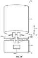
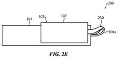
- FIG. 2Eillustrates the view of FIG. 2D after the leads are bent along a second axis, twisting the leads to position the circuit to the side of the battery cell.
- FIG. 3is a schematic, isometric view of a third example of a battery assembly.
- FIG. 4is a schematic, isometric view of a fourth example of a battery assembly.
- FIG. 5is a block diagram illustrating incorporation of a battery assembly including a battery cell and associated circuit into an electronic device.
- FIG. 6is a method diagram illustrating a method for manufacturing a battery assembly. This method may manufacture the battery assembly of FIGS. 2A-2E and/or 3 .
- a battery assemblymay include a battery cell (such as a jellyroll battery cell, a stack-cell battery, and/or any other battery cell structure) or cells with leads extending from the battery and a circuit including a substrate (such as a printed circuit board) and contacts that may or may not extend from the substrate.
- the leadsmay be coupled to the contacts by mechanical or adhesive bonds (which may be electrically conductive), such as welds formed by laser and/or other welding, located on sections of the contacts positioned off of the substrate.
- the contactsmay include a narrow section and a wide section with respect to a width of the contact.
- the terms “narrow” and “wide”are intended to indicate relative dimensions of the sections with respect to one another.
- the respective contactmay be coupled to the substrate at a portion of the narrow section and the respective lead may be coupled to a portion of the wide section and/or the narrow section.
- the contactsmay be L-shaped (or other shapes that may or may not include curvature such as a “T” shape, a “U” shape, a “C” shape, a “Y” shape, and/or other shapes) with one portion of the “L” being the narrow section and the other the wide section.
- the contactsmay each extend from the substrate at a non-right angle with respect to an edge of the substrate. Angling the contacts may enable the sections positioned on the substrate to be smaller while the leads may be coupled to the contacts anywhere along the angled region, thus allowing increasing tolerance for alignment of the leads with the contacts.
- one or more of the leadsmay be formed of a first material while the contacts are formed from a second material.
- the melting point of the first materialmay be lower than the melting point of the second material.
- the leadmay be formed from aluminum and the contact from nickel, as one example. If the mechanical or adhesive bond is a laser weld located on sections of the contacts positioned on the substrate, the laser welds may be formed through the leads placed on the contacts. Coating or cladding the nickel contact in aluminum may facilitate binding of the contacts and leads. The weld may be located on a section of the contact positioned off of the substrate; and sections of the contacts may be folded or placed over the leads such that the laser weld may be formed through the contacts and modification of the material of the leads may not be performed.
- laser weldingis discussed, it is understood that this is not intended to be limiting and other coupling techniques may be used such as ultrasonic welding, conventional welding, soldering, and so on.
- the leadsmay define a narrow section and a wide section with respect to a width of the respective lead. A portion of the narrow section may be coupled to the battery cell and a portion of the wide section and/or the narrow section may be coupled to the respective contact. Such leads may be used in other battery assemblies including conventional battery assemblies.
- the circuitmay include a variety of different components coupled to the substrate. Such components may be operable to perform a variety of functions such as regulating, monitoring, controlling, and/or otherwise managing the battery cell. Such components may include one or more battery management units (BMUs), safety circuits, capacity gauges, and/or other components.
- BMUsbattery management units
- safety circuitssafety circuits
- capacity gaugescapacity gauges
- the leads and/or contactsmay be otherwise configured to further accommodate tolerances and/or alternative designs.
- the leadsmay extend from various surfaces of the battery.
- the leadsmay be bent after coupling which may bring the battery cell and circuit into closer proximity and/or position the circuit with respect to the battery cell in such a manner to as to reduce the overall area and/or volume occupied by the battery and circuit, protect the battery cell and/or the circuit, and so on.
- the leads and/or bonds where leads and contacts are coupledmay also bend along multiple axes.
- the leads and/or contactsmay intersect and/or cross when coupled. In such cases the leads and/or contacts may be insulated from each other prior to coupling, during coupling, and/or after coupling. In various cases, excess portions of the leads and/or contacts that are not part of the coupling may be cut, trimmed, folded, and/or otherwise repositioned prior to coupling, during coupling, and/or after coupling in order to reduce occupied space and/or for other purposes.
- FIG. 1is a schematic, isometric view of a first example of battery assembly 100 .
- a battery cell 101may include leads 104 a and 104 b extending from a front surface 103 .
- a circuit 102may include a substrate 107 (such as a printed circuit board) with one or more components 106 and contacts 105 a and 105 b coupled thereto.
- contacts 105 a and 105 bare positioned entirely on the substrate 107 and have dimensions larger than those of the leads 104 a and 104 b .
- This dimensional differencemay enable the leads to be positioned in larger number of different locations on the contacts for coupling than if the contacts had the same dimensions as the leads, thus accommodating a greater alignment tolerance for coupling the leads and the contacts.
- thismay result in the contacts occupying a larger percentage of the surface area of the substrate, leaving less surface area for component(s) 106 and/or requiring a larger substrate than might otherwise be utilized.
- FIG. 2Ais a schematic, isometric view of a second example of a battery assembly 200 .
- the contacts 205 a and 205 bextend from the substrate 107 .
- the portions of the sections 210 a of the contacts 205 a and 205 b that extend from the substrateare narrower than those of the contacts 105 a and 105 b of FIG. 1 .
- the portions of the sections 210 aare narrower than the portions of the sections 210 b that extend from the substrate, though this may not be the case in various embodiments.
- the contacts 205 a and 205 bare L-shaped with one portion of the “L” being the narrower section and the other the wide section with respect to the width of the contacts 205 a and 205 b .
- the alignment toleranceis substantially increased over the first example battery assembly 100 of FIG. 1 while the sections 210 a positioned on the substrate occupy substantially less surface area of the substrate. This may enable use of a smaller substrate and/or allow more of the surface area of the substrate to be used for the component(s) 106 .
- FIG. 2Billustrates coupling of the leads 104 a and 104 b to the contacts 205 a and 205 b by mechanical or adhesive bonds 211 a and 211 b , respectively, at selected locations on the sections 210 b of the contacts 205 a and 205 b .
- the mechanical or adhesive bondsmay be welds, such as laser welds.
- one or more of the leads 104 a and 104 bmay be formed of a first material with a lower melting point than a second material from which one or more of the contacts 205 a and 205 b are formed (such as aluminum and nickel, respectively). If a laser weld is formed on one or more of leads placed over one or both of the sections 210 a of the welding leads 205 a and/or 205 b positioned on the substrate 107 , due to the differences in the relative melting points of the materials, the first material may be modified, such as by cladding the first material in the second material.
- the leadsmay be folded over or placed under one or both of the welding leads 205 a and/or 205 b and the laser weld may be formed thereupon. As such, modification of the material of the leads may not be performed.
- the sections 210 b of the contacts 205 a and 205 bextend as far as the outside edges of the substrate 107 . However, it is understood that this is an example and that in various implementations the sections 210 b may extend further than the outside edges of the substrate or may not extend to the outside edge of the substrate without departing from the scope of the present disclosure.
- the circuitmay include one or more components 106 that may be operable to perform a variety of functions such as regulating, monitoring, controlling, and/or otherwise managing the battery cell 101 .
- Such componentsmay include one or more battery management units (BMUs), safety circuits, capacity gauges, and/or other components.
- BMUsbattery management units
- safety circuitssafety circuits
- capacity gaugescapacity gauges
- FIG. 2Cillustrates a side plan view of the coupled components of the second example battery assembly 200 of FIG. 2B .
- the leads 104 a and/or 104 bmay be bent after (and/or before) coupling. This bending may bring the battery cell 101 and circuit 102 into closer proximity and/or variously position the circuit with respect to the battery cell to reduce space occupied, protect the battery cell and/or the circuit, and so on.
- FIG. 2Dillustrates the coupled second battery assembly 200 of FIG. 2C after the leads are bent along a first axis 220 (see FIG. 2B ), positioning the circuit above the battery cell.
- bending of the leadsis illustrated and described, in some implementations the contacts 205 a and 205 b and/or the mechanical or adhesive bonds 211 a and 211 b may be bent.
- the leads 104 a and/or 104 bmay be configured to bend along multiple axes that extend in different directions.
- FIG. 2Eillustrates the view of FIG. 2D after the leads are bent along a second axis 221 (see FIG. 2B ), twisting the leads at a twist 230 to position the circuit 102 to the side of the battery cell 101 .
- portions of the leadsmay be bent to fold over the contacts 205 a and 205 b and/or portions of the contacts may be bent to fold over the leads.
- Such foldingmay reduce the volume and/or space occupied by the leads or contacts and/or increase the strength or durability of the coupling. Such folding may be performed before, during, or after coupling.
- the second example battery assembly 200is illustrated and described with particular components configured in a particular arrangement (such as leads formed as leads 104 a and 104 b , contacts formed as contacts 205 a and 205 b ), it is understood that this is an example. In various implementations other numbers of components configured in other arrangements may be utilized without departing from the scope of the present disclosure.
- the leads 104 a and 104 b and the contacts 205 a and 205 bare shown as not intersecting and/or crossing at any point between the battery cell 101 and the circuit 102 .
- the leads of a battery cell and/or contacts of a circuitmay intersect and/or cross at one or more points before, during, or after coupling.
- the leads and/or contacts at such points and/or other pointsmay be insulated from each other. Such insulation may be applied and/or configured prior to coupling, during coupling, and/or after coupling.
- FIG. 2Billustrates the mechanical or adhesive bonds 211 a and 211 b as only occupying a small portion of the sections 210 b of the contacts 205 a and 205 b .
- the remaining portions of the sections 210 b after couplingmay be cut away and/or folded over the mechanical or adhesive bonds in order to occupy less space and/or make room for other components.
- FIG. 3is a schematic, isometric view of a third example of a battery assembly 300 .
- the contacts 305 a and 305 bextend from the substrate 107 at a non-right angle 340 with respect to the edge of the substrate.
- the sections of the contacts 305 a and 305 b that are positioned on the substrateare narrower than those of the contacts 105 a and 105 b of FIG. 1 .
- the contacts 305 a and 305 bare illustrated and described as extending from the substrate 107 at a non-right angle, it is understood that this is an example.
- the contactsmay be curved, the contacts may extend at different non-right angles than each other, and so on without departing from the scope of the present disclosure.
- the leads 304 a and 304 bmay extend from the battery cell 301 at a non-right angle, the leads be curved, the leads may extend at different non-right angles than each other, and so on without departing from the scope of the present disclosure.
- the number of locations where the leads 304 a and 304 b may be positioned on the sections of the contacts 305 a and 305 b positioned off the substrate for couplingmay be increased as compared with a perpendicular arrangement regarding to the substrate outside edge. This may substantially increase the alignment tolerance over the first example battery assembly 100 of FIG. 1 while the sections positioned on the substrate occupy substantially less surface area of the substrate. This may enable use of a smaller substrate and/or allow more of the surface area of the substrate to be used for the component(s) 106 .
- the lead 304 bis shown as extending from a back surface 301 of the battery cell 101 and is configured to project in the same orientation as the lead 304 a by being bent and run across the top of the battery down past the front surface 103 .
- this configuration of the leads 304 a and 304 bis optional and any battery cell described herein may be utilized with the contacts 305 a and 305 b .
- the portion of the lead 304 b running across the battery cellmay be insulated.
- FIG. 4is a schematic, isometric view of components of a fourth example of a battery assembly 400 .
- the sections 410 a of the leads 404 a and 404 bextend from the front surface 103 of the battery cell 101 are narrower than the sections 410 b .
- the leads 404 a and 404 bare L-shaped.
- the contacts 405 a and 405 b positioned on the substrate 107are narrower than those of the contacts 105 a and 105 b of FIG. 1 .
- the alignment toleranceis substantially increased over the first example battery assembly 100 of FIG. 1 while the contacts 405 a and 405 b occupy substantially less surface area of the substrate. This may enable use of a smaller substrate and/or allow more of the surface area of the substrate to be used for the component(s) 106 . Additionally, in some implementations the substrate 107 may include circuit traces and/or other components positioned under portions of the leads 404 a and 404 b that are not coupled to the contacts 405 a and 405 b .
- insulative materialmay be positioned under such portions of the leads 404 a and 404 b and/or over the circuit traces and/or other components to prevent interference between the portions of the leads 404 a and 404 b and the circuit traces and/or other components.
- L-shaped leads 404 a and 404 bare illustrated and described as being used in an embodiment where the contacts 405 a and 405 b do not extend from the substrate 107 , it is understood that this is an example. In various implementations, such leads may be used in battery assemblies including circuits where the contacts extend from the substrate (such as the example battery assemblies 200 and 300 of FIGS. 2A-2E and 3 .
- FIG. 5is a block diagram illustrating incorporation of a battery assembly (Such as the battery assemblies 200 , 300 , and/or 400 of FIGS. 2A-2E, 3 , and/or 4 ) including a battery cell 101 and associated circuit 102 into an electronic device 501 .
- the electronic devicemay be a laptop computer, a mobile computer, a smart phone, a cellular telephone, a tablet computer, a digital media player, a wearable device, an electronic kitchen appliance, a display, an accessory, and/or any other electronic device.
- the battery cell 101 and/or the circuit 102may be connected to one or more electronic components 502 of the electronic device 501 .
- Such electronic componentsmay include one or more processing units, one or more communication components, one or more input/output components, one or more non-transitory storage media (which may take the form of, but is not limited to, a magnetic storage medium; optical storage medium; magneto-optical storage medium; read only memory; random access memory; erasable programmable memory; flash memory; and so on), and/or any other such components.
- the componentmay utilize power provided by the battery cell.
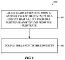
- FIG. 6is a method diagram illustrating a method 600 for manufacturing a battery assembly. This method may manufacture the battery assembly of FIGS. 2A-2E and/or 3 .
- the flowmay begin at block 601 where leads extending from a battery cell are aligned with contacts of a circuit that are coupled to a substrate and extend from the substrate.
- the flowmay then proceed to block 602 where the leads may be coupled to the contacts.
- the couplingmay include forming mechanical or adhesive bonds that may be located on sections of the contacts positioned off of the substrate.
- such a coupling operationmay include laser welding the contacts to the leads (and/or the leads to the contacts).
- laser welding the contacts to the leadsmay include laser welding a nickel contact to an aluminum lead (and/or other combinations of materials where the material forming the contact melts at a higher temperature than the material forming the lead) through a surface of the nickel contact.
- the coupling operationmay include selecting coupling locations on the contacts out of a number of different possible coupling locations.
- the method 600may include the additional operation of bending the leads. Such bending may alter the position of the circuit with respect to the battery cell. Further, such bending may bend the leads along multiple axes. In various cases, the contacts may be bent in addition to and/or instead of bending the leads.
- the method 600is illustrated and described at block 602 as forming the circuit by coupling contacts to a substrate such that the contacts extend from the substrate.
- the contacts coupled to the substratemay not extend from the substrate.
- the leads extending from the battery cellmay be shaped such that sections of the leads are wider than sections coupled to a surface of the battery cell and/or may extend from the surface of the battery at an acute angle with respect to the surface of the battery.
- the leadsmay be L-shaped.
- a battery assemblymay include a battery cell (such as a jellyroll battery cell) with leads extending from the battery and a circuit including a substrate (such as a printed circuit board) and contacts that extend from the substrate.
- the leadsmay be coupled to the contacts by mechanical or adhesive bonds, such as welds formed by laser and/or other welding, located on sections of the contacts positioned off of the substrate.
- the methods disclosedmay be implemented as sets of instructions or software readable by a device. Further, it is understood that the specific order or hierarchy of steps in the methods disclosed are examples of sample approaches. In other embodiments, the specific order or hierarchy of steps in the method can be rearranged while remaining within the disclosed subject matter.
- the accompanying method claimspresent elements of the various steps in a sample order, and are not necessarily meant to be limited to the specific order or hierarchy presented.
- a computer program product, or softwarethat may include a non-transitory machine-readable medium having stored thereon instructions, may be used to program a computer manufacturing system (or other electronic devices) to construct battery assemblies and/or electronic devices including such battery assemblies according to the present disclosure.
- a non-transitory machine-readable mediumincludes any mechanism for storing information in a form (e.g., software, processing application) readable by a machine (e.g., a computer).
- the non-transitory machine-readable mediummay take the form of, but is not limited to, a magnetic storage medium (e.g., floppy diskette, video cassette, and so on); optical storage medium (e.g., CD-ROM); magneto-optical storage medium; read only memory (ROM); random access memory (RAM); erasable programmable memory (e.g., EPROM and EEPROM); flash memory; and so on.
- a magnetic storage mediume.g., floppy diskette, video cassette, and so on
- optical storage mediume.g., CD-ROM
- magneto-optical storage mediume.g., magneto-optical storage medium
- ROMread only memory
- RAMrandom access memory
- EPROM and EEPROMerasable programmable memory
- flash memoryand so on.
Landscapes
- Engineering & Computer Science (AREA)
- Physics & Mathematics (AREA)
- Optics & Photonics (AREA)
- Plasma & Fusion (AREA)
- Mechanical Engineering (AREA)
- Chemical & Material Sciences (AREA)
- Chemical Kinetics & Catalysis (AREA)
- Electrochemistry (AREA)
- General Chemical & Material Sciences (AREA)
- Microelectronics & Electronic Packaging (AREA)
- Manufacturing & Machinery (AREA)
- Battery Mounting, Suspending (AREA)
Abstract
Description
Claims (13)
Priority Applications (1)
| Application Number | Priority Date | Filing Date | Title |
|---|---|---|---|
| US14/832,683US10930915B2 (en) | 2014-09-02 | 2015-08-21 | Coupling tolerance accommodating contacts or leads for batteries |
Applications Claiming Priority (2)
| Application Number | Priority Date | Filing Date | Title |
|---|---|---|---|
| US201462044570P | 2014-09-02 | 2014-09-02 | |
| US14/832,683US10930915B2 (en) | 2014-09-02 | 2015-08-21 | Coupling tolerance accommodating contacts or leads for batteries |
Publications (2)
| Publication Number | Publication Date |
|---|---|
| US20160064719A1 US20160064719A1 (en) | 2016-03-03 |
| US10930915B2true US10930915B2 (en) | 2021-02-23 |
Family
ID=55403554
Family Applications (1)
| Application Number | Title | Priority Date | Filing Date |
|---|---|---|---|
| US14/832,683Expired - Fee RelatedUS10930915B2 (en) | 2014-09-02 | 2015-08-21 | Coupling tolerance accommodating contacts or leads for batteries |
Country Status (1)
| Country | Link |
|---|---|
| US (1) | US10930915B2 (en) |
Families Citing this family (12)
| Publication number | Priority date | Publication date | Assignee | Title |
|---|---|---|---|---|
| US9711770B2 (en) | 2012-11-27 | 2017-07-18 | Apple Inc. | Laminar battery system |
| US10033029B2 (en) | 2012-11-27 | 2018-07-24 | Apple Inc. | Battery with increased energy density and method of manufacturing the same |
| US10211433B2 (en) | 2012-11-27 | 2019-02-19 | Apple Inc. | Battery packaging |
| US9899661B2 (en) | 2013-03-13 | 2018-02-20 | Apple Inc. | Method to improve LiCoO2 morphology in thin film batteries |
| US9887403B2 (en) | 2013-03-15 | 2018-02-06 | Apple Inc. | Thin film encapsulation battery systems |
| US9601751B2 (en) | 2013-03-15 | 2017-03-21 | Apple Inc. | Annealing method for thin film electrodes |
| US10141600B2 (en) | 2013-03-15 | 2018-11-27 | Apple Inc. | Thin film pattern layer battery systems |
| US9570775B2 (en) | 2013-03-15 | 2017-02-14 | Apple Inc. | Thin film transfer battery systems |
| GB2541917A (en)* | 2015-09-04 | 2017-03-08 | Tirius Ltd | A method for welding wires comprising aluminium |
| EP3480868B1 (en) | 2017-11-03 | 2025-06-25 | Greatbatch Ltd. | Laser brazed component and method therefor |
| CN109719434B (en)* | 2019-02-19 | 2024-07-23 | 富基电子(深圳)有限公司 | Spot welding equipment for battery production |
| US11824220B2 (en) | 2020-09-03 | 2023-11-21 | Apple Inc. | Electronic device having a vented battery barrier |
Citations (108)
| Publication number | Priority date | Publication date | Assignee | Title |
|---|---|---|---|---|
| US3655455A (en) | 1964-07-16 | 1972-04-11 | Globe Union Inc | Method for the manufacture of batteries |
| US4369225A (en) | 1979-12-27 | 1983-01-18 | Toyoda Gosei Kabushiki Kaisha | Flexible lustrously metallized resinous articles and a process for manufacturing same |
| JPS6132951A (en) | 1984-07-25 | 1986-02-15 | Shin Kobe Electric Mach Co Ltd | sealed lead acid battery |
| JPS63314770A (en) | 1987-06-17 | 1988-12-22 | Matsushita Electric Ind Co Ltd | Manufacturing method of sealed lead-acid battery |
| US5134046A (en) | 1990-04-04 | 1992-07-28 | Ultralife Batteries, Inc. | Battery with metal foil coated plastic housing |
| US5523179A (en) | 1994-11-23 | 1996-06-04 | Polyplus Battery Company | Rechargeable positive electrode |
| US5554459A (en) | 1996-01-23 | 1996-09-10 | Bell Communications Research, Inc. | Material and method for low internal resistance LI-ion battery |
| US5561004A (en) | 1994-02-25 | 1996-10-01 | Bates; John B. | Packaging material for thin film lithium batteries |
| CN1153311A (en) | 1995-04-21 | 1997-07-02 | 大宇电子株式会社 | Method for forming array of thin film actuated mirrors |
| EP0792741A1 (en) | 1996-02-27 | 1997-09-03 | Nihon Matai Company Limited | Inflatable bag body and method for producing same |
| US6001138A (en) | 1997-08-22 | 1999-12-14 | Micron Communications, Inc. | Methods of forming battery electrodes |
| EP0975031A1 (en) | 1998-02-05 | 2000-01-26 | Dai Nippon Printing Co., Ltd. | Sheet for cell case and cell device |
| US6180278B1 (en) | 1998-07-21 | 2001-01-30 | Eveready Battery Company, Inc. | Reclamation of active material from metal hydride electrochemical cells |
| US6200634B1 (en) | 1995-05-26 | 2001-03-13 | Mattson Technology, Inc. | Thermal processing system with supplemental resistive heater and shielded optical pyrometry |
| US20010032666A1 (en) | 2000-03-24 | 2001-10-25 | Inegrated Power Solutions Inc. | Integrated capacitor-like battery and associated method |
| US6319631B1 (en) | 1999-09-08 | 2001-11-20 | Motorola, Inc. | Contact system for interconnection of substrate and battery cell |
| US6410189B1 (en) | 1998-12-25 | 2002-06-25 | Tokai Aluminum Fiol Co., Ltd. | Current collectors for battery |
| US20020127362A1 (en) | 2001-03-01 | 2002-09-12 | The University Of Chicago | Flexible laminates and housings for batteries |
| US6610572B1 (en) | 1999-11-26 | 2003-08-26 | Fuji Electric Co., Ltd. | Semiconductor device and method for manufacturing the same |
| US20030160589A1 (en) | 2002-02-28 | 2003-08-28 | Victor Krasnov | Rechargeable battery having permeable anode current collector |
| US20030180621A1 (en) | 2000-08-30 | 2003-09-25 | Isao Matsumoto | Non-sintered type thin electrode for battery, battery using same and process for same |
| US6632563B1 (en) | 2000-09-07 | 2003-10-14 | Front Edge Technology, Inc. | Thin film battery and method of manufacture |
| US20050079418A1 (en) | 2003-10-14 | 2005-04-14 | 3M Innovative Properties Company | In-line deposition processes for thin film battery fabrication |
| US6893772B2 (en) | 1993-11-19 | 2005-05-17 | Medtronic, Inc. | Current collector for lithium electrode |
| US20050153078A1 (en) | 2003-12-05 | 2005-07-14 | Conductive Inkjet Technology Limited | Formation of solid layers on substrates |
| US20050211313A1 (en) | 1999-07-30 | 2005-09-29 | The Procter & Gamble Company | Microvalve for controlling fluid flow |
| US20050250010A1 (en) | 2002-12-05 | 2005-11-10 | Tdk Corporation | Coating liquid for electrode formation, electrode. electrochemical device, and process for producing these |
| US20060068292A1 (en) | 2004-09-30 | 2006-03-30 | Sony Corporation | Anode active material and battery using the same |
| US20070099078A1 (en) | 2002-01-10 | 2007-05-03 | Ji-Guang Zhang | Packaged thin film batteries and methods of packaging thin film batteries |
| EP1804315A2 (en) | 2005-12-29 | 2007-07-04 | Samsung SDI Co., Ltd. | Pouch-type battery case, battery and method of making the same |
| US7285334B1 (en) | 1999-04-08 | 2007-10-23 | Dai Nippon Printing Co., Ltd. | Material for packaging cell, bag for packaging cell, and its production method |
| US7297441B2 (en) | 1998-10-23 | 2007-11-20 | Sony Corporation | Nonaqueous-electrolyte secondary battery |
| WO2008007867A1 (en) | 2006-07-14 | 2008-01-17 | Bps.Co., Ltd. | Method of making battery using as case with aluminium multilayered films |
| US20080032236A1 (en) | 2006-07-18 | 2008-02-07 | Wallace Mark A | Method and apparatus for solid-state microbattery photolithographic manufacture, singulation and passivation |
| US20090181303A1 (en) | 2008-01-11 | 2009-07-16 | Neudecker Bernd J | Thin Film Encapsulation for Thin Film Batteries and Other Devices |
| US20090193649A1 (en) | 2006-07-03 | 2009-08-06 | Koninklijke Philips Electronics N.V. | Method for the manufacture of a thin film electrochemical energy source and device |
| US20090208754A1 (en) | 2001-09-28 | 2009-08-20 | Vitex Systems, Inc. | Method for edge sealing barrier films |
| US20090214899A1 (en) | 2008-02-27 | 2009-08-27 | Cymbet Corporation | Battery layout incorporating full metal edge seal |
| US7585582B2 (en) | 2006-06-28 | 2009-09-08 | Nan Ya Printed Circuit Board Corporation | Fuel cell module utilizing wave-shaped flow board |
| EP2105983A1 (en) | 2008-03-26 | 2009-09-30 | Fuji Jukogyo Kabushiki Kaisha | Manufacturing process of electrode |
| US20090317708A1 (en) | 2006-07-24 | 2009-12-24 | Oliver Brandl | Plastic laminate film |
| US20100015516A1 (en) | 2008-07-21 | 2010-01-21 | Junwei Jiang | Cathode compositions for lithium-ion electrochemical cells |
| CN101640968A (en) | 2008-08-01 | 2010-02-03 | 英业达股份有限公司 | Electrostatic guiding structure using metal oxide generated by anodic treatment |
| US20100035152A1 (en) | 2008-08-05 | 2010-02-11 | Sakti3, Inc. | Electrochemical cell including functionally graded and architectured components and methods |
| TW201010094A (en) | 2008-08-29 | 2010-03-01 | Univ Nat Taiwan | Nano or micro-structured PN junction diode array thin-film solar cell and manufacturing method thereof |
| US20100066683A1 (en) | 2008-09-17 | 2010-03-18 | Shih-Chang Chang | Method for Transferring Thin Film to Substrate |
| US7801613B2 (en) | 2007-04-26 | 2010-09-21 | Medtronic, Inc. | Metal injection molded titanium alloy housing for implantable medical devices |
| US7811702B2 (en) | 2004-08-03 | 2010-10-12 | Commissariat à l'Energie Atomique | Microbattery comprising through-connections and production method thereof |
| TW201108441A (en) | 2009-08-17 | 2011-03-01 | Nat Univ Chung Hsing | Manufacturing method for stacking type solar cells and its product thereof |
| US20110076550A1 (en) | 2005-03-25 | 2011-03-31 | Front Edge Technology, Inc. | Battery with protective packaging |
| US7931989B2 (en) | 2005-07-15 | 2011-04-26 | Cymbet Corporation | Thin-film batteries with soft and hard electrolyte layers and method |
| US7935439B2 (en) | 2005-04-27 | 2011-05-03 | Samsung Sdi Co., Ltd. | Pouch type lithium secondary battery |
| US7939195B2 (en) | 2004-12-23 | 2011-05-10 | Commissariat A L'energie Atomique | Structured electrolyte for micro-battery |
| US20110123844A1 (en) | 2009-11-20 | 2011-05-26 | Apple Inc. | Pressure-relief mechanism to improve safety in lithium-polymer battery cells |
| US20110129594A1 (en) | 2009-09-22 | 2011-06-02 | Byung-Sung Kwak | Thin-film battery methods for complexity reduction |
| US7959769B2 (en) | 2004-12-08 | 2011-06-14 | Infinite Power Solutions, Inc. | Deposition of LiCoO2 |
| US20110177398A1 (en) | 2008-08-05 | 2011-07-21 | Sion Power Corporation | Electrochemical cell |
| US20110183183A1 (en) | 2010-01-26 | 2011-07-28 | Grady Steven C | Battery arrays, constructions and method |
| US20110195271A1 (en) | 2010-02-09 | 2011-08-11 | Apple Inc. | Cast Metal Parts With Cosmetic Surfaces And Methods Of Making Same |
| US20110200868A1 (en)* | 2005-07-15 | 2011-08-18 | Klaassen Jody J | THIN-FILM BATTERIES WITH POLYMER AND LiPON ELECTROLYTE LAYERS AND METHOD |
| US8044813B1 (en) | 2006-11-16 | 2011-10-25 | Semiconductor Energy Laboratory Co., Ltd. | Radio field intensity measurement device, and radio field intensity detector and game console using the same |
| US20110281141A1 (en)* | 2010-05-13 | 2011-11-17 | Samsung Sdi Co., Ltd. | Battery pack |
| US20110294015A1 (en) | 2010-05-25 | 2011-12-01 | Robert Bosch Gmbh | Method and Apparatus for Production of a Thin-Film Battery |
| US20110311876A1 (en) | 2008-11-18 | 2011-12-22 | Johnson Controls Technology Company | Electrical power storage devices |
| US20120028089A1 (en) | 2009-04-30 | 2012-02-02 | Jyrki Mustakallio | Gas release from a battery cell |
| US20120078317A1 (en) | 2010-08-12 | 2012-03-29 | Francis Wang | Carbon monofluoride impregnated current collector including a 3d framework |
| US20120088151A1 (en) | 2010-10-08 | 2012-04-12 | Semiconductor Energy Laboratory Co., Ltd. | Positive-electrode active material and power storage device |
| US20120100460A1 (en) | 2010-10-20 | 2012-04-26 | Empire Technology Development Llc | Calcium hexaboride anodes for electrochemical cells |
| US8168322B2 (en) | 2005-03-25 | 2012-05-01 | Front Edge Technology, Inc. | Thin film battery with protective packaging |
| US20120135288A1 (en) | 2009-02-27 | 2012-05-31 | Li-Tec Battery Gmbh | Galvanic cell having a frame and method for the production of said galvanic cell |
| WO2012086557A1 (en) | 2010-12-24 | 2012-06-28 | 京セラ株式会社 | Lithium rechargeable battery |
| WO2012090929A1 (en) | 2010-12-27 | 2012-07-05 | Baba Mamoru | Manufacturing method for thin film lithium secondary battery, and thin film lithium secondary battery |
| EP2481499A2 (en) | 2011-02-01 | 2012-08-01 | Zoltrix Material (Guangzhou) Limited | Method and device for manufacturing cover including multiple metal layers |
| WO2012114162A1 (en) | 2011-02-26 | 2012-08-30 | Etv Energy Ltd. | Pouch cell comprising an empty -volume defining component |
| US8263256B2 (en) | 2004-12-10 | 2012-09-11 | Sony Corporation | Cell |
| US8293402B2 (en)* | 2008-01-04 | 2012-10-23 | Samsung Sdi Co., Ltd. | Battery with circuit board and lead terminals |
| JP2013004173A (en) | 2011-06-10 | 2013-01-07 | Ulvac Japan Ltd | Method for manufacturing thin-film lithium secondary battery, substrate processing apparatus, and thin-film lithium secondary battery |
| JP2013021347A (en) | 2012-09-06 | 2013-01-31 | Taiyo Yuden Co Ltd | Electrochemical device |
| US20130029205A1 (en) | 2010-02-08 | 2013-01-31 | Qinetiq Limited | Thin Electrochemical Cell |
| WO2013031195A1 (en) | 2011-08-29 | 2013-03-07 | パナソニック株式会社 | Thin battery electrode group, thin battery, and electronic device |
| US8431264B2 (en) | 2002-08-09 | 2013-04-30 | Infinite Power Solutions, Inc. | Hybrid thin-film battery |
| CN103094512A (en) | 2013-01-17 | 2013-05-08 | 苏州凯虹高分子科技有限公司 | Safety valve of lithium battery |
| US8445130B2 (en) | 2002-08-09 | 2013-05-21 | Infinite Power Solutions, Inc. | Hybrid thin-film battery |
| US20130176654A1 (en) | 2012-01-06 | 2013-07-11 | Polytronics Technology Corp. | Over-current protection device and battery protection circuit assembly containing the same |
| US8518583B2 (en) | 2009-09-18 | 2013-08-27 | Toyota Jidosha Kabushiki Kaisha | Air cathode and metal-air battery |
| US20130344363A1 (en) | 2011-12-10 | 2013-12-26 | Deepak Upadhyaya | Li-ion battery and battery active components on metal wire |
| US20140007418A1 (en) | 2011-06-17 | 2014-01-09 | Applied Materials, Inc. | Mask-Less Fabrication of Thin Film Batteries |
| US8669345B2 (en) | 2006-01-27 | 2014-03-11 | Biogen Idec Ma Inc. | Nogo receptor antagonists |
| US8691447B2 (en) | 2008-02-25 | 2014-04-08 | Alliance For Sustainable Energy, Llc | Homogeneous, dual layer, solid state, thin film deposition for structural and/or electrochemical characteristics |
| US20140147742A1 (en) | 2012-11-27 | 2014-05-29 | Apple Inc. | Battery with Increased Energy Density and Method of Manufacturing the Same |
| US20140147737A1 (en) | 2012-11-27 | 2014-05-29 | Apple Inc. | Battery Packaging |
| US20140147731A1 (en) | 2012-11-27 | 2014-05-29 | Apple Inc. | Laminar Battery System |
| US8822059B2 (en) | 2011-12-28 | 2014-09-02 | Tsinghua University | Lithium ion battery |
| US20140264915A1 (en) | 2013-03-15 | 2014-09-18 | Chao-Yuan Huang | Stacked Integrated Circuit System |
| US20140273890A1 (en) | 2013-03-15 | 2014-09-18 | Apple Inc. | Thin Film Transfer Battery Systems |
| US20140272190A1 (en) | 2013-03-15 | 2014-09-18 | Apple Inc. | Annealing Method for Thin Film Electrodes |
| US20140272560A1 (en) | 2013-03-13 | 2014-09-18 | Apple Inc. | Method to Improve LiCoO2 Morphology in Thin Film Batteries |
| US20140265915A1 (en) | 2013-03-15 | 2014-09-18 | Apple Inc. | Thin Film Encapsulation Battery Systems |
| US20140272541A1 (en) | 2013-03-15 | 2014-09-18 | Apple Inc. | Thin Film Pattern Layer Battery Systems |
| US20140272561A1 (en) | 2013-03-14 | 2014-09-18 | Apple Inc. | Alternative Current Collectors for Thin Film Batteries and Method for Making the Same |
| US8956761B2 (en) | 2009-11-30 | 2015-02-17 | Oerlikon Advanced Technologies Ag | Lithium ion battery and method for manufacturing of such battery |
| US20150325862A1 (en) | 2012-12-19 | 2015-11-12 | Applied Materials, Inc. | Mask-less fabrication of vertical thin film batteries |
| US9209497B2 (en) | 2012-12-17 | 2015-12-08 | Infineon Technologies Ag | Sensor module and battery elements |
| US20160093837A1 (en) | 2014-09-30 | 2016-03-31 | Apple Inc. | Efficient Battery Pouch |
| US9673481B2 (en) | 2009-02-03 | 2017-06-06 | Sony Corporation | Thin film solid state lithium ion secondary battery and method of manufacturing the same |
| US9911947B2 (en) | 2013-09-11 | 2018-03-06 | Samsung Sdi Co., Ltd. | Battery cell for electronic device |
| WO2018108713A1 (en) | 2016-12-13 | 2018-06-21 | Lithium Energy and Power GmbH & Co. KG | Battery cell comprising a safety valve |
| WO2019163550A1 (en) | 2018-02-26 | 2019-08-29 | 三洋電機株式会社 | Battery pack |
- 2015
- 2015-08-21USUS14/832,683patent/US10930915B2/ennot_activeExpired - Fee Related
Patent Citations (130)
| Publication number | Priority date | Publication date | Assignee | Title |
|---|---|---|---|---|
| US3655455A (en) | 1964-07-16 | 1972-04-11 | Globe Union Inc | Method for the manufacture of batteries |
| US4369225A (en) | 1979-12-27 | 1983-01-18 | Toyoda Gosei Kabushiki Kaisha | Flexible lustrously metallized resinous articles and a process for manufacturing same |
| JPS6132951A (en) | 1984-07-25 | 1986-02-15 | Shin Kobe Electric Mach Co Ltd | sealed lead acid battery |
| JPS63314770A (en) | 1987-06-17 | 1988-12-22 | Matsushita Electric Ind Co Ltd | Manufacturing method of sealed lead-acid battery |
| US5134046A (en) | 1990-04-04 | 1992-07-28 | Ultralife Batteries, Inc. | Battery with metal foil coated plastic housing |
| US6893772B2 (en) | 1993-11-19 | 2005-05-17 | Medtronic, Inc. | Current collector for lithium electrode |
| US20060210880A1 (en) | 1993-11-19 | 2006-09-21 | Medtronic, Inc. | Current collector |
| US5561004A (en) | 1994-02-25 | 1996-10-01 | Bates; John B. | Packaging material for thin film lithium batteries |
| US5523179A (en) | 1994-11-23 | 1996-06-04 | Polyplus Battery Company | Rechargeable positive electrode |
| CN1144017A (en) | 1994-11-23 | 1997-02-26 | 波利普拉斯电池有限公司 | Rechargeable positive electrode |
| CN1153311A (en) | 1995-04-21 | 1997-07-02 | 大宇电子株式会社 | Method for forming array of thin film actuated mirrors |
| US6200634B1 (en) | 1995-05-26 | 2001-03-13 | Mattson Technology, Inc. | Thermal processing system with supplemental resistive heater and shielded optical pyrometry |
| US5554459A (en) | 1996-01-23 | 1996-09-10 | Bell Communications Research, Inc. | Material and method for low internal resistance LI-ion battery |
| EP0792741A1 (en) | 1996-02-27 | 1997-09-03 | Nihon Matai Company Limited | Inflatable bag body and method for producing same |
| US6001138A (en) | 1997-08-22 | 1999-12-14 | Micron Communications, Inc. | Methods of forming battery electrodes |
| US20040029001A1 (en)* | 1997-10-14 | 2004-02-12 | Dai Nippon Printing Co., Ltd. | Battery case forming sheet and battery packet |
| EP0975031A1 (en) | 1998-02-05 | 2000-01-26 | Dai Nippon Printing Co., Ltd. | Sheet for cell case and cell device |
| CN1262790A (en) | 1998-02-05 | 2000-08-09 | 大日本印刷株式会社 | Battery case forming sheets and battery assemblies |
| US6180278B1 (en) | 1998-07-21 | 2001-01-30 | Eveready Battery Company, Inc. | Reclamation of active material from metal hydride electrochemical cells |
| US7297441B2 (en) | 1998-10-23 | 2007-11-20 | Sony Corporation | Nonaqueous-electrolyte secondary battery |
| US6410189B1 (en) | 1998-12-25 | 2002-06-25 | Tokai Aluminum Fiol Co., Ltd. | Current collectors for battery |
| US7285334B1 (en) | 1999-04-08 | 2007-10-23 | Dai Nippon Printing Co., Ltd. | Material for packaging cell, bag for packaging cell, and its production method |
| US20050211313A1 (en) | 1999-07-30 | 2005-09-29 | The Procter & Gamble Company | Microvalve for controlling fluid flow |
| US6319631B1 (en) | 1999-09-08 | 2001-11-20 | Motorola, Inc. | Contact system for interconnection of substrate and battery cell |
| US6610572B1 (en) | 1999-11-26 | 2003-08-26 | Fuji Electric Co., Ltd. | Semiconductor device and method for manufacturing the same |
| US20010032666A1 (en) | 2000-03-24 | 2001-10-25 | Inegrated Power Solutions Inc. | Integrated capacitor-like battery and associated method |
| US20030180621A1 (en) | 2000-08-30 | 2003-09-25 | Isao Matsumoto | Non-sintered type thin electrode for battery, battery using same and process for same |
| US6632563B1 (en) | 2000-09-07 | 2003-10-14 | Front Edge Technology, Inc. | Thin film battery and method of manufacture |
| US20020127362A1 (en) | 2001-03-01 | 2002-09-12 | The University Of Chicago | Flexible laminates and housings for batteries |
| US20090208754A1 (en) | 2001-09-28 | 2009-08-20 | Vitex Systems, Inc. | Method for edge sealing barrier films |
| US7960054B2 (en) | 2002-01-10 | 2011-06-14 | Excellatron Solid State Llc | Packaged thin film batteries |
| US20070099078A1 (en) | 2002-01-10 | 2007-05-03 | Ji-Guang Zhang | Packaged thin film batteries and methods of packaging thin film batteries |
| US6713987B2 (en) | 2002-02-28 | 2004-03-30 | Front Edge Technology, Inc. | Rechargeable battery having permeable anode current collector |
| US20030160589A1 (en) | 2002-02-28 | 2003-08-28 | Victor Krasnov | Rechargeable battery having permeable anode current collector |
| US8431264B2 (en) | 2002-08-09 | 2013-04-30 | Infinite Power Solutions, Inc. | Hybrid thin-film battery |
| US8445130B2 (en) | 2002-08-09 | 2013-05-21 | Infinite Power Solutions, Inc. | Hybrid thin-film battery |
| US20050250010A1 (en) | 2002-12-05 | 2005-11-10 | Tdk Corporation | Coating liquid for electrode formation, electrode. electrochemical device, and process for producing these |
| US20050079418A1 (en) | 2003-10-14 | 2005-04-14 | 3M Innovative Properties Company | In-line deposition processes for thin film battery fabrication |
| US20050153078A1 (en) | 2003-12-05 | 2005-07-14 | Conductive Inkjet Technology Limited | Formation of solid layers on substrates |
| US7811702B2 (en) | 2004-08-03 | 2010-10-12 | Commissariat à l'Energie Atomique | Microbattery comprising through-connections and production method thereof |
| TWI306319B (en) | 2004-09-30 | 2009-02-11 | Sony Corp | Anode active material and battery using the same |
| US7927744B2 (en) | 2004-09-30 | 2011-04-19 | Sony Corporation | Anode active material and battery using the same |
| US20060068292A1 (en) | 2004-09-30 | 2006-03-30 | Sony Corporation | Anode active material and battery using the same |
| US7959769B2 (en) | 2004-12-08 | 2011-06-14 | Infinite Power Solutions, Inc. | Deposition of LiCoO2 |
| US8263256B2 (en) | 2004-12-10 | 2012-09-11 | Sony Corporation | Cell |
| US7939195B2 (en) | 2004-12-23 | 2011-05-10 | Commissariat A L'energie Atomique | Structured electrolyte for micro-battery |
| US20120251867A1 (en) | 2005-03-25 | 2012-10-04 | Victor Krasnov | Thin film battery with electrical connector connecting battery cells |
| US8679674B2 (en) | 2005-03-25 | 2014-03-25 | Front Edge Technology, Inc. | Battery with protective packaging |
| US8168322B2 (en) | 2005-03-25 | 2012-05-01 | Front Edge Technology, Inc. | Thin film battery with protective packaging |
| US20110076550A1 (en) | 2005-03-25 | 2011-03-31 | Front Edge Technology, Inc. | Battery with protective packaging |
| US7935439B2 (en) | 2005-04-27 | 2011-05-03 | Samsung Sdi Co., Ltd. | Pouch type lithium secondary battery |
| US7931989B2 (en) | 2005-07-15 | 2011-04-26 | Cymbet Corporation | Thin-film batteries with soft and hard electrolyte layers and method |
| US20110200868A1 (en)* | 2005-07-15 | 2011-08-18 | Klaassen Jody J | THIN-FILM BATTERIES WITH POLYMER AND LiPON ELECTROLYTE LAYERS AND METHOD |
| EP1804315A2 (en) | 2005-12-29 | 2007-07-04 | Samsung SDI Co., Ltd. | Pouch-type battery case, battery and method of making the same |
| US8669345B2 (en) | 2006-01-27 | 2014-03-11 | Biogen Idec Ma Inc. | Nogo receptor antagonists |
| US7585582B2 (en) | 2006-06-28 | 2009-09-08 | Nan Ya Printed Circuit Board Corporation | Fuel cell module utilizing wave-shaped flow board |
| US20090193649A1 (en) | 2006-07-03 | 2009-08-06 | Koninklijke Philips Electronics N.V. | Method for the manufacture of a thin film electrochemical energy source and device |
| WO2008007867A1 (en) | 2006-07-14 | 2008-01-17 | Bps.Co., Ltd. | Method of making battery using as case with aluminium multilayered films |
| US20080032236A1 (en) | 2006-07-18 | 2008-02-07 | Wallace Mark A | Method and apparatus for solid-state microbattery photolithographic manufacture, singulation and passivation |
| US20090317708A1 (en) | 2006-07-24 | 2009-12-24 | Oliver Brandl | Plastic laminate film |
| US8044813B1 (en) | 2006-11-16 | 2011-10-25 | Semiconductor Energy Laboratory Co., Ltd. | Radio field intensity measurement device, and radio field intensity detector and game console using the same |
| US7801613B2 (en) | 2007-04-26 | 2010-09-21 | Medtronic, Inc. | Metal injection molded titanium alloy housing for implantable medical devices |
| US8293402B2 (en)* | 2008-01-04 | 2012-10-23 | Samsung Sdi Co., Ltd. | Battery with circuit board and lead terminals |
| US20090181303A1 (en) | 2008-01-11 | 2009-07-16 | Neudecker Bernd J | Thin Film Encapsulation for Thin Film Batteries and Other Devices |
| US8691447B2 (en) | 2008-02-25 | 2014-04-08 | Alliance For Sustainable Energy, Llc | Homogeneous, dual layer, solid state, thin film deposition for structural and/or electrochemical characteristics |
| US20090214899A1 (en) | 2008-02-27 | 2009-08-27 | Cymbet Corporation | Battery layout incorporating full metal edge seal |
| EP2105983A1 (en) | 2008-03-26 | 2009-09-30 | Fuji Jukogyo Kabushiki Kaisha | Manufacturing process of electrode |
| US20100015516A1 (en) | 2008-07-21 | 2010-01-21 | Junwei Jiang | Cathode compositions for lithium-ion electrochemical cells |
| US8153301B2 (en) | 2008-07-21 | 2012-04-10 | 3M Innovative Properties Company | Cathode compositions for lithium-ion electrochemical cells |
| TW201014020A (en) | 2008-07-21 | 2010-04-01 | 3M Innovative Properties Co | Cathode compositions for lithium-ion electrochemical cells |
| CN101640968A (en) | 2008-08-01 | 2010-02-03 | 英业达股份有限公司 | Electrostatic guiding structure using metal oxide generated by anodic treatment |
| US20110177398A1 (en) | 2008-08-05 | 2011-07-21 | Sion Power Corporation | Electrochemical cell |
| US20100035152A1 (en) | 2008-08-05 | 2010-02-11 | Sakti3, Inc. | Electrochemical cell including functionally graded and architectured components and methods |
| TW201010094A (en) | 2008-08-29 | 2010-03-01 | Univ Nat Taiwan | Nano or micro-structured PN junction diode array thin-film solar cell and manufacturing method thereof |
| US20100066683A1 (en) | 2008-09-17 | 2010-03-18 | Shih-Chang Chang | Method for Transferring Thin Film to Substrate |
| WO2010033609A2 (en) | 2008-09-17 | 2010-03-25 | Apple Inc. | Method for transferring thin film to substrate |
| CN101676845A (en) | 2008-09-17 | 2010-03-24 | 苹果公司 | Method for transferring thin film to substrate |
| US20110311876A1 (en) | 2008-11-18 | 2011-12-22 | Johnson Controls Technology Company | Electrical power storage devices |
| US9673481B2 (en) | 2009-02-03 | 2017-06-06 | Sony Corporation | Thin film solid state lithium ion secondary battery and method of manufacturing the same |
| US20120135288A1 (en) | 2009-02-27 | 2012-05-31 | Li-Tec Battery Gmbh | Galvanic cell having a frame and method for the production of said galvanic cell |
| US20120028089A1 (en) | 2009-04-30 | 2012-02-02 | Jyrki Mustakallio | Gas release from a battery cell |
| TW201108441A (en) | 2009-08-17 | 2011-03-01 | Nat Univ Chung Hsing | Manufacturing method for stacking type solar cells and its product thereof |
| US8518583B2 (en) | 2009-09-18 | 2013-08-27 | Toyota Jidosha Kabushiki Kaisha | Air cathode and metal-air battery |
| US20110129594A1 (en) | 2009-09-22 | 2011-06-02 | Byung-Sung Kwak | Thin-film battery methods for complexity reduction |
| US20110123844A1 (en) | 2009-11-20 | 2011-05-26 | Apple Inc. | Pressure-relief mechanism to improve safety in lithium-polymer battery cells |
| US8956761B2 (en) | 2009-11-30 | 2015-02-17 | Oerlikon Advanced Technologies Ag | Lithium ion battery and method for manufacturing of such battery |
| US20110183183A1 (en) | 2010-01-26 | 2011-07-28 | Grady Steven C | Battery arrays, constructions and method |
| US20130029205A1 (en) | 2010-02-08 | 2013-01-31 | Qinetiq Limited | Thin Electrochemical Cell |
| US20110195271A1 (en) | 2010-02-09 | 2011-08-11 | Apple Inc. | Cast Metal Parts With Cosmetic Surfaces And Methods Of Making Same |
| US20110281141A1 (en)* | 2010-05-13 | 2011-11-17 | Samsung Sdi Co., Ltd. | Battery pack |
| US20110294015A1 (en) | 2010-05-25 | 2011-12-01 | Robert Bosch Gmbh | Method and Apparatus for Production of a Thin-Film Battery |
| US20120078317A1 (en) | 2010-08-12 | 2012-03-29 | Francis Wang | Carbon monofluoride impregnated current collector including a 3d framework |
| US20120088151A1 (en) | 2010-10-08 | 2012-04-12 | Semiconductor Energy Laboratory Co., Ltd. | Positive-electrode active material and power storage device |
| US8435312B2 (en) | 2010-10-20 | 2013-05-07 | Empire Technology Development Llc | Calcium hexaboride anodes for electrochemical cells |
| US20120100460A1 (en) | 2010-10-20 | 2012-04-26 | Empire Technology Development Llc | Calcium hexaboride anodes for electrochemical cells |
| TW201218494A (en) | 2010-10-20 | 2012-05-01 | Empire Technology Dev Llc | Calcium hexaboride anodes for electrochemical cells |
| US9209451B2 (en) | 2010-12-24 | 2015-12-08 | Kyocera Corporation | Lithium rechargeable battery comprising a lithium titanate sintered body |
| WO2012086557A1 (en) | 2010-12-24 | 2012-06-28 | 京セラ株式会社 | Lithium rechargeable battery |
| WO2012090929A1 (en) | 2010-12-27 | 2012-07-05 | Baba Mamoru | Manufacturing method for thin film lithium secondary battery, and thin film lithium secondary battery |
| US20140011067A1 (en) | 2010-12-27 | 2014-01-09 | Mamoru Baba | Method for manufacturing thin film lithium-ion rechargeable battery, and thin film lithium-ion rechargeable battery |
| EP2481499A2 (en) | 2011-02-01 | 2012-08-01 | Zoltrix Material (Guangzhou) Limited | Method and device for manufacturing cover including multiple metal layers |
| WO2012114162A1 (en) | 2011-02-26 | 2012-08-30 | Etv Energy Ltd. | Pouch cell comprising an empty -volume defining component |
| JP2013004173A (en) | 2011-06-10 | 2013-01-07 | Ulvac Japan Ltd | Method for manufacturing thin-film lithium secondary battery, substrate processing apparatus, and thin-film lithium secondary battery |
| US20140007418A1 (en) | 2011-06-17 | 2014-01-09 | Applied Materials, Inc. | Mask-Less Fabrication of Thin Film Batteries |
| WO2013031195A1 (en) | 2011-08-29 | 2013-03-07 | パナソニック株式会社 | Thin battery electrode group, thin battery, and electronic device |
| US9088050B2 (en) | 2011-08-29 | 2015-07-21 | Panasonic Intellectual Property Management Co., Ltd. | Electrode group for thin batteries, thin battery, and electronic device |
| US20130344363A1 (en) | 2011-12-10 | 2013-12-26 | Deepak Upadhyaya | Li-ion battery and battery active components on metal wire |
| US8993172B2 (en) | 2011-12-10 | 2015-03-31 | Kalptree Energy, Inc. | Li-ion battery and battery active components on metal wire |
| US8822059B2 (en) | 2011-12-28 | 2014-09-02 | Tsinghua University | Lithium ion battery |
| US20130176654A1 (en) | 2012-01-06 | 2013-07-11 | Polytronics Technology Corp. | Over-current protection device and battery protection circuit assembly containing the same |
| JP2013021347A (en) | 2012-09-06 | 2013-01-31 | Taiyo Yuden Co Ltd | Electrochemical device |
| US20140147742A1 (en) | 2012-11-27 | 2014-05-29 | Apple Inc. | Battery with Increased Energy Density and Method of Manufacturing the Same |
| US20140147737A1 (en) | 2012-11-27 | 2014-05-29 | Apple Inc. | Battery Packaging |
| US20140147731A1 (en) | 2012-11-27 | 2014-05-29 | Apple Inc. | Laminar Battery System |
| US20170309882A1 (en) | 2012-11-27 | 2017-10-26 | Apple Inc. | Laminar Battery System |
| US9209497B2 (en) | 2012-12-17 | 2015-12-08 | Infineon Technologies Ag | Sensor module and battery elements |
| US20150325862A1 (en) | 2012-12-19 | 2015-11-12 | Applied Materials, Inc. | Mask-less fabrication of vertical thin film batteries |
| CN103094512A (en) | 2013-01-17 | 2013-05-08 | 苏州凯虹高分子科技有限公司 | Safety valve of lithium battery |
| US20140272560A1 (en) | 2013-03-13 | 2014-09-18 | Apple Inc. | Method to Improve LiCoO2 Morphology in Thin Film Batteries |
| US20140272561A1 (en) | 2013-03-14 | 2014-09-18 | Apple Inc. | Alternative Current Collectors for Thin Film Batteries and Method for Making the Same |
| US20140265915A1 (en) | 2013-03-15 | 2014-09-18 | Apple Inc. | Thin Film Encapsulation Battery Systems |
| US20140272190A1 (en) | 2013-03-15 | 2014-09-18 | Apple Inc. | Annealing Method for Thin Film Electrodes |
| US20140273890A1 (en) | 2013-03-15 | 2014-09-18 | Apple Inc. | Thin Film Transfer Battery Systems |
| US20140264915A1 (en) | 2013-03-15 | 2014-09-18 | Chao-Yuan Huang | Stacked Integrated Circuit System |
| US20140272541A1 (en) | 2013-03-15 | 2014-09-18 | Apple Inc. | Thin Film Pattern Layer Battery Systems |
| US20180309155A1 (en) | 2013-03-15 | 2018-10-25 | Apple Inc. | Thin Film Pattern Layer Battery Systems |
| US9911947B2 (en) | 2013-09-11 | 2018-03-06 | Samsung Sdi Co., Ltd. | Battery cell for electronic device |
| US20160093837A1 (en) | 2014-09-30 | 2016-03-31 | Apple Inc. | Efficient Battery Pouch |
| WO2018108713A1 (en) | 2016-12-13 | 2018-06-21 | Lithium Energy and Power GmbH & Co. KG | Battery cell comprising a safety valve |
| WO2019163550A1 (en) | 2018-02-26 | 2019-08-29 | 三洋電機株式会社 | Battery pack |
Non-Patent Citations (11)
| Title |
|---|
| U.S. Appl. No. 14/040,581, filed Sep. 27, 2013, Huang et al. |
| U.S. Appl. No. 14/040,585, filed Sep. 27, 2013, Huang et al. |
| U.S. Appl. No. 14/040,592, filed Sep. 27, 2013, Huang et al. |
| U.S. Appl. No. 14/040,597, filed Sep. 27, 2013, Huang et al. |
| U.S. Appl. No. 14/040,719, filed Sep. 29, 2013, Huang et al. |
| U.S. Appl. No. 14/041,059, filed Sep. 30, 2013, Huang et al. |
| U.S. Appl. No. 14/041,773, filed Sep. 30, 2013, Anastas et al. |
| U.S. Appl. No. 14/041,843, filed Sep. 30, 2013, Anastas et al. |
| U.S. Appl. No. 14/041,921, filed Sep. 30, 2013, Anastas et al. |
| U.S. Appl. No. 14/870,996, filed Sep. 30, 2015, Bushnell et al. |
| Zhonghua et al., "Layered Cathode Materials Li [NixLi(1/3-2x/3)Mn(2/3-x/d)]O2 for Lithium-Ion Batteries," Electrochemical and Solid-State Letters, vol. 4, No. 11, 2001, pp. A191-A194. |
Also Published As
| Publication number | Publication date |
|---|---|
| US20160064719A1 (en) | 2016-03-03 |
Similar Documents
| Publication | Publication Date | Title |
|---|---|---|
| US10930915B2 (en) | Coupling tolerance accommodating contacts or leads for batteries | |
| US10600559B2 (en) | Coil component | |
| CN111295795B (en) | Battery pack protection circuit module | |
| US20180226184A1 (en) | Coil device | |
| CN108141981B (en) | Electronic device with metal shell and metal shell for same | |
| EP2775426A1 (en) | Smart card simultaneously having two read/write mode matrixes and method for producing same | |
| US10587013B2 (en) | Protective main board for battery cell, electronic terminal and method for assembling battery cell of electronic terminal | |
| US20140204544A1 (en) | Flat wiring member and manufacturing method thereof | |
| KR102409424B1 (en) | Battery module, manufacturing method the same | |
| JPWO2015045955A1 (en) | Wound-type electronic component and method for manufacturing wound-type electronic component | |
| KR20110094415A (en) | Battery pack for secondary batteries and connectors used therein | |
| JP5031423B2 (en) | Mounting board | |
| US20230093458A1 (en) | Battery pack protection circuit module | |
| US11183724B2 (en) | Electrochemical cell connector having flexible circuit including plurality of arms with conductor in opening of arms and battery pack containing same | |
| JP3195110U (en) | Wiring member | |
| US8264316B2 (en) | Coil component and method for manufacturing coil component | |
| JP2009026028A (en) | Hybrid type ic card and method for manufacturing the same | |
| JP2012005291A (en) | Flat cable drawn-around structure | |
| US9526186B2 (en) | Storage device and producing method of the same | |
| JP2011243686A (en) | Coil component manufacturing method | |
| US10396333B2 (en) | Flexible electrochemical device pack | |
| CN101355851B (en) | Wire-assembled printed wiring circuit boards, wire components, and electronic equipment | |
| US20140011413A1 (en) | Connector terminal and method of fabricating the same | |
| JP7635667B2 (en) | Dual interface card and method of manufacturing same | |
| CN201048222Y (en) | Connector and connector plug |
Legal Events
| Date | Code | Title | Description |
|---|---|---|---|
| AS | Assignment | Owner name:APPLE INC., CALIFORNIA Free format text:ASSIGNMENT OF ASSIGNORS INTEREST;ASSIGNORS:BUSHNELL, TYLER S.;WERLEY, CHARLES W.;MANK, RICHARD M.;AND OTHERS;SIGNING DATES FROM 20150818 TO 20151215;REEL/FRAME:037538/0257 | |
| STPP | Information on status: patent application and granting procedure in general | Free format text:NON FINAL ACTION MAILED | |
| STPP | Information on status: patent application and granting procedure in general | Free format text:RESPONSE TO NON-FINAL OFFICE ACTION ENTERED AND FORWARDED TO EXAMINER | |
| STPP | Information on status: patent application and granting procedure in general | Free format text:FINAL REJECTION MAILED | |
| STPP | Information on status: patent application and granting procedure in general | Free format text:RESPONSE AFTER FINAL ACTION FORWARDED TO EXAMINER | |
| STPP | Information on status: patent application and granting procedure in general | Free format text:ADVISORY ACTION MAILED | |
| STPP | Information on status: patent application and granting procedure in general | Free format text:DOCKETED NEW CASE - READY FOR EXAMINATION | |
| STCF | Information on status: patent grant | Free format text:PATENTED CASE | |
| FEPP | Fee payment procedure | Free format text:MAINTENANCE FEE REMINDER MAILED (ORIGINAL EVENT CODE: REM.); ENTITY STATUS OF PATENT OWNER: LARGE ENTITY | |
| LAPS | Lapse for failure to pay maintenance fees | Free format text:PATENT EXPIRED FOR FAILURE TO PAY MAINTENANCE FEES (ORIGINAL EVENT CODE: EXP.); ENTITY STATUS OF PATENT OWNER: LARGE ENTITY | |
| STCH | Information on status: patent discontinuation | Free format text:PATENT EXPIRED DUE TO NONPAYMENT OF MAINTENANCE FEES UNDER 37 CFR 1.362 | |
| FP | Lapsed due to failure to pay maintenance fee | Effective date:20250223 |