US10930124B2 - Integrated fenestration status monitoring systems and methods for the same - Google Patents
Integrated fenestration status monitoring systems and methods for the sameDownload PDFInfo
- Publication number
- US10930124B2 US10930124B2US16/035,341US201816035341AUS10930124B2US 10930124 B2US10930124 B2US 10930124B2US 201816035341 AUS201816035341 AUS 201816035341AUS 10930124 B2US10930124 B2US 10930124B2
- Authority
- US
- United States
- Prior art keywords
- sensor
- latch
- operator
- panel
- fenestration
- Prior art date
- Legal status (The legal status is an assumption and is not a legal conclusion. Google has not performed a legal analysis and makes no representation as to the accuracy of the status listed.)
- Active
Links
- 238000012544monitoring processMethods0.000titleclaimsabstractdescription71
- 238000000034methodMethods0.000titleclaimsdescription21
- 230000007246mechanismEffects0.000claimsabstractdescription76
- 230000033001locomotionEffects0.000claimsdescription28
- 230000000903blocking effectEffects0.000claimsdescription5
- 238000004891communicationMethods0.000claimsdescription5
- 230000000712assemblyEffects0.000description12
- 238000000429assemblyMethods0.000description12
- 238000013519translationMethods0.000description6
- 230000006870functionEffects0.000description4
- 230000015654memoryEffects0.000description4
- 230000001413cellular effectEffects0.000description2
- 230000008859changeEffects0.000description2
- 230000003247decreasing effectEffects0.000description2
- 238000010586diagramMethods0.000description2
- 239000000203mixtureSubstances0.000description2
- 230000007704transitionEffects0.000description2
- 241000218645CedrusSpecies0.000description1
- 208000035126FaciesDiseases0.000description1
- 230000008901benefitEffects0.000description1
- 230000005540biological transmissionEffects0.000description1
- 238000004590computer programMethods0.000description1
- 238000012790confirmationMethods0.000description1
- 230000008878couplingEffects0.000description1
- 238000010168coupling processMethods0.000description1
- 238000005859coupling reactionMethods0.000description1
- 238000001514detection methodMethods0.000description1
- 230000000694effectsEffects0.000description1
- 238000009472formulationMethods0.000description1
- 239000011521glassSubstances0.000description1
- 230000010354integrationEffects0.000description1
- 238000004519manufacturing processMethods0.000description1
- 239000000463materialSubstances0.000description1
- 238000000465mouldingMethods0.000description1
- 230000003287optical effectEffects0.000description1
- 239000003973paintSubstances0.000description1
- 229920000642polymerPolymers0.000description1
- 230000008569processEffects0.000description1
- 230000003068static effectEffects0.000description1
- 230000001960triggered effectEffects0.000description1
- 125000000391vinyl groupChemical group[H]C([*])=C([H])[H]0.000description1
- 229920002554vinyl polymerPolymers0.000description1
- 239000002023woodSubstances0.000description1
Images


Classifications
- G—PHYSICS
- G08—SIGNALLING
- G08B—SIGNALLING OR CALLING SYSTEMS; ORDER TELEGRAPHS; ALARM SYSTEMS
- G08B13/00—Burglar, theft or intruder alarms
- G08B13/02—Mechanical actuation
- G08B13/08—Mechanical actuation by opening, e.g. of door, of window, of drawer, of shutter, of curtain, of blind
- G—PHYSICS
- G08—SIGNALLING
- G08B—SIGNALLING OR CALLING SYSTEMS; ORDER TELEGRAPHS; ALARM SYSTEMS
- G08B25/00—Alarm systems in which the location of the alarm condition is signalled to a central station, e.g. fire or police telegraphic systems
- G08B25/008—Alarm setting and unsetting, i.e. arming or disarming of the security system
- G—PHYSICS
- G08—SIGNALLING
- G08B—SIGNALLING OR CALLING SYSTEMS; ORDER TELEGRAPHS; ALARM SYSTEMS
- G08B29/00—Checking or monitoring of signalling or alarm systems; Prevention or correction of operating errors, e.g. preventing unauthorised operation
- G08B29/02—Monitoring continuously signalling or alarm systems
- G08B29/04—Monitoring of the detection circuits
- G08B29/046—Monitoring of the detection circuits prevention of tampering with detection circuits
Definitions
- This documentpertains generally, but not by way of limitation, to status monitoring of fenestration assemblies including windows and doors.
- Fenestration assembliesincluding door assemblies, window assemblies, and the like have one or more movable panels such as sashes or doors.
- the panelsare movable relative to respective window and door frames.
- Security featuresare provided to fenestration assemblies to facilitate closing and locking of the assemblies to accordingly secure a home, building or the like.
- Confirmation of closing and locking of a fenestration assemblyis accomplished in some examples with a plurality of sensors.
- Each sensoris configured to detect a status of the fenestration assembly. For instance, in one example, a sensor is provided to detect whether the door or sash of the fenestration assembly is closed. Another sensor (second sensor) is provided to detect if the door or sash is locked.
- the status of each sensor including detection of a closed condition by the first sensor and a locked condition by the second sensoris, for example, provided to a user remotely to indicate both status conditions of the assembly. That is to say open/closed and locked/unlocked status indicators for the fenestration assembly are provided to a user.
- the output of the sensors including open/closed conditions from a first sensor and locked/unlocked conditions from a second sensorare interpreted by a controller (e.g., processor, memory, program or the like) to determine if the fenestration assembly is secure or unsecure.
- the controllerprovides a secure status if both the closed and locked conditions occur at the same time.
- the controllerprovides an unsecure status if the first sensor detects the open condition and the second sensor detects either of the locked or unlocked conditions.
- the controllerprovides an unsecure status.
- the controlleris provided with an algorithm that in effect provides a flow chart to determine the secure or unsecure status of the fenestration assembly based.
- a problem to be solvedincludes reducing the number of sensors and supporting components needed to determine if a fenestration assembly is secure (closed and locked) or unsecure.
- status monitoring systemsuse a plurality of sensors. Each of the sensors is configured to detect a separate condition of the assembly. For instance, a first sensor detects the locked/unlocked condition and a second sensor detects the closed/open condition. Spacing for the sensors is provided in or on the fenestration assembly. Where the sensors are provided in the fenestration assembly routing, molding or the like is used to provide sufficient space for the sensors. Where the sensors are provided on the fenestration assembly the aesthetic appeal of the assembly is decreased because of the visible installed sensors.
- controlleris used to interpret the conditions from the various sensors and output one or more status indicators for the fenestration assembly
- additional spaceis allocated within the fenestration assembly for the controller, or optionally, the controller is fastened to the exterior of the fenestration assembly (thereby further decreasing the aesthetic appeal).
- the controllerprovides additional expense and labor for the status monitoring assembly because of additional electronics, coding (for algorithms) or the like.
- a status monitoring assemblyincluding a sensor (e.g., sensor, switch or the like) configured to provide a secure status indicator with the fenestration assembly closed and locked.
- a sensor and a sensor operatore.g., a sensor assembly
- the sensoris configured to detect the sensor operator when the fenestration assembly is closed (e.g., the door, sash, or sashes are closed) and the locking mechanism is locked (e.g., a latch is coupled with a latch fastener).
- the locking mechanisme.g., a latch is coupled with a latch fastener
- the senorfails to detect the sensor operator and accordingly the status monitoring assembly provides an unsecure status (including a failure to indicate the system is secure).
- Relatively complex logici.e., flowchart type algorithms
- associated controllersthat assess multiple conditions from multiple sensors and output a status based on the assessment are thereby avoided.
- the status monitoring assembly described in the examples hereinthereby determines the secure and unsecure status through a consolidated system including one or more sensors (as opposed to requiring at least two sensors). Further, the status monitoring assembly performs this function without the use of a controller, algorithms, subscription to a service that broadcasts (and optionally interprets) status data from the fenestration assembly or the like. Instead, the secure or unsecure status of the status monitoring assembly is in one example readily broadcast with a wireless transceiver (including a transmitter) and received at an output device at the home or with the user (e.g., a smartphone, tablet or the like).
- a wireless transceiverincluding a transmitter
- the status monitoring assemblies described hereinuse a sensor and sensor operator and do not require multiple sensors, the integration of the assemblies with fenestration components (e.g., frames, doors, sashes or the like) is facilitated relative to the multiple components of other status monitoring systems having plural sensors, a controller and the like. Accordingly, routing of recesses and routing of interconnections for power and transmission (where included) are thereby reduced, and the status monitoring assemblies (including a sensor assembly, power source, transceiver or the like) are readily integrated with fenestration assemblies. Further, because of the minimal number of components, the status monitoring assembly is readily concealed within fenestration assemblies to maintain the aesthetic appeal of the assembly.
- fenestration componentse.g., frames, doors, sashes or the like
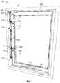
- FIG. 1is a perspective view of one example of a fenestration assembly.
- FIG. 2is a detailed perspective view showing the fenestration assembly of FIG. 1 with the panel in an open position.
- FIG. 3Ais a detailed perspective view showing the fenestration assembly of FIG. 1 in a secure configuration with a panel in a closed position and a locking mechanism is in a locked configuration.
- FIG. 3Bis a detailed perspective view showing the fenestration assembly of FIG. 1 in a first unsecure configuration with the panel in the open position and the locking mechanism is in an unlocked configuration.
- FIG. 3Cis a detailed perspective view showing the fenestration assembly of FIG. 1 in a second unsecure configuration with the panel in the closed position and the locking mechanism is in the unlocked configuration.
- FIG. 3Dis a detailed perspective view showing the fenestration assembly of FIG. 1 in a third unsecure configuration with the panel in the open position and the locking mechanism is in the locked configuration, and the locking mechanism blocks further closing of the panel.
- FIG. 4is a perspective view of the fenestration assembly of FIG. 1 with an example mechanism and monitoring cover coupled with the assembly.
- FIG. 5is a block diagram showing one example of a method for monitoring the status of a fenestration assembly.
- FIG. 1is a perspective view of one example of a fenestration assembly 100 (e.g., a window assembly, door assembly, or the like).
- the fenestration assembly 100includes a fenestration frame 110 and a panel 120 (e.g., a door, a sash, or the like).
- the fenestration frame 110is configured to be coupled to structures, including (but not limited to) a shed, a barn, a single-family residence, a multi-family residence, a municipal building, an office building, a warehouse, or the like.
- a casement windowis coupled to a wall of a residence.
- the panel 120optionally includes a pane of glass, and in some examples, the panel 120 is rotatable relative to the fenestration frame 110 (e.g., the panel 120 may rotate between an open position and a closed position). In another example, the panel 120 is configured to slide relative to the fenestration frame 110 .
- the fenestration assembly 100includes a panel operator 130 (e.g., a crank, a lever, a handle, a latch, or the like) configured to open and close the panel 120 .
- the panel operator 130is engaged with an operator linkage 140 .
- the operator linkage 140is coupled between the panel 120 and the fenestration frame 110 and facilitates the opening of the panel 120 (e.g., rotation, sliding or the like) relative to the fenestration frame 110 .
- the panel operator 130is moved (e.g., manipulated or rotated) by a user, automated drive mechanism or the like and the panel operator 130 engages with the operator linkage 130 to open or close the fenestration assembly 100 .
- the fenestration assembly 100includes one or more locking mechanisms.
- the fenestration assembly 100includes a first locking mechanism 150 A or a second locking mechanism 150 B (collectively referred to as “locking mechanisms 150 ”).
- the locking mechanism 150includes locked and unlocked configurations.
- the locked configurationthe panel 120 is fixed relative to the fenestration frame 110 (e.g., the panel 120 is held in place while closed and unable to rotate relative to the fenestration frame 110 ).
- the unlocked configurationthe panel 120 is not fixed relative to the fenestration frame 110 (e.g., the panel 120 is able to rotate, or translate, relative to the fenestration frame 110 , for instance with operation of the panel operator 130 ).
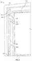
- FIG. 2is a detailed perspective view showing the fenestration assembly 100 of FIG. 1 with the panel 120 in an open position (the panel 120 is positioned in proximity to the frame 110 for illustration).
- the locking mechanism 150includes a first latch 151 and a first latch fastener 152 .
- the first latch 151selectively couples (e.g., engages) with the first latch fastener 152 to fix the panel 120 relative to the fenestration frame 110 .
- the first latch fastener 152is coupled with the panel 120
- the first latch 151is coupled with the fenestration frame 110 .
- the first latch 151is coupled with the first latch fastener 152 , and the coupling (e.g., engagement) of the first latch 151 with the first latch fastener 152 prevents the movement (e.g., rotation, sliding) of the panel 120 relative to the fenestration frame 110 .
- the first latch 151is disengaged from the first latch fastener 152 , and the panel 120 is free to move relative to the fenestration frame 110 (e.g., from closed to open, toward an open position wider than that shown in FIG. 2 or the like).
- the locking mechanism 150optionally includes a locking operator 155 (e.g., a lever, slider, handle, or the like).
- the locking operator 155is coupled with the first latch 151 , and movement (e.g., translation or manipulation) of the locking operator 155 couples or decouples the first latch 151 with the first latch fastener 152 to lock or unlock the locking mechanism 150 .
- the locking operator 155is rotatably coupled to a pivot point 250 .
- the locking operator 155is coupled to a latch linkage 260 .
- the locking operator 155is configured to move (e.g., rotate about the pivot point 250 ) and the movement of the locking operator 155 is transferred to the first latch 151 by the latch linkage 260 .
- the first latch 151is coupled to a tie bar 160 , and translation of the locking operator 155 is optionally transferred to the tie bar 160 by the latch linkage 260 and the first latch 151 .
- the locking operator 155is directly coupled with the tie bar 160 , for instance with a pin and groove assembly, and the tie bar 160 is coupled with the first latch 151 (and in some examples additional latches elsewhere on the fenestration assembly).
- the locking mechanism 150optionally includes a latch blade 210 .
- the latch blade 210includes a tapered portion 220 and includes a locking portion 230 .
- the tapered portion 220 of the latch blade 210is configured to bias a latch fastener (e.g., the first latch fastener 152 ) toward the locking portion 230 of the latch blade 210 .
- the first latch fastener 152optionally includes a pin 240 , and the tapered portion 220 biases the pin 240 of the first latch fastener 152 toward the locking portion 230 of the latch blade 210 .
- the latch blade 210facilitates the transition of the locking mechanism 150 into the locking configuration, for example by allowing the latch 151 to couple with the latch fastener 152 if the panel 120 is in a partially open position with the panel 120 in proximity to the frame 110 .
- the assistance in the transition provided by the latch blade 210in another example, facilitates the positioning of the panel 120 from the open position to the closed position.
- the locking mechanism 150optionally includes a tie bar 160 and the tie bar 160 is coupled to the locking operator 155 .
- the tie bar 160is configured to translate with respect to the fenestration frame 110 .
- the tie bar 160is configured to transmit the motion (e.g., rotation or translation) from the locking operator 155 to one or more of the first locking mechanism 150 A or the second locking mechanism 150 B.
- the locking operator 155is rotated, and the tie bar 160 correspondingly translates the first latch 151 (e.g., slides up or down with respect to the fenestration frame 110 ) to couple or decouple the first latch 151 with the first latch fastener 152 .
- the tie bar 160couples a second latch 157 with a second latch fastener 158 to couple or decouple these features at the second locking mechanism 150 B.
- the tie bar 160interconnects the first locking mechanism 150 A and the second locking mechanism 150 B to simultaneously change the configurations of (e.g., lock or unlock) the first locking mechanism 150 A and the second locking mechanism 150 B.
- the tie bar 160optionally includes a tie bar arm 165 .
- the tie bar arm 165projects away from at least one of the one or more locking mechanisms 150 , for instance the second locking mechanism 150 B.
- the tie bar arm 165projects from the second locking mechanism 150 B, and the tie bar arm 165 is positioned proximate a corner of the fenestration frame 110 .
- the tie bar arm 165translates (e.g., reciprocates) with respect to the locking mechanism 150 when the tie bar 160 translates (e.g., if the locking operator 155 is moved by a user).
- the fenestration assembly 100optionally includes a retaining bracket 170 .
- the retaining bracket 170defines a channel, and the channel is sized and shaped to receive the tie bar 160 .
- the retaining bracket 170is coupled with the fenestration frame 110 , and accordingly couples the tie bar 160 with the fenestration frame 110 .
- the tie bar 160is slidably coupled with the retaining bracket 160 (e.g., the channel), and the tie bar 160 is configured to translate with respect to the fenestration frame 110 .
- the tie bar arm 165translates (e.g., reciprocates) with respect to the retaining bracket 170 and the position of the tie bar arm 165 (e.g., an end portion of the tie bar arm 165 ) varies with respect to the retaining bracket 170 (or the fenestration frame 110 , for instance a corner of the fenestration frame 110 ).
- the fenestration assembly 100includes a status monitoring assembly 180 .
- the status monitoring assembly 180monitors a secure configuration (e.g., the panel 120 is in the closed position and the one or more locking mechanisms 150 are locked) and an unsecure configuration (including one or more unsecure configurations, such as the panel 120 is open or the one or more locking mechanisms 150 are unlocked) of the fenestration assembly 100 .
- the status monitoring assembly 180includes at least one sensor 182 and at least one sensor operator 184 .
- the sensor 182is coupled to one of the fenestration frame 110 or the panel 120 .
- the sensor operator 184is coupled to the other of the panel 120 or the fenestration frame 110 . As shown in FIG.
- the senor 182is coupled to the tie bar 160 (e.g., the tie bar arm 165 , or between the one or more locking mechanisms 150 ) and the sensor operator 184 is coupled with the panel 120 .
- the sensor operator 182is positioned remote relative to one or more of a latch (e.g., the second latch 157 in the example shown in FIG. 3A ) or a latch fastener (e.g., the second latch fastener 158 ).
- the second latch 157is coupled to the fenestration frame 110
- the second latch fastener 158is coupled to the panel 120
- the sensor operator 184is coupled to the panel 120 remote relative from (e.g., spaced from) the second latch fastener 158 .
- the sensor 182detects the presence of the sensor operator 184 (e.g., a magnet, a mechanical contact, an electrical contact, or the like). In an example, the sensor 182 detects the sensor operator 184 positioned proximate the sensor operator 184 .
- the sensor 182includes an electrical switch, and if the sensor operator 184 is positioned proximate the sensor 182 (e.g., the panel 120 is closed and locked), the electrical switch is closed and one or more of current or a change in resistance or potential are sensed. If the sensor operator 184 is remote from the sensor 182 , the electrical switch is open and the sensor accordingly fails to detect the closed and locked panel 120 .
- the sensor 182 and the sensor operator 184are coupled to the fenestration assembly 100 to facilitate the monitoring of the secure and unsecure configurations of the fenestration assembly 100 .
- the sensor 182detects the sensor operator 184 if the panel 120 is in the closed position.
- the sensor 182detects the sensor operator 184 if a latch (e.g., the first latch 151 ) is coupled with a latch fastener (e.g., the first latch fastener 152 ).
- the sensor 182detects the sensor operator 184 because the fenestration assembly 100 is in the closed position and the latch is coupled with the latch fastener.
- the status monitoring assembly 180is optionally configured to report an indication (e.g., an LED is activated, a mechanical flag or indicia is triggered, an electrical or electromagnetic signal) of the secure configuration if the sensor operator 184 is detected by the sensor 182 . Additionally, and in some examples, the status monitoring assembly 180 is configured to report an indication of the unsecure configuration if the sensor operator 184 is undetected by the sensor 182 .
- an indicatione.g., an LED is activated, a mechanical flag or indicia is triggered, an electrical or electromagnetic signal
- the fenestration assembly 100optionally includes a module 200 , and the module 200 provides a connection (e.g., one or more of wired or wireless connections) between the sensor 182 and one or more additional components, including (but not limited to) home networks, home servers, applications (e.g., cellular phone apps or desktop programs), computers, or the like (each included as optional components of the fenestration status monitoring assembly 180 ).
- the module 200includes a transceiver (e.g., one or more of a receiver or a transmitter), a power supply (e.g., a battery or transformer), a Power over Ethernet interface, a network interface (e.g., an RJ-45 port) or the like.
- the module 200is optionally concealed within one or more of the fenestration frame 110 or the panel 120 .
- components of the module 200e.g., a power supply and a transceiver
- the unitsare separately coupled to (including concealed within) the fenestration frame 110 or the panel 120 .
- FIG. 3Ais a detailed perspective view showing the fenestration assembly 100 of FIG. 1 in a secure configuration with the panel 120 in the closed position and the locking mechanism 150 in the locked configuration.
- the example assembly 100includes the first locking assembly 150 A and the second locking assembly 150 B in the locked configuration, the first latch 151 is coupled with the first latch fastener 152 , and the second latch 157 is coupled with the second latch fastener 158 of the respective assemblies 150 A, B. Accordingly, the panel 120 is held static in the closed position relative to the fenestration frame 110 .
- the senor 182is coupled to the tie bar arm 165 and the sensor operator 184 is coupled to the panel 120 .
- the sensor 182With the window assembly 100 in the secure configuration, the sensor 182 is positioned proximate (e.g., adjacent to, close to, positioned near, or the like) the sensor operator 184 , and the sensor 182 detects the presence of the sensor operator 184 . Accordingly, the status monitoring assembly 180 detects that the fenestration assembly 100 is in the secure configuration. As described herein, the detected secure configuration is optionally reported (e.g., indicated).
- the senor 182is configured to detect the sensor operator 184 only if the panel 120 is in the closed position and a latch (e.g., the second latch 157 ) is coupled with a latch fastener (e.g., the second latch fastener 158 ). In this configuration the sensor operator 184 is in proximity to the sensor 182 and thereby detected. As a result, the sensor 182 is configured to detect the sensor operator 184 only if the fenestration assembly 100 is in the secure configuration (e.g., closed and locked).
- a latche.g., the second latch 157
- a latch fastenere.g., the second latch fastener 158
- the fenestration assembly 100either open, unlocked or open and unlocked the sensor 182 and the sensor operator 184 are not in proximity to each other (as described herein) and accordingly the status monitoring assembly 100 does not detect a secure configuration, and optionally indicates (e.g., reports) an unsecure configuration.
- FIG. 3Bis a detailed perspective view showing the fenestration assembly 100 of FIG. 1 in an example first unsecure configuration with the panel 120 in the open position and the locking mechanism 150 in the unlocked configuration.
- the first latch 151is decoupled from the first latch fastener 152
- the second latch 157is decoupled from the second latch fastener 158 .
- the panel 120is accordingly not locked and is free to move (e.g., able to rotate or slide between the open and closed positions).
- the sensor operator 184is remote relative to (e.g., not adjacent to, not close to, or positioned away from) the sensor 182 . Because the panel 120 is in the open position, the sensor 182 fails to detect the sensor operator 184 , and the status monitoring assembly 180 indicates the fenestration assembly 100 is in an unsecure configuration (including a failure to indicate a second configuration). In another example, the status monitoring assembly 180 reports (e.g., provides, transmits or the like) an indication of the unsecure configuration, such as a signal or failure to provide a signal (including no signal).
- FIG. 3Cis a detailed perspective view showing the fenestration assembly 100 of FIG. 1 in a second unsecure configuration with the panel 120 in the closed position and the locking mechanism 150 is in the unlocked configuration.
- the first locking assembly 150 A and the second locking assembly 150 Bare in the unlocked configuration, the first latch 151 is decoupled from the first latch fastener 152 , and the second latch 157 is decoupled from the second latch fastener 158 . Accordingly, the panel 120 is not fixed relative to the fenestration frame 110 .
- the tie bar 160is coupled with the locking operator 155 , and the tie bar 160 transmits motion (e.g., translation or movement) of the locking operator 155 to each of the one or more locking mechanisms 150 (e.g., the first locking mechanism 150 A and the second locking mechanism 150 B).
- the tie bar arm 165projects away from at least one of the locking mechanisms 150 , and the sensor 182 (or the sensor operator 184 ) is coupled to the tie bar arm 166 . Accordingly, the tie bar arm 165 positions the sensor 182 (or the sensor operator 184 ) remote relative to one or more of the locking mechanisms 150 .
- the senor 182is repositionable relative to the fenestration frame 110 (and/or the sensor operator 184 ).
- the tie bar 160is configured to translate with respect to the fenestration frame 110 (or the retaining bracket 170 ).
- the tie bar arm 165correspondingly translates with respect to the fenestration frame 110 .
- the sensor 182 (or the sensor operator 184 )is optionally coupled to the tie bar arm 165 , and accordingly, the sensor 182 translates with respect to the fenestration frame 110 if the locking operator 155 is manipulated.
- the translation of the sensor 182repositions the sensor 182 relative to the fenestration frame 110 or other components of the fenestration assembly 100 (e.g., the first latch fastener 152 , the retaining bracket 170 , or the sensor operator 184 ).
- the sensor 182is positioned proximate to the second latch fastener 158 if the locking mechanism 150 is in the unlocked configuration.
- the sensor 182is positioned remote to the second latch fastener 158 if the locking mechanism 150 is in the locked configuration.
- the sensor operator 184is positioned remote relative to the sensor 182 because the sensor 182 is positioned relatively downward (e.g., toward the retaining bracket 170 ) while the locking mechanism 150 is in the unlocked configuration. If the locking mechanism 150 is in the unlocked configuration, the sensor 182 does not detect the sensor operator 184 . Because the sensor 182 does not detect the sensor operator 184 , the status monitoring assembly 180 reports a signal (including no signal) indicating that the fenestration assembly 100 is in an unsecure configuration, including (but not limited to) the first unsecure configuration shown in FIG. 3B .
- the locking operator 155is moved (e.g., manipulated by a user) and the locking mechanism 150 is transitioned to the locked configuration.
- the tie bar 160(and the tie bar arm 165 ) translates with respect to the fenestration frame 110 (e.g., away from the retaining bracket 170 ).
- the translation of the tie bar 160positions the sensor operator 182 proximate relative to the sensor 182 , and in the locked configuration, the sensor 182 detects the sensor operator 184 .
- the senor 182fails to detect the sensor operator 184 , and the status monitoring assembly 180 reports (e.g., provides) an indication (e.g., an electrical signal) indicating that the fenestration assembly 100 is in an unsecure configuration, including (but not limited to) the second unsecure configuration shown in FIG. 3C .
- an indicatione.g., an electrical signal
- FIG. 3Dis a detailed perspective view showing the fenestration assembly 100 of FIG. 1 in a third unsecure configuration with the panel 120 in the open position and the locking mechanism is in the locked configuration, and the locking mechanism 150 blocks further closing of the panel 120 .
- the locking mechanism 150includes a blocking configuration, and the locking mechanism 150 prevents the positioning of the panel 120 in the closed position.
- the first latch 151is not coupled with the first latch fastener 152 . Instead, the first latch fastener 152 is engaged with first latch 151 , and the engagement of the first latch fastener 152 with the first latch 151 prevents the positioning of the panel 120 in the closed position.
- the locking mechanism 150is in the locking configuration, the first latch 151 is aligned with the first latch fastener 152 , and the first latch 151 intercepts the first latch fastener 152 with movement (e.g., rotation) of the panel 120 toward the closed position.
- the first latch 151prevents positioning of the panel 120 in the closed position.
- the sensor operator 184is remote relative to the sensor 182 because the first latch 151 is intercepting the first latch fastener 152 and the status monitoring assembly 100 reports an unsecure configuration of the fenestration assembly 100 , including (but not limited to) the third unsecure configuration shown in FIG. 3D .
- FIG. 4is a perspective view of the fenestration assembly 100 of FIG. 1 with mechanism and monitoring cover 400 coupled with the assembly 100 .
- the mechanism and monitoring cover 400is a concealing facie that is coupled to the fenestration assembly 100 to, among other things, improve the aesthetic appeal of the fenestration assembly 100 .
- the mechanism and monitoring cover 300conceals (e.g., hides, obscures, or the like) components of the locking mechanism 150 and the status monitoring assembly 180 , including (but not limited to) the first locking mechanism 150 A, the second locking mechanism 150 B, the tie bar 160 , the tie bar arm 165 , the sensor 182 , the sensor operator 184 , and the module 200 .
- the mechanism and monitoring cover 400defines a recess to allow the locking operator 155 to be moved (e.g., manipulated by a user) while the remaining components of the locking mechanism 150 are concealed by the mechanism and monitoring cover 400 .
- the mechanism and monitoring cover 400matches the finish of the remainder of the fenestration assembly 100 (e.g., wood grain, paint, vinyl, another polymer, or the like).
- FIG. 5is a block diagram showing one example of a method 500 for monitoring a status of a fenestration assembly 100 .
- the method 500reference is made to one or more components, features, functions and operations previously described herein. Where convenient, reference is made to the components, features, operations and the like with reference numerals. The reference numerals provided are exemplary and are not exclusive. For instance, components, features, functions, operations and the like described in the method 500 include, but are not limited to, the corresponding numbered elements provided herein and other corresponding elements described herein (both numbered and unnumbered) as well as their equivalents.
- At 502at least one panel 120 is moved between an open position and a closed position relative to a fenestration frame 110 (see FIGS. 3A-3B ). For instance, the panel 120 is rotated relative to the fenestration frame 110 .
- the method 500includes moving at least one latch (e.g., the first latch 151 and/or the second latch 157 , shown in FIG. 1 ) between coupled and decoupled positions relative to a latch fastener, for instance the first latch fastener 152 or the second latch fastener 158 .
- a latch fastenerfor instance the first latch fastener 152 or the second latch fastener 158 .
- an operatore.g., the locking operator 155 of FIGS. 3A-3D
- the movement of the operatoris transmitted to the at least one latch, including (but not limited to) transmitting the motion with a tie bar 160 .
- the at least one latchmoves according to (e.g., corresponding with) the movement of the operator.
- the secure and unsecure configurations of the fenestration assembly 100are monitored with a status monitoring assembly 180 including a sensor 182 and a sensor operator 184 .
- the sensor 182detects the sensor operator 184 , and optionally transmits a signal (or no signal) to facilitate the reporting of the secure and unsecure configurations of the fenestration assembly 100 .
- monitoring the configuration of the fenestration assembly 100includes failing to detect the sensor operator 184 with the sensor 182 if at least one of the panel 120 is in the open position or the latch (e.g., the first latch 151 , shown in FIG. 2 ) is decoupled from the latch fastener (e.g., the first latch fastener 152 , shown in FIG. 2 ).
- the latche.g., the first latch 151 , shown in FIG. 2
- the latch fastenere.g., the first latch fastener 152 , shown in FIG. 2
- monitoring the configuration of the fenestration assembly 100includes detecting the sensor operator 184 with the sensor 182 if both the at least one panel 120 is in the closed position and the latch (e.g., the second latch 157 , shown in FIG. 1 ) is coupled with the latch fastener (e.g., the second latch fastener 158 , shown in FIG. 1 ).
- the sensor 182is coupled with the tie bar 160 , the sensor 182 moves with the tie bar 160 .
- the sensor 182is moved into proximity with the sensor operator 184 , and the sensor 182 detects the sensor operator 184 .
- the sensor 182is moved into proximity with the sensor operator 184 , and the sensor 182 is moved away from the latch fastener (e.g., the second latch fastener 158 ).
- the sensor operator 184is detected by moving the at least one panel 120 into the closed position.
- the sensor operator 184is moved into proximity with the sensor 182 with movement of the at least one panel 200 .
- the sensor 182is moved into proximity with the sensor operator 184 with movement of the at least one latch (e.g., the first latch 151 ).
- the sensor 182is coupled with the tie bar 160 , the tie bar 160 is configured to move the at least one latch, and the sensor 182 is moved with the tie bar 160 and the at least one latch.
- a secure configuration notificationis provided if the sensor operator 184 is detected by the sensor 182 .
- the module 200is in communication with the sensor 182 (e.g., hard-wired or wirelessly), and the module 200 provides the secure notification to a user, including (but not limited to) an electronic device (e.g., a cellular phone, a tablet computer, a desktop computer, a home automation display, or the like).
- an electronic devicee.g., a cellular phone, a tablet computer, a desktop computer, a home automation display, or the like.
- Example 1can include subject matter, such as a fenestration assembly configured for status monitoring, the fenestration assembly comprising: a fenestration frame; at least one panel rotatably coupled with the fenestration frame between open and closed positions; a locking mechanism coupled with the fenestration frame and the panel, the locking mechanism includes at least one latch and at least one latch fastener, one of the latch or latch fastener is coupled with the fenestration frame and the other of the latch fastener or latch is coupled with the panel; wherein the fenestration assembly includes secure and unsecure configurations, in the secure configuration the panel is in the closed position and the latch is coupled with the latch fastener, and in the unsecure configuration one or more of the panel is in the open position or the latch is decoupled from the latch fastener; and a status monitoring assembly configured to monitor secure and unsecure configurations of the fenestration assembly, the status monitoring assembly includes: a sensor operator coupled with one of the fenestration frame or the panel,
- Example 2can include, or can optionally be combined with the subject matter of Example 1, to optionally include wherein the status monitoring assembly is configured to report the secure configuration with the sensor operator detected by the sensor, and the status monitoring assembly is configured to report the unsecure configuration with the sensor operator undetected by the sensor.
- Example 3can include, or can optionally be combined with the subject matter of one or any combination of Examples 1 or 2 to optionally include wherein the latch includes a latch blade having a tapered portion and a locking portion, the tapered portion is configured to bias the latch fastener toward the locking portion.
- Example 4can include, or can optionally be combined with the subject matter of one or any combination of Examples 1-3 to optionally include wherein the sensor is configured to detect the sensor operator only if the panel is in the closed position and the latch is coupled with the latch fastener.
- Example 5can include, or can optionally be combined with the subject matter of one or any combination of Examples 1-4 to optionally include wherein the sensor operator is selected from the group consisting of a magnet, a mechanical contact or an electrical contact and the sensor is selected from the group consisting of a magnetic sensor, a mechanical switch or an electrical switch.
- Example 6can include, or can optionally be combined with the subject matter of Examples 1-5 to optionally include wherein the locking mechanism includes: an operator, a tie bar coupled between the operator and the latch, and wherein movement of the operator between locked and unlocked positions moves the tie bar and the latch between corresponding locked and unlocked positions.
- the locking mechanismincludes: an operator, a tie bar coupled between the operator and the latch, and wherein movement of the operator between locked and unlocked positions moves the tie bar and the latch between corresponding locked and unlocked positions.
- Example 7can include, or can optionally be combined with the subject matter of Examples 1-6 to optionally include wherein each of the operator, tie bar and the latch are coupled with the fenestration frame, and the latch fastener is coupled with the panel.
- Example 8can include, or can optionally be combined with the subject matter of Examples 1-7 to optionally include wherein the sensor is coupled with the tie bar, and the sensor operator is coupled with the panel.
- Example 9can include, or can optionally be combined with the subject matter of Examples 1-8 to optionally include wherein the sensor is remote relative to the latch fastener with the latch in a locked position, and the sensor is more proximate to the latch fastener in an unlocked position than in the locked position.
- Example 10can include, or can optionally be combined with the subject matter of Examples 1-9 to optionally include wherein the sensor operator is remote relative to the latch fastener and the latch.
- Example 11can include, or can optionally be combined with the subject matter of Examples 1-10 to optionally include a fenestration assembly configured for status monitoring, the fenestration assembly comprising: a fenestration frame; at least one panel rotatably coupled with the fenestration frame between open and closed positions; a locking mechanism coupled with the fenestration frame and the panel, the locking mechanism includes: at least one latch fastener, at least one latch, an operator, a tie bar coupled between the operator and the latch, and wherein movement of the operator between locked and unlocked positions moves the tie bar and the latch between corresponding locked and unlocked positions; and a status monitoring assembly configured to monitor secure and unsecure configurations of the fenestration assembly, the status monitoring assembly includes: a sensor operator coupled with one of the fenestration frame or the panel, and a sensor coupled with the other of the panel or the fenestration frame, and the sensor is configured to detect the sensor operator if the sash is in the closed position and the latch is coupled with the
- Example 12can include, or can optionally be combined with the subject matter of Examples 1-11 to optionally include wherein each of the operator, tie bar and the latch are coupled with the fenestration frame, and the latch fastener is coupled with the panel.
- Example 13can include, or can optionally be combined with the subject matter of Examples 1-12 to optionally include wherein the sensor is coupled with the tie bar, and the sensor operator is coupled with the panel.
- Example 14can include, or can optionally be combined with the subject matter of Examples 1-13 to optionally include wherein the sensor is remote relative to the latch fastener with the latch in the locked position, and the sensor is more proximate to the latch fastener in the unlocked position than in the locked position.
- Example 15can include, or can optionally be combined with the subject matter of Examples 1-14 to optionally include wherein the sensor operator is remote relative to the latch fastener and the latch.
- Example 16can include, or can optionally be combined with the subject matter of Examples 1-15 to optionally include wherein the at least one latch includes first and second latches, and the tie bar couples each of the first and second latches with the operator.
- Example 17can include, or can optionally be combined with the subject matter of Examples 1-16 to optionally include wherein the locking mechanism includes a blocking configuration, and in the blocking configuration with the panel in the open position and the latch in the locked position the latch is aligned with the latch fastener, the latch intercepts the latch fastener with movement of the panel toward the closed position and prevents positioning of the panel in the closed position, and the sensor operator is held remote from the sensor with the latch intercepting the latch fastener.
- the locking mechanismincludes a blocking configuration, and in the blocking configuration with the panel in the open position and the latch in the locked position the latch is aligned with the latch fastener, the latch intercepts the latch fastener with movement of the panel toward the closed position and prevents positioning of the panel in the closed position, and the sensor operator is held remote from the sensor with the latch intercepting the latch fastener.
- Example 18can include, or can optionally be combined with the subject matter of Examples 1-17 to optionally include wherein the status monitoring assembly is configured to report a secure configuration with the sensor operator detected by the sensor, and the status monitoring assembly is configured to report an unsecure configuration with the sensor operator undetected by the sensor.
- Example 19can include, or can optionally be combined with the subject matter of Examples 1-18 to optionally include wherein the latch fastener includes a pin, and the latch includes a latch blade having a tapered portion and a locking portion, the tapered portion is configured to bias the pin toward the locking portion.
- the latch fastenerincludes a pin
- the latchincludes a latch blade having a tapered portion and a locking portion, the tapered portion is configured to bias the pin toward the locking portion.
- Example 20can include, or can optionally be combined with the subject matter of Examples 1-19 to optionally include wherein the sensor is configured to detect the sensor operator only if the sash is in the closed position and the latch is in the locked position.
- Example 21can include, or can optionally be combined with the subject matter of Examples 1-20 to optionally include wherein the sensor operator includes one or more of a magnet, a mechanical contact or an electrical contact, and the sensor includes one or more of a magnetic sensor, a mechanical switch or an electrical switch.
- Example 22can include, or can optionally be combined with the subject matter of Examples 1-21 to optionally include a power source in electrical communication with the sensor, and the power source is concealed within one or more of the panel or the fenestration frame.
- Example 23can include, or can optionally be combined with the subject matter of Examples 1-22 to optionally include a transceiver in electrical communication with the sensor, and the transceiver is concealed within one or more of the panel or the fenestration frame.
- Example 24can include, or can optionally be combined with the subject matter of Examples 1-23 to optionally include a method for monitoring a status of a fenestration assembly comprising: moving at least one panel between an open position and a closed position relative to a fenestration frame; moving at least one latch between coupled and decoupled positions relative to a latch fastener; monitoring secure and unsecure configurations of the fenestration assembly with a status monitoring assembly including a sensor and a sensor operator, monitoring including: failing to detect the sensor operator with the sensor if at least one of the panel is in the open position or the latch is decoupled from the latch fastener, and detecting the sensor operator with the sensor if both the at least one panel is in the closed position and the latch is coupled with the latch fastener; and providing a secure configuration notification if the sensor operator is detected by the sensor.
- Example 25can include, or can optionally be combined with the subject matter of Examples 1-24 to optionally include wherein moving the at least one panel includes rotating the at least one panel relative to the fenestration frame.
- Example 26can include, or can optionally be combined with the subject matter of Examples 1-25 to optionally include wherein moving the at least one latch between coupled and decoupled positions includes: moving an operator, transmitting movement from the operator to the at least one latch with a tie bar, and moving the at least one latch according to movement of the operator.
- Example 27can include, or can optionally be combined with the subject matter of Examples 1-26 to optionally include wherein detecting the sensor operator with the sensor includes moving the sensor into proximity with the sensor operator, the sensor is coupled with the tie bar and moves with the tie bar.
- Example 28can include, or can optionally be combined with the subject matter of Examples 1-27 to optionally include wherein detecting the sensor operator with the sensor includes: moving the at least one panel into the closed position and moving the sensor operator into proximity with the sensor with movement of the at least one panel, and moving the sensor into proximity with the sensor operator with movement of the at least one latch.
- Example 29can include, or can optionally be combined with the subject matter of Examples 1-28 to optionally include wherein moving the sensor into proximity with the sensor operator with movement of the least one latch includes moving the sensor with a tie bar configured to move the at least one latch, the sensor coupled with the tie bar.
- Example 30can include, or can optionally be combined with the subject matter of Examples 1-29 to optionally include wherein detecting the sensor operator with the sensor includes: moving the sensor into proximity with the sensor operator, and moving the sensor away from the latch fastener.
- the terms “a” or “an”are used, as is common in patent documents, to include one or more than one, independent of any other instances or usages of “at least one” or “one or more.”
- the term “or”is used to refer to a nonexclusive or, such that “A or B” includes “A but not B,” “B but not A,” and “A and B,” unless otherwise indicated.
- Geometric termssuch as “parallel”, “perpendicular”, “round”, or “square”, are not intended to require absolute mathematical precision, unless the context indicates otherwise. Instead, such geometric terms allow for variations due to manufacturing or equivalent functions. For example, if an element is described as “round” or “generally round,” a component that is not precisely circular (e.g., one that is slightly oblong or is a many-sided polygon) is still encompassed by this description.
- Method examples described hereincan be machine or computer-implemented at least in part. Some examples can include a computer-readable medium or machine-readable medium encoded with instructions operable to configure an electronic device to perform methods as described in the above examples.
- An implementation of such methodscan include code, such as microcode, assembly language code, a higher-level language code, or the like. Such code can include computer readable instructions for performing various methods. The code may form portions of computer program products. Further, in an example, the code can be tangibly stored on one or more volatile, non-transitory, or non-volatile tangible computer-readable media, such as during execution or at other times.
- Examples of these tangible computer-readable mediacan include, but are not limited to, hard disks, removable magnetic disks, removable optical disks (e.g., compact disks and digital video disks), magnetic cassettes, memory cards or sticks, random access memories (RAMs), read only memories (ROMs), and the like.
Landscapes
- Physics & Mathematics (AREA)
- General Physics & Mathematics (AREA)
- Engineering & Computer Science (AREA)
- Computer Security & Cryptography (AREA)
- Business, Economics & Management (AREA)
- Emergency Management (AREA)
- Emergency Alarm Devices (AREA)
- Investigating Or Analyzing Materials By The Use Of Electric Means (AREA)
- Investigating Or Analysing Biological Materials (AREA)
Abstract
Description
Claims (30)
Priority Applications (2)
| Application Number | Priority Date | Filing Date | Title |
|---|---|---|---|
| US16/035,341US10930124B2 (en) | 2017-07-13 | 2018-07-13 | Integrated fenestration status monitoring systems and methods for the same |
| US17/167,815US11798383B2 (en) | 2017-07-13 | 2021-02-04 | Integrated fenestration status monitoring systems and methods for the same |
Applications Claiming Priority (2)
| Application Number | Priority Date | Filing Date | Title |
|---|---|---|---|
| US201762532208P | 2017-07-13 | 2017-07-13 | |
| US16/035,341US10930124B2 (en) | 2017-07-13 | 2018-07-13 | Integrated fenestration status monitoring systems and methods for the same |
Related Child Applications (1)
| Application Number | Title | Priority Date | Filing Date |
|---|---|---|---|
| US17/167,815ContinuationUS11798383B2 (en) | 2017-07-13 | 2021-02-04 | Integrated fenestration status monitoring systems and methods for the same |
Publications (2)
| Publication Number | Publication Date |
|---|---|
| US20190019382A1 US20190019382A1 (en) | 2019-01-17 |
| US10930124B2true US10930124B2 (en) | 2021-02-23 |
Family
ID=64999045
Family Applications (2)
| Application Number | Title | Priority Date | Filing Date |
|---|---|---|---|
| US16/035,341ActiveUS10930124B2 (en) | 2017-07-13 | 2018-07-13 | Integrated fenestration status monitoring systems and methods for the same |
| US17/167,815ActiveUS11798383B2 (en) | 2017-07-13 | 2021-02-04 | Integrated fenestration status monitoring systems and methods for the same |
Family Applications After (1)
| Application Number | Title | Priority Date | Filing Date |
|---|---|---|---|
| US17/167,815ActiveUS11798383B2 (en) | 2017-07-13 | 2021-02-04 | Integrated fenestration status monitoring systems and methods for the same |
Country Status (2)
| Country | Link |
|---|---|
| US (2) | US10930124B2 (en) |
| CA (1) | CA3011471C (en) |
Cited By (8)
| Publication number | Priority date | Publication date | Assignee | Title |
|---|---|---|---|---|
| US11015368B2 (en) | 2016-02-12 | 2021-05-25 | Marvin Lumber And Cedar Company, Llc | Integrated fenestration status monitoring system and methods for the same |
| USD930465S1 (en)* | 2019-09-17 | 2021-09-14 | Truth Hardware Corporation | Casement window operator cover and folding handle |
| US11365561B2 (en) | 2017-01-17 | 2022-06-21 | Marvin Lumber And Cedar Company, Llc | Fenestration assembly operation hardware and methods for same |
| US20220341229A1 (en)* | 2019-09-17 | 2022-10-27 | Mighton Products Limited | Casement window locking bar sensor |
| USD980708S1 (en)* | 2021-03-02 | 2023-03-14 | Amesbury Truth Corporation | Casement window operator handle and cover |
| US20230250685A1 (en)* | 2022-02-10 | 2023-08-10 | Marvin Lumber And Cedar Company, Llc D/B/A Marvin Windows And Doors | Fenestration automated operating system and methods for same |
| US11798383B2 (en) | 2017-07-13 | 2023-10-24 | Marvin Lomber and Cedar Company | Integrated fenestration status monitoring systems and methods for the same |
| US12331576B2 (en) | 2022-02-01 | 2025-06-17 | Pella Corporation | Powered pivoting fenestration unit and associated systems and methods |
Citations (98)
| Publication number | Priority date | Publication date | Assignee | Title |
|---|---|---|---|---|
| US398039A (en) | 1889-02-19 | Henry abel flatman and james seed | ||
| US660438A (en) | 1900-03-22 | 1900-10-23 | Abby A Vallette | Window-sash. |
| US937348A (en) | 1909-08-20 | 1909-10-19 | George D Wheelock | Sash-fastener. |
| US1434371A (en) | 1919-08-23 | 1922-11-07 | Crompton Edwin | Lock or latch |
| US2104134A (en) | 1937-01-29 | 1938-01-04 | Mellebrand Ferdinand | Window latch |
| US2274711A (en) | 1940-08-02 | 1942-03-03 | Chicago Forging & Mfg Co | Hood latch |
| US2545645A (en) | 1945-11-07 | 1951-03-20 | William M Blakely | Window lock |
| US2778326A (en) | 1954-09-10 | 1957-01-22 | Guzik Casimir | Panic latch for refrigerator doors and the like |
| US2883225A (en) | 1953-10-16 | 1959-04-21 | Ervin T Akehurst | Detent mechanism for double hung sash window |
| US2967595A (en) | 1958-02-05 | 1961-01-10 | Alumatic Corp Of America | Window sash rack construction |
| US3525830A (en) | 1967-03-14 | 1970-08-25 | Gen Alarm Corp | Lock switch devices |
| US3641540A (en) | 1970-03-30 | 1972-02-08 | Joel L Cutler | Wireless alarm system |
| US4346372A (en) | 1980-09-22 | 1982-08-24 | Truth Incorporated | Window operator with switch to operate a burglar alarm |
| US4351288A (en) | 1981-06-17 | 1982-09-28 | White Consolidated Industries, Inc. | Oven door latch |
| US4465997A (en) | 1981-01-26 | 1984-08-14 | Security Network International, Inc. | Exterior mounted door and window alarm switch |
| US4497135A (en) | 1982-11-15 | 1985-02-05 | Truth Incorporated | Automatic operator and locking mechanism for a closure |
| US4624073A (en) | 1985-11-15 | 1986-11-25 | Traco | Locking tilt window sash and lock therefor |
| US4639021A (en) | 1985-11-25 | 1987-01-27 | Hope Jimmie L | Door lock |
| US5004961A (en) | 1988-12-16 | 1991-04-02 | Truth Incorporated | Window operator control |
| US5006766A (en) | 1989-08-14 | 1991-04-09 | Rolscreen Company | Window operator for manually or electrically motorized actuation of a mechanical window drive system |
| US5090750A (en) | 1991-01-03 | 1992-02-25 | Fixfabriken Ab | Locking mechanism for sash type windows |
| US5226256A (en) | 1989-05-12 | 1993-07-13 | Aug. Winkhaus Gmbh & Co., Kg | Window system for a building |
| US5301989A (en) | 1993-03-09 | 1994-04-12 | Truth Hardware Corporation | Tilt lock for double-hung windows |
| US5311168A (en) | 1992-09-10 | 1994-05-10 | Pease Industries, Inc. | Lock set with self-contained door alarm and annunciator system |
| US5355059A (en) | 1993-02-18 | 1994-10-11 | Truth Hardware Corporation | Electronic switch assembly for motorized window system |
| US5382060A (en) | 1993-01-11 | 1995-01-17 | Amerock Corporation | Latching apparatus for double doors |
| US5398447A (en) | 1994-02-28 | 1995-03-21 | Morse; Allen D. | Centrally located tilt-in window handle |
| US5437173A (en) | 1993-02-18 | 1995-08-01 | Truth Division Of Spx Corporation | Window lock with indicator |
| US5449987A (en) | 1993-09-24 | 1995-09-12 | Truth Division Of Spx Corporation | Window operator control |
| US5592781A (en) | 1995-05-19 | 1997-01-14 | Mauro; Gerald D. | Rotating tilt latch |
| US5595409A (en) | 1994-07-05 | 1997-01-21 | Anderson Corporation | Gliding door latch assembly |
| US5595075A (en) | 1995-01-31 | 1997-01-21 | Chen; Mike | Lock and alarm means lockable on window and door rail |
| US5653485A (en) | 1995-03-27 | 1997-08-05 | Andersen Corporation | Single actuation sash lock |
| US5712621A (en) | 1996-06-06 | 1998-01-27 | Andersen; James D. | Security system with variable inductance sensor |
| US5791700A (en) | 1996-06-07 | 1998-08-11 | Winchester Industries, Inc. | Locking system for a window |
| GB2333555A (en) | 1998-01-24 | 1999-07-28 | Alex Cuthbertson | Sash window latch |
| US5992907A (en) | 1998-04-27 | 1999-11-30 | Truth Hardware Corporation | Lock and tilt latch for sliding windows |
| US6141913A (en) | 1999-06-08 | 2000-11-07 | Marvin Lumber And Cedar Company | Window sash position maintainer |
| US6176041B1 (en) | 1999-07-29 | 2001-01-23 | James Wilford Roberts | Casement assembly and a latch mechanism therefor |
| US6212923B1 (en) | 1998-01-02 | 2001-04-10 | Sargent & Greenleaf, Inc. | Lock including means for sensing position of bolt and for indicating whether or not bolt is extended from lock case |
| US20020116874A1 (en) | 2000-10-20 | 2002-08-29 | Marshik Gary J. | Methods and apparatus for a single lever tilt lock latch window |
| US20030084614A1 (en) | 2001-11-07 | 2003-05-08 | Dean Pettit | Integrated tilt/sash lock assembly |
| US6588150B1 (en) | 1999-11-23 | 2003-07-08 | Marvin Lumber And Cedar Company | Rotatable actuator for latches of a window sash |
| US6615629B2 (en) | 2001-01-19 | 2003-09-09 | Schlage Lock Company | Interconnected lock with door status sensor |
| US6669242B2 (en) | 2001-06-20 | 2003-12-30 | Assa Abloy Financial Services Ab | Latch device |
| US6778086B2 (en) | 2002-05-02 | 2004-08-17 | Gerald Angelo Morrone | Open window security lock |
| US20040168370A1 (en) | 2002-11-07 | 2004-09-02 | Dean Pettit | Integrated tilt/sash lock assembly |
| US20040195843A1 (en) | 2003-04-01 | 2004-10-07 | Anthony Rotondi | Window fastener |
| US20040200150A1 (en) | 2002-05-03 | 2004-10-14 | Andersen Corporation | Tilt latch mechanism for hung windows |
| US6871885B2 (en) | 2001-04-05 | 2005-03-29 | 420820 Ontario Limited | Combination cam lock/tilt latch and latching block therefor with added security feature |
| US20050140150A1 (en) | 2003-08-18 | 2005-06-30 | Matthew Hall | Load floor latch |
| US20060033343A1 (en) | 2004-07-29 | 2006-02-16 | Xiangui Xu | Latching apparatus for sliding closure members |
| US7042353B2 (en) | 2003-02-03 | 2006-05-09 | Ingrid, Inc. | Cordless telephone system |
| US7068162B2 (en) | 2003-06-24 | 2006-06-27 | Alan James Maple | Compartment security system |
| US7079020B2 (en) | 2003-02-03 | 2006-07-18 | Ingrid, Inc. | Multi-controller security network |
| US20060244270A1 (en) | 2005-04-28 | 2006-11-02 | Continental Investment Partners Llc | Automatic window tilt latch mechanism |
| US7158029B1 (en) | 2004-03-26 | 2007-01-02 | Elva Lee Martyn | Electronic security system |
| US7165791B2 (en) | 2004-08-18 | 2007-01-23 | Jacob Rebel | Positive action fenestration lock |
| US20070046036A1 (en) | 2005-09-01 | 2007-03-01 | Kinsey Bruce F | Slidable and rotatable lock for a window or door |
| US7227463B2 (en) | 2001-05-24 | 2007-06-05 | Merrell Daniel B | Alarm systems, alarm system operating methods, and alarm extension devices |
| US20070194914A1 (en) | 2005-11-22 | 2007-08-23 | Gates Tell A | RFID perimeter alarm monitoring system |
| US20070209281A1 (en) | 2001-11-07 | 2007-09-13 | Flory Edward C | Integrated tilt/sash lock assembly |
| US20070262848A1 (en) | 2006-05-11 | 2007-11-15 | Viktors Berstis | Key Fob and System for Indicating the Lock Status of a Door Lock |
| US20080000162A1 (en)* | 2006-06-09 | 2008-01-03 | James Patrick Zayac | Sash reinforcement for an operator window |
| US7322619B2 (en) | 2005-01-26 | 2008-01-29 | Truth Hardware Corporation | Integrated lock and tilt-latch mechanism for a sliding window |
| US7355515B2 (en) | 2005-09-23 | 2008-04-08 | Honeywell International, Inc. | Magnetic security device for securing doors |
| US20080084299A1 (en) | 2005-11-15 | 2008-04-10 | Joseph John Fisher | System and method for determining a state of a door |
| US20080129054A1 (en) | 2006-09-14 | 2008-06-05 | Milgard Manufacturing Inc. | Direct action window lock |
| US7407199B2 (en) | 2002-10-24 | 2008-08-05 | Assa Abloy Financial Services Ab | Self-latching device |
| US7412800B2 (en) | 2003-10-03 | 2008-08-19 | Maier Robert G | Latching and anti-bow mechanism for a window |
| US20080211238A1 (en) | 2004-10-22 | 2008-09-04 | Kevin John Stevens | Latch |
| US20080246287A1 (en) | 2007-04-04 | 2008-10-09 | Imperial Usa, Ltd. | Window Lock with Automatic Latch Retention Mechanism and Associated Method |
| US7591494B2 (en) | 2005-12-19 | 2009-09-22 | Weather Shield Mfg., Inc. | Window lock assembly |
| US7607262B2 (en) | 2002-11-07 | 2009-10-27 | Newell Operating Company | Integrated tilt/sash lock assembly |
| US7731251B2 (en) | 2007-11-20 | 2010-06-08 | Jintian Ye | Compact sliding sash lock |
| US20100207403A1 (en) | 2009-02-19 | 2010-08-19 | Roto Frank Of America, Inc. | Automatic sash lock with rotary latch |
| US7812800B2 (en) | 2004-09-22 | 2010-10-12 | Tpo Displays Corp. | Design Approach and panel and electronic device utilizing the same |
| US20100263415A1 (en) | 2009-04-16 | 2010-10-21 | Ruspil Mathew D | Window Lock |
| US7874598B2 (en) | 2007-01-31 | 2011-01-25 | Stanley Chung | Auto latch for window sash |
| US20110113695A1 (en) | 2008-06-19 | 2011-05-19 | Mighton Products Limited | Sash window restrictor |
| US7963577B2 (en) | 2007-09-25 | 2011-06-21 | Truth Hardware Corporation | Integrated lock and tilt-latch mechanism for a sliding window |
| US7976077B2 (en) | 2005-07-28 | 2011-07-12 | Newell Operating Company | Integrated tilt/sash lock assembly |
| US20110192089A1 (en) | 2010-02-10 | 2011-08-11 | Milgard Manufacturing Incorporated | Window tilt latch system |
| US20110296880A1 (en) | 2008-12-10 | 2011-12-08 | Ingersoll-Rand Architectural Hardware Limited | Lock |
| US20110304163A1 (en) | 2010-06-11 | 2011-12-15 | Luke Liang | Auto Cam Lock |
| US8205920B2 (en) | 2008-04-28 | 2012-06-26 | Newell Operating Company | Sash lock with forced entry resistance |
| US8269627B2 (en) | 2007-11-30 | 2012-09-18 | Andersen Corporation | Status monitoring system for a fenestration unit |
| US20120313387A1 (en) | 2011-06-10 | 2012-12-13 | Luke Liang | Force Entry Resistant Sash Lock |
| US20120313386A1 (en) | 2011-06-10 | 2012-12-13 | Luke Liang | Force Entry Resistant Sash Lock |
| US20130214545A1 (en) | 2012-01-03 | 2013-08-22 | Truth Hardware Corporation | Integrated lock and latch device for sliding windows |
| US20130285391A1 (en) | 2012-04-30 | 2013-10-31 | Truth Hardware Corporation | Lock device for sliding windows |
| US20130283694A1 (en) | 2012-04-30 | 2013-10-31 | Marvin Lumber & Cedar Co Dba Marvin Windows & Doors | Double hung operation hardware |
| US20140230331A1 (en) | 2011-10-05 | 2014-08-21 | Caldwell Manufacturing Company North America, LLC | Self-balancing double-hung window apparatus |
| US20150252596A1 (en) | 2014-03-06 | 2015-09-10 | Luke Liang | Integrated Sash Lock and Tilt Latch with Screwless Installation and Removal From Meeting Rail |
| US20170234033A1 (en) | 2016-02-12 | 2017-08-17 | Nathan H. DeBoer | Integrated fenestration status monitoring system and methods for the same |
| US20180202198A1 (en) | 2017-01-17 | 2018-07-19 | Marvin Lumber And Cedar Company, D/B/A Marvin Windows And Doors | Fenestration assembly operation hardware and methods for same |
| US10138658B2 (en) | 2016-06-03 | 2018-11-27 | Milgard Manufacturing Incorporated | Three point lock |
| US10228266B1 (en)* | 2015-01-05 | 2019-03-12 | Andersen Corporation | Fenestration unit monitoring devices and methods |
Family Cites Families (3)
| Publication number | Priority date | Publication date | Assignee | Title |
|---|---|---|---|---|
| US4656463A (en)* | 1983-04-21 | 1987-04-07 | Intelli-Tech Corporation | LIMIS systems, devices and methods |
| AU2002307328A1 (en) | 2001-04-26 | 2002-11-11 | Lionel M. Bernstein | Automated self-propelling endoscope |
| CA3011471C (en) | 2017-07-13 | 2021-10-26 | Marvin Lumber And Cedar Company, D/B/A Marvin Windows And Doors | Integrated fenestration status monitoring systems and methods for the same |
- 2018
- 2018-07-13CACA3011471Apatent/CA3011471C/enactiveActive
- 2018-07-13USUS16/035,341patent/US10930124B2/enactiveActive
- 2021
- 2021-02-04USUS17/167,815patent/US11798383B2/enactiveActive
Patent Citations (128)
| Publication number | Priority date | Publication date | Assignee | Title |
|---|---|---|---|---|
| US398039A (en) | 1889-02-19 | Henry abel flatman and james seed | ||
| US660438A (en) | 1900-03-22 | 1900-10-23 | Abby A Vallette | Window-sash. |
| US937348A (en) | 1909-08-20 | 1909-10-19 | George D Wheelock | Sash-fastener. |
| US1434371A (en) | 1919-08-23 | 1922-11-07 | Crompton Edwin | Lock or latch |
| US2104134A (en) | 1937-01-29 | 1938-01-04 | Mellebrand Ferdinand | Window latch |
| US2274711A (en) | 1940-08-02 | 1942-03-03 | Chicago Forging & Mfg Co | Hood latch |
| US2545645A (en) | 1945-11-07 | 1951-03-20 | William M Blakely | Window lock |
| US2883225A (en) | 1953-10-16 | 1959-04-21 | Ervin T Akehurst | Detent mechanism for double hung sash window |
| US2778326A (en) | 1954-09-10 | 1957-01-22 | Guzik Casimir | Panic latch for refrigerator doors and the like |
| US2967595A (en) | 1958-02-05 | 1961-01-10 | Alumatic Corp Of America | Window sash rack construction |
| US3525830A (en) | 1967-03-14 | 1970-08-25 | Gen Alarm Corp | Lock switch devices |
| US3641540A (en) | 1970-03-30 | 1972-02-08 | Joel L Cutler | Wireless alarm system |
| US4346372A (en) | 1980-09-22 | 1982-08-24 | Truth Incorporated | Window operator with switch to operate a burglar alarm |
| US4465997A (en) | 1981-01-26 | 1984-08-14 | Security Network International, Inc. | Exterior mounted door and window alarm switch |
| US4351288A (en) | 1981-06-17 | 1982-09-28 | White Consolidated Industries, Inc. | Oven door latch |
| US4497135A (en) | 1982-11-15 | 1985-02-05 | Truth Incorporated | Automatic operator and locking mechanism for a closure |
| US4624073A (en) | 1985-11-15 | 1986-11-25 | Traco | Locking tilt window sash and lock therefor |
| US4639021A (en) | 1985-11-25 | 1987-01-27 | Hope Jimmie L | Door lock |
| US5004961A (en) | 1988-12-16 | 1991-04-02 | Truth Incorporated | Window operator control |
| US5226256A (en) | 1989-05-12 | 1993-07-13 | Aug. Winkhaus Gmbh & Co., Kg | Window system for a building |
| US5006766A (en) | 1989-08-14 | 1991-04-09 | Rolscreen Company | Window operator for manually or electrically motorized actuation of a mechanical window drive system |
| US5090750A (en) | 1991-01-03 | 1992-02-25 | Fixfabriken Ab | Locking mechanism for sash type windows |
| US5311168A (en) | 1992-09-10 | 1994-05-10 | Pease Industries, Inc. | Lock set with self-contained door alarm and annunciator system |
| US5382060A (en) | 1993-01-11 | 1995-01-17 | Amerock Corporation | Latching apparatus for double doors |
| US5355059A (en) | 1993-02-18 | 1994-10-11 | Truth Hardware Corporation | Electronic switch assembly for motorized window system |
| US5437173A (en) | 1993-02-18 | 1995-08-01 | Truth Division Of Spx Corporation | Window lock with indicator |
| US5301989A (en) | 1993-03-09 | 1994-04-12 | Truth Hardware Corporation | Tilt lock for double-hung windows |
| US5449987A (en) | 1993-09-24 | 1995-09-12 | Truth Division Of Spx Corporation | Window operator control |
| US5398447A (en) | 1994-02-28 | 1995-03-21 | Morse; Allen D. | Centrally located tilt-in window handle |
| US5595409A (en) | 1994-07-05 | 1997-01-21 | Anderson Corporation | Gliding door latch assembly |
| US5595075A (en) | 1995-01-31 | 1997-01-21 | Chen; Mike | Lock and alarm means lockable on window and door rail |
| US5653485A (en) | 1995-03-27 | 1997-08-05 | Andersen Corporation | Single actuation sash lock |
| US5592781A (en) | 1995-05-19 | 1997-01-14 | Mauro; Gerald D. | Rotating tilt latch |
| US5712621A (en) | 1996-06-06 | 1998-01-27 | Andersen; James D. | Security system with variable inductance sensor |
| US5791700A (en) | 1996-06-07 | 1998-08-11 | Winchester Industries, Inc. | Locking system for a window |
| US6212923B1 (en) | 1998-01-02 | 2001-04-10 | Sargent & Greenleaf, Inc. | Lock including means for sensing position of bolt and for indicating whether or not bolt is extended from lock case |
| GB2333555A (en) | 1998-01-24 | 1999-07-28 | Alex Cuthbertson | Sash window latch |
| US5992907A (en) | 1998-04-27 | 1999-11-30 | Truth Hardware Corporation | Lock and tilt latch for sliding windows |
| US6672009B1 (en) | 1999-06-08 | 2004-01-06 | Marvin Lumber And Cedar Company | Window sash position maintainer |
| US6938373B2 (en) | 1999-06-08 | 2005-09-06 | Marvin Lumber And Cedar Company | Window sash position maintainer |
| US6141913A (en) | 1999-06-08 | 2000-11-07 | Marvin Lumber And Cedar Company | Window sash position maintainer |
| US6176041B1 (en) | 1999-07-29 | 2001-01-23 | James Wilford Roberts | Casement assembly and a latch mechanism therefor |
| US6588150B1 (en) | 1999-11-23 | 2003-07-08 | Marvin Lumber And Cedar Company | Rotatable actuator for latches of a window sash |
| US20040003541A1 (en) | 1999-11-23 | 2004-01-08 | Marvin Lumber And Cedar Company | Actuator for window sash retention mechanism |
| US20020116874A1 (en) | 2000-10-20 | 2002-08-29 | Marshik Gary J. | Methods and apparatus for a single lever tilt lock latch window |
| US20050097823A1 (en) | 2000-10-20 | 2005-05-12 | Amesbury Group, Inc. | Methods and apparatus for a single lever tilt lock latch window |
| US6817142B2 (en) | 2000-10-20 | 2004-11-16 | Amesbury Group, Inc. | Methods and apparatus for a single lever tilt lock latch window |
| US6615629B2 (en) | 2001-01-19 | 2003-09-09 | Schlage Lock Company | Interconnected lock with door status sensor |
| US6871885B2 (en) | 2001-04-05 | 2005-03-29 | 420820 Ontario Limited | Combination cam lock/tilt latch and latching block therefor with added security feature |
| US7227463B2 (en) | 2001-05-24 | 2007-06-05 | Merrell Daniel B | Alarm systems, alarm system operating methods, and alarm extension devices |
| US6669242B2 (en) | 2001-06-20 | 2003-12-30 | Assa Abloy Financial Services Ab | Latch device |
| US8020904B2 (en) | 2001-11-07 | 2011-09-20 | Newell Operating Company | Integrated tilt/sash lock assembly |
| US7013603B2 (en) | 2001-11-07 | 2006-03-21 | Newell Operating Company | Integrated tilt/sash lock assembly |
| US20070209281A1 (en) | 2001-11-07 | 2007-09-13 | Flory Edward C | Integrated tilt/sash lock assembly |
| US20030084614A1 (en) | 2001-11-07 | 2003-05-08 | Dean Pettit | Integrated tilt/sash lock assembly |
| US20030110699A1 (en) | 2001-11-07 | 2003-06-19 | Eenigenburg Mark B. | Integrated tilt/sash lock assembly |
| US7481470B2 (en) | 2001-11-07 | 2009-01-27 | Newell Operating Company | Integrated tilt/sash lock assembly |
| US20030110698A1 (en) | 2001-11-07 | 2003-06-19 | Polowinczak Allen D. | Integrated tilt/sash lock assembly |
| US6957513B2 (en) | 2001-11-07 | 2005-10-25 | Newell Operating Company | Integrated tilt/sash lock assembly |
| US20090241429A1 (en) | 2001-11-07 | 2009-10-01 | Newell Operating Company | Integrated tilt/sash lock assembly |
| US6778086B2 (en) | 2002-05-02 | 2004-08-17 | Gerald Angelo Morrone | Open window security lock |
| US7070215B2 (en) | 2002-05-03 | 2006-07-04 | Andersen Corporation | Tilt latch mechanism for hung windows |
| US20040200150A1 (en) | 2002-05-03 | 2004-10-14 | Andersen Corporation | Tilt latch mechanism for hung windows |
| US6877784B2 (en) | 2002-05-03 | 2005-04-12 | Andersen Corporation | Tilt latch mechanism for hung windows |
| US20060225354A1 (en) | 2002-05-03 | 2006-10-12 | Andersen Corporation | Tilt latch mechanism for hung windows |
| US7407199B2 (en) | 2002-10-24 | 2008-08-05 | Assa Abloy Financial Services Ab | Self-latching device |
| US7607262B2 (en) | 2002-11-07 | 2009-10-27 | Newell Operating Company | Integrated tilt/sash lock assembly |
| US20100050528A1 (en) | 2002-11-07 | 2010-03-04 | Newell Operating Company | Integrated tilt/sash lock assembly |
| US20040168370A1 (en) | 2002-11-07 | 2004-09-02 | Dean Pettit | Integrated tilt/sash lock assembly |
| US7079020B2 (en) | 2003-02-03 | 2006-07-18 | Ingrid, Inc. | Multi-controller security network |
| US7042353B2 (en) | 2003-02-03 | 2006-05-09 | Ingrid, Inc. | Cordless telephone system |
| US20040195843A1 (en) | 2003-04-01 | 2004-10-07 | Anthony Rotondi | Window fastener |
| US7068162B2 (en) | 2003-06-24 | 2006-06-27 | Alan James Maple | Compartment security system |
| US20050140150A1 (en) | 2003-08-18 | 2005-06-30 | Matthew Hall | Load floor latch |
| US7412800B2 (en) | 2003-10-03 | 2008-08-19 | Maier Robert G | Latching and anti-bow mechanism for a window |
| US7158029B1 (en) | 2004-03-26 | 2007-01-02 | Elva Lee Martyn | Electronic security system |
| US7118142B2 (en) | 2004-07-29 | 2006-10-10 | Xiangui Xu | Latching apparatus for sliding closure members |
| US20060033343A1 (en) | 2004-07-29 | 2006-02-16 | Xiangui Xu | Latching apparatus for sliding closure members |
| US7165791B2 (en) | 2004-08-18 | 2007-01-23 | Jacob Rebel | Positive action fenestration lock |
| US7812800B2 (en) | 2004-09-22 | 2010-10-12 | Tpo Displays Corp. | Design Approach and panel and electronic device utilizing the same |
| US20080211238A1 (en) | 2004-10-22 | 2008-09-04 | Kevin John Stevens | Latch |
| US7322619B2 (en) | 2005-01-26 | 2008-01-29 | Truth Hardware Corporation | Integrated lock and tilt-latch mechanism for a sliding window |
| US20080163551A1 (en) | 2005-01-26 | 2008-07-10 | Nolte Douglas A | Integrated lock and tilt-latch mechanism for a sliding window |
| US20100218425A1 (en) | 2005-01-26 | 2010-09-02 | Nolte Douglas A | Integrated lock and tilt-latch mechanism for a sliding window |
| WO2006116675A2 (en) | 2005-04-28 | 2006-11-02 | Continental Investment Partners, Llc | Automatic window fasteners, locking systems, and tilt latch mechanisms |
| US20060244270A1 (en) | 2005-04-28 | 2006-11-02 | Continental Investment Partners Llc | Automatic window tilt latch mechanism |
| US7976077B2 (en) | 2005-07-28 | 2011-07-12 | Newell Operating Company | Integrated tilt/sash lock assembly |
| US20070046036A1 (en) | 2005-09-01 | 2007-03-01 | Kinsey Bruce F | Slidable and rotatable lock for a window or door |
| US7355515B2 (en) | 2005-09-23 | 2008-04-08 | Honeywell International, Inc. | Magnetic security device for securing doors |
| US20080084299A1 (en) | 2005-11-15 | 2008-04-10 | Joseph John Fisher | System and method for determining a state of a door |
| US20070194914A1 (en) | 2005-11-22 | 2007-08-23 | Gates Tell A | RFID perimeter alarm monitoring system |
| US7591494B2 (en) | 2005-12-19 | 2009-09-22 | Weather Shield Mfg., Inc. | Window lock assembly |
| US20070262848A1 (en) | 2006-05-11 | 2007-11-15 | Viktors Berstis | Key Fob and System for Indicating the Lock Status of a Door Lock |
| US20080000162A1 (en)* | 2006-06-09 | 2008-01-03 | James Patrick Zayac | Sash reinforcement for an operator window |
| US20080129054A1 (en) | 2006-09-14 | 2008-06-05 | Milgard Manufacturing Inc. | Direct action window lock |
| US8182001B2 (en) | 2006-09-14 | 2012-05-22 | Milgard Manufacturing Incorporated | Direct action window lock |
| US7874598B2 (en) | 2007-01-31 | 2011-01-25 | Stanley Chung | Auto latch for window sash |
| US20080246287A1 (en) | 2007-04-04 | 2008-10-09 | Imperial Usa, Ltd. | Window Lock with Automatic Latch Retention Mechanism and Associated Method |
| US7963577B2 (en) | 2007-09-25 | 2011-06-21 | Truth Hardware Corporation | Integrated lock and tilt-latch mechanism for a sliding window |
| US7731251B2 (en) | 2007-11-20 | 2010-06-08 | Jintian Ye | Compact sliding sash lock |
| US9157902B2 (en) | 2007-11-30 | 2015-10-13 | Andersen Corporation | Status monitoring system for a fenestration unit |
| US8624736B2 (en) | 2007-11-30 | 2014-01-07 | Andersen Corporation | Status monitoring system for a fenestration unit |
| US8269627B2 (en) | 2007-11-30 | 2012-09-18 | Andersen Corporation | Status monitoring system for a fenestration unit |
| US8205920B2 (en) | 2008-04-28 | 2012-06-26 | Newell Operating Company | Sash lock with forced entry resistance |
| US20110113695A1 (en) | 2008-06-19 | 2011-05-19 | Mighton Products Limited | Sash window restrictor |
| US20110296880A1 (en) | 2008-12-10 | 2011-12-08 | Ingersoll-Rand Architectural Hardware Limited | Lock |
| US20100207403A1 (en) | 2009-02-19 | 2010-08-19 | Roto Frank Of America, Inc. | Automatic sash lock with rotary latch |
| US20100263415A1 (en) | 2009-04-16 | 2010-10-21 | Ruspil Mathew D | Window Lock |
| US20110192089A1 (en) | 2010-02-10 | 2011-08-11 | Milgard Manufacturing Incorporated | Window tilt latch system |
| US20110304163A1 (en) | 2010-06-11 | 2011-12-15 | Luke Liang | Auto Cam Lock |
| US20120313387A1 (en) | 2011-06-10 | 2012-12-13 | Luke Liang | Force Entry Resistant Sash Lock |
| US20120313386A1 (en) | 2011-06-10 | 2012-12-13 | Luke Liang | Force Entry Resistant Sash Lock |
| US20140230331A1 (en) | 2011-10-05 | 2014-08-21 | Caldwell Manufacturing Company North America, LLC | Self-balancing double-hung window apparatus |
| US20130214545A1 (en) | 2012-01-03 | 2013-08-22 | Truth Hardware Corporation | Integrated lock and latch device for sliding windows |
| US20130283695A1 (en) | 2012-04-30 | 2013-10-31 | Marvin Lumber and Cedar Company, d/b/a Marvin Windows and Doors | Double hung latch and jamb hardware |
| US20130285391A1 (en) | 2012-04-30 | 2013-10-31 | Truth Hardware Corporation | Lock device for sliding windows |
| US8955255B2 (en) | 2012-04-30 | 2015-02-17 | Marvin Lumber And Cedar Company | Double hung operation hardware |
| US8978304B2 (en) | 2012-04-30 | 2015-03-17 | Marvin Lumber And Cedar Company | Double hung latch and jamb hardware |
| US20150167377A1 (en) | 2012-04-30 | 2015-06-18 | Marvin Lumber And Cedar Company, D/B/A Marvin Windows And Doors | Double hung operation hardware |
| US20150184434A1 (en) | 2012-04-30 | 2015-07-02 | Marvin Lumber And Cedar Company, D/B/A Marvin Windows And Doors | Double hung latch and jamb hardware |
| US9657503B2 (en) | 2012-04-30 | 2017-05-23 | Marvin Lumber And Cedar Company | Double hung latch and jamb hardware |
| US20130283694A1 (en) | 2012-04-30 | 2013-10-31 | Marvin Lumber & Cedar Co Dba Marvin Windows & Doors | Double hung operation hardware |
| US9562378B2 (en) | 2012-04-30 | 2017-02-07 | Marvin Lumber And Cedar Company | Double hung operation hardware |
| US20150252596A1 (en) | 2014-03-06 | 2015-09-10 | Luke Liang | Integrated Sash Lock and Tilt Latch with Screwless Installation and Removal From Meeting Rail |
| US10228266B1 (en)* | 2015-01-05 | 2019-03-12 | Andersen Corporation | Fenestration unit monitoring devices and methods |
| US20170234033A1 (en) | 2016-02-12 | 2017-08-17 | Nathan H. DeBoer | Integrated fenestration status monitoring system and methods for the same |
| US10138658B2 (en) | 2016-06-03 | 2018-11-27 | Milgard Manufacturing Incorporated | Three point lock |
| US20180202198A1 (en) | 2017-01-17 | 2018-07-19 | Marvin Lumber And Cedar Company, D/B/A Marvin Windows And Doors | Fenestration assembly operation hardware and methods for same |
Non-Patent Citations (48)
Cited By (10)
| Publication number | Priority date | Publication date | Assignee | Title |
|---|---|---|---|---|
| US11015368B2 (en) | 2016-02-12 | 2021-05-25 | Marvin Lumber And Cedar Company, Llc | Integrated fenestration status monitoring system and methods for the same |
| US11365561B2 (en) | 2017-01-17 | 2022-06-21 | Marvin Lumber And Cedar Company, Llc | Fenestration assembly operation hardware and methods for same |
| US11798383B2 (en) | 2017-07-13 | 2023-10-24 | Marvin Lomber and Cedar Company | Integrated fenestration status monitoring systems and methods for the same |
| USD930465S1 (en)* | 2019-09-17 | 2021-09-14 | Truth Hardware Corporation | Casement window operator cover and folding handle |
| US20220341229A1 (en)* | 2019-09-17 | 2022-10-27 | Mighton Products Limited | Casement window locking bar sensor |
| US11993964B2 (en)* | 2019-09-17 | 2024-05-28 | Mighton Products Limited | Casement window locking bar sensor |
| USD980708S1 (en)* | 2021-03-02 | 2023-03-14 | Amesbury Truth Corporation | Casement window operator handle and cover |
| US12331576B2 (en) | 2022-02-01 | 2025-06-17 | Pella Corporation | Powered pivoting fenestration unit and associated systems and methods |
| US20230250685A1 (en)* | 2022-02-10 | 2023-08-10 | Marvin Lumber And Cedar Company, Llc D/B/A Marvin Windows And Doors | Fenestration automated operating system and methods for same |
| US12139954B2 (en)* | 2022-02-10 | 2024-11-12 | Marvin Lumber And Cedar Company, Llc | Fenestration automated operating system and methods for same |
Also Published As
| Publication number | Publication date |
|---|---|
| CA3011471C (en) | 2021-10-26 |
| US20210304572A1 (en) | 2021-09-30 |
| CA3011471A1 (en) | 2019-01-13 |
| US11798383B2 (en) | 2023-10-24 |
| US20190019382A1 (en) | 2019-01-17 |
Similar Documents
| Publication | Publication Date | Title |
|---|---|---|
| US11798383B2 (en) | Integrated fenestration status monitoring systems and methods for the same | |
| US11015368B2 (en) | Integrated fenestration status monitoring system and methods for the same | |
| US20240305752A1 (en) | Electronic lock with remote monitoring | |
| US10648208B2 (en) | Door closer communication | |
| CA2908069C (en) | Interconnected locking system | |
| CA2761997C (en) | Bypass door | |
| CN104718339B (en) | Passive door latch mechanism | |
| US20170198496A1 (en) | Electronic lock with door orientation sensing | |
| US9062479B2 (en) | Remote-controlled security apparatus including a security bar | |
| US10745950B2 (en) | Hinge sensor for barrier | |
| US11274486B2 (en) | Automated system for opening and closing sliding doors and windows | |
| US20160024823A1 (en) | Door Handle and Power Configuration | |
| US20230287727A1 (en) | Window operator assemblies and devices for controlling the same | |
| EP3306023A1 (en) | System for measuring, monitoring and control of mobile and closable components | |
| TW201742977A (en) | Lockset with integrated wireless signals analysis feature and method | |
| US20190345736A1 (en) | Garage door lock system | |
| CN106968523A (en) | A kind of method, system and cloud lock for judging door folding condition | |
| CN106204868A (en) | A kind of gate control system | |
| US11686126B2 (en) | Methods of operating a lock | |
| US20230323704A1 (en) | Methods of operating a lock | |
| KR20200060265A (en) | Window with opening and closing sensing device inside | |
| CN106780888A (en) | A kind of bedroom entrance guard device based on pressure sensor | |
| GB2529891A (en) | LTH Sliding sash catch | |
| CN204238651U (en) | Balcony door lock | |
| IE20030159A1 (en) | Surveillance device for doors and like closures |
Legal Events
| Date | Code | Title | Description |
|---|---|---|---|
| FEPP | Fee payment procedure | Free format text:ENTITY STATUS SET TO UNDISCOUNTED (ORIGINAL EVENT CODE: BIG.); ENTITY STATUS OF PATENT OWNER: LARGE ENTITY | |
| AS | Assignment | Owner name:MARVIN LUMBER AND CEDAR COMPANY, D/B/A MARVIN WINDOWS AND DOORS, MINNESOTA Free format text:ASSIGNMENT OF ASSIGNORS INTEREST;ASSIGNORS:FARNES, BRIAN M.;MAGNUSEN, JUSTIN;SIGNING DATES FROM 20180212 TO 20180320;REEL/FRAME:046370/0582 Owner name:MARVIN LUMBER AND CEDAR COMPANY, D/B/A MARVIN WIND Free format text:ASSIGNMENT OF ASSIGNORS INTEREST;ASSIGNORS:FARNES, BRIAN M.;MAGNUSEN, JUSTIN;SIGNING DATES FROM 20180212 TO 20180320;REEL/FRAME:046370/0582 | |
| STPP | Information on status: patent application and granting procedure in general | Free format text:DOCKETED NEW CASE - READY FOR EXAMINATION | |
| STPP | Information on status: patent application and granting procedure in general | Free format text:NON FINAL ACTION MAILED | |
| STPP | Information on status: patent application and granting procedure in general | Free format text:RESPONSE TO NON-FINAL OFFICE ACTION ENTERED AND FORWARDED TO EXAMINER | |
| STPP | Information on status: patent application and granting procedure in general | Free format text:FINAL REJECTION MAILED | |
| AS | Assignment | Owner name:MARVIN LUMBER AND CEDAR COMPANY, LLC, MINNESOTA Free format text:CHANGE OF NAME;ASSIGNOR:MARVIN LUMBER AND CEDAR COMPANY;REEL/FRAME:053158/0592 Effective date:20181228 | |
| STPP | Information on status: patent application and granting procedure in general | Free format text:NOTICE OF ALLOWANCE MAILED -- APPLICATION RECEIVED IN OFFICE OF PUBLICATIONS | |
| STCF | Information on status: patent grant | Free format text:PATENTED CASE | |
| CC | Certificate of correction | ||
| MAFP | Maintenance fee payment | Free format text:PAYMENT OF MAINTENANCE FEE, 4TH YEAR, LARGE ENTITY (ORIGINAL EVENT CODE: M1551); ENTITY STATUS OF PATENT OWNER: LARGE ENTITY Year of fee payment:4 |