US10927560B2 - Modular crypt - Google Patents
Modular cryptDownload PDFInfo
- Publication number
- US10927560B2 US10927560B2US15/921,449US201815921449AUS10927560B2US 10927560 B2US10927560 B2US 10927560B2US 201815921449 AUS201815921449 AUS 201815921449AUS 10927560 B2US10927560 B2US 10927560B2
- Authority
- US
- United States
- Prior art keywords
- frame
- insert
- chamber
- module
- open end
- Prior art date
- Legal status (The legal status is an assumption and is not a legal conclusion. Google has not performed a legal analysis and makes no representation as to the accuracy of the status listed.)
- Active
Links
- 238000000034methodMethods0.000claimsabstractdescription14
- 239000000463materialSubstances0.000claimsdescription15
- 238000007789sealingMethods0.000claimsdescription13
- 229910052782aluminiumInorganic materials0.000claimsdescription8
- XAGFODPZIPBFFR-UHFFFAOYSA-NaluminiumChemical compound[Al]XAGFODPZIPBFFR-UHFFFAOYSA-N0.000claimsdescription8
- 239000010438graniteSubstances0.000claimsdescription5
- 239000004579marbleSubstances0.000claimsdescription5
- 229910052751metalInorganic materials0.000claimsdescription5
- 239000002184metalSubstances0.000claimsdescription5
- 239000011152fibreglassSubstances0.000claimsdescription4
- 239000004033plasticSubstances0.000claimsdescription4
- 239000002861polymer materialSubstances0.000claimsdescription3
- 230000000284resting effectEffects0.000claims1
- 239000004575stoneSubstances0.000abstractdescription3
- 238000009434installationMethods0.000description5
- 238000003780insertionMethods0.000description4
- 230000037431insertionEffects0.000description4
- 238000010276constructionMethods0.000description3
- 229910000906BronzeInorganic materials0.000description2
- 241001465754MetazoaSpecies0.000description2
- 230000000712assemblyEffects0.000description2
- 238000000429assemblyMethods0.000description2
- 239000010974bronzeSubstances0.000description2
- KUNSUQLRTQLHQQ-UHFFFAOYSA-Ncopper tinChemical compound[Cu].[Sn]KUNSUQLRTQLHQQ-UHFFFAOYSA-N0.000description2
- 238000004519manufacturing processMethods0.000description2
- 229910001220stainless steelInorganic materials0.000description2
- 239000010935stainless steelSubstances0.000description2
- 239000002023woodSubstances0.000description2
- NLMDJJTUQPXZFG-UHFFFAOYSA-N1,4,10,13-tetraoxa-7,16-diazacyclooctadecaneChemical compoundC1COCCOCCNCCOCCOCCN1NLMDJJTUQPXZFG-UHFFFAOYSA-N0.000description1
- 229910000831SteelInorganic materials0.000description1
- 230000015572biosynthetic processEffects0.000description1
- 239000011449brickSubstances0.000description1
- 230000007812deficiencyEffects0.000description1
- 239000012530fluidSubstances0.000description1
- 238000011065in-situ storageMethods0.000description1
- 239000003562lightweight materialSubstances0.000description1
- 238000012986modificationMethods0.000description1
- 230000004048modificationEffects0.000description1
- 229920000642polymerPolymers0.000description1
- 239000010959steelSubstances0.000description1
Images


Classifications
- E—FIXED CONSTRUCTIONS
- E04—BUILDING
- E04H—BUILDINGS OR LIKE STRUCTURES FOR PARTICULAR PURPOSES; SWIMMING OR SPLASH BATHS OR POOLS; MASTS; FENCING; TENTS OR CANOPIES, IN GENERAL
- E04H13/00—Monuments; Tombs; Burial vaults; Columbaria
- E04H13/006—Columbaria, mausoleum with frontal access to vaults
Definitions
- This inventionrelates to an indoor or outdoor modular crypt structure and, in particular, to a crypt structure which minimizes the need to pour concrete to construct the crypt structure.
- Crypt structuresare structures that comprise a plurality of chambers for the entombment of bodily remains and/or corpses.
- crypt structuresare above-ground structures which are freestanding or located within an existing building. The exteriors of these structures are oftentimes covered with granite, marble or other various finish materials to make them aesthetically pleasing.
- Crypt structuresare generally constructed in situ by pouring concrete into erected forms, usually constructed of wood, to form the walls and chambers of the crypt structure. This process is expensive and time consuming. The forms are removed after the concrete has cured. Oftentimes, concrete can contain excessive voids which can compromise structural integrity. Thus, skilled laborers must usually be employed to ensure proper formation of the crypt structure. Some circumstances require that the concrete crypts are precast off-site. This would require the additional expenses associated with transporting and installing concrete structures of great weight. Special installation equipment, such as large trucks, cranes, or the like may also be required to properly install such constructions.
- One embodiment of the present inventionis directed to a modular crypt structure comprising a first frame, at least one module insert comprising a plurality of walls defining a chamber having at least one open end, and a closure panel.
- the insertis positioned within the first frame and the chamber adapted to receive bodily remains, which may be contained within a casket.
- the closure panelis attached to the first frame at an end adjacent to the at least one open end of the insert.
- the module insertmay include both one open end and one closed end.
- the first framemay comprise a plurality of horizontal bars vertically aligned with one another, a plurality of vertical bars horizontally aligned with one another, and a plurality of support beams.
- the horizontal barsmay intersect the vertical bars and the support beams may intersect the horizontal bars in a horizontal plane, thereby forming a platform.
- the module insertmay then be positioned on the resulting platform.
- the crypt modulemay also comprise a crypt sealing cap, which is attached to the module insert at an end adjacent to the at least one end of the chamber.
- the modular crypt structuremay comprise a plurality of module inserts.
- the module insertsmay each comprise a plurality of walls defining a plurality of chambers having at least one open end, wherein the inserts are situated within the first frame, and the chambers function as crypt modules for the insertion of bodily remains.
- the modular crypt structuremay also comprise a trim plate which is attached to a bottom portion of the frame.
- the framemay comprise a metal, such as aluminum
- the module insertmay comprise a plastic, fiberglass, polymer material, or a metal
- the closure panelmay comprise marble or granite.
- the modular crypt structurecomprises an anchor assembly for attaching the closure panel to the frame.
- the anchor assemblymay secure the periphery of the closure panel to the frame.
- the anchor assemblymay comprise an anchor assembly body, a spring-loaded flange, an extension attached to the anchor assembly body and defining a hole therein, at least one bolt, a rosette defining a hole therein, and a screw.
- the boltsecures the anchor assembly body to the frame, and the screw extends through the rosette hole and the extension hole, such that the screw secures the rosette to the extension.
- the closure panelrests on a top surface of the extension, and the spring-loaded flange biases the rear surface of the closure panel such that the front surface of the closure panel is biased against the rosette.
- the anchor assemblymay also comprise bronze and/or stainless steel.
- a modular crypt structurewhich comprises a second frame.
- the second framemay be positioned such that a back end of the second frame is adjacent to a back end of the first frame.
- the first frame and second framemay also be integrally formed.
- the module insertmay comprise a second open end and extend through the first and second frames.
- this embodimentmay comprise at least two inserts, each comprising a plurality of walls defining chambers having at least one open end.
- a first insertis positioned within the first frame with the at least one open end located at an end of the first frame opposite the back end of the first frame.
- a second insertis positioned within the second frame with the at least one open end located at an end of the second frame opposite the back end of the second frame.
- the chambersare adapted to receive bodily remains or portions thereof.
- a second closure panelmay be attached to the second frame at an end opposite the back end of the second frame.
- the present inventionis directed to an embodiment comprising a roof and at least two walls.
- a first wallmay be positioned parallel to a first side of the first frame, and a second wall may be positioned parallel to the second side of the first frame.
- the roofmay be positioned above the frame and supported by the first and second walls such that the first frame is surrounded by the roof and walls.
- the modular crypt structuremay also comprise a plurality of wall support bars.
- the wall support barsmay be positioned on the first and second sides of the frame, such that they bias an inside surface of the first and second wall.
- the framecomprises a plurality of vertical bars
- the roofmay extend across the width and length of the frame being supported by and secured directly to the vertical bars.
- inventions of the present inventionare directed to methods for constructing a modular crypt and for encapsulating bodily remains. These methods may comprise the steps of erecting a frame; providing at least one module insert; configuring the insert to define a chamber having at least one open end adapted to receive bodily remains or portions thereof; positioning the module insert in the frame; and closing the crypt module at an end associated with the at least one open end of the module insert.
- the methodsmay also comprise attaching a closure panel to the frame at an end of the frame associated with the at least one open end of the chamber. Further, walls and a roof may be provided around the frame.
- the method for encapsulating bodily remainsmay further comprise inserting bodily remains or portions thereof into the crypt module before closing the crypt module and providing a sealing cap in the chamber near the open end of the chamber.
- Both methodsmay comprise providing a plurality of vertical bars, horizontal bars and support beams; aligning the vertical bars horizontally and the horizontal bars vertically in an intersecting manner; forming a platform by arranging the support beams in a horizontal plane with the horizontal bars such that they intersect the horizontal bars; and positioning the module insert on the platform.
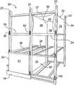
- FIG. 1shows a modular crypt structure with schematically represented walls, roof, and base;
- FIG. 2shows a modular crypt structure frame with a module insert therein and attached closure panel
- FIG. 3shows a perspective view of a frame assembly
- FIG. 4shows a bottom view of a platform formed by a frame assembly
- FIG. 5shows a module insert construction
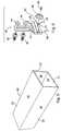
- FIG. 6shows an anchor assembly
- FIG. 7shows a perspective view of a closure panel which is attached to a frame
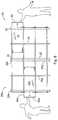
- FIG. 8shows two frame assemblies in a back-to-back orientation
- FIG. 9shows a module insert in conjunction with a crypt sealing cap
- FIG. 10shows an elongated frame assembly
- FIG. 11shows a frame assembly with a roof connected directly to the frame.
- crypt moduleis a chamber, vault, or another space defined within a crypt structure or mausoleum for encapsulating and/or entombing bodily remains.
- Module insertis a piece of material which defines a crypt module within a frame according to the present invention.
- the module insertmay be a flexible or a rigid material. It may comprise plastic, a polymer, fiberglass, or any material sufficient to encapsulate and/or entomb bodily remains.
- “Bodily remains”refers to deceased persons and/or animals, human and/or animal corpse or corpses, portions of corpses and/or deceased persons, cremated remains, or any combination thereof, either enclosed in a casket and/or coffin or not.
- FIG. 1shows an embodiment of the present invention, wherein a modular crypt structure 80 comprises a frame 20 , which defines spaces, or alternatively crypt modules 60 , for insertion of bodily remains.
- Frame 20sits atop a base 76 , and is covered by a roof 74 , which is supported by walls 72 .
- a crypt module 60is formed by placing a module insert 30 within frame 20 , as indicated in FIG. 2 .
- Module insert 30which is shown in FIG. 5 , includes walls 34 with outside surfaces 32 and inside surfaces 36 . Walls 34 define a chamber 35 having a chamber opening 37 at an end of module insert 30 . Generally, an end of module insert 30 opposite chamber opening 37 is sealed, as represented by rear wall surface 38 in FIG. 2 .
- Chamber 35functions as crypt module 60 for insertion of bodily remains or portions of bodily remains when module insert 30 is placed within frame 20 .
- Crypt module 60may also be closed by attaching a closure panel 50 having front face 52 , such as a stone crypt front, to an end of frame 20 adjacent to chamber opening 37 of module insert 30 , thereby encapsulating the bodily remains.
- frame 20comprises a plurality of vertical bars 22 horizontally aligned and a plurality of horizontal cross bars 24 vertically aligned. Additionally, frame 20 may comprise a plurality of support beams 26 which are vertically aligned.
- Cross bars 24are perpendicularly oriented to and intersect vertical bars 22 in a vertical plane. As shown in FIGS. 3-4 , when cross bars 24 and support beams 26 intersect and are perpendicularly oriented in a horizontal plane, cross bars 24 and support beams 26 form a platform 25 for supporting module insert 30 .
- Cross bars 24may be attached to vertical bars 22 via nuts and bolts at joints 21 , and cross bars 24 and support beams 26 may be welded at joints 23 .
- horizontal cross bars 24 , vertical bars 22 and support beams 26may be integrally formed.
- frame 20may comprise any material or combination of materials sufficient to support the weight of bodily remains, and preferably comprises a metal, such as steel or aluminum.
- the vertical bars 22may, for example, comprise 2 inch by 5 inch tube aluminum and horizontal cross bars 24 and support beams 26 comprise 1.5 inch by 2 inch tube aluminum.
- module insert 30comprises walls 34 having outside surfaces 32 and inside surfaces 36 , wherein walls 34 form a chamber 35 having chamber opening 37 .
- Module insert 30is then placed within frame 20 on top of and supported by platform 25 , as shown in FIG. 2 .
- chamber 35 of module insert 30functioning as a crypt module 60 , may receive bodily remains.
- the bodily remainstake the form of a corpse encapsulated within a casket and/or coffin; however, crypt module 60 may receive other forms of bodily remains, such as cremated remains.
- Frame 20may comprise a plurality of platforms 25 , as indicated in the embodiments represented by FIGS. 2-3 . As such, a plurality of module inserts 30 may be placed within frame 20 .
- Module insert 30may comprise any material sufficient to receive and retain bodily remains, such as a plastic material, a polymer material, fiberglass or a metal, for example aluminum.
- crypt module 60 or a plurality of crypt modules 60may be sealed by attaching a closure panel 50 or a plurality thereof to an end of frame 20 adjacent chamber opening 37 , as shown in FIG. 2 .
- front face 52 of closure panel 50may be larger than the chamber opening 37 of module insert 30 , thereby allowing closure panel 50 to completely conceal chamber opening 37 .
- the closure panel 50biases and is attached to a front side of frame 20 .
- a crypt module 60may also comprise a crypt sealing cap 55 , as shown in FIG. 9 .
- a crypt sealing cap 55closes chamber 35 at chamber opening 37 , thereby encapsulating the bodily remains prior to attaching closure panel 50 to frame 20 .
- a crypt sealing cap 55may comprise a fluid-tight material for preventing leakage of fluid into and/or out of crypt module 60 .
- the crypt sealing cap 55comprises a U-shaped cap, having a concave surface 53 , wherein external surfaces of lips 57 of concave surface 53 of sealing cap 55 contact inside surfaces 36 of module insert 30 , thereby fluidly sealing crypt module 60 .
- Line 51indicates the depth of crypt sealing cap 55 within chamber 35 .
- FIGS. 2 and 7show a closure panel 50 attached to both frame 20 and a trim plate 54 , which is attached to frame 20 at a bottom portion thereof.
- Trim plate 54may be biased by a base plate 28 shown in FIG. 7 .
- Base plate 28biases a rear face of trim plate 54 , thereby providing a stable backing for trim plate 54 .
- a plurality of base plates 28may extend around the entire perimeter of frame 20 or a portion thereof for supporting a plurality of trim plates 54 along the sides and front and back ends of frame 20 .
- Closure panel 50 and trim plate 54may comprise a stone material, such as granite or marble to provide an aesthetically pleasing appearance.
- closure panel 50 and trim plate 54are secured to frame 20 by an anchor assembly 40 .
- the anchor assembly 40may include nuts 44 , bolts 42 , spring-loaded flanges 43 , rosette 46 and extension 47 .
- extension 47is alternatively referred to as a slide, which is removably attached to the body of anchor assembly 40 by sliding thereon.
- Extension 47includes top surface 45 and a hole 41 .
- Rosette 46also may include hole 49 .
- Anchor assembly 40is secured to frame 20 near joints 21 , as shown in FIGS. 2 and 7 , by nuts 42 and bolts 44 . Referring to FIG. 7 , anchor assembly 40 may secure closure panel 50 at a periphery of the closure panel 50 near its corners.
- Closure panel 50rests on, and is thereby supported by, top surface 45 of extension 47 .
- Rosette 46biases a front face 52 of closure panel 50 , and is secured by inserting screw 48 through hole 49 of rosette 46 and hole 41 of extension 47 .
- a spring-loaded flange 43biases a rear surface of closure panel 50 pushing closure panel 50 forward against rosette 46 , thereby biasing front face 52 against rosette 46 and securing closure panel 50 in the fore and aft directions.
- a single anchor assemble 40may secure up to four closure panels 50 , two supported on top surface 45 of extension 47 and two below extension 47 , the spring-loaded flanges 43 and rosette 46 biasing corners of a rear surface and the front face 52 , respectively, of each closure panel 50 .
- the anchor assembly 40may comprise an aesthetically pleasing material, such as bronze and/or stainless steel, for example.
- an alternative embodiment of the described inventioncomprises a second frame 20 a .
- frames 20 and 20 aare provided in tandem with back ends 27 and 27 a oriented adjacent to one another.
- a modular crypt structure 80is provided having two opposite ends, wherein module inserts 30 and 30 a may be placed within frame 20 and second frame 20 a , respectively, thereby forming two crypt modules 60 and 60 a , back to back.
- Closure panelsmay then be attached to frames 20 and 20 a to seal respective crypt modules 60 and 60 a .
- two crypt modules 60 and 60 amay be provided back to back in a single integrally formed elongated frame 20 , such as that shown in FIG. 10 .
- module insert 30 or 30 amay be formed such that it comprises two opened ends and extends through both frames 20 and 20 a , supported by platforms 25 and 25 a , respectively, as shown in FIG. 8 , or through elongated frame 20 , as shown in FIG. 10 , thereby providing a crypt module 60 for the insertion of bodily remains of at least two persons.
- a finished modular crypt structure 80may comprise walls 72 , a base 76 and a roof, 74 as shown in FIG. 1 , respectively.
- the walls 72 , base 76 , and roof 74may comprise aesthetically pleasing materials, such as granite, marble, brick, or stucco; however, any other materials sufficient for the user's needs are contemplated.
- crypt modules 60will include a closure panel 50 .
- frame 20will not be visible, as it is shown in FIG. 1 .
- the walls 72may run parallel to the sides of frame 20 and in some instances will run behind the rear of frame 20 , thereby surrounding frame 20 . Roof 74 may then be positioned above frame 20 .
- frame 20may include a wall support bar 29 or a plurality of wall support bars 29 , as shown in FIG. 3 .
- Wall support bar 29which is attached to frame 20 , provides additional stability to wall 72 by biasing an inside face of wall 72 .
- the wallsmay take the form of multiple plates or a continuous slab of material.
- Wall support bar 29as shown, is in a vertical position; however wall support bar 29 may be positioned in other manners, for example, horizontally.
- wall support bar 29may be attached to frame 20 via flanges 19 . When support bar 29 is positioned in a horizontal manner it may be directly connected to vertical bars 22 .
- Both wall support bar 29 and flanges 19may comprise 1.5 inch by 2 inch aluminum tube.
- a finished modular crypt structure 80may be constructed and housed within an existing or concurrently constructed structure.
- a frame 20with accompanying module insert 30 and closure panel 50 , may be directly inserted into a block wall structure comprising for example, concrete.
- a modular crypt structure 80may be also attached as an extension to a preexisting structure. Referring to FIG. 11 , the roof 74 may be secured directed to the frame 20 , wherein roof 74 rests directly upon and is supported by vertical bars 22 .
- frame 20may comprise a plurality of frames 20 in tandem, as discussed above and shown in FIG. 8 , side-by-side, as shown in FIG. 1 , or in any combination of arrangements. These arrangements may also comprise a single integrally formed frame 20 , for example, in FIG. 1 , frame 20 may be a single, elongated frame, rather than a plurality of frames, side-by-side.
- the frame 20may arrive on-site as a set of separate components, for example, as pluralities of vertical bars 22 , horizontal cross bars 24 , and support beams 26 , to be assembled at the place of installation.
- the frame 20may arrive on-site pre-constructed, ready for installation into a pre-existing structure or for erection of new walls around the frame 20 .
- a frame 20may be grouped in any desirable arrangement and secured to pre-existing frames. For example, in FIG. 8 , frame 20 may arrive on-site, subsequently to frame 20 a , which would have been previously constructed. Frame 20 may then be arranged and secured in tandem with frame 20 a.
- time and man-powerare significantly reduced in comparison to that required to build a typical crypt structure.
- the time to construct a modular crypt structure 80 on-siteis estimated to be approximately one-third of the time required to construct and cure a typical concrete crypt structure.
- frame 20comprising a lightweight material, such as aluminum for example, manufacturing and transportation expenses are reduced.
Landscapes
- Engineering & Computer Science (AREA)
- Architecture (AREA)
- Civil Engineering (AREA)
- Structural Engineering (AREA)
- Roof Covering Using Slabs Or Stiff Sheets (AREA)
- Agricultural Chemicals And Associated Chemicals (AREA)
- Surgical Instruments (AREA)
Abstract
Description
Claims (28)
Priority Applications (1)
| Application Number | Priority Date | Filing Date | Title |
|---|---|---|---|
| US15/921,449US10927560B2 (en) | 2009-04-30 | 2018-03-14 | Modular crypt |
Applications Claiming Priority (4)
| Application Number | Priority Date | Filing Date | Title |
|---|---|---|---|
| US17405809P | 2009-04-30 | 2009-04-30 | |
| US12/762,645US9249598B2 (en) | 2009-04-30 | 2010-04-19 | Modular crypt |
| US15/010,059US9945147B2 (en) | 2009-04-30 | 2016-01-29 | Modular crypt |
| US15/921,449US10927560B2 (en) | 2009-04-30 | 2018-03-14 | Modular crypt |
Related Parent Applications (1)
| Application Number | Title | Priority Date | Filing Date |
|---|---|---|---|
| US15/010,059ContinuationUS9945147B2 (en) | 2009-04-30 | 2016-01-29 | Modular crypt |
Publications (2)
| Publication Number | Publication Date |
|---|---|
| US20180305949A1 US20180305949A1 (en) | 2018-10-25 |
| US10927560B2true US10927560B2 (en) | 2021-02-23 |
Family
ID=43029335
Family Applications (3)
| Application Number | Title | Priority Date | Filing Date |
|---|---|---|---|
| US12/762,645Active2031-08-05US9249598B2 (en) | 2009-04-30 | 2010-04-19 | Modular crypt |
| US15/010,059ActiveUS9945147B2 (en) | 2009-04-30 | 2016-01-29 | Modular crypt |
| US15/921,449ActiveUS10927560B2 (en) | 2009-04-30 | 2018-03-14 | Modular crypt |
Family Applications Before (2)
| Application Number | Title | Priority Date | Filing Date |
|---|---|---|---|
| US12/762,645Active2031-08-05US9249598B2 (en) | 2009-04-30 | 2010-04-19 | Modular crypt |
| US15/010,059ActiveUS9945147B2 (en) | 2009-04-30 | 2016-01-29 | Modular crypt |
Country Status (2)
| Country | Link |
|---|---|
| US (3) | US9249598B2 (en) |
| MX (1) | MX339719B (en) |
Families Citing this family (16)
| Publication number | Priority date | Publication date | Assignee | Title |
|---|---|---|---|---|
| US9249598B2 (en) | 2009-04-30 | 2016-02-02 | Matthews Resources, Inc. | Modular crypt |
| US9080344B2 (en) | 2009-04-30 | 2015-07-14 | Matthews Resources, Inc. | Modular crypt and modular crypt system with niche side wall |
| ES1075910Y (en)* | 2011-11-15 | 2012-03-23 | Vico Manuel Juan | PREFABRICATED CONSTRUCTIONS OF NICHE FUNERARIES |
| ES1077590Y (en)* | 2012-07-30 | 2013-04-25 | Composgrave S L | COLUMBARY |
| MX348913B (en)* | 2014-04-23 | 2017-07-04 | Mausoleum S A De C V | Modular system for niches or crypts for depositing ashes and/or dry remains á. |
| BR202015025162Y1 (en)* | 2015-09-30 | 2021-03-30 | Wagner Fortin De Oliveira | CONSTRUCTIVE ARRANGEMENT APPLIED IN LOPULY TYPE STACKABLE SELF-ADJUSTABLE |
| US9777501B2 (en)* | 2015-12-29 | 2017-10-03 | Biondan North America Inc. | Structure for containing cinerary urns and furnerary items in general |
| US10563421B2 (en)* | 2017-03-03 | 2020-02-18 | Bruce Lockhart | Columbarium |
| US10443261B2 (en) | 2017-07-06 | 2019-10-15 | David A. Jaeger | Mausoleum with sealed cylinder assemblies |
| IT201800004240A1 (en)* | 2018-04-05 | 2019-10-05 | CELL FUNERAL STRUCTURE, IN PARTICULAR TO HOUSE OSSARY BOXES AND CINERARY URNS | |
| US11136782B2 (en) | 2018-05-31 | 2021-10-05 | Biondan North America Inc. | Funerary structure for containing funerary objects |
| IT201800005885A1 (en)* | 2018-05-31 | 2019-12-01 | FUNERAL STRUCTURE FOR THE CONTAINMENT OF FUNERAL OBJECTS. | |
| IT201800007681A1 (en)* | 2018-07-31 | 2020-01-31 | Asco Plast Di Zinoni Alessandro | LOCULUS GROUP |
| ES1218996Y (en)* | 2018-08-29 | 2019-01-25 | Coral Smart Invex S L | Modular columbarium for the storage of funeral urns and individual container |
| US11473331B2 (en)* | 2020-04-01 | 2022-10-18 | Merendino Contracting, Inc. | Hybrid mausolino |
| US11988005B2 (en)* | 2020-07-14 | 2024-05-21 | Raymond Conrad, JR. | Crypt system |
Citations (36)
| Publication number | Priority date | Publication date | Assignee | Title |
|---|---|---|---|---|
| US1406192A (en)* | 1919-08-22 | 1922-02-14 | Kennedy George Colvin | Sectional incolsure |
| US1453375A (en)* | 1922-02-13 | 1923-05-01 | William H Allen | Mausoleum |
| US2513951A (en)* | 1947-11-08 | 1950-07-04 | Harold E Mcclellen | Inurnment urn |
| US3183574A (en)* | 1961-06-05 | 1965-05-18 | Greenberg S Sons Inc M | Urn and frame construction |
| US3254773A (en)* | 1961-06-05 | 1966-06-07 | Greenberg S Sons Inc M | Frame construction |
| US3529730A (en)* | 1968-08-05 | 1970-09-22 | Jence F Thompson | Repository for cremated remains |
| US3754805A (en)* | 1971-11-15 | 1973-08-28 | Matthews J & Co | Urn storage assembly |
| US3897663A (en)* | 1973-02-14 | 1975-08-05 | Crypt Systems Inc | Crypt structure |
| US4048772A (en) | 1976-04-05 | 1977-09-20 | Gaul Michael F | Modular crypt system |
| US4073100A (en)* | 1976-07-21 | 1978-02-14 | Digiovanni Jr Francis J | Mausoleum and method of construction |
| US4433883A (en)* | 1981-10-22 | 1984-02-28 | Wallpapers Galore, Inc. | Storage and display system for rolls of decorative wall covering |
| US4523413A (en) | 1983-03-18 | 1985-06-18 | Koppenberg Bruce G | Hanger fastener |
| US4648219A (en)* | 1984-05-16 | 1987-03-10 | Memorial Management And Marketing Concepts, Inc. | Lawn crypt |
| US4669157A (en)* | 1985-02-11 | 1987-06-02 | Schwarten Jerry C | Mausoleum construction |
| US4862655A (en) | 1987-09-14 | 1989-09-05 | Lepage Bernard E | Mass interment system |
| US4928447A (en)* | 1988-11-28 | 1990-05-29 | Walter Stoecklein | Crypt insulation panel and method of installation |
| US5115607A (en)* | 1991-05-06 | 1992-05-26 | Norwalk Vault Company Of Bridgeport, Inc. | Casket enclosure and method of storing same in a burial crypt |
| US5243794A (en) | 1991-08-06 | 1993-09-14 | Christian Memorial Cultural Center | Modular crypt assembly |
| US5408787A (en)* | 1993-11-03 | 1995-04-25 | Barnett; Jerome J. | Mausoleum construction |
| US5419091A (en)* | 1993-11-01 | 1995-05-30 | Mercury Development Corporation | Positive-lock slab support |
| US5894699A (en)* | 1997-08-18 | 1999-04-20 | Fulton; Robert H. | Crypt construction |
| US5899045A (en)* | 1996-06-24 | 1999-05-04 | Giannarelli; Emilio Teodoro | Mausoleum |
| US6105315A (en)* | 1998-07-24 | 2000-08-22 | Stoecklein; Walter J. | Modular mausoleum and crypt structure and methods of constructing same |
| US6250025B1 (en)* | 2000-05-04 | 2001-06-26 | Greenwood, Inc. | Assembleable columbarium tower |
| US6578323B1 (en)* | 2000-09-19 | 2003-06-17 | Ronald Richard Zartman | Columbarium and niche unit therefor |
| US6681534B2 (en)* | 2001-04-06 | 2004-01-27 | Pyramid Development Group Llc | Pyramid mausoleum and columbarium system and method |
| US6799399B2 (en)* | 2001-02-12 | 2004-10-05 | Daniel Thomas Dudek | Burial structure for the interment of human remains and significant memorabilia |
| US7415800B2 (en) | 2003-03-11 | 2008-08-26 | Harry Stienwand | Columbarium with improved security |
| US20090229197A1 (en)* | 2008-03-11 | 2009-09-17 | Santiago Bach Lahor | Modular columbarium |
| US7591053B2 (en) | 2006-01-27 | 2009-09-22 | Giuseppe Bosisio S.R.L. | Modular structure for cemetery constructions |
| US20100162639A1 (en)* | 2008-12-29 | 2010-07-01 | Legend Memorial Cenotaphs, Inc. | System and method for archival display in a cenotaph memorial facility |
| CA2702682A1 (en) | 2009-04-30 | 2010-10-30 | Matthews Resources, Inc. | Modular crypt |
| MX2010004649A (en) | 2009-04-30 | 2010-11-01 | Matthews Resources Inc | Modular crypt. |
| US7926228B1 (en)* | 2010-10-08 | 2011-04-19 | Snow William L | Cremation niche |
| US20110154748A1 (en) | 2009-04-30 | 2011-06-30 | Matthews Resources, Inc. | Modular Crypt and Modular Crypt System with Niche Side Wall |
| CA2762740A1 (en) | 2011-01-10 | 2012-07-10 | Matthews Resources, Inc. | Modular crypt and modular crypt system with niche side wall |
- 2010
- 2010-04-19USUS12/762,645patent/US9249598B2/enactiveActive
- 2010-04-28MXMX2010004649Apatent/MX339719B/enactiveIP Right Grant
- 2016
- 2016-01-29USUS15/010,059patent/US9945147B2/enactiveActive
- 2018
- 2018-03-14USUS15/921,449patent/US10927560B2/enactiveActive
Patent Citations (43)
| Publication number | Priority date | Publication date | Assignee | Title |
|---|---|---|---|---|
| US1406192A (en)* | 1919-08-22 | 1922-02-14 | Kennedy George Colvin | Sectional incolsure |
| US1453375A (en)* | 1922-02-13 | 1923-05-01 | William H Allen | Mausoleum |
| US2513951A (en)* | 1947-11-08 | 1950-07-04 | Harold E Mcclellen | Inurnment urn |
| US3183574A (en)* | 1961-06-05 | 1965-05-18 | Greenberg S Sons Inc M | Urn and frame construction |
| US3254773A (en)* | 1961-06-05 | 1966-06-07 | Greenberg S Sons Inc M | Frame construction |
| US3529730A (en)* | 1968-08-05 | 1970-09-22 | Jence F Thompson | Repository for cremated remains |
| US3754805A (en)* | 1971-11-15 | 1973-08-28 | Matthews J & Co | Urn storage assembly |
| US3897663A (en)* | 1973-02-14 | 1975-08-05 | Crypt Systems Inc | Crypt structure |
| US4048772A (en) | 1976-04-05 | 1977-09-20 | Gaul Michael F | Modular crypt system |
| US4073100A (en)* | 1976-07-21 | 1978-02-14 | Digiovanni Jr Francis J | Mausoleum and method of construction |
| US4433883A (en)* | 1981-10-22 | 1984-02-28 | Wallpapers Galore, Inc. | Storage and display system for rolls of decorative wall covering |
| US4523413A (en) | 1983-03-18 | 1985-06-18 | Koppenberg Bruce G | Hanger fastener |
| US4648219A (en)* | 1984-05-16 | 1987-03-10 | Memorial Management And Marketing Concepts, Inc. | Lawn crypt |
| US4669157A (en)* | 1985-02-11 | 1987-06-02 | Schwarten Jerry C | Mausoleum construction |
| US4862655A (en) | 1987-09-14 | 1989-09-05 | Lepage Bernard E | Mass interment system |
| US4928447A (en)* | 1988-11-28 | 1990-05-29 | Walter Stoecklein | Crypt insulation panel and method of installation |
| US5115607A (en)* | 1991-05-06 | 1992-05-26 | Norwalk Vault Company Of Bridgeport, Inc. | Casket enclosure and method of storing same in a burial crypt |
| US5243794A (en) | 1991-08-06 | 1993-09-14 | Christian Memorial Cultural Center | Modular crypt assembly |
| US5419091A (en)* | 1993-11-01 | 1995-05-30 | Mercury Development Corporation | Positive-lock slab support |
| US5408787A (en)* | 1993-11-03 | 1995-04-25 | Barnett; Jerome J. | Mausoleum construction |
| US5899045A (en)* | 1996-06-24 | 1999-05-04 | Giannarelli; Emilio Teodoro | Mausoleum |
| US5894699A (en)* | 1997-08-18 | 1999-04-20 | Fulton; Robert H. | Crypt construction |
| US6105315A (en)* | 1998-07-24 | 2000-08-22 | Stoecklein; Walter J. | Modular mausoleum and crypt structure and methods of constructing same |
| US6250025B1 (en)* | 2000-05-04 | 2001-06-26 | Greenwood, Inc. | Assembleable columbarium tower |
| US6578323B1 (en)* | 2000-09-19 | 2003-06-17 | Ronald Richard Zartman | Columbarium and niche unit therefor |
| US6799399B2 (en)* | 2001-02-12 | 2004-10-05 | Daniel Thomas Dudek | Burial structure for the interment of human remains and significant memorabilia |
| US6681534B2 (en)* | 2001-04-06 | 2004-01-27 | Pyramid Development Group Llc | Pyramid mausoleum and columbarium system and method |
| US7415800B2 (en) | 2003-03-11 | 2008-08-26 | Harry Stienwand | Columbarium with improved security |
| US7591053B2 (en) | 2006-01-27 | 2009-09-22 | Giuseppe Bosisio S.R.L. | Modular structure for cemetery constructions |
| US20090229197A1 (en)* | 2008-03-11 | 2009-09-17 | Santiago Bach Lahor | Modular columbarium |
| US20100162639A1 (en)* | 2008-12-29 | 2010-07-01 | Legend Memorial Cenotaphs, Inc. | System and method for archival display in a cenotaph memorial facility |
| MX2010004649A (en) | 2009-04-30 | 2010-11-01 | Matthews Resources Inc | Modular crypt. |
| CA2702682A1 (en) | 2009-04-30 | 2010-10-30 | Matthews Resources, Inc. | Modular crypt |
| US20100275529A1 (en) | 2009-04-30 | 2010-11-04 | Matthews Resources, Inc. | Modular Crypt |
| US20110154748A1 (en) | 2009-04-30 | 2011-06-30 | Matthews Resources, Inc. | Modular Crypt and Modular Crypt System with Niche Side Wall |
| US9080344B2 (en)* | 2009-04-30 | 2015-07-14 | Matthews Resources, Inc. | Modular crypt and modular crypt system with niche side wall |
| US9249598B2 (en) | 2009-04-30 | 2016-02-02 | Matthews Resources, Inc. | Modular crypt |
| US20160138292A1 (en)* | 2009-04-30 | 2016-05-19 | Matthews Resources, Inc. | Modular crypt and modular crypt system with niche side wall |
| US20160251871A1 (en) | 2009-04-30 | 2016-09-01 | Matthews Resources, Inc. | Modular crypt |
| US9458643B2 (en)* | 2009-04-30 | 2016-10-04 | Matthews Resources, Inc. | Modular crypt and modular crypt system with niche side wall |
| US20170089091A1 (en) | 2009-04-30 | 2017-03-30 | Matthews Resources, Inc. | Modular crypt and modular crypt system with niche side wall |
| US7926228B1 (en)* | 2010-10-08 | 2011-04-19 | Snow William L | Cremation niche |
| CA2762740A1 (en) | 2011-01-10 | 2012-07-10 | Matthews Resources, Inc. | Modular crypt and modular crypt system with niche side wall |
Non-Patent Citations (3)
| Title |
|---|
| Agganciare/Ripiani Ai 4 Pilastri Gia Posizionait, Partendo Dal Basso, Ferrarini System, at least as early as 2009. |
| Osisio Antica Fonderia D'Arte Catalogo Cimiteri 2008, Catalog. |
| Strutture Prefabbricate: Schedario Dei Collegamenti, May 2007. |
Also Published As
| Publication number | Publication date |
|---|---|
| US20100275529A1 (en) | 2010-11-04 |
| US20160251871A1 (en) | 2016-09-01 |
| US9249598B2 (en) | 2016-02-02 |
| MX339719B (en) | 2016-06-07 |
| US9945147B2 (en) | 2018-04-17 |
| MX2010004649A (en) | 2010-11-01 |
| US20180305949A1 (en) | 2018-10-25 |
Similar Documents
| Publication | Publication Date | Title |
|---|---|---|
| US12129677B2 (en) | Modular crypt and modular crypt system with niche side wall | |
| US10927560B2 (en) | Modular crypt | |
| US5881505A (en) | Free-standing, prefabricated cremation memorial for cremation remains | |
| US7739776B2 (en) | Modular columbarium system | |
| US7926228B1 (en) | Cremation niche | |
| US11505958B2 (en) | Modular pool | |
| US4669157A (en) | Mausoleum construction | |
| CA2762740C (en) | Modular crypt and modular crypt system with niche side wall | |
| US5010697A (en) | Mausoleum construction | |
| CA2702682C (en) | Modular crypt | |
| WO2013182997A1 (en) | Building unit and modular unit construction system comprising one or more such building units | |
| US20190010724A1 (en) | Mausoleum With Sealed Cylinder Assemblies | |
| KR200172570Y1 (en) | A family burial ground | |
| JPH116332A (en) | Assembled exterior wall construction | |
| JP6290113B2 (en) | Compartmental cemetery using firewood | |
| JP3157099U (en) | Ossuary | |
| KR100549849B1 (en) | Ossuary | |
| WO2025191620A1 (en) | Method for assembling a prefabricated modular swimming pool | |
| JP3720556B2 (en) | Small stone tomb and stone morgue | |
| KR20010088891A (en) | structure for charnel box | |
| JP2010261290A (en) | Masonry charnel house structure by assembling method | |
| JP2009013624A (en) | Support frame structure | |
| JPH0734468A (en) | Foundation forming member and foundation forming method | |
| JPH05195652A (en) | Tomb | |
| ES2534255A1 (en) | Formwork for funerary structures and system for constructing said structures |
Legal Events
| Date | Code | Title | Description |
|---|---|---|---|
| FEPP | Fee payment procedure | Free format text:ENTITY STATUS SET TO UNDISCOUNTED (ORIGINAL EVENT CODE: BIG.); ENTITY STATUS OF PATENT OWNER: LARGE ENTITY | |
| AS | Assignment | Owner name:MATTHEWS RESOURCES, INC., DELAWARE Free format text:ASSIGNMENT OF ASSIGNORS INTEREST;ASSIGNORS:BRIDGEMAN, KENNETH B.;YOUNG, CHARLES T.;REEL/FRAME:045648/0956 Effective date:20110228 | |
| AS | Assignment | Owner name:MATTHEWS INTERNATIONAL CORPORATION, PENNSYLVANIA Free format text:ASSIGNMENT OF ASSIGNORS INTEREST;ASSIGNOR:MATTHEWS RESOURCES, INC.;REEL/FRAME:047211/0521 Effective date:20170929 | |
| STPP | Information on status: patent application and granting procedure in general | Free format text:NON FINAL ACTION MAILED | |
| STPP | Information on status: patent application and granting procedure in general | Free format text:RESPONSE TO NON-FINAL OFFICE ACTION ENTERED AND FORWARDED TO EXAMINER | |
| STPP | Information on status: patent application and granting procedure in general | Free format text:FINAL REJECTION MAILED | |
| STPP | Information on status: patent application and granting procedure in general | Free format text:RESPONSE AFTER FINAL ACTION FORWARDED TO EXAMINER | |
| STPP | Information on status: patent application and granting procedure in general | Free format text:ADVISORY ACTION MAILED | |
| STPP | Information on status: patent application and granting procedure in general | Free format text:DOCKETED NEW CASE - READY FOR EXAMINATION | |
| STPP | Information on status: patent application and granting procedure in general | Free format text:NON FINAL ACTION MAILED | |
| STCF | Information on status: patent grant | Free format text:PATENTED CASE | |
| MAFP | Maintenance fee payment | Free format text:PAYMENT OF MAINTENANCE FEE, 4TH YEAR, LARGE ENTITY (ORIGINAL EVENT CODE: M1551); ENTITY STATUS OF PATENT OWNER: LARGE ENTITY Year of fee payment:4 | |
| AS | Assignment | Owner name:TRUIST BANK, NORTH CAROLINA Free format text:SECURITY INTEREST;ASSIGNOR:MATTHEWS INTERNATIONAL CORPORATION;REEL/FRAME:069379/0573 Effective date:20241112 Owner name:CITIZENS BANK, N.A., PENNSYLVANIA Free format text:SECURITY INTEREST;ASSIGNOR:MATTHEWS INTERNATIONAL CORPORATION;REEL/FRAME:069379/0528 Effective date:20241112 |