US10926280B2 - Dispenser pump using electrically activated material - Google Patents
Dispenser pump using electrically activated materialDownload PDFInfo
- Publication number
- US10926280B2 US10926280B2US15/477,529US201715477529AUS10926280B2US 10926280 B2US10926280 B2US 10926280B2US 201715477529 AUS201715477529 AUS 201715477529AUS 10926280 B2US10926280 B2US 10926280B2
- Authority
- US
- United States
- Prior art keywords
- flexible membrane
- pump
- pumping chamber
- voltage
- fluid
- Prior art date
- Legal status (The legal status is an assumption and is not a legal conclusion. Google has not performed a legal analysis and makes no representation as to the accuracy of the status listed.)
- Expired - Fee Related, expires
Links
Images


Classifications
- F—MECHANICAL ENGINEERING; LIGHTING; HEATING; WEAPONS; BLASTING
- F04—POSITIVE - DISPLACEMENT MACHINES FOR LIQUIDS; PUMPS FOR LIQUIDS OR ELASTIC FLUIDS
- F04B—POSITIVE-DISPLACEMENT MACHINES FOR LIQUIDS; PUMPS
- F04B43/00—Machines, pumps, or pumping installations having flexible working members
- F04B43/02—Machines, pumps, or pumping installations having flexible working members having plate-like flexible members, e.g. diaphragms
- F04B43/04—Pumps having electric drive
- B05B11/3028—
- A—HUMAN NECESSITIES
- A47—FURNITURE; DOMESTIC ARTICLES OR APPLIANCES; COFFEE MILLS; SPICE MILLS; SUCTION CLEANERS IN GENERAL
- A47K—SANITARY EQUIPMENT NOT OTHERWISE PROVIDED FOR; TOILET ACCESSORIES
- A47K5/00—Holders or dispensers for soap, toothpaste, or the like
- A47K5/06—Dispensers for soap
- A47K5/12—Dispensers for soap for liquid or pasty soap
- A47K5/1202—Dispensers for soap for liquid or pasty soap dispensing dosed volume
- A47K5/1208—Dispensers for soap for liquid or pasty soap dispensing dosed volume by means of a flexible dispensing chamber
- A—HUMAN NECESSITIES
- A47—FURNITURE; DOMESTIC ARTICLES OR APPLIANCES; COFFEE MILLS; SPICE MILLS; SUCTION CLEANERS IN GENERAL
- A47K—SANITARY EQUIPMENT NOT OTHERWISE PROVIDED FOR; TOILET ACCESSORIES
- A47K5/00—Holders or dispensers for soap, toothpaste, or the like
- A47K5/06—Dispensers for soap
- A47K5/12—Dispensers for soap for liquid or pasty soap
- A47K5/1211—Dispensers for soap for liquid or pasty soap using pressure on soap, e.g. with piston
- A—HUMAN NECESSITIES
- A47—FURNITURE; DOMESTIC ARTICLES OR APPLIANCES; COFFEE MILLS; SPICE MILLS; SUCTION CLEANERS IN GENERAL
- A47K—SANITARY EQUIPMENT NOT OTHERWISE PROVIDED FOR; TOILET ACCESSORIES
- A47K5/00—Holders or dispensers for soap, toothpaste, or the like
- A47K5/06—Dispensers for soap
- A47K5/12—Dispensers for soap for liquid or pasty soap
- A47K5/1217—Electrical control means for the dispensing mechanism
- B—PERFORMING OPERATIONS; TRANSPORTING
- B05—SPRAYING OR ATOMISING IN GENERAL; APPLYING FLUENT MATERIALS TO SURFACES, IN GENERAL
- B05B—SPRAYING APPARATUS; ATOMISING APPARATUS; NOZZLES
- B05B11/00—Single-unit hand-held apparatus in which flow of contents is produced by the muscular force of the operator at the moment of use
- B05B11/01—Single-unit hand-held apparatus in which flow of contents is produced by the muscular force of the operator at the moment of use characterised by the means producing the flow
- B05B11/10—Pump arrangements for transferring the contents from the container to a pump chamber by a sucking effect and forcing the contents out through the dispensing nozzle
- B05B11/1028—Pumps having a pumping chamber with a deformable wall
- B—PERFORMING OPERATIONS; TRANSPORTING
- B05—SPRAYING OR ATOMISING IN GENERAL; APPLYING FLUENT MATERIALS TO SURFACES, IN GENERAL
- B05B—SPRAYING APPARATUS; ATOMISING APPARATUS; NOZZLES
- B05B11/00—Single-unit hand-held apparatus in which flow of contents is produced by the muscular force of the operator at the moment of use
- B05B11/01—Single-unit hand-held apparatus in which flow of contents is produced by the muscular force of the operator at the moment of use characterised by the means producing the flow
- B05B11/10—Pump arrangements for transferring the contents from the container to a pump chamber by a sucking effect and forcing the contents out through the dispensing nozzle
- B05B11/1042—Components or details
- B05B11/1052—Actuation means
- B05B11/3032—
- B05B11/3052—
- B65D83/0055—
- B—PERFORMING OPERATIONS; TRANSPORTING
- B65—CONVEYING; PACKING; STORING; HANDLING THIN OR FILAMENTARY MATERIAL
- B65D—CONTAINERS FOR STORAGE OR TRANSPORT OF ARTICLES OR MATERIALS, e.g. BAGS, BARRELS, BOTTLES, BOXES, CANS, CARTONS, CRATES, DRUMS, JARS, TANKS, HOPPERS, FORWARDING CONTAINERS; ACCESSORIES, CLOSURES, OR FITTINGS THEREFOR; PACKAGING ELEMENTS; PACKAGES
- B65D83/00—Containers or packages with special means for dispensing contents
- B65D83/771—Containers or packages with special means for dispensing contents for dispensing fluent contents by means of a flexible bag or a deformable membrane or diaphragm
- F—MECHANICAL ENGINEERING; LIGHTING; HEATING; WEAPONS; BLASTING
- F04—POSITIVE - DISPLACEMENT MACHINES FOR LIQUIDS; PUMPS FOR LIQUIDS OR ELASTIC FLUIDS
- F04B—POSITIVE-DISPLACEMENT MACHINES FOR LIQUIDS; PUMPS
- F04B43/00—Machines, pumps, or pumping installations having flexible working members
- F04B43/02—Machines, pumps, or pumping installations having flexible working members having plate-like flexible members, e.g. diaphragms
- B—PERFORMING OPERATIONS; TRANSPORTING
- B05—SPRAYING OR ATOMISING IN GENERAL; APPLYING FLUENT MATERIALS TO SURFACES, IN GENERAL
- B05B—SPRAYING APPARATUS; ATOMISING APPARATUS; NOZZLES
- B05B11/00—Single-unit hand-held apparatus in which flow of contents is produced by the muscular force of the operator at the moment of use
- B05B11/01—Single-unit hand-held apparatus in which flow of contents is produced by the muscular force of the operator at the moment of use characterised by the means producing the flow
- B05B11/10—Pump arrangements for transferring the contents from the container to a pump chamber by a sucking effect and forcing the contents out through the dispensing nozzle
- B05B11/1028—Pumps having a pumping chamber with a deformable wall
- B05B11/1032—Pumps having a pumping chamber with a deformable wall actuated without substantial movement of the nozzle in the direction of the pressure stroke
- B—PERFORMING OPERATIONS; TRANSPORTING
- B05—SPRAYING OR ATOMISING IN GENERAL; APPLYING FLUENT MATERIALS TO SURFACES, IN GENERAL
- B05B—SPRAYING APPARATUS; ATOMISING APPARATUS; NOZZLES
- B05B11/00—Single-unit hand-held apparatus in which flow of contents is produced by the muscular force of the operator at the moment of use
- B05B11/01—Single-unit hand-held apparatus in which flow of contents is produced by the muscular force of the operator at the moment of use characterised by the means producing the flow
- B05B11/10—Pump arrangements for transferring the contents from the container to a pump chamber by a sucking effect and forcing the contents out through the dispensing nozzle
- B05B11/1028—Pumps having a pumping chamber with a deformable wall
- B05B11/1033—Pumps having a pumping chamber with a deformable wall the deformable wall, the inlet and outlet valve elements being integrally formed, e.g. moulded
Definitions
- the current inventionpertains to pumping mechanisms used in fluid product dispensers, and more specifically to pumping mechanisms that use electrically activating polymers to pressurize a fluid chamber for dispensing fluid product through a nozzle.
- dispense hand care productsfrom a dispenser mounted to a wall or stand.
- Such dispenserstypically have a replaceable reservoir containing hand soap, lotion or sanitizer.
- Some modelsdispense product automatically by sensing when a person's hand has been placed under the dispenser. The sensor sends signals to a controller, which in turn operates a pump that forces fluid through a nozzle and onto the person's hand.
- Dispensersmay be conveniently located in building entrances, bathrooms, or lunchrooms providing convenient accessibility to passersby. However, not all areas are appropriately suited for supplying power to dispensers. As such, dispensers are typically equipped with an onboard power source, typically batteries.
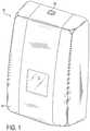
- FIG. 1is a perspective view of a fluid product dispenser according to the embodiments of the present invention.
- FIG. 2is a cross-sectional view of the fluid product dispenser showing the internal components of the dispenser.
- FIG. 3is a cross-sectional view showing a schematic representation of a fluid product pump in the electrically de-energized state according to the embodiments of the present invention.
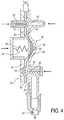
- FIG. 4is a cross-sectional view showing a schematic representation of a fluid product pump in the electrically energized state according to the embodiments of the present invention.
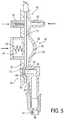
- FIG. 5is a cross-sectional view showing a schematic representation of another embodiment of the fluid product pump according to the embodiments of the present invention.
- Dispenser 10meters out product, which may include hand care products like soap, lotions or sanitizers, although other types of fluid products may be dispensed from the product dispenser.
- dispenser 10includes a base 14 and a cover 18 which when closed define an internal area that holds the components of the dispenser 10 .
- the base 14may be generally rigid having a structural configuration suitable for supporting a pump and a fluid reservoir 30 , as well as other components to be discussed later.
- the dispenser 10can be mounted to a wall, stand or other structure, not shown in the figures, and so the base 14 includes mounting holes or brackets capable of receiving one or more fasteners.
- the base 14may further include a hinge 22 onto which the cover 18 is pivotally attached.
- a latch 26secures the 18 cover in place and manually releases to allow access to the interior region of the dispenser 10 .
- the cover 18may be generally concave and may include a window 11 positioned to allow service personnel visual access to the fluid reservoir 30 .
- fluid reservoir 30is constructed to contain hand care products.
- the reservoir 30may be a reusable container and refilled with product as needed.
- the reservoir 30may be disposable and replaced when empty. Access to the reservoir 30 is gained by unlatching and pivoting the cover 18 away from the base 14 thereby exposing the interior of the dispenser 10 .
- the reservoir 30may held in place by a ledge and/or wall extended from the base 14 .
- the reservoir 30is removed and replaced with another reservoir 30 for sanitary reasons.
- Such replaceable reservoirsare referred to hereafter as refill units 34 .
- the refill unit 34may be constructed from pliable sheet-like material, referred to as a bag, and may include an outlet attached to a side or an end of the bag. Still other refill units 34 may be constructed from generally rigid or semi-rigid plastic for use in an upright or an inverted mounting configuration. In FIG. 2 , the refill unit 34 is stored completely within the dispenser housing. However, other structural and mounting configurations for the refill unit 34 may be selected without departing from the intended scope of coverage of the embodiments of the present invention.
- a dispenser pump 40having a pump inlet 42 and a pump outlet 46 .
- the pump outlet 46is connected to a nozzle 47 for dispensing fluid product from the dispenser 10 .
- the pump inlet 42is fluidly connected to the refill unit 34 . More specifically, the pump inlet 42 is connected to an end of the refill unit 34 to minimize waste.
- the pump 40is disposable and is provided attached to the refill unit 34 as an assembly. In this manner, every wetted component of the dispenser 10 is disposed of when the refill unit 34 is replaced.
- pump 40includes a pumping chamber shown generally at 50 .
- pumping chamber 50has a generally concave region 52 .
- Inlet 42extends from a top side of the concave region 52 and outlet 46 extends from the distal bottom end of the concave region 52 , although other positions of the inlet and outlet relative to the pumping chamber 50 may be chosen with sound judgment. In this way, gravity assists in drawing product from the refill unit 34 into the concave region 52 .
- An actuatordiscussed in detail below, pressurizes chamber 50 thereby expelling product through the outlet 46 and the nozzle 47 . It will be appreciated that other configurations of pumping chambers 50 may be used without departing from the intended scope of coverage of the embodiments of the present invention.
- Fluid in the pumping chamber 50may be pressurized by displacing one or more walls that make up the pumping chamber 50 .
- chamber 50may be constructed from one or more rigid wall sections 53 and by a flexible membrane 70 .
- Pressureis generated in the concave region 52 from a biasing device 54 located adjacent the flexible membrane 70 .
- biasing device 54comprises a leaf spring, or a coil spring 55 .
- other types of springs or biasing devicesmay be used. Force from the biasing device 54 pushes against the membrane 70 constricting the volume of fluid in the chamber 50 thereby pressurizing the product inside.
- membrane 70is constructed from flexible polymeric material.
- the flexible materialpossesses memory and has a predetermined stiffness, i.e. resistance to bending.
- membrane 70is made from Silicone, or alternatively from Polyurethane.
- other types of materialthat have the requisite characteristics of stiffness and memory may be used as needed for operation of the pump 40 . Accordingly, after membrane 70 is displaced, i.e. biased by device 54 , it will tend to retain its original shape and return to its unbiased configuration when the force is removed. It will be appreciated that the spring constants of the biasing device 54 may be matched to the stiffness of the membrane 70 in a manner suitable for operation of the dispenser 10 as described herein.
- the membrane 70further includes electrically conductive material applied to each of its opposing faces 70 ′, 70 ′′.
- the electrically conductive materialcomprises carbon particles adhered to the surface of the membrane in a relatively thin layer.
- Each face 70 ′, 70 ′′ of the membrane, and more specifically each of the electrically conductive layers 72is respectively connected to opposite polarity terminals of a DC voltage power source.
- the polymeric material of the membrane 70functions as a dielectric between the electrically conductive layers 72 .
- the polarizing effect of the applied voltagealters the characteristics of membrane 70 as described above.
- Voltages applied to the membrane 70may be in the range of 2 kV to 4 kV. However, any range of voltage potential may be applied as is appropriate for use in actuating the pump 40 . In that the phenomenon of altering the stiffness of a dielectric polymer by the application of voltage is known in the art, no further explanation will be offered here.
- a first valveshown generally at 80
- a second valveshown generally at 81
- the valves 80 , 81prevent the back flow of product into refill unit 34 and prevent product from leaking through the nozzle before the dispenser is activated.
- membrane 70may be used as valves 80 , 81 to selectively open and close inlet 42 and outlet 46 as mentioned above.
- an additional biasing device 57may be positioned adjacent to membrane 70 and in proximity to inlet 42 .
- membrane 70loses stiffness over the entire area covered by the conductive layers 72 . Accordingly, membrane 70 becomes more pliable allowing biasing device 57 to press membrane 70 into sealing contact with the inlet 42 thereby preventing fluid flow back into the refill unit 34 .
- biasing devices 54 and 57displace membrane 70 at the same time. Accordingly, it is contemplated in an alternate embodiment that one single biasing device, not shown in the figures, may be used to both displace fluid from the pumping chamber 50 and seal the inlet 42 . Thus the biasing device may be specifically configured and the inlet 42 may be positioned proximal to the pumping chamber to facilitate both actions with a single biasing element.
- biasing device 59may be included and positioned to engage membrane 70 at the location of the outlet 46 . It is noted that the inlet 42 and outlet 46 must be fluidly sealed at opposite times during operation of the pump 40 . Hence, biasing device 59 is positioned to move membrane 70 away from the outlet 46 when fluid in the pumping chamber 50 is pressurized. It follows that, in the de-energized state, membrane 70 is configured to cover the outlet 46 thereby preventing fluid flow therethrough.
- a raised rim 49may be positioned around the opening of the outlet 46 .
- protrusionsreferred to herein as ribs 51 , may be fashioned to extend from the one or more rigid wall sections 53 opposite that of the raised rim 49 . In this way, the stiffness and memory of the membrane 70 force it into contact with the outlet 46 in a crimping action (reference FIG. 5 ).
- FIG. 5depicts an embodiment of the present invention that does not include a dedicated biasing device to force the membrane 70 out of engagement with the outlet 46 .
- the stiffness and/or thickness of the membrane 70may be selected so that as pressure in the pumping chamber 50 increases, a threshold is reached that overcomes the rigidity of the membrane 70 thus allowing fluid to flow through the nozzle 47 . While the current embodiment depicts both rim 49 and ribs 51 , variations are contemplated excluding one or the other of these components.
Landscapes
- Engineering & Computer Science (AREA)
- Health & Medical Sciences (AREA)
- Public Health (AREA)
- Mechanical Engineering (AREA)
- General Engineering & Computer Science (AREA)
- Reciprocating Pumps (AREA)
Abstract
Description
Claims (19)
Priority Applications (1)
| Application Number | Priority Date | Filing Date | Title |
|---|---|---|---|
| US15/477,529US10926280B2 (en) | 2013-09-20 | 2017-04-03 | Dispenser pump using electrically activated material |
Applications Claiming Priority (3)
| Application Number | Priority Date | Filing Date | Title |
|---|---|---|---|
| US201361880270P | 2013-09-20 | 2013-09-20 | |
| US14/489,850US9610600B2 (en) | 2013-09-20 | 2014-09-18 | Dispenser pump using electrically activated material |
| US15/477,529US10926280B2 (en) | 2013-09-20 | 2017-04-03 | Dispenser pump using electrically activated material |
Related Parent Applications (1)
| Application Number | Title | Priority Date | Filing Date |
|---|---|---|---|
| US14/489,850ContinuationUS9610600B2 (en) | 2013-09-20 | 2014-09-18 | Dispenser pump using electrically activated material |
Publications (2)
| Publication Number | Publication Date |
|---|---|
| US20170203316A1 US20170203316A1 (en) | 2017-07-20 |
| US10926280B2true US10926280B2 (en) | 2021-02-23 |
Family
ID=51656112
Family Applications (3)
| Application Number | Title | Priority Date | Filing Date |
|---|---|---|---|
| US14/489,850ActiveUS9610600B2 (en) | 2013-09-20 | 2014-09-18 | Dispenser pump using electrically activated material |
| US14/662,539CeasedUS9517484B2 (en) | 2013-09-20 | 2015-03-19 | Dispenser pump using electrically activated material |
| US15/477,529Expired - Fee RelatedUS10926280B2 (en) | 2013-09-20 | 2017-04-03 | Dispenser pump using electrically activated material |
Family Applications Before (2)
| Application Number | Title | Priority Date | Filing Date |
|---|---|---|---|
| US14/489,850ActiveUS9610600B2 (en) | 2013-09-20 | 2014-09-18 | Dispenser pump using electrically activated material |
| US14/662,539CeasedUS9517484B2 (en) | 2013-09-20 | 2015-03-19 | Dispenser pump using electrically activated material |
Country Status (6)
| Country | Link |
|---|---|
| US (3) | US9610600B2 (en) |
| EP (1) | EP3047148A1 (en) |
| JP (1) | JP6599312B2 (en) |
| AU (1) | AU2014323512A1 (en) |
| CA (2) | CA2924662C (en) |
| WO (1) | WO2015042235A1 (en) |
Families Citing this family (8)
| Publication number | Priority date | Publication date | Assignee | Title |
|---|---|---|---|---|
| USRE48010E1 (en)* | 2013-09-20 | 2020-05-26 | Gojo Industries, Inc. | Dispenser using electrically activated material |
| AU2014323512A1 (en) | 2013-09-20 | 2016-03-10 | Gojo Industries, Inc. | Dispenser pump using electrically activated material |
| WO2016043809A1 (en)* | 2014-09-18 | 2016-03-24 | Gojo Industries, Inc. | Dispenser pump using electrically activated material |
| US10743721B2 (en) | 2013-11-27 | 2020-08-18 | Archer Manufacturing, Inc. | Tamper-resistant devices and systems for wall-mounted dispensers |
| US10123661B2 (en)* | 2013-11-27 | 2018-11-13 | Archer Manufacturing, Inc. | Tamper-proof and ligation resistant dispenser for liquids |
| US10743720B2 (en) | 2013-11-27 | 2020-08-18 | Archer Manufacturing, Inc. | Tamper-resistant devices and systems for wall-mounted dispensers |
| DE102015206589A1 (en) | 2015-04-14 | 2016-10-20 | Continental Automotive Gmbh | A method of determining a temperature of a diaphragm of a pump |
| WO2021059697A1 (en)* | 2019-09-25 | 2021-04-01 | 花王株式会社 | Dispenser |
Citations (37)
| Publication number | Priority date | Publication date | Assignee | Title |
|---|---|---|---|---|
| US2412397A (en)* | 1943-12-31 | 1946-12-10 | Lyndus E Harper | Flexible tube pump |
| US2895653A (en)* | 1957-06-27 | 1959-07-21 | American Nat Bank | Measuring and dispensing valve |
| US3672791A (en)* | 1970-07-17 | 1972-06-27 | Ladish Co | Pumping system with controlled liquid addition |
| US4042153A (en)* | 1973-03-14 | 1977-08-16 | Standard Oil Company | Liquid dropping device |
| US4121584A (en) | 1976-10-15 | 1978-10-24 | R. Scott Turner | Method and apparatus for controlling the dispensing of fluid |
| US4231287A (en)* | 1978-05-01 | 1980-11-04 | Physics International Company | Spring diaphragm |
| US4290346A (en)* | 1979-04-30 | 1981-09-22 | Abbott Laboratories | Intravenous pump chamber |
| US4303376A (en)* | 1979-07-09 | 1981-12-01 | Baxter Travenol Laboratories, Inc. | Flow metering cassette and controller |
| US4453931A (en) | 1980-08-01 | 1984-06-12 | Oximetrix, Inc. | Intravenous metering device |
| US4479761A (en) | 1982-12-28 | 1984-10-30 | Baxter Travenol Laboratories, Inc. | Actuator apparatus for a prepackaged fluid processing module having pump and valve elements operable in response to externally applied pressures |
| US5016779A (en)* | 1990-02-09 | 1991-05-21 | Nic Williamson | Apparatus for dispensing measured amounts of fluid from an open-ended pouch |
| US5035350A (en)* | 1989-02-21 | 1991-07-30 | Minnesota Mining And Manufacturing Company | Method and apparatus for precision squeeze tube valving, pumping and dispensing of work fluid(s) |
| US5088515A (en)* | 1989-05-01 | 1992-02-18 | Kamen Dean L | Valve system with removable fluid interface |
| US5405252A (en)* | 1993-01-06 | 1995-04-11 | Nikkanen; Erik | Metering pump |
| US5452878A (en) | 1991-06-18 | 1995-09-26 | Danfoss A/S | Miniature actuating device |
| US6017117A (en)* | 1995-10-31 | 2000-01-25 | Hewlett-Packard Company | Printhead with pump driven ink circulation |
| US6071088A (en) | 1997-04-15 | 2000-06-06 | Face International Corp. | Piezoelectrically actuated piston pump |
| JP2001286162A (en) | 2000-03-31 | 2001-10-12 | Keiwa Ryu | Drive device using electrostrictive elastic material |
| US20020013545A1 (en) | 1998-01-29 | 2002-01-31 | David Soltanpour | Synthetic muscle based diaphragm pump apparatuses |
| US6545384B1 (en)* | 1997-02-07 | 2003-04-08 | Sri International | Electroactive polymer devices |
| US6568926B1 (en)* | 2001-10-31 | 2003-05-27 | The Gorman-Rupp Company | Fluid metering pump |
| US20030214419A1 (en) | 2000-11-17 | 2003-11-20 | Transense Technologies Plc | Method of and apparatus for acquiring data of dynamic physical processes via a radio link |
| US20030214199A1 (en)* | 1997-02-07 | 2003-11-20 | Sri International, A California Corporation | Electroactive polymer devices for controlling fluid flow |
| US6758657B1 (en)* | 2002-06-20 | 2004-07-06 | The Gorman-Rupp Company | Electromagnetically driven diaphragm pump |
| US20050045480A1 (en) | 2003-08-29 | 2005-03-03 | John Krumme | Valve for controlling flow of a fluid |
| WO2006080566A1 (en) | 2005-01-26 | 2006-08-03 | Matsushita Electric Works, Ltd. | Piezoelectric-driven diaphragm pump |
| US7258533B2 (en) | 2004-12-30 | 2007-08-21 | Adaptivenergy, Llc | Method and apparatus for scavenging energy during pump operation |
| US20090148318A1 (en) | 2006-12-09 | 2009-06-11 | Murata Manufacturing Co., Ltd. | Piezoelectric Pump |
| US20090196778A1 (en) | 2004-12-22 | 2009-08-06 | Matsushita Electric Works, Ltd. | Liquid discharge control apparatus |
| WO2010043084A1 (en) | 2008-10-17 | 2010-04-22 | Dow Global Technologies Inc. | Biaxially oriented film |
| US20100221124A1 (en) | 2008-08-26 | 2010-09-02 | Panasonic Corporation | Fluid transporting device using conductive polymer |
| US7806301B1 (en) | 2004-05-19 | 2010-10-05 | Joseph S Kanfer | Dome pump |
| US20120158193A1 (en) | 2009-09-07 | 2012-06-21 | Abn Concept | Dispensing device including a movable spray head and a stationary base as well as a miniature electric pump |
| US8480383B2 (en)* | 2010-10-28 | 2013-07-09 | Smc Kabushiki Kaisha | Solenoid pump |
| US8991648B2 (en)* | 2011-07-12 | 2015-03-31 | Gojo Industries, Inc. | Shut-off system for a dispenser |
| US9995404B2 (en)* | 2014-11-07 | 2018-06-12 | Buerkert Werke Gmbh | Seat valve |
| US10229564B2 (en)* | 2015-03-09 | 2019-03-12 | The University Of British Columbia | Apparatus and methods for providing tactile stimulus incorporating tri-layer actuators |
Family Cites Families (13)
| Publication number | Priority date | Publication date | Assignee | Title |
|---|---|---|---|---|
| US2884164A (en)* | 1957-03-08 | 1959-04-28 | Arnold Copeland Co Inc | Fluid dispenser |
| US3162333A (en)* | 1959-07-30 | 1964-12-22 | Guild Molders | Multiple-part plastic pump for liquids |
| DE19950160A1 (en) | 1999-10-19 | 2001-04-26 | Bosch Gmbh Robert | Piezo-powered pump for hydraulic vehicle braking system has elastic element enclosing pump chamber communicating with inlet, outlet with volume varied by deforming elastic element |
| JP2003152234A (en)* | 2001-11-15 | 2003-05-23 | Sony Corp | Actuator and manufacturing method thereof |
| DE10234584B3 (en) | 2002-07-30 | 2004-04-08 | Festo Ag & Co. | Piezoelectric pump for fluid or gaseous media such as in abs or fuel injection in vehicles has spring mass system in resonance with piezo actuator giving amplified stroke action |
| JP4619690B2 (en)* | 2003-10-30 | 2011-01-26 | イーメックス株式会社 | Diaphragm pump containing conductive polymer and driving method thereof |
| US7484940B2 (en)* | 2004-04-28 | 2009-02-03 | Kinetic Ceramics, Inc. | Piezoelectric fluid pump |
| US7492076B2 (en) | 2006-12-29 | 2009-02-17 | Artificial Muscle, Inc. | Electroactive polymer transducers biased for increased output |
| SE532405C2 (en)* | 2008-05-02 | 2010-01-12 | Johan Stenberg | Pump system and method for determining a pressure value |
| MY162104A (en)* | 2008-05-28 | 2017-05-31 | Gojo Ind Inc | Air piston and dome foam pump |
| US8824624B2 (en) | 2009-06-11 | 2014-09-02 | Koninklijke Philips N.V. | Contactless power chain |
| KR101320136B1 (en) | 2012-07-27 | 2013-10-23 | 삼성전기주식회사 | Vibrating actuator |
| AU2014323512A1 (en) | 2013-09-20 | 2016-03-10 | Gojo Industries, Inc. | Dispenser pump using electrically activated material |
- 2014
- 2014-09-18AUAU2014323512Apatent/AU2014323512A1/ennot_activeAbandoned
- 2014-09-18JPJP2016515451Apatent/JP6599312B2/ennot_activeExpired - Fee Related
- 2014-09-18WOPCT/US2014/056257patent/WO2015042235A1/enactiveApplication Filing
- 2014-09-18EPEP14778021.7Apatent/EP3047148A1/ennot_activeWithdrawn
- 2014-09-18CACA2924662Apatent/CA2924662C/ennot_activeExpired - Fee Related
- 2014-09-18USUS14/489,850patent/US9610600B2/enactiveActive
- 2015
- 2015-03-19USUS14/662,539patent/US9517484B2/ennot_activeCeased
- 2015-03-19CACA2961731Apatent/CA2961731C/enactiveActive
- 2017
- 2017-04-03USUS15/477,529patent/US10926280B2/ennot_activeExpired - Fee Related
Patent Citations (37)
| Publication number | Priority date | Publication date | Assignee | Title |
|---|---|---|---|---|
| US2412397A (en)* | 1943-12-31 | 1946-12-10 | Lyndus E Harper | Flexible tube pump |
| US2895653A (en)* | 1957-06-27 | 1959-07-21 | American Nat Bank | Measuring and dispensing valve |
| US3672791A (en)* | 1970-07-17 | 1972-06-27 | Ladish Co | Pumping system with controlled liquid addition |
| US4042153A (en)* | 1973-03-14 | 1977-08-16 | Standard Oil Company | Liquid dropping device |
| US4121584A (en) | 1976-10-15 | 1978-10-24 | R. Scott Turner | Method and apparatus for controlling the dispensing of fluid |
| US4231287A (en)* | 1978-05-01 | 1980-11-04 | Physics International Company | Spring diaphragm |
| US4290346A (en)* | 1979-04-30 | 1981-09-22 | Abbott Laboratories | Intravenous pump chamber |
| US4303376A (en)* | 1979-07-09 | 1981-12-01 | Baxter Travenol Laboratories, Inc. | Flow metering cassette and controller |
| US4453931A (en) | 1980-08-01 | 1984-06-12 | Oximetrix, Inc. | Intravenous metering device |
| US4479761A (en) | 1982-12-28 | 1984-10-30 | Baxter Travenol Laboratories, Inc. | Actuator apparatus for a prepackaged fluid processing module having pump and valve elements operable in response to externally applied pressures |
| US5035350A (en)* | 1989-02-21 | 1991-07-30 | Minnesota Mining And Manufacturing Company | Method and apparatus for precision squeeze tube valving, pumping and dispensing of work fluid(s) |
| US5088515A (en)* | 1989-05-01 | 1992-02-18 | Kamen Dean L | Valve system with removable fluid interface |
| US5016779A (en)* | 1990-02-09 | 1991-05-21 | Nic Williamson | Apparatus for dispensing measured amounts of fluid from an open-ended pouch |
| US5452878A (en) | 1991-06-18 | 1995-09-26 | Danfoss A/S | Miniature actuating device |
| US5405252A (en)* | 1993-01-06 | 1995-04-11 | Nikkanen; Erik | Metering pump |
| US6017117A (en)* | 1995-10-31 | 2000-01-25 | Hewlett-Packard Company | Printhead with pump driven ink circulation |
| US20030214199A1 (en)* | 1997-02-07 | 2003-11-20 | Sri International, A California Corporation | Electroactive polymer devices for controlling fluid flow |
| US6545384B1 (en)* | 1997-02-07 | 2003-04-08 | Sri International | Electroactive polymer devices |
| US6071088A (en) | 1997-04-15 | 2000-06-06 | Face International Corp. | Piezoelectrically actuated piston pump |
| US20020013545A1 (en) | 1998-01-29 | 2002-01-31 | David Soltanpour | Synthetic muscle based diaphragm pump apparatuses |
| JP2001286162A (en) | 2000-03-31 | 2001-10-12 | Keiwa Ryu | Drive device using electrostrictive elastic material |
| US20030214419A1 (en) | 2000-11-17 | 2003-11-20 | Transense Technologies Plc | Method of and apparatus for acquiring data of dynamic physical processes via a radio link |
| US6568926B1 (en)* | 2001-10-31 | 2003-05-27 | The Gorman-Rupp Company | Fluid metering pump |
| US6758657B1 (en)* | 2002-06-20 | 2004-07-06 | The Gorman-Rupp Company | Electromagnetically driven diaphragm pump |
| US20050045480A1 (en) | 2003-08-29 | 2005-03-03 | John Krumme | Valve for controlling flow of a fluid |
| US7806301B1 (en) | 2004-05-19 | 2010-10-05 | Joseph S Kanfer | Dome pump |
| US20090196778A1 (en) | 2004-12-22 | 2009-08-06 | Matsushita Electric Works, Ltd. | Liquid discharge control apparatus |
| US7258533B2 (en) | 2004-12-30 | 2007-08-21 | Adaptivenergy, Llc | Method and apparatus for scavenging energy during pump operation |
| WO2006080566A1 (en) | 2005-01-26 | 2006-08-03 | Matsushita Electric Works, Ltd. | Piezoelectric-driven diaphragm pump |
| US20090148318A1 (en) | 2006-12-09 | 2009-06-11 | Murata Manufacturing Co., Ltd. | Piezoelectric Pump |
| US20100221124A1 (en) | 2008-08-26 | 2010-09-02 | Panasonic Corporation | Fluid transporting device using conductive polymer |
| WO2010043084A1 (en) | 2008-10-17 | 2010-04-22 | Dow Global Technologies Inc. | Biaxially oriented film |
| US20120158193A1 (en) | 2009-09-07 | 2012-06-21 | Abn Concept | Dispensing device including a movable spray head and a stationary base as well as a miniature electric pump |
| US8480383B2 (en)* | 2010-10-28 | 2013-07-09 | Smc Kabushiki Kaisha | Solenoid pump |
| US8991648B2 (en)* | 2011-07-12 | 2015-03-31 | Gojo Industries, Inc. | Shut-off system for a dispenser |
| US9995404B2 (en)* | 2014-11-07 | 2018-06-12 | Buerkert Werke Gmbh | Seat valve |
| US10229564B2 (en)* | 2015-03-09 | 2019-03-12 | The University Of British Columbia | Apparatus and methods for providing tactile stimulus incorporating tri-layer actuators |
Non-Patent Citations (9)
| Title |
|---|
| "Analysis of Dielectric Electro Active Polymer Actuator and its High Voltage Driving Circuits", Prasanth Thummata, Lina Huang, Zhe Zhag and A.E. Andersen, Jun. 2012, Published in: Power Modulator and High Voltage Conference (IPMHVC), 2012 IEEE International, reprinted from the Internet at: http://orbit.dtu.dk/files/9904936/IPMHVC_Finalpaper.pdf, 4 pgs. |
| Australian Office Action cited in Australian Application No. 2014323512 dated Apr. 7, 2017, 4 pgs. |
| Corresponding Japanese Application No. 2016-515451, Japanese Office action dated Mar. 11, 2019, 3 pages. |
| Final Office Action cited in U.S. Appl. No. 14/489,850 dated Jul. 28, 2016, 23 pgs. |
| Int. Search Report/Written Opinion cited in PCT Application No. PCT/US2014/056257 dated Feb. 6, 2015, 11 pgs. |
| Non-Final Office Action cited in U.S. Appl. No. 14/489,850 dated Nov. 12, 2015, 10 pgs. |
| Notice of Allowance cited in U.S. Appl. No. 14/489,850 dated Nov. 23, 2016, 8 pgs. |
| Reply Final Office Action cited in U.S. Appl. No. 14/489,850 dated Oct. 28, 2016, 8 pgs. |
| Reply Non-Final Office Action cited in U.S. Appl. No. 14/489,850 dated Apr. 12, 2015, 14 pgs. |
Also Published As
| Publication number | Publication date |
|---|---|
| AU2014323512A1 (en) | 2016-03-10 |
| US20170203316A1 (en) | 2017-07-20 |
| CA2961731C (en) | 2023-03-07 |
| CA2924662A1 (en) | 2015-03-26 |
| JP2016531229A (en) | 2016-10-06 |
| US20150083756A1 (en) | 2015-03-26 |
| US9610600B2 (en) | 2017-04-04 |
| US9517484B2 (en) | 2016-12-13 |
| CA2924662C (en) | 2021-08-03 |
| JP6599312B2 (en) | 2019-10-30 |
| EP3047148A1 (en) | 2016-07-27 |
| WO2015042235A1 (en) | 2015-03-26 |
| CA2961731A1 (en) | 2016-03-24 |
| US20150190829A1 (en) | 2015-07-09 |
Similar Documents
| Publication | Publication Date | Title |
|---|---|---|
| US10926280B2 (en) | Dispenser pump using electrically activated material | |
| US9850059B2 (en) | Closed system for venting a dispenser reservoir | |
| RU2506211C2 (en) | Anti-dripping fluid dispenser | |
| CA2939370C (en) | Dispensing system with fluid level sensor | |
| AU2011239739B2 (en) | Door handle | |
| US9648990B1 (en) | Venting system for dispenser reservoir | |
| US20140103072A1 (en) | Low cost and low power automatic liquid dispensers | |
| AU2011239739A1 (en) | Door handle | |
| US20170112332A1 (en) | Rotary peristaltic dome pump | |
| US9144351B2 (en) | Vacuum prime foam pumps, refill units and dispensers | |
| JP2021501652A (en) | Touch-free dispenser | |
| US11793365B2 (en) | Dispenser for use with refill cartridge | |
| CA3048230C (en) | Dispensers, refill units and pumps having vacuum actuated anti-drip mechanisms | |
| AU2015209091A1 (en) | Dispenser and refill unit having collapsible outlet tube | |
| USRE48010E1 (en) | Dispenser using electrically activated material | |
| KR102764985B1 (en) | Noncontact type dispenser | |
| JP2007530188A (en) | Electric hair removal device for removing hair from skin partially or completely | |
| WO2016043809A1 (en) | Dispenser pump using electrically activated material | |
| CA2806939A1 (en) | Refillable liquid dispenser toilet paper moistening device | |
| US20160121351A1 (en) | Double acting bladder pump |
Legal Events
| Date | Code | Title | Description |
|---|---|---|---|
| STPP | Information on status: patent application and granting procedure in general | Free format text:NON FINAL ACTION MAILED | |
| STPP | Information on status: patent application and granting procedure in general | Free format text:RESPONSE TO NON-FINAL OFFICE ACTION ENTERED AND FORWARDED TO EXAMINER | |
| STPP | Information on status: patent application and granting procedure in general | Free format text:FINAL REJECTION MAILED | |
| AS | Assignment | Owner name:PNC BANK, NATIONAL ASSOCIATION, PENNSYLVANIA Free format text:SECURITY INTEREST;ASSIGNOR:GOJO INDUSTRIES, INC.;REEL/FRAME:051228/0667 Effective date:20101029 | |
| STPP | Information on status: patent application and granting procedure in general | Free format text:RESPONSE AFTER FINAL ACTION FORWARDED TO EXAMINER | |
| STCV | Information on status: appeal procedure | Free format text:NOTICE OF APPEAL FILED | |
| STCV | Information on status: appeal procedure | Free format text:APPEAL BRIEF (OR SUPPLEMENTAL BRIEF) ENTERED AND FORWARDED TO EXAMINER | |
| STPP | Information on status: patent application and granting procedure in general | Free format text:NON FINAL ACTION MAILED | |
| STPP | Information on status: patent application and granting procedure in general | Free format text:NOTICE OF ALLOWANCE MAILED -- APPLICATION RECEIVED IN OFFICE OF PUBLICATIONS | |
| STCF | Information on status: patent grant | Free format text:PATENTED CASE | |
| AS | Assignment | Owner name:PNC BANK, NATIONAL ASSOCIATION, PENNSYLVANIA Free format text:SECURITY INTEREST;ASSIGNOR:GOJO INDUSTRIES, INC.;REEL/FRAME:065369/0253 Effective date:20231026 | |
| AS | Assignment | Owner name:SILVER POINT FINANCE, LLC, AS COLLATERAL AGENT, CONNECTICUT Free format text:SECURITY INTEREST;ASSIGNOR:GOJO INDUSTRIES, INC.;REEL/FRAME:065382/0587 Effective date:20231026 | |
| FEPP | Fee payment procedure | Free format text:MAINTENANCE FEE REMINDER MAILED (ORIGINAL EVENT CODE: REM.); ENTITY STATUS OF PATENT OWNER: LARGE ENTITY | |
| LAPS | Lapse for failure to pay maintenance fees | Free format text:PATENT EXPIRED FOR FAILURE TO PAY MAINTENANCE FEES (ORIGINAL EVENT CODE: EXP.); ENTITY STATUS OF PATENT OWNER: LARGE ENTITY | |
| STCH | Information on status: patent discontinuation | Free format text:PATENT EXPIRED DUE TO NONPAYMENT OF MAINTENANCE FEES UNDER 37 CFR 1.362 | |
| FP | Lapsed due to failure to pay maintenance fee | Effective date:20250223 |