US10926025B2 - Vial supporter for medicament pump - Google Patents
Vial supporter for medicament pumpDownload PDFInfo
- Publication number
- US10926025B2 US10926025B2US15/705,983US201715705983AUS10926025B2US 10926025 B2US10926025 B2US 10926025B2US 201715705983 AUS201715705983 AUS 201715705983AUS 10926025 B2US10926025 B2US 10926025B2
- Authority
- US
- United States
- Prior art keywords
- cartridge
- holder
- fitting
- medicament
- vial
- Prior art date
- Legal status (The legal status is an assumption and is not a legal conclusion. Google has not performed a legal analysis and makes no representation as to the accuracy of the status listed.)
- Active, expires
Links
Images


Classifications
- A—HUMAN NECESSITIES
- A61—MEDICAL OR VETERINARY SCIENCE; HYGIENE
- A61M—DEVICES FOR INTRODUCING MEDIA INTO, OR ONTO, THE BODY; DEVICES FOR TRANSDUCING BODY MEDIA OR FOR TAKING MEDIA FROM THE BODY; DEVICES FOR PRODUCING OR ENDING SLEEP OR STUPOR
- A61M5/00—Devices for bringing media into the body in a subcutaneous, intra-vascular or intramuscular way; Accessories therefor, e.g. filling or cleaning devices, arm-rests
- A61M5/14—Infusion devices, e.g. infusing by gravity; Blood infusion; Accessories therefor
- A61M5/142—Pressure infusion, e.g. using pumps
- A—HUMAN NECESSITIES
- A61—MEDICAL OR VETERINARY SCIENCE; HYGIENE
- A61J—CONTAINERS SPECIALLY ADAPTED FOR MEDICAL OR PHARMACEUTICAL PURPOSES; DEVICES OR METHODS SPECIALLY ADAPTED FOR BRINGING PHARMACEUTICAL PRODUCTS INTO PARTICULAR PHYSICAL OR ADMINISTERING FORMS; DEVICES FOR ADMINISTERING FOOD OR MEDICINES ORALLY; BABY COMFORTERS; DEVICES FOR RECEIVING SPITTLE
- A61J1/00—Containers specially adapted for medical or pharmaceutical purposes
- A61J1/05—Containers specially adapted for medical or pharmaceutical purposes for collecting, storing or administering blood, plasma or medical fluids ; Infusion or perfusion containers
- A61J1/06—Ampoules or carpules
- A61J1/062—Carpules
- A—HUMAN NECESSITIES
- A61—MEDICAL OR VETERINARY SCIENCE; HYGIENE
- A61J—CONTAINERS SPECIALLY ADAPTED FOR MEDICAL OR PHARMACEUTICAL PURPOSES; DEVICES OR METHODS SPECIALLY ADAPTED FOR BRINGING PHARMACEUTICAL PRODUCTS INTO PARTICULAR PHYSICAL OR ADMINISTERING FORMS; DEVICES FOR ADMINISTERING FOOD OR MEDICINES ORALLY; BABY COMFORTERS; DEVICES FOR RECEIVING SPITTLE
- A61J1/00—Containers specially adapted for medical or pharmaceutical purposes
- A61J1/05—Containers specially adapted for medical or pharmaceutical purposes for collecting, storing or administering blood, plasma or medical fluids ; Infusion or perfusion containers
- A61J1/10—Bag-type containers
- A61J1/12—Bag-type containers with means for holding samples of contents
- A—HUMAN NECESSITIES
- A61—MEDICAL OR VETERINARY SCIENCE; HYGIENE
- A61J—CONTAINERS SPECIALLY ADAPTED FOR MEDICAL OR PHARMACEUTICAL PURPOSES; DEVICES OR METHODS SPECIALLY ADAPTED FOR BRINGING PHARMACEUTICAL PRODUCTS INTO PARTICULAR PHYSICAL OR ADMINISTERING FORMS; DEVICES FOR ADMINISTERING FOOD OR MEDICINES ORALLY; BABY COMFORTERS; DEVICES FOR RECEIVING SPITTLE
- A61J1/00—Containers specially adapted for medical or pharmaceutical purposes
- A61J1/14—Details; Accessories therefor
- A—HUMAN NECESSITIES
- A61—MEDICAL OR VETERINARY SCIENCE; HYGIENE
- A61M—DEVICES FOR INTRODUCING MEDIA INTO, OR ONTO, THE BODY; DEVICES FOR TRANSDUCING BODY MEDIA OR FOR TAKING MEDIA FROM THE BODY; DEVICES FOR PRODUCING OR ENDING SLEEP OR STUPOR
- A61M5/00—Devices for bringing media into the body in a subcutaneous, intra-vascular or intramuscular way; Accessories therefor, e.g. filling or cleaning devices, arm-rests
- A61M5/14—Infusion devices, e.g. infusing by gravity; Blood infusion; Accessories therefor
- A61M5/168—Means for controlling media flow to the body or for metering media to the body, e.g. drip meters, counters ; Monitoring media flow to the body
- B—PERFORMING OPERATIONS; TRANSPORTING
- B65—CONVEYING; PACKING; STORING; HANDLING THIN OR FILAMENTARY MATERIAL
- B65B—MACHINES, APPARATUS OR DEVICES FOR, OR METHODS OF, PACKAGING ARTICLES OR MATERIALS; UNPACKING
- B65B3/00—Packaging plastic material, semiliquids, liquids or mixed solids and liquids, in individual containers or receptacles, e.g. bags, sacks, boxes, cartons, cans, or jars
- B65B3/003—Filling medical containers such as ampoules, vials, syringes or the like
- A—HUMAN NECESSITIES
- A61—MEDICAL OR VETERINARY SCIENCE; HYGIENE
- A61J—CONTAINERS SPECIALLY ADAPTED FOR MEDICAL OR PHARMACEUTICAL PURPOSES; DEVICES OR METHODS SPECIALLY ADAPTED FOR BRINGING PHARMACEUTICAL PRODUCTS INTO PARTICULAR PHYSICAL OR ADMINISTERING FORMS; DEVICES FOR ADMINISTERING FOOD OR MEDICINES ORALLY; BABY COMFORTERS; DEVICES FOR RECEIVING SPITTLE
- A61J1/00—Containers specially adapted for medical or pharmaceutical purposes
- A61J1/14—Details; Accessories therefor
- A61J1/20—Arrangements for transferring or mixing fluids, e.g. from vial to syringe
- A61J1/2003—Accessories used in combination with means for transfer or mixing of fluids, e.g. for activating fluid flow, separating fluids, filtering fluid or venting
- A61J1/2048—Connecting means
- A61J1/2055—Connecting means having gripping means
- A—HUMAN NECESSITIES
- A61—MEDICAL OR VETERINARY SCIENCE; HYGIENE
- A61J—CONTAINERS SPECIALLY ADAPTED FOR MEDICAL OR PHARMACEUTICAL PURPOSES; DEVICES OR METHODS SPECIALLY ADAPTED FOR BRINGING PHARMACEUTICAL PRODUCTS INTO PARTICULAR PHYSICAL OR ADMINISTERING FORMS; DEVICES FOR ADMINISTERING FOOD OR MEDICINES ORALLY; BABY COMFORTERS; DEVICES FOR RECEIVING SPITTLE
- A61J1/00—Containers specially adapted for medical or pharmaceutical purposes
- A61J1/14—Details; Accessories therefor
- A61J1/20—Arrangements for transferring or mixing fluids, e.g. from vial to syringe
- A61J1/2089—Containers or vials which are to be joined to each other in order to mix their contents
- A—HUMAN NECESSITIES
- A61—MEDICAL OR VETERINARY SCIENCE; HYGIENE
- A61M—DEVICES FOR INTRODUCING MEDIA INTO, OR ONTO, THE BODY; DEVICES FOR TRANSDUCING BODY MEDIA OR FOR TAKING MEDIA FROM THE BODY; DEVICES FOR PRODUCING OR ENDING SLEEP OR STUPOR
- A61M2205/00—General characteristics of the apparatus
- A61M2205/33—Controlling, regulating or measuring
- A61M2205/3331—Pressure; Flow
- F—MECHANICAL ENGINEERING; LIGHTING; HEATING; WEAPONS; BLASTING
- F04—POSITIVE - DISPLACEMENT MACHINES FOR LIQUIDS; PUMPS FOR LIQUIDS OR ELASTIC FLUIDS
- F04B—POSITIVE-DISPLACEMENT MACHINES FOR LIQUIDS; PUMPS
- F04B43/00—Machines, pumps, or pumping installations having flexible working members
- F04B43/08—Machines, pumps, or pumping installations having flexible working members having tubular flexible members
- F04B43/10—Pumps having fluid drive
Definitions
- the present inventionrelates to medical pumps for delivering medicament to a patient and, more specifically, to a vial supporter for securely holding a medicament vial during a cartridge filling process.
- One category of devices for delivering such fluidsis that of pumps that have been developed for the administration of insulin and other medicaments for those suffering from both type I and type II diabetes.
- Some pumps configured as portable infusion devicescan provide continuous subcutaneous medicament injection and/or infusion therapy for the treatment of diabetes.
- Such therapymay include, e.g., the regular and/or continuous injection or infusion of insulin into a person suffering from diabetes and offer an alternative to multiple daily injections of insulin by an insulin syringe or an insulin pen.
- Such pumpscan be ambulatory/portable infusion pumps that are worn by the user and may use replaceable cartridges. Examples of such pumps and various features that can be associated with such pumps include those disclosed in U.S. Patent Application Publication Nos.
- patch pumpsgenerally are small pumps, typically ambulatory, that are carried directly on the skin under the patient's clothing. Many such pumps are situated directly on the injection site such that no tubing is required to deliver the insulin and/or other medicament to the patient.
- Other patch pumpscan be positioned on the patient's body with a short length of tubing extending to a nearby infusion site.
- patch pumpscan be at least in part disposable, meant to be worn for a period of time such as, e.g., a day or two, and then discarded and replaced by a new patch pump.
- Other patch pump designscontemplate a disposable component, such as a cartridge that contains medicament, and a reusable or durable component. In such configurations, the disposable and durable components may be joined together by the patient or caregiver in preparation for delivery of the medicament.
- Some pumpsmay include medicament cartridges. Such cartridges may be intended for single use only (and thus intended to be filled once) while other cartridges may be intended to be refilled one or more times. Embodiments of the invention disclosed herein cover both such types of cartridge.
- the terms “fill” and “fillable”should be construed herein to mean cartridges that are intended to be filled once as well as cartridges that are intended to be filled more than once.
- the term “fill”encompasses both the act of introducing medicament into a cartridge to its maximum capacity and, in some instances, introducing medicament into a cartridge to less than its maximum capacity.
- the term “fillable”refers to cartridges for use with embodiments of the invention disclosed herein that may be filled to their maximum or to less than their maximum capacity with medicament.
- a vial or container of medicamenttypically is coupled to the cartridge of the pump and medicament is transferred from the container to the cartridge.
- Existing methods of filling pumpscan be awkward for a user (patient or caregiver) do to many such cartridges including flexible tubing extending from the cartridge body that is not rigid enough to support a vial of medicament.
- usersoften must carefully hold the cartridge, the container, and any necessary adapters or couplers, while allowing the medicament to transfer from the container to the cartridge.
- the filling methodsare further complicated if the user must assist the cartridge filling process, such as by pulling a fill rod to draw medicament into the cartridge.
- a device for supporting a medicament cartridgecan comprise a body portion resembling a tray, with recesses disposed therein to support one or more of a cartridge body, cartridge tubing, interconnect fitting, and vial adapter.
- the recesses of the traymay be shaped to correspond to that component intended to be placed in its respective recess so to provide a visual indication to a user how to couple and align the various components necessary to fill the cartridge.
- a device for supporting a medicament cartridge of an ambulatory infusion pump during a procedure for filling the medicament cartridge with a medicamentincludes a tray having a cartridge end and a vial end.
- a cartridge holdercan be defined in the tray body adjacent the cartridge end, the cartridge holder comprising a recess in the tray body and having a bottom surface and a perimeter shape generally matching an outer perimeter of a body of the medicament cartridge configured to be retained in the cartridge holder.
- a fitting holdercan be defined in the tray body adjacent the vial end, the fitting holder comprising a recess in the tray body configured to retain an interconnect fitting of the medicament cartridge and having a shape generally matching a shape of the interconnect fitting.
- a tubing holdercan be defined in the tray body, the tubing holder comprising a channel configured to retain a tubing section of the medicament cartridge.
- a vial adapter holdercan also be defined in the tray body adjacent the fitting holder at the cartridge end of the tray body, the vial adapter comprising a recess in the tray body configured to retain a portion of a vial adapter configured to attach to the interconnect fitting of the medicament cartridge therein.
- a system for filling a medicament cartridge of an ambulatory infusion pump with a medicamentcan include a medicament cartridge and a cartridge supporter.
- the medicament cartridgecan include a cartridge body defining an outer perimeter, a tubing section extending from the cartridge body and an interconnect fitting at a distal end of the tubing section.
- the cartridge supporteris configured to support the medicament cartridge during a procedure for filling the medicament cartridge with a medicament.
- the cartridge supportercan define a tray body having a cartridge end and a vial end and include a cartridge holder recess having a perimeter shape generally matching the outer perimeter of the cartridge body, a fitting holder recess having a shape generally matching a shape of the interconnect fitting and a tubing holder channel configured to retain the tubing section.
- a method of filling a medicament cartridge utilizing a device for supporting a cartridge and/or a vial of medicamentcan include placing a medicament cartridge having a cartridge body and a fitting connected to a tubing portion extending from the cartridge body into a cartridge supporter configured as a tray.
- a medicament vial containing a medicamentcan be connected to a vial adapter connected to the fitting.
- the medicament cartridgecan then be filed with the medicament from the medicament vial with the medicament cartridge in a cartridge holder of the tray.
- After filling the medicament vialcan be disconnected from the vial adapter and the medicament cartridge removed from the tray.
- the vial adaptercan be disconnected from the fitting and, in various embodiments, the medicament cartridge can be connected to an ambulatory infusion pump and infusion set for use or a fitting cap inserted into the fitting to store the cartridge for later use.
- a device for supporting the cartridge and/or a vial of medicamentincludes a body portion having a means for supporting a tube of the cartridge and a cradle for securely holding a body of the cartridge.
- the vial supportermay include one or more features that make grasping the supporter easier.
- the cradle of the vial supportermay include one or more arms which at least partially surround the cartridge when the cartridge is coupled to the vial supporter during a filling procedure.
- FIG. 1is a perspective view of a vial supporter according to an embodiment of the present invention.
- FIG. 2is a top plan view of the vial supporter of FIG. 1 , coupled with a vial adapter, a container of medicament and a fillable cartridge.
- FIG. 3is a perspective view of FIG. 2 without the container of medicament.
- FIG. 4is a detail perspective view of the vial supporter of FIG. 3 .
- FIG. 5is a perspective view of a fillable cartridge.
- FIG. 6is a perspective view of a vial supporter according to another embodiment of the present invention.
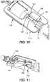
- FIG. 7is another perspective view of the vial supporter of FIG. 6 .
- FIG. 8is a perspective view of a cartridge and/or vial supporter according to another embodiment of the present invention, coupled with a vial adapter and a fillable cartridge.
- FIG. 9is a view of the underside of FIG. 8 .
- FIG. 10is a detail view of the supporter of FIG. 8 .
- FIG. 11is another perspective view of the supporter of FIG. 8 .
- FIG. 12is a perspective view of a cartridge and/or vial supporter according to another embodiment of the present invention, coupled with a vial adapter and a fillable cartridge.
- FIG. 13is an exploded perspective view of the supporter of FIG. 12 .
- FIG. 14is a perspective view of the supporter of FIG. 12 .
- FIG. 15is a perspective view of a vial adapter according to an embodiment of the invention.
- FIG. 16is another perspective view of the vial adapter of FIG. 15 .
- FIG. 17is a cutaway side view of the vial adapter of FIG. 15 .
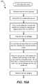
- FIGS. 18A-18Bare a flowchart depicting a method of filling a cartridge using a vial supporter, according to an embodiment of the invention.
- FIGS. 19A-19B and 20A-20Bare perspective views of a cartridge and/or vial supporter according to another embodiment of the present invention.
- FIG. 20Cis a partial cross-sectional view of a portion of the cartridge and/or vial supporter of FIGS. 19A-19B and 20A-20B .
- FIG. 21is a flowchart depicting a method of filling a cartridge using a cartridge and/or vial supporter according to an embodiment of the present invention.
- FIG. 22is a flowchart depicting a method of filling a cartridge using a cartridge and/or vial supporter according to an embodiment of the present invention.
- FIG. 23is a flowchart depicting a method of filling a cartridge using a cartridge and/or vial supporter according to an embodiment of the present invention.
- Described hereinare devices and methods for securely supporting components associated with fillable cartridges for patch pumps.
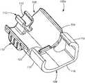
- a system 100which includes a vial supporter 102 a , a cartridge 160 , a fill rod 180 , an adapter 190 , and/or a medicament vial 210 .
- System 100may include all, or less than all of the components depicted in FIGS. 1-4 .
- Vial supporter 102 acan generally include a body portion 104 having a first end 106 , a second end 108 , and one or more features 110 to facilitate grasping vial supporter 102 a by a user during a cartridge filling process and provide a guide as to a desired position to grasp supporter 102 a .
- First end 106includes a cartridge cradle 116 or other suitable means configured for receiving a fillable cartridge 160 , and one or more arms 118 or other suitable means configured for coupling with and supporting cartridge 160 .
- Arms 118are arranged to facilitate easy installation and removal of cartridge 160 while also securely retaining cartridge 160 during filling. As depicted in FIGS. 1-4 , each of arms 118 may be uniquely shaped and sized but in other embodiments arms 118 may be symmetrically shaped and/or size, either with respect to an individual arm 118 or between or among two or more arms, in any combination.
- a stop 120may be included to help locate cartridge 160 in supporter 102 a and prevent movement of cartridge 160 toward second end 108 during, e.g., a cartridge filling process. Vial supporter 102 a may also have one or more features (not pictured) to limit movement of cartridge 160 towards first end 106 during, e.g., a cartridge filling process (when fill rod 180 described below is moved or pulled towards first end 106
- Second end 108may include a cradle 112 configured to couple with and support a tubing section 166 of cartridge 160 .
- cradle 112may be configured to support an interconnect fitting 168 of cartridge 160 in addition to, or instead of, tubing section 166 .
- cradle 112comprises a raised cradle portion defining an aperture or region 113 into which tubing 166 may be snapped or otherwise put in place. The open area defined by edges 113 of the cradle facilitates grasping or otherwise accessing the fitting 168 or tubing 166 when a user wishes to remove them from vial supporter 102 a .
- cradlesmay be utilized, and other configurations of element 112 that support and/or hold tubing section 166 and/or interconnect fitting 168 and facilitate grasping the fitting and tubing are within the scope of the invention.
- Vial supporter 102 ais configured to securely retain and support cartridge 160 such that cartridge 160 can be easily filled.
- Body 162 of cartridge 160is held in cartridge cradle 116 of vial supporter 102 a
- tubing section 166is held in cradle 112 of vial supporter 102 a .
- a fill rod 180is coupleable to cartridge 160
- a vial adapter 190is coupleable to interconnect fitting 168 of cartridge 160 .
- Vial adapter 190facilitates connection between a medicament vial 210 and cartridge 160 . While filling cartridge 160 using vial supporter 102 a , a user need not grasp or hold vial 210 , as vial 210 is sufficiently held in place with vial supporter 102 a.
- vial supporter 102 aprovides a stable and secure arrangement of cartridge 160 , tubing 166 , adapter 190 , and vial 210 , and prevents any misalignment or disconnection between these components while filling cartridge 160 .
- Cartridge 160is depicted in FIG. 5 , and includes body 162 , a reservoir 164 , tubing section 166 and interconnect fitting 168 .
- Cartridge 160 and/or the embodiments of vial supporters described hereincan be configured such that reservoir 164 is visible when cartridge 160 is coupled with a vial supporter, such that a user can determine the level of medicament in cartridge 160 and/or visually inspect for bubbles.
- fitting 168provides a connection for vial 210 .
- fitting 168provides a connection to a medicament administration set (not depicted).
- Cartridge 160also includes a port 170 for fill rod 180 , as best depicted in FIG. 13 .
- Vial supporter 102 bincludes components similar to those in vial supporter 102 a described previously.
- vial supporter 102 bcan generally include a body portion 104 having a first end 106 and a second end 108 .
- First end 106includes a cartridge cradle 116 or other suitable means configured for receiving a fillable cartridge 160 , and one or more arms 118 or other suitable means configured for coupling with and supporting cartridge 160 .
- Arms 118are arranged to facilitate easy installation and removal of cartridge 160 while also securely retaining cartridge 160 during cartridge filling. As depicted in FIGS.
- each of arms 118may be uniquely shaped and sized but in other embodiments arms 118 may be symmetrically shaped and/or sized, either with respect to an individual arm 118 or between or among two or more arms, in any combination.
- a stop(not pictured) may be included to help locate cartridge 160 in supporter 102 b and prevent movement of cartridge 160 toward second end 108 during a cartridge filling process.
- Vial supporter 102 bmay also have one or more features (not pictured) to limit movement of cartridge 160 towards first end 106 during, e.g., a cartridge filling process (when fill rod 180 is moved or pulled towards first end 106 ).
- Second end 108may include a cradle 112 configured to couple with and support an interconnect fitting 168 of cartridge 160 .
- cradle 112may be configured to support a tubing section 166 of cartridge 160 in addition to, or instead of, fitting 168 .
- cradle 112comprises a raised cradle portion defining an aperture or region 113 into which fitting 168 may be snapped or otherwise put in place.
- the open area defined by edges 113 of the cradlefacilitates grasping or otherwise accessing the fitting 168 or tubing 166 when a user wishes to remove them from vial supporter 102 a .
- cradlesmay be utilized, and other configurations of element 112 that support and/or hold tubing section 166 and/or interconnect fitting 168 and facilitate grasping the fitting and tubing are within the scope of the invention.
- Vial supporter 102 bis configured to securely retain and support cartridge 160 such that cartridge 160 can be easily filled.
- Body 162 of cartridge 160is held in cradle 116 of vial supporter 102 b
- tubing section 166is held in cradle 112 of vial supporter 102 b .
- a fill rod 180is coupleable to cartridge 160
- a vial adapter 190is coupleable to interconnect fitting 168 of cartridge 160 .
- Vial adapter 190facilitates connection between a medicament vial 210 and cartridge 160 . While filling cartridge 160 using vial supporter 102 b with medicament, a user need not grasp or hold vial 210 , as vial 210 is sufficiently held in place by vial supporter 102 b.
- fill rod (or plunger handle) 180can generally include a handle portion 182 configured for grasping by a user, a shaft portion 184 , and a threaded portion 186 as depicted in, e.g., FIG. 13 .
- Supporter 102 ccan generally include a tray body 130 having a cartridge end 132 and a vial end 134 , a cartridge holder 136 , a tubing holder 144 , and an interconnect fitting holder 150 .
- Tray body 130is shaped to ease handling during the process of filling a cartridge with medicament and, in some embodiments, is configured to be held by a user in a single hand.
- Cartridge holder 136comprises a recess, channel, cut-out, relief or similar feature into which a cartridge 160 may be at least partially placed or nested.
- Cartridge holder 136is sized and shaped to snugly receive cartridge 160 , including having a perimeter shape generally matching or approximating an outer perimeter shape of the cartridge.
- Cartridge holder 136may also define an aperture or window 140 configured to allow visual inspection of reservoir 164 when cartridge 160 is placed in holder 136 as well as to aid in removal of the cartridge by allowing the user to press on that side of the cartridge to urge the cartridge out of the cartridge holder.
- By visually inspecting cartridge 160either through window 140 or the opposite, fully exposed side of the cartridge, a user can determine whether there are air bubbles in the cartridge that need to be removed.
- the cartridgecan comprise a clear material in the reservoir area where the medicament is contained and can, in some embodiments, include graduated markings delineating volume levels in the reservoir, such that visual inspection can further determine the volume of medicament in the cartridge.
- a ring or other similar retention means 142through which fill rod 180 may be inserted or placed. Ring 142 assists in retaining cartridge 160 securely in place when fill rod 180 is installed because in the depicted embodiment cartridge 160 cannot be removed if the fill rod extends through the ring and is attached to the cartridge.
- Tubing holder 144is configured to retain and support tubing section 166 of cartridge 160 , and can generally include a channel or nest 146 and one or more tabs 148 .
- Channel 146is preferably sized and shaped to provide a secure fit, such as a “snap” fit, with one or more of a reduced diameter portion 169 of interconnect fitting 168 and a portion 167 of cartridge 160 .
- a usermay push down on tab 148 , thereby flexing the material and opening channel 146 , allowing tubing 166 to be removed.
- Interconnect fitting holder 150may comprise a recess or cradle or one or more other configurations and/or features sized and shaped to receive interconnect fitting 168 of cartridge 160 . Furthermore, interconnect fitting holder 150 can have additional features (not shown) to prevent undesirable rotation of the interconnect fitting 168 when, e.g., a user is detaching interconnect fitting 168 from vial adapter 190 (such as, e.g., by unscrewing). In various embodiments, the recess defining interconnect fitting holder 150 may be contiguous and/or continuous with the channel 146 defining tubing holder, which in turn may be contiguous and/or continuous with the recess defining cartridge holder.
- a single continuous recessmay define all of the respective holders, with a varying outer perimeter that matches the shape of the respective component held in each of the holders (additionally optionally including vial adapter holder 151 , discussed below with respect to FIGS. 19-20 ) and/or a varying depth based on the respective component.
- Each of cartridge holder 136 , tubing holder 144 , and interconnect fitting holder 150is configured to provide a user with the ability readily to perform a quick visual and/or tactile confirmation that cartridge 160 and associated components are properly positioned and aligned before beginning a cartridge filling process. While filling cartridge 160 using supporter 102 c , a user need not grasp or hold vial 210 , as vial 210 is sufficiently held in place with supporter 102 c . This results in significant improvement in the user's experience by reducing the complexity and increasing the simplicity of a key aspect of using medicament pumps as described herein.
- Supporter 102 dincludes many components similar to those associated with supporter 102 c described previously.
- supporter 102 dcan generally include a tray body 130 having a cartridge end 132 and a vial end 134 , a cartridge holder 136 , a tubing holder 144 , and an interconnect fitting holder 150 .
- Cartridge holder 136comprises a recess, channel, cut-out, relief or similar feature into which a cartridge 160 may be at least partially placed or nested.
- Cartridge holder 136is sized and shaped to snugly received cartridge 160 .
- Cartridge holder 136may also include an aperture or window 140 which is configured to allow visual inspection of reservoir 164 when cartridge 160 is placed in holder 136 .
- a ring or other similar retention means 142is also included in supporter 102 d through which shaft 184 of fill rod 180 may be inserted or placed. Ring 142 cooperates with fill rod 180 to retain cartridge 160 securely in place when fill rod 180 is installed.
- Tubing holder 144is configured to retain and support tubing section 166 of cartridge 160 , and can generally include a channel or nest 146 and one or more tabs 148 .
- Channel 146is preferably sized and shaped to provide a secure fit with tubing 166 .
- Tabs 148as shown in FIGS. 12-14 can clip over one or more of an end portion 167 of the cartridge 160 and an end portion 169 of the interconnect fitting 168 to securely hold one or both components in place. Downward pressure on tabs 148 can release the components secured therein.
- Interconnect fitting holder 150may comprise a recess or cradle (which may or may not be contiguous with channel or nest 146 ), or other similar configuration which is sized and shaped to receive interconnect fitting 168 of cartridge 160 .
- the fitting holder 150can be shaped to prevent turning of the interconnect fitting 168 when it is disposed in the fitting holder 150 .
- Each of cartridge holder 136 , tubing holder 144 , and interconnect fitting holder 150is configured to provide a user with the ability readily to perform a quick visual and/or tactile confirmation that cartridge 160 and associated components are properly positioned and aligned before beginning a cartridge filling process. This results in significant improvement in the user's experience and reduces the complexity and simplicity of a key aspect of using medicament pumps as described herein. While filling cartridge 160 using supporter 102 d , a user need not grasp or hold vial 210 , as vial 210 is sufficiently held in place with supporter 102 d.
- FIGS. 15-17an embodiment of a vial adapter 190 is depicted.
- This embodimentcan generally include a vial end 192 , and a cartridge end 202 , a bore 194 for receiving vial 210 , a retention feature 196 disposed within bore 194 , a needle 198 for puncturing vial 210 and allowing fluid such as medicament to flow therethrough, and one or more reliefs 200 .
- Cartridge end 202includes a vial adapter fitting 204 configured for coupling to the fitting 168 of cartridge 160 and a bore 206 which may be straight or tapered so to improve sealing when vial adapter 190 is coupled with fitting 168 .
- Fitting 204may be a Luer-type fitting, a proprietary fitting, or other desired style of fitting.
- vial 210is placed into bore 194 , engaging with retention feature 196 .
- Reliefs 200allow vial adapter 190 to flex slightly when vial 210 is installed or removed, thus facilitating secure use.
- FIGS. 19A-19B and 20A-20Bdepict another embodiment of a cartridge and/or vial supporter 102 e .
- supporter 102 eis configured with a tray body 130 having a cartridge end 132 and a vial end 134 .
- Tray body 130includes cartridge holder 136 configured to contain a cartridge 160 therein, a tubing holder 144 and a fitting holder 150 .
- cartridge holder 136configured to contain a cartridge 160 therein, a tubing holder 144 and a fitting holder 150 .
- Each of these componentsis configured and functions substantially similarly to the embodiments described above.
- tray 130includes a vial adapter holder 151 defined by a recess, channel, cut-out, relief or similar feature at vial end 134 of trail body 130 adjacent fitting holder 150 and adapted to receive a fitting end 191 of a vial adapter 190 . Because fitting end 191 of vial adapter 190 is configured to connect to the interconnect fitting 168 of cartridge, vial adapter holder 151 will generally be positioned adjacent the fitting holder 150 at vial end 134 of tray body 130 . In some embodiments, vial adapter holder 151 can be formed contiguously and/or continuously with interconnect fitting holder 150 .
- vial adapter holder 151can be provided with a configuration that prevents rotation of vial adapter 190 and thereby prevents unscrewing of fitting end 191 of the vial adapter 190 from cartridge fitting 168 when the components are nested in the tray body 130 .
- fitting end 191 of the vial adapteris provided with a hexagonal configuration and vial adapter holder 151 has a corresponding partial-hexagonal shape matching the configuration of the fitting end to prevent such rotation, but in other embodiments any other matching shapes that prevent rotation could be used.
- a fitting retention tab 148interfaces with interconnect fitting 168 to retain the fitting in the tray body 130 .
- Fitting 168can be press fit into fitting holder 150 to form an audible “snap” fit as described above with fitting retention tab 148 physically engaging fitting 168 to hold fitting 168 in fitting holder 150 . This physical engagement can then be released by pressing on fitting retention tab 148 to enable removal of fitting 168 from fitting holder 150 .
- This embodimentalso includes a cartridge retention tab 149 , which can be seen in the partial cross-sectional view of FIG. 20C . When cartridge 130 is inserted into cartridge holder 136 , a bottom wall portion 147 of cartridge is seated beneath cartridge retention tab 149 .
- Cartridge 160can be removed by first tilting the opposite end of cartridge 160 (adjacent the tubing portion 144 ) upward, and then sliding bottom wall portion 147 away from cartridge retention tab 149 .
- Fitting retention tab or tabs 148 , along with cartridge holder 136 and cartridge retention tab 149 and/or the combination of fill rod 180 and ring 142 (in embodiments described above),generally prevent both forward and backward movement and upward movement of the components contained in tray body 130 during the cartridge filling process.
- cartridge 160further includes a fitting cap 161 .
- plug 165 of fitting cap 161can be inserted onto cartridge fitting 168 by pressing or rotating cap 163 of fitting cap 161 after the cartridge has been filled with medicament and removed from supporter 102 e to seal the cartridge to prevent leakage of medicament if the cartridge is going to be stored and not immediately connected to a pump.
- Supporter 102 ealso provides a fitting cap holder 153 that includes a recess 155 into which cap 163 of fitting cap 161 fits and a slot 157 into which plug 165 of fitting cap 161 is received.
- a portion of plug 165as shown in FIG.
- fitting cap 161extends through supporter 102 e such that fitting cap 161 can be removed from supporter 102 e by a user pushing down on plug 165 from that side.
- the capis generally provided loosely in the system packaging and, as such, can easily fall out and become lost, contaminated, etc. upon opening the packaging.
- One advantage of having a fitting cap holder 153 in the tray body 130 in embodiments of the present inventionis that when the device is initially removed from the packaging, the fitting cap 161 is secured to the tray body and can therefore be both easily located for use and prevented from falling out.
- a method 208 for filling a medicament cartridge of an ambulatory, user-wearable infusion pumpincludes coupling the cartridge to a vial supporter and to a vial.
- Example vial supporters suitable for use with such a methodare depicted in FIGS. 1-4 and 6-7 .
- the vialcan be removed from the adapter, and the adapted removed from the interconnect fitting of the cartridge.
- the cartridgecan then be attached to an infusion set, and the fill rod and vial supporter are uncoupled from the cartridge and placed aside until the cartridge needs to be filled again.
- Method 210includes connecting a vial adapter to an interconnect fitting of a medicament cartridge at step 212 , such as shown in, for example, FIG. 13 .
- the cartridge, including a tubing portion extending from cartridge and the interconnect fitting, and connected vial adaptercan then be seated in a supporter configured as a tray at step 214 as described above.
- the traycan include recessed holders defined therein that are sized and shaped to receive the cartridge, tubing portion and interconnect fitting.
- the trayalso includes a vial adapter holder that retains a portion of the vial adapter.
- one or more of a portion of cartridge and a portion of interconnect fittingcan create a snap fit with one or more tabs on tray to aid in retaining those components in the tray.
- a fill rodcan then be inserted through a portion of the tray and connected to the cartridge at step 216 , although in the embodiment depicted in FIGS. 19A-19B and 20A-20C the fill rod can be inserted either prior to or after seating the cartridge in the cartridge holder. Such a seated configuration is shown in, for example, FIGS. 8-12 and 19-20 .
- the systemmay come pre-packaged in this configuration before initial use of the cartridge. When the cartridge is refilled, steps 212 - 216 must be repeated.
- the fill rodcan be positioned to set a desired fill volume.
- a vial containing the medicament that is to be infused into the cartridgecan then be attached to the vial adapter at step 220 , though it should be noted that the vial could alternatively be connected to the vial adapter at any earlier portion of the method.
- the cartridgecan then be filled with the desired volume of the medicament at step 222 and the vial removed.
- filling the cartridgecan include depressing the fill rod to push air into the cartridge, then retracting the fill rod to fill the cartridge with the desired amount, and then checking for air bubbles in the cartridge before removing the vial.
- the cartridgecan comprise a clear material in the reservoir area where the medicament is contained and the tray can include a rear opening, such as opening 140 described above, to aid in inspecting the cartridge for air bubbles as well as observing the volume of medicament in the cartridge.
- the cartridge, fill rod and vial adaptercan be removed from the tray at step 224 .
- the cartridge removalcan be aided by one or more tabs that release portions of the system that were snap fit into the tray as described above.
- this openingcan further aid in cartridge removal by providing easy access for the user to press on the cartridge to push it out of the tray. It should be noted that in embodiments such as those depicted in FIGS.
- fill rod 180must first be removed prior to removing the cartridge and vial adapter. Following removal of the cartridge from the tray, the vial adapter can be disconnected from the interconnect fitting at step 226 .
- the cartridgeis now filled and is readied for use by pushing the fill rod so that a drop of medicament such as insulin is visible at the top of the interconnect fitting and an infusion set attached to interconnect fitting at step 228 .
- the fill rodcan then be removed at step 230 .
- the cartridgecan now be attached to a user-wearable, ambulatory infusion pump at step 232 .
- a fitting capsuch as fitting cap 161 can be inserted into interconnect fitting of cartridge rather than attaching the fitting to an infusion set to preclude accidental leakage of fluid from cartridge.
- FIG. 22a method 240 for filling a medicament cartridge of an ambulatory, user-wearable infusion pump according to another embodiment is depicted and described.
- the depicted methodis suitable for use with, for example, the cartridge and/or vial supporters shown in FIGS. 8-11, 12-14 and 19A-20C .
- tray body 130 , vial adapter 190 and cartridge 160 (and fill rod 180 )are provided to the user pre-assembled.
- the userremoves this pre-assembled combination from the product packaging, sets the desired fill volume with the fill rod at step 243 and connects a medicament vial to the vial adapter at step 244 .
- the cartridgeAfter pushing air into the medicament vial with the fill rod at step 245 , the cartridge is then filled with medicament at step 246 as described above and the vial removed from the vial adapter at step 248 .
- the cartridge and vial adaptercan then be removed from the tray at step 250 followed by removal of the vial adapter from the cartridge at step 252 .
- the fill rodis then pushed so that a drop of medicament such as insulin is visible at the tip of the fitting at step 254 and the fill rod removed from the cartridge at step 256 as described above.
- the filled cartridgecan now be attached to the pump or stored for later use at step 258 .
- FIG. 23depicts another method 270 for filling a medicament cartridge of an ambulatory, user-wearable infusion pump according to an embodiment of the infusion with a cartridge and/or vial supporter configured as a tray.
- the usermust assemble the cartridge components for filling. Such a procedure may occur when a user is refilling a cartridge after one or more initial uses.
- the vial adapteris connected to the interconnect fitting of the cartridge and at step 274 the fill rod is connected to the cartridge. This assembly can then be placed into the cartridge tray at step 276 .
- the fill rodcan be set for a desired fill volume at 277 and the medicament vial can be connected to the vial adapter at step 278 . Air can be pushed into the medicament vial with the fill rod at step 279 and the cartridge filled with medicament at step 280 . The medicament vial is then removed from the vial adapter at step 282 and the cartridge assembly removed from the tray at step 284 . The filled cartridge can then be readied for use as described previously by removing the vial adapter from the interconnect fitting at step 286 , pushing the fill rod so that a drop of medicament such as insulin is visible at the tip of the fitting at step 288 and removing the fill rod at step 290 . The filled cartridge is now ready to be attached to a pump (and infusion set) or stored for later use, as described herein, at step 292 .
Landscapes
- Health & Medical Sciences (AREA)
- Veterinary Medicine (AREA)
- Life Sciences & Earth Sciences (AREA)
- Animal Behavior & Ethology (AREA)
- General Health & Medical Sciences (AREA)
- Public Health (AREA)
- Hematology (AREA)
- Engineering & Computer Science (AREA)
- Vascular Medicine (AREA)
- Anesthesiology (AREA)
- Biomedical Technology (AREA)
- Heart & Thoracic Surgery (AREA)
- Pharmacology & Pharmacy (AREA)
- Mechanical Engineering (AREA)
- Infusion, Injection, And Reservoir Apparatuses (AREA)
- Medical Preparation Storing Or Oral Administration Devices (AREA)
Abstract
Description
Claims (19)
Priority Applications (3)
| Application Number | Priority Date | Filing Date | Title |
|---|---|---|---|
| US15/705,983US10926025B2 (en) | 2016-09-15 | 2017-09-15 | Vial supporter for medicament pump |
| US17/181,808US12263324B2 (en) | 2016-09-15 | 2021-02-22 | Vial supporter for medicament pump |
| US19/066,419US20250195748A1 (en) | 2016-09-15 | 2025-02-28 | Vial supporter for medicament pump |
Applications Claiming Priority (2)
| Application Number | Priority Date | Filing Date | Title |
|---|---|---|---|
| US201662394806P | 2016-09-15 | 2016-09-15 | |
| US15/705,983US10926025B2 (en) | 2016-09-15 | 2017-09-15 | Vial supporter for medicament pump |
Related Child Applications (1)
| Application Number | Title | Priority Date | Filing Date |
|---|---|---|---|
| US17/181,808ContinuationUS12263324B2 (en) | 2016-09-15 | 2021-02-22 | Vial supporter for medicament pump |
Publications (2)
| Publication Number | Publication Date |
|---|---|
| US20180071454A1 US20180071454A1 (en) | 2018-03-15 |
| US10926025B2true US10926025B2 (en) | 2021-02-23 |
Family
ID=61558996
Family Applications (3)
| Application Number | Title | Priority Date | Filing Date |
|---|---|---|---|
| US15/705,983Active2037-12-19US10926025B2 (en) | 2016-09-15 | 2017-09-15 | Vial supporter for medicament pump |
| US17/181,808Active2039-09-25US12263324B2 (en) | 2016-09-15 | 2021-02-22 | Vial supporter for medicament pump |
| US19/066,419PendingUS20250195748A1 (en) | 2016-09-15 | 2025-02-28 | Vial supporter for medicament pump |
Family Applications After (2)
| Application Number | Title | Priority Date | Filing Date |
|---|---|---|---|
| US17/181,808Active2039-09-25US12263324B2 (en) | 2016-09-15 | 2021-02-22 | Vial supporter for medicament pump |
| US19/066,419PendingUS20250195748A1 (en) | 2016-09-15 | 2025-02-28 | Vial supporter for medicament pump |
Country Status (1)
| Country | Link |
|---|---|
| US (3) | US10926025B2 (en) |
Cited By (4)
| Publication number | Priority date | Publication date | Assignee | Title |
|---|---|---|---|---|
| US20210178054A1 (en)* | 2016-09-15 | 2021-06-17 | Tandem Diabetes Care, Inc. | Vial supporter for medicament pump |
| US11305057B2 (en) | 2019-03-26 | 2022-04-19 | Tandem Diabetes Care, Inc. | Method and system of operating an infusion pump with a remote control device |
| US11984223B2 (en) | 2019-02-19 | 2024-05-14 | Tandem Diabetes Care, Inc. | System and method of pairing an infusion pump with a remote control device |
| US12343496B2 (en) | 2015-05-18 | 2025-07-01 | Tandem Diabetes Care, Inc | Patch pump cartridge attachment |
Families Citing this family (12)
| Publication number | Priority date | Publication date | Assignee | Title |
|---|---|---|---|---|
| US9238100B2 (en) | 2012-06-07 | 2016-01-19 | Tandem Diabetes Care, Inc. | Device and method for training users of ambulatory medical devices |
| US10279106B1 (en) | 2014-05-08 | 2019-05-07 | Tandem Diabetes Care, Inc. | Insulin patch pump |
| US10279107B2 (en) | 2015-08-20 | 2019-05-07 | Tandem Diabetes Care, Inc. | Drive mechanism for infusion pump |
| US10576207B2 (en) | 2015-10-09 | 2020-03-03 | West Pharma. Services IL, Ltd. | Angled syringe patch injector |
| JP6885960B2 (en) | 2016-01-21 | 2021-06-16 | ウェスト ファーマ サービシーズ イスラエル リミテッド | Drug delivery device with visual indicators |
| WO2018132578A1 (en) | 2017-01-11 | 2018-07-19 | Tandem Diabetes Care, Inc. | Electromagnetic signal-based infusion pump control |
| CN111936182B (en) | 2018-02-05 | 2022-08-23 | 坦德姆糖尿病护理股份有限公司 | Method and system for detecting the condition of an infusion pump |
| JP7323624B2 (en)* | 2018-09-11 | 2023-08-08 | ウェスト ファーマ サービシーズ イスラエル リミテッド | Extension used to fill pharmaceutical syringe cartridges |
| US11464908B2 (en) | 2019-02-18 | 2022-10-11 | Tandem Diabetes Care, Inc. | Methods and apparatus for monitoring infusion sites for ambulatory infusion pumps |
| US12138425B2 (en) | 2019-05-21 | 2024-11-12 | Tandem Diabetes Care, Inc. | System and method for incorporating exercise into closed-loop diabetes therapy |
| GB2591477B (en) | 2020-01-29 | 2023-02-15 | Aspen Pumps Ltd | A bracket for securing a device |
| US20250108162A1 (en) | 2023-09-29 | 2025-04-03 | Tandem Diabetes Care, Inc. | Infusion pump with multi-cgm compatibility |
Citations (84)
| Publication number | Priority date | Publication date | Assignee | Title |
|---|---|---|---|---|
| US2077240A (en)* | 1935-11-14 | 1937-04-13 | Clyde R Jeffords | Hypodermic outfit case |
| US2627857A (en)* | 1949-07-21 | 1953-02-10 | Marcelli Attilio | Syringe holder |
| US3245194A (en)* | 1962-07-31 | 1966-04-12 | B D Lab Inc | Method and apparatus for filling hypodermic syringes, ampules, etc. |
| US3734147A (en)* | 1971-03-17 | 1973-05-22 | Sherwood Medical Ind Inc | Manual syringe filling apparatus |
| US3833030A (en)* | 1973-03-05 | 1974-09-03 | E Flippo | Device for withdrawing or adding fluids to hypodermic syringes |
| US3853158A (en)* | 1973-02-05 | 1974-12-10 | Sinai Hospital Of Detroit | Apparatus for inserting a syringe needle into a vial |
| US3875979A (en)* | 1973-02-14 | 1975-04-08 | Wayne P Hults | Medication metering device |
| US3940909A (en)* | 1973-08-21 | 1976-03-02 | Elisabetta Cioni | Machine for filling and sealing glass vials starting from closed vials |
| US4516967A (en)* | 1981-12-21 | 1985-05-14 | Kopfer Rudolph J | Wet-dry compartmental syringe |
| US4883101A (en)* | 1988-06-27 | 1989-11-28 | Jordan Enterprises | Filling device with sound indicator for filling injection syringe |
| US5292318A (en)* | 1991-08-07 | 1994-03-08 | Habley Medical Technology Corporation | Syringe filling and metering device for pharmaceutical containers |
| US5334162A (en)* | 1993-03-15 | 1994-08-02 | Eli Lilly And Company | Cartridge assembly for a lyophilized compound forming a disposable portion of an injector pen and method for same |
| US5468233A (en)* | 1993-12-06 | 1995-11-21 | Schraga; Steven | Hypodermic dosage measuring device |
| US5478211A (en)* | 1994-03-09 | 1995-12-26 | Baxter International Inc. | Ambulatory infusion pump |
| US5584814A (en)* | 1995-01-26 | 1996-12-17 | Schuster; John H. | Syringe actuation system |
| US5743312A (en)* | 1995-04-11 | 1998-04-28 | Behringwerke Aktiengesellschaft | Component mixing apparatus and system including a movable cannula |
| US5827262A (en)* | 1993-09-07 | 1998-10-27 | Debiotech S.A. | Syringe device for mixing two compounds |
| US5858001A (en) | 1995-12-11 | 1999-01-12 | Elan Medical Technologies Limited | Cartridge-based drug delivery device |
| US5894870A (en)* | 1997-06-10 | 1999-04-20 | Pharmacia & Upjohn Company | Syringe guide and vial holder |
| US5911252A (en)* | 1997-04-29 | 1999-06-15 | Cassel; Douglas | Automated syringe filling system for radiographic contrast agents and other injectable substances |
| US6006798A (en)* | 1998-10-09 | 1999-12-28 | Lindquist; Barbara J. | Syringe loading jig |
| US6146361A (en) | 1996-09-26 | 2000-11-14 | Becton Dickinson And Company | Medication delivery pen having a 31 gauge needle |
| US6364866B1 (en)* | 1999-01-22 | 2002-04-02 | Douglas Furr | Syringe loading aid |
| US20020049405A1 (en)* | 2000-10-19 | 2002-04-25 | Deslauriers Richard J. | Device and method for mixing a two-part composition forming synthetic bone |
| US6439276B1 (en)* | 2001-07-06 | 2002-08-27 | Trimensions, Inc. | Kit for loading and disposal of hypodermic syringes used for administering medication |
| US20030100866A1 (en)* | 2001-11-23 | 2003-05-29 | Duoject Medical Systems Inc. | System for filling and assembling pharmaceutical delivery devices |
| US20030199847A1 (en)* | 2002-04-17 | 2003-10-23 | Roger Akerlund | Method and device for fluid transfer in an infusion system |
| US6648859B2 (en) | 1997-09-29 | 2003-11-18 | Becton Dickinson And Company | Disposable, pre-filled drug cartridge |
| US6649403B1 (en) | 2000-01-31 | 2003-11-18 | Board Of Regents, The University Of Texas Systems | Method of preparing a sensor array |
| US20030216683A1 (en) | 2001-11-26 | 2003-11-20 | Nili-Med Ltd. | Drug delivery device and method |
| US20040069044A1 (en)* | 1999-04-29 | 2004-04-15 | Gilad Lavi | Device for measuring a volume of drug |
| US20050087256A1 (en)* | 2003-10-23 | 2005-04-28 | Niles Clark | Method and apparatus for filling syringes |
| US20050092387A1 (en)* | 2003-10-31 | 2005-05-05 | Gregory Schorn | Refill kit for an implantable pump |
| US7033338B2 (en) | 2002-02-28 | 2006-04-25 | Smiths Medical Md, Inc. | Cartridge and rod for axially loading medication pump |
| US7041082B2 (en) | 2002-02-28 | 2006-05-09 | Smiths Medical Md, Inc. | Syringe pump control systems and methods |
| US20060206054A1 (en) | 2001-11-26 | 2006-09-14 | Nilimedix Ltd. | Drug delivery device and method |
| US7195616B2 (en) | 2001-05-16 | 2007-03-27 | Eli Lilly And Company | Medication injector apparatus with drive assembly that facilitates reset |
| US20070088267A1 (en) | 2004-05-30 | 2007-04-19 | Avraham Shekalim | Drug delivery device and method |
| US20070156092A1 (en) | 2005-09-26 | 2007-07-05 | M2 Medical A/S | Operating an Infusion Pump System |
| US7291132B2 (en) | 2003-08-12 | 2007-11-06 | Eli Lilly And Company | Medication dispensing apparatus with triple screw threads for mechanical advantage |
| US20080051711A1 (en) | 2006-08-23 | 2008-02-28 | Medtronic Minimed, Inc. | Infusion medium delivery device and method with drive device for driving plunger in reservoir |
| US20080051697A1 (en) | 2006-08-23 | 2008-02-28 | Medtronic Minimed, Inc. | Infusion medium delivery device and method with compressible or curved reservoir or conduit |
| US20080051727A1 (en) | 2006-08-23 | 2008-02-28 | Medtronic Minimed, Inc. | Infusion medium delivery device and method with drive device for driving plunger in reservoir |
| US20080215035A1 (en) | 2006-12-22 | 2008-09-04 | Medingo, Ltd. | Systems, devices and methods for sustained delivery of a therapeutic fluid |
| US20080306439A1 (en)* | 2007-06-08 | 2008-12-11 | Nelson M Bud | Devices for mixing and applying a fluid composition |
| WO2009013736A1 (en) | 2007-07-20 | 2009-01-29 | Medingo Ltd. | Manually operable portable infusion device |
| WO2009016636A2 (en) | 2007-08-01 | 2009-02-05 | Medingo Ltd. | Portable infusion device provided with means for monitoring and controlling fluid delivery |
| US20090036870A1 (en) | 2006-08-23 | 2009-02-05 | Medtronic Minimed, Inc. | Infusion medium delivery device and method with drive device for driving plunger in reservoir |
| US20090275887A1 (en) | 2008-05-05 | 2009-11-05 | M2 Medical Group Holdings, Inc. | Infusion Pump System |
| US7651868B2 (en) | 2003-12-11 | 2010-01-26 | The Board Of Regents Of The University Of Texas System | Method and system for the analysis of saliva using a sensor array |
| US20100049164A1 (en) | 2008-08-20 | 2010-02-25 | M2 Medical Group Holdings, Inc. | Infusion Pump Systems and Methods |
| US7678084B2 (en) | 2002-03-18 | 2010-03-16 | Eli Lilly And Company | Medication dispensing apparatus with gear set for mechanical advantage |
| US7695454B2 (en) | 2003-10-16 | 2010-04-13 | Eli Lilly And Company | Fixed dose medication dispensing device |
| US20100094251A1 (en) | 2008-10-15 | 2010-04-15 | M2 Medical Group Holdings, Inc. | Infusion Pump System and Methods |
| US7704237B2 (en) | 2001-07-16 | 2010-04-27 | Eli Lilly And Company | Medication dispensing apparatus configured for rotate to prime and pull/push to inject functionality |
| US20100174266A1 (en) | 2009-01-02 | 2010-07-08 | M2 Medical Group Holdings, Inc. | Infusion Pump System and Methods |
| US20100191182A1 (en)* | 2007-04-27 | 2010-07-29 | Amylin Pharmaceuticals, Inc | Mixing Tool |
| US20100262078A1 (en) | 2009-03-31 | 2010-10-14 | Smiths Medical Asd, Inc. | Systems and methods to address air, leaks and occlusions in an insulin pump system |
| US7857791B2 (en) | 2004-03-30 | 2010-12-28 | Eli Lilly And Company | Medication dispensing apparatus with gear set having drive member accommodating opening |
| US20110004143A1 (en)* | 2009-07-01 | 2011-01-06 | Michael James Beiriger | Drug Delivery Devices And Related Systems And Methods |
| US20110004188A1 (en) | 2008-02-04 | 2011-01-06 | Avraham Shekalim | Drug delivery system with wireless monitor |
| US20110106045A1 (en)* | 2009-10-30 | 2011-05-05 | Reynolds David L | Inter vial transfer system |
| US7981076B2 (en) | 2004-09-10 | 2011-07-19 | Becton, Dickinson And Company | Reconstituting infusion device |
| US20110213329A1 (en) | 2008-11-11 | 2011-09-01 | Ofer Yodfat | Modular Fluid Delivery Device with Quick-Release / Connect Mechanism for Drive Screw |
| US20120160723A1 (en)* | 2009-03-31 | 2012-06-28 | Sanofi-Aventis Deutschland Gmbh | Fixing Means |
| US8234126B1 (en) | 2008-02-12 | 2012-07-31 | Asante Solutions, Inc. | Distribution of infusion pumps |
| US20120226238A1 (en)* | 2009-06-02 | 2012-09-06 | Sanofi-Aventis Deutschland Gmbh | Medicated module with bypass and needle guard |
| US8287495B2 (en) | 2009-07-30 | 2012-10-16 | Tandem Diabetes Care, Inc. | Infusion pump system with disposable cartridge having pressure venting and pressure feedback |
| US20130053816A1 (en) | 2011-07-25 | 2013-02-28 | Tandem Diabetes Care, Inc. | Multi-reservoir infusion pump systems and methods |
| US8573027B2 (en) | 2009-02-27 | 2013-11-05 | Tandem Diabetes Care, Inc. | Methods and devices for determination of flow reservoir volume |
| US20130324928A1 (en) | 2012-06-05 | 2013-12-05 | Tandem Diabetes Care, Inc. | Infusion pump system with disposable cartridge having pressure venting and pressure feedback |
| US20130331790A1 (en) | 2012-06-07 | 2013-12-12 | Tandem Diabetes Care, Inc. | Sealed infusion device with electrical connector port |
| US20140276423A1 (en) | 2013-03-14 | 2014-09-18 | Tandem Diabetes Care, Inc. | Infusion system and methods |
| US20140378898A1 (en) | 2013-06-21 | 2014-12-25 | Tandem Diabetes Care, Inc. | System and method for infusion set dislodgement detection |
| US20150029816A1 (en)* | 2012-03-09 | 2015-01-29 | Sensile Pat Ag | Drug reconstitution system |
| US8986253B2 (en) | 2008-01-25 | 2015-03-24 | Tandem Diabetes Care, Inc. | Two chamber pumps and related methods |
| US20150182693A1 (en) | 2013-12-26 | 2015-07-02 | Tandem Diabetes Care, Inc. | System and method for modifying medicament delivery parameters after a site change |
| WO2015115435A1 (en)* | 2014-01-30 | 2015-08-06 | テルモ株式会社 | Liquid medicine filling unit, liquid medicine reservoir instrument, and filling adapter |
| US20160339172A1 (en) | 2015-05-18 | 2016-11-24 | Tandem Diabetes Care, Inc. | Patch pump cartridge attachment |
| US20170028132A1 (en)* | 2013-12-01 | 2017-02-02 | Becton, Dickinson And Company | Medicament Device |
| US20170049957A1 (en) | 2015-08-20 | 2017-02-23 | Tandem Diabetes Care, Inc. | Drive mechanism for infusion pump |
| US20170112997A1 (en) | 2012-05-17 | 2017-04-27 | Tandem Diabetes Care, Inc. | Methods and devices for multiple fluid transfer |
| US20170129763A1 (en)* | 2014-07-14 | 2017-05-11 | Icu Medical, Inc. | Fluid transfer devices and methods of use |
| US20170135903A1 (en)* | 2014-01-29 | 2017-05-18 | Eveon | Device for reconstituting a pharmaceutical composition |
Family Cites Families (3)
| Publication number | Priority date | Publication date | Assignee | Title |
|---|---|---|---|---|
| US8360114B2 (en)* | 2003-10-23 | 2013-01-29 | Niles Clark | Apparatus and method for filing a syringe |
| US9044542B2 (en)* | 2007-12-21 | 2015-06-02 | Carticept Medical, Inc. | Imaging-guided anesthesia injection systems and methods |
| US10926025B2 (en)* | 2016-09-15 | 2021-02-23 | Tandem Diabetes Care, Inc. | Vial supporter for medicament pump |
- 2017
- 2017-09-15USUS15/705,983patent/US10926025B2/enactiveActive
- 2021
- 2021-02-22USUS17/181,808patent/US12263324B2/enactiveActive
- 2025
- 2025-02-28USUS19/066,419patent/US20250195748A1/enactivePending
Patent Citations (107)
| Publication number | Priority date | Publication date | Assignee | Title |
|---|---|---|---|---|
| US2077240A (en)* | 1935-11-14 | 1937-04-13 | Clyde R Jeffords | Hypodermic outfit case |
| US2627857A (en)* | 1949-07-21 | 1953-02-10 | Marcelli Attilio | Syringe holder |
| US3245194A (en)* | 1962-07-31 | 1966-04-12 | B D Lab Inc | Method and apparatus for filling hypodermic syringes, ampules, etc. |
| US3734147A (en)* | 1971-03-17 | 1973-05-22 | Sherwood Medical Ind Inc | Manual syringe filling apparatus |
| US3853158A (en)* | 1973-02-05 | 1974-12-10 | Sinai Hospital Of Detroit | Apparatus for inserting a syringe needle into a vial |
| US3875979A (en)* | 1973-02-14 | 1975-04-08 | Wayne P Hults | Medication metering device |
| US3833030A (en)* | 1973-03-05 | 1974-09-03 | E Flippo | Device for withdrawing or adding fluids to hypodermic syringes |
| US3940909A (en)* | 1973-08-21 | 1976-03-02 | Elisabetta Cioni | Machine for filling and sealing glass vials starting from closed vials |
| US4516967A (en)* | 1981-12-21 | 1985-05-14 | Kopfer Rudolph J | Wet-dry compartmental syringe |
| US4883101A (en)* | 1988-06-27 | 1989-11-28 | Jordan Enterprises | Filling device with sound indicator for filling injection syringe |
| US5292318A (en)* | 1991-08-07 | 1994-03-08 | Habley Medical Technology Corporation | Syringe filling and metering device for pharmaceutical containers |
| US5334162A (en)* | 1993-03-15 | 1994-08-02 | Eli Lilly And Company | Cartridge assembly for a lyophilized compound forming a disposable portion of an injector pen and method for same |
| US5827262A (en)* | 1993-09-07 | 1998-10-27 | Debiotech S.A. | Syringe device for mixing two compounds |
| US5468233A (en)* | 1993-12-06 | 1995-11-21 | Schraga; Steven | Hypodermic dosage measuring device |
| US5478211A (en)* | 1994-03-09 | 1995-12-26 | Baxter International Inc. | Ambulatory infusion pump |
| US5584814A (en)* | 1995-01-26 | 1996-12-17 | Schuster; John H. | Syringe actuation system |
| US5743312A (en)* | 1995-04-11 | 1998-04-28 | Behringwerke Aktiengesellschaft | Component mixing apparatus and system including a movable cannula |
| US5858001A (en) | 1995-12-11 | 1999-01-12 | Elan Medical Technologies Limited | Cartridge-based drug delivery device |
| US6146361A (en) | 1996-09-26 | 2000-11-14 | Becton Dickinson And Company | Medication delivery pen having a 31 gauge needle |
| US5911252A (en)* | 1997-04-29 | 1999-06-15 | Cassel; Douglas | Automated syringe filling system for radiographic contrast agents and other injectable substances |
| US5894870A (en)* | 1997-06-10 | 1999-04-20 | Pharmacia & Upjohn Company | Syringe guide and vial holder |
| US6648859B2 (en) | 1997-09-29 | 2003-11-18 | Becton Dickinson And Company | Disposable, pre-filled drug cartridge |
| US6006798A (en)* | 1998-10-09 | 1999-12-28 | Lindquist; Barbara J. | Syringe loading jig |
| US6364866B1 (en)* | 1999-01-22 | 2002-04-02 | Douglas Furr | Syringe loading aid |
| US20040069044A1 (en)* | 1999-04-29 | 2004-04-15 | Gilad Lavi | Device for measuring a volume of drug |
| US7316899B2 (en) | 2000-01-31 | 2008-01-08 | The Board Of Regents Of The University Of Texas System | Portable sensor array system |
| US6649403B1 (en) | 2000-01-31 | 2003-11-18 | Board Of Regents, The University Of Texas Systems | Method of preparing a sensor array |
| US20020049405A1 (en)* | 2000-10-19 | 2002-04-25 | Deslauriers Richard J. | Device and method for mixing a two-part composition forming synthetic bone |
| US7704238B2 (en) | 2001-05-16 | 2010-04-27 | Eli Lilly And Company | Medication injector apparatus with drive assembly that facilitates reset |
| US7195616B2 (en) | 2001-05-16 | 2007-03-27 | Eli Lilly And Company | Medication injector apparatus with drive assembly that facilitates reset |
| US6439276B1 (en)* | 2001-07-06 | 2002-08-27 | Trimensions, Inc. | Kit for loading and disposal of hypodermic syringes used for administering medication |
| US7704237B2 (en) | 2001-07-16 | 2010-04-27 | Eli Lilly And Company | Medication dispensing apparatus configured for rotate to prime and pull/push to inject functionality |
| US20030100866A1 (en)* | 2001-11-23 | 2003-05-29 | Duoject Medical Systems Inc. | System for filling and assembling pharmaceutical delivery devices |
| US7291126B2 (en) | 2001-11-26 | 2007-11-06 | Nilimedix Ltd. | Drug delivery device and method |
| US7311693B2 (en) | 2001-11-26 | 2007-12-25 | Nilimedix Ltd. | Drug delivery device and method |
| US20060206054A1 (en) | 2001-11-26 | 2006-09-14 | Nilimedix Ltd. | Drug delivery device and method |
| US20030216683A1 (en) | 2001-11-26 | 2003-11-20 | Nili-Med Ltd. | Drug delivery device and method |
| US7033338B2 (en) | 2002-02-28 | 2006-04-25 | Smiths Medical Md, Inc. | Cartridge and rod for axially loading medication pump |
| US7905859B2 (en) | 2002-02-28 | 2011-03-15 | Smiths Medical Asd, Inc. | Pump with venting |
| US20070161955A1 (en) | 2002-02-28 | 2007-07-12 | Smiths Medical Md, Inc. | Pump with Venting |
| US7442186B2 (en) | 2002-02-28 | 2008-10-28 | Smiths Medical Md, Inc. | Syringe pump control systems using a light sensor |
| US7510544B2 (en) | 2002-02-28 | 2009-03-31 | Smiths Medical Md, Inc. | Cartridge and pump with axial loading |
| US7041082B2 (en) | 2002-02-28 | 2006-05-09 | Smiths Medical Md, Inc. | Syringe pump control systems and methods |
| US7678084B2 (en) | 2002-03-18 | 2010-03-16 | Eli Lilly And Company | Medication dispensing apparatus with gear set for mechanical advantage |
| US20030199847A1 (en)* | 2002-04-17 | 2003-10-23 | Roger Akerlund | Method and device for fluid transfer in an infusion system |
| US20120017688A1 (en) | 2003-05-29 | 2012-01-26 | Nili-Med Ltd. | Drug delivery device and method |
| US7291132B2 (en) | 2003-08-12 | 2007-11-06 | Eli Lilly And Company | Medication dispensing apparatus with triple screw threads for mechanical advantage |
| US7427275B2 (en) | 2003-08-12 | 2008-09-23 | Eli Lilly And Company | Medication dispensing apparatus with triple screw threads for mechanical advantage |
| US7695454B2 (en) | 2003-10-16 | 2010-04-13 | Eli Lilly And Company | Fixed dose medication dispensing device |
| US20050087256A1 (en)* | 2003-10-23 | 2005-04-28 | Niles Clark | Method and apparatus for filling syringes |
| US20050092387A1 (en)* | 2003-10-31 | 2005-05-05 | Gregory Schorn | Refill kit for an implantable pump |
| US7651868B2 (en) | 2003-12-11 | 2010-01-26 | The Board Of Regents Of The University Of Texas System | Method and system for the analysis of saliva using a sensor array |
| US7857791B2 (en) | 2004-03-30 | 2010-12-28 | Eli Lilly And Company | Medication dispensing apparatus with gear set having drive member accommodating opening |
| US20070088267A1 (en) | 2004-05-30 | 2007-04-19 | Avraham Shekalim | Drug delivery device and method |
| US8021334B2 (en) | 2004-05-30 | 2011-09-20 | Nilimedix Ltd. | Drug delivery device and method |
| US7981076B2 (en) | 2004-09-10 | 2011-07-19 | Becton, Dickinson And Company | Reconstituting infusion device |
| US20090270811A1 (en) | 2005-08-23 | 2009-10-29 | Medtronic Minimed, Inc. | Infusion medium delivery device and method with drive device for driving plunger in reservoir |
| US20070156092A1 (en) | 2005-09-26 | 2007-07-05 | M2 Medical A/S | Operating an Infusion Pump System |
| US20080051727A1 (en) | 2006-08-23 | 2008-02-28 | Medtronic Minimed, Inc. | Infusion medium delivery device and method with drive device for driving plunger in reservoir |
| US20080051698A1 (en) | 2006-08-23 | 2008-02-28 | Medtronic Minimed, Inc. | Infusion medium delivery device and method with compressible or curved reservoir or conduit |
| US20090036870A1 (en) | 2006-08-23 | 2009-02-05 | Medtronic Minimed, Inc. | Infusion medium delivery device and method with drive device for driving plunger in reservoir |
| US20080051697A1 (en) | 2006-08-23 | 2008-02-28 | Medtronic Minimed, Inc. | Infusion medium delivery device and method with compressible or curved reservoir or conduit |
| US20080051711A1 (en) | 2006-08-23 | 2008-02-28 | Medtronic Minimed, Inc. | Infusion medium delivery device and method with drive device for driving plunger in reservoir |
| US7736344B2 (en) | 2006-08-23 | 2010-06-15 | Medtronic Minimed, Inc. | Infusion medium delivery device and method with drive device for driving plunger in reservoir |
| US7744589B2 (en) | 2006-08-23 | 2010-06-29 | Medtronic Minimed, Inc. | Infusion medium delivery device and method with drive device for driving plunger in reservoir |
| US7905868B2 (en) | 2006-08-23 | 2011-03-15 | Medtronic Minimed, Inc. | Infusion medium delivery device and method with drive device for driving plunger in reservoir |
| US20080215035A1 (en) | 2006-12-22 | 2008-09-04 | Medingo, Ltd. | Systems, devices and methods for sustained delivery of a therapeutic fluid |
| US20100191182A1 (en)* | 2007-04-27 | 2010-07-29 | Amylin Pharmaceuticals, Inc | Mixing Tool |
| US20080306439A1 (en)* | 2007-06-08 | 2008-12-11 | Nelson M Bud | Devices for mixing and applying a fluid composition |
| WO2009013736A1 (en) | 2007-07-20 | 2009-01-29 | Medingo Ltd. | Manually operable portable infusion device |
| WO2009016636A2 (en) | 2007-08-01 | 2009-02-05 | Medingo Ltd. | Portable infusion device provided with means for monitoring and controlling fluid delivery |
| US8986253B2 (en) | 2008-01-25 | 2015-03-24 | Tandem Diabetes Care, Inc. | Two chamber pumps and related methods |
| US20110004188A1 (en) | 2008-02-04 | 2011-01-06 | Avraham Shekalim | Drug delivery system with wireless monitor |
| US8234126B1 (en) | 2008-02-12 | 2012-07-31 | Asante Solutions, Inc. | Distribution of infusion pumps |
| US7938797B2 (en) | 2008-05-05 | 2011-05-10 | Asante Solutions, Inc. | Infusion pump system |
| US8277435B2 (en) | 2008-05-05 | 2012-10-02 | Asante Solutions, Inc. | Infusion pump system |
| US20090275887A1 (en) | 2008-05-05 | 2009-11-05 | M2 Medical Group Holdings, Inc. | Infusion Pump System |
| US8221385B2 (en) | 2008-08-20 | 2012-07-17 | Asante Solutions, Inc. | Infusion pump systems and methods |
| US7959598B2 (en) | 2008-08-20 | 2011-06-14 | Asante Solutions, Inc. | Infusion pump systems and methods |
| US20100049164A1 (en) | 2008-08-20 | 2010-02-25 | M2 Medical Group Holdings, Inc. | Infusion Pump Systems and Methods |
| US8287487B2 (en) | 2008-10-15 | 2012-10-16 | Asante Solutions, Inc. | Infusion pump system and methods |
| US20100094251A1 (en) | 2008-10-15 | 2010-04-15 | M2 Medical Group Holdings, Inc. | Infusion Pump System and Methods |
| US9114210B2 (en) | 2008-10-15 | 2015-08-25 | Bigfoot Biomedical, Inc. | Infusion pump system and methods |
| US20110213329A1 (en) | 2008-11-11 | 2011-09-01 | Ofer Yodfat | Modular Fluid Delivery Device with Quick-Release / Connect Mechanism for Drive Screw |
| US20100174266A1 (en) | 2009-01-02 | 2010-07-08 | M2 Medical Group Holdings, Inc. | Infusion Pump System and Methods |
| US8573027B2 (en) | 2009-02-27 | 2013-11-05 | Tandem Diabetes Care, Inc. | Methods and devices for determination of flow reservoir volume |
| US20100262078A1 (en) | 2009-03-31 | 2010-10-14 | Smiths Medical Asd, Inc. | Systems and methods to address air, leaks and occlusions in an insulin pump system |
| US20120160723A1 (en)* | 2009-03-31 | 2012-06-28 | Sanofi-Aventis Deutschland Gmbh | Fixing Means |
| US20120226238A1 (en)* | 2009-06-02 | 2012-09-06 | Sanofi-Aventis Deutschland Gmbh | Medicated module with bypass and needle guard |
| US20110004143A1 (en)* | 2009-07-01 | 2011-01-06 | Michael James Beiriger | Drug Delivery Devices And Related Systems And Methods |
| US8287495B2 (en) | 2009-07-30 | 2012-10-16 | Tandem Diabetes Care, Inc. | Infusion pump system with disposable cartridge having pressure venting and pressure feedback |
| US20110106045A1 (en)* | 2009-10-30 | 2011-05-05 | Reynolds David L | Inter vial transfer system |
| US20130053816A1 (en) | 2011-07-25 | 2013-02-28 | Tandem Diabetes Care, Inc. | Multi-reservoir infusion pump systems and methods |
| US20150029816A1 (en)* | 2012-03-09 | 2015-01-29 | Sensile Pat Ag | Drug reconstitution system |
| US20170112997A1 (en) | 2012-05-17 | 2017-04-27 | Tandem Diabetes Care, Inc. | Methods and devices for multiple fluid transfer |
| US20130324928A1 (en) | 2012-06-05 | 2013-12-05 | Tandem Diabetes Care, Inc. | Infusion pump system with disposable cartridge having pressure venting and pressure feedback |
| US20130331790A1 (en) | 2012-06-07 | 2013-12-12 | Tandem Diabetes Care, Inc. | Sealed infusion device with electrical connector port |
| US20140276423A1 (en) | 2013-03-14 | 2014-09-18 | Tandem Diabetes Care, Inc. | Infusion system and methods |
| US20170035962A1 (en) | 2013-03-14 | 2017-02-09 | Tandem Diabetes Care, Inc. | Infusion system and methods |
| US20140378898A1 (en) | 2013-06-21 | 2014-12-25 | Tandem Diabetes Care, Inc. | System and method for infusion set dislodgement detection |
| US20170028132A1 (en)* | 2013-12-01 | 2017-02-02 | Becton, Dickinson And Company | Medicament Device |
| US20150182693A1 (en) | 2013-12-26 | 2015-07-02 | Tandem Diabetes Care, Inc. | System and method for modifying medicament delivery parameters after a site change |
| US20170135903A1 (en)* | 2014-01-29 | 2017-05-18 | Eveon | Device for reconstituting a pharmaceutical composition |
| WO2015115435A1 (en)* | 2014-01-30 | 2015-08-06 | テルモ株式会社 | Liquid medicine filling unit, liquid medicine reservoir instrument, and filling adapter |
| US20170129763A1 (en)* | 2014-07-14 | 2017-05-11 | Icu Medical, Inc. | Fluid transfer devices and methods of use |
| US20160339172A1 (en) | 2015-05-18 | 2016-11-24 | Tandem Diabetes Care, Inc. | Patch pump cartridge attachment |
| US20170049957A1 (en) | 2015-08-20 | 2017-02-23 | Tandem Diabetes Care, Inc. | Drive mechanism for infusion pump |
Cited By (5)
| Publication number | Priority date | Publication date | Assignee | Title |
|---|---|---|---|---|
| US12343496B2 (en) | 2015-05-18 | 2025-07-01 | Tandem Diabetes Care, Inc | Patch pump cartridge attachment |
| US20210178054A1 (en)* | 2016-09-15 | 2021-06-17 | Tandem Diabetes Care, Inc. | Vial supporter for medicament pump |
| US12263324B2 (en)* | 2016-09-15 | 2025-04-01 | Tandem Diabetes Care, Inc. | Vial supporter for medicament pump |
| US11984223B2 (en) | 2019-02-19 | 2024-05-14 | Tandem Diabetes Care, Inc. | System and method of pairing an infusion pump with a remote control device |
| US11305057B2 (en) | 2019-03-26 | 2022-04-19 | Tandem Diabetes Care, Inc. | Method and system of operating an infusion pump with a remote control device |
Also Published As
| Publication number | Publication date |
|---|---|
| US20210178054A1 (en) | 2021-06-17 |
| US20180071454A1 (en) | 2018-03-15 |
| US20250195748A1 (en) | 2025-06-19 |
| US12263324B2 (en) | 2025-04-01 |
Similar Documents
| Publication | Publication Date | Title |
|---|---|---|
| US12263324B2 (en) | Vial supporter for medicament pump | |
| JP6523499B2 (en) | Injection mechanism using a vial | |
| US11590291B2 (en) | External drug pump | |
| US11541172B2 (en) | Infusion set with safety device | |
| CN101623525B (en) | Liquid drug medical device | |
| EP3345640B1 (en) | Positive displacement flush syringe | |
| KR101593924B1 (en) | Connector device | |
| US20040143216A1 (en) | Adapter connector for an infusion set and inserter system | |
| EP1227779B1 (en) | Needle safe transfer guard | |
| CA2840198C (en) | Medicament infusion systems and fitting therefor | |
| CN107551358B (en) | Quick release plunger | |
| CN110996876B (en) | Handheld fluid transfer device and system | |
| WO2003005912A1 (en) | Syringe and needle for preventing inadvertent drug injection | |
| JP2017099882A (en) | Short injection length syringe | |
| CN110882161A (en) | Syringe assembly and adapter member | |
| CN111526906A (en) | Low cost syringe with durable and disposable parts | |
| DK2187994T3 (en) | DEVICE FOR EASY INFUSION OF THERAPEUTIC FLUIDS AND BODY ANALYSIS DETECTION |
Legal Events
| Date | Code | Title | Description |
|---|---|---|---|
| FEPP | Fee payment procedure | Free format text:ENTITY STATUS SET TO UNDISCOUNTED (ORIGINAL EVENT CODE: BIG.); ENTITY STATUS OF PATENT OWNER: LARGE ENTITY | |
| AS | Assignment | Owner name:TANDEM DIABETES CARE, INC., CALIFORNIA Free format text:ASSIGNMENT OF ASSIGNORS INTEREST;ASSIGNORS:BETTS, RYAN WILLIAM;HUME, MAXWELL AARON;LAMB, PHILIP SVEN;AND OTHERS;SIGNING DATES FROM 20170925 TO 20171003;REEL/FRAME:043853/0982 | |
| STPP | Information on status: patent application and granting procedure in general | Free format text:NON FINAL ACTION MAILED | |
| STPP | Information on status: patent application and granting procedure in general | Free format text:RESPONSE TO NON-FINAL OFFICE ACTION ENTERED AND FORWARDED TO EXAMINER | |
| STPP | Information on status: patent application and granting procedure in general | Free format text:FINAL REJECTION MAILED | |
| STPP | Information on status: patent application and granting procedure in general | Free format text:ADVISORY ACTION MAILED | |
| STPP | Information on status: patent application and granting procedure in general | Free format text:DOCKETED NEW CASE - READY FOR EXAMINATION | |
| STPP | Information on status: patent application and granting procedure in general | Free format text:NON FINAL ACTION MAILED | |
| STPP | Information on status: patent application and granting procedure in general | Free format text:RESPONSE TO NON-FINAL OFFICE ACTION ENTERED AND FORWARDED TO EXAMINER | |
| STPP | Information on status: patent application and granting procedure in general | Free format text:NOTICE OF ALLOWANCE MAILED -- APPLICATION RECEIVED IN OFFICE OF PUBLICATIONS | |
| STCF | Information on status: patent grant | Free format text:PATENTED CASE | |
| CC | Certificate of correction | ||
| AS | Assignment | Owner name:BANK OF AMERICA, N.A., AS ADMINISTRATIVE AGENT, CALIFORNIA Free format text:SECURITY INTEREST;ASSIGNOR:TANDEM DIABETES CARE, INC.;REEL/FRAME:060179/0100 Effective date:20220518 | |
| AS | Assignment | Owner name:TANDEM DIABETES CARE, INC., CALIFORNIA Free format text:RELEASE BY SECURED PARTY;ASSIGNOR:BANK OF AMERICA, N.A., AS ADMINISTRATIVE AGENT;REEL/FRAME:066880/0918 Effective date:20240319 | |
| MAFP | Maintenance fee payment | Free format text:PAYMENT OF MAINTENANCE FEE, 4TH YEAR, LARGE ENTITY (ORIGINAL EVENT CODE: M1551); ENTITY STATUS OF PATENT OWNER: LARGE ENTITY Year of fee payment:4 |