US10925417B2 - Secure hold hook - Google Patents
Secure hold hookDownload PDFInfo
- Publication number
- US10925417B2 US10925417B2US14/160,835US201414160835AUS10925417B2US 10925417 B2US10925417 B2US 10925417B2US 201414160835 AUS201414160835 AUS 201414160835AUS 10925417 B2US10925417 B2US 10925417B2
- Authority
- US
- United States
- Prior art keywords
- hook
- adhesive
- secure hold
- inches
- hold hook
- Prior art date
- Legal status (The legal status is an assumption and is not a legal conclusion. Google has not performed a legal analysis and makes no representation as to the accuracy of the status listed.)
- Expired - Fee Related, expires
Links
Images


Classifications
- A—HUMAN NECESSITIES
- A47—FURNITURE; DOMESTIC ARTICLES OR APPLIANCES; COFFEE MILLS; SPICE MILLS; SUCTION CLEANERS IN GENERAL
- A47G—HOUSEHOLD OR TABLE EQUIPMENT
- A47G1/00—Mirrors; Picture frames or the like, e.g. provided with heating, lighting or ventilating means
- A47G1/16—Devices for hanging or supporting pictures, mirrors, or the like
- A47G1/17—Devices for hanging or supporting pictures, mirrors, or the like using adhesives, suction or magnetism
- A47G1/175—Stretch releasing adhesives
- A—HUMAN NECESSITIES
- A47—FURNITURE; DOMESTIC ARTICLES OR APPLIANCES; COFFEE MILLS; SPICE MILLS; SUCTION CLEANERS IN GENERAL
- A47G—HOUSEHOLD OR TABLE EQUIPMENT
- A47G1/00—Mirrors; Picture frames or the like, e.g. provided with heating, lighting or ventilating means
- A47G1/16—Devices for hanging or supporting pictures, mirrors, or the like
- A47G1/20—Picture hooks; X-hooks
Definitions
- the present inventionis generally related to a removable secure hold hook and, more particularly, to a removable secure hold hook capable of removal with minimal to no damage to a surface to which the secure hold hook selectively attaches.
- One common manner of attaching items to a wallincludes hammering a nail into a wall and hanging the item from the nail.
- Another common manner of attaching items to a wallincludes inserting a nail into an aperture in a hook and hammering the nail into the wall and hanging the item from the hook.
- hooks with adhesiveshave been used to overcome some of the aforementioned shortcomings.
- these hooks with adhesiveshave other shortcomings.
- One common problemis that when removing these hooks with adhesive, the surface to which it is adhered may become damaged.
- One manner of attempting to avoid this problemis those hooks with adhesives that require deformation of the adhesive to remove it from the surface to which it is adhered. For example, a user often must pull or otherwise deform the adhesive to release such from the surface to which it is adhered.
- the hookmay snap-back and hit the user, the adhesive may break when being pulled, which may require the user to pry the hook from the surface, which may damage the surface to which it is attached.
- these hooksare often very thick and bulky. This may make the use of the hook undesirable to use or even unable to be used to attach certain items to a surface.
- attaching the hook with adhesiveonly may limit the amount of weight of the item to which may be attached to the hook. This may further limit the use of the hook with adhesive.
- an improved hook with adhesivethat may attach to a surface to hold an item on the surface.
- the hook with adhesivemay have a modest profile and that results in little to no damage when being removed from the surface to which it is attached.
- a hook with adhesivethat includes an additional engaging member such that the hook with adhesive is able to withstand additional forces and remain in an operative position.
- the secure hold hookmay include a body having first and second portions and a pair of opposed surfaces, a hook monolithically formed with the body, the hook extending from a first of the pair of opposed surfaces and a first adhesive adhered with a second of the pair of opposed surfaces.
- the secure hold hookmay also include a second adhesive extending from the first adhesive, and a hinge positioned between the first and second portions, the hinge configured to permit the first and second portions to pivot with respect to one another.
- a secure hold hookmay include a body having first and second opposed surfaces and top and bottom portions, a hook attached with the body, at least a portion of the hook extending from the first surface, and a first adhesive attached with the second surface.
- the secure hold hookmay also include a second adhesive extending from the first adhesive, and a hinge positioned between the top and bottom portions, the hinge configured to permit the top and bottom portions to pivot with respect to one another.
- a secure hold hookmay include a body having top and bottom portions, a hinge positioned between the top and bottom portions, where the top portion is pivotable with respect to the bottom portion at the hinge, and a hook monolithically formed with the body, the hook extending from the body in a first direction.
- the secure hold hookmay also include a first adhesive adhered with the body, a second removable adhesive extending from the first adhesive, and an engagement member positioned at the top portion of the body and extending away from the body in a second direction, where the first direction is opposite the second direction.
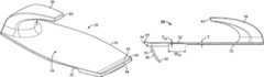
- FIG. 1is a perspective view of an embodiment of a secure hold hook.
- FIG. 1Ais a perspective view of an embodiment of a secure hold hook with a member in a partially exploded view.
- FIG. 2is a top view of the secure hold hook.
- FIG. 3is a bottom view of the secure hold hook.
- FIG. 4is a first elevation view of the secure hold hook.
- FIG. 5is a second elevation view of the secure hold hook.
- FIG. 6is a front view of the secure hold hook.
- FIG. 7is a rear view of the secure hold hook.
- FIG. 7Ais a side view of a portion of the adhesive of the secure hold hook of FIG. 1 .
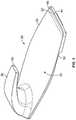
- FIG. 8is a front view of an embodiment of a secure hold hook.
- FIG. 9is a side view of the secure hold hook of FIG. 8 .
- FIG. 9Ais a side view of a portion of the adhesive of the secure hold hook of FIG. 8 .
- FIG. 10is a perspective view of an embodiment of a secure hold hook.
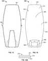
- FIG. 11is a top view of the secure hold hook.
- FIG. 12is a bottom view of the secure hold hook.
- FIG. 13is a first elevation view of the secure hold hook.
- FIG. 14is a second elevation view of the secure hold hook.
- FIG. 15is a front view of the secure hold hook.
- FIG. 16is a rear view of the secure hold hook.
- FIG. 16Ais a side view of a portion of the adhesive of the secure hold hook of FIG. 10 .
- FIGS. 1-7depict an embodiment of a secure hold hook 20 .
- the secure hold hook 20may be configured to selectively attach to an appropriate surface, including, without limitation, drywall, wood, plastic, rubber, cork, and any combination of such.
- the secure hold hook 20may be configured to be selectively removed from the appropriate surface with little to no damage resulting to the appropriate surface, as described in more detail below.
- the secure hold hook 20may be of any appropriate configuration and is not limited to that shown and described herein.
- the secure hold hook 20may include a body 24 .
- the body 24may be of any appropriate shape and size, such as by way of a non-limiting example, being generally planar.
- the body 24may be generally thin, i.e., it may have a thickness T that is between approximately 0.03 and 0.07 inches. It should be understood, however, that the body 24 may be of any appropriate thickness and is not limited to that described herein.
- the body 24may be elongated such that it may be longer than it is wide, i.e., it may extend more longitudinally than it does laterally. However, the present teachings are not limited to this configuration. By way of a non-limiting example, the body 24 may be approximately 1.25 to 4 inches in length L and may be approximately 0.5 to 1.75 inches in width W. It should be understood, however, that these dimensions are merely exemplary and the present teachings are not limited to the body 24 being of these dimensions.
- the body 24may be formed of any appropriate material, including, without limitation, plastic, metal, rubber or any combination of such. Further, the body 24 may be monolithically formed or formed through subsequent operations.
- the body 24may include a first surface 28 and a second surface 32 . At least a portion of the first surface 28 may be generally planar as shown in FIG. 6 —further, the entire first surface 28 may be generally planar. The first surface 28 may extend outward when the secure hold hook 20 is operatively secured with the appropriate surface. The first surface 28 being generally planar may permit a cover or such other decorative member 30 to be selectively attached with the secure hold hook 20 , such as shown in FIG. 1A .
- the decorative member 30may be of any appropriate configuration. By way of a non-limiting example, the decorative member 30 may be selectively attached with the first surface 28 —it may be configured to be selectively attached with a portion of the first surface 28 or the entire first surface 28 .
- the decorative member 30may be attached in any manner.
- the decorative member 30may include a removable adhesive that may selectively attach with the first surface 28 .
- the adhesivemay be of a configuration such that the user may remove the decorative member 30 and either leave the secure hold hook 20 as is or add another decorative member 30 . Further, the decorative member 30 may be selectively attached through static cling.
- the decorative member 30may include any appropriate decorative finish. For example, it may be a wood grain finish, a metal or metallic finish, a brick finish, a stone finish, any variety of color with any appropriate finishes (e.g., matte, egg shell, etc.).
- the decorative member 30may include a relatively thin membrane that includes a decorative finish on one side and either adhesive or a static cling finish to selectively and removably attach with the first surface 28 .
- the second surface 32may extend inward toward the appropriate surface when the secure hold hook 20 is operatively secured with the appropriate surface. As shown in FIG. 7 , at least a portion of the second surface 32 may be generally planar—further, the entire second surface 32 may be generally planar.
- the body 24may also include a top portion 36 and a bottom portion 40 as shown for example in FIG. 7 .
- An indicator 44may be positioned on the top portion 36 on the first surface 28 of the body 24 .
- the indicator 44may provide an indication or guide to the user as how the secure hold hook 20 may be selectively removed from the surface to which it is attached, as described in more detail below.
- the indicator 44may be of any appropriate configuration and is not limited to that shown.
- the indicator 44may include a tab 44 that extends from the top portion 36 and first surface 28 .
- the tab 44may include a grasping portion 48 that may assist the user in grasping the tab 44 such as to remove the secure hold hook 20 from the applicable surface.
- the grasping portion 48may be of any appropriate configuration.
- the grasping portion 48may include a plurality of raised ridges 50 that extend from the tab 44 , such as the two raised ridges shown in FIGS. 1 and 6 . Further, the grasping portion 48 may be depressed ridges, detents, nubs, knurled surface, or may be of any appropriate configuration such that may assist a user with grasping.
- the secure hold hook 20may include a hinge 52 that may be in any appropriate position on the body 24 .
- the hinge 52may be generally positioned between the top and bottom portions 36 , 40 of the body 24 . Further, the hinge 52 may be adjacent to or in proximity to the grasping portion 48 .
- the hinge 52may be of any appropriate configuration. As shown in FIGS. 4 and 7 , the hinge 52 may have a width W H of approximately between 0.15 and 1.75 inches, which may result in the hinge 52 being between 4% and 19% of the length L of the body 24 .
- the extra-wide hinge 52may spread the curvature of the hinge 52 over a wider area generally preventing a large bend of material. This may prevent weakening of the body 24 , and may prevent whiting that may otherwise occur with hinges. This may extend the lifecycle of the body 24 and ultimately the lifecycle of the secure hold hook 20 —and may maintain a positive aesthetic appearance.
- the hinge 52may be any appropriate configuration—the hinge 52 may be configured such that the top portion 36 of the body 24 pivots or bends relative to the bottom portion 40 of the body 24 .
- the hinge 52may be a living hinge, i.e., it may be monolithically formed with the body 24 .
- the hinge 52may have a thickness T H that is thinner than either or both of the top 36 and bottom 40 portions T of the body 24 . The thickness T H being less may form the living hinge. It should be understood, however, that the hinge 52 may be of any appropriate configuration and is not limited to that shown and described herein.
- the hinge 52may extend at least a portion of the width W of the body 24 .
- the hinge 52may extend an entirety of the width W of the body 24 . It should be understood, however, that the hinge 52 is not limited to this configuration.
- the hinge 52may extend only a portion of the width W, e.g., a majority of the width W, such as a middle portion of the width W.
- the secure hold hook 20may include a hook 56 extending from the first surface 28 on the bottom portion 40 of the body 24 .
- the hook 56may be of any appropriate configuration and is not limited to that shown and described.
- the hook 56may be monolithically formed with the body 24 or may be attached through a subsequent process, e.g., welding, adhering or fastening.
- the hook 56may extend toward the top portion 36 of the body 24 . As shown, the hook 56 may extend approximately one-third to one-half of the length of the body 24 —although the present teachings are not limited to this configuration.
- the hook 56may be configured to securely hold items on the secure hold hook 20 ; including, without limitation, pictures, decorations, décor, lights, jerseys, coats, shirts, memorabilia, and the like.
- the hook 56may be of a construction such that its width at the location from which it extends from the body 24 is substantially the majority of the width W of the body 24 . As shown in FIG. 6 , a width of the hook 56 W H1 at the location from which it extends from the body 24 may be between about 50% and 100% of the width W of the body 24 at the bottom portion 40 .
- the hook 56may get extend generally upward and away from the bottom portion 40 of the first surface 28 .
- the hook 56may get thinner as it extends upward and away from the bottom portion 40 of the first surface 28 .
- An end portion 60 of the hook 56may be a generally flat terminating end.
- the hook 56may be of a configuration such that items may be selectively and operatively engaged with the hook 56 to hold items to the surface to which the secure hold hook 20 is selectively attached—the operation is very simple and easy.
- the decorative member 30 mentioned abovemay include an aperture through which the hook 56 may pass when being selectively attached with the secure hold hook 20 .
- the decorative member 30may include a portion that may be selectively attached with the hook 56 in addition to the first surface 28 —the decorative member 30 may selectively attach with a portion of the hook 56 or the entire hook 56 .
- the hook 56may be generally hollow. This may reduce the overall weight of the secure hold hook 20 —although the present teachings are not limited to the hook 56 being generally hollow.
- the hook 56may instead by generally filled with a material of the hook 56 or the body 24 or both.
- the hook 56may have an overall thickness to handle an appropriate amount of weight of the item so attached during use.
- the secure hold hook 20may be able to withstand an appropriate amount of weight when holding the item such that the secure hold hook 20 does not remove from the appropriate surface unless and until desired by the user.
- the hook 56 being generally hollowmay result in a cavity 64 being formed in the second surface 32 of the body 24 .
- the cavity 64may extend into the hook 56 .
- a generally planar portion 68may generally circumscribe the cavity 64 as shown in FIG. 7 .
- the generally planar portion 68may provide a surface to which an adhesive may be attached with the second surface 32 of the body 24 as explained in more detail below.
- the secure hold hook 20may include an adhesive 72 of any appropriate configuration.
- the adhesive 72may be operatively attached with the second surface 32 at the bottom portion 40 of the body 24 .
- the adhesive 72may generally circumscribe the cavity 64 —the adhesive 72 may be operatively attached with the planar portion 68 of the second surface 32 .
- the adhesive 72being operatively attached with the planar portion 68 may provide a good adhesion to the body 24 . This may further provide support to the secure hold hook 20 ; especially at a location of the hook 56 operatively engaging an item.
- the planar portion 68may provide a solid surface to which the adhesive 72 may adhere. Further, the planar portion 68 may similarly provide a solid surface to engage with the surface to which the secure hold hook 20 is selectively attached.
- the adhesive 72may generally cover the entire bottom portion 40 of the second surface 32 . In these embodiments, the adhesive 72 may extend from the planar portion 68 at the bottom portion 40 to the hinge 52 . In other embodiments, the adhesive 72 may generally cover a majority of the bottom portion 40 of the second surface 32 to the hinge 52 , which may constitute any portion of the majority portion of the bottom portion 40 of the second surface 32 .
- the adhesive 72may include a first adhesive 73 that operatively attaches with the second surface 32 of the body 24 .
- This first adhesive 73may be a permanent adhesive of any appropriate configuration/formulation.
- the adhesive 72may further include a second adhesive 74 that may operatively attach with the applicable surface to which the secure hold hook 20 is attached.
- the second adhesive 74may comprise a removable adhesive of any appropriate configuration/formulation.
- the adhesive 72may include a double sided adhesive foam tape—such double-sided tapes are known to those of skill in the art and are available from Essentra Specialty Tapes of Forest Park, Ill., USA.
- the first adhesive 73may comprise an extremely aggressive permanent adhesive on one side and the second adhesive 74 may comprise a removable adhesive on the other side.
- the removable side/second adhesive 74may include a liner 75 configured to remove cleanly from the second adhesive 74 to expose the second adhesive 74 during operation of the secure hold hook 20 .
- the second adhesive 74may be configured to be cleanly removed from most hard, non-delaminating surfaces even after extended periods of time.
- the adhesive 72may include a foam core (not shown) positioned between the first and second adhesives 73 , 74 , e.g., the foam core may be sandwiched between the first and second adhesives 73 , 74 .
- the adhesive 72may include two removable adhesives 73 , 74 , which may be of similar configuration and formulation or may be of different configuration and formulation.
- the first adhesive 73may include a removable adhesive instead of the permanent adhesive described above.
- the first removable adhesive 73may have less tacky adhesive than the second removable adhesive 74 .
- the usermay remove the body 24 of the secure hold hook 20 from the first removable adhesive 73 .
- the usermay then remove the second removable adhesive 74 from the appropriate surface to which the secure hold hook 20 is selectively attached.
- the adhesive 72may include two removable adhesives 73 , 74 whereby the first adhesive 73 is tackier than the second adhesive 74 such that the user may remove the secure hold hook 20 by selectively detaching the second adhesive 74 from the appropriate surface.
- first and second adhesives 73 , 74may be configured to be cleanly removed from most hard, non-delaminating surfaces even after extended periods of time.
- the secure hold hook 20may include an engaging member 76 configured to operatively secure a surface to which the secure hold hook 20 is attached.
- the engaging member 76may provide an additional engaging feature in addition to the adhesive 72 .
- the adhesive 72 in addition to the engaging member 76may allow the secure hold hook 20 to be attached to a surface and withstand more forces than other prior art versions.
- the engaging member 76may be coupled with the body 24 in any appropriate manner.
- the engaging member 76may be operatively engaged with the top portion 36 of the body 24 .
- the engaging member 76may be operatively engaged with the second surface 32 of the body 24 at the top portion 36 in any appropriate manner such that it extends from the second surface 32 generally opposite the hook 56 .
- the engaging member 76may include a fastener, such as a nail.
- the nail 76may include a head 80 .
- the head 80may be operatively engaged with the top portion 36 of the body 24 .
- the body 24may be formed with the fastener 76 operatively secured therein, such as being co-molded therewith. This may generally prevent the fastener 76 from being removed from the body 24 . During operation, the fastener 76 may not become disengaged from the body 24 . This may make it easier for a user to manipulate the secure hold hook 20 —as the fastener 76 is not generally removable from the body 24 . In other embodiments, the fastener 76 may be removably attached with the body 24 —the fastener 76 may be operatively and removably attached in any appropriate manner. The present teachings are not limited to the configuration shown and described.
- the top portion 36may include a groove 84 into which the head 80 of the fastener 76 may be operatively engaged, i.e., it may be selectively inserted into the groove 84 .
- the engagement of the groove 84 and head 80may generally prevent the fastener 76 from inadvertently removing or otherwise falling out of engagement with the body 24 .
- the fastener 76may be replaced as necessary.
- the fastener 76may include a generally curved body 88 and a piercing end 92 , such as the generally sharpened end 92 .
- the curved body 88may allow the installation of the secure hold hook 20 easier.
- the curved body 88 of the fastener 76may rotate in a generally arcuate path. This may allow insertion of the fastener 76 into the applicable surface easier for the user.
- the piercing end 92may be of a configuration such that the user may be capable of inserting the piercing end 92 into a surface with little effort.
- the piercing end 92may be of a configuration such that as the user begins to engage the applicable surface, the piercing end 92 may pierce the applicable surface with little effort required by the user. Once the piercing end 92 has pierced the surface to which the secure hold hook 20 is being attached, the curved body 88 may continue to be inserted into the surface. Upon such insertion, in addition to the adhesive 72 being attached with the surface, the secure hold hook 20 may be operatively attached with the surface.
- the fastener 76may be small such that the hole made in the surface to which the secure hold hook 20 attaches is very small and may be imperceptive to the user upon removal of the secure hold hook 20 —which may result in the appropriate surface having little to no damage upon removal of the secure hold hook 20 .
- the usermay determine the location on the particular surface to which the user desires to attach the secure hold hook 20 . Once the user identifies the location, the user may remove the liner 75 from the second adhesive 74 , i.e., the removable adhesive. The user may adhere the secure hold hook 20 with the applicable surface by adhering the adhesive 72 to the surface. The user may then grasp the grasping portion 48 and rotate the top portion 36 relative to the bottom portion 40 toward the applicable surface. The top portion 36 may rotate at the hinge 52 . The user may continue to apply pressure until the piercing end 92 of the fastener 76 pierces the applicable surface. The user may continue to rotate the top portion 36 so that the curved body 88 may continue to be inserted into the applicable surface. The user may continue to apply force until second surface 32 of the top portion 36 engages or otherwise contacts the applicable surface—the secure hold hook 20 is operatively attached with the surface. The user may selectively secure to the hook 56 any appropriate item.
- the usermay remove the secure hold hook 20 from the surface to which it is attached by grasping the grasping portion 48 .
- the usermay pull the grasping portion 48 away from the surface and may pivot the top portion 36 downward at the hinge 52 .
- the usermay continue this motion until the fastener 76 is removed from the surface.
- the usermay continue to pull the grasping portion 48 downward.
- the second adhesive 74 attached with the wallis removable. Accordingly, as the user pulls downward, the user may overcome the force of the second adhesive 74 and the second adhesive 74 may give way allowing removal of the remaining portion of the secure hold hook 20 .
- the first adhesive 73being a permanent adhesive results in the first adhesive 73 remaining operatively engaged with the second surface 32 of the body 24 , i.e., the first adhesive 73 is configured to remain operatively engaged with the body 24 during removal of the secure hold hook 20 .
- the fastener 76may be of a configuration to leave a very small to imperceptible hole on the applicable surface and the second adhesive 74 may be removed entirely from the applicable surface and may leave the applicable surface generally undamaged.
- a secure hold hook 200is shown in FIGS. 8 and 9 .
- the secure hold hook 200may be configured to be selectively attached to an applicable surface.
- the secure hold hook 200may include a body 224 .
- the body 224may be of any appropriate shape and size and is not limited to that shown and described herein.
- the body 224may include a first surface 228 and a second surface 232 .
- the first surface 228may be generally planar as shown in FIG. 8 .
- the first surface 228may extend outward when the secure hold hook 200 is operatively secured with the applicable surface.
- the body 224may include a top portion 236 and a bottom portion 240 as shown in FIG. 9 .
- the secure hold hook 200may include a hinge 252 that may be in any appropriate position on the body 224 .
- the hinge 252may be generally positioned between the top portion 236 and bottom portion 240 of the body 224 .
- the hinge 252may be any appropriate configuration such that the top portion 236 of the body 224 may pivot or bend relative to the bottom portion 240 of the body 224 .
- the hinge 252may be a living hinge, i.e., it may be monolithically formed with the body 224 .
- the hinge 252may be thinner than either or both of the top 236 and bottom 240 portions of the body 224 .
- the secure hold hook 200may include a hook 256 attached with side portions 268 of the body 224 .
- the hook 256may be of any appropriate configuration and is not limited to that shown and described.
- the hook 256may be formed from a different material from that of the body 224 .
- the hook 256may be formed from metal, such as steel, aluminum, or the like.
- the body 224may be formed from a plastic or rubber material, such as polypropylene, polyethylene, and the like.
- the hook 256may extend downward from the body 224 and may include a portion 260 that extends back toward the top portion 236 of the body 224 . As shown, the hook 256 may be able to pivot with respect to the body 224 .
- the hook 256may be pivotally attached with the body 224 in any appropriate manner.
- end portions 264 of the hook 256may be inserted into the side portions 268 of the body 224 such that the hook 256 is capable of pivoting with respect to the body 224 .
- the hook 256 and body 224may be formed of substantially the same material.
- the secure hold hook 200may include an adhesive 272 of any appropriate configuration, such as that described above.
- the adhesive 272may be operatively attached with the second surface 232 at the bottom portion 240 of the body 224 .
- the bottom portion 240may be generally planar, which may provide a solid surface to which the adhesive 272 may adhere.
- the adhesive 272may generally cover the entire bottom portion 240 of the second surface 232 . In these embodiments, the adhesive 272 may extend from the bottom portion 240 to the hinge 252 . In other embodiments, the adhesive 272 may generally cover a majority of the bottom portion 240 of the second surface 232 to the hinge 252 —which may include any majority portion of the bottom portion 240 .
- the adhesive 272may include a first adhesive 273 that operatively attaches with the second surface 232 of the body 224 .
- This first adhesive 273may be a permanent adhesive or may be a removable adhesive of any appropriate configuration/formulation, such as detailed above.
- the adhesive 272may include a second adhesive 274 that may operatively attach with the applicable surface to which the secure hold hook 200 is attached.
- the second adhesive 274may comprise a removable adhesive of any appropriate configuration/formulation.
- the adhesive 272may include a foam core 276 that may be generally positioned between the first and second adhesives 273 , 274 .
- the foam core 276may be of any appropriate configuration and may be of any appropriate thickness. As shown in FIG.
- the foam core 276may be sandwiched between the first and second adhesives 273 , 274 .
- the first and second adhesives 273 and 274 along with the foam core 276may be of any appropriate thickness, which may be of different thicknesses.
- the adhesive 272may include a double sided adhesive foam tape, which includes the first and second adhesive 273 , 274 and the foam core 276 .
- the first adhesive 273may be a removable adhesive whereby the user may pull the body 224 from the first adhesive 273 . In such embodiments, the user may then remove the adhesive 272 by overcoming the adhesive force of the second adhesive 274 from the applicable surface.
- a liner 275may be removably attached with the second adhesive 274 to cover or otherwise protect the second adhesive 274 during non-use of the secure hold hook 200 .
- the liner 275may be of a configuration such that a user may pull or otherwise disengage the liner 275 from the second adhesive 274 during use.
- the liner 275may be of any appropriate material.
- the second adhesive 274may be configured to be cleanly removed from most hard, non-delaminating surfaces even after extended periods of time and in those embodiments in which the first adhesive 373 is a removable adhesive, it may be configured to be cleanly removed from most hard, non-delaminating surfaces even after extended periods of time.
- the secure hold hook 200may include an engaging member 276 configured to operatively secure a surface to which the secure hold hook 200 is attached.
- the engaging member 276may provide an additional engaging feature in addition to the adhesive 272 .
- the adhesive 272 in addition to the engaging member 276may allow the secure hold hook 200 to be attached to a surface and withstand more forces than other prior art versions.
- the engaging member 276may be coupled with the body 224 in any appropriate manner.
- the engaging member 276may be operatively engaged with the top portion 236 and second surface 242 of the body 224 in any appropriate manner.
- the engaging member 276may include a fastener, such as a nail. A portion of the nail 276 may be inserted into the top portion 236 of the body 224 .
- the nail 276may include a generally curved body 288 and a piercing end 292 , such as the generally sharpened end 292 .
- the curved body 288may allow the installation of the secure hold hook 200 easier.
- the curved body 288 of the fastener 276may rotate in a generally arcuate path. This may allow insertion of the nail 276 into the applicable surface easier for the user.
- the piercing end 292may be of a configuration such that the user may be capable of inserting the piercing end 292 into a surface with little effort. Once the piercing end 292 has pierced the surface to which the secure hold hook 200 is being attached, the curved body 288 may continue to be inserted into the surface. Upon such insertion, in addition to the adhesive 272 being attached with the surface, the secure hold hook 200 may be operatively attached with the surface.
- a secure hold hook 300may be configured to be selectively attached to an applicable surface.
- the secure hold hook 300may include a body 324 .
- the body 324may be of any appropriate shape and size, such as by way of a non-limiting example, being generally planar.
- the body 324may be generally thin, i.e., it may have a thickness T 1 that is between approximately 0.03 and 0.07 inches. It should be understood, however, that the body 324 may be of any appropriate thickness and is not limited to that described herein.
- the body 324may be elongated such that it may be longer than it is wide, i.e., it may extend more longitudinally than it does laterally. However, the present teachings are not limited to this configuration. By way of a non-limiting example, the body 324 may be approximately 1.25 to 4 inches in length L 1 and may be approximately 0.5 to 1.75 inches in width W 1 . It should be understood, however, that these dimensions are merely exemplary and the present teachings are not limited to the body 324 being of these dimensions.
- the body 324may include a first surface 328 and a second surface 332 .
- the first surface 328may be generally planar as shown in FIG. 16 .
- the first surface 328may extend outward when the secure hold hook 300 is operatively secured with the applicable surface.
- the second surface 332may extend inward toward the applicable surface with the secure hold hook 300 is operatively secured with the applicable surface.
- the secure hold hook 300may include a hook 356 extending from the first surface 328 of the body 324 .
- the hook 356may be of any appropriate configuration and is not limited to that shown and described.
- the hook 356may be monolithically formed with the body 324 or may be attached through a subsequent process, e.g., welding, adhering or fastening.
- the hook 356may extend toward a top portion 361 of the body 324 . As shown, the hook 356 may extend approximately one-third to one-half of the length of the body 324 .
- the hook 356may be of a configuration to hold items on the secure hold hook 300 .
- the hook 356may be of a construction such that its width at the location from which it extends from the body 324 is substantially the majority of the width of the body 324 . As shown, the width of the hook 356 at the location from which it extends from the body 324 may be between about 50% and 100% of the width of the body 324 .
- the hook 356may get extend generally upward and away from the first surface 328 .
- the hook 356may get thinner as it extends upward and away from the first surface 328 .
- An end portion 360 of the hook 356may be generally flat terminating end.
- the hook 356may be generally hollow. This may reduce the overall weight of the secure hold hook 300 .
- the hook 356may be of an overall thickness to handle an appropriate amount of weight of the item so attached during use to remain in an operative position on the applicable surface. Further, the hook 356 may not be hollow, but may include material of either or both of the body 324 and hook 356 .
- the hook 356 being generally hollowmay result in a cavity 364 being formed in the second surface 332 of the body 324 —the cavity 364 may reduce the overall weight of the secure hold hook 300 while generally maintaining its strength.
- the cavity 364may extend into the hook 356 .
- a generally planar portion 368may generally circumscribe the cavity 364 as shown in FIG. 16 .
- the generally planar portion 368may provide a surface to which an adhesive may be attached with the second surface 332 of the body 324 as explained in more detail below.
- the secure hold hook 300may include an adhesive 372 of any appropriate configuration.
- the adhesive 372may be operatively attached with the second surface 332 of the body 324 .
- the adhesive 372may generally circumscribe the cavity 364 —the adhesive 372 may be operatively attached with the planar portion 368 of the second surface 332 .
- the adhesive 372 being operatively attached with the planar portion 368may provide a good adhesion to the body 324 . This may further provide support to the secure hold hook 300 .
- the planar portion 368may provide a solid surface to which the adhesive 372 may adhere. Further, the planar portion 368 may similarly provide a solid surface to engage with the applicable surface to which the secure hold hook 300 is selectively attached.
- the adhesive 372may generally cover the entire second surface 332 . In these embodiments, the adhesive 372 may extend around the planar portion 368 and upwards covering the remaining portion of the second surface 332 . In other embodiments, the adhesive 372 may generally cover a majority of the second surface 332 —in such embodiments, the adhesive 372 may cover any majority portion of the second surface 332 .
- the adhesive 372may include a first adhesive 373 that operatively attaches with the second surface 332 of the body 324 .
- This first adhesive 373may be a permanent adhesive or may be a removable adhesive of any appropriate configuration/formulation.
- the adhesive 372may also include a second adhesive 374 that may operatively attach with the applicable surface to which the secure hold hook 300 is selectively attached.
- the second adhesive 374may include a removable adhesive of any appropriate configuration/formulation.
- the adhesive 372may include a foam core (not shown) positioned between the first and second adhesives 373 , 374 .
- the adhesive 372may include a double sided adhesive foam tape.
- the first adhesive 373may comprise an extremely aggressive permanent adhesive on one side and the second adhesive 374 may comprise a removable adhesive on the other side.
- the present teachingsare not limited to this configuration.
- the first adhesive 373may be a removable adhesive whereby the user may pull the body 324 from the first adhesive 373 . In such embodiments, the user may then remove the adhesive 372 by overcoming the adhesive force of the second adhesive 374 from the applicable surface.
- the removable side/second adhesive 374may include a liner 375 configured to remove cleanly to expose the second adhesive 374 during attaching of the secure hold hook 300 to the applicable surface.
- the second adhesive 374may be configured to be cleanly removed from most hard, non-delaminating surfaces even after extended periods of time—in those embodiments in which the first adhesive 373 is a removable adhesive, it may be configured to be cleanly removed from most hard, non-delaminating surfaces even after extended periods of time.
- a liner 375may be attached with the second adhesive 374 , the liner 375 generally preventing exposure of the second adhesive 374 .
- the usermay select a location on the applicable surface to which the secure hold hook 300 is to be secured.
- the usermay remove the liner 375 from the second surface 374 .
- the usermay align the secure hold hook 300 in an operative position and adhere the secure hold hook 300 to the applicable surface.
- the usermay grasp the secure hold hook 300 at or near the top portion thereof 361 . The user may then pull downward on the secure hold hook 300 . The user may need only to apply enough force to overcome the adhesion between the second adhesive 374 and the surface. In such embodiments, the permanent or first adhesive 373 may be stronger, which may generally prevent the permanent or first adhesive 373 from becoming disengaged from the second surface 332 of the body 324 . Once the user has overcome the adhesion between the removable adhesive 373 and the surface, the user may remove the secure hold hook 300 from the surface.
- the adhesive 372may be of a configuration that no damage occurs to the surface from which the secure hold hook 300 is removed.
Landscapes
- Supports Or Holders For Household Use (AREA)
- Engineering & Computer Science (AREA)
- General Engineering & Computer Science (AREA)
- Mechanical Engineering (AREA)
Abstract
Description
Claims (18)
Priority Applications (2)
| Application Number | Priority Date | Filing Date | Title |
|---|---|---|---|
| US14/160,835US10925417B2 (en) | 2014-01-22 | 2014-01-22 | Secure hold hook |
| US17/153,995US20210137290A1 (en) | 2014-01-22 | 2021-01-21 | Secure hold hook |
Applications Claiming Priority (1)
| Application Number | Priority Date | Filing Date | Title |
|---|---|---|---|
| US14/160,835US10925417B2 (en) | 2014-01-22 | 2014-01-22 | Secure hold hook |
Related Child Applications (1)
| Application Number | Title | Priority Date | Filing Date |
|---|---|---|---|
| US17/153,995ContinuationUS20210137290A1 (en) | 2014-01-22 | 2021-01-21 | Secure hold hook |
Publications (2)
| Publication Number | Publication Date |
|---|---|
| US20150201764A1 US20150201764A1 (en) | 2015-07-23 |
| US10925417B2true US10925417B2 (en) | 2021-02-23 |
Family
ID=53543729
Family Applications (2)
| Application Number | Title | Priority Date | Filing Date |
|---|---|---|---|
| US14/160,835Expired - Fee RelatedUS10925417B2 (en) | 2014-01-22 | 2014-01-22 | Secure hold hook |
| US17/153,995AbandonedUS20210137290A1 (en) | 2014-01-22 | 2021-01-21 | Secure hold hook |
Family Applications After (1)
| Application Number | Title | Priority Date | Filing Date |
|---|---|---|---|
| US17/153,995AbandonedUS20210137290A1 (en) | 2014-01-22 | 2021-01-21 | Secure hold hook |
Country Status (1)
| Country | Link |
|---|---|
| US (2) | US10925417B2 (en) |
Cited By (4)
| Publication number | Priority date | Publication date | Assignee | Title |
|---|---|---|---|---|
| USD927866S1 (en)* | 2019-10-23 | 2021-08-17 | Grohe Ag | Robe hook |
| US11116334B2 (en)* | 2019-01-24 | 2021-09-14 | Schwaab, Inc. | Mounting bracket for wall mounted items |
| USD950557S1 (en)* | 2018-06-01 | 2022-05-03 | Compal Electronics, Inc. | Keystroke mechanism for clickpad |
| US20230048965A1 (en)* | 2021-08-16 | 2023-02-16 | Ahmad Ozeir | Magnetically Attracted Plant Containers |
Families Citing this family (4)
| Publication number | Priority date | Publication date | Assignee | Title |
|---|---|---|---|---|
| CN104921574A (en)* | 2014-03-21 | 2015-09-23 | 蓝永辉 | Adhesive wall support structure |
| CA2930808A1 (en)* | 2014-06-17 | 2015-12-23 | 3M Innovative Properties Company | Article support using peel release adhesives |
| EP3796815B1 (en)* | 2018-05-23 | 2024-08-14 | 3M Innovative Properties Company | Wall anchor kit |
| USD925341S1 (en)* | 2020-01-09 | 2021-07-20 | Tesa Se | Hook for hanging |
Citations (195)
| Publication number | Priority date | Publication date | Assignee | Title |
|---|---|---|---|---|
| US2751807A (en) | 1951-12-13 | 1956-06-26 | Harre Kurt Johan Stausgaard | Thumb tack having curved shank and bent sheet metal head |
| US2765998A (en)* | 1950-06-14 | 1956-10-09 | Poster Products Inc | Supporting device |
| US3311339A (en)* | 1966-02-07 | 1967-03-28 | Bruce J Frye | Self-holding device |
| US3409257A (en)* | 1967-03-10 | 1968-11-05 | Minnesota Mining & Mfg | Cable clip with pressure sensitive attaching means |
| US3885723A (en)* | 1974-01-14 | 1975-05-27 | Robert L Magnie | Carrier device for hanger supported garments |
| US4026510A (en)* | 1976-05-17 | 1977-05-31 | Holmes Warren B | Wall hanger |
| US4300692A (en)* | 1978-07-14 | 1981-11-17 | Modiani & Associati | Latching hook structure for supporting vendible articles, particularly trinkets and the like |
| US4317554A (en)* | 1980-03-10 | 1982-03-02 | Novelty Manufacturing Company | Wreath hanger |
| US4457053A (en)* | 1982-08-17 | 1984-07-03 | Katsumi Niwa | Cable clamp |
| US4671480A (en) | 1985-06-11 | 1987-06-09 | Frye Bruce J | Demountable holding device |
| DE9108687U1 (en)* | 1991-07-15 | 1991-09-19 | De-Plastik GmbH, 7742 St. Georgen | Adhesive hooks |
| US5121896A (en)* | 1991-01-25 | 1992-06-16 | Frye Bruce J | Self securing device |
| WO1993001742A1 (en) | 1990-07-23 | 1993-02-04 | Kevin Richard Prince | Bracket for wall mounting a compact disk case |
| USD339058S (en) | 1991-06-05 | 1993-09-07 | Hook | |
| US5255800A (en) | 1992-07-30 | 1993-10-26 | Kelly Keith N | Spare tissue holder assembly |
| US5259519A (en) | 1993-01-11 | 1993-11-09 | Lieberman William B | Advertiser and hygienic disposable toothbrush holder |
| WO1994021157A1 (en) | 1993-03-23 | 1994-09-29 | Minnesota Mining And Manufacturing Company | Article support using stretch releasing adhesives |
| US5399409A (en) | 1992-07-16 | 1995-03-21 | Whiteman; Gaylen L. | Tacking device for attaching to textured surfaces |
| WO1995009548A1 (en) | 1993-10-01 | 1995-04-13 | Selfix, Inc. | Encapsulated adhesive system for a load-bearing support device |
| US5409189A (en) | 1992-09-30 | 1995-04-25 | Beiersdorf Ag | Redetachable, self-adhesive hook |
| US5433152A (en) | 1993-11-09 | 1995-07-18 | Henry; William R. | Shelf supported on a towel bar |
| US5433804A (en) | 1990-08-06 | 1995-07-18 | Nottingham Spirk Design Associates | Hot melt adhesive heating by means of microwave |
| US5433413A (en) | 1989-10-25 | 1995-07-18 | Adams Mfg. Corp. | Transparent wall hook |
| US5462782A (en) | 1993-01-22 | 1995-10-31 | Su; Ching-Fang | Adhesive plate assembly for sheet object |
| US5482242A (en) | 1994-04-11 | 1996-01-09 | Jegelius; Lennart | Suspension device for low weight articles |
| US5484066A (en) | 1992-06-22 | 1996-01-16 | Luisi; Thomas J. | Mountable object holder |
| US5494250A (en) | 1994-07-29 | 1996-02-27 | Chen; Wen-Yen | Cleaning tissue holder |
| US5507464A (en) | 1994-03-22 | 1996-04-16 | Minnesota Mining And Manufacturing Company | Article support using stretch releasing adhesives |
| US5553719A (en) | 1994-12-16 | 1996-09-10 | Campbell; Rosita | Flexible hat storage device |
| US5593120A (en) | 1994-11-21 | 1997-01-14 | Minnesota Mining And Manufacturing Company | Quick-mounting fastening assembly |
| US5718402A (en) | 1994-12-23 | 1998-02-17 | Rose Displays Ltd. | Poster gripping extrusion |
| US5738325A (en)* | 1995-01-24 | 1998-04-14 | Williams Industries, Inc. | Computer mouse pad apparatus |
| EP0838182A2 (en) | 1996-10-05 | 1998-04-29 | Beiersdorf Aktiengesellschaft | Removable adhesive hook |
| US5848772A (en) | 1996-01-02 | 1998-12-15 | Fitzgerald; Theodore L. | Kitchen cutting board storage apparatus |
| US5909758A (en) | 1995-11-27 | 1999-06-08 | Kitamura; Akio | Supporting tool and method of installing same |
| US5964437A (en) | 1997-10-27 | 1999-10-12 | Belokin; Paul | Mounting support |
| US5967474A (en) | 1997-03-01 | 1999-10-19 | Beiersdorf Ag | Holding device |
| US5979675A (en)* | 1995-12-29 | 1999-11-09 | Rainin Instrument Co., Inc. | Hanger for supporting a plurality of pipettes adjacent a horizontal support surface |
| US5984247A (en) | 1996-09-13 | 1999-11-16 | Beiersdorf Ag | Redetachable, self-adhesive device with gripping aid |
| US5989708A (en)* | 1990-12-20 | 1999-11-23 | 3M Innovative Properties Company | Removable adhesive tape |
| USD417385S (en) | 1998-08-14 | 1999-12-07 | Minnesota Mining And Manufacturing Company | Wall hook |
| US6001471A (en) | 1995-08-11 | 1999-12-14 | 3M Innovative Properties Company | Removable adhesive tape with controlled sequential release |
| US6070536A (en) | 1998-04-17 | 2000-06-06 | Cinkaj; Chris | Decorative shelving and method of making same |
| WO2000033708A1 (en) | 1998-12-04 | 2000-06-15 | Jae Kook Yang | Wall hanger hook and method for manufacturing the same |
| US6082686A (en) | 1997-08-14 | 2000-07-04 | Beiersdorf Ag | Holding device |
| US6095465A (en) | 1998-10-02 | 2000-08-01 | Weck; David | Structure for and method of mounting an object on a vertical surface and a laminated backing for such a structure |
| US6106937A (en) | 1998-06-05 | 2000-08-22 | 3M Innovative Properties Company | Stretch release adhesive article with enhanced removal feature |
| US6120867A (en) | 1998-01-27 | 2000-09-19 | 3M Innovative Properties Company | Removable tape laminate |
| US6131864A (en) | 1997-08-14 | 2000-10-17 | Beiersdorf Ag | Holding device |
| US6162534A (en)* | 1998-08-31 | 2000-12-19 | 3M Innovative Properties Company | Stretch release adhesive article with secondary release member |
| US6187404B1 (en) | 1997-08-14 | 2001-02-13 | Beiersdorf Ag | Holding device |
| WO2001034001A1 (en) | 1999-11-08 | 2001-05-17 | Mexem Pty Limited | Wall hanging device |
| US20010028022A1 (en) | 1996-04-15 | 2001-10-11 | Hamerski Michael D. | Article support using stretch releasing adhesives |
| US6325342B1 (en) | 1999-03-22 | 2001-12-04 | Jean-Francois Dignat | Ergonomic typist vertebral support |
| US20020017359A1 (en) | 1995-03-28 | 2002-02-14 | Bernd Luhmann | Use of a piece of adhesive film for a bond which can be separated without damage and without leaving a residue |
| US20020036253A1 (en) | 2000-08-02 | 2002-03-28 | Lake Gary F. | Mountable holder for writing implements |
| WO2002033274A1 (en) | 2000-09-13 | 2002-04-25 | Lan Yung Huei | An adhesive sheet type holding device for mounting onto a wall |
| US6403206B1 (en) | 1994-08-31 | 2002-06-11 | Minnesota Mining And Manufacturing Company | Removable foam adhesive tape |
| US6406781B1 (en) | 1998-06-23 | 2002-06-18 | 3M Innovative Properties Company | Stretch release adhesive article with stabilizer |
| US20020081409A1 (en) | 2000-12-22 | 2002-06-27 | Andy Shaffer | Device and a method for hanging an object as well as an object incorporating such a hanging device |
| US6431508B1 (en) | 2000-11-06 | 2002-08-13 | The United States Of America As Represented By The Secretary Of The Navy | Adaptable and universal system for attachments |
| US20020121581A1 (en) | 2001-02-14 | 2002-09-05 | Achim Franck | At least two-part hook |
| US6447196B1 (en)* | 1993-05-12 | 2002-09-10 | George A. Arkwright | Adhesive fastener assembly |
| US6458454B1 (en) | 1996-10-07 | 2002-10-01 | 3M Innovative Properties Company | Holding device |
| DE10213924A1 (en)* | 2002-03-28 | 2002-10-10 | Ver Zur Unterstuetzung Russisc | Adhering an object, eg a hook, to a surface, eg a wall, comprises applying an adhesive layer to the object and the wall, and contacting them by pressing together |
| US6467742B1 (en) | 2000-04-29 | 2002-10-22 | Rose Displays | Poster-gripping extrusion |
| US20020166874A1 (en) | 2001-05-11 | 2002-11-14 | Devaux Robert B. | Dental center |
| US20030033771A1 (en) | 2001-08-17 | 2003-02-20 | C. Anderson | House trim corner pieces and method of assembly |
| US20030034315A1 (en) | 2001-07-31 | 2003-02-20 | Amad Tayebi | Toothbrush holder and a method for assuring the hygiene of a toothbrush holder and for adapting a toothbrush holder to provide assurance of its hygiene |
| US20030047654A1 (en) | 2001-09-13 | 2003-03-13 | 3M Innovative Properties Company | Stretch releasing adhesive tape article with flexible cover |
| US6572063B1 (en) | 2001-12-13 | 2003-06-03 | Floss Today Corporation | Bracket for dental floss container |
| US20030121871A1 (en) | 2001-12-31 | 2003-07-03 | Zlatko Zadro | Height adjustable shower caddy interchangeably mountable to different structures |
| WO2003070068A1 (en) | 2002-02-23 | 2003-08-28 | Tesa Ag | Innovative hook system |
| US6616790B2 (en) | 1996-09-13 | 2003-09-09 | Tesa Ag | Redetachable, self-adhesive device |
| USD480292S1 (en)* | 2003-02-26 | 2003-10-07 | 3M Innovative Properties Company | Hook |
| US20030211317A1 (en) | 2000-07-06 | 2003-11-13 | 3M Innovative Properties Company | Stretch releasing pressure sensitive adhesive tape and articles |
| US20040016665A1 (en) | 2002-07-25 | 2004-01-29 | Kellaway Pamela A. | Portable toothbrush storage device |
| US20040020883A1 (en) | 2002-08-02 | 2004-02-05 | Brokaw Paul E. | Adhesive mounted storage rack, method, and kit |
| WO2004024467A2 (en) | 2002-09-11 | 2004-03-25 | Loctite (R & D) Limited | Surface-mounting system |
| US6722501B2 (en) | 2002-02-26 | 2004-04-20 | 3M Innovative Properties Company | Package assemblies with attachment strips |
| US20040084597A1 (en) | 2000-11-06 | 2004-05-06 | 3M Innovative Properties Company | Hanger |
| US20040098875A1 (en) | 2002-11-27 | 2004-05-27 | George Gould | Picture placement apparatus |
| US20040123503A1 (en) | 2002-12-31 | 2004-07-01 | 3M Innovative Properties Company | Graphic display device mountable with stretch releasing adhesive |
| US20040131815A1 (en) | 2003-01-06 | 2004-07-08 | Roberta Maggio | Mounting assembly for attaching articles to surfaces |
| USD494452S1 (en)* | 2002-07-08 | 2004-08-17 | Fellowes, Inc. | Hook |
| US20040188580A1 (en) | 2001-07-19 | 2004-09-30 | Hideki Ryu | Article support device |
| US20040206867A1 (en) | 2003-04-19 | 2004-10-21 | Eli Zhadanov | Device for supporting bathroom accessories and the like |
| US6808149B1 (en) | 2004-02-07 | 2004-10-26 | Merav Sendowski | Hands-free wall mounted bottle holder |
| US6835452B1 (en) | 2000-06-02 | 2004-12-28 | 3M Innovative Properties Company | Adhesive article with progressive adhesive properties and method of using same |
| US20050056756A1 (en) | 2003-09-16 | 2005-03-17 | Yu-Tzu Wang | Lock clamp apparatus |
| WO2005052388A1 (en) | 2003-11-27 | 2005-06-09 | Fernando Daniel Tega | Multiple purpose support device |
| US20050139739A1 (en)* | 2003-12-31 | 2005-06-30 | Hamerski Michael D. | Magnetic-adhesive mounting device |
| US20050163959A1 (en) | 2003-12-22 | 2005-07-28 | Crant Corporation | Wall covering system and mounting member therefor |
| US20050210695A1 (en) | 2004-03-05 | 2005-09-29 | Omnimount Systems, Inc. | Methods and apparatuses for mounting a flat panel video display |
| US20050247841A1 (en) | 2004-05-07 | 2005-11-10 | Jeffrey S. Brooks, Inc. | Funnel-shaped holder with mount for attaching to surface |
| US6976595B1 (en) | 2003-06-11 | 2005-12-20 | Marilyn Geller | Retractable system for hanging storage |
| US20060021272A1 (en) | 2004-08-02 | 2006-02-02 | 3M Innovative Properties Company | Device for supporting a substantially planar article |
| US20060054771A1 (en) | 2004-09-13 | 2006-03-16 | Lie Chien C | Level hanger device for pictures or the like |
| US20060068144A1 (en) | 2004-09-29 | 2006-03-30 | 3M Innovative Properties Company | Stretch releasing adhesive article for fragile surfaces |
| US20060124811A1 (en) | 2004-12-14 | 2006-06-15 | Tatarsky Gil R | Universal hook systems |
| US20060156679A1 (en) | 2005-01-14 | 2006-07-20 | Pierret Dennis M | Crown molding and deck material attachments |
| WO2006097282A1 (en) | 2005-03-15 | 2006-09-21 | Henkel Kommanditgesellschaft Auf Aktien | Adhesive tape comprising a multi-layer structure |
| WO2006097042A1 (en) | 2005-03-16 | 2006-09-21 | Yung-Hui Lan | Adhesive film type support member for wall surface |
| USD530192S1 (en)* | 2005-12-21 | 2006-10-17 | Magdalena Becerra | Adhesive backed clip |
| US20060243880A1 (en) | 2005-05-02 | 2006-11-02 | Terry Lane | Bracket assembly to suspend objects |
| WO2007013067A2 (en) | 2005-07-25 | 2007-02-01 | M.G.H. Agricultural Cooperative Society Ltd. | Drywall hanging devices and corresponding methods |
| US20070029355A1 (en) | 2005-03-07 | 2007-02-08 | Dente Gerald A Jr | Wall & rod multiple garment hanger |
| WO2007016733A1 (en) | 2005-08-08 | 2007-02-15 | International Consolidated Business Pty. Ltd. | A spray cap with a hook projecting outside the skirt of the cap through a slot |
| US20070096003A1 (en)* | 2005-11-03 | 2007-05-03 | Kuo Liao Hsiu-Mei | Sticker type wall surface holder |
| US20070102601A1 (en) | 2005-11-10 | 2007-05-10 | 3M Innovative Properties Company | Mounting device |
| US7216841B2 (en) | 2002-11-01 | 2007-05-15 | Dodig Jr John M | Method and apparatus for hanging pictures and other wall objects |
| USD543837S1 (en) | 2005-06-21 | 2007-06-05 | 3M Innovative Properties Company | Hook design |
| WO2007075771A1 (en) | 2005-12-21 | 2007-07-05 | 3M Innovative Properties Company | Peelable adhesive tape and article-attaching kit |
| US20070207311A1 (en) | 2004-11-12 | 2007-09-06 | Henkel Kommanditgesellschaft Auf Aktien (Henkel Kgaa) | Double-Sided Adhesive Strip with a Higher Bearing Force |
| WO2007123784A2 (en) | 2006-04-04 | 2007-11-01 | Rc Group, Inc. | Hanger & method of use |
| USD554481S1 (en) | 2006-07-14 | 2007-11-06 | 3M Innovative Properties Company | Adhesively mountable hook |
| USD554483S1 (en)* | 2006-12-01 | 2007-11-06 | 3M Innovative Properties Company | Hook |
| US20070257165A1 (en) | 2005-06-21 | 2007-11-08 | Peter Newbould | Article support device mountable with stretch releasing adhesive |
| WO2007144726A1 (en) | 2006-06-13 | 2007-12-21 | Clifton Aubrey Van Der Hoven | Adhesive mounting products and articles provided with mounting adhesive |
| US20070295436A1 (en) | 2006-06-26 | 2007-12-27 | Mark Joseph | Pressure application system for adhesive mounted articles |
| US20070295879A1 (en) | 2006-06-27 | 2007-12-27 | Hammond Wong | Picture frame positioner |
| US20080035818A1 (en) | 2006-07-24 | 2008-02-14 | We-Flex, Llc | Portable item holder and method for using the holder |
| US20080053934A1 (en) | 2006-09-06 | 2008-03-06 | 3M Innovative Properties Company | Adhesively mountable angled wall shelf |
| US20080053345A1 (en) | 2006-09-06 | 2008-03-06 | 3M Innovative Properties Company | Wall mountable shelving system with rectangular frame and removable trays |
| US20080053931A1 (en) | 2006-09-06 | 2008-03-06 | 3M Innovative Properties Company | Horizontally mounted shelf assembly and accessories therefor |
| WO2008030816A1 (en) | 2006-09-06 | 2008-03-13 | 3M Innovative Properties Company | Wall mountable wire grid organizer system with removable accessories |
| USD572121S1 (en) | 2007-12-12 | 2008-07-01 | Shiffler Equipment Sales, Inc. | Combination coat and backpack hook |
| WO2008122902A2 (en) | 2007-04-06 | 2008-10-16 | Artech Srl | Element for fixing items to a wall, and method for fixing said element to a wall. |
| US7448582B2 (en) | 2003-01-16 | 2008-11-11 | Jeffrey Jackson | Apparatus for displaying more than one object |
| US20080296244A1 (en) | 2007-05-30 | 2008-12-04 | Tomassetti Louis D | Wall hook for safety razors |
| US7464907B1 (en) | 2007-10-09 | 2008-12-16 | Terry Lane | Bracket assembly to suspend objects |
| USD584939S1 (en) | 2006-08-14 | 2009-01-20 | Interdesign, Inc. | Over cabinet single hook |
| US20090039225A1 (en) | 2005-09-07 | 2009-02-12 | Michael Taylor | Surfcraft Holder |
| US20090200253A1 (en) | 2008-02-13 | 2009-08-13 | Sandow Adam I | Interchangeable retail store display |
| US20090205784A1 (en) | 2006-02-01 | 2009-08-20 | Sudo Yasuo | Article support structure and article attachment kit |
| US20090242712A1 (en) | 2008-03-27 | 2009-10-01 | 3M Innovative Properties Company | Surface mount systems and methods |
| USD603688S1 (en) | 2008-12-02 | 2009-11-10 | Caimon Enterprise Co., Ltd. | Panel wall hook |
| US20100018082A1 (en)* | 2008-07-26 | 2010-01-28 | Dawn Stokes | Double-sided adhesive retainer for footwear |
| USD609995S1 (en)* | 2008-06-16 | 2010-02-16 | 3M Innovative Properties Company | Hook |
| US20100050398A1 (en) | 2008-09-03 | 2010-03-04 | Brian Edward Gokey | Invisible magnetic quilt hanger |
| WO2010040425A1 (en) | 2008-10-11 | 2010-04-15 | Harald Stallegger | Universal hook |
| US20100102182A1 (en) | 2008-10-29 | 2010-04-29 | Pi-Fen Lin | Portable electronic device and magnetic fixation board therefor |
| US20100155565A1 (en) | 2008-12-18 | 2010-06-24 | Jay Alan Bernstein | Method and apparatus for affixing objects to a wall |
| US7807007B2 (en)* | 2005-03-23 | 2010-10-05 | Velcro Industries B.V. | Molding touch fastener elements |
| US20100314511A1 (en) | 2009-06-12 | 2010-12-16 | Physical Systems, Inc. | Low profile adhesive mounted fixture button |
| WO2011000469A1 (en) | 2009-07-02 | 2011-01-06 | Inge Lidl | Adhesive support and method for fastening said adhesive support |
| US20110024585A1 (en) | 2009-07-30 | 2011-02-03 | Andrew Dale Brinkdopke | Mounting Bracket and Wall Mountable Material Dispensing System |
| US20110031198A1 (en) | 2009-08-05 | 2011-02-10 | Trettin David J | Adjustable curtain rod |
| US20110056896A1 (en) | 2009-09-07 | 2011-03-10 | Tzekova Bistra M | Towel holder |
| US20110089226A1 (en) | 2007-05-17 | 2011-04-21 | Morrison David J | Photo display hanger and kit |
| US20110101188A1 (en) | 2009-10-29 | 2011-05-05 | Groepler Elizabeth A | Method for hanging party favors and apparatus and kits apparatus related thereto |
| WO2011062998A2 (en) | 2009-11-18 | 2011-05-26 | Battelle Memorial Institute | Anodes for lithium ion batteries |
| US20110146126A1 (en) | 2009-12-22 | 2011-06-23 | Charles Phillips | Device for and method of holding and displaying sheet articles |
| US20110174940A1 (en) | 2010-01-21 | 2011-07-21 | Edward Cai | Hook for hanging object on a wall |
| US20110220295A1 (en) | 2006-08-18 | 2011-09-15 | Tesa Se | Pressure-sensitive adhesive strip for moisture-insensitive peelable adhesive bonds |
| US20110290965A1 (en) | 2010-05-28 | 2011-12-01 | William Kyle Virgin | Mounting system for removably securing an object to a surface |
| US8087180B1 (en) | 2010-10-02 | 2012-01-03 | David Clayton | Adjustable picture frame wall hanging template system |
| US20120009548A1 (en)* | 2010-07-10 | 2012-01-12 | Melissa Dawn Feit | Swatch Organizer System and Method of Creating and Mounting Swatches |
| WO2012017292A1 (en) | 2010-08-05 | 2012-02-09 | Tecnoform S.P.A. | Supporting wall |
| US20120032043A1 (en) | 2010-08-04 | 2012-02-09 | 3M Innovative Properties Company | Adhesively mounted article support assembly with exposed pull tab |
| US20120056051A1 (en) | 2010-09-03 | 2012-03-08 | Peter Gold | Fastener assembly |
| US20120112022A1 (en) | 2010-08-11 | 2012-05-10 | Cheng-Ge Cheng | Wall mount hanger |
| US20120132602A1 (en) | 2010-06-01 | 2012-05-31 | Millspaugh David A | Shelf unit |
| WO2012078085A1 (en) | 2010-12-10 | 2012-06-14 | Sca Hygiene Products Ab | A support device |
| US20120145847A1 (en) | 2009-09-11 | 2012-06-14 | Dong Guan Ren-River Rubber Products Co., Ltd. | Hook |
| US20120153102A1 (en) | 2010-12-20 | 2012-06-21 | 3M Innovative Properties Company | Article support device comprising a rotatable connection |
| WO2012084476A1 (en) | 2010-12-24 | 2012-06-28 | Ortwein Friederike | Fastener |
| US20120164914A1 (en) | 2010-08-27 | 2012-06-28 | O'connor Stacy Lynn | Wall mounted toy track set |
| US20120183714A1 (en) | 2011-01-17 | 2012-07-19 | Catherine Hsui-Feng Peng | Multi-function reusable sticker teaching tool |
| US20120187270A1 (en) | 2010-12-20 | 2012-07-26 | Haarlander Michael E | Mounting device for dishwashers |
| US20120187260A1 (en) | 2011-01-26 | 2012-07-26 | Christopher James Moyer | Mount for Personal Electronic Device |
| US20120202035A1 (en) | 2011-02-09 | 2012-08-09 | GM Global Technology Operations LLC | Flexible pad for adhesive bonding and preferential release direction |
| USD665653S1 (en) | 2011-11-18 | 2012-08-21 | 3M Innovative Properties Company | Hook |
| WO2012120268A1 (en) | 2011-03-04 | 2012-09-13 | Croydex Limited | Mounting |
| US20120233932A1 (en) | 2011-03-17 | 2012-09-20 | Semen Kharchenko | Adhesively mountable bathroom accessories |
| US20120246900A1 (en) | 2010-09-29 | 2012-10-04 | Shimmel Jeffrey T | Portable equipment system mount |
| US20120298809A1 (en) | 2011-05-25 | 2012-11-29 | Adam William Preedy | Cable hanger |
| US20120314353A1 (en) | 2011-06-07 | 2012-12-13 | Drinkholder, Llc | Horizontal platform and advertisement display apparatus and method of using same |
| US20130026319A1 (en) | 2011-07-28 | 2013-01-31 | Crescenzo Philip J | Hanging System For Pictures Or Objects |
| US20130025929A1 (en) | 2010-04-14 | 2013-01-31 | 3M Innovative Properties Company | Removable adhesive backed ducts for cabling and a removal method |
| US20130056598A1 (en) | 2011-09-06 | 2013-03-07 | Interdesign, Inc. | Mounting system |
| WO2013032114A1 (en) | 2011-08-26 | 2013-03-07 | 주식회사 제이에스엠 | Apparatus for attaching a hanger member onto a wall |
| US20130062482A1 (en) | 2011-09-08 | 2013-03-14 | Ren-Cian Wang | Electrostatic-film adhesive hanger |
| USD678041S1 (en) | 2012-03-27 | 2013-03-19 | 3M Innovative Properties Company | Hook |
| US20130068712A1 (en) | 2011-09-20 | 2013-03-21 | Chi-Ho Kwok | Towel Hanger |
| US20130075552A1 (en) | 2011-09-22 | 2013-03-28 | John L. Kenney | Apparatus for Storing Container Lids |
| USD680804S1 (en)* | 2012-05-25 | 2013-04-30 | 3M Innovative Properties Company | Hook |
| USD682663S1 (en)* | 2011-01-31 | 2013-05-21 | Marc Evon Enterprises Inc. | Hook |
| USD697388S1 (en)* | 2013-05-21 | 2014-01-14 | 3M Innovative Properties Company | Hook |
| USD697389S1 (en) | 2013-07-01 | 2014-01-14 | 3M Innovative Properties Company | Hook |
| USD714621S1 (en)* | 2014-04-04 | 2014-10-07 | ;3M Innovative Properties Company | Hook |
| USD714622S1 (en)* | 2014-04-04 | 2014-10-07 | 3M Innovative Properties Company | Hook |
| US9052056B1 (en)* | 2013-11-20 | 2015-06-09 | David Shea | Self-retracting hook device |
| USD805374S1 (en)* | 2016-09-02 | 2017-12-19 | The Hillman Group, Inc. | Fashion hook |
| US9920783B2 (en)* | 2014-06-17 | 2018-03-20 | 3M Innovative Properties Company | Article support using peel release adhesives |
- 2014
- 2014-01-22USUS14/160,835patent/US10925417B2/ennot_activeExpired - Fee Related
- 2021
- 2021-01-21USUS17/153,995patent/US20210137290A1/ennot_activeAbandoned
Patent Citations (196)
| Publication number | Priority date | Publication date | Assignee | Title |
|---|---|---|---|---|
| US2765998A (en)* | 1950-06-14 | 1956-10-09 | Poster Products Inc | Supporting device |
| US2751807A (en) | 1951-12-13 | 1956-06-26 | Harre Kurt Johan Stausgaard | Thumb tack having curved shank and bent sheet metal head |
| US3311339A (en)* | 1966-02-07 | 1967-03-28 | Bruce J Frye | Self-holding device |
| US3409257A (en)* | 1967-03-10 | 1968-11-05 | Minnesota Mining & Mfg | Cable clip with pressure sensitive attaching means |
| US3885723A (en)* | 1974-01-14 | 1975-05-27 | Robert L Magnie | Carrier device for hanger supported garments |
| US4026510A (en)* | 1976-05-17 | 1977-05-31 | Holmes Warren B | Wall hanger |
| US4300692A (en)* | 1978-07-14 | 1981-11-17 | Modiani & Associati | Latching hook structure for supporting vendible articles, particularly trinkets and the like |
| US4317554A (en)* | 1980-03-10 | 1982-03-02 | Novelty Manufacturing Company | Wreath hanger |
| US4457053A (en)* | 1982-08-17 | 1984-07-03 | Katsumi Niwa | Cable clamp |
| US4671480A (en) | 1985-06-11 | 1987-06-09 | Frye Bruce J | Demountable holding device |
| US5433413A (en) | 1989-10-25 | 1995-07-18 | Adams Mfg. Corp. | Transparent wall hook |
| WO1993001742A1 (en) | 1990-07-23 | 1993-02-04 | Kevin Richard Prince | Bracket for wall mounting a compact disk case |
| US5433804A (en) | 1990-08-06 | 1995-07-18 | Nottingham Spirk Design Associates | Hot melt adhesive heating by means of microwave |
| US5989708A (en)* | 1990-12-20 | 1999-11-23 | 3M Innovative Properties Company | Removable adhesive tape |
| US6527900B1 (en) | 1990-12-20 | 2003-03-04 | 3M Innovative Properties Company | Removable adhesive tape |
| US5121896A (en)* | 1991-01-25 | 1992-06-16 | Frye Bruce J | Self securing device |
| USD339058S (en) | 1991-06-05 | 1993-09-07 | Hook | |
| DE9108687U1 (en)* | 1991-07-15 | 1991-09-19 | De-Plastik GmbH, 7742 St. Georgen | Adhesive hooks |
| US5484066A (en) | 1992-06-22 | 1996-01-16 | Luisi; Thomas J. | Mountable object holder |
| US5399409A (en) | 1992-07-16 | 1995-03-21 | Whiteman; Gaylen L. | Tacking device for attaching to textured surfaces |
| US5255800A (en) | 1992-07-30 | 1993-10-26 | Kelly Keith N | Spare tissue holder assembly |
| US5409189A (en) | 1992-09-30 | 1995-04-25 | Beiersdorf Ag | Redetachable, self-adhesive hook |
| US5259519A (en) | 1993-01-11 | 1993-11-09 | Lieberman William B | Advertiser and hygienic disposable toothbrush holder |
| US5462782A (en) | 1993-01-22 | 1995-10-31 | Su; Ching-Fang | Adhesive plate assembly for sheet object |
| WO1994021157A1 (en) | 1993-03-23 | 1994-09-29 | Minnesota Mining And Manufacturing Company | Article support using stretch releasing adhesives |
| US6447196B1 (en)* | 1993-05-12 | 2002-09-10 | George A. Arkwright | Adhesive fastener assembly |
| WO1995009548A1 (en) | 1993-10-01 | 1995-04-13 | Selfix, Inc. | Encapsulated adhesive system for a load-bearing support device |
| US5433152A (en) | 1993-11-09 | 1995-07-18 | Henry; William R. | Shelf supported on a towel bar |
| US5507464A (en) | 1994-03-22 | 1996-04-16 | Minnesota Mining And Manufacturing Company | Article support using stretch releasing adhesives |
| US5482242A (en) | 1994-04-11 | 1996-01-09 | Jegelius; Lennart | Suspension device for low weight articles |
| US5494250A (en) | 1994-07-29 | 1996-02-27 | Chen; Wen-Yen | Cleaning tissue holder |
| US6403206B1 (en) | 1994-08-31 | 2002-06-11 | Minnesota Mining And Manufacturing Company | Removable foam adhesive tape |
| US5593120A (en) | 1994-11-21 | 1997-01-14 | Minnesota Mining And Manufacturing Company | Quick-mounting fastening assembly |
| US5553719A (en) | 1994-12-16 | 1996-09-10 | Campbell; Rosita | Flexible hat storage device |
| US5718402A (en) | 1994-12-23 | 1998-02-17 | Rose Displays Ltd. | Poster gripping extrusion |
| US5738325A (en)* | 1995-01-24 | 1998-04-14 | Williams Industries, Inc. | Computer mouse pad apparatus |
| US20020017359A1 (en) | 1995-03-28 | 2002-02-14 | Bernd Luhmann | Use of a piece of adhesive film for a bond which can be separated without damage and without leaving a residue |
| US6001471A (en) | 1995-08-11 | 1999-12-14 | 3M Innovative Properties Company | Removable adhesive tape with controlled sequential release |
| US5909758A (en) | 1995-11-27 | 1999-06-08 | Kitamura; Akio | Supporting tool and method of installing same |
| US5979675A (en)* | 1995-12-29 | 1999-11-09 | Rainin Instrument Co., Inc. | Hanger for supporting a plurality of pipettes adjacent a horizontal support surface |
| US5848772A (en) | 1996-01-02 | 1998-12-15 | Fitzgerald; Theodore L. | Kitchen cutting board storage apparatus |
| US20010028022A1 (en) | 1996-04-15 | 2001-10-11 | Hamerski Michael D. | Article support using stretch releasing adhesives |
| US5984247A (en) | 1996-09-13 | 1999-11-16 | Beiersdorf Ag | Redetachable, self-adhesive device with gripping aid |
| US6616790B2 (en) | 1996-09-13 | 2003-09-09 | Tesa Ag | Redetachable, self-adhesive device |
| EP0838182A2 (en) | 1996-10-05 | 1998-04-29 | Beiersdorf Aktiengesellschaft | Removable adhesive hook |
| US6458454B1 (en) | 1996-10-07 | 2002-10-01 | 3M Innovative Properties Company | Holding device |
| US5967474A (en) | 1997-03-01 | 1999-10-19 | Beiersdorf Ag | Holding device |
| US6082686A (en) | 1997-08-14 | 2000-07-04 | Beiersdorf Ag | Holding device |
| US6131864A (en) | 1997-08-14 | 2000-10-17 | Beiersdorf Ag | Holding device |
| US6187404B1 (en) | 1997-08-14 | 2001-02-13 | Beiersdorf Ag | Holding device |
| US5964437A (en) | 1997-10-27 | 1999-10-12 | Belokin; Paul | Mounting support |
| US6120867A (en) | 1998-01-27 | 2000-09-19 | 3M Innovative Properties Company | Removable tape laminate |
| US6070536A (en) | 1998-04-17 | 2000-06-06 | Cinkaj; Chris | Decorative shelving and method of making same |
| US6106937A (en) | 1998-06-05 | 2000-08-22 | 3M Innovative Properties Company | Stretch release adhesive article with enhanced removal feature |
| US6406781B1 (en) | 1998-06-23 | 2002-06-18 | 3M Innovative Properties Company | Stretch release adhesive article with stabilizer |
| USD417385S (en) | 1998-08-14 | 1999-12-07 | Minnesota Mining And Manufacturing Company | Wall hook |
| US6162534A (en)* | 1998-08-31 | 2000-12-19 | 3M Innovative Properties Company | Stretch release adhesive article with secondary release member |
| US6095465A (en) | 1998-10-02 | 2000-08-01 | Weck; David | Structure for and method of mounting an object on a vertical surface and a laminated backing for such a structure |
| WO2000033708A1 (en) | 1998-12-04 | 2000-06-15 | Jae Kook Yang | Wall hanger hook and method for manufacturing the same |
| US6325342B1 (en) | 1999-03-22 | 2001-12-04 | Jean-Francois Dignat | Ergonomic typist vertebral support |
| WO2001034001A1 (en) | 1999-11-08 | 2001-05-17 | Mexem Pty Limited | Wall hanging device |
| US6467742B1 (en) | 2000-04-29 | 2002-10-22 | Rose Displays | Poster-gripping extrusion |
| US6835452B1 (en) | 2000-06-02 | 2004-12-28 | 3M Innovative Properties Company | Adhesive article with progressive adhesive properties and method of using same |
| US20030211317A1 (en) | 2000-07-06 | 2003-11-13 | 3M Innovative Properties Company | Stretch releasing pressure sensitive adhesive tape and articles |
| US20020036253A1 (en) | 2000-08-02 | 2002-03-28 | Lake Gary F. | Mountable holder for writing implements |
| WO2002033274A1 (en) | 2000-09-13 | 2002-04-25 | Lan Yung Huei | An adhesive sheet type holding device for mounting onto a wall |
| US6431508B1 (en) | 2000-11-06 | 2002-08-13 | The United States Of America As Represented By The Secretary Of The Navy | Adaptable and universal system for attachments |
| US20040084597A1 (en) | 2000-11-06 | 2004-05-06 | 3M Innovative Properties Company | Hanger |
| US20020081409A1 (en) | 2000-12-22 | 2002-06-27 | Andy Shaffer | Device and a method for hanging an object as well as an object incorporating such a hanging device |
| US20020121581A1 (en) | 2001-02-14 | 2002-09-05 | Achim Franck | At least two-part hook |
| US20020166874A1 (en) | 2001-05-11 | 2002-11-14 | Devaux Robert B. | Dental center |
| US20040188580A1 (en) | 2001-07-19 | 2004-09-30 | Hideki Ryu | Article support device |
| US20030034315A1 (en) | 2001-07-31 | 2003-02-20 | Amad Tayebi | Toothbrush holder and a method for assuring the hygiene of a toothbrush holder and for adapting a toothbrush holder to provide assurance of its hygiene |
| US20030033771A1 (en) | 2001-08-17 | 2003-02-20 | C. Anderson | House trim corner pieces and method of assembly |
| US20030047654A1 (en) | 2001-09-13 | 2003-03-13 | 3M Innovative Properties Company | Stretch releasing adhesive tape article with flexible cover |
| US6572063B1 (en) | 2001-12-13 | 2003-06-03 | Floss Today Corporation | Bracket for dental floss container |
| US20030121871A1 (en) | 2001-12-31 | 2003-07-03 | Zlatko Zadro | Height adjustable shower caddy interchangeably mountable to different structures |
| WO2003070068A1 (en) | 2002-02-23 | 2003-08-28 | Tesa Ag | Innovative hook system |
| US6722501B2 (en) | 2002-02-26 | 2004-04-20 | 3M Innovative Properties Company | Package assemblies with attachment strips |
| DE10213924A1 (en)* | 2002-03-28 | 2002-10-10 | Ver Zur Unterstuetzung Russisc | Adhering an object, eg a hook, to a surface, eg a wall, comprises applying an adhesive layer to the object and the wall, and contacting them by pressing together |
| USD494452S1 (en)* | 2002-07-08 | 2004-08-17 | Fellowes, Inc. | Hook |
| US20040016665A1 (en) | 2002-07-25 | 2004-01-29 | Kellaway Pamela A. | Portable toothbrush storage device |
| US20040020883A1 (en) | 2002-08-02 | 2004-02-05 | Brokaw Paul E. | Adhesive mounted storage rack, method, and kit |
| WO2004024467A2 (en) | 2002-09-11 | 2004-03-25 | Loctite (R & D) Limited | Surface-mounting system |
| US7216841B2 (en) | 2002-11-01 | 2007-05-15 | Dodig Jr John M | Method and apparatus for hanging pictures and other wall objects |
| US20040098875A1 (en) | 2002-11-27 | 2004-05-27 | George Gould | Picture placement apparatus |
| US20040123503A1 (en) | 2002-12-31 | 2004-07-01 | 3M Innovative Properties Company | Graphic display device mountable with stretch releasing adhesive |
| US20040131815A1 (en) | 2003-01-06 | 2004-07-08 | Roberta Maggio | Mounting assembly for attaching articles to surfaces |
| US7448582B2 (en) | 2003-01-16 | 2008-11-11 | Jeffrey Jackson | Apparatus for displaying more than one object |
| USD480292S1 (en)* | 2003-02-26 | 2003-10-07 | 3M Innovative Properties Company | Hook |
| US20040206867A1 (en) | 2003-04-19 | 2004-10-21 | Eli Zhadanov | Device for supporting bathroom accessories and the like |
| US6976595B1 (en) | 2003-06-11 | 2005-12-20 | Marilyn Geller | Retractable system for hanging storage |
| US20050056756A1 (en) | 2003-09-16 | 2005-03-17 | Yu-Tzu Wang | Lock clamp apparatus |
| WO2005052388A1 (en) | 2003-11-27 | 2005-06-09 | Fernando Daniel Tega | Multiple purpose support device |
| US20050163959A1 (en) | 2003-12-22 | 2005-07-28 | Crant Corporation | Wall covering system and mounting member therefor |
| US20050139739A1 (en)* | 2003-12-31 | 2005-06-30 | Hamerski Michael D. | Magnetic-adhesive mounting device |
| US6808149B1 (en) | 2004-02-07 | 2004-10-26 | Merav Sendowski | Hands-free wall mounted bottle holder |
| US20050210695A1 (en) | 2004-03-05 | 2005-09-29 | Omnimount Systems, Inc. | Methods and apparatuses for mounting a flat panel video display |
| US20050247841A1 (en) | 2004-05-07 | 2005-11-10 | Jeffrey S. Brooks, Inc. | Funnel-shaped holder with mount for attaching to surface |
| US20060021272A1 (en) | 2004-08-02 | 2006-02-02 | 3M Innovative Properties Company | Device for supporting a substantially planar article |
| US20060054771A1 (en) | 2004-09-13 | 2006-03-16 | Lie Chien C | Level hanger device for pictures or the like |
| US20060068144A1 (en) | 2004-09-29 | 2006-03-30 | 3M Innovative Properties Company | Stretch releasing adhesive article for fragile surfaces |
| US20070207311A1 (en) | 2004-11-12 | 2007-09-06 | Henkel Kommanditgesellschaft Auf Aktien (Henkel Kgaa) | Double-Sided Adhesive Strip with a Higher Bearing Force |
| US20060124811A1 (en) | 2004-12-14 | 2006-06-15 | Tatarsky Gil R | Universal hook systems |
| US20060156679A1 (en) | 2005-01-14 | 2006-07-20 | Pierret Dennis M | Crown molding and deck material attachments |
| US20070029355A1 (en) | 2005-03-07 | 2007-02-08 | Dente Gerald A Jr | Wall & rod multiple garment hanger |
| WO2006097282A1 (en) | 2005-03-15 | 2006-09-21 | Henkel Kommanditgesellschaft Auf Aktien | Adhesive tape comprising a multi-layer structure |
| WO2006097042A1 (en) | 2005-03-16 | 2006-09-21 | Yung-Hui Lan | Adhesive film type support member for wall surface |
| US7807007B2 (en)* | 2005-03-23 | 2010-10-05 | Velcro Industries B.V. | Molding touch fastener elements |
| US20060243880A1 (en) | 2005-05-02 | 2006-11-02 | Terry Lane | Bracket assembly to suspend objects |
| USD543837S1 (en) | 2005-06-21 | 2007-06-05 | 3M Innovative Properties Company | Hook design |
| US20070257165A1 (en) | 2005-06-21 | 2007-11-08 | Peter Newbould | Article support device mountable with stretch releasing adhesive |
| WO2007013067A2 (en) | 2005-07-25 | 2007-02-01 | M.G.H. Agricultural Cooperative Society Ltd. | Drywall hanging devices and corresponding methods |
| WO2007016733A1 (en) | 2005-08-08 | 2007-02-15 | International Consolidated Business Pty. Ltd. | A spray cap with a hook projecting outside the skirt of the cap through a slot |
| US20090039225A1 (en) | 2005-09-07 | 2009-02-12 | Michael Taylor | Surfcraft Holder |
| US20070096003A1 (en)* | 2005-11-03 | 2007-05-03 | Kuo Liao Hsiu-Mei | Sticker type wall surface holder |
| US20070102601A1 (en) | 2005-11-10 | 2007-05-10 | 3M Innovative Properties Company | Mounting device |
| WO2007075771A1 (en) | 2005-12-21 | 2007-07-05 | 3M Innovative Properties Company | Peelable adhesive tape and article-attaching kit |
| USD530192S1 (en)* | 2005-12-21 | 2006-10-17 | Magdalena Becerra | Adhesive backed clip |
| US20090205784A1 (en) | 2006-02-01 | 2009-08-20 | Sudo Yasuo | Article support structure and article attachment kit |
| WO2007123784A2 (en) | 2006-04-04 | 2007-11-01 | Rc Group, Inc. | Hanger & method of use |
| WO2007144726A1 (en) | 2006-06-13 | 2007-12-21 | Clifton Aubrey Van Der Hoven | Adhesive mounting products and articles provided with mounting adhesive |
| US20070295436A1 (en) | 2006-06-26 | 2007-12-27 | Mark Joseph | Pressure application system for adhesive mounted articles |
| US20070295879A1 (en) | 2006-06-27 | 2007-12-27 | Hammond Wong | Picture frame positioner |
| USD554481S1 (en) | 2006-07-14 | 2007-11-06 | 3M Innovative Properties Company | Adhesively mountable hook |
| US20080035818A1 (en) | 2006-07-24 | 2008-02-14 | We-Flex, Llc | Portable item holder and method for using the holder |
| USD584939S1 (en) | 2006-08-14 | 2009-01-20 | Interdesign, Inc. | Over cabinet single hook |
| US20110220295A1 (en) | 2006-08-18 | 2011-09-15 | Tesa Se | Pressure-sensitive adhesive strip for moisture-insensitive peelable adhesive bonds |
| US20080053931A1 (en) | 2006-09-06 | 2008-03-06 | 3M Innovative Properties Company | Horizontally mounted shelf assembly and accessories therefor |
| US20080053345A1 (en) | 2006-09-06 | 2008-03-06 | 3M Innovative Properties Company | Wall mountable shelving system with rectangular frame and removable trays |
| WO2008030816A1 (en) | 2006-09-06 | 2008-03-13 | 3M Innovative Properties Company | Wall mountable wire grid organizer system with removable accessories |
| US20080053934A1 (en) | 2006-09-06 | 2008-03-06 | 3M Innovative Properties Company | Adhesively mountable angled wall shelf |
| USD554483S1 (en)* | 2006-12-01 | 2007-11-06 | 3M Innovative Properties Company | Hook |
| WO2008122902A2 (en) | 2007-04-06 | 2008-10-16 | Artech Srl | Element for fixing items to a wall, and method for fixing said element to a wall. |
| US20110089226A1 (en) | 2007-05-17 | 2011-04-21 | Morrison David J | Photo display hanger and kit |
| US20080296244A1 (en) | 2007-05-30 | 2008-12-04 | Tomassetti Louis D | Wall hook for safety razors |
| US7464907B1 (en) | 2007-10-09 | 2008-12-16 | Terry Lane | Bracket assembly to suspend objects |
| USD572121S1 (en) | 2007-12-12 | 2008-07-01 | Shiffler Equipment Sales, Inc. | Combination coat and backpack hook |
| US20090200253A1 (en) | 2008-02-13 | 2009-08-13 | Sandow Adam I | Interchangeable retail store display |
| US20090242712A1 (en) | 2008-03-27 | 2009-10-01 | 3M Innovative Properties Company | Surface mount systems and methods |
| USD609995S1 (en)* | 2008-06-16 | 2010-02-16 | 3M Innovative Properties Company | Hook |
| US20100018082A1 (en)* | 2008-07-26 | 2010-01-28 | Dawn Stokes | Double-sided adhesive retainer for footwear |
| US20100050398A1 (en) | 2008-09-03 | 2010-03-04 | Brian Edward Gokey | Invisible magnetic quilt hanger |
| WO2010040425A1 (en) | 2008-10-11 | 2010-04-15 | Harald Stallegger | Universal hook |
| US20100102182A1 (en) | 2008-10-29 | 2010-04-29 | Pi-Fen Lin | Portable electronic device and magnetic fixation board therefor |
| USD603688S1 (en) | 2008-12-02 | 2009-11-10 | Caimon Enterprise Co., Ltd. | Panel wall hook |
| US20100155565A1 (en) | 2008-12-18 | 2010-06-24 | Jay Alan Bernstein | Method and apparatus for affixing objects to a wall |
| US20100314511A1 (en) | 2009-06-12 | 2010-12-16 | Physical Systems, Inc. | Low profile adhesive mounted fixture button |
| WO2011000469A1 (en) | 2009-07-02 | 2011-01-06 | Inge Lidl | Adhesive support and method for fastening said adhesive support |
| US20110024585A1 (en) | 2009-07-30 | 2011-02-03 | Andrew Dale Brinkdopke | Mounting Bracket and Wall Mountable Material Dispensing System |
| US20110031198A1 (en) | 2009-08-05 | 2011-02-10 | Trettin David J | Adjustable curtain rod |
| US20110056896A1 (en) | 2009-09-07 | 2011-03-10 | Tzekova Bistra M | Towel holder |
| US20120145847A1 (en) | 2009-09-11 | 2012-06-14 | Dong Guan Ren-River Rubber Products Co., Ltd. | Hook |
| US20110101188A1 (en) | 2009-10-29 | 2011-05-05 | Groepler Elizabeth A | Method for hanging party favors and apparatus and kits apparatus related thereto |
| WO2011062998A2 (en) | 2009-11-18 | 2011-05-26 | Battelle Memorial Institute | Anodes for lithium ion batteries |
| US20110146126A1 (en) | 2009-12-22 | 2011-06-23 | Charles Phillips | Device for and method of holding and displaying sheet articles |
| US20110174940A1 (en) | 2010-01-21 | 2011-07-21 | Edward Cai | Hook for hanging object on a wall |
| US20130025929A1 (en) | 2010-04-14 | 2013-01-31 | 3M Innovative Properties Company | Removable adhesive backed ducts for cabling and a removal method |
| US20110290965A1 (en) | 2010-05-28 | 2011-12-01 | William Kyle Virgin | Mounting system for removably securing an object to a surface |
| US20120132602A1 (en) | 2010-06-01 | 2012-05-31 | Millspaugh David A | Shelf unit |
| US20120009548A1 (en)* | 2010-07-10 | 2012-01-12 | Melissa Dawn Feit | Swatch Organizer System and Method of Creating and Mounting Swatches |
| US20120032043A1 (en) | 2010-08-04 | 2012-02-09 | 3M Innovative Properties Company | Adhesively mounted article support assembly with exposed pull tab |
| WO2012017292A1 (en) | 2010-08-05 | 2012-02-09 | Tecnoform S.P.A. | Supporting wall |
| US20120112022A1 (en) | 2010-08-11 | 2012-05-10 | Cheng-Ge Cheng | Wall mount hanger |
| US20120164914A1 (en) | 2010-08-27 | 2012-06-28 | O'connor Stacy Lynn | Wall mounted toy track set |
| US20120056051A1 (en) | 2010-09-03 | 2012-03-08 | Peter Gold | Fastener assembly |
| US20120246900A1 (en) | 2010-09-29 | 2012-10-04 | Shimmel Jeffrey T | Portable equipment system mount |
| US8087180B1 (en) | 2010-10-02 | 2012-01-03 | David Clayton | Adjustable picture frame wall hanging template system |
| WO2012078085A1 (en) | 2010-12-10 | 2012-06-14 | Sca Hygiene Products Ab | A support device |
| US20120153102A1 (en) | 2010-12-20 | 2012-06-21 | 3M Innovative Properties Company | Article support device comprising a rotatable connection |
| US20120187270A1 (en) | 2010-12-20 | 2012-07-26 | Haarlander Michael E | Mounting device for dishwashers |
| WO2012084476A1 (en) | 2010-12-24 | 2012-06-28 | Ortwein Friederike | Fastener |
| US20120183714A1 (en) | 2011-01-17 | 2012-07-19 | Catherine Hsui-Feng Peng | Multi-function reusable sticker teaching tool |
| US20120187260A1 (en) | 2011-01-26 | 2012-07-26 | Christopher James Moyer | Mount for Personal Electronic Device |
| USD682663S1 (en)* | 2011-01-31 | 2013-05-21 | Marc Evon Enterprises Inc. | Hook |
| US20120202035A1 (en) | 2011-02-09 | 2012-08-09 | GM Global Technology Operations LLC | Flexible pad for adhesive bonding and preferential release direction |
| WO2012120268A1 (en) | 2011-03-04 | 2012-09-13 | Croydex Limited | Mounting |
| US20120233932A1 (en) | 2011-03-17 | 2012-09-20 | Semen Kharchenko | Adhesively mountable bathroom accessories |
| US20120298809A1 (en) | 2011-05-25 | 2012-11-29 | Adam William Preedy | Cable hanger |
| US20120314353A1 (en) | 2011-06-07 | 2012-12-13 | Drinkholder, Llc | Horizontal platform and advertisement display apparatus and method of using same |
| US20130026319A1 (en) | 2011-07-28 | 2013-01-31 | Crescenzo Philip J | Hanging System For Pictures Or Objects |
| WO2013032114A1 (en) | 2011-08-26 | 2013-03-07 | 주식회사 제이에스엠 | Apparatus for attaching a hanger member onto a wall |
| US20130056598A1 (en) | 2011-09-06 | 2013-03-07 | Interdesign, Inc. | Mounting system |
| US20130062482A1 (en) | 2011-09-08 | 2013-03-14 | Ren-Cian Wang | Electrostatic-film adhesive hanger |
| US20130068712A1 (en) | 2011-09-20 | 2013-03-21 | Chi-Ho Kwok | Towel Hanger |
| US20130075552A1 (en) | 2011-09-22 | 2013-03-28 | John L. Kenney | Apparatus for Storing Container Lids |
| USD665653S1 (en) | 2011-11-18 | 2012-08-21 | 3M Innovative Properties Company | Hook |
| USD678041S1 (en) | 2012-03-27 | 2013-03-19 | 3M Innovative Properties Company | Hook |
| USD680804S1 (en)* | 2012-05-25 | 2013-04-30 | 3M Innovative Properties Company | Hook |
| USD697388S1 (en)* | 2013-05-21 | 2014-01-14 | 3M Innovative Properties Company | Hook |
| USD697389S1 (en) | 2013-07-01 | 2014-01-14 | 3M Innovative Properties Company | Hook |
| US9052056B1 (en)* | 2013-11-20 | 2015-06-09 | David Shea | Self-retracting hook device |
| USD714621S1 (en)* | 2014-04-04 | 2014-10-07 | ;3M Innovative Properties Company | Hook |
| USD714622S1 (en)* | 2014-04-04 | 2014-10-07 | 3M Innovative Properties Company | Hook |
| US9920783B2 (en)* | 2014-06-17 | 2018-03-20 | 3M Innovative Properties Company | Article support using peel release adhesives |
| USD805374S1 (en)* | 2016-09-02 | 2017-12-19 | The Hillman Group, Inc. | Fashion hook |
Cited By (7)
| Publication number | Priority date | Publication date | Assignee | Title |
|---|---|---|---|---|
| USD950557S1 (en)* | 2018-06-01 | 2022-05-03 | Compal Electronics, Inc. | Keystroke mechanism for clickpad |
| US11116334B2 (en)* | 2019-01-24 | 2021-09-14 | Schwaab, Inc. | Mounting bracket for wall mounted items |
| US20210369012A1 (en)* | 2019-01-24 | 2021-12-02 | Schwaab, Inc. | Mounting Bracket for Wall Mounted Items |
| US11617456B2 (en)* | 2019-01-24 | 2023-04-04 | Schwaab, Inc. | Mounting bracket for wall mounted items |
| USD927866S1 (en)* | 2019-10-23 | 2021-08-17 | Grohe Ag | Robe hook |
| US20230048965A1 (en)* | 2021-08-16 | 2023-02-16 | Ahmad Ozeir | Magnetically Attracted Plant Containers |
| US11659792B2 (en)* | 2021-08-16 | 2023-05-30 | Ahmad Ozeir | Magnetically attracted plant containers |
Also Published As
| Publication number | Publication date |
|---|---|
| US20210137290A1 (en) | 2021-05-13 |
| US20150201764A1 (en) | 2015-07-23 |
Similar Documents
| Publication | Publication Date | Title |
|---|---|---|
| US20210137290A1 (en) | Secure hold hook | |
| US10631677B2 (en) | Hanger with securement element | |
| USD885190S1 (en) | Container | |
| USD792756S1 (en) | Hose reel | |
| US20190071294A1 (en) | Hanger System With Integrated Bottle Opener | |
| USD842663S1 (en) | Kitchen knife | |
| USD823672S1 (en) | Fastening clip for cables | |
| USD822469S1 (en) | Fashion hook | |
| US10221883B2 (en) | Apparatus for supporting articles | |
| USD588008S1 (en) | Canister with hand grip | |
| USD602635S1 (en) | Set of razor handle gripping members | |
| US20180356028A1 (en) | Hanger | |
| KR101670207B1 (en) | Accessory for securing the hanger wallpaper | |
| USD905518S1 (en) | Handle with hook | |
| USD788579S1 (en) | Combined box and holder | |
| USD600524S1 (en) | Tool handle | |
| USD654389S1 (en) | Lip hook with curl at the end | |
| EP3273826B1 (en) | Canvas mounting device | |
| US9290953B2 (en) | Compound container | |
| USD811661S1 (en) | Set of nail clippers with integrated nippers | |
| US20120210930A1 (en) | Multi-Flag, Vehicle Mounted Flag Pole with Handle | |
| USD875543S1 (en) | Packaging can | |
| US20210127862A1 (en) | Object hanging system and method | |
| US20160270385A1 (en) | Fishing Line Clip | |
| JP6221338B2 (en) | Wall hook and method for peeling the wall hook |
Legal Events
| Date | Code | Title | Description |
|---|---|---|---|
| AS | Assignment | Owner name:CCL LABEL, INC., MASSACHUSETTS Free format text:ASSIGNMENT OF ASSIGNORS INTEREST;ASSIGNORS:SATO, JAY;JAMESON, ALAN;CUSHING, ERIC;AND OTHERS;SIGNING DATES FROM 20140225 TO 20140227;REEL/FRAME:032486/0260 | |
| STPP | Information on status: patent application and granting procedure in general | Free format text:FINAL REJECTION MAILED | |
| STCV | Information on status: appeal procedure | Free format text:NOTICE OF APPEAL FILED | |
| STCV | Information on status: appeal procedure | Free format text:APPEAL BRIEF (OR SUPPLEMENTAL BRIEF) ENTERED AND FORWARDED TO EXAMINER | |
| STCV | Information on status: appeal procedure | Free format text:EXAMINER'S ANSWER TO APPEAL BRIEF MAILED | |
| STCV | Information on status: appeal procedure | Free format text:APPEAL READY FOR REVIEW | |
| STCV | Information on status: appeal procedure | Free format text:ON APPEAL -- AWAITING DECISION BY THE BOARD OF APPEALS | |
| STCV | Information on status: appeal procedure | Free format text:BOARD OF APPEALS DECISION RENDERED | |
| STPP | Information on status: patent application and granting procedure in general | Free format text:NOTICE OF ALLOWANCE MAILED -- APPLICATION RECEIVED IN OFFICE OF PUBLICATIONS | |
| STPP | Information on status: patent application and granting procedure in general | Free format text:NOTICE OF ALLOWANCE MAILED -- APPLICATION RECEIVED IN OFFICE OF PUBLICATIONS | |
| STPP | Information on status: patent application and granting procedure in general | Free format text:PUBLICATIONS -- ISSUE FEE PAYMENT VERIFIED | |
| STCF | Information on status: patent grant | Free format text:PATENTED CASE | |
| FEPP | Fee payment procedure | Free format text:MAINTENANCE FEE REMINDER MAILED (ORIGINAL EVENT CODE: REM.); ENTITY STATUS OF PATENT OWNER: LARGE ENTITY | |
| LAPS | Lapse for failure to pay maintenance fees | Free format text:PATENT EXPIRED FOR FAILURE TO PAY MAINTENANCE FEES (ORIGINAL EVENT CODE: EXP.); ENTITY STATUS OF PATENT OWNER: LARGE ENTITY | |
| STCH | Information on status: patent discontinuation | Free format text:PATENT EXPIRED DUE TO NONPAYMENT OF MAINTENANCE FEES UNDER 37 CFR 1.362 | |
| FP | Lapsed due to failure to pay maintenance fee | Effective date:20250223 |