US10924811B2 - Compensation device for maintaining a desired signal quality in transmitted signals - Google Patents
Compensation device for maintaining a desired signal quality in transmitted signalsDownload PDFInfo
- Publication number
- US10924811B2 US10924811B2US16/280,277US201916280277AUS10924811B2US 10924811 B2US10924811 B2US 10924811B2US 201916280277 AUS201916280277 AUS 201916280277AUS 10924811 B2US10924811 B2US 10924811B2
- Authority
- US
- United States
- Prior art keywords
- signal
- compensation device
- forward path
- signal strength
- amplified forward
- Prior art date
- Legal status (The legal status is an assumption and is not a legal conclusion. Google has not performed a legal analysis and makes no representation as to the accuracy of the status listed.)
- Expired - Fee Related, expires
Links
Images


Classifications
- H—ELECTRICITY
- H04—ELECTRIC COMMUNICATION TECHNIQUE
- H04N—PICTORIAL COMMUNICATION, e.g. TELEVISION
- H04N21/00—Selective content distribution, e.g. interactive television or video on demand [VOD]
- H04N21/60—Network structure or processes for video distribution between server and client or between remote clients; Control signalling between clients, server and network components; Transmission of management data between server and client, e.g. sending from server to client commands for recording incoming content stream; Communication details between server and client
- H04N21/61—Network physical structure; Signal processing
- H04N21/6156—Network physical structure; Signal processing specially adapted to the upstream path of the transmission network
- H04N21/6168—Network physical structure; Signal processing specially adapted to the upstream path of the transmission network involving cable transmission, e.g. using a cable modem
- H—ELECTRICITY
- H04—ELECTRIC COMMUNICATION TECHNIQUE
- H04N—PICTORIAL COMMUNICATION, e.g. TELEVISION
- H04N21/00—Selective content distribution, e.g. interactive television or video on demand [VOD]
- H04N21/40—Client devices specifically adapted for the reception of or interaction with content, e.g. set-top-box [STB]; Operations thereof
- H04N21/41—Structure of client; Structure of client peripherals
- H04N21/4104—Peripherals receiving signals from specially adapted client devices
- H04N21/4112—Peripherals receiving signals from specially adapted client devices having fewer capabilities than the client, e.g. thin client having less processing power or no tuning capabilities
- H—ELECTRICITY
- H04—ELECTRIC COMMUNICATION TECHNIQUE
- H04L—TRANSMISSION OF DIGITAL INFORMATION, e.g. TELEGRAPHIC COMMUNICATION
- H04L12/00—Data switching networks
- H04L12/28—Data switching networks characterised by path configuration, e.g. LAN [Local Area Networks] or WAN [Wide Area Networks]
- H04L12/2801—Broadband local area networks
- H—ELECTRICITY
- H04—ELECTRIC COMMUNICATION TECHNIQUE
- H04N—PICTORIAL COMMUNICATION, e.g. TELEVISION
- H04N21/00—Selective content distribution, e.g. interactive television or video on demand [VOD]
- H04N21/40—Client devices specifically adapted for the reception of or interaction with content, e.g. set-top-box [STB]; Operations thereof
- H04N21/41—Structure of client; Structure of client peripherals
- H04N21/4104—Peripherals receiving signals from specially adapted client devices
- H—ELECTRICITY
- H04—ELECTRIC COMMUNICATION TECHNIQUE
- H04N—PICTORIAL COMMUNICATION, e.g. TELEVISION
- H04N21/00—Selective content distribution, e.g. interactive television or video on demand [VOD]
- H04N21/60—Network structure or processes for video distribution between server and client or between remote clients; Control signalling between clients, server and network components; Transmission of management data between server and client, e.g. sending from server to client commands for recording incoming content stream; Communication details between server and client
- H04N21/63—Control signaling related to video distribution between client, server and network components; Network processes for video distribution between server and clients or between remote clients, e.g. transmitting basic layer and enhancement layers over different transmission paths, setting up a peer-to-peer communication via Internet between remote STB's; Communication protocols; Addressing
- H04N21/643—Communication protocols
- H—ELECTRICITY
- H04—ELECTRIC COMMUNICATION TECHNIQUE
- H04N—PICTORIAL COMMUNICATION, e.g. TELEVISION
- H04N7/00—Television systems
- H04N7/10—Adaptations for transmission by electrical cable
- H04N7/102—Circuits therefor, e.g. noise reducers, equalisers, amplifiers
Definitions
- a downstream bandwidthi.e., radio frequency (“RF”) signals, digital signals, optical signals, etc.
- RFradio frequency
- the downstream bandwidthis passed, for example, within relatively higher frequencies from within a total bandwidth of the CATV system while the upstream bandwidth is passed within relatively lower frequencies.
- the size of the downstream bandwidthfar exceeds the size of the upstream bandwidth due to nature of the services provided.
- the downstream bandwidthmust accommodate all of the television and radio programming along with internet and VOIP downloading
- the upstream bandwidthis only required to accommodate internet, system control signals, and VOIP uploading. Problems are arising, however, due to an increase in upstream bandwidth usage caused by an increasing demand for higher speed internet uploads and the increasing demand for the VOIP telephone services.
- VOIP telephone servicesplaces significant demands on the upstream bandwidth.
- the image filewill be parsed into a number of data packets that can be intermixed with other data packets being passed through a particular portion of the upstream bandwidth by other users located on a particular signal transmission line within the CATV system.
- the data packetsmay be significantly delayed and/or reorganized without any knowledge of or inconvenience to the user.
- their voiceis converted into data packets that are similar in form to the data packets used to upload the image file.
- any person with whom the user is talkingwill quickly notice significant delays in the delivery of the data packets and/or reorganization of the data packets that results in audio distortion of the user's voice. Any such reorganization and/or delay in the uploading of data packets carrying VOIP telephone services are measured in terms of jitter, and are closely monitored because of the significant service quality characteristics it represents.
- Jitter experienced between the user and their calleris a direct result of network congestion within the upstream bandwidth. Because the upstream bandwidth is shared by all users on the particular signal transmission line, each user is competing with the other users for packet data space within the upstream bandwidth. Even further, each of the users can unknowingly inject interference signals, such as noise, spurious signals, and other undesirable signals, into the upstream bandwidth through the use of common household items and poor quality wiring in the user's premise, the interference signals causing errors that force a slow down and an additional amount of jitter in the upstream flow of packets.
- interference signalssuch as noise, spurious signals, and other undesirable signals
- the upstream bandwidthremains susceptible to reliability/congestion issues since it is based on an inherent, system wide flaw that leaves the upstream bandwidth open and easily impacted by any single user.
- the downstream bandwidthis constantly monitored and serviced by skilled network engineers
- the upstream bandwidthis created and passed using an infrastructure within a user's premise that is maintained by the user without the skill or knowledge required to reduce the creation and passage of interference signals into the upstream bandwidth. This issue is further compounded by the fact that over 500 premises can be connected together such that interference signals generated by one of the 500 premises can easily impact all of the remaining premises.
- the signal strength (i.e., level) of the downstream bandwidthmust be maintained to closer tolerances than can typically be provided by the typical low-tech drop amplifier. Accordingly, as a result of increasing the size of the upstream bandwidth, the quality of the content moved to the higher frequencies within the downstream bandwidth may be significantly lessened causing a decrease in customer satisfaction and an increase in costly service calls.
- increasing the size of the upstream bandwidthmay require a significant amount of capital expenditure in terms new filter devices and the manpower to install the devices; (ii) may not result in the expected large increases in upstream data throughput because of the interference signals injected from within each user's premise; (iii) may result in lower quality downstream content, and (iv) may inject additional interference signals that now fall within the additional upstream bandwidth, which would have otherwise been filtered out.
- the present inventionhelps to reduce the complexity and cost involved with changing the size of an upstream bandwidth. Specifically, the present invention allows a CATV supplier to implement such a change in the size at a common, specific time to all users of the CATV services.
- the present inventioncan be added to a variety of other devices that require a defined separation between the upstream bandwidth and the downstream bandwidth.
- the incorporation of the present inventionallows such other devices to remain relevant after a change in the size of the upstream bandwidth.
- a compensation devicefor maintaining a desired signal quality in transmitted signals.
- the compensation deviceincludes a signal strength loss curve comparison component configured to compare a predetermined signal strength loss curve to a low band signal strength of a radio-frequency (RF) signal in an amplified forward path of a premise device.
- the compensation devicealso includes a gain curve adjustment component configured to output an adjusted gain curve across the RF signal in response to a comparison by the signal strength loss curve comparison component.
- RFradio-frequency
- a compensation devicefor maintaining a desired signal quality in transmitted signals.
- the compensation deviceincludes a comparison component configured to compare a signal strength loss curve to a low band signal strength of a radio-frequency (RF) signal in an amplified forward path of a premise device.
- the compensation devicealso includes a gain curve adjustment component configured to output an adjusted gain curve across the RF signal in response to a comparison by the comparison component.
- RFradio-frequency
- a compensation devicefor maintaining a desired signal quality in transmitted signals.
- the compensation deviceincludes a signal strength loss comparator configured to compare a signal strength loss threshold to a low band signal strength of a radio-frequency (RF) signal in an amplified forward path of a premise device.
- the compensation devicealso includes a gain curve adjuster configured to output an adjusted gain curve across the RF signal in the amplified forward path of the premise device based on only a comparison by the signal strength loss comparator.
- a compensation devicefor maintaining a desired signal quality in transmitted signals.
- the compensation deviceincludes a signal strength loss comparator configured to compare a signal strength loss threshold to a low band signal strength of a radio-frequency (RF) signal in an amplified forward path of a premise device.
- the compensation devicealso includes a gain curve adjuster configured to output an adjusted gain curve across the RF signal in the amplified forward path of the premise device based on a comparison by the signal strength loss comparator.
- a compensation devicefor maintaining a desired signal quality in transmitted signals.
- the compensation deviceincludes a signal strength loss comparator configured to compare a signal strength loss threshold to a low band signal strength of a radio-frequency (RF) signal in an amplified forward path of a premise device.
- the compensation devicealso includes a gain curve adjuster configured to cause the compensation device to output an adjusted gain curve across the RF signal in the amplified forward path of the premise device based on a signal strength loss comparison by the signal strength loss comparator.
- RFradio-frequency
- compensation meansfor maintaining a desired signal quality in transmitted signals.
- the compensation meansinclude signal strength loss comparison means for comparing a signal strength loss threshold to a low band signal strength of a radio-frequency (RF) signal in an amplified forward path of a premise device.
- the compensation meansalso include gain curve adjustment means for causing the compensation means to output an adjusted gain curve across the RF signal in the amplified forward path of the premise device based on a signal strength loss comparison by the signal strength loss comparison means.
- a compensation devicefor maintaining a desired signal quality in transmitted signals in an amplified forward path of a premise device.
- the compensation deviceincludes a signal strength loss comparison component configured to compare a predetermined loss curve threshold to a low band signal strength of a radio-frequency (RF) signal through the amplified forward path of the premise device and a high band signal strength of the RF signal through the amplified forward path of the premise device.
- the compensation devicealso includes an output adjustment component configured to cause the compensation device to output an adjusted gain curve across the RF signal based on a comparison by the signal strength loss comparison component.
- a compensation devicefor maintaining a desired signal quality in transmitted signals in an amplified forward path of a premise device.
- the compensation deviceincludes a signal strength loss comparator configured to compare a loss curve threshold to a low band signal strength of a radio-frequency (RF) signal through the amplified forward path of the premise device and a high band signal strength of the RF signal through the amplified forward path of the premise device.
- the compensation devicealso includes an output adjustor configured to cause the compensation device to output an adjusted gain curve across the RF signal based on a comparison by the signal strength loss comparator.
- compensation meansfor maintaining a desired signal quality in transmitted signals in an amplified forward path of a premise device.
- the compensation meansinclude comparison means for comparing a loss curve threshold to a low band signal strength of a radio-frequency (RF) signal through the amplified forward path of the premise device and a high band signal strength of the RF signal through the amplified forward path of the premise device.
- the compensation meansalso include adjustment means for causing the compensation means to output an adjusted gain curve across the RF signal based on a comparison by the comparison means.
- a compensation devicefor maintaining a desired signal quality in transmitted signals in an amplified forward path of a premise device.
- the compensation deviceincludes a signal strength loss comparator configured to compare a loss curve threshold to a high band signal strength of a radio-frequency (RF) signal through the amplified forward path of the premise device.
- the compensation devicealso includes an output adjustor configured to cause the compensation device to output an adjusted gain curve across the RF signal based on a comparison by the signal strength loss comparator.
- compensation meansfor maintaining a desired signal quality in transmitted signals in an amplified forward path of a premise device.
- the compensation meansinclude comparison means for comparing a loss curve threshold to a high band signal strength of a radio-frequency (RF) signal through the amplified forward path of the premise device.
- the compensation meansalso include adjustment means for causing the compensation means to output an adjusted gain curve across the RF signal based on a comparison by the comparison means.
- RFradio-frequency
- FIG. 1is a graphical representation of a CATV system arranged in accordance with an embodiment of the present invention
- FIG. 2is a graphical representation of a user's premise arranged in accordance with an embodiment of the present invention
- FIG. 3is a partial circuit diagram of a premise device made in accordance with an embodiment of the present invention.
- FIG. 4is a partial circuit diagram of the premise device represented in FIG. 3 ;
- FIG. 5is a circuit diagram representing a premise device including a configurable frequency band selection device made in accordance with another embodiment of the present invention.
- FIG. 6 ais a circuit diagram representing a premise device including an upstream bandwidth conditioning device made in accordance with another embodiment of the present invention.
- FIG. 6 bis a circuit diagram representing a premise device including an upstream bandwidth conditioning device made in accordance with another embodiment of the present invention.
- FIG. 7is a flow chart representing an signal level adjustment setting routine performed by the circuit of FIGS. 6 a and 6 b;
- FIG. 8is a circuit diagram representing a premise device including an automatic downstream bandwidth output level and/or output level tilt compensation device made in accordance with another embodiment of the present invention. (NOTE: manually inserted compensation devices have been common for years)
- FIG. 9is a graphical representation of an interpolated gain curve determined in accordance with the device represented in FIG. 8 .
- FIG. 10is a graphical representation of a gain curve determined in accordance with the device represented in FIG. 8 ;
- FIG. 11is a graphical representation of a gain curve determined in accordance with the device represented in FIG. 8 ;
- FIG. 12is a graphical representation of a gain curve determined in accordance with the device represented in FIG. 8 .
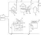
- a cable television (“CATV”) systemtypically includes a supplier 20 that transmits downstream signals, such as radio frequency (“RF”) signals, digital signals, optical signals, etc., to a user through a main signal distribution system 30 and receives upstream signals from a user through the same main signal distribution system 30 .
- a tap 90is located at the main signal distribution system 30 to allow for the passage of the downstream ⁇ upstream signals from ⁇ to the main signal distribution system 30 .
- a drop transmission line 120is then used to connect the tap 90 to a house 10 , 60 , an apartment building 50 , 70 , a coffee shop 80 , and so on.
- a premise device 100 of the present inventionis connected in series or in parallel between the drop transmission line 120 and a user's premise distribution system 130 .
- the premise device 100can be placed at any location between the tap 90 and the user's premise distribution system 130 . This location can be conveniently located within the building 10 , or exterior to the building 60 . Similarly, the premise device 100 can be located within individual apartments of the apartment building 70 or exterior to the apartment building 50 . It should be understood that the premise device 100 can be placed at any location, such as the coffee shop 80 or other business, where CATV services, including internet, VOIP, or other unidirectional ⁇ bidirectional services are being used.
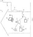
- the user's premise distribution system 130can then be split using a splitter 190 so that upstream/downstream signals can pass to a television 150 and a modem 140 in accordance with practices well known in the art.
- the modem 140can include voice over internet protocol (“VOIP”) capabilities affording telephone 170 services and can include a router affording Internet services to a desktop computer 160 and a laptop computer 180 , for example.
- VOIPvoice over internet protocol
- STBset-top box
- STUset-top unit
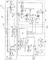
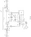
- the premise device 100includes a main circuit 200 that is positioned along with a tuner circuit 600 and a microprocessor circuit 800 .
- the combination of circuits 200 , 600 , 800forms a configurable frequency band selection device 1 (represented separately in FIG. 5 ), an upstream bandwidth conditioning device 2 (represented separately in FIGS. 6 a and 6 b ) and a downstream output level and/or output level tilt compensation device 3 (represented separately in FIG. 8 ), each of which will be discussed separately in greater detail below.
- circuits 200 , 600 , 800 of the premise device 100can be configured to form any combination of the devices such that the premise device 100 may include any one of the devices, any two the devices, or all three of the devices.
- each of the circuitsare positioned within a single enclosure, but it should be understood that circuits 200 , 600 , 800 could be arranged within multiple enclosures to account for space, cost, better resultant performance, or other environmental considerations.
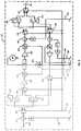
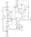
- a circuit 205 of the main circuit 200is represented in FIG. 4 with inputs and outputs between itself and the remaining positions of the circuit 200 in FIG. 3 labeled similarly.
- FIGS. 5, 6 a , 6 b and 8alternate embodiments of the premise device 100 are represented in FIGS. 5, 6 a , 6 b and 8 .
- FIG. 5represents an embodiment of the premise device 100 including only the configurable frequency band selection device 1 .
- FIGS. 6 a and 6 brepresent an embodiment of the premise device 100 including only the upstream bandwidth conditioning device 2 .
- FIG. 8represents an embodiment of the premise device 100 including only the downstream output level and/or output level tilt compensation device 3 . It should be understood that the embodiments shown in FIGS. 5, 6 a , 6 b and 8 are presented to help clarify the components specific to the particular device, and that other embodiments including combinations of these are envisioned.
- microprocessor represented in each of the embodimentsis referenced using the number 810 .
- the microprocessorcould be the same or different across the embodiments depending on the requirements placed thereon.
- the main circuit 200 of the premise device 100includes a supplier side 210 and a premise side 220 .
- the supplier side 210is positioned to receive the downstream bandwidth from the supplier 20 ( FIG. 1 ) and to send the upstream bandwidth to the supplier 20 .
- the premise side 220is positioned to send the downstream bandwidth to the user and to receive the upstream bandwidth from the user.
- Each of the supplier side 210 and the premise side 220can include a traditional threaded 75 ohm connector so that the premise device 100 can be easily placed in series with the drop transmission line 120 and the premise distribution system 130 .
- each of the supplier side 210 and the premise side 220may include a proprietary connecter to hinder attempts at tampering with or theft of the premise device 100 .
- Other connectorsmay also be used depending on the type and/or size of the drop transmission line 120 , the premise distribution system 130 , or a system impedance other than 75 ohms.
- the premise device 100preferably includes a lightening protection device 230 positioned near the supplier side 210 and a lightening protection device 240 positioned near the premise side 220 . Having two lightening protection devices 230 , 240 attempts to protect the premise device 100 from energy passing from the drop transmission line 120 from a lighting strike and from energy passing from the premise distribution system 130 from a lighting strike. It should be understood that the lightening protection devices may not be necessary if/when the premise device 100 is configured to be placed in a CATV system that utilizes non-conductive signal transmission lines. Any of the high quality, commercially available lightning protection devices will function well within the specified locations within the premise device 100 .
- the premise device 100preferably includes two power bypass failure switches 250 , 260 that route all of the upstream ⁇ downstream signals through a bypass signal path 270 (e.g. a coaxial cable, an optical cable, a microstrip, a stripline, etc.) in the event of a power outage.
- the bypass failure switches 250 , 260are preferably located near the supplier end 210 and premise end 220 , respectively. In an effort to protect the bypass failure switches 250 , 260 from damage due to lightening energy, they are preferably placed between the lightening protection devices 230 , 240 and the supplier end 210 and premise end 220 .
- Each of the bypass failure switches 250 , 260includes a default position bypassing the upstream/downstrearn signals through the bypass signal path 270 at any time power is removed from the premise device 100 .
- each of the bypass failure switches 250 , 260actuate to a second position that disconnects the bypass signal path 270 and passes all of the upstream ⁇ downstrearn signal transmissions along another path through the circuit 205 ( FIG. 4 ) within the main circuit 200 .
- the switchesmay also be controlled such that when there is a fault detected in the premise device 100 that could abnormally hinder the flow of the upstream ⁇ downstream bandwidths through the circuit 205 ( FIG.
- the bypass signal path 270can be any suitable coaxial cable or optical cable depending on the CATV system configuration.
- the premise device 100preferably includes circuit components creating the frequency band selection device 1 ( FIG. 5 and represented but not referenced in FIGS. 3 and 4 ).
- the frequency band selection device 1is configured to automatically switch between a configuration corresponding to earlier Data Over Cable Service Interface Specification (“DOCSIS”) specifications and a configuration corresponding to a later generation specification, such as DOCSIS 3.0. While this feature may be advantageous by itself in the premise device 100 , this feature allows for other devices, such as the upstream bandwidth conditioning device 2 and the downstream bandwidth output level and/or output level tilt compensation device 3 , to remain relevant after a change between specifications. In particular, because each of these devices requires an accurate separation of signals between the upstream bandwidth and the downstream bandwidth, any necessary change in the upstream/downstream bandwidths would render these specific devices inoperable. It should be understood that even though the DOCSIS specifications are referenced above and below, the upstream/downstream bandwidth configurations may be maintained and changed according to any specifications.
- DOCSISData Over Cable Service Interface Specification
- the selection device 1includes a plurality of switches 280 , 290 , 300 , 310 , 320 , 330 that define a first signal path set 910 and second signal path set 920 .
- Each signal path setincludes two discrete signal paths, a high frequency signal path 930 and a low frequency signal path 940 .
- the first signal path set 910is formed using a pair of first frequency band splitting devices 340 , 345
- the second signal path set 920is formed using a pair of second frequency band splitting device 350 , 355 .
- a cutoff frequency set by the first pair of frequency band splitting devices 340 , 345corresponds to DOCSIS specifications having a narrower upstream bandwidth
- a cutoff frequency set by the second set pair of frequency band splitting devices 350 , 355corresponds to the later DOCSIS specifications, which include a broader upstream bandwidth than the earlier DOCSIS standards. It should be understood that the cutoff frequencies can be changed to accommodate even newer DOCSIS standards or other standards by the mere replacement of the first pair of frequency band splitting devices 340 , 345 and/or the second pair of frequency band splitting devices 350 , 355 . Any of the high quality, commercially available switches and frequency band splitting devices will function well within the specified locations within the premise device 100 .
- Each of the switches 280 , 290 , 300 , 310 , 320 , 330is controlled either directly or indirectly by a microprocessor 810 ( FIG. 3 ).
- the microprocessor 810determines whether to actuate the switches 280 , 290 , 300 , 310 , 320 , 330 to the first signal path set 910 or to the second signal path set 920 based on an information transmission signal preferably sent by the supplier 20 .
- a signal coupler 360allows for a receiver to 820 to receive the information transmission signal, such as a tone, a coded operational signal, or other well known information transmission, that can be understood by the microprocessor 810 to indicate the switch position.
- the presence of an information signalcan be used to indicate that the microprocessor 810 should select the second signal path set 920 , whereas no information signal could indicate that microprocessor 810 should select the first signal path set 910 .
- the presence of a continuous tone at 900 MHzcan be identified by passing a signal carrying such a tone through a band pass filter 830 to eliminate unnecessary signals and a comparator 840 , which only provides a tone to the microprocessor when/if the tone is stronger than a predetermined threshold determined by a voltage source 850 and a resistive voltage divider 860 .
- the frequencycan be selected by the microprocessor 810 and can be tuned by a phase-locked loop control system 880 and an amplifier 870 in a manner well known in the art. Any of the high quality, commercially available microprocessors, signal couplers and receivers will function well within the specified locations with the premise device 100 .
- the premise device 100preferably further includes circuit components creating the upstream bandwidth conditioning device 2 , which automatically increases the signal to noise ratio of the upstream bandwidth created on the user's premise and passed into the upstream bandwidths on the main signal distribution system 30 .
- the upstream bandwidth conditioning device 2automatically increases the signal to noise ratio of the upstream bandwidth created on the user's premise and passed into the upstream bandwidths on the main signal distribution system 30 .
- the upstream bandwidth conditioning device 2 of one embodiment of the premise device 100includes a variable attenuator 400 and an amplifier 410 .
- the amount of signal level adjustment used to condition the upstream bandwidthis determined by the microprocessor 810 based on inputs from a signal level detector 390 .
- the signal level detector 390measures and maintains a contemporary peak signal strength of the upstream bandwidth via a tap 370 and a filter 380 .
- the microprocessor 810includes a counting circuit, a threshold comparison circuit and a level comparison circuit. It should be understood that even though a microprocessor 810 is used in the present embodiment, it is envisioned to control the variable attenuator 400 in the manner described using a traditional logic circuit.
- another embodiment of the upstream bandwidth conditioning device 2includes a variable amplifier 415 , which is connected and controlled by the 810 .
- an attenuator 405is present and is not controlled by the microprocessor.
- Other embodimentsare envisioned that include both a variable amplifier 415 and a variable attenuator 405 .
- the variable signal level adjustment devicecould also be an automatic gain control circuit (“AGC”) and function well in the current device.
- AGCautomatic gain control circuit
- variable signal level adjustment deviceused herein should be understood to include not only a variable attenuation device, but also circuits containing a variable amplifier, AGC circuits, other variable amplifier/attenuation circuits, and related optical circuits that can be used to reduce the signal strength on the upstream bandwidth.
- contemporary signal strengthis intended to describe a current or present signal strength as opposed to a signal strength measured at a time in the past (i.e., a previous signal strength) such as prior to an application of signal level adjustment or an application of an additional amount of signal level adjustment. The reason for this point should be clear based on the following.
- the microprocessor 810 within the upstream bandwidth conditioning device 2performs a signal level setting routine 1000 ( FIG. 7 ) to determine an appropriate amount of signal level adjustment to apply to the upstream bandwidth via the variable attenuator 400 , the variable amplifier 415 or other suitable variable signal level adjustment device.
- the signal level setting routinecan be run continuously, at predetermined intervals, and/or on command as a result of an information signal transmitted by the supplier 20 .
- the microprocessor 810 or logic circuitperforms the signal level setting routine in accordance with the flow chart shown in FIG. 7 .
- the counting circuit in the microprocessor 810is reset to zero (0), for example, in step 1020 .
- the microprocessor 810iteratively performs steps 1030 , 1040 , 1050 , 1060 , 1070 , 1080 and 1090 until the counter reaches a predetermined number (e.g. 25) or the answer to step 1080 is negative.
- step 1030the microprocessor 810 reads a contemporary signal strength from the signal level detector 390 , and the counter is incremented by a predetermined increment, such as one (1) in step 1040 .
- the microprocessor 810looks to see if the counter is greater than the predetermined number (i.e., 25). If so, the microprocessor 810 ends the routine, but if not, the microprocessor 810 proceeds to step 1060 .
- the microprocessor 810compares the contemporary signal strength to a predetermined threshold. If the contemporary signal strength is greater than the predetermined threshold, the microprocessor 810 instructs the variable attenuator 400 to add an amount of additional signal level adjustment (e.g. 1 dB), but if the contemporary signal strength is lower than the predetermined threshold, the microprocessor 810 returns to step 1030 .
- a predetermined incrementsuch as one (1) in step 1040 .
- the microprocessor 810looks to see if the counter is greater than the predetermined number (i.e., 25). If
- the microprocessor 810After adding the amount of additional signal level adjustment, the microprocessor 810 reads a new contemporary signal strength in step 1080 while saving the previously read contemporary signal strength (i.e., from step 1030 ) as a previous signal strength in preparation for step 1090 .
- the microprocessor 810compares the contemporary signal strength measured in step 1080 and the previous signal strength measured in step 1030 to one another. If the contemporary signal strength is equal to the previous signal strength then the microprocessor 810 returns to step 1030 , but if the contemporary signal strength is less than the previous signal strength the microprocessor 810 proceeds to step 1100 where it instructs the variable attenuator 400 to reduce the amount of signal level adjustment by a predetermined amount (e.g.
- step 1070the amount of additional signal level adjustment added in step 1070 or an amount greater than the additional signal level adjustment added in step 1070 ).
- the microprocessor 810saves the total amount of signal level adjustment in step 1110 and stops the routine at step 1120 .
- the amount of additional signal level adjustmentmay be added/removed by the variable amplifier 415 , or by the AGC discussed above.
- a traditional cable modem 140used in CATV systems can adjust its output level based on information signals received from the suppler in the downstream bandwidth.
- the supplier 20instructs the modem 140 to increase its transmission signal level.
- the modem 140will continually increase signal level as a result of increased amounts of upstream bandwidth signal level adjustment until the modem 140 can no longer increase its transmission signal strength.
- the contemporary signal strength measured in step 1080 after the addition of additional signal level adjustment in step 1070should be equal to the previous signal strength if the modem 140 is able to compensate for the additional signal level adjustment.
- the modem 140is already producing its maximum signal strength, the contemporary signal strength will be less than the previous signal strength when an additional amount of upstream bandwidth signal level adjustment is applied.
- the amount of signal level adjustmentmay be reduced by a sufficient amount in step 1100 to ensure quality of the output signal generated by the modem 140 and the durability of the modem 140 once the maximum output strength of the modem 140 is identified.
- the premise device 100may identify the maximum output strength of one device and not the other. In other words, the premise device 100 may identify the first device achieving its maximum output strength without proceeding to identify the maximum output strength of any other devices. If the premise device 100 fails to identify the first observed maximum output strength, that device may continue to operate at its maximum output strength until another determination cycle is initiated.
- the predetermined number compared in 1050can be related directly to the amount of signal level adjustment.
- the variable signal level adjustment deviceis a step attenuator including 25 steps of 1 dB attenuation, as is the case in the embodiment represented in FIG. 6 a
- the predetermined numbercan be set to 25 to allow for the finest resolution (i.e., 1 dB) and the broadest use of the particular step attenuator's range (i.e., 25 dB). It should be understood that the number of steps could be reduced and the resolution could be decreased (i.e., 5 steps of 5 dB) if faster overall operation is desired.
- the predetermined numbercould be increased if a variable signal level adjustment device having a finer resolution (i.e., less than 1 dB) or a broader range (i.e., greater than 25 dB) is utilized.
- the incremented amount discussed here relating the counter and the predetermined numberis one (1) such that there are 25 iterations (i.e., 25 steps) when the predetermined number is 25.
- the incrementcould easily be any number (i.e., 1, 5, 10, ⁇ 1, ⁇ 10, etc.) depending on the predetermined number and the total number of steps desired, which, as discussed above, is based on the desired resolution and the desired range of signal level adjustment.
- the amount of additional attenuation added in step 1070 , and the predetermined amount of attenuation reduced in step 1100are all variables that are currently based, at least partially, on hardware design limitations and can, depending on the hardware, be adjusted by one skilled in the art based on the conditions experienced in a particular CATV system and with particular CATV equipment.
- the variable signal level adjustment device in one embodiment of the present inventionis a step attenuator having a resolution of 1 dB and a range of 25 dB. Accordingly, the amount of additional attenuation added in step 1070 using the present hardware could be 1 dB or multiples of 1 dB.
- the predetermined amount of attenuation reduced in step 1100can be 1 dB or multiples of 1 dB. It should be understood that if the amount of additional attenuation added in step 1070 is a multiple of 1 dB, such as 5 dB, the amount of attenuation reduced in step 1100 can be a lesser amount, such as 2 dB or 4 dB. The amount of attenuation reduced in step 1100 can also be greater than the amount of additional attenuation added in step 1070 for the reasons stated above relating to maintaining the quality of the output from the modern 140 and the and durability of the modem 140 .
- the predetermined threshold compared in step 1060is a signal level sufficient to distinguish the presence of upstream data packets in the upstream bandwidth from interference signals. This value will vary depending on the output power of any cable modem 140 , STB, STU, etc. in the system and the average observed level of interference signals. A goal is, for example, to determine if a device is present that sends upstream data packets via the upstream bandwidth. If the predetermined threshold is set too low, the interference signals may appear to be upstream data packets, but if the predetermined threshold is set too high, the upstream data packets may appear as interference signals.
- any of the high quality, commercially available signal couplers, signal level detectors, variable attenuation devices, filters, amplifiers, and microprocessorswill function well within the specified locations within the premise device 100 .
- the premise device 100preferably includes circuit components creating the downstream bandwidth output level and/or output level tilt compensation device 3 , which helps to maintain a desired signal quality in transmitted signals using relatively high frequencies within the downstream bandwidth, which are much more susceptible to traditional parasitic losses.
- the microprocessor 810observes channel data obtained from the tuner circuit 600 , compares the observed channel data to a known parasitic loss curve, and then adjusts a pair of variable output level compensation devices 440 , 450 and a variable slope adjusting circuit 460 located in the circuit 200 to create an output having a desired gain curve (i.e., a curve representative of transmitted signal strengths) across the downstream bandwidth.
- a desired gain curvei.e., a curve representative of transmitted signal strengths
- variable output level compensation devices 440 , 450are depicted in FIGS. 4 and 8 as a variable attenuator, it should be understood that the term “variable output level compensation device” used herein should be understood to include not only a variable attenuation device, but also circuits containing a variable amplifier, AGO circuits, other variable amplifier/attenuation circuits, and related optical circuits that can be used to alter the signal strength of signals in the downstream bandwidth. Each of these steps will be discussed in further detail below.
- the tuner circuit 600obtains the downstream bandwidth from a coupler 420 drawing the downstream bandwidth off of the high frequency signal path 930 ( FIG. 5 ). Please note that these signals will be referred to herein as the coupled downstream bandwidth.
- the coupled downstream bandwidthis passed through a resistor 430 prior to being passed into a tuner 610 .
- the tuner 610scans the coupled downstream bandwidth in an effort to locate and identify a channel having a low frequency, referred to herein as a low band signal channel 1250 ( FIG. 9 ), and a channel having a high frequency, referred to herein as a high band signal channel 1260 ( FIG. 9 ).
- the microprocessor 810instructs the tuner 610 to begin at the lowest frequency in the downstream bandwidth and scan toward higher frequencies until the low band signal channel 1250 is found.
- the microprocessor 810instructs the tuner 610 to begin at the highest frequency in the coupled downstream bandwidth and scan toward lower frequencies until the high band signal channel 1260 is found.
- the low band signal channel 1250is a channel located near the lowest frequency within the coupled downstream bandwidth while the high band channel 1260 is a channel located near the highest frequency within the coupled downstream bandwidth.
- a channelis typically a range of frequencies.
- the low band signal channel 1250 and the high band signal channel 1260do not need to be the lowest or highest frequency channels, respectively. It is beneficial, however that the two channels be spaced as far apart from one another as practical to better estimate the amount of parasitic loss experiences across the entire downstream bandwidth.
- the tuner circuit 600provides the microprocessor 810 with three types of information. First, a signal indicating that a channel has been identified is provided to the microprocessor 810 through input line 640 . Second, a signal indicating signal strength of the identified channel is provided to the microprocessor 810 through input line 630 . Third, a signal indicating the format of the identified channel is provided to the microprocessor 810 through input line 620 .
- the signal indicating that a channel has been identifiedis created by passing the coupled downstream bandwidth though a band pass filter 650 to remove extraneous noise, a signal level detector 660 to convert signal into a voltage, and another signal level detector 670 .
- the signal leaving the signal level detector 670is compared to a predetermined threshold voltage using comparator 680 .
- the predetermined threshold voltageis created using a voltage source 690 and an resistive divider 700 , and is set such that if the voltage associated with the coupled downstream bandwidth at the tuner frequency is greater than the threshold voltage, it is likely a channel in use by the supplier 20 , whereas if the voltage associated with the coupled downstream bandwidth at the tuner frequency is less than the threshold voltage, it is likely interference signals.
- the signal indicating signal strengthis created similarly to the signal indicating that a channel has been identified.
- the signal indicating signal strengthpasses through comparator 720 when it is greater than a threshold voltage created by a voltage source 730 and a resistive divider 740 .
- the signal indicating that a channel has been identifiedmay not have any direct relation to the actual signal strength, whereas the signal indicating signal strength is directly proportional to the actual signal strength of the identified channel.
- the signal indicating the format of the identified channelis created when the coupled downstream bandwidth passes through a channel analyzer, which includes the band pass filter 650 , the signal level detector 660 , a synch detector 750 , a low pass filter 760 , and a signal level detector 770 .
- the resulting signalidentifies whether the identified channel is an analog format channel or another type of signal format.
- digital format channelshave a signal strength that is typically 6 dB less than a corresponding analog channel. Accordingly, the microprocessor 810 must include a level offset calculation that can account for this 6 dB difference when comparing the relative signal strengths of the low and high band signal channels 1250 , 1260 . If this inherent difference is not accounted for, any resulting comparisons of the two channels 1250 , 1260 for the purpose of determining relative signal strengths would necessarily be flawed. For example, if the high band channel 1260 is digital while the low band channel 1250 is analog, the additional, inherent 6 dB difference would incorrectly indicate that there is more parasitic losses than there actually is.
- the 6 dB offsetcan be added to the signal strength of both the low and high band channels 1250 , 1260 if they are both digital or the 6 dB offset can be subtracted from the signal strength of both the low and high band channels 1250 , 1260 if they are both analog, Even further, it should be understood that the offset value is dictated by the standards observed by a particular supplier and can be, therefore, a value other than 6 dB.
- the microprocessor 810After completing the scanning process and the process of adding/removing any offsets, the microprocessor 810 now has a low band signal strength (including any offset), a low band channel frequency, a high band signal strength (including any offset), and a high band channel frequency.
- the known information (i.e., the strength and frequency) of the low and high band channels 1250 , 1260are now compared, by the microprocessor 810 , to a predetermined signal strength loss curve (i.e., a gain loss curve), which corresponds to the known parasitic losses associated with the type of coaxial/optical cables used, as shown in FIG. 9 .
- This stepbeneficially allows the known information to be interpolated across the entire downstream bandwidth.
- the microprocessor 810determines how much signal level adjustment to apply and in what manner to apply the level adjustment across the entire downstream bandwidth such that the a resulting gain curve across the entire bandwidth is nearly linear and preferably with a slight increase in gain toward the higher frequencies in anticipation of parasitic losses that will occur downstream from the premise device 100 .
- the amount of levelis determined by the high band signal strength (i.e., high band gain) including any interpolation to the highest frequency
- the amount of level reductionis determined by the low band signal strength (i.e., low band level) including any interpolation to the lowest frequency.
- a gain curve 1210can be plotted across the entire downstream bandwidth, which is shown, for example, as being from 50 MHz to 1000 MHz.
- the microprocessor 810determines a total amount of level adjustment to be added by the amplifier 490 and/or the amplifier 500 that will at least replace the loss at the highest frequency. In the present example, the amount of level adjustment would be at least +38 dB, resulting in a gain curve 1220 that is shown in FIG. 10 . Based on the interpolated gain curve shown in FIG.
- the microprocessor 810instructs the variable slope circuit 460 to apply a similar, but inversely curved amount of correction to result in a relatively flat gain curve 1230 shown in FIG. 10 . It may be desirable to increase the amount of level adjustment applied and increase the curvature of the slope adjustment to result in a gain curve 1240 , as shown in FIG. 8 , which has an increasing slope toward the higher frequencies.
- the downstream bandwidth output level and/or output level tilt compensation device 3can be activated automatically upon initialization of the premise device 100 , a set intervals, upon the occurrence of a particular event, and/or upon receipt of an information signal (e.g. a tone, a coded operating signal, etc.) from the supplier 20 .
- an information signale.g. a tone, a coded operating signal, etc.
Landscapes
- Engineering & Computer Science (AREA)
- Signal Processing (AREA)
- Multimedia (AREA)
- Computer Networks & Wireless Communication (AREA)
- Two-Way Televisions, Distribution Of Moving Picture Or The Like (AREA)
Abstract
Description
Claims (76)
Priority Applications (1)
| Application Number | Priority Date | Filing Date | Title |
|---|---|---|---|
| US16/280,277US10924811B2 (en) | 2008-10-16 | 2019-02-20 | Compensation device for maintaining a desired signal quality in transmitted signals |
Applications Claiming Priority (4)
| Application Number | Priority Date | Filing Date | Title |
|---|---|---|---|
| US12/252,907US8832767B2 (en) | 2008-10-16 | 2008-10-16 | Dynamically configurable frequency band selection device between CATV distribution system and CATV user |
| US14/337,424US9271026B2 (en) | 2008-10-16 | 2014-07-22 | Dynamically configurable frequency band selection device between CATV distribution system and CATV user |
| US15/049,661US10264325B2 (en) | 2008-10-16 | 2016-02-22 | System, method and device having teaching and commerce subsystems |
| US16/280,277US10924811B2 (en) | 2008-10-16 | 2019-02-20 | Compensation device for maintaining a desired signal quality in transmitted signals |
Related Parent Applications (1)
| Application Number | Title | Priority Date | Filing Date |
|---|---|---|---|
| US15/049,661ContinuationUS10264325B2 (en) | 2008-10-16 | 2016-02-22 | System, method and device having teaching and commerce subsystems |
Publications (2)
| Publication Number | Publication Date |
|---|---|
| US20190182555A1 US20190182555A1 (en) | 2019-06-13 |
| US10924811B2true US10924811B2 (en) | 2021-02-16 |
Family
ID=42109661
Family Applications (4)
| Application Number | Title | Priority Date | Filing Date |
|---|---|---|---|
| US12/252,907Expired - Fee RelatedUS8832767B2 (en) | 2008-10-16 | 2008-10-16 | Dynamically configurable frequency band selection device between CATV distribution system and CATV user |
| US14/337,424Expired - Fee RelatedUS9271026B2 (en) | 2008-10-16 | 2014-07-22 | Dynamically configurable frequency band selection device between CATV distribution system and CATV user |
| US15/049,661ActiveUS10264325B2 (en) | 2008-10-16 | 2016-02-22 | System, method and device having teaching and commerce subsystems |
| US16/280,277Expired - Fee RelatedUS10924811B2 (en) | 2008-10-16 | 2019-02-20 | Compensation device for maintaining a desired signal quality in transmitted signals |
Family Applications Before (3)
| Application Number | Title | Priority Date | Filing Date |
|---|---|---|---|
| US12/252,907Expired - Fee RelatedUS8832767B2 (en) | 2008-10-16 | 2008-10-16 | Dynamically configurable frequency band selection device between CATV distribution system and CATV user |
| US14/337,424Expired - Fee RelatedUS9271026B2 (en) | 2008-10-16 | 2014-07-22 | Dynamically configurable frequency band selection device between CATV distribution system and CATV user |
| US15/049,661ActiveUS10264325B2 (en) | 2008-10-16 | 2016-02-22 | System, method and device having teaching and commerce subsystems |
Country Status (1)
| Country | Link |
|---|---|
| US (4) | US8832767B2 (en) |
Families Citing this family (28)
| Publication number | Priority date | Publication date | Assignee | Title |
|---|---|---|---|---|
| US9363469B2 (en) | 2008-07-17 | 2016-06-07 | Ppc Broadband, Inc. | Passive-active terminal adapter and method having automatic return loss control |
| US9647851B2 (en) | 2008-10-13 | 2017-05-09 | Ppc Broadband, Inc. | Ingress noise inhibiting network interface device and method for cable television networks |
| US8385219B2 (en) | 2009-10-09 | 2013-02-26 | John Mezzalingua Associates, Inc. | Upstream bandwidth level measurement device |
| US20110085586A1 (en)* | 2009-10-09 | 2011-04-14 | John Mezzalingua Associates, Inc. | Total bandwidth conditioning device |
| US8213457B2 (en)* | 2009-10-09 | 2012-07-03 | John Mezzalingua Associates, Inc. | Upstream bandwidth conditioning device |
| US8464301B2 (en)* | 2008-10-16 | 2013-06-11 | Ppc Broadband, Inc. | Upstream bandwidth conditioning device between CATV distribution system and CATV user |
| US8516537B2 (en)* | 2009-10-09 | 2013-08-20 | Ppc Broadband, Inc. | Downstream bandwidth conditioning device |
| US11910052B2 (en) | 2008-10-21 | 2024-02-20 | Ppc Broadband, Inc. | Entry device for communicating external network signals and in-home network signals |
| US8510782B2 (en) | 2008-10-21 | 2013-08-13 | Ppc Broadband, Inc. | CATV entry adapter and method for preventing interference with eMTA equipment from MoCA Signals |
| US20110138440A1 (en)* | 2009-12-03 | 2011-06-09 | John Mezzalingua Associates, Inc. | Downstream output level tilt compensation device between CATV distribution system and CATV user |
| US8479247B2 (en) | 2010-04-14 | 2013-07-02 | Ppc Broadband, Inc. | Upstream bandwidth conditioning device |
| US8707339B2 (en)* | 2010-07-30 | 2014-04-22 | CSC Holdings, LLC | System and method for detecting hacked modems |
| US8561125B2 (en) | 2010-08-30 | 2013-10-15 | Ppc Broadband, Inc. | Home network frequency conditioning device and method |
| WO2012088350A2 (en) | 2010-12-21 | 2012-06-28 | John Mezzalingua Associates, Inc. | Method and apparatus for reducing isolation in a home network |
| US9021086B2 (en)* | 2011-10-21 | 2015-04-28 | Comcast Cable Communications, Llc | System and method for network management |
| US8971792B2 (en)* | 2012-06-25 | 2015-03-03 | Commscope, Inc. Of North Carolina | Signal amplifiers that switch to an attenuated or alternate communications path in response to a power interruption |
| US8995912B2 (en)* | 2012-12-03 | 2015-03-31 | Broadcom Corporation | Transmission line for an integrated circuit package |
| KR102424757B1 (en)* | 2015-08-18 | 2022-07-22 | 인터디지털 씨이 페이튼트 홀딩스, 에스에이에스 | Method and apparatus for controlling a filter circuit in a signal communication device |
| US9935661B2 (en) | 2016-02-16 | 2018-04-03 | Thomson Licensing | Apparatus and method for controlling a filter in a signal communication device |
| US10701569B2 (en) | 2016-10-03 | 2020-06-30 | Enseo, Inc. | Self-calibrating RF network and system and method for use of the same |
| US10425617B2 (en) | 2016-10-03 | 2019-09-24 | Enseo, Inc. | Distribution element for a self-calibrating RF network and system and method for use of the same |
| US11831934B2 (en) | 2022-01-11 | 2023-11-28 | Enseo, Llc | Set-top box with self-monitoring and system and method for use of same |
| US12212792B2 (en) | 2016-10-28 | 2025-01-28 | Enseo, Llc | Set-top box with self-monitoring and system and method for use of same |
| US10798374B2 (en) | 2016-10-28 | 2020-10-06 | Enseo, Inc. | Set-top box with self-monitoring and system and method for use of same |
| EP3471406A1 (en)* | 2017-10-13 | 2019-04-17 | Teleste Oyj | An arrangement for catv network |
| US11502716B2 (en)* | 2020-12-16 | 2022-11-15 | Texas Instruments Incorporated | On-off keying receivers |
| US12193718B2 (en) | 2021-04-09 | 2025-01-14 | Smith & Nephew, Inc. | Orthopedic surgical instrument |
| US11962400B2 (en)* | 2021-05-03 | 2024-04-16 | Arris Enterprises Llc | System for channel map delivery for hi split cable networks |
Citations (130)
| Publication number | Priority date | Publication date | Assignee | Title |
|---|---|---|---|---|
| US3790909A (en) | 1973-01-26 | 1974-02-05 | Gte Sylvania Inc | Varactor tuner band switch circuitry |
| US4007487A (en)* | 1975-09-25 | 1977-02-08 | The Association Of Motion Picture And Television Producers Inc. | Electronic composite photography with color control |
| JPS5580989A (en) | 1978-12-15 | 1980-06-18 | Nec Corp | Automatic balancing system for exchange |
| JPS55132126A (en) | 1979-03-31 | 1980-10-14 | Fujitsu Ltd | Selective switching circuit of signal transmission line |
| JPS5791055A (en) | 1980-11-27 | 1982-06-07 | Toshiba Corp | Branching device |
| JPS5899913A (en) | 1981-12-10 | 1983-06-14 | 松下電工株式会社 | Chair |
| JPS58101582U (en) | 1974-11-14 | 1983-07-11 | エヌ・ベ−・フイリツプス・フル−イランペンフアブリケン | display tube |
| US4418424A (en) | 1980-03-17 | 1983-11-29 | Matsushita Electric Industrial Co., Ltd. | Cable television transmission control system |
| US4512033A (en) | 1982-11-29 | 1985-04-16 | C-Cor Labs, Inc. | Remote level adjustment system for use in a multi-terminal communications system |
| US4520508A (en) | 1982-12-21 | 1985-05-28 | General Instrument Corporation | Subscriber terminal for monitoring radio-frequency signal ingress into cable television systems |
| US4521920A (en) | 1980-09-01 | 1985-06-04 | Telefonaktiebolaget L M Ericsson | Method and an arrangement for increasing the dynamic range at the input stage of a receiver in an optical fibre information transmission system |
| JPS61157035A (en) | 1984-12-28 | 1986-07-16 | Fujitsu Ltd | Impedance matching system |
| US4648123A (en) | 1982-11-29 | 1987-03-03 | C-Cor Labs, Inc. | Remote level measurement system for use in a multi-terminal communications system |
| US4677390A (en) | 1985-05-31 | 1987-06-30 | Texscan Corporation | Low-power feedforward amplifier |
| US4961218A (en) | 1989-05-17 | 1990-10-02 | Tollgrade Communications, Inc. | Enhanced line powered amplifier |
| US4982440A (en) | 1988-04-21 | 1991-01-01 | Videotron Ltee | CATV network with addressable filters receiving MSK upstream signals |
| US5010399A (en) | 1989-07-14 | 1991-04-23 | Inline Connection Corporation | Video transmission and control system utilizing internal telephone lines |
| US5126840A (en) | 1988-04-21 | 1992-06-30 | Videotron Ltee | Filter circuit receiving upstream signals for use in a CATV network |
| US5214505A (en) | 1991-04-08 | 1993-05-25 | Hughes Aircraft Company | Automatic rf equalization in passenger aircraft video distribution system |
| US5231660A (en)* | 1988-03-10 | 1993-07-27 | Scientific-Atlanta, Inc. | Compensation control for off-premises CATV system |
| JPH05191416A (en) | 1992-01-10 | 1993-07-30 | Matsushita Electric Ind Co Ltd | Automatic termination resistor connector |
| US5235612A (en) | 1990-12-21 | 1993-08-10 | Motorola, Inc. | Method and apparatus for cancelling spread-spectrum noise |
| US5345504A (en) | 1988-03-10 | 1994-09-06 | Scientific-Atlanta, Inc. | Differential compensation control for off-premises CATV system |
| US5361394A (en) | 1989-12-19 | 1994-11-01 | Kabushiki Kaisha Toshiba | Upstream signal control apparatus for cable television system |
| US5369642A (en) | 1992-05-29 | 1994-11-29 | Nec Corporation | Switcher for redundant signal transmission system |
| JPH0738580A (en) | 1993-06-28 | 1995-02-07 | Nec Corp | Variable terminating system |
| US5548255A (en) | 1995-06-23 | 1996-08-20 | Microphase Corporation | Compact diplexer connection circuit |
| US5745836A (en) | 1995-09-01 | 1998-04-28 | Cable Television Laboratories, Inc. | Undesirable energy suppression system in a contention based communication network |
| US5815794A (en) | 1995-09-01 | 1998-09-29 | Cable Television Laboratories, Inc. | Undesirable energy suppression system in the return path of a bidirectional cable network having dynamically allocated time slots |
| US5839052A (en) | 1996-02-08 | 1998-11-17 | Qualcom Incorporated | Method and apparatus for integration of a wireless communication system with a cable television system |
| JPH1169334A (en) | 1997-08-19 | 1999-03-09 | Miharu Tsushin Kk | Standby tv modulator for catv head end |
| US5893024A (en) | 1996-08-13 | 1999-04-06 | Motorola, Inc. | Data communication apparatus and method thereof |
| US5937330A (en) | 1997-02-18 | 1999-08-10 | General Instrument Corporation | Settop terminal controlled return path filter for minimizing noise ingress on bidirectional cable systems |
| US5950111A (en) | 1997-09-25 | 1999-09-07 | Lucent Technologies Inc. | Self-terminating coaxial to unshielded twisted-pair cable passive CATV distribution panel |
| US5956075A (en) | 1996-07-22 | 1999-09-21 | Nec Corporation | CATV terminal unit |
| US5970053A (en) | 1996-12-24 | 1999-10-19 | Rdl, Inc. | Method and apparatus for controlling peak factor of coherent frequency-division-multiplexed systems |
| US6014547A (en) | 1997-04-28 | 2000-01-11 | General Instrument Corporation | System for enhancing the performance of a CATV settop terminal |
| US6049693A (en) | 1996-08-15 | 2000-04-11 | Com21, Inc. | Upstream ingress noise blocking filter for cable television system |
| WO2000024124A1 (en) | 1998-10-22 | 2000-04-27 | Ericsson, Inc. | Dual-band, dual-mode power amplifier with reduced power loss |
| US6069960A (en) | 1996-09-05 | 2000-05-30 | Sony Corporation | Connector device for information-handling apparatus and connector device for stereophonic audio/video apparatus |
| US6160990A (en) | 1996-05-13 | 2000-12-12 | Kabushiki Kaisha Toshiba | Cable network system with ingress noise suppressing function |
| US6205138B1 (en) | 1998-04-24 | 2001-03-20 | International Business Machines Corporation | Broadband any point to any point switch matrix |
| US6208846B1 (en) | 1997-01-13 | 2001-03-27 | Lucent Technologies, Inc. | Method and apparatus for enhancing transmitter circuit efficiency of mobile radio units by selectable switching of power amplifier |
| US6253077B1 (en) | 1997-05-16 | 2001-06-26 | Texas Instruments Incorporated | Downstream power control in point-to-multipoint systems |
| JP2001177580A (en) | 1999-12-20 | 2001-06-29 | Sony Corp | Impedance adapting system |
| WO2001072005A1 (en) | 2000-03-17 | 2001-09-27 | Transcorp Systems Pty Ltd | Digital data splitter with switch and automatic termination restoration |
| US6348837B1 (en) | 2000-08-08 | 2002-02-19 | Scientific-Atlanta, Inc. | Bi-directional amplifier having a single gain block for amplifying both forward and reverse signals |
| US6348955B1 (en) | 1998-02-23 | 2002-02-19 | Zenith Electronics Corporation | Tuner with switched analog and digital demodulators |
| US6373349B2 (en) | 2000-03-17 | 2002-04-16 | Bae Systems Information And Electronic Systems Integration Inc. | Reconfigurable diplexer for communications applications |
| US6377316B1 (en) | 1998-02-23 | 2002-04-23 | Zenith Electronics Corporation | Tuner with switched analog and digital modulators |
| WO2002033969A1 (en) | 2000-10-16 | 2002-04-25 | Xtend Networks Ltd. | System and method for expanding the operational bandwidth of a communication system |
| US6388539B1 (en) | 2001-04-16 | 2002-05-14 | At&T Corp. | Broadband switch/coupler |
| US6425132B1 (en) | 1998-04-06 | 2002-07-23 | Wavetek Corporation | Ingress testing of CATV system utilizing remote selection of CATV node |
| US20020144292A1 (en) | 2001-02-19 | 2002-10-03 | Jun Uemura | Bi-directional CATV system, line equipment, center equipment |
| US20020141347A1 (en) | 2001-03-30 | 2002-10-03 | Harp Jeffrey C. | System and method of reducing ingress noise |
| US20020141494A1 (en) | 2001-03-29 | 2002-10-03 | Chappell Daniel K. | Sweep method using digital signals |
| US20020166124A1 (en) | 2001-05-04 | 2002-11-07 | Itzhak Gurantz | Network interface device and broadband local area network using coaxial cable |
| WO2002091676A1 (en) | 2001-05-08 | 2002-11-14 | Hoseo Telecom Co., Ltd | Subscriber tap-off capable of monitoring state of transmission line at subscriber end, and remote control system and method using the same |
| US20020174435A1 (en) | 2001-02-27 | 2002-11-21 | Hillel Weinstein | System, apparatus and method for expanding the operational bandwidth of a communication system |
| US6495998B1 (en) | 2000-09-28 | 2002-12-17 | Sunrise Telecom Corp. | Selectable band-pass filtering apparatus and method |
| US20020191718A1 (en)* | 2001-06-13 | 2002-12-19 | Ellis Michael Glynn | Method and apparatus for automatically compensating for attenuation in a received signal |
| US6498925B1 (en) | 1999-05-13 | 2002-12-24 | Denso Corporation | Transmit power control circuit |
| US6510152B1 (en) | 1997-12-31 | 2003-01-21 | At&T Corp. | Coaxial cable/twisted pair fed, integrated residence gateway controlled, set-top box |
| US6560778B1 (en) | 1999-03-29 | 2003-05-06 | Masprodenkoh Kabushikikaisha | Tap device of cable broadcasting system |
| US6570914B1 (en) | 1999-07-07 | 2003-05-27 | Nec Corporation | Amplitude calculation circuit |
| US6570928B1 (en) | 1999-01-05 | 2003-05-27 | Masprodenkoh Kabushikikaisha | Cable broadcasting system |
| US6587012B1 (en) | 1999-10-01 | 2003-07-01 | Arris International, Inc. | Automatic slope and gain (ASG) detector technique including a pilot signal |
| US20030149991A1 (en)* | 2002-02-07 | 2003-08-07 | Reidhead Lance R. | Radio frequency characterization of cable plant and corresponding calibration of communication equipment communicating via the cable plant |
| US6622304B1 (en) | 1996-09-09 | 2003-09-16 | Thomas W. Carhart | Interface system for computing apparatus and communications stations |
| US6640338B1 (en) | 1999-01-27 | 2003-10-28 | Masprodenkoh Kabushikikaisha | Electronic device for cable broadcasting system |
| US6653751B1 (en) | 2000-09-12 | 2003-11-25 | Storage Technology Corporation | Fault tolerant AC transfer switch |
| US6678893B1 (en) | 1997-12-26 | 2004-01-13 | Samsung Electronics Co., Ltd. | Bidirectional trunk amplifier and cable modem for cable hybrid fiber and coax network which utilizes an upstream pilot signal |
| US6683513B2 (en) | 2000-10-26 | 2004-01-27 | Paratek Microwave, Inc. | Electronically tunable RF diplexers tuned by tunable capacitors |
| JP2004080483A (en) | 2002-08-20 | 2004-03-11 | Ntt Communications Kk | Adapter for VoIP |
| US6725463B1 (en) | 1997-08-01 | 2004-04-20 | Microtune (Texas), L.P. | Dual mode tuner for co-existing digital and analog television signals |
| US6725462B1 (en) | 2000-04-19 | 2004-04-20 | At&T Corp. | Optimizing upstream transmission in a cable television distribution plant |
| US20040076192A1 (en) | 1999-10-19 | 2004-04-22 | Rambus Inc. | Calibrated data communication system and method |
| US6728968B1 (en) | 1999-06-17 | 2004-04-27 | Fujitsu Limited | Upward-joining-noise decreasing method and apparatus |
| US6757910B1 (en) | 2000-06-08 | 2004-06-29 | C-Cor.Net Corporation | Adaptive filter for reducing ingress noise in CATV return signals |
| US20040172659A1 (en) | 2001-07-13 | 2004-09-02 | Ljungdahl Kjell Arne | Arrangement for reduction of noise transmitted from a local cable tv network |
| US6804828B1 (en) | 1998-12-03 | 2004-10-12 | Masprodenkoh Kabushikikaisha | Tap device of cable broadcasting system |
| US20040229561A1 (en) | 2003-02-28 | 2004-11-18 | Cowley Nicholas Paul | Tuner |
| US20040261121A1 (en)* | 2003-04-29 | 2004-12-23 | Bishop Donald M. | Distributed gain network |
| JP2005005875A (en) | 2003-06-10 | 2005-01-06 | Nec Tohoku Ltd | VoIP SWITCHING DEVICE |
| US6845232B2 (en) | 2002-03-25 | 2005-01-18 | Broadcom Corporation | Analog peak detection circuitry for radio receivers |
| US6877166B1 (en) | 2000-01-18 | 2005-04-05 | Cisco Technology, Inc. | Intelligent power level adjustment for cable modems in presence of noise |
| US6880170B1 (en) | 1994-11-30 | 2005-04-12 | General Instrument Corporation | Ingress detection and attenuation |
| US20050155082A1 (en) | 2001-02-27 | 2005-07-14 | Hillel Weinstein | Device, system and method for connecting a subscriber device to a wideband distribution network |
| US6928175B1 (en) | 2000-06-14 | 2005-08-09 | Creative Technology Ltd. | Audio system with optional auto-switching secondary connector, and method for same |
| US20050183130A1 (en) | 2004-02-12 | 2005-08-18 | Sadja Aran L. | Cable diagnostic and monitoring system |
| US20050283815A1 (en) | 2004-06-01 | 2005-12-22 | Brooks Paul D | Apparatus and methods for network interface and spectrum management |
| US20050289632A1 (en) | 2004-06-01 | 2005-12-29 | Brooks Paul D | Controlled isolation splitter apparatus and methods |
| US20060012921A1 (en) | 2004-07-13 | 2006-01-19 | Fujitsu Limited | Carriage assembly of a hard disk drive |
| US7003275B1 (en) | 2000-05-18 | 2006-02-21 | Broadband Innovations, Inc. | Agile frequency converter for multichannel systems using IF-RF level exhange and tunable filters |
| US7029293B2 (en) | 2004-08-20 | 2006-04-18 | Extreme Broadband Engineering, Llc | Ground block connector |
| US7039432B2 (en) | 2001-12-04 | 2006-05-02 | General Instrument Corporation | Dynamic upstream attenuation for ingress noise reduction |
| US20060205442A1 (en) | 2005-03-10 | 2006-09-14 | Neil Phillips | Bi-directional amplifier with non-interruptible port |
| US20060282871A1 (en) | 2005-06-13 | 2006-12-14 | Yao-Tsan Yo | Distribution method for noise control |
| US7167693B2 (en) | 2001-03-06 | 2007-01-23 | Andrew Corporation | Scanning receiver for use in power amplifier linearization |
| JP2007166110A (en) | 2005-12-12 | 2007-06-28 | Matsushita Electric Works Ltd | Transmission system and branch device thereof |
| JP2007166109A (en) | 2005-12-12 | 2007-06-28 | Matsushita Electric Works Ltd | Branch device of transmission system, and transmission system |
| US7283479B2 (en) | 2000-02-16 | 2007-10-16 | Spacenet Proxilliant Systems Ab | Cable TV system or other similar communication system |
| US20070288982A1 (en) | 2006-06-13 | 2007-12-13 | Comcast Cable Holdings, Llc | Dynamic ingress arrester |
| US20070288981A1 (en) | 2006-06-13 | 2007-12-13 | Hwa Lin Electronic (Shenzhen)Co., Ltd. | CATV system and automatic noise controller |
| CN101094375A (en) | 2006-12-29 | 2007-12-26 | 雷科通技术(杭州)有限公司 | Method and device for carrying out remote both way communications by using cable TV network |
| US20070300284A1 (en)* | 2006-06-23 | 2007-12-27 | Rgb Systems, Inc., (Dba Extron Electronics) | Method and apparatus for automatic compensation of video signal losses from transmission over conductors |
| US20080022344A1 (en) | 2006-07-07 | 2008-01-24 | Scientific-Atlanta, Inc. | Format Converter with Smart Multitap with Digital Forward and Reverse |
| US20080040764A1 (en) | 2001-07-20 | 2008-02-14 | Hillel Weinstein | System, apparatus and method for expanding the operational bandwidth of a communication system |
| US20080127287A1 (en) | 2006-11-28 | 2008-05-29 | John Mezzalingua Associates, Inc. | Apparatus and method for embedding/detecting an auxiliary signal within a catv traffic stream |
| US7454252B2 (en) | 2006-03-08 | 2008-11-18 | Moore Industries International, Inc. | Redundant fieldbus system |
| US20090031391A1 (en) | 2007-03-08 | 2009-01-29 | Emerson Network Power Connectivity Solutions | Electronically controlled catv system |
| US20090047917A1 (en) | 2005-03-10 | 2009-02-19 | Phillips Neil P | Signal Amplifiers Having Non-Interruptible Communication Paths |
| US7505819B2 (en) | 2006-02-08 | 2009-03-17 | Moore Industries International, Inc. | Redundant fieldbus system |
| US20090077608A1 (en) | 2007-09-14 | 2009-03-19 | Romerein Robert L | Constant input port impedance for CATV amplifier with passive modem port |
| US20090096517A1 (en)* | 2007-10-12 | 2009-04-16 | Huang Chung-Er | Filtering apparatus and method for dual-band sensing circuit |
| US20090113510A1 (en) | 2005-10-12 | 2009-04-30 | Paul Gothard Knutson | Band Switchable Taps and Amplifier for Use in a Cable System |
| US7530091B2 (en) | 2004-07-19 | 2009-05-05 | Pct International, Inc. | VOIP drop amplifier |
| US20090154369A1 (en) | 2007-12-18 | 2009-06-18 | Helvig William J | Digital-channel-monitor unit |
| US7603693B2 (en) | 2002-05-15 | 2009-10-13 | Panasonic Corporation | CATV uplink optical transmission system |
| US20090316608A1 (en) | 2008-06-24 | 2009-12-24 | Lgc Wireless, Inc. | System and method for configurable time-division duplex interface |
| US20090320085A1 (en) | 2008-06-23 | 2009-12-24 | Jon-En Wang | House amplifier with return path gating |
| US20100095344A1 (en) | 2008-10-13 | 2010-04-15 | Newby Charles F | Ingress Noise Inhibiting Network Interface Device and Method for Cable Television Networks |
| US20100100912A1 (en) | 2008-10-16 | 2010-04-22 | John Mezzalingua Associates, Inc. | Upstream bandwidth conditioning device between catv distribution system and catv user |
| US20110085480A1 (en) | 2009-10-09 | 2011-04-14 | John Mezzalingua Associates, Inc. | Upstream bandwidth conditioning device |
| US20110088077A1 (en) | 2009-10-09 | 2011-04-14 | John Mezzalingua Associates, Inc. | Downstream bandwidth conditioning device |
| US20110085452A1 (en) | 2009-10-09 | 2011-04-14 | John Mezzalingua Associates, Inc. | Upstream bandwidth level measurement device |
| US20110085586A1 (en) | 2009-10-09 | 2011-04-14 | John Mezzalingua Associates, Inc. | Total bandwidth conditioning device |
| US20110138440A1 (en)* | 2009-12-03 | 2011-06-09 | John Mezzalingua Associates, Inc. | Downstream output level tilt compensation device between CATV distribution system and CATV user |
| US8001579B2 (en) | 2008-10-16 | 2011-08-16 | John Mezzalingua Associates, Inc. | Downstream output level and/or output level tilt compensation device between CATV distribution system and CATV user |
| JP5899913B2 (en) | 2011-12-27 | 2016-04-06 | 新日鐵住金株式会社 | Bogie frame for railcar and manufacturing method, and bogie equipped with the bogie frame |
Family Cites Families (3)
| Publication number | Priority date | Publication date | Assignee | Title |
|---|---|---|---|---|
| US6862349B1 (en)* | 1993-05-28 | 2005-03-01 | Mediaone Group, Inc. | Method and apparatus for delivering secured telephony service in a hybrid coaxial cable network |
| CN1190964C (en)* | 2000-02-14 | 2005-02-23 | 夏普公司 | Tuner of cable modem |
| KR100823847B1 (en)* | 2006-12-20 | 2008-04-21 | 동부일렉트로닉스 주식회사 | Method for pattern formation of semiconductor device |
- 2008
- 2008-10-16USUS12/252,907patent/US8832767B2/ennot_activeExpired - Fee Related
- 2014
- 2014-07-22USUS14/337,424patent/US9271026B2/ennot_activeExpired - Fee Related
- 2016
- 2016-02-22USUS15/049,661patent/US10264325B2/enactiveActive
- 2019
- 2019-02-20USUS16/280,277patent/US10924811B2/ennot_activeExpired - Fee Related
Patent Citations (137)
| Publication number | Priority date | Publication date | Assignee | Title |
|---|---|---|---|---|
| US3790909A (en) | 1973-01-26 | 1974-02-05 | Gte Sylvania Inc | Varactor tuner band switch circuitry |
| JPS58101582U (en) | 1974-11-14 | 1983-07-11 | エヌ・ベ−・フイリツプス・フル−イランペンフアブリケン | display tube |
| US4007487A (en)* | 1975-09-25 | 1977-02-08 | The Association Of Motion Picture And Television Producers Inc. | Electronic composite photography with color control |
| JPS5580989A (en) | 1978-12-15 | 1980-06-18 | Nec Corp | Automatic balancing system for exchange |
| JPS55132126A (en) | 1979-03-31 | 1980-10-14 | Fujitsu Ltd | Selective switching circuit of signal transmission line |
| US4418424A (en) | 1980-03-17 | 1983-11-29 | Matsushita Electric Industrial Co., Ltd. | Cable television transmission control system |
| US4521920A (en) | 1980-09-01 | 1985-06-04 | Telefonaktiebolaget L M Ericsson | Method and an arrangement for increasing the dynamic range at the input stage of a receiver in an optical fibre information transmission system |
| JPS5791055A (en) | 1980-11-27 | 1982-06-07 | Toshiba Corp | Branching device |
| JPS5899913A (en) | 1981-12-10 | 1983-06-14 | 松下電工株式会社 | Chair |
| US4512033A (en) | 1982-11-29 | 1985-04-16 | C-Cor Labs, Inc. | Remote level adjustment system for use in a multi-terminal communications system |
| US4648123A (en) | 1982-11-29 | 1987-03-03 | C-Cor Labs, Inc. | Remote level measurement system for use in a multi-terminal communications system |
| US4520508A (en) | 1982-12-21 | 1985-05-28 | General Instrument Corporation | Subscriber terminal for monitoring radio-frequency signal ingress into cable television systems |
| JPS61157035A (en) | 1984-12-28 | 1986-07-16 | Fujitsu Ltd | Impedance matching system |
| US4677390A (en) | 1985-05-31 | 1987-06-30 | Texscan Corporation | Low-power feedforward amplifier |
| US5231660A (en)* | 1988-03-10 | 1993-07-27 | Scientific-Atlanta, Inc. | Compensation control for off-premises CATV system |
| US5345504A (en) | 1988-03-10 | 1994-09-06 | Scientific-Atlanta, Inc. | Differential compensation control for off-premises CATV system |
| US4982440A (en) | 1988-04-21 | 1991-01-01 | Videotron Ltee | CATV network with addressable filters receiving MSK upstream signals |
| US5126840A (en) | 1988-04-21 | 1992-06-30 | Videotron Ltee | Filter circuit receiving upstream signals for use in a CATV network |
| US4961218A (en) | 1989-05-17 | 1990-10-02 | Tollgrade Communications, Inc. | Enhanced line powered amplifier |
| US5010399A (en) | 1989-07-14 | 1991-04-23 | Inline Connection Corporation | Video transmission and control system utilizing internal telephone lines |
| US5361394A (en) | 1989-12-19 | 1994-11-01 | Kabushiki Kaisha Toshiba | Upstream signal control apparatus for cable television system |
| US5235612A (en) | 1990-12-21 | 1993-08-10 | Motorola, Inc. | Method and apparatus for cancelling spread-spectrum noise |
| US5214505A (en) | 1991-04-08 | 1993-05-25 | Hughes Aircraft Company | Automatic rf equalization in passenger aircraft video distribution system |
| JPH05191416A (en) | 1992-01-10 | 1993-07-30 | Matsushita Electric Ind Co Ltd | Automatic termination resistor connector |
| US5369642A (en) | 1992-05-29 | 1994-11-29 | Nec Corporation | Switcher for redundant signal transmission system |
| JPH0738580A (en) | 1993-06-28 | 1995-02-07 | Nec Corp | Variable terminating system |
| US6880170B1 (en) | 1994-11-30 | 2005-04-12 | General Instrument Corporation | Ingress detection and attenuation |
| US5548255A (en) | 1995-06-23 | 1996-08-20 | Microphase Corporation | Compact diplexer connection circuit |
| US5815794A (en) | 1995-09-01 | 1998-09-29 | Cable Television Laboratories, Inc. | Undesirable energy suppression system in the return path of a bidirectional cable network having dynamically allocated time slots |
| US5745836A (en) | 1995-09-01 | 1998-04-28 | Cable Television Laboratories, Inc. | Undesirable energy suppression system in a contention based communication network |
| US5839052A (en) | 1996-02-08 | 1998-11-17 | Qualcom Incorporated | Method and apparatus for integration of a wireless communication system with a cable television system |
| US6160990A (en) | 1996-05-13 | 2000-12-12 | Kabushiki Kaisha Toshiba | Cable network system with ingress noise suppressing function |
| US5956075A (en) | 1996-07-22 | 1999-09-21 | Nec Corporation | CATV terminal unit |
| US5893024A (en) | 1996-08-13 | 1999-04-06 | Motorola, Inc. | Data communication apparatus and method thereof |
| US6049693A (en) | 1996-08-15 | 2000-04-11 | Com21, Inc. | Upstream ingress noise blocking filter for cable television system |
| US6094211A (en) | 1996-08-15 | 2000-07-25 | Com21, Inc. | TV and data cable system ingress noise blocker |
| US6069960A (en) | 1996-09-05 | 2000-05-30 | Sony Corporation | Connector device for information-handling apparatus and connector device for stereophonic audio/video apparatus |
| US6622304B1 (en) | 1996-09-09 | 2003-09-16 | Thomas W. Carhart | Interface system for computing apparatus and communications stations |
| US5970053A (en) | 1996-12-24 | 1999-10-19 | Rdl, Inc. | Method and apparatus for controlling peak factor of coherent frequency-division-multiplexed systems |
| US6208846B1 (en) | 1997-01-13 | 2001-03-27 | Lucent Technologies, Inc. | Method and apparatus for enhancing transmitter circuit efficiency of mobile radio units by selectable switching of power amplifier |
| US5937330A (en) | 1997-02-18 | 1999-08-10 | General Instrument Corporation | Settop terminal controlled return path filter for minimizing noise ingress on bidirectional cable systems |
| US6014547A (en) | 1997-04-28 | 2000-01-11 | General Instrument Corporation | System for enhancing the performance of a CATV settop terminal |
| US6253077B1 (en) | 1997-05-16 | 2001-06-26 | Texas Instruments Incorporated | Downstream power control in point-to-multipoint systems |
| US6725463B1 (en) | 1997-08-01 | 2004-04-20 | Microtune (Texas), L.P. | Dual mode tuner for co-existing digital and analog television signals |
| JPH1169334A (en) | 1997-08-19 | 1999-03-09 | Miharu Tsushin Kk | Standby tv modulator for catv head end |
| US5950111A (en) | 1997-09-25 | 1999-09-07 | Lucent Technologies Inc. | Self-terminating coaxial to unshielded twisted-pair cable passive CATV distribution panel |
| US6678893B1 (en) | 1997-12-26 | 2004-01-13 | Samsung Electronics Co., Ltd. | Bidirectional trunk amplifier and cable modem for cable hybrid fiber and coax network which utilizes an upstream pilot signal |
| US6510152B1 (en) | 1997-12-31 | 2003-01-21 | At&T Corp. | Coaxial cable/twisted pair fed, integrated residence gateway controlled, set-top box |
| US6348955B1 (en) | 1998-02-23 | 2002-02-19 | Zenith Electronics Corporation | Tuner with switched analog and digital demodulators |
| US6377316B1 (en) | 1998-02-23 | 2002-04-23 | Zenith Electronics Corporation | Tuner with switched analog and digital modulators |
| US6425132B1 (en) | 1998-04-06 | 2002-07-23 | Wavetek Corporation | Ingress testing of CATV system utilizing remote selection of CATV node |
| US6205138B1 (en) | 1998-04-24 | 2001-03-20 | International Business Machines Corporation | Broadband any point to any point switch matrix |
| WO2000024124A1 (en) | 1998-10-22 | 2000-04-27 | Ericsson, Inc. | Dual-band, dual-mode power amplifier with reduced power loss |
| US6804828B1 (en) | 1998-12-03 | 2004-10-12 | Masprodenkoh Kabushikikaisha | Tap device of cable broadcasting system |
| US6570928B1 (en) | 1999-01-05 | 2003-05-27 | Masprodenkoh Kabushikikaisha | Cable broadcasting system |
| US6640338B1 (en) | 1999-01-27 | 2003-10-28 | Masprodenkoh Kabushikikaisha | Electronic device for cable broadcasting system |
| US6560778B1 (en) | 1999-03-29 | 2003-05-06 | Masprodenkoh Kabushikikaisha | Tap device of cable broadcasting system |
| US6498925B1 (en) | 1999-05-13 | 2002-12-24 | Denso Corporation | Transmit power control circuit |
| US6728968B1 (en) | 1999-06-17 | 2004-04-27 | Fujitsu Limited | Upward-joining-noise decreasing method and apparatus |
| US6570914B1 (en) | 1999-07-07 | 2003-05-27 | Nec Corporation | Amplitude calculation circuit |
| US6587012B1 (en) | 1999-10-01 | 2003-07-01 | Arris International, Inc. | Automatic slope and gain (ASG) detector technique including a pilot signal |
| US20040076192A1 (en) | 1999-10-19 | 2004-04-22 | Rambus Inc. | Calibrated data communication system and method |
| JP2001177580A (en) | 1999-12-20 | 2001-06-29 | Sony Corp | Impedance adapting system |
| US6877166B1 (en) | 2000-01-18 | 2005-04-05 | Cisco Technology, Inc. | Intelligent power level adjustment for cable modems in presence of noise |
| US7283479B2 (en) | 2000-02-16 | 2007-10-16 | Spacenet Proxilliant Systems Ab | Cable TV system or other similar communication system |
| WO2001072005A1 (en) | 2000-03-17 | 2001-09-27 | Transcorp Systems Pty Ltd | Digital data splitter with switch and automatic termination restoration |
| US6373349B2 (en) | 2000-03-17 | 2002-04-16 | Bae Systems Information And Electronic Systems Integration Inc. | Reconfigurable diplexer for communications applications |
| US6725462B1 (en) | 2000-04-19 | 2004-04-20 | At&T Corp. | Optimizing upstream transmission in a cable television distribution plant |
| US7003275B1 (en) | 2000-05-18 | 2006-02-21 | Broadband Innovations, Inc. | Agile frequency converter for multichannel systems using IF-RF level exhange and tunable filters |
| US6757910B1 (en) | 2000-06-08 | 2004-06-29 | C-Cor.Net Corporation | Adaptive filter for reducing ingress noise in CATV return signals |
| US6928175B1 (en) | 2000-06-14 | 2005-08-09 | Creative Technology Ltd. | Audio system with optional auto-switching secondary connector, and method for same |
| US6348837B1 (en) | 2000-08-08 | 2002-02-19 | Scientific-Atlanta, Inc. | Bi-directional amplifier having a single gain block for amplifying both forward and reverse signals |
| US6653751B1 (en) | 2000-09-12 | 2003-11-25 | Storage Technology Corporation | Fault tolerant AC transfer switch |
| US6495998B1 (en) | 2000-09-28 | 2002-12-17 | Sunrise Telecom Corp. | Selectable band-pass filtering apparatus and method |
| WO2002033969A1 (en) | 2000-10-16 | 2002-04-25 | Xtend Networks Ltd. | System and method for expanding the operational bandwidth of a communication system |
| US6683513B2 (en) | 2000-10-26 | 2004-01-27 | Paratek Microwave, Inc. | Electronically tunable RF diplexers tuned by tunable capacitors |
| US20020144292A1 (en) | 2001-02-19 | 2002-10-03 | Jun Uemura | Bi-directional CATV system, line equipment, center equipment |
| US20020174435A1 (en) | 2001-02-27 | 2002-11-21 | Hillel Weinstein | System, apparatus and method for expanding the operational bandwidth of a communication system |
| US7748023B2 (en) | 2001-02-27 | 2010-06-29 | Xtend Networks Ltd. | Device, system and method for connecting a subscriber device to a wideband distribution network |
| US20050155082A1 (en) | 2001-02-27 | 2005-07-14 | Hillel Weinstein | Device, system and method for connecting a subscriber device to a wideband distribution network |
| US7167693B2 (en) | 2001-03-06 | 2007-01-23 | Andrew Corporation | Scanning receiver for use in power amplifier linearization |
| US20020141494A1 (en) | 2001-03-29 | 2002-10-03 | Chappell Daniel K. | Sweep method using digital signals |
| US20020141347A1 (en) | 2001-03-30 | 2002-10-03 | Harp Jeffrey C. | System and method of reducing ingress noise |
| US6388539B1 (en) | 2001-04-16 | 2002-05-14 | At&T Corp. | Broadband switch/coupler |
| US20020166124A1 (en) | 2001-05-04 | 2002-11-07 | Itzhak Gurantz | Network interface device and broadband local area network using coaxial cable |
| WO2002091676A1 (en) | 2001-05-08 | 2002-11-14 | Hoseo Telecom Co., Ltd | Subscriber tap-off capable of monitoring state of transmission line at subscriber end, and remote control system and method using the same |
| US20020191718A1 (en)* | 2001-06-13 | 2002-12-19 | Ellis Michael Glynn | Method and apparatus for automatically compensating for attenuation in a received signal |
| US20040172659A1 (en) | 2001-07-13 | 2004-09-02 | Ljungdahl Kjell Arne | Arrangement for reduction of noise transmitted from a local cable tv network |
| US20080040764A1 (en) | 2001-07-20 | 2008-02-14 | Hillel Weinstein | System, apparatus and method for expanding the operational bandwidth of a communication system |
| US20060148406A1 (en) | 2001-12-04 | 2006-07-06 | Jay Strater | Dynamic upstream attenuation for ingress noise reduction |
| US7039432B2 (en) | 2001-12-04 | 2006-05-02 | General Instrument Corporation | Dynamic upstream attenuation for ingress noise reduction |
| US7742777B2 (en) | 2001-12-04 | 2010-06-22 | General Instrument Corporation | Dynamic upstream attenuation for ingress noise reduction |
| US20030149991A1 (en)* | 2002-02-07 | 2003-08-07 | Reidhead Lance R. | Radio frequency characterization of cable plant and corresponding calibration of communication equipment communicating via the cable plant |
| US7162731B2 (en) | 2002-02-07 | 2007-01-09 | Advent Networks, Inc. | Radio frequency characterization of cable plant and corresponding calibration of communication equipment communicating via the cable plant |
| US6845232B2 (en) | 2002-03-25 | 2005-01-18 | Broadcom Corporation | Analog peak detection circuitry for radio receivers |
| US7603693B2 (en) | 2002-05-15 | 2009-10-13 | Panasonic Corporation | CATV uplink optical transmission system |
| JP2004080483A (en) | 2002-08-20 | 2004-03-11 | Ntt Communications Kk | Adapter for VoIP |
| US20040229561A1 (en) | 2003-02-28 | 2004-11-18 | Cowley Nicholas Paul | Tuner |
| US20040261121A1 (en)* | 2003-04-29 | 2004-12-23 | Bishop Donald M. | Distributed gain network |
| US20070028280A1 (en) | 2003-04-29 | 2007-02-01 | Mediacell Licensing Corp | Distributed Gain Subscriber Tap with Power Management |
| JP2005005875A (en) | 2003-06-10 | 2005-01-06 | Nec Tohoku Ltd | VoIP SWITCHING DEVICE |
| US20050183130A1 (en) | 2004-02-12 | 2005-08-18 | Sadja Aran L. | Cable diagnostic and monitoring system |
| US20050289632A1 (en) | 2004-06-01 | 2005-12-29 | Brooks Paul D | Controlled isolation splitter apparatus and methods |
| US20050283815A1 (en) | 2004-06-01 | 2005-12-22 | Brooks Paul D | Apparatus and methods for network interface and spectrum management |
| US20060012921A1 (en) | 2004-07-13 | 2006-01-19 | Fujitsu Limited | Carriage assembly of a hard disk drive |
| US7530091B2 (en) | 2004-07-19 | 2009-05-05 | Pct International, Inc. | VOIP drop amplifier |
| US7029293B2 (en) | 2004-08-20 | 2006-04-18 | Extreme Broadband Engineering, Llc | Ground block connector |
| US20060205442A1 (en) | 2005-03-10 | 2006-09-14 | Neil Phillips | Bi-directional amplifier with non-interruptible port |
| US20090047917A1 (en) | 2005-03-10 | 2009-02-19 | Phillips Neil P | Signal Amplifiers Having Non-Interruptible Communication Paths |
| US20060282871A1 (en) | 2005-06-13 | 2006-12-14 | Yao-Tsan Yo | Distribution method for noise control |
| US20090113510A1 (en) | 2005-10-12 | 2009-04-30 | Paul Gothard Knutson | Band Switchable Taps and Amplifier for Use in a Cable System |
| JP2007166109A (en) | 2005-12-12 | 2007-06-28 | Matsushita Electric Works Ltd | Branch device of transmission system, and transmission system |
| JP2007166110A (en) | 2005-12-12 | 2007-06-28 | Matsushita Electric Works Ltd | Transmission system and branch device thereof |
| US7505819B2 (en) | 2006-02-08 | 2009-03-17 | Moore Industries International, Inc. | Redundant fieldbus system |
| US7454252B2 (en) | 2006-03-08 | 2008-11-18 | Moore Industries International, Inc. | Redundant fieldbus system |
| US20070288981A1 (en) | 2006-06-13 | 2007-12-13 | Hwa Lin Electronic (Shenzhen)Co., Ltd. | CATV system and automatic noise controller |
| US20070288982A1 (en) | 2006-06-13 | 2007-12-13 | Comcast Cable Holdings, Llc | Dynamic ingress arrester |
| US20070300284A1 (en)* | 2006-06-23 | 2007-12-27 | Rgb Systems, Inc., (Dba Extron Electronics) | Method and apparatus for automatic compensation of video signal losses from transmission over conductors |
| US20080022344A1 (en) | 2006-07-07 | 2008-01-24 | Scientific-Atlanta, Inc. | Format Converter with Smart Multitap with Digital Forward and Reverse |
| US20080127287A1 (en) | 2006-11-28 | 2008-05-29 | John Mezzalingua Associates, Inc. | Apparatus and method for embedding/detecting an auxiliary signal within a catv traffic stream |
| CN101094375A (en) | 2006-12-29 | 2007-12-26 | 雷科通技术(杭州)有限公司 | Method and device for carrying out remote both way communications by using cable TV network |
| US20090031391A1 (en) | 2007-03-08 | 2009-01-29 | Emerson Network Power Connectivity Solutions | Electronically controlled catv system |
| US20090077608A1 (en) | 2007-09-14 | 2009-03-19 | Romerein Robert L | Constant input port impedance for CATV amplifier with passive modem port |
| US20090096517A1 (en)* | 2007-10-12 | 2009-04-16 | Huang Chung-Er | Filtering apparatus and method for dual-band sensing circuit |
| US20090154369A1 (en) | 2007-12-18 | 2009-06-18 | Helvig William J | Digital-channel-monitor unit |
| US20090320085A1 (en) | 2008-06-23 | 2009-12-24 | Jon-En Wang | House amplifier with return path gating |
| US20090316608A1 (en) | 2008-06-24 | 2009-12-24 | Lgc Wireless, Inc. | System and method for configurable time-division duplex interface |
| US20100095344A1 (en) | 2008-10-13 | 2010-04-15 | Newby Charles F | Ingress Noise Inhibiting Network Interface Device and Method for Cable Television Networks |
| US20100100912A1 (en) | 2008-10-16 | 2010-04-22 | John Mezzalingua Associates, Inc. | Upstream bandwidth conditioning device between catv distribution system and catv user |
| US8001579B2 (en) | 2008-10-16 | 2011-08-16 | John Mezzalingua Associates, Inc. | Downstream output level and/or output level tilt compensation device between CATV distribution system and CATV user |
| US20110085480A1 (en) | 2009-10-09 | 2011-04-14 | John Mezzalingua Associates, Inc. | Upstream bandwidth conditioning device |
| US20110088077A1 (en) | 2009-10-09 | 2011-04-14 | John Mezzalingua Associates, Inc. | Downstream bandwidth conditioning device |
| US20110085452A1 (en) | 2009-10-09 | 2011-04-14 | John Mezzalingua Associates, Inc. | Upstream bandwidth level measurement device |
| US20110085586A1 (en) | 2009-10-09 | 2011-04-14 | John Mezzalingua Associates, Inc. | Total bandwidth conditioning device |
| US8213457B2 (en) | 2009-10-09 | 2012-07-03 | John Mezzalingua Associates, Inc. | Upstream bandwidth conditioning device |
| US20110138440A1 (en)* | 2009-12-03 | 2011-06-09 | John Mezzalingua Associates, Inc. | Downstream output level tilt compensation device between CATV distribution system and CATV user |
| JP5899913B2 (en) | 2011-12-27 | 2016-04-06 | 新日鐵住金株式会社 | Bogie frame for railcar and manufacturing method, and bogie equipped with the bogie frame |
Also Published As
| Publication number | Publication date |
|---|---|
| US10264325B2 (en) | 2019-04-16 |
| US8832767B2 (en) | 2014-09-09 |
| US20170026710A1 (en) | 2017-01-26 |
| US20100100921A1 (en) | 2010-04-22 |
| US20140331270A1 (en) | 2014-11-06 |
| US9271026B2 (en) | 2016-02-23 |
| US20190182555A1 (en) | 2019-06-13 |
Similar Documents
| Publication | Publication Date | Title |
|---|---|---|
| US10924811B2 (en) | Compensation device for maintaining a desired signal quality in transmitted signals | |
| US8001579B2 (en) | Downstream output level and/or output level tilt compensation device between CATV distribution system and CATV user | |
| US8464301B2 (en) | Upstream bandwidth conditioning device between CATV distribution system and CATV user | |
| US8179814B2 (en) | Automatic return path switching for a signal conditioning device | |
| US8667550B2 (en) | House amplifier with return path gating | |
| US7783195B2 (en) | Format converter with smart multitap with digital forward and reverse | |
| US7742777B2 (en) | Dynamic upstream attenuation for ingress noise reduction | |
| US7885542B2 (en) | Format converter with smart multitap and upstream signal regulator | |
| US7903972B2 (en) | Format converter with smart multitap | |
| US8397271B2 (en) | Power divider networks for cable television networks that include multimedia over coax bypass circuits and signal amplifiers that include such power divider networks | |
| US8584192B2 (en) | Upstream bandwidth conditioning device | |
| US8516537B2 (en) | Downstream bandwidth conditioning device | |
| US20100251314A1 (en) | Total bandwidth conditioning device | |
| US8769597B2 (en) | Amplifier with noise reduction | |
| US20120044361A1 (en) | Tap Units Having Reverse Path Burst Mode Detection Circuits and Related Methods of Identifying Reverse Path Noise Sources and Reducing Reverse Path Noise Funneling | |
| US8296818B2 (en) | Distribution and amplification systems that automatically terminate to a matched termination in response to power interruptions and related methods | |
| US20150201239A1 (en) | Upstream bandwidth conditioning device | |
| US20110138440A1 (en) | Downstream output level tilt compensation device between CATV distribution system and CATV user | |
| WO2010045552A1 (en) | Bandwidth conditioning device | |
| KR101336133B1 (en) | An apparatus for controlling reverse noise in hfc network and the method thereof | |
| US20120213083A1 (en) | Home network test circuit | |
| US20100043032A1 (en) | Electronic Device for Supporting Multimedia Over Coax Alliance Standard | |
| US20100248633A1 (en) | Signal conditioning device with attenuated fail-safe bypass |
Legal Events
| Date | Code | Title | Description |
|---|---|---|---|
| AS | Assignment | Owner name:PPC BROADBAND, INC., NEW YORK Free format text:CHANGE OF NAME;ASSIGNOR:MR ADVISERS LIMITED;REEL/FRAME:048382/0992 Effective date:20121105 Owner name:JOHN MEZZALINGUA ASSOCIATES, INC., NEW YORK Free format text:ASSIGNMENT OF ASSIGNORS INTEREST;ASSIGNORS:OLSON, THOMAS A.;KELMA, DAVID;LAI, JOSEPH;AND OTHERS;SIGNING DATES FROM 20081027 TO 20081106;REEL/FRAME:048382/0695 Owner name:MR ADVISERS LIMITED, NEW YORK Free format text:CHANGE OF NAME;ASSIGNOR:JOHN MEZZALINGUA ASSOCIATES, INC.;REEL/FRAME:048382/0907 Effective date:20120911 | |
| FEPP | Fee payment procedure | Free format text:ENTITY STATUS SET TO UNDISCOUNTED (ORIGINAL EVENT CODE: BIG.); ENTITY STATUS OF PATENT OWNER: LARGE ENTITY | |
| STPP | Information on status: patent application and granting procedure in general | Free format text:APPLICATION DISPATCHED FROM PREEXAM, NOT YET DOCKETED | |
| STPP | Information on status: patent application and granting procedure in general | Free format text:DOCKETED NEW CASE - READY FOR EXAMINATION | |
| STPP | Information on status: patent application and granting procedure in general | Free format text:NON FINAL ACTION MAILED | |
| STPP | Information on status: patent application and granting procedure in general | Free format text:RESPONSE TO NON-FINAL OFFICE ACTION ENTERED AND FORWARDED TO EXAMINER | |
| STPP | Information on status: patent application and granting procedure in general | Free format text:RESPONSE AFTER FINAL ACTION FORWARDED TO EXAMINER | |
| STPP | Information on status: patent application and granting procedure in general | Free format text:NOTICE OF ALLOWANCE MAILED -- APPLICATION RECEIVED IN OFFICE OF PUBLICATIONS | |
| STCF | Information on status: patent grant | Free format text:PATENTED CASE | |
| CC | Certificate of correction | ||
| FEPP | Fee payment procedure | Free format text:MAINTENANCE FEE REMINDER MAILED (ORIGINAL EVENT CODE: REM.); ENTITY STATUS OF PATENT OWNER: LARGE ENTITY | |
| LAPS | Lapse for failure to pay maintenance fees | Free format text:PATENT EXPIRED FOR FAILURE TO PAY MAINTENANCE FEES (ORIGINAL EVENT CODE: EXP.); ENTITY STATUS OF PATENT OWNER: LARGE ENTITY | |
| STCH | Information on status: patent discontinuation | Free format text:PATENT EXPIRED DUE TO NONPAYMENT OF MAINTENANCE FEES UNDER 37 CFR 1.362 | |
| FP | Lapsed due to failure to pay maintenance fee | Effective date:20250216 |