US10921155B2 - Multi cycle dual redundant angular position sensing mechanism and associated method of use for precise angular displacement measurement - Google Patents
Multi cycle dual redundant angular position sensing mechanism and associated method of use for precise angular displacement measurementDownload PDFInfo
- Publication number
- US10921155B2 US10921155B2US16/205,103US201816205103AUS10921155B2US 10921155 B2US10921155 B2US 10921155B2US 201816205103 AUS201816205103 AUS 201816205103AUS 10921155 B2US10921155 B2US 10921155B2
- Authority
- US
- United States
- Prior art keywords
- coils
- inductive sensor
- planar inductive
- oscillator
- sensing
- Prior art date
- Legal status (The legal status is an assumption and is not a legal conclusion. Google has not performed a legal analysis and makes no representation as to the accuracy of the status listed.)
- Active, expires
Links
- 238000000034methodMethods0.000titleclaimsdescription13
- 238000006073displacement reactionMethods0.000titledescription4
- 230000009977dual effectEffects0.000titledescription4
- 238000005259measurementMethods0.000titledescription4
- 230000001939inductive effectEffects0.000claimsabstractdescription63
- 230000010363phase shiftEffects0.000claimsdescription9
- 238000013461designMethods0.000description10
- 238000005516engineering processMethods0.000description6
- 238000000926separation methodMethods0.000description6
- 230000003287optical effectEffects0.000description4
- 230000008901benefitEffects0.000description3
- 239000002184metalSubstances0.000description3
- 229910052751metalInorganic materials0.000description3
- 101100339482Colletotrichum orbiculare (strain 104-T / ATCC 96160 / CBS 514.97 / LARS 414 / MAFF 240422) HOG1 geneProteins0.000description2
- 230000005355Hall effectEffects0.000description2
- 238000013459approachMethods0.000description2
- 230000008878couplingEffects0.000description2
- 238000010168coupling processMethods0.000description2
- 238000005859coupling reactionMethods0.000description2
- RYGMFSIKBFXOCR-UHFFFAOYSA-NCopperChemical compound[Cu]RYGMFSIKBFXOCR-UHFFFAOYSA-N0.000description1
- 239000003990capacitorSubstances0.000description1
- 238000010276constructionMethods0.000description1
- 229910052802copperInorganic materials0.000description1
- 239000010949copperSubstances0.000description1
- 238000001514detection methodMethods0.000description1
- 239000000428dustSubstances0.000description1
- 230000007613environmental effectEffects0.000description1
- 230000007257malfunctionEffects0.000description1
- 238000012986modificationMethods0.000description1
- 230000004048modificationEffects0.000description1
- 230000010355oscillationEffects0.000description1
Images


Classifications
- G—PHYSICS
- G01—MEASURING; TESTING
- G01D—MEASURING NOT SPECIALLY ADAPTED FOR A SPECIFIC VARIABLE; ARRANGEMENTS FOR MEASURING TWO OR MORE VARIABLES NOT COVERED IN A SINGLE OTHER SUBCLASS; TARIFF METERING APPARATUS; MEASURING OR TESTING NOT OTHERWISE PROVIDED FOR
- G01D5/00—Mechanical means for transferring the output of a sensing member; Means for converting the output of a sensing member to another variable where the form or nature of the sensing member does not constrain the means for converting; Transducers not specially adapted for a specific variable
- G01D5/12—Mechanical means for transferring the output of a sensing member; Means for converting the output of a sensing member to another variable where the form or nature of the sensing member does not constrain the means for converting; Transducers not specially adapted for a specific variable using electric or magnetic means
- G01D5/14—Mechanical means for transferring the output of a sensing member; Means for converting the output of a sensing member to another variable where the form or nature of the sensing member does not constrain the means for converting; Transducers not specially adapted for a specific variable using electric or magnetic means influencing the magnitude of a current or voltage
- G01D5/20—Mechanical means for transferring the output of a sensing member; Means for converting the output of a sensing member to another variable where the form or nature of the sensing member does not constrain the means for converting; Transducers not specially adapted for a specific variable using electric or magnetic means influencing the magnitude of a current or voltage by varying inductance, e.g. by a movable armature
- G01D5/2006—Mechanical means for transferring the output of a sensing member; Means for converting the output of a sensing member to another variable where the form or nature of the sensing member does not constrain the means for converting; Transducers not specially adapted for a specific variable using electric or magnetic means influencing the magnitude of a current or voltage by varying inductance, e.g. by a movable armature by influencing the self-induction of one or more coils
- G01D5/202—Mechanical means for transferring the output of a sensing member; Means for converting the output of a sensing member to another variable where the form or nature of the sensing member does not constrain the means for converting; Transducers not specially adapted for a specific variable using electric or magnetic means influencing the magnitude of a current or voltage by varying inductance, e.g. by a movable armature by influencing the self-induction of one or more coils by movable a non-ferromagnetic conductive element
- G—PHYSICS
- G01—MEASURING; TESTING
- G01D—MEASURING NOT SPECIALLY ADAPTED FOR A SPECIFIC VARIABLE; ARRANGEMENTS FOR MEASURING TWO OR MORE VARIABLES NOT COVERED IN A SINGLE OTHER SUBCLASS; TARIFF METERING APPARATUS; MEASURING OR TESTING NOT OTHERWISE PROVIDED FOR
- G01D3/00—Indicating or recording apparatus with provision for the special purposes referred to in the subgroups
- G01D3/08—Indicating or recording apparatus with provision for the special purposes referred to in the subgroups with provision for safeguarding the apparatus, e.g. against abnormal operation, against breakdown
- G—PHYSICS
- G01—MEASURING; TESTING
- G01D—MEASURING NOT SPECIALLY ADAPTED FOR A SPECIFIC VARIABLE; ARRANGEMENTS FOR MEASURING TWO OR MORE VARIABLES NOT COVERED IN A SINGLE OTHER SUBCLASS; TARIFF METERING APPARATUS; MEASURING OR TESTING NOT OTHERWISE PROVIDED FOR
- G01D5/00—Mechanical means for transferring the output of a sensing member; Means for converting the output of a sensing member to another variable where the form or nature of the sensing member does not constrain the means for converting; Transducers not specially adapted for a specific variable
- G01D5/12—Mechanical means for transferring the output of a sensing member; Means for converting the output of a sensing member to another variable where the form or nature of the sensing member does not constrain the means for converting; Transducers not specially adapted for a specific variable using electric or magnetic means
- G01D5/14—Mechanical means for transferring the output of a sensing member; Means for converting the output of a sensing member to another variable where the form or nature of the sensing member does not constrain the means for converting; Transducers not specially adapted for a specific variable using electric or magnetic means influencing the magnitude of a current or voltage
- G01D5/20—Mechanical means for transferring the output of a sensing member; Means for converting the output of a sensing member to another variable where the form or nature of the sensing member does not constrain the means for converting; Transducers not specially adapted for a specific variable using electric or magnetic means influencing the magnitude of a current or voltage by varying inductance, e.g. by a movable armature
- G01D5/204—Mechanical means for transferring the output of a sensing member; Means for converting the output of a sensing member to another variable where the form or nature of the sensing member does not constrain the means for converting; Transducers not specially adapted for a specific variable using electric or magnetic means influencing the magnitude of a current or voltage by varying inductance, e.g. by a movable armature by influencing the mutual induction between two or more coils
Definitions
- a multi-cycle dual redundant angular position sensing mechanism and associated method of usemay be useful for precise angular displacement measurement in safety-critical applications, where failure in sensing system will not result in catastrophe, as it is backed up by a similar system with the same form-factor and accommodated in same space.
- Position sensorsare a common element in automotive, industrial, and aerospace industries. More generally, highly robust and reliable position sensors are valuable whenever safety is a concern. Most of the safety requirements can be met using electrically redundant position sensor arrangements, which can be achieved by using two independent position sensors to measure the same parameter.
- Potentiometersare used as redundant position sensors. They are contact type sensors and lead to wear and noise. To overcome these drawbacks, non-contact type sensors are used. These sensors are based on inductive, capacitive, optical, and Hall Effect principles. Optical encoders provide good resolution but lead to higher cost and reliability related issues in the harsh/contaminated environment. The Hall sensors are sensitive to temperature and external magnetic fields. Capacitive sensors are very sensitive to extreme environmental changes. Implementing redundancy design with Hall, optical, and capacitive technologies can increase the component count and cost.
- inductive position sensorsare expensive. They are both expensive in terms of cost and in terms of space: they occupy significant three-dimensional space as they are radially wound on a core.
- an apparatuscan include a first planar inductive sensor including two oscillator coils which are 180 degrees out of phase with respect to each other and two sensing coils.
- the apparatuscan also include a second planar inductive sensor independent of the first sensor including two oscillator coils which are 180 degrees out of phase with respect to each other and two sensing coils.
- the apparatuscan further include a high frequency alternating current carrier generator configured to inject high frequency alternating current carrier signals into the oscillator coils.
- a carrier signal for the oscillator coils of the first planar inductive sensorcan be in phase with a carrier signal for the oscillator coils of the second planar inductive sensor.
- the oscillator coils of the first planar inductive sensorcan be wound in a same geometric direction as respective oscillator coils of the second planar inductive sensor.
- the two sensing coils of the first planar inductive sensorcan be 90 degrees out of phase with one another.
- the two sensing coils of the second planar inductive sensorcan be 90 degrees out of phase with one another.
- a methodcan include providing an apparatus having a first planar inductive sensor that includes two oscillator coils and two sensing coils, and also having a second planar inductive sensor independent of the first sensor and also including two oscillator coils and two sensing coils.
- the methodcan also include providing a target electromagnetically linked to each of the sensing coils.
- the methodcan further include sensing an angular position of the target based on voltages induced in the sensing coils.
- FIG. 1illustrates two independent pairs of oscillator coils, according to certain embodiments of the present invention.
- FIG. 2Ashows a first pair of sense coils, according to certain embodiments of the present invention.
- FIG. 2Bshows a second pair of sense coils, according to certain embodiments of the present invention.
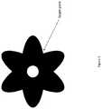
- FIG. 3illustrates a target plate according to certain embodiments of the present invention.
- FIG. 4Aillustrates a top layer of a four-layer PCB according to certain embodiments of the present invention.
- FIG. 4Billustrates a middle layer 1 of the four-layer PCB according to certain embodiments of the present invention.
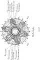
- FIG. 5provides a see-through illustration of the four-layer PCB and a target PCB according to certain embodiments of the present invention.
- FIG. 6Aillustrates a target placed at a 0 degree position, according to certain embodiments of the present invention.
- FIG. 6Billustrates a target placed at a 90 degree position, according to certain embodiments of the present invention.
- FIG. 6Cillustrates a target placed at a 180 degree position, according to certain embodiments of the present invention.
- FIG. 6Dillustrates a target placed at a 270 degree position, according to certain embodiments of the present invention.
- FIG. 7Aillustrates the induced voltage in the first pair of sense coils according to certain embodiments of the present invention.
- FIG. 7Billustrates the induced voltage in the second pair of sense coils according to certain embodiments of the present invention.
- FIG. 8illustrates a method according to certain embodiments of the present invention.
- FIG. 9illustrates a three-dimensional view of a sensing coil according to certain embodiments of the present invention.
- Certain embodiments of the present inventionaddress a dual redundant position sensing mechanism using planar inductive sensing technology. Using this technology, lower angular displacements can be measured with higher accuracy than in many alternative designs.
- This designcan be implemented using two independent sensors each having multiple cycles, without increasing the size and PCB layer count of the device as compared with a single sensing approach (non-redundant).
- the two independent sensorscan include two isolated power supply, oscillator coils, sense coils, and ground paths. If one of these sensors malfunctions, the other can still operate and support the application.
- These sensorscan be inexpensively constructed with stationary printed circuit boards (PCB), coils, and a metal target. A single fault in a PCB component and/or pin level will not cause both sensors to fail.
- PCBprinted circuit boards
- certain embodiments of this designcan better serve safety-critical automotive applications compared to other inductive technology designs.
- certain embodimentscan also compete with other contemporary technologies like Hall effect, capacitive, and optical.
- the design according to certain embodimentscan use emerging planar inductive sensing technology, which may be robust due to the omission of moving electrical contacts, good temperature performance, and resilience to dust.
- These inductive sensing devicescan be used as absolute position sensing devices, which means that they can determine position without moving the target at power-up.
- Certain embodiments of the present inventioninclude a sensor design that incorporates multi-cycle position detection with redundancy without affecting the cost, area, number of PCB layers, and accuracy compared to two independent traditional planar inductive sensors for redundancy. This may be the best fit solution for miniature space and price sensitive applications with high accuracy.
- certain embodimentsmay be particularly suitable to the automotive industry, where safety critical position sensors are required.
- Some of the position sensing applicationsinclude, but are not limited to the brake pedal, throttle body, actuators, and motor control.
- planar inductive position sensormay be cost-effective because coils are laid on PCB.
- certain embodimentscan use two independent sensor coils and integrated circuits (ICs) with the same area taken for a single sensor. If one sensor fails, the other sensor can give feedback information and serve the purpose.
- ICsintegrated circuits
- certain embodimentscan be used for low angular measurement with higher accuracy. This can be achieved by multiple cycle measurement. Moreover, these multiple cycles may also eliminate the need for precise mechanical assembly requirements.
- Inductive sensorscan be used to convert a linear displacement or an angular motion into a proportional electrical signal.
- An inductive sensorcan include two primary coils that sustain the oscillation and two secondary coils that receive position information in the presence of a target.
- High frequency alternating current (AC) carrier signalscan be injected into oscillator coils.
- the respective signals for these circuits, OSC1 and OSC2 signals,can be 180° out of phase to each other.
- the coils for OSC1 and OSC2can be wound in opposite directions geometrically, so the current in both the coils can flow in the same direction, ensuring addition of fields. This generated magnetic field can couple on the sensor coils.
- Each secondary coilcan have two matched segments with current flowing in opposite directions.
- the two segmentscan have the same geometric shape.
- the two segmentscan be laid-out on the PCB in such a way that the flow of current in one segment is in the opposite direction to the other segment.
- the induced voltage in the secondary coilsmay be zero.
- eddy currents in the targetcan cause a difference in sense coil voltages.
- Certain embodiments of the present inventionprovide a 60 mechanical degree design implemented in a four-layer PCB.
- the designcan include two pairs of oscillator coils and sense coils.
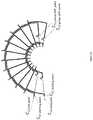
- FIG. 1illustrates two independent pairs of oscillator coils, according to certain embodiments of the present invention.
- the two independent pairs of oscillator coils O 11 , O 12 and O 21 , O 22are shown.
- These oscillatorscan be laid based on an interlaced topology on middle layer 2 and bottom layer of a four-layer PCB.
- the pair of oscillator coilscan be sourced from two independent power supplies, labelled V in1 and V in2 .
- the signals of O 11 and O 12can be 180° out of phase with respect to each other.
- O 21 and O 22can be laid similarly but can be excited from V in2 as shown in FIG. 1 .
- the systemcan also include two pairs of independent sense coils, C 11 , C 12 and C 21 , C 22 , as shown in FIGS. 2A and 2B .
- the two pairs of independent sense coilscan occupy respective upper and lower sides of the reference dotted line shown in FIG. 5 , whereas the oscillator coils can occupy the same area corresponding to both the upper and lower sides.
- the sense coilscan share top and middle layer 1 of the four-layer PCB as shown in FIGS. 4A and 4B respectively.
- FIG. 4Aillustrates a top layer of a four-layer PCB according to certain embodiments of the present invention
- FIG. 4Billustrates a middle layer 1 of the four-layer PCB according to certain embodiments of the present invention.
- FIG. 2Ashows a first pair of sense coils, according to certain embodiments of the present invention.
- C 11 and C 12 sense coilscan be laid at a 90° phase shift with respect to each other. This can be accomplished by laying out the coils with a predetermined mechanical offset of 15°.
- a 360° mechanical rotation of the target platecan produce 6 electrical cycles of sine and cosine, which implies three electrical cycles for 180° rotation.
- the target platecan accordingly be designed with six leaves for a full 360° mechanical rotation of the target and consequently with three leaves for a 180° mechanical rotation of the target (for example, three leaves may be in the upper half of the target and three leaves may be in the lower half of the target, in its initial position).
- the ratio of mechanical rotation to electrical rotationis one mechanical rotation for every six electrical rotations, or 1:6.
- electrically sine and cosineare 90° out of phase to each other. Because there is a 1:6 ratio between mechanical rotation and electrical rotation, a mechanical separation of 1 degree is equivalent to an electrical rotation of 6 degrees.
- 90° of electrical separationif one sense coil is driven with a sine function, then the next separated sense coil will be driven with a cosine function.
- C 11 and C 12can complete three loops on the PCB to reach C 11 , C 12 phase shift points and return to the starting point in an interlaced topology through top and middle layer 1 of the four-layer PCB.
- C 11 and C 12can get terminated at C 11 and C 12 end points and connected to respective ground.
- the phase shift pointsmay simply be the geometric midpoints of the respective sense coils.
- FIG. 9illustrates a three-dimensional view of a sensing coil according to certain embodiments of the present invention.
- a coilcan include a starting half shown in solid line and beginning at the starting point and terminating at the 180 degree phase shift point, and an ending half shown in broken line and beginning at the 180 degree phase shift point and ending at the end point.
- the starting halfcan include three loops 910 , 920 , and 930 , while the ending half can similarly include three loops 940 , 950 , and 960 .
- the starting halfcan provide a forward path for current, while the sending half can provide a return path for current, as illustrated in the lower portion of FIG. 9 .
- FIG. 2Bshows a second pair of sense coils, according to certain embodiments of the present invention.
- C 21 and C 22can be the other two sense coils laid at 90° phase shift with respect to each other.
- C 21 and C 22can complete three cycles to reach C 21 , C 22 phase shift points and can return to the starting point in an interlaced topology through top and middle layer 1 of the 4-layer PCB.
- C 21 and C 22can get terminated at C 21 and C 22 end points and connected to respective ground.
- FIG. 3illustrates a target plate according to certain embodiments of the present invention. This six-leaved shape represents one possible embodiment. In this case, FIG. 3 is drawn to scale, although departures from that scale are permitted.
- FIG. 5provides a see-through illustration of the four-layer PCB and a target, which may be a plate or PCB, according to certain embodiments of the present invention.
- the voltage induced in the sense coils C 11 , C 12 , C 21 , C 22can be read back independently and position information can be calculated based on the independent voltages.
- the target shown in FIG. 3can assist and define the magnetic coupling between the oscillator and sense coils.
- the target shapecan be designed in such a way that when it rotates axially, the magnetic coupling is driven in a sine function.
- the targetcan be a simple metal sheet, copper on PCB, or the like.
- voltages induced in the sense coils C 11 , C 12 and C 21 , C 22are a function of sine and cosine as shown in FIGS. 7 a and 7 b.
- FIG. 7Aillustrates the induced voltage in the first pair of sense coils according to certain embodiments of the present invention
- FIG. 7Billustrates the induced voltage in a second pair of sense coils according to certain embodiments of the present invention.
- FIG. 6Aillustrates a target placed at a 0 degree position, according to certain embodiments of the present invention.
- the 0 degree positionis a reference position of the target, arranged as shown in FIG. 6A .
- the amount of voltage induced in coil C 11 , C 21is shown respectively in FIG. 7A at point a 1 , b 1 .
- the amount of voltage induced in coil C 12 , C 22is shown in FIG. 7B at point c 1 , d 1 .
- FIG. 6Billustrates a target placed at a 90 degree position, according to certain embodiments of the present invention.
- the targetis 90 degrees rotated relative to its initial position shown in FIG. 6A .
- the amount of voltage induced in coil C 11 , C 21is shown in FIG. 7A at point a 2 , b 2 .
- the amount of voltage induced in coil C 12 , C 22is shown in FIG. 7B at point c 2 , d 2 .
- FIG. 6Cillustrates a target placed at a 180 degree position, according to certain embodiments of the present invention.
- the amount of voltage induced in coil C 11 , C 21is shown in FIG. 7A at point a 3 , b 3 .
- the amount of voltage induced in coil C 12 , C 22is shown in FIG. 7B at point c 3 , d 3 .
- FIG. 6Dillustrates a target placed at a 270 degree position, according to certain embodiments of the present invention.
- the amount of voltage induced in coil C 11 , C 21is shown in FIG. 7A at point a 4 , b 4 .
- the amount of voltage induced in coil C 12 , C 22is shown in FIG. 7B at point c 4 , d 4 .
- the electrical cycleends at points a 5 , b 5 , c 5 , d 5 and the next cycle continues, which would be at 360 degrees, which is equivalent to the 0 degrees case mentioned above.
- the targetcompletes total 360° rotation, three electrical cycles can be observed at the output as shown in FIGS. 7A and 7B .
- an apparatuscan include a first planar inductive sensor including two oscillator coils and two sensing coils.
- the apparatuscan also include a second planar inductive sensor independent of the first sensor and also including two oscillator coils and two sensing coils.
- the apparatuscan further include a high frequency alternating current carrier generator configured to inject high frequency alternating current carrier signals into the oscillator coils.
- a carrier signal for the oscillator coil of the first planar inductive sensorcan be 180 degrees out of phase with a carrier signal for the oscillator coil of the same planar inductive sensor.
- the oscillator coil of the first planar inductive sensorcan be wound in an opposite geometric direction from the oscillator coil of the same planar inductive sensor.
- the two sensing coils of the first planar inductive sensorcan be 90 degrees out of phase with one another. Additionally, the two sensing coils of the second planar inductive sensor are 90 degrees out of phase with one another.
- Each of the sense coilscan complete three cycles to reach phase shift points and return to starting point.
- the two oscillator coilscan be sourced from independent power supplies. Eddy currents in a conductive target can cause differences in sense coil voltages.
- the first planar inductive sensorcan be configured to be redundant of the second planar inductive sensor.
- the first planar inductive sensor and the second planar inductive sensorcan be configured such that a single sensor fault that disables one of the sensors will not affect the other sensor.
- a targetcan be provided axially facing the printed circuit board including the oscillating coils and the sensing coils.
- the sensing coilscan be configured to detect the angular position of the target.
- the targetcan be provided on a printed circuit board.
- the sensing coilscan be configured to detect an absolute angular position of the target.
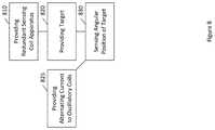
- FIG. 8illustrates a method according to certain embodiments of the present invention.
- the methodcan include providing, at 810 , an apparatus such as described above, having a first planar inductive sensor that includes two oscillator coils and two sensing coils, and also having a second planar inductive sensor independent of the first sensor and also including two oscillator coils and two sensing coils.
- the apparatuscan also have any of the other characteristics described above, such as being constructed on a single four-layer PCB.
- the methodcan further include, at 820 , providing a target electromagnetically linked to each of the sensing coils.
- the methodcan further include, at 830 , sensing an angular position of the target based on voltages induced in the sensing coils.
- the sensed positionmay be an absolute position.
- the methodcan further include, at 825 , providing alternating current as input to the oscillator coils.
Landscapes
- Physics & Mathematics (AREA)
- General Physics & Mathematics (AREA)
- Transmission And Conversion Of Sensor Element Output (AREA)
- Measurement Of Length, Angles, Or The Like Using Electric Or Magnetic Means (AREA)
Abstract
Description
Claims (13)
Priority Applications (3)
| Application Number | Priority Date | Filing Date | Title |
|---|---|---|---|
| PCT/US2018/063681WO2019152092A1 (en) | 2018-02-02 | 2018-12-03 | Multi cycle dual redundant angular position sensing mechanism and associated method of use for precise angular displacement measurement |
| CN201880087041.5ACN111630349B (en) | 2018-02-02 | 2018-12-03 | Multi-cycle dual redundant angular position sensing mechanism for accurate angular displacement measurement and associated method of use |
| DE112018007005.0TDE112018007005B4 (en) | 2018-02-02 | 2018-12-03 | MULTI-CYCLE DOUBLE-REDUNDANT ANGULAR POSITION DETECTING MECHANISM AND RELATED APPLICATION METHOD FOR ACCURATE ANGULAR DISPLACEMENT MEASUREMENT |
Applications Claiming Priority (2)
| Application Number | Priority Date | Filing Date | Title |
|---|---|---|---|
| IN201821004008 | 2018-02-02 | ||
| IN201821004008 | 2018-02-02 |
Publications (2)
| Publication Number | Publication Date |
|---|---|
| US20190242725A1 US20190242725A1 (en) | 2019-08-08 |
| US10921155B2true US10921155B2 (en) | 2021-02-16 |
Family
ID=67476591
Family Applications (1)
| Application Number | Title | Priority Date | Filing Date |
|---|---|---|---|
| US16/205,103Active2039-03-19US10921155B2 (en) | 2018-02-02 | 2018-11-29 | Multi cycle dual redundant angular position sensing mechanism and associated method of use for precise angular displacement measurement |
Country Status (4)
| Country | Link |
|---|---|
| US (1) | US10921155B2 (en) |
| CN (1) | CN111630349B (en) |
| DE (1) | DE112018007005B4 (en) |
| WO (1) | WO2019152092A1 (en) |
Cited By (10)
| Publication number | Priority date | Publication date | Assignee | Title |
|---|---|---|---|---|
| US11150111B2 (en)* | 2016-02-29 | 2021-10-19 | Robert Bosch Gmbh | Rotational angle sensor |
| US20220306192A1 (en)* | 2019-06-27 | 2022-09-29 | Robert Bosch Gmbh | Torque Sensor, Steering Angle Sensor and Corresponding Integrated Sensor and Monitoring System |
| US11598654B2 (en) | 2020-12-14 | 2023-03-07 | Microchip Technology Inc. | High resolution angular inductive sensor and associated method of use |
| US11898887B2 (en) | 2021-03-25 | 2024-02-13 | Microchip Technology Incorporated | Sense coil for inductive rotational-position sensing, and related devices, systems, and methods |
| US20240125586A1 (en)* | 2022-10-17 | 2024-04-18 | Cts Corporation | Reduced offset error configuration for a rotary inductive sensor |
| US12031817B2 (en) | 2021-08-05 | 2024-07-09 | Microchip Technology Incorporated | Inductive angular-position sensors, and related devices, systems, and methods |
| US12111188B2 (en) | 2021-06-11 | 2024-10-08 | Microchip Technology Incorporated | Sense coil for inductive linear-position sensing, and related devices, systems, and methods |
| US12203780B2 (en) | 2022-04-01 | 2025-01-21 | Microchip Technology Incorporated | Target for an inductive angular-position sensor |
| US12339139B2 (en) | 2021-09-28 | 2025-06-24 | Microchip Technology Incorporated | Angular-position sensor |
| US12411001B2 (en) | 2022-04-01 | 2025-09-09 | Microchip Technology Incorporated | Target for inductive angular-position sensing |
Families Citing this family (5)
| Publication number | Priority date | Publication date | Assignee | Title |
|---|---|---|---|---|
| US10921155B2 (en) | 2018-02-02 | 2021-02-16 | Microsemi Corporation | Multi cycle dual redundant angular position sensing mechanism and associated method of use for precise angular displacement measurement |
| US10837847B2 (en) | 2018-10-05 | 2020-11-17 | Microsemi Corporation | Angular rotation sensor |
| US11614765B2 (en)* | 2020-02-14 | 2023-03-28 | Cts Corporation | Vehicle pedal including redundant dual output inductive position sensor with reduced coupling coil circuits |
| US12352607B2 (en) | 2022-06-28 | 2025-07-08 | Allegro Microsystems, Llc | Position sensing method |
| US20250029780A1 (en)* | 2023-07-19 | 2025-01-23 | Allegro Microsystems, Llc | Position sensing method and system |
Citations (52)
| Publication number | Priority date | Publication date | Assignee | Title |
|---|---|---|---|---|
| FR2304900A1 (en) | 1975-03-18 | 1976-10-15 | Metrawatt Gmbh | INDUCTION POSITION INDICATOR |
| US4847548A (en) | 1988-01-28 | 1989-07-11 | General Signal Corporation | Signal conditioner for a linear variable differential transformer |
| US4853604A (en) | 1984-10-19 | 1989-08-01 | Kollmorgen Technologies Corporation | Position and speed sensors |
| US5061896A (en) | 1985-09-03 | 1991-10-29 | United Technologies Corporation | Variable transformer to detect linear displacement with constant output amplitude |
| EP0467514A2 (en) | 1990-07-14 | 1992-01-22 | Lucas Industries Public Limited Company | Temperature compensating circuit for LVDT and control system |
| US5239288A (en) | 1990-03-09 | 1993-08-24 | Transicoil Inc. | Resolver having planar windings |
| US6236199B1 (en) | 1997-09-05 | 2001-05-22 | Hella Kg Hueck & Co. | Inductive angle sensor |
| US6239571B1 (en) | 1999-04-02 | 2001-05-29 | Shiro Shimahara | Resolver |
| US6255810B1 (en) | 1997-09-05 | 2001-07-03 | Hella Kg Hueck & Co. | Inductive angle sensor having coupled oscillators with similar inductive response |
| US6304014B1 (en) | 1997-10-02 | 2001-10-16 | Synaptics (Uk) Limited | Motor control system |
| US6304076B1 (en) | 1999-09-07 | 2001-10-16 | Bei Sensors & Systems Company, Inc. | Angular position sensor with inductive attenuating coupler |
| US20020000129A1 (en) | 1999-09-07 | 2002-01-03 | Madni Asad M. | Non contacting torque sensor |
| DE10120822A1 (en) | 2000-09-20 | 2002-04-04 | Balluff Gmbh | Inductive displacement sensor with linear characteristic has voltage induced in variable geometry measuring loop compared with voltage in constant geometry reference loop |
| US6384598B1 (en) | 1999-09-01 | 2002-05-07 | Hella Kg Hueck & Co. | Inductive position sensor having multiple receiving geometries |
| US20020097042A1 (en) | 2001-01-24 | 2002-07-25 | Texas Instruments Incorporated | Non-contact position sensor and method |
| US6522128B1 (en) | 1997-10-15 | 2003-02-18 | Synaptics (Uk) Limited | Position sensor having compact arrangement of coils |
| US6593730B2 (en) | 2000-02-01 | 2003-07-15 | Cherry Gmbh | Position sensor |
| US6605940B1 (en) | 2000-04-12 | 2003-08-12 | Kavlico Corporation | Linear variable differential transformer assembly with nulling adjustment and process for nulling adjustment |
| US20030206007A1 (en) | 2002-05-02 | 2003-11-06 | Balluff Gmbh | Inductive displacement sensor with a measuring head comprising a passive resonant circuit |
| US20040081313A1 (en) | 2002-06-21 | 2004-04-29 | Disney Enterprises, Inc. | System and method for wirelessly transmitting and receiving digital tokens for use in electronic gameplay |
| US20040080313A1 (en) | 2001-10-03 | 2004-04-29 | Amnon Brosh | Modular non-contacting position sensor |
| JP3839449B2 (en) | 2004-09-28 | 2006-11-01 | 誠 成瀬 | Position detection device |
| US20070001666A1 (en) | 2005-06-27 | 2007-01-04 | Lee Joong K | Linear and rotational inductive position sensor |
| US7276897B2 (en) | 2004-04-09 | 2007-10-02 | Ksr International Co. | Inductive position sensor |
| EP1914520A2 (en) | 2006-10-11 | 2008-04-23 | Hitachi, Ltd. | Inductive rotation angle sensor and motor-driven airflow control device using the same |
| US20080164869A1 (en) | 2005-03-07 | 2008-07-10 | Sappel | Inductive Angular-Position Sensor |
| US20080174302A1 (en) | 2007-01-19 | 2008-07-24 | Ksr Technologies Co. | Inductive position sensor using reference signal |
| US20080238416A1 (en) | 2007-04-02 | 2008-10-02 | Shozoh Shiraga | Rotation angle detector |
| WO2008125853A1 (en) | 2007-04-17 | 2008-10-23 | Penny & Giles Controls Limited | Inductive sensors |
| US20090079422A1 (en) | 2007-09-21 | 2009-03-26 | Ksr Technologies Co. | Inductive position sensor |
| EP2145158A2 (en) | 2007-05-10 | 2010-01-20 | Cambridge Integrated Circuits Limited | Transducer |
| EP2044389B1 (en) | 2005-01-28 | 2010-04-07 | Mark Anthony Howard | Inductive displacement detector |
| US7726208B2 (en) | 2006-11-22 | 2010-06-01 | Zf Friedrichshafen Ag | Combined steering angle and torque sensor |
| US20100271012A1 (en)* | 2009-04-28 | 2010-10-28 | Patterson William R | Electromagnetic position and orientation sensing system |
| US20110101968A1 (en)* | 2008-03-26 | 2011-05-05 | Elmos Semiconductor Ag | Inductive position sensor |
| US20120081106A1 (en)* | 2010-09-30 | 2012-04-05 | Rockwell Automation Technologies, Inc. | Double-coil inductive proximity sensor apparatus |
| US20120175198A1 (en)* | 2011-01-10 | 2012-07-12 | Messier-Bugatti-Dowty | Electromechanical actuator with dual excitation |
| US20120242352A1 (en)* | 2011-02-22 | 2012-09-27 | Rockwell Automation Asia Pacific Business Center Pte. Ltd. | Inductive proximity sensor |
| US8508242B2 (en) | 2010-01-25 | 2013-08-13 | Ksr Technologies Co. | Inductive position sensor |
| US20130289826A1 (en) | 2012-04-26 | 2013-10-31 | Hitachi Automotive Systems Steering, Ltd. | Power Steering Apparatus, and Controller for Power Steering Apparatus |
| US8947077B2 (en) | 2011-05-19 | 2015-02-03 | Ksr Ip Holdings Llc. | Rotary position sensor |
| US8988066B2 (en) | 2011-03-02 | 2015-03-24 | Ksr Ip Holdings Llc | Steering position and torque sensor |
| US20160214648A1 (en) | 2012-12-13 | 2016-07-28 | Valeo Schalter Und Sensoren Gmbh | Device with a torque sensor device and a steering angle sensor device for a motor vehicle, motor vehicle and method for manufacturing a device |
| US9528858B2 (en)* | 2012-11-13 | 2016-12-27 | Semiconductor Components Industries, Llc | Inductive sensor |
| US20170158231A1 (en) | 2014-06-25 | 2017-06-08 | Trw Limited | An Electric Power Assisted Steering System |
| US9677913B2 (en) | 2014-04-28 | 2017-06-13 | Microsemi Corporation | Inductive displacement sensor |
| WO2017100515A1 (en) | 2015-12-10 | 2017-06-15 | Ksr Ip Holdings Llc. | Inductive steering torque and angle sensor |
| WO2018108783A2 (en) | 2016-12-12 | 2018-06-21 | Idt Europe Gmbh | Ultra-thin combined inductive torque and angle sensor for steering wheel position sensing |
| US20190063956A1 (en)* | 2017-08-22 | 2019-02-28 | Semiconductor Components Industries, Llc | Inductive Position Sensor |
| US20190226828A1 (en)* | 2018-01-22 | 2019-07-25 | Melexis Technologies Sa | Inductive position sensor |
| WO2019152092A1 (en) | 2018-02-02 | 2019-08-08 | Microsemi Corporation | Multi cycle dual redundant angular position sensing mechanism and associated method of use for precise angular displacement measurement |
| US10415952B2 (en) | 2016-10-28 | 2019-09-17 | Microsemi Corporation | Angular position sensor and associated method of use |
Family Cites Families (2)
| Publication number | Priority date | Publication date | Assignee | Title |
|---|---|---|---|---|
| GB0126014D0 (en)* | 2001-10-30 | 2001-12-19 | Sensopad Technologies Ltd | Modulated field position sensor |
| FR2893409B1 (en)* | 2005-11-15 | 2008-05-02 | Moving Magnet Tech | MAGNETIC ANGULAR POSITION SENSOR FOR A RACE OF UP TO 360 ° |
- 2018
- 2018-11-29USUS16/205,103patent/US10921155B2/enactiveActive
- 2018-12-03CNCN201880087041.5Apatent/CN111630349B/enactiveActive
- 2018-12-03WOPCT/US2018/063681patent/WO2019152092A1/ennot_activeCeased
- 2018-12-03DEDE112018007005.0Tpatent/DE112018007005B4/enactiveActive
Patent Citations (58)
| Publication number | Priority date | Publication date | Assignee | Title |
|---|---|---|---|---|
| FR2304900A1 (en) | 1975-03-18 | 1976-10-15 | Metrawatt Gmbh | INDUCTION POSITION INDICATOR |
| US4853604A (en) | 1984-10-19 | 1989-08-01 | Kollmorgen Technologies Corporation | Position and speed sensors |
| US5061896A (en) | 1985-09-03 | 1991-10-29 | United Technologies Corporation | Variable transformer to detect linear displacement with constant output amplitude |
| US4847548A (en) | 1988-01-28 | 1989-07-11 | General Signal Corporation | Signal conditioner for a linear variable differential transformer |
| US5239288A (en) | 1990-03-09 | 1993-08-24 | Transicoil Inc. | Resolver having planar windings |
| EP0467514A2 (en) | 1990-07-14 | 1992-01-22 | Lucas Industries Public Limited Company | Temperature compensating circuit for LVDT and control system |
| US6255810B1 (en) | 1997-09-05 | 2001-07-03 | Hella Kg Hueck & Co. | Inductive angle sensor having coupled oscillators with similar inductive response |
| US6236199B1 (en) | 1997-09-05 | 2001-05-22 | Hella Kg Hueck & Co. | Inductive angle sensor |
| US6304014B1 (en) | 1997-10-02 | 2001-10-16 | Synaptics (Uk) Limited | Motor control system |
| US6522128B1 (en) | 1997-10-15 | 2003-02-18 | Synaptics (Uk) Limited | Position sensor having compact arrangement of coils |
| US6239571B1 (en) | 1999-04-02 | 2001-05-29 | Shiro Shimahara | Resolver |
| US6384598B1 (en) | 1999-09-01 | 2002-05-07 | Hella Kg Hueck & Co. | Inductive position sensor having multiple receiving geometries |
| US6304076B1 (en) | 1999-09-07 | 2001-10-16 | Bei Sensors & Systems Company, Inc. | Angular position sensor with inductive attenuating coupler |
| US20020000129A1 (en) | 1999-09-07 | 2002-01-03 | Madni Asad M. | Non contacting torque sensor |
| US6593730B2 (en) | 2000-02-01 | 2003-07-15 | Cherry Gmbh | Position sensor |
| US6605940B1 (en) | 2000-04-12 | 2003-08-12 | Kavlico Corporation | Linear variable differential transformer assembly with nulling adjustment and process for nulling adjustment |
| DE10120822A1 (en) | 2000-09-20 | 2002-04-04 | Balluff Gmbh | Inductive displacement sensor with linear characteristic has voltage induced in variable geometry measuring loop compared with voltage in constant geometry reference loop |
| US20020097042A1 (en) | 2001-01-24 | 2002-07-25 | Texas Instruments Incorporated | Non-contact position sensor and method |
| US20040080313A1 (en) | 2001-10-03 | 2004-04-29 | Amnon Brosh | Modular non-contacting position sensor |
| US20030206007A1 (en) | 2002-05-02 | 2003-11-06 | Balluff Gmbh | Inductive displacement sensor with a measuring head comprising a passive resonant circuit |
| US20040081313A1 (en) | 2002-06-21 | 2004-04-29 | Disney Enterprises, Inc. | System and method for wirelessly transmitting and receiving digital tokens for use in electronic gameplay |
| US7276897B2 (en) | 2004-04-09 | 2007-10-02 | Ksr International Co. | Inductive position sensor |
| JP3839449B2 (en) | 2004-09-28 | 2006-11-01 | 誠 成瀬 | Position detection device |
| EP2044389B1 (en) | 2005-01-28 | 2010-04-07 | Mark Anthony Howard | Inductive displacement detector |
| US20080164869A1 (en) | 2005-03-07 | 2008-07-10 | Sappel | Inductive Angular-Position Sensor |
| US20070001666A1 (en) | 2005-06-27 | 2007-01-04 | Lee Joong K | Linear and rotational inductive position sensor |
| US7821256B2 (en) | 2005-06-27 | 2010-10-26 | Ksr Technologies Co. | Linear and rotational inductive position sensor |
| EP1914520A2 (en) | 2006-10-11 | 2008-04-23 | Hitachi, Ltd. | Inductive rotation angle sensor and motor-driven airflow control device using the same |
| US7726208B2 (en) | 2006-11-22 | 2010-06-01 | Zf Friedrichshafen Ag | Combined steering angle and torque sensor |
| US20080174302A1 (en) | 2007-01-19 | 2008-07-24 | Ksr Technologies Co. | Inductive position sensor using reference signal |
| US20080238416A1 (en) | 2007-04-02 | 2008-10-02 | Shozoh Shiraga | Rotation angle detector |
| WO2008125853A1 (en) | 2007-04-17 | 2008-10-23 | Penny & Giles Controls Limited | Inductive sensors |
| EP2145158A2 (en) | 2007-05-10 | 2010-01-20 | Cambridge Integrated Circuits Limited | Transducer |
| US20090079422A1 (en) | 2007-09-21 | 2009-03-26 | Ksr Technologies Co. | Inductive position sensor |
| US7906960B2 (en) | 2007-09-21 | 2011-03-15 | Ksr Technologies Co. | Inductive position sensor |
| US20110101968A1 (en)* | 2008-03-26 | 2011-05-05 | Elmos Semiconductor Ag | Inductive position sensor |
| US20100271012A1 (en)* | 2009-04-28 | 2010-10-28 | Patterson William R | Electromagnetic position and orientation sensing system |
| US8508242B2 (en) | 2010-01-25 | 2013-08-13 | Ksr Technologies Co. | Inductive position sensor |
| US8618791B2 (en)* | 2010-09-30 | 2013-12-31 | Rockwell Automation Technologies, Inc. | Double-coil inductive proximity sensor apparatus |
| US20120081106A1 (en)* | 2010-09-30 | 2012-04-05 | Rockwell Automation Technologies, Inc. | Double-coil inductive proximity sensor apparatus |
| US20120175198A1 (en)* | 2011-01-10 | 2012-07-12 | Messier-Bugatti-Dowty | Electromechanical actuator with dual excitation |
| US20120242352A1 (en)* | 2011-02-22 | 2012-09-27 | Rockwell Automation Asia Pacific Business Center Pte. Ltd. | Inductive proximity sensor |
| US8988066B2 (en) | 2011-03-02 | 2015-03-24 | Ksr Ip Holdings Llc | Steering position and torque sensor |
| US8947077B2 (en) | 2011-05-19 | 2015-02-03 | Ksr Ip Holdings Llc. | Rotary position sensor |
| US20130289826A1 (en) | 2012-04-26 | 2013-10-31 | Hitachi Automotive Systems Steering, Ltd. | Power Steering Apparatus, and Controller for Power Steering Apparatus |
| US9528858B2 (en)* | 2012-11-13 | 2016-12-27 | Semiconductor Components Industries, Llc | Inductive sensor |
| US20160214648A1 (en) | 2012-12-13 | 2016-07-28 | Valeo Schalter Und Sensoren Gmbh | Device with a torque sensor device and a steering angle sensor device for a motor vehicle, motor vehicle and method for manufacturing a device |
| US9677913B2 (en) | 2014-04-28 | 2017-06-13 | Microsemi Corporation | Inductive displacement sensor |
| US20170158231A1 (en) | 2014-06-25 | 2017-06-08 | Trw Limited | An Electric Power Assisted Steering System |
| WO2017100515A1 (en) | 2015-12-10 | 2017-06-15 | Ksr Ip Holdings Llc. | Inductive steering torque and angle sensor |
| US20170166251A1 (en) | 2015-12-10 | 2017-06-15 | Ksr Ip Holdings Llc | Inductive steering torque and angle sensor |
| US10415952B2 (en) | 2016-10-28 | 2019-09-17 | Microsemi Corporation | Angular position sensor and associated method of use |
| WO2018108783A2 (en) | 2016-12-12 | 2018-06-21 | Idt Europe Gmbh | Ultra-thin combined inductive torque and angle sensor for steering wheel position sensing |
| US20190331541A1 (en) | 2016-12-12 | 2019-10-31 | Integrated Device Technology, Inc. | Ultra-thin combined inductive torque and angle sensor for steering wheel position sensing |
| US20190063956A1 (en)* | 2017-08-22 | 2019-02-28 | Semiconductor Components Industries, Llc | Inductive Position Sensor |
| US20190226828A1 (en)* | 2018-01-22 | 2019-07-25 | Melexis Technologies Sa | Inductive position sensor |
| WO2019152092A1 (en) | 2018-02-02 | 2019-08-08 | Microsemi Corporation | Multi cycle dual redundant angular position sensing mechanism and associated method of use for precise angular displacement measurement |
| US20190242725A1 (en) | 2018-02-02 | 2019-08-08 | Microsemi Corporation | Multi cycle dual redundant angular position sensing mechanism and associated method of use for precise angular displacement measurement |
Non-Patent Citations (5)
| Title |
|---|
| "A Revolution in Sensing: World's First Inductance-to-Digital Converter", Texas Instruments, 2013, pp. 1-6. |
| International Search Report and Written Opinion, PCT/US2018/063681, dated Mar. 8, 2019. |
| PCT/US2019/042895, International Search Report, dated Oct. 21, 2019. |
| PCT/US2019/042895, Written Opinion of the International Search Authority, dated Oct. 21, 2019. |
| U.S. Appl. No. 16/152,802, filed Oct. 2018, Kevin Mark Smith, Jr. |
Cited By (12)
| Publication number | Priority date | Publication date | Assignee | Title |
|---|---|---|---|---|
| US11150111B2 (en)* | 2016-02-29 | 2021-10-19 | Robert Bosch Gmbh | Rotational angle sensor |
| US20220306192A1 (en)* | 2019-06-27 | 2022-09-29 | Robert Bosch Gmbh | Torque Sensor, Steering Angle Sensor and Corresponding Integrated Sensor and Monitoring System |
| US12134434B2 (en)* | 2019-06-27 | 2024-11-05 | Robert Bosch Gmbh | Torque sensor, steering angle sensor and corresponding integrated sensor and monitoring system |
| US11598654B2 (en) | 2020-12-14 | 2023-03-07 | Microchip Technology Inc. | High resolution angular inductive sensor and associated method of use |
| US11898887B2 (en) | 2021-03-25 | 2024-02-13 | Microchip Technology Incorporated | Sense coil for inductive rotational-position sensing, and related devices, systems, and methods |
| US12111188B2 (en) | 2021-06-11 | 2024-10-08 | Microchip Technology Incorporated | Sense coil for inductive linear-position sensing, and related devices, systems, and methods |
| US12031817B2 (en) | 2021-08-05 | 2024-07-09 | Microchip Technology Incorporated | Inductive angular-position sensors, and related devices, systems, and methods |
| US12339139B2 (en) | 2021-09-28 | 2025-06-24 | Microchip Technology Incorporated | Angular-position sensor |
| US12203780B2 (en) | 2022-04-01 | 2025-01-21 | Microchip Technology Incorporated | Target for an inductive angular-position sensor |
| US12411001B2 (en) | 2022-04-01 | 2025-09-09 | Microchip Technology Incorporated | Target for inductive angular-position sensing |
| US20240125586A1 (en)* | 2022-10-17 | 2024-04-18 | Cts Corporation | Reduced offset error configuration for a rotary inductive sensor |
| US12320638B2 (en)* | 2022-10-17 | 2025-06-03 | Cts Corporation | Reduced offset error configuration for a rotary inductive sensor |
Also Published As
| Publication number | Publication date |
|---|---|
| DE112018007005T5 (en) | 2020-10-29 |
| CN111630349B (en) | 2022-07-01 |
| WO2019152092A1 (en) | 2019-08-08 |
| DE112018007005B4 (en) | 2023-07-20 |
| CN111630349A (en) | 2020-09-04 |
| US20190242725A1 (en) | 2019-08-08 |
Similar Documents
| Publication | Publication Date | Title |
|---|---|---|
| US10921155B2 (en) | Multi cycle dual redundant angular position sensing mechanism and associated method of use for precise angular displacement measurement | |
| US9945653B2 (en) | Inductive position sensor | |
| US10415952B2 (en) | Angular position sensor and associated method of use | |
| JP7300320B2 (en) | Receiving line spacing in electromagnetic induction encoder | |
| US7190158B2 (en) | Inductive angle-of-rotation sensor and rotary transducer equipped with the same | |
| US8020453B2 (en) | Inductive position sensor | |
| CN110657826B (en) | Scale structure for inductive position encoder | |
| US11656101B2 (en) | Redundant angular position sensor and associated method of use | |
| RU2432549C2 (en) | Method and instrument for contactless detection of absolute position and device equipped with this instrument | |
| US9383184B2 (en) | Inductive position-measuring device | |
| EP1122520A1 (en) | Position sensor | |
| EP1828722B1 (en) | Inductive position sensor | |
| US11598654B2 (en) | High resolution angular inductive sensor and associated method of use | |
| US11221236B1 (en) | Angular position sensor and associated method of use | |
| CN116136420A (en) | Radial inductive position sensor, high resolution position sensor system and torque sensor system for detecting rotational movement | |
| US7196527B2 (en) | Redundant compact encoders | |
| WO2022132229A1 (en) | High resolution angular inductive sensor and associated method of use | |
| EP4053509B1 (en) | Target and receiver for an inductive sensor | |
| US11664714B2 (en) | Position sensor assembly, position-determining method, and linear actuator | |
| CN109564111A (en) | It is designed to the inductive position sensor of the Angle Position of measurement axis or the like | |
| US20240426593A1 (en) | Inductive angle measuring device | |
| US8829925B2 (en) | Capacitive position sensor | |
| CN119665788A (en) | Inductive position determination system and position determination method with changing coil shape |
Legal Events
| Date | Code | Title | Description |
|---|---|---|---|
| AS | Assignment | Owner name:MICROSEMI CORPORATION, CALIFORNIA Free format text:ASSIGNMENT OF ASSIGNORS INTEREST;ASSIGNORS:SHAGA, GANESH;NAUDURI, BALA SUNDARAM;REEL/FRAME:047629/0654 Effective date:20180308 | |
| FEPP | Fee payment procedure | Free format text:ENTITY STATUS SET TO UNDISCOUNTED (ORIGINAL EVENT CODE: BIG.); ENTITY STATUS OF PATENT OWNER: LARGE ENTITY | |
| AS | Assignment | Owner name:JPMORGAN CHASE BANK, N.A., AS ADMINISTRATIVE AGENT, DELAWARE Free format text:SECURITY INTEREST;ASSIGNORS:MICROCHIP TECHNOLOGY INC.;SILICON STORAGE TECHNOLOGY, INC.;ATMEL CORPORATION;AND OTHERS;REEL/FRAME:053311/0305 Effective date:20200327 | |
| AS | Assignment | Owner name:ATMEL CORPORATION, ARIZONA Free format text:RELEASE BY SECURED PARTY;ASSIGNOR:JPMORGAN CHASE BANK, N.A, AS ADMINISTRATIVE AGENT;REEL/FRAME:053466/0011 Effective date:20200529 Owner name:MICROSEMI STORAGE SOLUTIONS, INC., ARIZONA Free format text:RELEASE BY SECURED PARTY;ASSIGNOR:JPMORGAN CHASE BANK, N.A, AS ADMINISTRATIVE AGENT;REEL/FRAME:053466/0011 Effective date:20200529 Owner name:MICROSEMI CORPORATION, CALIFORNIA Free format text:RELEASE BY SECURED PARTY;ASSIGNOR:JPMORGAN CHASE BANK, N.A, AS ADMINISTRATIVE AGENT;REEL/FRAME:053466/0011 Effective date:20200529 Owner name:SILICON STORAGE TECHNOLOGY, INC., ARIZONA Free format text:RELEASE BY SECURED PARTY;ASSIGNOR:JPMORGAN CHASE BANK, N.A, AS ADMINISTRATIVE AGENT;REEL/FRAME:053466/0011 Effective date:20200529 Owner name:MICROCHIP TECHNOLOGY INC., ARIZONA Free format text:RELEASE BY SECURED PARTY;ASSIGNOR:JPMORGAN CHASE BANK, N.A, AS ADMINISTRATIVE AGENT;REEL/FRAME:053466/0011 Effective date:20200529 | |
| STPP | Information on status: patent application and granting procedure in general | Free format text:NON FINAL ACTION MAILED | |
| AS | Assignment | Owner name:JPMORGAN CHASE BANK, N.A., AS ADMINISTRATIVE AGENT, ILLINOIS Free format text:SECURITY INTEREST;ASSIGNORS:MICROCHIP TECHNOLOGY INC.;SILICON STORAGE TECHNOLOGY, INC.;ATMEL CORPORATION;AND OTHERS;REEL/FRAME:052856/0909 Effective date:20200529 Owner name:WELLS FARGO BANK, NATIONAL ASSOCIATION, MINNESOTA Free format text:SECURITY INTEREST;ASSIGNORS:MICROCHIP TECHNOLOGY INC.;SILICON STORAGE TECHNOLOGY, INC.;ATMEL CORPORATION;AND OTHERS;REEL/FRAME:053468/0705 Effective date:20200529 | |
| STPP | Information on status: patent application and granting procedure in general | Free format text:RESPONSE TO NON-FINAL OFFICE ACTION ENTERED AND FORWARDED TO EXAMINER | |
| AS | Assignment | Owner name:WELLS FARGO BANK, NATIONAL ASSOCIATION, AS COLLATERAL AGENT, MINNESOTA Free format text:SECURITY INTEREST;ASSIGNORS:MICROCHIP TECHNOLOGY INCORPORATED;SILICON STORAGE TECHNOLOGY, INC.;ATMEL CORPORATION;AND OTHERS;REEL/FRAME:055671/0612 Effective date:20201217 | |
| STPP | Information on status: patent application and granting procedure in general | Free format text:NOTICE OF ALLOWANCE MAILED -- APPLICATION RECEIVED IN OFFICE OF PUBLICATIONS | |
| STCF | Information on status: patent grant | Free format text:PATENTED CASE | |
| AS | Assignment | Owner name:WELLS FARGO BANK, NATIONAL ASSOCIATION, AS NOTES COLLATERAL AGENT, MINNESOTA Free format text:SECURITY INTEREST;ASSIGNORS:MICROCHIP TECHNOLOGY INCORPORATED;SILICON STORAGE TECHNOLOGY, INC.;ATMEL CORPORATION;AND OTHERS;REEL/FRAME:057935/0474 Effective date:20210528 | |
| AS | Assignment | Owner name:WELLS FARGO BANK, NATIONAL ASSOCIATION, AS NOTES COLLATERAL AGENT, MINNESOTA Free format text:GRANT OF SECURITY INTEREST IN PATENT RIGHTS;ASSIGNORS:MICROCHIP TECHNOLOGY INCORPORATED;SILICON STORAGE TECHNOLOGY, INC.;ATMEL CORPORATION;AND OTHERS;REEL/FRAME:058214/0625 Effective date:20211117 | |
| AS | Assignment | Owner name:MICROSEMI STORAGE SOLUTIONS, INC., ARIZONA Free format text:RELEASE BY SECURED PARTY;ASSIGNOR:JPMORGAN CHASE BANK, N.A., AS ADMINISTRATIVE AGENT;REEL/FRAME:059263/0001 Effective date:20220218 Owner name:MICROSEMI CORPORATION, ARIZONA Free format text:RELEASE BY SECURED PARTY;ASSIGNOR:JPMORGAN CHASE BANK, N.A., AS ADMINISTRATIVE AGENT;REEL/FRAME:059263/0001 Effective date:20220218 Owner name:ATMEL CORPORATION, ARIZONA Free format text:RELEASE BY SECURED PARTY;ASSIGNOR:JPMORGAN CHASE BANK, N.A., AS ADMINISTRATIVE AGENT;REEL/FRAME:059263/0001 Effective date:20220218 Owner name:SILICON STORAGE TECHNOLOGY, INC., ARIZONA Free format text:RELEASE BY SECURED PARTY;ASSIGNOR:JPMORGAN CHASE BANK, N.A., AS ADMINISTRATIVE AGENT;REEL/FRAME:059263/0001 Effective date:20220218 Owner name:MICROCHIP TECHNOLOGY INCORPORATED, ARIZONA Free format text:RELEASE BY SECURED PARTY;ASSIGNOR:JPMORGAN CHASE BANK, N.A., AS ADMINISTRATIVE AGENT;REEL/FRAME:059263/0001 Effective date:20220218 | |
| AS | Assignment | Owner name:MICROSEMI STORAGE SOLUTIONS, INC., ARIZONA Free format text:RELEASE BY SECURED PARTY;ASSIGNOR:WELLS FARGO BANK, NATIONAL ASSOCIATION, AS NOTES COLLATERAL AGENT;REEL/FRAME:059358/0335 Effective date:20220228 Owner name:MICROSEMI CORPORATION, ARIZONA Free format text:RELEASE BY SECURED PARTY;ASSIGNOR:WELLS FARGO BANK, NATIONAL ASSOCIATION, AS NOTES COLLATERAL AGENT;REEL/FRAME:059358/0335 Effective date:20220228 Owner name:ATMEL CORPORATION, ARIZONA Free format text:RELEASE BY SECURED PARTY;ASSIGNOR:WELLS FARGO BANK, NATIONAL ASSOCIATION, AS NOTES COLLATERAL AGENT;REEL/FRAME:059358/0335 Effective date:20220228 Owner name:SILICON STORAGE TECHNOLOGY, INC., ARIZONA Free format text:RELEASE BY SECURED PARTY;ASSIGNOR:WELLS FARGO BANK, NATIONAL ASSOCIATION, AS NOTES COLLATERAL AGENT;REEL/FRAME:059358/0335 Effective date:20220228 Owner name:MICROCHIP TECHNOLOGY INCORPORATED, ARIZONA Free format text:RELEASE BY SECURED PARTY;ASSIGNOR:WELLS FARGO BANK, NATIONAL ASSOCIATION, AS NOTES COLLATERAL AGENT;REEL/FRAME:059358/0335 Effective date:20220228 | |
| AS | Assignment | Owner name:MICROSEMI STORAGE SOLUTIONS, INC., ARIZONA Free format text:RELEASE BY SECURED PARTY;ASSIGNOR:WELLS FARGO BANK, NATIONAL ASSOCIATION, AS NOTES COLLATERAL AGENT;REEL/FRAME:059863/0400 Effective date:20220228 Owner name:MICROSEMI CORPORATION, ARIZONA Free format text:RELEASE BY SECURED PARTY;ASSIGNOR:WELLS FARGO BANK, NATIONAL ASSOCIATION, AS NOTES COLLATERAL AGENT;REEL/FRAME:059863/0400 Effective date:20220228 Owner name:ATMEL CORPORATION, ARIZONA Free format text:RELEASE BY SECURED PARTY;ASSIGNOR:WELLS FARGO BANK, NATIONAL ASSOCIATION, AS NOTES COLLATERAL AGENT;REEL/FRAME:059863/0400 Effective date:20220228 Owner name:SILICON STORAGE TECHNOLOGY, INC., ARIZONA Free format text:RELEASE BY SECURED PARTY;ASSIGNOR:WELLS FARGO BANK, NATIONAL ASSOCIATION, AS NOTES COLLATERAL AGENT;REEL/FRAME:059863/0400 Effective date:20220228 Owner name:MICROCHIP TECHNOLOGY INCORPORATED, ARIZONA Free format text:RELEASE BY SECURED PARTY;ASSIGNOR:WELLS FARGO BANK, NATIONAL ASSOCIATION, AS NOTES COLLATERAL AGENT;REEL/FRAME:059863/0400 Effective date:20220228 | |
| AS | Assignment | Owner name:MICROSEMI STORAGE SOLUTIONS, INC., ARIZONA Free format text:RELEASE BY SECURED PARTY;ASSIGNOR:WELLS FARGO BANK, NATIONAL ASSOCIATION, AS NOTES COLLATERAL AGENT;REEL/FRAME:060894/0437 Effective date:20220228 Owner name:MICROSEMI CORPORATION, ARIZONA Free format text:RELEASE BY SECURED PARTY;ASSIGNOR:WELLS FARGO BANK, NATIONAL ASSOCIATION, AS NOTES COLLATERAL AGENT;REEL/FRAME:060894/0437 Effective date:20220228 Owner name:ATMEL CORPORATION, ARIZONA Free format text:RELEASE BY SECURED PARTY;ASSIGNOR:WELLS FARGO BANK, NATIONAL ASSOCIATION, AS NOTES COLLATERAL AGENT;REEL/FRAME:060894/0437 Effective date:20220228 Owner name:SILICON STORAGE TECHNOLOGY, INC., ARIZONA Free format text:RELEASE BY SECURED PARTY;ASSIGNOR:WELLS FARGO BANK, NATIONAL ASSOCIATION, AS NOTES COLLATERAL AGENT;REEL/FRAME:060894/0437 Effective date:20220228 Owner name:MICROCHIP TECHNOLOGY INCORPORATED, ARIZONA Free format text:RELEASE BY SECURED PARTY;ASSIGNOR:WELLS FARGO BANK, NATIONAL ASSOCIATION, AS NOTES COLLATERAL AGENT;REEL/FRAME:060894/0437 Effective date:20220228 | |
| MAFP | Maintenance fee payment | Free format text:PAYMENT OF MAINTENANCE FEE, 4TH YEAR, LARGE ENTITY (ORIGINAL EVENT CODE: M1551); ENTITY STATUS OF PATENT OWNER: LARGE ENTITY Year of fee payment:4 |