US10920716B2 - Hybrid vehicle - Google Patents
Hybrid vehicleDownload PDFInfo
- Publication number
- US10920716B2 US10920716B2US16/675,969US201916675969AUS10920716B2US 10920716 B2US10920716 B2US 10920716B2US 201916675969 AUS201916675969 AUS 201916675969AUS 10920716 B2US10920716 B2US 10920716B2
- Authority
- US
- United States
- Prior art keywords
- casing
- vaporized gas
- engine
- control valve
- side wall
- Prior art date
- Legal status (The legal status is an assumption and is not a legal conclusion. Google has not performed a legal analysis and makes no representation as to the accuracy of the status listed.)
- Expired - Fee Related
Links
Images


Classifications
- F—MECHANICAL ENGINEERING; LIGHTING; HEATING; WEAPONS; BLASTING
- F02—COMBUSTION ENGINES; HOT-GAS OR COMBUSTION-PRODUCT ENGINE PLANTS
- F02M—SUPPLYING COMBUSTION ENGINES IN GENERAL WITH COMBUSTIBLE MIXTURES OR CONSTITUENTS THEREOF
- F02M25/00—Engine-pertinent apparatus for adding non-fuel substances or small quantities of secondary fuel to combustion-air, main fuel or fuel-air mixture
- F02M25/08—Engine-pertinent apparatus for adding non-fuel substances or small quantities of secondary fuel to combustion-air, main fuel or fuel-air mixture adding fuel vapours drawn from engine fuel reservoir
- F02M25/089—Layout of the fuel vapour installation
- B—PERFORMING OPERATIONS; TRANSPORTING
- B60—VEHICLES IN GENERAL
- B60K—ARRANGEMENT OR MOUNTING OF PROPULSION UNITS OR OF TRANSMISSIONS IN VEHICLES; ARRANGEMENT OR MOUNTING OF PLURAL DIVERSE PRIME-MOVERS IN VEHICLES; AUXILIARY DRIVES FOR VEHICLES; INSTRUMENTATION OR DASHBOARDS FOR VEHICLES; ARRANGEMENTS IN CONNECTION WITH COOLING, AIR INTAKE, GAS EXHAUST OR FUEL SUPPLY OF PROPULSION UNITS IN VEHICLES
- B60K6/00—Arrangement or mounting of plural diverse prime-movers for mutual or common propulsion, e.g. hybrid propulsion systems comprising electric motors and internal combustion engines
- B60K6/20—Arrangement or mounting of plural diverse prime-movers for mutual or common propulsion, e.g. hybrid propulsion systems comprising electric motors and internal combustion engines the prime-movers consisting of electric motors and internal combustion engines, e.g. HEVs
- B60K6/22—Arrangement or mounting of plural diverse prime-movers for mutual or common propulsion, e.g. hybrid propulsion systems comprising electric motors and internal combustion engines the prime-movers consisting of electric motors and internal combustion engines, e.g. HEVs characterised by apparatus, components or means specially adapted for HEVs
- B60K6/40—Arrangement or mounting of plural diverse prime-movers for mutual or common propulsion, e.g. hybrid propulsion systems comprising electric motors and internal combustion engines the prime-movers consisting of electric motors and internal combustion engines, e.g. HEVs characterised by apparatus, components or means specially adapted for HEVs characterised by the assembly or relative disposition of components
- B—PERFORMING OPERATIONS; TRANSPORTING
- B60—VEHICLES IN GENERAL
- B60K—ARRANGEMENT OR MOUNTING OF PROPULSION UNITS OR OF TRANSMISSIONS IN VEHICLES; ARRANGEMENT OR MOUNTING OF PLURAL DIVERSE PRIME-MOVERS IN VEHICLES; AUXILIARY DRIVES FOR VEHICLES; INSTRUMENTATION OR DASHBOARDS FOR VEHICLES; ARRANGEMENTS IN CONNECTION WITH COOLING, AIR INTAKE, GAS EXHAUST OR FUEL SUPPLY OF PROPULSION UNITS IN VEHICLES
- B60K15/00—Arrangement in connection with fuel supply of combustion engines or other fuel consuming energy converters, e.g. fuel cells; Mounting or construction of fuel tanks
- B60K15/03—Fuel tanks
- B60K15/035—Fuel tanks characterised by venting means
- B60K15/03519—Valve arrangements in the vent line
- B—PERFORMING OPERATIONS; TRANSPORTING
- B60—VEHICLES IN GENERAL
- B60K—ARRANGEMENT OR MOUNTING OF PROPULSION UNITS OR OF TRANSMISSIONS IN VEHICLES; ARRANGEMENT OR MOUNTING OF PLURAL DIVERSE PRIME-MOVERS IN VEHICLES; AUXILIARY DRIVES FOR VEHICLES; INSTRUMENTATION OR DASHBOARDS FOR VEHICLES; ARRANGEMENTS IN CONNECTION WITH COOLING, AIR INTAKE, GAS EXHAUST OR FUEL SUPPLY OF PROPULSION UNITS IN VEHICLES
- B60K15/00—Arrangement in connection with fuel supply of combustion engines or other fuel consuming energy converters, e.g. fuel cells; Mounting or construction of fuel tanks
- B60K15/03—Fuel tanks
- B60K15/063—Arrangement of tanks
- B—PERFORMING OPERATIONS; TRANSPORTING
- B60—VEHICLES IN GENERAL
- B60K—ARRANGEMENT OR MOUNTING OF PROPULSION UNITS OR OF TRANSMISSIONS IN VEHICLES; ARRANGEMENT OR MOUNTING OF PLURAL DIVERSE PRIME-MOVERS IN VEHICLES; AUXILIARY DRIVES FOR VEHICLES; INSTRUMENTATION OR DASHBOARDS FOR VEHICLES; ARRANGEMENTS IN CONNECTION WITH COOLING, AIR INTAKE, GAS EXHAUST OR FUEL SUPPLY OF PROPULSION UNITS IN VEHICLES
- B60K6/00—Arrangement or mounting of plural diverse prime-movers for mutual or common propulsion, e.g. hybrid propulsion systems comprising electric motors and internal combustion engines
- B60K6/20—Arrangement or mounting of plural diverse prime-movers for mutual or common propulsion, e.g. hybrid propulsion systems comprising electric motors and internal combustion engines the prime-movers consisting of electric motors and internal combustion engines, e.g. HEVs
- B60K6/22—Arrangement or mounting of plural diverse prime-movers for mutual or common propulsion, e.g. hybrid propulsion systems comprising electric motors and internal combustion engines the prime-movers consisting of electric motors and internal combustion engines, e.g. HEVs characterised by apparatus, components or means specially adapted for HEVs
- B60K6/40—Arrangement or mounting of plural diverse prime-movers for mutual or common propulsion, e.g. hybrid propulsion systems comprising electric motors and internal combustion engines the prime-movers consisting of electric motors and internal combustion engines, e.g. HEVs characterised by apparatus, components or means specially adapted for HEVs characterised by the assembly or relative disposition of components
- B60K6/405—Housings
- B—PERFORMING OPERATIONS; TRANSPORTING
- B60—VEHICLES IN GENERAL
- B60W—CONJOINT CONTROL OF VEHICLE SUB-UNITS OF DIFFERENT TYPE OR DIFFERENT FUNCTION; CONTROL SYSTEMS SPECIALLY ADAPTED FOR HYBRID VEHICLES; ROAD VEHICLE DRIVE CONTROL SYSTEMS FOR PURPOSES NOT RELATED TO THE CONTROL OF A PARTICULAR SUB-UNIT
- B60W20/00—Control systems specially adapted for hybrid vehicles
- B60W20/10—Controlling the power contribution of each of the prime movers to meet required power demand
- B60W20/15—Control strategies specially adapted for achieving a particular effect
- F—MECHANICAL ENGINEERING; LIGHTING; HEATING; WEAPONS; BLASTING
- F02—COMBUSTION ENGINES; HOT-GAS OR COMBUSTION-PRODUCT ENGINE PLANTS
- F02M—SUPPLYING COMBUSTION ENGINES IN GENERAL WITH COMBUSTIBLE MIXTURES OR CONSTITUENTS THEREOF
- F02M25/00—Engine-pertinent apparatus for adding non-fuel substances or small quantities of secondary fuel to combustion-air, main fuel or fuel-air mixture
- F02M25/08—Engine-pertinent apparatus for adding non-fuel substances or small quantities of secondary fuel to combustion-air, main fuel or fuel-air mixture adding fuel vapours drawn from engine fuel reservoir
- F02M25/0836—Arrangement of valves controlling the admission of fuel vapour to an engine, e.g. valve being disposed between fuel tank or absorption canister and intake manifold
- Y—GENERAL TAGGING OF NEW TECHNOLOGICAL DEVELOPMENTS; GENERAL TAGGING OF CROSS-SECTIONAL TECHNOLOGIES SPANNING OVER SEVERAL SECTIONS OF THE IPC; TECHNICAL SUBJECTS COVERED BY FORMER USPC CROSS-REFERENCE ART COLLECTIONS [XRACs] AND DIGESTS
- Y02—TECHNOLOGIES OR APPLICATIONS FOR MITIGATION OR ADAPTATION AGAINST CLIMATE CHANGE
- Y02T—CLIMATE CHANGE MITIGATION TECHNOLOGIES RELATED TO TRANSPORTATION
- Y02T10/00—Road transport of goods or passengers
- Y02T10/60—Other road transportation technologies with climate change mitigation effect
- Y02T10/62—Hybrid vehicles
Definitions
- the present disclosurerelates to a structure of a hybrid vehicle, and more particularly to a structure within an engine compartment in a front portion of a vehicle.
- fuelis vaporized to generate fuel-vaporized gas.
- the fuel-vaporized gasis suctioned to a canister.
- the fuel-vaporized gasis released from the canister and introduced through a purge pipe into an intake manifold of the engine, where the fuel-vaporized gas is burned.
- the purge pipeincludes a vaporized gas control valve for adjusting an amount of the fuel-vaporized gas to be introduced into the engine.
- the vaporized gas control valveis often disposed within an engine compartment in the front portion of a vehicle.
- a structure including a vaporized gas control valve behind the enginehas been suggested (see JP 2011-84088 A, for example).
- the vaporized gas control valve, which is associated with the enginemay be disposed near the engine.
- a hybrid vehicleIn recent years, hybrid vehicles that are driven by an engine and a motor are widely in use.
- a hybrid vehicleoften includes a power control unit that controls a hybrid system within an engine compartment in the front portion of the vehicle.
- the power control unitmay be damaged by the vaporized gas control valve in a collision, depending on the position of the vaporized gas control valve.
- An embodiment of the disclosureis therefore directed toward reducing damage of a power control unit caused by a vaporized gas control valve in a collision in a hybrid vehicle.
- a hybrid vehicle of the disclosureincludes an engine compartment located in a front portion of the vehicle.
- the engine compartmentincludes a power control unit configured to control an engine and a motor, and a vaporized gas control valve.
- the vaporized gas control valveis disposed on a purge pipe that introduces fuel-vaporized gas generated in a fuel tank into the engine, to adjust flow of the fuel-vaporized gas.
- the power control unitis stored within a casing, and the vaporized gas control valve is disposed on a top portion of a side wall of the casing.
- the side walls of the casinghave greater strength along the height of the vehicle than other portions of the casing. Therefore, even when the hood covering the top surface of the engine compartment interferes with the vaporized gas control valve in a collision to cause application of a collision load to the side wall of the casing, the casing having such strength reduces damage to the power control unit stored in the casing.
- the enginemay be adjacent to the casing storing the power control unit along a width of the vehicle in the engine compartment and may be disposed such that a top surface of the engine is located higher than a top surface of the casing.
- the vaporized gas control valvemay be disposed on a top portion of the side wall of the casing closer to the engine.
- This arrangementallows the vaporized gas control valve to be disposed in a space formed by the hood, the engine, and the casing, to thereby prevent the vaporized gas control valve from being depressed directly by the hood in a frontal crash.
- This structurereduces damage to the power control unit by the vaporized gas control valve in a frontal crash.
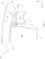
- FIG. 1is a plan view of an engine compartment of a hybrid vehicle according to an embodiment
- FIG. 2is an elevation of the engine compartment of the hybrid vehicle according to the embodiment
- FIG. 3is a plan view illustrating barrier intrusion in a head-on crash and barrier intrusion in a small overlap frontal crash of the hybrid vehicle illustrated in FIG. 1 ;
- FIG. 4is an elevation illustrating downward movement of a hood in a frontal crash of the hybrid vehicle illustrated in FIG. 1 .
- an arrow FR, an arrow UP, and an arrow RHindicate the forward direction (traveling direction), the upward direction, and the rightward direction of a vehicle, respectively.
- Directions opposite to these arrows FR, UP, and RHindicate the rearward direction, the downward direction, and the leftward direction of the vehicle, respectively.
- forward and rearward, leftward and rightward, and upward and downwardrefer to forward and rearward along the length of a vehicle, leftward and rightward along the width of the vehicle, and upward and downward along the height of the vehicle, respectively.
- the hybrid vehicle 100 of the embodimentincludes an engine compartment 10 in a front portion thereof.
- the engine compartment 10houses an engine 11 and a motor 12 , a power control unit 13 stored in a casing 20 , and a vaporized gas control valve 15 .
- a hood 30covers the upper side of the engine compartment.
- the casing 20 storing the power control unit 13is a box shape member having opposite side walls 21 and 22 along the width of the vehicle, opposite side walls 23 and 24 along the length of the vehicle, and a bottom plate 26 and a top plate 25 .
- the side walls 21 to 24have a greater strength along the height of the vehicle than other portions of the casing.
- the top plate 25has a top surface which forms a top surface 20 U of the casing 20 .
- the engine 11is adjacent to the casing 20 along the width of the vehicle, and is disposed such that a top surface 11 U of the engine 11 is located higher than the top surface 20 U of the casing 20 .
- the power control unit 13controls the engine 11 and the motor 12 , and includes a high-voltage component.
- the vaporized gas control valve 15is disposed on a purge pipe 14 that introduces fuel-vaporized gas generated in a fuel tank into an intake manifold 11 a of the engine 11 , to adjust flow of the fuel-vaporized gas.
- the vaporized gas control valve 15is attached, via a bracket 16 , to the top portion of the side wall 21 of the casing 20 closer to the engine 11 toward the front.
- the vaporized gas control valve 15is raised above the casing 20 by the bracket 16 .
- the bracket 16has a base portion fixed to the side wall 21 of the casing 20 .
- the vaporized gas control valve 15which is disposed as described above, is not sandwiched between a barrier 91 and the casing 20 of the power control unit 13 , as illustrated in FIG. 3 .
- This structureprevents the casing 20 or the power control unit 13 from being damaged by the vaporized gas control valve 15 having high rigidity.
- the vaporized gas control valve 15is not sandwiched between a barrier 92 and the casing 20 of the power control unit 13 , as illustrated in FIG. 3 , which also prevents the casing 20 or the power control unit 13 from being damaged by the vaporized gas control valve 15 having high rigidity.
- the vaporized gas control valve 15is disposed within a space 50 formed by the hood 30 , the engine 11 , and the casing 20 , as indicated by a dashed line in FIG. 4 . It is therefore possible to prevent the hood 30 from interfering with the vaporized gas control valve 15 and depressing the vaporized gas control valve 15 directly downward upon collision. This structure further reduces damage to the power control unit 13 caused by the vaporized gas control valve 15 in a frontal crash.
- the hybrid vehicle 100can reduce damage to the power control unit 13 caused by the vaporized gas control valve 15 in a collision.
- the vaporized gas control valve 15is attached, via the bracket 16 , to the side wall 21 of the casing 20 closer to the engine 11 toward the front at the top portion of the side wall 21 , the disclosure is not limited to this embodiment.
- the vaporized gas control valve 15may be attached to top portion of the side wall 21 of the casing 20 toward the rear or may be attached to the top of the side wall 21 in the center portion in the vehicle length direction.
Landscapes
- Engineering & Computer Science (AREA)
- Mechanical Engineering (AREA)
- Chemical & Material Sciences (AREA)
- Combustion & Propulsion (AREA)
- Transportation (AREA)
- General Engineering & Computer Science (AREA)
- Sustainable Energy (AREA)
- Life Sciences & Earth Sciences (AREA)
- Sustainable Development (AREA)
- Automation & Control Theory (AREA)
- Hybrid Electric Vehicles (AREA)
- Supplying Secondary Fuel Or The Like To Fuel, Air Or Fuel-Air Mixtures (AREA)
- Cooling, Air Intake And Gas Exhaust, And Fuel Tank Arrangements In Propulsion Units (AREA)
- Arrangement Or Mounting Of Propulsion Units For Vehicles (AREA)
Abstract
Description
Claims (11)
Applications Claiming Priority (2)
| Application Number | Priority Date | Filing Date | Title |
|---|---|---|---|
| JP2018246892AJP7056547B2 (en) | 2018-12-28 | 2018-12-28 | Hybrid vehicle |
| JP2018-246892 | 2018-12-28 |
Publications (2)
| Publication Number | Publication Date |
|---|---|
| US20200208593A1 US20200208593A1 (en) | 2020-07-02 |
| US10920716B2true US10920716B2 (en) | 2021-02-16 |
Family
ID=71122193
Family Applications (1)
| Application Number | Title | Priority Date | Filing Date |
|---|---|---|---|
| US16/675,969Expired - Fee RelatedUS10920716B2 (en) | 2018-12-28 | 2019-11-06 | Hybrid vehicle |
Country Status (3)
| Country | Link |
|---|---|
| US (1) | US10920716B2 (en) |
| JP (1) | JP7056547B2 (en) |
| CN (1) | CN111376704B (en) |
Citations (4)
| Publication number | Priority date | Publication date | Assignee | Title |
|---|---|---|---|---|
| JP2011084088A (en) | 2009-10-13 | 2011-04-28 | Suzuki Motor Corp | Piping device of canister |
| US20110308501A1 (en)* | 2010-06-17 | 2011-12-22 | Toyota Jidosha Kabushiki Kaisha | Internal combustion engine control apparatus and control method for internal combustion engine control apparatus |
| US20150047350A1 (en)* | 2013-08-19 | 2015-02-19 | Ford Global Technologies, Llc | System and method for operating an engine combusting liquefied petroleum gas |
| US9512791B1 (en)* | 2015-06-23 | 2016-12-06 | Ford Global Technologies, Llc | Systems and methods for operating an evaporative emissions system |
Family Cites Families (15)
| Publication number | Priority date | Publication date | Assignee | Title |
|---|---|---|---|---|
| JP3139599B2 (en)* | 1994-11-10 | 2001-03-05 | 本田技研工業株式会社 | Canister arrangement structure |
| FR2736592A1 (en)* | 1995-07-12 | 1997-01-17 | Walbro Corp | FUEL FILLING AND VAPOR RETENTION APPARATUS FOR A FUEL TANK OF A VEHICLE |
| KR20090006911A (en)* | 2007-07-13 | 2009-01-16 | 현대자동차주식회사 | Arrangement structure of LP cylinder for hybrid vehicle and integrated battery |
| JP2009121353A (en)* | 2007-11-15 | 2009-06-04 | Toyota Motor Corp | Fuel vapor treatment method and fuel vapor treatment apparatus |
| JP4319239B2 (en)* | 2008-02-07 | 2009-08-26 | 本田技研工業株式会社 | Hybrid vehicle |
| EP2402197B1 (en)* | 2009-02-24 | 2013-10-02 | Toyota Jidosha Kabushiki Kaisha | Vehicle front structure |
| JP2010270618A (en)* | 2009-05-19 | 2010-12-02 | Toyota Motor Corp | Evaporative fuel processing equipment |
| JP5929435B2 (en)* | 2012-04-04 | 2016-06-08 | スズキ株式会社 | Hybrid vehicle power unit |
| WO2014192376A1 (en)* | 2013-05-31 | 2014-12-04 | アイシン・エィ・ダブリュ株式会社 | Vehicle driving apparatus |
| JP6222444B2 (en)* | 2013-10-31 | 2017-11-01 | スズキ株式会社 | Vehicle front structure |
| DE102015117194B4 (en)* | 2014-11-13 | 2021-10-14 | Toyota Jidosha Kabushiki Kaisha | Vehicle with fuel cells mounted on it and control procedures for the vehicle |
| JP6610876B2 (en)* | 2015-11-11 | 2019-11-27 | 三菱自動車エンジニアリング株式会社 | Vehicle equipped with transpiration fuel processing equipment |
| JP6536596B2 (en)* | 2017-01-19 | 2019-07-03 | トヨタ自動車株式会社 | On-board structure of power control device |
| JP6800790B2 (en)* | 2017-03-21 | 2020-12-16 | 愛三工業株式会社 | Vehicle fuel cell system |
| JP6436179B2 (en)* | 2017-03-22 | 2018-12-12 | マツダ株式会社 | engine |
- 2018
- 2018-12-28JPJP2018246892Apatent/JP7056547B2/enactiveActive
- 2019
- 2019-11-06USUS16/675,969patent/US10920716B2/ennot_activeExpired - Fee Related
- 2019-11-14CNCN201911111971.2Apatent/CN111376704B/enactiveActive
Patent Citations (4)
| Publication number | Priority date | Publication date | Assignee | Title |
|---|---|---|---|---|
| JP2011084088A (en) | 2009-10-13 | 2011-04-28 | Suzuki Motor Corp | Piping device of canister |
| US20110308501A1 (en)* | 2010-06-17 | 2011-12-22 | Toyota Jidosha Kabushiki Kaisha | Internal combustion engine control apparatus and control method for internal combustion engine control apparatus |
| US20150047350A1 (en)* | 2013-08-19 | 2015-02-19 | Ford Global Technologies, Llc | System and method for operating an engine combusting liquefied petroleum gas |
| US9512791B1 (en)* | 2015-06-23 | 2016-12-06 | Ford Global Technologies, Llc | Systems and methods for operating an evaporative emissions system |
Non-Patent Citations (2)
| Title |
|---|
| JPH0932671-Feb. 1997, Butsuchi et al., machine translation.* |
| JPH0932671—Feb. 1997, Butsuchi et al., machine translation.* |
Also Published As
| Publication number | Publication date |
|---|---|
| CN111376704A (en) | 2020-07-07 |
| CN111376704B (en) | 2023-02-21 |
| JP2020104770A (en) | 2020-07-09 |
| US20200208593A1 (en) | 2020-07-02 |
| JP7056547B2 (en) | 2022-04-19 |
Similar Documents
| Publication | Publication Date | Title |
|---|---|---|
| JP2013112210A (en) | Battery mounting structure of vehicle | |
| US10040413B2 (en) | Vehicle | |
| JP2009057031A (en) | Chassis frame for fuel cell vehicle | |
| US11097786B2 (en) | Vehicle front structure | |
| JP2013155666A (en) | Fuel supply device for vehicular engine | |
| US11312233B2 (en) | Shift bracket | |
| US11142057B2 (en) | Drive unit | |
| JP2007326446A (en) | Exhaust system | |
| US10920716B2 (en) | Hybrid vehicle | |
| JP2019001231A (en) | Lower body structure | |
| CN102555953B (en) | Collision reaction structure of automobile | |
| US9975579B2 (en) | Cowl structure | |
| US20180245551A1 (en) | Intake pipe supporting structure | |
| JP4359835B2 (en) | Canister mounting structure | |
| JP6315059B1 (en) | Vehicle tank structure | |
| CN102166955B (en) | Fuel filter mounting structure of vehicle | |
| JP2016084023A (en) | vehicle | |
| JP2006224874A (en) | Fuel cell vehicle component arrangement structure | |
| CN109693714B (en) | front structure of the vehicle | |
| JP7683336B2 (en) | Vehicle fuel cell system | |
| JP7632130B2 (en) | Engine side structure | |
| US20240300462A1 (en) | Vehicle brake apparatus | |
| JP2019111977A (en) | Vehicle structure | |
| CN110206662B (en) | Vehicle lower structure | |
| JP6315060B1 (en) | Vehicle tank structure |
Legal Events
| Date | Code | Title | Description |
|---|---|---|---|
| FEPP | Fee payment procedure | Free format text:ENTITY STATUS SET TO UNDISCOUNTED (ORIGINAL EVENT CODE: BIG.); ENTITY STATUS OF PATENT OWNER: LARGE ENTITY | |
| AS | Assignment | Owner name:TOYOTA JIDOSHA KABUSHIKI KAISHA, JAPAN Free format text:ASSIGNMENT OF ASSIGNORS INTEREST;ASSIGNOR:KAMBAYASHI, TAKU;REEL/FRAME:050957/0687 Effective date:20190911 | |
| STPP | Information on status: patent application and granting procedure in general | Free format text:NON FINAL ACTION MAILED | |
| STPP | Information on status: patent application and granting procedure in general | Free format text:RESPONSE TO NON-FINAL OFFICE ACTION ENTERED AND FORWARDED TO EXAMINER | |
| STCF | Information on status: patent grant | Free format text:PATENTED CASE | |
| FEPP | Fee payment procedure | Free format text:MAINTENANCE FEE REMINDER MAILED (ORIGINAL EVENT CODE: REM.); ENTITY STATUS OF PATENT OWNER: LARGE ENTITY | |
| LAPS | Lapse for failure to pay maintenance fees | Free format text:PATENT EXPIRED FOR FAILURE TO PAY MAINTENANCE FEES (ORIGINAL EVENT CODE: EXP.); ENTITY STATUS OF PATENT OWNER: LARGE ENTITY | |
| STCH | Information on status: patent discontinuation | Free format text:PATENT EXPIRED DUE TO NONPAYMENT OF MAINTENANCE FEES UNDER 37 CFR 1.362 | |
| FP | Lapsed due to failure to pay maintenance fee | Effective date:20250216 |