US10919106B2 - Ultrasonic welding of annular components - Google Patents
Ultrasonic welding of annular componentsDownload PDFInfo
- Publication number
- US10919106B2 US10919106B2US15/618,282US201715618282AUS10919106B2US 10919106 B2US10919106 B2US 10919106B2US 201715618282 AUS201715618282 AUS 201715618282AUS 10919106 B2US10919106 B2US 10919106B2
- Authority
- US
- United States
- Prior art keywords
- layers
- forming
- feedstock
- group
- sheet
- Prior art date
- Legal status (The legal status is an assumption and is not a legal conclusion. Google has not performed a legal analysis and makes no representation as to the accuracy of the status listed.)
- Active, expires
Links
Images


Classifications
- B—PERFORMING OPERATIONS; TRANSPORTING
- B23—MACHINE TOOLS; METAL-WORKING NOT OTHERWISE PROVIDED FOR
- B23K—SOLDERING OR UNSOLDERING; WELDING; CLADDING OR PLATING BY SOLDERING OR WELDING; CUTTING BY APPLYING HEAT LOCALLY, e.g. FLAME CUTTING; WORKING BY LASER BEAM
- B23K20/00—Non-electric welding by applying impact or other pressure, with or without the application of heat, e.g. cladding or plating
- B23K20/10—Non-electric welding by applying impact or other pressure, with or without the application of heat, e.g. cladding or plating making use of vibrations, e.g. ultrasonic welding
- B23K20/103—Non-electric welding by applying impact or other pressure, with or without the application of heat, e.g. cladding or plating making use of vibrations, e.g. ultrasonic welding using a roller
- B—PERFORMING OPERATIONS; TRANSPORTING
- B23—MACHINE TOOLS; METAL-WORKING NOT OTHERWISE PROVIDED FOR
- B23K—SOLDERING OR UNSOLDERING; WELDING; CLADDING OR PLATING BY SOLDERING OR WELDING; CUTTING BY APPLYING HEAT LOCALLY, e.g. FLAME CUTTING; WORKING BY LASER BEAM
- B23K20/00—Non-electric welding by applying impact or other pressure, with or without the application of heat, e.g. cladding or plating
- B23K20/10—Non-electric welding by applying impact or other pressure, with or without the application of heat, e.g. cladding or plating making use of vibrations, e.g. ultrasonic welding
- B—PERFORMING OPERATIONS; TRANSPORTING
- B21—MECHANICAL METAL-WORKING WITHOUT ESSENTIALLY REMOVING MATERIAL; PUNCHING METAL
- B21C—MANUFACTURE OF METAL SHEETS, WIRE, RODS, TUBES, PROFILES OR LIKE SEMI-MANUFACTURED PRODUCTS OTHERWISE THAN BY ROLLING; AUXILIARY OPERATIONS USED IN CONNECTION WITH METAL-WORKING WITHOUT ESSENTIALLY REMOVING MATERIAL
- B21C37/00—Manufacture of metal sheets, rods, wire, tubes, profiles or like semi-manufactured products, not otherwise provided for; Manufacture of tubes of special shape
- B21C37/06—Manufacture of metal sheets, rods, wire, tubes, profiles or like semi-manufactured products, not otherwise provided for; Manufacture of tubes of special shape of tubes or metal hoses; Combined procedures for making tubes, e.g. for making multi-wall tubes
- B21C37/08—Making tubes with welded or soldered seams
- B21C37/09—Making tubes with welded or soldered seams of coated strip material ; Making multi-wall tubes
- B—PERFORMING OPERATIONS; TRANSPORTING
- B21—MECHANICAL METAL-WORKING WITHOUT ESSENTIALLY REMOVING MATERIAL; PUNCHING METAL
- B21C—MANUFACTURE OF METAL SHEETS, WIRE, RODS, TUBES, PROFILES OR LIKE SEMI-MANUFACTURED PRODUCTS OTHERWISE THAN BY ROLLING; AUXILIARY OPERATIONS USED IN CONNECTION WITH METAL-WORKING WITHOUT ESSENTIALLY REMOVING MATERIAL
- B21C37/00—Manufacture of metal sheets, rods, wire, tubes, profiles or like semi-manufactured products, not otherwise provided for; Manufacture of tubes of special shape
- B21C37/06—Manufacture of metal sheets, rods, wire, tubes, profiles or like semi-manufactured products, not otherwise provided for; Manufacture of tubes of special shape of tubes or metal hoses; Combined procedures for making tubes, e.g. for making multi-wall tubes
- B21C37/12—Making tubes or metal hoses with helically arranged seams
- B21C37/122—Making tubes or metal hoses with helically arranged seams with welded or soldered seams
- B—PERFORMING OPERATIONS; TRANSPORTING
- B21—MECHANICAL METAL-WORKING WITHOUT ESSENTIALLY REMOVING MATERIAL; PUNCHING METAL
- B21C—MANUFACTURE OF METAL SHEETS, WIRE, RODS, TUBES, PROFILES OR LIKE SEMI-MANUFACTURED PRODUCTS OTHERWISE THAN BY ROLLING; AUXILIARY OPERATIONS USED IN CONNECTION WITH METAL-WORKING WITHOUT ESSENTIALLY REMOVING MATERIAL
- B21C37/00—Manufacture of metal sheets, rods, wire, tubes, profiles or like semi-manufactured products, not otherwise provided for; Manufacture of tubes of special shape
- B21C37/06—Manufacture of metal sheets, rods, wire, tubes, profiles or like semi-manufactured products, not otherwise provided for; Manufacture of tubes of special shape of tubes or metal hoses; Combined procedures for making tubes, e.g. for making multi-wall tubes
- B21C37/12—Making tubes or metal hoses with helically arranged seams
- B21C37/123—Making tubes or metal hoses with helically arranged seams of coated strip material; Making multi-wall tubes
- B—PERFORMING OPERATIONS; TRANSPORTING
- B21—MECHANICAL METAL-WORKING WITHOUT ESSENTIALLY REMOVING MATERIAL; PUNCHING METAL
- B21C—MANUFACTURE OF METAL SHEETS, WIRE, RODS, TUBES, PROFILES OR LIKE SEMI-MANUFACTURED PRODUCTS OTHERWISE THAN BY ROLLING; AUXILIARY OPERATIONS USED IN CONNECTION WITH METAL-WORKING WITHOUT ESSENTIALLY REMOVING MATERIAL
- B21C37/00—Manufacture of metal sheets, rods, wire, tubes, profiles or like semi-manufactured products, not otherwise provided for; Manufacture of tubes of special shape
- B21C37/06—Manufacture of metal sheets, rods, wire, tubes, profiles or like semi-manufactured products, not otherwise provided for; Manufacture of tubes of special shape of tubes or metal hoses; Combined procedures for making tubes, e.g. for making multi-wall tubes
- B21C37/15—Making tubes of special shape; Making tube fittings
- B21C37/154—Making multi-wall tubes
- B—PERFORMING OPERATIONS; TRANSPORTING
- B23—MACHINE TOOLS; METAL-WORKING NOT OTHERWISE PROVIDED FOR
- B23K—SOLDERING OR UNSOLDERING; WELDING; CLADDING OR PLATING BY SOLDERING OR WELDING; CUTTING BY APPLYING HEAT LOCALLY, e.g. FLAME CUTTING; WORKING BY LASER BEAM
- B23K20/00—Non-electric welding by applying impact or other pressure, with or without the application of heat, e.g. cladding or plating
- B23K20/16—Non-electric welding by applying impact or other pressure, with or without the application of heat, e.g. cladding or plating with interposition of special material to facilitate connection of the parts, e.g. material for absorbing or producing gas
- B—PERFORMING OPERATIONS; TRANSPORTING
- B23—MACHINE TOOLS; METAL-WORKING NOT OTHERWISE PROVIDED FOR
- B23K—SOLDERING OR UNSOLDERING; WELDING; CLADDING OR PLATING BY SOLDERING OR WELDING; CUTTING BY APPLYING HEAT LOCALLY, e.g. FLAME CUTTING; WORKING BY LASER BEAM
- B23K20/00—Non-electric welding by applying impact or other pressure, with or without the application of heat, e.g. cladding or plating
- B23K20/24—Preliminary treatment
- B—PERFORMING OPERATIONS; TRANSPORTING
- B23—MACHINE TOOLS; METAL-WORKING NOT OTHERWISE PROVIDED FOR
- B23K—SOLDERING OR UNSOLDERING; WELDING; CLADDING OR PLATING BY SOLDERING OR WELDING; CUTTING BY APPLYING HEAT LOCALLY, e.g. FLAME CUTTING; WORKING BY LASER BEAM
- B23K20/00—Non-electric welding by applying impact or other pressure, with or without the application of heat, e.g. cladding or plating
- B23K20/26—Auxiliary equipment
- B—PERFORMING OPERATIONS; TRANSPORTING
- B23—MACHINE TOOLS; METAL-WORKING NOT OTHERWISE PROVIDED FOR
- B23K—SOLDERING OR UNSOLDERING; WELDING; CLADDING OR PLATING BY SOLDERING OR WELDING; CUTTING BY APPLYING HEAT LOCALLY, e.g. FLAME CUTTING; WORKING BY LASER BEAM
- B23K2101/00—Articles made by soldering, welding or cutting
- B23K2101/001—Turbines
Definitions
- This inventionrelates generally to component manufacturing, and more particularly to apparatus and methods for manufacturing large shell-type structures.
- Numerous productsincorporate structures or components which have an annular shape in the form of a cylinder, cone, or partial cylinder.
- An examplewould be a cylindrical casing for a gas turbine engine.
- ultrasonic weldinguses an “ultrasonic horn” which is a thin blade or rib tool powered by a piezoelectric transducer and actuated at its resonant frequency to put ultrasonic energy into the workpiece. This does generate heat but it is not fusion welding; rather it is a solid-state bond.
- a method of making an annular componentincludes: forming sheet feedstock into an annular shape disposed about a central axis; and bonding one portion of the feedstock to another portion of the feedstock using ultrasonic welding, so as to fix the annular shape.
- a method of making an annular turbine engine componentincludes: forming sheet metal feedstock into an annular shape; bonding one portion of feedstock to another portion of the feedstock using ultrasonic welding; repeating the steps of forming and bonding the feedstock to create a plurality of concentric layers; and forming bonds between the layers using ultrasonic welding.
- FIG. 1is a schematic, end view of an exemplary ultrasonic welding apparatus
- FIG. 2is a schematic side view of an ultrasonic welding head of the apparatus shown in FIG. 1 ;
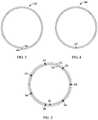
- FIG. 3is a schematic end view showing a first step of a component forming process using the apparatus of FIG. 1 ;
- FIG. 4is a schematic end view showing a second step of the component forming process shown in FIG. 3 ;
- FIG. 5is a schematic end view showing a third step of the component forming process shown in FIG. 3 ;
- FIG. 6is a schematic end view showing an alternative component forming process using the apparatus of FIG. 1 ;
- FIG. 7is a schematic end view of an exemplary multi-layer structure manufactured using the apparatus of FIG. 1 ;
- FIG. 8is a side elevation view of the structure shown in FIG. 7 ;
- FIG. 9is a schematic end view of another exemplary multi-layer structure manufactured using the apparatus of FIG. 1 ;
- FIG. 10is a side elevation view of the structure shown in FIG. 9 ;
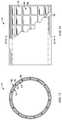
- FIG. 11is a schematic, partially-broken-away side elevation view of another exemplary multi-layer structure manufactured using the apparatus of FIG. 1 ;
- FIG. 12is a view taken along lines 12 - 12 of FIG. 11 .
- FIG. 1illustrates schematically a welding and forming apparatus 10 suitable for carrying out a combined ultrasonic welding and forming operation.
- Basic components of the apparatus 10include an ultrasonic welding head 12 , a workpiece support 14 , and a plurality of forming elements 16 , all arrayed about a central axis 18 . Each of these components will be described in more detail below.
- the ultrasonic welding head 12comprises a probe or “ultrasonic horn” 20 which is configured, in accordance with known techniques, to be actuated at its resonant frequency to transfer ultrasonic energy into a workpiece that the probe 20 is contacting, resulting in workpiece heating and creation of a solid-state bond.
- the probe 20has a small width “W”, for example about 1 mm (0.04 inches), and an overall length “L” as required to suit a particular application, for example several centimeters (inches). The length (i.e.
- the longest dimension) of the probe 20is oriented parallel to the central axis 18 of the apparatus 10 and appropriate actuator or adjustment device 22 may be provided to move the ultrasonic welding head 12 in the radial direction relative to the central axis 18 (i.e. towards or away from the workpiece).
- the probe 20is mechanically coupled to a driver 24 (shown schematically) configured to vibrate the probe 20 at one of its resonant frequencies.
- a driver 24shown schematically
- One example of a known type of driveris a piezoelectric transducer.
- the driver 24may be coupled to an appropriate electrical power supply 26 .
- the workpiece support 14includes a surface positioned facing the probe 20 and configured to be pressed against a workpiece in opposition to the probe 20 , in order to provide support and prevent deflection of the workpiece.
- the workpiece support 14comprises a cylindrical roller.
- An appropriate actuator or adjustment device 28may be provided to move the backside pressure device in the radial direction and/or adjust the pressure applied to the workpiece.
- the forming elements 16include one or more surfaces positioned and configured to apply pressure to a workpiece causing it to form in a curved shape as it is fed into the apparatus 10 .
- the forming elements 16include a plurality of cylindrical rollers arrayed in appropriate locations around the central axis 18 .
- An appropriate actuator or adjustment device 30may be provided to move the forming elements 16 in the radial direction and/or adjust the pressure applied to the workpiece. Additional actuators or mechanical elements (not shown) may be provided to move the forming elements 16 through one or more forming motions (sliding, moving in an arc, etc.) in accordance with conventional practice for sheet metal bending processes.
- Each supply roll 32contains a supply of feedstock 34 , in the form of sheet material wound about a central mandrel.
- the feedstock 34may be any material which capable of being bonded using ultrasonic welding and which is also capable of being formed into a curved or annular shape without fracturing (e.g. a material which is ductile rather than brittle).
- a suitable feedstock materialis a metal alloy in sheet form. The thickness of the feedstock is limited by the depth of penetration of the ultrasonic welding process. As one example, the metal alloy sheet may be about 0.5 mm (0.010 inches) thick or less.
- the apparatus 10may include a feed mechanism configured to pull material from the supply rolls 32 and feed it into the apparatus 10 .
- the feed mechanismcomprises a pair of opposed feed rollers 38 which engage in clamp the feedstock 34 from opposite faces.
- the feed rollers 38may be driven, for example, by one or more electric motors (not shown).
- the operation of the apparatus 10 described above including the welding head 12 , workpiece support 14 , forming elements 16 , and feeding mechanismmay be controlled, for example, by software running on one or more processors embodied in one or more devices such as a programmable logic controller (“PLC”) or a microcomputer (shown schematically at 40 ).
- processorsmay be coupled to various sensors and operating components, for example, through wired or wireless connections.
- the same processor or processorsmay be used to retrieve and analyze sensor data, for statistical analysis, and for feedback control.
- feedstock 34 in sheet formis fed from the supply rolls 32 into the apparatus 10 .
- the feedstock 34is driven into the apparatus 10 by the powered feed rollers 38 .
- the feeding and bending processcontinues until the feedstock 34 forms a complete 360° annulus, defining a generally annular shape.
- the annular shapemay be cylindrical or it may be tapered, resulting in a conical or frustoconical shape.
- the feedstock 34may be cut off by conventional means such as a metal shear (not shown), leaving an annular workpiece 42 formed with free ends 44 ( FIG. 3 ).
- the welding head 12is then used to join the free ends 44 by ultrasonically welding them together, thereby fixing the annular shape.
- This stepmay be carried out while the workpiece 42 is still in the apparatus 10 , surrounded by the forming elements 16 .
- the jointmay be, for example a butt joint or a lap joint. If a lap joint is used, a machining process may be used to remove excess material thickness.
- the resultis a single-layer annular component 46 ( FIG. 4 ).
- An exemplary ultrasonic weld jointis shown at 47 .
- the processmay be repeated to create another layer on top of (e.g. radially outside of) the annular component 46 , resulting in a multi-layer annular component, seen in FIG. 5 with exemplary layers 50 , 52 .
- Ultrasonic weldingmay be used to join the first layer 50 to the second layer 52 at intervals around the component's periphery. Exemplary ultrasonic weld joints are shown at 54 .
- This processmay be repeated as many times as necessary, with each new layer being bonded to the previous layer by an ultrasonically-welded joint to build up a desired material thickness, resulting in a finished multi-layer component.
- the layersmay be built up in a continuous process. More specifically, the feedstock 34 may be fed in continuously and built up in a spiral shape, using the welding head 12 to join the layers together at selected intervals. This process is illustrated in FIG. 6 ; exemplary weld joints are shown at 54 .
- the annular componentis then ready for additional processes such as finish machining, coating, inspection, etc.
- FIGS. 7 and 8illustrate a generally cylindrical annular component 56 produced by the method described above and comprising a plurality of layers.
- Several of the layers, labeled 58comprise a first metal alloy
- others of the layers, labeled 60comprise a second metal alloy.
- Any combination of alloysis possible, for example every layer could be a unique alloy.
- Various combinations and alloysmay be used to produce a component having desirable composite properties.
- a componentcould include layers made of high-strength alloys such as nickel alloys, alternated with layers having high thermal conductivity, such as copper alloys.
- the layers of the multi-layer annular componentmay be discontinuous rather than continuous.
- the layersmay include openings such as, holes, slots, or grooves.
- individual layersmay be formed as a series of spaced-apart ribs in order to define internal structures and hollow spaces.
- a combination of continuous and discontinuous layers, or layers of different dimensions,may be used to form structures such as flanges, ribs, etc., or to form voids or hollow spaces.
- one or more layersmay be in the form of bands or strips having a different width than the other layers.
- FIGS. 9 and 10illustrate an annular multi-layer component 62 comprising an inner portion or body 64 formed of one or more layers 66 which are continuous defining a cylinder, and an outer portion 68 formed of one or more continuous layers 70 each having a width (i.e. dimension measured parallel to axis 18 ) less than the layers 66 .
- These layers 70extend out radially to form flanges 72 .
- a similar processmay be used to selectively form thicker portions to be later machined into bosses, flanges, etc.
- FIGS. 11 and 12illustrate an annular multi-layer structure 74 comprising an inner wall 76 formed of one or more layers 78 which are continuous, radially spaced-away from an outer wall 80 formed of one or more layers 82 which are continuous, and an interior structure 84 formed of one or more layers which are discontinuous and which include solid portions 86 defining internal open voids or hollow spaces 88 .
- the interior structure 84could comprise spaced-apart continuous layers which are narrower than the inner and outer walls 76 , 80 (e.g. ribs or bands).
- voidsmay be filled using any material that can withstand the elevated temperatures of the ultrasonic welding process.
- any opening in a metallic layercould be filled with a nonmetallic material.
- suitable nonmetallic materials having elevated temperature capabilityinclude polyetherimide resin (e.g. ULTEM) or aramid
- the method described hereinhas several advantages over the prior art. In particular, it reduces raw material costs and tooling costs for large annular structures, compared to forgings.
- the use of solid-state bondingavoids material property debits normally associated with welding processes, enabling a structure closer to or equivalent to forged structure. It offers the opportunity for performance improvements in annular structures by mixing/layering alternative layers of materials. It also permits alternating structural material layers with lighter weight layers for reduced specific fuel consumption (“SFC”).
- SFCspecific fuel consumption
Landscapes
- Engineering & Computer Science (AREA)
- Mechanical Engineering (AREA)
- Pressure Welding/Diffusion-Bonding (AREA)
Abstract
Description
Claims (13)
Priority Applications (2)
| Application Number | Priority Date | Filing Date | Title |
|---|---|---|---|
| US15/618,282US10919106B2 (en) | 2017-06-09 | 2017-06-09 | Ultrasonic welding of annular components |
| CN201810589500.1ACN109014552B (en) | 2017-06-09 | 2018-06-08 | Method for manufacturing annular component |
Applications Claiming Priority (1)
| Application Number | Priority Date | Filing Date | Title |
|---|---|---|---|
| US15/618,282US10919106B2 (en) | 2017-06-09 | 2017-06-09 | Ultrasonic welding of annular components |
Publications (2)
| Publication Number | Publication Date |
|---|---|
| US20180354063A1 US20180354063A1 (en) | 2018-12-13 |
| US10919106B2true US10919106B2 (en) | 2021-02-16 |
Family
ID=64562955
Family Applications (1)
| Application Number | Title | Priority Date | Filing Date |
|---|---|---|---|
| US15/618,282Active2038-07-30US10919106B2 (en) | 2017-06-09 | 2017-06-09 | Ultrasonic welding of annular components |
Country Status (2)
| Country | Link |
|---|---|
| US (1) | US10919106B2 (en) |
| CN (1) | CN109014552B (en) |
Families Citing this family (1)
| Publication number | Priority date | Publication date | Assignee | Title |
|---|---|---|---|---|
| CN114545854A (en)* | 2022-02-14 | 2022-05-27 | 惠州锂威新能源科技有限公司 | Lug welding monitoring system and monitoring method |
Citations (87)
| Publication number | Priority date | Publication date | Assignee | Title |
|---|---|---|---|---|
| US1363160A (en)* | 1920-07-03 | 1920-12-21 | Jr Thomas E Murray | Method of inclosing tubes within tubes |
| US1930285A (en)* | 1929-05-27 | 1933-10-10 | Roy H Robinson | Built up metal tube, frame and skeletonized metal member of high strength weight, and method of forming same |
| US2072273A (en)* | 1933-04-26 | 1937-03-02 | Union Carbide & Carbon Corp | Pressure vessel shell and method of forming the same |
| US2104884A (en)* | 1934-09-24 | 1938-01-11 | Bundy Tubing Co | High pressure tube and method of making same |
| GB519550A (en)* | 1938-11-15 | 1940-03-29 | American Rolling Mill Co | Improvements in the manufacture of metal tube |
| US2234450A (en)* | 1938-10-14 | 1941-03-11 | Bundy Tubing Co | Method for making tubes |
| US2433966A (en)* | 1943-12-16 | 1948-01-06 | Marie S Van Keuren | Method of making tubular members by progressive helical welding |
| US2539237A (en)* | 1945-02-02 | 1951-01-23 | Metallschlauchfabrik Ag | Method of making interleaved tubes |
| US2767740A (en)* | 1953-04-20 | 1956-10-23 | Flexonics Corp | Tubing structure and method of making same |
| US3042365A (en)* | 1957-11-08 | 1962-07-03 | Gen Motors Corp | Blade shrouding |
| FR1302822A (en)* | 1960-10-07 | 1962-08-31 | Mitsubishi Shipbuilding & Eng | Multi-layered tubes and their manufacturing process |
| US3062507A (en)* | 1957-11-18 | 1962-11-06 | Smith Corp A O | Multi-layer vessel having a heat transfer material disposed between layers |
| US3123905A (en) | 1964-03-10 | Method of making honeycomb core | ||
| US3163183A (en)* | 1960-05-17 | 1964-12-29 | Mitsubishi Shipbuilding & Eng | Multi-layer pipes |
| US3319929A (en)* | 1964-12-31 | 1967-05-16 | Gen Electric | Vibration damping means |
| US3357089A (en)* | 1964-11-20 | 1967-12-12 | Chicago Bridge & Iron Co | Apparatus for wrapping multiple-layer vessels |
| US3425380A (en)* | 1963-11-15 | 1969-02-04 | Beteiligungs & Patentverw Gmbh | Tank and method of manufacturing same |
| US3478784A (en)* | 1966-02-28 | 1969-11-18 | Nooter Corp | Multi-layer vessel |
| US3528162A (en)* | 1966-09-27 | 1970-09-15 | Mitsubishi Heavy Ind Ltd | Method of forming a wound tubular member |
| US3608171A (en)* | 1968-12-18 | 1971-09-28 | Bosch Gmbh Robert | Method of making fuel injection valve |
| US3610290A (en)* | 1968-10-22 | 1971-10-05 | Texas Instruments Inc | Metal laminates and tubing embodying such laminates |
| US3647130A (en) | 1969-03-06 | 1972-03-07 | Messer Griesheim Gmbh | Apparatus for welding sheet metal |
| US3704509A (en)* | 1969-07-05 | 1972-12-05 | Kobe Steel Ltd | Annealing for stress relieving of multilayer pressure vessels |
| US3755883A (en)* | 1971-08-27 | 1973-09-04 | Mitsubishi Heavy Ind Ltd | Manufacturing a spiral multi-layer pipe |
| GB1355462A (en) | 1972-07-24 | 1974-06-05 | Sutton Eng Co | Roller leveler or straightener |
| US3851376A (en)* | 1972-05-04 | 1974-12-03 | H Gross | Method for producing helical seam welded steel pipe |
| US3870218A (en)* | 1973-08-21 | 1975-03-11 | Krupp Gmbh | Device for effecting a close engagement between layers of sheet metal when making laminated pressure containers |
| US4142284A (en)* | 1977-05-27 | 1979-03-06 | Anchortank, Inc. | Multiple storage tank fabrication procedure |
| US4244482A (en)* | 1976-03-30 | 1981-01-13 | Fried, Krupp Gesellschaft Mit Beschrankter Haftung | Multi-layer container |
| US4295592A (en)* | 1978-11-04 | 1981-10-20 | Wilhelm Schafer Maschinenbau | Apparatus for joining and cladding pipe sections |
| FR2480652A1 (en) | 1980-04-16 | 1981-10-23 | Cables De Lyon Geoffroy Delore | Ultrasonic lap butt welding of two metal strips - using sonotrode imparting vibrations to roller driven transversely across lap butt joint formed by two strip ends |
| US4413657A (en)* | 1980-09-09 | 1983-11-08 | Nippon Steel Corporation | Exhaust pipe with vibration damping |
| US4433845A (en)* | 1981-09-29 | 1984-02-28 | United Technologies Corporation | Insulated honeycomb seal |
| US4477089A (en)* | 1982-07-26 | 1984-10-16 | Avco Corporation | Honeycomb seal for turbine engines |
| US4509447A (en)* | 1981-07-10 | 1985-04-09 | Universal Spiralweld Enterprises, Inc. | Helical seamed structural vessel and method of forming same |
| US4585156A (en)* | 1983-09-21 | 1986-04-29 | Ethyl Corporation | Screen fabrication |
| US4600619A (en)* | 1984-12-31 | 1986-07-15 | The Boeing Company | Continuously wound filament structure for use in noise attenuation element |
| JPH02142686A (en) | 1988-11-24 | 1990-05-31 | Daiwa Can Co Ltd | Manufacturing method of aluminum alloy welded can body |
| US5297410A (en)* | 1991-12-10 | 1994-03-29 | Bundy International Limited | Method of manufacturing a multiple-walled tube |
| JPH06170558A (en) | 1992-12-07 | 1994-06-21 | Daiwa Can Co Ltd | Welding method for tin free steel can body |
| US5532451A (en) | 1992-03-04 | 1996-07-02 | Lara Consultants, S.R.L. | Combined cutting and welding process for manufacturing structural products, and apparatus implementing such a process |
| US5569508A (en)* | 1995-01-03 | 1996-10-29 | The Boeing Company | Resin transfer molding with honeycomb core and core filler |
| US5579809A (en)* | 1992-12-08 | 1996-12-03 | Royal Ordnance Plc | Reinforced composite pipe construction |
| US5840154A (en)* | 1995-03-30 | 1998-11-24 | Schober Gmbh Werkzeug- Und Maschinenbau | Method and device for joining a sealing foil with a web of material |
| US5895699A (en)* | 1996-03-15 | 1999-04-20 | The Boeing Company | Tiedown ply for reducing core crush in composite honeycomb sandwich structure |
| US5899037A (en)* | 1997-07-29 | 1999-05-04 | Josey; Gary L. | Composite wall structure |
| US5958602A (en)* | 1990-04-25 | 1999-09-28 | Usui Ko Kusai Sangyo Kaisha Limited | Multi-walled steel pipe |
| US6116290A (en)* | 1999-03-16 | 2000-09-12 | J. Ray Mcdermott, S.A. | Internally insulated, corrosion resistant pipeline |
| US6227252B1 (en)* | 1999-01-14 | 2001-05-08 | Mobil Oil Corporation | Reinforced pipe and method of making |
| US6251494B1 (en)* | 1998-06-24 | 2001-06-26 | Rolls-Royce Deutschland Ltd & Co Kg | Honeycomb structure seal for a gas turbine and method of making same |
| US6266862B1 (en)* | 1997-03-14 | 2001-07-31 | Chicago Bridge & Iron Company | Weld seam opening regulator for cylindrical tank building process |
| US6315520B1 (en)* | 1997-11-03 | 2001-11-13 | Siemens Aktiengesellschaft | Turbine casing and method of manufacturing a turbine casing |
| US6336803B1 (en)* | 1998-03-25 | 2002-01-08 | Eduard Kusters Maschinenfabrik Gmbh & Co. Kg | Apparatus for treating a textile web with ultrasound |
| CN2470042Y (en) | 2001-03-22 | 2002-01-09 | 严锦璇 | Continuous one-time pipe-forming supersonic soldering device for multilayer composite aluminium-plastic soft pieces |
| US6347453B1 (en)* | 1998-05-22 | 2002-02-19 | Matthew P. Mitchell | Assembly method for concentric foil regenerators |
| US20020092891A1 (en)* | 2000-08-18 | 2002-07-18 | Ti Group Automotive Systems Ltd. | Method for manufacturing a multiple walled tube |
| US6457629B1 (en)* | 1999-10-04 | 2002-10-01 | Solidica, Inc. | Object consolidation employing friction joining |
| US6630093B1 (en)* | 1999-08-21 | 2003-10-07 | Ronald D. Jones | Method for making freeform-fabricated core composite articles |
| US6650215B1 (en)* | 2002-06-17 | 2003-11-18 | The Bergquist Company | Finned heat sinks |
| US6814823B1 (en)* | 1999-09-16 | 2004-11-09 | Solidica, Inc. | Object consolidation through sequential material deposition |
| US20050034820A1 (en)* | 2003-08-13 | 2005-02-17 | Herrmann Ultraschalltechnik Gmbh & Co. Kg | Apparatus for continuous joining and/or welding of material webs using ultrasound |
| US6936212B1 (en)* | 2002-02-07 | 2005-08-30 | 3D Systems, Inc. | Selective deposition modeling build style providing enhanced dimensional accuracy |
| US6949282B2 (en)* | 2000-07-07 | 2005-09-27 | Delphi Technologies, Inc. | Contoured crushable composite structural members and methods for making the same |
| CN1907643A (en) | 2006-08-22 | 2007-02-07 | 机械科学研究总院 | Layered manufacturing method of metal parts |
| US20070295440A1 (en)* | 2006-05-24 | 2007-12-27 | Stucker Brent E | Surface roughness reduction for improving bonding in ultrasonic consolidation rapid manufacturing |
| US7503164B2 (en)* | 2004-07-14 | 2009-03-17 | Rolls-Royce, Plc | Ducted fan with containment structure |
| US7866196B2 (en)* | 2004-04-12 | 2011-01-11 | Cobra Tanks, Inc. | Tank wall and method and system for making |
| US20110143161A1 (en)* | 2009-12-14 | 2011-06-16 | Gm Global Technology Operations, Inc. | Coulomb damping features using ultrasonic welding |
| US8210420B1 (en)* | 2011-02-03 | 2012-07-03 | Ut-Battelle, Llc | Composite biaxially textured substrates using ultrasonic consolidation |
| US20120273556A1 (en)* | 2011-04-27 | 2012-11-01 | Cevdet Unan | Tower production method |
| US20130195635A1 (en)* | 2012-01-31 | 2013-08-01 | United Technologies Corporation | Fan Case Rub System |
| US20130195605A1 (en)* | 2012-01-31 | 2013-08-01 | United Technologies Corporation | Fan Case Rub System, Components, and Their Manufacture |
| CN103386335A (en) | 2013-08-07 | 2013-11-13 | 苏州扬清芯片科技有限公司 | Flexible circular micro-fluidic chip |
| CN103962714A (en) | 2013-01-31 | 2014-08-06 | 希捷科技有限公司 | Ambient temperature ball bond |
| US8828513B2 (en)* | 2008-08-13 | 2014-09-09 | The Penn State Research Foundation | Energy absorbing stitch ripping composite tubes containing collapsible cells |
| US8931323B2 (en)* | 2010-01-22 | 2015-01-13 | Exxonmobil Upstream Research Company | Multi-layered pipes for use in the hydrocarbon industry, methods of forming the same, and machines for forming the same |
| US20150147156A1 (en)* | 2013-11-22 | 2015-05-28 | Rolls-Royce Plc | Gas turbine engine |
| WO2015134326A1 (en) | 2014-03-03 | 2015-09-11 | Intercontinental Great Brands Llc | Method for manufacturing a comestible |
| US20150308290A1 (en)* | 2014-04-28 | 2015-10-29 | Rolls-Royce Corporation | Fan containment case |
| US20150345326A1 (en)* | 2014-06-03 | 2015-12-03 | United Technologies Corporation | Flowpath cartridge liner and gas turbine engine including same |
| US20160032833A1 (en)* | 2013-03-13 | 2016-02-04 | United Technologies Corporation | Thermally conforming acoustic liner cartridge for a gas turbine engine |
| US9333705B1 (en) | 2013-06-14 | 2016-05-10 | Zuiko Corporation | Anvil roller and ultrasonic welding device provided therewith |
| US20160193688A1 (en)* | 2013-08-09 | 2016-07-07 | United Technologies Corporation | Method for integrating multiple materials in a foil consolidation of additive manufacturing process |
| US20160305271A1 (en)* | 2013-11-15 | 2016-10-20 | United Technologies Corporation | Component with embedded sensor |
| US20160311051A1 (en)* | 2015-04-24 | 2016-10-27 | The Boeing Company | Embedded tear straps in metal structures |
| US20170297241A1 (en)* | 2014-10-07 | 2017-10-19 | Safran Aircraft Engines | Method for demoulding a composite material with an organic matrix |
| US20190056182A1 (en)* | 2017-08-18 | 2019-02-21 | Taylor Commercial Foodservice Inc. | Heat exchanger and method of making thereof |
- 2017
- 2017-06-09USUS15/618,282patent/US10919106B2/enactiveActive
- 2018
- 2018-06-08CNCN201810589500.1Apatent/CN109014552B/enactiveActive
Patent Citations (87)
| Publication number | Priority date | Publication date | Assignee | Title |
|---|---|---|---|---|
| US3123905A (en) | 1964-03-10 | Method of making honeycomb core | ||
| US1363160A (en)* | 1920-07-03 | 1920-12-21 | Jr Thomas E Murray | Method of inclosing tubes within tubes |
| US1930285A (en)* | 1929-05-27 | 1933-10-10 | Roy H Robinson | Built up metal tube, frame and skeletonized metal member of high strength weight, and method of forming same |
| US2072273A (en)* | 1933-04-26 | 1937-03-02 | Union Carbide & Carbon Corp | Pressure vessel shell and method of forming the same |
| US2104884A (en)* | 1934-09-24 | 1938-01-11 | Bundy Tubing Co | High pressure tube and method of making same |
| US2234450A (en)* | 1938-10-14 | 1941-03-11 | Bundy Tubing Co | Method for making tubes |
| GB519550A (en)* | 1938-11-15 | 1940-03-29 | American Rolling Mill Co | Improvements in the manufacture of metal tube |
| US2433966A (en)* | 1943-12-16 | 1948-01-06 | Marie S Van Keuren | Method of making tubular members by progressive helical welding |
| US2539237A (en)* | 1945-02-02 | 1951-01-23 | Metallschlauchfabrik Ag | Method of making interleaved tubes |
| US2767740A (en)* | 1953-04-20 | 1956-10-23 | Flexonics Corp | Tubing structure and method of making same |
| US3042365A (en)* | 1957-11-08 | 1962-07-03 | Gen Motors Corp | Blade shrouding |
| US3062507A (en)* | 1957-11-18 | 1962-11-06 | Smith Corp A O | Multi-layer vessel having a heat transfer material disposed between layers |
| US3163183A (en)* | 1960-05-17 | 1964-12-29 | Mitsubishi Shipbuilding & Eng | Multi-layer pipes |
| FR1302822A (en)* | 1960-10-07 | 1962-08-31 | Mitsubishi Shipbuilding & Eng | Multi-layered tubes and their manufacturing process |
| US3425380A (en)* | 1963-11-15 | 1969-02-04 | Beteiligungs & Patentverw Gmbh | Tank and method of manufacturing same |
| US3357089A (en)* | 1964-11-20 | 1967-12-12 | Chicago Bridge & Iron Co | Apparatus for wrapping multiple-layer vessels |
| US3319929A (en)* | 1964-12-31 | 1967-05-16 | Gen Electric | Vibration damping means |
| US3478784A (en)* | 1966-02-28 | 1969-11-18 | Nooter Corp | Multi-layer vessel |
| US3528162A (en)* | 1966-09-27 | 1970-09-15 | Mitsubishi Heavy Ind Ltd | Method of forming a wound tubular member |
| US3610290A (en)* | 1968-10-22 | 1971-10-05 | Texas Instruments Inc | Metal laminates and tubing embodying such laminates |
| US3608171A (en)* | 1968-12-18 | 1971-09-28 | Bosch Gmbh Robert | Method of making fuel injection valve |
| US3647130A (en) | 1969-03-06 | 1972-03-07 | Messer Griesheim Gmbh | Apparatus for welding sheet metal |
| US3704509A (en)* | 1969-07-05 | 1972-12-05 | Kobe Steel Ltd | Annealing for stress relieving of multilayer pressure vessels |
| US3755883A (en)* | 1971-08-27 | 1973-09-04 | Mitsubishi Heavy Ind Ltd | Manufacturing a spiral multi-layer pipe |
| US3851376A (en)* | 1972-05-04 | 1974-12-03 | H Gross | Method for producing helical seam welded steel pipe |
| GB1355462A (en) | 1972-07-24 | 1974-06-05 | Sutton Eng Co | Roller leveler or straightener |
| US3870218A (en)* | 1973-08-21 | 1975-03-11 | Krupp Gmbh | Device for effecting a close engagement between layers of sheet metal when making laminated pressure containers |
| US4244482A (en)* | 1976-03-30 | 1981-01-13 | Fried, Krupp Gesellschaft Mit Beschrankter Haftung | Multi-layer container |
| US4142284A (en)* | 1977-05-27 | 1979-03-06 | Anchortank, Inc. | Multiple storage tank fabrication procedure |
| US4295592A (en)* | 1978-11-04 | 1981-10-20 | Wilhelm Schafer Maschinenbau | Apparatus for joining and cladding pipe sections |
| FR2480652A1 (en) | 1980-04-16 | 1981-10-23 | Cables De Lyon Geoffroy Delore | Ultrasonic lap butt welding of two metal strips - using sonotrode imparting vibrations to roller driven transversely across lap butt joint formed by two strip ends |
| US4413657A (en)* | 1980-09-09 | 1983-11-08 | Nippon Steel Corporation | Exhaust pipe with vibration damping |
| US4509447A (en)* | 1981-07-10 | 1985-04-09 | Universal Spiralweld Enterprises, Inc. | Helical seamed structural vessel and method of forming same |
| US4433845A (en)* | 1981-09-29 | 1984-02-28 | United Technologies Corporation | Insulated honeycomb seal |
| US4477089A (en)* | 1982-07-26 | 1984-10-16 | Avco Corporation | Honeycomb seal for turbine engines |
| US4585156A (en)* | 1983-09-21 | 1986-04-29 | Ethyl Corporation | Screen fabrication |
| US4600619A (en)* | 1984-12-31 | 1986-07-15 | The Boeing Company | Continuously wound filament structure for use in noise attenuation element |
| JPH02142686A (en) | 1988-11-24 | 1990-05-31 | Daiwa Can Co Ltd | Manufacturing method of aluminum alloy welded can body |
| US5958602A (en)* | 1990-04-25 | 1999-09-28 | Usui Ko Kusai Sangyo Kaisha Limited | Multi-walled steel pipe |
| US5297410A (en)* | 1991-12-10 | 1994-03-29 | Bundy International Limited | Method of manufacturing a multiple-walled tube |
| US5532451A (en) | 1992-03-04 | 1996-07-02 | Lara Consultants, S.R.L. | Combined cutting and welding process for manufacturing structural products, and apparatus implementing such a process |
| JPH06170558A (en) | 1992-12-07 | 1994-06-21 | Daiwa Can Co Ltd | Welding method for tin free steel can body |
| US5579809A (en)* | 1992-12-08 | 1996-12-03 | Royal Ordnance Plc | Reinforced composite pipe construction |
| US5569508A (en)* | 1995-01-03 | 1996-10-29 | The Boeing Company | Resin transfer molding with honeycomb core and core filler |
| US5840154A (en)* | 1995-03-30 | 1998-11-24 | Schober Gmbh Werkzeug- Und Maschinenbau | Method and device for joining a sealing foil with a web of material |
| US5895699A (en)* | 1996-03-15 | 1999-04-20 | The Boeing Company | Tiedown ply for reducing core crush in composite honeycomb sandwich structure |
| US6266862B1 (en)* | 1997-03-14 | 2001-07-31 | Chicago Bridge & Iron Company | Weld seam opening regulator for cylindrical tank building process |
| US5899037A (en)* | 1997-07-29 | 1999-05-04 | Josey; Gary L. | Composite wall structure |
| US6315520B1 (en)* | 1997-11-03 | 2001-11-13 | Siemens Aktiengesellschaft | Turbine casing and method of manufacturing a turbine casing |
| US6336803B1 (en)* | 1998-03-25 | 2002-01-08 | Eduard Kusters Maschinenfabrik Gmbh & Co. Kg | Apparatus for treating a textile web with ultrasound |
| US6347453B1 (en)* | 1998-05-22 | 2002-02-19 | Matthew P. Mitchell | Assembly method for concentric foil regenerators |
| US6251494B1 (en)* | 1998-06-24 | 2001-06-26 | Rolls-Royce Deutschland Ltd & Co Kg | Honeycomb structure seal for a gas turbine and method of making same |
| US6227252B1 (en)* | 1999-01-14 | 2001-05-08 | Mobil Oil Corporation | Reinforced pipe and method of making |
| US6116290A (en)* | 1999-03-16 | 2000-09-12 | J. Ray Mcdermott, S.A. | Internally insulated, corrosion resistant pipeline |
| US6630093B1 (en)* | 1999-08-21 | 2003-10-07 | Ronald D. Jones | Method for making freeform-fabricated core composite articles |
| US6814823B1 (en)* | 1999-09-16 | 2004-11-09 | Solidica, Inc. | Object consolidation through sequential material deposition |
| US6457629B1 (en)* | 1999-10-04 | 2002-10-01 | Solidica, Inc. | Object consolidation employing friction joining |
| US6949282B2 (en)* | 2000-07-07 | 2005-09-27 | Delphi Technologies, Inc. | Contoured crushable composite structural members and methods for making the same |
| US20020092891A1 (en)* | 2000-08-18 | 2002-07-18 | Ti Group Automotive Systems Ltd. | Method for manufacturing a multiple walled tube |
| CN2470042Y (en) | 2001-03-22 | 2002-01-09 | 严锦璇 | Continuous one-time pipe-forming supersonic soldering device for multilayer composite aluminium-plastic soft pieces |
| US6936212B1 (en)* | 2002-02-07 | 2005-08-30 | 3D Systems, Inc. | Selective deposition modeling build style providing enhanced dimensional accuracy |
| US6650215B1 (en)* | 2002-06-17 | 2003-11-18 | The Bergquist Company | Finned heat sinks |
| US20050034820A1 (en)* | 2003-08-13 | 2005-02-17 | Herrmann Ultraschalltechnik Gmbh & Co. Kg | Apparatus for continuous joining and/or welding of material webs using ultrasound |
| US7866196B2 (en)* | 2004-04-12 | 2011-01-11 | Cobra Tanks, Inc. | Tank wall and method and system for making |
| US7503164B2 (en)* | 2004-07-14 | 2009-03-17 | Rolls-Royce, Plc | Ducted fan with containment structure |
| US20070295440A1 (en)* | 2006-05-24 | 2007-12-27 | Stucker Brent E | Surface roughness reduction for improving bonding in ultrasonic consolidation rapid manufacturing |
| CN1907643A (en) | 2006-08-22 | 2007-02-07 | 机械科学研究总院 | Layered manufacturing method of metal parts |
| US8828513B2 (en)* | 2008-08-13 | 2014-09-09 | The Penn State Research Foundation | Energy absorbing stitch ripping composite tubes containing collapsible cells |
| US20110143161A1 (en)* | 2009-12-14 | 2011-06-16 | Gm Global Technology Operations, Inc. | Coulomb damping features using ultrasonic welding |
| US8931323B2 (en)* | 2010-01-22 | 2015-01-13 | Exxonmobil Upstream Research Company | Multi-layered pipes for use in the hydrocarbon industry, methods of forming the same, and machines for forming the same |
| US8210420B1 (en)* | 2011-02-03 | 2012-07-03 | Ut-Battelle, Llc | Composite biaxially textured substrates using ultrasonic consolidation |
| US20120273556A1 (en)* | 2011-04-27 | 2012-11-01 | Cevdet Unan | Tower production method |
| US20130195635A1 (en)* | 2012-01-31 | 2013-08-01 | United Technologies Corporation | Fan Case Rub System |
| US20130195605A1 (en)* | 2012-01-31 | 2013-08-01 | United Technologies Corporation | Fan Case Rub System, Components, and Their Manufacture |
| CN103962714A (en) | 2013-01-31 | 2014-08-06 | 希捷科技有限公司 | Ambient temperature ball bond |
| US20160032833A1 (en)* | 2013-03-13 | 2016-02-04 | United Technologies Corporation | Thermally conforming acoustic liner cartridge for a gas turbine engine |
| US9333705B1 (en) | 2013-06-14 | 2016-05-10 | Zuiko Corporation | Anvil roller and ultrasonic welding device provided therewith |
| CN103386335A (en) | 2013-08-07 | 2013-11-13 | 苏州扬清芯片科技有限公司 | Flexible circular micro-fluidic chip |
| US20160193688A1 (en)* | 2013-08-09 | 2016-07-07 | United Technologies Corporation | Method for integrating multiple materials in a foil consolidation of additive manufacturing process |
| US20160305271A1 (en)* | 2013-11-15 | 2016-10-20 | United Technologies Corporation | Component with embedded sensor |
| US20150147156A1 (en)* | 2013-11-22 | 2015-05-28 | Rolls-Royce Plc | Gas turbine engine |
| WO2015134326A1 (en) | 2014-03-03 | 2015-09-11 | Intercontinental Great Brands Llc | Method for manufacturing a comestible |
| US20150308290A1 (en)* | 2014-04-28 | 2015-10-29 | Rolls-Royce Corporation | Fan containment case |
| US20150345326A1 (en)* | 2014-06-03 | 2015-12-03 | United Technologies Corporation | Flowpath cartridge liner and gas turbine engine including same |
| US20170297241A1 (en)* | 2014-10-07 | 2017-10-19 | Safran Aircraft Engines | Method for demoulding a composite material with an organic matrix |
| US20160311051A1 (en)* | 2015-04-24 | 2016-10-27 | The Boeing Company | Embedded tear straps in metal structures |
| US20190056182A1 (en)* | 2017-08-18 | 2019-02-21 | Taylor Commercial Foodservice Inc. | Heat exchanger and method of making thereof |
Non-Patent Citations (2)
| Title |
|---|
| English Translation of Chinese Office Action for application 201810589500.1 dated May 6, 2020 (16 pages). |
| English Translation of Chinese office action for application 201810589500.1 dated Oct. 19, 2020 (17 pages). |
Also Published As
| Publication number | Publication date |
|---|---|
| CN109014552A (en) | 2018-12-18 |
| CN109014552B (en) | 2021-08-27 |
| US20180354063A1 (en) | 2018-12-13 |
Similar Documents
| Publication | Publication Date | Title |
|---|---|---|
| US10144171B2 (en) | Method for manufacturing continuous composite tube, apparatus for manufacturing continuous composite tube | |
| US8272424B2 (en) | System for enhancing sonotrode performance in ultrasonic additive manufacturing applications | |
| JP5799501B2 (en) | Joining method and joining apparatus | |
| US8647453B2 (en) | Method of manufacturing a fibre reinforced metal matrix composite article | |
| US9346120B1 (en) | Sonotrode apparatus for use in ultrasonic additive manufacturing | |
| US20050127140A1 (en) | Structural assemblies and preforms therefor formed by linear friction welding | |
| US7754141B2 (en) | Bi-material ultrasonic horn with integral isolation member | |
| US20110143161A1 (en) | Coulomb damping features using ultrasonic welding | |
| US8844796B1 (en) | Superplastically formed ultrasonically welded metallic structure | |
| CN103072276B (en) | Connect the method for plastics part to another workpiece | |
| US20110299800A1 (en) | Method for the Production of a Bearing Arrangement, and Bearing Arrangement | |
| WO2004108341A2 (en) | Method of induction weld forming with shear displacement step | |
| CA3107784C (en) | Dual walled titanium tubing and methods of manufacturing the tubing | |
| US20080040926A1 (en) | Apparatus and Method for Forming Corrugated Members | |
| TW201217081A (en) | Pipe machining device and method | |
| US10919106B2 (en) | Ultrasonic welding of annular components | |
| KR20240038802A (en) | Ultrasonic Integration of Materials | |
| WO2006016417A1 (en) | Structure with tubular portion, and method and device for manufacturing the structure | |
| CN111656081B (en) | Method of cladding the interior of a component part of a pressure vessel and apparatus for fusing a liner to the interior of a component part of a pressure vessel | |
| US20230356315A1 (en) | Cold Working During Additive Manufacturing | |
| CN115087786A (en) | Tubular structure | |
| US20200306891A1 (en) | Metal matrix composite tape fabrication, braiding, and consolidation to form metal matrix composite parts | |
| US20250196449A1 (en) | Method and Apparatus for Induction Welding Thermoplastic Composite Parts | |
| US20240191502A1 (en) | Panel structure manufacturing device and panel structure manufacturing method | |
| WO2024241118A2 (en) | Methods of making rotary acoustic horns |
Legal Events
| Date | Code | Title | Description |
|---|---|---|---|
| AS | Assignment | Owner name:GENERAL ELECTRIC COMPANY, NEW YORK Free format text:ASSIGNMENT OF ASSIGNORS INTEREST;ASSIGNOR:ROCKSTROH, TODD JAY;REEL/FRAME:042658/0695 Effective date:20170605 | |
| STPP | Information on status: patent application and granting procedure in general | Free format text:DOCKETED NEW CASE - READY FOR EXAMINATION | |
| STPP | Information on status: patent application and granting procedure in general | Free format text:NON FINAL ACTION MAILED | |
| STPP | Information on status: patent application and granting procedure in general | Free format text:RESPONSE TO NON-FINAL OFFICE ACTION ENTERED AND FORWARDED TO EXAMINER | |
| STPP | Information on status: patent application and granting procedure in general | Free format text:FINAL REJECTION MAILED | |
| STPP | Information on status: patent application and granting procedure in general | Free format text:DOCKETED NEW CASE - READY FOR EXAMINATION | |
| STPP | Information on status: patent application and granting procedure in general | Free format text:AWAITING TC RESP., ISSUE FEE NOT PAID | |
| STCF | Information on status: patent grant | Free format text:PATENTED CASE | |
| MAFP | Maintenance fee payment | Free format text:PAYMENT OF MAINTENANCE FEE, 4TH YEAR, LARGE ENTITY (ORIGINAL EVENT CODE: M1551); ENTITY STATUS OF PATENT OWNER: LARGE ENTITY Year of fee payment:4 |