US10918904B2 - Treadmill with vertically displaceable platform - Google Patents
Treadmill with vertically displaceable platformDownload PDFInfo
- Publication number
- US10918904B2 US10918904B2US15/991,499US201815991499AUS10918904B2US 10918904 B2US10918904 B2US 10918904B2US 201815991499 AUS201815991499 AUS 201815991499AUS 10918904 B2US10918904 B2US 10918904B2
- Authority
- US
- United States
- Prior art keywords
- platform
- rebound
- resistance
- treadmill
- base
- Prior art date
- Legal status (The legal status is an assumption and is not a legal conclusion. Google has not performed a legal analysis and makes no representation as to the accuracy of the status listed.)
- Active, expires
Links
Images


Classifications
- A—HUMAN NECESSITIES
- A63—SPORTS; GAMES; AMUSEMENTS
- A63B—APPARATUS FOR PHYSICAL TRAINING, GYMNASTICS, SWIMMING, CLIMBING, OR FENCING; BALL GAMES; TRAINING EQUIPMENT
- A63B22/00—Exercising apparatus specially adapted for conditioning the cardio-vascular system, for training agility or co-ordination of movements
- A63B22/02—Exercising apparatus specially adapted for conditioning the cardio-vascular system, for training agility or co-ordination of movements with movable endless bands, e.g. treadmills
- A63B22/0207—Exercising apparatus specially adapted for conditioning the cardio-vascular system, for training agility or co-ordination of movements with movable endless bands, e.g. treadmills having shock absorbing means
- A63B22/0228—Exercising apparatus specially adapted for conditioning the cardio-vascular system, for training agility or co-ordination of movements with movable endless bands, e.g. treadmills having shock absorbing means with variable resilience
- A—HUMAN NECESSITIES
- A63—SPORTS; GAMES; AMUSEMENTS
- A63B—APPARATUS FOR PHYSICAL TRAINING, GYMNASTICS, SWIMMING, CLIMBING, OR FENCING; BALL GAMES; TRAINING EQUIPMENT
- A63B22/00—Exercising apparatus specially adapted for conditioning the cardio-vascular system, for training agility or co-ordination of movements
- A63B22/0015—Exercising apparatus specially adapted for conditioning the cardio-vascular system, for training agility or co-ordination of movements with an adjustable movement path of the support elements
- A63B22/0023—Exercising apparatus specially adapted for conditioning the cardio-vascular system, for training agility or co-ordination of movements with an adjustable movement path of the support elements the inclination of the main axis of the movement path being adjustable, e.g. the inclination of an endless band
- A—HUMAN NECESSITIES
- A63—SPORTS; GAMES; AMUSEMENTS
- A63B—APPARATUS FOR PHYSICAL TRAINING, GYMNASTICS, SWIMMING, CLIMBING, OR FENCING; BALL GAMES; TRAINING EQUIPMENT
- A63B22/00—Exercising apparatus specially adapted for conditioning the cardio-vascular system, for training agility or co-ordination of movements
- A63B22/02—Exercising apparatus specially adapted for conditioning the cardio-vascular system, for training agility or co-ordination of movements with movable endless bands, e.g. treadmills
- A63B22/0235—Exercising apparatus specially adapted for conditioning the cardio-vascular system, for training agility or co-ordination of movements with movable endless bands, e.g. treadmills driven by a motor
- A—HUMAN NECESSITIES
- A63—SPORTS; GAMES; AMUSEMENTS
- A63B—APPARATUS FOR PHYSICAL TRAINING, GYMNASTICS, SWIMMING, CLIMBING, OR FENCING; BALL GAMES; TRAINING EQUIPMENT
- A63B24/00—Electric or electronic controls for exercising apparatus of preceding groups; Controlling or monitoring of exercises, sportive games, training or athletic performances
- A63B24/0087—Electric or electronic controls for exercising apparatus of groups A63B21/00 - A63B23/00, e.g. controlling load
- F—MECHANICAL ENGINEERING; LIGHTING; HEATING; WEAPONS; BLASTING
- F16—ENGINEERING ELEMENTS AND UNITS; GENERAL MEASURES FOR PRODUCING AND MAINTAINING EFFECTIVE FUNCTIONING OF MACHINES OR INSTALLATIONS; THERMAL INSULATION IN GENERAL
- F16F—SPRINGS; SHOCK-ABSORBERS; MEANS FOR DAMPING VIBRATION
- F16F9/00—Springs, vibration-dampers, shock-absorbers, or similarly-constructed movement-dampers using a fluid or the equivalent as damping medium
- F16F9/32—Details
- F16F9/3207—Constructional features
- F16F9/3228—Constructional features of connections between pistons and piston rods
Definitions
- This disclosuredescribes a treadmill with a vertically displaceable user engagement platform.
- a treadmillhas an endless belt powered by a drive roller.
- the beltis the surface upon which a user engages in an activity.
- the endless beltresults in the user being able to engage in an activity in a relatively defined space.
- a treadmillincludes a mechanism coupled to the platform and to a base of the treadmill to resist downward movement of the platform in response to a load applied to the platform and also to rebound the platform upward with a force applied to the platform in response to a decrease in load applied to the platform.
- a support structureis coupled to the platform and to the mechanism to provide stable vertical positioning of the platform with respect to the base.
- a displacement-based lighting systemis integrated with the treadmill to provide visual/color-based indicators for various functions and states of the treadmill.
- a position-sensor-based speed control systemis integrated with the treadmill to assist in controlling a speed of the treadmill based on a position of a user/runner.
- a method of operating a treadmillis provided.
- an adjustable treadmillcomprising a base, a platform movably coupled to the base, a drive roller rotatably coupled to the base, an endless belt movably coupled to the drive roller and extending over a top surface of the platform, a resistance/rebound mechanism coupled to the base and to the platform and capable of providing displacement resistance in a first direction and rebound responsiveness in an opposite second direction, and a control system capable of applying input control signals to the resistance/rebound mechanism.
- an adjustable treadmillcomprises a base, a platform movably coupled to the base, a drive roller rotatably coupled to the base, an endless belt movably coupled to the drive roller and extending over a top surface of the platform, a linear actuator mounted to the base that has a piston that is capable of extension and retraction, such that the linear path of the piston is generally parallel to the platform, and a bell crank pivotally mounted to the base and having a first end coupled to the piston and a second end coupled to the platform. The bell crank converts the linear path of the piston approximately perpendicular to the platform.
- an exercise engagement platform for a treadmillcomprises a first layer of metal, a second layer of carbon fiber, and a third layer of foam.
- a method of operating a treadmill with a base and a platform movably attached to the basecomprises resisting the downward movement of the platform in response to a control input indicating a load is applied to the platform and rebounding the platform upwards with a force applied to the platform in response to a control input indicating a decrease of a load on the platform.
- FIG. 1depicts a top perspective view of a treadmill with a vertically displaceable user platform, in accordance with an aspect hereof;
- FIG. 2depicts a side elevation view of the treadmill of FIG. 1 , in accordance with an aspect hereof;
- FIG. 3depicts a top perspective view of a vertical displacement mechanism with a user platform shown in dashed lines, in accordance with an aspect hereof;
- FIG. 5depicts a side elevation view of a longitudinal pair of scissor arms of the displacement mechanism of FIG. 4 , in accordance with an aspect hereof;
- FIG. 6depicts a top perspective view of the longitudinal pair of scissor arms of FIG. 5 , in accordance with an aspect hereof;
- FIG. 9depicts a top perspective view of a lateral pair of scissor arms of the displacement mechanism of FIG. 8 , in accordance with an aspect hereof;
- FIG. 10depicts a side elevation view of the lateral pair of scissor arms of FIG. 9 , in accordance with an aspect hereof;
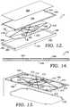
- FIG. 12depicts a top exploded perspective view of the vertically displaceable user platform, in accordance with an aspect hereof;
- FIG. 13depicts a bottom exploded perspective view similar to FIG. 12 , in accordance with an aspect hereof;
- FIG. 14depicts a cross section view taken along lines 14 - 14 of FIG. 12 , in accordance with an aspect hereof;
- FIG. 15depicts a top perspective view of a plurality of resistance/rebound mechanisms, in accordance with an aspect hereof;
- FIG. 16depicts a top perspective view of the resistance/rebound mechanisms of FIG. 15 with a user platform shown in dashed lines, in accordance with an aspect hereof;
- FIG. 17depicts a top plan view of the resistance/rebound mechanisms of FIG. 15 , in accordance with an aspect hereof;
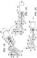
- FIG. 18depicts a top perspective view of one of the resistance/rebound mechanisms of FIG. 15 , in accordance with an aspect hereof;
- FIG. 19depicts a side elevation view of the resistance/rebound mechanism of FIG. 18 in a first position corresponding to the user platform being at a first vertical height, in accordance with an aspect hereof;
- FIG. 20depicts a side elevation view of the resistance/rebound mechanism of FIG. 18 in a second position corresponding to the user platform being at a second vertical height, in accordance with an aspect hereof;
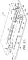
- FIG. 21depicts a top perspective view of a displacement-based lighting system with a user platform shown in dashed lines, in accordance with an aspect hereof;
- FIG. 22depicts a partial end perspective view of the displacement-based lighting system of FIG. 21 , in accordance with an aspect hereof;
- FIG. 23depicts a top perspective view of a linear encoder used in the displacement based lighting system of FIG. 21 , in accordance with an aspect hereof;
- FIG. 24depicts a top perspective view of the position-based speed control system, in accordance with an aspect hereof.
- FIG. 25depicts an exemplary method of operating a treadmill with a user platform movably attached to a base, in accordance with an aspect hereof.
- a treadmill 10 having an exemplary vertically displaceable platform 12is depicted.
- the treadmill 10has a base 14 for supporting the treadmill 10 on a suitable support surface.
- the platform 12is supported above the base 14 and is vertically movable to a number of different vertical locations in response to user interaction on an upper surface 16 . More specifically, the platform 12 is supported above the base 14 to allow the platform 12 to move relative to the base 14 in an up and down manner.
- the purpose of the up and down movement of the platform 12is to accommodate downward force exerted by a user on the upper surface 16 when preforming, for instance, a running or walking motion.
- the platform 12may be displaced downwardly with a resistance force as a user's foot strikes the platform 12 . Still further, as the user's foot is removed during a running motion, the platform may be moved upwardly with a rebound force in preparation for the user's other foot striking the upper surface 16 .
- An exemplary support structure for supporting the platform 12 for vertical movement above base 14is a vertical motion control mechanism 18 , as will be more fully described below.
- the treadmill 10also has an endless belt 20 that provides the moving surface for a user to engage during usage of the treadmill 10 .
- the belt 20has a fixed circumference and moves over the upper surface 16 of the platform 12 .
- the belt 20is moved beneath the user's feet to allow walking or running at a single location.
- the belt 20also moves under a bottom plate 22 of the base 14 .
- the bottom plate 22is supported above a ground surface by a plurality of generally trapezoidal legs 24 that are also part of the base 14 .
- the legs 24are positioned along opposite edges 26 of the plate 22 .
- the legs 24 along each edge 26are connected by a support rib 28 extending downwardly from a lower surface 30 of the bottom plate 22 .
- the plate 22also includes an upper surface 32 .
- the provision of a support rib 28 along each side of the bottom plate 22defines a cavity 34 through which the belt 20 passes adjacent the lower surface 30 of the bottom plate 22 . In this manner, the belt 20 is able to run in a continuous loop along the upper surface 16 of the platform 12 and along the lower surface 30 of the bottom plate 22 of the base 14 .
- a belt drive mechanism 36is depicted.
- the belt drive mechanism 36serves to provide the endless motion to the belt 20 so that the user has a continuous running/walking surface as the user moves across the upper surface 38 of the belt 20 .
- the belt drive mechanism 36is used to adjust the speed at which the user runs or walks. Any suitable control system can be used to adjust the speed of the belt drive mechanism 36 and correspondingly the speed of the belt 20 .
- the belt drive mechanism 36includes a drive roller 40 rotatably mounted to the base 14 by a pair of mounting brackets 42 positioned on opposite sides of the base 14 . Only one of the mounting brackets 42 is depicted in FIGS. 1 and 2 .
- the mounting brackets 42extend upwardly from the upper surface 32 of the plate 22 of the base 14 and each provide a pivot bearing 44 for receiving an axle 46 of the drive roller 40 .
- the provision of the axle 46 rotatably mounted in the pivot bearings 44allows the rotating motion of the drive roller 40 .
- the drive roller 40is coupled to any suitable power source to drive the rotating motion of the drive roller 40 and correspondingly the belt 20 .
- the power sourceis not depicted in the figures, but can include, for example, an electric motor or a hydraulic motor drivably coupled to the drive roller 40 by, for instance, a belt or chain system.
- the power sourcecan also be directly acting on the axle 46 to accomplish the rotating motion.
- the treadmill 10also includes a transition framework 48 for ensuring smooth transition of the belt 20 between the base 14 and the platform 12 , especially as the platform 12 is displaced between a number of vertical locations with respect to the base 14 during operation of the treadmill 10 .
- the transition framework 48also provides a stable surface that the user can use to get onto and off of the platform 12 .
- a dynamic belt tensioning mechanism 50is depicted and is disposed adjacent a forward end 52 of the treadmill 10 .
- the tensioning mechanism 50provides substantially constant tension on the belt 20 as the platform 12 moves up and down in relation to the base 14 . More specifically, the belt 20 has a fixed circumference. As the platform 12 moves up and down, the spatial relationship between the platform 12 and the base 14 is dynamically changing. Without the belt tensioning mechanism 50 , slack may exist in the belt 20 as the platform 12 moves downwardly towards the base 14 . This slack would result in possible disengagement of the belt 20 from the drive roller 40 . Still further, the slack may result in an unstable running surface on the upper surface 38 of the belt 20 .
- the belt tensioning mechanism 50provides a substantially constant tension in the belt 20 no matter the relative vertical position of the platform 12 above the base 14 .
- the platform 12further includes an operator support frame 54 that includes a pair of vertically extending pillars 56 fixedly mounted to opposite sides of the base 14 adjacent the lower ends 58 of the pillars 56 .
- the operator support frame 54further includes a console 60 mounted between and adjacent to the upper ends 62 of the pillars 56 .
- a pair of bracing arms 64extend rearwardly from opposite sides of the console 60 to provide lateral support and stability for a user as they engage with the platform 12 .
- the console 60can include various sensors (as will be more fully described below) and displays if desired to monitor or inform the user.
- the vertical control mechanism 18allows vertical motion of and minimizes roll and pitch of the platform 12 .
- the control mechanism 18includes a parallel pair of longitudinal scissor frameworks 100 positioned adjacent the opposite edges 26 of the bottom plate 22 of the base 14 and also a lateral scissor framework 102 positioned between and perpendicular to the longitudinal frameworks 100 near the midpoint of the plate 22 .
- each longitudinal scissor framework 100includes a first scissor arm 104 pivotally mounted to a second scissor arm 106 at a pivot/bearing arrangement 108 .
- a first/upper end 110 of the first scissor arm 104is pivotally connected to the platform 12 via a pivot/bearing mounting bracket 112 and a pivot/bearing 114 .
- a second/lower end 116 of the first scissor arm 104is slidably mounted to the upper surface 32 of the bottom plate 22 via a slide arrangement 118 .
- the slide arrangement 118includes a male protrusion 120 fixedly mounted to the upper surface 32 and a female mounting bracket 122 pivotally mounted to the second/lower end 116 via a pivot/bearing 114 .
- the female bracket 122is able to slide along the male protrusion 120 via a groove 124 formed in the female bracket 122 .
- the slide arrangement 118can be a profile rail linear bearing or any other suitable sliding/bearing mechanism.
- a first/lower end 126 of the second scissor arm 106is pivotally connected to the upper surface 32 of the plate 22 via a pivot/bearing mounting bracket 112 and a pivot/bearing 114 .
- a second/upper end 128 of the second scissor arm 106is slidably mounted to the platform 12 via a slide arrangement 118 .
- the slide arrangement 118includes a male protrusion 120 fixedly mounted to the platform 12 and a female mounting bracket 122 pivotally mounted to the second/upper end 128 via a pivot/bearing 114 .
- the lateral scissor framework 102includes a first scissor arm 130 pivotally mounted to a second scissor arm 132 at a pivot/bearing 108 .
- a first/upper end 134 of the first scissor arm 130is pivotally connected to the platform 12 via a pivot/bearing mounting bracket 112 and a pivot/bearing 114 .
- a second/lower end 136 of the first scissor arm 130is slidably mounted to the upper surface 32 of the bottom plate 22 via a slide arrangement 118 .
- the slide arrangement 118includes a male protrusion 120 fixedly mounted to the upper surface 32 and a female mounting bracket 122 pivotally mounted to the second/lower end 136 via a pivot/bearing 114 .
- the female bracket 122is able to slide along the male protrusion 120 via a groove 124 formed in the female bracket 122 .
- a first/lower end 138 of the second scissor arm 132is pivotally connected to the upper surface 32 of the plate 22 via a pivot/bearing mounting bracket 112 and a pivot/bearing 114 .
- a second/upper end 140 of the second scissor arm 132is slidably mounted to the platform 12 via a slide arrangement 118 .
- the slide arrangement 118includes a male protrusion 120 fixedly mounted to the platform 12 and a female mounting bracket 122 pivotally mounted to the second/upper end 140 via a pivot/bearing 114 .
- the provision of the parallel pair of longitudinal scissor frameworks 100 and the lateral scissor framework 102provides a stable support to allow the up and down vertical movement of the platform 12 relative to the base 14 . More specifically, the connection points of the frameworks 100 and 102 are positioned generally at all four corners of the platform 12 and also at the midpoint along the longitudinal sides of the platform 12 . In this manner, roll and pitch of the platform 12 may be minimized.
- the slide arrangements 118allow the pivoting action of the scissor arms of the longitudinal scissor frameworks 100 and the lateral scissor framework 102 . This pivoting action of the arms allows the stable vertical movement of the platform 12 relative to the base 14 .
- the friction and wear associated with the vertical movement of the platform 12is limited due to the limited friction points of the pivot/bearings 108 and 114 and the slide arrangements 118 . Wear, friction, and inertia may be reduced because of the limited ratio of rotation of the pivot/bearings 108 and 114 and the limited linear displacement on the linear bearing/slide arrangements 118 . Additionally due to the ratios of the arms of the scissor frameworks 100 and 102 , inertia may be reduced.
- the platform 12includes a platform base 200 formed of a relatively stiff material that allows the securement of the mounting brackets 112 and the sliding arrangements 118 of the longitudinal scissor frameworks 100 and the lateral scissor frameworks 102 .
- the exemplary platform base 200can be constructed of a metal material, such as aluminum, and provides a first layer for the platform 12 .
- the platform 12includes a thin phenolic sheet 202 received in a shallow cavity 204 that forms the upper surface 206 of the platform base 200 .
- the sheet 202may be bonded or otherwise attached to the upper surface 206 to provide a more limited coefficient of friction with the belt 20 .
- the platform base 200includes a latticed lower surface 208 including a plurality of ribs 210 extending downwardly and forming a plurality of cavities 212 .
- the latticed lower surface 208provides rigidity to the platform 12 and also provides attaching bosses 214 for securement of mounting brackets 112 and sliding arrangements 118 as described herein.
- the bosses 214also provide mounting surfaces for the resistance/rebound mechanisms, as will be more fully described below.
- the platform 12also includes an insert 216 constructed to fill the cavities 212 of the latticed lower surface 208 of the platform base 200 . More specifically, an upper surface 218 of the insert 216 includes a plurality of grooves 220 for receiving the ribs 210 of the platform base 200 . The upper surface 218 also includes apertures/recesses 222 for receiving the bosses 214 to facilitate mounting of the brackets 112 and the sliding arrangements 118 .
- the insert 216may be made of a foam inner layer 224 with a top relatively thin layer of carbon fiber 226 and a bottom relatively thin layer of carbon fiber 228 bonded thereto.
- the foamcan be polyurethane foam or any other suitable foam material.
- the carbon fiber/polyurethane sandwich construction of the insert 216helps to increase the section height of the platform 12 to increase stiffness with reduced mass.
- the design of the platform 12may therefore minimize or reduce the mass of the platform (and in turn reduce the inertia) while maintaining a natural frequency of over 200 Hz.
- the 200 Hz natural frequencyis chosen to reduce or minimize the effect of platform deflection when performing force measurements on the treadmill 10 , thus resulting in a more accurate load measurement.
- the platform 12also includes a frame 230 secured to the platform base 200 by any suitable structure such as, for example, bolts or rivets.
- the frame 230includes longitudinal side members 232 and lateral side members 234 which surround the platform base 200 .
- a pair of idler rollers 236are rotatably mounted between the longitudinal side members 232 adjacent a respective lateral side member 234 . The idler rollers 236 enhance the movement of the belt 20 over the upper surface 16 of the platform 12 .
- resistance/rebound mechanisms 300 a / 300 bare depicted for controlling the vertical displacement of the platform 12 in both the downwardly and upwardly directions.
- six resistance/rebound mechanisms 300 a / 300 bare depicted for controlling the motion of the platform 12 .
- the term “resistance” or “resistance force” as used hereinincludes the application of an upward force upon the platform 12 as the platform 12 is displaced downwardly during a foot strike such that the downward displacement is impeded. In this manner, the amount of downward displacement of the platform 12 that the user experiences during a foot strike can be selectively controlled.
- Each resistance/rebound mechanism 300 a / 300 bincludes a linear actuator 302 mounted to the upper surface 32 of the plate 22 by a vertical mounting bracket 304 .
- the mounting bracket 304engages a cylinder 306 of the actuator 302 and supports the actuator 302 in an orientation that is generally horizontal and parallel to the plate 22 .
- a movable piston 308Positioned within each cylinder 306 is a movable piston 308 .
- the piston 308moves in relationship to the cylinder 306 in a linear manner. Thus, the piston 308 moves linearly in a direction that is generally parallel to the plate 22 .
- Each actuator 302is able to both power the extension and the retraction of its piston 308 . It is the powering of the extension and retraction of the piston 308 that provides the resistance and rebound functions of the mechanisms 300 a / 300 b .
- One suitable exemplary actuatoris a voice coil actuator.
- Voice coil actuators (VCAs)are direct drive, limited motion devices that utilize a permanent magnet field and coil winding (conductor) to produce a force that is directly proportional to the electrical current applied to the coil.
- VCAsallow for a millimeter by millimeter control of both the resistance to the downward movement of the platform 12 and the rebounding upward movement of the platform 12 in the aspects described herein.
- a VCAcan provide a combined performance for response time, load capacity, parasitic damping, resolution, availability, system cost, packaging, and controls complexity.
- the VCAmay have in aspects hereof a response time in the 1 millisecond or lower range, which is sufficient to provide adequate responsiveness of the resistance/rebound force to the platform 12 .
- the VCAalso has a low internal damping due to the air gap, thus making it more nimble to control than other actuators, in certain circumstances.
- Each actuator 302also has a buffer spring 310 that is positioned around the piston 308 and between the cylinder front end 312 and an annular flange 314 fixed to the piston 308 .
- the spring 310can further smooth the application of the resistance and rebound forces to the platform 12 .
- the springs 310also may help to reduce the level of actuator current that is required to hold the platform 12 in its neutral position. In other words, the springs 310 serve to keep the platform 12 up when no power is supplied to an actuator 302 .
- a first end 316 of the piston 308is pivotally connected to a first end 318 of an actuator linkage 320 by a pin/ball joint 322 .
- a second end 323 of the linkage 320is pivotally connected to a first pivot connection point 324 of a bell crank 326 by a pin/ball joint 322 .
- each bell crank 326serves to convert the horizontal resistance/rebound force of its respective actuator 302 to a generally vertical resistance/rebound force that is applied to the platform 12 .
- Each bell crank 326is pivotally mounted between a pair of vertical support frames 328 attached to and extending upwardly from the upper surface 32 of the plate 22 .
- a pivot axle 330is used to mount the bell cranks 326 between the respective support frames 328 and allow clockwise and counterclockwise rotation of the bell crank 326 .
- Each bell crank 326has a second connection point 332 pivotally attached to a first end 334 of a platform linkage 336 by a pin/ball joint 322 .
- a second end 338 of the platform linkage 336is pivotally connected to the platform 12 via a pin/ball joint 322 and a mounting bracket 340 .
- Each mounting bracket 340is attached to a boss 214 formed on the lower surface 208 of the platform base 200 .
- Each platform linkage 336can have a load cell transducer 342 for measuring the force input to the platform 12 , as shown most clearly in FIG. 18 .
- FIGS. 18-20the translation of the horizontal resistance/rebound motion of the actuator 302 to a substantially vertical resistance/rebound motion is described.
- a downward forceis applied to the platform 12 by for instance a foot strike of a runner, the platform 12 is vertically displaced downwardly in a stable manner by the vertical motion control mechanism 18 .
- Each resistance/rebound mechanism 300 a / 300 bwill resist the downward displacement of the platform 12 to a certain degree, depending on the desired performance/measurement characteristics of the treadmill 10 .
- the resistanceis applied to the platform 12 via the mounting brackets 340 fixedly attached to the platform base 200 and pivotally attached to the platform linkage 336 .
- the bell crank 326As the platform 12 moves downwardly, the bell crank 326 is rotated in a counterclockwise direction about the pivot axle 330 . As depicted in FIG. 20 , the counterclockwise motion of the bell crank 326 results in retraction of the piston 308 of the linear actuator 302 . This retraction is controlled by the actuator 302 applying a resistance force. In this manner, the amount of displacement of the platform 12 can be controlled on, for instance, a millimeter by millimeter basis. As is apparent, if it is desirable to apply a rebound force to platform 12 such that an upward force is applied to a runners foot, the linear actuator 302 is energized to extend the piston 308 to apply the rebound force.
- the extension of piston 308results in clockwise motion of the bell crank 326 and, thus, the application of a vertically upward rebound force to the platform 12 via the linkage 336 .
- the amount of rebound forcecan be applied in a tuned manner to enhance the performance and measurement capabilities of the treadmill 10 .
- the load cell transducers 342can be used to measure the force inputs on the platform 12 applied by a user. The measurements from transducers 342 can be used to adjust the resistance/rebound forces applied to the platform 12 by the actuators 302 .
- the bell cranks 326amplify the parallel linear motion of the actuators 302 such that the vertical motion traveled is greater than the horizontal linear motion.
- the distance D 2 between the second connection point 332 of the bell crank 326 and the pivot axle 330is greater than the distance D 1 between the first connection point 324 and the pivot axle 330 .
- the relationship of D 2 being greater than D 1results in any movement of the piston 308 being amplified such that the actual upward or downward vertical movement of the platform 12 is greater than that of the extension or retraction travel of the piston 308 .
- resistance/rebound mechanisms 300 a / 300 ballow for the compact positioning of the linear actuators 302 by allowing them to be positioned generally horizontally with the force converted vertically, but they also amplify the travel distance of the linear actuator 302 as it is applied to the platform 12 .
- the six resistance/rebound mechanisms 300 a / 300 bare positioned generally toward the interior of the plate 22 .
- the longitudinal scissor frameworks 100are positioned on each side of the cluster of the resistance/rebound mechanisms 300 a / 300 b .
- the lateral scissor framework 102cuts through the center of the cluster of resistance/rebound mechanisms 300 a / 300 b .
- Each of the four peripheral resistance/rebound mechanisms 300 aare connected to the platform base 200 at center connection points 344 via a suitable boss 214 .
- Each of the two intermediate resistance/rebound mechanisms 300 bare connected to the platform base 200 at connection points 346 adjacent the midpoints of the lateral edges of the platform 12 .
- Any suitable control system 348can be used to actuate the resistance/rebound mechanisms 300 .
- VCAsare used as the resistance/rebound mechanisms 300 a / 300 b and the control system 348 is electrical in nature, each resistance/rebound mechanism 300 a / 300 b may then be electrically connected to the control system 348 via electrical connections 350 .
- the control system 348provides electrical signals/input to the resistance/rebound mechanisms 300 a / 300 b so that downward displacement of the platform 12 is impeded/resisted by application of a force to the platform 12 and upward displacement is enhanced/rebounded also by applying a force to the platform 12 .
- Measurement inputs from the load cell transducers 342can be supplied to the control system 348 and used to determine the appropriate electrical/inputs to send to actuators 302 .
- the control system 348can be used to simulate a wide variety of running surfaces (e.g., sand, gravel, etc.) through adjustment of the resistance and rebound forces applied by the mechanisms 300 a / 300 b to the platform 12 .
- a displacement-based lighting system 400is depicted and is capable of visually indicating the vertical downward displacement of the platform 12 from a normalized start position.
- the lighting system 400includes three linear encoders 402 a / 402 b positioned between and coupled to the platform 12 and the plate 22 of the base 14 .
- Two of the linear encoders 402 aare mounted adjacent the front end 404 of the plate 22 via mounting structures 406 .
- the mounting structures 406are secured to the upper surface 32 of the plate 22 .
- a side surface 408 of the linear encoders 402 ais attached to a respective mounting structure 406 .
- Each linear encoder 402 a / 402 bhas a linear displaceable measurement piston 410 that is movable within the housing 412 of the encoder 402 a / 402 b .
- As the piston 410 moves within the housing 412an amount of displacement is sensed and an appropriate signal is sent via an electrical line 414 connected to the housing 412 .
- An upper end 416 of the piston 410is attached to the platform 12 such that up and down movement of the platform 12 cause linear movement of the piston 410 within the housing 412 .
- the encoders 402 a / 402 bcan sense the displacement of the platform 12 and send an appropriate signal.
- the lighting system 400further includes a rear linear encoder 402 b mounted to and adjacent a rear edge 418 of the plate 22 .
- the encoder 402 bhas a lower mounting shaft 420 secured to the upper surface 32 of the plate 22 via a bracket arrangement (not shown).
- the upper end 416 of the encoder 402 bsecures to the platform 12 and the encoder 402 b operates in the same manner as the encoders 402 a.
- the lighting system 400also includes horizontally extending elongated lighting arrangements 422 .
- the lighting arrangements 422are mounted to the upper surface 32 of the plate 22 by brackets 424 and are capable of illuminating different colors corresponding to the displacement value of the platform 12 .
- One suitable type of lighting arrangement 422is a string LED (light emitting diode) which can illuminate for instance the colors green, yellow, and/or red with various intensities thereof.
- Each lighting arrangement 422is electrically connected (either directly or indirectly) to the encoders 402 via electrical line 414 .
- the lighting system 400is used on the treadmill 10 to inform the operator on the level of peak displacement that is being seen by the runner for each stride.
- the encoders 402are used to sense the displacement of the platform 12 and to send and appropriate signal to the lighting arrangements 422 to reflect a specific color that corresponds to the displacement.
- one suitable color indication scaleis: green is 0-15 mm, yellow is 15-30 mm, and red is over 30 mm. Other scales may be utilized for particular lighting segmentations.
- Lighting arrangements 422can also be used to reflect additional treadmill information such as, for instance, the state of the treadmill 10 . When the treadmill 10 is ready for use. the lighting arrangements 422 may turn dark green and when there is a fault with the treadmill 10 , the lighting arrangement may turn dark red.
- a position-sensor-based speed control system 500is depicted and is capable of sensing the position of the runner/walker and adjusting the speed of the treadmill 10 based upon the runner's position on the platform 12 .
- the speed control system 500includes a sensor 502 positioned on a user-facing surface 504 of the console 60 .
- the sensor 502can send out a signal 506 that is capable of determining the position of a treadmill user along the longitudinal length of the platform 12 .
- the sensor 502points towards the runner/user and can determine the distance from the sensor 502 to the runner/user.
- the belt 20can be sped up or slowed down to keep the user in the middle of the platform 12 .
- One suitable type of sensor 502is an infrared sensor.
- the speed control system 500can be used to actively control the speed of the belt 20 to slow the speed as the runner slows due to fatigue without manual speed adjustment.
- a method 600 of operating a treadmill, such as the treadmill 10 described herein, with a base, such as the base 14 described herein, and a vertically displaceable platform, such as the platform 12 described herein,is depicted.
- the method 600includes the step 602 of resisting the downward movement of the platform in response to a control input indicating a load is applied to the platform.
- the resistance applied to the platformmay be controllable at every millimeter of travel in the downward direction.
- the method 600also includes the step 604 of rebounding the platform upwardly with a force applied to the platform in response to a control signal indicating a decrease of a load on the platform.
- the rebound responsiveness of the platformmay be controllable at every millimeter of travel in the upward direction.
Landscapes
- Health & Medical Sciences (AREA)
- General Health & Medical Sciences (AREA)
- Physical Education & Sports Medicine (AREA)
- Cardiology (AREA)
- Vascular Medicine (AREA)
- Rehabilitation Tools (AREA)
Abstract
Description
Claims (8)
Priority Applications (9)
| Application Number | Priority Date | Filing Date | Title |
|---|---|---|---|
| US15/991,499US10918904B2 (en) | 2017-05-31 | 2018-05-29 | Treadmill with vertically displaceable platform |
| EP18733432.1AEP3630308B1 (en) | 2017-05-31 | 2018-05-31 | Treadmill with vertically displaceable platform |
| CN202310002630.1ACN115920306A (en) | 2017-05-31 | 2018-05-31 | Treadmill with vertically shiftable platform |
| PCT/US2018/035368WO2018222855A1 (en) | 2017-05-31 | 2018-05-31 | Treadmill with vertically displaceable platform |
| CN201880035689.8ACN110678230B (en) | 2017-05-31 | 2018-05-31 | Treadmill with vertically displaceable platform |
| US17/153,647US11666799B2 (en) | 2017-05-31 | 2021-01-20 | Treadmill with vertically displaceable platform |
| US17/180,396US11491365B2 (en) | 2017-05-31 | 2021-02-19 | Treadmill with vertically displaceable platform |
| US18/138,932US12324952B2 (en) | 2017-05-31 | 2023-04-25 | Treadmill with vertically displaceable platform |
| US19/067,619US20250195945A1 (en) | 2017-05-31 | 2025-02-28 | Treadmill with vertically displaceable platform |
Applications Claiming Priority (3)
| Application Number | Priority Date | Filing Date | Title |
|---|---|---|---|
| US201762512770P | 2017-05-31 | 2017-05-31 | |
| US201762512769P | 2017-05-31 | 2017-05-31 | |
| US15/991,499US10918904B2 (en) | 2017-05-31 | 2018-05-29 | Treadmill with vertically displaceable platform |
Related Child Applications (1)
| Application Number | Title | Priority Date | Filing Date |
|---|---|---|---|
| US17/153,647DivisionUS11666799B2 (en) | 2017-05-31 | 2021-01-20 | Treadmill with vertically displaceable platform |
Publications (2)
| Publication Number | Publication Date |
|---|---|
| US20180345068A1 US20180345068A1 (en) | 2018-12-06 |
| US10918904B2true US10918904B2 (en) | 2021-02-16 |
Family
ID=62705710
Family Applications (5)
| Application Number | Title | Priority Date | Filing Date |
|---|---|---|---|
| US15/991,499Active2038-07-16US10918904B2 (en) | 2017-05-31 | 2018-05-29 | Treadmill with vertically displaceable platform |
| US17/153,647ActiveUS11666799B2 (en) | 2017-05-31 | 2021-01-20 | Treadmill with vertically displaceable platform |
| US17/180,396ActiveUS11491365B2 (en) | 2017-05-31 | 2021-02-19 | Treadmill with vertically displaceable platform |
| US18/138,932ActiveUS12324952B2 (en) | 2017-05-31 | 2023-04-25 | Treadmill with vertically displaceable platform |
| US19/067,619PendingUS20250195945A1 (en) | 2017-05-31 | 2025-02-28 | Treadmill with vertically displaceable platform |
Family Applications After (4)
| Application Number | Title | Priority Date | Filing Date |
|---|---|---|---|
| US17/153,647ActiveUS11666799B2 (en) | 2017-05-31 | 2021-01-20 | Treadmill with vertically displaceable platform |
| US17/180,396ActiveUS11491365B2 (en) | 2017-05-31 | 2021-02-19 | Treadmill with vertically displaceable platform |
| US18/138,932ActiveUS12324952B2 (en) | 2017-05-31 | 2023-04-25 | Treadmill with vertically displaceable platform |
| US19/067,619PendingUS20250195945A1 (en) | 2017-05-31 | 2025-02-28 | Treadmill with vertically displaceable platform |
Country Status (4)
| Country | Link |
|---|---|
| US (5) | US10918904B2 (en) |
| EP (1) | EP3630308B1 (en) |
| CN (2) | CN115920306A (en) |
| WO (1) | WO2018222855A1 (en) |
Families Citing this family (7)
| Publication number | Priority date | Publication date | Assignee | Title |
|---|---|---|---|---|
| US10918904B2 (en)* | 2017-05-31 | 2021-02-16 | Nike, Inc. | Treadmill with vertically displaceable platform |
| US10857421B2 (en)* | 2017-05-31 | 2020-12-08 | Nike, Inc. | Treadmill with dynamic belt tensioning mechanism |
| CN107854807B (en)* | 2017-11-27 | 2023-06-30 | 北京小米移动软件有限公司 | Running board assembly and running machine |
| CN107773913B (en)* | 2017-11-27 | 2020-09-11 | 北京小米移动软件有限公司 | Running board assembly and treadmill |
| US10898753B2 (en)* | 2018-05-31 | 2021-01-26 | Board Of Regents, The University Of Texas System | Treadmills having adjustable surface stiffness |
| US11181428B2 (en) | 2019-11-21 | 2021-11-23 | Thomas Michael Baer | Systems and methods for detecting running and walking strides and foot strikes |
| US11465031B2 (en)* | 2020-09-16 | 2022-10-11 | RevolutioNice, Inc. | Ambulation simulation systems, terrain simulation systems, treadmill systems, and related systems and methods |
Citations (83)
| Publication number | Priority date | Publication date | Assignee | Title |
|---|---|---|---|---|
| US3142193A (en) | 1961-11-20 | 1964-07-28 | Int Harvester Co | Belt tensioning device |
| US3731917A (en) | 1971-02-25 | 1973-05-08 | Townsend Engineering Co | Treadmill exercising device |
| US3762229A (en) | 1972-07-10 | 1973-10-02 | Hamilton Brothers Mfg Co | Variable power ratio device |
| US3921793A (en) | 1974-07-08 | 1975-11-25 | Goodman Sigmund | Reversible belt tensioning system |
| US4566689A (en) | 1980-08-05 | 1986-01-28 | Ajay Enterprises Corporation | Adjustable motor mount arrangement for exercise treadmills |
| US4602779A (en) | 1980-08-05 | 1986-07-29 | Ajax Enterprises Corporation | Exercise treadmill |
| US4635928A (en) | 1985-04-15 | 1987-01-13 | Ajax Enterprises Corporation | Adjustable speed control arrangement for motorized exercise treadmills |
| GB2196266A (en) | 1986-10-14 | 1988-04-27 | Ind Tech Res Inst | Track means and handrail structure for a treadmill |
| US4747810A (en) | 1979-07-10 | 1988-05-31 | Deere & Company | Belt drive with self-aligning idler |
| US4849666A (en) | 1987-12-29 | 1989-07-18 | The Charles Stark Draper Laboratory, Inc. | Electromagnetic isolator/actuator system |
| US4974831A (en) | 1990-01-10 | 1990-12-04 | Precor Incorporated | Exercise treadmill |
| US4984810A (en) | 1987-11-25 | 1991-01-15 | Stearns & Mcgee | Treadmill |
| US5015926A (en) | 1990-02-02 | 1991-05-14 | Casler John A | Electronically controlled force application mechanism for exercise machines |
| US5302162A (en) | 1992-11-05 | 1994-04-12 | Precor Incorporated | Exercise treadmill with tension-limited belt adjustment |
| US5336146A (en) | 1993-12-15 | 1994-08-09 | Piaget Gary D | Treadmill with dual reciprocating treads |
| US5382207A (en) | 1989-06-19 | 1995-01-17 | Life Fitness | Exercise treadmill |
| US5478027A (en) | 1985-04-24 | 1995-12-26 | Alexander Machinery, Inc. | Web unwinding apparatus and method |
| US5529553A (en) | 1995-02-01 | 1996-06-25 | Icon Health & Fitness, Inc. | Treadmill with belt tensioning adjustment |
| US5542892A (en) | 1994-08-15 | 1996-08-06 | Unisen, Inc. | Supporting chassis for a treadmill |
| US5752879A (en) | 1995-12-13 | 1998-05-19 | Berdut; Elberto | Tiltable multi-purpose exercise gym apparatus |
| US5860894A (en) | 1994-02-03 | 1999-01-19 | Icon Health & Fitness, Inc. | Aerobic and anaerobic exercise machine |
| US5893530A (en) | 1996-08-28 | 1999-04-13 | Alexander Machinery, Inc. | Cushioning apparatus for web roll let-off and method |
| US5993358A (en)* | 1997-03-05 | 1999-11-30 | Lord Corporation | Controllable platform suspension system for treadmill decks and the like and devices therefor |
| US6013011A (en) | 1997-03-31 | 2000-01-11 | Precor Incorporated | Suspension system for exercise apparatus |
| US6053848A (en) | 1998-08-24 | 2000-04-25 | Eschenbach; Paul William | Treadmill deck suspension |
| WO2001030464A1 (en) | 1999-10-22 | 2001-05-03 | Jonathan Mark Burling Showan | Apparatus for simulating a ski slope |
| WO2001056664A1 (en) | 2000-01-31 | 2001-08-09 | Technogym S.R.L. | Treadmill exercise device |
| KR20010083808A (en) | 2001-06-29 | 2001-09-03 | 이상민 | Belt support apparatus for running machine |
| US6287240B1 (en) | 1999-08-09 | 2001-09-11 | Michael J. Trabbic | Variable resistance treadmill for simultaneously simulating a rolling and sliding resistance, and a moving inertia |
| US6394239B1 (en)* | 1997-10-29 | 2002-05-28 | Lord Corporation | Controllable medium device and apparatus utilizing same |
| US6409633B1 (en) | 1998-05-30 | 2002-06-25 | Kevin G. Abelbeck | Moving surface exercise device |
| US6436008B1 (en) | 1989-06-19 | 2002-08-20 | Brunswick Corporation | Exercise treadmill |
| US6607469B2 (en) | 2000-09-12 | 2003-08-19 | Ohtake Root Kogyo Co., Ltd. | Running machine |
| US6652424B2 (en) | 1998-09-25 | 2003-11-25 | William T. Dalebout | Treadmill with adjustable cushioning members |
| US6776740B1 (en) | 1999-09-07 | 2004-08-17 | Brunswick Corporation | Treadmill mechanism |
| US6811519B2 (en) | 2003-03-27 | 2004-11-02 | Hai Pin Kuo | Dual treadmill having adjustable resistance |
| US6821230B2 (en) | 1998-09-25 | 2004-11-23 | Icon Ip, Inc. | Treadmill with adjustable cushioning members |
| US20040259690A1 (en) | 2002-03-21 | 2004-12-23 | Frykman Peter N. | Method for interpreting forces and torques exerted by a left and right foot on a dual-plate treadmill |
| US20050009668A1 (en) | 2003-07-10 | 2005-01-13 | Greg Savettiere | Elliptical/treadmill exercise apparatus |
| US20050032610A1 (en) | 2000-02-02 | 2005-02-10 | Gerald Nelson | Incline assembly with cam |
| US20050045452A1 (en) | 2003-07-01 | 2005-03-03 | Hansrudolf Iseli | Device for tensioning and loosening of an endless conveyor belt which is guided over deflection means |
| US6878100B2 (en) | 2002-03-21 | 2005-04-12 | The United States Of America As Represented By The Secretary Of The Army | Force sensing treadmill |
| US20050164839A1 (en) | 2004-01-09 | 2005-07-28 | Watterson Scott R. | Cushioning treadmill |
| EP1606026A2 (en) | 2003-02-28 | 2005-12-21 | Nautilus, Inc. | System and method for controlling an exercise apparatus |
| US20060160669A1 (en) | 2004-12-13 | 2006-07-20 | Lizarralde Inigo I | Linear-response resistance system for exercise equipment |
| US7156777B2 (en) | 2002-06-28 | 2007-01-02 | Precor Incorporated | Adjustable exercise device |
| WO2007016555A2 (en) | 2005-08-01 | 2007-02-08 | Fitness Quest Inc. | Exercise treadmill |
| EP1400263B1 (en) | 2002-08-27 | 2007-03-21 | TECHNOGYM S.p.A. | A damping support device for an exercise apparatus |
| US7241250B1 (en) | 1907-06-27 | 2007-07-10 | Hydroworx | Hydrotherapy and exercise device with integrated lift and treadmill means |
| EP1815887A1 (en) | 2006-01-19 | 2007-08-08 | Hai-Pin Kuo | Treadmill having changeable suspension |
| US20070281832A1 (en) | 2006-04-10 | 2007-12-06 | Nerio Alessandri | Gymnastic machine |
| US7367926B2 (en) | 2005-08-01 | 2008-05-06 | Fitness Quest Inc. | Exercise treadmill |
| WO2008099429A1 (en) | 2007-02-14 | 2008-08-21 | Cammax S.A. | Treadmill with endless belt tension adjusting device |
| US20080242511A1 (en) | 2007-03-26 | 2008-10-02 | Brunswick Corporation | User interface methods and apparatus for controlling exercise apparatus |
| US20080312047A1 (en) | 2007-06-18 | 2008-12-18 | Johnson Health Tech Co., Ltd | Treadmill |
| US7507187B2 (en) | 2004-04-06 | 2009-03-24 | Precor Incorporated | Parameter sensing system for an exercise device |
| US7513852B2 (en) | 2003-06-18 | 2009-04-07 | Scott & Wilkins Enterprises, Llc | Exercise device having position verification feedback |
| US7563203B2 (en) | 1998-09-25 | 2009-07-21 | Icon Ip, Inc. | Treadmill with adjustable cushioning members |
| US7645212B2 (en) | 2000-02-02 | 2010-01-12 | Icon Ip, Inc. | System and method for selective adjustment of exercise apparatus |
| US20100160115A1 (en) | 2008-12-19 | 2010-06-24 | Unisen, Inc., Dba Star Trac | User detection for exercise equipment |
| US7874963B2 (en) | 2008-12-29 | 2011-01-25 | Precor Incorporated | Exercise device with adaptive curved track motion |
| US20110281692A1 (en) | 2006-03-06 | 2011-11-17 | Maresh Joseph D | Treadmill apparatus |
| US8172729B2 (en) | 2009-11-16 | 2012-05-08 | Ellis Joseph K | Exercise treadmill for simulating pushing and pulling actions and exercise method therefor |
| US20120184409A1 (en) | 2011-01-19 | 2012-07-19 | Adam Morris Beal | Endless Belt Arm Exercise Device With Braking Mechanism |
| WO2013138375A1 (en) | 2012-03-12 | 2013-09-19 | Core Industries, Llc | Apparatus, system, and method for providing resistance in a dual tread treadmill |
| US20130267386A1 (en) | 2012-04-06 | 2013-10-10 | Strength Master Fitness Tech Co., Ltd. | Foldable treadmill having lifting mechanism |
| US8597161B2 (en)* | 2010-08-10 | 2013-12-03 | Nautilus, Inc. | Motorless treadmill stepper exercise device |
| EP2673056A2 (en) | 2011-02-07 | 2013-12-18 | Gerald M. Clum | Shock-absorbing treadmill |
| US20140011642A1 (en) | 2009-11-02 | 2014-01-09 | Alex Astilean | Leg-powered treadmill |
| EP2762204A1 (en) | 2013-02-05 | 2014-08-06 | Strength Master Fitness Tech Co., Ltd. | Tilting and folding device for a treadmill |
| US20140274577A1 (en) | 2013-03-12 | 2014-09-18 | David Beard | Apparatus, system, and method for dual tread treadmill improvements |
| US8968160B2 (en) | 2007-06-15 | 2015-03-03 | Cybex International, Inc. | Treadmill belt support assembly |
| US8979709B2 (en) | 2010-03-26 | 2015-03-17 | Sproing Fitness LLC | Exercise apparatus |
| US20150151156A1 (en) | 2003-02-28 | 2015-06-04 | Nautilus, Inc. | Exercise device with treadles |
| US9233267B2 (en) | 2012-12-20 | 2016-01-12 | Wilkins Ip, Llc | Adjustable rebound device and exercise machine including adjustable rebound device |
| US20160023045A1 (en) | 2014-07-25 | 2016-01-28 | Icon Health & Fitness, Inc. | Determining Work Performed on a Treadmill |
| WO2016065077A1 (en) | 2014-10-23 | 2016-04-28 | Corepact, Llc | Cordless treadmill |
| US20160144225A1 (en) | 2014-11-26 | 2016-05-26 | Icon Health & Fitness, Inc. | Treadmill with a Tensioning Mechanism for a Slatted Tread Belt |
| US9352186B2 (en) | 2012-04-05 | 2016-05-31 | Icon Health & Fitness, Inc. | Treadmill with selectively engageable deck stiffening mechanism |
| US9367668B2 (en) | 2012-02-28 | 2016-06-14 | Precor Incorporated | Dynamic fitness equipment user interface adjustment |
| US9370686B2 (en) | 2011-09-28 | 2016-06-21 | Byung Don Lee | Treadmill |
| US20160289006A1 (en) | 2015-03-30 | 2016-10-06 | Joy Mm Delaware, Inc. | Take-up mechanism for conveyor system |
| US20160367851A1 (en) | 2009-11-02 | 2016-12-22 | Speedfit LLC | Leg-powered treadmill |
Family Cites Families (50)
| Publication number | Priority date | Publication date | Assignee | Title |
|---|---|---|---|---|
| US2257758A (en) | 1939-06-15 | 1941-10-07 | American Can Co | Chain tightener device |
| US2506579A (en) | 1947-05-10 | 1950-05-09 | Goodman Mfg Co | Tensioning device for articulating conveyers |
| US3064797A (en) | 1960-07-06 | 1962-11-20 | Besel Wilhelm | Automatic tensioning devicf for conveyor belts |
| GB1144818A (en) | 1966-11-30 | 1969-03-12 | Thompson Brothers Engineers Lt | Improvements in or relating to winches |
| US3479852A (en) | 1967-04-21 | 1969-11-25 | Archer Products Inc | Rolling apparatus for rounding the edges of strip metal |
| US3870297A (en)* | 1973-06-18 | 1975-03-11 | Del Mar Eng Lab | Exercise treadmill with inclination controlled chair mounted thereon |
| DK253574A (en) | 1974-05-09 | 1975-11-10 | Mark & Wedell Ap S | ERGOMETER |
| US4193315A (en) | 1978-02-06 | 1980-03-18 | The Maytag Company | Belt drive system utilizing an adjustable idler mechanism |
| US4253343A (en) | 1979-07-10 | 1981-03-03 | Deere & Company | Belt drive system with adjustably gauged tightener means |
| CA1155318A (en) | 1979-07-10 | 1983-10-18 | Robert D. Black | Belt drive with split idler means |
| CA1135533A (en) | 1980-11-24 | 1982-11-16 | Derald H. Kraft | Hydraulic belt tensioner construction |
| US5014979A (en) | 1990-04-25 | 1991-05-14 | Mccain Manufacturing Corporation | Signature machine |
| US5336145A (en)* | 1991-08-30 | 1994-08-09 | Keiser Dennis L | Apparatus having a movable load bearing surface |
| CN2245471Y (en)* | 1995-10-12 | 1997-01-22 | 国帅工业股份有限公司 | treadmill transmission |
| AU733717B2 (en)* | 1996-08-27 | 2001-05-24 | David E.E. Carmein | Omni-directional treadmill |
| TW339663U (en) | 1997-09-18 | 1998-09-01 | Fu-Yong Qiu | Improved structure of a jogging machine pedal |
| US6202397B1 (en) | 1999-05-27 | 2001-03-20 | Deere & Company | Draper belt tensioning mechanism for a harvesting platform |
| WO2001056668A1 (en) | 2000-02-03 | 2001-08-09 | American Golf Technologies, Inc. | Portable, weather resistant golf practice device |
| TW529432U (en)* | 2002-06-03 | 2003-04-21 | Huang-Dung Jang | Lifting and folding structure of jogging treadmill |
| US7645214B2 (en) | 2004-02-26 | 2010-01-12 | Nautilus, Inc. | Exercise device with treadles |
| US20070049465A1 (en)* | 2005-08-30 | 2007-03-01 | Shen Yi Wu | Buffer apparatus of a treadmill |
| BRPI0602943B1 (en)* | 2006-06-30 | 2017-05-23 | Brudden Equip | treadmill belt misalignment flag |
| US20080119337A1 (en)* | 2006-10-20 | 2008-05-22 | Wilkins Larry C | Exercise device with features for simultaneously working out the upper and lower body |
| JP4113555B2 (en) | 2006-11-29 | 2008-07-09 | 國新産業株式会社 | Running machine belt |
| WO2010118956A1 (en) | 2009-04-15 | 2010-10-21 | Kybun Ag | Belt for a treadmill and training equipment having a belt |
| US8206801B2 (en) | 2009-11-06 | 2012-06-26 | Huang-Tung Chang | Buffer board for treadmill |
| TWM382834U (en) | 2009-12-18 | 2010-06-21 | Chun-Liang Wu | Buffer shock-absorbing structure of treadmill |
| US8986176B2 (en) | 2010-02-03 | 2015-03-24 | Lani Renae Arst | Isoped exercise device |
| CN202446766U (en) | 2011-10-25 | 2012-09-26 | 河北路德医疗器械有限公司 | Swing machine core of horse riding body-building machine |
| US9430920B2 (en)* | 2014-03-12 | 2016-08-30 | Precor Incorporated | Treadmill belt wear notification system |
| CN106659923A (en)* | 2014-08-29 | 2017-05-10 | 爱康保健健身有限公司 | Laterally tilting treadmill deck |
| TWI546103B (en) | 2014-12-30 | 2016-08-21 | Zhong-Fu Zhang | Treadmill of the buffer plate structure |
| US20180043207A1 (en) | 2015-04-02 | 2018-02-15 | George Moser | Treadmill |
| US9814929B2 (en) | 2015-04-02 | 2017-11-14 | George Moser | Treadmill |
| CN104801012A (en)* | 2015-05-21 | 2015-07-29 | 合肥扁豆智能科技有限公司 | Ultra-thin running machine with foldable running surface |
| US12005302B2 (en) | 2015-06-01 | 2024-06-11 | Johnson Health Tech Co., Ltd | Exercise apparatus |
| US10857407B2 (en) | 2015-06-01 | 2020-12-08 | Johnson Health Tech Co., Ltd. | Exercise apparatus |
| US11135472B2 (en) | 2015-06-01 | 2021-10-05 | Johnson Health Tech Co., Ltd. | Exercise apparatus |
| ITUB20160357A1 (en)* | 2016-01-26 | 2017-07-26 | Rx S P A | Treadmill for physical exercise |
| CA2962298C (en) | 2016-03-30 | 2019-08-20 | Clark Walter | Treadmill belts that enhance a user's comfort and stability |
| US10589146B2 (en) | 2016-05-19 | 2020-03-17 | Sara Becker | Exercise treadmill with selectable running surface |
| CN106390369B (en)* | 2016-05-27 | 2019-07-02 | 深圳市好家庭实业有限公司 | Carbon fiber shock absorption treadmill and fitness equipment |
| CN106110573B (en) | 2016-07-28 | 2019-05-14 | 京东方科技集团股份有限公司 | Omni-mobile platform and its control method, treadmill |
| US10416754B2 (en)* | 2017-01-30 | 2019-09-17 | Disney Enterprises, Inc. | Floor system providing omnidirectional movement of a person walking in a virtual reality environment |
| US10918904B2 (en) | 2017-05-31 | 2021-02-16 | Nike, Inc. | Treadmill with vertically displaceable platform |
| US10857421B2 (en) | 2017-05-31 | 2020-12-08 | Nike, Inc. | Treadmill with dynamic belt tensioning mechanism |
| WO2018232415A1 (en) | 2017-06-16 | 2018-12-20 | Core Health & Fitness, Llc | Apparatus, system, and method for flexible treadmill deck |
| US10816177B1 (en)* | 2017-06-30 | 2020-10-27 | Woodway Usa, Inc. | Lighting system and method of using same with exercise and rehabilitation equipment |
| US10898753B2 (en)* | 2018-05-31 | 2021-01-26 | Board Of Regents, The University Of Texas System | Treadmills having adjustable surface stiffness |
| US20220062698A1 (en) | 2020-09-01 | 2022-03-03 | Yu-Lun TSAI | Treadmill Walking Board Assembly Having Functions of Flow Guidance, Air Exhaust and Heat Dissipation |
- 2018
- 2018-05-29USUS15/991,499patent/US10918904B2/enactiveActive
- 2018-05-31CNCN202310002630.1Apatent/CN115920306A/enactivePending
- 2018-05-31WOPCT/US2018/035368patent/WO2018222855A1/ennot_activeCeased
- 2018-05-31CNCN201880035689.8Apatent/CN110678230B/enactiveActive
- 2018-05-31EPEP18733432.1Apatent/EP3630308B1/enactiveActive
- 2021
- 2021-01-20USUS17/153,647patent/US11666799B2/enactiveActive
- 2021-02-19USUS17/180,396patent/US11491365B2/enactiveActive
- 2023
- 2023-04-25USUS18/138,932patent/US12324952B2/enactiveActive
- 2025
- 2025-02-28USUS19/067,619patent/US20250195945A1/enactivePending
Patent Citations (86)
| Publication number | Priority date | Publication date | Assignee | Title |
|---|---|---|---|---|
| US7241250B1 (en) | 1907-06-27 | 2007-07-10 | Hydroworx | Hydrotherapy and exercise device with integrated lift and treadmill means |
| US3142193A (en) | 1961-11-20 | 1964-07-28 | Int Harvester Co | Belt tensioning device |
| US3731917A (en) | 1971-02-25 | 1973-05-08 | Townsend Engineering Co | Treadmill exercising device |
| US3762229A (en) | 1972-07-10 | 1973-10-02 | Hamilton Brothers Mfg Co | Variable power ratio device |
| US3921793A (en) | 1974-07-08 | 1975-11-25 | Goodman Sigmund | Reversible belt tensioning system |
| US4747810A (en) | 1979-07-10 | 1988-05-31 | Deere & Company | Belt drive with self-aligning idler |
| US4602779A (en) | 1980-08-05 | 1986-07-29 | Ajax Enterprises Corporation | Exercise treadmill |
| US4566689A (en) | 1980-08-05 | 1986-01-28 | Ajay Enterprises Corporation | Adjustable motor mount arrangement for exercise treadmills |
| US4635928A (en) | 1985-04-15 | 1987-01-13 | Ajax Enterprises Corporation | Adjustable speed control arrangement for motorized exercise treadmills |
| US5478027A (en) | 1985-04-24 | 1995-12-26 | Alexander Machinery, Inc. | Web unwinding apparatus and method |
| GB2196266A (en) | 1986-10-14 | 1988-04-27 | Ind Tech Res Inst | Track means and handrail structure for a treadmill |
| US4984810A (en) | 1987-11-25 | 1991-01-15 | Stearns & Mcgee | Treadmill |
| US4849666A (en) | 1987-12-29 | 1989-07-18 | The Charles Stark Draper Laboratory, Inc. | Electromagnetic isolator/actuator system |
| US6436008B1 (en) | 1989-06-19 | 2002-08-20 | Brunswick Corporation | Exercise treadmill |
| US5382207B1 (en) | 1989-06-19 | 1998-08-04 | Life Fitness Inc | Exercise treadmill |
| US5382207A (en) | 1989-06-19 | 1995-01-17 | Life Fitness | Exercise treadmill |
| US4974831A (en) | 1990-01-10 | 1990-12-04 | Precor Incorporated | Exercise treadmill |
| US5015926A (en) | 1990-02-02 | 1991-05-14 | Casler John A | Electronically controlled force application mechanism for exercise machines |
| US5302162A (en) | 1992-11-05 | 1994-04-12 | Precor Incorporated | Exercise treadmill with tension-limited belt adjustment |
| US5336146A (en) | 1993-12-15 | 1994-08-09 | Piaget Gary D | Treadmill with dual reciprocating treads |
| US5860894A (en) | 1994-02-03 | 1999-01-19 | Icon Health & Fitness, Inc. | Aerobic and anaerobic exercise machine |
| US5542892A (en) | 1994-08-15 | 1996-08-06 | Unisen, Inc. | Supporting chassis for a treadmill |
| US5529553A (en) | 1995-02-01 | 1996-06-25 | Icon Health & Fitness, Inc. | Treadmill with belt tensioning adjustment |
| US5752879A (en) | 1995-12-13 | 1998-05-19 | Berdut; Elberto | Tiltable multi-purpose exercise gym apparatus |
| US5893530A (en) | 1996-08-28 | 1999-04-13 | Alexander Machinery, Inc. | Cushioning apparatus for web roll let-off and method |
| US5993358A (en)* | 1997-03-05 | 1999-11-30 | Lord Corporation | Controllable platform suspension system for treadmill decks and the like and devices therefor |
| US6013011A (en) | 1997-03-31 | 2000-01-11 | Precor Incorporated | Suspension system for exercise apparatus |
| US6394239B1 (en)* | 1997-10-29 | 2002-05-28 | Lord Corporation | Controllable medium device and apparatus utilizing same |
| US6409633B1 (en) | 1998-05-30 | 2002-06-25 | Kevin G. Abelbeck | Moving surface exercise device |
| US6053848A (en) | 1998-08-24 | 2000-04-25 | Eschenbach; Paul William | Treadmill deck suspension |
| US7563203B2 (en) | 1998-09-25 | 2009-07-21 | Icon Ip, Inc. | Treadmill with adjustable cushioning members |
| US6821230B2 (en) | 1998-09-25 | 2004-11-23 | Icon Ip, Inc. | Treadmill with adjustable cushioning members |
| US6652424B2 (en) | 1998-09-25 | 2003-11-25 | William T. Dalebout | Treadmill with adjustable cushioning members |
| US6287240B1 (en) | 1999-08-09 | 2001-09-11 | Michael J. Trabbic | Variable resistance treadmill for simultaneously simulating a rolling and sliding resistance, and a moving inertia |
| US6776740B1 (en) | 1999-09-07 | 2004-08-17 | Brunswick Corporation | Treadmill mechanism |
| WO2001030464A1 (en) | 1999-10-22 | 2001-05-03 | Jonathan Mark Burling Showan | Apparatus for simulating a ski slope |
| WO2001056664A1 (en) | 2000-01-31 | 2001-08-09 | Technogym S.R.L. | Treadmill exercise device |
| US7645212B2 (en) | 2000-02-02 | 2010-01-12 | Icon Ip, Inc. | System and method for selective adjustment of exercise apparatus |
| US20050032610A1 (en) | 2000-02-02 | 2005-02-10 | Gerald Nelson | Incline assembly with cam |
| US6607469B2 (en) | 2000-09-12 | 2003-08-19 | Ohtake Root Kogyo Co., Ltd. | Running machine |
| CN1188191C (en) | 2000-09-12 | 2005-02-09 | 株式会社大武源工业 | Mark time device |
| KR20010083808A (en) | 2001-06-29 | 2001-09-03 | 이상민 | Belt support apparatus for running machine |
| US6878100B2 (en) | 2002-03-21 | 2005-04-12 | The United States Of America As Represented By The Secretary Of The Army | Force sensing treadmill |
| US20040259690A1 (en) | 2002-03-21 | 2004-12-23 | Frykman Peter N. | Method for interpreting forces and torques exerted by a left and right foot on a dual-plate treadmill |
| US7156777B2 (en) | 2002-06-28 | 2007-01-02 | Precor Incorporated | Adjustable exercise device |
| EP1400263B1 (en) | 2002-08-27 | 2007-03-21 | TECHNOGYM S.p.A. | A damping support device for an exercise apparatus |
| US20150151156A1 (en) | 2003-02-28 | 2015-06-04 | Nautilus, Inc. | Exercise device with treadles |
| EP1606026A2 (en) | 2003-02-28 | 2005-12-21 | Nautilus, Inc. | System and method for controlling an exercise apparatus |
| US6811519B2 (en) | 2003-03-27 | 2004-11-02 | Hai Pin Kuo | Dual treadmill having adjustable resistance |
| US7513852B2 (en) | 2003-06-18 | 2009-04-07 | Scott & Wilkins Enterprises, Llc | Exercise device having position verification feedback |
| US20050045452A1 (en) | 2003-07-01 | 2005-03-03 | Hansrudolf Iseli | Device for tensioning and loosening of an endless conveyor belt which is guided over deflection means |
| US20050009668A1 (en) | 2003-07-10 | 2005-01-13 | Greg Savettiere | Elliptical/treadmill exercise apparatus |
| US20050164839A1 (en) | 2004-01-09 | 2005-07-28 | Watterson Scott R. | Cushioning treadmill |
| US7507187B2 (en) | 2004-04-06 | 2009-03-24 | Precor Incorporated | Parameter sensing system for an exercise device |
| US20060160669A1 (en) | 2004-12-13 | 2006-07-20 | Lizarralde Inigo I | Linear-response resistance system for exercise equipment |
| WO2007016555A2 (en) | 2005-08-01 | 2007-02-08 | Fitness Quest Inc. | Exercise treadmill |
| US7367926B2 (en) | 2005-08-01 | 2008-05-06 | Fitness Quest Inc. | Exercise treadmill |
| EP1815887A1 (en) | 2006-01-19 | 2007-08-08 | Hai-Pin Kuo | Treadmill having changeable suspension |
| US20110281692A1 (en) | 2006-03-06 | 2011-11-17 | Maresh Joseph D | Treadmill apparatus |
| US20070281832A1 (en) | 2006-04-10 | 2007-12-06 | Nerio Alessandri | Gymnastic machine |
| WO2008099429A1 (en) | 2007-02-14 | 2008-08-21 | Cammax S.A. | Treadmill with endless belt tension adjusting device |
| US20080242511A1 (en) | 2007-03-26 | 2008-10-02 | Brunswick Corporation | User interface methods and apparatus for controlling exercise apparatus |
| US8968160B2 (en) | 2007-06-15 | 2015-03-03 | Cybex International, Inc. | Treadmill belt support assembly |
| US20080312047A1 (en) | 2007-06-18 | 2008-12-18 | Johnson Health Tech Co., Ltd | Treadmill |
| US20100160115A1 (en) | 2008-12-19 | 2010-06-24 | Unisen, Inc., Dba Star Trac | User detection for exercise equipment |
| US7874963B2 (en) | 2008-12-29 | 2011-01-25 | Precor Incorporated | Exercise device with adaptive curved track motion |
| US20140011642A1 (en) | 2009-11-02 | 2014-01-09 | Alex Astilean | Leg-powered treadmill |
| US20160367851A1 (en) | 2009-11-02 | 2016-12-22 | Speedfit LLC | Leg-powered treadmill |
| US8172729B2 (en) | 2009-11-16 | 2012-05-08 | Ellis Joseph K | Exercise treadmill for simulating pushing and pulling actions and exercise method therefor |
| US8979709B2 (en) | 2010-03-26 | 2015-03-17 | Sproing Fitness LLC | Exercise apparatus |
| US8597161B2 (en)* | 2010-08-10 | 2013-12-03 | Nautilus, Inc. | Motorless treadmill stepper exercise device |
| US20120184409A1 (en) | 2011-01-19 | 2012-07-19 | Adam Morris Beal | Endless Belt Arm Exercise Device With Braking Mechanism |
| EP2673056A2 (en) | 2011-02-07 | 2013-12-18 | Gerald M. Clum | Shock-absorbing treadmill |
| EP2673056A4 (en) | 2011-02-07 | 2015-09-16 | Gerald M Clum | Shock-absorbing treadmill |
| US9370686B2 (en) | 2011-09-28 | 2016-06-21 | Byung Don Lee | Treadmill |
| US9367668B2 (en) | 2012-02-28 | 2016-06-14 | Precor Incorporated | Dynamic fitness equipment user interface adjustment |
| WO2013138375A1 (en) | 2012-03-12 | 2013-09-19 | Core Industries, Llc | Apparatus, system, and method for providing resistance in a dual tread treadmill |
| US9352186B2 (en) | 2012-04-05 | 2016-05-31 | Icon Health & Fitness, Inc. | Treadmill with selectively engageable deck stiffening mechanism |
| US20130267386A1 (en) | 2012-04-06 | 2013-10-10 | Strength Master Fitness Tech Co., Ltd. | Foldable treadmill having lifting mechanism |
| US9233267B2 (en) | 2012-12-20 | 2016-01-12 | Wilkins Ip, Llc | Adjustable rebound device and exercise machine including adjustable rebound device |
| EP2762204A1 (en) | 2013-02-05 | 2014-08-06 | Strength Master Fitness Tech Co., Ltd. | Tilting and folding device for a treadmill |
| US20140274577A1 (en) | 2013-03-12 | 2014-09-18 | David Beard | Apparatus, system, and method for dual tread treadmill improvements |
| US20160023045A1 (en) | 2014-07-25 | 2016-01-28 | Icon Health & Fitness, Inc. | Determining Work Performed on a Treadmill |
| WO2016065077A1 (en) | 2014-10-23 | 2016-04-28 | Corepact, Llc | Cordless treadmill |
| US20160144225A1 (en) | 2014-11-26 | 2016-05-26 | Icon Health & Fitness, Inc. | Treadmill with a Tensioning Mechanism for a Slatted Tread Belt |
| US20160289006A1 (en) | 2015-03-30 | 2016-10-06 | Joy Mm Delaware, Inc. | Take-up mechanism for conveyor system |
Non-Patent Citations (16)
| Title |
|---|
| "Bowflex Treadclimber TC200." Bowflex. Retrieved on Jun. 7, 2018 from the Internet at <https://web.archive.org/web/20171202032522/http://www.bowflex.com/treadclimber/tc200/100457.html>. Originally accessed on Aug. 2016. 6 pages. |
| "Commercial 1750." NordicTrack. Retrieved Jun. 4, 2018 from the Internet at <https://web.archive.org/web/20160831055040/https://www.nordictrack.com/treadmills/commercial-1750-treadmill>. Originally Accessed Aug. 2016. 8 pages. |
| "Commercial Treadmills." True. Retrieved on Jun. 7, 2018 from the Internet at <https://web.archive.org/web/20160320211126/http://www.truefitness.com/commercial-fitness/treadmills/>. Originally accessed on Mar. 20, 2016. 1 page. |
| "Cybex Treadmills." Cybex. Retrieved on Jun. 7, 2018 from the Internet at <http://web.archive.org/web/20120330034557/http://www.cybexintl.com/products/treadmills.aspx>. Originally accessed on Mar. 30, 2012. 2 pages. |
| "Experience—Treadmill." Chinesport Rehabilitation and Medical Equipment. Retrieved Jun. 4, 2018 from the Internet at <https://web.archive.org/web/20170528072025/http://www.chinesport.com/catalogue/treadmills/fitness-treadmills/78856-camminatore-experience/>. Originally Accessed Jun. 17, 2014. 4 pages. |
| "Force: Test Your Limits." Woodway. Retrieved on Jun. 4, 2018 from the Internet at <http://web.archive.org/web/20151024092756/http://www.woodway.com/products/force>. Originally accessed on Oct. 24, 2015. 9 pages. |
| "Stamina InMotion II Treadmill." Stamina Products, Inc. Retrieved on Jun. 7, 2018 from the Internet at <https://web.archive.org/web/20110103001159/http://www2.staminaproducts.com/products/product_details.cfm? PID=45-1002A&cat=Treadmills>. Originally accessed on Jan. 3, 2011. 4 pages. |
| "Teadmill Drive Belt Adjustments." Treadmill Doctor. Retrieved on Jun. 4, 2018 from the Internet at <http://web.archive.org/web/20071214194042/http://www.treadmilldoctorcom/treadmill-drive-belt-adjustment>. Originally accessed on Dec. 14, 2007. 1 page. |
| "The Boston Marathon GSX Treadmill." Gym Source. Retrieved on Jun. 7, 2018 from the Internet at <https://web.archive.org/web/20151229050443/http://www.gymsource.com/boston-marathon-gsx-treadmill>. Originally accessed on Dec. 29, 2015. 4 pages. |
| Corrected Notice of Allowance received for U.S. Appl. No. 15/991,891, dated Nov. 12, 2020, 9 pages. |
| International Preliminary Report on Patentability dated Dec. 12, 2019 in International Patent Application No. PCT/US2018/035368, 11 pages. |
| International Preliminary Report on Patentability dated Dec. 12, 2019 in International Patent Application No. PCT/US2018/035376, 9 pages. |
| International Search Report and Written Opinion dated Aug. 16, 2018 in International Patent Application No. PCT/US2018/035368, 17 pages. |
| International Search Report and Written Opinion dated Sep. 4, 2018 in International Patent Application No. PCT/US2018/035376, 15 pages. |
| Non-Final Office Action received for U.S. Appl. No. 15/991,891, dated Feb. 7, 2020, 11 pages. |
| Notice of Allowance received for U.S. Appl. No. 15/991,891, dated Jul. 23, 2020, 12 pages. |
Also Published As
| Publication number | Publication date |
|---|---|
| CN115920306A (en) | 2023-04-07 |
| US20210138298A1 (en) | 2021-05-13 |
| US11666799B2 (en) | 2023-06-06 |
| CN110678230B (en) | 2023-01-20 |
| US20250195945A1 (en) | 2025-06-19 |
| US20210170223A1 (en) | 2021-06-10 |
| WO2018222855A1 (en) | 2018-12-06 |
| CN110678230A (en) | 2020-01-10 |
| US20180345068A1 (en) | 2018-12-06 |
| EP3630308A1 (en) | 2020-04-08 |
| US12324952B2 (en) | 2025-06-10 |
| US20230256292A1 (en) | 2023-08-17 |
| US11491365B2 (en) | 2022-11-08 |
| EP3630308B1 (en) | 2023-08-30 |
Similar Documents
| Publication | Publication Date | Title |
|---|---|---|
| US11491365B2 (en) | Treadmill with vertically displaceable platform | |
| KR100934009B1 (en) | Treadmill and its driving method | |
| US7704191B2 (en) | Dual treadmill exercise device having a single rear roller | |
| US8272997B2 (en) | Stride adjustment mechanism | |
| US7753146B2 (en) | Leg type mobile robot | |
| US9126078B2 (en) | Stride adjustment mechanism | |
| EP0403924B1 (en) | Exercise treadmill | |
| US11565147B2 (en) | Treadmill with dynamic belt tensioning mechanism | |
| KR200245368Y1 (en) | running machine | |
| US10213644B2 (en) | Elliptical trainer | |
| JP2009517173A (en) | Exercise treadmill for towing and tensioning | |
| KR20180083006A (en) | Treadmill | |
| KR101244162B1 (en) | Treadmill and driving method thereof | |
| CN1946459B (en) | Fitness device with pedals | |
| KR20040068062A (en) | Elasticity-controllable trampoline using plate spring | |
| KR20180084031A (en) | Treadmill |
Legal Events
| Date | Code | Title | Description |
|---|---|---|---|
| FEPP | Fee payment procedure | Free format text:ENTITY STATUS SET TO UNDISCOUNTED (ORIGINAL EVENT CODE: BIG.); ENTITY STATUS OF PATENT OWNER: LARGE ENTITY | |
| STPP | Information on status: patent application and granting procedure in general | Free format text:DOCKETED NEW CASE - READY FOR EXAMINATION | |
| AS | Assignment | Owner name:NIKE, INC., OREGON Free format text:ASSIGNMENT OF ASSIGNORS INTEREST;ASSIGNOR:ALTAIR PRODUCT DESIGN, INC.;REEL/FRAME:046330/0311 Effective date:20180610 Owner name:NIKE, INC., OREGON Free format text:ASSIGNMENT OF ASSIGNORS INTEREST;ASSIGNORS:BEYER, JEFFREY A.;STAMM, STACY E.;WOROBETS, JAY T.;SIGNING DATES FROM 20180612 TO 20180618;REEL/FRAME:046330/0365 Owner name:ALTAIR PRODUCT DESIGN, INC., MICHIGAN Free format text:ASSIGNMENT OF ASSIGNORS INTEREST;ASSIGNORS:BROTHERS, BRAIN R.;LEWIS, ANDREW JAMES;SAWARYNSKI, THOMAS J., JR;AND OTHERS;SIGNING DATES FROM 20180626 TO 20180702;REEL/FRAME:046330/0090 | |
| STPP | Information on status: patent application and granting procedure in general | Free format text:NON FINAL ACTION MAILED | |
| STPP | Information on status: patent application and granting procedure in general | Free format text:NON FINAL ACTION MAILED | |
| STPP | Information on status: patent application and granting procedure in general | Free format text:RESPONSE TO NON-FINAL OFFICE ACTION ENTERED AND FORWARDED TO EXAMINER | |
| STPP | Information on status: patent application and granting procedure in general | Free format text:NOTICE OF ALLOWANCE MAILED -- APPLICATION RECEIVED IN OFFICE OF PUBLICATIONS | |
| STPP | Information on status: patent application and granting procedure in general | Free format text:AWAITING TC RESP, ISSUE FEE PAYMENT VERIFIED | |
| STCF | Information on status: patent grant | Free format text:PATENTED CASE | |
| AS | Assignment | Owner name:ALTAIR PRODUCT DESIGN, INC., MICHIGAN Free format text:CORRECTIVE ASSIGNMENT TO CORRECT THE THE FIRST ASSIGNOR'S NAME PREVIOUSLY RECORDED AT REEL: 046330 FRAME: 0090. ASSIGNOR(S) HEREBY CONFIRMS THE ASSIGNMENT;ASSIGNORS:BROTHERS, BRIAN R.;LEWIS, ANDREW JAMES;SAWARYNSKI, THOMAS J., JR.;AND OTHERS;SIGNING DATES FROM 20180626 TO 20180702;REEL/FRAME:065218/0007 | |
| MAFP | Maintenance fee payment | Free format text:PAYMENT OF MAINTENANCE FEE, 4TH YEAR, LARGE ENTITY (ORIGINAL EVENT CODE: M1551); ENTITY STATUS OF PATENT OWNER: LARGE ENTITY Year of fee payment:4 |