US10918873B2 - Systems and methods for making and using an enhanced connector of an electrical stimulation system - Google Patents
Systems and methods for making and using an enhanced connector of an electrical stimulation systemDownload PDFInfo
- Publication number
- US10918873B2 US10918873B2US16/041,355US201816041355AUS10918873B2US 10918873 B2US10918873 B2US 10918873B2US 201816041355 AUS201816041355 AUS 201816041355AUS 10918873 B2US10918873 B2US 10918873B2
- Authority
- US
- United States
- Prior art keywords
- connector
- connector shell
- control module
- interconnect
- lead
- Prior art date
- Legal status (The legal status is an assumption and is not a legal conclusion. Google has not performed a legal analysis and makes no representation as to the accuracy of the status listed.)
- Active, expires
Links
Images


Classifications
- A—HUMAN NECESSITIES
- A61—MEDICAL OR VETERINARY SCIENCE; HYGIENE
- A61N—ELECTROTHERAPY; MAGNETOTHERAPY; RADIATION THERAPY; ULTRASOUND THERAPY
- A61N1/00—Electrotherapy; Circuits therefor
- A61N1/18—Applying electric currents by contact electrodes
- A61N1/32—Applying electric currents by contact electrodes alternating or intermittent currents
- A61N1/36—Applying electric currents by contact electrodes alternating or intermittent currents for stimulation
- A61N1/372—Arrangements in connection with the implantation of stimulators
- A61N1/375—Constructional arrangements, e.g. casings
- A61N1/3752—Details of casing-lead connections
- A61N1/3754—Feedthroughs
- A—HUMAN NECESSITIES
- A61—MEDICAL OR VETERINARY SCIENCE; HYGIENE
- A61N—ELECTROTHERAPY; MAGNETOTHERAPY; RADIATION THERAPY; ULTRASOUND THERAPY
- A61N1/00—Electrotherapy; Circuits therefor
- A61N1/18—Applying electric currents by contact electrodes
- A61N1/32—Applying electric currents by contact electrodes alternating or intermittent currents
- A61N1/36—Applying electric currents by contact electrodes alternating or intermittent currents for stimulation
- A61N1/372—Arrangements in connection with the implantation of stimulators
- A61N1/375—Constructional arrangements, e.g. casings
- A61N1/3752—Details of casing-lead connections
- A—HUMAN NECESSITIES
- A61—MEDICAL OR VETERINARY SCIENCE; HYGIENE
- A61N—ELECTROTHERAPY; MAGNETOTHERAPY; RADIATION THERAPY; ULTRASOUND THERAPY
- A61N1/00—Electrotherapy; Circuits therefor
- A61N1/02—Details
- A61N1/04—Electrodes
- A61N1/0404—Electrodes for external use
- A61N1/0472—Structure-related aspects
- A61N1/0476—Array electrodes (including any electrode arrangement with more than one electrode for at least one of the polarities)
- A—HUMAN NECESSITIES
- A61—MEDICAL OR VETERINARY SCIENCE; HYGIENE
- A61N—ELECTROTHERAPY; MAGNETOTHERAPY; RADIATION THERAPY; ULTRASOUND THERAPY
- A61N1/00—Electrotherapy; Circuits therefor
- A61N1/02—Details
- A61N1/04—Electrodes
- A61N1/05—Electrodes for implantation or insertion into the body, e.g. heart electrode
- A61N1/0551—Spinal or peripheral nerve electrodes
- A—HUMAN NECESSITIES
- A61—MEDICAL OR VETERINARY SCIENCE; HYGIENE
- A61N—ELECTROTHERAPY; MAGNETOTHERAPY; RADIATION THERAPY; ULTRASOUND THERAPY
- A61N1/00—Electrotherapy; Circuits therefor
- A61N1/02—Details
- A61N1/08—Arrangements or circuits for monitoring, protecting, controlling or indicating
- A—HUMAN NECESSITIES
- A61—MEDICAL OR VETERINARY SCIENCE; HYGIENE
- A61N—ELECTROTHERAPY; MAGNETOTHERAPY; RADIATION THERAPY; ULTRASOUND THERAPY
- A61N1/00—Electrotherapy; Circuits therefor
- A61N1/18—Applying electric currents by contact electrodes
- A61N1/32—Applying electric currents by contact electrodes alternating or intermittent currents
- A61N1/36—Applying electric currents by contact electrodes alternating or intermittent currents for stimulation
- A61N1/3605—Implantable neurostimulators for stimulating central or peripheral nerve system
- A61N1/3606—Implantable neurostimulators for stimulating central or peripheral nerve system adapted for a particular treatment
- A61N1/36062—Spinal stimulation
- A—HUMAN NECESSITIES
- A61—MEDICAL OR VETERINARY SCIENCE; HYGIENE
- A61N—ELECTROTHERAPY; MAGNETOTHERAPY; RADIATION THERAPY; ULTRASOUND THERAPY
- A61N1/00—Electrotherapy; Circuits therefor
- A61N1/18—Applying electric currents by contact electrodes
- A61N1/32—Applying electric currents by contact electrodes alternating or intermittent currents
- A61N1/36—Applying electric currents by contact electrodes alternating or intermittent currents for stimulation
- A61N1/3605—Implantable neurostimulators for stimulating central or peripheral nerve system
- A61N1/3606—Implantable neurostimulators for stimulating central or peripheral nerve system adapted for a particular treatment
- A61N1/36071—Pain
- A—HUMAN NECESSITIES
- A61—MEDICAL OR VETERINARY SCIENCE; HYGIENE
- A61N—ELECTROTHERAPY; MAGNETOTHERAPY; RADIATION THERAPY; ULTRASOUND THERAPY
- A61N1/00—Electrotherapy; Circuits therefor
- A61N1/18—Applying electric currents by contact electrodes
- A61N1/32—Applying electric currents by contact electrodes alternating or intermittent currents
- A61N1/36—Applying electric currents by contact electrodes alternating or intermittent currents for stimulation
- A61N1/372—Arrangements in connection with the implantation of stimulators
- A61N1/37211—Means for communicating with stimulators
- A61N1/37217—Means for communicating with stimulators characterised by the communication link, e.g. acoustic or tactile
- A61N1/37223—Circuits for electromagnetic coupling
Definitions
- the present inventionis directed to the area of implantable electrical stimulation systems and methods of making and using the systems.
- the present inventionis also directed to systems and methods for providing a connector that extends into a housing of a control module of an electrical stimulation system and becomes part of a sealed cavity therewith, as well as methods of making and using the connector, control modules, and electrical stimulation systems.
- Implantable electrical stimulation systemshave proven therapeutic in a variety of diseases and disorders.
- spinal cord stimulation systemshave been used as a therapeutic modality for the treatment of chronic pain syndromes.
- Peripheral nerve stimulationhas been used to treat chronic pain syndrome and incontinence, with a number of other applications under investigation.
- Functional electrical stimulation systemshave been applied to restore some functionality to paralyzed extremities in spinal cord injury patients.
- a stimulatorcan include a control module (with a pulse generator) and one or more stimulator electrodes.
- the one or more stimulator electrodescan be disposed along one or more leads, or along the control module, or both.
- the stimulator electrodesare in contact with or near the nerves, muscles, or other tissue to be stimulated.
- the pulse generator in the control modulegenerates electrical pulses that are delivered by the electrodes to body tissue.
- the control moduleincludes a housing and a connector shell extending into the housing.
- the housing and the connector shellcollectively form a sealed cavity.
- the connector shellhas a longitudinal length, a sidewall with a cavity-facing surface, a first end open to an environment external to the housing, and an opposing closed second end.
- the connector shelldefines a connector lumen extending within the connector shell and open at the first end to receive a portion of a lead or lead extension.
- Connector contactsare arranged along the connector lumen within the connector shell.
- An electronic subassemblyis disposed in the sealed cavity. Interconnect conductors electrically couple the electronic subassembly to the connector contacts and extend from the connector shell within the sealed cavity.
- the cavityis hermetically sealed.
- the interconnect conductorsextend entirely within the sealed cavity.
- the connector shellis formed from at least one of ceramic or glass.
- the connector shellis formed from electrically conductive sections alternating along the longitudinal length of the connector shell with electrically nonconductive sections, where the electrically conductive sections and the electrically nonconductive sections are fixedly attached together.
- the connector contactsinclude a first connector contact; the electrically conductive sections include a first electrically conductive section; and the first connector contact is electrically coupled to the first electrically conductive section.
- the interconnect conductorsinclude a first interconnect conductor electrically coupled to the first connector contact, the first interconnect conductor attached to the first electrically conductive section along the cavity-facing surface of the connector shell.
- electrically conductive viasare formed through the sidewall of the connector shell and electrically coupled to the connector contacts. In at least some embodiments, each of the electrically conductive vias is aligned along the longitudinal length of the connector shell, and electrically coupled, with a different one of the connector contacts. In at least some embodiments, the electrically conductive vias are brazed to the sidewall of the connector shell. In at least some embodiments, the electrically conductive vias are welded to the sidewall of the connector shell. In at least some embodiments, at least one of the interconnect conductors extends through at least one of the electrically conductive vias and attaches directly to one of the connector contacts. In at least some embodiments, at least one of the interconnect conductors electrically couples to at least one of the electrically conductive vias.
- an electrical stimulation systemin another embodiment, includes the control module described above; an electrical stimulation lead coupleable to the control module; and, optionally, a lead extension coupleable between the electrical stimulation lead and the control module.
- a method for making a control moduleincludes inserting a connector contact into a connector lumen extending into an open first end of a connector shell, the connector lumen configured to receive a lead or lead extension; electrically coupling a first end of an interconnect conductor to the connector contact; electrically coupling an opposing second end of the interconnect conductor to an electronic subassembly; extending the connector shell into the housing with the first end of the connector shell open to an environment external to the housing; and creating a sealed cavity formed collectively by the connector shell and the housing, where the electronic subassembly is disposed in the sealed cavity, and where the interconnect conductor extends from the connector shell to the electronic subassembly within the sealed cavity.
- electrically coupling a first end of an interconnect conductor to the connector contactincludes forming an electrically conductive via along an interconnect aperture defined along a sidewall of the connector shell. In at least some embodiments, forming an electrically conductive via along an interconnect aperture defined along a sidewall of the connector shell includes forming the electrically conductive via around the interconnect conductor electrically coupled to the connector contact. In at least some embodiments, electrically coupling a first end of an interconnect conductor to the connector contact includes electrically coupling the electrically conductive via to the connector contact and electrically coupling the first end of the interconnect conductor to the electrically conductive via.
- inserting a connector contact into a connector lumen extending into an open first end of a connector shellincludes inserting a connector contact into a connector shell having an electrically conductive section electrically coupled to the connector contact and attached on both sides along a longitudinal length of the connector shell to a different electrically nonconductive section.
- electrically coupling a first end of an interconnect conductor to the connector contactincludes electrically coupling the first end of the interconnect conductor to a cavity-facing surface of the electrically conductive section of the connector shell.
- FIG. 1is a schematic view of one embodiment of an electrical stimulation system, according to the invention.
- FIG. 2is a schematic side view of one embodiment of an electrical stimulation lead, according to the invention.
- FIG. 3is a schematic side view of one embodiment of a lead extension suitable for coupling with the electrical stimulation lead of FIG. 2 , according to the invention
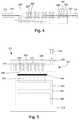
- FIG. 4is a schematic side view of one embodiment of the lead of FIG. 2 coupled to the lead extension of FIG. 3 , according to the invention
- FIG. 5is a schematic side view of one embodiment of a control module suitable for receiving either the lead of FIG. 2 or the lead extension of FIG. 3 , according to the invention
- FIG. 6is a schematic side view of one embodiment of an elongated member retained by the control module of FIG. 5 , according to the invention.
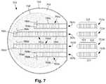
- FIG. 7is a schematic top view of one embodiment of a control module with connector shells extending within a housing of the control module and forming a sealed cavity therewith, and portions of elongated members suitable for insertion into the connector shells, according to the invention;
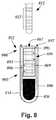
- FIG. 8is a schematic longitudinal cross-sectional view of another embodiment of a control module with a connector shell extending within a housing of the control module and forming a sealed cavity therewith, and a portion of an elongated member suitable for insertion into the connector shell, according to the invention;
- FIG. 9Ais a schematic perspective view of one embodiment of an elongated member disposed in a connector shell with interconnect conductors electrically coupled to connector contacts within the connector shell via interconnect apertures defined along a sidewall of a connector shell, according to the invention
- FIG. 9Bis a schematic perspective view of one embodiment of the elongated member of FIG. 9A disposed in a longitudinal cross-sectional view of the connector assembly of FIG. 9A , according to the invention;
- FIG. 9Cis a close-up view of a portion of the schematic perspective view of one embodiment of the elongated member of FIG. 9B disposed in the longitudinal cross-sectional view of the connector assembly of FIG. 9B , according to the invention;
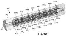
- FIG. 9Dis a schematic perspective, longitudinal cross-sectional view of one embodiment of the connector assembly of FIGS. 9A-9C , according to the invention.
- FIG. 10Ais a schematic perspective, exploded view of one embodiment of a stack of alternating rings of electrically conductive material and electrically nonconductive material, according to the invention.
- FIG. 10Bis a schematic perspective view of one embodiment of the alternating rings of FIG. 10A coupled together to form a connector shell with an elongated shape that is open on one end and defines a lumen suitable for receiving an elongated member, according to the invention;
- FIG. 10Cis a perspective longitudinal cross-sectional view of one embodiment of the connector shell of FIG. 10B , according to the invention.
- FIGS. 11A-11Bare schematic perspective views of one embodiment of a portion of an elongated member disposed in a longitudinal cross-sectional view of a connector shell formed from alternating rings of electrically conductive material and electrically nonconductive material, according to the invention.
- FIG. 12is a schematic overview of one embodiment of components of a stimulation system, including an electronic subassembly disposed within a control module, according to the invention.
- the present inventionis directed to the area of implantable electrical stimulation systems and methods of making and using the systems.
- the present inventionis also directed to systems and methods for providing a connector that extends into a housing of a control module of an electrical stimulation system and becomes part of a sealed cavity therewith, as well as methods of making and using the connector, control modules, and electrical stimulation systems.
- Suitable implantable electrical stimulation systemsinclude, but are not limited to, a least one lead with one or more electrodes disposed on a distal portion of the lead and one or more terminals disposed on one or more proximal portions of the lead.
- Leadsinclude, for example, percutaneous leads, paddle leads, cuff leads, or any other arrangement of electrodes on a lead. Examples of electrical stimulation systems with leads are found in, for example, U.S. Pat. Nos.
- 2007/01500362009/0187222; 2009/0276021; 2010/0076535; 2010/0268298; 2011/0005069; 2011/0004267; 2011/0078900; 2011/0130817; 2011/0130818; 2011/0238129; 2011/0313500; 2012/0016378; 2012/0046710; 2012/0071949; 2012/0165911; 2012/0197375; 2012/0203316; 2012/0203320; 2012/0203321; 2012/0316615; 2013/0105071; and 2013/0197602, all of which are incorporated by reference.
- a percutaneous leadwill be exemplified, but it will be understood that the methods and systems described herein are also applicable to paddle leads and other leads.
- a percutaneous lead for electrical stimulation(for example, deep brain, spinal cord, peripheral nerve, or cardiac-tissue stimulation) includes stimulation electrodes that can be ring electrodes, segmented electrodes that extend only partially around the circumference of the lead, or any other type of electrode, or any combination thereof.
- the segmented electrodescan be provided in sets of electrodes, with each set having electrodes circumferentially distributed about the lead at a particular longitudinal position.
- a set of segmented electrodescan include any suitable number of electrodes including, for example, two, three, four, or more electrodes.
- the leadsare described herein relative to use for deep brain stimulation, but it will be understood that any of the leads can be used for applications other than deep brain stimulation, including spinal cord stimulation, peripheral nerve stimulation, dorsal root ganglion stimulation, sacral nerve stimulation, or stimulation of other nerves, muscles, and tissues.
- an electrical stimulation system 10includes one or more stimulation leads 12 and an implantable pulse generator (IPG) 14 .
- the system 10can also include one or more of an external remote control (RC) 16 , a clinician's programmer (CP) 18 , an external trial stimulator (ETS) 20 , or an external charger 22 .
- RCremote control
- CPclinician's programmer
- ETSexternal trial stimulator
- the IPG 14is physically connected, optionally, via one or more lead extensions 24 , to the stimulation lead(s) 12 .
- Each leadcarries multiple electrodes 26 arranged in an array.
- the IPG 14includes pulse generation circuitry that delivers electrical stimulation energy in the form of, for example, a pulsed electrical waveform (i.e., a temporal series of electrical pulses) to the electrode array 26 in accordance with a set of stimulation parameters.
- the implantable pulse generatorcan be implanted into a patient's body, for example, below the patient's clavicle area or within the patient's buttocks or abdominal cavity.
- the implantable pulse generatorcan have eight stimulation channels which may be independently programmable to control the magnitude of the current stimulus from each channel.
- the implantable pulse generatorcan have more or fewer than eight stimulation channels (e.g., 4-, 6-, 16-, 32-, or more stimulation channels).
- the implantable pulse generatorcan have one, two, three, four, or more connector ports, for receiving the terminals of the leads and/or lead extensions.
- the ETS 20may also be physically connected, optionally via the percutaneous lead extensions 28 and external cable 30 , to the stimulation leads 12 .
- the ETS 20which may have similar pulse generation circuitry as the IPG 14 , also delivers electrical stimulation energy in the form of, for example, a pulsed electrical waveform to the electrode array 26 in accordance with a set of stimulation parameters.
- One difference between the ETS 20 and the IPG 14is that the ETS 20 is often a non-implantable device that is used on a trial basis after the neurostimulation leads 12 have been implanted and prior to implantation of the IPG 14 , to test the responsiveness of the stimulation that is to be provided. Any functions described herein with respect to the IPG 14 can likewise be performed with respect to the ETS 20 .
- the RC 16may be used to telemetrically communicate with or control the IPG 14 or ETS 20 via a uni- or bi-directional wireless communications link 32 . Once the IPG 14 and neurostimulation leads 12 are implanted, the RC 16 may be used to telemetrically communicate with or control the IPG 14 via a uni- or bi-directional communications link 34 . Such communication or control allows the IPG 14 to be turned on or off and to be programmed with different stimulation parameter sets. The IPG 14 may also be operated to modify the programmed stimulation parameters to actively control the characteristics of the electrical stimulation energy output by the IPG 14 .
- the CP 18allows a user, such as a clinician, the ability to program stimulation parameters for the IPG 14 and ETS 20 in the operating room and in follow-up sessions. Alternately, or additionally, stimulation parameters can be programed via wireless communications (e.g., Bluetooth) between the RC 16 (or external device such as a hand-held electronic device) and the IPG 14 .
- wireless communicationse.g
- the CP 18may perform this function by indirectly communicating with the IPG 14 or ETS 20 , through the RC 16 , via a wireless communications link 36 . Alternatively, the CP 18 may directly communicate with the IPG 14 or ETS 20 via a wireless communications link (not shown).
- the stimulation parameters provided by the CP 18are also used to program the RC 16 , so that the stimulation parameters can be subsequently modified by operation of the RC 16 in a stand-alone mode (i.e., without the assistance of the CP 18 ).
- control moduleis used herein to describe a pulse generator (e.g., the IPG 14 or the ETS 20 of FIG. 1 ). Stimulation signals generated by the control module are emitted by electrodes of the lead(s) to stimulate patient tissue.
- the electrodes of the lead(s)are electrically coupled to terminals of the lead(s) that, in turn, are electrically coupleable with the control module.
- the lead(s)couple(s) directly with the control module.
- one or more intermediary devicese.g., a lead extension, an adaptor, a splitter, or the like are disposed between the lead(s) and the control module.
- Percutaneous leadsare described herein for clarity of illustration. It will be understood that paddle leads and cuff leads can be used in lieu of, or in addition to, percutaneous leads.
- the leads described hereininclude 8 electrodes (+1 auxiliary electrode in some embodiments). It will be understood that the leads could include any suitable number of electrodes.
- the leads described hereinexclusively include ring electrodes. It will be understood that the leads can include a distal-tip electrode, or one or more segmented electrodes in lieu of, or in addition to one or more ring electrodes.
- the term “elongated member” used hereinincludes leads (e.g., percutaneous, paddle, cuff, or the like), as well as intermediary devices (e.g., lead extensions, adaptors, splitters, or the like).
- FIG. 2shows, in schematic side view, one embodiment of a lead 212 suitable for implanting into a patient and providing electrical stimulation.
- the lead 212is coupled directly to a control module.
- the lead 212is coupled to the control module via one or more intermediary devices.
- an array of electrodes 226which includes electrode 226 ′, is disposed along a distal portion of a lead body 206 lead and an array of lead terminals 227 , which includes lead terminal 227 ′, is disposed along a proximal portion of the lead body.
- Lead conductors, such as lead conductor 231extend along a longitudinal length of the lead and electrically couple the array of electrodes 226 to the array lead terminals 227 .
- Conductorscan extend along the longitudinal length of the lead within one or more lumens defined in the lead. In other instances, the conductors may extend along the lead within the lead body itself.
- the lead 212includes an auxiliary terminal 208 disposed along the proximal portion of the body to facilitate coupling of the proximal portion of the lead to a connector.
- the connectormay be disposed along a control module.
- the auxiliary terminal 208can be used to facilitate coupling of the proximal portion of the lead to a connector of an intermediary device, such as a lead extension which, in turn, is coupled to a connector of a control module.
- FIG. 3shows, in schematic side view, one embodiment of a lead extension 312 suitable for implanting into a patient and coupling a lead, such as the lead 212 , to a control module.
- the lead extension 312includes a lead-extension body 306 having a distal portion and a proximal portion.
- a lead-extension connector 390is disposed along the distal portion of the lead-extension body 306 and an array of lead-extension terminals 327 , such as lead-extension terminal 327 ′, are disposed along the proximal portion of the lead-extension body 306 .
- the lead-extension connector 390contains a lead-extension connector stack 365 that defines a connector lumen 367 configured to receive the proximal portion of an elongated member (e.g., lead 212 ).
- the lead-extension connector stack 365includes lead-extension connector contacts, such as lead-extension connector contact 369 , arranged along the connector lumen 367 and configured to electrically couple with terminals of the elongated member (e.g., lead 212 ) when the proximal portion of the elongated member is received by the lead-extension connector 390 .
- the connector contactscan be electrically isolated from one another by electrically-nonconductive spacers, such as spacer 371 .
- the connector stackmay also include an end stop 373 to promote alignment of the elongated-member terminals with the lead-extension connector contacts.
- the lead-extension connector 390further includes a retention assembly for facilitating retention of the proximal portion of the elongated member (e.g., lead 212 ) when the proximal portion of the elongated member is received by the lead-extension connector 390 .
- the retention assemblyincludes a lead-extension retention block 392 .
- the lead-extension retention block 392is positioned to align with the auxiliary terminal ( 208 in FIG. 2 ) of the elongated member when the elongated member is received by the lead-extension connector 390 .
- the retention assemblyfurther includes a retaining member (e.g., a set screw, a pin, or the like) 394 for pressing the auxiliary terminal of the inserted elongated member against the retention block to retain inserted elongated member within the lead-extension connector 390 .
- a retaining membere.g., a set screw, a pin, or the like
- Lead-extension conductorssuch as lead-extension conductor 331 , extend along a longitudinal length of the lead extension and electrically couple the lead-extension connector contacts to the array of lead-extension terminals 327 .
- the lead-extension conductorscan extend along the longitudinal length of the lead-extension body within one or more lumens defined in the lead extension. In other instances, the lead-extension conductors may extend along the lead extension within the lead-extension body itself.
- the lead extension 312includes an auxiliary terminal 308 disposed along the proximal portion of the lead-extension body to facilitate coupling of the proximal portion of the lead extension to a connector, such as a control-module connector, another lead-extension connector, or the like.
- FIG. 4shows, in schematic side view, one embodiment of the lead 212 received by the lead-extension connector 390 .
- the lead terminals 227such as lead terminal 227 ′, are aligned with the lead-extension connector contacts, such as lead-extension connector contact 369 .
- the lead conductors 231are electrically coupled with the lead-extension conductors 331 .
- the lead auxiliary terminal 208is aligned with the lead-extension retention block 392 and the retaining member 394 is pressing the lead auxiliary terminal 208 against the lead-extension retention block to retain the lead 212 within the lead-extension connector 390 .
- FIG. 5shows, in schematic cross-sectional side view, a control module 552 suitable for coupling with an elongated member (e.g., the lead 212 , the lead extension 312 , or other intermediary device).
- the control module 552includes a header 553 disposed along an outer surface of a sealed housing 554 that contains an electronic subassembly 558 with a pulse generator 514 and, optionally, a power supply 560 .
- a connector assembly 590is disposed in the header 553 .
- the connector assembly 590is configured to receive an elongated device (e.g., the lead 212 , the lead extension 312 , or other intermediary device).
- the connector assembly 590defines a connector lumen 567 configured to receive the proximal portion of the elongated member.
- An array of connector contacts, such as connector contact 569is arranged along the connector lumen 567 and configured to electrically couple with terminals of the elongated member when the proximal portion of the elongated member is received by the connector 590 .
- the connector contactscan be electrically isolated from one another by electrically-nonconductive spacers, such as spacer 571 .
- the connector stackmay also include an end stop 573 to promote alignment of the elongated-member terminals with the connector contacts.
- Feedthrough interconnectssuch as feedthrough interconnect 582 are electrically coupled to the electrical subassembly 558 and extend within the sealed housing 554 to a feedthrough interface 586 disposed along an interface between the header 553 and the sealed housing 554 .
- the connector contactsare electrically coupled to interconnect conductors, such as interconnect wire 580 , that extend along the header 553 and electrically couple the connector contacts to the feedthrough interconnects at the feedthrough interface 586 .
- the header 553is positioned over the feedthrough interface 586 .
- the connector assembly 590optionally, includes a retention assembly for facilitating retention of the proximal portion of the elongated member when the proximal portion of the elongated member is received by the control module 552 .
- the retention assemblyincludes a retention block 592 .
- the retention block 592is positioned to align with a retention sleeve (see e.g., 608 in FIG. 6 ) of the elongated member when the elongated member is received by the connector assembly 590 .
- the retention assemblyfurther includes a retaining member (e.g., a set screw, a pin, or the like) 594 for pressing the retention sleeve of the inserted elongated member against the retention block to retain inserted elongated member within the connector assembly 590 .
- a retaining membere.g., a set screw, a pin, or the like
- FIG. 6shows, in schematic side view, one embodiment of an elongated member 612 (e.g., the lead 212 , the lead extension 312 , or other intermediary device) received by the connector assembly 590 of the control module 552 .
- the elongated-member terminalssuch as elongated-member terminal 627
- the connector contactssuch as connector contact 569 .
- the elongated-member conductors 631are electrically coupled with the interconnect conductors 580 and feedthrough interconnects 582 .
- a retention sleeve 608 disposed along the elongated member 612is aligned with the retention block 592 and the retaining member 594 is pressing the retention sleeve 608 against the retention block 592 to retain the elongated member 612 within the connector assembly 590 .
- Connector assembliesare often disposed within headers disposed over sealed housings containing an electronic subassembly (e.g., the IPG).
- an electronic subassemblye.g., the IPG
- Conventional headersare unsealed and are typically formed using casting techniques.
- Interconnect conductors used to electrically couple connector contacts with the electronic subassemblyare often arranged along the header in complicated wiring configurations encased in epoxy. Interconnect conductors cannot typically couple the connector contacts directly to the electronic subassembly because the header is positioned external to the sealed housing. Instead, the interconnect conductors typically couple the connector contacts to feedthrough interconnects that extend from the electronic subassembly to a feedthrough interface positioned along an outer surface of the sealed housing.
- Connector assemblies formed along unsealed, or non-hermetic, portions of control modulesmay include locations prone to undesired current leakage. Many such potential locations occur along portions of the interconnect conductors. For example, current leakage can occur along portions of interconnect conductors where the interconnect conductors couple with feedthrough interconnects at the feedthrough interface; between two or more non-insulated interconnect conductors; at the interface between the interconnect conductors and the connector contacts; and along portions of interconnect conductors breaching outer surfaces of the casted header.
- the connector assemblyincludes a connector shell that is hermetically, or near-hermetically, sealed.
- the connector shellcan be disposed in a header (e.g., header 553 of FIG. 5 ), it does not need to be.
- control modules within which the connector shells are disposeddo not include headers.
- the interconnect conductorsextend from the one or more connector shells within the sealed housing of the control module. Accordingly, the interconnect conductors do not need to be formed from noble metals or be encased in epoxy. In at least some embodiments, utilizing the connector shells reduces the amount of, or even eliminates, epoxy used in the connector. In at least some embodiments, the connector shell enables interconnect conductors to directly couple connector contacts to the electronic subassembly of the control module, thereby eliminating the need for feedthrough interconnects.
- FIG. 7illustrates, in schematic top view, a control module 752 suitable for implanting into a patient and coupling to an electrical stimulation lead.
- the control module 752includes an electronic subassembly 758 disposed in a sealed cavity 753 of a housing 754 .
- the control modulefurther includes one or more connector assemblies for receiving one or more elongated members (e.g., leads or lead extensions) and electrically coupling terminals of a received elongated member to the electronic subassembly 758 .
- the control module 752is shown with four connector assemblies 791 a - d.
- the connector assemblieseach include at least one connector contact arranged along a connector lumen defined in a connector shell.
- the connector shell(s)extend(s) into the housing 754 .
- the connector shell(s), along with the housing 754collectively form the sealed cavity 753 .
- connector assembly 791 aincludes connector contacts, such as connector contact 769 a , arranged along connector lumen 767 a defined in a connector shell 793 a ;
- connector assembly 791 bincludes connector contacts, such as connector contact 769 b , arranged along connector lumen 767 b defined in a connector shell 793 b ;
- connector assembly 791 cincludes connector contacts, such as connector contact 769 c , arranged along connector lumen 767 c defined in a connector shell 793 c ;
- connector assembly 791 dincludes connector contacts, such as connector contact 769 d , arranged along connector lumen 767 d defined in a connector shell 793 d.
- the connector assembliescan be configured for receiving elongated members with different numbers of terminals including, for example, 1, 2, 4, 8, 12, 16, 24, or more terminals. Additionally, different numbers of connector assemblies can be disposed in the control module including, for example, one, two, three, four, six, eight, or more connector assemblies.
- the connector assemblies 791 a , 791 beach include eight connector contacts. Accordingly, the connector assemblies 791 a , 791 b are each configured to receive elongated members 712 a , 712 b , respectively, each having eight terminals 727 .
- the connector assemblies 791 c , 791 deach include sixteen connector contacts. Accordingly, the connector assemblies 791 c , 791 d are each configured to receive elongated members 712 c , 712 d , respectively, each having sixteen terminals 727 .
- Interconnect conductorselectrically couple the connector contacts to the electronic subassembly 758 .
- interconnect wire 780 aelectrically couples connector contact 769 a to the electronic subassembly 758 ;
- interconnect wire 780 belectrically couples connector contact 769 b to the electronic subassembly 758 ;
- interconnect wire 780 celectrically couples connector contact 769 c to the electronic subassembly 758 ;
- interconnect wire 780 delectrically couples connector contact 769 d to the electronic subassembly 758 .
- each connector contact of each connector assemblyis coupled to the electronic subassembly.
- each connector contactis coupled to the electronic subassembly via a different interconnect wire that extends from the connector shell to the electronic subassembly within the sealed cavity 753 .
- the control modulecan be formed in any suitable arrangement to accommodate the components of the control module including, for example, the connector shell(s), the electronic subassembly, and the electrical connections extending therebetween.
- FIG. 8illustrates, in schematic longitudinal cross-sectional view, another embodiment of a control module 852 suitable for implanting into a patient and coupling to an electrical stimulation lead.
- the control module 852includes an electronic subassembly 858 disposed in a sealed housing 854 .
- the control modulefurther includes a connector assembly for receiving an elongated member (e.g., a lead or lead extension) and electrically coupling terminals of the received elongated member to the electronic subassembly 858 .
- the control module 852is shown with a single connector assembly 891 .
- the connector assembly 891includes connector contacts, such as connector contact 869 , arranged along connector lumen 867 defined in connector shell 893 .
- the connector assembly 891includes four connector contacts and is configured to receive an elongated member 812 with four terminals 827 .
- the connector shell 893has an elongated shape with a first end 804 , an opposing second end 805 , and a sidewall 806 .
- the first end 804 of the connector shellis open to receive the elongated member.
- the illustrated embodimentshows an optional flange 895 disposed along the open first end 804 of the of the connector shell 893 .
- the flange 895may be useful for facilitating insertion of the elongated member into the connector shell.
- the flange 895can be attached to the connector shell using any suitable technique (e.g., brazing, welding, co-firing, or the like).
- a hermetic weld 897is formed around a perimeter of the first end 804 of the connector shell 893 (or a perimeter of the flange, if applicable) to seal the connector shell 893 with the housing 854 .
- the connector assemblyincludes a strain relief disposed in proximity to the open first end 804 of the connector shell.
- the connector assemblyincludes a retention assembly (see e.g., retention block 592 and retaining member 594 of FIG. 5 ) for facilitating retention of the elongated member when the elongated member is received by the connector assembly.
- the connector assemblyis closed at the second end 805 .
- the connector assemblyincludes an end stop (see e.g., end stop 573 of FIG. 5 ) disposed along the second end 805 of the connector shell 893 .
- control modulesare formed to receive a single elongated member, or multiple elongated members each having the same number of terminals.
- FIG. 7in embodiments where multiple connector shells are utilized, and where the connector shells include different numbers of connector contacts, longer connector lumens may be needed to accommodate the connector shells with the comparatively higher numbers of connector contacts. It may be advantageous to arrange comparatively longer-lumened connector shells medial to shorter-lumened connector shells to increase efficiency of size when the housing 754 has rounded shape, as is shown in FIG. 7 .
- the connector shellsare oriented relative to the electronic subassembly such that the electronic subassembly is in proximity to the sidewalls of the connector shells.
- the connector shellis oriented relative to the electronic subassembly such that the electronic subassembly is in proximity to the second end 805 of the connector shell.
- the orientation of the connector shell relative to the electronic subassemblycan be modified to enable the shape of the control module to accommodate the positioning of implantation, or ease of use, or other purposes or reasons.
- the connector shellis formed from an electrically nonconductive material including, for example, glass, ceramic(s), or combinations thereof.
- the connector shellis open at one end and closed at an opposing end.
- the connector shellis formed as a tube.
- the connector shelldefines one or more interconnect apertures along the sidewall (longitudinal length) of the connector shell.
- the interconnect aperturesfacilitate electrical coupling of the connector contacts to the electronic subassembly by interconnect conductors.
- the interconnect aperturescan be hermetically sealed using either electrically conductive material (e.g., solder, cermet, or the like), or electrically nonconductive material (e.g., glass or ceramic).
- the interconnect aperturesare sealed using vias electrically coupled to the connector contacts.
- the viasare formed after the interconnect conductors are extended through the interconnector apertures and electrically coupled to connector contacts.
- the viasare formed before the interconnect conductors are coupled to the connector contacts, and the interconnect conductors electrically couple to the connector contacts by electrically coupling to the vias.
- the viasare brazed to walls of the interconnect apertures. In other embodiments, the vias are welded to walls of the interconnect apertures.
- FIG. 9Ashows, in schematic perspective view, an elongated member 912 (e.g., a lead or a lead extension) disposed in a connector assembly 991 .
- FIG. 9Bshows the connector assembly 991 in longitudinal cross-sectional view.
- FIG. 9Cshows a portion of the elongated member 912 disposed in a portion of the connector assembly 991 in close-up view.
- FIG. 9Dshows the connector assembly 991 in perspective, longitudinal cross-sectional view without the elongated member 912 disposed in the connector assembly 991 .
- the connector assembly 991includes connector contacts 869 a - h disposed in a connector lumen 967 of a connector shell 993 .
- the connector contacts 869 a - hare physically and electrically isolated from one another by electrically nonconductive spacers 971 a - h .
- Interconnect conductors 880 a - helectrically couple with the connector contacts 869 a - h , respectively, via interconnect apertures 999 a - h , respectively, defined along a sidewall 906 of the connector shell 993 .
- each interconnect wireextends through a different interconnect aperture.
- multiple interconnect conductorsextend through at least one of the interconnect apertures.
- the interconnect conductorscan, in some embodiments, be electrically coupled directly to the connector contacts using any suitable technique (e.g., laser welding).
- the interconnect aperturescan be hermetically sealed before or after the interconnect conductors are electrically-coupled to the connector contacts.
- the interconnect aperturesare sealed using a hermetic sealing material including, for example, metal (e.g., solder, cermet, or the like), glass, or ceramic.
- electrically conductive sealing materiale.g., vias
- the interconnector conductorscan, optionally, be coupled to the connector contacts indirectly by electrically coupling to the vias.
- one or more of the connector contacts, interconnect conductors, and interconnect apertures surfacesare coated with one or more materials in preparation for accepting the hermetic sealing material. In at least some embodiments, one or more of the connector contacts, interconnect conductors, and interconnect apertures surfaces are preheated prior to application of the hermetic sealing material.
- the connector contactscan be formed from any electrically-conductive material suitable for implantation.
- the connector contactscan be formed in any suitable configuration to make electrical contact with terminals of a received elongated member.
- the connector contactsare formed as leaf springs.
- the connector shellis formed from sections of electrically conductive material interconnected with sections of electrically nonconductive material fixedly attached together.
- the interconnected sections of materialare stacked along a longitudinal length of the connector shell.
- the interconnected sections of materialare arranged in an alternating conductive-nonconductive configuration.
- the interconnected sections of materialare formed as alternating rings of material.
- FIG. 10Aillustrates, in schematic perspective, explosive view, a stack of ring-shaped sections of electrically conductive material 1014 a - d alternated with ring-shaped sections of electrically nonconductive material 1016 a - e .
- FIG. 10Bshows the alternating ring-shaped sections 1014 a - d and 1016 a - e interconnected to form a connector shell 1093 having a first end 1004 , an opposing second end 1005 , and a longitudinal length (indicated by two-headed arrow 1006 ).
- FIG. 10Cshows the connector shell 1093 in longitudinal cross-sectional view.
- the alternating ring-shaped sections 1014 a - d and 1016 a - eeach define a central aperture, such as central aperture 1020 .
- the central apertures 1020align to collectively form a connector lumen 1067 that is open at the first end 1004 of the connector shell 1004 .
- the illustrated embodimentincludes an optional end piece 1073 disposed along the second end 1005 of the connector shell 1093 .
- the optional end piece 1073functions to close the second end 1005 of the connector shell 1004 .
- the end piece 1073is formed from electrically nonconductive material.
- An optional flange 1095can be coupled to the first end 1004 of the connector shell 1093 to facilitate insertion of an elongated member into the connector lumen 1067 .
- the interconnected ring-shaped sections 1014 a - d and 1016 a - fcan be interconnected using any suitable technique including, for example, brazing, 3D printing, co-firing (low- or high-temperature).
- the optional flange 1095can be coupled to the connector shell 1093 using any suitable technique including, for example, brazing, 3D printing, co-firing (low- or high-temperature).
- the ring-shaped sections (and the end piece and the flange, if applicable)are interconnected to form a hermetic seal along the sidewall (longitudinal length) and the second end of the connector shell.
- the ring-shaped sectionsare arranged such that each of the electrically conductive ring-shaped sections 1014 a - d is separated from each of the remaining electrically conductive ring-shaped sections 1014 a - d by at least one electrically nonconductive ring-shaped section 1016 a - e in either direction along the longitudinal length 1006 of the connector shell 1093 .
- FIGS. 11A-11Bshow, in perspective view, a portion of an elongated member 1112 disposed in a connector assembly 1171 (shown in longitudinal cross-section).
- the connector assembly 1191includes a connector shell 1193 having a first end 1104 and an opposing second end 1105 , and is formed from ring-shaped sections of electrically conductive material 1114 a - h arranged in an alternating configuration with ring-shaped sections of electrically nonconductive material 1116 a - h .
- Connector contacts 1169 a - hare disposed in a connector lumen 1167 of the connector shell 1193 .
- the connector contacts 1169 a - hare physically and electrically isolated from one another within the connector lumen 1167 by spacers 1171 a - h.
- the alternating ringscan be aligned along the longitudinal length of the connector shell 1193 with corresponding connector contacts and spacers.
- the electrically conductive rings 1114 a - hare aligned along the longitudinal length of the connector shell 1193 with the connector contacts 1169 a - h , respectively.
- the electrically conductive rings 1114 a - hare electrically coupled to the connector contacts 1169 a - h , respectively, to which they are longitudinally aligned.
- the electrically nonconductive rings 1116 a - hare aligned along the longitudinal length of the connector shell 1193 with the spacers 1171 a - h.
- one or more interconnect aperturesare defined along sidewalls of the connector shell 1193 to facilitate electrical coupling of interconnect conductors to the connector contacts.
- interconnect apertures 1199 a - hare defined along sidewalls of the electrically conductive rings 1114 a - h .
- the interconnect apertures 1199 a - hare suitable for enabling interconnect conductors (not shown in FIGS. 11A-11B ) to electrically couple with the connector contacts 1169 a - h , as described above with reference to FIGS. 9A-9D .
- interconnect conductorsare electrically coupleable to connector contacts 1169 a - h by coupling the interconnect conductors to a cavity-facing surface (see e.g., FIG. 7 ) of the electrically conductive rings aligned with, and electrically coupled to, the connector contacts.
- an interconnect conductoris electrically coupleable to connector contact 1169 a by electrically coupling the interconnect wire to a cavity-facing surface of the electrically conductive ring 1114 a which, in turn, is electrically coupled to the connector contact 1169 a .
- the interconnect conductorextends entirely within the sealed cavity of the control module.
- FIGS. 11A-11Bshow a portion of an optional retention block 1192 formed along the first end 1104 of the connector shell 1193 .
- the retention block 1192may be used to facilitate retention of the elongated member 1112 in the connector assembly 1191 .
- the second end 1106 of the connector shellis closed.
- FIGS. 11A-11Balso show an optional end stop 1173 disposed along the second end 1106 of the connector shell 1193 .
- the ring-shaped sections and end pieceare interconnected to form a hermetic seal along the sidewall (longitudinal length) and second end of the connector shell.
- FIG. 12is a schematic overview of one embodiment of components of an electrical stimulation system 1200 including an electronic subassembly 1258 disposed within a control module.
- the electronic subassembly 1258may include one or more components of the IPG. It will be understood that the electrical stimulation system can include more, fewer, or different components and can have a variety of different configurations including those configurations disclosed in the stimulator references cited herein.
- a power source 1212can be used including, for example, a battery such as a primary battery or a rechargeable battery.
- a batterysuch as a primary battery or a rechargeable battery.
- other power sourcesinclude super capacitors, nuclear or atomic batteries, mechanical resonators, infrared collectors, thermally-powered energy sources, flexural powered energy sources, bioenergy power sources, fuel cells, bioelectric cells, osmotic pressure pumps, and the like including the power sources described in U.S. Pat. No. 7,437,193, incorporated herein by reference.
- powercan be supplied by an external power source through inductive coupling via the optional antenna 1218 or a secondary antenna.
- the antenna 1218(or the secondary antenna) is implemented using the auxiliary electrically-conductive conductor.
- the external power sourcecan be in a device that is mounted on the skin of the user or in a unit that is provided near the user on a permanent or periodic basis.
- the batterymay be recharged using the optional antenna 1218 , if desired. Power can be provided to the battery for recharging by inductively coupling the battery through the antenna to a recharging unit 1216 external to the user. Examples of such arrangements can be found in the references identified above.
- the electronic subassembly 1258 and, optionally, the power source 1212can be disposed within a control module (e.g., the IPG 14 or the ETS 20 of FIG. 1 ).
- electrical stimulation signalsare emitted by the electrodes (e.g., 26 in FIG. 1 ) to stimulate nerve fibers, muscle fibers, or other body tissues near the electrical stimulation system.
- the processor 1204is generally included to control the timing and electrical characteristics of the electrical stimulation system. For example, the processor 1204 can, if desired, control one or more of the timing, frequency, strength, duration, and waveform of the pulses. In addition, the processor 1204 can select which electrodes can be used to provide stimulation, if desired. In some embodiments, the processor 1204 selects which electrode(s) are cathodes and which electrode(s) are anodes. In some embodiments, the processor 1204 is used to identify which electrodes provide the most useful stimulation of the desired tissue.
- Any processorcan be used and can be as simple as an electronic device that, for example, produces pulses at a regular interval or the processor can be capable of receiving and interpreting instructions from an external programming unit 1208 that, for example, allows modification of pulse characteristics.
- the processor 1204is coupled to a receiver 1202 which, in turn, is coupled to the optional antenna 1218 . This allows the processor 1204 to receive instructions from an external source to, for example, direct the pulse characteristics and the selection of electrodes, if desired.
- the antenna 1218is capable of receiving signals (e.g., RF signals) from an external telemetry unit 1206 which is programmed by the programming unit 1208 .
- the programming unit 1208can be external to, or part of, the telemetry unit 1206 .
- the telemetry unit 1206can be a device that is worn on the skin of the user or can be carried by the user and can have a form similar to a pager, cellular phone, or remote control, if desired.
- the telemetry unit 1206may not be worn or carried by the user but may only be available at a home station or at a clinician's office.
- the programming unit 1208can be any unit that can provide information to the telemetry unit 1206 for transmission to the electrical stimulation system 1200 .
- the programming unit 1208can be part of the telemetry unit 1206 or can provide signals or information to the telemetry unit 1206 via a wireless or wired connection.
- One example of a suitable programming unitis a computer operated by the user or clinician to send signals to the telemetry unit 1206 .
- the signals sent to the processor 1204 via the antenna 1218 and the receiver 1302can be used to modify or otherwise direct the operation of the electrical stimulation system.
- the signalsmay be used to modify the pulses of the electrical stimulation system such as modifying one or more of pulse duration, pulse frequency, pulse waveform, and pulse strength.
- the signalsmay also direct the electrical stimulation system 1200 to cease operation, to start operation, to start charging the battery, or to stop charging the battery.
- the stimulation systemdoes not include the antenna 1218 or receiver 1202 and the processor 1204 operates as programmed.
- the electrical stimulation system 1200may include a transmitter (not shown) coupled to the processor 1204 and the antenna 1218 for transmitting signals back to the telemetry unit 1206 or another unit capable of receiving the signals.
- the electrical stimulation system 1200may transmit signals indicating whether the electrical stimulation system 1200 is operating properly or not or indicating when the battery needs to be charged or the level of charge remaining in the battery.
- the processor 1204may also be capable of transmitting information about the pulse characteristics so that a user or clinician can determine or verify the characteristics.
Landscapes
- Health & Medical Sciences (AREA)
- Public Health (AREA)
- Engineering & Computer Science (AREA)
- Nuclear Medicine, Radiotherapy & Molecular Imaging (AREA)
- Radiology & Medical Imaging (AREA)
- Life Sciences & Earth Sciences (AREA)
- Animal Behavior & Ethology (AREA)
- Biomedical Technology (AREA)
- Veterinary Medicine (AREA)
- General Health & Medical Sciences (AREA)
- Electrotherapy Devices (AREA)
- Neurology (AREA)
- Neurosurgery (AREA)
- Orthopedic Medicine & Surgery (AREA)
- Cardiology (AREA)
- Heart & Thoracic Surgery (AREA)
Abstract
Description
Claims (20)
Priority Applications (1)
| Application Number | Priority Date | Filing Date | Title |
|---|---|---|---|
| US16/041,355US10918873B2 (en) | 2017-07-25 | 2018-07-20 | Systems and methods for making and using an enhanced connector of an electrical stimulation system |
Applications Claiming Priority (2)
| Application Number | Priority Date | Filing Date | Title |
|---|---|---|---|
| US201762536839P | 2017-07-25 | 2017-07-25 | |
| US16/041,355US10918873B2 (en) | 2017-07-25 | 2018-07-20 | Systems and methods for making and using an enhanced connector of an electrical stimulation system |
Publications (2)
| Publication Number | Publication Date |
|---|---|
| US20190030345A1 US20190030345A1 (en) | 2019-01-31 |
| US10918873B2true US10918873B2 (en) | 2021-02-16 |
Family
ID=63143391
Family Applications (1)
| Application Number | Title | Priority Date | Filing Date |
|---|---|---|---|
| US16/041,355Active2039-04-11US10918873B2 (en) | 2017-07-25 | 2018-07-20 | Systems and methods for making and using an enhanced connector of an electrical stimulation system |
Country Status (3)
| Country | Link |
|---|---|
| US (1) | US10918873B2 (en) |
| EP (1) | EP3658228A1 (en) |
| WO (1) | WO2019023067A1 (en) |
Cited By (2)
| Publication number | Priority date | Publication date | Assignee | Title |
|---|---|---|---|---|
| US12357792B2 (en) | 2019-01-04 | 2025-07-15 | Shifamed Holdings, Llc | Internal recharging systems and methods of use |
| US12440656B2 (en) | 2021-04-23 | 2025-10-14 | Shifamed Holdings, Llc | Power management for interatrial shunts and associated systems and methods |
Families Citing this family (13)
| Publication number | Priority date | Publication date | Assignee | Title |
|---|---|---|---|---|
| US10342983B2 (en) | 2016-01-14 | 2019-07-09 | Boston Scientific Neuromodulation Corporation | Systems and methods for making and using connector contact arrays for electrical stimulation systems |
| US10543374B2 (en) | 2016-09-30 | 2020-01-28 | Boston Scientific Neuromodulation Corporation | Connector assemblies with bending limiters for electrical stimulation systems and methods of making and using same |
| US10905871B2 (en) | 2017-01-27 | 2021-02-02 | Boston Scientific Neuromodulation Corporation | Lead assemblies with arrangements to confirm alignment between terminals and contacts |
| US10814136B2 (en) | 2017-02-28 | 2020-10-27 | Boston Scientific Neuromodulation Corporation | Toolless connector for latching stimulation leads and methods of making and using |
| US10603499B2 (en) | 2017-04-07 | 2020-03-31 | Boston Scientific Neuromodulation Corporation | Tapered implantable lead and connector interface and methods of making and using |
| WO2019023067A1 (en) | 2017-07-25 | 2019-01-31 | Boston Scientific Neuromodulation Corporation | Systems and methods for making and using an enhanced connector of an electrical stimulation system |
| US10639485B2 (en) | 2017-09-15 | 2020-05-05 | Boston Scientific Neuromodulation Corporation | Actuatable lead connector for an operating room cable assembly and methods of making and using |
| US11045656B2 (en) | 2017-09-15 | 2021-06-29 | Boston Scientific Neuromodulation Corporation | Biased lead connector for operating room cable assembly and methods of making and using |
| US11103712B2 (en) | 2018-01-16 | 2021-08-31 | Boston Scientific Neuromodulation Corporation | Connector assemblies with novel spacers for electrical stimulation systems and methods of making and using same |
| US11052259B2 (en) | 2018-05-11 | 2021-07-06 | Boston Scientific Neuromodulation Corporation | Connector assembly for an electrical stimulation system and methods of making and using |
| EP3946569B1 (en) | 2019-04-01 | 2023-11-15 | Boston Scientific Neuromodulation Corporation | Low-profile control module for an electrical stimulation system |
| US11357992B2 (en) | 2019-05-03 | 2022-06-14 | Boston Scientific Neuromodulation Corporation | Connector assembly for an electrical stimulation system and methods of making and using |
| US12343547B2 (en) | 2021-08-19 | 2025-07-01 | Boston Scientific Neuromodulation Corporation | Connectors for an electrical stimulation system and methods of making and using |
Citations (412)
| Publication number | Priority date | Publication date | Assignee | Title |
|---|---|---|---|---|
| US3222471A (en) | 1963-06-10 | 1965-12-07 | Ripley Company Inc | Multiple electrical connector with longitudinal spaced contacts carried by insulating key |
| US3601747A (en) | 1969-09-18 | 1971-08-24 | Singer General Precision | Brush block retractor and alignment device |
| US3718142A (en) | 1971-04-23 | 1973-02-27 | Medtronic Inc | Electrically shielded, gas-permeable implantable electro-medical apparatus |
| US3757789A (en) | 1971-10-26 | 1973-09-11 | I Shanker | Electromedical stimulator lead connector |
| US3771106A (en) | 1971-04-14 | 1973-11-06 | New Nippon Electric Co | Socket suited for revolving the lamp attached thereto |
| US3908668A (en) | 1974-04-26 | 1975-09-30 | Medtronic Inc | Tissue stimulator with sealed lead connector |
| US3951154A (en) | 1974-04-30 | 1976-04-20 | Medtronic, Inc. | Lead connector for electro-medical device |
| US3990727A (en) | 1976-01-26 | 1976-11-09 | Stephen Franics Gallagher | Quick detachable coupler |
| US4003616A (en) | 1975-12-03 | 1977-01-18 | Clairol Incorporated | Swivelling electrical connector |
| US4112953A (en) | 1977-03-11 | 1978-09-12 | Medcor, Inc. | Pacer stimulator with improved lead connector |
| US4142532A (en) | 1978-04-07 | 1979-03-06 | Medtronic, Inc. | Body implantable stimulator with novel connector and method |
| US4180078A (en) | 1978-04-07 | 1979-12-25 | Medtronic, Inc. | Lead connector for a body implantable stimulator |
| US4245642A (en) | 1979-06-28 | 1981-01-20 | Medtronic, Inc. | Lead connector |
| US4259962A (en) | 1979-08-24 | 1981-04-07 | Cordis Corporation | Sealing system for cardiac pacer lead connector |
| US4310001A (en) | 1980-04-21 | 1982-01-12 | Medtronic, Inc. | Connector assembly for body implantable medical systems |
| US4364625A (en) | 1980-06-12 | 1982-12-21 | Bell Telephone Laboratories, Incorporated | Electrical jack assembly |
| US4367907A (en) | 1980-08-04 | 1983-01-11 | Magnetic Controls Company | Circuit monitoring jack |
| US4411277A (en) | 1981-04-28 | 1983-10-25 | Medtronic, Inc. | Implantable connector |
| US4411276A (en) | 1981-04-28 | 1983-10-25 | Medtronic, Inc. | Implantable multiple connector |
| US4461194A (en) | 1982-04-28 | 1984-07-24 | Cardio-Pace Medical, Inc. | Tool for sealing and attaching a lead to a body implantable device |
| US4466441A (en) | 1982-08-02 | 1984-08-21 | Medtronic, Inc. | In-line and bifurcated cardiac pacing lead connector |
| US4516820A (en) | 1983-01-27 | 1985-05-14 | The Commonwealth Of Australia | Cochlear prosthesis package connector |
| US4540236A (en) | 1983-07-18 | 1985-09-10 | Cordis Corporation | Quick lock/quick release connector |
| USRE31990E (en) | 1978-11-22 | 1985-09-24 | Intermedics, Inc. | Multiple function lead assembly and method for inserting assembly into an implantable tissue stimulator |
| US4602624A (en) | 1984-10-11 | 1986-07-29 | Case Western Reserve University | Implantable cuff, method of manufacture, and method of installation |
| US4603696A (en) | 1985-02-14 | 1986-08-05 | Medtronic, Inc. | Lead connector |
| US4614395A (en) | 1985-04-04 | 1986-09-30 | Cordis Corporation | Quick connector to medical electrical lead |
| US4630611A (en) | 1981-02-02 | 1986-12-23 | Medtronic, Inc. | Orthogonally-sensing lead |
| US4695117A (en) | 1985-06-03 | 1987-09-22 | Switchcraft, Inc. | Jack module and jackfield |
| US4695116A (en) | 1984-02-27 | 1987-09-22 | Switchcraft, Inc. | Stacked electrical jacks |
| US4712557A (en) | 1986-04-28 | 1987-12-15 | Cordis Leads, Inc. | A pacer including a multiple connector assembly with removable wedge and method of use |
| US4715380A (en) | 1986-04-03 | 1987-12-29 | Telectronics N.V. | Capped pacer neck containing a connector assembly |
| US4744370A (en) | 1987-04-27 | 1988-05-17 | Cordis Leads, Inc. | Lead assembly with selectable electrode connection |
| US4784141A (en) | 1987-08-04 | 1988-11-15 | Cordis Leads, Inc. | Lead locking mechanism for cardiac pacers |
| US4832032A (en) | 1985-08-16 | 1989-05-23 | La Jolla Technology, Inc. | Electrical apparatus protective interconnect |
| US4840580A (en) | 1987-06-05 | 1989-06-20 | Siemens Ag | Connector arrangement for a lead for an implantable stimulation device |
| US4850359A (en) | 1987-10-16 | 1989-07-25 | Ad-Tech Medical Instrument Corporation | Electrical brain-contact devices |
| US4860750A (en) | 1986-04-17 | 1989-08-29 | Intermedics Inc. | Sidelock pacer lead connector |
| US4867708A (en) | 1986-12-27 | 1989-09-19 | Iizuka Electric Industry Company Limited | Electric jack |
| US4869255A (en) | 1987-12-04 | 1989-09-26 | Ad-Tech Medical Instrument Corp. | Electrical connection device |
| US4898173A (en) | 1988-04-22 | 1990-02-06 | Medtronic, Inc. | In-line pacemaker connector system |
| US4899753A (en) | 1985-10-02 | 1990-02-13 | Fukuda Denshi Co., Ltd. | Electrocardiographic electrode |
| US4934366A (en)* | 1988-09-01 | 1990-06-19 | Siemens-Pacesetter, Inc. | Feedthrough connector for implantable medical device |
| US4951687A (en) | 1989-01-31 | 1990-08-28 | Medtronic, Inc. | Medical electrical lead connector |
| US4995389A (en) | 1985-12-16 | 1991-02-26 | Telectronics Pacing Systems, Inc. | Multielectrode quick connect cardiac pacing lead connector assembly |
| US5000177A (en) | 1990-01-29 | 1991-03-19 | Cardiac Pacemakers, Inc. | Bipolar lead adapter with resilient housing and rigid retainers for plug seals |
| US5000194A (en) | 1988-08-25 | 1991-03-19 | Cochlear Corporation | Array of bipolar electrodes |
| US5007864A (en) | 1989-11-27 | 1991-04-16 | Siemens-Pacesetter, Inc. | Device for adapting a pacemaker lead to a pacemaker |
| US5007435A (en) | 1988-05-25 | 1991-04-16 | Medtronic, Inc. | Connector for multiconductor pacing leads |
| US5070605A (en) | 1988-04-22 | 1991-12-10 | Medtronic, Inc. | Method for making an in-line pacemaker connector system |
| US5082453A (en) | 1991-05-16 | 1992-01-21 | Siemens-Pacesetter, Inc. | Multi-contact connector system for an implantable medical device |
| US5086773A (en) | 1990-09-10 | 1992-02-11 | Cardiac Pacemakers, Inc. | Tool-less pacemaker lead assembly |
| US5135001A (en) | 1990-12-05 | 1992-08-04 | C. R. Bard, Inc. | Ultrasound sheath for medical diagnostic instruments |
| US5193539A (en) | 1991-12-18 | 1993-03-16 | Alfred E. Mann Foundation For Scientific Research | Implantable microstimulator |
| US5193540A (en) | 1991-12-18 | 1993-03-16 | Alfred E. Mann Foundation For Scientific Research | Structure and method of manufacture of an implantable microstimulator |
| US5201865A (en) | 1991-10-28 | 1993-04-13 | Medtronic, Inc. | Medical lead impedance measurement system |
| US5241957A (en) | 1991-11-18 | 1993-09-07 | Medtronic, Inc. | Bipolar temporary pacing lead and connector and permanent bipolar nerve wire |
| US5252090A (en) | 1992-09-30 | 1993-10-12 | Telectronics Pacing Systems, Inc. | Self-locking implantable stimulating lead connector |
| US5261395A (en) | 1992-03-02 | 1993-11-16 | Cardiac Pacemaker, Inc. | Tooless pulse generator to lead connection |
| EP0580928A1 (en) | 1992-07-31 | 1994-02-02 | ARIES S.r.l. | A spinal electrode catheter |
| US5312439A (en) | 1991-12-12 | 1994-05-17 | Loeb Gerald E | Implantable device having an electrolytic storage electrode |
| US5324312A (en) | 1992-05-06 | 1994-06-28 | Medtronic, Inc. | Tool-less threaded connector assembly |
| US5330521A (en) | 1992-06-29 | 1994-07-19 | Cohen Donald M | Low resistance implantable electrical leads |
| US5336246A (en) | 1993-06-23 | 1994-08-09 | Telectronics Pacing Systems, Inc. | Lead connector assembly for medical device and method of assembly |
| US5348481A (en) | 1993-09-29 | 1994-09-20 | Cardiometrics, Inc. | Rotary connector for use with small diameter flexible elongate member having electrical capabilities |
| US5354326A (en) | 1993-01-27 | 1994-10-11 | Medtronic, Inc. | Screening cable connector for interface to implanted lead |
| US5358514A (en) | 1991-12-18 | 1994-10-25 | Alfred E. Mann Foundation For Scientific Research | Implantable microdevice with self-attaching electrodes |
| US5368496A (en) | 1993-12-10 | 1994-11-29 | Tetrad Corporation | Connector assembly having control lever actuation |
| US5374279A (en) | 1992-10-30 | 1994-12-20 | Medtronic, Inc. | Switchable connector block for implantable defibrillator |
| US5383913A (en) | 1993-04-21 | 1995-01-24 | Schiff; Steven M. | Bidirectional lead connector for left or right sided implantation of pacemakers and/or other implantable electrophysiologic devices and a method for using the same |
| US5413595A (en) | 1993-10-15 | 1995-05-09 | Pacesetter, Inc. | Lead retention and seal for implantable medical device |
| US5435731A (en) | 1994-05-12 | 1995-07-25 | Kang; Steve | Rotatable hidden connector for telephone transmitter |
| US5458629A (en) | 1994-02-18 | 1995-10-17 | Medtronic, Inc. | Implantable lead ring electrode and method of making |
| US5486202A (en) | 1993-12-17 | 1996-01-23 | Intermedics, Inc. | Cardiac stimulator lead connector |
| US5489225A (en) | 1993-12-16 | 1996-02-06 | Ventritex, Inc. | Electrical terminal with a collet grip for a defibrillator |
| US5509928A (en) | 1995-03-02 | 1996-04-23 | Pacesetter, Inc. | Internally supported self-sealing septum |
| US5522874A (en) | 1994-07-28 | 1996-06-04 | Gates; James T. | Medical lead having segmented electrode |
| US5534019A (en) | 1994-12-09 | 1996-07-09 | Ventritex, Inc. | Cardiac defibrillator with case that can be electrically active or inactive |
| US5545188A (en) | 1995-06-05 | 1996-08-13 | Intermedics, Inc. | Cardiac pacemaker with collet-type lead connector |
| US5545189A (en) | 1995-11-02 | 1996-08-13 | Ventritex, Inc. | Case-activating switch assembly for an implantable cardiac stimulation device |
| US5560358A (en) | 1994-09-08 | 1996-10-01 | Radionics, Inc. | Connector design for multi-contact medical electrode |
| US5582180A (en) | 1994-11-04 | 1996-12-10 | Physio-Control Corporation | Combination three-twelve lead electrocardiogram cable |
| WO1997032628A1 (en) | 1996-03-07 | 1997-09-12 | Axon Engineering, Inc. | Polymer-metal foil structure for neural stimulating electrodes |
| US5679026A (en) | 1995-12-21 | 1997-10-21 | Ventritex, Inc. | Header adapter for an implantable cardiac stimulation device |
| US5683433A (en) | 1995-05-17 | 1997-11-04 | Ventritex, Inc. | Implantable medical apparatus with magnifying header |
| US5711316A (en) | 1996-04-30 | 1998-01-27 | Medtronic, Inc. | Method of treating movement disorders by brain infusion |
| US5713922A (en) | 1996-04-25 | 1998-02-03 | Medtronic, Inc. | Techniques for adjusting the locus of excitation of neural tissue in the spinal cord or brain |
| US5720631A (en) | 1995-12-07 | 1998-02-24 | Pacesetter, Inc. | Lead lumen sealing device |
| US5730628A (en) | 1996-09-25 | 1998-03-24 | Pacesetter, Inc. | Multi-contact connector for an implantable medical device |
| US5755743A (en) | 1996-06-05 | 1998-05-26 | Implex Gmbh Spezialhorgerate | Implantable unit |
| US5766042A (en) | 1995-12-28 | 1998-06-16 | Medtronic, Inc. | Tool-less locking and sealing assembly for implantable medical device |
| US5782892A (en) | 1997-04-25 | 1998-07-21 | Medtronic, Inc. | Medical lead adaptor for external medical device |
| EP0650694B1 (en) | 1993-11-01 | 1998-07-29 | Polartechnics Ltd | Apparatus for diseased tissue type recognition |
| US5796044A (en) | 1997-02-10 | 1998-08-18 | Medtronic, Inc. | Coiled wire conductor insulation for biomedical lead |
| US5800495A (en) | 1997-03-27 | 1998-09-01 | Sulzer Intermedics Inc. | Endocardial lead assembly |
| US5807144A (en) | 1996-01-29 | 1998-09-15 | Pacesetter Ab | Device for affixing a lead connector to an implantable stimulator |
| US5837006A (en) | 1996-09-10 | 1998-11-17 | Medtronic, Inc. | Retraction stop for helical medical lead electrode |
| US5843148A (en) | 1996-09-27 | 1998-12-01 | Medtronic, Inc. | High resolution brain stimulation lead and method of use |
| US5843141A (en) | 1997-04-25 | 1998-12-01 | Medronic, Inc. | Medical lead connector system |
| US5906634A (en) | 1997-08-08 | 1999-05-25 | Cardiac Pacemakers, Inc. | Implantable device having a quick connect mechanism for leads |
| US5931861A (en) | 1997-04-25 | 1999-08-03 | Medtronic, Inc. | Medical lead adaptor having rotatable locking clip mechanism |
| US5938688A (en) | 1997-10-22 | 1999-08-17 | Cornell Research Foundation, Inc. | Deep brain stimulation method |
| US5951595A (en) | 1996-05-13 | 1999-09-14 | Pacesetteer, Inc. | Setscrewless connector assembly for implantable medical devices |
| US5968082A (en) | 1996-03-04 | 1999-10-19 | Biotronik Mess- Und Therapiegeraete Gmbh & Co. Ingenieurbuero Berlin | Pacemaker lead locking mechanism |
| WO1999055411A2 (en) | 1998-04-30 | 1999-11-04 | Medtronic, Inc. | Apparatus and method for expanding a stimulation lead body in situ |
| US5989077A (en) | 1998-03-13 | 1999-11-23 | Intermedics Inc | Connector for implantable medical device |
| US6006135A (en) | 1997-09-26 | 1999-12-21 | Medtronic, Inc. | Apparatus for interconnecting implantable electrical leads and medical device |
| US6018684A (en) | 1998-07-30 | 2000-01-25 | Cardiac Pacemakers, Inc. | Slotted pacing/shocking electrode |
| US6029089A (en)* | 1998-07-10 | 2000-02-22 | Pacesetter, Inc. | Lead retention and sealing system |
| US6042432A (en) | 1997-08-11 | 2000-03-28 | Yazaki Corporation | Terminal for charging with large current |
| US6051017A (en) | 1996-02-20 | 2000-04-18 | Advanced Bionics Corporation | Implantable microstimulator and systems employing the same |
| US6080188A (en) | 1997-06-16 | 2000-06-27 | Medtronic, Inc. | Setscrew less lead connector system for medical devices |
| WO2000038574A1 (en) | 1998-12-23 | 2000-07-06 | Nuvasive, Inc. | Nerve surveillance cannulae systems |
| US6112120A (en) | 1997-07-03 | 2000-08-29 | Ela Medical S.A. | Apparatus for connecting a probe connector and an active implantable medical device |
| US6112121A (en) | 1998-09-09 | 2000-08-29 | Intermedics Inc. | Implantable medical device with positive indication of lead connection and connector therefor |
| US6125302A (en) | 1997-09-02 | 2000-09-26 | Advanced Bionics Corporation | Precurved modiolar-hugging cochlear electrode |
| US6134478A (en) | 1998-06-05 | 2000-10-17 | Intermedics Inc. | Method for making cardiac leads with zone insulated electrodes |
| US6154678A (en) | 1999-03-19 | 2000-11-28 | Advanced Neuromodulation Systems, Inc. | Stimulation lead connector |
| US6162101A (en) | 1998-09-03 | 2000-12-19 | Pmt Corporation | Connector assembly for electrodes |
| US6167314A (en) | 1998-04-14 | 2000-12-26 | Intermedics Inc. | Cardiac pacemaker lead with pacemaker connector |
| US6164284A (en) | 1997-02-26 | 2000-12-26 | Schulman; Joseph H. | System of implantable devices for monitoring and/or affecting body parameters |
| US6167311A (en) | 1999-06-14 | 2000-12-26 | Electro Core Techniques, Llc | Method of treating psychological disorders by brain stimulation within the thalamus |
| US6175710B1 (en) | 1991-07-06 | 2001-01-16 | Fujitsu Limited | Electrophotographic recording apparatus using developing device with one-component type developer and having combination of charge injection effect and conductive contact type charger |
| US6181969B1 (en) | 1998-06-26 | 2001-01-30 | Advanced Bionics Corporation | Programmable current output stimulus stage for implantable device |
| US6185452B1 (en) | 1997-02-26 | 2001-02-06 | Joseph H. Schulman | Battery-powered patient implantable device |
| US6198969B1 (en) | 1998-02-12 | 2001-03-06 | Advanced Bionics Corporation | Implantable connector for multi-output neurostimulators |
| US6208894B1 (en) | 1997-02-26 | 2001-03-27 | Alfred E. Mann Foundation For Scientific Research And Advanced Bionics | System of implantable devices for monitoring and/or affecting body parameters |
| US6224450B1 (en) | 1998-08-28 | 2001-05-01 | Laurie J. Norton | Cycling activity belt |
| US6271094B1 (en) | 2000-02-14 | 2001-08-07 | International Business Machines Corporation | Method of making MOSFET with high dielectric constant gate insulator and minimum overlap capacitance |
| WO2001058520A1 (en) | 2000-02-09 | 2001-08-16 | Transneuronix, Inc. | Medical implant device for electrostimulation using discrete micro-electrodes |
| US20010023368A1 (en) | 1999-04-26 | 2001-09-20 | Advanced Neuromodulation Systems, Inc. | Implantable lead and method of manufacture |
| US6295944B1 (en) | 2000-06-20 | 2001-10-02 | J Timothy Lovett | Automatic tethering system for a floating dock |
| US6319021B1 (en) | 2000-12-19 | 2001-11-20 | Hon Hai Precision Ind. Co., Ltd. | Power connector providing improved performance |
| US6321126B1 (en) | 1998-12-07 | 2001-11-20 | Advanced Bionics Corporation | Implantable connector |
| US6322559B1 (en) | 1998-07-06 | 2001-11-27 | Vnus Medical Technologies, Inc. | Electrode catheter having coil structure |
| US6364278B1 (en) | 1999-11-05 | 2002-04-02 | Hon Hai Precision Ind. Co., Ltd. | Stand for supporting a computer |
| US6370434B1 (en) | 2000-02-28 | 2002-04-09 | Cardiac Pacemakers, Inc. | Cardiac lead and method for lead implantation |
| US6391985B1 (en) | 1999-10-21 | 2002-05-21 | Union Carbide Chemicals & Plastics Technology Corporation | High condensing mode polyolefin production under turbulent conditions in a fluidized bed |
| US6397108B1 (en) | 2000-04-03 | 2002-05-28 | Medtronic Inc. | Safety adaptor for temporary medical leads |
| US6415168B1 (en) | 2000-04-19 | 2002-07-02 | Ad-Tech Medical Instrument Corporation | Electrical connector for multi-contact medical electrodes |
| US6428368B1 (en) | 2001-03-26 | 2002-08-06 | Pacesetter, Inc. | Side actuated lead connector assembly for implantable tissue stimulation device |
| US6430442B1 (en) | 2000-02-29 | 2002-08-06 | Medtronic, Inc. | Split contact with super elastic retaining ring for implantable medical device |
| US6428336B1 (en) | 1997-03-25 | 2002-08-06 | Radi Medical Systems Ab | Female connector |
| WO2002068042A1 (en) | 2001-02-28 | 2002-09-06 | Gill Steven Streatfield | Brain electrode |
| US20020128692A1 (en)* | 2001-03-08 | 2002-09-12 | Ray Imani | Hermetically sealed feedthrough connector using shape memory alloy for implantable medical device |
| US20020143376A1 (en) | 2000-05-05 | 2002-10-03 | Chinn Kenny K. | Multiple in-line contact connector |
| US6466824B1 (en) | 2001-04-23 | 2002-10-15 | Medtronic, Inc. | Bi-atrial and/or bi-ventricular patient safety cable and methods regarding same |
| US20020156513A1 (en) | 2000-08-17 | 2002-10-24 | Borkan William N. | Spinal cord stimulation leads |
| US6473654B1 (en) | 2000-03-08 | 2002-10-29 | Advanced Bionics Corporation | Lead anchor |
| US20020183817A1 (en) | 2000-12-07 | 2002-12-05 | Paul Van Venrooij | Directional brain stimulation and recording leads |
| US6516227B1 (en) | 1999-07-27 | 2003-02-04 | Advanced Bionics Corporation | Rechargeable spinal cord stimulator system |
| US20030050672A1 (en)* | 2000-03-08 | 2003-03-13 | Kenneth Dahlberg | Manufacturing process in connection with pacers connectors |
| US6556873B1 (en) | 1999-11-29 | 2003-04-29 | Medtronic, Inc. | Medical electrical lead having variable bending stiffness |
| US6564078B1 (en) | 1998-12-23 | 2003-05-13 | Nuvasive, Inc. | Nerve surveillance cannula systems |
| US6605094B1 (en) | 1999-11-19 | 2003-08-12 | Advanced Bionics Corporation | Integrated subcutaneous tunneling and carrying tool |
| US6609032B1 (en) | 1999-01-07 | 2003-08-19 | Advanced Bionics Corporation | Fitting process for a neural stimulation system |
| US6609029B1 (en) | 2000-02-04 | 2003-08-19 | Advanced Bionics Corporation | Clip lock mechanism for retaining lead |
| US20030163171A1 (en) | 2002-02-28 | 2003-08-28 | Kast John E. | In-line lead header for an implantable medical device |
| US6654641B1 (en) | 1998-10-27 | 2003-11-25 | St. Jude Medical Ab | Heart stimulator housing having a tubular connector |
| US6662035B2 (en) | 2001-09-13 | 2003-12-09 | Neuropace, Inc. | Implantable lead connector assembly for implantable devices and methods of using it |
| US6663570B2 (en) | 2002-02-27 | 2003-12-16 | Volcano Therapeutics, Inc. | Connector for interfacing intravascular sensors to a physiology monitor |
| US6671553B1 (en) | 2001-05-23 | 2003-12-30 | Pacesetter, Inc. | Implantable cardiac lead having terminating connector strain relief and method of manufacture |
| US6671534B2 (en) | 2000-04-19 | 2003-12-30 | Ad-Tech Medical Instrument Corporation | Electrical connector for multi-contact medical electrodes |
| US6678564B2 (en) | 2001-12-06 | 2004-01-13 | Advanced Cochlear Systems, Inc. | Bio-implant and method of making the same |
| US20040064164A1 (en) | 2002-09-30 | 2004-04-01 | Ries Andrew J. | Connector module jumper for quadrapolar leads |
| US6741892B1 (en) | 2000-03-10 | 2004-05-25 | Advanced Bionics Corporation | Movable contact locking mechanism for spinal cord stimulator lead connector |
| WO2004045707A1 (en) | 2002-11-20 | 2004-06-03 | Advanced Neuromodulation Systems, Inc. | Apparatus for directionally stimulating nerve tissue |
| US6757039B2 (en) | 2002-06-17 | 2004-06-29 | Yao-Dong Ma | Paper white cholesteric displays employing reflective elliptical polarizer |
| US6757970B1 (en) | 2000-11-07 | 2004-07-06 | Advanced Bionics Corporation | Method of making multi-contact electrode array |
| US6799991B2 (en) | 2001-09-05 | 2004-10-05 | Medtronic, Inc. | Medical lead connector |
| US6805675B1 (en) | 2000-09-12 | 2004-10-19 | Medtronic, Inc. | Method and apparatus for deflecting a screw-in lead |
| US20040230268A1 (en) | 2003-05-13 | 2004-11-18 | Medtronic, Inc. | Medical lead adaptor assembly |
| US20040260373A1 (en) | 2003-06-19 | 2004-12-23 | Medtronic, Inc. | Medical lead adaptor |
| US20050027326A1 (en) | 2003-07-31 | 2005-02-03 | Ries Andrew J. | Connector assembly for connecting a lead and an implantable medical device |
| US20050027327A1 (en) | 2003-07-31 | 2005-02-03 | Medtronic, Inc. | Small format connector clip of an implantable medical device |
| US6854994B2 (en) | 2001-04-19 | 2005-02-15 | Medtronic, Inc. | Medical electrical lead connector arrangement including anti-rotation means |
| US20050038489A1 (en) | 2003-08-14 | 2005-02-17 | Grill Warren M. | Electrode array for use in medical stimulation and methods thereof |
| US20050043770A1 (en) | 2003-08-21 | 2005-02-24 | Medtronic, Inc. | Multi-polar electrical medical lead connector system |
| US20050043771A1 (en) | 2003-08-21 | 2005-02-24 | Medtronic, Inc. | Multi-polar electrical medical lead connector system |
| US6878013B1 (en) | 2003-12-02 | 2005-04-12 | Edgar G. Behan | Connector apparatus for a medical device |
| US20050137665A1 (en) | 2003-10-03 | 2005-06-23 | Medtronic Inc. | Implantabel electrical connector system |
| US6913478B2 (en) | 2002-07-01 | 2005-07-05 | Dixi Microtechniques, S.A. | Multi-contact connector for electrode for example for medical use |
| US6921295B2 (en) | 2001-04-19 | 2005-07-26 | Medtronic, Inc. | Medical lead extension and connection system |
| US20050171587A1 (en) | 2003-11-25 | 2005-08-04 | Advanced Neuromodulation Systems, Inc. | Directional stimulation lead and orientation system |
| US20050186829A1 (en) | 2004-02-23 | 2005-08-25 | Balsells Peter J. | Stackable assembly for direct connection between a pulse generator and a human body |
| US6968235B2 (en) | 2001-07-17 | 2005-11-22 | Medtronic, Inc. | Enhanced method and apparatus to identify and connect a small diameter lead with a low profile lead connector |
| US20050272280A1 (en) | 2001-10-22 | 2005-12-08 | Osypka Thomas P | Lead adaptor having low resistance conductors and/or encapsulated housing |
| US6980863B2 (en) | 2003-03-20 | 2005-12-27 | Medtronic, Inc. | Neurological stimulation lead extension |
| US20060015163A1 (en) | 2004-07-19 | 2006-01-19 | Team Brown Enterprises, Llc | Lead extender for implantable device |
| US20060025841A1 (en) | 2004-07-27 | 2006-02-02 | Mcintyre Cameron | Thalamic stimulation device |
| US20060030918A1 (en) | 2004-08-04 | 2006-02-09 | Chinn Kenny K | Operating room lead connector |
| EP1625875A1 (en) | 2004-08-09 | 2006-02-15 | Advanced Neuromodulation Systems, Inc. | System and method for providing strain relief for medical device leads |
| US7027852B2 (en) | 2002-05-21 | 2006-04-11 | Pacesetter, Inc. | Lead with distal tip surface electrodes connected in parallel |
| US7069081B2 (en) | 2001-02-08 | 2006-06-27 | Wilson Greatbatch Ltd. | One piece header assembly for an implantable medical device |
| US20060167522A1 (en) | 2005-01-25 | 2006-07-27 | Malinowski Zdzislaw B | Connector for use in an implantable stimulator device |
| US7083474B1 (en) | 2004-12-08 | 2006-08-01 | Pacesetter, Inc. | System for lead retention and sealing of an implantable medical device |
| US7108549B2 (en) | 2004-03-30 | 2006-09-19 | Medtronic, Inc. | Medical electrical connector |
| US7110827B2 (en) | 2003-04-25 | 2006-09-19 | Medtronic, Inc. | Electrical connectors for medical lead having weld-less wiring connection |
| US7110819B1 (en)* | 2002-03-05 | 2006-09-19 | Pacesetter, Inc. | Implantable medical device having a protected connection header |
| US20060224208A1 (en) | 2005-04-05 | 2006-10-05 | Bal Seal Engineering Co., Inc. | Medical electronics electrical implantable medical devices |
| US7128600B2 (en) | 2001-10-22 | 2006-10-31 | Oscor Inc. | Adapter for electrical stimulation leads |
| US20060247749A1 (en) | 2005-05-02 | 2006-11-02 | Advanced Bionics Corporation | Compliant stimulating electrodes and leads and methods of manufacture and use |
| US20060247697A1 (en) | 2005-04-28 | 2006-11-02 | Vinod Sharma | Rate control during AF using cellular intervention to modulate AV node |
| US20060259106A1 (en) | 2005-05-12 | 2006-11-16 | Arnholt Devon N | Interconnected electrode assembly for a lead connector and method therefor |
| US7155283B2 (en) | 2003-12-11 | 2006-12-26 | Medtronic, Inc. | Connector header grommet for an implantable medical device |
| US7164951B2 (en) | 2003-07-31 | 2007-01-16 | Medtronic, Inc. | Electrical connector assembly having integrated conductive element and elastomeric seal for coupling medical leads to implantable medical devices |
| US7168165B2 (en) | 2005-03-07 | 2007-01-30 | Medtronic, Inc. | Fabrication of electrical medical leads employing multi-filar wire conductors |
| US20070042648A1 (en) | 2005-05-19 | 2007-02-22 | Bal Seal Engineering Co., Inc. | Electrical connector with embedded canted coil spring |
| US7191009B2 (en) | 2004-08-09 | 2007-03-13 | Medtronic, Inc. | Means for increasing implantable medical device electrode surface area |
| US7195523B2 (en) | 2004-08-26 | 2007-03-27 | Bal Seal Engineering Co., Inc. | Electrical conductive path for a medical electronics device |
| US7203548B2 (en) | 2002-06-20 | 2007-04-10 | Advanced Bionics Corporation | Cavernous nerve stimulation via unidirectional propagation of action potentials |
| US7231253B2 (en) | 1997-08-01 | 2007-06-12 | Medtronic, Inc. | IMD connector header with grommet retainer |
| US20070142889A1 (en) | 2005-12-19 | 2007-06-21 | Advanced Bionics Corporation | Electrode arrangement for nerve stimulation and methods of treating disorders |
| US20070150036A1 (en) | 2005-12-27 | 2007-06-28 | Advanced Bionics Corporation | Stimulator leads and methods for lead fabrication |
| US7241180B1 (en) | 2006-01-31 | 2007-07-10 | Medtronic, Inc. | Medical electrical lead connector assembly |
| US20070161294A1 (en) | 2006-01-09 | 2007-07-12 | Advanced Bionics Corporation | Connector and methods of fabrication |
| US20070168007A1 (en) | 2005-01-11 | 2007-07-19 | Advanced Bionics Corporation | Lead Assembly and Method of Making Same |
| US20070203546A1 (en) | 2006-02-24 | 2007-08-30 | Medtronic, Inc. | Electrical and activation field models for configuring stimulation therapy |
| US7270568B2 (en) | 2001-10-22 | 2007-09-18 | Oscor Inc. | Adapter for electrical stimulation leads |
| US20070219551A1 (en) | 2003-09-22 | 2007-09-20 | Honour Kirk S | Medical device with flexible printed circuit |
| US7283878B2 (en) | 2004-10-12 | 2007-10-16 | Medtronic, Inc. | Lead stabilizer and extension wire |
| US20070255332A1 (en) | 2006-04-26 | 2007-11-01 | Cabelka Lonny V | Isolation Circuitry and Method for Gradient Field Safety in an Implantable Medical Device |
| US7292890B2 (en) | 2002-06-20 | 2007-11-06 | Advanced Bionics Corporation | Vagus nerve stimulation via unidirectional propagation of action potentials |
| WO2008018067A2 (en) | 2006-08-07 | 2008-02-14 | Alpha Omega Engineering Ltd. | Cerebral electrodes and methods of operating same |
| US20080077186A1 (en) | 2006-04-18 | 2008-03-27 | Proteus Biomedical, Inc. | High phrenic, low capture threshold pacing devices and methods |
| US20080103580A1 (en) | 2006-10-31 | 2008-05-01 | Medtronic, Inc. | Implantable medical elongated member with dual purpose conduit |
| WO2008053789A1 (en) | 2006-10-31 | 2008-05-08 | Semiconductor Energy Laboratory Co., Ltd. | Semiconductor device |
| US20080114230A1 (en) | 2006-11-14 | 2008-05-15 | Bruce Addis | Electrode support |
| US20080139031A1 (en) | 2006-12-07 | 2008-06-12 | Ries Andrew J | Connector assembly with internal seals and manufacturing method |
| US7402083B2 (en) | 2006-03-23 | 2008-07-22 | Medtronic, Inc. | Medical electrical lead connection systems and methods |
| US20080177167A1 (en) | 2007-01-18 | 2008-07-24 | Medtronic, Inc. | Hermetic lead connector assembly |
| US20080198530A1 (en)* | 2007-02-16 | 2008-08-21 | Medtronic, Inc. | Filtering capacitor feedthrough assembly |
| WO2008100841A1 (en) | 2007-02-14 | 2008-08-21 | Medtronic, Inc. | Implantable medical lead including a directional electrode and fixation elements along an interior surface |
| US20080208279A1 (en) | 2007-01-18 | 2008-08-28 | Medtronic, Inc. | Internal hermetic lead connector for implantable device |
| US20080208278A1 (en) | 2007-01-18 | 2008-08-28 | Medtronic, Inc. | Methods of manufacturing a hermetic lead connector |
| US20080208277A1 (en) | 2007-01-18 | 2008-08-28 | Medtronic, Inc. | Internal hermetic lead connector for implantable device |
| US7422487B2 (en) | 2005-01-27 | 2008-09-09 | Oscos Inc. | Electrical connector and devices using the same |
| US7430958B2 (en) | 2004-09-30 | 2008-10-07 | Yan Kwong Wong | Double blade peeling device for vegetables and fruits |
| US7437193B2 (en) | 2002-06-28 | 2008-10-14 | Boston Scientific Neuromodulation Corporation | Microstimulator employing improved recharging reporting and telemetry techniques |
| US20080255647A1 (en) | 2004-12-22 | 2008-10-16 | Marc Jensen | Implantable Addressable Segmented Electrodes |
| US20080274651A1 (en) | 2007-05-03 | 2008-11-06 | Boyd Garth W | Electrical connection apparatus |
| US7450997B1 (en) | 2000-12-29 | 2008-11-11 | Boston Scientific Neuromodulation Corporation | Method of implanting a lead for brain stimulation |
| US7489971B1 (en) | 2004-06-05 | 2009-02-10 | Advanced Neuromodulation Systems, Inc. | Notched electrode for electrostimulation lead |
| US20090054949A1 (en)* | 2007-08-22 | 2009-02-26 | Medtronic, Inc. | Lead body constructions for implantable medical electrical leads |
| US20090054941A1 (en) | 2007-08-20 | 2009-02-26 | Medtronic, Inc. | Stimulation field management |
| WO2009025816A1 (en) | 2007-08-20 | 2009-02-26 | Medtronic, Inc. | Electrode configurations for directional leads |
| US7512446B2 (en) | 2003-10-24 | 2009-03-31 | Medtronic, Inc. | Lead fixation tool |
| US7516447B2 (en) | 2002-02-22 | 2009-04-07 | Bea Systems, Inc. | Methods and apparatus for building, customizing and using software abstractions of external entities |
| US7526339B2 (en) | 2006-03-27 | 2009-04-28 | Medtronic, Inc. | IPG connector headers for implantable medical devices |
| US7539542B1 (en) | 2003-01-09 | 2009-05-26 | Boston Scientific Neuromodulation Corporation | Lead connector, lead adapter, and lead insertion apparatus |
| US7554493B1 (en) | 2002-07-08 | 2009-06-30 | Boston Scientific Neuromodulation Corporation | Folded monopole antenna for implanted medical device |
| US20090187222A1 (en) | 2008-01-23 | 2009-07-23 | Boston Scientific Neuromodulation Corporation | Steerable stylet handle assembly |
| US20090204192A1 (en) | 2008-02-11 | 2009-08-13 | Intelect Medical, Inc. | Directional electrode devices with locating features |
| WO2009102536A1 (en) | 2008-02-12 | 2009-08-20 | Intelect Medical, Inc. | Directional lead assembly |
| EP2092952A1 (en) | 2008-02-19 | 2009-08-26 | Bradley D. Vilims | Electrical stimulation device |
| US7583999B2 (en) | 2006-07-31 | 2009-09-01 | Cranial Medical Systems, Inc. | Multi-channel connector for brain stimulation system |
| US7590451B2 (en) | 2005-10-31 | 2009-09-15 | Medtronic, Inc. | Axial lead connector for implantable medical devices |
| US20090264943A1 (en) | 2008-04-21 | 2009-10-22 | Boston Scientific Neuromodulation Corporation | High-resolution connector for a neurostimulation lead |
| US20090276021A1 (en) | 2008-04-30 | 2009-11-05 | Boston Scientific Neuromodulation Corporation | Electrodes for stimulation leads and methods of manufacture and use |
| US20090287191A1 (en) | 2007-12-18 | 2009-11-19 | Searete Llc, A Limited Liability Corporation Of The State Of Delaware | Circulatory monitoring systems and methods |
| WO2009148939A1 (en) | 2008-06-03 | 2009-12-10 | Medtronic, Inc. | Lead having radially spaced apart contacts to allow for adjustability |
| US7650184B2 (en) | 2005-12-01 | 2010-01-19 | Boston Scientific Neuromodulation Corporation | Cylindrical multi-contact electrode lead for neural stimulation and method of making same |
| US7650191B1 (en) | 2007-01-16 | 2010-01-19 | Pacesetter, Inc. | Implantable medical device having a header with an integrated telemetry coil |
| US20100029127A1 (en) | 2008-07-31 | 2010-02-04 | Rob Sjostedt | Device for securing leads into in-line connector devices |
| US20100030298A1 (en) | 2006-09-26 | 2010-02-04 | Koninklijke Philips Electronics N.V. | Tissue stimulation method and apparatus |
| US20100036468A1 (en) | 2006-12-13 | 2010-02-11 | Koninklijke Philips Electronics N.V. | First time right placement of a dbs lead |
| US7668601B2 (en) | 2007-04-26 | 2010-02-23 | Medtronic, Inc. | Implantable medical lead with multiple electrode configurations |
| US7672734B2 (en) | 2005-12-27 | 2010-03-02 | Boston Scientific Neuromodulation Corporation | Non-linear electrode array |
| US20100057176A1 (en) | 2008-09-03 | 2010-03-04 | Boston Scientific Neuromodulation Corporation | Implantable electric stimulation system and methods of making and using |
| US20100070012A1 (en) | 2008-09-15 | 2010-03-18 | Boston Scientific Neuromodulation Corporation | Lead connection system for an implantable electrical stimulation system and methods for making and using the systems |
| US20100076535A1 (en) | 2008-09-25 | 2010-03-25 | Boston Scientific Neuromodulation Corporation | Leads with non-circular-shaped distal ends for brain stimulation systems and methods of making and using |
| US20100082076A1 (en) | 2008-09-29 | 2010-04-01 | Chong Il Lee | Method and means for connecting and controlling a large number of contacts for electrical cell stimulation in living organisms |
| US20100094387A1 (en) | 2008-10-09 | 2010-04-15 | Boston Scientific Neuromodulation Corporation | Electrode design for leads of implantable electric stimulation systems and methods of making and using |
| US20100100152A1 (en) | 2007-03-02 | 2010-04-22 | Koninklijke Philips Electronics N.V. | Electrode system for deep brain stimulation |
| US7736191B1 (en) | 2008-05-27 | 2010-06-15 | Jerzy Roman Sochor | Implantable connector with protected contacts |
| US7761165B1 (en) | 2005-09-29 | 2010-07-20 | Boston Scientific Neuromodulation Corporation | Implantable stimulator with integrated plastic housing/metal contacts and manufacture and use |
| US7758384B2 (en) | 2007-02-26 | 2010-07-20 | Medtronic, Inc. | Implantable bifurcated neurostimulator adapters |
| US7761985B2 (en) | 2005-01-31 | 2010-07-27 | Medtronic, Inc. | Method of manufacturing a medical lead |
| US7783359B2 (en) | 2005-01-05 | 2010-08-24 | Boston Scientific Neuromodulation Corporation | Devices and methods using an implantable pulse generator for brain stimulation |
| US7798864B2 (en) | 2008-03-12 | 2010-09-21 | Boston Scientific Neuromodulation Corporation | Low-profile connector for a neurostimulation lead |
| US7803021B1 (en) | 2008-07-21 | 2010-09-28 | Boston Scientific Neuromodulation Corporation | Implantable electrical stimulation systems with leaf spring connective contacts and methods of making and using |
| US7809446B2 (en) | 2005-01-05 | 2010-10-05 | Boston Scientific Neuromodulation Corporation | Devices and methods for brain stimulation |
| US20100268298A1 (en) | 2009-04-16 | 2010-10-21 | Boston Scientific Neuromodulation Corporation | Deep brain stimulation current steering with split electrodes |
| US7822477B2 (en) | 2007-08-15 | 2010-10-26 | Bal Seal Engineering, Inc. | Connector assembly for use with medical devices |
| US7822482B2 (en) | 2005-07-29 | 2010-10-26 | Medtronic, Inc. | Electrical stimulation lead with rounded array of electrodes |
| US20100269338A1 (en) | 2009-04-24 | 2010-10-28 | Advanced Neuromodulation Systems, Inc. | Medical leads with segmented electrodes and methods of fabrication thereof |
| US20100269339A1 (en) | 2009-04-24 | 2010-10-28 | Advanced Neuromodulation Systems, Inc. | Method of fabricating stimulation lead by fusing connector segment between lead body and electrode portion of the lead |
| US20100287770A1 (en) | 2009-05-14 | 2010-11-18 | Cochlear Limited | Manufacturing an electrode carrier for an implantable medical device |
| US7848802B2 (en) | 2006-02-24 | 2010-12-07 | Medtronic, Inc. | Programming interface with a concentric axial view of a stimulation lead with complex electrode array geometry |
| US7856707B2 (en) | 2002-04-22 | 2010-12-28 | Medtronic, Inc. | Method for performing a coplanar connection between a conductor and a contact on an implantable lead |
| US7860570B2 (en) | 2002-06-20 | 2010-12-28 | Boston Scientific Neuromodulation Corporation | Implantable microstimulators and methods for unidirectional propagation of action potentials |
| US20110005069A1 (en) | 2009-07-07 | 2011-01-13 | Boston Scientific Neuromodulation Corporation | Systems and leads with a radially segmented electrode array and methods of manufacture |
| US20110022100A1 (en) | 2009-07-21 | 2011-01-27 | Boston Scientific Neuromodulation Corporation | Multi-port modular connector for implantable electrical stimulation systems and methods of making and using |
| US20110047795A1 (en) | 2009-09-01 | 2011-03-03 | Kevin Turner | Medical leads with segmented electrodes and methods of fabrication thereof |
| US20110077699A1 (en) | 2009-09-30 | 2011-03-31 | John Swanson | Medical leads with segmented electrodes and methods of fabrication thereof |
| US20110078900A1 (en) | 2009-07-07 | 2011-04-07 | Boston Scientific Neuromodulation Corporation | Methods for making leads with radially-aligned segmented electrodes for electrical stimulation systems |
| US7949395B2 (en) | 1999-10-01 | 2011-05-24 | Boston Scientific Neuromodulation Corporation | Implantable microdevice with extended lead and remote electrode |
| US20110130803A1 (en) | 2009-11-30 | 2011-06-02 | Boston Scientific Neuromodulation Corporation | Electrode array having concentric windowed cylinder electrodes and methods of making the same |
| US20110130816A1 (en) | 2009-11-30 | 2011-06-02 | Boston Scientific Neuromodulation Corporation | Electrode array with electrodes having cutout portions and methods of making the same |
| US20110130817A1 (en) | 2009-11-30 | 2011-06-02 | Boston Scientific Neuromodulation Corporation | Electrode array having a rail system and methods of manufacturing the same |
| US20110130818A1 (en) | 2009-11-30 | 2011-06-02 | Boston Scientific Neuromodulation Corporation | Electrode array having concentric split ring electrodes and methods of making the same |
| US7974706B2 (en) | 2006-03-30 | 2011-07-05 | Boston Scientific Neuromodulation Corporation | Electrode contact configurations for cuff leads |
| US7974705B2 (en) | 2008-11-13 | 2011-07-05 | Proteus Biomedical, Inc. | Multiplexed multi-electrode neurostimulation devices |
| US7979140B2 (en) | 2006-12-12 | 2011-07-12 | Alfred E. Mann Foundation For Scientific Research | Segmented electrode |
| US20110184480A1 (en) | 2010-01-28 | 2011-07-28 | Medtronic, Inc. | Lead connector with glass braze |
| US20110238129A1 (en) | 2010-03-23 | 2011-09-29 | Boston Scientific Neuromodulation Corporation | Helical radial spacing of contacts on a cylindrical lead |
| US20110245903A1 (en) | 2010-04-02 | 2011-10-06 | Boston Scientific Neuromodulation Corporation | Directional lead assembly |
| US8046073B1 (en) | 2008-04-16 | 2011-10-25 | Boston Scientifique Neuromodulation Corporation | Lead connector for an implantable electric stimulation system and methods of making and using |
| US20110270330A1 (en) | 2010-04-29 | 2011-11-03 | Medtronic, Inc. | Diffusion bonded lead connector |
| US20110301665A1 (en) | 2008-11-12 | 2011-12-08 | Ecole Polytechnique Federale De Lausanne | Microfabricated neurostimulation device |
| US8078280B2 (en) | 2003-04-25 | 2011-12-13 | Medtronic, Inc. | Implantable biomedical electrical connectors having integral side and inner walls |
| US20110313500A1 (en) | 2010-06-18 | 2011-12-22 | Boston Scientific Neuromodulation Corporation | Electrode array having embedded electrodes and methods of making the same |
| US8099177B2 (en) | 2006-03-02 | 2012-01-17 | St. Jude Medical Ab | Implantable medical lead and method for the manufacture thereof |
| US20120016378A1 (en) | 2010-07-16 | 2012-01-19 | Boston Scientific Neuromodulation Corporation | Systems and methods for radial steering of electrode arrays |
| US8100726B2 (en) | 2010-03-26 | 2012-01-24 | Hon Hai Precision Ind. Co., Ltd. | Waterproof audio jack and method of making the same |
| US20120046710A1 (en) | 2010-08-18 | 2012-02-23 | Boston Scientific Neuromodulation Corporation | Methods, systems, and devices for deep brain stimulation using helical movement of the centroid of stimulation |
| US20120053646A1 (en) | 2010-08-31 | 2012-03-01 | Boston Scientific Neuromodulation Corporation | Systems and methods for making and using connector assembly retainers for electrical stimulation systems |
| US8140163B1 (en) | 2008-05-23 | 2012-03-20 | Advanced Neuromodulation Systems, Inc. | Implantable pulse generator and method of use |
| US20120071949A1 (en) | 2010-09-21 | 2012-03-22 | Boston Scientific Neuromodulation Corporation | Systems and methods for making and using radially-aligned segmented electrodes for leads of electrical stimulation systems |
| US20120071937A1 (en) | 2010-09-22 | 2012-03-22 | Boston Scientific Neuromodulation Corporation | Systems and methods for making and using connectors for electrical stimulation systems |
| US8167660B2 (en) | 2009-09-04 | 2012-05-01 | Bal Seal Engineering, Inc. | Connector assemblies for use with implantable medical devices |
| US8175710B2 (en) | 2006-03-14 | 2012-05-08 | Boston Scientific Neuromodulation Corporation | Stimulator system with electrode array and the method of making the same |
| US8190259B1 (en) | 2007-04-10 | 2012-05-29 | Advanced Neuromodulation Systems, Inc. | Header design for implantable pulse generator |
| US8206180B1 (en) | 2007-10-02 | 2012-06-26 | Medtronic Inc. | Connector assemblies and contacts for implantable medical electrical systems |
| US20120165911A1 (en) | 2010-12-23 | 2012-06-28 | Boston Scientific Neuromodulation Corporation | Methods for making leads with segmented electrodes for electrical stimulation systems |
| US8224450B2 (en) | 2006-09-18 | 2012-07-17 | Boston Scientific Neuromodulation Corporation | Feed through interconnect assembly for an implantable stimulation system and methods of making and using |
| US20120185019A1 (en) | 2010-04-29 | 2012-07-19 | Donatelle Plastics, Inc. | Header for implantable pulse generator and method of making same |
| US8225504B2 (en) | 2009-04-24 | 2012-07-24 | Advanced Neuromodulation Systems, Inc. | Medical leads with segmented electrodes and methods of fabrication thereof |
| US20120197375A1 (en) | 2011-02-02 | 2012-08-02 | Boston Scientific Neuromodulation Corporation | Leads with spiral of helical segmented electrode arrays and methods of making and using the leads |
| US20120203302A1 (en) | 2011-02-08 | 2012-08-09 | Boston Scientific Neuromodulation Corporation | Systems and methods for making and using improved lead extension connectors for electrical stimulation systems |
| US20120203321A1 (en) | 2011-02-08 | 2012-08-09 | Boston Scientific Neuromodulation Corporation | Methods for making leads with segmented electrodes for electrical stimulation systems |
| US20120203320A1 (en) | 2011-02-08 | 2012-08-09 | Boston Scientific Neuromodulation Corporation | Leads with spirally arranged segmented electrodes and methods of making and using the leads |
| US20120203316A1 (en) | 2011-02-08 | 2012-08-09 | Boston Scientific Neuromodulation Corporation | Leads with segmented electrodes for electrical stimulation of planar regions and methods of making and using |
| US20120232603A1 (en) | 2011-03-11 | 2012-09-13 | Greatbatch Ltd. | Low insertion force electrical connector for implantable medical devices |
| US8271094B1 (en) | 2005-09-30 | 2012-09-18 | Boston Scientific Neuromodulation Corporation | Devices with cannula and electrode lead for brain stimulation and methods of use and manufacture |
| US20120253443A1 (en) | 2008-04-11 | 2012-10-04 | Bal Seal Engineering, Inc. | Connector cartridge stack for electrical transmission |
| US20120259386A1 (en) | 2011-04-08 | 2012-10-11 | Boston Scientific Neuromodulation Corporation | Systems and methods for making and using improved connectors for electrical stimulation systems |
| US8301255B2 (en) | 2008-08-12 | 2012-10-30 | Boston Scientific Neuromodulation Corporation | Retention assemblies for implantable electric stimulation systems and methods of making and using |
| US8321025B2 (en) | 2006-07-31 | 2012-11-27 | Cranial Medical Systems, Inc. | Lead and methods for brain monitoring and modulation |
| US20120316615A1 (en) | 2011-06-07 | 2012-12-13 | Boston Scientific Neuromodulation Corporation | Systems and methods for making and using improved leads for electrical stimulation systems |
| US8342887B2 (en) | 2009-04-22 | 2013-01-01 | Tyco Electronics Corporation | Image guide wire connection |
| US8364278B2 (en) | 2002-01-29 | 2013-01-29 | Boston Scientific Neuromodulation Corporation | Lead assembly for implantable microstimulator |
| US20130053864A1 (en) | 2011-08-30 | 2013-02-28 | Greatbatch Ltd. | Lead body with inner and outer co-axial coils |
| US8412330B2 (en) | 2007-10-03 | 2013-04-02 | Medtronic, Inc. | Connector assemblies for implantable medical electrical systems |
| US20130098678A1 (en) | 2011-10-19 | 2013-04-25 | Boston Scientific Neuromodulation Corporation | Systems and methods for making and using a side-loading operating room cable of an electrical stimulation system |
| US20130109254A1 (en) | 2011-10-28 | 2013-05-02 | Medtronic, Inc. | Lead End Having Inner Support |
| US20130105071A1 (en) | 2011-11-02 | 2013-05-02 | Boston Scientific Neuromodulation Corporation | Systems and methods for making and using improved leads for electrical stimulation systems |
| US20130116754A1 (en) | 2011-11-08 | 2013-05-09 | Vivek Sharma | Medical device contact assemblies for use with implantable leads, and associated systems and methods |
| US20130149031A1 (en) | 2011-09-21 | 2013-06-13 | Bal Seal Engineering, Inc. | Multi-latching mechanisms and related methods |
| US20130197602A1 (en) | 2012-01-26 | 2013-08-01 | Boston Scientific Neuromodulation Corporation | Systems and methods for identifying the circumferential positioning of electrodes of leads for electrical stimulation systems |
| US20130197603A1 (en) | 2012-01-27 | 2013-08-01 | Greatbatch, Ltd. | Contact block using spherical electrical contacts for electrically contacting implantable leads |
| US20130218154A1 (en) | 2012-02-16 | 2013-08-22 | Boston Scientific Neuromodulation Corporation | Systems and methods for making and using implantable electrical systems with leads that couple to multiple connector ports |
| US8527054B2 (en) | 2009-06-30 | 2013-09-03 | Richard B. North | Implantable medical device connector |
| US20130261684A1 (en) | 2012-03-30 | 2013-10-03 | Boston Scientific Neuromodulation Corporation | Leads with x-ray fluorescent capsules for electrode identification and methods of manufacture and use |
| WO2013162775A2 (en) | 2012-04-27 | 2013-10-31 | Medtronic, Inc. | Structures and techniques for medical lead fabrication |
| US20130288501A1 (en) | 2012-03-21 | 2013-10-31 | Bal Seal Engineering, Inc. | Connectors with electrical or signal carrying capabilities and related methods |
| US8583237B2 (en) | 2010-09-13 | 2013-11-12 | Cranial Medical Systems, Inc. | Devices and methods for tissue modulation and monitoring |
| US20130304140A1 (en) | 2012-05-08 | 2013-11-14 | Boston Scientific Neuromodulation Corporation | Systems and methods for making and using improved connector contacts for electrical stimulation systems |
| US20130317587A1 (en) | 2012-05-25 | 2013-11-28 | Boston Scientific Neuromodulation Corporation | Methods for stimulating the dorsal root ganglion with a lead having segmented electrodes |
| US20130325091A1 (en) | 2012-06-01 | 2013-12-05 | Boston Scientific Neuromodulation Corporation | Leads with tip electrode for electrical stimulation systems and methods of making and using |
| WO2014018092A1 (en) | 2012-07-26 | 2014-01-30 | Medtronic, Inc. | Implantable medical leads |
| US20140039587A1 (en) | 2012-08-03 | 2014-02-06 | Boston Scientific Neuromodulation Corporation | Leads with electrode carrier for segmented electrodes and methods of making and using |
| US20140088666A1 (en) | 2006-02-24 | 2014-03-27 | Medtronic, Inc. | Unwrapped 2d view of a stimulation lead with complex electrode array geometry |
| US8688235B1 (en) | 2008-07-22 | 2014-04-01 | Boston Scientific Neuromodulation Corporation | Lead with transition and methods of manufacture and use |
| US8784143B2 (en) | 2011-04-20 | 2014-07-22 | Cardiac Pacemakers, Inc. | Cantilevered spring contact for an implantable medical device |
| US20140358208A1 (en) | 2013-05-31 | 2014-12-04 | Boston Scientific Neuromodulation Corporation | Segmented electrode leads formed from pre-electrodes with alignment features and methods of making and using the leads |
| US20140358210A1 (en) | 2013-05-31 | 2014-12-04 | Boston Scientific Neuromodulation Corporation | Methods for manufacturing segmented electrode leads using a removable ring and the leads formed thereby |
| US20140358209A1 (en) | 2013-05-31 | 2014-12-04 | Boston Scientific Neuromodulation Corporation | Leads with segmented electrodes and methods of making and using the leads |
| US20140358207A1 (en) | 2013-05-31 | 2014-12-04 | Boston Scientific Neuromodulation Corporation | Segmented electrode leads formed from pre-electrodes with depressions or apertures and methods of making and using |
| US20150018915A1 (en) | 2013-07-12 | 2015-01-15 | Boston Scientific Neuromodulation Corporation | Leads with segmented electrodes and methods of making and using the leads |
| US20150021817A1 (en) | 2013-07-22 | 2015-01-22 | Boston Scientific Neuromodulation Corporation | Molded segmented electrode leads and systems and methods of manufacturing and using the leads and systems |
| US20150025609A1 (en) | 2013-07-18 | 2015-01-22 | Boston Scientific Neuromodulation Corporation | Systems and methods for making and using improved operating-room cables for electrical stimulation systems |
| US20150045864A1 (en) | 2013-08-07 | 2015-02-12 | Boston Scientific Neuromodulation Corporation | Systems and methods for making and using segmented tip electrodes for leads of electrical stimulation systems |
| US8968331B1 (en) | 2010-04-24 | 2015-03-03 | Jerzy Roman Sochor | Implantable lead and surgical accessories |
| US20150066120A1 (en) | 2013-08-30 | 2015-03-05 | Boston Scientific Neuromodulation Corporation | Methods of making segmented electrode leads using flanged carrier |
| US20150119965A1 (en) | 2013-10-25 | 2015-04-30 | Boston Scientific Neuromodulation Corporation | Lead anchor with pivotable paddles and systems and methods using the lead anchor |
| US20150151113A1 (en) | 2013-12-02 | 2015-06-04 | Boston Scientific Neuromodulation Corporation | Electrical stimulation leads with helically arranged electrodes and methods of making and using |
| US20150209575A1 (en) | 2014-01-27 | 2015-07-30 | Boston Scientific Neuromodulation Corporation | Systems and methods for making and using connector assemblies for implantable medical device systems |
| US9162048B2 (en) | 2013-05-15 | 2015-10-20 | Boston Scientific Neuromodulation Corporation | Systems and methods for making and using tip electrodes for leads of electrical stimulation systems |
| US20150360023A1 (en) | 2014-06-13 | 2015-12-17 | Boston Scientific Neuromodulation Corporation | Leads with electrode carriers for segmented electrodes and methods of making and using |
| US20150374978A1 (en) | 2014-06-27 | 2015-12-31 | Boston Scientific Neuromodulation Corporation | Methods and systems for electrical stimulation including a shielded lead |
| US9234591B2 (en) | 2013-03-15 | 2016-01-12 | Bal Seal Engineering, Inc. | High pressure lip seals with anti-extrusion and anti-galling properties and related methods |
| US20160059019A1 (en) | 2014-08-29 | 2016-03-03 | Boston Scientific Neuromodulation Corporation | Systems and methods for making and using improved connector contacts for electrical stimulation systems |
| US20160129242A1 (en) | 2014-11-10 | 2016-05-12 | Boston Scientific Neuromodulation Corporation | Systems and methods for making and using improved contact arrays for electrical stimulation systems |
| US9352147B2 (en) | 2009-04-27 | 2016-05-31 | Boston Scientific Neuromodulation Corporation | Torque lock anchor and methods and devices using the anchor |
| US20160158558A1 (en) | 2014-12-09 | 2016-06-09 | Boston Scientific Neuromodulation Corportion | Electrical stimulation system with tool-less lead extension and methods of making and using |
| US20160206891A1 (en) | 2015-01-16 | 2016-07-21 | Boston Scientific Neuromodulation Corporation | Electrical stimulation system with intraoperative cable and methods of making and using |
| US9403022B2 (en) | 2010-01-29 | 2016-08-02 | Medtronic, Inc. | Header assembly for implantable medical device |
| US20160228692A1 (en) | 2015-02-06 | 2016-08-11 | Boston Scientific Neuromodulation Corporation | Systems and methods for making and using improved contact arrays for electrical stimulation systems |
| US20160296745A1 (en) | 2015-04-10 | 2016-10-13 | Boston Scientific Neuromodulation Corporation | Systems and methods for making and using improved contact arrays for electrical stimulation systems |
| US9498618B2 (en) | 2010-03-31 | 2016-11-22 | Medtronic, Inc. | Medical cable connector for a medical lead providing an electrical receptacle that is movable relative to an outer body |
| US9498620B2 (en) | 2013-05-31 | 2016-11-22 | Boston Scientific Neuromodulation Corporation | Leads containing segmented electrodes with non-perpendicular legs and methods of making and using |
| US9504839B2 (en) | 2013-07-15 | 2016-11-29 | Boston Scientific Neuromodulation Corporation | Tension clamp side loading lead anchor and methods and systems using the lead anchor |
| US20160375238A1 (en) | 2015-06-26 | 2016-12-29 | Boston Scientific Neuromodulation Corporation | Systems and methods for making and using a temporary lead |
| US20170072187A1 (en) | 2015-09-10 | 2017-03-16 | Boston Scientific Neuromodulation Corporation | Connectors for electrical stimulation systems and methods of making and using |
| US9604068B2 (en) | 2014-11-10 | 2017-03-28 | Boston Scientific Neuromodulation Corporation | Systems and methods for making and using improved connector contacts for electrical stimulation systems |
| US9656093B2 (en) | 2015-07-16 | 2017-05-23 | Boston Scientific Neuromodulation Corporation | Systems and methods for making and using connector contact arrays for electrical stimulation systems |
| US20170143978A1 (en) | 2015-11-24 | 2017-05-25 | Boston Scientific Neuromodulation Corporation | Connector for electrical stimulation and methods of making and using |
| US20170203104A1 (en) | 2016-01-14 | 2017-07-20 | Boston Scientific Neuromodulation Corporation | Systems and methods for making and using connector contact arrays for electrical stimulation systems |
| US20170361108A1 (en) | 2016-06-20 | 2017-12-21 | Boston Scientific Neuromodulation Corporation | Threaded connector assembly and methods of making and using the same |
| US9855413B2 (en) | 2010-04-29 | 2018-01-02 | Donatelle Plastics, Inc. | Header for implantable pulse generator and method of making same |
| US20180008832A1 (en) | 2016-07-08 | 2018-01-11 | Boston Scientific Neuromodulation Corporation | Threaded connector assembly and methods of making and using the same |
| US20180028820A1 (en) | 2016-07-29 | 2018-02-01 | Boston Scientific Neuromodulation Corporation | Biased ball-spring contacts for electrical stimulation systems and methods of making and using same |
| US20180093098A1 (en) | 2016-09-30 | 2018-04-05 | Boston Scientific Neuromodulation Corporation | Connector assemblies with bending limiters for electrical stimulation systems and methods of making and using same |
| US20180214687A1 (en) | 2017-01-27 | 2018-08-02 | Boston Scientific Neuromodulation Corporation | Lead assemblies with arrangements to confirm alignment between terminals and contacts |
| US20180243570A1 (en) | 2017-02-28 | 2018-08-30 | Boston Scientific Neuromodulation Corporation | Toolless connector for latching stimulation leads and methods of making and using |
| US20180289968A1 (en) | 2017-04-07 | 2018-10-11 | Boston Scientific Neuromodulation Corporation | Tapered implantable lead and connector interface and methods of making and using |
| US20180369596A1 (en) | 2017-06-26 | 2018-12-27 | Boston Scientific Neuromodulation Corporation | Systems and methods for providing an auxiliary electrical connection along an electrical stimulation system |
| US20190030345A1 (en) | 2017-07-25 | 2019-01-31 | Boston Scientific Neuromodulation Corporation | Systems and methods for making and using an enhanced connector of an electrical stimulation system |
| US20190083793A1 (en) | 2017-09-15 | 2019-03-21 | Boston Scientific Neuromodulation Corporation | Actuatable lead connector for an operating room cable assembly and methods of making and using |
| US20190083794A1 (en) | 2017-09-15 | 2019-03-21 | Boston Scientific Neuromodulation Corporation | Biased lead connector for operating room cable assembly and methods of making and using |
| US20190103696A1 (en) | 2017-10-03 | 2019-04-04 | Boston Scientific Neuromodulation Corporation | Connectors with spring contacts for electrical stimulation systems and methods of making and using same |
- 2018
- 2018-07-20WOPCT/US2018/043119patent/WO2019023067A1/ennot_activeCeased
- 2018-07-20USUS16/041,355patent/US10918873B2/enactiveActive
- 2018-07-20EPEP18752353.5Apatent/EP3658228A1/enactivePending
Patent Citations (475)
| Publication number | Priority date | Publication date | Assignee | Title |
|---|---|---|---|---|
| US3222471A (en) | 1963-06-10 | 1965-12-07 | Ripley Company Inc | Multiple electrical connector with longitudinal spaced contacts carried by insulating key |
| US3601747A (en) | 1969-09-18 | 1971-08-24 | Singer General Precision | Brush block retractor and alignment device |
| US3771106A (en) | 1971-04-14 | 1973-11-06 | New Nippon Electric Co | Socket suited for revolving the lamp attached thereto |
| US3718142A (en) | 1971-04-23 | 1973-02-27 | Medtronic Inc | Electrically shielded, gas-permeable implantable electro-medical apparatus |
| US3757789A (en) | 1971-10-26 | 1973-09-11 | I Shanker | Electromedical stimulator lead connector |
| US3908668A (en) | 1974-04-26 | 1975-09-30 | Medtronic Inc | Tissue stimulator with sealed lead connector |
| US3951154A (en) | 1974-04-30 | 1976-04-20 | Medtronic, Inc. | Lead connector for electro-medical device |
| US4003616A (en) | 1975-12-03 | 1977-01-18 | Clairol Incorporated | Swivelling electrical connector |
| US3990727A (en) | 1976-01-26 | 1976-11-09 | Stephen Franics Gallagher | Quick detachable coupler |
| US4112953A (en) | 1977-03-11 | 1978-09-12 | Medcor, Inc. | Pacer stimulator with improved lead connector |
| US4142532A (en) | 1978-04-07 | 1979-03-06 | Medtronic, Inc. | Body implantable stimulator with novel connector and method |
| US4180078A (en) | 1978-04-07 | 1979-12-25 | Medtronic, Inc. | Lead connector for a body implantable stimulator |
| USRE31990E (en) | 1978-11-22 | 1985-09-24 | Intermedics, Inc. | Multiple function lead assembly and method for inserting assembly into an implantable tissue stimulator |
| US4245642A (en) | 1979-06-28 | 1981-01-20 | Medtronic, Inc. | Lead connector |
| US4259962A (en) | 1979-08-24 | 1981-04-07 | Cordis Corporation | Sealing system for cardiac pacer lead connector |
| US4310001A (en) | 1980-04-21 | 1982-01-12 | Medtronic, Inc. | Connector assembly for body implantable medical systems |
| US4364625A (en) | 1980-06-12 | 1982-12-21 | Bell Telephone Laboratories, Incorporated | Electrical jack assembly |
| US4367907A (en) | 1980-08-04 | 1983-01-11 | Magnetic Controls Company | Circuit monitoring jack |
| US4630611A (en) | 1981-02-02 | 1986-12-23 | Medtronic, Inc. | Orthogonally-sensing lead |
| US4411277A (en) | 1981-04-28 | 1983-10-25 | Medtronic, Inc. | Implantable connector |
| US4411276A (en) | 1981-04-28 | 1983-10-25 | Medtronic, Inc. | Implantable multiple connector |
| US4461194A (en) | 1982-04-28 | 1984-07-24 | Cardio-Pace Medical, Inc. | Tool for sealing and attaching a lead to a body implantable device |
| US4466441A (en) | 1982-08-02 | 1984-08-21 | Medtronic, Inc. | In-line and bifurcated cardiac pacing lead connector |
| US4516820A (en) | 1983-01-27 | 1985-05-14 | The Commonwealth Of Australia | Cochlear prosthesis package connector |
| US4540236A (en) | 1983-07-18 | 1985-09-10 | Cordis Corporation | Quick lock/quick release connector |
| US4695116A (en) | 1984-02-27 | 1987-09-22 | Switchcraft, Inc. | Stacked electrical jacks |
| US4602624A (en) | 1984-10-11 | 1986-07-29 | Case Western Reserve University | Implantable cuff, method of manufacture, and method of installation |
| US4603696A (en) | 1985-02-14 | 1986-08-05 | Medtronic, Inc. | Lead connector |
| US4614395A (en) | 1985-04-04 | 1986-09-30 | Cordis Corporation | Quick connector to medical electrical lead |
| US4695117A (en) | 1985-06-03 | 1987-09-22 | Switchcraft, Inc. | Jack module and jackfield |
| US4832032A (en) | 1985-08-16 | 1989-05-23 | La Jolla Technology, Inc. | Electrical apparatus protective interconnect |
| US4899753A (en) | 1985-10-02 | 1990-02-13 | Fukuda Denshi Co., Ltd. | Electrocardiographic electrode |
| US4995389A (en) | 1985-12-16 | 1991-02-26 | Telectronics Pacing Systems, Inc. | Multielectrode quick connect cardiac pacing lead connector assembly |
| US4715380A (en) | 1986-04-03 | 1987-12-29 | Telectronics N.V. | Capped pacer neck containing a connector assembly |
| US4860750A (en) | 1986-04-17 | 1989-08-29 | Intermedics Inc. | Sidelock pacer lead connector |
| US4712557A (en) | 1986-04-28 | 1987-12-15 | Cordis Leads, Inc. | A pacer including a multiple connector assembly with removable wedge and method of use |
| US4867708A (en) | 1986-12-27 | 1989-09-19 | Iizuka Electric Industry Company Limited | Electric jack |
| US4744370A (en) | 1987-04-27 | 1988-05-17 | Cordis Leads, Inc. | Lead assembly with selectable electrode connection |
| US4840580A (en) | 1987-06-05 | 1989-06-20 | Siemens Ag | Connector arrangement for a lead for an implantable stimulation device |
| US4784141A (en) | 1987-08-04 | 1988-11-15 | Cordis Leads, Inc. | Lead locking mechanism for cardiac pacers |
| US4850359A (en) | 1987-10-16 | 1989-07-25 | Ad-Tech Medical Instrument Corporation | Electrical brain-contact devices |
| US4869255A (en) | 1987-12-04 | 1989-09-26 | Ad-Tech Medical Instrument Corp. | Electrical connection device |
| US4898173A (en) | 1988-04-22 | 1990-02-06 | Medtronic, Inc. | In-line pacemaker connector system |
| US5070605A (en) | 1988-04-22 | 1991-12-10 | Medtronic, Inc. | Method for making an in-line pacemaker connector system |
| US5007435A (en) | 1988-05-25 | 1991-04-16 | Medtronic, Inc. | Connector for multiconductor pacing leads |
| US5000194A (en) | 1988-08-25 | 1991-03-19 | Cochlear Corporation | Array of bipolar electrodes |
| US4934366A (en)* | 1988-09-01 | 1990-06-19 | Siemens-Pacesetter, Inc. | Feedthrough connector for implantable medical device |
| US4951687A (en) | 1989-01-31 | 1990-08-28 | Medtronic, Inc. | Medical electrical lead connector |
| US5007864A (en) | 1989-11-27 | 1991-04-16 | Siemens-Pacesetter, Inc. | Device for adapting a pacemaker lead to a pacemaker |
| US5000177A (en) | 1990-01-29 | 1991-03-19 | Cardiac Pacemakers, Inc. | Bipolar lead adapter with resilient housing and rigid retainers for plug seals |
| US5086773A (en) | 1990-09-10 | 1992-02-11 | Cardiac Pacemakers, Inc. | Tool-less pacemaker lead assembly |
| US5135001A (en) | 1990-12-05 | 1992-08-04 | C. R. Bard, Inc. | Ultrasound sheath for medical diagnostic instruments |
| US5082453A (en) | 1991-05-16 | 1992-01-21 | Siemens-Pacesetter, Inc. | Multi-contact connector system for an implantable medical device |
| US6175710B1 (en) | 1991-07-06 | 2001-01-16 | Fujitsu Limited | Electrophotographic recording apparatus using developing device with one-component type developer and having combination of charge injection effect and conductive contact type charger |
| US5201865A (en) | 1991-10-28 | 1993-04-13 | Medtronic, Inc. | Medical lead impedance measurement system |
| US5241957A (en) | 1991-11-18 | 1993-09-07 | Medtronic, Inc. | Bipolar temporary pacing lead and connector and permanent bipolar nerve wire |
| US5312439A (en) | 1991-12-12 | 1994-05-17 | Loeb Gerald E | Implantable device having an electrolytic storage electrode |
| US5193539A (en) | 1991-12-18 | 1993-03-16 | Alfred E. Mann Foundation For Scientific Research | Implantable microstimulator |
| US5193540A (en) | 1991-12-18 | 1993-03-16 | Alfred E. Mann Foundation For Scientific Research | Structure and method of manufacture of an implantable microstimulator |
| US5358514A (en) | 1991-12-18 | 1994-10-25 | Alfred E. Mann Foundation For Scientific Research | Implantable microdevice with self-attaching electrodes |
| US5261395A (en) | 1992-03-02 | 1993-11-16 | Cardiac Pacemaker, Inc. | Tooless pulse generator to lead connection |
| US5433734A (en) | 1992-05-06 | 1995-07-18 | Medtronic, Inc. | Tool-less threaded connector assembly |
| US5324312A (en) | 1992-05-06 | 1994-06-28 | Medtronic, Inc. | Tool-less threaded connector assembly |
| US5330521A (en) | 1992-06-29 | 1994-07-19 | Cohen Donald M | Low resistance implantable electrical leads |
| EP0580928A1 (en) | 1992-07-31 | 1994-02-02 | ARIES S.r.l. | A spinal electrode catheter |
| US5374285A (en) | 1992-07-31 | 1994-12-20 | Aries S.R.L. | Spinal electrode catheter |
| US5252090A (en) | 1992-09-30 | 1993-10-12 | Telectronics Pacing Systems, Inc. | Self-locking implantable stimulating lead connector |
| US5374279A (en) | 1992-10-30 | 1994-12-20 | Medtronic, Inc. | Switchable connector block for implantable defibrillator |
| US5354326A (en) | 1993-01-27 | 1994-10-11 | Medtronic, Inc. | Screening cable connector for interface to implanted lead |
| US5383913A (en) | 1993-04-21 | 1995-01-24 | Schiff; Steven M. | Bidirectional lead connector for left or right sided implantation of pacemakers and/or other implantable electrophysiologic devices and a method for using the same |
| US5336246A (en) | 1993-06-23 | 1994-08-09 | Telectronics Pacing Systems, Inc. | Lead connector assembly for medical device and method of assembly |
| US5348481A (en) | 1993-09-29 | 1994-09-20 | Cardiometrics, Inc. | Rotary connector for use with small diameter flexible elongate member having electrical capabilities |
| US5413595A (en) | 1993-10-15 | 1995-05-09 | Pacesetter, Inc. | Lead retention and seal for implantable medical device |
| EP0650694B1 (en) | 1993-11-01 | 1998-07-29 | Polartechnics Ltd | Apparatus for diseased tissue type recognition |
| US5800350A (en) | 1993-11-01 | 1998-09-01 | Polartechnics, Limited | Apparatus for tissue type recognition |
| US5368496A (en) | 1993-12-10 | 1994-11-29 | Tetrad Corporation | Connector assembly having control lever actuation |
| US5489225A (en) | 1993-12-16 | 1996-02-06 | Ventritex, Inc. | Electrical terminal with a collet grip for a defibrillator |
| US5486202A (en) | 1993-12-17 | 1996-01-23 | Intermedics, Inc. | Cardiac stimulator lead connector |
| US5458629A (en) | 1994-02-18 | 1995-10-17 | Medtronic, Inc. | Implantable lead ring electrode and method of making |
| US5435731A (en) | 1994-05-12 | 1995-07-25 | Kang; Steve | Rotatable hidden connector for telephone transmitter |
| US5522874A (en) | 1994-07-28 | 1996-06-04 | Gates; James T. | Medical lead having segmented electrode |
| US5560358A (en) | 1994-09-08 | 1996-10-01 | Radionics, Inc. | Connector design for multi-contact medical electrode |
| US5582180A (en) | 1994-11-04 | 1996-12-10 | Physio-Control Corporation | Combination three-twelve lead electrocardiogram cable |
| US5534019A (en) | 1994-12-09 | 1996-07-09 | Ventritex, Inc. | Cardiac defibrillator with case that can be electrically active or inactive |
| US5509928A (en) | 1995-03-02 | 1996-04-23 | Pacesetter, Inc. | Internally supported self-sealing septum |
| US5683433A (en) | 1995-05-17 | 1997-11-04 | Ventritex, Inc. | Implantable medical apparatus with magnifying header |
| US5545188A (en) | 1995-06-05 | 1996-08-13 | Intermedics, Inc. | Cardiac pacemaker with collet-type lead connector |
| US5545189A (en) | 1995-11-02 | 1996-08-13 | Ventritex, Inc. | Case-activating switch assembly for an implantable cardiac stimulation device |
| US5720631A (en) | 1995-12-07 | 1998-02-24 | Pacesetter, Inc. | Lead lumen sealing device |
| US5679026A (en) | 1995-12-21 | 1997-10-21 | Ventritex, Inc. | Header adapter for an implantable cardiac stimulation device |
| US5766042A (en) | 1995-12-28 | 1998-06-16 | Medtronic, Inc. | Tool-less locking and sealing assembly for implantable medical device |
| US5807144A (en) | 1996-01-29 | 1998-09-15 | Pacesetter Ab | Device for affixing a lead connector to an implantable stimulator |
| US6051017A (en) | 1996-02-20 | 2000-04-18 | Advanced Bionics Corporation | Implantable microstimulator and systems employing the same |
| US5968082A (en) | 1996-03-04 | 1999-10-19 | Biotronik Mess- Und Therapiegeraete Gmbh & Co. Ingenieurbuero Berlin | Pacemaker lead locking mechanism |
| WO1997032628A1 (en) | 1996-03-07 | 1997-09-12 | Axon Engineering, Inc. | Polymer-metal foil structure for neural stimulating electrodes |
| US5987361A (en) | 1996-03-07 | 1999-11-16 | Axon Engineering, Inc. | Polymer-metal foil structure for neural stimulating electrodes |
| US5713922A (en) | 1996-04-25 | 1998-02-03 | Medtronic, Inc. | Techniques for adjusting the locus of excitation of neural tissue in the spinal cord or brain |
| US5711316A (en) | 1996-04-30 | 1998-01-27 | Medtronic, Inc. | Method of treating movement disorders by brain infusion |
| US5951595A (en) | 1996-05-13 | 1999-09-14 | Pacesetteer, Inc. | Setscrewless connector assembly for implantable medical devices |
| US5755743A (en) | 1996-06-05 | 1998-05-26 | Implex Gmbh Spezialhorgerate | Implantable unit |
| US5837006A (en) | 1996-09-10 | 1998-11-17 | Medtronic, Inc. | Retraction stop for helical medical lead electrode |
| US5730628A (en) | 1996-09-25 | 1998-03-24 | Pacesetter, Inc. | Multi-contact connector for an implantable medical device |
| EP0832667B1 (en) | 1996-09-27 | 2004-02-25 | Medtronic, Inc. | High resolution brain stimulation lead |
| US5843148A (en) | 1996-09-27 | 1998-12-01 | Medtronic, Inc. | High resolution brain stimulation lead and method of use |
| US5796044A (en) | 1997-02-10 | 1998-08-18 | Medtronic, Inc. | Coiled wire conductor insulation for biomedical lead |
| US6164284A (en) | 1997-02-26 | 2000-12-26 | Schulman; Joseph H. | System of implantable devices for monitoring and/or affecting body parameters |
| US6208894B1 (en) | 1997-02-26 | 2001-03-27 | Alfred E. Mann Foundation For Scientific Research And Advanced Bionics | System of implantable devices for monitoring and/or affecting body parameters |
| US6185452B1 (en) | 1997-02-26 | 2001-02-06 | Joseph H. Schulman | Battery-powered patient implantable device |
| US6428336B1 (en) | 1997-03-25 | 2002-08-06 | Radi Medical Systems Ab | Female connector |
| US5800495A (en) | 1997-03-27 | 1998-09-01 | Sulzer Intermedics Inc. | Endocardial lead assembly |
| US6343233B1 (en) | 1997-04-25 | 2002-01-29 | Medtronic, Inc. | Medical lead adaptor |
| US6192278B1 (en) | 1997-04-25 | 2001-02-20 | Medtronic, Inc. | Medical lead adaptor |
| US5931861A (en) | 1997-04-25 | 1999-08-03 | Medtronic, Inc. | Medical lead adaptor having rotatable locking clip mechanism |
| US6038479A (en) | 1997-04-25 | 2000-03-14 | Medtronic, Inc. | Medical lead adaptor |
| US6038481A (en) | 1997-04-25 | 2000-03-14 | Medtronic, Inc. | Medical lead adaptor |
| US5843141A (en) | 1997-04-25 | 1998-12-01 | Medronic, Inc. | Medical lead connector system |
| US5782892A (en) | 1997-04-25 | 1998-07-21 | Medtronic, Inc. | Medical lead adaptor for external medical device |
| US6080188A (en) | 1997-06-16 | 2000-06-27 | Medtronic, Inc. | Setscrew less lead connector system for medical devices |
| US6112120A (en) | 1997-07-03 | 2000-08-29 | Ela Medical S.A. | Apparatus for connecting a probe connector and an active implantable medical device |
| US7231253B2 (en) | 1997-08-01 | 2007-06-12 | Medtronic, Inc. | IMD connector header with grommet retainer |
| US5906634A (en) | 1997-08-08 | 1999-05-25 | Cardiac Pacemakers, Inc. | Implantable device having a quick connect mechanism for leads |
| US6042432A (en) | 1997-08-11 | 2000-03-28 | Yazaki Corporation | Terminal for charging with large current |
| US6604283B1 (en) | 1997-09-02 | 2003-08-12 | Advanced Bionics Corporation | Method of making precurved, modiolar-hugging cochlear electrode |
| US6125302A (en) | 1997-09-02 | 2000-09-26 | Advanced Bionics Corporation | Precurved modiolar-hugging cochlear electrode |
| US6006135A (en) | 1997-09-26 | 1999-12-21 | Medtronic, Inc. | Apparatus for interconnecting implantable electrical leads and medical device |
| US5938688A (en) | 1997-10-22 | 1999-08-17 | Cornell Research Foundation, Inc. | Deep brain stimulation method |
| US6198969B1 (en) | 1998-02-12 | 2001-03-06 | Advanced Bionics Corporation | Implantable connector for multi-output neurostimulators |
| US5989077A (en) | 1998-03-13 | 1999-11-23 | Intermedics Inc | Connector for implantable medical device |
| US6167314A (en) | 1998-04-14 | 2000-12-26 | Intermedics Inc. | Cardiac pacemaker lead with pacemaker connector |
| WO1999055411A2 (en) | 1998-04-30 | 1999-11-04 | Medtronic, Inc. | Apparatus and method for expanding a stimulation lead body in situ |
| WO1999055411A3 (en) | 1998-04-30 | 2000-02-17 | Medtronic Inc | Apparatus and method for expanding a stimulation lead body in situ |
| US6161047A (en) | 1998-04-30 | 2000-12-12 | Medtronic Inc. | Apparatus and method for expanding a stimulation lead body in situ |
| US6134478A (en) | 1998-06-05 | 2000-10-17 | Intermedics Inc. | Method for making cardiac leads with zone insulated electrodes |
| US6181969B1 (en) | 1998-06-26 | 2001-01-30 | Advanced Bionics Corporation | Programmable current output stimulus stage for implantable device |
| US6322559B1 (en) | 1998-07-06 | 2001-11-27 | Vnus Medical Technologies, Inc. | Electrode catheter having coil structure |
| US6029089A (en)* | 1998-07-10 | 2000-02-22 | Pacesetter, Inc. | Lead retention and sealing system |
| US6018684A (en) | 1998-07-30 | 2000-01-25 | Cardiac Pacemakers, Inc. | Slotted pacing/shocking electrode |
| US6224450B1 (en) | 1998-08-28 | 2001-05-01 | Laurie J. Norton | Cycling activity belt |
| US6162101A (en) | 1998-09-03 | 2000-12-19 | Pmt Corporation | Connector assembly for electrodes |
| US6112121A (en) | 1998-09-09 | 2000-08-29 | Intermedics Inc. | Implantable medical device with positive indication of lead connection and connector therefor |
| US6654641B1 (en) | 1998-10-27 | 2003-11-25 | St. Jude Medical Ab | Heart stimulator housing having a tubular connector |
| US6321126B1 (en) | 1998-12-07 | 2001-11-20 | Advanced Bionics Corporation | Implantable connector |
| WO2000038574A1 (en) | 1998-12-23 | 2000-07-06 | Nuvasive, Inc. | Nerve surveillance cannulae systems |
| US6564078B1 (en) | 1998-12-23 | 2003-05-13 | Nuvasive, Inc. | Nerve surveillance cannula systems |
| US6609032B1 (en) | 1999-01-07 | 2003-08-19 | Advanced Bionics Corporation | Fitting process for a neural stimulation system |
| US6154678A (en) | 1999-03-19 | 2000-11-28 | Advanced Neuromodulation Systems, Inc. | Stimulation lead connector |
| US20010023368A1 (en) | 1999-04-26 | 2001-09-20 | Advanced Neuromodulation Systems, Inc. | Implantable lead and method of manufacture |
| US20100077606A1 (en) | 1999-04-26 | 2010-04-01 | Damon Ray Black | Method of forming a lead |
| US6167311A (en) | 1999-06-14 | 2000-12-26 | Electro Core Techniques, Llc | Method of treating psychological disorders by brain stimulation within the thalamus |
| US6516227B1 (en) | 1999-07-27 | 2003-02-04 | Advanced Bionics Corporation | Rechargeable spinal cord stimulator system |
| US7949395B2 (en) | 1999-10-01 | 2011-05-24 | Boston Scientific Neuromodulation Corporation | Implantable microdevice with extended lead and remote electrode |
| US6391985B1 (en) | 1999-10-21 | 2002-05-21 | Union Carbide Chemicals & Plastics Technology Corporation | High condensing mode polyolefin production under turbulent conditions in a fluidized bed |
| US6364278B1 (en) | 1999-11-05 | 2002-04-02 | Hon Hai Precision Ind. Co., Ltd. | Stand for supporting a computer |
| US6605094B1 (en) | 1999-11-19 | 2003-08-12 | Advanced Bionics Corporation | Integrated subcutaneous tunneling and carrying tool |
| US6556873B1 (en) | 1999-11-29 | 2003-04-29 | Medtronic, Inc. | Medical electrical lead having variable bending stiffness |
| US6609029B1 (en) | 2000-02-04 | 2003-08-19 | Advanced Bionics Corporation | Clip lock mechanism for retaining lead |
| WO2001058520A1 (en) | 2000-02-09 | 2001-08-16 | Transneuronix, Inc. | Medical implant device for electrostimulation using discrete micro-electrodes |
| US6271094B1 (en) | 2000-02-14 | 2001-08-07 | International Business Machines Corporation | Method of making MOSFET with high dielectric constant gate insulator and minimum overlap capacitance |
| US6370434B1 (en) | 2000-02-28 | 2002-04-09 | Cardiac Pacemakers, Inc. | Cardiac lead and method for lead implantation |
| US6430442B1 (en) | 2000-02-29 | 2002-08-06 | Medtronic, Inc. | Split contact with super elastic retaining ring for implantable medical device |
| US6473654B1 (en) | 2000-03-08 | 2002-10-29 | Advanced Bionics Corporation | Lead anchor |
| US7058452B2 (en) | 2000-03-08 | 2006-06-06 | St. Jude Medical Ab | Pacemaker connector part and manufacturing process for making same |
| US20030050672A1 (en)* | 2000-03-08 | 2003-03-13 | Kenneth Dahlberg | Manufacturing process in connection with pacers connectors |
| US6741892B1 (en) | 2000-03-10 | 2004-05-25 | Advanced Bionics Corporation | Movable contact locking mechanism for spinal cord stimulator lead connector |
| US6397108B1 (en) | 2000-04-03 | 2002-05-28 | Medtronic Inc. | Safety adaptor for temporary medical leads |
| US6415168B1 (en) | 2000-04-19 | 2002-07-02 | Ad-Tech Medical Instrument Corporation | Electrical connector for multi-contact medical electrodes |
| US6671534B2 (en) | 2000-04-19 | 2003-12-30 | Ad-Tech Medical Instrument Corporation | Electrical connector for multi-contact medical electrodes |
| US6725096B2 (en) | 2000-05-05 | 2004-04-20 | Advanced Bionics Corporation | Multiple in-line contact connector |
| US20020143376A1 (en) | 2000-05-05 | 2002-10-03 | Chinn Kenny K. | Multiple in-line contact connector |
| US6295944B1 (en) | 2000-06-20 | 2001-10-02 | J Timothy Lovett | Automatic tethering system for a floating dock |
| US20020156513A1 (en) | 2000-08-17 | 2002-10-24 | Borkan William N. | Spinal cord stimulation leads |
| EP1181947B1 (en) | 2000-08-17 | 2006-01-11 | William N. Borkan | Spinal cord stimulation leads |
| US6510347B2 (en) | 2000-08-17 | 2003-01-21 | William N. Borkan | Spinal cord stimulation leads |
| US6805675B1 (en) | 2000-09-12 | 2004-10-19 | Medtronic, Inc. | Method and apparatus for deflecting a screw-in lead |
| US7396335B2 (en) | 2000-09-12 | 2008-07-08 | Medtronic, Inc. | Method and apparatus for deflecting a screw-in lead |
| US6757970B1 (en) | 2000-11-07 | 2004-07-06 | Advanced Bionics Corporation | Method of making multi-contact electrode array |
| US20020183817A1 (en) | 2000-12-07 | 2002-12-05 | Paul Van Venrooij | Directional brain stimulation and recording leads |
| US6319021B1 (en) | 2000-12-19 | 2001-11-20 | Hon Hai Precision Ind. Co., Ltd. | Power connector providing improved performance |
| US7792590B1 (en) | 2000-12-29 | 2010-09-07 | Boston Scientific Neuromodulation Corporation | Implantable lead systems for brain stimulation |
| US7450997B1 (en) | 2000-12-29 | 2008-11-11 | Boston Scientific Neuromodulation Corporation | Method of implanting a lead for brain stimulation |
| US7069081B2 (en) | 2001-02-08 | 2006-06-27 | Wilson Greatbatch Ltd. | One piece header assembly for an implantable medical device |
| US7287995B2 (en) | 2001-02-21 | 2007-10-30 | Stein Paul M | Medical lead and lead connector system |
| WO2002068042A1 (en) | 2001-02-28 | 2002-09-06 | Gill Steven Streatfield | Brain electrode |
| US20110131808A1 (en) | 2001-02-28 | 2011-06-09 | Medtronic, Inc. | Brain electrode |
| US20050015130A1 (en) | 2001-02-28 | 2005-01-20 | Gill Steven Streatfield | Brain electrode |
| US20020128692A1 (en)* | 2001-03-08 | 2002-09-12 | Ray Imani | Hermetically sealed feedthrough connector using shape memory alloy for implantable medical device |
| US6498952B2 (en) | 2001-03-08 | 2002-12-24 | Pacesetter, Inc. | Hermetically sealed feedthrough connector using shape memory alloy for implantable medical device |
| US6428368B1 (en) | 2001-03-26 | 2002-08-06 | Pacesetter, Inc. | Side actuated lead connector assembly for implantable tissue stimulation device |
| US6854994B2 (en) | 2001-04-19 | 2005-02-15 | Medtronic, Inc. | Medical electrical lead connector arrangement including anti-rotation means |
| US6921295B2 (en) | 2001-04-19 | 2005-07-26 | Medtronic, Inc. | Medical lead extension and connection system |
| US6466824B1 (en) | 2001-04-23 | 2002-10-15 | Medtronic, Inc. | Bi-atrial and/or bi-ventricular patient safety cable and methods regarding same |
| US6671553B1 (en) | 2001-05-23 | 2003-12-30 | Pacesetter, Inc. | Implantable cardiac lead having terminating connector strain relief and method of manufacture |
| US6968235B2 (en) | 2001-07-17 | 2005-11-22 | Medtronic, Inc. | Enhanced method and apparatus to identify and connect a small diameter lead with a low profile lead connector |
| US6799991B2 (en) | 2001-09-05 | 2004-10-05 | Medtronic, Inc. | Medical lead connector |
| US6662035B2 (en) | 2001-09-13 | 2003-12-09 | Neuropace, Inc. | Implantable lead connector assembly for implantable devices and methods of using it |
| US7128600B2 (en) | 2001-10-22 | 2006-10-31 | Oscor Inc. | Adapter for electrical stimulation leads |
| US7270568B2 (en) | 2001-10-22 | 2007-09-18 | Oscor Inc. | Adapter for electrical stimulation leads |
| US20050272280A1 (en) | 2001-10-22 | 2005-12-08 | Osypka Thomas P | Lead adaptor having low resistance conductors and/or encapsulated housing |
| US6678564B2 (en) | 2001-12-06 | 2004-01-13 | Advanced Cochlear Systems, Inc. | Bio-implant and method of making the same |
| US8364278B2 (en) | 2002-01-29 | 2013-01-29 | Boston Scientific Neuromodulation Corporation | Lead assembly for implantable microstimulator |
| US7516447B2 (en) | 2002-02-22 | 2009-04-07 | Bea Systems, Inc. | Methods and apparatus for building, customizing and using software abstractions of external entities |
| US6663570B2 (en) | 2002-02-27 | 2003-12-16 | Volcano Therapeutics, Inc. | Connector for interfacing intravascular sensors to a physiology monitor |
| US20030163171A1 (en) | 2002-02-28 | 2003-08-28 | Kast John E. | In-line lead header for an implantable medical device |
| US6895276B2 (en) | 2002-02-28 | 2005-05-17 | Medtronic, Inc. | In-line lead header for an implantable medical device |
| US7110819B1 (en)* | 2002-03-05 | 2006-09-19 | Pacesetter, Inc. | Implantable medical device having a protected connection header |
| US7856707B2 (en) | 2002-04-22 | 2010-12-28 | Medtronic, Inc. | Method for performing a coplanar connection between a conductor and a contact on an implantable lead |
| US7027852B2 (en) | 2002-05-21 | 2006-04-11 | Pacesetter, Inc. | Lead with distal tip surface electrodes connected in parallel |
| US6757039B2 (en) | 2002-06-17 | 2004-06-29 | Yao-Dong Ma | Paper white cholesteric displays employing reflective elliptical polarizer |
| US7860570B2 (en) | 2002-06-20 | 2010-12-28 | Boston Scientific Neuromodulation Corporation | Implantable microstimulators and methods for unidirectional propagation of action potentials |
| US7292890B2 (en) | 2002-06-20 | 2007-11-06 | Advanced Bionics Corporation | Vagus nerve stimulation via unidirectional propagation of action potentials |
| US7203548B2 (en) | 2002-06-20 | 2007-04-10 | Advanced Bionics Corporation | Cavernous nerve stimulation via unidirectional propagation of action potentials |
| US7437193B2 (en) | 2002-06-28 | 2008-10-14 | Boston Scientific Neuromodulation Corporation | Microstimulator employing improved recharging reporting and telemetry techniques |
| US6913478B2 (en) | 2002-07-01 | 2005-07-05 | Dixi Microtechniques, S.A. | Multi-contact connector for electrode for example for medical use |
| US7554493B1 (en) | 2002-07-08 | 2009-06-30 | Boston Scientific Neuromodulation Corporation | Folded monopole antenna for implanted medical device |
| US20040064164A1 (en) | 2002-09-30 | 2004-04-01 | Ries Andrew J. | Connector module jumper for quadrapolar leads |
| WO2004045707A1 (en) | 2002-11-20 | 2004-06-03 | Advanced Neuromodulation Systems, Inc. | Apparatus for directionally stimulating nerve tissue |
| US7047084B2 (en) | 2002-11-20 | 2006-05-16 | Advanced Neuromodulation Systems, Inc. | Apparatus for directionally stimulating nerve tissue |
| US7539542B1 (en) | 2003-01-09 | 2009-05-26 | Boston Scientific Neuromodulation Corporation | Lead connector, lead adapter, and lead insertion apparatus |
| US6980863B2 (en) | 2003-03-20 | 2005-12-27 | Medtronic, Inc. | Neurological stimulation lead extension |
| US8078280B2 (en) | 2003-04-25 | 2011-12-13 | Medtronic, Inc. | Implantable biomedical electrical connectors having integral side and inner walls |
| US7110827B2 (en) | 2003-04-25 | 2006-09-19 | Medtronic, Inc. | Electrical connectors for medical lead having weld-less wiring connection |
| US20040230268A1 (en) | 2003-05-13 | 2004-11-18 | Medtronic, Inc. | Medical lead adaptor assembly |
| US7242987B2 (en) | 2003-06-19 | 2007-07-10 | Medtronic, Inc. | Medical lead adaptor |
| US7225034B2 (en) | 2003-06-19 | 2007-05-29 | Medtronic, Inc. | Medical lead adaptor |
| US20040260373A1 (en) | 2003-06-19 | 2004-12-23 | Medtronic, Inc. | Medical lead adaptor |
| US20050027327A1 (en) | 2003-07-31 | 2005-02-03 | Medtronic, Inc. | Small format connector clip of an implantable medical device |
| US20050027326A1 (en) | 2003-07-31 | 2005-02-03 | Ries Andrew J. | Connector assembly for connecting a lead and an implantable medical device |
| US7164951B2 (en) | 2003-07-31 | 2007-01-16 | Medtronic, Inc. | Electrical connector assembly having integrated conductive element and elastomeric seal for coupling medical leads to implantable medical devices |
| US20050038489A1 (en) | 2003-08-14 | 2005-02-17 | Grill Warren M. | Electrode array for use in medical stimulation and methods thereof |
| US20050043771A1 (en) | 2003-08-21 | 2005-02-24 | Medtronic, Inc. | Multi-polar electrical medical lead connector system |
| US20050043770A1 (en) | 2003-08-21 | 2005-02-24 | Medtronic, Inc. | Multi-polar electrical medical lead connector system |
| US20070219551A1 (en) | 2003-09-22 | 2007-09-20 | Honour Kirk S | Medical device with flexible printed circuit |
| US20050137665A1 (en) | 2003-10-03 | 2005-06-23 | Medtronic Inc. | Implantabel electrical connector system |
| US7286882B2 (en) | 2003-10-03 | 2007-10-23 | Medtronic, Inc. | Implantable electrical connector system |
| US7512446B2 (en) | 2003-10-24 | 2009-03-31 | Medtronic, Inc. | Lead fixation tool |
| US20050171587A1 (en) | 2003-11-25 | 2005-08-04 | Advanced Neuromodulation Systems, Inc. | Directional stimulation lead and orientation system |
| US6878013B1 (en) | 2003-12-02 | 2005-04-12 | Edgar G. Behan | Connector apparatus for a medical device |
| US7155283B2 (en) | 2003-12-11 | 2006-12-26 | Medtronic, Inc. | Connector header grommet for an implantable medical device |
| US20050186829A1 (en) | 2004-02-23 | 2005-08-25 | Balsells Peter J. | Stackable assembly for direct connection between a pulse generator and a human body |
| US7108549B2 (en) | 2004-03-30 | 2006-09-19 | Medtronic, Inc. | Medical electrical connector |
| US7489971B1 (en) | 2004-06-05 | 2009-02-10 | Advanced Neuromodulation Systems, Inc. | Notched electrode for electrostimulation lead |
| US8036755B2 (en) | 2004-06-05 | 2011-10-11 | Advanced Neuromodulation Systems, Inc. | Notched electrode for electrostimulation lead |
| US20060015163A1 (en) | 2004-07-19 | 2006-01-19 | Team Brown Enterprises, Llc | Lead extender for implantable device |
| US20060025841A1 (en) | 2004-07-27 | 2006-02-02 | Mcintyre Cameron | Thalamic stimulation device |
| US7548788B2 (en) | 2004-08-04 | 2009-06-16 | Boston Scientific Neuromodulation Corporation | Operating room lead connector |
| US20060030918A1 (en) | 2004-08-04 | 2006-02-09 | Chinn Kenny K | Operating room lead connector |
| US8239042B2 (en) | 2004-08-04 | 2012-08-07 | Boston Scientific Neuromodulation Corporation | Operating room lead connector |
| EP1625875A1 (en) | 2004-08-09 | 2006-02-15 | Advanced Neuromodulation Systems, Inc. | System and method for providing strain relief for medical device leads |
| US7191009B2 (en) | 2004-08-09 | 2007-03-13 | Medtronic, Inc. | Means for increasing implantable medical device electrode surface area |
| US7195523B2 (en) | 2004-08-26 | 2007-03-27 | Bal Seal Engineering Co., Inc. | Electrical conductive path for a medical electronics device |
| US7430958B2 (en) | 2004-09-30 | 2008-10-07 | Yan Kwong Wong | Double blade peeling device for vegetables and fruits |
| US7283878B2 (en) | 2004-10-12 | 2007-10-16 | Medtronic, Inc. | Lead stabilizer and extension wire |
| US7083474B1 (en) | 2004-12-08 | 2006-08-01 | Pacesetter, Inc. | System for lead retention and sealing of an implantable medical device |
| US20080255647A1 (en) | 2004-12-22 | 2008-10-16 | Marc Jensen | Implantable Addressable Segmented Electrodes |
| US20110004267A1 (en) | 2005-01-05 | 2011-01-06 | Boston Scientific Neuromodulation Corporation | Devices and methods for brain stimulation |
| US7809446B2 (en) | 2005-01-05 | 2010-10-05 | Boston Scientific Neuromodulation Corporation | Devices and methods for brain stimulation |
| US7783359B2 (en) | 2005-01-05 | 2010-08-24 | Boston Scientific Neuromodulation Corporation | Devices and methods using an implantable pulse generator for brain stimulation |
| US20070168007A1 (en) | 2005-01-11 | 2007-07-19 | Advanced Bionics Corporation | Lead Assembly and Method of Making Same |
| US20060167522A1 (en) | 2005-01-25 | 2006-07-27 | Malinowski Zdzislaw B | Connector for use in an implantable stimulator device |
| US7422487B2 (en) | 2005-01-27 | 2008-09-09 | Oscos Inc. | Electrical connector and devices using the same |
| US7585190B2 (en) | 2005-01-27 | 2009-09-08 | Oscor Inc. | Electrical connector and devices using the same |
| US7761985B2 (en) | 2005-01-31 | 2010-07-27 | Medtronic, Inc. | Method of manufacturing a medical lead |
| US20110056076A1 (en) | 2005-01-31 | 2011-03-10 | Medtronic, Inc. | Medical lead with segmented electrode |
| US8000808B2 (en) | 2005-01-31 | 2011-08-16 | Medtronic, Inc. | Medical lead with segmented electrode |
| US7168165B2 (en) | 2005-03-07 | 2007-01-30 | Medtronic, Inc. | Fabrication of electrical medical leads employing multi-filar wire conductors |
| US20060224208A1 (en) | 2005-04-05 | 2006-10-05 | Bal Seal Engineering Co., Inc. | Medical electronics electrical implantable medical devices |
| US20060247697A1 (en) | 2005-04-28 | 2006-11-02 | Vinod Sharma | Rate control during AF using cellular intervention to modulate AV node |
| US20060247749A1 (en) | 2005-05-02 | 2006-11-02 | Advanced Bionics Corporation | Compliant stimulating electrodes and leads and methods of manufacture and use |
| US20060259106A1 (en) | 2005-05-12 | 2006-11-16 | Arnholt Devon N | Interconnected electrode assembly for a lead connector and method therefor |
| US20070042648A1 (en) | 2005-05-19 | 2007-02-22 | Bal Seal Engineering Co., Inc. | Electrical connector with embedded canted coil spring |
| US7822482B2 (en) | 2005-07-29 | 2010-10-26 | Medtronic, Inc. | Electrical stimulation lead with rounded array of electrodes |
| US7761165B1 (en) | 2005-09-29 | 2010-07-20 | Boston Scientific Neuromodulation Corporation | Implantable stimulator with integrated plastic housing/metal contacts and manufacture and use |
| US8271094B1 (en) | 2005-09-30 | 2012-09-18 | Boston Scientific Neuromodulation Corporation | Devices with cannula and electrode lead for brain stimulation and methods of use and manufacture |
| US7590451B2 (en) | 2005-10-31 | 2009-09-15 | Medtronic, Inc. | Axial lead connector for implantable medical devices |
| US7650184B2 (en) | 2005-12-01 | 2010-01-19 | Boston Scientific Neuromodulation Corporation | Cylindrical multi-contact electrode lead for neural stimulation and method of making same |
| US20070142889A1 (en) | 2005-12-19 | 2007-06-21 | Advanced Bionics Corporation | Electrode arrangement for nerve stimulation and methods of treating disorders |
| US7672734B2 (en) | 2005-12-27 | 2010-03-02 | Boston Scientific Neuromodulation Corporation | Non-linear electrode array |
| US20070150036A1 (en) | 2005-12-27 | 2007-06-28 | Advanced Bionics Corporation | Stimulator leads and methods for lead fabrication |
| US20070161294A1 (en) | 2006-01-09 | 2007-07-12 | Advanced Bionics Corporation | Connector and methods of fabrication |
| US7244150B1 (en)* | 2006-01-09 | 2007-07-17 | Advanced Bionics Corporation | Connector and methods of fabrication |
| US7241180B1 (en) | 2006-01-31 | 2007-07-10 | Medtronic, Inc. | Medical electrical lead connector assembly |
| US20140088666A1 (en) | 2006-02-24 | 2014-03-27 | Medtronic, Inc. | Unwrapped 2d view of a stimulation lead with complex electrode array geometry |
| US7848802B2 (en) | 2006-02-24 | 2010-12-07 | Medtronic, Inc. | Programming interface with a concentric axial view of a stimulation lead with complex electrode array geometry |
| US20070203546A1 (en) | 2006-02-24 | 2007-08-30 | Medtronic, Inc. | Electrical and activation field models for configuring stimulation therapy |
| US8099177B2 (en) | 2006-03-02 | 2012-01-17 | St. Jude Medical Ab | Implantable medical lead and method for the manufacture thereof |
| US8175710B2 (en) | 2006-03-14 | 2012-05-08 | Boston Scientific Neuromodulation Corporation | Stimulator system with electrode array and the method of making the same |
| US7402083B2 (en) | 2006-03-23 | 2008-07-22 | Medtronic, Inc. | Medical electrical lead connection systems and methods |
| US7526339B2 (en) | 2006-03-27 | 2009-04-28 | Medtronic, Inc. | IPG connector headers for implantable medical devices |
| US7974706B2 (en) | 2006-03-30 | 2011-07-05 | Boston Scientific Neuromodulation Corporation | Electrode contact configurations for cuff leads |
| US20080077186A1 (en) | 2006-04-18 | 2008-03-27 | Proteus Biomedical, Inc. | High phrenic, low capture threshold pacing devices and methods |
| US20070255332A1 (en) | 2006-04-26 | 2007-11-01 | Cabelka Lonny V | Isolation Circuitry and Method for Gradient Field Safety in an Implantable Medical Device |
| US8849415B2 (en) | 2006-07-31 | 2014-09-30 | Boston Scientific Neuromodulation Corporation | Multi-channel connector for brain stimulation system |
| US20130197424A1 (en) | 2006-07-31 | 2013-08-01 | Cranial Medical Systems, Inc. | Lead and methods for brain monitoring and modulation |
| US8321025B2 (en) | 2006-07-31 | 2012-11-27 | Cranial Medical Systems, Inc. | Lead and methods for brain monitoring and modulation |
| US7583999B2 (en) | 2006-07-31 | 2009-09-01 | Cranial Medical Systems, Inc. | Multi-channel connector for brain stimulation system |
| WO2008018067A2 (en) | 2006-08-07 | 2008-02-14 | Alpha Omega Engineering Ltd. | Cerebral electrodes and methods of operating same |
| US20080215125A1 (en) | 2006-08-07 | 2008-09-04 | Alpha Omega Engineering Ltd. | Directional stimulation of neural tissue |
| US8224450B2 (en) | 2006-09-18 | 2012-07-17 | Boston Scientific Neuromodulation Corporation | Feed through interconnect assembly for an implantable stimulation system and methods of making and using |
| US20100030298A1 (en) | 2006-09-26 | 2010-02-04 | Koninklijke Philips Electronics N.V. | Tissue stimulation method and apparatus |
| US8041309B2 (en) | 2006-10-31 | 2011-10-18 | Semiconductor Energy Laboratory Co., Ltd. | Semiconductor device |
| US20080103580A1 (en) | 2006-10-31 | 2008-05-01 | Medtronic, Inc. | Implantable medical elongated member with dual purpose conduit |
| WO2008053789A1 (en) | 2006-10-31 | 2008-05-08 | Semiconductor Energy Laboratory Co., Ltd. | Semiconductor device |
| US7840188B2 (en) | 2006-10-31 | 2010-11-23 | Semiconductor Energy Laboratory Co., Ltd. | Semiconductor device |
| US20080114230A1 (en) | 2006-11-14 | 2008-05-15 | Bruce Addis | Electrode support |
| US20080139031A1 (en) | 2006-12-07 | 2008-06-12 | Ries Andrew J | Connector assembly with internal seals and manufacturing method |
| US7979140B2 (en) | 2006-12-12 | 2011-07-12 | Alfred E. Mann Foundation For Scientific Research | Segmented electrode |
| US20100036468A1 (en) | 2006-12-13 | 2010-02-11 | Koninklijke Philips Electronics N.V. | First time right placement of a dbs lead |
| US7650191B1 (en) | 2007-01-16 | 2010-01-19 | Pacesetter, Inc. | Implantable medical device having a header with an integrated telemetry coil |
| US20080208277A1 (en) | 2007-01-18 | 2008-08-28 | Medtronic, Inc. | Internal hermetic lead connector for implantable device |
| US20080208278A1 (en) | 2007-01-18 | 2008-08-28 | Medtronic, Inc. | Methods of manufacturing a hermetic lead connector |
| US20080208279A1 (en) | 2007-01-18 | 2008-08-28 | Medtronic, Inc. | Internal hermetic lead connector for implantable device |
| US20080177167A1 (en) | 2007-01-18 | 2008-07-24 | Medtronic, Inc. | Hermetic lead connector assembly |
| WO2008100841A1 (en) | 2007-02-14 | 2008-08-21 | Medtronic, Inc. | Implantable medical lead including a directional electrode and fixation elements along an interior surface |
| US20080198530A1 (en)* | 2007-02-16 | 2008-08-21 | Medtronic, Inc. | Filtering capacitor feedthrough assembly |
| US7758384B2 (en) | 2007-02-26 | 2010-07-20 | Medtronic, Inc. | Implantable bifurcated neurostimulator adapters |
| US20100100152A1 (en) | 2007-03-02 | 2010-04-22 | Koninklijke Philips Electronics N.V. | Electrode system for deep brain stimulation |
| US8190259B1 (en) | 2007-04-10 | 2012-05-29 | Advanced Neuromodulation Systems, Inc. | Header design for implantable pulse generator |
| US7668601B2 (en) | 2007-04-26 | 2010-02-23 | Medtronic, Inc. | Implantable medical lead with multiple electrode configurations |
| US20080274651A1 (en) | 2007-05-03 | 2008-11-06 | Boyd Garth W | Electrical connection apparatus |
| US7822477B2 (en) | 2007-08-15 | 2010-10-26 | Bal Seal Engineering, Inc. | Connector assembly for use with medical devices |
| WO2009025816A1 (en) | 2007-08-20 | 2009-02-26 | Medtronic, Inc. | Electrode configurations for directional leads |
| US20090054941A1 (en) | 2007-08-20 | 2009-02-26 | Medtronic, Inc. | Stimulation field management |
| US20090054949A1 (en)* | 2007-08-22 | 2009-02-26 | Medtronic, Inc. | Lead body constructions for implantable medical electrical leads |
| US8206180B1 (en) | 2007-10-02 | 2012-06-26 | Medtronic Inc. | Connector assemblies and contacts for implantable medical electrical systems |
| US8412330B2 (en) | 2007-10-03 | 2013-04-02 | Medtronic, Inc. | Connector assemblies for implantable medical electrical systems |
| US20090287191A1 (en) | 2007-12-18 | 2009-11-19 | Searete Llc, A Limited Liability Corporation Of The State Of Delaware | Circulatory monitoring systems and methods |
| US20090187222A1 (en) | 2008-01-23 | 2009-07-23 | Boston Scientific Neuromodulation Corporation | Steerable stylet handle assembly |
| US20090204192A1 (en) | 2008-02-11 | 2009-08-13 | Intelect Medical, Inc. | Directional electrode devices with locating features |
| US8019440B2 (en) | 2008-02-12 | 2011-09-13 | Intelect Medical, Inc. | Directional lead assembly |
| WO2009102536A1 (en) | 2008-02-12 | 2009-08-20 | Intelect Medical, Inc. | Directional lead assembly |
| EP2092952A1 (en) | 2008-02-19 | 2009-08-26 | Bradley D. Vilims | Electrical stimulation device |
| US7798864B2 (en) | 2008-03-12 | 2010-09-21 | Boston Scientific Neuromodulation Corporation | Low-profile connector for a neurostimulation lead |
| US20120253443A1 (en) | 2008-04-11 | 2012-10-04 | Bal Seal Engineering, Inc. | Connector cartridge stack for electrical transmission |
| US8046073B1 (en) | 2008-04-16 | 2011-10-25 | Boston Scientifique Neuromodulation Corporation | Lead connector for an implantable electric stimulation system and methods of making and using |
| US20090264943A1 (en) | 2008-04-21 | 2009-10-22 | Boston Scientific Neuromodulation Corporation | High-resolution connector for a neurostimulation lead |
| US8046074B2 (en) | 2008-04-21 | 2011-10-25 | Boston Scientific Neuromodulation Corporation | High-resolution connector for a neurostimulation lead |
| US20090276021A1 (en) | 2008-04-30 | 2009-11-05 | Boston Scientific Neuromodulation Corporation | Electrodes for stimulation leads and methods of manufacture and use |
| US8140163B1 (en) | 2008-05-23 | 2012-03-20 | Advanced Neuromodulation Systems, Inc. | Implantable pulse generator and method of use |
| US7736191B1 (en) | 2008-05-27 | 2010-06-15 | Jerzy Roman Sochor | Implantable connector with protected contacts |
| WO2009148939A1 (en) | 2008-06-03 | 2009-12-10 | Medtronic, Inc. | Lead having radially spaced apart contacts to allow for adjustability |
| US7803021B1 (en) | 2008-07-21 | 2010-09-28 | Boston Scientific Neuromodulation Corporation | Implantable electrical stimulation systems with leaf spring connective contacts and methods of making and using |
| US8688235B1 (en) | 2008-07-22 | 2014-04-01 | Boston Scientific Neuromodulation Corporation | Lead with transition and methods of manufacture and use |
| US20100029127A1 (en) | 2008-07-31 | 2010-02-04 | Rob Sjostedt | Device for securing leads into in-line connector devices |
| US8301255B2 (en) | 2008-08-12 | 2012-10-30 | Boston Scientific Neuromodulation Corporation | Retention assemblies for implantable electric stimulation systems and methods of making and using |
| US20100057176A1 (en) | 2008-09-03 | 2010-03-04 | Boston Scientific Neuromodulation Corporation | Implantable electric stimulation system and methods of making and using |
| US20100070012A1 (en) | 2008-09-15 | 2010-03-18 | Boston Scientific Neuromodulation Corporation | Lead connection system for an implantable electrical stimulation system and methods for making and using the systems |
| US20100076535A1 (en) | 2008-09-25 | 2010-03-25 | Boston Scientific Neuromodulation Corporation | Leads with non-circular-shaped distal ends for brain stimulation systems and methods of making and using |
| US20100082076A1 (en) | 2008-09-29 | 2010-04-01 | Chong Il Lee | Method and means for connecting and controlling a large number of contacts for electrical cell stimulation in living organisms |
| US8359107B2 (en) | 2008-10-09 | 2013-01-22 | Boston Scientific Neuromodulation Corporation | Electrode design for leads of implantable electric stimulation systems and methods of making and using |
| US20100094387A1 (en) | 2008-10-09 | 2010-04-15 | Boston Scientific Neuromodulation Corporation | Electrode design for leads of implantable electric stimulation systems and methods of making and using |
| US20110301665A1 (en) | 2008-11-12 | 2011-12-08 | Ecole Polytechnique Federale De Lausanne | Microfabricated neurostimulation device |
| US7974705B2 (en) | 2008-11-13 | 2011-07-05 | Proteus Biomedical, Inc. | Multiplexed multi-electrode neurostimulation devices |
| US20100268298A1 (en) | 2009-04-16 | 2010-10-21 | Boston Scientific Neuromodulation Corporation | Deep brain stimulation current steering with split electrodes |
| US20140142671A1 (en) | 2009-04-16 | 2014-05-22 | Boston Scientific Neuromodulation Corporation | Deep brain stimulation current steering with split electrodes |
| US8342887B2 (en) | 2009-04-22 | 2013-01-01 | Tyco Electronics Corporation | Image guide wire connection |
| US20100269338A1 (en) | 2009-04-24 | 2010-10-28 | Advanced Neuromodulation Systems, Inc. | Medical leads with segmented electrodes and methods of fabrication thereof |
| US8225504B2 (en) | 2009-04-24 | 2012-07-24 | Advanced Neuromodulation Systems, Inc. | Medical leads with segmented electrodes and methods of fabrication thereof |
| US20100269339A1 (en) | 2009-04-24 | 2010-10-28 | Advanced Neuromodulation Systems, Inc. | Method of fabricating stimulation lead by fusing connector segment between lead body and electrode portion of the lead |
| US9352147B2 (en) | 2009-04-27 | 2016-05-31 | Boston Scientific Neuromodulation Corporation | Torque lock anchor and methods and devices using the anchor |
| US20100287770A1 (en) | 2009-05-14 | 2010-11-18 | Cochlear Limited | Manufacturing an electrode carrier for an implantable medical device |
| US8527054B2 (en) | 2009-06-30 | 2013-09-03 | Richard B. North | Implantable medical device connector |
| US20110078900A1 (en) | 2009-07-07 | 2011-04-07 | Boston Scientific Neuromodulation Corporation | Methods for making leads with radially-aligned segmented electrodes for electrical stimulation systems |
| US20110005069A1 (en) | 2009-07-07 | 2011-01-13 | Boston Scientific Neuromodulation Corporation | Systems and leads with a radially segmented electrode array and methods of manufacture |
| US9270070B2 (en) | 2009-07-07 | 2016-02-23 | Boston Scientific Neuromodulation Corporation | Methods of manufacturing leads with a radially segmented electrode array |
| US8600507B2 (en) | 2009-07-21 | 2013-12-03 | Boston Scientific Neuromodulation Corporation | Multi-port modular connector for implantable electrical stimulation systems and methods of making and using |
| US20110022100A1 (en) | 2009-07-21 | 2011-01-27 | Boston Scientific Neuromodulation Corporation | Multi-port modular connector for implantable electrical stimulation systems and methods of making and using |
| US20110047795A1 (en) | 2009-09-01 | 2011-03-03 | Kevin Turner | Medical leads with segmented electrodes and methods of fabrication thereof |
| US8167660B2 (en) | 2009-09-04 | 2012-05-01 | Bal Seal Engineering, Inc. | Connector assemblies for use with implantable medical devices |
| US20110077699A1 (en) | 2009-09-30 | 2011-03-31 | John Swanson | Medical leads with segmented electrodes and methods of fabrication thereof |
| US8295944B2 (en) | 2009-11-30 | 2012-10-23 | Boston Scientific Neuromodulation Corporation | Electrode array with electrodes having cutout portions and methods of making the same |
| US20110130816A1 (en) | 2009-11-30 | 2011-06-02 | Boston Scientific Neuromodulation Corporation | Electrode array with electrodes having cutout portions and methods of making the same |
| US20110130803A1 (en) | 2009-11-30 | 2011-06-02 | Boston Scientific Neuromodulation Corporation | Electrode array having concentric windowed cylinder electrodes and methods of making the same |
| US20110130818A1 (en) | 2009-11-30 | 2011-06-02 | Boston Scientific Neuromodulation Corporation | Electrode array having concentric split ring electrodes and methods of making the same |
| US8391985B2 (en) | 2009-11-30 | 2013-03-05 | Boston Scientific Neuromodulation Corporation | Electrode array having concentric windowed cylinder electrodes and methods of making the same |
| US20110130817A1 (en) | 2009-11-30 | 2011-06-02 | Boston Scientific Neuromodulation Corporation | Electrode array having a rail system and methods of manufacturing the same |
| US20110184480A1 (en) | 2010-01-28 | 2011-07-28 | Medtronic, Inc. | Lead connector with glass braze |
| US9403022B2 (en) | 2010-01-29 | 2016-08-02 | Medtronic, Inc. | Header assembly for implantable medical device |
| US20110238129A1 (en) | 2010-03-23 | 2011-09-29 | Boston Scientific Neuromodulation Corporation | Helical radial spacing of contacts on a cylindrical lead |
| US8100726B2 (en) | 2010-03-26 | 2012-01-24 | Hon Hai Precision Ind. Co., Ltd. | Waterproof audio jack and method of making the same |
| US9498618B2 (en) | 2010-03-31 | 2016-11-22 | Medtronic, Inc. | Medical cable connector for a medical lead providing an electrical receptacle that is movable relative to an outer body |
| US20110245903A1 (en) | 2010-04-02 | 2011-10-06 | Boston Scientific Neuromodulation Corporation | Directional lead assembly |
| US8968331B1 (en) | 2010-04-24 | 2015-03-03 | Jerzy Roman Sochor | Implantable lead and surgical accessories |
| US20110270330A1 (en) | 2010-04-29 | 2011-11-03 | Medtronic, Inc. | Diffusion bonded lead connector |
| US9855413B2 (en) | 2010-04-29 | 2018-01-02 | Donatelle Plastics, Inc. | Header for implantable pulse generator and method of making same |
| US20120185019A1 (en) | 2010-04-29 | 2012-07-19 | Donatelle Plastics, Inc. | Header for implantable pulse generator and method of making same |
| US20110313500A1 (en) | 2010-06-18 | 2011-12-22 | Boston Scientific Neuromodulation Corporation | Electrode array having embedded electrodes and methods of making the same |
| US20120016378A1 (en) | 2010-07-16 | 2012-01-19 | Boston Scientific Neuromodulation Corporation | Systems and methods for radial steering of electrode arrays |
| US20120046710A1 (en) | 2010-08-18 | 2012-02-23 | Boston Scientific Neuromodulation Corporation | Methods, systems, and devices for deep brain stimulation using helical movement of the centroid of stimulation |
| US20120053646A1 (en) | 2010-08-31 | 2012-03-01 | Boston Scientific Neuromodulation Corporation | Systems and methods for making and using connector assembly retainers for electrical stimulation systems |
| US9409032B2 (en) | 2010-08-31 | 2016-08-09 | Boston Scientific Neuromodulation Corporation | Systems and methods for making and using connector assembly retainers for electrical stimulation systems |
| US8583237B2 (en) | 2010-09-13 | 2013-11-12 | Cranial Medical Systems, Inc. | Devices and methods for tissue modulation and monitoring |
| US20120071949A1 (en) | 2010-09-21 | 2012-03-22 | Boston Scientific Neuromodulation Corporation | Systems and methods for making and using radially-aligned segmented electrodes for leads of electrical stimulation systems |
| US20120071937A1 (en) | 2010-09-22 | 2012-03-22 | Boston Scientific Neuromodulation Corporation | Systems and methods for making and using connectors for electrical stimulation systems |
| US8897876B2 (en) | 2010-09-22 | 2014-11-25 | Boston Scientific Neuromodulation Corporation | Systems and methods for making and using connectors for electrical stimulation systems |
| US20120165911A1 (en) | 2010-12-23 | 2012-06-28 | Boston Scientific Neuromodulation Corporation | Methods for making leads with segmented electrodes for electrical stimulation systems |
| US20120197375A1 (en) | 2011-02-02 | 2012-08-02 | Boston Scientific Neuromodulation Corporation | Leads with spiral of helical segmented electrode arrays and methods of making and using the leads |
| US20140180375A1 (en) | 2011-02-02 | 2014-06-26 | Boston Scientific Neruomodulation Corporation | Leads with spiral of helical segmented electrode arrays and methods of making and using the leads |
| US20120203316A1 (en) | 2011-02-08 | 2012-08-09 | Boston Scientific Neuromodulation Corporation | Leads with segmented electrodes for electrical stimulation of planar regions and methods of making and using |
| US20120203302A1 (en) | 2011-02-08 | 2012-08-09 | Boston Scientific Neuromodulation Corporation | Systems and methods for making and using improved lead extension connectors for electrical stimulation systems |
| US20120203320A1 (en) | 2011-02-08 | 2012-08-09 | Boston Scientific Neuromodulation Corporation | Leads with spirally arranged segmented electrodes and methods of making and using the leads |
| US20120203321A1 (en) | 2011-02-08 | 2012-08-09 | Boston Scientific Neuromodulation Corporation | Methods for making leads with segmented electrodes for electrical stimulation systems |
| US20120232603A1 (en) | 2011-03-11 | 2012-09-13 | Greatbatch Ltd. | Low insertion force electrical connector for implantable medical devices |
| US20120259386A1 (en) | 2011-04-08 | 2012-10-11 | Boston Scientific Neuromodulation Corporation | Systems and methods for making and using improved connectors for electrical stimulation systems |
| US8682439B2 (en) | 2011-04-08 | 2014-03-25 | Boston Scientific Neuromodulation Corporation | Systems and methods for making and using improved connectors for electrical stimulation systems |
| US20140148885A1 (en) | 2011-04-08 | 2014-05-29 | Boston Scientific Neuromodulation Corporation | Systems and methods for making and using improved connectors for electrical stimulation systems |
| US8784143B2 (en) | 2011-04-20 | 2014-07-22 | Cardiac Pacemakers, Inc. | Cantilevered spring contact for an implantable medical device |
| US20120316615A1 (en) | 2011-06-07 | 2012-12-13 | Boston Scientific Neuromodulation Corporation | Systems and methods for making and using improved leads for electrical stimulation systems |
| US20130053864A1 (en) | 2011-08-30 | 2013-02-28 | Greatbatch Ltd. | Lead body with inner and outer co-axial coils |
| US20130149031A1 (en) | 2011-09-21 | 2013-06-13 | Bal Seal Engineering, Inc. | Multi-latching mechanisms and related methods |
| US9101775B2 (en) | 2011-10-19 | 2015-08-11 | Boston Scientific Neuromodulation Corportion | Systems and methods for making and using a side-loading operating room cable of an electrical stimulation system |
| US20130098678A1 (en) | 2011-10-19 | 2013-04-25 | Boston Scientific Neuromodulation Corporation | Systems and methods for making and using a side-loading operating room cable of an electrical stimulation system |
| US20130109254A1 (en) | 2011-10-28 | 2013-05-02 | Medtronic, Inc. | Lead End Having Inner Support |
| US20130105071A1 (en) | 2011-11-02 | 2013-05-02 | Boston Scientific Neuromodulation Corporation | Systems and methods for making and using improved leads for electrical stimulation systems |
| US20130116754A1 (en) | 2011-11-08 | 2013-05-09 | Vivek Sharma | Medical device contact assemblies for use with implantable leads, and associated systems and methods |
| US20130197602A1 (en) | 2012-01-26 | 2013-08-01 | Boston Scientific Neuromodulation Corporation | Systems and methods for identifying the circumferential positioning of electrodes of leads for electrical stimulation systems |
| US8831742B2 (en) | 2012-01-26 | 2014-09-09 | Boston Scientific Neuromodulation Corporation | Systems and methods for identifying the circumferential positioning of electrodes of leads for electrical stimulation systems |
| US20130197603A1 (en) | 2012-01-27 | 2013-08-01 | Greatbatch, Ltd. | Contact block using spherical electrical contacts for electrically contacting implantable leads |
| US20130218154A1 (en) | 2012-02-16 | 2013-08-22 | Boston Scientific Neuromodulation Corporation | Systems and methods for making and using implantable electrical systems with leads that couple to multiple connector ports |
| US20130288501A1 (en) | 2012-03-21 | 2013-10-31 | Bal Seal Engineering, Inc. | Connectors with electrical or signal carrying capabilities and related methods |
| US20130261684A1 (en) | 2012-03-30 | 2013-10-03 | Boston Scientific Neuromodulation Corporation | Leads with x-ray fluorescent capsules for electrode identification and methods of manufacture and use |
| WO2013162775A2 (en) | 2012-04-27 | 2013-10-31 | Medtronic, Inc. | Structures and techniques for medical lead fabrication |
| US8849396B2 (en) | 2012-05-08 | 2014-09-30 | Boston Scientific Neuromodulation Corporation | Systems and methods for making and using improved connector contacts for electrical stimulation systems |
| US20130304140A1 (en) | 2012-05-08 | 2013-11-14 | Boston Scientific Neuromodulation Corporation | Systems and methods for making and using improved connector contacts for electrical stimulation systems |
| US20130317587A1 (en) | 2012-05-25 | 2013-11-28 | Boston Scientific Neuromodulation Corporation | Methods for stimulating the dorsal root ganglion with a lead having segmented electrodes |
| US20130325091A1 (en) | 2012-06-01 | 2013-12-05 | Boston Scientific Neuromodulation Corporation | Leads with tip electrode for electrical stimulation systems and methods of making and using |
| WO2014018092A1 (en) | 2012-07-26 | 2014-01-30 | Medtronic, Inc. | Implantable medical leads |
| US8897891B2 (en) | 2012-08-03 | 2014-11-25 | Boston Scientific Neuromodulation Corporation | Leads with electrode carrier for segmented electrodes and methods of making and using |
| US20140039587A1 (en) | 2012-08-03 | 2014-02-06 | Boston Scientific Neuromodulation Corporation | Leads with electrode carrier for segmented electrodes and methods of making and using |
| US9234591B2 (en) | 2013-03-15 | 2016-01-12 | Bal Seal Engineering, Inc. | High pressure lip seals with anti-extrusion and anti-galling properties and related methods |
| US9162048B2 (en) | 2013-05-15 | 2015-10-20 | Boston Scientific Neuromodulation Corporation | Systems and methods for making and using tip electrodes for leads of electrical stimulation systems |
| US20140358209A1 (en) | 2013-05-31 | 2014-12-04 | Boston Scientific Neuromodulation Corporation | Leads with segmented electrodes and methods of making and using the leads |
| US20140358207A1 (en) | 2013-05-31 | 2014-12-04 | Boston Scientific Neuromodulation Corporation | Segmented electrode leads formed from pre-electrodes with depressions or apertures and methods of making and using |
| US9381348B2 (en) | 2013-05-31 | 2016-07-05 | Boston Scientific Neuromodulation Corporation | Leads with segmented electrodes and methods of making and using the leads |
| US9149630B2 (en) | 2013-05-31 | 2015-10-06 | Boston Scientific Neuromodulation Corporation | Segmented electrode leads formed from pre-electrodes with alignment features and methods of making and using the leads |
| US9498620B2 (en) | 2013-05-31 | 2016-11-22 | Boston Scientific Neuromodulation Corporation | Leads containing segmented electrodes with non-perpendicular legs and methods of making and using |
| US20140358210A1 (en) | 2013-05-31 | 2014-12-04 | Boston Scientific Neuromodulation Corporation | Methods for manufacturing segmented electrode leads using a removable ring and the leads formed thereby |
| US20140358208A1 (en) | 2013-05-31 | 2014-12-04 | Boston Scientific Neuromodulation Corporation | Segmented electrode leads formed from pre-electrodes with alignment features and methods of making and using the leads |
| US20150018915A1 (en) | 2013-07-12 | 2015-01-15 | Boston Scientific Neuromodulation Corporation | Leads with segmented electrodes and methods of making and using the leads |
| US9289596B2 (en) | 2013-07-12 | 2016-03-22 | Boston Scientific Neuromodulation Corporation | Leads with segmented electrodes and methods of making and using the leads |
| US9504839B2 (en) | 2013-07-15 | 2016-11-29 | Boston Scientific Neuromodulation Corporation | Tension clamp side loading lead anchor and methods and systems using the lead anchor |
| US20150025609A1 (en) | 2013-07-18 | 2015-01-22 | Boston Scientific Neuromodulation Corporation | Systems and methods for making and using improved operating-room cables for electrical stimulation systems |
| US20150021817A1 (en) | 2013-07-22 | 2015-01-22 | Boston Scientific Neuromodulation Corporation | Molded segmented electrode leads and systems and methods of manufacturing and using the leads and systems |
| US20150045864A1 (en) | 2013-08-07 | 2015-02-12 | Boston Scientific Neuromodulation Corporation | Systems and methods for making and using segmented tip electrodes for leads of electrical stimulation systems |
| US20150066120A1 (en) | 2013-08-30 | 2015-03-05 | Boston Scientific Neuromodulation Corporation | Methods of making segmented electrode leads using flanged carrier |
| US20150119965A1 (en) | 2013-10-25 | 2015-04-30 | Boston Scientific Neuromodulation Corporation | Lead anchor with pivotable paddles and systems and methods using the lead anchor |
| US20150151113A1 (en) | 2013-12-02 | 2015-06-04 | Boston Scientific Neuromodulation Corporation | Electrical stimulation leads with helically arranged electrodes and methods of making and using |
| US9440066B2 (en) | 2014-01-27 | 2016-09-13 | Boston Scientific Neuromodulation Corporation | Systems and methods for making and using connector assemblies for implantable medical device systems |
| US20150209575A1 (en) | 2014-01-27 | 2015-07-30 | Boston Scientific Neuromodulation Corporation | Systems and methods for making and using connector assemblies for implantable medical device systems |
| US20150360023A1 (en) | 2014-06-13 | 2015-12-17 | Boston Scientific Neuromodulation Corporation | Leads with electrode carriers for segmented electrodes and methods of making and using |
| US20150374978A1 (en) | 2014-06-27 | 2015-12-31 | Boston Scientific Neuromodulation Corporation | Methods and systems for electrical stimulation including a shielded lead |
| US9770598B2 (en) | 2014-08-29 | 2017-09-26 | Boston Scientific Neuromodulation Corporation | Systems and methods for making and using improved connector contacts for electrical stimulation systems |
| US20160059019A1 (en) | 2014-08-29 | 2016-03-03 | Boston Scientific Neuromodulation Corporation | Systems and methods for making and using improved connector contacts for electrical stimulation systems |
| US20160129242A1 (en) | 2014-11-10 | 2016-05-12 | Boston Scientific Neuromodulation Corporation | Systems and methods for making and using improved contact arrays for electrical stimulation systems |
| US9604068B2 (en) | 2014-11-10 | 2017-03-28 | Boston Scientific Neuromodulation Corporation | Systems and methods for making and using improved connector contacts for electrical stimulation systems |
| US20160158558A1 (en) | 2014-12-09 | 2016-06-09 | Boston Scientific Neuromodulation Corportion | Electrical stimulation system with tool-less lead extension and methods of making and using |
| US20160206891A1 (en) | 2015-01-16 | 2016-07-21 | Boston Scientific Neuromodulation Corporation | Electrical stimulation system with intraoperative cable and methods of making and using |
| US20160228692A1 (en) | 2015-02-06 | 2016-08-11 | Boston Scientific Neuromodulation Corporation | Systems and methods for making and using improved contact arrays for electrical stimulation systems |
| US20160296745A1 (en) | 2015-04-10 | 2016-10-13 | Boston Scientific Neuromodulation Corporation | Systems and methods for making and using improved contact arrays for electrical stimulation systems |
| US20160375238A1 (en) | 2015-06-26 | 2016-12-29 | Boston Scientific Neuromodulation Corporation | Systems and methods for making and using a temporary lead |
| US9656093B2 (en) | 2015-07-16 | 2017-05-23 | Boston Scientific Neuromodulation Corporation | Systems and methods for making and using connector contact arrays for electrical stimulation systems |
| US20170072187A1 (en) | 2015-09-10 | 2017-03-16 | Boston Scientific Neuromodulation Corporation | Connectors for electrical stimulation systems and methods of making and using |
| US20170143978A1 (en) | 2015-11-24 | 2017-05-25 | Boston Scientific Neuromodulation Corporation | Connector for electrical stimulation and methods of making and using |
| US20170203104A1 (en) | 2016-01-14 | 2017-07-20 | Boston Scientific Neuromodulation Corporation | Systems and methods for making and using connector contact arrays for electrical stimulation systems |
| US20170361108A1 (en) | 2016-06-20 | 2017-12-21 | Boston Scientific Neuromodulation Corporation | Threaded connector assembly and methods of making and using the same |
| US20180008832A1 (en) | 2016-07-08 | 2018-01-11 | Boston Scientific Neuromodulation Corporation | Threaded connector assembly and methods of making and using the same |
| US20180028820A1 (en) | 2016-07-29 | 2018-02-01 | Boston Scientific Neuromodulation Corporation | Biased ball-spring contacts for electrical stimulation systems and methods of making and using same |
| US20180093098A1 (en) | 2016-09-30 | 2018-04-05 | Boston Scientific Neuromodulation Corporation | Connector assemblies with bending limiters for electrical stimulation systems and methods of making and using same |
| US20180214687A1 (en) | 2017-01-27 | 2018-08-02 | Boston Scientific Neuromodulation Corporation | Lead assemblies with arrangements to confirm alignment between terminals and contacts |
| US20180243570A1 (en) | 2017-02-28 | 2018-08-30 | Boston Scientific Neuromodulation Corporation | Toolless connector for latching stimulation leads and methods of making and using |
| US20180289968A1 (en) | 2017-04-07 | 2018-10-11 | Boston Scientific Neuromodulation Corporation | Tapered implantable lead and connector interface and methods of making and using |
| US20180369596A1 (en) | 2017-06-26 | 2018-12-27 | Boston Scientific Neuromodulation Corporation | Systems and methods for providing an auxiliary electrical connection along an electrical stimulation system |
| US20190030345A1 (en) | 2017-07-25 | 2019-01-31 | Boston Scientific Neuromodulation Corporation | Systems and methods for making and using an enhanced connector of an electrical stimulation system |
| US20190083793A1 (en) | 2017-09-15 | 2019-03-21 | Boston Scientific Neuromodulation Corporation | Actuatable lead connector for an operating room cable assembly and methods of making and using |
| US20190083794A1 (en) | 2017-09-15 | 2019-03-21 | Boston Scientific Neuromodulation Corporation | Biased lead connector for operating room cable assembly and methods of making and using |
| US20190103696A1 (en) | 2017-10-03 | 2019-04-04 | Boston Scientific Neuromodulation Corporation | Connectors with spring contacts for electrical stimulation systems and methods of making and using same |
Non-Patent Citations (1)
| Title |
|---|
| International Search Report and Written Opinion for PCT Application No. PCT/US2018/043119 dated Nov. 12, 2018. |
Cited By (2)
| Publication number | Priority date | Publication date | Assignee | Title |
|---|---|---|---|---|
| US12357792B2 (en) | 2019-01-04 | 2025-07-15 | Shifamed Holdings, Llc | Internal recharging systems and methods of use |
| US12440656B2 (en) | 2021-04-23 | 2025-10-14 | Shifamed Holdings, Llc | Power management for interatrial shunts and associated systems and methods |
Also Published As
| Publication number | Publication date |
|---|---|
| WO2019023067A1 (en) | 2019-01-31 |
| EP3658228A1 (en) | 2020-06-03 |
| US20190030345A1 (en) | 2019-01-31 |
Similar Documents
| Publication | Publication Date | Title |
|---|---|---|
| US10918873B2 (en) | Systems and methods for making and using an enhanced connector of an electrical stimulation system | |
| US11139603B2 (en) | Connectors with spring contacts for electrical stimulation systems and methods of making and using same | |
| US20180369596A1 (en) | Systems and methods for providing an auxiliary electrical connection along an electrical stimulation system | |
| US11052259B2 (en) | Connector assembly for an electrical stimulation system and methods of making and using | |
| US8600509B2 (en) | Lead splitter for an electrical stimulation system and systems and methods for making and using | |
| US20170143978A1 (en) | Connector for electrical stimulation and methods of making and using | |
| US9144675B2 (en) | Systems and methods for coupling conductors to conductive contacts of electrical stimulation systems | |
| US9351655B2 (en) | Systems, devices, and methods for electrically coupling terminals to electrodes of electrical stimulation systems | |
| US8954151B2 (en) | RF resistant feedthrough assembly and electrical stimulation systems containing the assembly | |
| US11612755B2 (en) | Connector assembly for an electrical stimulation system and methods of making and using | |
| US9119970B2 (en) | Feedthrough assembly with glass layer and electrical stimulation systems containing the assembly | |
| US20150360037A1 (en) | Leads, systems, and methods using external primary and internal secondary power sources | |
| US12343547B2 (en) | Connectors for an electrical stimulation system and methods of making and using | |
| US8249721B2 (en) | Method for fabricating a neurostimulation lead contact array | |
| US20230405312A1 (en) | Header Assembly For Electrically And Mechanically Connecting An Active Medical Device To A Lead | |
| US20230056111A1 (en) | Capacitive contacts for an electrical stimulation system and methods of making and using | |
| US20150060136A1 (en) | Systems and methods for forming an end of an elongated member of an electrical stimulation system | |
| US20250082945A1 (en) | Coiled ring contacts for electrical stimulation systems and methods of making and using same | |
| US9186495B2 (en) | Methods for making enhanced end portions of leads of electrical stimulation systems |
Legal Events
| Date | Code | Title | Description |
|---|---|---|---|
| AS | Assignment | Owner name:BOSTON SCIENTIFIC NEUROMODULATION CORPORATION, CAL Free format text:ASSIGNMENT OF ASSIGNORS INTEREST;ASSIGNOR:FUNDERBURK, JEFFERY VAN;REEL/FRAME:046417/0409 Effective date:20180601 Owner name:BOSTON SCIENTIFIC NEUROMODULATION CORPORATION, CALIFORNIA Free format text:ASSIGNMENT OF ASSIGNORS INTEREST;ASSIGNOR:FUNDERBURK, JEFFERY VAN;REEL/FRAME:046417/0409 Effective date:20180601 | |
| FEPP | Fee payment procedure | Free format text:ENTITY STATUS SET TO UNDISCOUNTED (ORIGINAL EVENT CODE: BIG.); ENTITY STATUS OF PATENT OWNER: LARGE ENTITY | |
| STPP | Information on status: patent application and granting procedure in general | Free format text:DOCKETED NEW CASE - READY FOR EXAMINATION | |
| STPP | Information on status: patent application and granting procedure in general | Free format text:NON FINAL ACTION MAILED | |
| STCF | Information on status: patent grant | Free format text:PATENTED CASE | |
| MAFP | Maintenance fee payment | Free format text:PAYMENT OF MAINTENANCE FEE, 4TH YEAR, LARGE ENTITY (ORIGINAL EVENT CODE: M1551); ENTITY STATUS OF PATENT OWNER: LARGE ENTITY Year of fee payment:4 |