US10918450B2 - Controlling a laser surgical device with a sensation generator and a gesture detector - Google Patents
Controlling a laser surgical device with a sensation generator and a gesture detectorDownload PDFInfo
- Publication number
- US10918450B2 US10918450B2US16/034,202US201816034202AUS10918450B2US 10918450 B2US10918450 B2US 10918450B2US 201816034202 AUS201816034202 AUS 201816034202AUS 10918450 B2US10918450 B2US 10918450B2
- Authority
- US
- United States
- Prior art keywords
- user
- gesture
- user controller
- display
- computer
- Prior art date
- Legal status (The legal status is an assumption and is not a legal conclusion. Google has not performed a legal analysis and makes no representation as to the accuracy of the status listed.)
- Active, expires
Links
Images


Classifications
- A—HUMAN NECESSITIES
- A61—MEDICAL OR VETERINARY SCIENCE; HYGIENE
- A61F—FILTERS IMPLANTABLE INTO BLOOD VESSELS; PROSTHESES; DEVICES PROVIDING PATENCY TO, OR PREVENTING COLLAPSING OF, TUBULAR STRUCTURES OF THE BODY, e.g. STENTS; ORTHOPAEDIC, NURSING OR CONTRACEPTIVE DEVICES; FOMENTATION; TREATMENT OR PROTECTION OF EYES OR EARS; BANDAGES, DRESSINGS OR ABSORBENT PADS; FIRST-AID KITS
- A61F9/00—Methods or devices for treatment of the eyes; Devices for putting in contact-lenses; Devices to correct squinting; Apparatus to guide the blind; Protective devices for the eyes, carried on the body or in the hand
- A61F9/007—Methods or devices for eye surgery
- A61F9/008—Methods or devices for eye surgery using laser
- A—HUMAN NECESSITIES
- A61—MEDICAL OR VETERINARY SCIENCE; HYGIENE
- A61B—DIAGNOSIS; SURGERY; IDENTIFICATION
- A61B34/00—Computer-aided surgery; Manipulators or robots specially adapted for use in surgery
- A61B34/70—Manipulators specially adapted for use in surgery
- A61B34/74—Manipulators with manual electric input means
- A—HUMAN NECESSITIES
- A61—MEDICAL OR VETERINARY SCIENCE; HYGIENE
- A61B—DIAGNOSIS; SURGERY; IDENTIFICATION
- A61B18/00—Surgical instruments, devices or methods for transferring non-mechanical forms of energy to or from the body
- A61B18/18—Surgical instruments, devices or methods for transferring non-mechanical forms of energy to or from the body by applying electromagnetic radiation, e.g. microwaves
- A61B18/20—Surgical instruments, devices or methods for transferring non-mechanical forms of energy to or from the body by applying electromagnetic radiation, e.g. microwaves using laser
- A—HUMAN NECESSITIES
- A61—MEDICAL OR VETERINARY SCIENCE; HYGIENE
- A61B—DIAGNOSIS; SURGERY; IDENTIFICATION
- A61B34/00—Computer-aided surgery; Manipulators or robots specially adapted for use in surgery
- A61B34/25—User interfaces for surgical systems
- A—HUMAN NECESSITIES
- A61—MEDICAL OR VETERINARY SCIENCE; HYGIENE
- A61B—DIAGNOSIS; SURGERY; IDENTIFICATION
- A61B34/00—Computer-aided surgery; Manipulators or robots specially adapted for use in surgery
- A61B34/70—Manipulators specially adapted for use in surgery
- A61B34/76—Manipulators having means for providing feel, e.g. force or tactile feedback
- A—HUMAN NECESSITIES
- A61—MEDICAL OR VETERINARY SCIENCE; HYGIENE
- A61F—FILTERS IMPLANTABLE INTO BLOOD VESSELS; PROSTHESES; DEVICES PROVIDING PATENCY TO, OR PREVENTING COLLAPSING OF, TUBULAR STRUCTURES OF THE BODY, e.g. STENTS; ORTHOPAEDIC, NURSING OR CONTRACEPTIVE DEVICES; FOMENTATION; TREATMENT OR PROTECTION OF EYES OR EARS; BANDAGES, DRESSINGS OR ABSORBENT PADS; FIRST-AID KITS
- A61F9/00—Methods or devices for treatment of the eyes; Devices for putting in contact-lenses; Devices to correct squinting; Apparatus to guide the blind; Protective devices for the eyes, carried on the body or in the hand
- A61F9/007—Methods or devices for eye surgery
- A61F9/008—Methods or devices for eye surgery using laser
- A61F9/00802—Methods or devices for eye surgery using laser for photoablation
- A61F9/00804—Refractive treatments
- A—HUMAN NECESSITIES
- A61—MEDICAL OR VETERINARY SCIENCE; HYGIENE
- A61F—FILTERS IMPLANTABLE INTO BLOOD VESSELS; PROSTHESES; DEVICES PROVIDING PATENCY TO, OR PREVENTING COLLAPSING OF, TUBULAR STRUCTURES OF THE BODY, e.g. STENTS; ORTHOPAEDIC, NURSING OR CONTRACEPTIVE DEVICES; FOMENTATION; TREATMENT OR PROTECTION OF EYES OR EARS; BANDAGES, DRESSINGS OR ABSORBENT PADS; FIRST-AID KITS
- A61F9/00—Methods or devices for treatment of the eyes; Devices for putting in contact-lenses; Devices to correct squinting; Apparatus to guide the blind; Protective devices for the eyes, carried on the body or in the hand
- A61F9/007—Methods or devices for eye surgery
- A61F9/008—Methods or devices for eye surgery using laser
- A61F9/00825—Methods or devices for eye surgery using laser for photodisruption
- A61F9/00827—Refractive correction, e.g. lenticle
- G—PHYSICS
- G06—COMPUTING OR CALCULATING; COUNTING
- G06F—ELECTRIC DIGITAL DATA PROCESSING
- G06F3/00—Input arrangements for transferring data to be processed into a form capable of being handled by the computer; Output arrangements for transferring data from processing unit to output unit, e.g. interface arrangements
- G06F3/01—Input arrangements or combined input and output arrangements for interaction between user and computer
- G06F3/016—Input arrangements with force or tactile feedback as computer generated output to the user
- G—PHYSICS
- G06—COMPUTING OR CALCULATING; COUNTING
- G06F—ELECTRIC DIGITAL DATA PROCESSING
- G06F3/00—Input arrangements for transferring data to be processed into a form capable of being handled by the computer; Output arrangements for transferring data from processing unit to output unit, e.g. interface arrangements
- G06F3/01—Input arrangements or combined input and output arrangements for interaction between user and computer
- G06F3/017—Gesture based interaction, e.g. based on a set of recognized hand gestures
- G—PHYSICS
- G06—COMPUTING OR CALCULATING; COUNTING
- G06F—ELECTRIC DIGITAL DATA PROCESSING
- G06F3/00—Input arrangements for transferring data to be processed into a form capable of being handled by the computer; Output arrangements for transferring data from processing unit to output unit, e.g. interface arrangements
- G06F3/01—Input arrangements or combined input and output arrangements for interaction between user and computer
- G06F3/048—Interaction techniques based on graphical user interfaces [GUI]
- G06F3/0481—Interaction techniques based on graphical user interfaces [GUI] based on specific properties of the displayed interaction object or a metaphor-based environment, e.g. interaction with desktop elements like windows or icons, or assisted by a cursor's changing behaviour or appearance
- G06F3/04817—Interaction techniques based on graphical user interfaces [GUI] based on specific properties of the displayed interaction object or a metaphor-based environment, e.g. interaction with desktop elements like windows or icons, or assisted by a cursor's changing behaviour or appearance using icons
- G—PHYSICS
- G06—COMPUTING OR CALCULATING; COUNTING
- G06F—ELECTRIC DIGITAL DATA PROCESSING
- G06F3/00—Input arrangements for transferring data to be processed into a form capable of being handled by the computer; Output arrangements for transferring data from processing unit to output unit, e.g. interface arrangements
- G06F3/01—Input arrangements or combined input and output arrangements for interaction between user and computer
- G06F3/048—Interaction techniques based on graphical user interfaces [GUI]
- G06F3/0484—Interaction techniques based on graphical user interfaces [GUI] for the control of specific functions or operations, e.g. selecting or manipulating an object, an image or a displayed text element, setting a parameter value or selecting a range
- G06F3/04847—Interaction techniques to control parameter settings, e.g. interaction with sliders or dials
- G—PHYSICS
- G06—COMPUTING OR CALCULATING; COUNTING
- G06F—ELECTRIC DIGITAL DATA PROCESSING
- G06F3/00—Input arrangements for transferring data to be processed into a form capable of being handled by the computer; Output arrangements for transferring data from processing unit to output unit, e.g. interface arrangements
- G06F3/16—Sound input; Sound output
- G06F3/167—Audio in a user interface, e.g. using voice commands for navigating, audio feedback
- A—HUMAN NECESSITIES
- A61—MEDICAL OR VETERINARY SCIENCE; HYGIENE
- A61B—DIAGNOSIS; SURGERY; IDENTIFICATION
- A61B17/00—Surgical instruments, devices or methods
- A61B2017/00017—Electrical control of surgical instruments
- A61B2017/00115—Electrical control of surgical instruments with audible or visual output
- A—HUMAN NECESSITIES
- A61—MEDICAL OR VETERINARY SCIENCE; HYGIENE
- A61B—DIAGNOSIS; SURGERY; IDENTIFICATION
- A61B17/00—Surgical instruments, devices or methods
- A61B2017/00017—Electrical control of surgical instruments
- A61B2017/00199—Electrical control of surgical instruments with a console, e.g. a control panel with a display
- A—HUMAN NECESSITIES
- A61—MEDICAL OR VETERINARY SCIENCE; HYGIENE
- A61B—DIAGNOSIS; SURGERY; IDENTIFICATION
- A61B17/00—Surgical instruments, devices or methods
- A61B2017/00017—Electrical control of surgical instruments
- A61B2017/00207—Electrical control of surgical instruments with hand gesture control or hand gesture recognition
- A—HUMAN NECESSITIES
- A61—MEDICAL OR VETERINARY SCIENCE; HYGIENE
- A61B—DIAGNOSIS; SURGERY; IDENTIFICATION
- A61B17/00—Surgical instruments, devices or methods
- A61B2017/00017—Electrical control of surgical instruments
- A61B2017/00212—Electrical control of surgical instruments using remote controls
- A—HUMAN NECESSITIES
- A61—MEDICAL OR VETERINARY SCIENCE; HYGIENE
- A61B—DIAGNOSIS; SURGERY; IDENTIFICATION
- A61B18/00—Surgical instruments, devices or methods for transferring non-mechanical forms of energy to or from the body
- A61B2018/0091—Handpieces of the surgical instrument or device
- A61B2018/00916—Handpieces of the surgical instrument or device with means for switching or controlling the main function of the instrument or device
- A61B2018/0094—Types of switches or controllers
- A61B2018/00946—Types of switches or controllers slidable
- A—HUMAN NECESSITIES
- A61—MEDICAL OR VETERINARY SCIENCE; HYGIENE
- A61B—DIAGNOSIS; SURGERY; IDENTIFICATION
- A61B90/00—Instruments, implements or accessories specially adapted for surgery or diagnosis and not covered by any of the groups A61B1/00 - A61B50/00, e.g. for luxation treatment or for protecting wound edges
- A61B90/36—Image-producing devices or illumination devices not otherwise provided for
- A61B90/37—Surgical systems with images on a monitor during operation
- A61B2090/371—Surgical systems with images on a monitor during operation with simultaneous use of two cameras
- A—HUMAN NECESSITIES
- A61—MEDICAL OR VETERINARY SCIENCE; HYGIENE
- A61B—DIAGNOSIS; SURGERY; IDENTIFICATION
- A61B90/00—Instruments, implements or accessories specially adapted for surgery or diagnosis and not covered by any of the groups A61B1/00 - A61B50/00, e.g. for luxation treatment or for protecting wound edges
- A61B90/30—Devices for illuminating a surgical field, the devices having an interrelation with other surgical devices or with a surgical procedure
- A—HUMAN NECESSITIES
- A61—MEDICAL OR VETERINARY SCIENCE; HYGIENE
- A61F—FILTERS IMPLANTABLE INTO BLOOD VESSELS; PROSTHESES; DEVICES PROVIDING PATENCY TO, OR PREVENTING COLLAPSING OF, TUBULAR STRUCTURES OF THE BODY, e.g. STENTS; ORTHOPAEDIC, NURSING OR CONTRACEPTIVE DEVICES; FOMENTATION; TREATMENT OR PROTECTION OF EYES OR EARS; BANDAGES, DRESSINGS OR ABSORBENT PADS; FIRST-AID KITS
- A61F9/00—Methods or devices for treatment of the eyes; Devices for putting in contact-lenses; Devices to correct squinting; Apparatus to guide the blind; Protective devices for the eyes, carried on the body or in the hand
- A61F9/007—Methods or devices for eye surgery
- A61F9/008—Methods or devices for eye surgery using laser
- A61F2009/00861—Methods or devices for eye surgery using laser adapted for treatment at a particular location
- A61F2009/00863—Retina
- A—HUMAN NECESSITIES
- A61—MEDICAL OR VETERINARY SCIENCE; HYGIENE
- A61F—FILTERS IMPLANTABLE INTO BLOOD VESSELS; PROSTHESES; DEVICES PROVIDING PATENCY TO, OR PREVENTING COLLAPSING OF, TUBULAR STRUCTURES OF THE BODY, e.g. STENTS; ORTHOPAEDIC, NURSING OR CONTRACEPTIVE DEVICES; FOMENTATION; TREATMENT OR PROTECTION OF EYES OR EARS; BANDAGES, DRESSINGS OR ABSORBENT PADS; FIRST-AID KITS
- A61F9/00—Methods or devices for treatment of the eyes; Devices for putting in contact-lenses; Devices to correct squinting; Apparatus to guide the blind; Protective devices for the eyes, carried on the body or in the hand
- A61F9/007—Methods or devices for eye surgery
- A61F9/008—Methods or devices for eye surgery using laser
- A61F2009/00861—Methods or devices for eye surgery using laser adapted for treatment at a particular location
- A61F2009/00872—Cornea
- G—PHYSICS
- G06—COMPUTING OR CALCULATING; COUNTING
- G06F—ELECTRIC DIGITAL DATA PROCESSING
- G06F3/00—Input arrangements for transferring data to be processed into a form capable of being handled by the computer; Output arrangements for transferring data from processing unit to output unit, e.g. interface arrangements
- G06F3/01—Input arrangements or combined input and output arrangements for interaction between user and computer
- G06F3/048—Interaction techniques based on graphical user interfaces [GUI]
- G06F3/0484—Interaction techniques based on graphical user interfaces [GUI] for the control of specific functions or operations, e.g. selecting or manipulating an object, an image or a displayed text element, setting a parameter value or selecting a range
- G06F3/04842—Selection of displayed objects or displayed text elements
Definitions
- the present disclosurerelates generally to controlling surgical laser devices, and more specifically to controlling a laser surgical device with a sensation generator and a gesture detector.
- laser surgical devicese.g., LASIK devices
- the deviceshave controllers (e.g., knobs, switches, footswitches, buttons, or graphic elements) that the surgeon uses to control features of the device.
- a knobcan be used to increase or decrease the illumination of the surgical field.
- touchless controllerssuch as devices that are controlled by the surgeon's hand gestures.
- a system for controlling a laser devicecomprises a laser device, a haptic sensation generator, a gesture detector, and a computer.
- the laser devicegenerates a laser beam with a focal point to perform a procedure on a patient.
- the haptic sensation generatorgenerates an acoustic field that projects a sensory pattern onto a user, where the sensory pattern operates as a user controller related to the procedure.
- the gesture detectordetects a gesture of the user interacting with the user controller, and provides a description of the gesture.
- the computerinstructs the haptic sensation generator to generate the acoustic field that projects the sensory pattern operating as the user controller; receives the description of the gesture of the user interacting with the user controller; and provides instructions to perform an operation corresponding to the gesture.
- the systemcomprises a display that displays a graphic element corresponding to the user controller.
- the computerinstructs the display to display the graphic element and a graphic response to the gesture of the user interacting with the user controller.
- the computercan provide the instructions to the laser device to move the focal point or to change an illumination of the procedure.
- the systemcomprises a patient support that supports the patient relative to the laser device.
- the computerprovides the instructions the patient support to move the patient relative to the laser device.
- a first example of the user controlleris a command button, and the gesture of the user interacting with the user controller comprises selecting the command button.
- a second example of the user controlleris a knob, and the gesture of the user interacting with the user controller comprises turning the knob.
- a third example of the user controlleris a slider, and the gesture of the user interacting with the user controller comprises sliding the slider.
- a method for controlling a laser devicecomprises: generating, with a laser device, a laser beam with a focal point to perform a procedure on a patient; generating, with a haptic sensation generator, an acoustic field that projects a sensory pattern onto a user, the sensory pattern operating as a user controller related to the procedure; detecting, with a gesture detector, a gesture of the user interacting with the user controller; providing, by the gesture detector, a description of the gesture; instructing, with a computer, the haptic sensation generator to generate the acoustic field that projects the sensory pattern operating as the user controller; receiving, at the computer, the description of the gesture of the user interacting with the user controller; and providing, by the computer, instructions to perform an operation corresponding to the gesture.
- Certain embodimentsmay include features described above with respect to the system for controlling a laser device.
- FIG. 1illustrates an embodiment of a system for controlling a laser device using a haptic sensory pattern
- FIGS. 2A-2Eillustrate examples of a sensory pattern operating as a user controller to control components of the system of FIG. 1 ;
- FIGS. 3A-3Billustrate examples of a function that the system of FIG. 1 can apply to determine a sensory pattern
- FIG. 4illustrates an example of a method for providing a measurement and controlling a laser device
- FIG. 5illustrates an example of a method for controlling a laser device using a haptic sensory pattern.
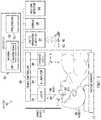
- FIG. 1illustrates an embodiment of a system 10 for controlling a laser device 20 using a haptic sensory pattern.
- System 10allows for control of laser device 20 without requiring the user (e.g., surgeon) to touch laser device 20 , which reduces contamination of laser device 20 .
- system 10comprises laser device 20 , a haptic sensation generator 22 , a display 24 , a gesture detector 26 , a patient support 28 , and a computer 30 coupled as shown.
- Laser device 20generates a laser beam used to perform a medical procedure on a patient 29 , e.g., ophthalmic surgery on an eye.
- Haptic sensation generator 22generates an acoustic field that projects a sensory pattern onto a user that the user can feel.
- the sensory patternmay provide information to the user. For example, to indicate the distance between the focal point of the laser beam and a target, the pattern may feel larger to indicate a longer distance or smaller to indicate a shorter distance.
- the sensory patternmay operate as a user controller that the user can interact with to make an adjustment in system 10 . For example, the pattern may feel like a knob the user can turn.
- display 24displays a graphic element.
- the graphic elementmay provide a visual representation of the information provided to the user. For example, to indicate the distance between the focal point and target, the graphic element may be larger to indicate a longer distance or smaller to indicate a shorter distance.
- the graphic elementmay provide a visual representation of the user controller.
- the graphic elementmay look like a knob.
- Gesture detector 26detects a gesture of the user, such as a gesture of the user interacting with the user controller.
- the gesturemay be the user turning something like a knob.
- Patient support 28e.g., a patient bed or a headrest
- Computer 30sends instructions to laser device 20 , haptic sensation generator 22 , display 24 , gesture detector 26 , and/or patient support 28 to control their operation.
- Laser device 20generates a laser beam 40 .
- laser device 20comprises a laser 32 , an illuminator 34 , a distance meter 36 , and a device controller computer 28 .
- Laser 32generates a laser beam 40 with a focal point F.
- Laser beam 40may define an xyz-coordinate system.
- the axis of laser beam 40defines the z-axis, which is normal to the xy-plane.
- Examples of laser 32include an excimer laser (an ultraviolet laser with a pulse repetition rate of ⁇ 100 Hz to 8 kHz and a pulse duration of ⁇ 10 ns to 30 ns) and a femtosecond laser (an ultrashort pulse laser that can emit light in the infrared or ultraviolet wavelength range).
- An excimer lasergenerates a laser beam that can photoablate tissue in order to, e.g., reshape corneal tissue.
- a femtosecond lasergenerates a laser beam that can create laser-induced optical breakdowns (LIOBs) in tissue in order to, e.g., create an incision in corneal tissue.
- Laser device 20may include other components that control beam 40 , e.g., a scanner, optical elements, and a focusing objective.
- the proceduremay be any suitable medical procedure on patient 29 that cuts or shapes tissue of patient 29 , such as an ophthalmic surgical procedure on an eye 50 of patient 29 .
- focal point Fmay be directed to a target T of eye 50 .
- Target Tmay be a point on the surface of eye 50 or a point within tissue, e.g., corneal, lens, or retinal tissue, of eye 50 .
- target Tmay be a point on the surface of the skin or a point within epidermal tissue.
- Illuminator 34comprises any suitable light source that generates light (e.g., visible or infrared light) that can illuminate the area of the procedure.
- the intensity and/or directionmay be controlled by device controller computer 38 .
- Distance meter 36measures distance, e.g., the distance between focal point F and target T of eye 50 .
- Any suitable distance meter 36may be used.
- distance meter 36may have diodes that direct non-parallel light beams toward eye 50 to form light spots on the surface of eye 50 . As eye 50 is adjusted closer to or farther away from laser 32 , the spots move closer together or farther apart. In some cases, the spots can overlap when eye 50 is at a specific distance from laser 32 .
- Distance meter 36may have a camera that views the spots to determine the distance from laser 32 .
- Device controller computer 88may be a computer that controls the operation of laser device 20 by sending instructions to its components, e.g., laser 32 , illuminator 34 , and distance meter 36 .
- Haptic sensation generator 22generates an acoustic field that projects a sensory pattern 60 onto a user 62 .
- Sensory pattern 60is a tactile sensation that can be felt by user 62 , e.g., a human. In the case of a human, sensory pattern 60 is usually felt by a hand, but can be felt by any part of the human body. In certain cases, sensory pattern 60 operates as a user controller, so user 62 can interact with sensory pattern 60 by making a gesture that sends a command.
- Any suitable haptic sensation generator 22may be used, e.g., an ULTRAHAPTICS TOUCH device. Any suitable sensory pattern 60 may be projected, and examples of patterns 60 are described with reference to FIGS. 2A-3B .
- haptic sensation generator 22includes an array of transducers that projects an acoustic field onto a human. Each transducer outputs an acoustic wave that yields the resulting acoustic field. The frequency of the field is controlled such that the human perceives a haptic sensation.
- the acoustic wavescomprise ultrasound waves that are modulated at a frequency between 0.1 Hz to 500 Hz.
- Display 24displays a graphic element.
- Display 24may be a computer monitor that presents visual information, such as a graphic element.
- a graphic elementis an image, typically with a size, color, and/or shape that has a specific meaning.
- a graphic elementmay represent a user controller, and the element may be displayed when a sensory pattern 60 that operates as the user controller is generated for user 62 .
- user 62can gesture to interact with sensory pattern 60 to send a command to system 10 .
- Another graphic elementmay be a graphic response to the gesture that is detected by gesture detector 26 .
- the graphic elementmay be highlighting to indicate user 62 has gestured to interact with sensory pattern 60 . Examples of graphic elements are described with reference to FIGS. 2A-3B .
- Gesture detector 26detects a gesture of the user.
- a gestureis a movement of the user, e.g., movement of a hand, foot, head, or other part of the user. The movement may be in any suitable direction at any suitable speed. Examples of gestures are described with reference to FIGS. 2A-2E .
- Gesture detector 26may use any suitable detector to detect gestures, such as a depth-aware camera (e.g., structured light or time-of-flight camera), a stereo camera, or a gesture-based controller. After detecting a gesture, gesture detector 26 may provide a description of the gesture to computer 30 .
- a depth-aware camerae.g., structured light or time-of-flight camera
- stereo camerae.g., stereo camera
- gesture detector 26may provide a description of the gesture to computer 30 .
- Computer 30controls the operation of system 10 , and includes processors 51 and a memory 52 .
- Processors 51carry out operations according to instructions 54 , which are stored in memory 52 .
- Computer 30can perform any suitable operations. For example, computer 30 receives a measurement of the distance between focal point F and target T from distance meter 36 ; determines the pattern corresponding to the distance according to a function in which the distance is a variable; and instructs haptic sensation generator 22 to generate an acoustic field that projects the determined pattern. Any suitable function may be used; examples of functions are described with reference to FIGS. 3A-3B .
- computer 30instructs haptic sensation generator 22 to generate an acoustic field that projects a sensory pattern corresponding to a user controller, and instructs display 24 to display a graphic element representing the user controller.
- Computer 30receives a description of a gesture of user 62 interacting with the user controller.
- Computer 30then instructs display 24 to display a graphic response to the gesture. Examples of graphic responses are described with reference to FIGS. 2A-3B .
- Computer 30also determines an operation corresponding to the gesture and provides instructions to perform the operation. The operation may be determined using a table that associates gestures with operations, and may be performed by a component of system 10 .
- Examples of such operationsinclude: instructing laser device 20 to move focal point F or beam 40 closer to or farther away from target T or eye 50 ; instructing illuminator 34 to change illumination, e.g., the brightness or direction of illumination; or instructing patient support 28 to move patient 29 relative to laser device 20 , e.g., farther away from or closer to in the z-direction or along the xy-plane.
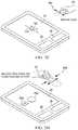
- FIGS. 2A-2Eillustrate examples of sensory pattern 60 operating as a user controller to control components of system 10 .
- haptic sensation generator 22generates a sensory pattern 60 ( 60 a - e ) that operates as a user controller, and display 24 displays a graphic element 70 ( 70 a - e ) representing the user controller.
- User 62gestures to interact with sensory pattern 60 to provide input to system 10 with the user controller.
- Gesture detector 26detects the gesture, and display 24 displays a graphic response 72 ( 72 a - e ) to the gesture.
- Computer 30(shown in FIG. 1 ) sends instructions to the components of system 10 to perform the operation.
- the user controlleris a command button that user 62 can select to trigger an event represented by the button.
- Haptic sensation generator 22generates a sensory pattern 60 a that operates as the button.
- Display 24displays a button element 70 a representing the button.
- User 62gestures to interact with sensory pattern 60 a to select the button, e.g., user 62 moves her hand to press sensory pattern 60 a to select the button.
- Display 24displays a graphic response 72 a representing the pressing, e.g., the button graphic 70 a may be highlighted to show the button has been selected.
- the user controlleris a knob that user 62 can turn to select a value indicated by the knob.
- Haptic sensation generator 22generates a sensory pattern 60 b that operates as the knob.
- Display 24displays a knob element 70 b representing the knob.
- User 62gestures to interact with sensory pattern 60 b to turn the knob, e.g., user 62 moves her hand to turn sensory pattern 60 b to select a value indicated by the knob.
- Display 24displays a graphic response 72 b representing the selection, e.g., the selected value may be highlighted.
- the user controlleris a slider that user 62 can slide to select a value indicated by the slider.
- Haptic sensation generator 22generates a sensory pattern 60 c that operates as the slider.
- Display 24displays a slider element 70 c representing the slider.
- User 62gestures to interact with sensory pattern 60 c to slide the slider, e.g., the user moves her hand to slide sensory pattern 60 c to select a value indicated by the slider.
- Display 24displays a graphic response 72 c representing the selection, e.g., the selected value may be highlighted.
- the user controlleris a shape comprising one or more objects that user 62 can manipulate to select a distance.
- user 62can squeeze sensory pattern 60 operating as the object to select a smaller distance or expand sensory pattern 60 to select a larger distance.
- user 62can move parts of sensory pattern 60 operating as the objects closer together to select a smaller distance or farther apart to select a larger distance.
- haptic sensation generator 22generates a sensory pattern 60 d that represents the shape.
- Display 24displays a shape element 70 d representing the shape.
- User 62gestures to interact with sensory pattern 60 d to manipulate the shape.
- Display 24displays a graphic response 72 d representing the selection, e.g., the selected distance may be displayed.
- the user controlleris a lever that user 62 can raise or lower to select a value indicated by the lever.
- the valuemay be the distance between patient support 28 and laser device 20 , which may be indicated by the height of patient support 28 .
- Haptic sensation generator 22generates a sensory pattern 60 e that operates as the lever.
- Display 24displays a lever element 70 e representing the lever.
- User 62gestures to interact with sensory pattern 60 to slide the slider, e.g., user 62 moves her hand up or down to raise or lower patient support 28 .
- Display 24displays a graphic response 72 e representing the selection, e.g., the selected value may be highlighted.
- FIGS. 3A-3Billustrate examples of a function that computer 30 can apply to determine a sensory pattern 60 .
- a measurementis a variable of the function, so the function can be used to communicate the measurement to user 62 via sensory pattern 60 .
- Any suitable measurementmay be used, e.g., a feature of laser beam 40 such a distance to a target.
- the measurementis the distance d between focal point F and target T.
- the functionmay be stored in any suitable manner, e.g., as a logical or mathematical operation or in a table.
- display 24displays a graphic element 70 with the same shape as sensory pattern 60 .
- Any suitable shapecan be used, e.g., a circle, an oval, a square, a rectangle, or a line.
- Any suitable dimension of the shapecan be used, e.g., the diameter of a circle, the longer or shorter diameter of an oval, the side of a square, the longer or shorter side of a rectangle, or the length of a line.
- a shapemay be two or more spots, and the dimension may be the distance between two spots. In the illustrated embodiment, a longer distance d yields a longer length s.
- the functionyields a first length s i .
- the functionyields a second length s j greater than the first length s i .
- function fyields a different shape for certain values of distance d.
- function fyields a notification alert shape for values of distance d within an alert distance range d*. That is, given a first distance d i outside of an alert distance range d*, the function yields a pattern with a first shape. Given a second distance d k within the alert distance range d*, the function yields a pattern with a second shape.
- the function f of 3 Bmay be used to alert user 62 if focal point F is too close to target T.
- the alert distance range d*may be in the range of 0.05 millimeters (mm) to 0.5 mm, such as 0.05 to 0.1, 0.1 to 0.2, 0.2 to 0.3, 0.3 to 0.4, and/or 0.4 to 0.5 mm.
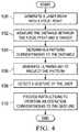
- FIG. 4illustrates an example of a method for providing a measurement and controlling a laser device.
- the methodmay be performed by system 10 of FIG. 1 .
- system 10notifies user 62 of the distance between laser beam focal point F and target T.
- User 62gestures to provide input to system 10 , and system 10 performs an operation in response to the input.
- the methodstarts at step 100 , where laser device 20 generates laser beam 40 with focal point F.
- Distance meter 36measures the distance between focal point F and target T at step 102 .
- Target Tmay be a point on the surface of eye 50 or a point within tissue, e.g., corneal tissue, of eye 50 . In other embodiments, target T may be a point on the surface of the skin or a point within epidermal tissue.
- computer 30determines sensory pattern 60 corresponding to the distance. Pattern 60 may be determined by using a function, as described with reference to FIGS. 3A-3B .
- Haptic sensation generator 22generates ultrasound to project sensory pattern 60 at step 106 .
- Sensory pattern 60is a tactile sensation that can be felt by, e.g., a human hand of user 62 .
- User 62makes a gesture that interacts with pattern 60 .
- the gesturemay interact with pattern 60 as described with reference to FIGS. 2A-2E .
- Gesture detector 26detects the gesture at step 108 .
- computer 30provided instructions to perform an operation corresponding to the gesture.
- Computer 30may determine the operation corresponding to the gesture from, e.g., a table. The operation may be performed by a component of system 10 .
- FIG. 5illustrates an example of a method for controlling a laser device using a haptic sensory pattern.
- the methodmay be performed by system 10 of FIG. 1 .
- system 10projects sensory pattern 60 operating as a user controller.
- User 62gestures to interact to provide input with the user controller, and system 10 performs an operation to respond to the input.
- the methodstarts at step 200 , where laser device 20 generates laser beam 40 to perform a procedure.
- Haptic sensation generator 22generates ultrasound to project sensory pattern 60 operating as a user controller for the procedure at step 202 .
- display 24displays graphic element 70 corresponding to the user controller.
- User 62can interact with a sensory pattern 60 that corresponds to the user controller in order to send a command to system 10 .
- Gesture detector 26detects a gesture of user 62 interacting with the user controller at step 206 .
- computer 20receives a description of the gesture from gesture detector 26 .
- Display 24displays graphic response 72 to the gesture at step 210 .
- computer 30provides instructions to perform an operation corresponding to the gesture for the procedure. Examples of graphic elements 70 , sensory patterns 60 , gestures, and graphic responses 72 are described with reference to FIGS. 2A-2E .
- a componente.g., computer 30 and device controller computer 38 of the systems and apparatuses disclosed herein may include an interface, logic, and/or memory, any of which may include hardware and/or software.
- An interfacecan receive input to the component, provide output from the component, and/or process the input and/or output.
- Logiccan perform the operations of the component, e.g., execute instructions to generate output from input.
- Logicmay be a processor, such as one or more computers or one or more microprocessors.
- Logicmay be computer-executable instructions encoded in memory that can be executed by a computer, such as a computer program or software.
- a memorycan store information and may comprise one or more tangible, non-transitory, computer-readable, computer-executable storage media.
- RAMRandom Access Memory
- ROMRead Only Memory
- mass storage mediae.g., a hard disk
- removable storage mediae.g., a Compact Disk (CD) or a Digital Video Disk (DVD)
- network storagee.g., a server or database.
Landscapes
- Engineering & Computer Science (AREA)
- Health & Medical Sciences (AREA)
- General Engineering & Computer Science (AREA)
- Theoretical Computer Science (AREA)
- Physics & Mathematics (AREA)
- Life Sciences & Earth Sciences (AREA)
- Surgery (AREA)
- General Health & Medical Sciences (AREA)
- Human Computer Interaction (AREA)
- Ophthalmology & Optometry (AREA)
- Animal Behavior & Ethology (AREA)
- Nuclear Medicine, Radiotherapy & Molecular Imaging (AREA)
- Veterinary Medicine (AREA)
- Public Health (AREA)
- Biomedical Technology (AREA)
- Heart & Thoracic Surgery (AREA)
- General Physics & Mathematics (AREA)
- Optics & Photonics (AREA)
- Vascular Medicine (AREA)
- Molecular Biology (AREA)
- Medical Informatics (AREA)
- Robotics (AREA)
- Multimedia (AREA)
- Audiology, Speech & Language Pathology (AREA)
- Electromagnetism (AREA)
- Otolaryngology (AREA)
- User Interface Of Digital Computer (AREA)
Abstract
Description
Claims (16)
Priority Applications (1)
| Application Number | Priority Date | Filing Date | Title |
|---|---|---|---|
| US16/034,202US10918450B2 (en) | 2017-07-27 | 2018-07-12 | Controlling a laser surgical device with a sensation generator and a gesture detector |
Applications Claiming Priority (2)
| Application Number | Priority Date | Filing Date | Title |
|---|---|---|---|
| US201762537837P | 2017-07-27 | 2017-07-27 | |
| US16/034,202US10918450B2 (en) | 2017-07-27 | 2018-07-12 | Controlling a laser surgical device with a sensation generator and a gesture detector |
Publications (2)
| Publication Number | Publication Date |
|---|---|
| US20190029769A1 US20190029769A1 (en) | 2019-01-31 |
| US10918450B2true US10918450B2 (en) | 2021-02-16 |
Family
ID=63244642
Family Applications (1)
| Application Number | Title | Priority Date | Filing Date |
|---|---|---|---|
| US16/034,202Active2038-10-25US10918450B2 (en) | 2017-07-27 | 2018-07-12 | Controlling a laser surgical device with a sensation generator and a gesture detector |
Country Status (5)
| Country | Link |
|---|---|
| US (1) | US10918450B2 (en) |
| EP (1) | EP3659013B1 (en) |
| JP (1) | JP7194124B2 (en) |
| AU (1) | AU2018306524A1 (en) |
| WO (1) | WO2019021097A1 (en) |
Cited By (13)
| Publication number | Priority date | Publication date | Assignee | Title |
|---|---|---|---|---|
| US11399980B2 (en)* | 2017-07-27 | 2022-08-02 | Alcon Inc. | Controlling a laser surgical device with a sensation generator |
| US11504197B1 (en) | 2021-03-31 | 2022-11-22 | Moon Surgical Sas | Co-manipulation surgical system having multiple operational modes for use with surgical instruments for performing laparoscopic surgery |
| US11812938B2 (en) | 2021-03-31 | 2023-11-14 | Moon Surgical Sas | Co-manipulation surgical system having a coupling mechanism removeably attachable to surgical instruments |
| US11819302B2 (en) | 2021-03-31 | 2023-11-21 | Moon Surgical Sas | Co-manipulation surgical system having user guided stage control |
| US11832909B2 (en) | 2021-03-31 | 2023-12-05 | Moon Surgical Sas | Co-manipulation surgical system having actuatable setup joints |
| US11832910B1 (en) | 2023-01-09 | 2023-12-05 | Moon Surgical Sas | Co-manipulation surgical system having adaptive gravity compensation |
| US11844583B2 (en) | 2021-03-31 | 2023-12-19 | Moon Surgical Sas | Co-manipulation surgical system having an instrument centering mode for automatic scope movements |
| US11986165B1 (en) | 2023-01-09 | 2024-05-21 | Moon Surgical Sas | Co-manipulation surgical system for use with surgical instruments for performing laparoscopic surgery while estimating hold force |
| US12042241B2 (en) | 2021-03-31 | 2024-07-23 | Moon Surgical Sas | Co-manipulation surgical system having automated preset robot arm configurations |
| US12070280B2 (en) | 2021-02-05 | 2024-08-27 | Alcon Inc. | Voice-controlled surgical system |
| US12167900B2 (en) | 2021-03-31 | 2024-12-17 | Moon Surgical Sas | Co-manipulation surgical system having automated preset robot arm configurations |
| US12178418B2 (en) | 2021-03-31 | 2024-12-31 | Moon Surgical Sas | Co-manipulation surgical system having a coupling mechanism removeably attachable to surgical instruments |
| US12370001B2 (en) | 2023-01-09 | 2025-07-29 | Moon Surgical Sas | Co-manipulation surgical system having automated user override detection |
Families Citing this family (2)
| Publication number | Priority date | Publication date | Assignee | Title |
|---|---|---|---|---|
| WO2022015923A1 (en)* | 2020-07-17 | 2022-01-20 | Smith & Nephew, Inc. | Touchless control of surgical devices |
| EP4492202A1 (en)* | 2023-07-10 | 2025-01-15 | Leica Instruments (Singapore) Pte Ltd | Devices and methods for contactless haptic control |
Citations (9)
| Publication number | Priority date | Publication date | Assignee | Title |
|---|---|---|---|---|
| US20060207978A1 (en)* | 2004-10-28 | 2006-09-21 | Rizun Peter R | Tactile feedback laser system |
| US20110295243A1 (en) | 2010-06-01 | 2011-12-01 | Peyman Gholam A | Laser-based methods and systems for corneal surgery |
| US20140114296A1 (en) | 2012-10-24 | 2014-04-24 | Optimedica Corporation | Graphical user interface for laser eye surgery system |
| WO2014183792A1 (en) | 2013-05-16 | 2014-11-20 | Wavelight Gmbh | Touchless user interface for ophthalmic devices |
| US20150192995A1 (en)* | 2014-01-07 | 2015-07-09 | University Of Bristol | Method and apparatus for providing tactile sensations |
| US20150277735A1 (en) | 2014-03-31 | 2015-10-01 | Magna Electronics Inc. | Vehicle human machine interface with auto-customization |
| WO2016132144A1 (en) | 2015-02-20 | 2016-08-25 | Ultrahaptics Ip Limited | Perceptions in a haptic system |
| US20170004819A1 (en) | 2015-06-30 | 2017-01-05 | Pixie Dust Technologies, Inc. | System and method for manipulating objects in a computational acoustic-potential field |
| US20170123499A1 (en) | 2014-07-11 | 2017-05-04 | New York University | Three dimensional tactile feedback system |
Family Cites Families (1)
| Publication number | Priority date | Publication date | Assignee | Title |
|---|---|---|---|---|
| WO2010042953A1 (en)* | 2008-10-10 | 2010-04-15 | Gesturetek, Inc. | Single camera tracker |
- 2018
- 2018-07-12EPEP18755898.6Apatent/EP3659013B1/enactiveActive
- 2018-07-12JPJP2019565945Apatent/JP7194124B2/enactiveActive
- 2018-07-12AUAU2018306524Apatent/AU2018306524A1/ennot_activeAbandoned
- 2018-07-12WOPCT/IB2018/055174patent/WO2019021097A1/ennot_activeCeased
- 2018-07-12USUS16/034,202patent/US10918450B2/enactiveActive
Patent Citations (10)
| Publication number | Priority date | Publication date | Assignee | Title |
|---|---|---|---|---|
| US20060207978A1 (en)* | 2004-10-28 | 2006-09-21 | Rizun Peter R | Tactile feedback laser system |
| US20110295243A1 (en) | 2010-06-01 | 2011-12-01 | Peyman Gholam A | Laser-based methods and systems for corneal surgery |
| US20140114296A1 (en) | 2012-10-24 | 2014-04-24 | Optimedica Corporation | Graphical user interface for laser eye surgery system |
| WO2014183792A1 (en) | 2013-05-16 | 2014-11-20 | Wavelight Gmbh | Touchless user interface for ophthalmic devices |
| US20150290031A1 (en)* | 2013-05-16 | 2015-10-15 | Wavelight Gmbh | Touchless user interface for ophthalmic devices |
| US20150192995A1 (en)* | 2014-01-07 | 2015-07-09 | University Of Bristol | Method and apparatus for providing tactile sensations |
| US20150277735A1 (en) | 2014-03-31 | 2015-10-01 | Magna Electronics Inc. | Vehicle human machine interface with auto-customization |
| US20170123499A1 (en) | 2014-07-11 | 2017-05-04 | New York University | Three dimensional tactile feedback system |
| WO2016132144A1 (en) | 2015-02-20 | 2016-08-25 | Ultrahaptics Ip Limited | Perceptions in a haptic system |
| US20170004819A1 (en) | 2015-06-30 | 2017-01-05 | Pixie Dust Technologies, Inc. | System and method for manipulating objects in a computational acoustic-potential field |
Cited By (22)
| Publication number | Priority date | Publication date | Assignee | Title |
|---|---|---|---|---|
| US11399980B2 (en)* | 2017-07-27 | 2022-08-02 | Alcon Inc. | Controlling a laser surgical device with a sensation generator |
| US12070280B2 (en) | 2021-02-05 | 2024-08-27 | Alcon Inc. | Voice-controlled surgical system |
| US11812938B2 (en) | 2021-03-31 | 2023-11-14 | Moon Surgical Sas | Co-manipulation surgical system having a coupling mechanism removeably attachable to surgical instruments |
| US11980431B2 (en) | 2021-03-31 | 2024-05-14 | Moon Surgical Sas | Co-manipulation surgical system for use with surgical instruments having a virtual map display to facilitate setup |
| US11786323B2 (en) | 2021-03-31 | 2023-10-17 | Moon Surgical Sas | Self-calibrating co-manipulation surgical system for use with surgical instrument for performing laparoscopic surgery |
| US11622826B2 (en) | 2021-03-31 | 2023-04-11 | Moon Surgical Sas | Co-manipulation surgical system for use with surgical instruments for performing laparoscopic surgery while compensating for external forces |
| US11819302B2 (en) | 2021-03-31 | 2023-11-21 | Moon Surgical Sas | Co-manipulation surgical system having user guided stage control |
| US11832909B2 (en) | 2021-03-31 | 2023-12-05 | Moon Surgical Sas | Co-manipulation surgical system having actuatable setup joints |
| US12396711B2 (en) | 2021-03-31 | 2025-08-26 | Moon Surgical Sas | Co-manipulation surgical system having multiple operational modes for use with surgical instruments for performing surgery |
| US12349995B2 (en) | 2021-03-31 | 2025-07-08 | Moon Surgical Sas | Co-manipulation surgical systems having optical sensors for generating graphical displays |
| US11844583B2 (en) | 2021-03-31 | 2023-12-19 | Moon Surgical Sas | Co-manipulation surgical system having an instrument centering mode for automatic scope movements |
| US11737840B2 (en) | 2021-03-31 | 2023-08-29 | Moon Surgical Sas | Co-manipulation surgical system having a robot arm removeably attachable to surgical instruments for performing laparoscopic surgery |
| US12178418B2 (en) | 2021-03-31 | 2024-12-31 | Moon Surgical Sas | Co-manipulation surgical system having a coupling mechanism removeably attachable to surgical instruments |
| US12011149B2 (en) | 2021-03-31 | 2024-06-18 | Moon Surgical Sas | Co-manipulation surgical system for bedside robotic laparoscopic surgery using surgical instruments |
| US12042241B2 (en) | 2021-03-31 | 2024-07-23 | Moon Surgical Sas | Co-manipulation surgical system having automated preset robot arm configurations |
| US11504197B1 (en) | 2021-03-31 | 2022-11-22 | Moon Surgical Sas | Co-manipulation surgical system having multiple operational modes for use with surgical instruments for performing laparoscopic surgery |
| US12161432B2 (en) | 2021-03-31 | 2024-12-10 | Moon Surgical Sas | Co-manipulation surgical system having a robot arm removeably attachable to surgical instruments for performing laparoscopic surgery |
| US12167900B2 (en) | 2021-03-31 | 2024-12-17 | Moon Surgical Sas | Co-manipulation surgical system having automated preset robot arm configurations |
| US11986165B1 (en) | 2023-01-09 | 2024-05-21 | Moon Surgical Sas | Co-manipulation surgical system for use with surgical instruments for performing laparoscopic surgery while estimating hold force |
| US11839442B1 (en) | 2023-01-09 | 2023-12-12 | Moon Surgical Sas | Co-manipulation surgical system for use with surgical instruments for performing laparoscopic surgery while estimating hold force |
| US12370001B2 (en) | 2023-01-09 | 2025-07-29 | Moon Surgical Sas | Co-manipulation surgical system having automated user override detection |
| US11832910B1 (en) | 2023-01-09 | 2023-12-05 | Moon Surgical Sas | Co-manipulation surgical system having adaptive gravity compensation |
Also Published As
| Publication number | Publication date |
|---|---|
| US20190029769A1 (en) | 2019-01-31 |
| EP3659013A1 (en) | 2020-06-03 |
| JP7194124B2 (en) | 2022-12-21 |
| WO2019021097A1 (en) | 2019-01-31 |
| AU2018306524A1 (en) | 2019-12-05 |
| EP3659013B1 (en) | 2022-03-09 |
| JP2020528290A (en) | 2020-09-24 |
Similar Documents
| Publication | Publication Date | Title |
|---|---|---|
| US10918450B2 (en) | Controlling a laser surgical device with a sensation generator and a gesture detector | |
| EP3975909B1 (en) | Operating mode control systems and methods for a computer-assisted surgical system | |
| US10426339B2 (en) | Apparatuses and methods for parameter adjustment in surgical procedures | |
| JP6856552B2 (en) | Ophthalmic laser surgical device for transepithelial laser refraction correction corneal resection | |
| CN106456148A (en) | Medical devices, systems, and methods using eye gaze tracking | |
| US20220331038A1 (en) | User interface for controlling a surgical system | |
| US11399980B2 (en) | Controlling a laser surgical device with a sensation generator | |
| US20210349534A1 (en) | Eye-tracking system for entering commands | |
| JP7367041B2 (en) | UI for head-mounted display systems | |
| JP7042029B2 (en) | Ophthalmic observation device and its operation method | |
| JP6895278B2 (en) | Ophthalmic observation device and its operation method | |
| EP4299043A1 (en) | Apparatus for ophthalmic treatment | |
| US12383428B2 (en) | Adjusting laser pulses to compensate for interfering objects |
Legal Events
| Date | Code | Title | Description |
|---|---|---|---|
| FEPP | Fee payment procedure | Free format text:ENTITY STATUS SET TO UNDISCOUNTED (ORIGINAL EVENT CODE: BIG.); ENTITY STATUS OF PATENT OWNER: LARGE ENTITY | |
| AS | Assignment | Owner name:NOVARTIS AG, SWITZERLAND Free format text:ASSIGNMENT OF ASSIGNORS INTEREST;ASSIGNOR:WAVELIGHT GMBH;REEL/FRAME:047096/0647 Effective date:20171127 Owner name:WAVELIGHT GMBH, GERMANY Free format text:ASSIGNMENT OF ASSIGNORS INTEREST;ASSIGNOR:MARTIN, PETER;REEL/FRAME:047096/0602 Effective date:20171102 | |
| STPP | Information on status: patent application and granting procedure in general | Free format text:DOCKETED NEW CASE - READY FOR EXAMINATION | |
| AS | Assignment | Owner name:ALCON INC., SWITZERLAND Free format text:CONFIRMATORY DEED OF ASSIGNMENT EFFECTIVE APRIL 8, 2019;ASSIGNOR:NOVARTIS AG;REEL/FRAME:051454/0788 Effective date:20191111 | |
| STPP | Information on status: patent application and granting procedure in general | Free format text:NON FINAL ACTION MAILED | |
| STPP | Information on status: patent application and granting procedure in general | Free format text:RESPONSE TO NON-FINAL OFFICE ACTION ENTERED AND FORWARDED TO EXAMINER | |
| STPP | Information on status: patent application and granting procedure in general | Free format text:NON FINAL ACTION MAILED | |
| STPP | Information on status: patent application and granting procedure in general | Free format text:FINAL REJECTION MAILED | |
| STPP | Information on status: patent application and granting procedure in general | Free format text:NOTICE OF ALLOWANCE MAILED -- APPLICATION RECEIVED IN OFFICE OF PUBLICATIONS | |
| STCF | Information on status: patent grant | Free format text:PATENTED CASE | |
| MAFP | Maintenance fee payment | Free format text:PAYMENT OF MAINTENANCE FEE, 4TH YEAR, LARGE ENTITY (ORIGINAL EVENT CODE: M1551); ENTITY STATUS OF PATENT OWNER: LARGE ENTITY Year of fee payment:4 |