US10918398B2 - Method and apparatus for treating a joint, including the treatment of cam-type femoroacetabular impingement in a hip joint and pincer-type femoroacetabular impingement in a hip joint - Google Patents
Method and apparatus for treating a joint, including the treatment of cam-type femoroacetabular impingement in a hip joint and pincer-type femoroacetabular impingement in a hip jointDownload PDFInfo
- Publication number
- US10918398B2 US10918398B2US15/818,394US201715818394AUS10918398B2US 10918398 B2US10918398 B2US 10918398B2US 201715818394 AUS201715818394 AUS 201715818394AUS 10918398 B2US10918398 B2US 10918398B2
- Authority
- US
- United States
- Prior art keywords
- image
- guidance system
- visual guidance
- computer visual
- bone
- Prior art date
- Legal status (The legal status is an assumption and is not a legal conclusion. Google has not performed a legal analysis and makes no representation as to the accuracy of the status listed.)
- Active
Links
Images


Classifications
- G—PHYSICS
- G06—COMPUTING OR CALCULATING; COUNTING
- G06T—IMAGE DATA PROCESSING OR GENERATION, IN GENERAL
- G06T11/00—2D [Two Dimensional] image generation
- A—HUMAN NECESSITIES
- A61—MEDICAL OR VETERINARY SCIENCE; HYGIENE
- A61B—DIAGNOSIS; SURGERY; IDENTIFICATION
- A61B17/00—Surgical instruments, devices or methods
- A61B17/16—Instruments for performing osteoclasis; Drills or chisels for bones; Trepans
- A61B17/17—Guides or aligning means for drills, mills, pins or wires
- A61B17/1703—Guides or aligning means for drills, mills, pins or wires using imaging means, e.g. by X-rays
- A—HUMAN NECESSITIES
- A61—MEDICAL OR VETERINARY SCIENCE; HYGIENE
- A61B—DIAGNOSIS; SURGERY; IDENTIFICATION
- A61B17/00—Surgical instruments, devices or methods
- A61B17/16—Instruments for performing osteoclasis; Drills or chisels for bones; Trepans
- A61B17/17—Guides or aligning means for drills, mills, pins or wires
- A61B17/1739—Guides or aligning means for drills, mills, pins or wires specially adapted for particular parts of the body
- A61B17/1742—Guides or aligning means for drills, mills, pins or wires specially adapted for particular parts of the body for the hip
- A61B17/175—Guides or aligning means for drills, mills, pins or wires specially adapted for particular parts of the body for the hip for preparing the femur for hip prosthesis insertion
- A—HUMAN NECESSITIES
- A61—MEDICAL OR VETERINARY SCIENCE; HYGIENE
- A61B—DIAGNOSIS; SURGERY; IDENTIFICATION
- A61B34/00—Computer-aided surgery; Manipulators or robots specially adapted for use in surgery
- A61B34/10—Computer-aided planning, simulation or modelling of surgical operations
- A—HUMAN NECESSITIES
- A61—MEDICAL OR VETERINARY SCIENCE; HYGIENE
- A61B—DIAGNOSIS; SURGERY; IDENTIFICATION
- A61B34/00—Computer-aided surgery; Manipulators or robots specially adapted for use in surgery
- A61B34/20—Surgical navigation systems; Devices for tracking or guiding surgical instruments, e.g. for frameless stereotaxis
- A—HUMAN NECESSITIES
- A61—MEDICAL OR VETERINARY SCIENCE; HYGIENE
- A61B—DIAGNOSIS; SURGERY; IDENTIFICATION
- A61B34/00—Computer-aided surgery; Manipulators or robots specially adapted for use in surgery
- A61B34/25—User interfaces for surgical systems
- G—PHYSICS
- G06—COMPUTING OR CALCULATING; COUNTING
- G06T—IMAGE DATA PROCESSING OR GENERATION, IN GENERAL
- G06T11/00—2D [Two Dimensional] image generation
- G06T11/60—Editing figures and text; Combining figures or text
- G—PHYSICS
- G06—COMPUTING OR CALCULATING; COUNTING
- G06T—IMAGE DATA PROCESSING OR GENERATION, IN GENERAL
- G06T7/00—Image analysis
- G06T7/0002—Inspection of images, e.g. flaw detection
- G06T7/0012—Biomedical image inspection
- A—HUMAN NECESSITIES
- A61—MEDICAL OR VETERINARY SCIENCE; HYGIENE
- A61B—DIAGNOSIS; SURGERY; IDENTIFICATION
- A61B17/00—Surgical instruments, devices or methods
- A61B17/16—Instruments for performing osteoclasis; Drills or chisels for bones; Trepans
- A61B17/1659—Surgical rasps, files, planes, or scrapers
- A—HUMAN NECESSITIES
- A61—MEDICAL OR VETERINARY SCIENCE; HYGIENE
- A61B—DIAGNOSIS; SURGERY; IDENTIFICATION
- A61B17/00—Surgical instruments, devices or methods
- A61B17/16—Instruments for performing osteoclasis; Drills or chisels for bones; Trepans
- A61B2017/1602—Mills
- A—HUMAN NECESSITIES
- A61—MEDICAL OR VETERINARY SCIENCE; HYGIENE
- A61B—DIAGNOSIS; SURGERY; IDENTIFICATION
- A61B34/00—Computer-aided surgery; Manipulators or robots specially adapted for use in surgery
- A61B34/10—Computer-aided planning, simulation or modelling of surgical operations
- A61B2034/107—Visualisation of planned trajectories or target regions
- A—HUMAN NECESSITIES
- A61—MEDICAL OR VETERINARY SCIENCE; HYGIENE
- A61B—DIAGNOSIS; SURGERY; IDENTIFICATION
- A61B34/00—Computer-aided surgery; Manipulators or robots specially adapted for use in surgery
- A61B34/20—Surgical navigation systems; Devices for tracking or guiding surgical instruments, e.g. for frameless stereotaxis
- A61B2034/2046—Tracking techniques
- A61B2034/2051—Electromagnetic tracking systems
- A—HUMAN NECESSITIES
- A61—MEDICAL OR VETERINARY SCIENCE; HYGIENE
- A61B—DIAGNOSIS; SURGERY; IDENTIFICATION
- A61B34/00—Computer-aided surgery; Manipulators or robots specially adapted for use in surgery
- A61B34/20—Surgical navigation systems; Devices for tracking or guiding surgical instruments, e.g. for frameless stereotaxis
- A61B2034/2046—Tracking techniques
- A61B2034/2065—Tracking using image or pattern recognition
- A—HUMAN NECESSITIES
- A61—MEDICAL OR VETERINARY SCIENCE; HYGIENE
- A61B—DIAGNOSIS; SURGERY; IDENTIFICATION
- A61B90/00—Instruments, implements or accessories specially adapted for surgery or diagnosis and not covered by any of the groups A61B1/00 - A61B50/00, e.g. for luxation treatment or for protecting wound edges
- A61B90/06—Measuring instruments not otherwise provided for
- A61B2090/067—Measuring instruments not otherwise provided for for measuring angles
- A—HUMAN NECESSITIES
- A61—MEDICAL OR VETERINARY SCIENCE; HYGIENE
- A61B—DIAGNOSIS; SURGERY; IDENTIFICATION
- A61B90/00—Instruments, implements or accessories specially adapted for surgery or diagnosis and not covered by any of the groups A61B1/00 - A61B50/00, e.g. for luxation treatment or for protecting wound edges
- A61B90/36—Image-producing devices or illumination devices not otherwise provided for
- A61B2090/364—Correlation of different images or relation of image positions in respect to the body
- A61B2090/365—Correlation of different images or relation of image positions in respect to the body augmented reality, i.e. correlating a live optical image with another image
- A—HUMAN NECESSITIES
- A61—MEDICAL OR VETERINARY SCIENCE; HYGIENE
- A61B—DIAGNOSIS; SURGERY; IDENTIFICATION
- A61B90/00—Instruments, implements or accessories specially adapted for surgery or diagnosis and not covered by any of the groups A61B1/00 - A61B50/00, e.g. for luxation treatment or for protecting wound edges
- A61B90/39—Markers, e.g. radio-opaque or breast lesions markers
- A61B2090/3966—Radiopaque markers visible in an X-ray image
- G—PHYSICS
- G06—COMPUTING OR CALCULATING; COUNTING
- G06F—ELECTRIC DIGITAL DATA PROCESSING
- G06F3/00—Input arrangements for transferring data to be processed into a form capable of being handled by the computer; Output arrangements for transferring data from processing unit to output unit, e.g. interface arrangements
- G06F3/01—Input arrangements or combined input and output arrangements for interaction between user and computer
- G06F3/048—Interaction techniques based on graphical user interfaces [GUI]
- G06F3/0484—Interaction techniques based on graphical user interfaces [GUI] for the control of specific functions or operations, e.g. selecting or manipulating an object, an image or a displayed text element, setting a parameter value or selecting a range
- G06F3/04845—Interaction techniques based on graphical user interfaces [GUI] for the control of specific functions or operations, e.g. selecting or manipulating an object, an image or a displayed text element, setting a parameter value or selecting a range for image manipulation, e.g. dragging, rotation, expansion or change of colour
- G—PHYSICS
- G06—COMPUTING OR CALCULATING; COUNTING
- G06F—ELECTRIC DIGITAL DATA PROCESSING
- G06F3/00—Input arrangements for transferring data to be processed into a form capable of being handled by the computer; Output arrangements for transferring data from processing unit to output unit, e.g. interface arrangements
- G06F3/01—Input arrangements or combined input and output arrangements for interaction between user and computer
- G06F3/048—Interaction techniques based on graphical user interfaces [GUI]
- G06F3/0487—Interaction techniques based on graphical user interfaces [GUI] using specific features provided by the input device, e.g. functions controlled by the rotation of a mouse with dual sensing arrangements, or of the nature of the input device, e.g. tap gestures based on pressure sensed by a digitiser
- G06F3/0488—Interaction techniques based on graphical user interfaces [GUI] using specific features provided by the input device, e.g. functions controlled by the rotation of a mouse with dual sensing arrangements, or of the nature of the input device, e.g. tap gestures based on pressure sensed by a digitiser using a touch-screen or digitiser, e.g. input of commands through traced gestures
- G—PHYSICS
- G06—COMPUTING OR CALCULATING; COUNTING
- G06T—IMAGE DATA PROCESSING OR GENERATION, IN GENERAL
- G06T2207/00—Indexing scheme for image analysis or image enhancement
- G06T2207/10—Image acquisition modality
- G06T2207/10116—X-ray image
- G—PHYSICS
- G06—COMPUTING OR CALCULATING; COUNTING
- G06T—IMAGE DATA PROCESSING OR GENERATION, IN GENERAL
- G06T2207/00—Indexing scheme for image analysis or image enhancement
- G06T2207/30—Subject of image; Context of image processing
- G06T2207/30004—Biomedical image processing
- G06T2207/30008—Bone
Definitions
- This inventionrelates to surgical methods and apparatus in general, and more particularly to surgical methods and apparatus for treating a hip joint.
- the hip jointmovably connects the leg to the torso.
- the hip jointis a ball-and-socket joint, and is capable of a wide range of different motions, e.g., flexion and extension, abduction and adduction, internal and external rotation, etc. See FIGS. 1A-1D .
- the hip jointWith the possible exception of the shoulder joint, the hip joint is perhaps the most mobile joint in the body.
- the hip jointcarries substantial weight loads during most of the day, in both static (e.g., standing and sitting) and dynamic (e.g., walking and running) conditions.
- the hip jointis susceptible to a number of different pathologies. These pathologies can have both congenital and injury-related origins. In some cases, the pathology can be substantial at the outset. In other cases, the pathology may be minor at the outset but, if left untreated, may worsen over time. More particularly, in many cases an existing pathology may be exacerbated by the dynamic nature of the hip joint and the substantial weight loads imposed on the hip joint.
- the pathologymay, either initially or thereafter, significantly interfere with patient comfort and lifestyle. In some cases the pathology may be so severe as to require partial or total hip replacement. A number of procedures have been developed for treating hip pathologies short of partial or total hip replacement, but these procedures are generally limited in scope due to the significant difficulties associated with treating the hip joint.
- the hip jointis formed at the junction of the femur and the hip. More particularly, and looking now at FIG. 2 , the ball of the femur is received in the acetabular cup of the hip, with a plurality of ligaments and other soft tissue serving to hold the bones in articulating condition.
- the femuris generally characterized by an elongated body terminating, at its top end, in an angled neck which supports a hemispherical head (also sometimes referred to as the ball).
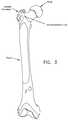
- a large projection known as the greater trochanterprotrudes laterally and posteriorly from the elongated body adjacent to the neck.
- a second, somewhat smaller projection known as the lesser trochanterprotrudes medially and posteriorly from the elongated body adjacent to the neck.
- An intertrochanteric crestextends along the periphery of the femur, between the greater trochanter and the lesser trochanter.
- the hipis made up of three constituent bones: the ilium, the ischium and the pubis. These three bones cooperate with one another (they typically ossify into a single “hip bone” structure by the age of 25) so as to form the acetabular cup.
- the acetabular cupreceives the head of the femur.
- Both the head of the femur and the acetabular cupare covered with a layer of articular cartilage which protects the underlying bone and facilitates motion. See FIG. 6 .
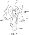
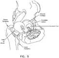
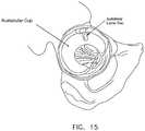
- ligaments and soft tissueserve to hold the ball of the femur in place within the acetabular cup. More particularly, and looking now at FIGS. 7 and 8 , the ligamentum teres extends between the ball of the femur and the base of the acetabular cup. As seen in FIG. 9 , a labrum is disposed about the perimeter of the acetabular cup. The labrum serves to increase the depth of the acetabular cup and effectively establishes a suction seal between the ball of the femur and the rim of the acetabular cup, thereby helping to hold the head of the femur in the acetabular cup. In addition, and looking now at FIG.
- a fibrous capsuleextends between the neck of the femur and the rim of the acetabular cup, effectively sealing off the ball-and-socket members of the hip joint from the remainder of the body.
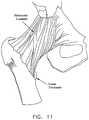
- the foregoing structuresare encompassed and reinforced by a set of three main ligaments (i.e., the iliofemoral ligament, the ischiofemoral ligament and the pubofemoral ligament) which extend between the femur and the hip. See FIGS. 11 and 12 .
- the hip jointis susceptible to a number of different pathologies. These pathologies can have both congenital and injury-related origins.
- one important type of congenital pathology of the hip jointinvolves impingement between the neck of the femur and the rim of the acetabular cup.
- this impingementcan occur due to irregularities in the geometry of the femur.
- This type of impingementis sometimes referred to as a cam-type femoroacetabular impingement (i.e., a cam-type FAI).
- the impingementcan occur due to irregularities in the geometry of the acetabular cup.
- Impingementcan result in a reduced range of motion, substantial pain and, in some cases, significant deterioration of the hip joint.
- another important type of congenital pathology of the hip jointinvolves defects in the articular surface of the ball and/or the articular surface of the acetabular cup. Defects of this type sometimes start out fairly small but often increase in size over time, generally due to the dynamic nature of the hip joint and also due to the weight-bearing nature of the hip joint. Articular defects can result in substantial pain, induce or exacerbate arthritic conditions and, in some cases, cause significant deterioration of the hip joint.
- one important type of injury-related pathology of the hip jointinvolves trauma to the labrum. More particularly, in many cases, an accident or a sports-related injury can result in the labrum being torn, typically with a tear running through the body of the labrum. See FIG. 15 . These types of injuries can be painful for the patient and, if left untreated, can lead to substantial deterioration of the hip joint.
- minimally-invasive techniquesBy way of example but not limitation, it is common to re-attach ligaments in the shoulder joint using minimally-invasive, “keyhole” techniques which do not require “laying open” the capsule of the shoulder joint. By way of further example but not limitation, it is common to repair torn meniscal cartilage in the knee joint, and/or to replace ruptured ACL ligaments in the knee joint, using minimally-invasive techniques. While such minimally-invasive approaches can require additional training on the part of the surgeon, such procedures generally offer substantial advantages for the patient and have now become the standard of care for many shoulder joint and knee joint pathologies.
- minimally-invasive treatments for pathologies of the hip jointhave lagged behind minimally-invasive treatments for pathologies of the shoulder joint and knee joint. This is generally due to (i) the geometry of the hip joint itself, and (ii) the nature of the pathologies which must typically be addressed in the hip joint.
- the hip jointis generally considered to be a “tight” joint, in the sense that there is relatively little room to maneuver within the confines of the joint itself. This is in marked contrast to the knee joint, which is generally considered to be relatively spacious when compared to the hip joint. As a result, it is relatively difficult for surgeons to perform minimally-invasive procedures on the hip joint.
- the natural pathways for entering the interior of the hip jointi.e., the pathways which naturally exist between adjacent bones
- the pathways which naturally exist between adjacent bonesare generally much more constraining for the hip joint than for the shoulder joint or the knee joint. This limited access further complicates effectively performing minimally-invasive procedures on the hip joint.
- the nature and location of the pathologies of the hip jointalso complicate performing minimally-invasive procedures.
- a typical tear of the labrum in the hip jointIn this situation, instruments must generally be introduced into the joint space using a line of approach which is set, in some locations, at an angle of 25 degrees or more to the line of repair. This makes drilling into bone, for example, much more complex than where the line of approach is effectively aligned with the line of repair, such as is frequently the case in the shoulder joint.
- the working space within the hip jointis typically extremely limited, further complicating repairs where the line of approach is not aligned with the line of repair.
- hip arthroscopyis becoming increasingly more common in the diagnosis and treatment of various hip pathologies.
- hip arthroscopyis currently practical for only selected pathologies and, even then, hip arthroscopy has generally met with limited success.
- cam-type femoroacetabular impingementi.e., cam-type FAI
- cam-type femoroacetabular impingementirregularities in the geometry of the femur can lead to impingement between the femur and the rim of the acetabular cup.
- Treatment for cam-type femoroacetabular impingementtypically involves debriding the femoral neck and/or head, using instruments such as burrs and osteotomes, to remove the bony deformities causing the impingement.
- debridement templateshaving a pre-shaped curvature to guide them in removing the appropriate amount of bone from the femur.
- the surgeoncannot view the entire pathology “all at once.”
- the surgeonalso utilizes a fluoroscope to take X-ray images of the anatomy. These X-ray images supplement the arthroscopic view from the scope, but it is still limited to a 2D representation of the 3D cam pathology.
- a primary object of the present inventionis to provide the surgeon with a novel method and apparatus for guiding the surgeon during an arthroscopic debridement procedure to treat cam-type femoroacetabular impingement.
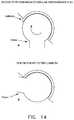
- pincer-type femoroacetabular impingementi.e., pincer-type FAI
- pincer-type femoroacetabular impingementi.e., pincer-type FAI
- pincer-type femoroacetabular impingementirregularities in the geometry of the acetabulum can lead to impingement between the femur and the rim of the acetabular cup.
- Treatment for pincer-type femoroacetabular impingementtypically involves debriding the rim of the acetabular cup using instruments such as burrs and osteotomes to remove the bony deformities causing the impingement.
- the labrumis released from the acetabular bone so as to expose the underlying rim of the acetabular cup prior to debriding the rim of the acetabular cup, and then the labrum is reattached to the debrided rim of the acetabular cup.
- another object of the present inventionis to provide the surgeon with a novel method and apparatus for guiding the surgeon during an arthroscopic debridement procedure to treat pincer-type femoroacetabular impingement.
- Two common anatomical measurements used in diagnosing femoroacetabular impingementare the Alpha Angle ( FIG. 16 ) for cam-type impingement and the Center Edge Angle ( FIG. 17 ) for pincer-type impingement. These measurements are typically measured from pre-operative images (e.g., pre-operative X-ray images). These measurements are used to determine the degree to which the patient's hip anatomy deviates from normal, healthy hip anatomy.
- a healthy hiptypically has an Alpha Angle of anywhere from less than approximately 42 degrees to approximately 50 degrees; thus, a patient with an Alpha Angle of greater than approximately 42 degrees to approximately 50 degrees may be a candidate for FAI surgery.
- the surgeonwill typically take an X-ray of the patient's hip. If the patient has an initial diagnosis of FAI, the patient may also obtain an MRI or CT scan of their hip for further evaluation of the bony pathology causing the FAI.
- Most of today's imaging techniquesare digital, and hence the images can be imported into, and manipulated by, computer software.
- the surgeonis able to measure the Alpha Angle (and/or the Center Edge Angle).
- the surgeonimports the digital image into one of the many available software programs that use the DICOM (Digital Imaging and Communications in Medicine) standard for medical imaging.
- DICOMDigital Imaging and Communications in Medicine
- the surgeonmust first manually create and overlay geometric shapes onto the digital medical image.
- the surgeonmanually creates a circle 5 and places it over the femoral head 10 , and then manually sizes the circle such that the edge of the circle matches the edge of the femoral head.
- the surgeonthen manually creates a line 15 and places it along the mid-line of the femoral neck 20 .
- the surgeonthen manually draws a second line 25 which originates at the center of the femoral head and passes through the location which signifies the start of the cam pathology 30 (i.e., the location where the bone first extends outside the circle set around the femoral head).
- the surgeonthen manually selects the two lines and instructs the software to calculate the angle between the two lines; the result is the Alpha Angle 35 .
- the surgeonmanually creates a vertical line 40 which originates at the center of the femoral head, and then manually draws a second line 45 which originates at the center of the femoral head and passes through the location which signifies the start of the pincer pathology 50 (i.e., the rim of the acetabular cup).
- the surgeonthen manually selects the two lines and instructs the software to calculate the angle between the two lines; the result is the Center Edge Angle 55 .
- the surgeoncan position one or more planes through the femoral head, and then performs the same operations within the one or more planes to measure the Alpha Angle for a given plane.
- 3D medical imagese.g., CT, MRI, etc.
- Alpha Angle measurementsare typically performed around the time that the patient is initially examined, which typically occurs weeks or months prior to surgery.
- the surgeonmay bring a copy (e.g., a printout) of the Alpha Angle measurements (or the Center Edge Angle measurements) to the operating room so that the printout is available as a reference during surgery.
- the surgeonmay also have access to these measurements with a computer located in or near the operating room, which is connected to the hospital's PACS system (Picture Archiving and Communication System). Either way, the surgeon can have the pre-operative measurements available as a reference during surgery.
- PACS systemPicture Archiving and Communication System
- the surgeoncannot get an updated measurement of the Alpha Angle (or the Center Edge Angle) to determine if more bone needs to be removed.
- the patientwould have to be moved out of the operating room to the imaging room, the necessary image(s) obtained, the measurements (Alpha Angle or Center Edge Angle) calculated, and then the patient moved back to the operating room.
- the time necessary to do thiswhile requiring the operating room staff to wait, in addition to the inability to maintain sterility of the patient's surgical site, make this an impractical solution.
- the surgeonlacks the ability to measure the Alpha Angle (and/or the Center Edge Angle) during surgery.
- another object of the present inventionis to provide the surgeon with a novel method and apparatus to take images at multiple time points during a surgery, measure the anatomy using the images, and then continue the surgery, all without disrupting the surgical procedure.
- the present inventioncomprises a novel method and apparatus for treating a joint.
- a novel method and apparatus for guiding the surgeon during an arthroscopic debridement procedure to treat cam-type femoroacetabular impingementIn one preferred form of the invention, there is provided a novel computer visual guidance system wherein a 2D image obtained from an ordinary C-arm X-ray device is automatically analyzed and annotated so as to provide the surgeon with additional information for guiding the surgeon through an arthroscopic debridement procedure to treat cam-type femoroacetabular impingement.
- the surgeonlines up the C-arm X-ray device with the patient's hip, captures an X-ray image of the hip (femur and acetabulum), and the computer visual guidance system then automatically detects the edges of the femur and acetabulum, and computes and displays measurements of the cam pathology.
- the computer visual guidance systemmay additionally identify the cam pathology which is to be removed, and then annotate the C-arm image so as to show the surgeon the bone which is to be removed.
- the surgeonpreferably utilizes this tool iteratively during the resection until the cam pathology is completely removed, thereby ensuring that the appropriate bone is resected.
- This iterative approachcan be repeated with the patient's leg in multiple positions so that the 2D projection of the cam pathology is visible under a variety of fluoroscopic visualizations.
- an Alpha Angle diagramis displayed.
- the advantage of utilizing the Alpha Angle measurementis that it is already commonly used to diagnose patients with cam-type impingement.
- Alpha Angle measurementshave practical limitations.
- the Alpha Angledescribes where the femoral head stops being round, but it does not define how far a resection should go around the head (e.g., further medial or lateral or posterior), nor does it define how far distally down the neck that resection should be smoothed and extended.
- a second lineis drawn for the Alpha Angle, with the second line designating the target Alpha Angle (in addition to the currently-measured Alpha Angle).
- the area outside the femoral head circle and between the currently-measured Alpha Angle line and the target Alpha Angle linedescribes the initial cam pathology which is to be removed, which is roughly triangular.
- a smooth transitionis preferably provided between the bone resection and the remaining bone. This process is then preferably repeated by either re-positioning the patient's leg or moving the C-arm so as to obtain additional projections. It will be appreciated that obtaining a plurality of projections allows the surgeon to approximate the total 3D resection.
- a novel method and apparatus for guiding the surgeon during an arthroscopic debridement procedure to treat pincer-type femoroacetabular impingementIn another preferred form of the present invention, there is provided a novel method and apparatus for guiding the surgeon during an arthroscopic debridement procedure to treat pincer-type femoroacetabular impingement.
- a novel computer visual guidance systemwherein a 2D image obtained from an ordinary C-arm X-ray device is analyzed and annotated so as to provide the surgeon with additional information for guiding the surgeon through an arthroscopic debridement procedure to treat pincer-type femoroacetabular impingement.
- the surgeonlines up the C-arm X-ray device with the patient's hip, captures an X-ray image of the hip (femur and acetabulum), and then the computer visual guidance system automatically detects the edges of the femur and acetabulum, and then computes and displays measurements of the pincer pathology.
- the computer visual guidance systemmay additionally identify the pincer pathology which is to be removed, and then annotate the C-arm image so as to show the surgeon the bone which is to be removed.
- an automatic Center Edge Angle measurementis performed and a Center Edge Angle diagram is displayed. Due to the fact that the Center Edge Angle requires proper vertical orientation of the pelvis, additional anatomy must be present in the X-ray image.
- the systemcan either utilize the contralateral femoral head to establish the horizontal plane for the Center Edge Angle measurement, or the system can use the pubic synthesis to establish the vertical plane for the Center Edge Angle measurement (however, this latter approach is typically less preferred since it is generally less accurate).
- a simple measurement of the Center Edge Anglehas its limitations. More particularly, a simple measurement of the Center Edge Angle does not define how far a resection should go, nor does it describe how the resection should be smoothed and extended. Therefore, in further embodiments of the invention, a target line and resection smoothing may be provided. Furthermore, an iterative approach to both resection and orientation are desirable to ensure a precise resection.
- annotating X-ray imagesis not, in itself, novel.
- Alpha Angle, Center Edge Angle and other resection measurements and annotationsare routinely conducted pre-operatively. However, these measurements and annotations are done manually by the surgeon or by the radiologist. And, significantly, these resection measurements and annotations are done pre-operatively—once a surgeon has scrubbed into surgery and the patient is under anesthesia, time is limited and the surgeon is busy manipulating the arthroscope and the resection instruments. Prior to the present invention, surgeons were not able to take resection measurements and have annotations on the X-ray images in real time during surgery.
- the computer visual guidance system of the present inventionmakes assisted surgery quick, accurate and hands-free.
- a computer visual guidance systemfor guiding a surgeon through an arthroscopic debridement of a bony pathology, wherein the computer visual guidance system is configured to:
- a method for guiding a surgeon through an arthroscopic debridement of a bony pathologycomprising:
- FIGS. 1A-1Dare schematic views showing various aspects of hip motion
- FIG. 2is a schematic view showing bone structures in the region of the hip joint
- FIG. 3is a schematic anterior view of the femur
- FIG. 4is a schematic posterior view of the top end of the femur
- FIG. 5is a schematic view of the pelvis
- FIGS. 6-12are schematic views showing bone and soft tissue structures in the region of the hip joint
- FIG. 13is a schematic view showing cam-type femoroacetabular impingement (i.e., cam-type FAI);
- FIG. 14is a schematic view showing pincer-type femoroacetabular impingement (i.e., pincer-type FAI);
- FIG. 15is a schematic view showing a labral tear
- FIG. 16is a schematic view showing an Alpha Angle determination on the hip of a patient
- FIG. 17is a schematic view showing a Center Edge Angle determination on the hip of a patient
- FIG. 18is a schematic view showing the head and neck of a femur and a cam-type femoroacetabular impingement site;
- FIG. 19is a schematic view showing a surgical suite incorporating the present invention.
- FIG. 20is a flowchart which shows one preferred implementation of the present invention.
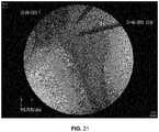
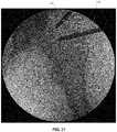
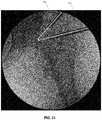
- FIG. 21is a schematic view showing a typical image acquired by a C-arm X-ray device
- FIG. 22is a schematic view showing a typical image acquired from a medical center's PACS servers
- FIG. 23is a schematic view showing how an X-ray image can be de-warped
- FIG. 24is a schematic view showing one way for calibrating pixel size
- FIGS. 25 and 26are schematic views showing another way for calibrating pixel size
- FIG. 27is a schematic view showing still another way for calibrating pixel size
- FIG. 28is a schematic view showing how a surgeon can provide “hints” to the system using touchscreen tablet 130 ;
- FIG. 29is a schematic view showing one way of determining whether the X-ray image is of the left hip or the right hip;
- FIG. 30is a schematic view showing how the surgeon-supplied “hints” may be used to determine whether the X-ray image is of the left hip or the right hip;
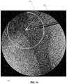
- FIG. 31is a schematic view showing one way for providing a clue of where to start the analysis of the anatomy
- FIG. 32is a schematic view showing one way for determining the search area
- FIG. 33is a schematic view showing edge detection
- FIG. 33Ais a schematic view showing estimation of the femoral head
- FIG. 34is a schematic view showing another way for finding the femoral head
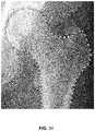
- FIG. 35is a schematic view showing one way for finding where the femoral neck stops being round and the cam legion starts;
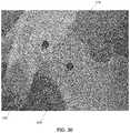
- FIG. 36is a schematic view showing one way of measuring the Alpha Angle and for drawing extra features on the X-ray image
- FIG. 37is a schematic view showing the resection curve for treating cam-type femoroacetabular impingement
- FIG. 38is a schematic view showing another way of drawing extra features on the X-ray image.
- FIG. 39is a schematic view showing one way of drawing extra features on the X-ray image.
- FIG. 40is a schematic view showing another way of drawing extra features on the X-ray image
- FIG. 41is a schematic view showing another way of drawing extra features on the X-ray image
- FIGS. 42-44is a series of schematic views showing Alpha Angle recalculations to track progress during the resecting of a cam pathology
- FIGS. 45-47is a series of schematic views showing Alpha Angle recalculations to track progress during the resecting of a cam pathology
- FIG. 48is a schematic view showing pincer-type femoroacetabular impingement.
- FIG. 49is a schematic view showing a Center Edge Angle calculation.
- the present inventioncomprises a novel method and apparatus for treating a joint.
- FIG. 18is a schematic view of a femur 60 comprising the femoral head 10 and the femoral neck 20 , and illustrates the cam-type femoroacetabular impingement site 30 which needs to be debrided in order to treat the cam-type femoroacetabular impingement.
- the present inventioncomprises the provision and use of a novel computer visual guidance system which analyzes an X-ray image (e.g., an intra-operative C-arm X-ray image) to automatically measure features of the hip, such as the cam pathology (e.g., by using an “Alpha Angle” calculation, see below), and then annotates the X-ray image for use by the surgeon in treating the cam pathology.
- the purpose of this inventionis to guide the surgeon to an optimal resection of the pathology which is causing the impingement.
- arthroscopic resectionsare currently “eye-balled” and the surgeon has no objective way to define completion of the boney resection.
- the present inventionaddresses this problem by providing means which automatically analyze an X-ray image with respect to a cam pathology and then automatically annotate the X-ray image with guidance features which can be used by the surgeon in treating the cam pathology.
- the present inventioncomprises a series of steps which start with an X-ray image and yields a measurement of a feature of the hip (e.g., the Alpha Angle) and an annotation which is correctly displayed on that X-ray image for the surgeon to be able to assess the pathology and progress towards proper resection.
- a feature of the hipe.g., the Alpha Angle
- FIG. 19shows a surgical suite incorporating the present invention. More particularly, in a typical arthroscopic surgical suite, the surgeon uses an arthroscope 105 and a monitor 110 to directly view an internal surgical site. In addition, the surgeon also uses a C-arm X-ray machine 115 and a fluoroscopic monitor 120 to image the internal surgical site. In accordance with the present invention, there is also provided a novel computer visual guidance system 125 which automatically analyzes an X-ray image obtained from C-arm X-ray machine 115 with respect to selected features of the hip associated with a cam pathology and then automatically annotates the X-ray image displayed on computer visual guidance system 125 with guidance features for use by the surgeon in treating the cam pathology.
- a novel computer visual guidance system 125which automatically analyzes an X-ray image obtained from C-arm X-ray machine 115 with respect to selected features of the hip associated with a cam pathology and then automatically annotates the X-ray image displayed on computer visual guidance system 125 with guidance features for use by the surgeon in
- computer visual guidance system 125comprises a general purpose computer having input and output means and which is appropriately programmed so as to provide the functionality disclosed herein.
- computer visual guidance system 125comprises a tablet device with an integrated computer processor and user input/output functionality, e.g., a touchscreen.
- the computer visual guidance system 125may be located in the sterile field, for example, the computer visual guidance system 125 may comprise a touchscreen tablet mounted to the surgical table or to a boom-type tablet support.
- the computer visual guidance system 125may be covered by a sterile drape to maintain the surgeon's sterility as he or she operates the touchscreen tablet.
- computer visual guidance system 125may comprise other general purpose computers with appropriate programming and input/output functionality, e.g., a desktop or laptop computer with a keyboard, mouse, touchscreen display, heads-up display, voice activation feature, pupil reading device, etc.
- the inventioncomprises the steps discussed below and shown in flowchart form in FIG. 20 .
- Step 1Obtain the X-ray Image
- the first stepis to obtain the X-ray image. There are multiple ways to effect this.
- the X-ray imageis obtained directly from a C-arm X-ray device, e.g., C-arm X-ray machine 115 ( FIG. 19 ). This may be done by wire or wireless connection between C-arm X-ray machine 115 and computer visual guidance system 125 .
- the computer visual guidance system 125( FIG. 19 ) is separate from the C-arm X-ray device, it is necessary to detect when a new image has been taken by the C-arm X-ray device. This may be done by connecting the computer visual guidance system 125 directly to the video output of the C-arm X-ray device, and using the method described in International (PCT) Patent Application Publication No. WO 2012/149664A1 (which corresponds to International (PCT) Patent Application No. PCT/EP2011/057105) to detect when a new image is taken. In essence, this method looks at image blocks to see if there is a significant change between one image block and the previous image block. If there is a large change between image blocks, then an image is captured and this captured image is the image used in the method of the present invention.
- the X-ray imagemay also be transmitted from C-arm X-ray machine 115 to computer visual guidance system 125 over a local area network.
- C-arm X-ray machine 115communicates with the local area network with, for example, a wireless or wired connection.
- computer visual guidance system 125receives the X-ray image from the local area network. Depending on the network speed, this can occur substantially instantaneously.
- a surgeonmay also want to use an image taken earlier in the surgical procedure.
- a previous imagecan be retrieved from, for example, the C-arm X-ray machine 115 and imported into computer visual guidance system 125 .
- a previous imagemay, alternatively, be retrieved from the computer visual guidance system 125 and used for further analysis.
- a surgeonmay also want to use an image taken during pre-operative diagnostic X-rays, etc.
- computer visual guidance system 125communicates with the hospital's PACS servers, and an image taken previously is downloaded and the image used in the method of the present invention.
- the pre-operative imageis typically rectangular with no black background.
- the pre-op imagesare inverted relative to the C-arm images. Bones are light, soft tissue is darker, no X-ray absorption is black.
- a pre-op imageneeds to be inverted for analysis (i.e., so as to be similar to a C-arm image) and then inverted back after analysis for viewing. See FIG. 22 .
- pre-operative image configurationsmay also be used—what is important is that both pre-operative and intra-operative images can be utilized with computer visual guidance system 125 . It should also be appreciated that a pre-operative image may be provided to computer visual guidance system 125 by other means, e.g., a USB drive or other static drive or portable storage device, etc.
- the X-ray imageAfter the X-ray image is acquired, it is displayed to the surgeon on computer visual guidance system 125 and/or monitor 110 . See FIGS. 21 and 22 .
- the advantage of displaying the X-ray image to the surgeon prior to making measurements from that X-ray imageis that the surgeon can view the acquired image and determine if it is an appropriate image to analyze and, if not, take another X-ray image without losing valuable operating room (OR) time while waiting for computer visual guidance system 125 to process the image.
- Step 3De-warp the Image
- the next stepis to de-warp the intra-operative X-ray image.
- images from some C-arm X-ray machines 115are often distorted (“warped”) such that every object in the image may not be scaled identically. This is due to the fact that the X-ray beam is not perfectly linear. Typically, objects closer to the X-ray source of the C-arm X-ray device appear larger (and comprise more pixels). Correspondingly, other objects of the same size located further away from the X-ray source of the C-arm X-ray device will appear smaller (and comprise less pixels). To make precise measurements, this warping needs to be removed. For example, the Stryker “Fluoro Disc” product provides this de-warping function by projecting a predetermined pattern onto the intra-operative X-ray image. See FIG. 23 .
- this de-warping stepis optional, however, it makes calibration and any subsequent measurements more accurate (e.g., see Step 16 below), and is generally desirable since it makes the Alpha Angle measurement more accurate by correcting for image distortion via the de-warping process.
- Some newer C-arm X-ray devicese.g., those with a flat panel detector) may automatically provide de-warped images and therefore may not require this de-warping step.
- Step 4Calibrate the Pixel Size
- the next stepis to calibrate the pixel size.
- this pixel calibration stepis optional, however, it is required for the measurement function in Step 16, and is generally desirable since it makes measurements of features shown on an X-ray image more accurate.
- Some newer C-arm X-ray devicese.g., those with a flat panel detector with integrated DICOM may provide calibrated pixel sizes and therefore may not require this pixel calibration step.
- pixelsmust first be calibrated (i.e., so that a pixel in a given image is correlated to a real-world dimension). It is also helpful to know the pixel size when trying to limit the diameters of the femoral head that are being analyzed (see Step 11A below).
- a first way to calibrate pixel sizeis to put a radio-opaque marker on the skin of the patient that is visible in the X-ray image.
- This radio-opaque markercan be large and placed a few centimeters distal from the greater trochanter.
- the radio-opaque markerhas an adhesive on its rear side to stick to the patient's skin.
- the radio-opaque markeris preferably disposable.
- the markeris flat, circular and simple to identify with computer vision. Since the marker is of known size (mm), and the number of pixels can be counted on the X-ray (px), it is a simple matter to calculate mm/px (i.e., to calculate the pixel size).
- pixel calibrationcan be effected by placing a calibration marker of known size into the joint space and, more preferably, directly on the bone.
- the calibration markeris radio-opaque and thus will be visible on X-ray. It is preferably highly radio-opaque, for example constructed of solid metal, and thus will have high contrast with the anatomy. This would make the “plane” of the pixel calibration more accurate, i.e., the calibration marker will lie closer to the plane of the object of interest.
- This calibration markercan be re-usable and sterilized by almost any method due to its simplicity. See FIGS. 25 and 26 , which show a radio-opaque calibration marker 135 at the distal end of an instrument 140 .
- a dedicated calibration markeradds an additional instrument to the procedure, and can disrupt the natural workflow of the medical procedure. If, instead, surgical instruments of known size that are already present in the image (e.g., the burr and scope) can be used, this disruption can be avoided. These surgical instruments (e.g., burr and scope) are much more complex shapes, however, and tend to be more difficult to identify with computer vision. Fortunately, 3D computer models of these surgical instruments are generally available, so these 3D models can be matched up to the 2D X-ray images from the C-arm X-ray machine 115 to first identify the surgical instruments, and then their known dimensions can be used for pixel calibration.
- some surgical instrumentsinclude encoded information that identifies the surgical instrument; by way of example but not limitation, this information can be encoded into the surgical instrument by way of an EPROM carried by the surgical instrument.
- This identifying informationcan include the make and model number of the surgical instrument, or may include physical dimensions.
- This informationcan be passed to computer visual guidance system 125 so that a known dimension of the surgical instrument can be used for pixel calibration. If the information is in the form of a make and model number, then computer visual guidance system 125 may comprise a table of dimensions associated with that particular surgical instrument. See FIG. 27 , which shows a burr 145 and a scope 150 .
- the pixel size in the imagemay also be calibrated based on pre-operative images that have a known scale, such as MRI or CT images. More particularly, if the pre-operative image has a known scale, then an object appearing in both the pre-operative image and intra-operative image can be compared to determine pixel calibration. For example, the radius of the femoral head can be measured. The femoral head radius can be determined from the X-ray image in number of pixels and, using the known femoral head radius measured pre-operatively, the pixel size relative to real-world distance can be computed. However, if the pre-operative and intra-operative images are not taken in the same plane, a small error may be present due to imperfect femoral head symmetry. Creating 2D images from a 3D computer model increases the ability to match the images well and minimize error.
- the pixel size in the X-ray image obtained from C-arm X-ray machine 115is calibrated by (i) first obtaining a measurement of the radius of the femoral head from a pre-operative image, and then (ii) correlating the pixel count of the radius of the femoral head with the previously-obtained measurement of the radius of the femoral head in order to calibrate the pixel size in the X-ray image obtained from C-arm X-ray machine 115 .
- the measurement from the pre-operative imagecan be manually input into computer visual guidance system 125 by the operator (for example, the surgeon).
- computer visual guidance system 125can read the measurement from a file that it accesses.
- the femoral head sizecould be meta data associated with a pdf file that computer visual guidance system 125 accesses.
- the pdf filecan be a pre-operative plan generated from a pre-operative 3D image (e.g., a CT scan).
- Step 4Dwould come after the femoral head has been found using computer vision, e.g., after Step 11 below.
- the next stepis to provide “hints” to the system.
- hintsgenerally serve to speed up the analysis, however, they can also be used for other purposes, e.g., to help identify whether the X-ray image is of the left hip or the right hip, or to help in computing the resection curve (see below), etc.
- the surgeonpreferably provides two hints to the system: a femoral head hint 155 and a femoral neck hint 160 .
- Thisis preferably done by displaying the X-ray image obtained by C-arm X-ray machine 115 onto an output screen of computer visual guidance system 125 (e.g., the touchscreen of a tablet comprising computer visual guidance system 125 ), and then prompting the surgeon to (i) touch the center of the femoral head so as to provide a femoral head hint 155 , and (ii) prompting the surgeon to touch the mid-line of the femoral neck so as to provide a femoral neck hint 160 .
- computer visual guidance system 125e.g., the touchscreen of a tablet comprising computer visual guidance system 125
- femoral head hint 155 and the femoral neck hint 160may be automatically incorporated into subsequent images obtained by C-arm X-ray machine 115 . More particularly, in this form of the invention, a new X-ray image is compared to a previous image containing the femoral head hint 155 and the femoral neck hint 160 . If the new image is sufficiently similar to the previous image, then the femoral head hint 155 and the femoral neck hint 160 from the previous image are used for the new image. This will save valuable OR time and be convenient for the surgeon in that the surgeon will not have to provide new hints to computer visual guidance system 125 for each new image acquired.
- Step 6Determine Whether the X-ray Image is of the Left Hip or the Right Hip
- the next stepis to determine whether the X-ray image is of the left or the right hip.
- knowing whether a left hip or right hip is being imagedenables computer visual guidance system 125 to more efficiently analyze the X-ray image; for example, to search for the femoral neck, computer visual guidance system 125 only need look on the right side of the femoral head for a left hip or on the left side of the femoral head for a right hip.
- the X-ray imageis of the left or the right hip.
- the X-ray imageis provided to the visual guidance system in the correct manner, and has not been flipped (e.g., reversed), and is generally oriented with the top of the image being in the superior (i.e., cephalad) direction of the patient.
- patient data entrymay include identification of the left hip or the right hip.
- Computer visual guidance system 125can subsequently read this data.
- a patient data filemay include the hip type, and computer visual guidance system 125 obtains this information by accessing the patient data file.
- the left or the right hipcan be ascertained by pre-operative software from a 3D image (e.g., CT, MRI) or 2D image (e.g., X-ray) and subsequently read by computer visual guidance system 125
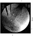
- X-ray technicianswill usually rotate the C-arm image so that “up” on the image correlates to “superior” on the anatomy—if one assumes that this is true, then one can just look at the left and right sides of the beam cone to see which is darker on average. If the left side of the X-ray image is darker, then the image is of the left hip. If the left side of the X-ray image is lighter, then the image is of the right hip. This is because bone tissue absorbs X-rays and appears darker on the image. Air or soft tissue attenuates less X-rays, so they appear much lighter on the image. See FIG. 29 , where the left side 165 of the X-ray image is darker and the right side 170 of the X-ray image is lighter.
- the Light/Dark Side methodis not useful if the C-arm image is not rotated so that “up” on the image correlates to “superior” on the anatomy.
- femoral head hint 155 and femoral neck hint 160are used to determine whether the X-ray image is of the left hip or the right hip. More particularly, and looking now at FIG. 30 , the horizontal distance 175 from femoral head hint 155 and femoral neck hint 160 is determined. If femoral head hint 155 is to the left of femoral neck hint 160 , the X-ray image is of the left hip, if femoral head hint 155 is to the right of femoral neck hint 160 , the X-ray image is of the right hip.
- computer visual guidance system 125can use the location and orientation of the instrument to determine if the hip being imaged is a left hip or a right hip.
- instrumentsare introduced on the lateral side of the femoral head, with a trajectory from lateral to medial. Given this fact, computer visual guidance system 125 can first locate an instrument in the X-ray image, then identify the location and orientation of the instrument within the X-ray image so as to determine if the hip being imaged is a left hip or a right hip.
- Step 7Provide Clues for where to Create the Search Area for Femoral Head
- the next stepis to provide computer visual guidance system 125 with clues for where to start its analysis of the anatomy. This is desirable because processing will run faster if the analysis starts with an intelligent “guess” of the anatomy to center on.
- femoral head hint 155at the center of the femoral head
- Another way to intelligently guess where to start the analysisis to use the tips of the medical instruments present in the surgical field. Even if one does not know what the medical instruments are, they typically have an elongated shape and a Hough transform can be used to look for parallel lines (which indicate the profiles of the elongated medical instruments).
- the center of the femoral headwill typically be somewhere near the tips of the medical instruments, at least within one diameter of the largest possible femoral head, and usually in front of the medical instruments. If two medical instruments are present in the X-ray image (there typically will be), then the estimate of where to start the analysis becomes more accurate, since one can limit the region of interest to the intersection of the parallel lines of the medical instruments (i.e., the side profiles of the medical instruments). See FIG. 31 , where the tips of burr 145 and scope 150 are used to provide a clue as to where to start the analysis of the anatomy.
- Step 8Determine the Search Area for Femoral Head
- the next stepis to determine the search area. This is desirable because the more pixels that computer visual guidance system 125 has to look at, the longer the search time. So anything that can reduce the search area will speed up processing time.
- the image area outside the beam coneis eliminated.
- Most C-armsprovide a circular image on a black background. This is because the beam of X-rays is arranged in a cone, and is received by a circular image intensifier. It is not necessary to search the black areas of the X-ray image. In fact, it can be assumed that the femoral head will be mostly, if not entirely, inside the beam cone of the X-ray image. It is possible, therefore, to narrow the search for the femoral head to those structures that have a center point well inside the beam cone.
- a search areais defined around the clue from Step 7. See FIG. 32 , where a search area 180 is shown defined around the clue from Step 7.
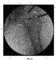
- Step 9Conduct Edge Detection
- the next stepis to conduct edge detection of the relevant anatomy to determine the edges of the femoral head.
- edge detectionThere are multiple ways to carry this out including industry standard methods such as canny edge detection. See FIG. 33 , which shows edge detection for the femoral head.
- Step 10Find/Remove Instrument Edges
- Step 11Find the Femoral Head
- the next stepis to find the femoral head.
- find the femoral headThere are multiple ways to find the femoral head.
- the simplest method to find the femoral headis to use a Hough transform, looking for circles. These circles are limited in the range of the smallest and largest possible femoral heads.
- the Hough transformproduces a list of possible answers and the best possible answer is selected. This method works well in high quality images, although it can fail in low quality images. See FIG. 33A , which shows circle 5 encircling the femoral head.
- a center pointis picked, and then computer visual guidance system 125 starts tracing along lines looking for edges between the minimum and maximum possible radii (which correlates to the smallest and largest possible femoral head).
- computer visual guidance system 125selects the point that has the strongest edge in each ray, and then checks to see if these points end up in a circle. Then another point is selected, and the process is repeated. This is done iteratively until the best point is found, using previous points as a guide for where to look next.
- ASMActive Shape Modeling
- ASMActive Shape Modeling
- computer visual guidance system 125is trained with hundreds (or thousands) of hip X-ray images, where dozens of specific locations are selected around the profile of the femoral head. Then computer visual guidance system 125 is presented with a new X-ray image and a “good guess” as to where the femur is in that image. This “good guess” does not have to be highly accurate, it simply needs to be in the right ballpark. Step 7 (provide clues where to start) must be completed for this approach to be used.
- the ASM processwill overlay a set of points in the shape of a femur and then work to reduce the error between the set of points and the strong edges in the image. See FIG. 34 .
- the ASM processis completed by the computer visual guidance system, one can just select the specific points from the femur and calculate a best-fit circle for the femoral head.
- Step 12Find the Femoral Neck and its Mid-line
- the next stepis to find the femoral neck and its mid-line.
- find the femoral neck and its mid-lineThere are multiple ways to find the femoral neck and its mid-line.
- computer visual guidance system 125sweeps a box around the femoral head (where the box has its mid-line passing through the center of the femoral head) and looks to see if the sides of that box line up with the edges of the femoral neck (edge detection is used to identify the edges of the femoral neck). This is repeated for boxes of multiple sizes. The box that lines up with the strongest edges of the femoral neck is chosen. The center of the box is then used to determine the mid-line of the femoral neck.
- ASMActive Shape Modeling
- This approachworks in a manner similar to how ASM is used to find the femoral head, except that one selects the points on the femoral neck, then determines a mid-line, and then finds the average location of those points to determine the mid-line of the femoral neck.
- Step 13Find where the Femoral Neck Stops Being Round and the Cam Pathology Starts
- the next stepis to find where the femoral head stops being round and the cam pathology starts.
- the strongest edges (e.g., as shown at 182 in FIG. 33 ) of the bone surfaceare traced (e.g., using the results of edge detection) until a deviation from the circle around the femoral head is found.
- the tracingdoes not need to include the entire femoral head but rather just the region of interest.
- the region of intereststarts at a location on the femoral head which is approximately 110 degrees from the femoral neck mid-line in the superior direction (in other words, for a right hip as shown in FIG. 35 , between the 9 o'clock position and the 12 noon position).
- a threshold level for the deviationcan be used to ignore small deviations which may be a result of imperfections in edge detection rather than being the actual cam pathology.
- the deviation thresholdis a small percentage of the femoral head diameter, for example, 3-6% of the femoral head diameter, and more preferably 4% of the femoral head diameter.
- the deviation thresholdis a fixed value, for example, 0.5-2 mm, and more preferably 1 mm.
- Step 14Measure the Alpha Angle and Input the Target Alpha Angle
- the next stepis to measure the Alpha Angle.
- the Alpha Angle 35is calculated as the angle between these image features:
- the Alpha Angleis the angle measured between (i) the line 15 originating at the center of the femoral head and extending along the center of the femoral neck, and (ii) the line 25 originating at the center of the femoral head and passing through the location at the start of the cam pathology.
- This Alpha Anglecan be annotated onto the X-ray image, as shown in FIG. 36 , along with circle 5 enscribing the femoral head and line 15 showing the center of the femoral neck, and this annotated X-ray image can be presented to the surgeon on computer visual guidance system 125 or monitor 110 .
- the surgeonmay also find it useful to know the size of the cam pathology by way of the angle subtended between the Alpha Angle and the target Alpha Angle (i.e., the desired Alpha Angle).
- the target Alpha Angleis established, either with input from the surgeon or another source.
- the computer visual guidance system 125displays the target Alpha Angle (line 190 in FIG. 36 ).
- the greater the difference between the current Alpha Angle line 25 and the target Alpha Angle line 190the larger the cam pathology and hence more bone removal is required. See FIG. 36 , where the target Alpha Angle of 42 degrees is presented as line 190 on the X-ray image, along with the actual Alpha Angle line 25 , circle 5 enscribing the femoral head, and line 15 showing the center of the femoral neck.
- Step 15Compute the Resection Curve
- the resection curve 195comprises a first resection curve 200 adjacent to the femoral head, and a second resection curve 205 adjacent to the femoral neck.
- First resection curve 200starts at the Alpha Angle Line 25 and ends at the target Alpha Angle line 190 . Note that first resection curve 200 is simply the continuation of the circle of the femoral head.
- Second resection curve 205starts at the end of first resection curve 200 (i.e., at the target Alpha Angle line 190 ) and extends down the neck.
- second resection curve 205is calculated as follows. First, and looking now at FIG. 38 , the start point 210 and end point 215 of second resection curve 205 are found. As seen in FIG. 38 , start point 210 is the point at which target Alpha Angle line 190 intersects the femoral head circle. Note that start point 210 is also the endpoint of first section curve 200 . In one embodiment, end point 215 is found by determining the shortest distance between femoral neck hint 160 and the neck boundary: this shortest line of intersection defines end point 215 . Then a spline 220 is generated, using start point 210 , end point 215 and a control point 225 for spline 220 .
- spline 220is second resection curve 205 .
- Control point 225 for spline 220may be generated in a variety of ways.
- control point 225may be obtained by studying a set of “normal” patient anatomies and determining an appropriate control point for a given start point 210 and a given endpoint 215 in order to provide a spline approximating a normal anatomy.
- control point 225may be obtained by polling a group of experts to determine an appropriate control point for a given start point 210 and a given endpoint 215 in order to provide a spline approximating a normal anatomy.
- spline 220i.e., second resection curve 205
- second resection curve 205is concatenated to the end of first resection curve 200 so as to produce the overall resection curve 195 .
- the depth of resectioni.e., the thickness of bone to be removed
- the depth of resectioncan also be measured and then displayed to the user, using the calibrations of pixel size previously conducted.
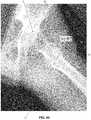
- the numeric value of the Alpha Anglecan be presented on the X-ray image (see, for example, FIG. 37 where the numeric value of “55” is placed on the X-ray image to show that the Alpha Angle is 50 degrees), and the numeric value of the target Alpha Angle can be presented on the X-ray image (see, for example, FIG. 37 where the numeric value “42” is placed on the X-ray image to show the target Alpha Angle is 42 degrees).
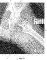
- the next stepis to draw extra features on the X-ray image.
- computer visual guidance system 125is configured to draw the ruler just below the cam pathology, which will show the surgeon how much bone they have to remove. See FIG. 39 .
- computer visual guidance system 125When computer visual guidance system 125 draws the target line for the target Alpha Angle, computer visual guidance system 125 can add false color to the triangular region 230 ( FIG. 40 ) denoting the cam pathology which is to be removed (i.e., the bone which is located between the start of the cam and the target Alpha Angle).
- multiple C-Arm images(e.g., with the C-arm manipulated through a number of planes) can be acquired and the computer system can generate the false color 3D cam pathology as a resulting set of false color 2D cam pathology images displayed at the same time for the surgeon.
- 2D images acquired intra-operatively by a C-arm X-ray machine 115can be “merged” with one another so as to form a pseudo-3D model of the cam pathology.
- C-arm X-ray machine 115is oriented in multiple planes such that multiple 2D images of the cam pathology are acquired.
- Computer visual guidance system 125then merges the acquired 2D images so as to form a partial 3D model of the cam pathology.
- a 2D outline 235 ( FIG. 41 ) of the cam pathologyis created with the 2D images.
- the surgeoncan adjust the locations of the previously-determined femoral head, the previously-determined femoral neck, the previously-determined measured Alpha Angle, the previously-determined target Alpha Angle, the previously-determined resection curve start point, and the previously-determined resection curve end point, by simply dragging any of those elements to a desired location using the annotated image displayed by computer visual guidance system 125 (e.g., the touchscreen of a tablet device). If the user does adjust one or more of these locations, computer visual guidance system 125 will automatically re-compute the anatomical measurements and resection curve by utilizing the user-specified locations in place of the automatically-calculated locations.
- computer visual guidance system 125e.g., the touchscreen of a tablet device
- Subsequent images that are processedmay or may not take into account the user-specified location changes to improve the overall accuracy and robustness of the measurements and resection curve location. For example, if the user specifies a larger femoral head radius, the femoral head detection algorithm may give preference to a larger detected femoral head. Also, if the user manually adjusts the resection curve end point, subsequent processed images may also provide a resection end point that is closer to the user's manual modification, i.e., if the user moves the resection end point more proximal, then the following images might also place the resection end point more proximal than would be the case by default.
- a good method for retaining relative distances between imageswould be to retain distances relative to the size of the femoral head.
- a distance of “1.5 times the femoral head radius”should be a relatively constant distance between processed images, regardless of changes in zooming and rotation of the femur (as the femoral head radius is approximately spherical and should retain a relatively constant radius regardless of how it is imaged).
- the surgeoncan iteratively check the progress of the boney resection by periodically updating the intra-operative X-ray image and the assessment, by computer visual guidance system 125 , of the measurements associated with the bony pathology.
- the surgeonperiodically updates the intraoperative C-arm image.
- computer visual guidance system 125automatically re-assesses the cam pathology (i.e., it automatically recalculates the Alpha Angle and the resection curve, etc.), and automatically annotates the X-ray image to show how the Alpha Angle changes from the original Alpha Angle toward the target Alpha Angle.
- This approachprovides iterative guidance to the surgeon, enabling the surgeon to proceed with greater confidence as the cam pathology is reduced and, ultimately, reduces the possibility of under-resection of the cam pathology which could necessitate revision hip arthroscopy.
- the additional X-ray images acquired for this iterative process of repeatedly assessing the cam pathology as the surgery progressesmay be done with the patient's leg and the C-arm X-ray machine remaining in the same position so as to provide updated assessments of the boney resection with the same X-ray projection; or the patient's leg may be re-positioned, and/or the C-arm X-ray machine moved, between X-ray images so as to provide updated assessments of the boney resection with differing X-ray projections.
- Computer visual guidance system 125can be configured to provide step-by-step guidance to the surgeon to make sure that documenting images are captured at the appropriate points along the procedure, preferably along with automatic measurements.
- computer visual guidance system 125will never be 100% accurate or that the surgeon may make different choices for their patient based on experience and their understanding of the patient's condition. Since images end up being part of a medical record, computer visual guidance system 125 is configured to require manual confirmation from the surgeon before saving an image to the medical record. These interactions may be done in the sterile field through a variety of input devices including but not limited to:
- FIG. 48is a schematic view of an acetabulum 240 comprising an acetabular cup 245 for receiving femoral head 10 of femur 60 , and illustrates a pincer-type femoroacetabular impingement site 50 which needs to be debrided in order to treat the pincer-type femoroacetabular impingement.
- the present inventioncomprises the provision and use of a novel computer visual guidance system which analyzes an X-ray image (e.g., an intra-operative C-arm X-ray image) to automatically measure features of the hip, such as the pincer pathology (e.g., by using a “Center Edge Angle” calculation, see below), and then annotates the X-ray image for use by the surgeon in treating the pincer pathology.
- the purpose of this inventionis to guide the surgeon to an optimal resection of the pincer pathology which is causing the impingement.
- arthroscopic resectionsare currently “eye-balled” and the surgeon has no objective way to define completion of the boney resection.
- the present inventionaddresses this problem by providing means which automatically analyze an X-ray image with respect to a pincer pathology and then automatically annotates the X-ray image with guidance features which can be used by the surgeon in treating the pincer pathology.
- the present inventioncomprises a series of steps which start with an X-ray image and yields measurement of a feature of the hip (e.g., the Center Edge Angle) and an annotation correctly shown onto that X-ray image for the surgeon to be able to assess the pathology and progress towards proper resection.
- a feature of the hipe.g., the Center Edge Angle
- the inventionutilizes the aforementioned methodology for treating a cam pathology, except that it is modified for treating a pincer pathology. More particularly, Steps 11-14 in the cam pathology procedure ( FIG. 20 ) are replaced by the following Steps 11-14 for the pincer pathology treatment.
- Step 11Find the Transverse Pelvic Axis
- the transverse pelvic axis 250is located using standard image processing techniques, e.g., by drawing a line between the inferior apexes 255 of the ischium bones (or, alternatively, by drawing a line between the center of both femoral heads).
- Step 12Find the Perpendicular to the Transverse Pelvic Axis which Extends Through the Center of the Femoral Head
- Step 13Find the Line which Extends from the Lateral Acetabular Edge to the Center of the Femoral Head
- the lateral acetabular edge line 265which extends from the lateral edge 270 of the acetabular rim to the center 185 of the femoral head is located using standard image processing techniques, e.g., in an AP (Anterior-Posterior) view, by creating a line which passes from the lateral sourcil (the most supereolateral aspect of the sclerotic weight-bearing zone of the acetabulum) to the center of the femoral head.
- APanterior-Posterior
- the Center Edge Angle 55i.e., the angle between the perpendicular 260 and the lateral acetabular edge line 265 ) is calculated, e.g., by measuring the angle formed between the portion of the perpendicular 260 on the superior side of the femoral head and the lateral acetabular edge line 265 .
- the Center Edge Angle of a “normal” personis typically between about 25 and about 35 degrees (i.e., the target Center Edge Angle is normally approximately 25 degrees to approximately 35 degrees).
- Both the actual Center Edge Angle and the target Center Edge Anglecan be automatically computed by computer visual guidance system 125 from an X-ray image and these features automatically annotated on the X-ray image for display to the surgeon. Furthermore, the difference between the actual Center Edge Angle and the target Center Edge Angle (i.e., the resection section) can be automatically identified by computer visual guidance system 125 and automatically annotated on the X-ray image for display to the surgeon.
- Connectivity between the computer visual guidance system and the hip distraction equipmentcan provide medical personnel with useful information before, during and after a surgical procedure.
- the computer visual guidance systemcan be used to guide the medical personnel through the proper set-up of the distraction equipment, including assembly of the distraction equipment, attachment of the distraction equipment to the surgical bed, placement of other equipment in the surgical suite, proper patient positioning and attachment to the distraction equipment, information on use of the distraction equipment during the procedure, cleaning information, storage information and disassembly instructions.
- This informationmay be presented as a step-based system with prompts, or as a menu-driven system, or as a question-driven system, that provides users with only the requested information.
- the informationmay be presented as text, images (including video) and/or animation (including video), as appropriate, to convey the needed information.
- the computer visual guidance systemmay be used in conjunction with sensors.
- the computer visual guidance systemcan utilize information about the distraction equipment and provide feedback to medical personnel.
- a set of sensors in the distraction equipmentcan detect the position of the distraction equipment in space.
- Information about the position of the heel or foot of the patientwould be particularly useful as it is typically the attachment point for the patient to the distraction equipment.
- Additional information about the position of the patient's hipcould be provided manually or through coordination with the C-arm X-ray device. Knowing this information would then provide information about the relative position of the patient's leg, and specifically their hip (e.g., whether it is in flexion, extension, abduction, adduction, internal or external rotation).
- Sensorscan also be used to detect when traction is applied, either by measuring the position of the heel relative to the hip, or by a measurement of force.
- image analysiscan be done to determine if the acetabulum and femoral head are dislocated allowing the deduction of whether traction is applied. This could provide medical personnel with feedback on the amount of tension applied to the patient, its direction of force (vector), and duration of the application of traction.
- the computer visual guidance systemcan prompt medical personnel on how to position the patient for optimal resection.
- the positioning of the hip and leg during this part of the procedurecan be driven by pre-operative planning software that has been created to analyze and plan the resection.
- This pre-operative softwaremay generate a series of images showing patient hip positions so that the surgeon and operative team can fully visualize the pathology, in particular the cam pathology.
- novel computer visual guidance system of the present inventionmay be used for applications other than the specific Alpha Angle measurements and/or Center Edge Angle measurements discussed herein as related to the treatment of the hip joint.
- novel computer visual guidance system of the present inventionmay be used to measure other parameters in order to guide debridement of the femur and/or acetabulum during treatment of femoroacetabular impingement.
- the novel computer visual guidance system of the present inventionmay be used to guide debridement in joints other than the hip joint (e.g., to guide debridement of a surface of a humerus in order to prepare that surface for re-attachment of a torn rotator cuff, or to guide debridement of a surface of a bone in spinal surgery, etc.).
- novel computer visual guidance system of the present inventionmay be used in non-arthroscopic procedures.
Landscapes
- Health & Medical Sciences (AREA)
- Engineering & Computer Science (AREA)
- Life Sciences & Earth Sciences (AREA)
- Surgery (AREA)
- Nuclear Medicine, Radiotherapy & Molecular Imaging (AREA)
- General Health & Medical Sciences (AREA)
- Medical Informatics (AREA)
- Biomedical Technology (AREA)
- Veterinary Medicine (AREA)
- Public Health (AREA)
- Animal Behavior & Ethology (AREA)
- Molecular Biology (AREA)
- Heart & Thoracic Surgery (AREA)
- Theoretical Computer Science (AREA)
- Physics & Mathematics (AREA)
- Robotics (AREA)
- General Physics & Mathematics (AREA)
- Radiology & Medical Imaging (AREA)
- Oral & Maxillofacial Surgery (AREA)
- Dentistry (AREA)
- Orthopedic Medicine & Surgery (AREA)
- Human Computer Interaction (AREA)
- Pathology (AREA)
- Quality & Reliability (AREA)
- Computer Vision & Pattern Recognition (AREA)
- Apparatus For Radiation Diagnosis (AREA)
- Surgical Instruments (AREA)
Abstract
Description
- (i) receive a 2D image of the bony pathology from a source;
- (ii) automatically analyze the 2D image so as to determine at least one measurement with respect to the bony pathology;
- (iii) automatically annotate the 2D image with at least one annotation relating to the at least one measurement determined with respect to the bony pathology so as to create an annotated 2D image; and
- (iv) display the annotated 2D image to the surgeon so as to guide the surgeon through the arthroscopic debridement of the bony pathology;
- perform a radial blur at each point before running edge detection—this will obscure hard edges that are not circles;
- look for strong edges, and check their gradients to see if they are dark→light (femoral head) or light→dark (acetabulum); and
- look for partial circles, rather than full circles—the correct outline of the femoral head will not have an edge where the femoral neck connects to the femoral head.
- the
center line 15 of the femoral neck; - the
center point 185 of the femoral head; and - the location of the start of the
cam pathology 30 at the femoral head/neck junction.
- the
circle 5 inscribing the femoral head;- centerpoint185 of the circle inscribing the femoral head;
line 15 originating at the center of the femoral head and extending along the centerline of the femoral neck;Alpha Angle line 25 originating at the center of the femoral head and passing through the location at the start of the cam pathology;line 190 showing the target Alpha Angle; andresection curve 195.
- wireless mouse (sterile draped)
- wireless accelerometer with buttons (sterile draped)
- remote control (sterile draped)
- tablet (sterile draped)
- camera buttons.
Claims (29)
Priority Applications (4)
| Application Number | Priority Date | Filing Date | Title |
|---|---|---|---|
| US15/818,394US10918398B2 (en) | 2016-11-18 | 2017-11-20 | Method and apparatus for treating a joint, including the treatment of cam-type femoroacetabular impingement in a hip joint and pincer-type femoroacetabular impingement in a hip joint |
| US17/143,091US11612402B2 (en) | 2016-11-18 | 2021-01-06 | Method and apparatus for treating a joint, including the treatment of cam-type femoroacetabular impingement in a hip joint and pincer-type femoroacetabular impingement in a hip joint |
| US18/190,956US12336723B2 (en) | 2016-11-18 | 2023-03-27 | Method and apparatus for treating a joint, including the treatment of cam-type femoroacetabular impingement in a hip joint and pincer-type femoroacetabular impingement in a hip joint |
| US18/797,873US20240390017A1 (en) | 2016-11-18 | 2024-08-08 | Method and apparatus for treating a joint, including the treatment of cam-type femoroacetabular impingement in a hip joint and pincer-type femoroacetabular impingement in a hip joint |
Applications Claiming Priority (2)
| Application Number | Priority Date | Filing Date | Title |
|---|---|---|---|
| US201662423890P | 2016-11-18 | 2016-11-18 | |
| US15/818,394US10918398B2 (en) | 2016-11-18 | 2017-11-20 | Method and apparatus for treating a joint, including the treatment of cam-type femoroacetabular impingement in a hip joint and pincer-type femoroacetabular impingement in a hip joint |
Related Child Applications (1)
| Application Number | Title | Priority Date | Filing Date |
|---|---|---|---|
| US17/143,091ContinuationUS11612402B2 (en) | 2016-11-18 | 2021-01-06 | Method and apparatus for treating a joint, including the treatment of cam-type femoroacetabular impingement in a hip joint and pincer-type femoroacetabular impingement in a hip joint |
Publications (2)
| Publication Number | Publication Date |
|---|---|
| US20180140309A1 US20180140309A1 (en) | 2018-05-24 |
| US10918398B2true US10918398B2 (en) | 2021-02-16 |
Family
ID=62144126
Family Applications (4)
| Application Number | Title | Priority Date | Filing Date |
|---|---|---|---|
| US15/818,394ActiveUS10918398B2 (en) | 2016-11-18 | 2017-11-20 | Method and apparatus for treating a joint, including the treatment of cam-type femoroacetabular impingement in a hip joint and pincer-type femoroacetabular impingement in a hip joint |
| US17/143,091Active2038-07-20US11612402B2 (en) | 2016-11-18 | 2021-01-06 | Method and apparatus for treating a joint, including the treatment of cam-type femoroacetabular impingement in a hip joint and pincer-type femoroacetabular impingement in a hip joint |
| US18/190,956ActiveUS12336723B2 (en) | 2016-11-18 | 2023-03-27 | Method and apparatus for treating a joint, including the treatment of cam-type femoroacetabular impingement in a hip joint and pincer-type femoroacetabular impingement in a hip joint |
| US18/797,873PendingUS20240390017A1 (en) | 2016-11-18 | 2024-08-08 | Method and apparatus for treating a joint, including the treatment of cam-type femoroacetabular impingement in a hip joint and pincer-type femoroacetabular impingement in a hip joint |
Family Applications After (3)
| Application Number | Title | Priority Date | Filing Date |
|---|---|---|---|
| US17/143,091Active2038-07-20US11612402B2 (en) | 2016-11-18 | 2021-01-06 | Method and apparatus for treating a joint, including the treatment of cam-type femoroacetabular impingement in a hip joint and pincer-type femoroacetabular impingement in a hip joint |
| US18/190,956ActiveUS12336723B2 (en) | 2016-11-18 | 2023-03-27 | Method and apparatus for treating a joint, including the treatment of cam-type femoroacetabular impingement in a hip joint and pincer-type femoroacetabular impingement in a hip joint |
| US18/797,873PendingUS20240390017A1 (en) | 2016-11-18 | 2024-08-08 | Method and apparatus for treating a joint, including the treatment of cam-type femoroacetabular impingement in a hip joint and pincer-type femoroacetabular impingement in a hip joint |
Country Status (6)
| Country | Link |
|---|---|
| US (4) | US10918398B2 (en) |
| EP (1) | EP3541270A4 (en) |
| CN (1) | CN110177492A (en) |
| AU (1) | AU2017362768A1 (en) |
| CA (1) | CA3043744A1 (en) |
| WO (1) | WO2018094348A1 (en) |
Cited By (4)
| Publication number | Priority date | Publication date | Assignee | Title |
|---|---|---|---|---|
| US20220233159A1 (en)* | 2019-05-29 | 2022-07-28 | Industrial Cooperation Foundation Chonbuk National University | Medical image processing method and device using machine learning |
| US11957418B2 (en) | 2018-01-29 | 2024-04-16 | Stryker Corporation | Systems and methods for pre-operative visualization of a joint |
| US12256996B2 (en) | 2020-12-15 | 2025-03-25 | Stryker Corporation | Systems and methods for generating a three-dimensional model of a joint from two-dimensional images |
| US12336723B2 (en) | 2016-11-18 | 2025-06-24 | Stryker Corporation | Method and apparatus for treating a joint, including the treatment of cam-type femoroacetabular impingement in a hip joint and pincer-type femoroacetabular impingement in a hip joint |
Families Citing this family (17)
| Publication number | Priority date | Publication date | Assignee | Title |
|---|---|---|---|---|
| US11382816B2 (en) | 2015-06-05 | 2022-07-12 | Stryker Corporation | Surgical table and accessories to facilitate hip arthroscopy |
| CA3052793A1 (en) | 2017-02-06 | 2018-08-09 | Stryker Corp. | Distraction frame for effecting hip distraction |
| EP3576687B1 (en) | 2017-02-06 | 2025-07-02 | Stryker Corporation | Method and apparatus for supporting and stabilizing a patient during hip distraction |
| CN110891488B (en)* | 2017-03-09 | 2023-05-23 | 史密夫和内修有限公司 | sagittal rotation determined |
| US10820837B2 (en)* | 2018-04-09 | 2020-11-03 | Siemens Healthcare Gmbh | System and method for angle measurements using magnetic resonance images |
| US11007031B2 (en)* | 2018-08-14 | 2021-05-18 | Verb Surgical Inc. | Setup of surgical robots using an augmented mirror display |
| CN109272488B (en)* | 2018-08-16 | 2021-08-20 | 深圳大学 | A method and device for evaluating the change of motion force of human hip joint |
| US11452566B2 (en)* | 2018-12-21 | 2022-09-27 | Intellijoint Surgical Inc. | Pre-operative planning for reorientation surgery: surface-model-free approach using simulated x-rays |
| US11285064B2 (en) | 2019-02-07 | 2022-03-29 | Stryker Corporation | Table mount for a touchscreen device |
| CN110660480B (en)* | 2019-09-25 | 2023-05-26 | 上海交通大学 | Auxiliary diagnosis method and system for spinal dislocation |
| SE543797C2 (en)* | 2019-10-29 | 2021-07-27 | Ortoma Ab | Method for Planning an Orthopedic Procedure |
| CN110992316B (en)* | 2019-11-18 | 2023-05-30 | 湖北工业大学 | Visualization Method of Brain MRI Abnormal Images Based on 2D CAM |
| CN111358563B (en)* | 2020-03-11 | 2021-09-03 | 上海交通大学 | Hip arthroscope auxiliary robot system based on cooperative mechanical arm and control method |
| CN115701948A (en) | 2020-08-04 | 2023-02-14 | 史赛克公司 | System and method for visualizing a trajectory with a surgical instrument |
| US11564855B2 (en)* | 2020-09-28 | 2023-01-31 | Stryker Corporation | Systems and methods for supporting and stabilizing a patient during hip distraction |
| WO2023244566A2 (en) | 2022-06-13 | 2023-12-21 | Stryker Corporation | Trajectory guidance of hand-held surgical tools during a surgical procedure |
| CN118151805B (en)* | 2024-05-10 | 2024-09-03 | 杭州三坛医疗科技有限公司 | Software interface interaction method based on hip joint file grinding control |
Citations (100)
| Publication number | Priority date | Publication date | Assignee | Title |
|---|---|---|---|---|
| US5862249A (en) | 1995-12-01 | 1999-01-19 | Eastman Kodak Company | Automated method and system for determination of positional orientation of digital radiographic images |
| US6161080A (en) | 1997-11-17 | 2000-12-12 | The Trustees Of Columbia University In The City Of New York | Three dimensional multibody modeling of anatomical joints |
| US6205411B1 (en) | 1997-02-21 | 2001-03-20 | Carnegie Mellon University | Computer-assisted surgery planner and intra-operative guidance system |
| DE10057023A1 (en) | 2000-11-17 | 2002-06-06 | Siemens Ag | Method and appliance for identifying correct alignment of fractured bones by superimposition of templates on images of those bones |
| US20030176783A1 (en) | 2000-07-06 | 2003-09-18 | Qingmao Hu | Method and device for impingement detection |
| US6697664B2 (en) | 1999-02-10 | 2004-02-24 | Ge Medical Systems Global Technology Company, Llc | Computer assisted targeting device for use in orthopaedic surgery |
| US20050096535A1 (en)* | 2003-11-04 | 2005-05-05 | De La Barrera Jose Luis M. | System and method of registering image data to intra-operatively digitized landmarks |
| US20070016008A1 (en) | 2005-06-23 | 2007-01-18 | Ryan Schoenefeld | Selective gesturing input to a surgical navigation system |
| US7167738B2 (en) | 2000-08-01 | 2007-01-23 | Stryker Leibinger Gmbh & Co., Kg | Method for navigating in the interior of the body using three-dimensionally visualized structures |
| US20070129630A1 (en) | 2005-12-07 | 2007-06-07 | Shimko Daniel A | Imaging method, device and system |
| US20070135706A1 (en) | 2005-12-13 | 2007-06-14 | Shimko Daniel A | Debridement method, device and kit |
| EP1844726A2 (en) | 2003-01-30 | 2007-10-17 | Surgical Navigation Technologies, Inc. | A display, a navigation system and a method for guiding a medical device to a target |
| US20070260256A1 (en) | 2006-05-05 | 2007-11-08 | Beaule Paul E | Surgical instrument tray, hip resurfacing kit, and method of resurfacing a femoral head to preserve femoral head vascularity |
| US20080300478A1 (en) | 2007-05-30 | 2008-12-04 | General Electric Company | System and method for displaying real-time state of imaged anatomy during a surgical procedure |
| US20090000626A1 (en) | 2002-03-06 | 2009-01-01 | Mako Surgical Corp. | Haptic guidance system and method |
| US20090209851A1 (en) | 2008-01-09 | 2009-08-20 | Stryker Leibinger Gmbh & Co. Kg | Stereotactic computer assisted surgery method and system |
| US7643862B2 (en) | 2005-09-15 | 2010-01-05 | Biomet Manufacturing Corporation | Virtual mouse for use in surgical navigation |
| US20100049493A1 (en) | 2008-08-20 | 2010-02-25 | Martin Haimerl | Planning assistance for correcting joint elements |
| US7783008B2 (en) | 2007-03-30 | 2010-08-24 | General Electric Company | Digital radiograph patient positioning system and method |
| US7949386B2 (en) | 2006-03-21 | 2011-05-24 | A2 Surgical | Computer-aided osteoplasty surgery system |
| US20110190774A1 (en) | 2009-11-18 | 2011-08-04 | Julian Nikolchev | Methods and apparatus for performing an arthroscopic procedure using surgical navigation |
| US20110213428A1 (en) | 2003-11-25 | 2011-09-01 | Conformis, Inc. | Patient Selectable Joint Arthroplasty Devices and Surgical Tools |
| US20110213379A1 (en) | 2010-03-01 | 2011-09-01 | Stryker Trauma Gmbh | Computer assisted surgery system |
| US8014984B2 (en) | 2007-03-06 | 2011-09-06 | The Cleveland Clinic Foundation | Method and apparatus for preparing for a surgical procedure |
| US20110238431A1 (en) | 2010-03-23 | 2011-09-29 | Robert Cionni | Surgical Console Information Management |
| US20110270295A1 (en) | 2010-02-17 | 2011-11-03 | Reprise Technologies, Llc | System and method for image-guided arthroscopy |
| US8052623B2 (en) | 2007-06-15 | 2011-11-08 | Brainlab Ag | Computer-assisted joint analysis using surface projection |
| US20110301654A1 (en) | 2008-11-05 | 2011-12-08 | Imperial Innovations Ltd. | Hip resurfacing |
| WO2011158117A2 (en) | 2010-06-16 | 2011-12-22 | A2 Surgical | Method and system of automatic determination of geometric elements characterizing a bone deformation from 3d image |
| US8090166B2 (en) | 2006-09-21 | 2012-01-03 | Surgix Ltd. | Medical image analysis |
| US8152816B2 (en) | 2007-06-15 | 2012-04-10 | Brainlab Ag | Computer-assisted planning method for correcting changes in the shape of joint bones |
| US20120271147A1 (en) | 2011-04-22 | 2012-10-25 | New York University | Apparatus, method, and computer-accessible medium for b1-insensitive high resolution 2d t1 mapping in magnetic resonance imaging |
| WO2012149964A1 (en) | 2011-05-04 | 2012-11-08 | Stryker Trauma Gmbh | Systems and methods for automatic detection and testing of images for clinical relevance |
| US8328816B2 (en) | 2005-07-20 | 2012-12-11 | Wright Medical Technology, Inc. | Femoral gauge |
| US8369593B2 (en) | 2007-12-21 | 2013-02-05 | Siemens Medical Solutions Usa, Inc. | Systems and methods for robust learning based annotation of medical radiographs |
| US20130114866A1 (en) | 2011-11-08 | 2013-05-09 | Mako Surgical Corporation | Computer-Aided Planning with Dual Alpha Angles in Femoral Acetabular Impingement Surgery |
| EP2618313A1 (en) | 2012-01-19 | 2013-07-24 | Clinical Graphics B.V. | Process to generate a computeraccessible medium comprising information on the functioning of a joint |
| US20130191099A1 (en) | 2012-01-19 | 2013-07-25 | Peter Roelof Krekel | Process for generating a computer-accessible medium including information on the functioning of a joint |
| US20130211386A1 (en) | 2010-07-16 | 2013-08-15 | Stryker Trauma Gmbh | Surgical targeting system and method |
| US20130211408A1 (en) | 2012-02-08 | 2013-08-15 | Jens Kather | Curved Arthroscopic Burr and Measurement Instrumentation |
| US20130211232A1 (en) | 2012-02-01 | 2013-08-15 | The Johns Hopkins University | Arthroscopic Surgical Planning and Execution with 3D Imaging |
| US8594397B2 (en) | 2008-05-15 | 2013-11-26 | Brainlab Ag | Joint reconstruction planning using model data |
| WO2013174401A1 (en) | 2012-05-23 | 2013-11-28 | Stryker Trauma Gmbh | Entry portal navigation |
| US20130314440A1 (en) | 2012-05-23 | 2013-11-28 | Stryker Trauma Gmbh | Virtual 3d overlay as reduction aid for complex fractures |
| WO2013174402A1 (en) | 2012-05-23 | 2013-11-28 | Stryker Trauma Gmbh | Locking screw length measurement |
| US20130315371A1 (en) | 2012-05-23 | 2013-11-28 | Stryker Trauma Gmbh | Bone density measurement |
| US8611697B2 (en)* | 2007-06-21 | 2013-12-17 | Surgix Ltd. | System for measuring the true dimensions and orientation of objects in a two dimensional image |
| US8679125B2 (en) | 2010-09-22 | 2014-03-25 | Biomet Manufacturing, Llc | Robotic guided femoral head reshaping |
| WO2014048447A1 (en) | 2012-09-27 | 2014-04-03 | Stryker Trauma Gmbh | Rotational position determination |
| US8694075B2 (en) | 2009-12-21 | 2014-04-08 | General Electric Company | Intra-operative registration for navigated surgical procedures |
| US8696603B2 (en) | 2008-12-04 | 2014-04-15 | Fujifilm Corporation | System for measuring space width of joint, method for measuring space width of joint and recording medium |
| US8702805B2 (en) | 2008-07-21 | 2014-04-22 | Harutaro Trabish | Acetabulum surgical resurfacing aid |
| US8715289B2 (en) | 2011-04-15 | 2014-05-06 | Biomet Manufacturing, Llc | Patient-specific numerically controlled instrument |
| US20140187908A1 (en) | 2012-11-24 | 2014-07-03 | Jutta Ellermann | System and Method for Patient-Specific Planar Visualization of Volumetric MRI Data |
| US8831324B2 (en) | 2012-10-02 | 2014-09-09 | Brad L. Penenberg | Surgical method and workflow |
| US8828009B2 (en) | 2010-08-26 | 2014-09-09 | Smith & Nephew, Inc. | Implants, surgical methods, and instrumentation for use in femoroacetabular impingement surgeries |
| US20140278322A1 (en) | 2013-03-13 | 2014-09-18 | Branislav Jaramaz | Systems and methods for using generic anatomy models in surgical planning |
| US8858563B2 (en) | 2007-10-30 | 2014-10-14 | Hipco, Inc. | Device and method for hip distention and access |
| US20140316417A1 (en) | 2013-03-14 | 2014-10-23 | Pivot Medical, Inc. | Method and apparatus for reconstructing a hip joint, including the provision and use of a novel arthroscopic debridement template for assisting in the treatment of cam-type femoroacetabular impingement |
| US20140322197A1 (en) | 2013-04-25 | 2014-10-30 | Allergan, Inc. | Methods for treatment of hip and groin pain associated with femoroacetabular impingement (fai) |
| US8890511B2 (en) | 2011-01-25 | 2014-11-18 | Smith & Nephew, Inc. | Targeting operation sites |
| US8900320B2 (en) | 2009-02-24 | 2014-12-02 | Smith & Nephew, Inc | Methods and apparatus for FAI surgeries |
| US8934961B2 (en) | 2007-05-18 | 2015-01-13 | Biomet Manufacturing, Llc | Trackable diagnostic scope apparatus and methods of use |
| US8958611B2 (en) | 2011-12-29 | 2015-02-17 | Mako Surgical Corporation | Interactive CSG subtraction |
| US8965108B2 (en) | 2010-06-16 | 2015-02-24 | A2 Surgical | Method and system of automatic determination of geometric elements from a 3D medical image of a bone |
| US20150106024A1 (en) | 2013-10-10 | 2015-04-16 | Orthonetic, LLC | Systems and methods for determining implant position and orientation |
| US9020223B2 (en) | 2010-06-16 | 2015-04-28 | A2 Surgical | Method for determining bone resection on a deformed bone surface from few parameters |
| US20150133945A1 (en) | 2012-05-02 | 2015-05-14 | Stryker Global Technology Center | Handheld tracking system and devices for aligning implant systems during surgery |
| US20150182295A1 (en) | 2011-09-02 | 2015-07-02 | Stryker Corporation | Method for repairing focal defects in tissue of a patient |
| US20150185846A1 (en) | 2013-12-31 | 2015-07-02 | Mako Surgical Corp. | Systems and methods for generating customized haptic boundaries |
| US9082319B2 (en) | 2006-01-24 | 2015-07-14 | Carnegie Mellon University | Method, apparatus, and system for computer-aided tracking, navigation and motion teaching |
| US9113971B2 (en) | 2006-02-27 | 2015-08-25 | Biomet Manufacturing, Llc | Femoral acetabular impingement guide |
| WO2015124171A1 (en) | 2014-02-18 | 2015-08-27 | Stryker Trauma Gmbh | Bone length determination |
| US9123155B2 (en) | 2011-08-09 | 2015-09-01 | Covidien Lp | Apparatus and method for using augmented reality vision system in surgical procedures |
| US9122670B2 (en) | 2010-06-16 | 2015-09-01 | A2 Surgical | Method for determining articular bone deformity resection using motion patterns |
| US20150265266A1 (en) | 2014-03-24 | 2015-09-24 | Unidad De Cirugía Artroscópica, S.L. | Device for arthroscopic use, and method of diagnosis or treatment of joint ailments using said device |
| US20150265362A1 (en) | 2012-10-18 | 2015-09-24 | Ortoma Ab | Method and System for Planning Implant Component Position |
| US20150355298A1 (en) | 2013-02-21 | 2015-12-10 | New York University | Method and device for accurate quantification of t2 relaxation times based on fast spin-echo nmr sequences |
| US9220567B2 (en) | 2002-08-13 | 2015-12-29 | Neuroarm Surgical Ltd. | Microsurgical robot system |
| US9271804B2 (en) | 2012-09-26 | 2016-03-01 | Stryker Corporation | Method for tracking objects using optical and non-optical sensors |
| US20160066770A1 (en) | 2014-04-02 | 2016-03-10 | Visionscope Technologies Llc | Devices and methods for minimally invasive arthroscopic surgery |
| US9320421B2 (en) | 2010-06-16 | 2016-04-26 | Smith & Nephew, Inc. | Method of determination of access areas from 3D patient images |
| US20160113720A1 (en) | 2013-06-11 | 2016-04-28 | Minmaxmedical | System for the treatment of a planned volume of a body part |
| US9345495B2 (en) | 2010-08-16 | 2016-05-24 | Smith & Nephew, Inc. | Systems and methods for altering the surface of a bone |
| US20160157751A1 (en) | 2014-12-09 | 2016-06-09 | Mohamed R. Mahfouz | Bone reconstruction and orthopedic implants |
| US20160157936A1 (en) | 2013-07-11 | 2016-06-09 | Curexo Technology Corporation | Systems and processes for pre-operative planning and precise bone removal for femoroacetabular impingement |
| US20160175054A1 (en) | 2011-12-30 | 2016-06-23 | Mako Surgical Corp. | Systems and methods for customizing interactive virtual boundaries |
| US20160191887A1 (en) | 2014-12-30 | 2016-06-30 | Carlos Quiles Casas | Image-guided surgery with surface reconstruction and augmented reality visualization |
| US9386993B2 (en) | 2011-09-29 | 2016-07-12 | Biomet Manufacturing, Llc | Patient-specific femoroacetabular impingement instruments and methods |
| US9402726B2 (en) | 2011-08-15 | 2016-08-02 | Conformis, Inc. | Revision systems, tools and methods for revising joint arthroplasty implants |
| US20160235381A1 (en) | 2013-10-08 | 2016-08-18 | Smith & Nephew, Inc. | Method for optimally visualizing a morphologic region of interest of a bone in an x-ray image |
| US20160242931A1 (en) | 2006-02-06 | 2016-08-25 | Conformis, Inc. | Patient Selectable Joint Arthroplasty Devices and Surgical Tools Incorporating Anatomical Relief |
| US20160253846A1 (en) | 2013-07-25 | 2016-09-01 | Smith & Nephew, Inc. | Method for creating a surgical resection plan for treating a pathological deformity of a bone |
| US9443346B2 (en) | 2013-07-23 | 2016-09-13 | Mako Surgical Corp. | Method and system for X-ray image generation |
| WO2016154557A1 (en) | 2015-03-26 | 2016-09-29 | Universidade De Coimbra | Methods and systems for computer-aided surgery using intra-operative video acquired by a free moving camera |
| US20160278787A1 (en) | 2013-08-23 | 2016-09-29 | Stryker Corporation | Intraoperative dynamic trialing |
| US9480534B2 (en) | 2012-08-03 | 2016-11-01 | Stryker Corporation | Navigation system and method for removing a volume of tissue from a patient |
| US20160324580A1 (en) | 2015-03-23 | 2016-11-10 | Justin Esterberg | Systems and methods for assisted surgical navigation |
| US9672616B2 (en) | 2013-04-26 | 2017-06-06 | St. George's Hospital Medical School | Processing imaging data to obtain tissue type information |
| US20180140309A1 (en) | 2016-11-18 | 2018-05-24 | Stryker Corp. | Method and apparatus for treating a joint, including the treatment of cam-type femoroacetabular impingement in a hip joint and pincer-type femoroacetabular impingement in a hip joint |
Family Cites Families (28)
| Publication number | Priority date | Publication date | Assignee | Title |
|---|---|---|---|---|
| ATE206602T1 (en)* | 1992-11-12 | 2001-10-15 | Neville Alleyne | DEVICE FOR PROTECTING THE HEART |
| US20130211531A1 (en) | 2001-05-25 | 2013-08-15 | Conformis, Inc. | Patient-adapted and improved articular implants, designs and related guide tools |
| US7840247B2 (en) | 2002-09-16 | 2010-11-23 | Imatx, Inc. | Methods of predicting musculoskeletal disease |
| US7231076B2 (en) | 2004-06-30 | 2007-06-12 | Accuray, Inc. | ROI selection in image registration |
| US7327865B2 (en) | 2004-06-30 | 2008-02-05 | Accuray, Inc. | Fiducial-less tracking with non-rigid image registration |
| JP4330080B2 (en) | 2004-07-26 | 2009-09-09 | ヤマハ発動機株式会社 | Shift control device for saddle riding type vehicle |
| DE102005030646B4 (en) | 2005-06-30 | 2008-02-07 | Siemens Ag | A method of contour visualization of at least one region of interest in 2D fluoroscopic images |
| US8565853B2 (en)* | 2006-08-11 | 2013-10-22 | DePuy Synthes Products, LLC | Simulated bone or tissue manipulation |
| CN101518447A (en)* | 2009-03-02 | 2009-09-02 | 北京积水潭医院 | Precision improving method for spinal surgery computer navigation system |
| AU2011200764B2 (en)* | 2010-03-01 | 2013-06-13 | Stryker European Operations Holdings Llc | Computer assisted surgery system |
| KR102072870B1 (en)* | 2011-09-29 | 2020-02-03 | 알쓰로메다, 인코포레이티드 | system and method for precise prosthesis positioning in hip arthroplasty |
| US10052060B2 (en)* | 2013-10-31 | 2018-08-21 | Andrew B. Lytle | System and method for adjusting alignment of a body part with an imaging apparatus |
| CN114107424A (en) | 2014-10-08 | 2022-03-01 | 诺华股份有限公司 | Biomarkers for predicting therapeutic responsiveness to chimeric antigen receptor therapy and uses thereof |
| US10806518B2 (en) | 2016-04-27 | 2020-10-20 | Arthrology Consulting, Llc | Methods for augmenting a surgical field with virtual guidance and tracking and adapting to deviation from a surgical plan |
| WO2017218933A1 (en) | 2016-06-16 | 2017-12-21 | Medtech S.A. | Robotized system for femoroacetabular impingement resurfacing |
| US10299750B2 (en) | 2016-08-05 | 2019-05-28 | Toshiba Medical Systems Corporation | Medical image processing apparatus and X-ray CT apparatus |
| EP3500174A4 (en) | 2016-08-18 | 2020-01-22 | Stryker European Holdings I, LLC | METHOD FOR VISUALIZING AN OS |
| EP3398551B1 (en) | 2017-05-03 | 2024-10-30 | Stryker European Operations Holdings LLC | Methods of pose estimation of three-dimensional bone models in surgical planning a total ankle replacement |
| EP3618715A4 (en) | 2017-06-19 | 2021-02-17 | Mohamed R. Mahfouz | HIP SURGICAL NAVIGATION USING FLUOROSCOPY AND TRACKING SENSORS |
| US10709394B2 (en) | 2018-01-15 | 2020-07-14 | Siemens Healthcare Gmbh | Method and system for 3D reconstruction of X-ray CT volume and segmentation mask from a few X-ray radiographs |
| US11464569B2 (en) | 2018-01-29 | 2022-10-11 | Stryker Corporation | Systems and methods for pre-operative visualization of a joint |
| US11348257B2 (en) | 2018-01-29 | 2022-05-31 | Philipp K. Lang | Augmented reality guidance for orthopedic and other surgical procedures |
| CN109745062B (en) | 2019-01-30 | 2020-01-10 | 腾讯科技(深圳)有限公司 | CT image generation method, device, equipment and storage medium |
| US20200253667A1 (en) | 2019-02-08 | 2020-08-13 | Stryker Corporation | Systems and methods for treating a joint |
| US11145133B2 (en) | 2019-03-27 | 2021-10-12 | Verizon Patent And Licensing Inc. | Methods and systems for generating an animated 3D model based on a 2D image |
| EP4106656A1 (en) | 2020-02-21 | 2022-12-28 | Stryker Corporation | Systems and methods for visually guiding bone removal during a surgical procedure on a joint |
| CN112037200B (en) | 2020-08-31 | 2024-11-22 | 上海涛影医疗科技有限公司 | A method for automatic recognition and model reconstruction of anatomical features in medical images |
| US12256996B2 (en) | 2020-12-15 | 2025-03-25 | Stryker Corporation | Systems and methods for generating a three-dimensional model of a joint from two-dimensional images |
- 2017
- 2017-11-20CNCN201780083846.8Apatent/CN110177492A/enactivePending
- 2017-11-20WOPCT/US2017/062603patent/WO2018094348A1/ennot_activeCeased
- 2017-11-20CACA3043744Apatent/CA3043744A1/ennot_activeAbandoned
- 2017-11-20EPEP17870894.7Apatent/EP3541270A4/enactivePending
- 2017-11-20USUS15/818,394patent/US10918398B2/enactiveActive
- 2017-11-20AUAU2017362768Apatent/AU2017362768A1/ennot_activeAbandoned
- 2021
- 2021-01-06USUS17/143,091patent/US11612402B2/enactiveActive
- 2023
- 2023-03-27USUS18/190,956patent/US12336723B2/enactiveActive
- 2024
- 2024-08-08USUS18/797,873patent/US20240390017A1/enactivePending
Patent Citations (123)
| Publication number | Priority date | Publication date | Assignee | Title |
|---|---|---|---|---|
| US5862249A (en) | 1995-12-01 | 1999-01-19 | Eastman Kodak Company | Automated method and system for determination of positional orientation of digital radiographic images |
| US6205411B1 (en) | 1997-02-21 | 2001-03-20 | Carnegie Mellon University | Computer-assisted surgery planner and intra-operative guidance system |
| US6161080A (en) | 1997-11-17 | 2000-12-12 | The Trustees Of Columbia University In The City Of New York | Three dimensional multibody modeling of anatomical joints |
| US6697664B2 (en) | 1999-02-10 | 2004-02-24 | Ge Medical Systems Global Technology Company, Llc | Computer assisted targeting device for use in orthopaedic surgery |
| US20030176783A1 (en) | 2000-07-06 | 2003-09-18 | Qingmao Hu | Method and device for impingement detection |
| US7167738B2 (en) | 2000-08-01 | 2007-01-23 | Stryker Leibinger Gmbh & Co., Kg | Method for navigating in the interior of the body using three-dimensionally visualized structures |
| DE10057023A1 (en) | 2000-11-17 | 2002-06-06 | Siemens Ag | Method and appliance for identifying correct alignment of fractured bones by superimposition of templates on images of those bones |
| US20120066892A1 (en) | 2001-05-25 | 2012-03-22 | Conformis, Inc. | Patient selectable joint arthroplasty devices and surgical tools |
| US20090000626A1 (en) | 2002-03-06 | 2009-01-01 | Mako Surgical Corp. | Haptic guidance system and method |
| US9220567B2 (en) | 2002-08-13 | 2015-12-29 | Neuroarm Surgical Ltd. | Microsurgical robot system |
| EP1844726A2 (en) | 2003-01-30 | 2007-10-17 | Surgical Navigation Technologies, Inc. | A display, a navigation system and a method for guiding a medical device to a target |
| US20050096535A1 (en)* | 2003-11-04 | 2005-05-05 | De La Barrera Jose Luis M. | System and method of registering image data to intra-operatively digitized landmarks |
| US20160074124A1 (en) | 2003-11-25 | 2016-03-17 | Conformis, Inc. | Patient Selectable Joint Arthroplasty Devices and Surgical Tools |
| US9113921B2 (en) | 2003-11-25 | 2015-08-25 | Conformis, Inc. | Patient selectable joint arthroplasty devices and surgical tools |
| US20110213428A1 (en) | 2003-11-25 | 2011-09-01 | Conformis, Inc. | Patient Selectable Joint Arthroplasty Devices and Surgical Tools |
| US20110213377A1 (en) | 2003-11-25 | 2011-09-01 | Conformis, Inc. | Patient Selectable Joint Arthroplasty Devices and Surgical Tools |
| US20110213429A1 (en) | 2003-11-25 | 2011-09-01 | Conformis, Inc. | Patient Selectable Joint Arthroplasty Devices and Surgical Tools |
| US20110213374A1 (en) | 2003-11-25 | 2011-09-01 | Conformis, Inc. | Patient Selectable Joint Arthroplasty Devices and Surgical Tools |
| US20070016008A1 (en) | 2005-06-23 | 2007-01-18 | Ryan Schoenefeld | Selective gesturing input to a surgical navigation system |
| US8328816B2 (en) | 2005-07-20 | 2012-12-11 | Wright Medical Technology, Inc. | Femoral gauge |
| US7643862B2 (en) | 2005-09-15 | 2010-01-05 | Biomet Manufacturing Corporation | Virtual mouse for use in surgical navigation |
| US20070129630A1 (en) | 2005-12-07 | 2007-06-07 | Shimko Daniel A | Imaging method, device and system |
| US20080058641A1 (en) | 2005-12-07 | 2008-03-06 | Shimko Daniel A | Imaging method, device and system |
| US20070135706A1 (en) | 2005-12-13 | 2007-06-14 | Shimko Daniel A | Debridement method, device and kit |
| US9082319B2 (en) | 2006-01-24 | 2015-07-14 | Carnegie Mellon University | Method, apparatus, and system for computer-aided tracking, navigation and motion teaching |
| US20160242931A1 (en) | 2006-02-06 | 2016-08-25 | Conformis, Inc. | Patient Selectable Joint Arthroplasty Devices and Surgical Tools Incorporating Anatomical Relief |
| US9113971B2 (en) | 2006-02-27 | 2015-08-25 | Biomet Manufacturing, Llc | Femoral acetabular impingement guide |
| US20160038160A1 (en) | 2006-02-27 | 2016-02-11 | Biomet Manufacturing, Llc. | Femoral acetabular impingement guide |
| US7949386B2 (en) | 2006-03-21 | 2011-05-24 | A2 Surgical | Computer-aided osteoplasty surgery system |
| US8774900B2 (en) | 2006-03-21 | 2014-07-08 | A2 Surgical | Computer-aided osteoplasty surgery system |
| US20070260256A1 (en) | 2006-05-05 | 2007-11-08 | Beaule Paul E | Surgical instrument tray, hip resurfacing kit, and method of resurfacing a femoral head to preserve femoral head vascularity |
| US8090166B2 (en) | 2006-09-21 | 2012-01-03 | Surgix Ltd. | Medical image analysis |
| US8014984B2 (en) | 2007-03-06 | 2011-09-06 | The Cleveland Clinic Foundation | Method and apparatus for preparing for a surgical procedure |
| US7783008B2 (en) | 2007-03-30 | 2010-08-24 | General Electric Company | Digital radiograph patient positioning system and method |
| US8934961B2 (en) | 2007-05-18 | 2015-01-13 | Biomet Manufacturing, Llc | Trackable diagnostic scope apparatus and methods of use |
| US20080300478A1 (en) | 2007-05-30 | 2008-12-04 | General Electric Company | System and method for displaying real-time state of imaged anatomy during a surgical procedure |
| US8152816B2 (en) | 2007-06-15 | 2012-04-10 | Brainlab Ag | Computer-assisted planning method for correcting changes in the shape of joint bones |
| US8052623B2 (en) | 2007-06-15 | 2011-11-08 | Brainlab Ag | Computer-assisted joint analysis using surface projection |
| US8611697B2 (en)* | 2007-06-21 | 2013-12-17 | Surgix Ltd. | System for measuring the true dimensions and orientation of objects in a two dimensional image |
| US20140378982A1 (en) | 2007-10-30 | 2014-12-25 | Hipco, Inc. | Device and method for hip distention and access |
| US8858563B2 (en) | 2007-10-30 | 2014-10-14 | Hipco, Inc. | Device and method for hip distention and access |
| US8369593B2 (en) | 2007-12-21 | 2013-02-05 | Siemens Medical Solutions Usa, Inc. | Systems and methods for robust learning based annotation of medical radiographs |
| US20090209851A1 (en) | 2008-01-09 | 2009-08-20 | Stryker Leibinger Gmbh & Co. Kg | Stereotactic computer assisted surgery method and system |
| US8594397B2 (en) | 2008-05-15 | 2013-11-26 | Brainlab Ag | Joint reconstruction planning using model data |
| US8702805B2 (en) | 2008-07-21 | 2014-04-22 | Harutaro Trabish | Acetabulum surgical resurfacing aid |
| US20100049493A1 (en) | 2008-08-20 | 2010-02-25 | Martin Haimerl | Planning assistance for correcting joint elements |
| US20110301654A1 (en) | 2008-11-05 | 2011-12-08 | Imperial Innovations Ltd. | Hip resurfacing |
| US8696603B2 (en) | 2008-12-04 | 2014-04-15 | Fujifilm Corporation | System for measuring space width of joint, method for measuring space width of joint and recording medium |
| US8900320B2 (en) | 2009-02-24 | 2014-12-02 | Smith & Nephew, Inc | Methods and apparatus for FAI surgeries |
| US20150066151A1 (en) | 2009-02-24 | 2015-03-05 | Smith & Nephew, Inc. | Methods and apparatus for fai surgeries |
| US20110190774A1 (en) | 2009-11-18 | 2011-08-04 | Julian Nikolchev | Methods and apparatus for performing an arthroscopic procedure using surgical navigation |
| US8694075B2 (en) | 2009-12-21 | 2014-04-08 | General Electric Company | Intra-operative registration for navigated surgical procedures |
| US20110270295A1 (en) | 2010-02-17 | 2011-11-03 | Reprise Technologies, Llc | System and method for image-guided arthroscopy |
| US20110213379A1 (en) | 2010-03-01 | 2011-09-01 | Stryker Trauma Gmbh | Computer assisted surgery system |
| US20110238431A1 (en) | 2010-03-23 | 2011-09-29 | Robert Cionni | Surgical Console Information Management |
| WO2011158117A2 (en) | 2010-06-16 | 2011-12-22 | A2 Surgical | Method and system of automatic determination of geometric elements characterizing a bone deformation from 3d image |
| US9320421B2 (en) | 2010-06-16 | 2016-04-26 | Smith & Nephew, Inc. | Method of determination of access areas from 3D patient images |
| US9183629B2 (en) | 2010-06-16 | 2015-11-10 | A2 Surgical | Method and system of automatic determination of geometric elements characterizing a bone deformation from 3D image |
| US9122670B2 (en) | 2010-06-16 | 2015-09-01 | A2 Surgical | Method for determining articular bone deformity resection using motion patterns |
| US9020223B2 (en) | 2010-06-16 | 2015-04-28 | A2 Surgical | Method for determining bone resection on a deformed bone surface from few parameters |
| US8923584B2 (en) | 2010-06-16 | 2014-12-30 | A2 Surgical | Method and system of automatic determination of geometric elements characterizing a bone deformation from 3D image |
| US9514533B2 (en) | 2010-06-16 | 2016-12-06 | Smith & Nephew, Inc. | Method for determining bone resection on a deformed bone surface from few parameters |
| US20150269727A1 (en) | 2010-06-16 | 2015-09-24 | A2 Surgical | Method for determining bone resection on a deformed bone surface from few parameters |
| US8965108B2 (en) | 2010-06-16 | 2015-02-24 | A2 Surgical | Method and system of automatic determination of geometric elements from a 3D medical image of a bone |
| US20130211386A1 (en) | 2010-07-16 | 2013-08-15 | Stryker Trauma Gmbh | Surgical targeting system and method |
| US9345495B2 (en) | 2010-08-16 | 2016-05-24 | Smith & Nephew, Inc. | Systems and methods for altering the surface of a bone |
| US20160262772A1 (en) | 2010-08-16 | 2016-09-15 | Smith & Nephew, Inc. | Systems and methods for altering the surface of a bone |
| US8828009B2 (en) | 2010-08-26 | 2014-09-09 | Smith & Nephew, Inc. | Implants, surgical methods, and instrumentation for use in femoroacetabular impingement surgeries |
| US8679125B2 (en) | 2010-09-22 | 2014-03-25 | Biomet Manufacturing, Llc | Robotic guided femoral head reshaping |
| US8888782B2 (en) | 2010-09-22 | 2014-11-18 | Biomet Manufacturing, Llc | Robotic guided femoral head reshaping |
| US8890511B2 (en) | 2011-01-25 | 2014-11-18 | Smith & Nephew, Inc. | Targeting operation sites |
| US20140243833A1 (en) | 2011-04-15 | 2014-08-28 | Biomet Manufacturing, Llc | Patient-Specific Numerically Controlled Instrument |
| US8715289B2 (en) | 2011-04-15 | 2014-05-06 | Biomet Manufacturing, Llc | Patient-specific numerically controlled instrument |
| US20120271147A1 (en) | 2011-04-22 | 2012-10-25 | New York University | Apparatus, method, and computer-accessible medium for b1-insensitive high resolution 2d t1 mapping in magnetic resonance imaging |
| US20140079303A1 (en) | 2011-05-04 | 2014-03-20 | Stryker Trauma Gmbh | Systems and methods for automatic detection and testing of images for clinical relevance |
| WO2012149964A1 (en) | 2011-05-04 | 2012-11-08 | Stryker Trauma Gmbh | Systems and methods for automatic detection and testing of images for clinical relevance |
| US9123155B2 (en) | 2011-08-09 | 2015-09-01 | Covidien Lp | Apparatus and method for using augmented reality vision system in surgical procedures |
| US9402726B2 (en) | 2011-08-15 | 2016-08-02 | Conformis, Inc. | Revision systems, tools and methods for revising joint arthroplasty implants |
| US9345552B2 (en) | 2011-09-02 | 2016-05-24 | Stryker Corporation | Method of performing a minimally invasive procedure on a hip joint of a patient to relieve femoral acetabular impingement |
| US20150182295A1 (en) | 2011-09-02 | 2015-07-02 | Stryker Corporation | Method for repairing focal defects in tissue of a patient |
| US20160278793A1 (en) | 2011-09-29 | 2016-09-29 | Biomet Manufacturing, Llc | Patient-specific femoroacetabular impingement instruments and methods |
| US9386993B2 (en) | 2011-09-29 | 2016-07-12 | Biomet Manufacturing, Llc | Patient-specific femoroacetabular impingement instruments and methods |
| US9173716B2 (en) | 2011-11-08 | 2015-11-03 | Mako Surgical Corporation | Computer-aided planning with dual alpha angles in femoral acetabular impingement surgery |
| US20130114866A1 (en) | 2011-11-08 | 2013-05-09 | Mako Surgical Corporation | Computer-Aided Planning with Dual Alpha Angles in Femoral Acetabular Impingement Surgery |
| US8958611B2 (en) | 2011-12-29 | 2015-02-17 | Mako Surgical Corporation | Interactive CSG subtraction |
| US20160175054A1 (en) | 2011-12-30 | 2016-06-23 | Mako Surgical Corp. | Systems and methods for customizing interactive virtual boundaries |
| EP2618313A1 (en) | 2012-01-19 | 2013-07-24 | Clinical Graphics B.V. | Process to generate a computeraccessible medium comprising information on the functioning of a joint |
| US20130191099A1 (en) | 2012-01-19 | 2013-07-25 | Peter Roelof Krekel | Process for generating a computer-accessible medium including information on the functioning of a joint |
| US20130211232A1 (en) | 2012-02-01 | 2013-08-15 | The Johns Hopkins University | Arthroscopic Surgical Planning and Execution with 3D Imaging |
| US20130211408A1 (en) | 2012-02-08 | 2013-08-15 | Jens Kather | Curved Arthroscopic Burr and Measurement Instrumentation |
| US20150133945A1 (en) | 2012-05-02 | 2015-05-14 | Stryker Global Technology Center | Handheld tracking system and devices for aligning implant systems during surgery |
| US20130315371A1 (en) | 2012-05-23 | 2013-11-28 | Stryker Trauma Gmbh | Bone density measurement |
| WO2013174402A1 (en) | 2012-05-23 | 2013-11-28 | Stryker Trauma Gmbh | Locking screw length measurement |
| US20130314440A1 (en) | 2012-05-23 | 2013-11-28 | Stryker Trauma Gmbh | Virtual 3d overlay as reduction aid for complex fractures |
| WO2013174401A1 (en) | 2012-05-23 | 2013-11-28 | Stryker Trauma Gmbh | Entry portal navigation |
| US9480534B2 (en) | 2012-08-03 | 2016-11-01 | Stryker Corporation | Navigation system and method for removing a volume of tissue from a patient |
| US9271804B2 (en) | 2012-09-26 | 2016-03-01 | Stryker Corporation | Method for tracking objects using optical and non-optical sensors |
| WO2014048447A1 (en) | 2012-09-27 | 2014-04-03 | Stryker Trauma Gmbh | Rotational position determination |
| US8831324B2 (en) | 2012-10-02 | 2014-09-09 | Brad L. Penenberg | Surgical method and workflow |
| US20150265362A1 (en) | 2012-10-18 | 2015-09-24 | Ortoma Ab | Method and System for Planning Implant Component Position |
| US20140187908A1 (en) | 2012-11-24 | 2014-07-03 | Jutta Ellermann | System and Method for Patient-Specific Planar Visualization of Volumetric MRI Data |
| US20150355298A1 (en) | 2013-02-21 | 2015-12-10 | New York University | Method and device for accurate quantification of t2 relaxation times based on fast spin-echo nmr sequences |
| US20140278322A1 (en) | 2013-03-13 | 2014-09-18 | Branislav Jaramaz | Systems and methods for using generic anatomy models in surgical planning |
| US20140316417A1 (en) | 2013-03-14 | 2014-10-23 | Pivot Medical, Inc. | Method and apparatus for reconstructing a hip joint, including the provision and use of a novel arthroscopic debridement template for assisting in the treatment of cam-type femoroacetabular impingement |
| US20140322197A1 (en) | 2013-04-25 | 2014-10-30 | Allergan, Inc. | Methods for treatment of hip and groin pain associated with femoroacetabular impingement (fai) |
| US9672616B2 (en) | 2013-04-26 | 2017-06-06 | St. George's Hospital Medical School | Processing imaging data to obtain tissue type information |
| US20160113720A1 (en) | 2013-06-11 | 2016-04-28 | Minmaxmedical | System for the treatment of a planned volume of a body part |
| US20160135816A1 (en) | 2013-06-11 | 2016-05-19 | Minmaxmedical | System for positioning a surgical device |
| US20160157936A1 (en) | 2013-07-11 | 2016-06-09 | Curexo Technology Corporation | Systems and processes for pre-operative planning and precise bone removal for femoroacetabular impingement |
| US9443346B2 (en) | 2013-07-23 | 2016-09-13 | Mako Surgical Corp. | Method and system for X-ray image generation |
| US20160253846A1 (en) | 2013-07-25 | 2016-09-01 | Smith & Nephew, Inc. | Method for creating a surgical resection plan for treating a pathological deformity of a bone |
| US20160278787A1 (en) | 2013-08-23 | 2016-09-29 | Stryker Corporation | Intraoperative dynamic trialing |
| US20160235381A1 (en) | 2013-10-08 | 2016-08-18 | Smith & Nephew, Inc. | Method for optimally visualizing a morphologic region of interest of a bone in an x-ray image |
| US20150106024A1 (en) | 2013-10-10 | 2015-04-16 | Orthonetic, LLC | Systems and methods for determining implant position and orientation |
| US20150185846A1 (en) | 2013-12-31 | 2015-07-02 | Mako Surgical Corp. | Systems and methods for generating customized haptic boundaries |
| WO2015124171A1 (en) | 2014-02-18 | 2015-08-27 | Stryker Trauma Gmbh | Bone length determination |
| US20150265266A1 (en) | 2014-03-24 | 2015-09-24 | Unidad De Cirugía Artroscópica, S.L. | Device for arthroscopic use, and method of diagnosis or treatment of joint ailments using said device |
| US20160066770A1 (en) | 2014-04-02 | 2016-03-10 | Visionscope Technologies Llc | Devices and methods for minimally invasive arthroscopic surgery |
| US20160157751A1 (en) | 2014-12-09 | 2016-06-09 | Mohamed R. Mahfouz | Bone reconstruction and orthopedic implants |
| US20160191887A1 (en) | 2014-12-30 | 2016-06-30 | Carlos Quiles Casas | Image-guided surgery with surface reconstruction and augmented reality visualization |
| US20160324580A1 (en) | 2015-03-23 | 2016-11-10 | Justin Esterberg | Systems and methods for assisted surgical navigation |
| WO2016154557A1 (en) | 2015-03-26 | 2016-09-29 | Universidade De Coimbra | Methods and systems for computer-aided surgery using intra-operative video acquired by a free moving camera |
| US20180140309A1 (en) | 2016-11-18 | 2018-05-24 | Stryker Corp. | Method and apparatus for treating a joint, including the treatment of cam-type femoroacetabular impingement in a hip joint and pincer-type femoroacetabular impingement in a hip joint |
Non-Patent Citations (104)
| Title |
|---|
| Agus, M. et al., A haptic model of a bone-cutting burr, Studies in Health Technology and Informatics, vol. 94, 2003, pp. 4-10. |
| Alignment Disorders, Radiology Key, 2015, https:--radiologykey.com-alignment-disorders-. |
| Allen, D. et al., Prevalence of associated deformities and hip pain in patients with cam-type femoroacetabular impingement, J Bone Joint Surg, vol. 91-B, No. 5, May 2009, pp. 589-594. |
| Anderson, Lucas A. et al., Acetabular Cartilage Delamination in Femoroacetabular Impingement: Risk Factors and Magnetic Resonance Imaging Diagnosis, J Bone Joint Surg Am, vol. 91, No. 2, 2009, pp. 305-313. |
| Atlas of MSK Measurements: how to draw the alpha angle, Stanford MSK, http:--xrayhead.com-measure-show_measurement.php?i=3. |
| Atlas of MSK Measurements: how to draw the femoral version, Stanford MSK, http:--xrayhead.com-measure-show_measurement.php?i=5. |
| Audenaert, Emmanuel A. et al., Development of a three-dimensional detection method of cam deformities in femoroacetabular impingement, Skeletal Radiology, vol. 40, 2011, pp. 921-927. |
| Audenaert, Emmanuel A. et al., Three-Dimensional Assessment of Cam Engagement in Femoroacetabular Impingement, Arthroscopy, vol. 27, No. 2, 2011, pp. 167-171. |
| Beaulé, Paul E. et al., Three-dimensional computed tomography of the hip in the assessment of femoroacetabular impingement, J Orthop Res, vol. 23, 2005, pp. 1286-1292. |
| Beck, M. et al., Hip morphology influences the pattern of damage to the acetabular cartilage: femoroacetabular impingement as a cause of early osteoarthritis of the hip, J Bone Joint Surg, vol. 87-B, No. 7, 2005, pp. 1012-1018. |
| Bei, Yanhong. et al., Multibody dynamic simulation of knee contact mechanics, Med Eng Phys., vol. 26, No. 9, Nov. 2004, pp. 777-789. |
| Bouma, Heinse W. et al., Can Combining Femoral and Acetabular Morphology Parameters Improve the Characterization of Femoroacetabular Impingement?, Clin Orthop Rel Res, vol. 473, No. 4, 2015, pp. 1396-1403. |
| Broughton, N. S. et al., Reliability of radiological measurements in the assessment of the child's hip, J Bone Joint Surg, vol. 71-B, No. 1, 1989, pp. 6-8. |
| Butler, Mark H., Current Technologies for Device Independence, Hewlett Packard, 2001, pp. 1-28. |
| Cadet, Edwin R. et al., Inter- and intra-observer agreement of femoroacetabular impingement (FAI) parameters comparing plain radiographs and advanced, 3D computed tomographic (CT)-generated hip models in a surgical patient cohort, Knee Surg Sports Traumatol Arthrosc, vol. 27, No. 7, 2014, pp. 2324-2331. |
| Carlisle, John C. et al., Reliability of Various Observers in Determining Common Radiographic Parameters of Adult Hip Structural Anatomy, the Iowa Orthopaedic Journal, vol. 31, 2011, pp. 52-58. |
| Chadayammuri, Vivek at al., Measurement of lateral acetabular coverage: a comparison between CT and plain radiography, J Hip Preservation Surgery, vol. 2, No. 4, Oct. 22, 2015, pp. 392-400. |
| Chadayammuri, Vivek et al., Passive Hip Range of Motion Predicts Femoral Torsion and Acetabular Version, J Bone Joint Surg Am., vol. 98, 2016, pp. 127-134. |
| Chavhan, Govind B. et al., Principles, Techniques, and Applications of T2*-based MR Imaging and Its Special Applications, RadioGraphics, vol. 29, 2009, pp. 1433-1449. |
| Cheng, Hui et al., Comparison of 2.5D and 3D Quantification of Femoral Head Coverage in Normal Control Subjects and Patients with Hip Dysplasia, PLOS One, vol. 10, No. 11, Nov. 24, 2015, pp. 1-14. |
| Clohisy, John C. et al., A Systematic Approach to the Plain Radiographic Evaluation of the Young Adult Hip, J Bone Joint Surg Am., vol. 90, Supp. 4, 2008, pp. 47-66. |
| Clohisy, John C. et al., Radiographic Evaluation of the Hip has Limited Reliability, Clin Orthop Relat Res, vol. 467, 2009, pp. 666-675. |
| Clohisy, John C. et al., The Frog-leg Lateral Radiograph Accurately Visualized Hip Cam Impingement Abnormalities, Clin Orthop Relat Res, No. 462, Sep. 2007, pp. 115-121. |
| Cobb et al. (Apr. 30, 2010). "Cams and Pincer Impingement Are Distinct, Not Mixed," Clinical Orthopaedics and Related Research 468(8): 2143-2151. |
| Dandachli, W. et al., Analysis of cover of the femoral head in normal and dysplastic hips, J Bone Joint Surg, vol. 90-B, No. 11, 2008, pp. 1428-1434. |
| Dandachli, W. et al., Three-dimensional CT analysis to determine acetabular retroversion and the implications for the management of femoro-acetabular impingement, J Bone Joint Surg, vol. 91-B, No. 8, 2009, pp. 1031-1036. |
| Danz, J.C. et al., Three-dimensional portable document format: a simple way to present 3-dimensional data in an electronic publication, American Journal of Orthodontics and Dentofacial Orthopedics, vol. 140, No. 2, Aug. 2011, pp. 274-276. |
| Dyonics Plan Hip Impingement Planning System: User Manual and Frequently Asked Questions, Smith & Nephew, Inc., 2014. |
| Eguizabal, Alma et al., A Weighting Strategy for Active Shape Models, IEEE International Conference on Image Processing, 2017. |
| Eijer, H. et al., Evaluation and Treatment of Young Adults with Femoro-Acetabular Impingement Secondary to Perthes' Disease, Hip Int., vol. 16, No. 4, 2006, pp. 273-280. |
| Extended European Search Report dated May 13, 2020, directed to EP Application No. 17870894.7; 12 pages. |
| Fa, Liangguo et al., Superiority of the modified Tönnis angle over the Tönnis angle in the radiographic diagnosis of acetabular dysplasia, Experimental and Therapeutic Medicine, vol. 8, 2014, pp. 1934-1938. |
| Fabricant, Peter D. et al., Clinical Outcomes After Arthroscopic Psoas Lengthening: The Effect of Femoral Version, Arthroscopy, vol. 28, No. 7, 2012, pp. 965-971. |
| Fabricant, Peter D. et al., The Effect of Femoral and Acetabular Version on Clinical Outcomes After Arthroscopic Femoroacetabular Impingement Surgery, J Bone Joint Surg, vol. 97, No. 7, 2015, pp. 537-543. |
| Gosvig, K. K. et al., A new radiological index for assessing asphericity of the femoral head in cam impingement, J Bone Joint Surg, vol. 89-B, No. 10, Oct. 2007, pp. 1309-1316. |
| Hanson, Joey A. et al., Discrepancies in measuring acetabular coverage: revisiting the anterior and lateral center edge angles, Journal of Hip Preservation Surgery, vol. 2, No. 3, 2015, pp. 280-286. |
| Hellman, Michael D. et al., Radiographic Comparison of Anterior Acetabular Rim Morphology Between Pincer Femoroacetabular Impingement and Control, Arthroscopy, vol. 32, No. 3, 2016, pp. 468-472. |
| Hernandez, Ramiro J. et al., CT Determination of Femoral Torsion, AJR, vol. 137, Jul. 1981, pp. 97-101. |
| Hetsroni, Iftach et al., Anterior Inferior Iliac Spine Morphology Correlates With Hip Range of Motion: A Classification System and Dynamic Model, Clin Orthop Relat Res, vol. 471, No. 8, Aug. 2013, pp. 2497-2503. |
| Heyworth, Benton E. et al., Preoperative Three-dimensional CT Predicts Intraoperative Findings in Hip Arthroscopy, Clin Orthop Relat Res, vol. 470, No. 7, Jul. 2012, pp. 1950-1957. |
| International Preliminary Report on Patentability dated May 31, 2019 for PCT Application No. PCT/US2017/062603 filed Nov. 20, 2017, 11 pages. |
| International Search Report and Written Opinion dated Feb. 1, 2018 for PCT Application No. PCT/US2017/062603 filed Nov. 20, 2017, 12 pages. |
| Ito, K. et al., Femoroacetabular impingement and the cam-effect: a MRl-based quantitative anatomical study of the femoral head-neck offset, J Bone Joint Surg, vol. 83-B, No. 2, Mar. 2001, pp. 171-176. |
| Jesse, Mary Kristen et al., Normal Anatomy and Imaging of the Hip: Emphasis on Impingement Assessment, Seminars in Musculoskeletal Radiology, vol. 17, No. 3, 2013, pp. 229-247. |
| Johnston, Todd L. et al., Relationship Between Offset Angle Alpha and Hip Chondral Injury in Femoroacetabular impingement, Arthoroscopy, vol. 24, No. 6, 2008, pp. 669-675. |
| Kelkar, Rajeev, Normal and Abnormal Mechanics of the Shoulder: Studies of Articular Geometry, Contact, and Kinematics, ProQuest Dissertations and Theses, 1996. |
| Kelly, Bryan T. et al., Alterations in Internal Rotation and Alpha Angles Are Associated With Arthroscopic Cam Decompression in the Hip, The American Journal of Sports Medicine, 2012, pp. 1-6. |
| Konishi, N. et al., Determination of acetabular coverage of the femoral head with use of a single anteroposterior radiograph. A new computerized technique, J Bone Joint Surg Am, vol. 75-A, No. 9, 1993, pp. 1318-1333. |
| Kraeutler, Matthew J. et al., Femoral Version Abnormalities Significantly Outweigh Effect of Cam Impingement on Hip Internal Rotation, J Bone Joint Surg Am., vol. 100-A, No. 3, 2018, pages 205-210. |
| Krekel, P.R. et al., Interactive simulation and comparative visualisation of the bone-determined range of motion of the human shoulder, SimVis, 2006, pp. 1-13. |
| Laborie, Lens Bjerke et al., Radiographic measurements of hip dysplasia at skeletal maturity-new reference intervals based on 2,038 19-year-old Norwegians, Skeletal Rathol, vol. 42, No. 7, Jul. 2013, pp. 925-935. |
| Laborie, Lens Bjerke et al., Radiographic measurements of hip dysplasia at skeletal maturity—new reference intervals based on 2,038 19-year-old Norwegians, Skeletal Rathol, vol. 42, No. 7, Jul. 2013, pp. 925-935. |
| Larson, Christopher M. et al., Are Normal Hips Being Labeled as Pathologic? A CT-based Method for Defining Normal Acetabular Coverage, Clin Orthop Relat Res, vol. 473, No. 4, Apr. 5, 2015. pp. 1247-1254. |
| Larson, Christopher M. et al., Arthroscopic Hip Revision Surgery for Residual Femoroacetabular Impingement (FAI): Surgical Outcomes Compared With a Matched Cohort After Primary Arthroscopic FAI Correction, The Am J of Sports Med, vol. 42, No. 8, 2014, pp. 1785-1790. |
| Leboeuf, Fabien, Using LATEX to produce multi-media clinical reports, The PracTeX Journal, No. 1, 2011, pp. 1-14. |
| Lequesne, M. et al., The normal hip joint space: variations in width, shape, and architecture on 223 pelvic radiographs, Ann Rheum Dis, vol. 63, 2004, pp. 1145-1151. |
| Levy, David M. et al., Prevalence of Cam Morphology in Females with Femoroacetabular Impingement, Front. Surg., vol. 2, No. 61, Dec. 2015, pp. 1-5. |
| Mardones, Rodrigo M. et al., Surgical Correction of "Cam-Type" Femoroacetabular Impingement: A Cadaveric Comparison of Open Versus Arthroscopic Debridement, Arthroscopy, vol. 25, No. 2, 2009, pp. 175-182. |
| Mardones, Rodrigo M. et al., Surgical Treatment of Femoroacetabular Impingement: Evaluation of the Effect of the Size of the Resection, J Bone Joint Surg Am, vol. 88A, Supp. 1, Mar. 2006, pp. 84-91. |
| Matsuda et al., Acute Iatrogenic Dislocation Following Hip Impingement Arthroscopic Surgery, Arthroscopy, vol. 25, No. 4, 2009, pp. 400-404. |
| Matsuda et al., Closed Intramedullary Derotational Osteotomy and Hip Arthroscopy for Cam Femoroacetabular Impingement From Femoral Retroversion, Arthroscopy Techniques, vol. 3, No. 1, 2014, pp. e83-e88. |
| McCarthy, Joseph et al., Anatomy, pathologic features, and treatment of acetabular labral tears, Clin Orthop Relat Res, No. 406, 2003, pp. 38-47. |
| Meyer, Dominik C. et al., Comparison of Six Radiographic Projections to Assess Femoral Head/Neck Asphericity, Clin Orthop Relat Res, No. 445, 2006, pp. 181-185. |
| Milone, Michael T. et al., Novel CT-based Three-dimensional Software Improves the Characterization of Cam Morphology, Clin Orthop Relat Res, vol. 471, No. 8, Aug. 2013, pp. 2484-2491. |
| Miyasaka, Dai et al., Three-dimensional Assessment of Femoral Head Coverage in Normal and Dysplastic Hips: A Novel Method, Acta Med., vol. 68, No. 5, 2014, pp. 277-284. |
| Murphy, S.B. et al., The prognosis in untreated dysplasia of the hip: A study of radiographic factors that predict the outcome, J Bone Joint Surg Am, vol. 77-A, No. 7, 1995, pp. 985-989. |
| Nepple, Jeffrey J. et al., Clinical and Radiographic Predictors of Intra-articular Hip Disease in Arthroscopy, Am J Sports Med, vol. 39, No. 2, 2011, pp. 296-303. |
| Nepple, Jeffrey J. et al., Diagnostic Imaging of Femoroacetabular Impingement, J Am Acad Orthop Surg, vol. 21, Suppl. 1, 2013, pp. S20-S26. |
| Nepple, Jeffrey J. et al., Do Plain Radiographs Correlate With CT for Imaging of Cam-type Femoroacetabular Impingement?, Clin Orthop Relat Res, vol. 470, No. 12, Dec. 2012, pp. 3313-3320. |
| Nötzli, H.P. et al., The contour of the femoral head-neck junction as a predictor for the risk of anterior impingement, J Bone Joint Surg, vol. 84-B, 2002, pp. 556-560. |
| Ogata, S. et al., Acetabular cover in congenital dislocation of the hip, J Bone Joint Surg, vol. 72-B, No. 2, 1990, pp. 190-196. |
| Ömeroglu, Hakan et al., Analysis of a radiographic assessment method of acetabular cover in developmental dysplasia of the hip, Arch Orthop Trauma Surg, vol. 122, No. 6, 2002, pp. 334-337. |
| Ömeroglu, Hakan et al., Measurement of center-edge angle in developmental dysplasia of the hip: a comparison of two methods in patients under 20 years of age, Skeletal Radiol, vol. 31, No. 1, 2002, pp. 25-29. |
| Outerbridge, R.E., The etiology of chondromalacia patellae, J Bone Joint Surg, vol. 43-B, No. 4, 1961, pp. 556-560. |
| Özçelik, Abdurrahman et al., Definition of a quantitative measurement method for acetabular version in a plain radiograph in the healthy adult hip, Eklem Hastalik Cerrahisi, vol. 26, No. 1, 2015, pp. 2-5. |
| Panoramic Fluoro, Radlink Inc., 2017, http:--www.radlink.com-index.php-products-software-surgeons-checklist-software-panoramic-fluoro-. |
| Perreira, Aimee C. et al., Multilevel Measurement of Acetabular Version Using 3-D CT-generated Models, Clin Orthop Relat Res, vol. 469, No. 2, Feb. 2011, pp. 552-561. |
| Phelps, A. et al., Embedding 3D Radiology Models in Portable Document Format, American Journal of Roentgenology, vol. 199, No. 6, Dec. 2012, pp. 1342-1344. |
| Rakhra, Kawan S. et al., Comparison of MRI Alpha Angle Measurement Planes in Femoroacetabular Impingement, Clip Orthop Relat Res, vol. 467, No. 3, 2009, pp. 660-665. |
| Reikeras, Olav et al., Cross table lateral radiography for measurement of acetabular cup version, Ann Transl Med., vol. 4, No. 9, 2016, pp. 1-4. |
| Reynolds, D. et al., Retroversion of the acetabulum: a cause of hip pain, J Bone Joint Surg, vol. 81-B, No. 2, Mar. 1999, pp. 281-288. |
| Ross, James R. et al., Intraopertative Fluoroscopic Imaging to Treat Cam Deformities: Correlation With 3-Dimensional Computed Tomography, Am J Sports Med, vol. 42, No. 6, 2014, pp. 1370-1376. |
| Ruthensteiner, B. et al., Embedding 3D Models of Biological Specimens in PDF Publications, Microscopy Research and Technique, vol. 71, No. 11, 2008, pp. 778-786. |
| Siebenrock, K.A. et al., Effect of Pelvic Tilt on Acetabular Retroversion: A Study of Pelves From Cadavers, Clin Orthop Relat Res, No. 407, Feb. 2003, pp. 241-248. |
| Stähelin, Lisca et al., Arthroscopic Offset Restoration in Femoroacetabular Cam Impingement: Accuracy and Early Clinical Outcome, Arthroscopy: The J of the Arthroscopic and Rel Surg, vol. 24, No. 1, 2008, pp. 51-57. |
| Stelzeneder, David et al., Can Radiographic Morphometric Parameters for the Hip Be Assessed on MRI?, Clin Orthop Relat Res, vol. 471, No. 3, Mar. 2013, pp. 989-999. |
| Stubbs, Allston J. et al, Classic measures of hip dysplasia do not correlate with three-dimensional computer tomographic measures and indices, Hip Int, vol. 21, No. 5, 2011, pp. 549-558. |
| Tannast, Moritz et al., Conventional radiographs to assess femoroacetabular impingement, Instr Course Lect, vol. 58, 2009, pp. 203-212. |
| Tannast, Moritz et al., Femoroacetabular Impingement: Radiographic Diagnosis-What the Radiologist Should Know, Am J Radiology, vol. 188, Jun. 2007, pp. 1540-1552. |
| Tannast, Moritz et al., Femoroacetabular Impingement: Radiographic Diagnosis—What the Radiologist Should Know, Am J Radiology, vol. 188, Jun. 2007, pp. 1540-1552. |
| Tannast, Moritz et al., Noninvasive Three-Dimensional Assessment of Femoroacetabular Impingement, J Orthop Res, vol. 25, No. 1, 2007, pp. 122-131. |
| Tannast, Moritz et al., Which Radiographic Hip Parameters Do Not Have to Be Corrected for Pelvic Rotation and Tilt?, Clin Orthop Relat Res, vol. 473, No. 4, Apr. 2015, pp. 1255-1266. |
| Tannenbaum, Eric et al., Gender and racial differences in focal and global acetabular version, J Arthroplasty, vol. 29, No. 2, Feb. 2014, pp. 373-376. |
| Tannenbaum, Eric P. et al., A Computed Tomography Study of Gender Differences in Acetabular Version arid Morphology: Implications for Femoroacetabular Impingement, The J of Arthroscopic and Rel Surg, vol. 31, No. 7, 2015, pp. 1247-1254. |
| Tönnis, D. et al., Acetabular and Femoral Anteversion: Relationship with Osteoarthritis of the Hip, J Bone Joint Surg Am, vol. 81-A, No. 12, 1999, pp. 1747-1770. |
| Tönnis, D., Congenital Dysplasia and Dislocation of the Hip in Children and Adults, Chapter 9, 1987, pp. 100-142. |
| Uchida, Soshi et al., Clinical and Radiographic Predictors for Worsened Clinical Outcomes After Hip Arthroscopic Labral Preservation and Capsular Closure in Developmental Dysplasia of the Hip, Am J Sports Med, vol. 44, No. 1, 2016, pp. 28-38. |
| Van Bosse, Harold J. P. et al., Pelvic Positioning Creates Error in CT Acetabular Measurements, Clin Orthop Relat Res, vol. 469, No. 6, Jun. 2011, pp. 1683-1691. |
| Werner, Clément M. L. et al., Normal values of Wiberg's lateral center-edge angle and Lequesne's acetabular index-a coxometric update, Skeletal Radiol, vol. 41, 2012, pp. 1273-1278. |
| Werner, Clément M. L. et al., Normal values of Wiberg's lateral center-edge angle and Lequesne's acetabular index—a coxometric update, Skeletal Radiol, vol. 41, 2012, pp. 1273-1278. |
| Wiberg, Gunnar, Studies on Dysplastic Acetabula and Congenital Subluxation of the Hip Joint with Special Reference to the Complication of Osteoarthritis, Orthopedic Clinic of Karolinska institutet, 1939, pp. 1-39 and 129-135. |
| Wilson, J. D. et al., to what degree is digital imaging reliable? Validation of femoral neck shaft angle measurement in the era of picture archiving and communication systems, the British Journal of Radiology, vol. 84, Apr. 2011, pp. 375-379. |
| Zaltz, Ira et al., The Crossover Sign Overestimates Acetabular Retroversion, Clin Orthop Relat Res, vol. 471, 2013, pp. 2463-2470. |
| Ziegler, a. et al., Effectively incorporating selected multimedia content into medical publications, Bmc Medicine, vol. 9, No. 17, 2011, pp. 1-6. |
Cited By (4)
| Publication number | Priority date | Publication date | Assignee | Title |
|---|---|---|---|---|
| US12336723B2 (en) | 2016-11-18 | 2025-06-24 | Stryker Corporation | Method and apparatus for treating a joint, including the treatment of cam-type femoroacetabular impingement in a hip joint and pincer-type femoroacetabular impingement in a hip joint |
| US11957418B2 (en) | 2018-01-29 | 2024-04-16 | Stryker Corporation | Systems and methods for pre-operative visualization of a joint |
| US20220233159A1 (en)* | 2019-05-29 | 2022-07-28 | Industrial Cooperation Foundation Chonbuk National University | Medical image processing method and device using machine learning |
| US12256996B2 (en) | 2020-12-15 | 2025-03-25 | Stryker Corporation | Systems and methods for generating a three-dimensional model of a joint from two-dimensional images |
Also Published As
| Publication number | Publication date |
|---|---|
| US20240390017A1 (en) | 2024-11-28 |
| US20180140309A1 (en) | 2018-05-24 |
| US11612402B2 (en) | 2023-03-28 |
| AU2017362768A1 (en) | 2019-05-30 |
| CA3043744A1 (en) | 2018-05-24 |
| US12336723B2 (en) | 2025-06-24 |
| US20230414231A1 (en) | 2023-12-28 |
| US20210169503A1 (en) | 2021-06-10 |
| CN110177492A (en) | 2019-08-27 |
| EP3541270A4 (en) | 2020-06-10 |
| EP3541270A1 (en) | 2019-09-25 |
| WO2018094348A1 (en) | 2018-05-24 |
Similar Documents
| Publication | Publication Date | Title |
|---|---|---|
| US12336723B2 (en) | Method and apparatus for treating a joint, including the treatment of cam-type femoroacetabular impingement in a hip joint and pincer-type femoroacetabular impingement in a hip joint | |
| US20200253667A1 (en) | Systems and methods for treating a joint | |
| JP7203148B2 (en) | Systems and methods for intraoperative image analysis | |
| JP7708462B2 (en) | Determining relative 3D positions and orientations between objects in 2D medical images - Patents.com | |
| US20210259774A1 (en) | Systems and methods for visually guiding bone removal during a surgical procedure on a joint | |
| US9655682B2 (en) | Visualization guided ACL localization system | |
| US11957418B2 (en) | Systems and methods for pre-operative visualization of a joint | |
| EP3054851B1 (en) | Method for optimally visualizing a morphologic region of interest of a bone in an x-ray image | |
| US20230190139A1 (en) | Systems and methods for image-based analysis of anatomical features | |
| CN115317129A (en) | AR navigation system and method for hip arthroscopy operation | |
| CN116687437A (en) | Medical perspective device, medical navigation system, and medical image processing method | |
| JP7744557B2 (en) | Program, information processing method, and information processing device | |
| CN114305689B (en) | Surgical navigation positioning method and device and surgical trolley |
Legal Events
| Date | Code | Title | Description |
|---|---|---|---|
| FEPP | Fee payment procedure | Free format text:ENTITY STATUS SET TO UNDISCOUNTED (ORIGINAL EVENT CODE: BIG.); ENTITY STATUS OF PATENT OWNER: LARGE ENTITY | |
| AS | Assignment | Owner name:STRYKER CORP., MICHIGAN Free format text:ASSIGNMENT OF ASSIGNORS INTEREST;ASSIGNOR:HARGIS, MAGNUS;REEL/FRAME:046726/0480 Effective date:20180823 Owner name:STRYKER CORP., MICHIGAN Free format text:ASSIGNMENT OF ASSIGNORS INTEREST;ASSIGNOR:ZEH, CHRISTOPHER;REEL/FRAME:046726/0616 Effective date:20180823 | |
| AS | Assignment | Owner name:STRYKER CORP., MICHIGAN Free format text:ASSIGNMENT OF ASSIGNORS INTEREST;ASSIGNOR:BLAU, ARNO;REEL/FRAME:047588/0608 Effective date:20180906 | |
| STPP | Information on status: patent application and granting procedure in general | Free format text:NON FINAL ACTION MAILED | |
| AS | Assignment | Owner name:STRYKER CORP., MICHIGAN Free format text:ASSIGNMENT OF ASSIGNORS INTEREST;ASSIGNORS:WOOLFORD, BRADY;FOUTS, BRIAN;KAISER, WILLIAM;SIGNING DATES FROM 20180822 TO 20190429;REEL/FRAME:049098/0736 | |
| STPP | Information on status: patent application and granting procedure in general | Free format text:FINAL REJECTION MAILED | |
| STPP | Information on status: patent application and granting procedure in general | Free format text:DOCKETED NEW CASE - READY FOR EXAMINATION | |
| STPP | Information on status: patent application and granting procedure in general | Free format text:NON FINAL ACTION MAILED | |
| STPP | Information on status: patent application and granting procedure in general | Free format text:FINAL REJECTION MAILED | |
| STPP | Information on status: patent application and granting procedure in general | Free format text:DOCKETED NEW CASE - READY FOR EXAMINATION | |
| STPP | Information on status: patent application and granting procedure in general | Free format text:NOTICE OF ALLOWANCE MAILED -- APPLICATION RECEIVED IN OFFICE OF PUBLICATIONS | |
| STCF | Information on status: patent grant | Free format text:PATENTED CASE | |
| MAFP | Maintenance fee payment | Free format text:PAYMENT OF MAINTENANCE FEE, 4TH YEAR, LARGE ENTITY (ORIGINAL EVENT CODE: M1551); ENTITY STATUS OF PATENT OWNER: LARGE ENTITY Year of fee payment:4 | |
| AS | Assignment | Owner name:STRYKER CORPORATION, MICHIGAN Free format text:CHANGE OF ADDRESS;ASSIGNOR:STRYKER CORPORATION;REEL/FRAME:069737/0184 Effective date:20241217 |