US10917784B2 - Systems and methods of cloud bonding for vehicles - Google Patents
Systems and methods of cloud bonding for vehiclesDownload PDFInfo
- Publication number
- US10917784B2 US10917784B2US16/358,895US201916358895AUS10917784B2US 10917784 B2US10917784 B2US 10917784B2US 201916358895 AUS201916358895 AUS 201916358895AUS 10917784 B2US10917784 B2US 10917784B2
- Authority
- US
- United States
- Prior art keywords
- vehicle
- shared
- security information
- response
- module
- Prior art date
- Legal status (The legal status is an assumption and is not a legal conclusion. Google has not performed a legal analysis and makes no representation as to the accuracy of the status listed.)
- Active
Links
- 238000000034methodMethods0.000titleclaimsabstractdescription27
- 230000004044responseEffects0.000claimsabstractdescription28
- 230000000977initiatory effectEffects0.000claimsabstractdescription5
- 238000004891communicationMethods0.000claimsdescription20
- 230000015654memoryEffects0.000description12
- 238000010586diagramMethods0.000description10
- 238000004590computer programMethods0.000description6
- 230000008901benefitEffects0.000description4
- 230000008569processEffects0.000description3
- 230000006870functionEffects0.000description2
- 238000005259measurementMethods0.000description2
- 230000003278mimic effectEffects0.000description2
- 230000000704physical effectEffects0.000description2
- 230000006399behaviorEffects0.000description1
- 238000004519manufacturing processMethods0.000description1
- 238000012986modificationMethods0.000description1
- 230000004048modificationEffects0.000description1
- 230000003287optical effectEffects0.000description1
- 230000001902propagating effectEffects0.000description1
- ZLIBICFPKPWGIZ-UHFFFAOYSA-NpyrimethanilChemical compoundCC1=CC(C)=NC(NC=2C=CC=CC=2)=N1ZLIBICFPKPWGIZ-UHFFFAOYSA-N0.000description1
- 239000010979rubySubstances0.000description1
- 239000004065semiconductorSubstances0.000description1
- 230000003068static effectEffects0.000description1
- 238000012546transferMethods0.000description1
- 230000000007visual effectEffects0.000description1
Images


Classifications
- H04W12/003—
- H—ELECTRICITY
- H04—ELECTRIC COMMUNICATION TECHNIQUE
- H04W—WIRELESS COMMUNICATION NETWORKS
- H04W12/00—Security arrangements; Authentication; Protecting privacy or anonymity
- H04W12/50—Secure pairing of devices
- H04W12/00512—
- H04W12/0608—
- H—ELECTRICITY
- H04—ELECTRIC COMMUNICATION TECHNIQUE
- H04W—WIRELESS COMMUNICATION NETWORKS
- H04W12/00—Security arrangements; Authentication; Protecting privacy or anonymity
- H04W12/06—Authentication
- H04W12/068—Authentication using credential vaults, e.g. password manager applications or one time password [OTP] applications
- H—ELECTRICITY
- H04—ELECTRIC COMMUNICATION TECHNIQUE
- H04W—WIRELESS COMMUNICATION NETWORKS
- H04W12/00—Security arrangements; Authentication; Protecting privacy or anonymity
- H04W12/60—Context-dependent security
- H04W12/69—Identity-dependent
- H04W12/71—Hardware identity
- H—ELECTRICITY
- H04—ELECTRIC COMMUNICATION TECHNIQUE
- H04W—WIRELESS COMMUNICATION NETWORKS
- H04W4/00—Services specially adapted for wireless communication networks; Facilities therefor
- H04W4/30—Services specially adapted for particular environments, situations or purposes
- H04W4/40—Services specially adapted for particular environments, situations or purposes for vehicles, e.g. vehicle-to-pedestrians [V2P]
- H—ELECTRICITY
- H04—ELECTRIC COMMUNICATION TECHNIQUE
- H04W—WIRELESS COMMUNICATION NETWORKS
- H04W4/00—Services specially adapted for wireless communication networks; Facilities therefor
- H04W4/80—Services using short range communication, e.g. near-field communication [NFC], radio-frequency identification [RFID] or low energy communication
- H—ELECTRICITY
- H04—ELECTRIC COMMUNICATION TECHNIQUE
- H04W—WIRELESS COMMUNICATION NETWORKS
- H04W76/00—Connection management
- H04W76/10—Connection setup
- H04W76/14—Direct-mode setup
- H—ELECTRICITY
- H04—ELECTRIC COMMUNICATION TECHNIQUE
- H04L—TRANSMISSION OF DIGITAL INFORMATION, e.g. TELEGRAPHIC COMMUNICATION
- H04L67/00—Network arrangements or protocols for supporting network services or applications
- H04L67/01—Protocols
- H04L67/12—Protocols specially adapted for proprietary or special-purpose networking environments, e.g. medical networks, sensor networks, networks in vehicles or remote metering networks
Definitions
- a vehicle control system of a vehicle for pairing a device with the vehicle of a plurality of shared vehiclesincludes a device communication module configured to receive an advertisement message from the device, and, in response to receiving the advertisement message, a vehicle control module initiates an attempt to pair the vehicle with the device.
- the systemincludes an override module configured to determine if the device has previously paired with at least one vehicle of the plurality of shared vehicles.
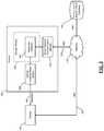
- each entry 200 included in the shared vehicle database 132corresponds to a vehicle ID for the respective shared vehicle. Further, each entry 200 includes access information 204 , a device address 208 , and security information 212 .
- the security information 212may optionally include a PIN code 216 , a link key 220 , and a challenge 224 .
- the access information 204indicates whether the device address 208 is presently granted access to the vehicle that corresponds to the entry 200 , for example, the vehicle 100 of FIG. 1 . As discussed, the access information 204 may be adjusted through the application as further illustrated by application software 300 of FIG. 4 .
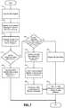
- the authentication module 504is instructed to use the stored PIN code 216 , link key 220 , and/or challenge 224 to authenticate the device 104 .
- the stored security information 212may include a previously paired indicator, instructing the authentication module 504 to bypass authentication and pair the device 104 with the vehicle 100 .
- the compare and upload module 408transmits an indication to the security information module 412 to access the shared vehicle database 132 and use the security information 212 corresponding to the vehicle ID and device address to pair the device 104 with the vehicle 100 . After the security information module 412 is instructed to use the appropriate security information 212 , control ends.
- the override module 500overrides the authentication module 504 , instructing the authentication module 504 to use the security information 212 stored in the shared vehicle database 132 .
- the phrase at least one of A, B, and Cshould be construed to mean a logical (A OR B OR C), using a non-exclusive logical OR, and should not be construed to mean “at least one of A, at least one of B, and at least one of C.”
- the modulemay include one or more interface circuits.
- the interface circuitsmay include wired or wireless interfaces that are connected to a local area network (LAN), the Internet, a wide area network (WAN), or combinations thereof.
- LANlocal area network
- WANwide area network
- the functionality of any given module of the present disclosuremay be distributed among multiple modules that are connected via interface circuits. For example, multiple modules may allow load balancing.
- a server (also known as remote, or cloud) modulemay accomplish some functionality on behalf of a client module.
Landscapes
- Engineering & Computer Science (AREA)
- Computer Networks & Wireless Communication (AREA)
- Signal Processing (AREA)
- Computer Security & Cryptography (AREA)
- Mobile Radio Communication Systems (AREA)
Abstract
Description
Claims (17)
Priority Applications (4)
| Application Number | Priority Date | Filing Date | Title |
|---|---|---|---|
| US16/358,895US10917784B2 (en) | 2018-03-27 | 2019-03-20 | Systems and methods of cloud bonding for vehicles |
| PCT/JP2019/012954WO2019189230A1 (en) | 2018-03-27 | 2019-03-26 | Systems and methods of cloud bonding for vehicles |
| JP2020540819AJP7081675B2 (en) | 2018-03-27 | 2019-03-26 | Cloud bonding system and method for vehicles |
| CN201980021185.5ACN111903148B (en) | 2018-03-27 | 2019-03-26 | Method and system for pairing a device with a vehicle of a plurality of shared vehicles |
Applications Claiming Priority (2)
| Application Number | Priority Date | Filing Date | Title |
|---|---|---|---|
| US201862648786P | 2018-03-27 | 2018-03-27 | |
| US16/358,895US10917784B2 (en) | 2018-03-27 | 2019-03-20 | Systems and methods of cloud bonding for vehicles |
Publications (2)
| Publication Number | Publication Date |
|---|---|
| US20190306703A1 US20190306703A1 (en) | 2019-10-03 |
| US10917784B2true US10917784B2 (en) | 2021-02-09 |
Family
ID=68055818
Family Applications (1)
| Application Number | Title | Priority Date | Filing Date |
|---|---|---|---|
| US16/358,895ActiveUS10917784B2 (en) | 2018-03-27 | 2019-03-20 | Systems and methods of cloud bonding for vehicles |
Country Status (4)
| Country | Link |
|---|---|
| US (1) | US10917784B2 (en) |
| JP (1) | JP7081675B2 (en) |
| CN (1) | CN111903148B (en) |
| WO (1) | WO2019189230A1 (en) |
Cited By (1)
| Publication number | Priority date | Publication date | Assignee | Title |
|---|---|---|---|---|
| US20210258418A1 (en)* | 2018-09-28 | 2021-08-19 | Apple Inc. | Ranging-based reminders |
Families Citing this family (5)
| Publication number | Priority date | Publication date | Assignee | Title |
|---|---|---|---|---|
| US11516025B2 (en)* | 2020-03-19 | 2022-11-29 | Ford Global Technologies, Llc | Advance mobile device and vehicle profile pairing |
| EP4311288A4 (en)* | 2021-03-29 | 2024-05-01 | Huawei Technologies Co., Ltd. | Pairing method and apparatus |
| EP4333381A4 (en)* | 2021-06-25 | 2024-05-29 | Huawei Technologies Co., Ltd. | ORDERING METHOD, SHARING METHOD, DEVICE AND SYSTEM |
| US11745700B2 (en)* | 2021-09-03 | 2023-09-05 | Rivian Ip Holdings, Llc | System and method for efficient management of vehicle power modes |
| CN115001965A (en)* | 2022-06-01 | 2022-09-02 | 上海嘉车信息科技有限公司 | A configuration sharing method and device |
Citations (78)
| Publication number | Priority date | Publication date | Assignee | Title |
|---|---|---|---|---|
| US20040010338A1 (en)* | 2002-07-08 | 2004-01-15 | Honda Giken Kogyo Kabushiki Kaisha | Shared vehicle distribution instruction apparatus and vehicle reservation control apparatus |
| US20040014422A1 (en) | 2002-07-19 | 2004-01-22 | Nokia Corporation | Method and system for handovers using service description data |
| US20050099265A1 (en)* | 2003-11-12 | 2005-05-12 | Dix Peter J. | Central access control system |
| US20050225643A1 (en)* | 2004-03-30 | 2005-10-13 | Raphael Grignani | Context enhanced pictures |
| US20070001805A1 (en)* | 2005-07-01 | 2007-01-04 | Utter Thomas E | Multiple vehicle authentication for entry and starting systems |
| US20090015373A1 (en)* | 2007-07-12 | 2009-01-15 | Kelly Michael P | Methods and systems for secure keyless entry for vehicle fleet management |
| US20090271846A1 (en)* | 2005-09-21 | 2009-10-29 | Thomson Licensing | Method and Device to Suspend the Access to a Service |
| JP2010079469A (en)* | 2008-09-25 | 2010-04-08 | Omron Corp | Group management device and group management method |
| US20100114616A1 (en)* | 2007-03-23 | 2010-05-06 | Renault S.A.S | System for managing a fleet of motor vehicles accessible via a storage key and method for managing the corresponding fleet |
| WO2010090533A2 (en) | 2009-01-07 | 2010-08-12 | Resonance Holdings Limited | Bluetooth authentication system and method |
| US20100280700A1 (en)* | 2007-10-31 | 2010-11-04 | Intrago Corporation | User-distributed shared vehicle system |
| US20110215921A1 (en) | 2009-06-22 | 2011-09-08 | Mourad Ben Ayed | Systems for wireless authentication based on bluetooth proximity |
| US20120045058A1 (en) | 2010-08-20 | 2012-02-23 | Ludger Weghaus | Apparatus and method for authentication for motor vehicles |
| US20130090781A1 (en)* | 2011-10-06 | 2013-04-11 | GM Global Technology Operations LLC | Remotely located database for managing a vehicle fleet |
| US20130214732A1 (en) | 2012-02-22 | 2013-08-22 | Juergen Nowottnick | Wireless power and data apparatus, system and method |
| US20140152091A1 (en) | 2011-07-27 | 2014-06-05 | Marquardt Gmbh | Energy supply circuit for electric components |
| US20140156111A1 (en)* | 2012-12-04 | 2014-06-05 | I.D. Systems, Inc. | Remote vehicle rental systems and methods |
| US20140156110A1 (en)* | 2012-12-04 | 2014-06-05 | I.D. Systems, Inc. | Remote vehicle rental systems and methods |
| US20140188348A1 (en) | 2012-12-27 | 2014-07-03 | GM Global Technology Operations LLC | Method and system for detecting proximity of an end device to a vehicle based on signal strength information received over a bluetooth low energy (ble) advertising channel |
| US20140207629A1 (en)* | 2013-01-22 | 2014-07-24 | The Tb Group, Inc. | System, method, and apparatus for identifying and authenticating the presence of high value assets at remote locations |
| US20140232520A1 (en)* | 2013-02-15 | 2014-08-21 | Kabushiki Kaisha Tokai Rika Denki Seisakusho | Electronic key registration method and electronic key registration system |
| US20140232521A1 (en)* | 2013-02-15 | 2014-08-21 | Kabushiki Kaisha Tokai Rika Denki Seisakusho | Electronic key registration method and electronic key registration system |
| US20140240091A1 (en) | 2013-02-25 | 2014-08-28 | GM Global Technology Operations LLC | Vehicle integration of ble nodes to enable passive entry and passive start features |
| US20140256304A1 (en)* | 2013-03-11 | 2014-09-11 | General Motors Llc | Interface device for providing vehicle services using a vehicle and a mobile communications device |
| US20140274013A1 (en) | 2013-03-14 | 2014-09-18 | Voxx International Corporation | Passive entry cell phone and method and system therefor |
| US20140266580A1 (en)* | 2013-03-15 | 2014-09-18 | Keylessride | Key storage and retrieval |
| EP2800068A2 (en) | 2013-05-01 | 2014-11-05 | Delphi Technologies, Inc. | Relay attack prevention for passive entry passive start (peps) vehicle security systems |
| CN104574593A (en) | 2014-12-24 | 2015-04-29 | 浙江银江研究院有限公司 | Virtual key based on Bluetooth communication as well as anti-theft lock system and application method thereof |
| US20150148989A1 (en) | 2013-11-22 | 2015-05-28 | Qualcomm Incorporated | System and method for implementing a vehicle configuration based on parameters that are specified by a mobile computing device when outside of a vehicle |
| US20150161834A1 (en) | 2013-12-10 | 2015-06-11 | Ford Global Technologies, Llc | User proximity detection for activating vehicle convenience functions |
| US20150161832A1 (en)* | 2013-12-05 | 2015-06-11 | Ford Global Technologies, Llc | Method and Apparatus for Virtual Key Delivery |
| US20150221150A1 (en)* | 2014-02-04 | 2015-08-06 | Ford Global Technologies, Llc | Method and Apparatus for Secure Vehicle System Access from a Remote System |
| US9123244B2 (en) | 2013-03-15 | 2015-09-01 | Denso International America, Inc. | Vehicle tracking of personal devices with response system |
| US20150296441A1 (en)* | 2014-04-15 | 2015-10-15 | General Motors Llc | Managing wireless communication settings in a plurality of vehicles |
| US20150310681A1 (en) | 2014-04-23 | 2015-10-29 | Panasonic Automotive Systems Company Of America, Division Of Panasonic Corporation Of North America | System for assigning a smartphone as a temporary key for a vehicle |
| WO2015177298A1 (en) | 2014-05-21 | 2015-11-26 | Huf Hülsbeck & Fürst Gmbh & Co. Kg | Module unit with interface for a communications device |
| US20150356797A1 (en) | 2014-06-05 | 2015-12-10 | International Business Machines Corporation | Virtual key fob with transferable user data profile |
| BR102014017465A2 (en) | 2014-07-16 | 2016-02-16 | Segtrônica Comércio De Equipamentos E Produtos Ltda | radio frequency electromechanical lock |
| US20160050563A1 (en) | 2014-07-24 | 2016-02-18 | Intel Corporation | Secure wireless charging |
| US20160050699A1 (en)* | 2014-08-15 | 2016-02-18 | International Business Machines Corporation | Pairing of bluetooth devices |
| US20160063786A1 (en) | 2014-08-26 | 2016-03-03 | Hyundai America Technical Center, Inc. | Smartphone enabled passive entry go system |
| US20160087485A1 (en) | 2014-09-24 | 2016-03-24 | Lear Corporation | In-vehicle wireless charging system |
| FR3026212A1 (en) | 2014-09-24 | 2016-03-25 | Valeo Comfort & Driving Assistance | DEVICE FOR MONITORING THE LOCKING / UNLOCKING AND / OR STARTING A VEHICLE |
| US20160150407A1 (en) | 2014-11-26 | 2016-05-26 | Wind River Systems, Inc. | Method And System For Connecting A Mobile Communication Device To An Automobile |
| US20160203661A1 (en)* | 2015-01-14 | 2016-07-14 | GM Global Technology Operations LLC | Virtual keyfob for vehicle sharing |
| WO2016156682A1 (en) | 2015-04-01 | 2016-10-06 | Valeo Comfort And Driving Assistance | Method for loading a virtual key in a user terminal and associated user terminal |
| US20160318481A1 (en)* | 2011-04-22 | 2016-11-03 | Angel A. Penilla | Methods and Systems for Using Cloud Services to Assign e-Keys to Access Vehicles |
| US20170018128A1 (en) | 2015-07-16 | 2017-01-19 | GM Global Technology Operations LLC | Vehicle peps system using directional sensors |
| US20170062938A1 (en) | 2015-08-28 | 2017-03-02 | Zte Corporation | Multiband microline antenna |
| US20170104589A1 (en) | 2015-10-13 | 2017-04-13 | TrustPoint Innovation Technologies, Ltd. | System and Method for Digital Key Sharing for Access Control |
| US20170132533A1 (en)* | 2015-11-09 | 2017-05-11 | Silvercar, Inc. | Vehicle access systems and methods |
| US20170156062A1 (en)* | 2014-07-21 | 2017-06-01 | Wabco Gmbh | Establishing a wireless connection to a vehicle |
| US9688247B1 (en) | 2016-08-03 | 2017-06-27 | Ford Global Technologies, Llc | Method and apparatus for digital temporary vehicle key utilization |
| US20170237849A1 (en)* | 2016-02-16 | 2017-08-17 | Livingston Enterprises Llc | Anti-distracted driver system |
| US9794753B1 (en) | 2016-04-15 | 2017-10-17 | Infinitekey, Inc. | System and method for establishing real-time location |
| WO2017181035A1 (en) | 2016-04-15 | 2017-10-19 | Huf North America Automotive Parts Mfg. Corp. | System and method for communicating with a vehicle |
| US20170309098A1 (en) | 2016-04-26 | 2017-10-26 | Ford Global Technologies, Llc | Systems and methods for phone-as-a-key range extension |
| US20170320215A1 (en)* | 2014-11-26 | 2017-11-09 | Husqvarna Ab | Remote interaction with a robotic vehicle |
| US20170330402A1 (en) | 2014-12-23 | 2017-11-16 | Valeo Comfort And Driving Assistance | Method for secure transmission of a virtual key and method for authentication of a mobile terminal |
| US20170352210A1 (en)* | 2016-06-03 | 2017-12-07 | Volkswagen Aktiengesellschaft | Apparatus, system and method for dynamic identification for vehicle access |
| US20170352215A1 (en)* | 2016-06-03 | 2017-12-07 | Volkswagen Aktiengesellschaft | Apparatus, system and method for vehicle access and function control utilizing a portable device |
| US20170352214A1 (en)* | 2016-06-03 | 2017-12-07 | Volkswagen Aktiengesellschaft | Apparatus, system and method for dynamic identification and key management for vehicle access |
| US20180009416A1 (en)* | 2016-06-03 | 2018-01-11 | Volkswagen Aktiengesellschaft | Apparatus, system and method for vehicle access and function control utilizing a portable device |
| US20180029560A1 (en) | 2016-07-26 | 2018-02-01 | Volkswagen Ag | Method, computer program and apparatus for verifying authorization of a mobile communication device |
| US9894492B1 (en) | 2016-09-22 | 2018-02-13 | Ford Global Technologies, Llc | System and method for determining mobile device location relative to vehicle cabin |
| WO2018040641A1 (en) | 2016-08-31 | 2018-03-08 | 长城汽车股份有限公司 | Mobile terminal, vehicle terminal, and virtual key sharing method and system |
| US20180103414A1 (en) | 2016-10-12 | 2018-04-12 | Denso International America, Inc. | Localization and Passive Entry / Passive Start Systems and Methods for Vehicles |
| US20180099643A1 (en) | 2016-10-12 | 2018-04-12 | Denso International America, Inc. | Passive Entry / Passive Start Systems and Methods for Vehicles |
| US20180126952A1 (en) | 2016-11-10 | 2018-05-10 | GM Global Technology Operations LLC | Virtual key for vehicle servicing |
| US20180154865A1 (en) | 2016-12-07 | 2018-06-07 | Ford Global Technologies, Llc | Authentication of mobile devices for vehicle communication |
| US10002479B2 (en) | 2014-10-01 | 2018-06-19 | Continental Intelligent Transportation Systems, LLC | End to end system for service delivery to and from a vehicle using a dongle |
| US20180269565A1 (en) | 2017-03-14 | 2018-09-20 | R.A. Miller Industries, Inc. | Wideband, low profile, small area, circular polarized uhf antenna |
| US20180284765A1 (en)* | 2016-09-30 | 2018-10-04 | Faraday&Future Inc. | Emergency access to an inactive vehicle |
| US20180338237A1 (en)* | 2017-05-17 | 2018-11-22 | Hand Held Products, Inc. | Systems and methods for improving alert messaging using device to device communication |
| US20190092280A1 (en)* | 2017-09-28 | 2019-03-28 | General Motors Llc | Vehicle sharing accessory module and system |
| US20190205797A1 (en)* | 2017-12-28 | 2019-07-04 | Toyota Jidosha Kabushiki Kaisha | Carsharing system and carsharing method |
| US20200114874A1 (en)* | 2017-10-31 | 2020-04-16 | Komatsu Ltd. | Communication monitoring device, communication monitoring system, and communication monitoring method |
| US20200133268A1 (en)* | 2018-10-30 | 2020-04-30 | Here Global B.V. | Virtual valet |
Family Cites Families (10)
| Publication number | Priority date | Publication date | Assignee | Title |
|---|---|---|---|---|
| US20090270036A1 (en)* | 2008-04-29 | 2009-10-29 | Microsoft Corporation | Wireless Pairing Ceremony |
| EP2568421A1 (en)* | 2011-09-07 | 2013-03-13 | Amadeus | Method and system for accessing places |
| US20140133656A1 (en)* | 2012-02-22 | 2014-05-15 | Qualcomm Incorporated | Preserving Security by Synchronizing a Nonce or Counter Between Systems |
| KR20150009869A (en)* | 2013-07-17 | 2015-01-27 | 주식회사 포스코 | Twin roll strip caster |
| CN104627122B (en)* | 2013-11-11 | 2017-06-06 | 比亚迪股份有限公司 | Method and method, the system of control vehicle that digital key is bound with vehicle |
| FR3015820B1 (en)* | 2013-12-20 | 2017-06-09 | Valeo Securite Habitacle | MOBILE TELEPHONE FIT TO AUTOMATICALLY APPARE WITH A MOTOR VEHICLE AND AUTOMATIC PAIRING METHOD |
| US9917843B2 (en)* | 2015-01-07 | 2018-03-13 | Kii, Inc. | Secure data management techniques |
| CN106533476B (en)* | 2015-09-14 | 2019-02-12 | 广州汽车集团股份有限公司 | Method and system for binding vehicle and vehicle terminal |
| CN113194207B (en)* | 2016-04-18 | 2023-05-05 | 阿菲尼帝有限公司 | Techniques for benchmarking pairing strategies in a contact center system |
| CN106658382A (en)* | 2017-01-03 | 2017-05-10 | 湖北弘方科技股份有限公司 | Intelligent control system based on BLE |
- 2019
- 2019-03-20USUS16/358,895patent/US10917784B2/enactiveActive
- 2019-03-26CNCN201980021185.5Apatent/CN111903148B/enactiveActive
- 2019-03-26JPJP2020540819Apatent/JP7081675B2/enactiveActive
- 2019-03-26WOPCT/JP2019/012954patent/WO2019189230A1/ennot_activeCeased
Patent Citations (85)
| Publication number | Priority date | Publication date | Assignee | Title |
|---|---|---|---|---|
| US20040010338A1 (en)* | 2002-07-08 | 2004-01-15 | Honda Giken Kogyo Kabushiki Kaisha | Shared vehicle distribution instruction apparatus and vehicle reservation control apparatus |
| US20040014422A1 (en) | 2002-07-19 | 2004-01-22 | Nokia Corporation | Method and system for handovers using service description data |
| US20050099265A1 (en)* | 2003-11-12 | 2005-05-12 | Dix Peter J. | Central access control system |
| US20050225643A1 (en)* | 2004-03-30 | 2005-10-13 | Raphael Grignani | Context enhanced pictures |
| US20070001805A1 (en)* | 2005-07-01 | 2007-01-04 | Utter Thomas E | Multiple vehicle authentication for entry and starting systems |
| US20090271846A1 (en)* | 2005-09-21 | 2009-10-29 | Thomson Licensing | Method and Device to Suspend the Access to a Service |
| US20100114616A1 (en)* | 2007-03-23 | 2010-05-06 | Renault S.A.S | System for managing a fleet of motor vehicles accessible via a storage key and method for managing the corresponding fleet |
| US20090015373A1 (en)* | 2007-07-12 | 2009-01-15 | Kelly Michael P | Methods and systems for secure keyless entry for vehicle fleet management |
| US20100280700A1 (en)* | 2007-10-31 | 2010-11-04 | Intrago Corporation | User-distributed shared vehicle system |
| JP2010079469A (en)* | 2008-09-25 | 2010-04-08 | Omron Corp | Group management device and group management method |
| WO2010090533A2 (en) | 2009-01-07 | 2010-08-12 | Resonance Holdings Limited | Bluetooth authentication system and method |
| US20120108208A1 (en) | 2009-01-07 | 2012-05-03 | Resonance Holdings Limited | Bluetooth authentication system and method |
| US20110215921A1 (en) | 2009-06-22 | 2011-09-08 | Mourad Ben Ayed | Systems for wireless authentication based on bluetooth proximity |
| US20120045058A1 (en) | 2010-08-20 | 2012-02-23 | Ludger Weghaus | Apparatus and method for authentication for motor vehicles |
| US20160318481A1 (en)* | 2011-04-22 | 2016-11-03 | Angel A. Penilla | Methods and Systems for Using Cloud Services to Assign e-Keys to Access Vehicles |
| US20140152091A1 (en) | 2011-07-27 | 2014-06-05 | Marquardt Gmbh | Energy supply circuit for electric components |
| US20130090781A1 (en)* | 2011-10-06 | 2013-04-11 | GM Global Technology Operations LLC | Remotely located database for managing a vehicle fleet |
| US20130214732A1 (en) | 2012-02-22 | 2013-08-22 | Juergen Nowottnick | Wireless power and data apparatus, system and method |
| US20140156111A1 (en)* | 2012-12-04 | 2014-06-05 | I.D. Systems, Inc. | Remote vehicle rental systems and methods |
| US20140156110A1 (en)* | 2012-12-04 | 2014-06-05 | I.D. Systems, Inc. | Remote vehicle rental systems and methods |
| US20140188348A1 (en) | 2012-12-27 | 2014-07-03 | GM Global Technology Operations LLC | Method and system for detecting proximity of an end device to a vehicle based on signal strength information received over a bluetooth low energy (ble) advertising channel |
| US20140207629A1 (en)* | 2013-01-22 | 2014-07-24 | The Tb Group, Inc. | System, method, and apparatus for identifying and authenticating the presence of high value assets at remote locations |
| US20140232520A1 (en)* | 2013-02-15 | 2014-08-21 | Kabushiki Kaisha Tokai Rika Denki Seisakusho | Electronic key registration method and electronic key registration system |
| US20140232521A1 (en)* | 2013-02-15 | 2014-08-21 | Kabushiki Kaisha Tokai Rika Denki Seisakusho | Electronic key registration method and electronic key registration system |
| US20140240091A1 (en) | 2013-02-25 | 2014-08-28 | GM Global Technology Operations LLC | Vehicle integration of ble nodes to enable passive entry and passive start features |
| US20140256304A1 (en)* | 2013-03-11 | 2014-09-11 | General Motors Llc | Interface device for providing vehicle services using a vehicle and a mobile communications device |
| US20140274013A1 (en) | 2013-03-14 | 2014-09-18 | Voxx International Corporation | Passive entry cell phone and method and system therefor |
| US9123244B2 (en) | 2013-03-15 | 2015-09-01 | Denso International America, Inc. | Vehicle tracking of personal devices with response system |
| US20140266580A1 (en)* | 2013-03-15 | 2014-09-18 | Keylessride | Key storage and retrieval |
| EP2800068A2 (en) | 2013-05-01 | 2014-11-05 | Delphi Technologies, Inc. | Relay attack prevention for passive entry passive start (peps) vehicle security systems |
| US20140330449A1 (en) | 2013-05-01 | 2014-11-06 | Delphi Technologies, Inc | Relay attack prevention for passive entry passive start (peps) vehicle security systems |
| US8930045B2 (en) | 2013-05-01 | 2015-01-06 | Delphi Technologies, Inc. | Relay attack prevention for passive entry passive start (PEPS) vehicle security systems |
| US20150148989A1 (en) | 2013-11-22 | 2015-05-28 | Qualcomm Incorporated | System and method for implementing a vehicle configuration based on parameters that are specified by a mobile computing device when outside of a vehicle |
| US20150161832A1 (en)* | 2013-12-05 | 2015-06-11 | Ford Global Technologies, Llc | Method and Apparatus for Virtual Key Delivery |
| US20150161834A1 (en) | 2013-12-10 | 2015-06-11 | Ford Global Technologies, Llc | User proximity detection for activating vehicle convenience functions |
| US20150221150A1 (en)* | 2014-02-04 | 2015-08-06 | Ford Global Technologies, Llc | Method and Apparatus for Secure Vehicle System Access from a Remote System |
| US20150296441A1 (en)* | 2014-04-15 | 2015-10-15 | General Motors Llc | Managing wireless communication settings in a plurality of vehicles |
| US20150310681A1 (en) | 2014-04-23 | 2015-10-29 | Panasonic Automotive Systems Company Of America, Division Of Panasonic Corporation Of North America | System for assigning a smartphone as a temporary key for a vehicle |
| WO2015177298A1 (en) | 2014-05-21 | 2015-11-26 | Huf Hülsbeck & Fürst Gmbh & Co. Kg | Module unit with interface for a communications device |
| US20150356797A1 (en) | 2014-06-05 | 2015-12-10 | International Business Machines Corporation | Virtual key fob with transferable user data profile |
| BR102014017465A2 (en) | 2014-07-16 | 2016-02-16 | Segtrônica Comércio De Equipamentos E Produtos Ltda | radio frequency electromechanical lock |
| US20170156062A1 (en)* | 2014-07-21 | 2017-06-01 | Wabco Gmbh | Establishing a wireless connection to a vehicle |
| US20160050563A1 (en) | 2014-07-24 | 2016-02-18 | Intel Corporation | Secure wireless charging |
| US20160050699A1 (en)* | 2014-08-15 | 2016-02-18 | International Business Machines Corporation | Pairing of bluetooth devices |
| US20160063786A1 (en) | 2014-08-26 | 2016-03-03 | Hyundai America Technical Center, Inc. | Smartphone enabled passive entry go system |
| US20160087485A1 (en) | 2014-09-24 | 2016-03-24 | Lear Corporation | In-vehicle wireless charging system |
| FR3026212A1 (en) | 2014-09-24 | 2016-03-25 | Valeo Comfort & Driving Assistance | DEVICE FOR MONITORING THE LOCKING / UNLOCKING AND / OR STARTING A VEHICLE |
| US20170236351A1 (en) | 2014-09-24 | 2017-08-17 | Valeo Comfort And Driving Assistance | Device for controlling locking/unlocking and/or starting of a vehicle |
| US10002479B2 (en) | 2014-10-01 | 2018-06-19 | Continental Intelligent Transportation Systems, LLC | End to end system for service delivery to and from a vehicle using a dongle |
| US20160150407A1 (en) | 2014-11-26 | 2016-05-26 | Wind River Systems, Inc. | Method And System For Connecting A Mobile Communication Device To An Automobile |
| US20170320215A1 (en)* | 2014-11-26 | 2017-11-09 | Husqvarna Ab | Remote interaction with a robotic vehicle |
| US20170330402A1 (en) | 2014-12-23 | 2017-11-16 | Valeo Comfort And Driving Assistance | Method for secure transmission of a virtual key and method for authentication of a mobile terminal |
| CN104574593A (en) | 2014-12-24 | 2015-04-29 | 浙江银江研究院有限公司 | Virtual key based on Bluetooth communication as well as anti-theft lock system and application method thereof |
| US20160203661A1 (en)* | 2015-01-14 | 2016-07-14 | GM Global Technology Operations LLC | Virtual keyfob for vehicle sharing |
| WO2016156682A1 (en) | 2015-04-01 | 2016-10-06 | Valeo Comfort And Driving Assistance | Method for loading a virtual key in a user terminal and associated user terminal |
| US20170018128A1 (en) | 2015-07-16 | 2017-01-19 | GM Global Technology Operations LLC | Vehicle peps system using directional sensors |
| US20170062938A1 (en) | 2015-08-28 | 2017-03-02 | Zte Corporation | Multiband microline antenna |
| US20170104589A1 (en) | 2015-10-13 | 2017-04-13 | TrustPoint Innovation Technologies, Ltd. | System and Method for Digital Key Sharing for Access Control |
| US20170132533A1 (en)* | 2015-11-09 | 2017-05-11 | Silvercar, Inc. | Vehicle access systems and methods |
| US20170237849A1 (en)* | 2016-02-16 | 2017-08-17 | Livingston Enterprises Llc | Anti-distracted driver system |
| WO2017181050A1 (en) | 2016-04-15 | 2017-10-19 | Infinitekey, Inc. | System and method for establishing real-time location |
| US20170303080A1 (en) | 2016-04-15 | 2017-10-19 | Infinitekey, Inc. | System and method for establishing real-time location |
| US20170303090A1 (en) | 2016-04-15 | 2017-10-19 | Infinitekey, Inc. | System and method for establishing real-time location |
| WO2017181035A1 (en) | 2016-04-15 | 2017-10-19 | Huf North America Automotive Parts Mfg. Corp. | System and method for communicating with a vehicle |
| US9794753B1 (en) | 2016-04-15 | 2017-10-17 | Infinitekey, Inc. | System and method for establishing real-time location |
| US20170309098A1 (en) | 2016-04-26 | 2017-10-26 | Ford Global Technologies, Llc | Systems and methods for phone-as-a-key range extension |
| US20170352215A1 (en)* | 2016-06-03 | 2017-12-07 | Volkswagen Aktiengesellschaft | Apparatus, system and method for vehicle access and function control utilizing a portable device |
| US20170352214A1 (en)* | 2016-06-03 | 2017-12-07 | Volkswagen Aktiengesellschaft | Apparatus, system and method for dynamic identification and key management for vehicle access |
| US20180009416A1 (en)* | 2016-06-03 | 2018-01-11 | Volkswagen Aktiengesellschaft | Apparatus, system and method for vehicle access and function control utilizing a portable device |
| US20170352210A1 (en)* | 2016-06-03 | 2017-12-07 | Volkswagen Aktiengesellschaft | Apparatus, system and method for dynamic identification for vehicle access |
| US20180029560A1 (en) | 2016-07-26 | 2018-02-01 | Volkswagen Ag | Method, computer program and apparatus for verifying authorization of a mobile communication device |
| US9688247B1 (en) | 2016-08-03 | 2017-06-27 | Ford Global Technologies, Llc | Method and apparatus for digital temporary vehicle key utilization |
| WO2018040641A1 (en) | 2016-08-31 | 2018-03-08 | 长城汽车股份有限公司 | Mobile terminal, vehicle terminal, and virtual key sharing method and system |
| US9894492B1 (en) | 2016-09-22 | 2018-02-13 | Ford Global Technologies, Llc | System and method for determining mobile device location relative to vehicle cabin |
| US20180284765A1 (en)* | 2016-09-30 | 2018-10-04 | Faraday&Future Inc. | Emergency access to an inactive vehicle |
| US20180099643A1 (en) | 2016-10-12 | 2018-04-12 | Denso International America, Inc. | Passive Entry / Passive Start Systems and Methods for Vehicles |
| US20180103414A1 (en) | 2016-10-12 | 2018-04-12 | Denso International America, Inc. | Localization and Passive Entry / Passive Start Systems and Methods for Vehicles |
| US20180126952A1 (en) | 2016-11-10 | 2018-05-10 | GM Global Technology Operations LLC | Virtual key for vehicle servicing |
| US20180154865A1 (en) | 2016-12-07 | 2018-06-07 | Ford Global Technologies, Llc | Authentication of mobile devices for vehicle communication |
| US20180269565A1 (en) | 2017-03-14 | 2018-09-20 | R.A. Miller Industries, Inc. | Wideband, low profile, small area, circular polarized uhf antenna |
| US20180338237A1 (en)* | 2017-05-17 | 2018-11-22 | Hand Held Products, Inc. | Systems and methods for improving alert messaging using device to device communication |
| US20190092280A1 (en)* | 2017-09-28 | 2019-03-28 | General Motors Llc | Vehicle sharing accessory module and system |
| US20200114874A1 (en)* | 2017-10-31 | 2020-04-16 | Komatsu Ltd. | Communication monitoring device, communication monitoring system, and communication monitoring method |
| US20190205797A1 (en)* | 2017-12-28 | 2019-07-04 | Toyota Jidosha Kabushiki Kaisha | Carsharing system and carsharing method |
| US20200133268A1 (en)* | 2018-10-30 | 2020-04-30 | Here Global B.V. | Virtual valet |
Cited By (3)
| Publication number | Priority date | Publication date | Assignee | Title |
|---|---|---|---|---|
| US20210258418A1 (en)* | 2018-09-28 | 2021-08-19 | Apple Inc. | Ranging-based reminders |
| US11671530B2 (en)* | 2018-09-28 | 2023-06-06 | Apple Inc. | Ranging-based reminders |
| US12177378B2 (en) | 2018-09-28 | 2024-12-24 | Apple Inc. | Ranging between mobile devices |
Also Published As
| Publication number | Publication date |
|---|---|
| JP7081675B2 (en) | 2022-06-07 |
| US20190306703A1 (en) | 2019-10-03 |
| JP2021511604A (en) | 2021-05-06 |
| CN111903148B (en) | 2023-10-13 |
| WO2019189230A1 (en) | 2019-10-03 |
| CN111903148A (en) | 2020-11-06 |
Similar Documents
| Publication | Publication Date | Title |
|---|---|---|
| US10917784B2 (en) | Systems and methods of cloud bonding for vehicles | |
| US10854029B2 (en) | Decentralized virtual trustless database for access control | |
| US11548517B2 (en) | Activating vehicle functions based on vehicle occupant location | |
| US11641678B2 (en) | Secure wireless networks for vehicle assigning authority | |
| US8498771B2 (en) | Wireless vehicle servicing | |
| US11097689B2 (en) | Passive entry and passive start system and method using temporary keys | |
| US11366885B2 (en) | Vehicle security system and vehicle security method | |
| WO2019189261A1 (en) | Statistics based systems and methods for activating vehicle functions | |
| US20180293823A1 (en) | System and Method for Access Control | |
| US20170353451A1 (en) | Method and apparatus for issuing a credential for an incident area network | |
| US20170308365A1 (en) | Facilitating mobile device application installation using a vehicle | |
| CN111989905B (en) | System and method for communication bus security in a vehicle | |
| CN109905356A (en) | Equipment will be tethered at based on available credit or data remaining sum to guide to the system and method for vehicle-mounted storage login page | |
| US10967836B2 (en) | Phone as a key vehicle access based on time policies, license information and validation and accuracy of a vehicle real time clock | |
| US10706140B2 (en) | Vehicle computer update authentication | |
| US20200293304A1 (en) | Vehicle computer update authentication | |
| US11495073B2 (en) | Decentralized virtual trustless database for access control | |
| JP2020201857A (en) | Authentication system and authentication method | |
| CN114584954B (en) | Vehicle-mounted association method and device | |
| JP7690225B2 (en) | How to set up the door lock interlocking system using Door Lock Administrator privileges | |
| KR102706926B1 (en) | Decentralized identifier management method and decentralized identifier management apparatus for vehicle system | |
| US11654863B2 (en) | Vehicle control and identification systems and methods | |
| CN113010893A (en) | Software management method, device and system |
Legal Events
| Date | Code | Title | Description |
|---|---|---|---|
| FEPP | Fee payment procedure | Free format text:ENTITY STATUS SET TO UNDISCOUNTED (ORIGINAL EVENT CODE: BIG.); ENTITY STATUS OF PATENT OWNER: LARGE ENTITY | |
| AS | Assignment | Owner name:DENSO INTERNATIONAL AMERICA, INC., MICHIGAN Free format text:ASSIGNMENT OF ASSIGNORS INTEREST;ASSIGNOR:GOLSCH, KYLE;REEL/FRAME:048663/0662 Effective date:20190320 | |
| AS | Assignment | Owner name:DENSO CORPORATION, JAPAN Free format text:ASSIGNMENT OF ASSIGNORS INTEREST;ASSIGNOR:DENSO INTERNATIONAL AMERICA, INC.;REEL/FRAME:048701/0786 Effective date:20190322 Owner name:DENSO INTERNATIONAL AMERICA, INC., MICHIGAN Free format text:ASSIGNMENT OF ASSIGNORS INTEREST;ASSIGNOR:DENSO INTERNATIONAL AMERICA, INC.;REEL/FRAME:048701/0786 Effective date:20190322 | |
| STPP | Information on status: patent application and granting procedure in general | Free format text:NON FINAL ACTION MAILED | |
| STPP | Information on status: patent application and granting procedure in general | Free format text:PUBLICATIONS -- ISSUE FEE PAYMENT VERIFIED | |
| STCF | Information on status: patent grant | Free format text:PATENTED CASE | |
| MAFP | Maintenance fee payment | Free format text:PAYMENT OF MAINTENANCE FEE, 4TH YEAR, LARGE ENTITY (ORIGINAL EVENT CODE: M1551); ENTITY STATUS OF PATENT OWNER: LARGE ENTITY Year of fee payment:4 |