US10917616B2 - Imaging system and imaging device - Google Patents
Imaging system and imaging deviceDownload PDFInfo
- Publication number
- US10917616B2 US10917616B2US16/414,197US201916414197AUS10917616B2US 10917616 B2US10917616 B2US 10917616B2US 201916414197 AUS201916414197 AUS 201916414197AUS 10917616 B2US10917616 B2US 10917616B2
- Authority
- US
- United States
- Prior art keywords
- image capturing
- capturing device
- image
- images
- image data
- Prior art date
- Legal status (The legal status is an assumption and is not a legal conclusion. Google has not performed a legal analysis and makes no representation as to the accuracy of the status listed.)
- Active
Links
- 238000003384imaging methodMethods0.000titleclaimsdescription6
- 230000006854communicationEffects0.000claimsabstractdescription75
- 238000004891communicationMethods0.000claimsabstractdescription75
- 238000003860storageMethods0.000claimsdescription36
- 238000012360testing methodMethods0.000claimsdescription22
- 238000000034methodMethods0.000description13
- 235000013305foodNutrition0.000description12
- 230000008569processEffects0.000description12
- 230000003287optical effectEffects0.000description11
- 238000005057refrigerationMethods0.000description10
- 230000007175bidirectional communicationEffects0.000description8
- 239000012774insulation materialSubstances0.000description5
- JOYRKODLDBILNP-UHFFFAOYSA-NEthyl urethaneChemical compoundCCOC(N)=OJOYRKODLDBILNP-UHFFFAOYSA-N0.000description4
- 238000001816coolingMethods0.000description3
- 238000009434installationMethods0.000description3
- 230000007246mechanismEffects0.000description3
- 230000000737periodic effectEffects0.000description3
- 239000000758substrateSubstances0.000description3
- 238000001514detection methodMethods0.000description2
- 239000011888foilSubstances0.000description2
- 239000011521glassSubstances0.000description2
- 239000000463materialSubstances0.000description2
- 229910052751metalInorganic materials0.000description2
- 239000002184metalSubstances0.000description2
- 238000012545processingMethods0.000description2
- 230000004044responseEffects0.000description2
- 229910052782aluminiumInorganic materials0.000description1
- XAGFODPZIPBFFR-UHFFFAOYSA-NaluminiumChemical compound[Al]XAGFODPZIPBFFR-UHFFFAOYSA-N0.000description1
- 230000008901benefitEffects0.000description1
- 230000008859changeEffects0.000description1
- 239000011162core materialSubstances0.000description1
- 230000003247decreasing effectEffects0.000description1
- 238000003745diagnosisMethods0.000description1
- 230000000694effectsEffects0.000description1
- 230000005611electricityEffects0.000description1
- 230000006870functionEffects0.000description1
- 239000003365glass fiberSubstances0.000description1
- 238000010348incorporationMethods0.000description1
- 238000010030laminatingMethods0.000description1
- 230000014759maintenance of locationEffects0.000description1
- 239000007769metal materialSubstances0.000description1
- 238000012986modificationMethods0.000description1
- 230000004048modificationEffects0.000description1
- 239000012466permeateSubstances0.000description1
- 229920005989resinPolymers0.000description1
- 239000011347resinSubstances0.000description1
- 238000006467substitution reactionMethods0.000description1
- 229920003002synthetic resinPolymers0.000description1
- 239000000057synthetic resinSubstances0.000description1
- 235000013311vegetablesNutrition0.000description1
- 238000012800visualizationMethods0.000description1
Images


Classifications
- F—MECHANICAL ENGINEERING; LIGHTING; HEATING; WEAPONS; BLASTING
- F25—REFRIGERATION OR COOLING; COMBINED HEATING AND REFRIGERATION SYSTEMS; HEAT PUMP SYSTEMS; MANUFACTURE OR STORAGE OF ICE; LIQUEFACTION SOLIDIFICATION OF GASES
- F25D—REFRIGERATORS; COLD ROOMS; ICE-BOXES; COOLING OR FREEZING APPARATUS NOT OTHERWISE PROVIDED FOR
- F25D29/00—Arrangement or mounting of control or safety devices
- H—ELECTRICITY
- H04—ELECTRIC COMMUNICATION TECHNIQUE
- H04N—PICTORIAL COMMUNICATION, e.g. TELEVISION
- H04N7/00—Television systems
- H04N7/18—Closed-circuit television [CCTV] systems, i.e. systems in which the video signal is not broadcast
- H04N7/183—Closed-circuit television [CCTV] systems, i.e. systems in which the video signal is not broadcast for receiving images from a single remote source
- F—MECHANICAL ENGINEERING; LIGHTING; HEATING; WEAPONS; BLASTING
- F25—REFRIGERATION OR COOLING; COMBINED HEATING AND REFRIGERATION SYSTEMS; HEAT PUMP SYSTEMS; MANUFACTURE OR STORAGE OF ICE; LIQUEFACTION SOLIDIFICATION OF GASES
- F25D—REFRIGERATORS; COLD ROOMS; ICE-BOXES; COOLING OR FREEZING APPARATUS NOT OTHERWISE PROVIDED FOR
- F25D27/00—Lighting arrangements
- F25D27/005—Lighting arrangements combined with control means
- F—MECHANICAL ENGINEERING; LIGHTING; HEATING; WEAPONS; BLASTING
- F25—REFRIGERATION OR COOLING; COMBINED HEATING AND REFRIGERATION SYSTEMS; HEAT PUMP SYSTEMS; MANUFACTURE OR STORAGE OF ICE; LIQUEFACTION SOLIDIFICATION OF GASES
- F25D—REFRIGERATORS; COLD ROOMS; ICE-BOXES; COOLING OR FREEZING APPARATUS NOT OTHERWISE PROVIDED FOR
- F25D29/00—Arrangement or mounting of control or safety devices
- F25D29/005—Mounting of control devices
- H—ELECTRICITY
- H04—ELECTRIC COMMUNICATION TECHNIQUE
- H04N—PICTORIAL COMMUNICATION, e.g. TELEVISION
- H04N23/00—Cameras or camera modules comprising electronic image sensors; Control thereof
- H04N23/57—Mechanical or electrical details of cameras or camera modules specially adapted for being embedded in other devices
- H—ELECTRICITY
- H04—ELECTRIC COMMUNICATION TECHNIQUE
- H04N—PICTORIAL COMMUNICATION, e.g. TELEVISION
- H04N23/00—Cameras or camera modules comprising electronic image sensors; Control thereof
- H04N23/60—Control of cameras or camera modules
- H04N23/63—Control of cameras or camera modules by using electronic viewfinders
- H04N23/633—Control of cameras or camera modules by using electronic viewfinders for displaying additional information relating to control or operation of the camera
- H—ELECTRICITY
- H04—ELECTRIC COMMUNICATION TECHNIQUE
- H04N—PICTORIAL COMMUNICATION, e.g. TELEVISION
- H04N23/00—Cameras or camera modules comprising electronic image sensors; Control thereof
- H04N23/60—Control of cameras or camera modules
- H04N23/65—Control of camera operation in relation to power supply
- H04N23/651—Control of camera operation in relation to power supply for reducing power consumption by affecting camera operations, e.g. sleep mode, hibernation mode or power off of selective parts of the camera
- H—ELECTRICITY
- H04—ELECTRIC COMMUNICATION TECHNIQUE
- H04N—PICTORIAL COMMUNICATION, e.g. TELEVISION
- H04N23/00—Cameras or camera modules comprising electronic image sensors; Control thereof
- H04N23/60—Control of cameras or camera modules
- H04N23/66—Remote control of cameras or camera parts, e.g. by remote control devices
- H04N23/661—Transmitting camera control signals through networks, e.g. control via the Internet
- H—ELECTRICITY
- H04—ELECTRIC COMMUNICATION TECHNIQUE
- H04N—PICTORIAL COMMUNICATION, e.g. TELEVISION
- H04N23/00—Cameras or camera modules comprising electronic image sensors; Control thereof
- H04N23/60—Control of cameras or camera modules
- H04N23/667—Camera operation mode switching, e.g. between still and video, sport and normal or high- and low-resolution modes
- H—ELECTRICITY
- H04—ELECTRIC COMMUNICATION TECHNIQUE
- H04N—PICTORIAL COMMUNICATION, e.g. TELEVISION
- H04N23/00—Cameras or camera modules comprising electronic image sensors; Control thereof
- H04N23/70—Circuitry for compensating brightness variation in the scene
- H04N23/71—Circuitry for evaluating the brightness variation
- H04N5/2257—
- H04N5/23206—
- H04N5/23241—
- H04N5/232411—
- H04N5/23245—
- H04N5/232939—
- H04N5/2351—
Definitions
- Embodiments disclosed hereinrelate to an image capturing system and an image capturing device.
- a refrigerator system using a camerahas been proposed to obtain information of food stored inside the refrigerator.
- the above described camerarequires user instructions every time an image of the fridge interior is to be captured in order to obtain information of the fridge interior. That is, a camera provided with an image capturing portion requires troublesome operations such as acquiring image data by user operation of the operating portion.
- FIG. 1is a schematic view of an image capturing system of one embodiment.
- FIG. 2Ais a front view illustrating the external look of an image capturing device and FIG. 2B is a vertical cross-sectional view illustrating an internal structure of the image capturing device.
- FIG. 3is schematically illustrates an electric configuration of the image capturing device and the in-fridge image capturing system.
- FIG. 4is a flowchart of a main process.
- FIG. 5is a flowchart of a first image capturing process.
- FIG. 6is a flowchart of a second image capturing process.
- an image capturing systemis configured so that a device for capturing images is communicable with an external device through a communication unit.
- the image capturing systemis provided with an operating unit configured to make settings pertaining to image capturing, an image capturing device serving as the device for capturing images and being configured to produce image data by periodically capturing images based on the settings made to the operating unit and a display unit configured to produce a display output based on the image data.
- an image capturing deviceis used in an image capturing system provided with a display unit configured to produce a display output based on image data and an operating unit configured to make settings pertaining to image capturing.
- the image capturing deviceis provided with an image capturing portion configured to produce image data by periodically capturing images based on the settings made to the operating unit; and a communication unit configured to communicate with an external device.
- the image datais transmittable to the external device through the communication portion.
- Embodiments disclosed hereinprovide an image capturing system and an image capturing device with improved usability to be suitable for practical use.
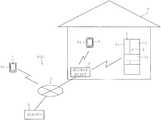
- an image capturing system 100 of the present embodimentis configured by a refrigerator 1 being one example of a home appliance, an image capturing device 2 for capturing an in-room image, an access point 3 , and an external device such as a mobile terminal 4 , etc.
- the access point 3is connected to an external network 5 and is configured to communicate with the image capturing device 2 , etc.
- the access point 3communicably interconnects the mobile terminal 4 and a server 6 , etc. located in remote locations with the image capturing device 2 side or the refrigerator 1 side by way of the external network 5 .
- a Bluetooth (registered trademark) wireless communicationis exchanged between the image capturing device 2 and the access point 3 ; between the access point 3 and the mobile terminal 4 ; and between the refrigerator 1 and the access point 3 .
- the mobile terminal 4is provided with a display screen 4 a configured to display image data captured by the image capturing device 2 .
- the mobile terminal 4serves as a communication terminal and examples of a communication terminal envisaged in the present embodiment include the so-called smart phone (highly functional mobile phone). Examples of the communication terminals include, apart from the mobile terminal 4 discussed herein, a tablet PC.
- the mobile terminal 4is located inside a residence 7 , the mobile terminal 4 is communicably connected to the access point 3 by a close-range wireless communication.
- the mobile terminal 4is located outside the residence 7 , the mobile terminal 4 is communicably connected to the access point 3 by a wide-range wireless communication by way of external network 5 .
- the mobile terminal 4is further capable of connecting to the access point 3 by way of the external network 5 through wide-range communication even when located inside of the residence 7 .
- the mobile terminal 4 located inside the residence 7is further capable of communicating directly with the camera device side 2 or the refrigerator 1 side without the intervention of the access point 3
- the server 6is configured by a computer system known in the art.
- the server 6is provided with a storing unit configured to store image data captured by the image capturing device 2 .
- the storing unit of the server 6includes nonvolatile memory such as a ROM, volatile memory such as a RAM, and electrically rewritable nonvolatile memory such as an EEPROM.
- the storing unit of the server 6stores information (such as an IP address) for accessing the image capturing device 2 .
- the mobile terminal 4 and the server 6 , etc.are provided with a display unit (only the display screen 4 a of the mobile terminal 4 is illustrated in FIG. 1 ) configured to produce a display output based on the image data.
- the mobile terminal 4 and the server 6 , etc.are examples of an external device.
- the display unitmay be provided at the image capturing device 2 .
- the network of home appliancesprovides a user friendly, convenient, and an easy to use system by offering functionalities such as those exemplified above.
- the image capturing device 2 of the present embodimentis installed to the refrigerator 1 by the user so that images of the status inside the refrigerator 1 (that is, the status of items stored in the fridge) can be captured.
- Various information pertaining to each of the home appliances and image data captured by the image capturing device 2 , etc.is stored in the server 6 or transmitted to the mobile terminal 4 . It is thus, possible to view such information through the mobile terminal 4 , etc. over the external network 5 any time even from remote locations.
- the refrigerator 1being one example of a storage, is provided with a refrigeration chamber in its upper portion.
- the refrigeration chamberis opened/closed by left and right doors 1 a and 1 b taking a double door configuration.
- the image capturing device 2is disposed in the rear surface side (at the door pocket not illustrated in the inner side) of the right side door 1 b having the greater lateral dimension among the doors 1 a and 1 b (see the double-dot chain line illustrated in FIG. 1 ).
- the image capturing device 2is to be further installed in a position allowing easy look of the fridge interior such as at the rear surface side of a drawer-type door 1 c in the vegetable chamber located below the refrigeration chamber.
- the front surface of the doors 1 a to 1 c of the refrigerator 1are covered by a glass plate formed of an insulative glass allowing permeation of radio waves.
- the interior of the doors 1 a to 1 care packed with a fill material such as urethane serving as a thermal insulation material.
- the rear surfaces of doors 1 a to 1 care configured by a nonmetallic resin plate.
- a vacuum thermal insulation materialmay be used instead of urethane or with urethane to serve as a thermal insulation material of the refrigerator 1 .
- the vacuum insulation materialis formed into a thin rectangular plate for example by wrapping a core material with glass fiber, etc. with a film formed by adhering (laminating) a metal foil (aluminum foil for example) on a film made of synthetic resin for example.
- the image capturing device 2has a body 10 serving as an outer shell shaped like a cuboid as illustrated in FIG. 2A .
- the image capturing device 2comprises a camera provided with a lighting unit allowing images to be captured in a dark room such as the interior of the refrigerator 1 .
- An image capturing lens 12 , an image capturing lighting 13 , and a light sensor 14 aare provided on the body 10 in an exposed manner.
- a descriptionis given hereinafter with an assumption that the exposed side of the body 10 where the lens 12 , etc. are exposed (the right side in FIG. 2B ) is the main surface 10 a of the image capturing device 2 and the opposite side is the rear surface.
- the lens 12 and the light 13may be hidden under a cover, etc. instead of being exposed outside the body 10 .
- a control substrate 15As illustrated in FIG. 2B , a control substrate 15 , a battery 16 , and a communication module 17 are stored inside the body 10 .
- a couple of lights 13comprising an LED and the lens 12 are implemented on the control substrate 15 .
- the couple of lights 13are disposed in two opposing sides of the lens 12 .
- the direction of irradiation of the lights 13is oriented in the direction of image capturing of the image capturing device 2 so that the interior of the dark room is illuminated by the light irradiated when image is captured.
- the lights 13 and the optical sensor 14 aserve as the lighting unit.
- An image capturing portion 11illustrated in FIG. 3 ), configured by elements such as CCD and CMOS known in the art, and image capturing side controller 18 are provided on the control substrate 15 .
- the battery 16supplies electric power to a detecting portion 14 , image capturing side controller 18 , and the communication module 17 , etc.
- the image capturing device 2is driven by the battery 16 installed therein.
- the image capturing device 2is capable of running without power plug cable, etc. and thus, may be installed in any location.
- the image capturing device 2may be installed inside a storage such as the refrigeration 1 of the present embodiment provided with a door.
- the communication module 17is configured to transmit image data of the fridge interior captured by the image capturing portion 11 to external devices and also serves as a communication portion for receiving time information later described.
- the image datais transmitted to the mobile terminal 4 , the server 6 , etc. by way of the access point 3 .
- the server 6stores the transmitted image data.
- the image datais data containing captured images of the fridge interior. Examples of image data include data (still image, moving image) of known formats such as a bit map format and JPEG/MPEG format and compressed/encrypted forms of such data as well as converted forms of such data converted by image processing.
- the image datamay come in any format as long as the interior of a storage can be viewed through the mobile terminal 4 or the like.
- An operating portion 20configured by various switches are provided on a side portion of the body 10 .
- the various switches provided in the operating portion 20include various switches pertaining to image capturing such as a power switch 20 a , a mode switch 20 b , and, a set switch 20 c .
- the power switch 20 ais an operating portion configured to turn ON/OFF the power of the image capturing device 2 .
- Mode switch 20 bserves as a mode setting unit. It is possible to select either of a time setting mode, a first image capturing mode, and a second image capturing mode by operating the mode switch 20 b.
- the time setting modesets the time of an RTC 18 d (see FIG. 3 ) of an internal clock.
- the image capturing side controller 18executes operations and controls at the time designated by the image capturing device 2 , keeps track of time, etc. by referring to the time indicated by the RTC 18 d .
- the image capturing device 2is capable of communicating with the external network 5 through the communication module 17 .
- the image capturing device 2sets the time of the RTC 18 d using the time acquired by a time server (a sever capable of transmitting time information) not illustrated which is independent of the server 6 .
- the first image capturing modecaptures images periodically with a prescribed periodicity.
- the image capturing side controller 18performs image capturing automatically under the first imaging capturing mode at the designated time (such as 3 o'clock in the afternoon) at precise period (24 hour period for example) by referring to the time tracked by RTC 18 d .
- the designated timesuch as 3 o'clock in the afternoon
- precise period24 hour period for example
- the second image capturing modeimage capturing is performed after a prescribed time has elapsed from the operation of the set switch 20 c .
- the prescribed timeindicates a certain time period (10 seconds for example) given from the installation of the image capturing device 2 to an execution of automatic image capturing.
- the second image capturing modeit is possible to learn the suitability of the location where the image capturing device 2 is installed by viewing the image captured with the door 1 b closed through the mobile terminal 4 , etc.
- the second image capturing modeis a test shot (for locationing purposes) mode, so to speak, of the image capturing device 2 .
- the set switch 20 cserves, for example, as a determining key for determining the execution of the mode selected by the mode selection switch 20 b or for starting the execution of the selected mode.
- These switches 20 a to 20 care not limited to the above described types or the above described methods of operation.
- the mode switch 20 bmay be configured as a sliding switch which is slid to determine the selection of various modes. The number of selectable modes may be increased or decreased from the selections described above.
- the image capturing side controller 18 of the present embodimentis configured to append identification data to the captured images to distinguish the mode in which the images were captured. For example, an identification data indicating that the image has been captured in the second image capturing mode is appended to image data captured in the second image capturing mode.
- the image capturing side controller 18may be configured to distinguish the image data of the two modes by appending the identification data to either or both of the image data captured in the first image capturing mode and the second image capturing mode.
- the image capturing side controller 18is configured primarily by a microcomputer and is responsible for the overall control of the image capturing device 2 . As illustrated in FIG. 3 , the image capturing side controller 18 includes components such as a CPU 18 a , ROM 18 b , RAM 18 c , RTC 18 d , etc. The image capturing side controller 18 is configured to execute controls to prepare the environment for image capturing such as a controlling the timing of image capturing carried out by the image capturing portion 11 and controlling the timing in which the image capturing light 13 is illuminated. The image capturing side controller 18 also serves as a control unit configured to execute controls for transmitting image data through the communication module 17 and for performing image processing such as modifying the captured images. The ROM 18 b stores a control program for executing processes in multiple modes.
- the image capturing side controller 18is connected to the image capturing portion 11 , the lights 13 , the operating portion 20 , the communication module 17 , and the detecting portion 14 .
- the detecting portion 14includes the optical sensor 14 a and a sound sensor 14 b for example.
- the optical sensor 14 ais an illuminance sensor configured to detect the illuminance around the image capturing device 2 and detects optical energy of a prescribed wavelength band. The optical energy detected by the optical sensor 14 a is converted into electric signal and outputted to the image capturing side controller 18 .
- the sound sensor 14 bis configured to detect sound energy produced in the prescribed frequency band, which is produced in the present embodiment by a panel buzzer 29 or in-fridge buzzer 33 described herein. The sound energy detected by the sound sensor 14 b is converted into electric signal and outputted to the image capturing side controller 18 .
- the image capturing device 2normally stands-by in a low power mode consuming relatively less electric power compared to the normal operation mode and returns to the normal operation mode when executing image capturing in the first image capturing mode or the second image capturing mode.
- the captured images datais transmitted to external devices through the communication module 17 by unidirectional communication.
- the system timeneeds to be set, in other words, when in the time setting mode, time is acquired or received in the normal mode in response to request from the communication module 17 side by bidirectional communication.
- unidirectional communicationis preferred over bidirectional communication in terms of power consumption.
- the fridge-side controller 21 of the refrigerator 1 illustrated in FIG. 3is configured primarily by a microcomputer and is responsible for the overall control of the refrigerator 1 .
- the fridge-side controller 21includes a CPU 21 a , a ROM 21 b , a RAM 21 c , a timer 21 d , etc.
- the fridge-side controller 21is connected to the refrigeration cooling mechanism 25 and the freeze cooling mechanism 26 configured by a known refrigeration cycle, etc.
- the fridge-side controller 21is further connected to a door sensor 24 of the refrigerator 1 , a later described control panel 22 , and the temperature sensor 23 .
- the fridge-side controller 21is configured to control the drive of the cooling mechanisms 25 and 26 based on the in-fridge temperature detected by the temperature sensor 23 and the opened/closed status of the door detected by the door sensor 24 so that operational status set by the control panel 22 can be achieved.
- the control panel 22is provided with a panel display and a panel LED neither of which are illustrated, and a panel buzzer 29 .
- the panel display and the panel LEDdisplay the specified settings and illuminate the operable switches.
- the panel buzzer 29is configured by a piezoelectric buzzer for example and notifies the type of operations made by producing a sound (sound energy) depending upon the operations made. In the present embodiment, the panel buzzer 29 is capable of outputting a sound of 6 kHz.
- the panel buzzer 29also serves as a transmitting unit configured to produce sound energy in order to transmit information pertaining to image capturing to the image capturing device 2 through a prescribed ringing pattern.
- the in-room buzzer 33 illustrated in FIG. 3comprises a piezoelectric buzzer provided for example in a refrigeration chamber.
- the in-room buzzer 33is configured to produce sound energy and serves as a transmitting unit.
- the in-room buzzer 33is capable of outputting sound of 20 kHz for example beyond the audible range and is detectable by the sound sensor 14 b .
- a blower 31is provided for circulating cool air inside the refrigerator 1 when operated normally.
- the blower 31is capable of producing sound energy such as wind noise and motor sound by increasing the rotation count to be greater than the rotation count observed during normal operation.
- the buzzers 29 and 33 as well as blower 31may be selectively configured to serve as a transmitting unit.
- An in-room lighting 30 and an in-room LED 32are both provided, for example, inside the refrigeration chamber, etc.
- the in-room lighting 30is configured to produce optical energy by illuminating when the door is opened.
- the in-room lighting 30is configured to be capable of flickering under the control of the fridge-side controller 21 .
- the in-room LED 32is configured to produce light (optical energy) belonging to a prescribed frequency band capable of being detected by the optical sensor 14 a in order to transmit information to the image capturing device 2 .
- the in-room LED 32is capable of flickering in a certain pattern to indicate information pertaining to image capturing.
- the in-room lighting 30 and the in-room LED 32both serve as a transmitting unit configured to transmit information pertaining to image capturing to the image capturing device 2 through optical energy. It is thus, possible to use the in-room lighting 30 and the in-room LED 32 selectively.
- the communication adaptor 34is provided detachably to the refrigerator 1 .
- the communication adaptor 34is configured to exchange communication with the access point 3 and with the mobile terminal 4 , etc. located in the room.
- the communication adaptor 34is further configured to be capable of communicating directly with the image capturing device 2 without the intervention of the access point 3 .
- the communication adaptor 34is also used for visualization of system status, etc. as described earlier and thus, is basically operative while the refrigerator 1 is in service. Though only the refrigerator 1 is illustrated in FIG. 1 , the communication adaptor 34 is also provided to other home appliances such as an air conditioner to establish a network of home appliances.
- a communication unit undertaking the communication between, for example, the mobile terminal 4 and the image capturing device 2is configured by the communication module 17 , the communication adaptor 34 , the access point 3 , and the external network 5 , etc.
- the communication between the mobile terminal 4 and the image capturing device 2may be exchanged directly through radio waves without the intervention of the communication adaptor 34 of the refrigerator 1 or indirectly through the intervention of the communication adaptor 34 .
- informationmay be transmitted to the image capturing device 2 through the transmitting unit to exchange information between the image capturing device 2 (controller 18 ) and the refrigerator 1 (controller 21 ).
- information pertaining to image capturingis conveyed by, for example, causing the flickering and the ringing in a pattern which will not occur when the refrigerator 1 is under normal use. It is possible for the image capturing side controller 18 to identify the information pertaining to image capturing conveyed by the flickering pattern or the ringing pattern by referring to a prescribed data table.
- a descriptionis given herein with an assumption that direct communication is exchanged between the mobile terminal 4 and the image capturing device 2 , meaning that the communication adaptor 34 of the refrigerator 1 can be omitted.
- the useris to place the image capturing device 2 at the desired location inside the room of the residence 7 . Since the image capturing device 2 is provided with an image capturing light 13 , it is possible to place it in a dark room such as the interior of the refrigerator 1 .
- the following descriptionis based upon an assumption that the image capturing device 2 is installed at the door pocket of the right-side door 1 b of the refrigerator 1 as indicated by the broken line in FIG. 1 so that the main surface 10 a of the image capturing device 2 is oriented toward the back of the refrigeration chamber interior with the door 1 b closed when capturing the image of the fridge interior.
- the flowcharts provided in FIGS. 4 to 6indicate the control programs executed by the image capturing side controller 18 and are started when the power switch 20 a of the image capturing device 2 is turned ON.
- the image capturing device 2When power of the image capturing device 2 is turned ON by the power switch 20 a (step S 1 of FIG. 4 ), the image capturing device 2 is controlled to the sleep mode (step S 2 ).
- the sleep modecorresponds to low power mode which consumes less electric power compared to the normal operation mode.
- communication module 17When communication module 17 is constantly operative in a system configuration capable of bidirectional communication, power consumption will increase and require battery 16 replacement or charging in one or few days.
- the image capturing side controller 18is configured, while in the sleep mode, to judge the presence/absence of settings made in the operating portion 20 .
- the bidirectional communication of the image capturing device 2is executed when the time setting mode is specified (step S 3 : YES, step S 4 ) by the user operation of the mode switch 20 b .
- the image capturing side controller 18returns to the normal operation mode and receives time information from the time server through the external network 5 in response to a request signal given from the communication module 17 side. It is thus, possible to correct the RTC 18 d with the acquired time information even when the time indicated by the RTC 18 d is incorrect.
- the controlreturns to the sleep mode (returned to the step S 2 ). It is thus, possible to reduce power consumption as much as possible.
- the mode switch 20 bis operated to select the second image capturing mode which corresponds to a test shot mode (step S 3 : NO, step S 5 : NO, and step S 7 : YES).
- the image capturing side controller 18proceeds to step S 8 to execute the second image capturing process (see FIG. 6 ).
- the image capturing side controller 18returns to the normal operation mode (step S 21 ) and judges whether or not a prescribed time has elapsed (step S 22 ) after the set switch 20 c has been operated.
- the prescribed timeis a time period (10 seconds for example) given from the installation of the image capturing device 2 to an execution of automatic image capturing.
- the automatic image capturingis executed by the image capturing device 2 with the door 1 b closed after the installation of the image capturing device 2 (step S 23 ).
- the image capturing side controller 18makes a judgement that illuminance inside the fridge does not meet a prescribed illuminance based on the detection signal given by the optical sensor 14 a , the image capturing side controller 18 lights the fridge interior. Then, the image capturing side controller 18 transmits the captured image data along with identification data indicating that the image data was taken as a test shot to the mobile terminal 4 or stores the same to the server 6 (step S 24 ). After completing the second image capturing process, the process returns to the sleep mode (return to step S 2 ).
- the mode switch 20 bis operated to select the first image capturing mode (step S 5 : YES). Then, the image capturing side controller 18 proceeds to step S 6 to execute the first image capturing process (see FIG. 5 ).
- the image capturing side controller 18stands by in a sleep mode until the designated time arrives (step S 11 : YES) to execute a periodic image capturing with a prescribed periodicity. Then, the image capturing side controller 18 returns to the normal operation mode (step S 12 ) on arrival of the designated time and captures an image of the fridge interior (step S 13 ).
- the image capturing side controller 18captures image of the fridge interior with lighting as was the case in the second image capturing process and transmits the captured image data to the mobile terminal 4 and/or the server 6 (step S 14 ). Then, the image capturing side controller 18 returns to the sleep mode again (step S 16 ). The image capturing side controller 18 executes periodic image capturing by repeating step S 14 to S 16 until a switch is made to other modes (step S 15 : NO).
- the mobile terminal 4is capable of distinguishing the images captured in the second image capturing mode based on the identification data. For example, a notation that may read “taken on ⁇ day” may be displayed on the screen 4 a with the image captured in the first image capturing mode. Similarly, a notation that may read “test shot” may be displayed on the screen 4 a with the image captured in the second image capturing mode.
- the image capturing system 100 of the present embodimentis configured so that a device for capturing images is communicable with external devices through a communication unit.
- the systemis provided with an operating portion 20 configured to make settings pertaining to image capturing, an image capturing device 2 serving as the device for capturing images and being configured to produce image data by periodically capturing images based on the settings made to the operating portion 20 , and a display unit configured to produce a display output based on the image data.
- the image capturing device 2is configured to be communicable with external devices and a display output can be produced based on the image data captured by the image capturing device 2 . It is thus, possible to view the images, periodically captured based on the settings made to the operating portion 20 , through the display unit. This improves usability of the system and makes the system more suitable for practical use.
- the operating unit for making settings pertaining to image capturingis not limited to the operating portion 20 of the image capturing device 2 but may be configured by an operating portion provided on an external device.
- a touch panel of the mobile terminal 4 or a keyboard of the server 6may serve as the operating unit which makes settings pertaining to image capturing to the image capturing device 2 through the communication unit.
- Such configurationprovides effects similar to those described above.
- the display unitis provided at the external device and the image data produced by the image capturing device 2 is transmitted to the external device through the communication unit. As a result, it is possible to view the images captured by the image capturing device 2 through the display unit of the external device located remotely from the image capturing device 2 .
- the image capturing device 2is disposed at a storage provided with a door and is configured to be capable of capturing images of an interior of the storage.
- the image capturing device 2is further configured to capture test images of the interior of the storage when a prescribed time period has elapsed after the settings have been made to the operating portion 20 . Accordingly, it is possible to take test shots after securing enough time required for closing the door after image capturing device 2 is installed at the storage. It is possible to view the image taken by the image capturing device 2 immediately after installing the image capturing device 2 to the storage by setting the prescribed time as described above. This improves the usability of the system even more effectively. It is required to take test shots of the interior of the storage (room) after the door is shut especially when the image capturing device 2 is mounted on the door. Thus, it is effective to set the prescribed time.
- the image capturing device 2is disposed in a dark room.
- a lighting unitis provided at least at the image capturing device 2 or in the dark room.
- the image capturing deviceis configured to light the dark room by the lighting unit. Accordingly, it is possible to obtain an image of the interior of the dark room (an image of food in the storage in the embodiments) even when the illuminance of the dark room does not meet a prescribed level.
- the image capturing device 2is configured to transmit the image data to the external device through unidirectional communication. Accordingly, it is not required to keep the communication module 17 constantly operative for the possibility of receiving information through bidirectional communication. It is thus, possible to reduce power consumption.
- Bidirectional communicationis performed in the present embodiment when mode switching is made. Unidirectional communication may indicate a communication mode in which the transmitting side and the receiving side are fixed and not interchangeable.
- the image capturing device 2is battery driven and is configured to normally standby in a low power mode consuming relatively less electric power compared to a normal operation mode.
- the image capturing device 2is configured to return to the normal operation mode when capturing images. Accordingly, it is possible to reduce electricity consumption while in standby since the image capturing device 2 does not have to standby in the normally operating state.
- the external devicecomprises a server 6 provided with a storing unit configured to store image data acquired through the communication unit. Accordingly, it is possible to accumulate image data acquired periodically to the storing unit of the server 6 while allowing image data to be retrieved from the server 6 through other external devices.
- the external devicecomprises a communication terminal provided with a terminal side display unit configured to display images based on image data acquired through the communication unit. Accordingly, it is possible to view the image displayed on the display unit (screen 4 a for example) of the communication terminal and thereby improve user friendliness.
- the display unitis configured to display an image originating from image data captured with a prescribed periodicity and an image originating from image data produced by a test shot taken when a prescribed period has elapsed after the settings have been made to the operating portion 20 in a distinguished manner. Accordingly, it is possible to distinguish the two images even when the former and the latter image data may both be displayed through the displaying unit. It is thus, possible to identify the test shot image with ease.
- the image capturing device 2is configured to distinguish image data captured with a prescribed periodicity and image data produced by a test shot taken when a prescribed period has elapsed after the settings have been made to the operating portion 20 by appending identification data to at least either of the image data when transmitting each type of image data to the external device. Accordingly, it is possible to distinguish each of the images when viewing them through the external device by providing an identification to each of the image data captured periodically and the image data taken by test shots.
- the image capturing device 2is configured to be capable of selecting either a first image capturing mode in which images are captured repeatedly according to prescribed conditions or a second image capturing mode in which images are captured when predetermined period has elapsed after the settings have been made to the operating portion 20 . Accordingly, it is possible to select image capturing to be carried out by the image capturing device 2 under either of the first image capturing mode or the second image capturing mode depending upon the user's objectives and thereby improving usability of the system.
- the prescribed conditions for determining the timing of image capturing under the first image capturing modemay be a timing in which the amount of food storage has changed, or a timing in which the amount of food storage is presumed to have changed.
- a weight sensormay be provided to the refrigerator 1 to detect the weight of food placed in the container or on the shelves (neither illustrated) of the fridge interior.
- the timing in which the weight detected by the weight sensor has changedmay be detected by the fridge side controller 21 and automatic image capturing may be executed at the detected timing. It is thus, possible to eliminate wasteful image capturing (communication losses) by only allowing images to be captured when the storage amount of food has changed.
- the detecting unit for detecting the amount of food storagemay comprise an infrared sensor or an image recognizing unit.
- the change in the food storage statusmay be detected by the fridge-side controller 21 based on the signals given by the sensor and based on the image data.
- a light detecting unit configured to detect amount of light in the fridge or a door sensor 24may be used to make a presumption by the fridge side controller 21 that the food inside the fridge has been consumed or that food has been added based on the detection of opening of the door.
- the image capturing device 2was installed inside the refrigerator 1 .
- the image capturing device 2may be installed in a room of a residence 7 , other types of storages, or a dark room.
- the image capturing device 2need not be detachably attached to the refrigerator 1 but may be provided to be structurally integral with the refrigerator 1 so as to be capable of capturing images of the fridge interior.
- the image capturing side controller 18may be provided inside the fridge side controller 21 .
- the communication adaptor 34may be configured to also function as a communication module 17 .
Landscapes
- Engineering & Computer Science (AREA)
- Multimedia (AREA)
- Signal Processing (AREA)
- Mechanical Engineering (AREA)
- Combustion & Propulsion (AREA)
- Physics & Mathematics (AREA)
- Chemical & Material Sciences (AREA)
- Thermal Sciences (AREA)
- General Engineering & Computer Science (AREA)
- Cold Air Circulating Systems And Constructional Details In Refrigerators (AREA)
- Studio Devices (AREA)
- Closed-Circuit Television Systems (AREA)
- Television Signal Processing For Recording (AREA)
Abstract
Description
Claims (8)
Priority Applications (1)
| Application Number | Priority Date | Filing Date | Title |
|---|---|---|---|
| US16/414,197US10917616B2 (en) | 2013-08-28 | 2019-05-16 | Imaging system and imaging device |
Applications Claiming Priority (5)
| Application Number | Priority Date | Filing Date | Title |
|---|---|---|---|
| JP2013176756AJP6092049B2 (en) | 2013-08-28 | 2013-08-28 | Imaging system and imaging apparatus |
| JP2013-176756 | 2013-08-28 | ||
| PCT/JP2014/071562WO2015029823A1 (en) | 2013-08-28 | 2014-08-18 | Imaging system and imaging device |
| US15/053,536US10362275B2 (en) | 2013-08-28 | 2016-02-25 | Imaging system and imaging device |
| US16/414,197US10917616B2 (en) | 2013-08-28 | 2019-05-16 | Imaging system and imaging device |
Related Parent Applications (1)
| Application Number | Title | Priority Date | Filing Date |
|---|---|---|---|
| US15/053,536ContinuationUS10362275B2 (en) | 2013-08-28 | 2016-02-25 | Imaging system and imaging device |
Publications (2)
| Publication Number | Publication Date |
|---|---|
| US20190273897A1 US20190273897A1 (en) | 2019-09-05 |
| US10917616B2true US10917616B2 (en) | 2021-02-09 |
Family
ID=52586387
Family Applications (2)
| Application Number | Title | Priority Date | Filing Date |
|---|---|---|---|
| US15/053,536Active2035-05-09US10362275B2 (en) | 2013-08-28 | 2016-02-25 | Imaging system and imaging device |
| US16/414,197ActiveUS10917616B2 (en) | 2013-08-28 | 2019-05-16 | Imaging system and imaging device |
Family Applications Before (1)
| Application Number | Title | Priority Date | Filing Date |
|---|---|---|---|
| US15/053,536Active2035-05-09US10362275B2 (en) | 2013-08-28 | 2016-02-25 | Imaging system and imaging device |
Country Status (7)
| Country | Link |
|---|---|
| US (2) | US10362275B2 (en) |
| EP (1) | EP3041216A4 (en) |
| JP (1) | JP6092049B2 (en) |
| KR (1) | KR101717890B1 (en) |
| CN (5) | CN110260586B (en) |
| TW (1) | TWI558216B (en) |
| WO (1) | WO2015029823A1 (en) |
Families Citing this family (11)
| Publication number | Priority date | Publication date | Assignee | Title |
|---|---|---|---|---|
| JP6092049B2 (en) | 2013-08-28 | 2017-03-08 | 東芝ライフスタイル株式会社 | Imaging system and imaging apparatus |
| EP3489638B1 (en)* | 2016-07-20 | 2022-11-02 | Kwang-Cheol Jeong | Smart tray for measuring food intake and weight change, and weight management system comprising same |
| CN109477677A (en)* | 2016-07-21 | 2019-03-15 | 三菱电机株式会社 | Refrigerator system |
| WO2018116390A1 (en)* | 2016-12-21 | 2018-06-28 | 三菱電機株式会社 | Refrigerator |
| JP7012263B2 (en)* | 2017-10-06 | 2022-01-28 | パナソニックIpマネジメント株式会社 | refrigerator |
| FR3073997B1 (en)* | 2017-11-21 | 2021-04-16 | Airbus Operations Sas | SYSTEM OF DIFFUSION OF A TIME REFERENCE IN AN AIRCRAFT |
| JP6906455B2 (en)* | 2018-01-31 | 2021-07-21 | 日立グローバルライフソリューションズ株式会社 | refrigerator |
| CN111692830A (en)* | 2019-03-13 | 2020-09-22 | 青岛海尔电冰箱有限公司 | Control method of refrigerator and refrigerator adopting control method |
| JP7424793B2 (en)* | 2019-10-29 | 2024-01-30 | 東芝ライフスタイル株式会社 | refrigerator |
| KR20220023599A (en)* | 2020-08-21 | 2022-03-02 | 주식회사 위니아전자 | Apparatus for removing dew of camera for refrigerator and method controlling thereof |
| JP7182139B2 (en)* | 2020-09-03 | 2022-12-02 | パナソニックIpマネジメント株式会社 | Food detection device and food management system |
Citations (57)
| Publication number | Priority date | Publication date | Assignee | Title |
|---|---|---|---|---|
| US5691684A (en) | 1995-09-20 | 1997-11-25 | Symbol Technologies, Inc. | Article storage container with bar code scanning |
| US5915091A (en)* | 1993-10-01 | 1999-06-22 | Collaboration Properties, Inc. | Synchronization in video conferencing |
| US5926210A (en) | 1995-07-28 | 1999-07-20 | Kalatel, Inc. | Mobile, ground-based platform security system which transmits images that were taken prior to the generation of an input signal |
| US6204763B1 (en) | 1999-03-22 | 2001-03-20 | Jujitsu Limited | Household consumable item automatic replenishment system including intelligent refrigerator |
| US6353848B1 (en)* | 1998-07-31 | 2002-03-05 | Flashpoint Technology, Inc. | Method and system allowing a client computer to access a portable digital image capture unit over a network |
| JP2002236798A (en) | 2001-02-13 | 2002-08-23 | Matsushita Refrig Co Ltd | Device and method for managing food in refrigerator |
| JP2002267336A (en) | 2001-03-09 | 2002-09-18 | Hitachi Ltd | A system that displays items stored in the warehouse on a mobile phone, etc. |
| JP2002295959A (en) | 2001-03-28 | 2002-10-09 | Seiko Epson Corp | Refrigerator with shooting device |
| JP2003042626A (en) | 2001-07-26 | 2003-02-13 | Toshiba Corp | refrigerator |
| JP2003207258A (en) | 2002-01-16 | 2003-07-25 | Toshiba Corp | refrigerator |
| US6732158B1 (en)* | 1999-12-02 | 2004-05-04 | Senvid, Inc. | VCR webification |
| US20040179100A1 (en) | 2003-03-12 | 2004-09-16 | Minolta Co., Ltd. | Imaging device and a monitoring system |
| US20050099500A1 (en)* | 2003-11-11 | 2005-05-12 | Canon Kabushiki Kaisha | Image processing apparatus, network camera system, image processing method and program |
| JP2005167634A (en) | 2003-12-02 | 2005-06-23 | Canon Inc | Imaging apparatus and power supply control method thereof |
| US6959322B2 (en)* | 1993-10-01 | 2005-10-25 | Collaboration Properties, Inc. | UTP based video conferencing |
| US6985178B1 (en)* | 1998-09-30 | 2006-01-10 | Canon Kabushiki Kaisha | Camera control system, image pick-up server, client, control method and storage medium therefor |
| US7009637B2 (en)* | 2000-04-07 | 2006-03-07 | Fuji Photo Film Co., Ltd. | Portable multi-function apparatus and controller |
| JP2006080889A (en) | 2004-09-09 | 2006-03-23 | Funai Electric Co Ltd | Electrophotographic device |
| JP2006236076A (en) | 2005-02-25 | 2006-09-07 | Canon Inc | Data processing apparatus, imaging apparatus, wireless communication system, control method, and program |
| US20060274153A1 (en) | 2005-06-02 | 2006-12-07 | Searete Llc, A Limited Liability Corporation Of The State Of Delaware | Third party storage of captured data |
| JP2007046834A (en) | 2005-08-09 | 2007-02-22 | Funai Electric Co Ltd | Article storage, article storage monitoring system and refrigerator monitoring system |
| JP2007046833A (en) | 2005-08-09 | 2007-02-22 | Funai Electric Co Ltd | Article storage, article storage monitoring system, and refrigerator monitoring system |
| US7218315B2 (en) | 2002-02-14 | 2007-05-15 | Sharp Kabushiki Kaisha | Display device, electronic appliance and camera |
| US20070139529A1 (en) | 2005-06-02 | 2007-06-21 | Searete Llc, A Limited Liability Corporation Of The State Of Delaware | Dual mode image capture technique |
| US20080014917A1 (en) | 1999-06-29 | 2008-01-17 | Rhoads Geoffrey B | Wireless Mobile Phone Methods |
| US7342489B1 (en)* | 2001-09-06 | 2008-03-11 | Siemens Schweiz Ag | Surveillance system control unit |
| US7447330B2 (en) | 2004-04-14 | 2008-11-04 | Olympus Corporation | Image capturing apparatus |
| US20080309617A1 (en) | 2007-06-15 | 2008-12-18 | Microsoft Corporation | Graphical communication user interface |
| US20090021573A1 (en) | 2007-07-16 | 2009-01-22 | Samsung Electronics Co. Ltd. | Apparatus and method for outputting digital broadcasting in a mobile terminal having camera |
| US7573504B2 (en)* | 2003-09-02 | 2009-08-11 | Fujifilm Corporation | Image recording apparatus, image recording method, and image compressing apparatus processing moving or still images |
| US7583901B2 (en)* | 2002-10-24 | 2009-09-01 | Nakagawa Laboratories, Inc. | Illuminative light communication device |
| US20090315671A1 (en) | 2007-02-28 | 2009-12-24 | Olympus Corporation | Image acquisition system and method of authenticating image acquisition device in the image acquisition system |
| CN101640789A (en) | 2008-07-31 | 2010-02-03 | 比亚迪股份有限公司 | Monitor terminal, monitor method and remote monitor system used for remote monitoring |
| US20100045816A1 (en)* | 1999-05-19 | 2010-02-25 | Rhoads Geoffrey B | User Feedback in Connection with Object Recognition |
| US7686222B2 (en)* | 2001-07-13 | 2010-03-30 | Hand Held Products, Inc. | Optical reader having a color imager |
| US7773802B2 (en)* | 2002-07-26 | 2010-08-10 | Olympus Corporation | Image processing system with multiple imaging modes |
| US20100231506A1 (en) | 2004-09-07 | 2010-09-16 | Timothy Pryor | Control of appliances, kitchen and home |
| US20100283573A1 (en)* | 2009-05-11 | 2010-11-11 | Yum Kwanho | Mobile terminal, operating method thereof, and refrigerator |
| US7847729B2 (en)* | 2008-01-28 | 2010-12-07 | Research In Motion Limited | GPS pre-acquisition for geotagging digital photos |
| US7884847B2 (en)* | 2006-02-01 | 2011-02-08 | Sony Corporation | System, apparatus, method, program and recording medium for processing image |
| US7920898B2 (en) | 1993-10-13 | 2011-04-05 | Dataquill Limited | Data entry systems |
| US20110243532A1 (en) | 2010-03-31 | 2011-10-06 | Motorola, Inc. | System and method of video stabilization during movement |
| US8081237B2 (en) | 2007-10-31 | 2011-12-20 | Sony Corporation | Data recording apparatus and method for protecting hard disk drive and computer program |
| US20120082390A1 (en)* | 2009-04-13 | 2012-04-05 | Olympus Medical Systems Corp. | Image transmission terminal |
| CN102455111A (en) | 2010-10-26 | 2012-05-16 | 李政宗 | Intelligent refrigerator combined with handheld electronic device and control method thereof |
| US20120218301A1 (en) | 2010-02-28 | 2012-08-30 | Osterhout Group, Inc. | See-through display with an optical assembly including a wedge-shaped illumination system |
| US20120229616A1 (en) | 2011-03-07 | 2012-09-13 | NON-GRID inc. | Electronic mirroring system |
| JP2012226748A (en) | 2011-04-15 | 2012-11-15 | Lg Electronics Inc | Network system and control method thereof |
| US20120307112A1 (en)* | 2011-05-31 | 2012-12-06 | Olympus Imaging Corp. | Imaging apparatus, imaging method, and computer readable recording medium |
| US8407097B2 (en)* | 2004-04-15 | 2013-03-26 | Hand Held Products, Inc. | Proximity transaction apparatus and methods of use thereof |
| US20130083211A1 (en)* | 2011-10-04 | 2013-04-04 | Keiji Kunishige | Imaging device and imaging method |
| CN103037153A (en) | 2011-09-30 | 2013-04-10 | 联想(北京)有限公司 | Monitoring method based on camera and electronic device with camera |
| US20130088618A1 (en)* | 2011-10-06 | 2013-04-11 | Keiji Kunishige | Imaging device, imaging method, and computer readable recording medium |
| US20130109406A1 (en)* | 2011-10-28 | 2013-05-02 | Qualcomm Incorporated | Commissioning system for smart buildings |
| US8471912B2 (en) | 2009-12-14 | 2013-06-25 | Panasonic Corporation | Electronic device and communication system |
| US8488000B2 (en) | 2006-12-07 | 2013-07-16 | Canon Kabushiki Kaisha | Camera and method for controlling the same |
| CN105474618A (en) | 2013-08-28 | 2016-04-06 | 株式会社东芝 | Imaging system and imaging device |
Family Cites Families (13)
| Publication number | Priority date | Publication date | Assignee | Title |
|---|---|---|---|---|
| US6504580B1 (en)* | 1997-03-24 | 2003-01-07 | Evolve Products, Inc. | Non-Telephonic, non-remote controller, wireless information presentation device with advertising display |
| KR100351819B1 (en)* | 2000-03-30 | 2002-09-11 | 엘지전자주식회사 | Monitor installation structure for refrigerator |
| CN1186936C (en)* | 2000-05-22 | 2005-01-26 | 松下电器产业株式会社 | Image communication terminal |
| JP4488989B2 (en)* | 2005-09-16 | 2010-06-23 | 株式会社東芝 | Digital video camera device |
| JP5113853B2 (en)* | 2008-02-08 | 2013-01-09 | イムナス・ファーマ株式会社 | Antibody specifically binding to Aβ oligomer and use thereof |
| CN101621621A (en)* | 2008-07-04 | 2010-01-06 | 佛山普立华科技有限公司 | Shooting apparatus and timing shooting method thereof |
| CN201259364Y (en)* | 2008-09-12 | 2009-06-17 | 孟庆国 | Automatic control and management system for refrigerating house |
| JP2010118754A (en)* | 2008-11-11 | 2010-05-27 | Hitachi Ltd | Imaging apparatus |
| JP5237978B2 (en)* | 2010-02-12 | 2013-07-17 | パナソニック株式会社 | Imaging apparatus and imaging method, and image processing method for the imaging apparatus |
| JP5432799B2 (en)* | 2010-03-30 | 2014-03-05 | オリンパスイメージング株式会社 | Imaging apparatus, imaging system, and imaging method |
| US9137574B2 (en)* | 2010-07-28 | 2015-09-15 | Yahoo! Inc. | Method or system to predict media content preferences |
| CN103234323B (en)* | 2012-07-27 | 2018-09-25 | 博西华电器(江苏)有限公司 | Smart refrigerator, refrigerator system including the smart refrigerator, and control method thereof |
| KR102024595B1 (en)* | 2013-04-25 | 2019-09-24 | 엘지전자 주식회사 | Refrigerator and control method of the same |
- 2013
- 2013-08-28JPJP2013176756Apatent/JP6092049B2/enactiveActive
- 2014
- 2014-08-18CNCN201910212923.6Apatent/CN110260586B/ennot_activeExpired - Fee Related
- 2014-08-18CNCN201480045795.6Apatent/CN105474618B/enactiveActive
- 2014-08-18WOPCT/JP2014/071562patent/WO2015029823A1/ennot_activeCeased
- 2014-08-18KRKR1020167003897Apatent/KR101717890B1/ennot_activeExpired - Fee Related
- 2014-08-18EPEP14840500.4Apatent/EP3041216A4/ennot_activeWithdrawn
- 2014-08-18CNCN201910212785.1Apatent/CN110213477B/ennot_activeExpired - Fee Related
- 2014-08-18CNCN201910212650.5Apatent/CN110260585B/enactiveActive
- 2014-08-18CNCN201910212222.2Apatent/CN110139027B/enactiveActive
- 2014-08-21TWTW103128726Apatent/TWI558216B/ennot_activeIP Right Cessation
- 2016
- 2016-02-25USUS15/053,536patent/US10362275B2/enactiveActive
- 2019
- 2019-05-16USUS16/414,197patent/US10917616B2/enactiveActive
Patent Citations (62)
| Publication number | Priority date | Publication date | Assignee | Title |
|---|---|---|---|---|
| US5915091A (en)* | 1993-10-01 | 1999-06-22 | Collaboration Properties, Inc. | Synchronization in video conferencing |
| US5978835A (en)* | 1993-10-01 | 1999-11-02 | Collaboration Properties, Inc. | Multimedia mail, conference recording and documents in video conferencing |
| US6959322B2 (en)* | 1993-10-01 | 2005-10-25 | Collaboration Properties, Inc. | UTP based video conferencing |
| US7920898B2 (en) | 1993-10-13 | 2011-04-05 | Dataquill Limited | Data entry systems |
| US5926210A (en) | 1995-07-28 | 1999-07-20 | Kalatel, Inc. | Mobile, ground-based platform security system which transmits images that were taken prior to the generation of an input signal |
| US5691684A (en) | 1995-09-20 | 1997-11-25 | Symbol Technologies, Inc. | Article storage container with bar code scanning |
| US6353848B1 (en)* | 1998-07-31 | 2002-03-05 | Flashpoint Technology, Inc. | Method and system allowing a client computer to access a portable digital image capture unit over a network |
| US6985178B1 (en)* | 1998-09-30 | 2006-01-10 | Canon Kabushiki Kaisha | Camera control system, image pick-up server, client, control method and storage medium therefor |
| US6204763B1 (en) | 1999-03-22 | 2001-03-20 | Jujitsu Limited | Household consumable item automatic replenishment system including intelligent refrigerator |
| US20100045816A1 (en)* | 1999-05-19 | 2010-02-25 | Rhoads Geoffrey B | User Feedback in Connection with Object Recognition |
| US20080014917A1 (en) | 1999-06-29 | 2008-01-17 | Rhoads Geoffrey B | Wireless Mobile Phone Methods |
| US6732158B1 (en)* | 1999-12-02 | 2004-05-04 | Senvid, Inc. | VCR webification |
| US7009637B2 (en)* | 2000-04-07 | 2006-03-07 | Fuji Photo Film Co., Ltd. | Portable multi-function apparatus and controller |
| JP2002236798A (en) | 2001-02-13 | 2002-08-23 | Matsushita Refrig Co Ltd | Device and method for managing food in refrigerator |
| JP2002267336A (en) | 2001-03-09 | 2002-09-18 | Hitachi Ltd | A system that displays items stored in the warehouse on a mobile phone, etc. |
| JP2002295959A (en) | 2001-03-28 | 2002-10-09 | Seiko Epson Corp | Refrigerator with shooting device |
| US7686222B2 (en)* | 2001-07-13 | 2010-03-30 | Hand Held Products, Inc. | Optical reader having a color imager |
| JP2003042626A (en) | 2001-07-26 | 2003-02-13 | Toshiba Corp | refrigerator |
| US7342489B1 (en)* | 2001-09-06 | 2008-03-11 | Siemens Schweiz Ag | Surveillance system control unit |
| JP2003207258A (en) | 2002-01-16 | 2003-07-25 | Toshiba Corp | refrigerator |
| US7218315B2 (en) | 2002-02-14 | 2007-05-15 | Sharp Kabushiki Kaisha | Display device, electronic appliance and camera |
| US7773802B2 (en)* | 2002-07-26 | 2010-08-10 | Olympus Corporation | Image processing system with multiple imaging modes |
| US7583901B2 (en)* | 2002-10-24 | 2009-09-01 | Nakagawa Laboratories, Inc. | Illuminative light communication device |
| US20040179100A1 (en) | 2003-03-12 | 2004-09-16 | Minolta Co., Ltd. | Imaging device and a monitoring system |
| US7573504B2 (en)* | 2003-09-02 | 2009-08-11 | Fujifilm Corporation | Image recording apparatus, image recording method, and image compressing apparatus processing moving or still images |
| US20050099500A1 (en)* | 2003-11-11 | 2005-05-12 | Canon Kabushiki Kaisha | Image processing apparatus, network camera system, image processing method and program |
| JP2005167634A (en) | 2003-12-02 | 2005-06-23 | Canon Inc | Imaging apparatus and power supply control method thereof |
| US7447330B2 (en) | 2004-04-14 | 2008-11-04 | Olympus Corporation | Image capturing apparatus |
| US8407097B2 (en)* | 2004-04-15 | 2013-03-26 | Hand Held Products, Inc. | Proximity transaction apparatus and methods of use thereof |
| US20100231506A1 (en) | 2004-09-07 | 2010-09-16 | Timothy Pryor | Control of appliances, kitchen and home |
| JP2006080889A (en) | 2004-09-09 | 2006-03-23 | Funai Electric Co Ltd | Electrophotographic device |
| JP2006236076A (en) | 2005-02-25 | 2006-09-07 | Canon Inc | Data processing apparatus, imaging apparatus, wireless communication system, control method, and program |
| US20070139529A1 (en) | 2005-06-02 | 2007-06-21 | Searete Llc, A Limited Liability Corporation Of The State Of Delaware | Dual mode image capture technique |
| US20060274153A1 (en) | 2005-06-02 | 2006-12-07 | Searete Llc, A Limited Liability Corporation Of The State Of Delaware | Third party storage of captured data |
| JP2007046833A (en) | 2005-08-09 | 2007-02-22 | Funai Electric Co Ltd | Article storage, article storage monitoring system, and refrigerator monitoring system |
| JP2007046834A (en) | 2005-08-09 | 2007-02-22 | Funai Electric Co Ltd | Article storage, article storage monitoring system and refrigerator monitoring system |
| US7884847B2 (en)* | 2006-02-01 | 2011-02-08 | Sony Corporation | System, apparatus, method, program and recording medium for processing image |
| US8488000B2 (en) | 2006-12-07 | 2013-07-16 | Canon Kabushiki Kaisha | Camera and method for controlling the same |
| US20090315671A1 (en) | 2007-02-28 | 2009-12-24 | Olympus Corporation | Image acquisition system and method of authenticating image acquisition device in the image acquisition system |
| US20080309617A1 (en) | 2007-06-15 | 2008-12-18 | Microsoft Corporation | Graphical communication user interface |
| US20090021573A1 (en) | 2007-07-16 | 2009-01-22 | Samsung Electronics Co. Ltd. | Apparatus and method for outputting digital broadcasting in a mobile terminal having camera |
| US8081237B2 (en) | 2007-10-31 | 2011-12-20 | Sony Corporation | Data recording apparatus and method for protecting hard disk drive and computer program |
| US7847729B2 (en)* | 2008-01-28 | 2010-12-07 | Research In Motion Limited | GPS pre-acquisition for geotagging digital photos |
| US8144055B2 (en)* | 2008-01-28 | 2012-03-27 | Research In Motion Limited | GPS pre-aquisition for geotagging digital photos |
| CN101640789A (en) | 2008-07-31 | 2010-02-03 | 比亚迪股份有限公司 | Monitor terminal, monitor method and remote monitor system used for remote monitoring |
| US20120082390A1 (en)* | 2009-04-13 | 2012-04-05 | Olympus Medical Systems Corp. | Image transmission terminal |
| US20100283573A1 (en)* | 2009-05-11 | 2010-11-11 | Yum Kwanho | Mobile terminal, operating method thereof, and refrigerator |
| US8471912B2 (en) | 2009-12-14 | 2013-06-25 | Panasonic Corporation | Electronic device and communication system |
| US20120218301A1 (en) | 2010-02-28 | 2012-08-30 | Osterhout Group, Inc. | See-through display with an optical assembly including a wedge-shaped illumination system |
| US20110243532A1 (en) | 2010-03-31 | 2011-10-06 | Motorola, Inc. | System and method of video stabilization during movement |
| CN102455111A (en) | 2010-10-26 | 2012-05-16 | 李政宗 | Intelligent refrigerator combined with handheld electronic device and control method thereof |
| US20120229616A1 (en) | 2011-03-07 | 2012-09-13 | NON-GRID inc. | Electronic mirroring system |
| JP2012226748A (en) | 2011-04-15 | 2012-11-15 | Lg Electronics Inc | Network system and control method thereof |
| US20120307112A1 (en)* | 2011-05-31 | 2012-12-06 | Olympus Imaging Corp. | Imaging apparatus, imaging method, and computer readable recording medium |
| CN103037153A (en) | 2011-09-30 | 2013-04-10 | 联想(北京)有限公司 | Monitoring method based on camera and electronic device with camera |
| US20130083211A1 (en)* | 2011-10-04 | 2013-04-04 | Keiji Kunishige | Imaging device and imaging method |
| US20130088618A1 (en)* | 2011-10-06 | 2013-04-11 | Keiji Kunishige | Imaging device, imaging method, and computer readable recording medium |
| US20130109406A1 (en)* | 2011-10-28 | 2013-05-02 | Qualcomm Incorporated | Commissioning system for smart buildings |
| CN105474618A (en) | 2013-08-28 | 2016-04-06 | 株式会社东芝 | Imaging system and imaging device |
| CN110213477A (en) | 2013-08-28 | 2019-09-06 | 东芝生活电器株式会社 | Camera system and photographic device |
| CN110260586A (en) | 2013-08-28 | 2019-09-20 | 东芝生活电器株式会社 | Camera system and photographic device |
| CN110260585A (en) | 2013-08-28 | 2019-09-20 | 东芝生活电器株式会社 | Camera system and photographic device |
Non-Patent Citations (25)
| Title |
|---|
| Chinese Office Action in CN 201910212650.5 dated Aug. 27, 2020. |
| Chinese Office Action in CN 201910212785.1 dated Aug. 20, 2020. |
| Chinese Office Action in CN Application No. 201910212222.2, dated Jun. 22, 2020. |
| Chinese Office Action in CN Application No. 201910212923.63 dated Aug. 5, 2020. |
| English Language Abstract of JP 2003-042626 issued Feb. 13, 2003. |
| English Language Translation of CN 102455111 issued May 16, 2012. |
| English Language Translation of JP 2002-236798 issued Aug. 23, 2002. |
| English Language Translation of JP 2002-267336 issued Sep. 18, 2002. |
| English Language Translation of JP 2002-295959 issued Oct. 9, 2002. |
| English Language Translation of JP 2003-207258 issued Jul. 25, 2003. |
| English Language Translation of JP 2005-167634 issued Jun. 23, 2005. |
| English Language Translation of JP 2006-080889 issued Mar. 23, 2006. |
| English Language Translation of JP 2006-236076 issued Sep. 7, 2006. |
| English Language Translation of JP 2007-046833 issued Feb. 22, 2017. |
| English Language Translation of JP 2007-046834 issued Feb. 22, 2007. |
| English Language Translation of JP 2012-226748 issued Nov. 15, 2012. |
| European Office Action in EP Application No. 14 840 500.4, dated Jul. 9, 2020. |
| Extended European Search Report issued in EP 14840500.4 dated Jun. 20, 2017. |
| International Search Report dated Nov. 11, 2014 issued in PCT/JP2014071562. |
| Japanese Office Action (with English Translation) issued in JP 2013-176756 dated Oct. 4, 2016. |
| Korean Office Action (with English Translation) issued in KR 10-2016-7003897 dated Nov. 10, 2016. |
| M Recommended Practice et al.:"APTA Selection of Cameras, Digital Recording Systems, Digital High-Speed Networks and Trainlines for Use in Transit-Related CCTV Systems Contents", Jun. 1, 2011 (Jun. 1, 2011), XP055711093, Retrieved from Internet: URL:https://www.apta.com/wp-content/uploads/Standards_Documents/APTA-IT-CCTV-RP001-11.pdf. |
| Supplemental European Search Report issued in EP 14840500.4 dated Mar. 2, 2017. |
| Taiwanese Office Action issued in TW 10520448560 dated Apr. 15, 2016 with English Translation. |
| U.S. Appl. No. 15/053,536, US 2016-0173830, Jun. 16, 2016, Patented. |
Also Published As
| Publication number | Publication date |
|---|---|
| US20190273897A1 (en) | 2019-09-05 |
| CN110139027A (en) | 2019-08-16 |
| CN110213477A (en) | 2019-09-06 |
| CN110260586A (en) | 2019-09-20 |
| EP3041216A4 (en) | 2017-07-19 |
| CN110139027B (en) | 2021-10-29 |
| WO2015029823A1 (en) | 2015-03-05 |
| EP3041216A1 (en) | 2016-07-06 |
| CN105474618B (en) | 2019-04-19 |
| CN110260585A (en) | 2019-09-20 |
| TW201515471A (en) | 2015-04-16 |
| CN110213477B (en) | 2021-12-28 |
| CN110260585B (en) | 2022-04-01 |
| TWI558216B (en) | 2016-11-11 |
| CN105474618A (en) | 2016-04-06 |
| KR101717890B1 (en) | 2017-03-17 |
| CN110260586B (en) | 2022-04-01 |
| US10362275B2 (en) | 2019-07-23 |
| JP2015046760A (en) | 2015-03-12 |
| KR20160032203A (en) | 2016-03-23 |
| JP6092049B2 (en) | 2017-03-08 |
| US20160173830A1 (en) | 2016-06-16 |
Similar Documents
| Publication | Publication Date | Title |
|---|---|---|
| US10917616B2 (en) | Imaging system and imaging device | |
| JP7113378B2 (en) | system | |
| US9924140B2 (en) | Camera device for refrigerator and refrigerator comprising same | |
| US10371439B2 (en) | Refrigerator and refrigerator watching system | |
| US10194081B2 (en) | Camera device, compartment-interior imaging system, and compartment-interior-information acquisition device | |
| JP6223747B2 (en) | Camera device for food storage and food storage provided with the same | |
| JP6239902B2 (en) | Camera device for storage and storage with the same | |
| JP7185659B2 (en) | refrigerator | |
| JP6223748B2 (en) | Camera device for storage and storage with the same | |
| JP2019195217A (en) | Camera device for storage and storage including the same | |
| JP6559755B2 (en) | Camera device for storage and storage with the same | |
| JP2018063111A (en) | Camera device for storage compartment and storage compartment including the same | |
| JP6315921B2 (en) | Camera device for storage and storage with the same |
Legal Events
| Date | Code | Title | Description |
|---|---|---|---|
| FEPP | Fee payment procedure | Free format text:ENTITY STATUS SET TO UNDISCOUNTED (ORIGINAL EVENT CODE: BIG.); ENTITY STATUS OF PATENT OWNER: LARGE ENTITY | |
| AS | Assignment | Owner name:TOSHIBA LIFESTYLE PRODUCTS & SERVICES CORPORATION, Free format text:ASSIGNMENT OF ASSIGNORS INTEREST;ASSIGNORS:WATANABE, KOTA;IZAWA, HIROKAZU;FURUTA, KAZUHIRO;AND OTHERS;REEL/FRAME:049212/0911 Effective date:20160324 Owner name:KABUSHIKI KAISHA TOSHIBA, JAPAN Free format text:ASSIGNMENT OF ASSIGNORS INTEREST;ASSIGNORS:WATANABE, KOTA;IZAWA, HIROKAZU;FURUTA, KAZUHIRO;AND OTHERS;REEL/FRAME:049212/0911 Effective date:20160324 Owner name:TOSHIBA LIFESTYLE PRODUCTS & SERVICES CORPORATION, Free format text:ASSIGNMENT OF ASSIGNORS INTEREST;ASSIGNOR:KABUSHIKI KAISHA TOSHIBA;REEL/FRAME:049212/0922 Effective date:20160607 Owner name:TOSHIBA LIFESTYLE PRODUCTS & SERVICES CORPORATION, JAPAN Free format text:ASSIGNMENT OF ASSIGNORS INTEREST;ASSIGNORS:WATANABE, KOTA;IZAWA, HIROKAZU;FURUTA, KAZUHIRO;AND OTHERS;REEL/FRAME:049212/0911 Effective date:20160324 Owner name:TOSHIBA LIFESTYLE PRODUCTS & SERVICES CORPORATION, JAPAN Free format text:ASSIGNMENT OF ASSIGNORS INTEREST;ASSIGNOR:KABUSHIKI KAISHA TOSHIBA;REEL/FRAME:049212/0922 Effective date:20160607 | |
| STPP | Information on status: patent application and granting procedure in general | Free format text:RESPONSE TO NON-FINAL OFFICE ACTION ENTERED AND FORWARDED TO EXAMINER | |
| STPP | Information on status: patent application and granting procedure in general | Free format text:FINAL REJECTION MAILED | |
| STPP | Information on status: patent application and granting procedure in general | Free format text:DOCKETED NEW CASE - READY FOR EXAMINATION | |
| STPP | Information on status: patent application and granting procedure in general | Free format text:AWAITING TC RESP., ISSUE FEE NOT PAID | |
| STCF | Information on status: patent grant | Free format text:PATENTED CASE | |
| MAFP | Maintenance fee payment | Free format text:PAYMENT OF MAINTENANCE FEE, 4TH YEAR, LARGE ENTITY (ORIGINAL EVENT CODE: M1551); ENTITY STATUS OF PATENT OWNER: LARGE ENTITY Year of fee payment:4 |