US10917311B2 - Network test instrument - Google Patents
Network test instrumentDownload PDFInfo
- Publication number
- US10917311B2 US10917311B2US15/602,310US201715602310AUS10917311B2US 10917311 B2US10917311 B2US 10917311B2US 201715602310 AUS201715602310 AUS 201715602310AUS 10917311 B2US10917311 B2US 10917311B2
- Authority
- US
- United States
- Prior art keywords
- network
- connection
- diagnostic information
- wired
- information
- Prior art date
- Legal status (The legal status is an assumption and is not a legal conclusion. Google has not performed a legal analysis and makes no representation as to the accuracy of the status listed.)
- Active, expires
Links
- 238000012360testing methodMethods0.000titleclaimsabstractdescription70
- 238000000034methodMethods0.000claimsabstractdescription41
- 230000008569processEffects0.000claimsdescription4
- 230000004044responseEffects0.000claims6
- 238000002405diagnostic procedureMethods0.000claims2
- RYGMFSIKBFXOCR-UHFFFAOYSA-NCopperChemical compound[Cu]RYGMFSIKBFXOCR-UHFFFAOYSA-N0.000description4
- 230000008901benefitEffects0.000description4
- 229910052802copperInorganic materials0.000description4
- 239000010949copperSubstances0.000description4
- 239000000835fiberSubstances0.000description4
- 238000004422calculation algorithmMethods0.000description3
- 239000000463materialSubstances0.000description3
- 241000935974Paralichthys dentatusSpecies0.000description2
- 238000012790confirmationMethods0.000description2
- 238000010586diagramMethods0.000description2
- 238000005516engineering processMethods0.000description2
- 238000005259measurementMethods0.000description2
- 230000005055memory storageEffects0.000description2
- 238000012986modificationMethods0.000description2
- 230000004048modificationEffects0.000description2
- 238000003012network analysisMethods0.000description2
- 230000006855networkingEffects0.000description2
- 238000013475authorizationMethods0.000description1
- 238000004891communicationMethods0.000description1
- 230000000295complement effectEffects0.000description1
- 238000010276constructionMethods0.000description1
- 230000009977dual effectEffects0.000description1
- 238000009434installationMethods0.000description1
- 230000003993interactionEffects0.000description1
- 230000002093peripheral effectEffects0.000description1
- 230000002085persistent effectEffects0.000description1
- 238000013515scriptMethods0.000description1
- 238000012549trainingMethods0.000description1
- 238000013024troubleshootingMethods0.000description1
Images


Classifications
- H—ELECTRICITY
- H04—ELECTRIC COMMUNICATION TECHNIQUE
- H04L—TRANSMISSION OF DIGITAL INFORMATION, e.g. TELEGRAPHIC COMMUNICATION
- H04L41/00—Arrangements for maintenance, administration or management of data switching networks, e.g. of packet switching networks
- H04L41/22—Arrangements for maintenance, administration or management of data switching networks, e.g. of packet switching networks comprising specially adapted graphical user interfaces [GUI]
- H—ELECTRICITY
- H04—ELECTRIC COMMUNICATION TECHNIQUE
- H04L—TRANSMISSION OF DIGITAL INFORMATION, e.g. TELEGRAPHIC COMMUNICATION
- H04L43/00—Arrangements for monitoring or testing data switching networks
- H04L43/50—Testing arrangements
Definitions
- This inventionrelates to test instruments for testing of networks and devices, and particularly to testing network devices linked either via a wireless connection or both a wired and wireless connection to a network.
- Handheld and portable network testing instrumentsare becoming more ubiquitous in the computer networking industry. Such instruments can be configured as all-in-one Gigabit Ethernet troubleshooter for copper, fiber optic, and Wi-Fi networks. With relatively little training, these instruments enable a user to conduct network troubleshooting using standardized test scripts tailored for a user's network, services and applications.
- a network test instrumentcan learn and report additional device information, including IP v4 and/or IPv6 addresses, device name, i.e. DNS, NETBIOS and/or SNMP.
- test instrumentssuch as the OneTouchTM AT product provided by common assignee Fluke Networks® supported both 802.11 discovery and 802.3 discovery, such test instruments provided no indication that a network device was identified through both wireless and wired discovery systems.
- a method and apparatusfor presenting network device diagnostic information in which a listing of network devices discovered via a first network linking (e.g., wirelessly—802.11) to a test network is presented in a GUI of a network diagnostic instrument.
- Acquired network diagnostic information for a network device selected from the listing of network devicesis then presented in the GUI wherein the presented network diagnostic information is acquired via the first network connection (e.g., wirelessly—802.11).
- Indicationand a link thereto
- is also provided in the GUIindicating network diagnostic information for the selected network device was also acquired via a second network connection to the test network (e.g., via a wired connection—802.3).
- acquired network diagnostic information via the second network connectione.g., a wired connection—802.3
- a graphical user interface for a test instrumentis described.
- the graphical user interfacepreferably having a touchscreen interface.
- a listing of network devices on the graphical user interfaceis provided with indication that each network device has network device diagnostic information acquired via a first network connection to the network device.
- An indicator on the graphical displayis also displayed when network device diagnostic information for a selected network device was also acquired via a second network connection to the network device wherein the first network connection is one of a wired and wireless connection to the network device and the second network connection is the other one of the wired and wireless connections to the network device.
- FIG. 1illustrates a system overview in accordance with an illustrated embodiment
- FIG. 2Adepicts an illustrated embodiment of a test instrument used in the system of FIG. 1 ;
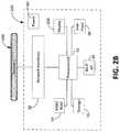
- FIG. 2Bdepicts a block diagram of a test instrument used in the system of FIG. 1 ;
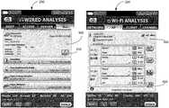
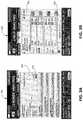
- FIGS. 3A and 3Bdepict screens shots of the test instrument used in the system of FIG. 1 ;
- FIG. 4is a flowchart of operational steps of a test instrument used in the system of FIG. 1 .
- the embodiments of this invention as discussed beloware preferably a software algorithm, program or code residing on computer useable medium having control logic for enabling execution on a machine having a computer processor.
- the machinetypically includes memory storage configured to provide output from execution of the computer algorithm or program.
- the term “software”is meant to be synonymous with any code or program that can be in a processor of a host computer, regardless of whether the implementation is in hardware, firmware or as a software computer product available on a disc, a memory storage device, or for download from a remote machine.
- the embodiments described hereininclude such software to implement the equations, relationships and algorithms described above.
- One skilled in the artwill appreciate further features and advantages of the invention based on the above-described embodiments. Accordingly, the invention is not to be limited by what has been particularly shown and described, except as indicated by the appended claims.
- the inventiongenerally relates to a network test instrument ( 200 , FIGS. 1 and 2A ), method of operation ( 400 , FIG. 4 ), and graphical interface ( 250 , FIG. 2A ) such that when the network test instrument 200 through both wireless discovery 30 (e.g., via 802.11) and wired discovery 32 (e.g., via 802.3) methods detect a network device ( 10 , FIG. 1 ) in a test network 100 , a user, via GUI 250 , selects the device 10 from a summary device list presented in a GUI 250 preferably categorized either by a wired analysis listing ( 300 , FIG.
- wireless discovery 30e.g., via 802.11
- wired discovery 32e.g., via 802.3
- the network test instrument 200being adapted and configured to query both a wired analysis database 260 and a Wi-Fi analysis database 270 for the existence of an entry that preferably corresponds to a MAC address associated with the selected device 10 . If the device MAC address (e.g., the device 10 ) is found in both databases 260 , 270 , a cross link navigation symbol/button 310 is presented in the GUI 250 . Selecting the cross link navigation symbol/button ( 310 , FIG. 3A ) terminates the current UI window regarding, for instance, wired details (window 300 on GUI 250 ) so as to display device details (window 350 on GUI 250 ) for the selected device 10 for the complementary wireless network type.
- network test device 200detects and acquires diagnostic information of a plurality of network devices 10 , 12 , 14 coupled to a network (e.g., a Local Area Network LAN) 100 .
- network 100may be wirelessly (via preferably a 802.11 link) and/or wired (via preferably a 802.3 link) connected to plural network devices 10 , 12 , 14 , etc., which communicate over a network 100 by preferably sending and receiving network traffic 15 preferably via interaction with server 20 or other networking components thereof.
- the traffic 15may be sent in packet form, with varying protocols and formatting thereof.
- Examples of the network devices 10 , 12 , 14 , etc.include (and are not limited to) multiple network devices such as routers, switches, hubs, servers, client computers (e.g., desktop PCs, laptops, workstations), and peripheral devices networked together across a network 100 such as for instance a local area network (LAN) and/or a wide area network (WAN).
- LANlocal area network
- WANwide area network
- datais typically exchanged between a requesting device, such as a client 10 , and a responding device, such as a server 20 .
- a network test instrument 200connects to the network 100 via both wirelessly 30 (e.g., via preferably 802.11 techniques) and via a wired connection 32 (e.g., via preferably 802.3 techniques). It is noted, network test instrument 200 in an illustrated embodiment wirelessly connects 30 via a Wi-Fi connection used by network 100 , and establishes a wired connection 23 to network 100 via preferably a shared hub 34 or like switch component type connected in network 100 .
- test instrument 200in accordance with an illustrated embodiment may use a first process in which the test instrument 100 uses ARP and PING sweeps with network 100 to acquire AP MAC and BSSID network device information.
- Test instrument 200may additionally use a second process in which test instrument 200 utilizes SNMP BSSID queries with network 100 to acquire AP BSSID network device information.
- network test instrument 200is adapted and configured, through both wireless discovery 30 (e.g., via 802.11) and wired discovery 32 (e.g., via 802.3) methods, to detect and acquire diagnostic device information from network devices 10 , 12 , 14 , etc., coupled either wirelessly or by wire to test network 100 .
- network device Layer 1 and 2 informationis preferably acquired via a wireless connection (e.g., 802.11) and network device Layer 2 and 3 information is preferably acquired via a wired connection (e.g., 802.3).
- Layer 1 and 2 information acquired via a 802.11 connectiontypically includes information relating to: signal strength; associated Service Set Identification (SSID); Basic SSID (BSSID); and linked Access Point (AP), etc.
- Layer 2 and 3 information acquired via an 802.3 connectiontypically includes information relating to MAC addresses, IPv4 and/or IPv6 addresses, device name, Domain Name Server (DNS); NETBIOS and/or SNMP, etc.
- Network test instrument 200includes a user interface 250 enabling a user to interact with the network test instrument 200 , and to operate the instrument 200 and obtain data therefrom, whether at the location of installation or remotely from the physical location of network attachment.
- Network test instrument 200preferably includes hardware and software, CPU, memory, interfaces and the like to operate, connect to, monitor and acquire network device 10 , 12 , 14 on the network 100 , as well as performing various testing and measurement operations, transmitting and receiving data and the like.
- One or more instruments 200may be operating at various locations on the network 100 , providing measurement data at the various locations, which may be forwarded and/or stored for analysis.
- Network test instrument 200preferably includes a software driven analysis engine 22 which acquires diagnostic information from network devices 10 , 12 , 14 , via either wirelessly 30 (e.g., 802.11) or wired 32 (e.g., 802.3), and preferably stores data received via a wireless connection 30 in a first database/memory location 260 for wireless (e.g., 802.11) captured data, and preferably stores data received via a wired connection 32 in a second database/memory location 270 for wired (e.g., 802.3) captured data.
- wirelessly 30e.g. 802.11
- wired 32e.g. 802.3
- Instrument 200may include network interfaces 50 which attach the instrument 200 to a network 100 via multiple ports.
- Instrument 200further preferably includes: one or more processors 52 for operating the instrument 200 ; memory such as RAM/ROM 54 (e.g., databases 260 , 270 ); persistent storage 56 ; GUI display 250 user input devices 58 (such as, for example, keyboard, mouse or other pointing devices, touch screen, etc.); power supply 60 which may include battery or AC power supplies; a Wi-Fi transceiver 60 which wirelessly (e.g., via 802.11) attaches instrument 200 to network 100 and other external devices.
- processors 52for operating the instrument 200
- memorysuch as RAM/ROM 54 (e.g., databases 260 , 270 ); persistent storage 56 ; GUI display 250 user input devices 58 (such as, for example, keyboard, mouse or other pointing devices, touch screen, etc.); power supply 60 which may include battery or AC power supplies; a Wi-Fi transceiver 60 which wirelessly (e.g., via 802.11) attach
- network test instrument 200may be utilized with the OneTouchTM AT Network Assistant handheld instrument provided by Fluke Networks®, as shown in FIG. 2A .
- the OneTouchTM AT Network Assistant 200is essentially an all-in-one Gigabit Ethernet diagnostic instrument adapted and configured for copper, fiber optic and Wi-Fi networks. Operational aspects can be found in commonly assigned U.S. Pat. No. 5,919,248 (filed Mar. 25, 1997) and U.S. Pat. No. 6,064,372 (filed Nov. 27, 1996), and U.S. Patent Publication Nos.: 2012/0291115 (filed May 12, 2011) and 2013/0046809, all of which are incorporated herein by reference in their entirety.
- instrument 200provides a client view (via GUI 250 ) of network performance enabling a user to expeditiously troubleshoot and solve problems.
- Certain operational and functional features of network test instrument 200include (and are not limited to): an integrated Ethernet tester for copper, fiber optic and Wi-Fi in which instrument 200 preferably includes multiple 10/100/1000 Mbps RJ-45 Ethernet test ports, multiple 100/1000 Mbps SFP fiber optic transceiver ports and an internal 802.11 a/b/g/n dual band radio to simultaneously test wired Ethernet and wireless Wi-Fi networks.
- Instrument 200is adapted and operational to conduct wired network analysis whereby instrument 200 provides automated discovery of copper and fiber-connected devices (e.g., 10 , 12 ) and key device attributes to enable sorting by attributes to obtain multiple views into the wired network 100 . For example, sort by IPv4 or IPv6 address to identify used and available addresses. Instrument 200 is adapted and operational to conduct Wi-Fi network analysis whereby instrument 200 provides automated discovery of Wi-Fi devices (e.g., 12 , 14 ) and key device attributes to enable sorting by attributes to obtain multiple views into the wireless network 100 . For example, sort by signal strength to troubleshoot Wi-Fi coverage issues. Sort by MAC manufacturer to discover Wi-Fi devices (e.g., 10 , 14 ) by type, sort by channel to identify channel spacing problems and sort by authorization status to find potential security violations.
- wired network analysiswhereby instrument 200 provides automated discovery of copper and fiber-connected devices (e.g., 10 , 12 ) and key device attributes to enable sorting by attributes to obtain multiple views into the wired network
- a method of operation 400 for instrument 200will now be discussed in accordance with certain illustrated embodiments for instrument 200 . It is noted that the order of steps shown in FIG. 4 for method 400 is not required, so in principle, the various steps may be performed out of the illustrated order. Also certain steps may be skipped, different steps may be added or substituted, or selected steps or groups of steps may be performed in a separate application following the embodiments described herein.
- a illustrative method of operation (referenced generally by numeral 400 ) of instrument 200includes establishing a data connection between instrument 200 and each device ( 10 , 12 , 14 , etc.,) connected to a network 100 via either one or both of a wireless connection (e.g., via a 802.11 connection) and/or a wired connection (e.g., via a 802.3 connection) to the network 100 .
- a wireless connectione.g., via a 802.11 connection
- a wired connectione.g., via a 802.3 connection
- information acquired via a wireless (e.g., 802.11) connection to device 10will results in capture of information available wirelessly including for instance (but not limited to) the aforesaid layer 1 and 2 device information.
- information acquired via a wired (e.g., 802.3) connection to device 10will results in capture of information available via a wired connection, including for instance (but not limited to) the aforesaid Layer 2 and 3 device information.
- step 420device 10 information acquired via a wireless connection (e.g., 802.11) is preferably stored in a first memory location (e.g., database 260 ) for information captured wirelessly, and information acquired via a wired connection (e.g., 802.3) is preferably stored in a second memory location (e.g., database 270 ) for wired captured information.
- a wireless connectione.g. 802.11
- a wired connectione.g., 802.3
- the wirelessly captured informationis stored in the aforesaid first memory location (e.g., database 260 ) for wirelessly captured information and the wired captured information is stored in the aforesaid second memory location (e.g., database 270 ) for wired captured information.
- the aforesaid device informationis stored in both the wireless memory location/database ( 260 ) and the wired memory location/database ( 270 ) in accordance with a selected MAC address for a given device (e.g., device 10 ).
- MAC addressis a uniquely identifying network address assigned to network interfaces for communications on a physical network, (e.g., network 100 ).
- MAC addressesare used for numerous network technologies and IEEE 802 network technologies, including Ethernet.
- MAC addressesare typically used in the media access control protocol sublayer of the Open System Interconnection (OSI) reference model.
- OSIOpen System Interconnection
- the wired databasepreferably uses SNMP, ARP, NetBEUI, ICMP, and other protocols to elicit as much information as possible about each device. This act of sending queries and receiving answers is called “Active Discovery” because devices are being actively communicated with on the network. Through the information gained by active discovery, the wired database can determine whether a device has multiple MAC addresses and/or IP addresses.
- the wireless databaseis populated primarily by listening to network packets (as opposed to actively communicating with devices to elicit information). This listening method of gathering information is termed “Passive Discovery”.
- the wireless databasepreferably uses a matching technique algorithm to determine whether two different wireless MAC addresses are actually the same device.
- both the wired and wireless databasesuse Active and Passive discovery, but wireless uses primarily Passive and wired uses primarily Active. Additionally, both the wired and wireless databases can merge multiple MAC addresses into a single device, or in other words, devices can have multiple MAC addresses. Additionally, it is to be appreciated that both the wired and wireless databases can determine the IP address(es) of devices.
- control logicassumes that if any of the multiple MAC addresses of a device in one database matches any of the multiple addresses of one device in the other database means that the two devices are in fact the same device. It is further assumed that if any of the multiple MAC addresses of a device in the wired database matches any of the multiple addresses of one device in the wireless database using the aforesaid matching technique mentioned above, this is indicative that the two devices are the same device.
- any of the multiple IP addresses of a device in one database matching any of the multiple IP addresses of one device in the other databaseis indicative that the two devices are likely the same device.
- the reason that IP addresses only lead to a likelihood of a matching deviceis because some wireless devices actually share an IP address, and further confirmation is required to verify the match—which confirmation can come through SNMP queries.
- Instrument 200is further operational and functional, via its GUI ( 250 ), to provide a listing of network devices (e.g., 10 , 12 ) discovered via a wired network connection ( FIG. 3A ), or upon user preference, a listing of network devices (e.g., 10 , 14 ) discovered via a wireless network connection ( FIG. 3B ), step 425 .
- a userselects which aforesaid device listing to view (e.g., the listing of devices captured via a wired connection— FIG. 3A )
- a userpreferably selects a listed device (e.g., device 10 ), step 430 .
- the network/captured information relating to that selected deviceis then retrieved from the appropriate wired or wirelessly captured memory location/database (e.g., database 270 for wired captured information) and is displayed to the user via the instrument GUI 250 (e.g., window segment 300 of FIG. 3A ), step 435 .
- the instrument GUI 250e.g., window segment 300 of FIG. 3A
- instrument 200determines if information was also captured for the selected device (e.g., device 10 ) via the other connection method (e.g., wireless), step 440 .
- thisis accomplished by instrument 200 through determining if a matching MAC address for the selected device (e.g., device 10 ) (step 430 ) is used to store information in the other memory location/database (e.g., database 260 for wireless captured information) by querying said other memory location/database (e.g., database 260 ).
- the other memory location/databasee.g., database 260 for wireless captured information
- step 430device/network information for the selected device (e.g., device 10 ) was captured both via a wired and wireless connection with instrument 200 , and indication is presented in the GUI 250 (e.g., symbols 310 , 360 ) indicating information was also captured via the other connection method for the selected device (e.g., device 10 ), step 445 .
- this indicationcauses instrument 200 to retrieve the network/captured information relating to the selected device (e.g., device 10 ) from the memory/database (e.g., database 260 for wireless captured information) relating to this other (e.g., wireless) connection method so as to then be displayed via the instrument GUI 250 (e.g., window segment 350 of FIG. 3B ), step 450 .
- the memory/databasee.g., database 260 for wireless captured information
- this GUI display(e.g., window 350 ) also provides indication (e.g., symbol 360 ) indicating information was captured via the other connection method (e.g., wired connection) for the selected device (e.g., device 10 ), whereupon user selection of this indication (e.g., symbol 360 ) causes instrument 200 to retrieve the network/captured information relating to the selected device (e.g., device 10 ) from the memory/database (e.g., database 270 for wireless captured information) relating to this other (e.g., wired) connection method.
- the memory/databasee.g., database 270 for wireless captured information
- wireless discovery details window 350( FIG. 3B ) for a specific 802.11 device 10 is displayed
- selection of the cross link filter button/indication 360pushes the 802.11 discovery details window 350 down on GUI 250 of instrument 200 and raises the wired discovery details window 310 ( FIG. 3A ) on GUI 250 on instrument 200 for the same device 10 .
- Selection of a cross link button/indication 310 on the wired discovery details window 300then restores the original wireless discovery widow 350 details view ( FIG. 3B ).
- Optional embodiments of the above illustrated embodimentsmay also be said to broadly consist in the parts, elements and features referred to or indicated herein, individually or collectively, in any or all combinations of two or more of the parts, elements or features, and wherein specific integers are mentioned herein which have known equivalents in the art to which the invention relates, such known equivalents are deemed to be incorporated herein as if individually set forth.
- the abovepresents a description of a best mode contemplated for carrying out illustrated embodiments and of the manner and process of making and using it in such full, clear, concise, and exact terms as to enable any person skilled in the art to which it pertains to make and use/practice the illustrated embodiments.
- the illustrated embodimentsare, however, susceptible to modifications and alternative method steps from those discussed above that are fully equivalent. Consequently, they are not limited to the particular embodiments disclosed. On the contrary, the illustrated embodiments encompass all modifications and alternative constructions and methods coming within the spirit and scope of the present invention.
Landscapes
- Engineering & Computer Science (AREA)
- Computer Networks & Wireless Communication (AREA)
- Signal Processing (AREA)
- Human Computer Interaction (AREA)
- Mobile Radio Communication Systems (AREA)
- General Engineering & Computer Science (AREA)
- Theoretical Computer Science (AREA)
- Physics & Mathematics (AREA)
- General Physics & Mathematics (AREA)
Abstract
Description
Claims (17)
Priority Applications (1)
| Application Number | Priority Date | Filing Date | Title |
|---|---|---|---|
| US15/602,310US10917311B2 (en) | 2013-04-12 | 2017-05-23 | Network test instrument |
Applications Claiming Priority (3)
| Application Number | Priority Date | Filing Date | Title |
|---|---|---|---|
| US201361811573P | 2013-04-12 | 2013-04-12 | |
| US13/874,104US20140310604A1 (en) | 2013-04-12 | 2013-04-30 | Network test instrument |
| US15/602,310US10917311B2 (en) | 2013-04-12 | 2017-05-23 | Network test instrument |
Related Parent Applications (1)
| Application Number | Title | Priority Date | Filing Date |
|---|---|---|---|
| US13/874,104ContinuationUS20140310604A1 (en) | 2013-04-12 | 2013-04-30 | Network test instrument |
Publications (2)
| Publication Number | Publication Date |
|---|---|
| US20170264502A1 US20170264502A1 (en) | 2017-09-14 |
| US10917311B2true US10917311B2 (en) | 2021-02-09 |
Family
ID=51687667
Family Applications (2)
| Application Number | Title | Priority Date | Filing Date |
|---|---|---|---|
| US13/874,104AbandonedUS20140310604A1 (en) | 2013-04-12 | 2013-04-30 | Network test instrument |
| US15/602,310Active2033-12-16US10917311B2 (en) | 2013-04-12 | 2017-05-23 | Network test instrument |
Family Applications Before (1)
| Application Number | Title | Priority Date | Filing Date |
|---|---|---|---|
| US13/874,104AbandonedUS20140310604A1 (en) | 2013-04-12 | 2013-04-30 | Network test instrument |
Country Status (1)
| Country | Link |
|---|---|
| US (2) | US20140310604A1 (en) |
Cited By (1)
| Publication number | Priority date | Publication date | Assignee | Title |
|---|---|---|---|---|
| US11240749B2 (en)* | 2014-06-24 | 2022-02-01 | Arris Enterprises Llc | Provisioning radios associated with access points for testing a wireless network |
Families Citing this family (10)
| Publication number | Priority date | Publication date | Assignee | Title |
|---|---|---|---|---|
| CN104618511A (en)* | 2015-02-26 | 2015-05-13 | 小米科技有限责任公司 | Intelligent device detection method and device |
| CN106301993A (en)* | 2015-06-12 | 2017-01-04 | 中兴通讯股份有限公司 | A kind of method and apparatus of test router |
| US10404559B2 (en)* | 2015-07-17 | 2019-09-03 | Dataprobe Inc. | Apparatus and system for automatically rebooting an electronically powered device via power over ethernet |
| US11258679B2 (en) | 2015-07-28 | 2022-02-22 | Spirent Communications, Inc. | Systems and methods for automated testing of MoCA networks |
| US10382314B2 (en)* | 2016-03-11 | 2019-08-13 | Spirent Communications, Inc. | Systems and methods for automated testing of MoCA networks |
| US10129102B2 (en) | 2016-05-11 | 2018-11-13 | Spirent Communications, Inc. | Service based testing |
| US10498440B2 (en)* | 2015-10-12 | 2019-12-03 | Viavi Solutions, Inc. | Network test instrument supporting hybrid fiber coax and RF over glass installations and method of using same |
| US10033621B2 (en)* | 2015-12-15 | 2018-07-24 | At&T Intellectual Property I, L.P. | Method and apparatus for initiating internet connection speed testing on a residential gateway |
| US10433134B2 (en)* | 2017-01-24 | 2019-10-01 | Arris Enterprises Llc | Video gateway as an internet of things mesh enhancer apparatus and method |
| CN112653598B (en)* | 2020-12-18 | 2022-02-22 | 迈普通信技术股份有限公司 | Automatic testing method, device, equipment and readable storage medium |
Citations (34)
| Publication number | Priority date | Publication date | Assignee | Title |
|---|---|---|---|---|
| US20020075326A1 (en)* | 2000-12-20 | 2002-06-20 | Dowell Allen | Method and system of displaying telecommunication trace diagnostic information |
| US20020111924A1 (en)* | 2000-11-14 | 2002-08-15 | Tokheim Corporation | Fuel dispensing system utilizing XML processors |
| US20020144187A1 (en) | 2001-01-24 | 2002-10-03 | Morgan Dennis A. | Consumer network diagnostic agent |
| US6609152B1 (en) | 1998-11-02 | 2003-08-19 | Canon Kabushiki Kaisha | System for avoiding the assignment of duplicate MAC addresses to network interface devices |
| US20040255192A1 (en)* | 2003-01-30 | 2004-12-16 | Hiroyuki Watanabe | Information processing apparatus and network connection diagnostic method used in the same apparatus |
| US6952421B1 (en) | 1999-10-07 | 2005-10-04 | Cisco Technology, Inc. | Switched Ethernet path detection |
| US20060098589A1 (en) | 2004-10-22 | 2006-05-11 | Cisco Technology, Inc. | Forwarding table reduction and multipath network forwarding |
| US20060203815A1 (en) | 2005-03-10 | 2006-09-14 | Alain Couillard | Compliance verification and OSI layer 2 connection of device using said compliance verification |
| US20070081549A1 (en)* | 2005-10-12 | 2007-04-12 | Finisar Corporation | Network tap/aggregator configured for power over ethernet operation |
| US20070150819A1 (en)* | 2005-12-09 | 2007-06-28 | Mks Instruments, Inc. | Graphical User Interface |
| US20070211697A1 (en) | 2006-03-13 | 2007-09-13 | Finisar Corporation | Method of analyzing network with generated traffic |
| US20070211696A1 (en) | 2006-03-13 | 2007-09-13 | Finisar Corporation | Method of generating network traffic |
| US7278104B1 (en) | 2000-11-02 | 2007-10-02 | Lucent Technologies Inc. | Graphical user interface for managing network elements |
| US20070233858A1 (en)* | 2006-04-03 | 2007-10-04 | Donald Goff | Diagnostic access system |
| US20070240071A1 (en) | 2006-04-11 | 2007-10-11 | Invensys Systems, Inc. | System management user interface providing user access to status information for process control system equipment including a search function |
| US7370236B2 (en)* | 2001-11-28 | 2008-05-06 | Sony Deutschland Gmbh | Method for remotely diagnosing devices |
| US20090059814A1 (en)* | 2007-08-31 | 2009-03-05 | Fisher-Rosemount Sytems, Inc. | Configuring and Optimizing a Wireless Mesh Network |
| US20090058857A1 (en)* | 2007-09-04 | 2009-03-05 | Andrew John Ballantyne | Network trouble-tickets displayed as dynamic multi-dimensional graph |
| US20090113244A1 (en)* | 2007-10-30 | 2009-04-30 | Cisco Technology, Inc. | Diagnostic Functionality for Wireless Client Connectivity Problems in Wireless Networks |
| US20090210935A1 (en) | 2008-02-20 | 2009-08-20 | Jamie Alan Miley | Scanning Apparatus and System for Tracking Computer Hardware |
| US20100138750A1 (en) | 2008-11-30 | 2010-06-03 | Xtera Communications, Inc. | Presenting network performance data in the context of a map of path model objects |
| US20100187903A1 (en)* | 2007-12-17 | 2010-07-29 | Wael William Diab | Method and system for vehicular power distribution utilizing power over ethernet in an aircraft |
| US20110149720A1 (en) | 2009-12-17 | 2011-06-23 | Verizon Patent And Licensing, Inc. | System for and method of performing residential gateway diagnostics and corrective actions |
| US20110265116A1 (en) | 2010-04-23 | 2011-10-27 | Peter Stern | Zone control methods and apparatus |
| US20120079100A1 (en)* | 2010-05-28 | 2012-03-29 | Motorola Mobility, Inc. | Electronic device diagnostic systems and methods |
| US20120209934A1 (en)* | 2009-06-18 | 2012-08-16 | Smedman Bjorn | Access point, a server and a system for distributing an unlimited number of virtual ieee 802.11 wireless networks through a heterogeneous infrastructure |
| US20120210000A1 (en) | 2011-02-15 | 2012-08-16 | International Business Machines Corporation | Registering Devices For Network Access |
| US20130019298A1 (en) | 2010-03-30 | 2013-01-17 | British Telecommunications Public Limited Company | Method and system for authenticating a point of access |
| US8437790B1 (en) | 2011-12-08 | 2013-05-07 | Microsoft Corporation | Location determination for white space utilization |
| US20130286864A1 (en)* | 2012-04-30 | 2013-10-31 | Cisco Technology, Inc. | Computer system communication channel diagnostics |
| US20140032746A1 (en)* | 2012-07-26 | 2014-01-30 | Infosys Limited | Methods for managing network elements within a network environment and devices thereof |
| US20140259074A1 (en)* | 2006-12-29 | 2014-09-11 | Prodea Systems, Inc. | Display inserts, overlays, and graphical user interfaces for multimedia systems |
| US9479341B2 (en)* | 2006-08-22 | 2016-10-25 | Centurylink Intellectual Property Llc | System and method for initiating diagnostics on a packet network node |
| US20160313776A1 (en)* | 2005-04-26 | 2016-10-27 | Accedian Networks Inc. | Power over ethernet management devices and connection between ethernet devices |
- 2013
- 2013-04-30USUS13/874,104patent/US20140310604A1/ennot_activeAbandoned
- 2017
- 2017-05-23USUS15/602,310patent/US10917311B2/enactiveActive
Patent Citations (35)
| Publication number | Priority date | Publication date | Assignee | Title |
|---|---|---|---|---|
| US6609152B1 (en) | 1998-11-02 | 2003-08-19 | Canon Kabushiki Kaisha | System for avoiding the assignment of duplicate MAC addresses to network interface devices |
| US6952421B1 (en) | 1999-10-07 | 2005-10-04 | Cisco Technology, Inc. | Switched Ethernet path detection |
| US7278104B1 (en) | 2000-11-02 | 2007-10-02 | Lucent Technologies Inc. | Graphical user interface for managing network elements |
| US20020111924A1 (en)* | 2000-11-14 | 2002-08-15 | Tokheim Corporation | Fuel dispensing system utilizing XML processors |
| US20020075326A1 (en)* | 2000-12-20 | 2002-06-20 | Dowell Allen | Method and system of displaying telecommunication trace diagnostic information |
| US20020144187A1 (en) | 2001-01-24 | 2002-10-03 | Morgan Dennis A. | Consumer network diagnostic agent |
| US7370236B2 (en)* | 2001-11-28 | 2008-05-06 | Sony Deutschland Gmbh | Method for remotely diagnosing devices |
| US20040255192A1 (en)* | 2003-01-30 | 2004-12-16 | Hiroyuki Watanabe | Information processing apparatus and network connection diagnostic method used in the same apparatus |
| US20060098589A1 (en) | 2004-10-22 | 2006-05-11 | Cisco Technology, Inc. | Forwarding table reduction and multipath network forwarding |
| US20060203815A1 (en) | 2005-03-10 | 2006-09-14 | Alain Couillard | Compliance verification and OSI layer 2 connection of device using said compliance verification |
| US20160313776A1 (en)* | 2005-04-26 | 2016-10-27 | Accedian Networks Inc. | Power over ethernet management devices and connection between ethernet devices |
| US20070081549A1 (en)* | 2005-10-12 | 2007-04-12 | Finisar Corporation | Network tap/aggregator configured for power over ethernet operation |
| US20070150819A1 (en)* | 2005-12-09 | 2007-06-28 | Mks Instruments, Inc. | Graphical User Interface |
| US20070211697A1 (en) | 2006-03-13 | 2007-09-13 | Finisar Corporation | Method of analyzing network with generated traffic |
| US20070211696A1 (en) | 2006-03-13 | 2007-09-13 | Finisar Corporation | Method of generating network traffic |
| US20070233858A1 (en)* | 2006-04-03 | 2007-10-04 | Donald Goff | Diagnostic access system |
| US20070240071A1 (en) | 2006-04-11 | 2007-10-11 | Invensys Systems, Inc. | System management user interface providing user access to status information for process control system equipment including a search function |
| US9479341B2 (en)* | 2006-08-22 | 2016-10-25 | Centurylink Intellectual Property Llc | System and method for initiating diagnostics on a packet network node |
| US20140259074A1 (en)* | 2006-12-29 | 2014-09-11 | Prodea Systems, Inc. | Display inserts, overlays, and graphical user interfaces for multimedia systems |
| US20090059814A1 (en)* | 2007-08-31 | 2009-03-05 | Fisher-Rosemount Sytems, Inc. | Configuring and Optimizing a Wireless Mesh Network |
| US20090058857A1 (en)* | 2007-09-04 | 2009-03-05 | Andrew John Ballantyne | Network trouble-tickets displayed as dynamic multi-dimensional graph |
| US20090113244A1 (en)* | 2007-10-30 | 2009-04-30 | Cisco Technology, Inc. | Diagnostic Functionality for Wireless Client Connectivity Problems in Wireless Networks |
| US20100187903A1 (en)* | 2007-12-17 | 2010-07-29 | Wael William Diab | Method and system for vehicular power distribution utilizing power over ethernet in an aircraft |
| US20090210935A1 (en) | 2008-02-20 | 2009-08-20 | Jamie Alan Miley | Scanning Apparatus and System for Tracking Computer Hardware |
| US20100138750A1 (en) | 2008-11-30 | 2010-06-03 | Xtera Communications, Inc. | Presenting network performance data in the context of a map of path model objects |
| US20120209934A1 (en)* | 2009-06-18 | 2012-08-16 | Smedman Bjorn | Access point, a server and a system for distributing an unlimited number of virtual ieee 802.11 wireless networks through a heterogeneous infrastructure |
| US20110149720A1 (en) | 2009-12-17 | 2011-06-23 | Verizon Patent And Licensing, Inc. | System for and method of performing residential gateway diagnostics and corrective actions |
| US20130019298A1 (en) | 2010-03-30 | 2013-01-17 | British Telecommunications Public Limited Company | Method and system for authenticating a point of access |
| US20110265116A1 (en) | 2010-04-23 | 2011-10-27 | Peter Stern | Zone control methods and apparatus |
| US20120079100A1 (en)* | 2010-05-28 | 2012-03-29 | Motorola Mobility, Inc. | Electronic device diagnostic systems and methods |
| US20120210000A1 (en) | 2011-02-15 | 2012-08-16 | International Business Machines Corporation | Registering Devices For Network Access |
| US8437790B1 (en) | 2011-12-08 | 2013-05-07 | Microsoft Corporation | Location determination for white space utilization |
| US9094339B2 (en)* | 2012-04-30 | 2015-07-28 | Cisco Technology, Inc. | Computer system communication channel diagnostics |
| US20130286864A1 (en)* | 2012-04-30 | 2013-10-31 | Cisco Technology, Inc. | Computer system communication channel diagnostics |
| US20140032746A1 (en)* | 2012-07-26 | 2014-01-30 | Infosys Limited | Methods for managing network elements within a network environment and devices thereof |
Non-Patent Citations (5)
| Title |
|---|
| Final Office Action issued in related U.S. Appl. No. 13/874,104 dated Mar. 10, 2016. |
| Final Office Action issued in related U.S. Appl. No. 13/874,104 dated Nov. 16, 2016. |
| Non-Final Office Action issued in related U.S. Appl. No. 13/874,104 dated Jul. 27, 2015. |
| Non-Final Office Action issued in related U.S. Appl. No. 13/874,104 dated Jul. 28, 2016. |
| Notice of Allowance issued in related U.S. Appl. No. 13/874,104 dated Mar. 10, 2017. |
Cited By (1)
| Publication number | Priority date | Publication date | Assignee | Title |
|---|---|---|---|---|
| US11240749B2 (en)* | 2014-06-24 | 2022-02-01 | Arris Enterprises Llc | Provisioning radios associated with access points for testing a wireless network |
Also Published As
| Publication number | Publication date |
|---|---|
| US20140310604A1 (en) | 2014-10-16 |
| US20170264502A1 (en) | 2017-09-14 |
Similar Documents
| Publication | Publication Date | Title |
|---|---|---|
| US10917311B2 (en) | Network test instrument | |
| EP1985128B1 (en) | Troubleshooting link and protocol in a wireless network | |
| Sivanathan et al. | Can we classify an iot device using tcp port scan? | |
| US9019944B2 (en) | Diagnosing and resolving wireless network malfunctions | |
| US7747740B2 (en) | Troubleshooting of Wireless Client Connectivity Problems in Wireless Networks | |
| US10367713B2 (en) | Cloud based system and method for managing testing configurations for cable test devices | |
| US7516049B2 (en) | Wireless performance analysis system | |
| US10812362B2 (en) | Client device and method for analysis of a predetermined set of parameters associated with radio coupling to a WLAN | |
| US20250048240A1 (en) | Method and apparatus for wireless device identification and device type based diagnostics and optimization | |
| CN101448277A (en) | Method, system and device for processing wireless access network faults | |
| JP4650634B2 (en) | Wireless network monitoring device and monitoring system | |
| CN110337103A (en) | A kind of connectionless data hided transmission method based on 802.11 agreements | |
| CN108124280B (en) | Monitoring and diagnosis system and network monitoring and diagnosis method | |
| US11665630B2 (en) | Identification of wireless transmissions carried by a wireless network | |
| WO2014101025A1 (en) | Terminal debugging method, device, and equipment | |
| KR20080058609A (en) | Integrated WLAN protocol analysis equipment, analysis method and training method using the same | |
| WO2023287666A1 (en) | Methods and systems for network diagnostic |
Legal Events
| Date | Code | Title | Description |
|---|---|---|---|
| STPP | Information on status: patent application and granting procedure in general | Free format text:DOCKETED NEW CASE - READY FOR EXAMINATION | |
| STPP | Information on status: patent application and granting procedure in general | Free format text:NON FINAL ACTION MAILED | |
| STPP | Information on status: patent application and granting procedure in general | Free format text:RESPONSE TO NON-FINAL OFFICE ACTION ENTERED AND FORWARDED TO EXAMINER | |
| STPP | Information on status: patent application and granting procedure in general | Free format text:FINAL REJECTION MAILED | |
| AS | Assignment | Owner name:LINKRUNNER, LLC, CALIFORNIA Free format text:ASSIGNMENT OF ASSIGNORS INTEREST;ASSIGNOR:AIRMAGNET, INC.;REEL/FRAME:050956/0394 Effective date:20190709 | |
| STPP | Information on status: patent application and granting procedure in general | Free format text:NON FINAL ACTION MAILED | |
| STPP | Information on status: patent application and granting procedure in general | Free format text:RESPONSE TO NON-FINAL OFFICE ACTION ENTERED AND FORWARDED TO EXAMINER | |
| STPP | Information on status: patent application and granting procedure in general | Free format text:DOCKETED NEW CASE - READY FOR EXAMINATION | |
| STPP | Information on status: patent application and granting procedure in general | Free format text:AWAITING TC RESP., ISSUE FEE NOT PAID | |
| AS | Assignment | Owner name:NETALLY, LLC, COLORADO Free format text:CHANGE OF NAME;ASSIGNOR:LINKRUNNER, LLC;REEL/FRAME:054769/0958 Effective date:20200810 | |
| STCF | Information on status: patent grant | Free format text:PATENTED CASE | |
| MAFP | Maintenance fee payment | Free format text:PAYMENT OF MAINTENANCE FEE, 4TH YEAR, LARGE ENTITY (ORIGINAL EVENT CODE: M1551); ENTITY STATUS OF PATENT OWNER: LARGE ENTITY Year of fee payment:4 |