US10917167B2 - MC-CDMA with low peak-to-average power ratio multi-carrier waveform - Google Patents
MC-CDMA with low peak-to-average power ratio multi-carrier waveformDownload PDFInfo
- Publication number
- US10917167B2 US10917167B2US15/164,388US201615164388AUS10917167B2US 10917167 B2US10917167 B2US 10917167B2US 201615164388 AUS201615164388 AUS 201615164388AUS 10917167 B2US10917167 B2US 10917167B2
- Authority
- US
- United States
- Prior art keywords
- spreading
- spreading sequence
- sequences
- data
- zero subcarrier
- Prior art date
- Legal status (The legal status is an assumption and is not a legal conclusion. Google has not performed a legal analysis and makes no representation as to the accuracy of the status listed.)
- Active
Links
- 230000007480spreadingEffects0.000claimsabstractdescription301
- 238000000034methodMethods0.000claimsabstractdescription37
- 238000004891communicationMethods0.000claimsabstractdescription36
- 230000005540biological transmissionEffects0.000description20
- 239000011159matrix materialSubstances0.000description8
- 230000000875corresponding effectEffects0.000description7
- 238000013507mappingMethods0.000description7
- 230000006870functionEffects0.000description6
- 238000010586diagramMethods0.000description5
- 230000011664signalingEffects0.000description5
- 230000002596correlated effectEffects0.000description4
- 230000000694effectsEffects0.000description4
- 238000013461designMethods0.000description3
- 238000001514detection methodMethods0.000description3
- 238000003491arrayMethods0.000description2
- 230000008901benefitEffects0.000description2
- 230000000295complement effectEffects0.000description2
- 230000007774longtermEffects0.000description2
- 230000008450motivationEffects0.000description2
- 238000012545processingMethods0.000description2
- 238000012772sequence designMethods0.000description2
- 230000003595spectral effectEffects0.000description2
- 230000001413cellular effectEffects0.000description1
- 230000008859changeEffects0.000description1
- 125000004122cyclic groupChemical group0.000description1
- 238000005516engineering processMethods0.000description1
- 230000007246mechanismEffects0.000description1
- 230000000116mitigating effectEffects0.000description1
- 238000010295mobile communicationMethods0.000description1
- 238000012986modificationMethods0.000description1
- 230000004048modificationEffects0.000description1
- 238000007493shaping processMethods0.000description1
- 230000001131transforming effectEffects0.000description1
Images


Classifications
- H—ELECTRICITY
- H04—ELECTRIC COMMUNICATION TECHNIQUE
- H04L—TRANSMISSION OF DIGITAL INFORMATION, e.g. TELEGRAPHIC COMMUNICATION
- H04L27/00—Modulated-carrier systems
- H04L27/26—Systems using multi-frequency codes
- H04L27/2601—Multicarrier modulation systems
- H04L27/2614—Peak power aspects
- H—ELECTRICITY
- H04—ELECTRIC COMMUNICATION TECHNIQUE
- H04B—TRANSMISSION
- H04B7/00—Radio transmission systems, i.e. using radiation field
- H04B7/24—Radio transmission systems, i.e. using radiation field for communication between two or more posts
- H04B7/26—Radio transmission systems, i.e. using radiation field for communication between two or more posts at least one of which is mobile
- H04B7/2628—Radio transmission systems, i.e. using radiation field for communication between two or more posts at least one of which is mobile using code-division multiple access [CDMA] or spread spectrum multiple access [SSMA]
- H—ELECTRICITY
- H04—ELECTRIC COMMUNICATION TECHNIQUE
- H04J—MULTIPLEX COMMUNICATION
- H04J11/00—Orthogonal multiplex systems, e.g. using WALSH codes
- H04J11/0023—Interference mitigation or co-ordination
- H04J11/0026—Interference mitigation or co-ordination of multi-user interference
- H04J11/0036—Interference mitigation or co-ordination of multi-user interference at the receiver
- H04J11/004—Interference mitigation or co-ordination of multi-user interference at the receiver using regenerative subtractive interference cancellation
- H—ELECTRICITY
- H04—ELECTRIC COMMUNICATION TECHNIQUE
- H04L—TRANSMISSION OF DIGITAL INFORMATION, e.g. TELEGRAPHIC COMMUNICATION
- H04L27/00—Modulated-carrier systems
- H04L27/26—Systems using multi-frequency codes
- H04L27/2601—Multicarrier modulation systems
- H—ELECTRICITY
- H04—ELECTRIC COMMUNICATION TECHNIQUE
- H04L—TRANSMISSION OF DIGITAL INFORMATION, e.g. TELEGRAPHIC COMMUNICATION
- H04L27/00—Modulated-carrier systems
- H04L27/26—Systems using multi-frequency codes
- H04L27/2601—Multicarrier modulation systems
- H04L27/2626—Arrangements specific to the transmitter only
- H04L27/2627—Modulators
- H04L27/2634—Inverse fast Fourier transform [IFFT] or inverse discrete Fourier transform [IDFT] modulators in combination with other circuits for modulation
- H—ELECTRICITY
- H04—ELECTRIC COMMUNICATION TECHNIQUE
- H04L—TRANSMISSION OF DIGITAL INFORMATION, e.g. TELEGRAPHIC COMMUNICATION
- H04L5/00—Arrangements affording multiple use of the transmission path
- H04L5/0001—Arrangements for dividing the transmission path
- H04L5/0003—Two-dimensional division
- H04L5/0005—Time-frequency
- H04L5/0007—Time-frequency the frequencies being orthogonal, e.g. OFDM(A) or DMT
- H04L5/001—Time-frequency the frequencies being orthogonal, e.g. OFDM(A) or DMT the frequencies being arranged in component carriers
- H—ELECTRICITY
- H04—ELECTRIC COMMUNICATION TECHNIQUE
- H04L—TRANSMISSION OF DIGITAL INFORMATION, e.g. TELEGRAPHIC COMMUNICATION
- H04L5/00—Arrangements affording multiple use of the transmission path
- H04L5/0001—Arrangements for dividing the transmission path
- H04L5/0014—Three-dimensional division
- H04L5/0016—Time-frequency-code
- H04L5/0021—Time-frequency-code in which codes are applied as a frequency-domain sequences, e.g. MC-CDMA
Definitions
- the disclosurerelates generally to Multi-Carrier Code Division Multiple Access (MC-CDMA) techniques for Orthogonal Frequency Division Multiplexing (OFDM), and in particular embodiments to methods and systems for OFDM using MC-CDMA with single-carrier Peak-to-Average Power Ratio (PAPR).
- MC-CDMAMulti-Carrier Code Division Multiple Access
- PAPRPeak-to-Average Power Ratio
- PAPRis an important consideration in waveform design for wireless communication.
- LTELong Term Evolution
- DFT-S-OFDMDiscrete Fourier Transform Spread OFDM
- MTCMachine-Type Communication
- M2MMachine-to-Machine
- IoTInternet of Things
- DFT-S-OFDMis also called Single Carrier Frequency Division Multiple Access (SC-FDMA), because each DFT-spread sub-band signal uses a circularly convolved single carrier waveform.
- SC-FDMASingle Carrier Frequency Division Multiple Access
- One aspect of the present disclosureprovides a method for operating a device in a wireless network.
- the devicespreads data with a spreading sequence to generate multi-carrier spread data on subcarriers corresponding to non-zero subcarrier elements of the spreading sequence and transmits the multi-carrier spread data.
- the spreading sequencehas sparsity of non-zero subcarrier elements and an equal spacing between adjacent non-zero subcarrier elements.
- the waveform resulting from transmission of the multi-carrier spread datamay have a PAPR comparable to that of conventional single carrier transmission.
- the spreading sequencemay be selected from multiple spreading sequences that each has a respective equal spacing between adjacent non-zero subcarrier elements.
- the spreading sequences of the pluralitymay differ from one another in at least one of: sparsity level in the frequency domain; sparsity pattern in the frequency domain; and pulse offset in the time domain.
- spreading data with a spreading sequence to generate multi-carrier spread dataincludes spreading multiple data symbols with respective spreading sequences selected from the multiple spreading sequences.
- spreading multiple data symbols with respective spreading sequencesmay include spreading a first data symbol with a first spreading sequence, and spreading a second data symbol with a second spreading sequence, the first and second spreading sequences sharing a common sparsity pattern in the frequency domain and differing in pulse offset in the time domain.
- At least one non-zero subcarrier element in the spreading sequence used for spreading the datacollides with one non-zero subcarrier element of at least one of the other spreading sequences among the multiple spreading sequences, and at least one other non-zero subcarrier element in the spreading sequence used for spreading the data is different from one non-zero subcarrier element of at least one of the other spreading sequences.
- the spreading sequencehas a length corresponding to a number of subcarriers available in the wireless network.
- spreading data with a spreading sequence to generate multi-carrier spread dataincludes encoding binary data to generate a modulated data stream and mapping the modulated data stream onto non-zero subcarrier elements of the spreading sequence.
- encoding the binary data to generate a modulated data streammay involve applying a Fourier transform to the binary data.
- transmitting the multi-carrier spread dataincludes transforming the multi-carrier spread data to a time domain signal and transmitting the time domain signal.
- a value of the non-zero subcarrier elements in the spreading sequenceis equal to 1.
- the number of non-zero subcarrier elements in the spreading sequenceis greater than 2.
- the methodis implemented at user equipment (UE).
- UEuser equipment
- the methodmay be used by a UE for uplink random access.
- the spreaderincludes an encoder configured to encode binary data to generate a modulated data stream and a mapper configured to map the modulated data stream onto non-zero subcarrier elements of the spreading sequence.
- Yet another aspect of the present disclosureprovides a communication device configured to send data to a wireless network, the communication device including a transmitter according to the above aspect of the present disclosure.
- Still another aspect of the present disclosureprovides a method that includes assigning a first communication device a first spreading sequence for spreading data to generate first multi-carrier spread data on subcarriers corresponding to non-zero subcarrier elements of the first spreading sequence and assigning a second communication device a second spreading sequence for spreading data to generate second multi-carrier spread data on subcarriers corresponding to non-zero subcarrier elements of the second spreading sequence.
- the first spreading sequenceshaving sparsity of non-zero subcarrier elements and a first equal spacing between adjacent non-zero subcarrier elements.
- the second spreading sequencehaving a second equal spacing between adjacent non-zero subcarrier elements.
- the first and second spreading sequencesdiffering from one another in at least one of: sparsity level in the frequency domain; sparsity pattern in the frequency domain; and pulse offset in the time domain.
- the first equal spacing and the second equal spacingare equal. In other embodiments, the first equal spacing and the second equal spacing are different.
- assigning a first spreading sequence to the first communication deviceinvolves assigning the first communication device one or more spreading sequences from a first group of spreading sequences to spread one or more data symbols, each spreading sequence in the first group sharing a common sparsity pattern in the frequency domain and differing in pulse offset in the time domain.
- assigning a second spreading sequence to the second communication deviceinvolves assigning the second communication device one or more spreading sequences from the first group to spread one or more data symbols.
- the second communication deviceis assigned one or more spreading sequences from a second group of spreading sequences to spread one or more data symbols, each spreading sequence in the second group sharing a common sparsity pattern in the frequency domain and differing in pulse offset in the time domain, wherein the common sparsity pattern of the first group of spreading sequences is different from the common sparsity pattern of the second group of spreading sequences.
- FIG. 1is a block diagram of a communications network according to an embodiment of the present disclosure
- FIG. 2is a block diagram of a user device according to an embodiment of the present disclosure
- FIG. 3is a block diagram of a network node according to an embodiment of the present disclosure.
- FIG. 4shows frequency domain plots of low-density signature OFDM (LDS-OFDM) waveforms with single carrier PAPR according to an embodiment of the present disclosure
- FIG. 5is a block diagram illustrating a spreader according to an embodiment of the present disclosure
- FIG. 6shows frequency domain plots of two spreading sequences having different sparsity levels according to an embodiment of the present disclosure
- FIG. 7shows frequency domain plots of four spreading sequences having different sparsity patterns according to an embodiment of the present disclosure.
- FIG. 8shows frequency domain and time domain plots of eight spreading sequences having different sparsity patterns and/or time domain pulse offsets for multi-sequence transmission according to an embodiment of the present disclosure.
- DFT-S-OFDMtypically has lower PAPR than conventional OFDM.
- DFT-S-OFDMis unsuitable for MC-CDMA, because there is no mechanism in DFT-S-OFDM for mitigating signal collision between different devices.
- the present disclosuredescribes methods, devices and systems for spreading and transmitting data in a wireless communications system such that the resulting waveforms that are transmitted have low PAPR and mitigate signal collisions between different devices. Complementary receiving and decoding methods, devices and systems are also illustrated along with methods for generating spreading sequences. In some embodiments, a more efficient use of wireless communication resources for multiple devices is thus provided.
- This new waveformmay have one or more of the following properties:
- FIG. 1illustrates a communications network 100 comprising multiple user devices 102 A, 102 B, 102 C, 102 D and a network node 104 .
- the network 100may operate according to one or more communications or data standards or technologies including but not limited to fourth generation (4G) telecommunications networks such as Long-Term Evolution (LTE) networks, Universal Mobile Telecommunications System (UMTS) and other wireless or mobile communications networks.
- 4Gfourth generation
- LTELong-Term Evolution
- UMTSUniversal Mobile Telecommunications System
- the user devices 102sometimes known as user equipment (UEs), are generally any device capable of providing wireless communications such as a wireless transmit/receive unit (WTRU), mobile station (MS), smartphone, cellular telephone, sensor, or other wireless enabled computing or mobile device.
- WTRUwireless transmit/receive unit
- MSmobile station
- smartphonecellular telephone
- sensoror other wireless enabled computing or mobile device.
- the user devices 102comprise machines which perform other primary functions and have the capability to send, receive, or send and receive data in the communications network 100 .
- a machineincludes an apparatus or device with means to transmit and/or receive data through the communications network 100 but such apparatus or device is not typically operated by a user for the primary purpose of communications. It will be appreciated that the systems and methods described herein also may be applied to other low data rate transmission scenarios or applications and devices operating with unscheduled data transmissions.
- the network node 104may comprise a base station (BS), evolved Node B (eNB), access point (AP), or other network interface which functions as a transmission and/or reception point for user devices 102 in the network 100 .
- the network node 104is connected to a backhaul network 110 which enables data to be exchanged between the network node 104 and other remote networks, nodes and devices (not shown).
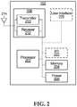
- FIG. 2shows one embodiment of a user device 102 for implementing the methods and modules described herein.
- the device 102may include a processor 202 , a memory 204 , a power source 206 and a wireless communications interface 208 for sending and receiving data in the communications network 100 , which components may or may not be arranged as shown in FIG. 2 .
- the wireless communications interface 208includes a transmitter 210 and a receiver 212 coupled to an antenna 214 . It will be appreciated that the functions of the wireless communications interface 208 may be carried out by different transceiver or modem components including multiple transmitter, receiver, digital signal processor (DSP) and antenna components or arrays.
- DSPdigital signal processor
- the user device 102includes a user interface 220 and various inputs/outputs (I/O) 222 such as a display, audio input, audio output, keypads, buttons, microphones or other inputs or outputs.
- the memory 204may store programming and/or instructions for the processor 202 including instructions for sending, receiving, processing and supporting different services and types of data, such as but not limited to video, VoIP calls, web browsing data, email and other text communications.
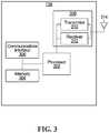
- FIG. 3illustrates a network node 104 according to an embodiment of the present application.
- the network node 104may comprise a processor 302 , a memory 304 , one or more communications interfaces 306 , 308 .
- the communications interface 306may be a wired or wireless interface for sending and receiving data to the backhaul network 110 or to other network nodes, gateways or relays (not shown) in the network 100 .
- the wireless communications interface 308is configured to send and receive data with one or more user devices 102 according to the multiple access system described herein. It will be appreciated that the functions of the wireless communications interface 308 may be carried out by different transceiver or modem components including multiple transmitter, receiver and antenna components or arrays.
- the memory 304may store programming and/or instructions for the processor 302 , including instructions for sending and receiving data to and from a user device 102 .
- the network node 104may be configured to schedule data transmissions among the user devices 102 or it may be configured to support unscheduled data transmissions from the user devices 102 .
- Each user device 102is configured to transmit data by modulating and spreading the data in accordance with predefined constellation maps and an assigned spreading sequence.
- the spreading sequencesmay be pre-assigned to a group of user devices 102 in the network 100 by the network node 104 or by another management or scheduling entity (not shown) in the network 100 .
- the assignment of spreading sequencesmay occur through dynamic or semi-static signalling.
- Each user device 102uses its assigned spreading sequence to access the network 100 and transmit data to the network node 104 .
- the assigned spreading sequencesmay be used by the user devices for uplink random access.
- the assigned spreading sequencesare known to the network node 104 and used to decode the received data.
- a complementary allocation and use of spreading sequencesoccurs for the transmission of data from the network node 104 to the user devices 102 .
- MC-CDMAlow-density signature OFDM
- MPAmessage passing algorithm
- UMDmultiuser decoding
- LDS-OFDMOne design consideration of LDS-OFDM is to minimize the number of colliding signals on each subcarrier. The primary motivation of this consideration is to reduce receiver complexity, but it also minimizes inter-sequence interference, which is desirable from the system performance point of view. Although LDS-OFDM is a non-orthogonal system by nature, maximizing sequence orthogonality is generally a design objective.
- a transmitted signalmust have a time domain pulse at every signaling instant.
- different informationis carried on each pulse.
- each time domain pulsedoes not necessarily carry unique information. In other words, some repetition in the time domain pulses is needed so that there is a pulse at every signaling instant. As will be seen below, this repetition may be achieved in accordance with one example embodiment through the use of a sparse spreading sequence with an equal spacing between adjacent non-zero subcarrier elements.
- FIG. 4shows the concept of LDS-OFDM with single carrier PAPR in accordance with an example embodiment of the present disclosure for four UEs 102 A, 102 B, 102 C and 102 D.
- FIG. 4shows frequency domain spreading sequences 400 A, 400 B, 400 C and 400 D for UEs 102 A, 102 B, 102 C and 102 D, respectively.
- Each of the spreading sequences 400 A, 400 B, 400 C and 400 Dhas six subcarrier elements. In each spreading sequence 400 A, 400 B, 400 C, 400 D, two of the six subcarrier elements are non-zero.
- spreading sequence 400 Ahas non-zero subcarrier elements 402 A 1 and 402 A 2 on the second and fourth subcarriers
- spreading sequence 400 Bhas non-zero subcarrier elements 402 B 1 and 402 B 2 on the first and third subcarriers
- spreading sequence 400 Chas non-zero subcarrier elements 402 C 1 and 402 C 2 on the third and fifth subcarriers
- spreading sequence 400 Dhas non-zero subcarrier elements 402 D 1 and 402 D 2 on the fourth and sixth subcarriers.
- the spreading sequence 400 A for UE 102 Apartially collides with the spreading sequence 400 D for UE 102 D, because the non-zero subcarrier element 402 A 2 overlaps the non-zero subcarrier element 402 D 1 on the fourth subcarrier.
- the spreading sequence 400 B for UE 102 Bpartially collides with the spreading sequence 400 C for UE 102 C, because the non-zero subcarrier element 402 B 2 overlaps the non-zero subcarrier element 402 C 1 on the third subcarrier.
- a collisionwill be understood to occur where multiple user devices 102 are transmitting data using the same or overlapping subcarriers.
- the collisions between the spreading sequences depicted in FIG. 4are partial collisions, because the spreading sequences collide on less than all of their non-zero subcarrier elements.
- R-DFTrotated DFT
- W 2 ( 0 )[ 1 1 1 - 1 ]
- W 2 ( 1 )[ 1 1 j - j ]
- Each column of the two DFT matrices W 2 (0) and W 2 (1)represents a sequence.
- each QAM modulated data symbolis spread with the columns of W (0) . It can be seen that due to the rotation of the DFT matrices, columns from W (i) of different i are not fully correlated. Thus, although the four sequences listed above may collide on two elements, the sequences only partially collide due to the values of the sequences, which correspond to partially offset pulses in the time domain. This property helps create a more random minimum mean-square error (MMSE) processing matrix at the receiver for signal detection.
- DFT valuessuch as those examples described above are mapped to spreading sequence subcarrier elements to generate spreading sequences to provide DFT spread multi-carrier CDMA (DFT-S-MC-CDMA) signals with single carrier PAPR.
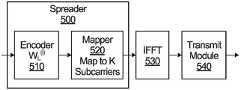
- FIG. 5illustrates a block diagram of a spreader 500 configured for DFT-S-MC-CDMA in accordance with an embodiment of the present disclosure.
- the spreader 500may be for use in encoding and transmitting data from a user device 102 , or from a network node 104 .
- the spreader 500is configured to receive data for transmission and spread the data with a spreading sequence to generate multi-carrier spread data.
- the spreader 500may include an encoder 510 configured to encode binary data to generate a modulated data stream, and a mapper 520 configured to map the modulated data stream onto non-zero subcarrier elements of a spreading sequence.
- the encoder 510is configured to apply the column values of the i th L ⁇ L R-DFT matrix W L (i) to the received data to generate L DFT output values
- the mapper 520is configured to map the L DFT output values onto K subcarriers to generate a spreading sequence of length K.
- the mapping of the L DFT output values onto K subcarriersmust be done such that there is an equal spacing between non-zero subcarrier elements in the spreading sequence.
- the multi-carrier spread data sequencesmay then be transformed into a time domain signal by an inverse fast fourier transform (IFFT) module 530 and transmitted through a wireless medium by a transmit module 540 which may implement additional functions such as pulse shaping and subcarrier modulation.
- IFFTinverse fast fourier transform
- encoder and mapper modules 510 , 520may be implemented as one component in hardware, or in software, or in a combination thereof.
- the modules 510 , 520may be part of the communications interface 208 , 308 or executed by the processor 202 , 302 in the device 102 or network node 104 .
- the mapper 520is configured to map the L DFT output values onto K subcarriers to generate a spreading sequence of length K.
- the size of the DFTi.e., by adjusting L
- the throughput of the devicecan be adjusted, because adjusting L changes the sparsity level of the spreading sequence.
- Uplink (UL) MC-CDMAis non-orthogonal in a frequency selective channel, even when the spreading codes used by UEs are orthogonal.
- LDS-OFDMfurther relaxes this condition of orthogonality by employing partial collision spreading codes.
- a large pool of partial collision sequencescan be designed.
- one or more of the following parameters of the sequence poolmay be configurable:
- any difference between spreading sequences in any of the above dimensionswill change the collision level between the sequences. Examples of spreading sequences that differ in one or more of the above dimensions are discussed below with reference to FIGS. 6 to 8 .
- FIG. 6shows frequency domain spreading sequences 600 A and 600 B having different sparsity levels for two UEs 102 A and 102 B according to an embodiment of the present disclosure.
- Each of the spreading sequences 600 A, 600 Bhas six subcarrier elements.
- spreading sequence 600 Ahas four non-zero subcarrier elements 602 A 1 , 602 A 2 , 602 A 3 , and 602 A 4 on the second through fifth subcarriers
- spreading sequence 600 Bhas two non-zero subcarrier elements 602 B 1 and 602 B 2 on the first and third subcarriers.
- the spreading sequence 600 A for UE 102 Ahas twice the number of non-zero subcarriers as the spreading sequence 600 B for UE 102 B, and hence UE 102 A can potentially have double the throughput of UE 102 B.
- the spreading sequences 600 A and 600 Bboth provide single carrier PAPR, because the spacing between adjacent non-zero subcarrier elements in both spreading sequences is constant, although the equal spacing between the non-zero subcarrier elements 602 A 1 , 602 A 2 , 602 A 3 and 602 A 4 of spreading sequence 600 A is different from the equal spacing between the non-zero subcarrier elements 602 B 1 and 602 B 2 of spreading sequence 600 B.
- the non-zero subcarrier elements 602 A 1 , 602 A 2 , 602 A 3 and 602 A 4are mapped to immediately adjacent subcarriers in spreading sequence 600 A and the non-zero subcarrier elements 602 B 1 and 602 B 2 are mapped to subcarriers that are separated by one intervening subcarrier.
- spreading sequences with different sparsity levelsmay have the same equal spacing between their non-zero subcarrier elements.
- the spreading sequence 600 A for UE 102 Apartially collides with the spreading sequence 600 B for UE 102 B, because the non-zero subcarrier elements 602 A 2 and 60 B 2 overlap on the third subcarrier. Because the collision between the spreading sequences 600 A and 600 B is only partial, a receiver may still be able to receive and decode data spread and transmitted by UEs 102 A and 102 B using the spreading sequences 600 A and 600 B.
- FIG. 7shows frequency domain spreading sequences 700 A, 700 B, 700 C and 700 D having different sparsity patterns for four UEs 102 A, 102 B, 102 C and 102 D according to an embodiment of the present disclosure.
- each of the spreading sequenceshas six subcarrier elements and has the same sparsity level, i.e., each spreading sequence has two non-zero subcarrier elements.
- spreading sequence 700 Ahas non-zero subcarrier elements 702 A 1 and 702 A 2 on the second and third subcarriers
- spreading sequence 700 Bhas non-zero subcarrier elements 702 B 1 and 702 B 2 on the first and third subcarriers
- spreading sequence 700 Chas non-zero subcarrier elements 702 C 1 and 702 C 2 on the first and fifth subcarriers
- spreading sequence 700 Dhas non-zero subcarrier elements 702 D 1 and 702 D 2 on the third and sixth subcarriers.
- the spreading sequences 700 A, 700 B, 700 C and 700 Dprovide single carrier PAPR.
- the spreading sequences 700 A, 700 B, 700 C and 700 D depicted in FIG. 7each have a different spacing between their non-zero subcarrier elements.
- the non-zero subcarrier elements 702 B 1 and 702 B 2 of spreading sequence 700 Bare separated by one intervening null subcarrier element and the non-zero subcarrier elements 702 C 1 and 702 C 2 are separated by three null subcarrier elements.
- the non-zero subcarrier elements 702 B 1 and 702 B 2 of spreading sequence 700 Bare separated by one intervening null subcarrier element and the non-zero subcarrier elements 702 C 1 and 702 C 2 are separated by three null subcarrier elements.
- the spreading sequence 700 A for UE 102 A, the spreading sequence 700 B for UE 102 B, and the spreading sequence 700 D for UE 102 Dpartially collide, because the non-zero subcarrier elements 702 A 2 , 702 B 2 and 702 D 1 overlap on the third subcarrier.
- the spreading sequence 700 B for UE 102 Bpartially collides with the spreading sequence 700 C for UE 102 C, because the non-zero subcarrier elements 702 B 1 and 702 C 1 overlap on the first subcarrier.
- a receivermay still be able to receive and decode data spread and transmitted by UEs 102 A, 102 B, 102 C, and 102 D using the spreading sequences 700 A, 700 B, 700 C and 700 D.
- FIG. 8shows frequency domain and time domain plots of eight spreading sequences 800 A, 801 A, 800 B, 801 B, 800 C, 801 C, 800 D and 801 D having different sparsity patterns and/or time domain pulse offsets for multi-sequence transmission by four UEs 102 A, 102 B, 102 C and 102 D according to an embodiment of the present disclosure.
- Each of the UEs 102 A, 102 B, 102 C and 102 Dis assigned two of the spreading sequences.
- each of the spreading sequenceshas four subcarrier elements and has the same sparsity level, i.e., each spreading sequence has two non-zero subcarrier elements.
- the spreading sequences 800 A and 801 A assigned to UE 102 A and the spreading sequences 800 C and 801 C assigned to UE 102 Cshare a common sparsity pattern with a first non-zero subcarrier element ( 802 A 1 , 803 A 1 , 802 C 1 and 803 C 1 , respectively) on the first subcarrier and a second non-zero subcarrier element ( 802 A 2 , 803 A 2 , 802 C 2 and 803 C 2 , respectively) on the third subcarrier.
- the spreading sequences 800 B and 801 B assigned to UE 102 B and the spreading sequences 800 D and 801 D assigned to UE 102 Dshare a common sparsity pattern that is different from the sparsity pattern shared by the spreading sequences 800 A, 801 A, 800 C and 801 C.
- the spreading sequences 800 B, 801 B, 800 D and 801 Deach have a first non-zero subcarrier element ( 802 B 1 , 803 B 1 , 802 D 1 and 803 D 1 , respectively) on the second subcarrier and a second non-zero subcarrier element ( 802 B 2 , 803 B 2 , 802 D 2 and 803 D 2 , respectively) on the fourth subcarrier.
- the eight spreading sequences 800 A, 801 A, 800 B, 801 B, 800 C, 801 C, 800 D and 801 Dare configured so that each subcarrier has four non-zero subcarrier elements mapped onto it.
- these collisionsare only partial because the non-zero subcarrier element values of the spreading sequences are configured to provide a pulse offset in the time domain.
- the non-zero subcarrier elements of the spreading sequences 800 A, 801 A, 800 C and 801 Cmay be configured with the column values of the two R-DFT matrices W 2 (0) and W 2 (1) described above such that:
- spreading sequence 800 A[1 0 1 0],
- spreading sequence 801 A[1 0 ⁇ 1 0],
- spreading sequence 800 C[1 0 j 0],
- spreading sequence 801 C[1 0 ⁇ j 0].
- the two spreading sequences 800 A and 801 A assigned to UE 102 Ahave a phase rotation relative to one another and also have a phase rotation relative to the two spreading sequences 800 C and 801 C assigned to UE 102 C, which in turn have a phase rotation relative to one another.
- This relative phase rotationproduces time offsets between the time domain pulses 810 A and 811 A for UE 102 A and the time domain pulses 810 C and 811 C for UE 102 C even though the spreading sequences 800 A, 801 A, 800 C and 801 C overlap in the frequency domain.
- the column values of the two R-DFT matrices W 2 (0) and W 2 (1)can be mapped to the non-zero elements of the spreading sequences 800 B, 801 B, 800 C and 801 C such that:
- spreading sequence 800 B[0 1 0 1],
- spreading sequence 801 B[0 1 0 ⁇ 1],
- spreading sequence 800 D[0 1 0 j],
- spreading sequence 801 D[0 1 0 ⁇ j].
- the relative phase rotation between the spreading sequences 800 B, 801 B, 800 D and 801 Dproduces time offsets between the time domain pulses 810 B and 811 B for UE 102 B and the time domain pulses 810 D and 811 D for UE 102 D even though the spreading sequences 800 B, 801 B, 800 D and 801 D overlap in the frequency domain.
- each sparsity patternmay be considered as corresponding to a codebook.
- Each codebookconsists of multiple spreading sequences (or codewords) which are generated from different pulse offsets (phase rotations in the frequency domain) by assigning the non-zero subcarrier elements of the spreading sequences values corresponding to the column values of R-DFT matrices.
- equation (1)results in the following four R-DFT matrices:
- W 2 ( 0 )[ 1 1 1 - 1 ]
- ⁇ W 2 ( 1 )[ 1 1 2 ⁇ / ⁇ 2 + j ⁇ 2 ⁇ / ⁇ 2 - ( 2 ⁇ / ⁇ 2 + j ⁇ 2 ⁇ / ⁇ 2 ) ]
- ⁇ W 2 ( 2 )[ 1 1 j - j ]
- ⁇ W 2 ( 3 )[ 1 1 - 2 ⁇ / ⁇ 2 + j ⁇ 2 ⁇ / ⁇ 2 2 ⁇ / ⁇ 2 - j ⁇ 2 ⁇ / ⁇ 2 ] .
- W 3 ( 0 )[ 1 1 1 1 - 1 ⁇ / ⁇ 2 + j ⁇ 3 ⁇ / ⁇ 2 - 1 ⁇ / ⁇ 2 - j ⁇ 3 ⁇ / ⁇ 2 1 - 1 ⁇ / ⁇ 2 - j ⁇ 3 ⁇ / ⁇ 2 - 1 ⁇ / ⁇ 2 + j ⁇ 3 ⁇ / ⁇ 2 ]
- W 3 ( 1 )[ 1 1 1 1 ⁇ / ⁇ 2 + j ⁇ 3 ⁇ / ⁇ 2 - 1 1 ⁇ / ⁇ 2 - j ⁇ 3 ⁇ / ⁇ 2 - 1 ⁇ / ⁇ 2 + j ⁇ 3 ⁇ / ⁇ 2 1 - 1 ⁇ / ⁇ 2 - j ⁇ 3 ⁇ / ⁇ 2 ] .
- the codewords in a codebookcan be used by a single UE to enhance date rate or used by different UEs to support a greater number of connected UEs.
- a codebook that includes spreading sequences 800 A, 801 A, 800 C and 801 Callows UEs 102 A and 102 C to both be supported on the first and third subcarriers. Assigning each of the UEs 102 A and 102 C two of the spreading sequences can potentially double the data rate of UEs 102 A and 102 C.
- the example spreading sequences shown in FIGS. 4 and 6 to 8include 4 or 6 subcarrier elements. More generally, spreading sequences may include 4 or more subcarrier elements. For example, in some embodiments spreading sequences may include 8 subcarrier elements, 16 subcarrier elements, or even more. Furthermore, different UEs may use spreading sequences of different lengths. For example, some UEs may use spreading sequences with a length of 16 subcarrier elements to support high throughput, and other UEs may use spreading sequences with a length of 8 subcarrier elements.
- One of the applications contemplated for the MC-CDMA techniques disclosed hereinis in uplink random access.
- uplink random accessdifferent user devices 102 can access the same radio resource at the same time.
- data transmitted by a user device 102 in accordance with the MC-CDMA transmission scheme disclosed hereinmay be received and decoded by the network node 104 .
- the network node 104may receive multiple data transmissions from different devices 102 , each of which is transmitting data according to its assigned spreading sequence(s).
- the MC-CDMA transmission scheme disclosed hereinif the network load is light or moderate, the received data may be decoded using a successive interference cancellation (SIC) decoding. If the network load is high, other decoding schemes such as MPA or MMSE may be used.
- SICsuccessive interference cancellation
- a receivermay perform the following functions for signal detection:
- the receiver of the network node 104may first decode the data element on the fifth subcarrier of the signal associated with spreading sequence 700 C because, in this example, no other data elements are transmitted on this subcarrier.
- the data element on the first subcarrier of the signal associated with spreading sequence 700 Cis also known, because the same data element is spread to the two non-zero subcarrier elements 702 C 1 and 702 C 2 of spreading sequence 700 C.
- the signal associated with spreading sequence 700 Balso has a data element on the first subcarrier. Because the data element on the first subcarrier of the signal associated with spreading sequence 700 C has been determined, its interference effect can be removed.
- the network node 104may apply a combination of MMSE and SIC decoding in order to receive and decode partially collided data sequences.
- an MMSE decodermay be used to decode the data element on the first subcarrier of the signal associated with spreading sequence 700 C which collides with the data element on the first subcarrier of the signal associated with spreading sequence 700 B. That result may be combined with the result for the data element on the fifth subcarrier of the signal associated with spreading sequence 700 C (which is collision free) to improve the decoder's capability.
- MMSE decodingmay be applied to the signals having the least collisions with other user signals. With the use of SIC and the interlaced structure of spreading sequences due to the partial collision sequence design, each successful decoding of one signal may simplify the decoding of the other undecoded signals.
- MMSE with SICcan be implemented in a system with multiple receive antennas.
- the systemoperates as a Multiple-User Multiple-Input and Multiple-Output (MU-MIMO)/DFT-S-OFDM system, with DFT-spread signals being sparsely mapped to an access resource block, and thus randomizing the inter-user collision.
- MU-MIMOMultiple-User Multiple-Input and Multiple-Output
- DFT-spread signalsbeing sparsely mapped to an access resource block, and thus randomizing the inter-user collision.
Landscapes
- Engineering & Computer Science (AREA)
- Signal Processing (AREA)
- Computer Networks & Wireless Communication (AREA)
- Physics & Mathematics (AREA)
- Discrete Mathematics (AREA)
- General Physics & Mathematics (AREA)
- Mathematical Physics (AREA)
- Mobile Radio Communication Systems (AREA)
Abstract
Description
- Limited throughput: this is because subcarrier index modulation is inefficient from a spectral efficiency point of view, especially when the number of subcarriers is large, and this is why the number of subcarriers is usually limited to 4; and
- Lost spectral efficiency when SNR is high: this is because although the QAM order can be increased on the active subcarrier to carry more information, subcarrier index modulation is unable to take advantage of this high SNR, because it can only increase the modulation order on one active subcarrier.
- Each communication device, such as mobile User Equipment (UE), can use multiple spreading sequences, while still having a low PAPR;
- The spreading sequences can have a sparse or low density of non-zero subcarrier elements (e.g., 50% or fewer non-zero subcarrier elements), depending on throughput needs;
- A pool of partial collision codebooks (in terms of both codewords/spreading sequences and signaling pulse) can be used to mitigate the effect of device codebook collision and increase the number of random access devices.
where i is the rotation index, 0≤i≤N/L−1, wk,n(i)is the “k th row/n th column” element of WL(i), L is the size of the R-DFT matrix, and (N/L−1) defines the total number of rotation indexes. For example, with L=2 and N=4, equation (1) results in:
where W2(0), i.e., i=0, is the conventional DFT matrix and W2(1), i.e., i=1, is a rotated DFT matrix. Here, the rotation matrix Q that transforms W2(0)to W2(1), i.e. Q×W2(0)=
- Sparsity level—UEs with different throughput may use spreading sequences of different sparsity level, which corresponds to repetition level in the time domain;
- Sparsity pattern (frequency domain)—manifested as non-zero subcarrier element collision in the frequency domain; and
- Pulse offset (time domain)—manifested as pulse offsets in the time domain.
- 1) On subcarriers with collision, an MMSE receiver or an MPA receiver may be used;
- 2) IDFT de-spreading, QAM de-mapping, and FEC decoding may then be used to decode transmissions;
- 3) SIC may be used to remove successfully decoded transmissions, and then steps 1) and 2) are repeated for remaining transmissions.
Claims (28)
Priority Applications (8)
| Application Number | Priority Date | Filing Date | Title |
|---|---|---|---|
| US15/164,388US10917167B2 (en) | 2015-05-29 | 2016-05-25 | MC-CDMA with low peak-to-average power ratio multi-carrier waveform |
| CN201911220080.0ACN111131115A (en) | 2015-05-29 | 2016-05-26 | MC-CDMA with Low Peak-to-Average Power Ratio Multi-Carrier Waveforms |
| CN201680021958.6ACN107534638B (en) | 2015-05-29 | 2016-05-26 | MC-CDMA with low peak-to-average power ratio multi-carrier waveform |
| EP19191740.0AEP3598669A1 (en) | 2015-05-29 | 2016-05-26 | Mc-cdma with low peak-to-average power ratio multi-carrier waveform |
| PCT/CN2016/083487WO2016192576A1 (en) | 2015-05-29 | 2016-05-26 | Mc-cdma with low peak-to-average power ratio multi-carrier waveform |
| JP2017561839AJP2018519731A (en) | 2015-05-29 | 2016-05-26 | MC-CDMA with low peak-to-average power ratio multi-carrier waveform |
| EP16802499.0AEP3292670B1 (en) | 2015-05-29 | 2016-05-26 | Mc-cdma with low peak-to-average power ratio multi-carrier waveform |
| KR1020177037137AKR102080155B1 (en) | 2015-05-29 | 2016-05-26 | MC-CDMA with low peak-to-average power ratio multicarrier waveform |
Applications Claiming Priority (3)
| Application Number | Priority Date | Filing Date | Title |
|---|---|---|---|
| US201562168437P | 2015-05-29 | 2015-05-29 | |
| US201562262142P | 2015-12-02 | 2015-12-02 | |
| US15/164,388US10917167B2 (en) | 2015-05-29 | 2016-05-25 | MC-CDMA with low peak-to-average power ratio multi-carrier waveform |
Publications (2)
| Publication Number | Publication Date |
|---|---|
| US20160352478A1 US20160352478A1 (en) | 2016-12-01 |
| US10917167B2true US10917167B2 (en) | 2021-02-09 |
Family
ID=57399298
Family Applications (1)
| Application Number | Title | Priority Date | Filing Date |
|---|---|---|---|
| US15/164,388ActiveUS10917167B2 (en) | 2015-05-29 | 2016-05-25 | MC-CDMA with low peak-to-average power ratio multi-carrier waveform |
Country Status (6)
| Country | Link |
|---|---|
| US (1) | US10917167B2 (en) |
| EP (2) | EP3292670B1 (en) |
| JP (1) | JP2018519731A (en) |
| KR (1) | KR102080155B1 (en) |
| CN (2) | CN111131115A (en) |
| WO (1) | WO2016192576A1 (en) |
Cited By (10)
| Publication number | Priority date | Publication date | Assignee | Title |
|---|---|---|---|---|
| US11075786B1 (en) | 2004-08-02 | 2021-07-27 | Genghiscomm Holdings, LLC | Multicarrier sub-layer for direct sequence channel and multiple-access coding |
| US11184037B1 (en) | 2004-08-02 | 2021-11-23 | Genghiscomm Holdings, LLC | Demodulating and decoding carrier interferometry signals |
| US11196603B2 (en) | 2017-06-30 | 2021-12-07 | Genghiscomm Holdings, LLC | Efficient synthesis and analysis of OFDM and MIMO-OFDM signals |
| US11381438B2 (en) | 2018-09-29 | 2022-07-05 | Zte Corporation | Multiple access schemes with interference mitigation |
| US11381285B1 (en) | 2004-08-02 | 2022-07-05 | Genghiscomm Holdings, LLC | Transmit pre-coding |
| US11424792B2 (en) | 2001-04-26 | 2022-08-23 | Genghiscomm Holdings, LLC | Coordinated multipoint systems |
| US11700162B2 (en) | 2017-05-25 | 2023-07-11 | Tybalt, Llc | Peak-to-average-power reduction for OFDM multiple access |
| US11791953B2 (en) | 2019-05-26 | 2023-10-17 | Tybalt, Llc | Non-orthogonal multiple access |
| US12206535B1 (en) | 2018-06-17 | 2025-01-21 | Tybalt, Llc | Artificial neural networks in wireless communication systems |
| US12224860B1 (en) | 2014-01-30 | 2025-02-11 | Genghiscomm Holdings, LLC | Linear coding in decentralized networks |
Families Citing this family (10)
| Publication number | Priority date | Publication date | Assignee | Title |
|---|---|---|---|---|
| CN108476114B (en)* | 2015-12-08 | 2021-04-09 | 瑞典爱立信有限公司 | Method of interleaving mode selection for low CM/PAPR transmission |
| EP3375213B1 (en)* | 2017-02-03 | 2022-06-15 | Telefonaktiebolaget LM Ericsson (publ) | Method and device for performing uplink transmission |
| US11456813B2 (en)* | 2018-02-13 | 2022-09-27 | Qualcomm Incorporated | PAPR and inter-cell interference reduction |
| US10498558B1 (en)* | 2018-05-11 | 2019-12-03 | Mitsubishi Electric Research Laboratories, Inc. | Symbol detection in shared wireless channel |
| WO2019242006A1 (en)* | 2018-06-22 | 2019-12-26 | Nokia Shanghai Bell Co., Ltd. | Modulated symbol spreading |
| CN110971556B (en)* | 2018-09-28 | 2022-04-12 | 大唐移动通信设备有限公司 | Signal processing method of wireless communication system, terminal equipment and network equipment |
| US11133969B2 (en)* | 2019-09-04 | 2021-09-28 | Huawei Technologies Co., Ltd. | Low peak to average power ratio single tone sparse transmission |
| CN111294082B (en)* | 2020-02-10 | 2021-04-13 | 西安电子科技大学 | A spread spectrum-based parallel transmission OFDM communication method and system |
| US11474197B2 (en)* | 2020-03-13 | 2022-10-18 | Huawei Technologies Co., Ltd. | Method and apparatus for communication and sensing in wireless communication network operating in half-duplex mode |
| US11070245B1 (en)* | 2020-08-21 | 2021-07-20 | Huawei Technologies Co., Ltd. | System and method for single-carrier multiple access transmission |
Citations (34)
| Publication number | Priority date | Publication date | Assignee | Title |
|---|---|---|---|---|
| US20030100278A1 (en)* | 2001-10-06 | 2003-05-29 | Devaney Patrick Owen | System and method for reduced deviation time domain FM/PM discriminator to achieve a reduced bandwidth frequency or phase modulation communications channels |
| US20030112744A1 (en)* | 2001-12-13 | 2003-06-19 | Baum Kevin Lynn | Method and system of operation for a variable transmission mode multi-carrier communication system |
| US20040252631A1 (en)* | 2003-06-16 | 2004-12-16 | Young-Seo Park | System and method for reducing adjacent channel interference (ACI) in a multicarrier modulation system |
| US20050111425A1 (en)* | 2003-09-01 | 2005-05-26 | Mitsubishi Denki Kabushiki Kaisha | Method of dynamically assigning spreading sequences to users of a multi carrier transmission network |
| US20050250460A1 (en)* | 2004-05-07 | 2005-11-10 | Samsung Electronics Co., Ltd. | Apparatus and method for generating pseudo-replica signals in a CDMA communication system |
| US20070081604A1 (en) | 2005-10-07 | 2007-04-12 | Samsung Electronics Co., Ltd. | Apparatus and method for reduced peak-to-average-power ratio in a wireless network |
| US20070291635A1 (en)* | 2006-06-15 | 2007-12-20 | Motorola, Inc. | Method and apparatus for switching between ofdm communication modes |
| US20080043814A1 (en) | 2006-08-16 | 2008-02-21 | Harris Corporation, Corporation Of The State Of Delaware | Method of Communicating and Associated Transmitter Using Coded Orthogonal Frequency Division Multiplexing (COFDM) |
| CN101272372A (en) | 2008-03-31 | 2008-09-24 | 北京北方烽火科技有限公司 | OFDM automatic closed-loop transmitting scattered pilot insertion control method |
| WO2008153350A1 (en) | 2007-06-14 | 2008-12-18 | Lg Electronics Inc. | Method of transmitting control signals in wireless communication system |
| US20090022207A1 (en) | 2002-08-12 | 2009-01-22 | Alereon, Inc. | Method for Generating Communication Signal Sequences Having Desirable Correlation Properties and System for Using Same |
| US20090125260A1 (en)* | 2007-11-08 | 2009-05-14 | Siemens Aktiengesellschaft | Method and device for performing a frequency analysis of an ac voltage signal, in particular on a power grid |
| CN101692664A (en) | 2009-10-13 | 2010-04-07 | 清华大学 | Multi-carrier wireless transmission method for adopting discontinuous carrier wave interference code |
| US20100165829A1 (en) | 2008-12-31 | 2010-07-01 | Qualcomm Incorporated | Methods and systems for papr reduction in sc-fdma systems |
| US20100254484A1 (en) | 2007-11-26 | 2010-10-07 | Sharp Kabushiki Kaisha | Wireless communication system, wireless transmission device, wireless communication method, and program |
| US20110110246A1 (en)* | 2009-05-04 | 2011-05-12 | Qualcomm Incorporated | Transmission of feedback information for multi-carrier operation |
| US20110116455A1 (en)* | 2009-05-04 | 2011-05-19 | Qualcomm Incorporated | Transmission of feedback information for data transmissions on multiple carriers |
| US20120127952A1 (en)* | 2009-06-19 | 2012-05-24 | Panasonic Corporation | Method and device for superimposing reference signal and data based on space division multiple access |
| US20120155422A1 (en)* | 2010-12-20 | 2012-06-21 | Telefonaktiebolaget Lm Ericsson (Publ) | Mobility-based radio resource assignment methods, systems and devices |
| US20120230371A1 (en)* | 2011-03-07 | 2012-09-13 | A.P.M. Automation Solutions Ltd. | Variable length ranging and direction-finiding signals constructed from bandlimited kernels and sparse spreading sequences |
| WO2012140847A1 (en) | 2011-04-15 | 2012-10-18 | パナソニック株式会社 | Transmitter apparatus, receiver apparatus, signal generating method and quality estimating method |
| US20130216231A1 (en) | 2012-02-16 | 2013-08-22 | Qi Yang | Optical communication system, transmission apparatus and reception apparatus, and transmission method and reception method |
| CN103346993A (en) | 2013-06-25 | 2013-10-09 | 电子科技大学 | Wide-interval carrier wave mapping method used for multi-carrier-wave frequency-shift keying system |
| WO2013163955A1 (en) | 2012-05-04 | 2013-11-07 | 电信科学技术研究院 | Method, system and apparatus for uplink transmission |
| US20140140360A1 (en)* | 2012-11-16 | 2014-05-22 | Futurewei Technologies, Inc. | Systems and Methods for Sparse Code Multiple Access |
| US20140169409A1 (en) | 2012-12-14 | 2014-06-19 | Futurewei Technologies, Inc. | Systems and Methods for Open-loop Spatial Multiplexing Schemes for Radio Access Virtualization |
| WO2014090189A1 (en) | 2012-12-14 | 2014-06-19 | Huawei Technologies Co., Ltd. | System and method for open-loop mimo communications in a scma communications system |
| US20140185654A1 (en)* | 2005-03-24 | 2014-07-03 | Guodong Zhang | Orthogonal freequency division multiplexing-code division multiple access system |
| WO2014144758A1 (en) | 2013-03-15 | 2014-09-18 | Huawei Technologies Co., Ltd. | Low complexity receiver and method for low density signature modulation |
| US20140293987A1 (en) | 2013-03-28 | 2014-10-02 | Futurewei Technologies, Inc. | System and Method for Generalized Multi-Carrier Frequency Division Multiplexing |
| CN104320234A (en) | 2008-08-05 | 2015-01-28 | Lg电子株式会社 | Radio access method for reduced PAPR |
| CN104509152A (en) | 2012-08-03 | 2015-04-08 | 高通股份有限公司 | Communicate with enhanced new carrier types to save power |
| US20160080060A1 (en)* | 2014-09-16 | 2016-03-17 | Mediatek Inc. | Channel State Information Collection for Wireless Communication System with Beamforming |
| US20160254889A1 (en)* | 2002-05-14 | 2016-09-01 | Genghiscomm Holdings, LLC | Spreading and Precoding in OFDM |
- 2016
- 2016-05-25USUS15/164,388patent/US10917167B2/enactiveActive
- 2016-05-26CNCN201911220080.0Apatent/CN111131115A/ennot_activeWithdrawn
- 2016-05-26WOPCT/CN2016/083487patent/WO2016192576A1/ennot_activeCeased
- 2016-05-26EPEP16802499.0Apatent/EP3292670B1/enactiveActive
- 2016-05-26CNCN201680021958.6Apatent/CN107534638B/enactiveActive
- 2016-05-26JPJP2017561839Apatent/JP2018519731A/ennot_activeCeased
- 2016-05-26KRKR1020177037137Apatent/KR102080155B1/ennot_activeExpired - Fee Related
- 2016-05-26EPEP19191740.0Apatent/EP3598669A1/ennot_activeWithdrawn
Patent Citations (41)
| Publication number | Priority date | Publication date | Assignee | Title |
|---|---|---|---|---|
| US20030100278A1 (en)* | 2001-10-06 | 2003-05-29 | Devaney Patrick Owen | System and method for reduced deviation time domain FM/PM discriminator to achieve a reduced bandwidth frequency or phase modulation communications channels |
| US20030112744A1 (en)* | 2001-12-13 | 2003-06-19 | Baum Kevin Lynn | Method and system of operation for a variable transmission mode multi-carrier communication system |
| US20160254889A1 (en)* | 2002-05-14 | 2016-09-01 | Genghiscomm Holdings, LLC | Spreading and Precoding in OFDM |
| US20090022207A1 (en) | 2002-08-12 | 2009-01-22 | Alereon, Inc. | Method for Generating Communication Signal Sequences Having Desirable Correlation Properties and System for Using Same |
| US20040252631A1 (en)* | 2003-06-16 | 2004-12-16 | Young-Seo Park | System and method for reducing adjacent channel interference (ACI) in a multicarrier modulation system |
| US20050111425A1 (en)* | 2003-09-01 | 2005-05-26 | Mitsubishi Denki Kabushiki Kaisha | Method of dynamically assigning spreading sequences to users of a multi carrier transmission network |
| US20050250460A1 (en)* | 2004-05-07 | 2005-11-10 | Samsung Electronics Co., Ltd. | Apparatus and method for generating pseudo-replica signals in a CDMA communication system |
| US20140185654A1 (en)* | 2005-03-24 | 2014-07-03 | Guodong Zhang | Orthogonal freequency division multiplexing-code division multiple access system |
| US20070081604A1 (en) | 2005-10-07 | 2007-04-12 | Samsung Electronics Co., Ltd. | Apparatus and method for reduced peak-to-average-power ratio in a wireless network |
| US20070291635A1 (en)* | 2006-06-15 | 2007-12-20 | Motorola, Inc. | Method and apparatus for switching between ofdm communication modes |
| JP2010501146A (en) | 2006-08-16 | 2010-01-14 | ハリス コーポレイション | Communication method using coded orthogonal frequency division multiplexing (COFDM) and related transmitter |
| US20080043814A1 (en) | 2006-08-16 | 2008-02-21 | Harris Corporation, Corporation Of The State Of Delaware | Method of Communicating and Associated Transmitter Using Coded Orthogonal Frequency Division Multiplexing (COFDM) |
| US7860147B2 (en) | 2006-08-16 | 2010-12-28 | Harris Corporation | Method of communicating and associated transmitter using coded orthogonal frequency division multiplexing (COFDM) |
| JP2010519879A (en) | 2007-06-14 | 2010-06-03 | エルジー エレクトロニクス インコーポレイティド | Method for transmitting control signals in a wireless communication system |
| WO2008153350A1 (en) | 2007-06-14 | 2008-12-18 | Lg Electronics Inc. | Method of transmitting control signals in wireless communication system |
| US20140376524A1 (en) | 2007-06-14 | 2014-12-25 | Lg Electronics Inc. | Method of transmitting control signals in wireless communication system |
| US20090125260A1 (en)* | 2007-11-08 | 2009-05-14 | Siemens Aktiengesellschaft | Method and device for performing a frequency analysis of an ac voltage signal, in particular on a power grid |
| US20100254484A1 (en) | 2007-11-26 | 2010-10-07 | Sharp Kabushiki Kaisha | Wireless communication system, wireless transmission device, wireless communication method, and program |
| JP2014140256A (en) | 2007-11-26 | 2014-07-31 | Sharp Corp | Terminal device, base station device, radio communication method, and program |
| CN101272372A (en) | 2008-03-31 | 2008-09-24 | 北京北方烽火科技有限公司 | OFDM automatic closed-loop transmitting scattered pilot insertion control method |
| US20150195840A1 (en) | 2008-08-05 | 2015-07-09 | Lg Electronics Inc. | Radio access method for reduced papr |
| CN104320234A (en) | 2008-08-05 | 2015-01-28 | Lg电子株式会社 | Radio access method for reduced PAPR |
| CN102273158A (en) | 2008-12-31 | 2011-12-07 | 高通股份有限公司 | Methods and systems for papr reduction in sc-fdma systems |
| US20100165829A1 (en) | 2008-12-31 | 2010-07-01 | Qualcomm Incorporated | Methods and systems for papr reduction in sc-fdma systems |
| US20110110246A1 (en)* | 2009-05-04 | 2011-05-12 | Qualcomm Incorporated | Transmission of feedback information for multi-carrier operation |
| US20110116455A1 (en)* | 2009-05-04 | 2011-05-19 | Qualcomm Incorporated | Transmission of feedback information for data transmissions on multiple carriers |
| US20120127952A1 (en)* | 2009-06-19 | 2012-05-24 | Panasonic Corporation | Method and device for superimposing reference signal and data based on space division multiple access |
| CN101692664A (en) | 2009-10-13 | 2010-04-07 | 清华大学 | Multi-carrier wireless transmission method for adopting discontinuous carrier wave interference code |
| US20120155422A1 (en)* | 2010-12-20 | 2012-06-21 | Telefonaktiebolaget Lm Ericsson (Publ) | Mobility-based radio resource assignment methods, systems and devices |
| US20120230371A1 (en)* | 2011-03-07 | 2012-09-13 | A.P.M. Automation Solutions Ltd. | Variable length ranging and direction-finiding signals constructed from bandlimited kernels and sparse spreading sequences |
| WO2012140847A1 (en) | 2011-04-15 | 2012-10-18 | パナソニック株式会社 | Transmitter apparatus, receiver apparatus, signal generating method and quality estimating method |
| US20130216231A1 (en) | 2012-02-16 | 2013-08-22 | Qi Yang | Optical communication system, transmission apparatus and reception apparatus, and transmission method and reception method |
| WO2013163955A1 (en) | 2012-05-04 | 2013-11-07 | 电信科学技术研究院 | Method, system and apparatus for uplink transmission |
| CN104509152A (en) | 2012-08-03 | 2015-04-08 | 高通股份有限公司 | Communicate with enhanced new carrier types to save power |
| US20140140360A1 (en)* | 2012-11-16 | 2014-05-22 | Futurewei Technologies, Inc. | Systems and Methods for Sparse Code Multiple Access |
| US20140169409A1 (en) | 2012-12-14 | 2014-06-19 | Futurewei Technologies, Inc. | Systems and Methods for Open-loop Spatial Multiplexing Schemes for Radio Access Virtualization |
| WO2014090189A1 (en) | 2012-12-14 | 2014-06-19 | Huawei Technologies Co., Ltd. | System and method for open-loop mimo communications in a scma communications system |
| WO2014144758A1 (en) | 2013-03-15 | 2014-09-18 | Huawei Technologies Co., Ltd. | Low complexity receiver and method for low density signature modulation |
| US20140293987A1 (en) | 2013-03-28 | 2014-10-02 | Futurewei Technologies, Inc. | System and Method for Generalized Multi-Carrier Frequency Division Multiplexing |
| CN103346993A (en) | 2013-06-25 | 2013-10-09 | 电子科技大学 | Wide-interval carrier wave mapping method used for multi-carrier-wave frequency-shift keying system |
| US20160080060A1 (en)* | 2014-09-16 | 2016-03-17 | Mediatek Inc. | Channel State Information Collection for Wireless Communication System with Beamforming |
Non-Patent Citations (5)
| Title |
|---|
| Irfan, Mohammad et al., SubCarrier Index-QAM, A New Hybrid Modulation Scheme for OFDM, The Institute of Industrial Applications Engineers, Japan, Mar. 2015, pp. 74-77. |
| Irfan, Mohammad et al., SubCarrier Index—QAM, A New Hybrid Modulation Scheme for OFDM, The Institute of Industrial Applications Engineers, Japan, Mar. 2015, pp. 74-77. |
| R.Hoshyar et al, "LDS-OFDM an efficient multiple access technique," 2010 IEEE 71st Vehicular Technology Conference, May 16-19, 2010, 5 pages. |
| Xu Yingqi,"Research on Peak-to-Average Power Ratio in MC-CDMA System", Xidian University, Jan. 2010, total 10 pages. |
| Yang Dongkai et al.,"Linear Multi-user Detection Based on the Bridge Function for MC-CDMA Systems", Journal of Telemetry, Tracking and Command, vol. 30, No. 2, Mar. 2009, total 7 pages. |
Cited By (21)
| Publication number | Priority date | Publication date | Assignee | Title |
|---|---|---|---|---|
| US11424792B2 (en) | 2001-04-26 | 2022-08-23 | Genghiscomm Holdings, LLC | Coordinated multipoint systems |
| US11646929B1 (en) | 2004-08-02 | 2023-05-09 | Genghiscomm Holdings, LLC | Spreading and precoding in OFDM |
| US11784686B2 (en) | 2004-08-02 | 2023-10-10 | Genghiscomm Holdings, LLC | Carrier interferometry transmitter |
| US11252005B1 (en) | 2004-08-02 | 2022-02-15 | Genghiscomm Holdings, LLC | Spreading and precoding in OFDM |
| US11804882B1 (en) | 2004-08-02 | 2023-10-31 | Genghiscomm Holdings, LLC | Single carrier frequency division multiple access baseband signal generation |
| US11381285B1 (en) | 2004-08-02 | 2022-07-05 | Genghiscomm Holdings, LLC | Transmit pre-coding |
| US11184037B1 (en) | 2004-08-02 | 2021-11-23 | Genghiscomm Holdings, LLC | Demodulating and decoding carrier interferometry signals |
| US11431386B1 (en) | 2004-08-02 | 2022-08-30 | Genghiscomm Holdings, LLC | Transmit pre-coding |
| US12095529B2 (en) | 2004-08-02 | 2024-09-17 | Genghiscomm Holdings, LLC | Spread-OFDM receiver |
| US11075786B1 (en) | 2004-08-02 | 2021-07-27 | Genghiscomm Holdings, LLC | Multicarrier sub-layer for direct sequence channel and multiple-access coding |
| US11575555B2 (en) | 2004-08-02 | 2023-02-07 | Genghiscomm Holdings, LLC | Carrier interferometry transmitter |
| US11671299B1 (en) | 2004-08-02 | 2023-06-06 | Genghiscomm Holdings, LLC | Wireless communications using flexible channel bandwidth |
| US12224860B1 (en) | 2014-01-30 | 2025-02-11 | Genghiscomm Holdings, LLC | Linear coding in decentralized networks |
| US12395268B1 (en) | 2014-01-30 | 2025-08-19 | Genghiscomm Holdings, LLC | Linear network coding in communication networks |
| US11700162B2 (en) | 2017-05-25 | 2023-07-11 | Tybalt, Llc | Peak-to-average-power reduction for OFDM multiple access |
| US11894965B2 (en) | 2017-05-25 | 2024-02-06 | Tybalt, Llc | Efficient synthesis and analysis of OFDM and MIMO-OFDM signals |
| US11196603B2 (en) | 2017-06-30 | 2021-12-07 | Genghiscomm Holdings, LLC | Efficient synthesis and analysis of OFDM and MIMO-OFDM signals |
| US11570029B2 (en) | 2017-06-30 | 2023-01-31 | Tybalt Llc | Efficient synthesis and analysis of OFDM and MIMO-OFDM signals |
| US12206535B1 (en) | 2018-06-17 | 2025-01-21 | Tybalt, Llc | Artificial neural networks in wireless communication systems |
| US11381438B2 (en) | 2018-09-29 | 2022-07-05 | Zte Corporation | Multiple access schemes with interference mitigation |
| US11791953B2 (en) | 2019-05-26 | 2023-10-17 | Tybalt, Llc | Non-orthogonal multiple access |
Also Published As
| Publication number | Publication date |
|---|---|
| US20160352478A1 (en) | 2016-12-01 |
| KR20180011805A (en) | 2018-02-02 |
| CN107534638A (en) | 2018-01-02 |
| CN107534638B (en) | 2019-12-13 |
| KR102080155B1 (en) | 2020-02-21 |
| JP2018519731A (en) | 2018-07-19 |
| EP3292670B1 (en) | 2019-09-11 |
| WO2016192576A1 (en) | 2016-12-08 |
| EP3598669A1 (en) | 2020-01-22 |
| EP3292670A4 (en) | 2018-06-20 |
| EP3292670A1 (en) | 2018-03-14 |
| CN111131115A (en) | 2020-05-08 |
Similar Documents
| Publication | Publication Date | Title |
|---|---|---|
| US10917167B2 (en) | MC-CDMA with low peak-to-average power ratio multi-carrier waveform | |
| US11695507B2 (en) | Apparatus and method for in multiple access in wireless communication | |
| EP3198821B1 (en) | System and method for low peak to average power ratio multiple access communications | |
| EP3172857B1 (en) | System and method for generating waveforms and utilization thereof | |
| EP3289689B1 (en) | Method and system for low data rate transmission | |
| US11456813B2 (en) | PAPR and inter-cell interference reduction | |
| WO2020242898A1 (en) | Non-orthogonal multiple access | |
| KR20190050822A (en) | Methods for Multiple Access Transmission | |
| CN108123903B (en) | Signal processing method and apparatus in communication system | |
| US10624039B2 (en) | System and method for power offset adjustments for downlink communications | |
| KR102542702B1 (en) | Methods and apparatus of repeated transmission for multicarrier wireless communication systems | |
| US20190200378A1 (en) | Operation method of communication node for uplink transmission in communication network | |
| US11533211B2 (en) | Modulation scheme in a wireless communication system | |
| JP6495464B2 (en) | System and method for transmission symbol arrangement for reducing mutual interference | |
| WO2022037133A1 (en) | System and method for single-carrier multiple-access transmission | |
| EP3427458B1 (en) | Systems and methods for spreading and co-orthogonal multi-stream spreading | |
| JP6027637B2 (en) | Antenna port mapping method and apparatus for demodulated reference signal | |
| US10715285B2 (en) | Systems and methods for partial collision multiple access |
Legal Events
| Date | Code | Title | Description |
|---|---|---|---|
| AS | Assignment | Owner name:HUAWEI TECHNOLOGIES CO., LTD., CHINA Free format text:ASSIGNMENT OF ASSIGNORS INTEREST;ASSIGNORS:JIA, MING;MA, JIANGLEI;REEL/FRAME:038897/0401 Effective date:20160603 | |
| STPP | Information on status: patent application and granting procedure in general | Free format text:NON FINAL ACTION MAILED | |
| STPP | Information on status: patent application and granting procedure in general | Free format text:FINAL REJECTION MAILED | |
| STPP | Information on status: patent application and granting procedure in general | Free format text:DOCKETED NEW CASE - READY FOR EXAMINATION | |
| STPP | Information on status: patent application and granting procedure in general | Free format text:NON FINAL ACTION MAILED | |
| STPP | Information on status: patent application and granting procedure in general | Free format text:RESPONSE TO NON-FINAL OFFICE ACTION ENTERED AND FORWARDED TO EXAMINER | |
| STPP | Information on status: patent application and granting procedure in general | Free format text:NOTICE OF ALLOWANCE MAILED -- APPLICATION RECEIVED IN OFFICE OF PUBLICATIONS | |
| STPP | Information on status: patent application and granting procedure in general | Free format text:PUBLICATIONS -- ISSUE FEE PAYMENT RECEIVED | |
| STPP | Information on status: patent application and granting procedure in general | Free format text:AWAITING TC RESP, ISSUE FEE PAYMENT VERIFIED | |
| STCF | Information on status: patent grant | Free format text:PATENTED CASE | |
| MAFP | Maintenance fee payment | Free format text:PAYMENT OF MAINTENANCE FEE, 4TH YEAR, LARGE ENTITY (ORIGINAL EVENT CODE: M1551); ENTITY STATUS OF PATENT OWNER: LARGE ENTITY Year of fee payment:4 |