US10917038B2 - Pneumatic actuator system and method - Google Patents
Pneumatic actuator system and methodDownload PDFInfo
- Publication number
- US10917038B2 US10917038B2US15/955,044US201815955044AUS10917038B2US 10917038 B2US10917038 B2US 10917038B2US 201815955044 AUS201815955044 AUS 201815955044AUS 10917038 B2US10917038 B2US 10917038B2
- Authority
- US
- United States
- Prior art keywords
- hub
- bellows
- actuator
- washers
- flexure
- Prior art date
- Legal status (The legal status is an assumption and is not a legal conclusion. Google has not performed a legal analysis and makes no representation as to the accuracy of the status listed.)
- Expired - Fee Related, expires
Links
Images


Classifications
- H—ELECTRICITY
- H02—GENERATION; CONVERSION OR DISTRIBUTION OF ELECTRIC POWER
- H02S—GENERATION OF ELECTRIC POWER BY CONVERSION OF INFRARED RADIATION, VISIBLE LIGHT OR ULTRAVIOLET LIGHT, e.g. USING PHOTOVOLTAIC [PV] MODULES
- H02S20/00—Supporting structures for PV modules
- H02S20/30—Supporting structures being movable or adjustable, e.g. for angle adjustment
- H02S20/32—Supporting structures being movable or adjustable, e.g. for angle adjustment specially adapted for solar tracking
- B—PERFORMING OPERATIONS; TRANSPORTING
- B25—HAND TOOLS; PORTABLE POWER-DRIVEN TOOLS; MANIPULATORS
- B25J—MANIPULATORS; CHAMBERS PROVIDED WITH MANIPULATION DEVICES
- B25J9/00—Programme-controlled manipulators
- B25J9/10—Programme-controlled manipulators characterised by positioning means for manipulator elements
- B25J9/14—Programme-controlled manipulators characterised by positioning means for manipulator elements fluid
- B25J9/142—Programme-controlled manipulators characterised by positioning means for manipulator elements fluid comprising inflatable bodies
- F—MECHANICAL ENGINEERING; LIGHTING; HEATING; WEAPONS; BLASTING
- F15—FLUID-PRESSURE ACTUATORS; HYDRAULICS OR PNEUMATICS IN GENERAL
- F15B—SYSTEMS ACTING BY MEANS OF FLUIDS IN GENERAL; FLUID-PRESSURE ACTUATORS, e.g. SERVOMOTORS; DETAILS OF FLUID-PRESSURE SYSTEMS, NOT OTHERWISE PROVIDED FOR
- F15B15/00—Fluid-actuated devices for displacing a member from one position to another; Gearing associated therewith
- F15B15/08—Characterised by the construction of the motor unit
- F15B15/10—Characterised by the construction of the motor unit the motor being of diaphragm type
- F—MECHANICAL ENGINEERING; LIGHTING; HEATING; WEAPONS; BLASTING
- F24—HEATING; RANGES; VENTILATING
- F24S—SOLAR HEAT COLLECTORS; SOLAR HEAT SYSTEMS
- F24S30/00—Arrangements for moving or orienting solar heat collector modules
- F24S30/40—Arrangements for moving or orienting solar heat collector modules for rotary movement
- F24S30/42—Arrangements for moving or orienting solar heat collector modules for rotary movement with only one rotation axis
- F24S30/425—Horizontal axis
- F—MECHANICAL ENGINEERING; LIGHTING; HEATING; WEAPONS; BLASTING
- F24—HEATING; RANGES; VENTILATING
- F24S—SOLAR HEAT COLLECTORS; SOLAR HEAT SYSTEMS
- F24S50/00—Arrangements for controlling solar heat collectors
- F24S50/20—Arrangements for controlling solar heat collectors for tracking
- H01L31/042—
- H—ELECTRICITY
- H02—GENERATION; CONVERSION OR DISTRIBUTION OF ELECTRIC POWER
- H02S—GENERATION OF ELECTRIC POWER BY CONVERSION OF INFRARED RADIATION, VISIBLE LIGHT OR ULTRAVIOLET LIGHT, e.g. USING PHOTOVOLTAIC [PV] MODULES
- H02S20/00—Supporting structures for PV modules
- H02S20/10—Supporting structures directly fixed to the ground
- H—ELECTRICITY
- H10—SEMICONDUCTOR DEVICES; ELECTRIC SOLID-STATE DEVICES NOT OTHERWISE PROVIDED FOR
- H10F—INORGANIC SEMICONDUCTOR DEVICES SENSITIVE TO INFRARED RADIATION, LIGHT, ELECTROMAGNETIC RADIATION OF SHORTER WAVELENGTH OR CORPUSCULAR RADIATION
- H10F19/00—Integrated devices, or assemblies of multiple devices, comprising at least one photovoltaic cell covered by group H10F10/00, e.g. photovoltaic modules
- F—MECHANICAL ENGINEERING; LIGHTING; HEATING; WEAPONS; BLASTING
- F15—FLUID-PRESSURE ACTUATORS; HYDRAULICS OR PNEUMATICS IN GENERAL
- F15B—SYSTEMS ACTING BY MEANS OF FLUIDS IN GENERAL; FLUID-PRESSURE ACTUATORS, e.g. SERVOMOTORS; DETAILS OF FLUID-PRESSURE SYSTEMS, NOT OTHERWISE PROVIDED FOR
- F15B2211/00—Circuits for servomotor systems
- F15B2211/60—Circuit components or control therefor
- F15B2211/63—Electronic controllers
- F15B2211/6303—Electronic controllers using input signals
- F15B2211/6306—Electronic controllers using input signals representing a pressure
- F15B2211/6309—Electronic controllers using input signals representing a pressure the pressure being a pressure source supply pressure
- F—MECHANICAL ENGINEERING; LIGHTING; HEATING; WEAPONS; BLASTING
- F15—FLUID-PRESSURE ACTUATORS; HYDRAULICS OR PNEUMATICS IN GENERAL
- F15B—SYSTEMS ACTING BY MEANS OF FLUIDS IN GENERAL; FLUID-PRESSURE ACTUATORS, e.g. SERVOMOTORS; DETAILS OF FLUID-PRESSURE SYSTEMS, NOT OTHERWISE PROVIDED FOR
- F15B2211/00—Circuits for servomotor systems
- F15B2211/60—Circuit components or control therefor
- F15B2211/63—Electronic controllers
- F15B2211/6303—Electronic controllers using input signals
- F15B2211/6336—Electronic controllers using input signals representing a state of the output member, e.g. position, speed or acceleration
- F—MECHANICAL ENGINEERING; LIGHTING; HEATING; WEAPONS; BLASTING
- F15—FLUID-PRESSURE ACTUATORS; HYDRAULICS OR PNEUMATICS IN GENERAL
- F15B—SYSTEMS ACTING BY MEANS OF FLUIDS IN GENERAL; FLUID-PRESSURE ACTUATORS, e.g. SERVOMOTORS; DETAILS OF FLUID-PRESSURE SYSTEMS, NOT OTHERWISE PROVIDED FOR
- F15B2211/00—Circuits for servomotor systems
- F15B2211/60—Circuit components or control therefor
- F15B2211/665—Methods of control using electronic components
- F15B2211/6656—Closed loop control, i.e. control using feedback
- F—MECHANICAL ENGINEERING; LIGHTING; HEATING; WEAPONS; BLASTING
- F15—FLUID-PRESSURE ACTUATORS; HYDRAULICS OR PNEUMATICS IN GENERAL
- F15B—SYSTEMS ACTING BY MEANS OF FLUIDS IN GENERAL; FLUID-PRESSURE ACTUATORS, e.g. SERVOMOTORS; DETAILS OF FLUID-PRESSURE SYSTEMS, NOT OTHERWISE PROVIDED FOR
- F15B2211/00—Circuits for servomotor systems
- F15B2211/70—Output members, e.g. hydraulic motors or cylinders or control therefor
- F15B2211/71—Multiple output members, e.g. multiple hydraulic motors or cylinders
- F15B2211/7107—Multiple output members, e.g. multiple hydraulic motors or cylinders the output members being mechanically linked
- F—MECHANICAL ENGINEERING; LIGHTING; HEATING; WEAPONS; BLASTING
- F15—FLUID-PRESSURE ACTUATORS; HYDRAULICS OR PNEUMATICS IN GENERAL
- F15B—SYSTEMS ACTING BY MEANS OF FLUIDS IN GENERAL; FLUID-PRESSURE ACTUATORS, e.g. SERVOMOTORS; DETAILS OF FLUID-PRESSURE SYSTEMS, NOT OTHERWISE PROVIDED FOR
- F15B2211/00—Circuits for servomotor systems
- F15B2211/70—Output members, e.g. hydraulic motors or cylinders or control therefor
- F15B2211/765—Control of position or angle of the output member
- F15B2211/7656—Control of position or angle of the output member with continuous position control
- F—MECHANICAL ENGINEERING; LIGHTING; HEATING; WEAPONS; BLASTING
- F15—FLUID-PRESSURE ACTUATORS; HYDRAULICS OR PNEUMATICS IN GENERAL
- F15B—SYSTEMS ACTING BY MEANS OF FLUIDS IN GENERAL; FLUID-PRESSURE ACTUATORS, e.g. SERVOMOTORS; DETAILS OF FLUID-PRESSURE SYSTEMS, NOT OTHERWISE PROVIDED FOR
- F15B2211/00—Circuits for servomotor systems
- F15B2211/80—Other types of control related to particular problems or conditions
- F15B2211/885—Control specific to the type of fluid, e.g. specific to magnetorheological fluid
- F15B2211/8855—Compressible fluids, e.g. specific to pneumatics
- F—MECHANICAL ENGINEERING; LIGHTING; HEATING; WEAPONS; BLASTING
- F24—HEATING; RANGES; VENTILATING
- F24S—SOLAR HEAT COLLECTORS; SOLAR HEAT SYSTEMS
- F24S30/00—Arrangements for moving or orienting solar heat collector modules
- F24S2030/10—Special components
- F24S2030/11—Driving means
- F24S2030/115—Linear actuators, e.g. pneumatic cylinders
- F—MECHANICAL ENGINEERING; LIGHTING; HEATING; WEAPONS; BLASTING
- F24—HEATING; RANGES; VENTILATING
- F24S—SOLAR HEAT COLLECTORS; SOLAR HEAT SYSTEMS
- F24S30/00—Arrangements for moving or orienting solar heat collector modules
- F24S2030/10—Special components
- F24S2030/12—Coupling means
- G—PHYSICS
- G01—MEASURING; TESTING
- G01S—RADIO DIRECTION-FINDING; RADIO NAVIGATION; DETERMINING DISTANCE OR VELOCITY BY USE OF RADIO WAVES; LOCATING OR PRESENCE-DETECTING BY USE OF THE REFLECTION OR RERADIATION OF RADIO WAVES; ANALOGOUS ARRANGEMENTS USING OTHER WAVES
- G01S3/00—Direction-finders for determining the direction from which infrasonic, sonic, ultrasonic, or electromagnetic waves, or particle emission, not having a directional significance, are being received
- G01S3/78—Direction-finders for determining the direction from which infrasonic, sonic, ultrasonic, or electromagnetic waves, or particle emission, not having a directional significance, are being received using electromagnetic waves other than radio waves
- G01S3/782—Systems for determining direction or deviation from predetermined direction
- G01S3/785—Systems for determining direction or deviation from predetermined direction using adjustment of orientation of directivity characteristics of a detector or detector system to give a desired condition of signal derived from that detector or detector system
- G01S3/786—Systems for determining direction or deviation from predetermined direction using adjustment of orientation of directivity characteristics of a detector or detector system to give a desired condition of signal derived from that detector or detector system the desired condition being maintained automatically
- G01S3/7861—Solar tracking systems
- Y—GENERAL TAGGING OF NEW TECHNOLOGICAL DEVELOPMENTS; GENERAL TAGGING OF CROSS-SECTIONAL TECHNOLOGIES SPANNING OVER SEVERAL SECTIONS OF THE IPC; TECHNICAL SUBJECTS COVERED BY FORMER USPC CROSS-REFERENCE ART COLLECTIONS [XRACs] AND DIGESTS
- Y02—TECHNOLOGIES OR APPLICATIONS FOR MITIGATION OR ADAPTATION AGAINST CLIMATE CHANGE
- Y02B—CLIMATE CHANGE MITIGATION TECHNOLOGIES RELATED TO BUILDINGS, e.g. HOUSING, HOUSE APPLIANCES OR RELATED END-USER APPLICATIONS
- Y02B10/00—Integration of renewable energy sources in buildings
- Y02B10/20—Solar thermal
- Y—GENERAL TAGGING OF NEW TECHNOLOGICAL DEVELOPMENTS; GENERAL TAGGING OF CROSS-SECTIONAL TECHNOLOGIES SPANNING OVER SEVERAL SECTIONS OF THE IPC; TECHNICAL SUBJECTS COVERED BY FORMER USPC CROSS-REFERENCE ART COLLECTIONS [XRACs] AND DIGESTS
- Y02—TECHNOLOGIES OR APPLICATIONS FOR MITIGATION OR ADAPTATION AGAINST CLIMATE CHANGE
- Y02E—REDUCTION OF GREENHOUSE GAS [GHG] EMISSIONS, RELATED TO ENERGY GENERATION, TRANSMISSION OR DISTRIBUTION
- Y02E10/00—Energy generation through renewable energy sources
- Y02E10/40—Solar thermal energy, e.g. solar towers
- Y02E10/47—Mountings or tracking
- Y—GENERAL TAGGING OF NEW TECHNOLOGICAL DEVELOPMENTS; GENERAL TAGGING OF CROSS-SECTIONAL TECHNOLOGIES SPANNING OVER SEVERAL SECTIONS OF THE IPC; TECHNICAL SUBJECTS COVERED BY FORMER USPC CROSS-REFERENCE ART COLLECTIONS [XRACs] AND DIGESTS
- Y02—TECHNOLOGIES OR APPLICATIONS FOR MITIGATION OR ADAPTATION AGAINST CLIMATE CHANGE
- Y02E—REDUCTION OF GREENHOUSE GAS [GHG] EMISSIONS, RELATED TO ENERGY GENERATION, TRANSMISSION OR DISTRIBUTION
- Y02E10/00—Energy generation through renewable energy sources
- Y02E10/50—Photovoltaic [PV] energy
Definitions
- FIGS. 1 a and 1 billustrate a respective top perspective and bottom perspective view of a solar tracker in accordance with various embodiments.
- FIG. 2illustrates a side view of the solar tracker.
- FIG. 3illustrates examples of solar tracker arrays having a plurality of solar trackers arranged in a linearly aligned row on a portion of the ground having increasing slopes in accordance with four respective example embodiments.
- FIG. 4illustrates a perspective view of an actuator in accordance with one embodiment.
- FIG. 5illustrates a side view of the actuator of FIG. 4 .
- FIG. 6illustrates a bottom view of the actuator of FIGS. 4 and 5 .
- FIG. 7illustrates a top view of the actuator of FIGS. 4-6 .
- FIGS. 8 a and 8 billustrate respective perspective and side views of a bottom plate of an actuator in accordance with an embodiment.
- FIGS. 9 a and 9 billustrate respective top and bottom views of the bottom plate of the embodiment of FIGS. 8 a and 8 b.
- FIG. 10illustrates a perspective view of a top plate including spreader brackets extending from edges thereof.
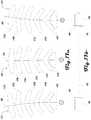
- FIG. 11illustrates pairs of bellows washers coupled to respective hub units of a hub assembly.
- FIG. 12illustrates a side view of a pair of bellows disposed within and supported by washers.
- FIGS. 13 a and 13 billustrate respective side and top views of the washers in accordance with an embodiment
- FIG. 14illustrates one example embodiment of a washer that comprises inner and outer washer components, which can overlap each other and can be bound together and with the central hub assembly with fasteners through aligned mounting holes.
- FIG. 15illustrates a side view of a hub assembly in accordance with one embodiment.
- FIG. 16illustrates an exploded side view of the hub units of a hub assembly being separated.
- FIG. 17 aillustrates an exploded view of the hub assembly showing example configurations of the hub units when the actuator is in various configurations.
- FIG. 17 billustrates a side view of a flexure.
- FIG. 18is an exploded side view of a hub assembly with the body angles of the hub units illustrated increasing from the bottom to the top of the hub assembly.
- FIG. 19shows an example of a nozzle assembly that comprises a port of the first cap and a tube support.
- FIG. 20illustrates another example of a nozzle assembly that can be coupled to a bellows cap.
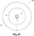
- FIG. 21is a top view of a bellows in accordance with an embodiment.
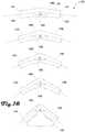
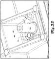
- FIGS. 22, 23 a and 23 billustrate a screw that fastens a flexure stop to the top plate in accordance with one example embodiment.
- FIGS. 26 a , 26 b and 26 cillustrate a die cast top plate in accordance with one embodiment.
- FIG. 27illustrates a bellows contact patch maintained with a super washer.
- FIGS. 28 a , 28 b , 29 a , 29 b , 30 a and 30 billustrate a die cast multi piece bottom plate of an actuator in accordance with an embodiment.
- FIGS. 31 a , 31 b , 32 a and 32 billustrate an example embodiment of a module clamps in accordance with one embodiment.
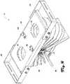
- FIGS. 1 a and 1 billustrate a respective top perspective and bottom perspective view of a solar tracker 100 in accordance with various embodiments.
- FIG. 2illustrates a side view of the solar tracker 100 .
- the solar tracker 100can comprise a plurality of photovoltaic cells 103 disposed along a length having axis X 1 and a plurality of pneumatic actuators 101 configured to collectively move the array of photovoltaic cells 103 .
- the photovoltaic cells 103are coupled to rails 102 that extend along parallel axes X 2 , which are parallel to axis X 1 .
- Each of the plurality of actuators 101extend between and are coupled to the rails 102 , with the actuators 101 being coupled to respective posts 104 .
- the posts 104can extend along an axis Z, which can be perpendicular to axes X 1 and X 2 in various embodiments.
- the actuators 101can be configured to collectively tilt the array of photovoltaic cells 103 based on an angle or position of the sun, which can be desirable for maximizing light exposure to the photovoltaic cells 103 and thereby maximizing, enhancing or optimizing electrical output of the photovoltaic cells 103 .
- the actuators 101can be configured to move the photovoltaic cells 103 between a plurality of configurations as shown in FIG. 2 , including a neutral configuration N where the photovoltaic cells 103 are disposed along axis Y that is perpendicular to axis Z.
- the actuators 101can be configured to move the photovoltaic cells 103 to a first maximum tilt position A, to a second maximum tilt position B, or any position therebetween.
- the angle between the neutral configuration N and the maximum tilt positions A, Bcan be any suitable angle, and in some embodiments, can be the same angle.
- Such movementcan be used to position the photovoltaic cells 103 toward the sun, relative to an angle of the sun, to reflect light toward a desired position, or the like.
- a solar tracker 100can comprise a plurality of photovoltaic cells 103 that are collectively actuated by four actuators 101 disposed along a common axis.
- a solar tracker 100can comprise any suitable number of actuators 101 including one, two, three, four, five, six, seven, eight, nine, ten, fifteen, twenty, fifty, one hundred, or the like.
- any suitable number of photovoltaic cells 103can be associated with a solar tracker 100 in further embodiments.
- any suitable size, shape or type of photovoltaic cells 103can be associated with a solar tracker 100 in further embodiments.
- actuators 101can be used to move various other objects or structures, including mirrors, reflectors, imaging devices, water purification, water collection, communications devices, and the like.
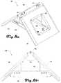
- FIG. 3illustrates examples of solar tracker arrays 300 having a plurality of solar trackers 100 arranged in a linearly aligned row on a portion of the ground 301 having increasing slopes in accordance with four respective example embodiments 300 A, 300 B, 300 C, 300 D.
- the first embodiment 300 Ahas the least slope and shows the trackers having posts 104 that are substantially the same length with the axis of the four solar trackers 100 conforming to the slope of the ground 301 and generally aligned along a common axis.
- the second embodiment 300 Bshows pairs of solar trackers 100 aligned along a common axis that is perpendicular to the pull of gravity (or parallel to level ground), with the pairs being disposed at different axes at different heights above the ground 301 .
- the third embodiment 300 Cshows solar trackers 100 aligned in parallel, but not coincident axes that are perpendicular to the pull of gravity (or parallel to level ground), with the solar trackers 100 each being disposed at different axes at different heights above the ground 301 .
- the fourth embodiment 300 Dshows solar trackers 100 aligned in parallel, but not coincident axes, that are not perpendicular to the pull of gravity (or parallel to level ground), with the solar trackers 100 each being disposed at different axes at different heights above the ground 301 .
- a Z axis of an actuator 101can be installed skew to a Z-axis of a post 104 associated with the actuator 101 .
- the solar trackers 100 of a solar tracker array 300can be pneumatically or fluidically coupled via a pneumatic or fluidic system that can actuate the solar trackers 100 of the solar tracker array 300 in unison. In other words, the solar trackers 100 of the solar tracker array 300 can be driven collectively to have the same angle.
- FIG. 3illustrates four example embodiments 300 A, 300 B, 300 C, 300 D of solar tracker arrays 300 , these examples should not be construed to be limiting on the wide variety of alternative embodiments that are within the scope and spirit of the present disclosure.
- FIG. 3shows solar tracker arrays 300 having solar trackers 100 aligned in linear rows, further embodiments can have tracker arrays 300 aligned in any suitable way, including an arc, a series of parallel rows, and the like.
- solar tracker arrays 300can comprise any suitable number of solar trackers 100 .
- a plurality of solar tracker arrays 300can be configured into a solar tracker system.
- Some embodimentscan include one or more of a ballasted actuator version with no bottom plate, a torque tube or a custom module mounting.
- Further embodimentscan include an expanded web beam, comprising a web of an I-beam or C-channel that can be slit with three offset rows of slits and expanded like expanded metal to form triangular trusses in the web and a higher stiffness beam.
- racking configurationscan include torque tubes, c-channels, extruded aluminum sections, custom roll formed shapes, hot rolled steel sections, and the like.
- Still further embodimentscan include ballast under the actuator modules to reduce the center of mass height, and such reduced center of mass height can lead to better tracking performance.
- Other embodimentscan include a terrain-following tracker, which can comprise non-moment carrying racking connections to allow the tracker 100 to be installed with variable slope throughout the length of the tracker 100 .
- Some embodimentscan include any suitable damper or damper system for flutter reduction, including a centrifugal clutch, viscous damper, viscoelastic materials, friction damper, linear damper, rotary damper, or the like.
- FIG. 4illustrates a perspective view of an actuator 101 in accordance with one embodiment.
- FIG. 5illustrates a side view of the actuator 101 of FIG. 4 .
- FIG. 6illustrates a bottom view of the actuator of FIGS. 4 and 5 .
- FIG. 7illustrates a top view of the actuator 101 of FIGS. 4-6 .
- the actuator 101comprises a V-shaped bottom plate 410 , a planar top-plate 430 , and a set of washers 450 that are disposed between the top and bottom plates 430 , 410 .
- the washers 450are coupled to a hub assembly 470 that extends between the bottom and top plates 410 , 430 .
- a pair of flexures 490can also extend between the bottom and top plates 410 , 430 and engage the one or more hub assembly 470 .
- a pair of spreader brackets 495can extend from edges of the top plate 430 .
- FIGS. 4-7illustrate the actuator 101 in a neutral configuration (see FIG. 2 ), where in the top plate 430 and spreader brackets 495 extend along perpendicular axes X A , Y A , which are both perpendicular to axis Z A in the neutral configuration.
- the top plate 430can be configured to tilt to the left and right.
- Components of an actuator 101can comprise various suitable materials, including metal (e.g., steel, aluminum, iron, titanium, or the like), plastic, or the like.
- metal partscan be coated for corrosion prevention (e.g., hot dip galvanized, pre galvanized, non-zinc based corrosion resistant coatings, or the like). Components of the actuator 101 and use thereof is discussed in more detail below.
- FIGS. 8 a and 8 billustrate respective perspective and side views of a bottom plate 410 of an actuator 101 in accordance with an embodiment and FIGS. 9 a and 9 b illustrate respective top and bottom views of the bottom plate 410 of the embodiment of FIGS. 8 a and 8 b .
- the bottom plate 410comprises a pair of plate arms 411 and a base 412 that extends between and couples to the plate arms 411 .
- the plate arms 411can extend from a planar cap 413 at an angle of ⁇ BP .
- the base 412can extend along an axis Y BP , which is perpendicular to axis Z BP , which bisects the cap 413 and angle ⁇ BP and is coincident with a plane of symmetry of the bottom plate 410 .
- the cap 413can define a pair of cap coupling slots 414 , which can be configured to couple with and engage respective flexures 490 (see, e.g., FIGS. 4-7 and 17 a ) that extend between the bottom plate 410 and the top plate 430 as described in more detail herein.
- the plate arms 411can define planar faces that define bottom plate coupling ports 415 , which can be configured to couple with bellows 1200 (see, e.g., FIGS. 12 and 19-21 ) as described in more detail herein.
- a thin metal plate, super washere.g., a super washer 2700 as shown in FIG. 27
- a super washercan be incorporated between the bellows 1200 and the bottom plate 410 to maintain a desired contact surface between the bellows 1200 and the bottom plate 410 .
- the bottom plate 410can further comprise supports 416 that couple and reinforce a coupling of the plate arms 411 and the base 412 .
- the cap 413can further comprise a pair of rivet nuts 417 that hold bolts that secure the flexure stop 495 and can keep the flexure 490 in place (see, e.g., FIGS. 4, 5 and 15-18 ) as described in more detail herein.
- the bottom plate 410can be configured to couple with a post 104 (see, e.g., FIGS. 1 a, 1 b and 2 ) that couples the bottom plate 410 to the ground or other location.
- a pile interface bracketcan include two brackets. Pile interface brackets can be a folded, stamped, or punched sheet metal part, or the like, and can be made of various suitable materials (e.g., aluminum) and can be make via any suitable process including die casting, extrusion, roll forming, and the like.
- the pile interface bracketcan attach to flanges of actuators 101 , and can allow for various suitable types of adjustment, including adjustment vertically, angular adjustment (e.g., in two axes), east-west adjustment, to follow slopes, to mate with piles that were driven out of spec, and the like.
- the pile interface bracketcan be installed with bolts, or other suitable coupler.
- pile interface bracketscan be absent.
- some configurationscan mount an actuator 101 directly to a post 104 without an adapter plate.
- the bottom platecan be configured 410 to couple with other suitable structures that allow the bottom plate 410 to be coupled with the ground or other location.
- the bottom plate 410can comprise a 90 degree angle, but in further embodiments, the angle of bottom plate 410 can be less than or greater than 90 degrees.
- the bellows 1200can constantly be in a curved orientation, which can be desirable in some examples because it can provide greater stiffness and control through range of motion (ROM).
- the bottom plate 410can be manufactured using high-volume sheet metal fabrication methods (e.g., progressive die, transfer press, die casting, and the like).
- the bottom plate 410can include stiffening features such as ribs, bosses, flanges, hems, and the like.
- Cap opening materialcan be bent in to mount to the bottom plate brace 412 , which can save material and remove extra parts.
- the base plate 410can be assembled using rivets, Tog-L-Tocs (BTM Corp.), spot welding, welding, bolts, or the like.
- the base plate 410can comprise super washers (e.g., super washer 2700 as shown in FIG. 27 ) under a bellows contact patch to prevent extrusion through a bellow cap hole 415 .
- the bottom plate 410can be made of multiple pieces.
- FIGS. 28 a , 28 b , 29 a , 29 b , 30 a and 30 billustrate an example of a die cast multi piece bottom plate 410 in accordance with an embodiment.
- the bottom plate 410can be made out of two identical pieces that nest together, which in some examples can remove the need for a flexure stop given how pieces of the bottom late 410 mate together.
- Some embodimentscan have parts that can have secondary operations for holes not parallel to a pull direction. Further embodiments can include ledges to help with installation and/or alignment. Still further embodiments can include features to improve actuator packaging for shipment to solar sites.
- one or both of the plates 410 , 430can comprise a “pillow plate,” which can be formed via thin-gauge stampings bonded to create a stiff/strong shell structure.
- Some embodimentscan include a reduced width of a bottom plate substructure compared to some examples discussed and shown herein.
- a bellows contact patchcan be maintained with a super washer 2700 as shown in FIG. 27 .
- Another examplecan include a plate with a bow-tie shape (e.g., from a top view) and tapered ends from a side view, which can provide a moment optimized beam out of a rectangular piece of material.
- the bottom plate brace 412can be absent.
- a post 104e.g., disposed in the ground and connected to the actuator 101 ) can be used as a compressive element in the structure of the bottom plate 410 .
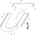
- FIG. 10illustrates a perspective view of a top plate 430 including spreader brackets 497 extending from edges thereof.
- the top plate 430is shown defining a pair of top plate coupling ports 431 which can be configured to couple with bellows 1200 (see, e.g., FIGS. 12 and 19-21 ) as described in more detail herein.
- a bellows 1200can couple with the top plate 430 at one end via a top plate coupling port 431 and the bellows 1200 can couple with a bottom plate coupling port 415 at a second end of the bellows 1200 .
- a pair of bellows 1200can be coupled between the top plate coupling ports 431 and the bottom plate coupling ports 415 .
- the top plate 430can define a pair of top plate coupling slots 432 , which can be configured to couple with and engage respective flexures 490 (see, e.g., FIGS. 4-7 and 17 a ) that extend between the bottom plate 410 and the top plate 430 as described in more detail herein.
- the top plate 430can further comprise a pair of insert nuts 433 that extend from below the face of top plate 430 and are configured to couple with respective hub assemblies 470 (see, e.g., FIGS. 4, 5 and 15-18 ) as described in more detail herein.
- the insert nuts 433can couple with a screw 2200 that fastens a flexure stop to the top plate 430 as shown in the examples embodiments of FIGS. 22, 23 a and 23 b.
- the top plate 430can comprise a rectangular body having a pair of opposing sidewalls 434 and a pair of opposing endwalls 435 .
- the spreader brackets 495are shown having a pair of arms 496 that extend from a web 497 , with the arms coupled to the sidewalls 434 of the top plate 430 via bolts 498 .
- the top plate 430can be made through any suitable process including laser cutting, sheet metal bending, stamping, die casting, and the like.
- the top plate 430can comprise die cast in aluminum.
- a die cast top plate 430(e.g., as shown in FIGS. 26 a , 26 b and 26 c ) can comprise 3D features such as ribs, bosses, pockets and the like. Such features can help to optimize material utilization by creating structurally efficient sections and/or by putting material where it is needed and not putting material where it is superfluous.
- the top plate 430may also include features (e.g., holes, bosses, etc.) that can help to align or mount various actuator peripherals.
- One such featurecan include a hole that accepts a zip tie that bundles and secures a pneumatic harness.
- Another such featurecan include a boss that accepts a square nut and that can be used to mount an inclinomoter or any other sensor to the actuator 101 .
- the spreader brackets 495can be generally U-shaped and configured to couple with portions of a solar tracker 100 such as rails 102 or the like (see FIGS. 1 a, 1 b and 2 ). Accordingly, having the spreader brackets 495 slidably coupled to the top plate 430 or having spreader brackets 495 of different sizes or having a different shape or size, can be desirable in some embodiments, so that the actuator 101 can couple with solar trackers 100 having different configurations (e.g., having rails 102 or Z purlins that are different widths apart). However, in some embodiments, spreader brackets 495 can be absent.
- some configurationscan extend the top plate 430 to the desired width for module mounting with spreader brackets 495 used when a wider profile is needed.
- the top plate 430can comprise mounting slots formed into the end wall to mate with the holes in a z-purlin, which can be fastened together with bolts.
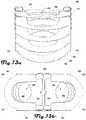
- FIGS. 11-14illustrate bellows washers 450 in accordance with various embodiments.
- FIG. 11illustrates pairs of bellows washers 450 coupled to respective hub units 473 of a hub assembly 470 .
- FIG. 12illustrates a side view of a pair of bellows 1200 disposed within and supported by washers 450 .
- FIGS. 13 a and 13 billustrate respective side and top views of the washers 450 in accordance with an embodiment and
- FIG. 14illustrates one example embodiment of a washer 450 that comprises inner and outer washer components 451 , 455 , which can overlap each other and can be bound together and with the central hub assembly 470 with fasteners 471 through aligned mounting holes 459 .
- the washers 450comprise an outer washer component 451 that is generally U-shaped having a rounded front edge 452 from which a pair of branches 453 extend.
- the branches 453 in this exampleinclude a rim 454 on an outer edge of the branches 453 with the rim extending perpendicular to a planar face defined by the front edge 452 and the branches 453 .
- the rim 154can comprise mounting holes 459 configured to couple the outer washer component 451 to the inner washer component 455 and to the central hub assembly 470 .
- fasteners 471e.g., bolts, rivets, or the like
- the inner washer component 455can comprise a crescent-shaped head 456 and arms that terminate at rims 457 having mounting holes 459 . As shown in FIG. 14 , the separate inner and outer washer components 451 , 455 can be configured to mate and form a washer 450 .
- FIGS. 11, 12, 13 a and 13 billustrate the inner and outer washer components 451 , 455 in a mated configuration and forming respective bellows cavities 458 defined by the front edge 452 and branches 453 of the outer washer component 451 and the head 456 of the inner washer component 455 .
- the inner and outer washer components 451 , 455can comprise bent, punched, or formed features. Such features include flanges, holes, windows, bosses cavities, or the like, which in some examples can aid in assembly by providing alignment or interface points for assembly tools, jigs or other fixtures. Inner and outer washer components 451 , 455 can be made with any suitable process including laser cutting, sheet metal being, progressive die stamping, die casting, and the like.
- bellows 1200are configured to extend through and engage with the bellows cavities 458 of the washers 450 .
- the bellows 1200can define convolutions defined by alternating valleys 1202 and peaks 1204 along the length of the bellows 1200 .
- the bellows cavities 458 of the washers 450can be configured to engage with valleys 1202 of the bellows 1200 as shown in FIG. 12 .
- the bellows cavities 458can be sized to allow the washers 450 to reside within the valleys 1202 of the bellows 1200 , but sized such that peaks 1204 cannot pass through bellows cavities 458 when the inner and outer washer components 451 , 455 are in a mated configuration.
- assembly of an actuator 101can include inserting a bellows 1200 within the front edge 452 and branches 453 of an outer washer component 451 with the front edge 452 and branches 453 engaging the bellows 1200 within a valley 1202 of the bellows 1200 .
- An inner washer component 455can then be coupled with the outer washer component 451 (e.g., as shown in FIG. 14 ) such that the head 456 of the inner washer component 455 engages the bellows 1200 within the same valley 1202 of the bellows 1200 as the outer washer component 451 .
- the washer 450can then be coupled to a hub unit 473 via fasteners 471 through aligned mounting holes 459 .
- a plurality of washers 450can be coupled about one or more bellows 1200 in a similar way.
- washers 450can be disposed within every other valley 1202 along a length of the bellows 1200 .
- further embodimentscan include any suitable alternative configurations of washers 450 engaging bellows 1200 .
- washers 450can engage every valley 1202 , every second valley 1202 , every third valley 1202 , every fourth valley 1202 , every fifth valley 1202 , every tenth valley 1202 , every twentieth valley 1202 , or the like, along a length of a bellows 1200 .
- Further embodimentscan include other repetitive or non-repetitive patterns along a length of a bellows 1200 .
- Still further embodimentscan include density of washers 450 within valleys 1202 increasing or decreasing along various lengths or portions of a bellows 1200 .
- washers 450can be spaced at every valley 1202 at a first end of a bellows 1200 and the spacing can be expanded to every second valley 1202 and then to every third valley 1202 toward a second end.
- washer spacingcan be more dense or sparse at a central portion of a bellows 1200 .
- an actuator 101can comprise a pair of bellows 1200 on opposing sides of a hub assembly 470 with five washers 450 associated with each bellows 1200 .
- each hub unit 473is shown associated with and coupled to a pair of washers 450 rigidly coupled on opposing sides of the hub units 473 and with the washers 450 of a given hub unit 473 being disposed at the same angle on the hub unit 473 .
- the angle between opposing washers 450 on a hub unit 473is shown increasing from the bottom end of the hub assembly 470 to the top end of the hub assembly 470 .
- embodimentscan include various suitable alternative configurations.
- other embodimentscan include any suitable number of washers 450 associated with a given bellows 1200 , including one, two, three, four, five, six, seven, eight, nine, ten, fifteen, twenty five, fifty, or the like.
- various embodimentscan include the same number of washers 450 on the bellows 1200
- some embodimentscan include a different number of washers 450 on some bellows 120 .
- embodimentsinclude an angle between opposing washers 450 on hub units 473 increasing at different angles from the bottom end to the top end of the hub assembly 470
- further embodimentscan include the same angle for some or all of the washers 450
- some embodimentscan include an angle between opposing washers 450 on hub units 473 decreasing at different angles from the bottom end to the top end of the hub assembly 470 .
- the washers 450 of an actuator 101can be disposed having a plane of symmetry Z W and Y W while in a neutral configuration N (see FIG. 2 ).
- one or both of such planes of symmetrycan be absent.
- the examples hereininclude embodiments of an actuator 101 having a pair of bellows 1200 associated with respective sets of washers 450 , further embodiments can include any suitable number bellows 1200 , including one, two, three, four, eight, or the like.
- Washers 450can be absent in some embodiments or can be replaced with other suitable structures or constraints, including a rope, chain, wire, insulation, or the like.
- Washers 450can be laser cut, waterjet cut, turret punched, stamped, or the like. In some embodiments, washers 450 can be pre-galvanized, powder-coated, or the like, for corrosion resistance. In some examples, washers 450 can be defined by inner and outer washer components 451 , 455 , which can overlap each other and can be bound together and with the central hub assembly 470 with fasteners 471 through aligned mounting holes 459 as discussed herein. Inner and outer washer portions 451 , 455 can comprise edge flanges 454 , 457 . Edge flanges 454 , 457 can provide stiffness, which can be desirable for repeatable and high-load performance.
- Edge flanges 454 , 457can be any suitable height or length in various embodiments. Additionally, edge flanges 454 , 457 or other suitable stiffening features can be incorporated, including ribs, bosses, cross breaks, and the like.
- mounting holes 459can be disposed on these flanges 454 , 457 and provide alignment features through which a fastener 471 can bind both washer components 451 , 455 to the hub assembly 470 .
- Inner washer portions 455can feature a cutout at the center rear that can act as a flexure pass-through, which can be desirable for assembly, rework and replacement.
- the inner washer portion 455 and/or outer washer portion 451can be defined by wire rope, a wire, or the like, instead of a flat plate as shown herein.
- a wire rope inner washercan be configured to take loading directed towards the center of actuator 101 .
- Other embodimentscan include a wire rope-to-washer mechanical bonding using fingers formed from a sheet washer and interlacing and crimping onto wire rope.
- Further embodimentscan comprise two-part steel washers with a split that is perpendicular to the split illustrated in the example embodiments of the drawings.
- the washers 450can comprise formed stiffening features (e.g., ribs, bosses, cross breaks, and the like), which can increase material efficiency.
- Some embodimentscan comprise an inner washer portion 455 mated to an outer washer portion 451 , instead of being mated to the hub assembly 470 .
- some embodimentscan build the washer/bellow assembly before mating to the hub assembly 470 , which can reduce assembly time, reduce tolerance stack issues relative to overlapping inner/outer portions, and the like.
- Further embodimentscan comprise a two part adjustable length inner washer 455 formed by coupling (e.g., riveting) two parts together via thru holes that are arranged in a Vernier pattern.
- Still further examplescan comprise a washer and spacer in one, which can include a washer that comprises two pieces of sheet material elastically bent at two different curvatures to form a thick center portion that serves as the spacer.
- FIGS. 15, 16, 17 a and 18illustrate embodiments of a hub assembly 470 having a plurality of hub units 473
- FIG. 17 billustrates an example embodiment of a flexure 490 that can be associated with a hub assembly 470
- FIG. 15illustrates a side view of a hub assembly 470 in accordance with one embodiment
- FIG. 16illustrates an exploded side view of the hub units 473 of a hub assembly 470 being separated
- FIG. 17 aillustrates an exploded view of the hub assembly 470 showing example configurations of the hub units 473 when the actuator 101 is in various configurations
- FIG. 18is an exploded side view of a hub assembly 470 with the body angles of the hub units 473 illustrated increasing from the bottom to the top of the hub assembly 470
- FIGS. 24 and 25illustrate a die cast hub assembly in accordance with another embodiment.
- a hub assembly 470can comprise a plurality of hub units 473 , with this example embodiment having five hub units 473 A, 473 B, 473 C, 473 D, 473 E.
- Each of the hub units 473is shown comprising a pair of hub arms 474 , a bottom end 475 , a top end 476 and a flexure slot 477 extending between the top and bottom ends 475 , 476 .
- the base hub unit 473 Eis shown comprising a hub base 478 at the bottom end 475 E of the base hub unit 473 E.
- the hub units 473can be separate bodies that are stacked to define at least a portion of the hub assembly 470 . More specifically, as shown in these examples, a first hub unit 473 A can be stacked on a second hub unit 473 B, with the concave bottom end 475 A of the first hub unit 473 A engaging the convex top end 476 B of the second hub unit 473 B.
- the concave bottom end 475 B of the second hub unit 473 Bcan engage the convex top end 476 C of the third hub unit 473 C.
- the concave bottom end 475 C of the third hub unit 473 Ccan engage the convex top end 476 D of the fourth hub unit 473 D.
- the concave bottom end 475 D of the fourth hub unit 473 Dcan engage the convex top end 476 E of the fifth hub unit 473 E.
- flexure slots 477 A, 477 B, 477 C, 477 D, 477 E of the hub units 473 A, 473 B, 473 C, 473 D, 473 Ecan be aligned such that a flexure 491 can be disposed and extend within the flexure slots 477 from the top end 476 A of the first hub unit 473 A to the bottom end 475 E of the fifth hub unit 473 E (e.g., as shown in FIG. 5 ).
- a flexure 490can comprise a line 491 that extends between a pair of flexure stops 492 that comprise flexure washers 493 .
- the width of the line 491can be smaller than the width of the flexure stops 492 and the flexure washers 493 .
- the width of the line 491can be configured to correspond to a width of the flexure slots 477 such that the line 491 can be disposed and extend within the flexure slots 477 from the top end 476 A of the first hub unit 473 A to the bottom end 475 E of the fifth hub unit 473 E.
- Hub units 473can be fabricated in any suitable manner.
- a plastic injection molded hub shellcan be paired with a metal insert or cladding.
- the plastic shellcan act as an interface between adjacent hub units 473 as well and/or as an interface between the hub units 473 and a flexure 490 .
- the shellcan comprise a material that has a small coefficient of friction and/or desirable wear properties.
- Metal claddingcan be inserted into a pocket or other feature molded into the plastic shell.
- the claddingcan act as a structural component and can bear loads applied by bellows 1200 (see FIG. 12 ) to the washers 450 and can transfer such loads through the hub units 473 and ultimately to the flexure 490 .
- the hub units 473can comprise die cast in aluminum. Hub units 473 can bear on one another while retaining structural integrity when subjected to applied loads. Hub units 473 can be designed in some examples so that each wing of a mating washer is only secured by a single fastener, be it a screw, rivet or the like.
- flexure stops 492can engage and couple with the top and bottom plates 430 , 410 .
- flexure stops 492can extend through and engage cap coupling slots 414 of the bottom plate 410 (see FIGS. 8 a , 9 a and 9 b ) and can extend through and engage coupling slots 432 of the top plate 430 (see. FIG. 10 ).
- the flexure stops 492can be configured to pass through a first portion of the coupling slots 414 , 432 and then be held (i.e., be configured to not pass through a second portion of the slots 414 , 432 .
- a stop tab 495can further secure and hold the flexure stops 492 .
- the line 491can pass through the coupling slots 414 , 432 and some or all of the flexure stops 492 (e.g., the flexure washers 493 ) can be coupled with the line 491 to secure the line 491 .
- Flexure stops 492 for the bottom and top plates 410 , 430can be different, identical or interchangeable.
- the flexure stop 492includes a single fastening hole.
- the flexure stopcomprises an open ended slot that acts as a flexure capture.
- a rivet or nut in the top plate 430 and/or bottom plate 410can provide a fixed feature to fasten to.
- a separate flexure stop 492can be absent.
- a flange on a flexure swagecan be seated in a depression feature on either of a top or bottom plate 410 , 430 .
- a fastener, a self-tapping screw, cotter pin or likewise,can bind the flexure swage to the seating feature.
- the line 491can be made of various suitable materials, including a metal, plastic, Spectra, composite material, or the like.
- the line 491can comprise a metal wire rope.
- the lengths of the flexure 490can be shorter than in configurations having a flat top and bottom plate 410 , 430 , which can be desirable for providing a shorter moment arm, better dead load/active load performance, and the like.
- the flexure 490can be coated or un-coated.
- a swage or termination of the flexure 490can be fitted with a rubber cap to cover an exposed wire rope.
- Some embodimentscan include a flange turned into a flexure crimp, which can eliminate the need for floating washers in some examples, while maintaining a large load spreading bearing surface on one or both terminations of the flexure 490 .
- the flexure 490can be defined by a chain, or other suitable structure integrated with the hub assembly 470 . Still further embodiments, can comprise four flexures 490 per actuator 101 creating a four-bar-linkage-like arrangement, which can move the virtual pivot above the top plate 430 .
- FIG. 17 aillustrates an example of a flexure 490 bending and flexing in response to movement of hub units 473 .
- the hub units 473are shown spaced apart for purposes of illustration, but in various embodiments, the hub units 473 can be stacked as shown, for example, in FIG. 15 .
- a hub assembly 470is shown in a neutral configuration N and in left and right bend configuration L, R.
- the neutral configuration Ncan be a configuration where the flexure 490 is linear and unbent or flexed.
- the hub assembly 470can be aligned linearly and have a plane of symmetry that is coincident with the centrally located flexure 490 .
- the neutral configuration N of FIG. 17 acan be present when a solar tracker 100 , for example as shown in FIG. 3 , is in the neutral configuration N.
- the hub units 473can be configured to shift to the left and right L, R, which causes the flexure 490 to flex along the length of the flexure 490 .
- bellows 1200 of an actuator 101can be inflated and/or deflated which can cause the bellows 1200 to expand and/or contract along a length of the bellows 1200 and cause movement of washers 450 surrounding the bellows 1200 .
- Such movement of the washers 450can in turn cause rotation, movement or pivoting of the hub units 473 of the hub assembly 470 as shown in FIG. 17 a .
- such pivoting of hub units 473 of the hub assembly 470can be generated when a solar tracker 100 is moving between a neutral position N and the maximum tilt positions A, B as shown in FIG. 2 .
- FIG. 17 aillustrates the hub units 473 of the hub assembly 470 being spaced apart, where the hub units 473 are stacked and engaged via respective bottom portions 475 and top portions 476 , such engagement can provide a moving interface between respective hub units 473 that allows the hub units 473 to tilt while staying engaged. Accordingly, respective concave and convex configurations of the bottom and top portions 476 , 475 of the hub units can be desirable to provide for such a movable interface.
- the arms 474 of the hub units 473can be disposed along axes that having an angle therebetween.
- a first hub unit 473 Acan have arms 474 A disposed at an angle of ⁇ A
- a second hub unit 473 Bcan have arms 474 B disposed at an angle of ⁇ B
- a third hub unit 473 Ccan have arms 474 C disposed at an angle of ⁇ C
- a fourth hub unit 473 Dcan have arms 474 D disposed at an angle of ⁇ D
- a fifth hub unit 473 Ecan have arms 474 E disposed at an angle of ⁇ E .
- angle ⁇ Bis smaller than angle ⁇ A
- angle ⁇ cis smaller than angle ⁇ B
- angle ⁇ Dis smaller than angle ⁇ C
- angle ⁇ Eis smaller than angle ⁇ D .
- angle ⁇ Ais shown being less than 180°.
- angles ⁇ of the arms 473can be the same.
- the angles of the arms 473can increase moving downward, can be increasing moving toward a center, can be decreasing toward a center, or can be alternatingly increasing or decreasing.
- all angles ⁇ of the arms 473can be within the range of 180° and 90°. In further embodiments, all angles ⁇ of the arms 473 can be within the range of 180° and 0°.
- an actuator 101can comprise a pair of opposing hub assemblies 470 that both extend between the top and bottom plates 410 , 430 parallel to axis Z A ( FIG. 5 ) and centrally aligned along axis to axis X A ( FIG. 6 ).
- the hub assemblies 470can comprise an axis of symmetry that is coincident with axes Z A and X A .
- the actuator 101 and portions thereof, including the bottom plate 410 , top plate 430 , washers 450 , flexures 490 and the likecan comprise an axis of symmetry that is coincident with axes Z A and X A .
- the hub assemblies 470can define flexure slots 477 that open inwardly toward a central slot 1110 between respective pairs of opposing washers 450 .
- flexure slots 477can open in any suitable direction (e.g., outwardly) and may or may not have an opposing orientation.
- the flexure slots 477can be substantially closed and defined by holes extending through the hub units 473 .
- the flexure slots 477can take the form of a constant section channel or can vary in width along the length of the flexure slots 477 .
- a flexure channelcan have an hourglass shape, where the center of the channel retains a relatively narrow width and the channel tapers to widen at the extreme ends of the channel.
- Various embodimentscan be configured to reduce stress on a hub flexure interface, and/or to reduce abrasion, fatigue failure, and the like.
- hub assemblies 470there can be any suitable number of hub assemblies 470 , including one, two, three, four, five, six, seven, eight, or the like. Also, while various examples herein discuss each hub assembly 470 being associated with one flexure 490 , in further embodiments, one or more hub assembly 470 can be associated with a plurality of flexures 490 .
- hub assemblies 470 having five hub units 473further embodiments can include one or more hub assembly having any suitable number of hub units 473 , including one, two, three, four, five, six, seven, eight, nine, ten, fifteen, twenty five, or the like.
- a given hub unit 473can be associated with any suitable number of washers 450 or may not be associated with any washers 450 in some embodiments. Accordingly, the examples herein having each hub unit 473 associated with a pair of opposing washers 450 should not be construed to be limiting on the wide variety of alternative configurations that are within the scope and spirit of the present disclosure.
- the actuator hub assembly 470can include a plastic spacer and metal cladding.
- the plastic spacercan be waterjet cut, machined, injection molded, extruded, or the like.
- the actuator hub assembly 470can be assembled using rivets, bolts, screws, and the like. With rivets, in various embodiments, fastener part count can be halved and assembly complexities can be eliminated without need for an insert nut.
- portions of the actuator hub assembly 470can be made of plastic, which can comprise or be coated in any suitable polymer, including HDPE, nylon, Acetal, PTFE, a rate-stiffening polymer or the like.
- Metal claddingcan be stamped, laser cut, waterjet cut, punch pressed, or the like.
- claddingcan be pre-galvanized, hot-dip galvanized, powder coated, painted, or the like, to provide corrosion protection.
- claddingcan comprise any suitable number of layers, including one, two, three, four, five, six, or the like.
- the actuator hub assembly 470can keep each set of washers 450 a specific distance away and washer spacing off-center can be tuned based on geometric modeling and empirical data. The hub assembly 470 can maintain the angle of each set of washers 450 , with the washer angle between pairs of washers 450 decreasing from the top hub unit 473 A to the bottom hub unit 473 E as discussed herein.
- the actuator hub assembly 470provides structure under heavy compressive external loads and depressurization.
- the hub assembly 470can support non-trivial internal compression loads caused by bellows 1200 pressurization in various embodiments.
- Hub units 473can have various suitable fasteners.
- some embodimentscan include a single fastener per side, which can be desirable because it can reduce fastener hardware, and enable easier manual or automated assembly.
- some embodimentscan comprise a thin cladding or skin.
- some embodimentscan comprise a hub-flexure interface rather than washer-flexure interface, which can be desirable because such a configuration can provide more bearing area and can avoid washers 450 wearing into the flexure.
- FIGS. 19-21illustrate examples of bellows 1200 in accordance with some embodiments, which can comprise a portion of an actuator 101 as shown in FIG. 12 . More specifically, FIGS. 19 and 20 are side views of example embodiments of a bellows 1200 and FIG. 21 is a top view of a bellows 1200 in accordance with an embodiment.
- a bellows 1200can comprise a convoluted body defined by repeating alternating valleys 1202 and peaks 1204 extending between a first and second end 1206 , 1208 .
- An open bellows cap 1210can be disposed at the first end 1206 and a closed bellows cap 1212 can be disposed at the second end 1208 .
- the bellows caps 1210 , 1212can have a maximum diameter that is smaller than a maximum and/or minimum diameter of the convolutions of the bellows 1200 .
- a bellows 1200can be generally cylindrical with a central axis X B along which the bellows 1200 extends.
- the bellows 1200 and portions thereofcan have one or more axis of symmetry about central axis X B .
- the convolutions of the bellows 1200can have circular radial symmetry and/or axial symmetry about central axis X B between the first and second ends 1206 , 1208 or at least a portion thereof.
- the bellows caps 1210 , 1212can comprise flat sidewalls 1211 on one or more sides of the caps 1210 , 1212 .
- An example having four flat sidewalls 1211is shown in FIG. 21 , but in further examples, the bellows caps 1210 , 1212 can include any suitable number of flat sidewalls, including one, two, three, four, five, six, ten, twenty, or the like.
- the caps 1210 , 1212can be configured to engage with and be held by portions of the top and bottom plates 410 , 430 .
- the caps 1210 , 1212can be configured to be respectively coupled within a bottom plate coupling port 415 (see FIGS. 8 a and 9 a ) and a top plate coupling port 431 (see FIGS. 4, 7 and 10 ).
- the caps 1210 , 1212 and coupling ports 415 , 431can be configured to provide a coupling therebetween that resists rotation of the bellows 1200 within the coupling ports 415 , 431 .
- the coupling ports 415 , 431can be generally polygonal and/or comprise one or more linear sides and the caps 1210 , 1212 can also be generally polygonal and/or comprise one or more linear sides that correspond to the size and shape of the coupling ports 415 , 431 .
- the top plate coupling ports 431have four flat sides between rounded portions, which can correspond to the size and shape of the cap 1210 and flat sidewalls 1211 as shown in FIG. 20 , for example. Such a correspondence can thereby allow the cap 1210 to extend within a top plate coupling port 431 and resist rotation of the bellows 1200 within the top plate coupling port 431 based at least on engagement of the flat sidewalls 1211 with corresponding flat edges of the coupling port 431 .
- the bottom plate coupling ports 415have four flat sides between rounded portions, which can correspond to the size and shape of the cap 1210 and flat sidewalls 1211 as shown in FIG. 20 , for example. Such a correspondence can thereby allow the cap 1210 to extend within a bottom plate coupling port 415 and resist rotation of the bellows 1200 within the bottom plate coupling port 415 based at least on engagement of the flat sidewalls 1211 with corresponding flat edges of the coupling port 415 .
- bellows 1200can include pockets and/or depressions on bellows cap flats 1211 . These features can be used for retention of bellows 1200 into top and bottom plates 410 , 430 (e.g., to keep bellows caps seated). Such retention features can be incorporated into the bellows 1200 , into a plate 410 , 420 , and/or as a separate part. In one example, such a feature can be molded in the bellows 1200 including a circumferential top cap slot with domed bosses for snap fit.
- such a featurecan be cut into a top and/or bottom plate 410 , 430 , including one or more tangs on mating ports on plates including formed bosses for snap fit.
- such a featurecan comprise a separate part including a circlip, bonded nubs, wire rope lasso, or the like.
- the bellows 1200 and other portions of an actuator 101can comprise any suitable material including a material configured for rate-dependent stiffening, including non-Newtonian materials. Geometry of a bellows 1200 can be achieved in various suitable ways, including via stamping, which can include beads and/or other stiffening features in the bellow contact patch, extruded material around a bellow cap hole, and the like.
- the caps 1210 , 1212 of the bellows 1200can be any suitable shape in various embodiments.
- the bellow caps 1210 , 1212can be round which can be desirable for enhancing even material distribution during a molding process and reducing cost in forming of plate mating features.
- the bellows 1200can be made in various suitable ways.
- the bellows 1200can be hydroformed, which can comprise a variation on injection stretch blow molding.
- Such a processcan use the property of a polymer to perform molding at room-temperature at extremely high pressure into a secondary mold to stretch to beyond final dimension (e.g., 600% elongation) and then relax to a final dimension at (e.g., 350% elongation).
- Thiscan allow a bellows blow mold to have a small stretch ratio while hot, and can improve the material properties of the bellows 1200 , which can allow for the same.
- Further embodimentscan comprise coextrusion, which in one example can use an external layer that is less costly and with higher ultra-violet (UV) resistance as a sacrificial element to increase UV resistance of whole part.
- some embodimentscan comprise flexible bellows paint, which can comprise coating the bellows 1200 post-molding to increase UV resistance.
- bellows caps 1210 , 1212can be generated during the molding process or can be welded on in a separate step.
- the convoluted body of the bellows 1200can be made via a continuous blow molding process like corrugated pipe and the caps 1210 , 1212 can be welded on afterwards.
- the bellows 1200can comprise various suitable openings that can allow fluid to be introduced and/or removed from an internal cavity of the hollow bellows 1200 .
- FIG. 19shows an example of a connector assembly 1214 that comprises a port 1216 of the first cap 1210 and a tube support 1218 that can be disposed with the port 1216 .
- Hose clamps 1220can couple a fluid hose 1222 to the port 1216 and to an end of a bent connector nozzle 1224 .
- the tube support 1218can be configured to provide compression resistance for the bellows 1200 (e.g., where the bellows 1200 comprises a soft materials), which can be desirable for preventing the connector assembly 1214 from relieving compression and leaking.
- FIG. 20illustrates another example of a connector assembly 1214 that can be coupled to the first cap 1210 in various suitable ways, including adhesive bonding, contact welding, hot tool polymer welding, hot plate welding, spin welding, friction welding, ultrasonic welding, high frequency welding, radio frequency welding, solvent welding, hot gas welding, radiant welding, infrared welding, laser welding, hot wire welding, heat sealing, or the like.
- joining an independently manufactured nozzlecan be desirable, because such a configuration can decouple the manufacturing capabilities of the process by which the bellows 1200 and nozzle are made. For instance, by manufacturing the nozzle independently it can be possible to maintain higher tolerances, maintain surface finishes, and include features that are not possible in a bellow manufacturing process. Additionally, it can possible to manufacture the nozzle from a different material with different properties than that of the bellows 1200 .
- a flow restricting orificecan control a fluid flow rate entering the bellows 1200 .
- the nozzlecan provides a bore and/or sealing surface where a flow restriction element can be installed.
- a set screw orifice with an external threaded surfacecan be driven into the internal bore of the nozzle.
- the set screw orificecan have a conical tip which can mate with a sealing surface on the nozzle.
- the set screw orificecan have a small hole controlling fluid flow rate across the assembly.
- the bellows 1200can be selectively inflated and/or deflated to cause movement of the top plate 430 relative to the bottom plate. Examples of systems and methods for controlling and actuation via bellows 1200 of an actuator 101 are discussed in more detail in the applications incorporated by reference herein.
- FIGS. 31 a , 31 b , 32 a and 32 billustrate an example embodiment of a module clamp 3100 in accordance with one embodiment, which can be used to secure photovoltaic modules 103 to a racking system of a solar tracker 100 .
- the module clamp 3100can comprise a bolt 3110 that includes a flange head 3111 including serrations 3112 which can be configured to break anodization of modules to enable electric bonding.
- the bolt 3110can comprise a standard bolt with a sheet metal top cap, or with a captive washer.
- the module clamp 3100can also include a clamp head 3120 , which in some examples can comprise a formed sheet metal clamp (e.g., made of steel, extruded aluminum, die cast aluminum, or the like). Various examples of the clamp head 3120 can comprise sharp edges to pierce anodization. Some examples can include a tab to keep equal spacing between modules. Some examples can include a cinch nut. Some examples can include a female thread, rolled threads, a rivet nut, or any other captive nut.
Landscapes
- Engineering & Computer Science (AREA)
- Mechanical Engineering (AREA)
- Life Sciences & Earth Sciences (AREA)
- Sustainable Development (AREA)
- General Engineering & Computer Science (AREA)
- Physics & Mathematics (AREA)
- Chemical & Material Sciences (AREA)
- Thermal Sciences (AREA)
- Sustainable Energy (AREA)
- Combustion & Propulsion (AREA)
- Fluid Mechanics (AREA)
- Robotics (AREA)
- Actuator (AREA)
- Photovoltaic Devices (AREA)
- Fluid-Pressure Circuits (AREA)
- Fluid-Driven Valves (AREA)
- Hydraulic Clutches, Magnetic Clutches, Fluid Clutches, And Fluid Joints (AREA)
- Jib Cranes (AREA)
- Diaphragms And Bellows (AREA)
Abstract
Description
Claims (9)
Priority Applications (2)
| Application Number | Priority Date | Filing Date | Title |
|---|---|---|---|
| US15/955,044US10917038B2 (en) | 2017-04-17 | 2018-04-17 | Pneumatic actuator system and method |
| US17/130,397US20210226578A1 (en) | 2017-04-17 | 2020-12-22 | Pneumatic actuator system and method |
Applications Claiming Priority (4)
| Application Number | Priority Date | Filing Date | Title |
|---|---|---|---|
| US201762486377P | 2017-04-17 | 2017-04-17 | |
| US201762486369P | 2017-04-17 | 2017-04-17 | |
| US201762486335P | 2017-04-17 | 2017-04-17 | |
| US15/955,044US10917038B2 (en) | 2017-04-17 | 2018-04-17 | Pneumatic actuator system and method |
Related Child Applications (1)
| Application Number | Title | Priority Date | Filing Date |
|---|---|---|---|
| US17/130,397ContinuationUS20210226578A1 (en) | 2017-04-17 | 2020-12-22 | Pneumatic actuator system and method |
Publications (2)
| Publication Number | Publication Date |
|---|---|
| US20180302025A1 US20180302025A1 (en) | 2018-10-18 |
| US10917038B2true US10917038B2 (en) | 2021-02-09 |
Family
ID=63790957
Family Applications (6)
| Application Number | Title | Priority Date | Filing Date |
|---|---|---|---|
| US15/955,044Expired - Fee RelatedUS10917038B2 (en) | 2017-04-17 | 2018-04-17 | Pneumatic actuator system and method |
| US15/955,519Expired - Fee RelatedUS10951159B2 (en) | 2017-04-17 | 2018-04-17 | Solar tracker control system and method |
| US15/955,506Expired - Fee RelatedUS10944353B2 (en) | 2017-04-17 | 2018-04-17 | Pneumatic actuation circuit system and method |
| US17/130,397AbandonedUS20210226578A1 (en) | 2017-04-17 | 2020-12-22 | Pneumatic actuator system and method |
| US17/178,152AbandonedUS20210194415A1 (en) | 2017-04-17 | 2021-02-17 | Fluidic actuation circuit system and method |
| US17/178,593AbandonedUS20210175841A1 (en) | 2017-04-17 | 2021-02-18 | Solar tracker stow system and method |
Family Applications After (5)
| Application Number | Title | Priority Date | Filing Date |
|---|---|---|---|
| US15/955,519Expired - Fee RelatedUS10951159B2 (en) | 2017-04-17 | 2018-04-17 | Solar tracker control system and method |
| US15/955,506Expired - Fee RelatedUS10944353B2 (en) | 2017-04-17 | 2018-04-17 | Pneumatic actuation circuit system and method |
| US17/130,397AbandonedUS20210226578A1 (en) | 2017-04-17 | 2020-12-22 | Pneumatic actuator system and method |
| US17/178,152AbandonedUS20210194415A1 (en) | 2017-04-17 | 2021-02-17 | Fluidic actuation circuit system and method |
| US17/178,593AbandonedUS20210175841A1 (en) | 2017-04-17 | 2021-02-18 | Solar tracker stow system and method |
Country Status (12)
| Country | Link |
|---|---|
| US (6) | US10917038B2 (en) |
| EP (4) | EP3613140A4 (en) |
| CN (2) | CN110521110B (en) |
| AU (5) | AU2018254424A1 (en) |
| BR (2) | BR112019021722A2 (en) |
| CL (1) | CL2019002938A1 (en) |
| CO (1) | CO2019011622A2 (en) |
| EC (1) | ECSP19081797A (en) |
| MX (2) | MX2019012429A (en) |
| PE (1) | PE20200309A1 (en) |
| TW (2) | TWI803490B (en) |
| WO (3) | WO2018195115A1 (en) |
Cited By (3)
| Publication number | Priority date | Publication date | Assignee | Title |
|---|---|---|---|---|
| US11683003B2 (en) | 2020-06-22 | 2023-06-20 | Sunfolding, Inc. | Locking, dampening and actuation systems and methods for solar trackers |
| US11772282B2 (en) | 2012-10-26 | 2023-10-03 | Sunfolding, Inc. | Fluidic solar actuation system |
| US11791764B2 (en) | 2015-01-30 | 2023-10-17 | Sunfolding, Inc. | Fluidic actuator system and method |
Families Citing this family (19)
| Publication number | Priority date | Publication date | Assignee | Title |
|---|---|---|---|---|
| US11431285B2 (en)* | 2016-07-08 | 2022-08-30 | Corosolar Llc | Dynamic stabilizer for solar trackers |
| US11502639B2 (en) | 2018-05-29 | 2022-11-15 | Sunfolding, Inc. | Tubular fluidic actuator system and method |
| US12253137B2 (en) | 2019-02-01 | 2025-03-18 | Stabilus Gmbh | Damping apparatus and method of using same |
| WO2021195232A1 (en) | 2020-03-24 | 2021-09-30 | Stabilus Gmbh | Piston assemblies and methods of using same |
| US11108353B1 (en) | 2020-07-14 | 2021-08-31 | FTC Solar, Inc. | Systems and methods for array level terrain based backtracking |
| US11139775B1 (en) | 2020-07-14 | 2021-10-05 | FTC Solar, Inc. | Systems and methods for terrain based backtracking for solar trackers |
| US11522491B2 (en) | 2020-08-26 | 2022-12-06 | FTC Solar, Inc. | Systems and methods for adaptive range of motion for solar trackers |
| US10935992B1 (en) | 2020-09-16 | 2021-03-02 | FTC Solar, Inc. | Systems and methods for solar trackers with diffuse light tracking |
| CN116568971A (en)* | 2020-10-16 | 2023-08-08 | 斯塔比卢斯有限责任公司 | Damping device and use method thereof |
| CN112383271B (en)* | 2020-11-11 | 2021-10-29 | 浙江欧亚光电科技有限公司 | Solar panel photic device based on gas heating expansion type |
| CN112518729B (en)* | 2020-12-16 | 2025-02-25 | 合肥工业大学 | An integrated torsion soft robot module |
| US11211896B1 (en) | 2021-01-14 | 2021-12-28 | FTC Solar, Inc. | Systems for damping a solar photovoltaic array tracker |
| IT202100001397A1 (en)* | 2021-01-26 | 2022-07-26 | Quantiqun S R L | RECTENNA FOR ENERGY CONVERSION |
| KR102537746B1 (en)* | 2021-06-30 | 2023-05-26 | 한국로봇융합연구원 | Stack Type Soft Actuator |
| US11695370B2 (en) | 2021-07-27 | 2023-07-04 | FTC Solar, Inc. | Locking assembly for a solar photovoltaic array tracker |
| US20230327604A1 (en)* | 2022-04-12 | 2023-10-12 | Sunfolding, Inc. | Solar module leading edge system and method |
| TWI800417B (en)* | 2022-06-27 | 2023-04-21 | 楊明坤 | Modular solar panel diversion and quick dismantling structure besides its quick dismantling method |
| WO2024233210A1 (en)* | 2023-05-05 | 2024-11-14 | Nextracker Llc | High efficiency gear box and holding system for solar trackers |
| TWD237082S (en) | 2023-07-10 | 2025-03-21 | 美商優比快公司 (美國) | Captured nut assembly |
Citations (93)
| Publication number | Priority date | Publication date | Assignee | Title |
|---|---|---|---|---|
| US979460A (en) | 1909-05-05 | 1910-12-27 | Weston M Fulton | Flexible corrugated-metal wall for collapsible and expansible vessels. |
| US2920656A (en) | 1956-10-19 | 1960-01-12 | Us Gasket Company | Reinforced bellows |
| US3284964A (en) | 1964-03-26 | 1966-11-15 | Saito Norio | Flexible beam structures |
| US3472062A (en) | 1967-09-13 | 1969-10-14 | Pathway Bellows Inc | Testable and pressurized multiple ply bellows |
| US3602047A (en) | 1969-06-24 | 1971-08-31 | Kistler Instr Corp | Servo pressure transducer |
| US3800398A (en) | 1972-12-14 | 1974-04-02 | E Harrington | Method of fabricating multiple-ply bellows |
| US3956543A (en) | 1972-10-02 | 1976-05-11 | Rockwell International Corporation | Shear flexibility for structures |
| US3982526A (en) | 1975-05-20 | 1976-09-28 | The United States Of America As Represented By The United States Energy Research And Development Administration | Turning collectors for solar radiation |
| US4063543A (en) | 1976-08-12 | 1977-12-20 | John Henry Hedger | Servo tracking apparatus |
| US4102326A (en) | 1977-09-28 | 1978-07-25 | Sommer Warren T | Central receiver solar collector using mechanically linked mirrors |
| US4120635A (en) | 1976-02-10 | 1978-10-17 | Erhard Langecker | Blow mold for the production of bellows made of a highly elastic plastic |
| US4154221A (en) | 1976-11-22 | 1979-05-15 | American Solar | Tracking system for solar energy collection |
| US4172443A (en) | 1978-05-31 | 1979-10-30 | Sommer Warren T | Central receiver solar collector using analog coupling mirror control |
| US4175540A (en) | 1977-05-18 | 1979-11-27 | Mel Modern Systems, Incorporated | Solar energy collector |
| US4185615A (en) | 1977-10-11 | 1980-01-29 | Bottum Edward W | Solar collector structure |
| US4198954A (en) | 1977-02-21 | 1980-04-22 | U.S. Philips Corporation | Solar collector, comprising solar tracking means |
| US4345582A (en) | 1979-11-19 | 1982-08-24 | Aharon Naaman B | System for the utilization of solar energy |
| US4424802A (en) | 1981-10-08 | 1984-01-10 | Sun Trac Industries, Inc. | Pneumatic drive for solar concentrators |
| US4459972A (en) | 1981-10-06 | 1984-07-17 | Veda Incorporated | Heliostat assembly |
| US4464980A (en) | 1980-06-19 | 1984-08-14 | Nihon Plast Co., Ltd. | Bellows actuator |
| US4494417A (en) | 1979-03-16 | 1985-01-22 | Robotgruppen Hb | Flexible arm, particularly a robot arm |
| US4566432A (en) | 1982-03-08 | 1986-01-28 | Ford Aerospace & Communications Corporation | Method for mass producing solar radiation reflectors |
| US4620771A (en) | 1984-09-06 | 1986-11-04 | So-Luminaire Systems Corp. | Combined solar tracking reflector and photovoltaic panel |
| SU1346918A1 (en) | 1985-11-05 | 1987-10-23 | Научно-Исследовательский И Проектно-Конструкторский Институт Плодоовощного Хозяйства | Solar heat collector |
| FR2603228A1 (en) | 1986-08-28 | 1988-03-04 | Aerospatiale | Composite tubular structures with high specific stiffness - for low mass and inertia for robotic members or machinery components for external use |
| US4751868A (en) | 1986-02-12 | 1988-06-21 | Paynter Henry M | Method and system employing double-acting, fluid-driven twistor-pairs as combined joints and motors in arthrobots |
| US4768871A (en) | 1985-06-29 | 1988-09-06 | Bernhard Mittelhauser | Mirror for motor vehicles |
| US4777868A (en)* | 1984-12-17 | 1988-10-18 | Komatsu Ltd. | Flexible actuator |
| US4784042A (en)* | 1986-02-12 | 1988-11-15 | Nathaniel A. Hardin | Method and system employing strings of opposed gaseous-fluid inflatable tension actuators in jointed arms, legs, beams and columns for controlling their movements |
| US4832001A (en) | 1987-05-28 | 1989-05-23 | Zomeworks Corporation | Lightweight solar panel support |
| US4848179A (en) | 1988-02-16 | 1989-07-18 | Trw Inc. | Flexidigit robotic manipulator |
| US4900218A (en) | 1983-04-07 | 1990-02-13 | Sutherland Ivan E | Robot arm structure |
| US4939982A (en) | 1985-06-24 | 1990-07-10 | Guy Immega | Axially contractable actuator |
| US4954952A (en) | 1988-02-16 | 1990-09-04 | Trw Inc. | Robotic arm systems |
| US4977790A (en)* | 1987-03-23 | 1990-12-18 | Kabushiki Kaisha Komatsu Seisakusho | Flexible arm |
| US5021798A (en) | 1988-02-16 | 1991-06-04 | Trw Inc. | Antenna with positionable reflector |
| US5040452A (en) | 1990-05-11 | 1991-08-20 | Kerkvoort Maarten J Van | Fluid actuators |
| US5080000A (en) | 1990-05-11 | 1992-01-14 | Bubic Frank R | Flexible robotic links and manipulator trunks made thereform |
| US5156081A (en) | 1989-12-20 | 1992-10-20 | Kabushiki Kaisha Toshiba | Gripping actuator with independently flexible cylinders |
| US5181452A (en) | 1991-11-22 | 1993-01-26 | Kinetic Sciences Inc. | Bellows actuator |
| US5251538A (en) | 1991-08-21 | 1993-10-12 | Battelle Memorial Institute | Prehensile apparatus |
| US5317952A (en) | 1991-11-22 | 1994-06-07 | Kinetic Sciences Inc. | Tentacle-like manipulators with adjustable tension lines |
| US5337732A (en) | 1992-09-16 | 1994-08-16 | Cedars-Sinai Medical Center | Robotic endoscopy |
| US5386741A (en) | 1993-06-07 | 1995-02-07 | Rennex; Brian G. | Robotic snake |
| US5469756A (en) | 1991-10-10 | 1995-11-28 | Siemens Aktiengesellschaft | Flexible robot arm |
| US5697285A (en) | 1995-12-21 | 1997-12-16 | Nappi; Bruce | Actuators for simulating muscle activity in robotics |
| US5816769A (en) | 1995-11-07 | 1998-10-06 | Siemens Aktiengesellschaft | Flexible manipulator |
| US6054529A (en) | 1997-04-08 | 2000-04-25 | The Procter & Gamble Co. | Blends of and methods of blending EVOH polymers and ethylene based polymers having improved environmental stress cracking or environmental fatigue resistance, and products therefrom |
| US6080927A (en) | 1994-09-15 | 2000-06-27 | Johnson; Colin Francis | Solar concentrator for heat and electricity |
| US6178872B1 (en) | 1998-07-24 | 2001-01-30 | Forschungszentrum Karlsruhe Gmbh | Operating mechanism |
| WO2001017731A1 (en) | 1999-09-09 | 2001-03-15 | Heriot-Watt University | Fluid operated actuator for robots |
| CA2330612A1 (en) | 2000-12-29 | 2002-06-29 | Alain Bernier | Flexible actuator |
| US6557804B1 (en) | 2001-12-05 | 2003-05-06 | The Boeing Company | Rotating solar concentrator |
| US6772673B2 (en) | 2001-12-13 | 2004-08-10 | Seiko Epson Corporation | Flexible actuator |
| US20050034752A1 (en) | 2003-07-28 | 2005-02-17 | William Gross | Solar concentrator array with grouped adjustable elements |
| US6875170B2 (en) | 2000-04-21 | 2005-04-05 | Universite Pierre Et Marie Curie | Positioning, exploration, and/or intervention device, in particular in the field of endoscopy and/or mini-invasive surgery |
| US20060049195A1 (en) | 2002-08-08 | 2006-03-09 | Sotiris Koussios | Pressurizable structures comprising different surface sections |
| US7331273B2 (en) | 2002-03-04 | 2008-02-19 | Prospective Concepts Ag | Pneumatic actuator |
| US20090097994A1 (en) | 2007-10-15 | 2009-04-16 | Unico, Inc. | Cranked Rod Pump Apparatus And Method |
| US20090115292A1 (en) | 2007-10-25 | 2009-05-07 | Massachusetts Institute Of Technology | Strain amplification devices and methods |
| US7531741B1 (en) | 2003-03-07 | 2009-05-12 | Sacred Power Corporation | Tracking solar shelter |
| US20090151775A1 (en) | 2007-12-17 | 2009-06-18 | Solar Integrated Technologies Gmbh | System for Assisting Solar Power Generation |
| WO2009108159A1 (en) | 2008-02-29 | 2009-09-03 | Cbe Global Holdings, Inc. | Multi-axis metamorphic actuator and drive system and method |
| US7614615B2 (en) | 2007-01-18 | 2009-11-10 | Bfs Diversified Products, Llc | Directional stabilizer ring and fluid spring assembly including same |
| US20090314119A1 (en) | 2006-10-13 | 2009-12-24 | Robotics Technology Leaders Gmbh | Worm-like mechanism |
| US20100043776A1 (en) | 2008-08-22 | 2010-02-25 | Skyfuel, Inc. | Hydraulic-Based Rotational System for Solar Concentrators that Resists High Wind Loads Without a Mechanical Lock |
| US20100125401A1 (en) | 2008-11-14 | 2010-05-20 | Gm Global Technology Operations, Inc. | Control systems and methods for estimating engine coolant heat loss |
| CO6180473A2 (en) | 2006-10-09 | 2010-07-19 | Cabanillas Ingenieros S L | MOBILE SOLAR PANEL SUPPORT SYSTEM |
| CN101783619A (en) | 2009-12-14 | 2010-07-21 | 干布太阳能股份有限公司 | Solar sun-tracking device structure |
| US20110073161A1 (en) | 2010-03-29 | 2011-03-31 | Sedona Energy Labs, Limited Company | High efficiency counterbalanced dual axis solar tracking array frame system |
| KR101034478B1 (en) | 2010-12-09 | 2011-05-17 | (주)현대에스더블유디산업 | Angle control device of solar generator using air pressure |
| WO2011094084A2 (en) | 2010-01-29 | 2011-08-04 | Halliburton Energy Services, Inc. | Control system for a surface controlled subsurface safety valve |
| WO2012015378A1 (en) | 2010-07-29 | 2012-02-02 | Micah Andretich | Sustainable, mobile, expandable structure |
| CO6450667A2 (en) | 2009-03-10 | 2012-05-31 | R E M S A P Revolution Energy Maker | SOLAR ENERGY COLLECTOR SYSTEM |
| US20120210818A1 (en) | 2009-12-15 | 2012-08-23 | Festo Ag & Co. Kg | Fluid-Operated Manipulator |
| US8305736B2 (en) | 2006-07-26 | 2012-11-06 | Eaton Corporation | Motor control center subunit having movable line contacts and method of manufacture |
| US20120285509A1 (en) | 2011-05-09 | 2012-11-15 | Anthony Surganov | Solar panel system and methods of passive tracking |
| KR20130019502A (en) | 2011-08-17 | 2013-02-27 | 엄분도 | Universial joint with the function of locking |
| CN103222067A (en) | 2010-11-30 | 2013-07-24 | 大金工业株式会社 | Solar panel unit |
| US20130306135A1 (en) | 2012-04-30 | 2013-11-21 | Nelson Planting | Inflatable, pressure-controlled, portable line-concentrating heliostat |
| US8657271B2 (en) | 2010-08-12 | 2014-02-25 | E I Du Pont De Nemours And Company | Thermoplastic jounce bumpers |
| US8700215B2 (en) | 2009-01-13 | 2014-04-15 | Panasonic Corporation | Control apparatus and control method of elastic body actuator as well as control program thereof |
| CN103786165A (en) | 2014-01-22 | 2014-05-14 | 北华大学 | Pneumatic space bending flexible joint |
| RU2516595C2 (en) | 2012-09-03 | 2014-05-20 | Федеральное Государственное Бюджетное Образовательное Учреждение Высшего Профессионального Образования "Саратовский Государственный Университет Имени Н.Г. Чернышевского" | Device for orientation of solar energy receiver |
| JP2014116360A (en) | 2012-12-06 | 2014-06-26 | Daikin Ind Ltd | Solar panel unit |
| US8899359B1 (en) | 2010-11-05 | 2014-12-02 | The Boeing Company | Locomotion system for robotic snake |
| US20150244309A1 (en) | 2012-09-28 | 2015-08-27 | Daikin Industries, Ltd. | Solar panel unit |
| US9133864B2 (en) | 2009-10-07 | 2015-09-15 | Simon Fraser University | Fluidic actuator and method of manufacture |
| WO2016123592A1 (en) | 2015-01-30 | 2016-08-04 | Sunfolding, Inc. | Fluidic actuator system and method |
| RU2611571C1 (en) | 2015-12-09 | 2017-02-28 | Федеральное государственное бюджетное учреждение науки Физико-технический институт им. А.Ф. Иоффе Российской академии наук | Management system control of concentrating solar modules |
| US9624911B1 (en) | 2012-10-26 | 2017-04-18 | Sunfolding, Llc | Fluidic solar actuator |
| US20170282360A1 (en)* | 2016-03-29 | 2017-10-05 | Other Lab, Llc | Fluidic robotic actuator system and method |
| US9919434B1 (en) | 2012-11-14 | 2018-03-20 | Commissariat A L'energie Atomique Et Aux Energies Alternatives | Articulated arm |
Family Cites Families (6)
| Publication number | Priority date | Publication date | Assignee | Title |
|---|---|---|---|---|
| KR100744250B1 (en)* | 2000-12-20 | 2007-07-30 | 가부시키가이샤 요시노 고교쇼 | Synthetic Resin Container |
| US9163647B2 (en)* | 2009-11-05 | 2015-10-20 | Parker-Hannifin Corporation | Compact force multiplying pneumatic actuator |
| US9404677B2 (en)* | 2010-05-17 | 2016-08-02 | Ric Enterprises | Inflatable linear heliostatic concentrating solar module |
| DE102011109786B4 (en)* | 2011-08-08 | 2014-01-23 | Festo Ag & Co. Kg | driving device |
| US9587761B2 (en)* | 2014-10-29 | 2017-03-07 | GM Global Technology Operations LLC | Multi-position actuator |
| CN110140016A (en)* | 2015-01-28 | 2019-08-16 | 天阳有限责任公司 | Mixed type heliostat in groups |
- 2018
- 2018-04-17EPEP18787400.3Apatent/EP3613140A4/ennot_activeWithdrawn
- 2018-04-17AUAU2018254424Apatent/AU2018254424A1/ennot_activeAbandoned
- 2018-04-17WOPCT/US2018/028024patent/WO2018195115A1/ennot_activeCeased
- 2018-04-17EPEP18787074.6Apatent/EP3613139A4/ennot_activeWithdrawn
- 2018-04-17MXMX2019012429Apatent/MX2019012429A/enunknown
- 2018-04-17EPEP21187707.1Apatent/EP3926819A1/ennot_activeWithdrawn
- 2018-04-17MXMX2019012430Apatent/MX2019012430A/enunknown
- 2018-04-17AUAU2018254425Apatent/AU2018254425B2/ennot_activeCeased
- 2018-04-17TWTW107113086Apatent/TWI803490B/ennot_activeIP Right Cessation
- 2018-04-17CNCN201880025268.7Apatent/CN110521110B/ennot_activeExpired - Fee Related
- 2018-04-17WOPCT/US2018/028025patent/WO2018195116A1/ennot_activeCeased
- 2018-04-17AUAU2018255296Apatent/AU2018255296B2/ennot_activeCeased
- 2018-04-17CNCN202310668704.5Apatent/CN116683854A/enactivePending
- 2018-04-17USUS15/955,044patent/US10917038B2/ennot_activeExpired - Fee Related
- 2018-04-17TWTW112116257Apatent/TW202335423A/enunknown
- 2018-04-17USUS15/955,519patent/US10951159B2/ennot_activeExpired - Fee Related
- 2018-04-17EPEP18787946.5Apatent/EP3612774A4/ennot_activeWithdrawn
- 2018-04-17PEPE2019002052Apatent/PE20200309A1/enunknown
- 2018-04-17WOPCT/US2018/028020patent/WO2018195113A1/ennot_activeCeased
- 2018-04-17USUS15/955,506patent/US10944353B2/ennot_activeExpired - Fee Related
- 2018-04-17BRBR112019021722Apatent/BR112019021722A2/ennot_activeApplication Discontinuation
- 2018-04-17BRBR112019021721Apatent/BR112019021721A2/ennot_activeApplication Discontinuation
- 2019
- 2019-10-16CLCL2019002938Apatent/CL2019002938A1/enunknown
- 2019-10-21COCONC2019/0011622Apatent/CO2019011622A2/enunknown
- 2019-11-15ECECSENADI201981797Apatent/ECSP19081797A/enunknown
- 2020
- 2020-12-22USUS17/130,397patent/US20210226578A1/ennot_activeAbandoned
- 2021
- 2021-02-17USUS17/178,152patent/US20210194415A1/ennot_activeAbandoned
- 2021-02-18USUS17/178,593patent/US20210175841A1/ennot_activeAbandoned
- 2022
- 2022-06-28AUAU2022204587Apatent/AU2022204587A1/ennot_activeAbandoned
- 2023
- 2023-10-03AUAU2023241270Apatent/AU2023241270A1/ennot_activeAbandoned
Patent Citations (101)
| Publication number | Priority date | Publication date | Assignee | Title |
|---|---|---|---|---|
| US979460A (en) | 1909-05-05 | 1910-12-27 | Weston M Fulton | Flexible corrugated-metal wall for collapsible and expansible vessels. |
| US2920656A (en) | 1956-10-19 | 1960-01-12 | Us Gasket Company | Reinforced bellows |
| US3284964A (en) | 1964-03-26 | 1966-11-15 | Saito Norio | Flexible beam structures |
| US3472062A (en) | 1967-09-13 | 1969-10-14 | Pathway Bellows Inc | Testable and pressurized multiple ply bellows |
| US3602047A (en) | 1969-06-24 | 1971-08-31 | Kistler Instr Corp | Servo pressure transducer |
| US3956543A (en) | 1972-10-02 | 1976-05-11 | Rockwell International Corporation | Shear flexibility for structures |
| US3800398A (en) | 1972-12-14 | 1974-04-02 | E Harrington | Method of fabricating multiple-ply bellows |
| US3982526A (en) | 1975-05-20 | 1976-09-28 | The United States Of America As Represented By The United States Energy Research And Development Administration | Turning collectors for solar radiation |
| US4120635A (en) | 1976-02-10 | 1978-10-17 | Erhard Langecker | Blow mold for the production of bellows made of a highly elastic plastic |
| US4063543A (en) | 1976-08-12 | 1977-12-20 | John Henry Hedger | Servo tracking apparatus |
| US4154221A (en) | 1976-11-22 | 1979-05-15 | American Solar | Tracking system for solar energy collection |
| US4198954A (en) | 1977-02-21 | 1980-04-22 | U.S. Philips Corporation | Solar collector, comprising solar tracking means |
| US4175540A (en) | 1977-05-18 | 1979-11-27 | Mel Modern Systems, Incorporated | Solar energy collector |
| US4102326A (en) | 1977-09-28 | 1978-07-25 | Sommer Warren T | Central receiver solar collector using mechanically linked mirrors |
| US4185615A (en) | 1977-10-11 | 1980-01-29 | Bottum Edward W | Solar collector structure |
| US4172443A (en) | 1978-05-31 | 1979-10-30 | Sommer Warren T | Central receiver solar collector using analog coupling mirror control |
| US4494417A (en) | 1979-03-16 | 1985-01-22 | Robotgruppen Hb | Flexible arm, particularly a robot arm |
| US4345582A (en) | 1979-11-19 | 1982-08-24 | Aharon Naaman B | System for the utilization of solar energy |
| US4464980A (en) | 1980-06-19 | 1984-08-14 | Nihon Plast Co., Ltd. | Bellows actuator |
| US4459972A (en) | 1981-10-06 | 1984-07-17 | Veda Incorporated | Heliostat assembly |
| US4424802A (en) | 1981-10-08 | 1984-01-10 | Sun Trac Industries, Inc. | Pneumatic drive for solar concentrators |
| US4566432A (en) | 1982-03-08 | 1986-01-28 | Ford Aerospace & Communications Corporation | Method for mass producing solar radiation reflectors |
| US4900218A (en) | 1983-04-07 | 1990-02-13 | Sutherland Ivan E | Robot arm structure |
| US4620771A (en) | 1984-09-06 | 1986-11-04 | So-Luminaire Systems Corp. | Combined solar tracking reflector and photovoltaic panel |
| US4777868A (en)* | 1984-12-17 | 1988-10-18 | Komatsu Ltd. | Flexible actuator |
| US4939982A (en) | 1985-06-24 | 1990-07-10 | Guy Immega | Axially contractable actuator |
| US4768871A (en) | 1985-06-29 | 1988-09-06 | Bernhard Mittelhauser | Mirror for motor vehicles |
| SU1346918A1 (en) | 1985-11-05 | 1987-10-23 | Научно-Исследовательский И Проектно-Конструкторский Институт Плодоовощного Хозяйства | Solar heat collector |
| US4751868A (en) | 1986-02-12 | 1988-06-21 | Paynter Henry M | Method and system employing double-acting, fluid-driven twistor-pairs as combined joints and motors in arthrobots |
| US4784042A (en)* | 1986-02-12 | 1988-11-15 | Nathaniel A. Hardin | Method and system employing strings of opposed gaseous-fluid inflatable tension actuators in jointed arms, legs, beams and columns for controlling their movements |
| FR2603228A1 (en) | 1986-08-28 | 1988-03-04 | Aerospatiale | Composite tubular structures with high specific stiffness - for low mass and inertia for robotic members or machinery components for external use |
| US4977790A (en)* | 1987-03-23 | 1990-12-18 | Kabushiki Kaisha Komatsu Seisakusho | Flexible arm |
| US4832001A (en) | 1987-05-28 | 1989-05-23 | Zomeworks Corporation | Lightweight solar panel support |
| US4848179A (en) | 1988-02-16 | 1989-07-18 | Trw Inc. | Flexidigit robotic manipulator |
| US4954952A (en) | 1988-02-16 | 1990-09-04 | Trw Inc. | Robotic arm systems |
| US5021798A (en) | 1988-02-16 | 1991-06-04 | Trw Inc. | Antenna with positionable reflector |
| US5156081A (en) | 1989-12-20 | 1992-10-20 | Kabushiki Kaisha Toshiba | Gripping actuator with independently flexible cylinders |
| US5040452A (en) | 1990-05-11 | 1991-08-20 | Kerkvoort Maarten J Van | Fluid actuators |
| US5080000A (en) | 1990-05-11 | 1992-01-14 | Bubic Frank R | Flexible robotic links and manipulator trunks made thereform |
| US5251538A (en) | 1991-08-21 | 1993-10-12 | Battelle Memorial Institute | Prehensile apparatus |
| US5469756A (en) | 1991-10-10 | 1995-11-28 | Siemens Aktiengesellschaft | Flexible robot arm |
| US5317952A (en) | 1991-11-22 | 1994-06-07 | Kinetic Sciences Inc. | Tentacle-like manipulators with adjustable tension lines |
| US5181452A (en) | 1991-11-22 | 1993-01-26 | Kinetic Sciences Inc. | Bellows actuator |
| US5337732A (en) | 1992-09-16 | 1994-08-16 | Cedars-Sinai Medical Center | Robotic endoscopy |
| US5386741A (en) | 1993-06-07 | 1995-02-07 | Rennex; Brian G. | Robotic snake |
| US6080927A (en) | 1994-09-15 | 2000-06-27 | Johnson; Colin Francis | Solar concentrator for heat and electricity |
| US5816769A (en) | 1995-11-07 | 1998-10-06 | Siemens Aktiengesellschaft | Flexible manipulator |
| US5697285A (en) | 1995-12-21 | 1997-12-16 | Nappi; Bruce | Actuators for simulating muscle activity in robotics |
| US6054529A (en) | 1997-04-08 | 2000-04-25 | The Procter & Gamble Co. | Blends of and methods of blending EVOH polymers and ethylene based polymers having improved environmental stress cracking or environmental fatigue resistance, and products therefrom |
| US6178872B1 (en) | 1998-07-24 | 2001-01-30 | Forschungszentrum Karlsruhe Gmbh | Operating mechanism |
| WO2001017731A1 (en) | 1999-09-09 | 2001-03-15 | Heriot-Watt University | Fluid operated actuator for robots |
| US6875170B2 (en) | 2000-04-21 | 2005-04-05 | Universite Pierre Et Marie Curie | Positioning, exploration, and/or intervention device, in particular in the field of endoscopy and/or mini-invasive surgery |
| CA2330612A1 (en) | 2000-12-29 | 2002-06-29 | Alain Bernier | Flexible actuator |
| US6557804B1 (en) | 2001-12-05 | 2003-05-06 | The Boeing Company | Rotating solar concentrator |
| US6772673B2 (en) | 2001-12-13 | 2004-08-10 | Seiko Epson Corporation | Flexible actuator |
| US7331273B2 (en) | 2002-03-04 | 2008-02-19 | Prospective Concepts Ag | Pneumatic actuator |
| US20060049195A1 (en) | 2002-08-08 | 2006-03-09 | Sotiris Koussios | Pressurizable structures comprising different surface sections |
| US7531741B1 (en) | 2003-03-07 | 2009-05-12 | Sacred Power Corporation | Tracking solar shelter |
| US20050034752A1 (en) | 2003-07-28 | 2005-02-17 | William Gross | Solar concentrator array with grouped adjustable elements |
| US8305736B2 (en) | 2006-07-26 | 2012-11-06 | Eaton Corporation | Motor control center subunit having movable line contacts and method of manufacture |
| CO6180473A2 (en) | 2006-10-09 | 2010-07-19 | Cabanillas Ingenieros S L | MOBILE SOLAR PANEL SUPPORT SYSTEM |
| US8201473B2 (en) | 2006-10-13 | 2012-06-19 | Robotics Technology Leaders Gmbh | Worm-like mechanism |
| US20090314119A1 (en) | 2006-10-13 | 2009-12-24 | Robotics Technology Leaders Gmbh | Worm-like mechanism |
| US7614615B2 (en) | 2007-01-18 | 2009-11-10 | Bfs Diversified Products, Llc | Directional stabilizer ring and fluid spring assembly including same |
| US20090097994A1 (en) | 2007-10-15 | 2009-04-16 | Unico, Inc. | Cranked Rod Pump Apparatus And Method |
| US20090115292A1 (en) | 2007-10-25 | 2009-05-07 | Massachusetts Institute Of Technology | Strain amplification devices and methods |
| US20090151775A1 (en) | 2007-12-17 | 2009-06-18 | Solar Integrated Technologies Gmbh | System for Assisting Solar Power Generation |
| WO2009108159A1 (en) | 2008-02-29 | 2009-09-03 | Cbe Global Holdings, Inc. | Multi-axis metamorphic actuator and drive system and method |
| US20110114080A1 (en) | 2008-02-29 | 2011-05-19 | Peter Childers | Multi-Axis Metamorphic Actuator and Drive System and Method |
| US20100043776A1 (en) | 2008-08-22 | 2010-02-25 | Skyfuel, Inc. | Hydraulic-Based Rotational System for Solar Concentrators that Resists High Wind Loads Without a Mechanical Lock |
| US20100125401A1 (en) | 2008-11-14 | 2010-05-20 | Gm Global Technology Operations, Inc. | Control systems and methods for estimating engine coolant heat loss |
| US8700215B2 (en) | 2009-01-13 | 2014-04-15 | Panasonic Corporation | Control apparatus and control method of elastic body actuator as well as control program thereof |
| CO6450667A2 (en) | 2009-03-10 | 2012-05-31 | R E M S A P Revolution Energy Maker | SOLAR ENERGY COLLECTOR SYSTEM |
| US9133864B2 (en) | 2009-10-07 | 2015-09-15 | Simon Fraser University | Fluidic actuator and method of manufacture |
| CN101783619A (en) | 2009-12-14 | 2010-07-21 | 干布太阳能股份有限公司 | Solar sun-tracking device structure |
| US20120210818A1 (en) | 2009-12-15 | 2012-08-23 | Festo Ag & Co. Kg | Fluid-Operated Manipulator |
| US8863608B2 (en) | 2009-12-15 | 2014-10-21 | Festo Ag & Co. Kg | Fluid-operated manipulator |
| WO2011094084A2 (en) | 2010-01-29 | 2011-08-04 | Halliburton Energy Services, Inc. | Control system for a surface controlled subsurface safety valve |
| US20110073161A1 (en) | 2010-03-29 | 2011-03-31 | Sedona Energy Labs, Limited Company | High efficiency counterbalanced dual axis solar tracking array frame system |
| WO2012015378A1 (en) | 2010-07-29 | 2012-02-02 | Micah Andretich | Sustainable, mobile, expandable structure |
| US8657271B2 (en) | 2010-08-12 | 2014-02-25 | E I Du Pont De Nemours And Company | Thermoplastic jounce bumpers |
| US8899359B1 (en) | 2010-11-05 | 2014-12-02 | The Boeing Company | Locomotion system for robotic snake |
| CN103222067A (en) | 2010-11-30 | 2013-07-24 | 大金工业株式会社 | Solar panel unit |
| US20130247962A1 (en) | 2010-11-30 | 2013-09-26 | Daikin Industries, Ltd. | Solar panel unit |
| EP2648226A1 (en) | 2010-11-30 | 2013-10-09 | Daikin Industries, Ltd. | Solar panel unit |
| KR101034478B1 (en) | 2010-12-09 | 2011-05-17 | (주)현대에스더블유디산업 | Angle control device of solar generator using air pressure |
| US20120285509A1 (en) | 2011-05-09 | 2012-11-15 | Anthony Surganov | Solar panel system and methods of passive tracking |
| KR20130019502A (en) | 2011-08-17 | 2013-02-27 | 엄분도 | Universial joint with the function of locking |
| US20130306135A1 (en) | 2012-04-30 | 2013-11-21 | Nelson Planting | Inflatable, pressure-controlled, portable line-concentrating heliostat |
| RU2516595C2 (en) | 2012-09-03 | 2014-05-20 | Федеральное Государственное Бюджетное Образовательное Учреждение Высшего Профессионального Образования "Саратовский Государственный Университет Имени Н.Г. Чернышевского" | Device for orientation of solar energy receiver |
| US20150244309A1 (en) | 2012-09-28 | 2015-08-27 | Daikin Industries, Ltd. | Solar panel unit |
| US9624911B1 (en) | 2012-10-26 | 2017-04-18 | Sunfolding, Llc | Fluidic solar actuator |
| US20170184327A1 (en) | 2012-10-26 | 2017-06-29 | Sunfolding, Llc | Fluidic solar actuator |
| US9919434B1 (en) | 2012-11-14 | 2018-03-20 | Commissariat A L'energie Atomique Et Aux Energies Alternatives | Articulated arm |
| JP2014116360A (en) | 2012-12-06 | 2014-06-26 | Daikin Ind Ltd | Solar panel unit |
| CN103786165A (en) | 2014-01-22 | 2014-05-14 | 北华大学 | Pneumatic space bending flexible joint |
| WO2016123592A1 (en) | 2015-01-30 | 2016-08-04 | Sunfolding, Inc. | Fluidic actuator system and method |
| US10135388B2 (en) | 2015-01-30 | 2018-11-20 | Sunfolding, Inc. | Fluidic actuator system and method |
| RU2611571C1 (en) | 2015-12-09 | 2017-02-28 | Федеральное государственное бюджетное учреждение науки Физико-технический институт им. А.Ф. Иоффе Российской академии наук | Management system control of concentrating solar modules |
| US20170282360A1 (en)* | 2016-03-29 | 2017-10-05 | Other Lab, Llc | Fluidic robotic actuator system and method |
| US10562180B2 (en) | 2016-03-29 | 2020-02-18 | Other Lab, Llc | Fluidic robotic actuator system and method |
Non-Patent Citations (9)
| Title |
|---|
| Author Unkown, http://www.utilityscalesolar.com/Utility_Scale_Solar,_Inc./USS_Homepage.html, Utility Scale Solar, Inc., 2011. |
| International Search Report and Written Opinion dated Aug. 14, 2017, International Patent Application No. PCT/US2017/024730, filed Mar. 29, 2017. |
| International Search Report and Written Opinion dated Aug. 2, 2018, International Patent Application No. PCT/US2018/028020, filed Apr. 17, 2018, 7 pages. |
| International Search Report and Written Opinion dated Aug. 2, 2018, International Patent Application No. PCT/US2018/028024, filed Apr. 17, 2018, 7 pages. |
| International Search Report and Written Opinion dated Aug. 29, 2019, Patent Application No. PCT/US2019/034202, filed May 28, 2019, 7 pages. |
| International Search Report and Written Opinion dated Aug. 9, 2018, International Patent Application No. PCT/US2018/028025, filed Apr. 17, 2018, 7 pages. |
| International Search Report and Written Opinion dated May 5, 2016, International Patent Application No. PCT/US2016/015857, filed Jan. 30, 2016. |
| SEBA, "Solar Trillions," pp. 246-250, Jan. 28, 2010. |
| The Wiley Encyclopedia of Packaging Technology 3rd Ed., Wiley Publications, p. 145, Sep. 2009. |
Cited By (3)
| Publication number | Priority date | Publication date | Assignee | Title |
|---|---|---|---|---|
| US11772282B2 (en) | 2012-10-26 | 2023-10-03 | Sunfolding, Inc. | Fluidic solar actuation system |
| US11791764B2 (en) | 2015-01-30 | 2023-10-17 | Sunfolding, Inc. | Fluidic actuator system and method |
| US11683003B2 (en) | 2020-06-22 | 2023-06-20 | Sunfolding, Inc. | Locking, dampening and actuation systems and methods for solar trackers |
Also Published As
Similar Documents
| Publication | Publication Date | Title |
|---|---|---|
| US10917038B2 (en) | Pneumatic actuator system and method | |
| AU2019200962B2 (en) | Fluidic actuator system and method | |
| US20230066669A1 (en) | Fluidic actuator locking system and method | |
| US20140117190A1 (en) | Support Frame Assembly And Method Of Forming A Support Frame Assembly | |
| US20230163716A1 (en) | Photovoltaic module clamp system and method | |
| US20100199972A1 (en) | Apparatus and Method for Building Linear Solar Collectors Directly from Rolls of Reflective Laminate Material | |
| US20100296928A1 (en) | Wind turbine accelerator panels and method of making same | |
| EP3143347B1 (en) | Low cost parabolic cylindrical trough for concentrated solar power | |
| US9021703B2 (en) | Method of manufacturing a roof bow | |
| AU2010320851A1 (en) | Adjustable structure for a parabolic reflector | |
| US20240392836A1 (en) | Bearing housing assemblies for solar trackers | |
| US12352470B2 (en) | Heliostat sub-assembly | |
| WO2009031977A1 (en) | An apparatus for supporting a reflector and a method of assembling the same | |
| WO2006055916A2 (en) | Heat exchanger tube and method of making | |
| WO2022253518A1 (en) | Method for producing an energy store, energy store and device |
Legal Events
| Date | Code | Title | Description |
|---|---|---|---|
| FEPP | Fee payment procedure | Free format text:ENTITY STATUS SET TO UNDISCOUNTED (ORIGINAL EVENT CODE: BIG.); ENTITY STATUS OF PATENT OWNER: SMALL ENTITY | |
| FEPP | Fee payment procedure | Free format text:ENTITY STATUS SET TO SMALL (ORIGINAL EVENT CODE: SMAL); ENTITY STATUS OF PATENT OWNER: SMALL ENTITY | |
| STPP | Information on status: patent application and granting procedure in general | Free format text:DOCKETED NEW CASE - READY FOR EXAMINATION | |
| AS | Assignment | Owner name:SUNFOLDING, INC., CALIFORNIA Free format text:ASSIGNMENT OF ASSIGNORS INTEREST;ASSIGNORS:BASEL, LOUIS HONG;BETTS, KYLE DOUGLASS;KWAN, ALEX TAN;AND OTHERS;REEL/FRAME:050345/0489 Effective date:20180413 | |
| STPP | Information on status: patent application and granting procedure in general | Free format text:NON FINAL ACTION MAILED | |
| STPP | Information on status: patent application and granting procedure in general | Free format text:RESPONSE TO NON-FINAL OFFICE ACTION ENTERED AND FORWARDED TO EXAMINER | |
| STPP | Information on status: patent application and granting procedure in general | Free format text:NON FINAL ACTION MAILED | |
| AS | Assignment | Owner name:SILICON VALLEY BANK, CALIFORNIA Free format text:SECURITY INTEREST;ASSIGNOR:SUNFOLDING, INC.;REEL/FRAME:052859/0033 Effective date:20200601 | |
| STPP | Information on status: patent application and granting procedure in general | Free format text:RESPONSE TO NON-FINAL OFFICE ACTION ENTERED AND FORWARDED TO EXAMINER | |
| STPP | Information on status: patent application and granting procedure in general | Free format text:AWAITING TC RESP., ISSUE FEE NOT PAID | |
| STPP | Information on status: patent application and granting procedure in general | Free format text:PUBLICATIONS -- ISSUE FEE PAYMENT VERIFIED | |
| STCF | Information on status: patent grant | Free format text:PATENTED CASE | |
| AS | Assignment | Owner name:U.S. DEPARTMENT OF ENERGY, DISTRICT OF COLUMBIA Free format text:CONFIRMATORY LICENSE;ASSIGNOR:SUNFOLDING, INC.;REEL/FRAME:065771/0624 Effective date:20201023 | |
| FEPP | Fee payment procedure | Free format text:MAINTENANCE FEE REMINDER MAILED (ORIGINAL EVENT CODE: REM.); ENTITY STATUS OF PATENT OWNER: SMALL ENTITY | |
| LAPS | Lapse for failure to pay maintenance fees | Free format text:PATENT EXPIRED FOR FAILURE TO PAY MAINTENANCE FEES (ORIGINAL EVENT CODE: EXP.); ENTITY STATUS OF PATENT OWNER: SMALL ENTITY | |
| STCH | Information on status: patent discontinuation | Free format text:PATENT EXPIRED DUE TO NONPAYMENT OF MAINTENANCE FEES UNDER 37 CFR 1.362 | |
| FP | Lapsed due to failure to pay maintenance fee | Effective date:20250209 |