US10914339B2 - Flexural pivot assembly with shaped blade sections - Google Patents
Flexural pivot assembly with shaped blade sectionsDownload PDFInfo
- Publication number
- US10914339B2 US10914339B2US16/141,593US201816141593AUS10914339B2US 10914339 B2US10914339 B2US 10914339B2US 201816141593 AUS201816141593 AUS 201816141593AUS 10914339 B2US10914339 B2US 10914339B2
- Authority
- US
- United States
- Prior art keywords
- distance
- blade
- blades
- center axis
- housing
- Prior art date
- Legal status (The legal status is an assumption and is not a legal conclusion. Google has not performed a legal analysis and makes no representation as to the accuracy of the status listed.)
- Active, expires
Links
Images


Classifications
- F—MECHANICAL ENGINEERING; LIGHTING; HEATING; WEAPONS; BLASTING
- F16—ENGINEERING ELEMENTS AND UNITS; GENERAL MEASURES FOR PRODUCING AND MAINTAINING EFFECTIVE FUNCTIONING OF MACHINES OR INSTALLATIONS; THERMAL INSULATION IN GENERAL
- F16C—SHAFTS; FLEXIBLE SHAFTS; ELEMENTS OR CRANKSHAFT MECHANISMS; ROTARY BODIES OTHER THAN GEARING ELEMENTS; BEARINGS
- F16C11/00—Pivots; Pivotal connections
- F16C11/04—Pivotal connections
- F16C11/12—Pivotal connections incorporating flexible connections, e.g. leaf springs
- F—MECHANICAL ENGINEERING; LIGHTING; HEATING; WEAPONS; BLASTING
- F16—ENGINEERING ELEMENTS AND UNITS; GENERAL MEASURES FOR PRODUCING AND MAINTAINING EFFECTIVE FUNCTIONING OF MACHINES OR INSTALLATIONS; THERMAL INSULATION IN GENERAL
- F16F—SPRINGS; SHOCK-ABSORBERS; MEANS FOR DAMPING VIBRATION
- F16F1/00—Springs
- F16F1/02—Springs made of steel or other material having low internal friction; Wound, torsion, leaf, cup, ring or the like springs, the material of the spring not being relevant
- F16F1/14—Torsion springs consisting of bars or tubes
- F16F1/16—Attachments or mountings
- G—PHYSICS
- G02—OPTICS
- G02B—OPTICAL ELEMENTS, SYSTEMS OR APPARATUS
- G02B26/00—Optical devices or arrangements for the control of light using movable or deformable optical elements
- G02B26/08—Optical devices or arrangements for the control of light using movable or deformable optical elements for controlling the direction of light
- G02B26/10—Scanning systems
- G02B26/105—Scanning systems with one or more pivoting mirrors or galvano-mirrors
- G—PHYSICS
- G02—OPTICS
- G02B—OPTICAL ELEMENTS, SYSTEMS OR APPARATUS
- G02B7/00—Mountings, adjusting means, or light-tight connections, for optical elements
- G02B7/18—Mountings, adjusting means, or light-tight connections, for optical elements for prisms; for mirrors
- G02B7/182—Mountings, adjusting means, or light-tight connections, for optical elements for prisms; for mirrors for mirrors
- G02B7/1821—Mountings, adjusting means, or light-tight connections, for optical elements for prisms; for mirrors for mirrors for rotating or oscillating mirrors
- F—MECHANICAL ENGINEERING; LIGHTING; HEATING; WEAPONS; BLASTING
- F16—ENGINEERING ELEMENTS AND UNITS; GENERAL MEASURES FOR PRODUCING AND MAINTAINING EFFECTIVE FUNCTIONING OF MACHINES OR INSTALLATIONS; THERMAL INSULATION IN GENERAL
- F16C—SHAFTS; FLEXIBLE SHAFTS; ELEMENTS OR CRANKSHAFT MECHANISMS; ROTARY BODIES OTHER THAN GEARING ELEMENTS; BEARINGS
- F16C2370/00—Apparatus relating to physics, e.g. instruments
- F16C2370/20—Optical, e.g. movable lenses or mirrors; Spectacles
- F—MECHANICAL ENGINEERING; LIGHTING; HEATING; WEAPONS; BLASTING
- F16—ENGINEERING ELEMENTS AND UNITS; GENERAL MEASURES FOR PRODUCING AND MAINTAINING EFFECTIVE FUNCTIONING OF MACHINES OR INSTALLATIONS; THERMAL INSULATION IN GENERAL
- F16F—SPRINGS; SHOCK-ABSORBERS; MEANS FOR DAMPING VIBRATION
- F16F2230/00—Purpose; Design features
- F16F2230/0052—Physically guiding or influencing
- F16F2230/0076—Pivoting
- F—MECHANICAL ENGINEERING; LIGHTING; HEATING; WEAPONS; BLASTING
- F16—ENGINEERING ELEMENTS AND UNITS; GENERAL MEASURES FOR PRODUCING AND MAINTAINING EFFECTIVE FUNCTIONING OF MACHINES OR INSTALLATIONS; THERMAL INSULATION IN GENERAL
- F16F—SPRINGS; SHOCK-ABSORBERS; MEANS FOR DAMPING VIBRATION
- F16F2232/00—Nature of movement
- F16F2232/02—Rotary
- F—MECHANICAL ENGINEERING; LIGHTING; HEATING; WEAPONS; BLASTING
- F16—ENGINEERING ELEMENTS AND UNITS; GENERAL MEASURES FOR PRODUCING AND MAINTAINING EFFECTIVE FUNCTIONING OF MACHINES OR INSTALLATIONS; THERMAL INSULATION IN GENERAL
- F16F—SPRINGS; SHOCK-ABSORBERS; MEANS FOR DAMPING VIBRATION
- F16F2236/00—Mode of stressing of basic spring or damper elements or devices incorporating such elements
- F16F2236/08—Torsion
- F—MECHANICAL ENGINEERING; LIGHTING; HEATING; WEAPONS; BLASTING
- F16—ENGINEERING ELEMENTS AND UNITS; GENERAL MEASURES FOR PRODUCING AND MAINTAINING EFFECTIVE FUNCTIONING OF MACHINES OR INSTALLATIONS; THERMAL INSULATION IN GENERAL
- F16F—SPRINGS; SHOCK-ABSORBERS; MEANS FOR DAMPING VIBRATION
- F16F2238/00—Type of springs or dampers
- F16F2238/02—Springs
- F16F2238/022—Springs leaf-like, e.g. of thin, planar-like metal
Definitions
- the present disclosuregenerally relates to flexural pivots for supporting mechanisms and allowing them to be limitedly rotated or pivoted about an axis.
- flexural pivotsutilize two mounts, for example in the form of two axially aligned, cylindrical housings, and typically a plurality of flexure members or blades.
- each of the flexure members in known flexural pivotsare separately and mechanically attached, for example via brazing or clamping, to both of the mounts, but are not directly attached to each other.
- the flexure membersare formed integrally with one another and with the mounts.
- the flexure members or bladesallow a limited degree of rotation or pivoting of one mount relative to the other while providing a degree of “torsional-like” resistance to such movements.
- An example of an integral flexural pivotis described in U.S. Pat. No. 5,620,169, the disclosure of which is incorporated herein by reference in its entirety.
- the mounts of the flexural pivotinterconnect the two desired structures, such as a fixed support and an oscillating mirror.
- One type of mount which has been utilized for flexural pivotsis a pair of substantially cylindrical and axially aligned housings.
- each of these housingshave a cylindrical end structure with an arcuately-shaped tab (e.g., less than 180 degrees) projecting from an end of the cylindrical end structure.
- the cylindrical end structures of the two housingsare on opposite ends of the flexural pivot and the projecting tabs of the housings extend within the interior of the cylindrical end structure of the other housing.
- the housingsare interconnected by the flexure members or blades, which are themselves interconnected to one another along a central axis, and which permit the housings to rotate relative to one another about the central axis, while preventing relative movement in other dimensions.
- flexural pivotsrequire that the flexural pivot enable rotation about the primary axis of the flexural pivot, while providing the ability to support a moveable element of a given mass. Moreover, it is often important to ensure that the rotation occurs without any “decentering” of the mounts during relative movement between the mounts. Rotation or a pivoting of one mount relative to another mount is achieved by a bending of the flexure members. Therefore, simply providing stiffer flexure members and/or an increased number of flexure members to increase the strength of a given flexural pivot can result in a flexural pivot that requires an unacceptably large amount of power to rotate.
- Embodiments of the present disclosureprovide systems and methods for providing a flexural pivot having shaped blade sections. More particularly, the thickness of the blades varies with distance from the blade centerline, in order to provide desired load, flexibility, and fatigue life characteristics.
- a flexural pivot as disclosed hereincan be formed as a unitary structure from a single piece of material.
- a flexural pivot in accordance with embodiments of the present disclosureincludes first and second housings that are connected to one another by a plurality of blades. More particularly, a first end of each blade is interconnected to the first housing, and a second end of each blade is interconnected to the second housing. The blades intersect one another along a center or rotational axis of the flexural pivot. In addition, each of the blades is shaped.
- the shaping of the bladesincludes providing blades having a first thickness at a first distance from the center axis and second thickness at a second distance from the center axis.
- the shaping of the bladescan further include blades featuring one or more thinned sections.
- the shaping of the bladesprovides blades having a thickness that varies with distance from the center axis to the first or second end of the respective blade.
- each bladeis symmetric about the center axis.
- the flexural pivotis provided as part of an assembly that includes a pivoted assembly or member that is connected to a base assembly or member by the flexural pivot. More particularly, the flexural pivot allows the pivoted assembly or member to pivot or rotate relative to the base, while restricting or prohibiting movement of the pivoted assembly relative to the base in other directions. Moreover, embodiments of the present disclosure incorporate a flexural pivot that features shaped blades, which enable such pivoting at a lower power input and/or an increased fatigue life as compared to a similar assembly having the same or a similar load capacity or strength.
- FIG. 1is a view in elevation of an assembly incorporating a flexural pivot in accordance with embodiments of the present disclosure
- FIG. 2is a perspective view of a flexural pivot in accordance with embodiments of the present disclosure
- FIG. 3is a first end view of the flexural pivot of FIG. 2 ;
- FIG. 4is a second end view of the flexural pivot of FIG. 2 ;
- FIG. 5is a cross-sectional view of the flexural pivot of FIG. 2 taken along line 5 - 5 ;
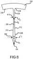
- FIG. 6is detailed view of a blade of a flexural pivot in accordance with embodiments of the present disclosure.
- FIG. 7is detailed view of a blade of a flexural pivot in accordance with other embodiments of the present disclosure.
- FIG. 8is detailed view of a blade of a flexural pivot in accordance with other embodiments of the present disclosure.
- FIG. 9is a flowchart illustrating aspects of method for providing a flexural pivot in accordance with embodiments of the present disclosure.
- FIG. 1A pivot assembly 100 incorporating a flexural pivot 104 in accordance with embodiments of the present disclosure is illustrated in FIG. 1 .
- the flexural pivot 104includes a first or base section 108 that is connected to a second or pivoted section 112 .
- the base section 108 of the flexural pivot 104can be fixed to a base member or assembly 116
- a pivoted member or assembly 120can be fixed to the pivoted section 112 .
- the flexural pivot 104allows the pivoted assembly 120 to rotate about a center axis 124 by some amount, such as +/ ⁇ 10 degrees, relative to the base assembly 116 , while preventing or inhibiting movement of the pivoted assembly 120 in any other direction relative to the base assembly 112 .
- the pivoted member or assembly 120is a mirror, such as a fast steering mirror.
- a flexural pivot 104 as disclosed hereincan be used to allow any assembly or member to be pivoted or rotated about a center axis relative to a base where the range of rotation is relatively limited.
- FIG. 2is a perspective view
- FIG. 3is an end view from a first side
- FIG. 4is an end view from a second side
- FIG. 5is a cross section of a flexural pivot 104 in accordance with embodiments of the present disclosure.
- the base section 108can be axially aligned with the pivoted section 112 .
- the pivoted section 112can be rotated relative to the base section 108 about a center or pivot axis 124 .
- the base 108 and pivoted 112 sectionsare separated by a circumferential groove 204 .
- the base 108includes a first end section 208 a
- the pivoted section 112includes a second end section 208 b .
- Each end section 208 a and 208 bis shown as featuring a substantially cylindrical exterior surface 212 a and 212 b respectively.
- the exterior surfaces 212 a and/or 212 bcan include provisions, such as threaded holes, bosses, mounting tabs, or other features to facilitate fixing the respective sections 108 and 112 to a base assembly 116 and a pivoted assembly 120 respectively.
- the first end section 208 aincludes a substantially cylindrical inner surface 216 a with a recessed portion 220 a formed therein that receives a tab 224 b that extends from the second end section 208 b .
- the second end section 208 bincludes a substantially cylindrical inner surface 216 b with a recessed portion 220 b formed therein that receives a tab 224 a that extends from the first end section 208 a into an interior volume of the second end section 208 b .
- each of the tabs 224 a and 224 b adjacent the respective recessed portions 220 a and 220 bis arcuately-shaped, to follow the curve of the respective recessed portion 220 , forming a space therebetween. Moreover, each of the tabs 224 continues the interior surface 216 of the respective end section 208 .
- each blade 232includes a first blade half 236 that extends between an interior surface 216 a of the first end section 208 a to the center axis 124 , and a second blade half 240 that extends between an interior surface 216 b of the second end section 208 b and the center axis 124 .
- the flexural pivot 104includes four blades 232 , each including a first blade half 236 a - d and a second blade half 240 a - d respectively.
- the blades 236are symmetrical about the center axis 124 .
- the blades 232extend along the center axis 124 such that they are adjacent at least a portion of the first end section 208 a and a portion of the second end section 208 b .
- the blades 232extend along the entire length of the first end section 204 a and the second end section 208 b.
- the length of the arc described by each of the tabs 224is less than 180 degrees, and is less than the length of the arc described by the recessed portions 220 .
- the tabs 224are centered in their respective recessed portions 220 when the flexural pivot 104 is in an unflexed condition. Accordingly, rotation by some amount that is no greater than the arcuate length of the gap 244 between an end of the recessed portion 220 and an edge of a tab 224 received by the recessed portion is possible in either direction around the center axis 124 .
- the gap 244can be asymmetrical.
- a gap 244can exist between an edge of a tab 224 on one side of the flexural pivot 104 , to allow rotation in a direction that would close or make that gap narrower, while the gap 244 along the opposite side of the flexural pivot can be small or non-existent while the flexural pivot 104 is in a relaxed state, such that rotation in the opposite direction is more limited than the other direction or is inhibited entirely.
- each blade 232has a first dimension or thickness T that varies with distance D from the center axis 124 .
- FIG. 6illustrates a half (e.g. a first blade half 236 ) of a blade 232 that varies in thickness with distance from the center axis 124 in accordance with embodiments of the present disclosure.
- the other halfe.g. a second blade half 240
- the blade 232mirrors e or is identical to the illustrated (e.g. the first) blade half 236 .
- each blade 232may have a first thickness T 1
- each blade 232may have a second thickness T 2
- each blade 232may be symmetrical about the center axis 124 , such that each blade half 236 and 240 of a given blade 232 may have a first thickness T 1 at the first distance from the center axis 124 and a second thickness T 2 at a second distance from the center axis 124 .
- a first 604 and second 608 surface of each of the blades 232may have the same thickness contour.
- the thinnest portion 616is between 60% and 70% of the distance between the center axis 124 and the inner surface 216 of an end section 208 .
- the first 612 and second 620 radiused portionscan have the same or different curvatures.
- the curvaturesmay have a constant radius, or can follow some other curves, such as a parabolic curve.
- the straight taper section 608can be omitted.
- each blade 232may feature selected contouring. Accordingly, the thickness of a blade 232 can be varied to form contours that follow straight lines, constant radius lines, varying radius lines, such as but not limited to parabolic lines, or combinations of lines of different configurations.
- the blade 232 sectionfeatures a first notched portion 704 at a first distance D 1 from the center axis 124 , and a second notched portion 708 at a second distance D 2 from the center axis 124 .
- the thickness T 1 of the blade 232 at the first notched portion 704may be the same as or different than the thickness T 2 of the blade 232 at the second notched portion 708 .
- the blade 232 sectionfeatures a straight taper section 712 , along which the blade 232 may have a constant thickness T 3 .
- the thickness of the blade along the tapered section 712may vary between the first notched section 704 and the second notched portion 708 .
- the thickness of the blade 232 within the straight taper section 712may decrease with distance from the center axis 124 .
- FIG. 8a detail of a blade 232 half 236 or 240 in accordance with still other embodiments of the present disclosure is depicted.
- the blade 232 sectionfeatures radiused surfaces 804 that are symmetric with one another, and that extend between an inner diameter fillet radius 808 and an outer diameter fillet radius 812 .
- the thickness T 1 of the blade 232 at a first distance D 1 from the center axis 124may equal a minimum thickness of the blade 232 .
- the minimum thickness T 1 of the blade 232and may be at a location that is between 60% in 70% of the distance between the center axis 124 and the interior surface 216 of the corresponding end section 208 .
- Embodiments of the present disclosurein which the thickness of a blade 232 varies with distance from the central axis 124 can increase the life of the flexural pivot 104 . Moreover, fatigue life can be improved, while avoiding undesired increases in rotational stiffness. In accordance with further embodiments, the rotational stiffness of the flexural pivot 104 may be decreased as compared to designs having blades 232 with a constant thickness. Moreover, such advantages can be achieved while maintaining a desired strength or load carrying capacity. In addition, the shaping of the blades 232 does not affect the cost, manufacturing process, or installation of the flexural pivot 104 .
- the various components of the flexural pivot 104are all formed from a single piece of material.
- This monolithic or integral structureis advantageous in that it avoids the need for joints, and for the need to weld, braze, bond or otherwise connect individual pieces at such joints.
- embodiments featuring four blades 232have been illustrated and described, embodiments of the present disclosure are not so limited. In particular, any number of blades 232 can be provided. Moreover, the links of the blades 232 can be varied, for instance in combination with variations in the thickness of the blades 232 , to achieve desired load carrying capacities, fatigue life, and flexibility. In accordance with further embodiments of the present disclosure, the thinnest portion of the blades 232 is about two thirds of the length of the blade from the center axis 124 typically corresponds to an area of lowest stress. This provides greater flexibility, without decreasing the load carrying capacity or the fatigue life of the blades 232 and the flexural pivot 104 incorporating the blades 232 .
- the blades 232need not be rectangular and flat when viewed in a plane encompassing the center axis 124 .
- Examples of alternate blade 232 geometriesinclude, but are not limited to, hourglass and barrel shapes.
- the blades 232can have apertures or notches.
- aspects of the blade 232 shapingcan be varied and balanced to achieve desired load capacity, fatigue life, and bending resistance properties.
- FIG. 9is a flowchart depicting aspects of a method for providing a flexural pivot 104 in accordance with embodiments of the present disclosure.
- the dimensions of the desired flexural pivot 104are determined. This can include determining a desired size of the end sections 208 , and the desired loadbearing capacity, fatigue life, centering force, and maximum angles of rotation provided by the flexural pivot 104 .
- the shape of the blades 232can be determined.
- finite element analysiscan be used to configure and optimize the shape of the blades 232 in order to optimize rotational strength, rotational stiffness, rotational fatigue life, radial strength, radial stiffness, radial fatigue life, axial strength, axial stiffness, and axial fatigue life.
- a block of material having dimensions as large or larger than the maximum outer dimensions of the desired flexural pivot 104is provided.
- the block of materialmay be selected to provide desired strength and fatigue characteristics in the completed flexural pivot 104 . Examples of suitable materials include aluminum, steel, titanium, plastic, or the like.
- machiningcan include drilling, sawing, etching or other operations.
- such operationscan include wire electrical discharge machining (EDM).
- EDMwire electrical discharge machining
- such operationscan include additive manufacturing techniques.
- an optional finishing step of surface finishing, such as acid etching, anodizing, or platingcan be performed.
- a monolithic or unitary structurein which the various components of a flexural pivot 104 , including end sections 208 and blades 232 that have varying thicknesses, are formed from a single block of material, is provided.
- a flexural pivot 104used in combination with a pivoted member or assembly 120 in the form of a mirror, such as a fast steering mirror, have been described, embodiments of the present disclosure are not so limited.
- a flexural pivot 104 in accordance with embodiments of the present disclosurecan be used as a support for any object, structure or component in which it is desirable to provide rotation about an axis, while inhibiting movement in other directions or dimensions.
- a flexural pivot 104 as disclosed hereincan provide an increased fatigue life.
- a flexural pivot 104 in accordance with embodiments of the present disclosurecan be used in applications where a relatively high frequency of oscillation or change in angle is required or desirable.
- the flexural pivot 104can also provide a self-centering force, that tends to bring the supported structure back to a neutral position relative to the base mounting structure.
Landscapes
- Engineering & Computer Science (AREA)
- General Engineering & Computer Science (AREA)
- Mechanical Engineering (AREA)
- Physics & Mathematics (AREA)
- General Physics & Mathematics (AREA)
- Optics & Photonics (AREA)
- Pivots And Pivotal Connections (AREA)
Abstract
Description
Claims (20)
Priority Applications (2)
| Application Number | Priority Date | Filing Date | Title |
|---|---|---|---|
| US16/141,593US10914339B2 (en) | 2018-09-25 | 2018-09-25 | Flexural pivot assembly with shaped blade sections |
| PCT/US2019/035723WO2020068192A1 (en) | 2018-09-25 | 2019-06-06 | Flexural pivot assembly with shaped blade sections |
Applications Claiming Priority (1)
| Application Number | Priority Date | Filing Date | Title |
|---|---|---|---|
| US16/141,593US10914339B2 (en) | 2018-09-25 | 2018-09-25 | Flexural pivot assembly with shaped blade sections |
Publications (2)
| Publication Number | Publication Date |
|---|---|
| US20200096038A1 US20200096038A1 (en) | 2020-03-26 |
| US10914339B2true US10914339B2 (en) | 2021-02-09 |
Family
ID=67003711
Family Applications (1)
| Application Number | Title | Priority Date | Filing Date |
|---|---|---|---|
| US16/141,593Active2039-02-06US10914339B2 (en) | 2018-09-25 | 2018-09-25 | Flexural pivot assembly with shaped blade sections |
Country Status (2)
| Country | Link |
|---|---|
| US (1) | US10914339B2 (en) |
| WO (1) | WO2020068192A1 (en) |
Cited By (4)
| Publication number | Priority date | Publication date | Assignee | Title |
|---|---|---|---|---|
| US11572918B2 (en)* | 2017-10-24 | 2023-02-07 | CSEM Centre Suisse d'Electronique et de Microtechnique SA—Recherche et Développement | Pivot mechanism with flexible elements for large-amplitude rotation guiding and pivot assembly comprising a plurality of said pivot mechanism |
| US12130423B1 (en) | 2020-08-12 | 2024-10-29 | Bae Systems Space & Mission Systems Inc. | Two degree-of freedom reactionless pointing and scanning system |
| US12313905B1 (en) | 2022-03-15 | 2025-05-27 | Bae Systems Space & Mission Systems Inc. | Monolithic two-axis flexure with center hole feature |
| US12320466B2 (en) | 2021-03-10 | 2025-06-03 | Bae Systems Space & Mission Systems Inc. | Systems and methods for limiting rotation of a supported object |
Citations (50)
| Publication number | Priority date | Publication date | Assignee | Title |
|---|---|---|---|---|
| US3181851A (en) | 1961-10-03 | 1965-05-04 | Bendix Corp | Flexural pivot |
| US3181918A (en) | 1962-06-29 | 1965-05-04 | Bendix Corp | Flexural pivot |
| US3252696A (en) | 1963-10-21 | 1966-05-24 | Bendix Corp | Flexural pivot device |
| US3465997A (en) | 1965-08-30 | 1969-09-09 | Wild Heerbrugg Ag | Pivotal support or mounting |
| US3807029A (en) | 1972-09-05 | 1974-04-30 | Bendix Corp | Method of making a flexural pivot |
| US3811665A (en) | 1972-09-05 | 1974-05-21 | Bendix Corp | Flexural pivot with diaphragm means |
| US3813089A (en) | 1972-09-08 | 1974-05-28 | Bendix Corp | Eccentric flexural pivot |
| US3825992A (en) | 1972-09-08 | 1974-07-30 | Bendix Corp | Method of making an eccentric flexural pivot |
| US4261211A (en) | 1976-11-24 | 1981-04-14 | Anschutz & Co. G.M.B.H. | Flexure joint, particularly for connecting a gyroscope to its driving shaft |
| US4327527A (en) | 1980-06-30 | 1982-05-04 | The Bendix Corporation | Apparatus and method for adjusting the torsional output of a flexible pivot |
| DE3241373A1 (en) | 1982-11-09 | 1984-05-10 | Anschütz & Co GmbH, 2300 Kiel | SPRING JOINT |
| US4533100A (en) | 1981-04-03 | 1985-08-06 | R.E.O.S.C. (Recherches Et Etudes D'optique Et De Sciences Connexes) | Mounting device for supporting a component, especially a mirror or an antenna reflector in a spacecraft |
| US4637596A (en)* | 1985-10-04 | 1987-01-20 | Allied Corporation | Structural core pivot |
| US4655629A (en)* | 1985-02-19 | 1987-04-07 | Westinghouse Electric Corp. | Flexural pivot device and method for assembling same |
| US4678295A (en) | 1985-04-05 | 1987-07-07 | Magna International Inc | Memory positioning system for remote control rear-view mirror |
| US4770522A (en) | 1987-11-02 | 1988-09-13 | Siegel-Robert, Inc. | Automobile mirror position sensor and adjuster assembly |
| US4802720A (en) | 1987-06-30 | 1989-02-07 | Paulsen Dean R | Flexural pivot |
| US4802784A (en) | 1988-03-11 | 1989-02-07 | Santa Barbara Research Center | Bi-flex pivot |
| US4812072A (en) | 1988-03-11 | 1989-03-14 | Santa Barbara Research Center | Torsion structural pivot |
| US4825713A (en) | 1987-09-30 | 1989-05-02 | Honeywell, Inc. | Monolithic suspension assembly using cross flexure pivots |
| EP0348845A2 (en) | 1988-06-25 | 1990-01-03 | Nec Home Electronics, Ltd. | An objective lens supporting mechanism for use in an objective lens actuator of an optical head |
| US4919382A (en) | 1988-09-14 | 1990-04-24 | The United States Of America As Represented By The Secretary Of The Navy | Multi-post yoke gimbal |
| US4919993A (en)* | 1989-02-27 | 1990-04-24 | Sundstrand Data Control, Inc. | Flexures and method for creating flexures in a wafer |
| US4997123A (en) | 1990-05-31 | 1991-03-05 | Lucas Aerospace Power Transmission Corp. | Multi-piece flexural pivot |
| US5283682A (en) | 1992-10-06 | 1994-02-01 | Ball Corporation | Reactionless scanning and positioning system |
| US5521740A (en) | 1995-07-11 | 1996-05-28 | General Scanning, Inc. | Resonant optical scanner |
| US5529277A (en) | 1994-09-20 | 1996-06-25 | Ball Corporation | Suspension system having two degrees of rotational freedom |
| US5620169A (en) | 1994-11-02 | 1997-04-15 | Ball Corporation | Rotary mount integral flexural pivot with blades which are integrally interconnected at the blade intersection |
| US5703732A (en) | 1995-01-17 | 1997-12-30 | Lowell Engineering Corporation | Exterior mirror with indexing and control pivoting |
| EP1013949A1 (en) | 1998-12-17 | 2000-06-28 | Sysmelec SA | Flexible pivot with large pivot angle and elevated rigidity |
| US6275624B1 (en) | 1999-12-03 | 2001-08-14 | Optical Coating Laboratory, Inc. | Optical switch with flexure pivot |
| US6365252B1 (en)* | 1999-04-16 | 2002-04-02 | Lucas Aerospace Power Transmission | Multi-piece flexural pivot |
| US6972885B2 (en) | 2003-06-24 | 2005-12-06 | Drs Sensors & Targeting Systems, Inc. | Precision mirror displacement assembly |
| EP1887398A1 (en) | 2006-08-08 | 2008-02-13 | Selex Sensors and Airborne Systems Limited | Mirror mount |
| US7354170B2 (en) | 2005-02-14 | 2008-04-08 | Kabushiki Kaisha Honda Lock | Vehicular mirror having tilt angle detection rod with swing axis |
| US7515385B1 (en)* | 2004-02-05 | 2009-04-07 | Maxtor Corporation | Band pivot bearing |
| US20100208322A1 (en) | 2009-02-17 | 2010-08-19 | Spudnik, Inc. | Flexure Actuator |
| US8556533B2 (en)* | 2011-11-21 | 2013-10-15 | Raytheon Company | Multi-stage flexural pivot |
| US8702337B2 (en)* | 2011-02-18 | 2014-04-22 | Riverhawk Company | Lamellar rotational flexure pivot |
| US8708593B2 (en)* | 2010-02-04 | 2014-04-29 | Eric M. Stratton | Cross-flexural pivot |
| US20140208848A1 (en) | 2011-03-31 | 2014-07-31 | Ramot At Tel-Aviv University Ltd. | Compliant structures with time-varying moment of inertia |
| US9212691B2 (en)* | 2012-05-16 | 2015-12-15 | C-Flex Bearing Co., Inc. | Cross blade flexure pivot and methods of use thereof |
| US9354422B1 (en) | 2013-07-01 | 2016-05-31 | Ball Aerospace & Technologies Corp. | High acceleration actuator |
| US9612436B1 (en) | 2014-08-12 | 2017-04-04 | Ball Aerospace & Technologies Corp. | High-speed scanner-tracker |
| US20180196257A1 (en) | 2017-01-04 | 2018-07-12 | Ball Aerospace & Technologies Corp. | Cross flexure suspension |
| US20180252261A1 (en)* | 2017-03-02 | 2018-09-06 | Raytheon Company | Flexural Pivot |
| US20180252260A1 (en)* | 2017-03-02 | 2018-09-06 | Raytheon Company | Flexural Pivot |
| US20190120287A1 (en)* | 2017-10-24 | 2019-04-25 | Csem Centre Suisse D'electronique Et De Microtechnique Sa - Recherche Et Developpement | Pivot mechanism with flexible elements for large-amplitude rotation guiding and pivot assembly comprising a plurality of said pivot mechanism |
| US10443649B2 (en)* | 2017-01-24 | 2019-10-15 | Raytheon Company | Flexural pivot |
| US20200008827A1 (en)* | 2016-09-14 | 2020-01-09 | Intuitive Surgical Operations, Inc. | Joint assemblies with cross-axis flexural pivots |
- 2018
- 2018-09-25USUS16/141,593patent/US10914339B2/enactiveActive
- 2019
- 2019-06-06WOPCT/US2019/035723patent/WO2020068192A1/ennot_activeCeased
Patent Citations (50)
| Publication number | Priority date | Publication date | Assignee | Title |
|---|---|---|---|---|
| US3181851A (en) | 1961-10-03 | 1965-05-04 | Bendix Corp | Flexural pivot |
| US3181918A (en) | 1962-06-29 | 1965-05-04 | Bendix Corp | Flexural pivot |
| US3252696A (en) | 1963-10-21 | 1966-05-24 | Bendix Corp | Flexural pivot device |
| US3465997A (en) | 1965-08-30 | 1969-09-09 | Wild Heerbrugg Ag | Pivotal support or mounting |
| US3807029A (en) | 1972-09-05 | 1974-04-30 | Bendix Corp | Method of making a flexural pivot |
| US3811665A (en) | 1972-09-05 | 1974-05-21 | Bendix Corp | Flexural pivot with diaphragm means |
| US3813089A (en) | 1972-09-08 | 1974-05-28 | Bendix Corp | Eccentric flexural pivot |
| US3825992A (en) | 1972-09-08 | 1974-07-30 | Bendix Corp | Method of making an eccentric flexural pivot |
| US4261211A (en) | 1976-11-24 | 1981-04-14 | Anschutz & Co. G.M.B.H. | Flexure joint, particularly for connecting a gyroscope to its driving shaft |
| US4327527A (en) | 1980-06-30 | 1982-05-04 | The Bendix Corporation | Apparatus and method for adjusting the torsional output of a flexible pivot |
| US4533100A (en) | 1981-04-03 | 1985-08-06 | R.E.O.S.C. (Recherches Et Etudes D'optique Et De Sciences Connexes) | Mounting device for supporting a component, especially a mirror or an antenna reflector in a spacecraft |
| DE3241373A1 (en) | 1982-11-09 | 1984-05-10 | Anschütz & Co GmbH, 2300 Kiel | SPRING JOINT |
| US4655629A (en)* | 1985-02-19 | 1987-04-07 | Westinghouse Electric Corp. | Flexural pivot device and method for assembling same |
| US4678295A (en) | 1985-04-05 | 1987-07-07 | Magna International Inc | Memory positioning system for remote control rear-view mirror |
| US4637596A (en)* | 1985-10-04 | 1987-01-20 | Allied Corporation | Structural core pivot |
| US4802720A (en) | 1987-06-30 | 1989-02-07 | Paulsen Dean R | Flexural pivot |
| US4825713A (en) | 1987-09-30 | 1989-05-02 | Honeywell, Inc. | Monolithic suspension assembly using cross flexure pivots |
| US4770522A (en) | 1987-11-02 | 1988-09-13 | Siegel-Robert, Inc. | Automobile mirror position sensor and adjuster assembly |
| US4802784A (en) | 1988-03-11 | 1989-02-07 | Santa Barbara Research Center | Bi-flex pivot |
| US4812072A (en) | 1988-03-11 | 1989-03-14 | Santa Barbara Research Center | Torsion structural pivot |
| EP0348845A2 (en) | 1988-06-25 | 1990-01-03 | Nec Home Electronics, Ltd. | An objective lens supporting mechanism for use in an objective lens actuator of an optical head |
| US4919382A (en) | 1988-09-14 | 1990-04-24 | The United States Of America As Represented By The Secretary Of The Navy | Multi-post yoke gimbal |
| US4919993A (en)* | 1989-02-27 | 1990-04-24 | Sundstrand Data Control, Inc. | Flexures and method for creating flexures in a wafer |
| US4997123A (en) | 1990-05-31 | 1991-03-05 | Lucas Aerospace Power Transmission Corp. | Multi-piece flexural pivot |
| US5283682A (en) | 1992-10-06 | 1994-02-01 | Ball Corporation | Reactionless scanning and positioning system |
| US5529277A (en) | 1994-09-20 | 1996-06-25 | Ball Corporation | Suspension system having two degrees of rotational freedom |
| US5620169A (en) | 1994-11-02 | 1997-04-15 | Ball Corporation | Rotary mount integral flexural pivot with blades which are integrally interconnected at the blade intersection |
| US5703732A (en) | 1995-01-17 | 1997-12-30 | Lowell Engineering Corporation | Exterior mirror with indexing and control pivoting |
| US5521740A (en) | 1995-07-11 | 1996-05-28 | General Scanning, Inc. | Resonant optical scanner |
| EP1013949A1 (en) | 1998-12-17 | 2000-06-28 | Sysmelec SA | Flexible pivot with large pivot angle and elevated rigidity |
| US6365252B1 (en)* | 1999-04-16 | 2002-04-02 | Lucas Aerospace Power Transmission | Multi-piece flexural pivot |
| US6275624B1 (en) | 1999-12-03 | 2001-08-14 | Optical Coating Laboratory, Inc. | Optical switch with flexure pivot |
| US6972885B2 (en) | 2003-06-24 | 2005-12-06 | Drs Sensors & Targeting Systems, Inc. | Precision mirror displacement assembly |
| US7515385B1 (en)* | 2004-02-05 | 2009-04-07 | Maxtor Corporation | Band pivot bearing |
| US7354170B2 (en) | 2005-02-14 | 2008-04-08 | Kabushiki Kaisha Honda Lock | Vehicular mirror having tilt angle detection rod with swing axis |
| EP1887398A1 (en) | 2006-08-08 | 2008-02-13 | Selex Sensors and Airborne Systems Limited | Mirror mount |
| US20100208322A1 (en) | 2009-02-17 | 2010-08-19 | Spudnik, Inc. | Flexure Actuator |
| US8708593B2 (en)* | 2010-02-04 | 2014-04-29 | Eric M. Stratton | Cross-flexural pivot |
| US8702337B2 (en)* | 2011-02-18 | 2014-04-22 | Riverhawk Company | Lamellar rotational flexure pivot |
| US20140208848A1 (en) | 2011-03-31 | 2014-07-31 | Ramot At Tel-Aviv University Ltd. | Compliant structures with time-varying moment of inertia |
| US8556533B2 (en)* | 2011-11-21 | 2013-10-15 | Raytheon Company | Multi-stage flexural pivot |
| US9212691B2 (en)* | 2012-05-16 | 2015-12-15 | C-Flex Bearing Co., Inc. | Cross blade flexure pivot and methods of use thereof |
| US9354422B1 (en) | 2013-07-01 | 2016-05-31 | Ball Aerospace & Technologies Corp. | High acceleration actuator |
| US9612436B1 (en) | 2014-08-12 | 2017-04-04 | Ball Aerospace & Technologies Corp. | High-speed scanner-tracker |
| US20200008827A1 (en)* | 2016-09-14 | 2020-01-09 | Intuitive Surgical Operations, Inc. | Joint assemblies with cross-axis flexural pivots |
| US20180196257A1 (en) | 2017-01-04 | 2018-07-12 | Ball Aerospace & Technologies Corp. | Cross flexure suspension |
| US10443649B2 (en)* | 2017-01-24 | 2019-10-15 | Raytheon Company | Flexural pivot |
| US20180252261A1 (en)* | 2017-03-02 | 2018-09-06 | Raytheon Company | Flexural Pivot |
| US20180252260A1 (en)* | 2017-03-02 | 2018-09-06 | Raytheon Company | Flexural Pivot |
| US20190120287A1 (en)* | 2017-10-24 | 2019-04-25 | Csem Centre Suisse D'electronique Et De Microtechnique Sa - Recherche Et Developpement | Pivot mechanism with flexible elements for large-amplitude rotation guiding and pivot assembly comprising a plurality of said pivot mechanism |
Non-Patent Citations (2)
| Title |
|---|
| International Search Report and Written Opinion for International (PCT) Patent Application No. PCT/US2019/035723, dated Sep. 24, 2019 17 pages. |
| Markovic et al. "Characterization of cross-spring pivots for micropositioning applications," Proceedings of SPIE, Smart Sensors, Actuators, and MEMS VII; and Cyber Physical Systems, May 2015, vol. 9517, 951727, 8 pages. |
Cited By (4)
| Publication number | Priority date | Publication date | Assignee | Title |
|---|---|---|---|---|
| US11572918B2 (en)* | 2017-10-24 | 2023-02-07 | CSEM Centre Suisse d'Electronique et de Microtechnique SA—Recherche et Développement | Pivot mechanism with flexible elements for large-amplitude rotation guiding and pivot assembly comprising a plurality of said pivot mechanism |
| US12130423B1 (en) | 2020-08-12 | 2024-10-29 | Bae Systems Space & Mission Systems Inc. | Two degree-of freedom reactionless pointing and scanning system |
| US12320466B2 (en) | 2021-03-10 | 2025-06-03 | Bae Systems Space & Mission Systems Inc. | Systems and methods for limiting rotation of a supported object |
| US12313905B1 (en) | 2022-03-15 | 2025-05-27 | Bae Systems Space & Mission Systems Inc. | Monolithic two-axis flexure with center hole feature |
Also Published As
| Publication number | Publication date |
|---|---|
| US20200096038A1 (en) | 2020-03-26 |
| WO2020068192A1 (en) | 2020-04-02 |
Similar Documents
| Publication | Publication Date | Title |
|---|---|---|
| US10914339B2 (en) | Flexural pivot assembly with shaped blade sections | |
| US5620169A (en) | Rotary mount integral flexural pivot with blades which are integrally interconnected at the blade intersection | |
| US10598924B2 (en) | Cross flexure suspension system | |
| US3181851A (en) | Flexural pivot | |
| US20180209475A1 (en) | Flexural Pivot | |
| US11571940B2 (en) | Chassis control arm and method for the production of a chassis control arm | |
| CA2678435C (en) | Flexure with elongated openings | |
| JPH01503399A (en) | flexible coupling | |
| US7832880B2 (en) | Mirror mount having plural flexure elements | |
| JP6464198B2 (en) | Tolerance ring | |
| US6170989B1 (en) | Modular support structure for hydrodynamic bearing | |
| US11143231B2 (en) | Blade flexure assembly with replaceable elements | |
| US9684148B2 (en) | Primary mirror mount assembly and method | |
| CN115220174B (en) | Integrated opening flexible supporting structure for supporting reflector | |
| WO2020207751A1 (en) | A thread former | |
| EP2660487B1 (en) | Bearing sump with bi-directional stiffness | |
| KR20070032918A (en) | Shaft coupling | |
| US12385521B1 (en) | Flexure assembly | |
| CN113048193B (en) | Balance shaft with reduced mass and inertia | |
| CN115319270B (en) | Blade fixing device for linear friction welding of blisk | |
| CN119667890A (en) | An infrared and visible light common aperture reflector structure | |
| WO2025156095A1 (en) | Supporting apparatus for use with rotor and corresponding rotor, electric motor and generator | |
| JPS61105317A (en) | coil spring | |
| CN120083747B (en) | A rigid connector for mechanically connecting a first component to a second component | |
| CN212429530U (en) | Self-adaptive adjustable tilting pad lining part |
Legal Events
| Date | Code | Title | Description |
|---|---|---|---|
| AS | Assignment | Owner name:BALL AEROSPACE & TECHNOLOGIES CORP., COLORADO Free format text:ASSIGNMENT OF ASSIGNORS INTEREST;ASSIGNOR:WARDEN, ROBERT M.;REEL/FRAME:046967/0436 Effective date:20180925 | |
| FEPP | Fee payment procedure | Free format text:ENTITY STATUS SET TO UNDISCOUNTED (ORIGINAL EVENT CODE: BIG.); ENTITY STATUS OF PATENT OWNER: LARGE ENTITY | |
| STPP | Information on status: patent application and granting procedure in general | Free format text:NON FINAL ACTION MAILED | |
| STPP | Information on status: patent application and granting procedure in general | Free format text:RESPONSE TO NON-FINAL OFFICE ACTION ENTERED AND FORWARDED TO EXAMINER | |
| STPP | Information on status: patent application and granting procedure in general | Free format text:NOTICE OF ALLOWANCE MAILED -- APPLICATION RECEIVED IN OFFICE OF PUBLICATIONS | |
| STPP | Information on status: patent application and granting procedure in general | Free format text:PUBLICATIONS -- ISSUE FEE PAYMENT RECEIVED | |
| STPP | Information on status: patent application and granting procedure in general | Free format text:AWAITING TC RESP, ISSUE FEE PAYMENT VERIFIED | |
| STPP | Information on status: patent application and granting procedure in general | Free format text:PUBLICATIONS -- ISSUE FEE PAYMENT VERIFIED | |
| STCF | Information on status: patent grant | Free format text:PATENTED CASE | |
| AS | Assignment | Owner name:BAE SYSTEMS SPACE & MISSION SYSTEMS INC., COLORADO Free format text:CHANGE OF NAME;ASSIGNOR:BALL AEROSPACE & TECHNOLOGIES CORP.;REEL/FRAME:067134/0901 Effective date:20240223 | |
| MAFP | Maintenance fee payment | Free format text:PAYMENT OF MAINTENANCE FEE, 4TH YEAR, LARGE ENTITY (ORIGINAL EVENT CODE: M1551); ENTITY STATUS OF PATENT OWNER: LARGE ENTITY Year of fee payment:4 |