US10914315B2 - Gas turbine engine airfoil - Google Patents
Gas turbine engine airfoilDownload PDFInfo
- Publication number
- US10914315B2 US10914315B2US16/681,187US201916681187AUS10914315B2US 10914315 B2US10914315 B2US 10914315B2US 201916681187 AUS201916681187 AUS 201916681187AUS 10914315 B2US10914315 B2US 10914315B2
- Authority
- US
- United States
- Prior art keywords
- span
- section
- gas turbine
- turbine engine
- edge angle
- Prior art date
- Legal status (The legal status is an assumption and is not a legal conclusion. Google has not performed a legal analysis and makes no representation as to the accuracy of the status listed.)
- Active
Links
Images


Classifications
- F—MECHANICAL ENGINEERING; LIGHTING; HEATING; WEAPONS; BLASTING
- F01—MACHINES OR ENGINES IN GENERAL; ENGINE PLANTS IN GENERAL; STEAM ENGINES
- F01D—NON-POSITIVE DISPLACEMENT MACHINES OR ENGINES, e.g. STEAM TURBINES
- F01D5/00—Blades; Blade-carrying members; Heating, heat-insulating, cooling or antivibration means on the blades or the members
- F01D5/12—Blades
- F01D5/14—Form or construction
- F01D5/141—Shape, i.e. outer, aerodynamic form
- F—MECHANICAL ENGINEERING; LIGHTING; HEATING; WEAPONS; BLASTING
- F04—POSITIVE - DISPLACEMENT MACHINES FOR LIQUIDS; PUMPS FOR LIQUIDS OR ELASTIC FLUIDS
- F04D—NON-POSITIVE-DISPLACEMENT PUMPS
- F04D29/00—Details, component parts, or accessories
- F04D29/26—Rotors specially for elastic fluids
- F04D29/32—Rotors specially for elastic fluids for axial flow pumps
- F04D29/38—Blades
- F04D29/384—Blades characterised by form
- F—MECHANICAL ENGINEERING; LIGHTING; HEATING; WEAPONS; BLASTING
- F01—MACHINES OR ENGINES IN GENERAL; ENGINE PLANTS IN GENERAL; STEAM ENGINES
- F01D—NON-POSITIVE DISPLACEMENT MACHINES OR ENGINES, e.g. STEAM TURBINES
- F01D9/00—Stators
- F01D9/02—Nozzles; Nozzle boxes; Stator blades; Guide conduits, e.g. individual nozzles
- F01D9/04—Nozzles; Nozzle boxes; Stator blades; Guide conduits, e.g. individual nozzles forming ring or sector
- F01D9/041—Nozzles; Nozzle boxes; Stator blades; Guide conduits, e.g. individual nozzles forming ring or sector using blades
- F—MECHANICAL ENGINEERING; LIGHTING; HEATING; WEAPONS; BLASTING
- F02—COMBUSTION ENGINES; HOT-GAS OR COMBUSTION-PRODUCT ENGINE PLANTS
- F02C—GAS-TURBINE PLANTS; AIR INTAKES FOR JET-PROPULSION PLANTS; CONTROLLING FUEL SUPPLY IN AIR-BREATHING JET-PROPULSION PLANTS
- F02C3/00—Gas-turbine plants characterised by the use of combustion products as the working fluid
- F02C3/04—Gas-turbine plants characterised by the use of combustion products as the working fluid having a turbine driving a compressor
- F—MECHANICAL ENGINEERING; LIGHTING; HEATING; WEAPONS; BLASTING
- F04—POSITIVE - DISPLACEMENT MACHINES FOR LIQUIDS; PUMPS FOR LIQUIDS OR ELASTIC FLUIDS
- F04D—NON-POSITIVE-DISPLACEMENT PUMPS
- F04D29/00—Details, component parts, or accessories
- F04D29/26—Rotors specially for elastic fluids
- F04D29/32—Rotors specially for elastic fluids for axial flow pumps
- F04D29/321—Rotors specially for elastic fluids for axial flow pumps for axial flow compressors
- F04D29/324—Blades
- F—MECHANICAL ENGINEERING; LIGHTING; HEATING; WEAPONS; BLASTING
- F04—POSITIVE - DISPLACEMENT MACHINES FOR LIQUIDS; PUMPS FOR LIQUIDS OR ELASTIC FLUIDS
- F04D—NON-POSITIVE-DISPLACEMENT PUMPS
- F04D29/00—Details, component parts, or accessories
- F04D29/26—Rotors specially for elastic fluids
- F04D29/32—Rotors specially for elastic fluids for axial flow pumps
- F04D29/325—Rotors specially for elastic fluids for axial flow pumps for axial flow fans
- F—MECHANICAL ENGINEERING; LIGHTING; HEATING; WEAPONS; BLASTING
- F04—POSITIVE - DISPLACEMENT MACHINES FOR LIQUIDS; PUMPS FOR LIQUIDS OR ELASTIC FLUIDS
- F04D—NON-POSITIVE-DISPLACEMENT PUMPS
- F04D29/00—Details, component parts, or accessories
- F04D29/40—Casings; Connections of working fluid
- F04D29/52—Casings; Connections of working fluid for axial pumps
- F04D29/54—Fluid-guiding means, e.g. diffusers
- F04D29/541—Specially adapted for elastic fluid pumps
- F04D29/542—Bladed diffusers
- F04D29/544—Blade shapes
- F—MECHANICAL ENGINEERING; LIGHTING; HEATING; WEAPONS; BLASTING
- F04—POSITIVE - DISPLACEMENT MACHINES FOR LIQUIDS; PUMPS FOR LIQUIDS OR ELASTIC FLUIDS
- F04D—NON-POSITIVE-DISPLACEMENT PUMPS
- F04D29/00—Details, component parts, or accessories
- F04D29/40—Casings; Connections of working fluid
- F04D29/52—Casings; Connections of working fluid for axial pumps
- F04D29/54—Fluid-guiding means, e.g. diffusers
- F04D29/56—Fluid-guiding means, e.g. diffusers adjustable
- F04D29/563—Fluid-guiding means, e.g. diffusers adjustable specially adapted for elastic fluid pumps
- F—MECHANICAL ENGINEERING; LIGHTING; HEATING; WEAPONS; BLASTING
- F05—INDEXING SCHEMES RELATING TO ENGINES OR PUMPS IN VARIOUS SUBCLASSES OF CLASSES F01-F04
- F05D—INDEXING SCHEME FOR ASPECTS RELATING TO NON-POSITIVE-DISPLACEMENT MACHINES OR ENGINES, GAS-TURBINES OR JET-PROPULSION PLANTS
- F05D2220/00—Application
- F05D2220/30—Application in turbines
- F05D2220/32—Application in turbines in gas turbines
- F—MECHANICAL ENGINEERING; LIGHTING; HEATING; WEAPONS; BLASTING
- F05—INDEXING SCHEMES RELATING TO ENGINES OR PUMPS IN VARIOUS SUBCLASSES OF CLASSES F01-F04
- F05D—INDEXING SCHEME FOR ASPECTS RELATING TO NON-POSITIVE-DISPLACEMENT MACHINES OR ENGINES, GAS-TURBINES OR JET-PROPULSION PLANTS
- F05D2240/00—Components
- F05D2240/10—Stators
- F05D2240/12—Fluid guiding means, e.g. vanes
- F05D2240/121—Fluid guiding means, e.g. vanes related to the leading edge of a stator vane
- F—MECHANICAL ENGINEERING; LIGHTING; HEATING; WEAPONS; BLASTING
- F05—INDEXING SCHEMES RELATING TO ENGINES OR PUMPS IN VARIOUS SUBCLASSES OF CLASSES F01-F04
- F05D—INDEXING SCHEME FOR ASPECTS RELATING TO NON-POSITIVE-DISPLACEMENT MACHINES OR ENGINES, GAS-TURBINES OR JET-PROPULSION PLANTS
- F05D2240/00—Components
- F05D2240/20—Rotors
- F05D2240/30—Characteristics of rotor blades, i.e. of any element transforming dynamic fluid energy to or from rotational energy and being attached to a rotor
- F05D2240/303—Characteristics of rotor blades, i.e. of any element transforming dynamic fluid energy to or from rotational energy and being attached to a rotor related to the leading edge of a rotor blade
- F—MECHANICAL ENGINEERING; LIGHTING; HEATING; WEAPONS; BLASTING
- F05—INDEXING SCHEMES RELATING TO ENGINES OR PUMPS IN VARIOUS SUBCLASSES OF CLASSES F01-F04
- F05D—INDEXING SCHEME FOR ASPECTS RELATING TO NON-POSITIVE-DISPLACEMENT MACHINES OR ENGINES, GAS-TURBINES OR JET-PROPULSION PLANTS
- F05D2240/00—Components
- F05D2240/35—Combustors or associated equipment
- Y—GENERAL TAGGING OF NEW TECHNOLOGICAL DEVELOPMENTS; GENERAL TAGGING OF CROSS-SECTIONAL TECHNOLOGIES SPANNING OVER SEVERAL SECTIONS OF THE IPC; TECHNICAL SUBJECTS COVERED BY FORMER USPC CROSS-REFERENCE ART COLLECTIONS [XRACs] AND DIGESTS
- Y02—TECHNOLOGIES OR APPLICATIONS FOR MITIGATION OR ADAPTATION AGAINST CLIMATE CHANGE
- Y02T—CLIMATE CHANGE MITIGATION TECHNOLOGIES RELATED TO TRANSPORTATION
- Y02T50/00—Aeronautics or air transport
- Y02T50/60—Efficient propulsion technologies, e.g. for aircraft
Definitions
- This disclosurerelates to gas turbine engine airfoils. More particularly the disclosure relates to airfoil leading and trailing edge angles in, for example, a gas turbine engine compressor.
- a turbine enginesuch as a gas turbine engine typically includes a fan section, a compressor section, a combustor section and a turbine section. Air entering the compressor section is compressed and delivered into the combustor section where it is mixed with fuel and ignited to generate a high-speed exhaust gas flow. The high-speed exhaust gas flow expands through the turbine section to drive the compressor and the fan section.
- the compressor sectiontypically includes at least low and high pressure compressors, and the turbine section includes at least low and high pressure turbines.
- Direct drive gas turbine enginesinclude a fan section that is driven directly by one of the turbine shafts. Rotor blades in the fan section and a low pressure compressor of the compressor section of direct drive engines rotate in the same direction.
- Gas turbine engineshave been proposed in which a geared architecture is arranged between the fan section and at least some turbines in the turbine section.
- the geared architectureenables the associated compressor of the compressor section to be driven at much higher rotational speeds, improving overall efficiency of the engine.
- the propulsive efficiency of a gas turbine enginedepends on many different factors, such as the design of the engine and the resulting performance debits on the fan that propels the engine and the compressor section downstream from the fan. Physical interaction between the fan and the air causes downstream turbulence and further losses. Although some basic principles behind such losses are understood, identifying and changing appropriate design factors to reduce such losses for a given engine architecture has proven to be a complex and elusive task.
- Prior compressor airfoil geometriesmay not be suitable for the compressor section of gas turbine engines using a geared architecture, since the significantly different speeds of the compressor changes the desired aerodynamics of the airfoils within the compressor section.
- Counter-rotating fan and compressor bladeswhich may be used in geared architecture engines, also present design challenges.
- an airfoil of a turbine engineincludes pressure and suction sides that extend in a radial direction from a 0% span position to a 100% span position.
- the airfoilhas a relationship between a leading edge angle and span position that defines a curve with at least one of a decreasingly negative slope or a positive slope from 80% span to 100% span.
- the curvehas a negative slope from 0% span to 20% span.
- the curvehas less than a 40° leading edge angle from 20% span to 50% span.
- the curvehas a slope that is generally constant from 20% span to 70% span.
- the airfoilhas a relationship between a trailing edge angle and span position that defines another curve with a non-positive slope from 90% span to 100% span.
- the other curveis generally linear with a trailing edge angle of less than 75° at 0% span and a trailing edge angle of less than 40° at 100% span.
- a gas turbine enginein another exemplary embodiment, includes a combustor section arranged between a compressor section and a turbine section.
- a fan sectionhas an array of twenty-six or fewer fan blades.
- the fan sectionhas a fan pressure ratio of less than 1.55.
- a geared architecturecouples the fan section to the turbine section or the compressor section.
- An airfoilincludes pressure and suction sides that extend in a radial direction from a 0% span position to a 100% span position.
- the airfoilhas a relationship between a leading edge angle and span position that defines a curve with at least one of a decreasingly negative slope or a positive slope from 80% span to 100% span.
- the airfoilis arranged in the compressor section.
- the compressor sectionincludes at least a low pressure compressor and a high pressure compressor.
- the high pressure compressoris arranged immediately upstream of the combustor section.
- the airfoilis provided in a compressor outside the high pressure compressor section.
- the low pressure compressoris counter-rotating relative to the fan blades.
- the gas turbine engineis a two-spool configuration.
- the low pressure compressoris immediately downstream from the fan section.
- the airfoilis rotatable relative to an engine static structure.
- the curvehas a negative slope from 0% span to 20% span.
- the curvehas less than a 40° leading edge angle from 20% span to 50% span.
- the curvehas a slope that is generally constant from 20% span to 70% span.
- the airfoilhas a relationship between a trailing edge angle and span position that includes another curve with a non-positive slope from 90% span to 100% span.
- the other curveis generally linear with a trailing edge angle of less than 75° at 0% span and a trailing edge angle of less than 40° at 100% span.
- an airfoil of a turbine engineincludes pressure and suction sides that extend in a radial direction from a 0% span position to a 100% span position.
- the airfoilhas a relationship between a trailing edge angle and span position that defines a curve with a non-positive slope from 90% span to 100% span.
- the curveis generally linear with a trailing edge angle of less than 85° at 0% span and a trailing edge angle of less than 55° at 100% span.
- the trailing edge angleis less than 75° at 0% span and a trailing edge angle is less than 40° at 100% span.
- the trailing edge angleis less than 35° at 100% span.
- the airfoilhas a relationship between a leading edge angle and span position that includes another curve with at least one of a decreasingly negative slope or a positive slope from 80% span to 100% span.
- the other curvehas a negative slope from 0% span to 20% span.
- the other curvehas less than a 40° leading edge angle from 20% span to 50% span.
- the other curvehas a slope that is generally constant from 20% span to 70% span.
- a gas turbine enginein another exemplary embodiment, includes a combustor section that is arranged between a compressor section and a turbine section.
- a fan sectionhas an array of twenty-six or fewer fan blades.
- the fan sectionhas a fan pressure ratio of less than 1.55.
- a geared architecturecouples the fan section to the turbine section or the compressor section.
- An airfoilincludes pressure and suction sides that extend in a radial direction from a 0% span position to a 100% span position.
- the airfoilhas a relationship between a trailing edge angle and span position that includes a curve with a non-positive slope from 90% span to 100% span.
- the airfoilis arranged in the compressor section.
- the compressor sectionincludes at least a low pressure compressor and a high pressure compressor.
- the high pressure compressoris arranged immediately upstream of the combustor section.
- the airfoilis provided in a compressor outside the high pressure compressor section.
- the low pressure compressoris counter-rotating relative to the fan blades.
- the gas turbine engineis a two-spool configuration.
- the low pressure compressoris immediately downstream from the fan section.
- the airfoilis rotatable relative to an engine static structure.
- the curveis generally linear with a trailing edge angle of less than 85° at 0% span and a trailing edge angle of less than 55° at 100% span.
- the trailing edge angleis less than 75° at 0% span and a trailing edge angle is less than 40° at 100% span.
- the trailing edge angleis less than 35° at 100% span.
- the airfoilhas a relationship between a leading edge angle and span position that includes another curve with at least one of a decreasingly negative slope or a positive slope from 80% span to 100% span.
- the other curvehas a negative slope from 0% span to 20% span.
- the other curvehas less than a 40° leading edge angle from 20% span to 50% span.
- the other curvehas a slope that is generally constant from 20% span to 70% span.
- FIG. 1schematically illustrates a gas turbine engine embodiment with a geared architecture.
- FIG. 2schematically illustrates a low pressure compressor section of the gas turbine engine of FIG. 1 .
- FIG. 3is a schematic view of airfoil span positions.
- FIG. 4is a schematic view of a cross-section of an airfoil sectioned at a particular span position and depicting directional indicators.
- FIG. 5is a schematic view of an airfoil depicting leading and trailing edge angles.
- FIG. 6graphically depicts curves for several example airfoil leading edge angles relative to span, including two prior art curves and several inventive curves according to this disclosure.
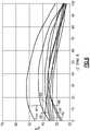
- FIG. 7graphically depicts curves for several example airfoil trailing edge angles relative to span, including two prior art curves and several inventive curves according to this disclosure.
- FIG. 1schematically illustrates a gas turbine engine 20 .
- the gas turbine engine 20is disclosed herein as a two-spool turbofan that generally incorporates a fan section 22 , a compressor section 24 , a combustor section 26 and a turbine section 28 .
- Alternative enginesmight include an augmenter section (not shown) among other systems or features.
- the fan section 22drives air along a bypass flow path B in a bypass duct defined within a nacelle 15
- the compressor section 24drives air along a core flow path C for compression and communication into the combustor section 26 then expansion through the turbine section 28 .
- the concepts described hereinare not limited to use with two-spool turbofans as the teachings may be applied to other types of turbine engines including three-spool architectures. That is, the disclosed airfoils may be used for engine configurations such as, for example, direct fan drives, or two- or three-spool engines with a speed change mechanism coupling the fan with a compressor or a turbine sections.
- the exemplary engine 20generally includes a low speed spool 30 and a high speed spool 32 mounted for rotation about an engine central longitudinal axis X relative to an engine static structure 36 via several bearing systems 38 . It should be understood that various bearing systems 38 at various locations may alternatively or additionally be provided, and the location of bearing systems 38 may be varied as appropriate to the application.
- the low speed spool 30generally includes an inner shaft 40 that interconnects a fan 42 , a first (or low) pressure compressor 44 and a first (or low) pressure turbine 46 .
- the inner shaft 40is connected to the fan 42 through a speed change mechanism, which in exemplary gas turbine engine 20 is illustrated as a geared architecture 48 to drive the fan 42 at a lower speed than the low speed spool 30 .
- the high speed spool 32includes an outer shaft 50 that interconnects a second (or high) pressure compressor 52 and a second (or high) pressure turbine 54 .
- a combustor 56is arranged in exemplary gas turbine 20 between the high pressure compressor 52 and the high pressure turbine 54 .
- a mid-turbine frame 57 of the engine static structure 36is arranged generally between the high pressure turbine 54 and the low pressure turbine 46 .
- the mid-turbine frame 57further supports bearing systems 38 in the turbine section 28 .
- the inner shaft 40 and the outer shaft 50are concentric and rotate via bearing systems 38 about the engine central longitudinal axis X which is collinear with their longitudinal axes.
- the core airflowis compressed by the low pressure compressor 44 then the high pressure compressor 52 , mixed and burned with fuel in the combustor 56 , then expanded over the high pressure turbine 54 and low pressure turbine 46 .
- the mid-turbine frame 57includes airfoils 59 which are in the core airflow path C.
- the turbines 46 , 54rotationally drive the respective low speed spool 30 and high speed spool 32 in response to the expansion.
- gear system 48may be located aft of combustor section 26 or even aft of turbine section 28
- fan section 22may be positioned forward or aft of the location of gear system 48 .
- the engine 20 in one exampleis a high-bypass geared aircraft engine.
- the engine 20 bypass ratiois greater than about six (6), with an example embodiment being greater than about ten (10)
- the geared architecture 48is an epicyclic gear train, such as a planetary gear system or other gear system, with a gear reduction ratio of greater than about 2.3 and the low pressure turbine 46 has a pressure ratio that is greater than about five.
- the engine 20 bypass ratiois greater than about ten (10:1)
- the fan diameteris significantly larger than that of the low pressure compressor 44
- the low pressure turbine 46has a pressure ratio that is greater than about five (5:1).
- Low pressure turbine 46 pressure ratiois pressure measured prior to inlet of low pressure turbine 46 as related to the pressure at the outlet of the low pressure turbine 46 prior to an exhaust nozzle.
- the geared architecture 48may be an epicyclic gear train, such as a planetary gear system or other gear system, with a gear reduction ratio of greater than about 2.3:1. It should be understood, however, that the above parameters are only exemplary of one embodiment of a geared architecture engine and that the present invention is applicable to other gas turbine engines including direct drive turbofans.
- the example gas turbine engineincludes the fan 42 that comprises in one non-limiting embodiment less than about twenty-six (26) fan blades. In another non-limiting embodiment, the fan section 22 includes less than about twenty (20) fan blades. Moreover, in one disclosed embodiment the low pressure turbine 46 includes no more than about six (6) turbine rotors schematically indicated at 34 . In another non-limiting example embodiment the low pressure turbine 46 includes about three (3) turbine rotors. A ratio between the number of fan blades 42 and the number of low pressure turbine rotors is between about 3.3 and about 8.6. The example low pressure turbine 46 provides the driving power to rotate the fan section 22 and therefore the relationship between the number of turbine rotors 34 in the low pressure turbine 46 and the number of blades 42 in the fan section 22 disclose an example gas turbine engine 20 with increased power transfer efficiency.
- the fan section 22 of the engine 20is designed for a particular flight condition—typically cruise at about 0.8 Mach and about 35,000 feet (10,668 meters).
- TSFCThrust Specific Fuel Consumption
- Low fan pressure ratiois the pressure ratio across the fan blade alone, without a Fan Exit Guide Vane (“FEGV”) system.
- the low fan pressure ratio as disclosed herein according to one non-limiting embodimentis less than about 1.55.
- the low fan pressure ratiois less than about 1.45. In another non-limiting embodiment the low fan pressure ratio is from 1.1 to 1.45.
- Low corrected fan tip speedis the actual fan tip speed in ft/sec divided by an industry standard temperature correction of [(Tram ° R)/(518.7° R)] 0.5 .
- the “Low corrected fan tip speed” as disclosed herein according to one non-limiting embodimentis less than about 1200 ft/second (365.7 meters/second).
- FIG. 2which schematically illustrates an example low pressure compressor (LPC) 44 , a variable inlet guide vane (IGV) is arranged downstream from a fan exit stator (FES).
- LPClow pressure compressor
- FESfan exit stator
- An actuator driven by a controlleractuates the IGV about their respective axes.
- Multiple airfoilsare arranged downstream from the IGV.
- the airfoilsinclude alternating stages of rotors (ROTOR 1 , ROTOR 2 , ROTOR 3 , ROTOR 4 ) and stators (STATOR 1 , STATOR 2 , STATOR 3 , STATOR 4 ).
- the LPCincludes four rotors alternating with four stators.
- a different number of rotors and a different number of statorsmay be used.
- the IGV and stator stagesmay all be variable, fixed or a combination thereof.
- the disclosed airfoilsmay be used in a low pressure compressor of a two spool engine or in portions of other compressor configurations, such as low, intermediate and/or high pressure areas of a three spool engine. However, it should be understood that any of the disclosed airfoils may be used for blades or vanes, and in any of the compressor section, turbine section and fan section.
- span positions on an airfoil 64are schematically illustrated from 0% to 100% in 10% increments. Each section at a given span position is provided by a conical cut that corresponds to the shape of the core flow path, as shown by the large dashed lines.
- the 0% span positioncorresponds to the radially innermost location where the airfoil meets the fillet joining the airfoil to the inner platform.
- the 0% span positioncorresponds to the radially innermost location where the discrete platform meets the exterior surface of the airfoil.
- the 100% span positioncorresponds to the tip 66 .
- the 0% span positioncorresponds to the inner diameter location of the airfoil.
- the 100% span positioncorresponds to the outermost location where the airfoil meets the fillet joining the airfoil to the outer platform.
- Airfoils in each stage of the LPCare specifically designed radially from an inner airfoil location (0% span) to an outer airfoil location (100% span) and along circumferentially opposite pressure and suction sides 72 , 74 extending in chord between a leading and trailing edges 68 , 70 (see FIG. 4 ).
- Each airfoilis specifically twisted with a corresponding stagger angle and bent with specific sweep and/or dihedral angles along the airfoil.
- Airfoil geometric shapes, stacking offsets, chord profiles, stagger angles, sweep and dihedral angles, among other associated features,are incorporated individually or collectively to improve characteristics such as aerodynamic efficiency, structural integrity, and vibration mitigation, for example, in a gas turbine engine with a geared architecture in view of the higher LPC rotational speeds.
- the airfoil 64has an exterior surface 76 providing a contour that extends from a leading edge 68 generally aftward in a chord-wise direction H to a trailing edge 70 , as shown in FIG. 4 .
- Pressure and suction sides 72 , 74join one another at the leading and trailing edges 68 , 70 and are spaced apart from one another in an airfoil thickness direction T.
- An array of airfoils 64are positioned about the axis X (corresponding to an X direction) in a circumferential or tangential direction Y. Any suitable number of airfoils may be used for a particular stage in a given engine application.
- the exterior surface 76 of the airfoil 64generates lift based upon its geometry and directs flow along the core flow path C.
- the airfoil 64may be constructed from a composite material, or an aluminum alloy or titanium alloy, or a combination of one or more of these. Abrasion-resistant coatings or other protective coatings may be applied to the airfoil.
- the rotor stagesmay constructed as an integrally bladed rotor, if desired, or discrete blades having roots secured within corresponding rotor slots of a disc.
- the statorsmay be provided by individual vanes, clusters of vanes, or a full ring of vanes.
- Airfoil geometriescan be described with respect to various parameters provided.
- the disclosed graph(s)illustrate the relationships between the referenced parameters within 10% of the desired values, which correspond to a hot aerodynamic design point for the airfoil.
- the referenced parametersare within 5% of the desired values, and in another example, the reference parameters are within 2% of the desired values.
- the airfoilsmay be oriented differently than depicted, depending on the rotational direction of the blades.
- the signs (positive or negative) used, if any, in the graphs of this disclosureare controlling and the drawings should then be understood as a schematic representation of one example airfoil if inconsistent with the graphs.
- FIG. 5shows an isolated airfoil 64 .
- the airfoil 64is sectioned at a radial position between the root and the tip.
- a camber mean line MLor metal line, lies within the airfoil section and is equidistant between the exterior surface of the pressure and suction sides 72 , 74 .
- a line 80is tangent to the camber mean line ML at the leading edge 68
- a line 82is tangent to the camber mean line ML at the trailing edge 70 .
- the angle between a tangential plane PF normal to the engine axis X and the line 80is the leading edge angle ⁇ 1 *.
- the angle between a tangential plane PR normal to the engine axis X and the line 82is the trailing edge angle ⁇ 2 *.
- the camber angle ⁇or total camber angle, is the angle between the lines 80 , 82 .
- the camber angle ⁇is the measure of the curve of the camber mean line ML and the airfoil 64 .
- the leading and trailing edge angles ⁇ 1 *, ⁇ 2 *varies with position along the span, and varies between a hot, running condition and a cold, static (“on the bench”) condition.
- the geared architecture 48 of the disclosed examplepermits the fan 42 to be driven by the low pressure turbine 46 through the low speed spool 30 at a lower angular speed than the low pressure turbine 46 , which enables the LPC 44 to rotate at higher, more useful speeds.
- the leading and trailing edge angles ⁇ 1 *, ⁇ 2 * in a hot, running condition along the span of the airfoils 64provides efficient compressor operation in cruise enabled by the geared architecture 48 , to thereby enhance aerodynamic functionality and thermal efficiency.
- the hot, running conditionis the condition during cruise of the gas turbine engine 20 .
- the leading and trailing edge angles ⁇ 1 *, ⁇ 2 * in the hot, running conditioncan be determined in a known manner using numerical analysis, such as finite element analysis.
- FIG. 6illustrates the relationship between the leading edge angle ⁇ 1 * and the leading edge span (LE SPAN %), which is the span position along the leading edge 68 .
- the airfoilsare LPC rotor blades.
- Two prior art curves (“PRIOR ART”)are illustrated as well as several example inventive curves 88 , 90 , 92 , 94 , 96 .
- the airfoil 64has a relationship between a leading edge angle ⁇ 1 * and span position that defines curves with at least one of a decreasingly negative slope or a positive slope from 80% span to 100% span.
- the prior art curveshave an increasing negative slope from 80% span to 100% span.
- the curve 88has a negative slope from 0% span to 20% span.
- the curves 88 , 90 , 92 , 94 , 96have less than a 40° leading edge angle ⁇ 1 * from 20% span to 50% span.
- the curve 88has a slope that is generally constant from 20% span to 70% span.
- the leading edge angle ⁇ 1 * of the inventive airfoilsis less than the prior art airfoils.
- the leading edge angle ⁇ 1 *decreases substantially less near the tip than in the prior art airfoils, and in some cases may increase.
- FIG. 7illustrates the relationship between the trailing edge angle ⁇ 2 * and the trailing edge span (TE SPAN %), which is the span position along the trailing edge 70 .
- the airfoilsare LPC rotor blades. Two prior art curves (“PRIOR ART”) are illustrated as well as several example inventive curves 98 , 100 , 102 , 104 , 106 .
- the airfoil 64has a relationship between a trailing edge angle ⁇ 2 * and span position that defines curves with a non-positive slope from 90% span to 100% span.
- the curveis generally linear with a trailing edge angle ⁇ 2 * of less than 85° at 0% span and a trailing edge angle ⁇ 2 * of less than 55° at 100% span.
- the trailing edge angle ⁇ 2 *is less than 75° at 0% span, and a trailing edge angle ⁇ 2 * is less than 40° at 100% span. In another example, the trailing edge angle ⁇ 2 * is less than 35° at 100% span.
- the trailing edge angle ⁇ 2 *is substantially less and much more linear than prior art airfoils, and the trailing edge angle ⁇ 2 * does not increase near the tip.
Landscapes
- Engineering & Computer Science (AREA)
- Mechanical Engineering (AREA)
- General Engineering & Computer Science (AREA)
- Physics & Mathematics (AREA)
- Fluid Mechanics (AREA)
- Chemical & Material Sciences (AREA)
- Combustion & Propulsion (AREA)
- Geometry (AREA)
- Structures Of Non-Positive Displacement Pumps (AREA)
- Turbine Rotor Nozzle Sealing (AREA)
Abstract
Description
Claims (18)
Priority Applications (1)
| Application Number | Priority Date | Filing Date | Title |
|---|---|---|---|
| US16/681,187US10914315B2 (en) | 2014-02-19 | 2019-11-12 | Gas turbine engine airfoil |
Applications Claiming Priority (4)
| Application Number | Priority Date | Filing Date | Title |
|---|---|---|---|
| US201461941655P | 2014-02-19 | 2014-02-19 | |
| PCT/US2015/015561WO2015175043A2 (en) | 2014-02-19 | 2015-02-12 | Gas turbine engine airfoil |
| US201615114167A | 2016-07-26 | 2016-07-26 | |
| US16/681,187US10914315B2 (en) | 2014-02-19 | 2019-11-12 | Gas turbine engine airfoil |
Related Parent Applications (2)
| Application Number | Title | Priority Date | Filing Date |
|---|---|---|---|
| US15/114,167ContinuationUS10502229B2 (en) | 2014-02-19 | 2015-02-12 | Gas turbine engine airfoil |
| PCT/US2015/015561ContinuationWO2015175043A2 (en) | 2014-02-19 | 2015-02-12 | Gas turbine engine airfoil |
Publications (2)
| Publication Number | Publication Date |
|---|---|
| US20200096005A1 US20200096005A1 (en) | 2020-03-26 |
| US10914315B2true US10914315B2 (en) | 2021-02-09 |
Family
ID=54480895
Family Applications (2)
| Application Number | Title | Priority Date | Filing Date |
|---|---|---|---|
| US15/114,167Active2036-12-03US10502229B2 (en) | 2014-02-19 | 2015-02-12 | Gas turbine engine airfoil |
| US16/681,187ActiveUS10914315B2 (en) | 2014-02-19 | 2019-11-12 | Gas turbine engine airfoil |
Family Applications Before (1)
| Application Number | Title | Priority Date | Filing Date |
|---|---|---|---|
| US15/114,167Active2036-12-03US10502229B2 (en) | 2014-02-19 | 2015-02-12 | Gas turbine engine airfoil |
Country Status (3)
| Country | Link |
|---|---|
| US (2) | US10502229B2 (en) |
| EP (2) | EP3108119B1 (en) |
| WO (1) | WO2015175043A2 (en) |
Families Citing this family (3)
| Publication number | Priority date | Publication date | Assignee | Title |
|---|---|---|---|---|
| EP3108121B1 (en) | 2014-02-19 | 2023-09-06 | Raytheon Technologies Corporation | Turbofan engine with geared architecture and lpc airfoils |
| GB2566047B (en) | 2017-08-31 | 2019-12-11 | Rolls Royce Plc | Gas turbine engine |
| GB2566045B (en) | 2017-08-31 | 2019-12-11 | Rolls Royce Plc | Gas turbine engine |
Citations (222)
| Publication number | Priority date | Publication date | Assignee | Title |
|---|---|---|---|---|
| US2258792A (en) | 1941-04-12 | 1941-10-14 | Westinghouse Electric & Mfg Co | Turbine blading |
| US2714499A (en) | 1952-10-02 | 1955-08-02 | Gen Electric | Blading for turbomachines |
| US2746672A (en) | 1950-07-27 | 1956-05-22 | United Aircraft Corp | Compressor blading |
| US2934259A (en) | 1956-06-18 | 1960-04-26 | United Aircraft Corp | Compressor blading |
| US2936655A (en) | 1955-11-04 | 1960-05-17 | Gen Motors Corp | Self-aligning planetary gearing |
| US3021731A (en) | 1951-11-10 | 1962-02-20 | Wilhelm G Stoeckicht | Planetary gear transmission |
| US3194487A (en) | 1963-06-04 | 1965-07-13 | United Aircraft Corp | Noise abatement method and apparatus |
| US3287906A (en) | 1965-07-20 | 1966-11-29 | Gen Motors Corp | Cooled gas turbine vanes |
| US3352178A (en) | 1965-11-15 | 1967-11-14 | Gen Motors Corp | Planetary gearing |
| US3412560A (en) | 1966-08-03 | 1968-11-26 | Gen Motors Corp | Jet propulsion engine with cooled combustion chamber, fuel heater, and induced air-flow |
| DE1903642A1 (en) | 1969-01-20 | 1970-08-06 | Bbc Sulzer Turbomaschinen | Blading for rotors of axial compressors |
| US3664612A (en) | 1969-12-22 | 1972-05-23 | Boeing Co | Aircraft engine variable highlight inlet |
| US3747343A (en) | 1972-02-10 | 1973-07-24 | United Aircraft Corp | Low noise prop-fan |
| US3754484A (en) | 1971-01-08 | 1973-08-28 | Secr Defence | Gearing |
| US3765623A (en) | 1971-10-04 | 1973-10-16 | Mc Donnell Douglas Corp | Air inlet |
| US3820719A (en) | 1972-05-09 | 1974-06-28 | Rolls Royce 1971 Ltd | Gas turbine engines |
| US3843277A (en) | 1973-02-14 | 1974-10-22 | Gen Electric | Sound attenuating inlet duct |
| US3867062A (en) | 1971-09-24 | 1975-02-18 | Theodor H Troller | High energy axial flow transfer stage |
| US3892358A (en) | 1971-03-17 | 1975-07-01 | Gen Electric | Nozzle seal |
| US3905191A (en) | 1974-04-10 | 1975-09-16 | Avco Corp | Gas turbine engine with efficient annular bleed manifold |
| US3932058A (en) | 1974-06-07 | 1976-01-13 | United Technologies Corporation | Control system for variable pitch fan propulsor |
| US3935558A (en) | 1974-12-11 | 1976-01-27 | United Technologies Corporation | Surge detector for turbine engines |
| US3988889A (en) | 1974-02-25 | 1976-11-02 | General Electric Company | Cowling arrangement for a turbofan engine |
| US4012172A (en) | 1975-09-10 | 1977-03-15 | Avco Corporation | Low noise blades for axial flow compressors |
| GB1516041A (en) | 1977-02-14 | 1978-06-28 | Secr Defence | Multistage axial flow compressor stators |
| US4130872A (en) | 1975-10-10 | 1978-12-19 | The United States Of America As Represented By The Secretary Of The Air Force | Method and system of controlling a jet engine for avoiding engine surge |
| US4220171A (en) | 1979-05-14 | 1980-09-02 | The United States Of America As Represented By The Administrator Of The National Aeronautics And Space Administration | Curved centerline air intake for a gas turbine engine |
| GB2041090A (en) | 1979-01-31 | 1980-09-03 | Rolls Royce | By-pass gas turbine engines |
| US4240250A (en) | 1977-12-27 | 1980-12-23 | The Boeing Company | Noise reducing air inlet for gas turbine engines |
| US4284388A (en) | 1975-11-03 | 1981-08-18 | Polska Akademia Nauk, Instytut Maszyn Przeplywowych | Moving blade for thermic axial turbomachines |
| US4284174A (en) | 1979-04-18 | 1981-08-18 | Avco Corporation | Emergency oil/mist system |
| US4289360A (en) | 1979-08-23 | 1981-09-15 | General Electric Company | Bearing damper system |
| EP0082100A2 (en) | 1981-12-14 | 1983-06-22 | United Technologies Corporation | Single crystal articles having controlled secondary crystallographic orientation |
| US4431376A (en) | 1980-10-27 | 1984-02-14 | United Technologies Corporation | Airfoil shape for arrays of airfoils |
| US4478551A (en) | 1981-12-08 | 1984-10-23 | United Technologies Corporation | Turbine exhaust case design |
| GB2170868A (en) | 1985-02-07 | 1986-08-13 | United Technologies Corp | Prop-fan |
| US4649114A (en) | 1979-10-05 | 1987-03-10 | Intermedicat Gmbh | Oxygen permeable membrane in fermenter for oxygen enrichment of broth |
| US4682935A (en) | 1983-12-12 | 1987-07-28 | General Electric Company | Bowed turbine blade |
| US4696156A (en) | 1986-06-03 | 1987-09-29 | United Technologies Corporation | Fuel and oil heat management system for a gas turbine engine |
| EP0251978A2 (en) | 1986-05-28 | 1988-01-07 | United Technologies Corporation | Stator vane |
| US4722357A (en) | 1986-04-11 | 1988-02-02 | United Technologies Corporation | Gas turbine engine nacelle |
| US4826400A (en) | 1986-12-29 | 1989-05-02 | General Electric Company | Curvilinear turbine airfoil |
| US4900230A (en) | 1989-04-27 | 1990-02-13 | Westinghouse Electric Corp. | Low pressure end blade for a low pressure steam turbine |
| US4979362A (en) | 1989-05-17 | 1990-12-25 | Sundstrand Corporation | Aircraft engine starting and emergency power generating system |
| US5058617A (en) | 1990-07-23 | 1991-10-22 | General Electric Company | Nacelle inlet for an aircraft gas turbine engine |
| US5088892A (en) | 1990-02-07 | 1992-02-18 | United Technologies Corporation | Bowed airfoil for the compression section of a rotary machine |
| US5102379A (en) | 1991-03-25 | 1992-04-07 | United Technologies Corporation | Journal bearing arrangement |
| US5141400A (en) | 1991-01-25 | 1992-08-25 | General Electric Company | Wide chord fan blade |
| US5167489A (en) | 1991-04-15 | 1992-12-01 | General Electric Company | Forward swept rotor blade |
| US5192190A (en) | 1990-12-06 | 1993-03-09 | Westinghouse Electric Corp. | Envelope forged stationary blade for L-2C row |
| US5211703A (en) | 1990-10-24 | 1993-05-18 | Westinghouse Electric Corp. | Stationary blade design for L-OC row |
| US5221181A (en) | 1990-10-24 | 1993-06-22 | Westinghouse Electric Corp. | Stationary turbine blade having diaphragm construction |
| US5277549A (en) | 1992-03-16 | 1994-01-11 | Westinghouse Electric Corp. | Controlled reaction L-2R steam turbine blade |
| US5317877A (en) | 1992-08-03 | 1994-06-07 | General Electric Company | Intercooled turbine blade cooling air feed system |
| US5361580A (en) | 1993-06-18 | 1994-11-08 | General Electric Company | Gas turbine engine rotor support system |
| EP0661413A1 (en) | 1993-12-23 | 1995-07-05 | Mtu Motoren- Und Turbinen-Union MàNchen Gmbh | Axial blade cascade with blades of arrowed leading edge |
| US5433674A (en) | 1994-04-12 | 1995-07-18 | United Technologies Corporation | Coupling system for a planetary gear train |
| US5443367A (en) | 1994-02-22 | 1995-08-22 | United Technologies Corporation | Hollow fan blade dovetail |
| US5447411A (en) | 1993-06-10 | 1995-09-05 | Martin Marietta Corporation | Light weight fan blade containment system |
| US5466198A (en) | 1993-06-11 | 1995-11-14 | United Technologies Corporation | Geared drive system for a bladed propulsor |
| US5524847A (en) | 1993-09-07 | 1996-06-11 | United Technologies Corporation | Nacelle and mounting arrangement for an aircraft engine |
| US5524341A (en) | 1994-09-26 | 1996-06-11 | Westinghouse Electric Corporation | Method of making a row of mix-tuned turbomachine blades |
| US5525038A (en) | 1994-11-04 | 1996-06-11 | United Technologies Corporation | Rotor airfoils to control tip leakage flows |
| JPH08165999A (en) | 1994-12-14 | 1996-06-25 | Hitachi Ltd | Axial blower |
| EP0745755A1 (en) | 1995-06-02 | 1996-12-04 | United Technologies Corporation | Flow directing element for a turbine engine |
| US5624234A (en) | 1994-11-18 | 1997-04-29 | Itt Automotive Electrical Systems, Inc. | Fan blade with curved planform and high-lift airfoil having bulbous leading edge |
| EP0774567A1 (en) | 1995-11-17 | 1997-05-21 | United Technologies Corporation | Swept turbomachinery blade |
| US5634767A (en) | 1996-03-29 | 1997-06-03 | General Electric Company | Turbine frame having spindle mounted liner |
| EP0791383A1 (en) | 1996-02-26 | 1997-08-27 | Japan Gore-Tex, Inc. | An assembly for deaeration of liquids |
| US5677060A (en) | 1994-03-10 | 1997-10-14 | Societe Europeenne De Propulsion | Method for protecting products made of a refractory material against oxidation, and resulting protected products |
| EP0801230A2 (en) | 1996-04-09 | 1997-10-15 | ROLLS-ROYCE plc | Swept fan blade |
| US5725354A (en) | 1996-11-22 | 1998-03-10 | General Electric Company | Forward swept fan blade |
| US5778659A (en) | 1994-10-20 | 1998-07-14 | United Technologies Corporation | Variable area fan exhaust nozzle having mechanically separate sleeve and thrust reverser actuation systems |
| US5785498A (en) | 1994-09-30 | 1998-07-28 | General Electric Company | Composite fan blade trailing edge reinforcement |
| US5857836A (en) | 1996-09-10 | 1999-01-12 | Aerodyne Research, Inc. | Evaporatively cooled rotor for a gas turbine engine |
| US5915917A (en) | 1994-12-14 | 1999-06-29 | United Technologies Corporation | Compressor stall and surge control using airflow asymmetry measurement |
| US5975841A (en) | 1997-10-03 | 1999-11-02 | Thermal Corp. | Heat pipe cooling for turbine stators |
| US5985470A (en) | 1998-03-16 | 1999-11-16 | General Electric Company | Thermal/environmental barrier coating system for silicon-based materials |
| US6059532A (en) | 1997-10-24 | 2000-05-09 | Alliedsignal Inc. | Axial flow turbo-machine fan blade having shifted tip center of gravity axis |
| US6071077A (en) | 1996-04-09 | 2000-06-06 | Rolls-Royce Plc | Swept fan blade |
| US6079948A (en) | 1996-09-30 | 2000-06-27 | Kabushiki Kaisha Toshiba | Blade for axial fluid machine having projecting portion at the tip and root of the blade |
| EP1074700A2 (en) | 1999-07-30 | 2001-02-07 | General Electric Company | Rotor blade |
| US6195983B1 (en) | 1999-02-12 | 2001-03-06 | General Electric Company | Leaned and swept fan outlet guide vanes |
| US6223616B1 (en) | 1999-12-22 | 2001-05-01 | United Technologies Corporation | Star gear system with lubrication circuit and lubrication method therefor |
| EP1098092A2 (en) | 1999-11-05 | 2001-05-09 | General Electric Company | Stator blade |
| EP1106835A2 (en) | 1999-12-06 | 2001-06-13 | General Electric Company | Bowed compressor airfoil |
| EP1106836A2 (en) | 1999-12-06 | 2001-06-13 | General Electric Company | Double bowed compressor airfoil |
| EP1111188A2 (en) | 1999-12-21 | 2001-06-27 | General Electric Company | Swept airfoil with barrel shaped leading edge |
| EP1142850A1 (en) | 2000-04-06 | 2001-10-10 | General Electric Company | Thermal/environmental barrier coating for silicon-containing materials |
| US6315815B1 (en) | 1999-12-16 | 2001-11-13 | United Technologies Corporation | Membrane based fuel deoxygenator |
| US6318070B1 (en) | 2000-03-03 | 2001-11-20 | United Technologies Corporation | Variable area nozzle for gas turbine engines driven by shape memory alloy actuators |
| US6341942B1 (en) | 1999-12-18 | 2002-01-29 | General Electric Company | Rotator member and method |
| US6387456B1 (en) | 1999-04-15 | 2002-05-14 | General Electric Company | Silicon based substrate with environmental/thermal barrier layer |
| US20020141863A1 (en) | 2001-03-30 | 2002-10-03 | Hsin-Tuan Liu | Twisted stator vane |
| US6517341B1 (en) | 1999-02-26 | 2003-02-11 | General Electric Company | Method to prevent recession loss of silica and silicon-containing materials in combustion gas environments |
| US20030086788A1 (en) | 2001-06-27 | 2003-05-08 | Chandraker A. L. | Three dimensional blade |
| US6565334B1 (en) | 1998-07-20 | 2003-05-20 | Phillip James Bradbury | Axial flow fan having counter-rotating dual impeller blade arrangement |
| US6607165B1 (en) | 2002-06-28 | 2003-08-19 | General Electric Company | Aircraft engine mount with single thrust link |
| US20030163983A1 (en) | 2002-03-01 | 2003-09-04 | Seda Jorge F. | Counter rotating aircraft gas turbine engine with high overall pressure ratio compressor |
| US6709492B1 (en) | 2003-04-04 | 2004-03-23 | United Technologies Corporation | Planar membrane deoxygenator |
| US20040091353A1 (en) | 2002-09-03 | 2004-05-13 | Shahrokhy Shahpar | Guide vane for a gas turbine engine |
| US6814541B2 (en) | 2002-10-07 | 2004-11-09 | General Electric Company | Jet aircraft fan case containment design |
| EP1505302A1 (en) | 2003-08-05 | 2005-02-09 | General Electric Company | Compressor airfoil |
| EP1508669A1 (en) | 2003-08-19 | 2005-02-23 | Siemens Aktiengesellschaft | Stator vanes ring for a compressor and a turbine |
| EP1524405A2 (en) | 2003-10-15 | 2005-04-20 | Alstom Technology Ltd | Turbine rotor blade for gas turbine engine |
| US6883303B1 (en) | 2001-11-29 | 2005-04-26 | General Electric Company | Aircraft engine with inter-turbine engine frame |
| US20050169761A1 (en) | 2004-01-31 | 2005-08-04 | Dube Bryan P. | Rotor blade for a rotary machine |
| EP1582695A1 (en) | 2004-03-26 | 2005-10-05 | Siemens Aktiengesellschaft | Turbomachine blade |
| US20050254956A1 (en) | 2004-05-14 | 2005-11-17 | Pratt & Whitney Canada Corp. | Fan blade curvature distribution for high core pressure ratio fan |
| US6994524B2 (en) | 2004-01-26 | 2006-02-07 | United Technologies Corporation | Hollow fan blade for gas turbine engine |
| US7021042B2 (en) | 2002-12-13 | 2006-04-04 | United Technologies Corporation | Geartrain coupling for a turbofan engine |
| US20060210395A1 (en) | 2004-09-28 | 2006-09-21 | Honeywell International, Inc. | Nonlinearly stacked low noise turbofan stator |
| US7114911B2 (en) | 2004-08-25 | 2006-10-03 | General Electric Company | Variable camber and stagger airfoil and method |
| US20060222488A1 (en) | 2003-03-27 | 2006-10-05 | Snecma Moteurs | Nozzle vane with two slopes |
| US20060228206A1 (en) | 2005-04-07 | 2006-10-12 | General Electric Company | Low solidity turbofan |
| GB2426792A (en) | 2005-04-01 | 2006-12-06 | David Richard Hopkins | Fan with conical hub |
| US20070041841A1 (en) | 2005-08-16 | 2007-02-22 | General Electric Company | Methods and apparatus for reducing vibrations induced to airfoils |
| WO2007038674A1 (en) | 2005-09-28 | 2007-04-05 | Entrotech Composites, Llc | Braid-reinforced composites and processes for their preparation |
| GB2431697A (en) | 2005-08-22 | 2007-05-02 | Gen Electric | Fan blade having maximum forward sweep at tip |
| US7219490B2 (en) | 2000-09-05 | 2007-05-22 | D-Star Engineering | Nested core gas turbine engine |
| US20070160478A1 (en) | 2005-12-29 | 2007-07-12 | Minebea Co., Ltd. | Fan blade with non-varying stagger and camber angels |
| US20070201983A1 (en) | 2006-02-27 | 2007-08-30 | Paolo Arinci | Rotor blade for a ninth phase of a compressor |
| US20080003096A1 (en) | 2006-06-29 | 2008-01-03 | United Technologies Corporation | High coverage cooling hole shape |
| US7328580B2 (en) | 2004-06-23 | 2008-02-12 | General Electric Company | Chevron film cooled wall |
| US20080101959A1 (en) | 2006-10-26 | 2008-05-01 | General Electric Company | Rotor blade profile optimization |
| US20080107538A1 (en) | 2006-11-08 | 2008-05-08 | Snecma | swept turbomachine blade |
| US20080118362A1 (en) | 2006-11-16 | 2008-05-22 | Siemens Power Generation, Inc. | Transonic compressor rotors with non-monotonic meanline angle distributions |
| US20080116009A1 (en) | 2006-11-22 | 2008-05-22 | United Technologies Corporation | Lubrication system with extended emergency operability |
| US20080120839A1 (en) | 2006-11-29 | 2008-05-29 | Jan Christopher Schilling | Turbofan engine assembly and method of assembling same |
| US20080131271A1 (en) | 2006-11-30 | 2008-06-05 | General Electric Company | Advanced booster stator vane |
| EP1930598A2 (en) | 2006-11-30 | 2008-06-11 | General Electric Company | Advanced booster rotor blade |
| US20080148564A1 (en) | 2006-12-22 | 2008-06-26 | Scott Andrew Burton | Turbine assembly for a gas turbine engine and method of manufacturing the same |
| WO2008109036A1 (en) | 2007-03-05 | 2008-09-12 | Xcelaero Corporation | High efficiency cooling fan |
| US20080317588A1 (en) | 2007-06-25 | 2008-12-25 | Grabowski Zbigniew M | Managing spool bearing load using variable area flow nozzle |
| US20090056343A1 (en) | 2007-08-01 | 2009-03-05 | Suciu Gabriel L | Engine mounting configuration for a turbofan gas turbine engine |
| DE102008055824A1 (en) | 2007-11-09 | 2009-05-14 | Alstom Technology Ltd. | steam turbine |
| EP2075408A2 (en) | 2007-12-28 | 2009-07-01 | Ansaldo Energia S.P.A. | Last stage stator blade of a steam turbine low-pressure section |
| WO2009103528A2 (en) | 2008-02-19 | 2009-08-27 | Paolo Pietricola | Parametric blades with either sinusoidal lean or airfoils with arcs of ellipses |
| US20090226322A1 (en) | 2006-11-23 | 2009-09-10 | Carsten Clemen | Airfoil design for rotor and stator blades of a turbomachine |
| US7591754B2 (en) | 2006-03-22 | 2009-09-22 | United Technologies Corporation | Epicyclic gear train integral sun gear coupling design |
| US20090257866A1 (en) | 2006-03-31 | 2009-10-15 | Alstom Technology Ltd. | Stator blade for a turbomachine, especially a steam turbine |
| US20090274554A1 (en) | 2008-02-28 | 2009-11-05 | Volker Guemmer | Fluid flow machine including rotors with small rotor exit angles |
| US20090297355A1 (en) | 2008-05-30 | 2009-12-03 | General Electric Company | Wind turbine blade planforms with twisted and tapered tips |
| US20090304518A1 (en) | 2006-07-04 | 2009-12-10 | Ihi Corporation | Turbofan engine |
| US7632064B2 (en) | 2006-09-01 | 2009-12-15 | United Technologies Corporation | Variable geometry guide vane for a gas turbine engine |
| EP2133573A1 (en) | 2008-06-13 | 2009-12-16 | Siemens Aktiengesellschaft | Vane or blade for an axial flow compressor |
| US20090317227A1 (en) | 2005-12-16 | 2009-12-24 | United Technologies Corporation | Airfoil embodying mixed loading conventions |
| US20090314881A1 (en) | 2008-06-02 | 2009-12-24 | Suciu Gabriel L | Engine mount system for a turbofan gas turbine engine |
| US7662059B2 (en) | 2006-10-18 | 2010-02-16 | United Technologies Corporation | Lubrication of windmilling journal bearings |
| US20100054946A1 (en) | 2008-09-04 | 2010-03-04 | John Orosa | Compressor blade with forward sweep and dihedral |
| US20100105516A1 (en) | 2006-07-05 | 2010-04-29 | United Technologies Corporation | Coupling system for a star gear train in a gas turbine engine |
| US20100148396A1 (en) | 2007-04-17 | 2010-06-17 | General Electric Company | Methods of making articles having toughened and untoughened regions |
| US20100215503A1 (en) | 2009-02-25 | 2010-08-26 | Hitachi, Ltd | Transonic blade |
| US20100212281A1 (en) | 2009-02-26 | 2010-08-26 | United Technologies Corporation | Auxiliary pump system for fan drive gear system |
| US7785075B2 (en) | 2006-04-20 | 2010-08-31 | Snecma | Optimized aerodynamic profile for a turbine blade |
| US20100218483A1 (en) | 2009-02-27 | 2010-09-02 | United Technologies Corporation | Controlled fan stream flow bypass |
| US20100232970A1 (en) | 2006-05-26 | 2010-09-16 | Ihi Corporation | Fan rotating blade for turbofan engine |
| US7806653B2 (en) | 2006-12-22 | 2010-10-05 | General Electric Company | Gas turbine engines including multi-curve stator vanes and methods of assembling the same |
| US7806651B2 (en) | 2004-04-02 | 2010-10-05 | Mtu Aero Engines Gmbh | Method for designing a low-pressure turbine of an aircraft engine, and low-pressure turbine |
| US20100254797A1 (en) | 2009-04-06 | 2010-10-07 | Grover Eric A | Endwall with leading-edge hump |
| US7828682B2 (en) | 2006-05-11 | 2010-11-09 | Hansen Transmissions International N.V. | Gearbox for a wind turbine |
| US20100331139A1 (en) | 2009-06-25 | 2010-12-30 | United Technologies Corporation | Epicyclic gear system with superfinished journal bearing |
| US7926260B2 (en) | 2006-07-05 | 2011-04-19 | United Technologies Corporation | Flexible shaft for gas turbine engine |
| US20110116917A1 (en) | 2009-11-13 | 2011-05-19 | Alstom Technologies Ltd. | Compressor Stator Vane |
| US20110135482A1 (en) | 2009-12-04 | 2011-06-09 | United Technologies Corporation | Tip vortex control |
| US20110150660A1 (en) | 2009-12-23 | 2011-06-23 | Alstom Technology Ltd | Airfoil for a compressor blade |
| US20110159797A1 (en) | 2009-12-31 | 2011-06-30 | Willem Beltman | Quiet System Cooling Using Coupled Optimization Between Integrated Micro Porous Absorbers And Rotors |
| US7997882B2 (en) | 2006-03-01 | 2011-08-16 | Magna Powertrain Inc. | Reduced rotor assembly diameter vane pump |
| US7997868B1 (en) | 2008-11-18 | 2011-08-16 | Florida Turbine Technologies, Inc. | Film cooling hole for turbine airfoil |
| US7997872B2 (en) | 2006-10-19 | 2011-08-16 | Rolls-Royce Plc | Fan blade |
| US20110206527A1 (en) | 2010-02-24 | 2011-08-25 | Rolls-Royce Plc | Compressor aerofoil |
| US20110225979A1 (en) | 2008-12-06 | 2011-09-22 | Mtu Aero Engines Gmbh | Turbo engine |
| US20110268578A1 (en) | 2010-04-28 | 2011-11-03 | United Technologies Corporation | High pitch-to-chord turbine airfoils |
| US20110286856A1 (en) | 2010-05-21 | 2011-11-24 | Alstom Technology Ltd. | Airfoil for a compressor blade |
| US20110286850A1 (en) | 2010-05-21 | 2011-11-24 | Alstom Technology Ltd. | Airfoil for a compressor blade |
| US20110293423A1 (en) | 2010-05-28 | 2011-12-01 | General Electric Company | Articles which include chevron film cooling holes, and related processes |
| US8087885B2 (en) | 2004-12-01 | 2012-01-03 | United Technologies Corporation | Stacked annular components for turbine engines |
| US20120057982A1 (en) | 2010-09-08 | 2012-03-08 | United Technologies Corporation | Turbine vane airfoil |
| US8167567B2 (en) | 2008-12-17 | 2012-05-01 | United Technologies Corporation | Gas turbine engine airfoil |
| US8177496B2 (en) | 2007-01-31 | 2012-05-15 | Rolls-Royce Plc | Tone noise reduction in turbomachines |
| US20120124964A1 (en) | 2007-07-27 | 2012-05-24 | Hasel Karl L | Gas turbine engine with improved fuel efficiency |
| US8205432B2 (en) | 2007-10-03 | 2012-06-26 | United Technologies Corporation | Epicyclic gear train for turbo fan engine |
| US20120195767A1 (en) | 2010-12-15 | 2012-08-02 | Eurocopter | Blade for a helicopter anti-torque device |
| US8246292B1 (en) | 2012-01-31 | 2012-08-21 | United Technologies Corporation | Low noise turbine for geared turbofan engine |
| US20120237344A1 (en) | 2006-11-30 | 2012-09-20 | General Electric Company | Advanced booster system |
| US20120244005A1 (en) | 2011-03-25 | 2012-09-27 | Andrew Breeze-Stringfellow | High camber compressor rotor blade |
| US20120243983A1 (en) | 2011-03-25 | 2012-09-27 | Andrew Breeze-Stringfellow | High camber stator vane |
| US20120243975A1 (en) | 2011-03-25 | 2012-09-27 | Andrew Breeze-Stringfellow | Compressor airfoil with tip dihedral |
| EP2535527A2 (en) | 2011-06-17 | 2012-12-19 | United Technologies Corporation | Turbofan engine comprising a fan rotor support |
| EP2543818A2 (en) | 2011-07-05 | 2013-01-09 | United Technologies Corporation | Subsonic swept fan blade |
| US20130022473A1 (en) | 2011-07-22 | 2013-01-24 | Ken Tran | Blades with decreasing exit flow angle |
| US8382438B2 (en) | 2004-11-12 | 2013-02-26 | Rolls-Royce Deutschland Ltd & Co Kg | Blade of a turbomachine with enlarged peripheral profile depth |
| US8393870B2 (en) | 2010-09-08 | 2013-03-12 | United Technologies Corporation | Turbine blade airfoil |
| US20130089415A1 (en) | 2011-10-06 | 2013-04-11 | Barry J. Brown | Gas turbine with optimized airfoil element angles |
| US20130141935A1 (en) | 2011-12-01 | 2013-06-06 | Hon Hai Precision Industry Co., Ltd. | Light guide plate and backlight module |
| US20130149108A1 (en) | 2010-08-23 | 2013-06-13 | Rolls-Royce Plc | Blade |
| US20130164488A1 (en) | 2011-12-22 | 2013-06-27 | General Electric Company | Airfoils for wake desensitization and method for fabricating same |
| US20130189117A1 (en) | 2012-01-24 | 2013-07-25 | United Technologies Corporation | Rotor with flattened exit pressure profile |
| US20130192199A1 (en) | 2012-01-31 | 2013-08-01 | United Technologies Corporation | Gas turbine engine shaft bearing configuration |
| US20130192261A1 (en) | 2012-01-31 | 2013-08-01 | Robert Russell Mayer | Gas turbine engine mid turbine frame bearing support |
| US20130192266A1 (en) | 2012-01-31 | 2013-08-01 | United Technologies Corporation | Geared turbofan gas turbine engine architecture |
| EP2631491A1 (en) | 2010-10-18 | 2013-08-28 | Hitachi, Ltd. | Transonic blade |
| US20130219859A1 (en) | 2012-02-29 | 2013-08-29 | Gabriel L. Suciu | Counter rotating low pressure compressor and turbine each having a gear system |
| US20130224040A1 (en) | 2012-02-29 | 2013-08-29 | Joseph C. Straccia | High order shaped curve region for an airfoil |
| US20130219922A1 (en) | 2012-02-29 | 2013-08-29 | Jonathan Gilson | Geared gas turbine engine with reduced fan noise |
| US20130266451A1 (en) | 2010-12-15 | 2013-10-10 | Snecma | Turbine engine blade having improved stacking law |
| US20130315739A1 (en) | 2011-02-10 | 2013-11-28 | Snecma | Airfoil and platform assembly for subsonic flow |
| US20130340406A1 (en) | 2012-01-31 | 2013-12-26 | Edward J. Gallagher | Fan stagger angle for geared gas turbine engine |
| JP2014015858A (en) | 2012-07-06 | 2014-01-30 | Hitachi Ltd | Axial flow turbine rotor blade |
| US20140030060A1 (en) | 2012-07-24 | 2014-01-30 | John W. Magowan | Geared fan with inner counter rotating compressor |
| WO2014066503A1 (en) | 2012-10-23 | 2014-05-01 | General Electric Company | Unducted thrust producing system |
| US20140248155A1 (en) | 2011-10-07 | 2014-09-04 | Snecma | One-block bladed disk provided with blades with adapted foot profile |
| US20140341749A1 (en) | 2011-11-29 | 2014-11-20 | Snecma | Turbine engine blade, in particular for a one-piece bladed disk |
| US20150017012A1 (en) | 2012-01-30 | 2015-01-15 | Snecma | Turbojet fan blade |
| US20150118059A1 (en) | 2012-04-04 | 2015-04-30 | Snecma | Turbomachine rotor blade |
| US20150233323A1 (en)* | 2014-02-19 | 2015-08-20 | United Technologies Corporation | Gas turbine engine airfoil |
| US20150233252A1 (en)* | 2014-02-19 | 2015-08-20 | United Technologies Corporation | Gas turbine engine airfoil |
| WO2015126774A1 (en) | 2014-02-19 | 2015-08-27 | United Technologies Corporation | Gas turbine engine airfoil |
| WO2015126449A1 (en) | 2014-02-19 | 2015-08-27 | United Technologies Corporation | Gas turbine engine airfoil |
| US20150354363A1 (en)* | 2014-02-19 | 2015-12-10 | United Technologies Corporation | Gas turbine engine airfoil |
| EP2995771A1 (en) | 2014-09-15 | 2016-03-16 | United Technologies Corporation | Turbofan and stator |
| US20160195104A1 (en) | 2013-08-07 | 2016-07-07 | Snecma | Turbine engine rotor blade |
- 2015
- 2015-02-12WOPCT/US2015/015561patent/WO2015175043A2/enactiveApplication Filing
- 2015-02-12EPEP15793193.2Apatent/EP3108119B1/enactiveActive
- 2015-02-12EPEP23201457.1Apatent/EP4279706A3/enactivePending
- 2015-02-12USUS15/114,167patent/US10502229B2/enactiveActive
- 2019
- 2019-11-12USUS16/681,187patent/US10914315B2/enactiveActive
Patent Citations (259)
| Publication number | Priority date | Publication date | Assignee | Title |
|---|---|---|---|---|
| US2258792A (en) | 1941-04-12 | 1941-10-14 | Westinghouse Electric & Mfg Co | Turbine blading |
| US2746672A (en) | 1950-07-27 | 1956-05-22 | United Aircraft Corp | Compressor blading |
| US3021731A (en) | 1951-11-10 | 1962-02-20 | Wilhelm G Stoeckicht | Planetary gear transmission |
| US2714499A (en) | 1952-10-02 | 1955-08-02 | Gen Electric | Blading for turbomachines |
| US2936655A (en) | 1955-11-04 | 1960-05-17 | Gen Motors Corp | Self-aligning planetary gearing |
| US2934259A (en) | 1956-06-18 | 1960-04-26 | United Aircraft Corp | Compressor blading |
| US3194487A (en) | 1963-06-04 | 1965-07-13 | United Aircraft Corp | Noise abatement method and apparatus |
| US3287906A (en) | 1965-07-20 | 1966-11-29 | Gen Motors Corp | Cooled gas turbine vanes |
| US3352178A (en) | 1965-11-15 | 1967-11-14 | Gen Motors Corp | Planetary gearing |
| US3412560A (en) | 1966-08-03 | 1968-11-26 | Gen Motors Corp | Jet propulsion engine with cooled combustion chamber, fuel heater, and induced air-flow |
| DE1903642A1 (en) | 1969-01-20 | 1970-08-06 | Bbc Sulzer Turbomaschinen | Blading for rotors of axial compressors |
| US3664612A (en) | 1969-12-22 | 1972-05-23 | Boeing Co | Aircraft engine variable highlight inlet |
| US3754484A (en) | 1971-01-08 | 1973-08-28 | Secr Defence | Gearing |
| US3892358A (en) | 1971-03-17 | 1975-07-01 | Gen Electric | Nozzle seal |
| US3867062A (en) | 1971-09-24 | 1975-02-18 | Theodor H Troller | High energy axial flow transfer stage |
| US3765623A (en) | 1971-10-04 | 1973-10-16 | Mc Donnell Douglas Corp | Air inlet |
| US3747343A (en) | 1972-02-10 | 1973-07-24 | United Aircraft Corp | Low noise prop-fan |
| US3820719A (en) | 1972-05-09 | 1974-06-28 | Rolls Royce 1971 Ltd | Gas turbine engines |
| US3843277A (en) | 1973-02-14 | 1974-10-22 | Gen Electric | Sound attenuating inlet duct |
| US3988889A (en) | 1974-02-25 | 1976-11-02 | General Electric Company | Cowling arrangement for a turbofan engine |
| US3905191A (en) | 1974-04-10 | 1975-09-16 | Avco Corp | Gas turbine engine with efficient annular bleed manifold |
| US3932058A (en) | 1974-06-07 | 1976-01-13 | United Technologies Corporation | Control system for variable pitch fan propulsor |
| US3935558A (en) | 1974-12-11 | 1976-01-27 | United Technologies Corporation | Surge detector for turbine engines |
| US4012172A (en) | 1975-09-10 | 1977-03-15 | Avco Corporation | Low noise blades for axial flow compressors |
| US4130872A (en) | 1975-10-10 | 1978-12-19 | The United States Of America As Represented By The Secretary Of The Air Force | Method and system of controlling a jet engine for avoiding engine surge |
| US4284388A (en) | 1975-11-03 | 1981-08-18 | Polska Akademia Nauk, Instytut Maszyn Przeplywowych | Moving blade for thermic axial turbomachines |
| GB1516041A (en) | 1977-02-14 | 1978-06-28 | Secr Defence | Multistage axial flow compressor stators |
| US4240250A (en) | 1977-12-27 | 1980-12-23 | The Boeing Company | Noise reducing air inlet for gas turbine engines |
| GB2041090A (en) | 1979-01-31 | 1980-09-03 | Rolls Royce | By-pass gas turbine engines |
| US4284174A (en) | 1979-04-18 | 1981-08-18 | Avco Corporation | Emergency oil/mist system |
| US4220171A (en) | 1979-05-14 | 1980-09-02 | The United States Of America As Represented By The Administrator Of The National Aeronautics And Space Administration | Curved centerline air intake for a gas turbine engine |
| US4289360A (en) | 1979-08-23 | 1981-09-15 | General Electric Company | Bearing damper system |
| US4649114A (en) | 1979-10-05 | 1987-03-10 | Intermedicat Gmbh | Oxygen permeable membrane in fermenter for oxygen enrichment of broth |
| US4431376A (en) | 1980-10-27 | 1984-02-14 | United Technologies Corporation | Airfoil shape for arrays of airfoils |
| US4478551A (en) | 1981-12-08 | 1984-10-23 | United Technologies Corporation | Turbine exhaust case design |
| EP0082100A2 (en) | 1981-12-14 | 1983-06-22 | United Technologies Corporation | Single crystal articles having controlled secondary crystallographic orientation |
| US4682935A (en) | 1983-12-12 | 1987-07-28 | General Electric Company | Bowed turbine blade |
| GB2170868A (en) | 1985-02-07 | 1986-08-13 | United Technologies Corp | Prop-fan |
| US4722357A (en) | 1986-04-11 | 1988-02-02 | United Technologies Corporation | Gas turbine engine nacelle |
| EP0251978A2 (en) | 1986-05-28 | 1988-01-07 | United Technologies Corporation | Stator vane |
| US4696156A (en) | 1986-06-03 | 1987-09-29 | United Technologies Corporation | Fuel and oil heat management system for a gas turbine engine |
| US4826400A (en) | 1986-12-29 | 1989-05-02 | General Electric Company | Curvilinear turbine airfoil |
| US4900230A (en) | 1989-04-27 | 1990-02-13 | Westinghouse Electric Corp. | Low pressure end blade for a low pressure steam turbine |
| US4979362A (en) | 1989-05-17 | 1990-12-25 | Sundstrand Corporation | Aircraft engine starting and emergency power generating system |
| US5088892A (en) | 1990-02-07 | 1992-02-18 | United Technologies Corporation | Bowed airfoil for the compression section of a rotary machine |
| US5058617A (en) | 1990-07-23 | 1991-10-22 | General Electric Company | Nacelle inlet for an aircraft gas turbine engine |
| US5221181A (en) | 1990-10-24 | 1993-06-22 | Westinghouse Electric Corp. | Stationary turbine blade having diaphragm construction |
| US5211703A (en) | 1990-10-24 | 1993-05-18 | Westinghouse Electric Corp. | Stationary blade design for L-OC row |
| US5192190A (en) | 1990-12-06 | 1993-03-09 | Westinghouse Electric Corp. | Envelope forged stationary blade for L-2C row |
| US5141400A (en) | 1991-01-25 | 1992-08-25 | General Electric Company | Wide chord fan blade |
| US5102379A (en) | 1991-03-25 | 1992-04-07 | United Technologies Corporation | Journal bearing arrangement |
| US5167489A (en) | 1991-04-15 | 1992-12-01 | General Electric Company | Forward swept rotor blade |
| US5277549A (en) | 1992-03-16 | 1994-01-11 | Westinghouse Electric Corp. | Controlled reaction L-2R steam turbine blade |
| US5317877A (en) | 1992-08-03 | 1994-06-07 | General Electric Company | Intercooled turbine blade cooling air feed system |
| US5447411A (en) | 1993-06-10 | 1995-09-05 | Martin Marietta Corporation | Light weight fan blade containment system |
| US5466198A (en) | 1993-06-11 | 1995-11-14 | United Technologies Corporation | Geared drive system for a bladed propulsor |
| US5361580A (en) | 1993-06-18 | 1994-11-08 | General Electric Company | Gas turbine engine rotor support system |
| US5524847A (en) | 1993-09-07 | 1996-06-11 | United Technologies Corporation | Nacelle and mounting arrangement for an aircraft engine |
| EP0661413A1 (en) | 1993-12-23 | 1995-07-05 | Mtu Motoren- Und Turbinen-Union MàNchen Gmbh | Axial blade cascade with blades of arrowed leading edge |
| US5443367A (en) | 1994-02-22 | 1995-08-22 | United Technologies Corporation | Hollow fan blade dovetail |
| US5677060A (en) | 1994-03-10 | 1997-10-14 | Societe Europeenne De Propulsion | Method for protecting products made of a refractory material against oxidation, and resulting protected products |
| US5433674A (en) | 1994-04-12 | 1995-07-18 | United Technologies Corporation | Coupling system for a planetary gear train |
| US5524341A (en) | 1994-09-26 | 1996-06-11 | Westinghouse Electric Corporation | Method of making a row of mix-tuned turbomachine blades |
| US5785498A (en) | 1994-09-30 | 1998-07-28 | General Electric Company | Composite fan blade trailing edge reinforcement |
| US5778659A (en) | 1994-10-20 | 1998-07-14 | United Technologies Corporation | Variable area fan exhaust nozzle having mechanically separate sleeve and thrust reverser actuation systems |
| US5525038A (en) | 1994-11-04 | 1996-06-11 | United Technologies Corporation | Rotor airfoils to control tip leakage flows |
| US5624234A (en) | 1994-11-18 | 1997-04-29 | Itt Automotive Electrical Systems, Inc. | Fan blade with curved planform and high-lift airfoil having bulbous leading edge |
| US5915917A (en) | 1994-12-14 | 1999-06-29 | United Technologies Corporation | Compressor stall and surge control using airflow asymmetry measurement |
| JPH08165999A (en) | 1994-12-14 | 1996-06-25 | Hitachi Ltd | Axial blower |
| EP0745755A1 (en) | 1995-06-02 | 1996-12-04 | United Technologies Corporation | Flow directing element for a turbine engine |
| USRE43710E1 (en) | 1995-11-17 | 2012-10-02 | United Technologies Corp. | Swept turbomachinery blade |
| US5642985A (en) | 1995-11-17 | 1997-07-01 | United Technologies Corporation | Swept turbomachinery blade |
| EP0774567A1 (en) | 1995-11-17 | 1997-05-21 | United Technologies Corporation | Swept turbomachinery blade |
| EP0791383A1 (en) | 1996-02-26 | 1997-08-27 | Japan Gore-Tex, Inc. | An assembly for deaeration of liquids |
| US5634767A (en) | 1996-03-29 | 1997-06-03 | General Electric Company | Turbine frame having spindle mounted liner |
| EP0801230A2 (en) | 1996-04-09 | 1997-10-15 | ROLLS-ROYCE plc | Swept fan blade |
| US6071077A (en) | 1996-04-09 | 2000-06-06 | Rolls-Royce Plc | Swept fan blade |
| US5857836A (en) | 1996-09-10 | 1999-01-12 | Aerodyne Research, Inc. | Evaporatively cooled rotor for a gas turbine engine |
| US6079948A (en) | 1996-09-30 | 2000-06-27 | Kabushiki Kaisha Toshiba | Blade for axial fluid machine having projecting portion at the tip and root of the blade |
| US5725354A (en) | 1996-11-22 | 1998-03-10 | General Electric Company | Forward swept fan blade |
| US5975841A (en) | 1997-10-03 | 1999-11-02 | Thermal Corp. | Heat pipe cooling for turbine stators |
| US6059532A (en) | 1997-10-24 | 2000-05-09 | Alliedsignal Inc. | Axial flow turbo-machine fan blade having shifted tip center of gravity axis |
| US5985470A (en) | 1998-03-16 | 1999-11-16 | General Electric Company | Thermal/environmental barrier coating system for silicon-based materials |
| US6565334B1 (en) | 1998-07-20 | 2003-05-20 | Phillip James Bradbury | Axial flow fan having counter-rotating dual impeller blade arrangement |
| US6195983B1 (en) | 1999-02-12 | 2001-03-06 | General Electric Company | Leaned and swept fan outlet guide vanes |
| US6517341B1 (en) | 1999-02-26 | 2003-02-11 | General Electric Company | Method to prevent recession loss of silica and silicon-containing materials in combustion gas environments |
| US6387456B1 (en) | 1999-04-15 | 2002-05-14 | General Electric Company | Silicon based substrate with environmental/thermal barrier layer |
| EP1074700A2 (en) | 1999-07-30 | 2001-02-07 | General Electric Company | Rotor blade |
| EP1098092A2 (en) | 1999-11-05 | 2001-05-09 | General Electric Company | Stator blade |
| US6312219B1 (en) | 1999-11-05 | 2001-11-06 | General Electric Company | Narrow waist vane |
| EP1106835A2 (en) | 1999-12-06 | 2001-06-13 | General Electric Company | Bowed compressor airfoil |
| US6299412B1 (en) | 1999-12-06 | 2001-10-09 | General Electric Company | Bowed compressor airfoil |
| US6331100B1 (en) | 1999-12-06 | 2001-12-18 | General Electric Company | Doubled bowed compressor airfoil |
| EP1106836A2 (en) | 1999-12-06 | 2001-06-13 | General Electric Company | Double bowed compressor airfoil |
| US6315815B1 (en) | 1999-12-16 | 2001-11-13 | United Technologies Corporation | Membrane based fuel deoxygenator |
| US6341942B1 (en) | 1999-12-18 | 2002-01-29 | General Electric Company | Rotator member and method |
| US6328533B1 (en) | 1999-12-21 | 2001-12-11 | General Electric Company | Swept barrel airfoil |
| EP1111188A2 (en) | 1999-12-21 | 2001-06-27 | General Electric Company | Swept airfoil with barrel shaped leading edge |
| US6223616B1 (en) | 1999-12-22 | 2001-05-01 | United Technologies Corporation | Star gear system with lubrication circuit and lubrication method therefor |
| US6318070B1 (en) | 2000-03-03 | 2001-11-20 | United Technologies Corporation | Variable area nozzle for gas turbine engines driven by shape memory alloy actuators |
| EP1142850A1 (en) | 2000-04-06 | 2001-10-10 | General Electric Company | Thermal/environmental barrier coating for silicon-containing materials |
| US7219490B2 (en) | 2000-09-05 | 2007-05-22 | D-Star Engineering | Nested core gas turbine engine |
| US20020141863A1 (en) | 2001-03-30 | 2002-10-03 | Hsin-Tuan Liu | Twisted stator vane |
| US20030086788A1 (en) | 2001-06-27 | 2003-05-08 | Chandraker A. L. | Three dimensional blade |
| US6883303B1 (en) | 2001-11-29 | 2005-04-26 | General Electric Company | Aircraft engine with inter-turbine engine frame |
| US20030163983A1 (en) | 2002-03-01 | 2003-09-04 | Seda Jorge F. | Counter rotating aircraft gas turbine engine with high overall pressure ratio compressor |
| US6607165B1 (en) | 2002-06-28 | 2003-08-19 | General Electric Company | Aircraft engine mount with single thrust link |
| US20040091353A1 (en) | 2002-09-03 | 2004-05-13 | Shahrokhy Shahpar | Guide vane for a gas turbine engine |
| US6814541B2 (en) | 2002-10-07 | 2004-11-09 | General Electric Company | Jet aircraft fan case containment design |
| US7021042B2 (en) | 2002-12-13 | 2006-04-04 | United Technologies Corporation | Geartrain coupling for a turbofan engine |
| US20060222488A1 (en) | 2003-03-27 | 2006-10-05 | Snecma Moteurs | Nozzle vane with two slopes |
| US6709492B1 (en) | 2003-04-04 | 2004-03-23 | United Technologies Corporation | Planar membrane deoxygenator |
| US20050031454A1 (en) | 2003-08-05 | 2005-02-10 | Doloresco Bryan Keith | Counterstagger compressor airfoil |
| US6899526B2 (en) | 2003-08-05 | 2005-05-31 | General Electric Company | Counterstagger compressor airfoil |
| EP1505302A1 (en) | 2003-08-05 | 2005-02-09 | General Electric Company | Compressor airfoil |
| EP1508669A1 (en) | 2003-08-19 | 2005-02-23 | Siemens Aktiengesellschaft | Stator vanes ring for a compressor and a turbine |
| EP1524405A2 (en) | 2003-10-15 | 2005-04-20 | Alstom Technology Ltd | Turbine rotor blade for gas turbine engine |
| US6994524B2 (en) | 2004-01-26 | 2006-02-07 | United Technologies Corporation | Hollow fan blade for gas turbine engine |
| US20050169761A1 (en) | 2004-01-31 | 2005-08-04 | Dube Bryan P. | Rotor blade for a rotary machine |
| US7396205B2 (en) | 2004-01-31 | 2008-07-08 | United Technologies Corporation | Rotor blade for a rotary machine |
| EP1582695A1 (en) | 2004-03-26 | 2005-10-05 | Siemens Aktiengesellschaft | Turbomachine blade |
| US7806651B2 (en) | 2004-04-02 | 2010-10-05 | Mtu Aero Engines Gmbh | Method for designing a low-pressure turbine of an aircraft engine, and low-pressure turbine |
| US20050254956A1 (en) | 2004-05-14 | 2005-11-17 | Pratt & Whitney Canada Corp. | Fan blade curvature distribution for high core pressure ratio fan |
| US7204676B2 (en) | 2004-05-14 | 2007-04-17 | Pratt & Whitney Canada Corp. | Fan blade curvature distribution for high core pressure ratio fan |
| US7328580B2 (en) | 2004-06-23 | 2008-02-12 | General Electric Company | Chevron film cooled wall |
| US7114911B2 (en) | 2004-08-25 | 2006-10-03 | General Electric Company | Variable camber and stagger airfoil and method |
| WO2007001389A2 (en) | 2004-09-28 | 2007-01-04 | Honeywell International Inc. | Nonlinearly stacked low noise turbofan stator vane |
| US20060210395A1 (en) | 2004-09-28 | 2006-09-21 | Honeywell International, Inc. | Nonlinearly stacked low noise turbofan stator |
| US7547186B2 (en) | 2004-09-28 | 2009-06-16 | Honeywell International Inc. | Nonlinearly stacked low noise turbofan stator |
| US8382438B2 (en) | 2004-11-12 | 2013-02-26 | Rolls-Royce Deutschland Ltd & Co Kg | Blade of a turbomachine with enlarged peripheral profile depth |
| US8087885B2 (en) | 2004-12-01 | 2012-01-03 | United Technologies Corporation | Stacked annular components for turbine engines |
| GB2426792A (en) | 2005-04-01 | 2006-12-06 | David Richard Hopkins | Fan with conical hub |
| US20070243068A1 (en) | 2005-04-07 | 2007-10-18 | General Electric Company | Tip cambered swept blade |
| US20060228206A1 (en) | 2005-04-07 | 2006-10-12 | General Electric Company | Low solidity turbofan |
| US7374403B2 (en) | 2005-04-07 | 2008-05-20 | General Electric Company | Low solidity turbofan |
| US7476086B2 (en) | 2005-04-07 | 2009-01-13 | General Electric Company | Tip cambered swept blade |
| US20070041841A1 (en) | 2005-08-16 | 2007-02-22 | General Electric Company | Methods and apparatus for reducing vibrations induced to airfoils |
| US7497664B2 (en) | 2005-08-16 | 2009-03-03 | General Electric Company | Methods and apparatus for reducing vibrations induced to airfoils |
| GB2431697A (en) | 2005-08-22 | 2007-05-02 | Gen Electric | Fan blade having maximum forward sweep at tip |
| WO2007038674A1 (en) | 2005-09-28 | 2007-04-05 | Entrotech Composites, Llc | Braid-reinforced composites and processes for their preparation |
| US20090317227A1 (en) | 2005-12-16 | 2009-12-24 | United Technologies Corporation | Airfoil embodying mixed loading conventions |
| US20070160478A1 (en) | 2005-12-29 | 2007-07-12 | Minebea Co., Ltd. | Fan blade with non-varying stagger and camber angels |
| US20070201983A1 (en) | 2006-02-27 | 2007-08-30 | Paolo Arinci | Rotor blade for a ninth phase of a compressor |
| US7997882B2 (en) | 2006-03-01 | 2011-08-16 | Magna Powertrain Inc. | Reduced rotor assembly diameter vane pump |
| US7824305B2 (en) | 2006-03-22 | 2010-11-02 | United Technologies Corporation | Integral sun gear coupling |
| US7591754B2 (en) | 2006-03-22 | 2009-09-22 | United Technologies Corporation | Epicyclic gear train integral sun gear coupling design |
| US20090257866A1 (en) | 2006-03-31 | 2009-10-15 | Alstom Technology Ltd. | Stator blade for a turbomachine, especially a steam turbine |
| US7785075B2 (en) | 2006-04-20 | 2010-08-31 | Snecma | Optimized aerodynamic profile for a turbine blade |
| US7828682B2 (en) | 2006-05-11 | 2010-11-09 | Hansen Transmissions International N.V. | Gearbox for a wind turbine |
| US20100232970A1 (en) | 2006-05-26 | 2010-09-16 | Ihi Corporation | Fan rotating blade for turbofan engine |
| US20080003096A1 (en) | 2006-06-29 | 2008-01-03 | United Technologies Corporation | High coverage cooling hole shape |
| US20090304518A1 (en) | 2006-07-04 | 2009-12-10 | Ihi Corporation | Turbofan engine |
| US20100105516A1 (en) | 2006-07-05 | 2010-04-29 | United Technologies Corporation | Coupling system for a star gear train in a gas turbine engine |
| US7926260B2 (en) | 2006-07-05 | 2011-04-19 | United Technologies Corporation | Flexible shaft for gas turbine engine |
| US7632064B2 (en) | 2006-09-01 | 2009-12-15 | United Technologies Corporation | Variable geometry guide vane for a gas turbine engine |
| US7662059B2 (en) | 2006-10-18 | 2010-02-16 | United Technologies Corporation | Lubrication of windmilling journal bearings |
| US7997872B2 (en) | 2006-10-19 | 2011-08-16 | Rolls-Royce Plc | Fan blade |
| US20080101959A1 (en) | 2006-10-26 | 2008-05-01 | General Electric Company | Rotor blade profile optimization |
| US20080107538A1 (en) | 2006-11-08 | 2008-05-08 | Snecma | swept turbomachine blade |
| US20080118362A1 (en) | 2006-11-16 | 2008-05-22 | Siemens Power Generation, Inc. | Transonic compressor rotors with non-monotonic meanline angle distributions |
| US20080116009A1 (en) | 2006-11-22 | 2008-05-22 | United Technologies Corporation | Lubrication system with extended emergency operability |
| US20090226322A1 (en) | 2006-11-23 | 2009-09-10 | Carsten Clemen | Airfoil design for rotor and stator blades of a turbomachine |
| US20080120839A1 (en) | 2006-11-29 | 2008-05-29 | Jan Christopher Schilling | Turbofan engine assembly and method of assembling same |
| US7967571B2 (en) | 2006-11-30 | 2011-06-28 | General Electric Company | Advanced booster rotor blade |
| US20100260609A1 (en) | 2006-11-30 | 2010-10-14 | General Electric Company | Advanced booster rotor blade |
| US20120237344A1 (en) | 2006-11-30 | 2012-09-20 | General Electric Company | Advanced booster system |
| US20080131271A1 (en) | 2006-11-30 | 2008-06-05 | General Electric Company | Advanced booster stator vane |
| EP1930598A2 (en) | 2006-11-30 | 2008-06-11 | General Electric Company | Advanced booster rotor blade |
| EP1939399A2 (en) | 2006-12-22 | 2008-07-02 | General Electric Company | Turbine assembly |
| US7806653B2 (en) | 2006-12-22 | 2010-10-05 | General Electric Company | Gas turbine engines including multi-curve stator vanes and methods of assembling the same |
| US20080148564A1 (en) | 2006-12-22 | 2008-06-26 | Scott Andrew Burton | Turbine assembly for a gas turbine engine and method of manufacturing the same |
| US8177496B2 (en) | 2007-01-31 | 2012-05-15 | Rolls-Royce Plc | Tone noise reduction in turbomachines |
| WO2008109036A1 (en) | 2007-03-05 | 2008-09-12 | Xcelaero Corporation | High efficiency cooling fan |
| US20080226454A1 (en) | 2007-03-05 | 2008-09-18 | Xcelaero Corporation | High efficiency cooling fan |
| US20100148396A1 (en) | 2007-04-17 | 2010-06-17 | General Electric Company | Methods of making articles having toughened and untoughened regions |
| US20080317588A1 (en) | 2007-06-25 | 2008-12-25 | Grabowski Zbigniew M | Managing spool bearing load using variable area flow nozzle |
| US20120124964A1 (en) | 2007-07-27 | 2012-05-24 | Hasel Karl L | Gas turbine engine with improved fuel efficiency |
| US20090056343A1 (en) | 2007-08-01 | 2009-03-05 | Suciu Gabriel L | Engine mounting configuration for a turbofan gas turbine engine |
| US8205432B2 (en) | 2007-10-03 | 2012-06-26 | United Technologies Corporation | Epicyclic gear train for turbo fan engine |
| DE102008055824A1 (en) | 2007-11-09 | 2009-05-14 | Alstom Technology Ltd. | steam turbine |
| US8167548B2 (en) | 2007-11-09 | 2012-05-01 | Alstom Technology Ltd. | Steam turbine |
| EP2075408A2 (en) | 2007-12-28 | 2009-07-01 | Ansaldo Energia S.P.A. | Last stage stator blade of a steam turbine low-pressure section |
| WO2009103528A2 (en) | 2008-02-19 | 2009-08-27 | Paolo Pietricola | Parametric blades with either sinusoidal lean or airfoils with arcs of ellipses |
| US20090274554A1 (en) | 2008-02-28 | 2009-11-05 | Volker Guemmer | Fluid flow machine including rotors with small rotor exit angles |
| US20090297355A1 (en) | 2008-05-30 | 2009-12-03 | General Electric Company | Wind turbine blade planforms with twisted and tapered tips |
| US20090314881A1 (en) | 2008-06-02 | 2009-12-24 | Suciu Gabriel L | Engine mount system for a turbofan gas turbine engine |
| EP2133573A1 (en) | 2008-06-13 | 2009-12-16 | Siemens Aktiengesellschaft | Vane or blade for an axial flow compressor |
| US20110081252A1 (en) | 2008-06-13 | 2011-04-07 | Yan Sheng Li | Vane or blade for an axial flow compressor |
| US20100054946A1 (en) | 2008-09-04 | 2010-03-04 | John Orosa | Compressor blade with forward sweep and dihedral |
| US8147207B2 (en) | 2008-09-04 | 2012-04-03 | Siemens Energy, Inc. | Compressor blade having a ratio of leading edge sweep to leading edge dihedral in a range of 1:1 to 3:1 along the radially outer portion |
| US7997868B1 (en) | 2008-11-18 | 2011-08-16 | Florida Turbine Technologies, Inc. | Film cooling hole for turbine airfoil |
| US20110225979A1 (en) | 2008-12-06 | 2011-09-22 | Mtu Aero Engines Gmbh | Turbo engine |
| US8167567B2 (en) | 2008-12-17 | 2012-05-01 | United Technologies Corporation | Gas turbine engine airfoil |
| US8464426B2 (en) | 2008-12-17 | 2013-06-18 | United Technologies Corporation | Gas turbine engine airfoil |
| US20100215503A1 (en) | 2009-02-25 | 2010-08-26 | Hitachi, Ltd | Transonic blade |
| EP2226468A2 (en) | 2009-02-25 | 2010-09-08 | Hitachi Ltd. | Transonic blade |
| US20100212281A1 (en) | 2009-02-26 | 2010-08-26 | United Technologies Corporation | Auxiliary pump system for fan drive gear system |
| US20100218483A1 (en) | 2009-02-27 | 2010-09-02 | United Technologies Corporation | Controlled fan stream flow bypass |
| US20100254797A1 (en) | 2009-04-06 | 2010-10-07 | Grover Eric A | Endwall with leading-edge hump |
| US20100331139A1 (en) | 2009-06-25 | 2010-12-30 | United Technologies Corporation | Epicyclic gear system with superfinished journal bearing |
| US20110116917A1 (en) | 2009-11-13 | 2011-05-19 | Alstom Technologies Ltd. | Compressor Stator Vane |
| US20110135482A1 (en) | 2009-12-04 | 2011-06-09 | United Technologies Corporation | Tip vortex control |
| US20110150660A1 (en) | 2009-12-23 | 2011-06-23 | Alstom Technology Ltd | Airfoil for a compressor blade |
| US20110159797A1 (en) | 2009-12-31 | 2011-06-30 | Willem Beltman | Quiet System Cooling Using Coupled Optimization Between Integrated Micro Porous Absorbers And Rotors |
| US20110206527A1 (en) | 2010-02-24 | 2011-08-25 | Rolls-Royce Plc | Compressor aerofoil |
| US20110268578A1 (en) | 2010-04-28 | 2011-11-03 | United Technologies Corporation | High pitch-to-chord turbine airfoils |
| US20110286856A1 (en) | 2010-05-21 | 2011-11-24 | Alstom Technology Ltd. | Airfoil for a compressor blade |
| US20110286850A1 (en) | 2010-05-21 | 2011-11-24 | Alstom Technology Ltd. | Airfoil for a compressor blade |
| US20110293423A1 (en) | 2010-05-28 | 2011-12-01 | General Electric Company | Articles which include chevron film cooling holes, and related processes |
| US20130149108A1 (en) | 2010-08-23 | 2013-06-13 | Rolls-Royce Plc | Blade |
| US20120057982A1 (en) | 2010-09-08 | 2012-03-08 | United Technologies Corporation | Turbine vane airfoil |
| US8393870B2 (en) | 2010-09-08 | 2013-03-12 | United Technologies Corporation | Turbine blade airfoil |
| US20130259668A1 (en) | 2010-10-18 | 2013-10-03 | Hitachi, Ltd. | Transonic Blade |
| EP2631491A1 (en) | 2010-10-18 | 2013-08-28 | Hitachi, Ltd. | Transonic blade |
| US20120195767A1 (en) | 2010-12-15 | 2012-08-02 | Eurocopter | Blade for a helicopter anti-torque device |
| US20130266451A1 (en) | 2010-12-15 | 2013-10-10 | Snecma | Turbine engine blade having improved stacking law |
| US20130315739A1 (en) | 2011-02-10 | 2013-11-28 | Snecma | Airfoil and platform assembly for subsonic flow |
| US20120244005A1 (en) | 2011-03-25 | 2012-09-27 | Andrew Breeze-Stringfellow | High camber compressor rotor blade |
| US20120243975A1 (en) | 2011-03-25 | 2012-09-27 | Andrew Breeze-Stringfellow | Compressor airfoil with tip dihedral |
| US20120243983A1 (en) | 2011-03-25 | 2012-09-27 | Andrew Breeze-Stringfellow | High camber stator vane |
| EP2535527A2 (en) | 2011-06-17 | 2012-12-19 | United Technologies Corporation | Turbofan engine comprising a fan rotor support |
| US20130008170A1 (en) | 2011-07-05 | 2013-01-10 | Gallagher Edward J | Subsonic swept fan blade |
| EP2543818A2 (en) | 2011-07-05 | 2013-01-09 | United Technologies Corporation | Subsonic swept fan blade |
| US9790797B2 (en)* | 2011-07-05 | 2017-10-17 | United Technologies Corporation | Subsonic swept fan blade |
| US20130022473A1 (en) | 2011-07-22 | 2013-01-24 | Ken Tran | Blades with decreasing exit flow angle |
| US20130089415A1 (en) | 2011-10-06 | 2013-04-11 | Barry J. Brown | Gas turbine with optimized airfoil element angles |
| US20140248155A1 (en) | 2011-10-07 | 2014-09-04 | Snecma | One-block bladed disk provided with blades with adapted foot profile |
| US20140341749A1 (en) | 2011-11-29 | 2014-11-20 | Snecma | Turbine engine blade, in particular for a one-piece bladed disk |
| US20130141935A1 (en) | 2011-12-01 | 2013-06-06 | Hon Hai Precision Industry Co., Ltd. | Light guide plate and backlight module |
| US20130164488A1 (en) | 2011-12-22 | 2013-06-27 | General Electric Company | Airfoils for wake desensitization and method for fabricating same |
| US20130189117A1 (en) | 2012-01-24 | 2013-07-25 | United Technologies Corporation | Rotor with flattened exit pressure profile |
| US20150017012A1 (en) | 2012-01-30 | 2015-01-15 | Snecma | Turbojet fan blade |
| US20130192266A1 (en) | 2012-01-31 | 2013-08-01 | United Technologies Corporation | Geared turbofan gas turbine engine architecture |
| US20130192199A1 (en) | 2012-01-31 | 2013-08-01 | United Technologies Corporation | Gas turbine engine shaft bearing configuration |
| US8246292B1 (en) | 2012-01-31 | 2012-08-21 | United Technologies Corporation | Low noise turbine for geared turbofan engine |
| US20130192261A1 (en) | 2012-01-31 | 2013-08-01 | Robert Russell Mayer | Gas turbine engine mid turbine frame bearing support |
| US20130340406A1 (en) | 2012-01-31 | 2013-12-26 | Edward J. Gallagher | Fan stagger angle for geared gas turbine engine |
| US20130202403A1 (en) | 2012-01-31 | 2013-08-08 | Bruce L. Morin | Low noise turbine for geared turbofan engine |
| US20130219859A1 (en) | 2012-02-29 | 2013-08-29 | Gabriel L. Suciu | Counter rotating low pressure compressor and turbine each having a gear system |
| US20130224040A1 (en) | 2012-02-29 | 2013-08-29 | Joseph C. Straccia | High order shaped curve region for an airfoil |
| US20130219922A1 (en) | 2012-02-29 | 2013-08-29 | Jonathan Gilson | Geared gas turbine engine with reduced fan noise |
| US20150118059A1 (en) | 2012-04-04 | 2015-04-30 | Snecma | Turbomachine rotor blade |
| JP2014015858A (en) | 2012-07-06 | 2014-01-30 | Hitachi Ltd | Axial flow turbine rotor blade |
| US20140030060A1 (en) | 2012-07-24 | 2014-01-30 | John W. Magowan | Geared fan with inner counter rotating compressor |
| WO2014066503A1 (en) | 2012-10-23 | 2014-05-01 | General Electric Company | Unducted thrust producing system |
| US20160195104A1 (en) | 2013-08-07 | 2016-07-07 | Snecma | Turbine engine rotor blade |
| US20150233252A1 (en)* | 2014-02-19 | 2015-08-20 | United Technologies Corporation | Gas turbine engine airfoil |
| WO2015126449A1 (en) | 2014-02-19 | 2015-08-27 | United Technologies Corporation | Gas turbine engine airfoil |
| US9140127B2 (en)* | 2014-02-19 | 2015-09-22 | United Technologies Corporation | Gas turbine engine airfoil |
| US20150354367A1 (en) | 2014-02-19 | 2015-12-10 | United Technologies Corporation | Gas turbine engine airfoil |
| US20150354363A1 (en)* | 2014-02-19 | 2015-12-10 | United Technologies Corporation | Gas turbine engine airfoil |
| US20160032728A1 (en)* | 2014-02-19 | 2016-02-04 | United Technologies Corporation | Gas turbine engine airfoil |
| WO2015126774A1 (en) | 2014-02-19 | 2015-08-27 | United Technologies Corporation | Gas turbine engine airfoil |
| US9599064B2 (en)* | 2014-02-19 | 2017-03-21 | United Technologies Corporation | Gas turbine engine airfoil |
| US20170184119A1 (en)* | 2014-02-19 | 2017-06-29 | United Technologies Corporation | Gas turbine engine airfoil |
| US20150233323A1 (en)* | 2014-02-19 | 2015-08-20 | United Technologies Corporation | Gas turbine engine airfoil |
| US10036257B2 (en)* | 2014-02-19 | 2018-07-31 | United Technologies Corporation | Gas turbine engine airfoil |
| US20190063227A1 (en)* | 2014-02-19 | 2019-02-28 | United Technologies Corporation | Gas turbine engine airfoil |
| EP2995771A1 (en) | 2014-09-15 | 2016-03-16 | United Technologies Corporation | Turbofan and stator |
Non-Patent Citations (291)
| Title |
|---|
| "Civil Turbojet/Turbofan Specifications", Jet Engine Specification Database (Apr. 3, 2005). |
| "Press release. The GE90 engine. Retreived from: https://www.geaviation.com/commercial/engines/ge90-engine; https://www.geaviation.com/press-release/ge90-engine-family/ge90-115b-fan-completing-blade-testing-schedule-first-engine-test; and https://www.geaviation.com/press-release/ge90-engine-family/ge'scomposite-fan-blade-revolution-turns-20-years-old". |
| About GasTurb. Retrieved Jun. 26, 2018 from: http://gasturb.de/about-gasturb.html. |
| Adamson, A.P. (1975). Quiet Clean Short-Haul Experimental Engine (QCSEE) design rationale. Society of Automotive Engineers. Air Transportation Meeting. Hartford, CT. May 6-8, 1975. pp. 1-9. |
| Aerodynamic Design technique for Optimizing Fan Blade Spacing, Rogalsky et all., Proceedings of the 7th Annual Conference of the Computational Fluid Dynamics Society of Canada, 1999. |
| Aerospace Information Report. (2008). Advanced ducted propulsor in-flight thrust determination. SAE International AIR5450. Aug. 2008. p. 1-392. |
| Agarwal, B.D and Broutman, L.J. (1990). Analysis and performance of fiber composites, 2nd Edition. John Wiley & Sons, Inc. New York: New York. pp. 1-30, 50-51, 56-58, 60-61, 64-71, 87-89, 324-329, 436-437. |
| AGMA Standard (1997). Design and selection of components for enclosed gear drives. lexandria, VA: American Gear Manufacturers Association. pp. 1-48. |
| AGMA Standard (1999). Flexible couplings—Mass elastic properties and other characteristics. Alexandria, VA: American Gear Manufacturers Association. pp. 1-46. |
| AGMA Standard (2006). Design manual for enclosed epicyclic gear drives. Alexandria, VA: American Gear Manufacturers Association. pp. 1-104. |
| Ahmad, F. and Mizramoghadam, A.V. (1999). Single v. two stage high pressure turbine design of modern aero engines. ASME. Presented at the International Gas Turbine & Aeroengine Congress & Exhibition. Indianapolis, Indiana. Jun. 7-10, 1999. pp. 1-9. |
| Amezketa, M., Iriarte, X., Ros, J., and Pintor, J. (2009). Dynamic model of a helical gear pair with backlash and angle0varying mesh stiffness. Multibody Dynamics 2009, ECCOMAS Thematic Conference. 2009. pp. 1-36. |
| Analytical Parametric Investigation of Low Pressure Ration Fan, NASA, 1973 Metzger et al. |
| Anderson, N.E., Loewenthal, S.H., and Black, J.D. (1984). An analytical method to predict efficiency of aircraft gearboxes. NASA Technical Memorandum prepared for the Twentieth Joint Propulsion Conference. Cincinnati, OH. Jun. 11-13, 1984. pp. 1-25. |
| Anderson, R.D. (1985). Advanced Propfan Engine Technology (APET) definition study, single and counter-rotation gearbox/pitch change mechanism design. NASA CR-168115. Jul. 1, 1985. pp. 1-289. |
| Aviadvigatel D-110. Jane's Aero-engines, Aero-engines—Turbofan. Jun. 1, 2010. |
| Awker, R.W. (1986). Evaluation of propfan propulsion applied to general aviation. NASA CR-175020. Mar. 1, 1986. pp. 1-140. |
| Baker, R.W. (2000). Membrane technology and applications. New York, NY: McGraw-Hill. pp. 87-151. |
| Bessarabov, D.G., Jacobs, E.P., Sanderson, R.D., and Beckman, I.N. (1996). Use of nonporous polymeric flat-sheet gas-separation membranes in a membrane-liquid contactor: experimental studies. Journal of Membrane Sciences, vol. 113. 1996. pp. 275-284. |
| Bornstein, N. (1993). Oxidation of advanced intermetallic compounds. Journal de Physique IV, 1993, 03 (C9), pp. C9-367-C9-373. |
| Brennan, P.J. and Kroliczek, E.J. (1979). Heat pipe design handbook. Prepared for National Aeronautics and Space Administration by B & K Engineering, Inc. Jun. 1979. pp. 1-348. |
| Brines, G.L. (1990). The turbofan of tomorrow. Mechanical Engineering: The Journal of the American Society of Mechanical Engineers,108(8), 65-67. |
| Broweneweg, J.F. (1994). Fan noise research at NASA. NASA-TM-106512. Prepared for the 1994 National Conference on Noise Control Engineering. Fort Lauderdale, FL. May 1-4, 1994. pp. 1-10. |
| Broweneweg, J.F. (1994). Fan noise research at NASA. Noise-CON 94. Fort Lauderdale, FL May 1-4, 1994. pp. 1-10. |
| Bucknell, R.L. (1973). Influence of fuels and lubricants on turbine engine design and performance, fuel and lubricant analyses. Final Technical Report, Mar. 1971-Mar. 1973. pp. 1-252. |
| Bunker, R.S. (2005). A review of shaped hole turbine film-cooling technology. Journal of Heat Transfer vol. 127. Apr. 2005. pp. 441-453. |
| Carney, K., Pereira, M. Revilock, and Matheny, P. (2003). Jet engine fan blade containment using two alternate geometries. 4th European LS-DYNA Users Conference. pp. 1-10. |
| Cheryan, M. (1998). Ultrafiltration and microfiltration handbook. Lancaster, PA: Tecnomic Publishing Company, Inc. pp. 171-236. |
| Ciepluch, C. (1977). Quiet clean short-haul experimental engine (QCSEE) under-the-wing (UTW) final design report. Prepared for NASA. NASA-CP-134847. Retreived from: https://ntrs.nasa.gov/archive/nasa/casi.ntrs.nasa.gov/19800075257.pdf. |
| Clarke, D.R. and Levi, C.G. (2003). Materials design for the next generation thermal barrier coatings. Annual. Rev. Mater. Res. vol. 33. 2003. pp. 383-417. |
| Cramoisi, G. Ed. (2012). Death in the Potomac: The crash of Air Florida Flight 90. Air Crash Investigations. Accident Report NTSB/AAR-82-8. p. 45-47. |
| Cusick, M. (1981). Avco Lycoming's ALF 502 high bypass fan engine. Society of Automotive Engineers, inc. Business Aircraft Meeting & Exposition. Wichita, Kansas. Apr. 7-10, 1981. pp. 1-9. |
| Daggett, D.L., Brown, S.T., and Kawai, R.T. (2003). Ultra-efficient engine diameter study. NASA/CR-2003-212309. May 2003. pp. 1-52. |
| Daly, M. Ed. (2007). Jane's Aero-Engine. Issue Twenty-three. Mar. 2008. p. 707-12. |
| Daly, M. Ed. (2010). Jane's Aero-Engine. Issue Twenty-seven. Mar. 2010. p. 633-636. |
| Damerau, J. (2014) What is the mesh stiffness of gears? Screen shot of query submitted by Vahid Dabbagh, answered by Dr. Jochan Damerau, Research General Manager at Bosch Corp., Japan. Retrieved from: https://www.researchgate.net/post/What_is_the_mesh_stiffness_of_gears. |
| Darrah, S. (1987). Jet fuel deoxygenation. Interim Report for Period Mar. 1987-Jul. 1988. pp. 1-22. |
| Datasheet. CF6-80C2 high-bypass turbofan engines. Retreived from https://geaviation.com/sites/default/files/datasheet-CF6-80C2.pdf. |
| Datasheet. CFM56-5B for the Airbus A320ceo family and CFM56-7B for the Boeing 737 family. https://www.cfmaeroengines.com/. |
| Datasheet. Genx™ high bypass turbofan engines. Retreived from: https://www.geaviation.com/sites/default/files/datasheet-genx.pdf. |
| Davies, D. and Miller, D.C. (1971). A variable pitch fan for an ultra quiet demonstrator engine. 1976 Spring Convention: Seeds for Success in Civil Aircraft Design in the Next Two Decades. pp. 1-18. |
| Davis, D.G.M. (1973). Variable-pitch fans: Progress in Britain. Flight International. Apr. 19, 1973. pp. 615-617. |
| Decker, S. and Clough, R. (2016). GE wins shot at voiding pratt patent in jet-engine clash. Bloomberg Technology. Retrieved from: https://www.bloomberg.com/news/articles/2016-06-30/ge-wins-shot-to-invalidate-pratt-airplane-engine-patent-in-u-s. |
| Declaration of Dr. Magdy Attia. In re U.S. Pat. No. 8,313,280. Executed Oct. 21, 2016. pp. 1-88. |
| Declaration of Dr. Magdy Attia. In re U.S. Pat. No. 8,517,668. Executed Dec. 8, 2016. pp. 1-81. |
| Declaration of John Eaton, Ph.D. In re U.S. Pat. No. 8,869,568. Executed Mar. 28, 2016. pp. 1-87. |
| Declaration of Reza Abhari, Ph.D. In re U.S. Pat. No. 8,844,265. Executed Jun. 28, 2016. pp. 1-91. |
| Declaration of Reza Abhari. In re U.S. Pat. No. 8,448,895. Executed Nov. 28. pp. 1-81. |
| Declaration of Reza Abhari. In re U.S. Pat. No. 8,695,920, claims 1-4, 7-14, 17 and 19. Executed Nov. 29. pp. 1-102. |
| Declaration of Reza Abhari. In re U.S. Pat. No. 8,695,920. Executed Nov. 30. pp. 1-67. |
| Defeo, A. and Kulina, M. (1977). Quiet clean short-haul experimental engine (QCSEE) main reduction gears detailed design final report. Prepared for NASA. NASA-CR-134872. Jul. 1977. pp. 1-221. |
| Dickey, T.A. and Dobak, E.R. (1972). The evolution and development status of ALF 502 turbofan engine. National Aerospace Engineering and Manufacturing Meeting. San Diego, California. Oct. 2-5, 1972. pp. 1-12. |
| Drago, R.J. (1974). Heavy-lift helicopter brings up drive ideas. Power Transmission Design. Mar. 1987. pp. 1-15. |
| Drago, R.J. and Margasahayam, R.N. (1987). Stress analysis of planet gears with integral bearings; 3D finite-element model development and test validation. 1987 MSC NASTRAN World Users Conference. Los Angeles, CA. Mar. 1987. pp. 1-14. |
| Dudley, D.W., Ed. (1954). Handbook of practical gear design. Lancaster, PA: Technomic Publishing Company, Inc. pp. 3.96-102 and 8.12-18. |
| Dudley, D.W., Ed. (1962). Gear handbook. New York, NY: McGraw-Hill. pp. 14-17 (TOC, Preface, and Index). |
| Dudley, D.W., Ed. (1962). Gear handbook. New York, NY: McGraw-Hill. pp. 3.14-18 and 12.7-12.21. |
| Dudley, D.W., Ed. (1994). Practical gear design. New York, NY: McGraw-Hill. pp. 119-124. |
| Dyama et al., Multiobjective Optimization of a Multi-Stage Compressor Using Evolutionary Algorithm, NASA, 2002, AIAA 2002-3535 pp. 1-11. |
| Edkins, D.P., Hirschkron, R., and Lee, R. (1972). TF34 turbofan quiet engine study. Final Report prepared for NASA. NASA-CR-120914. Jan. 1, 1972. pp. 1-99. |
| Edwards, T. and Zabarnick, S. (1993). Supercritical fuel deposition mechanisms. Ind. Eng. Chem. Res. vol. 32. 1993. pp. 3117-3122. |
| El-Sayad, A.F. (2008). Aircraft propulsion and gas turbine engines. Boca Raton, FL: CRC Press. pp. 215-219 and 855-860. |
| Engine Specifications. Engine Alliance GP7200—The Engine for the A380. Retrieved Feb. 19, 2015 from http://www.enginealliance.com/engine_specifications.html. |
| EP Search Report dated Feb. 13, 2017 for European Application No. 14883036.7. |
| EP Search Report dated Feb. 13, 2017 for European Application No. 15751738.4. |
| EP Search Report dated Feb. 13, 2017 for European Application No. 15752593.2. |
| EP Search Report dated Feb. 13, 2017 for European Application No. 15792194.1. |
| EP Search Report dated Feb. 20, 2017 for European Application No. 15793268.2. |
| EP Search Report dated Feb. 22, 2017 for European Application No. 15793112.2. |
| EP Search Report dated Feb. 3, 2017 for European Application No. 15751454.8. |
| EP Search Report dated Feb. 3, 2017 for European Application No. 15793323.5. |
| EP Search Report dated Feb. 3, 2017 for European Application No. 15796827.2. |
| EP Search Report dated Feb. 9, 2017 for European Application No. 14883515.0. |
| EP Search Report dated Feb. 9, 2017 for European Application No. 15752887.8. |
| EP Search Report dated Jan. 23, 2017 for European Application No. 148831175. |
| EP Search Report dated Jan. 24, 2017 for European Application No. 14883154.8. |
| EP Search Report dated Jan. 24, 2017 for European Application No. 15752432.3. |
| EP Search Report dated Jan. 26, 2017 for European Application No. 15793425.8. |
| EP Search Report dated Jan. 30, 2017 for European Application No. 15751498.5. |
| EP Search Report dated Jan. 30, 2017 for European Application No. 15752124.6. |
| European Office Action for European Application No. 15752593.2 dated Sep. 9, 2019. |
| European Search Report for European Patent Application No. 14883170.4 dated Apr. 19, 2018. |
| Extended EP Search report for EP Application No. 15793193.2 dated May 12, 2017. |
| Extended European Search Report for European Application No. 14882896.5 dated Oct. 19, 2017. |
| Extended European Search Report for European Application No. 14883503.6 dated Nov. 6, 2017. |
| Extended European Search Report for European Application No. 15751617.0 dated Dec. 5, 2017. |
| Extended European Search Report for European Application No. 15752013.1 dated Dec. 5, 2017. |
| Extended European Search Report for European Application No. 15792720.3 dated Jan. 31, 2018. |
| Extended European Search Report for European Application No. 15792720.3 dated Oct. 17, 2017. |
| Extended European Search Report for European Application No. 15793127.0 dated Dec. 1, 2017. |
| Faghri, A. (1995). Heat pipe and science technology. Washington, D.C: Taylor & Francis. pp. 1-60. |
| Falchetti, F., Quiniou, H., and Verdier, L. (1994). Aerodynamic design and 3D Navier-Stokes analysis of a high specific flow fan. ASME. Presented at the International Gas Turbine and Aeroengine Congress and Exposition. The Hague, Netherlands. Jun. 13-16, 1994. pp. 1-10. |
| File History for U.S. Appl. No. 12/131,876. |
| Fledderjohn, K.R. (1983). The TFE731-5: Evolution of a decade of business jet service. SAE Technical Paper Series. Business Aircraft Meeting & Exposition. Wichita, Kansas. Apr. 12-15, 1983. pp. 1-12. |
| Frankenfeld, J.W. and Taylor, W.F. (1980). Deposit fromation from deoxygenated hydrocarbons. 4. Studies in pure compound systems. Ind. Eng. Chem., Prod. Res. Dev., vol. 19(1). 1978. pp. 65-70. |
| Gates, D. Bombardier flies at higher market. Seattle Times. Jul. 13, 2008. pp. C6. |
| Gibala, R., Ghosh, A.K., Van Aken, D.C., Srolovitz, D.J., Basu, A., Chang, H., . . . Yang, W. (1992). Mechanical behavior and interface design of MoSi2-based alloys and composites. Materials Science and Engineering, A155, 1992. pp. 147-158. |
| Gliebe, P.R. and Janardan, B.A. (2003). Ultra-high bypass engine aeroacoustic study. NASA/CR-2003-21252. GE Aircraft Engines, Cincinnati, Ohio. Oct. 2003. pp. 1-103. |
| Gliebe, P.R., Ho, P.Y., and Mani, R. (1995). UHB engine fan and broadband noise reduction study. NASA CR-198357. Jun. 1995. pp. 1-48. |
| Grady, J.E., Weir, D.S., Lamoureux, M.C., and Martinez, M.M. (2007). Engine noise research in NASA's quiet aircraft technology project. Papers from the International Symposium on Air Breathing Engines (ISABE). 2007. |
| Gray, D.E. (1978). Energy efficient engine preliminary design and integration studies. Prepared for NASA. NASA CR-135396. Nov. 1978. pp. 1-366. |
| Gray, D.E. and Gardner, W.B. (1983). Energy efficient engine program technology benefit/cost study—vol. 2. NASA CR-174766. Oct. 1983. pp. 1-118. |
| Griffiths, B. (2005). Composite fan blade containment case. Modern Machine Shop. Retrieved from: http://www.mmsonline.com/articles/composite-fan-blade-containment-case pp. 1-4. |
| Guynn, M. D., Berton, J.J., Fisher, K. L, Haller, W.J., Tong, M. T., and Thurman, D.R. (2011). Refined exploration of turbofan design options for an advanced single-aisle transport. NASA/TM-2011-216883. pp. 1-27. |
| Hall, C.A. and Crichton, D. (2007). Engine design studies for a silent aircraft. Journal of Turbomachinery, 129, 479-487. |
| Han, J., Dutta, S., and Ekkad, S.V. (2000). Gas turbine heat transfer and cooling technology. New York, NY: Taylor & Francis. pp. 1-25, 129-157, and 160-249. |
| Haque, A. and Shamsuzzoha, M., Hussain, F., and Dean, D. (2003). S20-glass/epoxy polymer nanocomposites: Manufacturing, structures, thermal and mechanical properties. Journal of Composite Materials, 37(20), 1821-1837. |
| Hazlett, R.N. (1991). Thermal oxidation stability of aviation turbine fuels. Philadelphia, PA: ASTM. pp. 1-163. |
| Heidelberg, L.J., and Hall, D.G. (1992). Acoustic mode measurements in the inlet of a model turbofan using a continuously rotating rake. AIAA-93/0598. 31st Aerospace Sciences Meeting. Reno, NV. Jan. 11-14, 1993. pp. 1-30. |
| Heidelberg, L.J., and Hall, D.G. (1992). Acoustic mode measurements in the inlet of a model turbofan using a continuously rotating rake. NASA-TM-105989. Prepared for the 31st Aerospace Sciences Meeting. Reno, NV. Jan. 11-14, 1993. pp. 1-30. |
| Heingartner, P., MBA, D., Brown, D. (2003). Determining power losses in the helical gear mesh; Case Study. ASME 2003 Design Engineering Technical Conferences. Chicago, IL. Sep. 2-6, 2003. pp. 1-7. |
| Hemighaus, G., Boval, T., Bacha, J., Barnes, F., Franklin, M., Gibbs, L., . . . Morris, J. (2007). Aviation fuels: Technical review. Chevron Products Company. pp. 1-94. Retrieved from: https://www.cgabusinessdesk.com/document/aviation_tech_review.pdf. |
| Hendricks, E.S. and Tong, M.T. (2012). Performance and weight estimates for an advanced open rotor engine. NASA/TM-2012-217710. pp. 1-13. |
| Hess, C. (1998). Pratt & Whitney develops geared turbofan. Flug Revue 43(7). Oct. 1998. |
| Hill, P.G., Peterson, C.R. (1965). Mechanics and thermodynamics of propulsion. Addison-Wesley Publishing Company, Inc. pp. 307-308. |
| Hill, P.G., Peterson, C.R. (1992). Mechanics and thermodynamics of propulsion, 2nd Edition. Addison-Wesley Publishing Company, Inc. pp. 400-406. |
| Holcombe, V. (2003). Aero-Propulsion Technology (APT) task V low noise ADP engine definition study. NASA CR-2003-212521. Oct. 1, 2003. pp. 1-73. |
| Honeywell Learjet 31 and 35/36 TFE731-2 to 2C Engine Upgrade Program. Sep. 2005. pp. 1-4. |
| Honeywell LF502. Jane's Aero-engines, Aero-engines—Turbofan. Feb. 9, 2012. |
| Honeywell LF507. Jane's Aero-engines, Aero-engines—Turbofan. Feb. 9, 2012. |
| Honeywell Sabreliner 65 TFE731-3 to -3D Engine Upgrade Program. Oct. 2005. pp. 1-4. |
| Honeywell TFE731. Jane's Aero-engines, Aero-engines—Turbofan. Jul. 18, 2012. |
| Horikoshi, S. and Serpone, N. (2013). Introduction to nanoparticles. Microwaves in nanoparticle synthesis. Wiley-VCH Verlag GmbH & Co. KGaA. pp. 1-24. |
| Howe, D.C. and Wynosky, T.A. (1985). Energy efficient engine program advanced turbofan nacelle definition study. NASA CR-174942. May 1, 1985. pp. 174. |
| Howe, D.C., and Wynosky, T.A. (1985). Energy efficient engine program advanced turbofan nacelle definition study. NASA-CR-174942. May 1985. pp. 1-60. |
| Howe, D.C., and Wynosky, T.A. (1985). Energy efficient engine program advanced turbofan nacelle definition study. NASA-CR-174942. May 1985. University of Washington dated Dec. 13, 1990. pp. 1-14. |
| Huang, H., Sobel, D.R., and Spadaccini, L.J. (2002). Endothermic heat-sink of hydrocarbon fuels for scramjet cooling. AIAA/ASME/SAE/ASEE, Jul. 2002. pp. 1-7. |
| Hughes, C. (2002). Aerodynamic performance of scale-model turbofan outlet guide vanes designed for low noise. Prepared for the 40th Aerospace Sciences Meeting and Exhibit. Reno, NV. NASA/TM-2001-211352. Jan. 14-17, 2002. pp. 1-38. |
| Hughes, C. (2010). Geared turbofan technology. NASA Environmentally Responsible Aviation Project. Green Aviation Summit. NASA Ames Research Center. Sep. 8-9, 2010. pp. 1-8. |
| Intentional Search Report and Written Opinion for PCT Application PCT/US2014/052080 dated Aug. 21, 2014. |
| Intentional Search Report and Written Opinion for PCT Application PCT/US2014/052096 dated Nov. 28, 2014. |
| Intentional Search Report and Written Opinion for PCT Application PCT/US2014/052238 dated Dec. 11, 2014. |
| Intentional Search Report and Written Opinion for PCT Application PCT/US2014/052282 dated Dec. 5, 2014. |
| Intentional Search Report and Written Opinion for PCT Application PCT/US2014/052434 dated Nov. 27, 2014. |
| Intentional Search Report and Written Opinion for PCT Application PCT/US2014/052437 dated Dec. 26, 2014. |
| Intentional Search Report and Written Opinion for PCT Application PCT/US2014/052440 dated Nov. 27, 2014. |
| Intentional Search Report and Written Opinion for PCT Application PCT/US2014/052441 dated Dec. 12, 2014. |
| Intentional Search Report and Written Opinion for PCT Application PCT/US2014/052447 dated Dec. 8, 2014. |
| Intentional Search Report and Written Opinion for PCT Application PCT/US2014/052468 dated Dec. 12, 2014. |
| Intentional Search Report and Written Opinion for PCT Application PCT/US2014/052474 dated Dec. 5, 2014. |
| Intentional Search Report and Written Opinion for PCT Application PCT/US2015/016083 dated Jul. 21, 2015. |
| International Preliminary Report on Patentability for PCT Application No. PCT/US2014/052080, dated Sep. 1, 2016. |
| International Preliminary Report on Patentability for PCT Application No. PCT/US2014/052282, dated Sep. 1, 2016. |
| International Preliminary Report on Patentability for PCT Application No. PCT/US2014/052434, dated Sep. 1, 2016. |
| International Preliminary Report on Patentability for PCT Application No. PCT/US2014/052447, dated Sep. 1, 2016. |
| International Preliminary Report on Patentability for PCT Application No. PCT/US2014/052516, dated Sep. 1, 2016. |
| International Preliminary Report on Patentability for PCT Application No. PCT/US2015/015561 dated Sep. 1, 2016. |
| International Preliminary Report on Patentability for PCT Application No. PCT/US2015/015579, dated Sep. 1, 2016. |
| International Preliminary Report on Patentability for PCT Application No. PCT/US2015/015586, dated Sep. 1, 2016. |
| International Preliminary Report on Patentability for PCT Application No. PCT/US2015/016032 dated Sep. 1, 2016. |
| International Preliminary Report on Patentability for PCT Application No. PCT/US2015/016135, dated Sep. 1, 2016. |
| International Preliminary Report on Patentability for PCT Application No. PCT/US2015/016554, dated Sep. 1, 2016. |
| International Search Report and Written Opinion for PCT Application No. PCT/US2015/015561, dated Nov. 24, 2015. |
| International Search Report and Written Opinion for PCT Application No. PCT/US2015/015575, dated Nov. 24, 2015. |
| International Search Report and Written Opinion for PCT Application No. PCT/US2015/015579, dated Nov. 24, 2015. |
| International Search Report and Written Opinion for PCT Application No. PCT/US2015/015586, dated Nov. 24, 2015. |
| International Search Report and Written Opinion for PCT Application No. PCT/US2015/016018, dated Nov. 24, 2015. |
| International Search Report and Written Opinion for PCT Application No. PCT/US2015/016032, dated Nov. 24, 2015. |
| International Search Report and Written Opinion for PCT Application No. PCT/US2015/016135, dated Nov. 24, 2015. |
| International Search Report and Written Opinion for PCT Application No. PCT/US2015/016584, dated Nov. 24, 2015. |
| International Search Report and Written Opinion for PCT Application No. PCT/US2015016091, dated Nov. 24, 2015. |
| Ivchenko-Progress AI-727M. Jane's Aero-engines, Aero-engines—Turbofan. Nov. 27, 2011. |
| Ivchenko-Progress D-436. Jane's Aero-engines, Aero-engines—Turbofan. Feb. 8, 2012. |
| Ivchenko-Progress D-727. Jane's Aero-engines, Aero-engines—Turbofan. Feb. 7, 2007. |
| Jacobson, N.S. (1993). Corrosion of silicon-based ceramics in combustion environments. J. Am. Ceram. Soc. 76(1). pp. 3-28. |
| Jeng, Y.-L., Lavernia, E.J. (1994). Processing of molybdenum disilicide. J. of Mat. Sci. vol. 29. 1994. pp. 2557-2571. |
| Johnston, R.P. and Hemsworth, M.G. (1978). Energy efficient engine preliminary design and integration studies. Jun. 1, 1978. pp. 1-28. |
| Johnston, R.P., Hirschkron, R., Koch, C.C., Neitzel, R.E, and Vinson, P.W. (1978). Energy efficient engine: Preliminary design and integration study—final report NASA CR-135444. Sep. 1978. pp. 1-401. |
| Jorgensen, P.J., Wadsworth, M.E., and Cutler, I.B. (1961). Effects of water vapor on oxidation of silicon carbide. J. Am. Ceram. Soc. 44(6). pp. 248-261. |
| Kahn, H., Tayebi, N., Ballarini, R., Mullen, R.L., Heuer, A.H. (2000). Fracture toughness of polysilicon MEMS devices. Sensors and Actuators vol. 82. 2000. pp. 274-280. |
| Kandebo, S.W. (1993). Geared-turbofan engine design targets cost, complexity. Aviation Week & Space Technology, 148(8). Start p. 32. |
| Kandebo, S.W. (1998). Geared-Turbofan engine design targets cost, complexity. Aviation Week & Space Technology, 148(8). p. 34-5. |
| Kaplan, B., Nicke, E., Voss, C. (2006), Design of a highly efficient low-noise fan for ultra-high bypass engines. Proceedings of GT2006 for ASME Turbo Expo 2006: Power for Land, Sea and Air. Barcelona, SP. May 8-11, 2006. pp. 1-10. |
| Kasuba, R. and August, R. (1984). Gear mesh stiffness and load sharing in planetary gearing. American Society of Mechanical Engineers, Design Engineering Technical Conference, Cambridge, MA. Oct. 7-10, 1984. pp. 1-6. |
| Kerrebrock, J.L. (1977). Aircraft engines and gas turbines. Cambridge, MA: The MIT Press. p. 11. |
| Knip, Jr., G. (1987). Analysis of an advanced technology subsonic turbofan incorporating revolutionary materials. NASA Technical Memorandum. May 1987. pp. 1-23. |
| Kojima, Y., Usuki, A. Kawasumi, M., Okada, A., Fukushim, Y., Kurauchi, T., and Kamigaito, O. (1992). Mechanical properties of nylon 6-clay hybrid. Journal of Materials Research, 8(5), 1185-1189. |
| Kollar, L.P. and Springer, G.S. (2003). Mechanics of composite structures. Cambridge, UK: Cambridge University Press. p. 465. |
| Krantz, T.L. (1990). Experimental and analytical evaluation of efficiency of helicopter planetary stage. NASA Technical Paper. Nov. 1990. pp. 1-19. |
| Krenkel, W., Naslain, R., and Schneider, H. Eds. (2001). High temperature ceramic matrix composites pp. 224-229. Weinheim, DE: Wiley-VCH Verlag GmbH. |
| Kurzke, J. (2001). GasTurb 9: A program to calculate design and off-design performance of gas turbines. Retrieved from: https://www.scribd.com/document/92384867/GasTurb9Manual. |
| Kurzke, J. (2008). Preliminary Design, Aero-engine design: From state of the art turbofans towards innovative architectures. pp. 1-72. |
| Kurzke, J. (2009). Fundamental differences between conventional and geared turbofans. Proceedings of ASME Turbo Expo: Power for Land, Sea, and Air. 2009, Orlando, Florida. pp. 145-151. |
| Kurzke, J. (2012). GasTurb 12: Design and off-design performance of gas turbines. Retrieved from: https://www.scribd.com/document/153900429/GasTurb-12. |
| Langston, L. and Faghri, A. Heat pipe turbine vane cooling. Prepared for Advanced Turbine Systems Annual Program Review. Morgantown, West Virginia. Oct. 17-19, 1995. pp. 3-9. |
| Lau, K., Gu, C. and Hui, D. (2005). A critical review on nanotube and nanotube/nanoclay related polymer composite materials. Composites: Part B 37(2006) 425-436. |
| Leckie, F.A. and Dal Bello, D.J. (2009). Strength and stiffness of engineering systems. Mechanical Engineering -Series. Springer. pp. 1-3. |
| Lee, K.N. (2000). Current status of environmental barrier coatings for Si-Based ceramics. Surface and Coatings Technology 133-134, 2000. pp. 1-7. |
| Levintan, R.M. (1975). Q-Fan demonstrator engine. Journal of Aircraft. vol. 12( 8). Aug. 1975. pp. 658-663. |
| Lewicki, D.G., Black, J.D., Savage, M., and Coy, J.J. (1985). Fatigue life analysis of a turboprop reduction gearbox. NASA Technical Memorandum. Prepared for the Design Technical Conference (ASME). Sep. 11-13, 1985. pp. 1-26. |
| Liebeck, R.H., Andrastek, D.A., Chau, J., Girvin, R., Lyon, R., Rawdon, B.K., Scott, P.W. et al. (1995). Advanced subsonic airplane design & economics studies. NASA CR-195443. Apr. 1995. pp. 1-187. |
| Lord, W.K., MacMartin, D.G., and Tillman, T.G. (2000). Flow control opportunities in gas turbine engines. American Institute of Aeronautics and Astronautics. pp. 1-15. |
| Lynwander, P. (1983). Gear drive systems: Design and application. New York, New York: Marcel Dekker, Inc. pp. 145, 355-358. |
| MacIsaac, B. and Langston, R. (2011). Gas turbine propulsion systems. Chichester, West Sussex: John Wiley & Sons, Ltd. pp. 260-265. |
| Mancuso, J.R. and Corcoran, J.P. (2003). What are the differences in high performance flexible couplings for turbomachinery? Proceedings of the Thirty-Second Turbomachinery Symposium. 2003. pp. 189-207. |
| Manual. Student's Guide to Learning SolidWorks Software. Dassault Systemes- SolidWorks Corporation. pp. 1-156. |
| Matsumoto, T., Toshiro, U., Kishida, A., Tsutomu, F., Maruyama, I., and Akashi, M. (1996). Novel functional polymers: Poly (dimethylsiloxane)-polyamide multiblock copolymer. VII. Oxygen permeability of aramid-silicone membranes in a gas-membrane-liquid system. Journal of Applied Polymer Science, vol. 64(6). May 9, 1997. pp. 1153-1159. |
| Mattingly, J.D. (1996). Elements of gas turbine propulsion. New York, New York: McGraw-Hill, Inc. pp. 1-18, 60-62, 223-234, 462-479, 517-520, 757-767, and 862-864. |
| Mattingly, J.D. (1996). Elements of gas turbine propulsion. New York, New York: McGraw-Hill, Inc. pp. 1-18, 60-62, 85-87, 95-104, 121-123, 223-234, 242-245, 278-280, 303-309, 323-326, 462-479, 517-520, 563-565, 673-675, 682-685, 697-699, 703-705, 802-805, 862-864, and 923-925. |
| Mattingly, J.D. (1996). Elements of gas turbine propulsion. New York, New York: McGraw-Hill, Inc. pp. 1-18, 60-62, 85-87, 95-104, 121-123, 223-234, 242-245, 278-285, 303-309, 323-326, 462-479, 517-520, 563-565, 630-632, 668-670, 673-675, 682-685, 697-705, 726-727, 731-732, 802-805, 828-830 and appendices. |
| Mattingly, J.D. (1996). Elements of gas turbine propulsion. New York, New York: McGraw-Hill, Inc. pp. 8-15. |
| McArdle, J.G. and Moore, A.S. (1979). Static test-stand performance of the YF-102 turobfan engine with several exhaust configurations for the Quiet Short-Haul Research Aircraft (QSRA). Prepared for NASA. NASA-TP-1556. Nov. 1979. pp. 1-68. |
| McCune, M.E. (1993). Initial test results of 40,000 horsepower fan drive gear system for advanced ducted propulsion systems. AIAA 29th Joint Conference and Exhibit. Jun. 28-30, 1993. pp. 1-10. |
| McMillian, A. (2008) Material development for fan blade containment casing. Abstract. p. 1. Conference on Engineering and Physics: Synergy for Success 2006. Journal of Physics: Conference Series vol. 105. London, UK. Oct. 5, 2006. |
| Merriam-Webster's collegiate dictionary, 10th Ed. (2001). p. 1125-1126. |
| Merriam-Webster's collegiate dictionary, 11th Ed. (2009). p. 824. |
| Meyer, A.G. (1988). Transmission development of Textron Lycoming's geared fan engine. Technical Paper. Oct. 1988. pp. 1-12. |
| Middleton, P. (1971). 614: VFW's jet feederliner. Flight International, Nov. 4, 1971. p. 725, 729-732. |
| Moxon, J. How to save fuel in tomorrow's engines. Flight International. Jul. 30, 1983. 3873(124). pp. 272-273. |
| Muhlstein, C.L., Stach, E.A., and Ritchie, R.O. (2002). A reaction-layer mechanism for the delayed failure of micron-scale polycrystalline silicon structural films subjected to high-cycle fatigue loading. Acta Materialia vol. 50. 2002. pp. 3579-3595. |
| Nanocor Technical Data for Epoxy Nanocomposites using Nanomer 1.30E Nanoclay. Nnacor, Inc. Oct. 2004. |
| NASA Conference Publication. (1978). CTOL transport technology. NASA-CP-2036-PT-1. Jun. 1, 1978. pp. 1-531. |
| NASA Conference Publication. Quiet, powered-lift propulsion. Cleveland, Ohio. Nov. 14-15, 1978. pp. 1-420. |
| Newton, F.C., Liebeck, R.H., Mitchell, G.H., Mooiweer, M.A., Platte, M.M., Toogood, T.L., and Wright, R.A. (1986). Multiple Application Propfan Study (MAPS): Advanced tactical transport. NASA CR-175003. Mar. 1, 2986. pp. 1-101. |
| Norton, M. and Karczub, D. (2003). Fundamentals of noise and vibration analysis for engineers. Press Syndicate of the University of Cambridge. New York: New York. p. 524. |
| Oates, G.C. (Ed). (1989). Aircraft propulsion systems and technology and design. Washington, D.C.: American Institute of Aeronautics, Inc. pp. 341-344. |
| Parker, R.G. and Lin, J. (2001). Modeling, modal properties, and mesh stiffness variation instabilities of planetary gears. Prepared for NASA. NASA/CR-2001-210939. May 2001. pp. 1-111. |
| Partial EP Search Report dated Feb. 8, 2017 for European Application No. 15793193.2. |
| Petrovic, J.J., Castro, R.G., Vaidya, R.U., Peters, M.I., Mendoza, D., Hoover, R.C., and Gallegos, D.E. (2001). Molybdenum disilicide materials for glass melting sensor sheaths. Ceramic Engineering and Science Proceedings. vol. 22(3). 2001. pp. 59-64. |
| Product Brochure. Garrett TFE731. Allied Signal. Copyright 1987. pp. 1-24. |
| Pyrograf-III Carbon Nanofiber. Product guide. Retrieved Dec. 1, 2015 from: http://pyrografproducts.com/Merchant5/merchant.mvc?Screen=cp_nanofiber. |
| Ramsden, J.M. (Ed). (1978). The new European airliner. Flight International, 113(3590). Jan. 7, 1978. pp. 39-43. |
| Ratna, D. (2009). Handbook of thermoset resins. Shawbury, UK: iSmithers. pp. 187-216. |
| Reshotko, M., Karchmer, A., Penko, P.F. (1977). Core noise measurements on a YF-102 turbofan engine. NASA TM X-73587. Prepared for Aerospace Sciences Meeting sponsored by the American Institute of Aeronautics and Astronautics. Jan. 24-26, 2977. |
| Reynolds, C.N. (1985). Advanced prop-fan engine technology (APET) single- and counter-rotation gearbox/pitch change mechanism. Prepared for NASA. NASA CR-168114 (vol. I). Jul. 1985. pp. 1-295. |
| Riegler, C., and Bichlmaier, C. (2007). The geared turbofan technology- Opportunities, challenges and readiness status. Porceedings CEAS. Sep. 10-13, 2007. Berlin, Germany. pp. 1-12. |
| Rolls-Royce M45H. Jane's Aero-engines, Aero-engines—Turbofan. Feb. 24, 2010. |
| Roux, E (2007). Turbofan and turbojet engines database handbook. Editions Elodie Roux. Blagnac: France. pp. 1-595. |
| Salemme, C.T. and Murphy, G.C. (1979). Metal sparlsuperhybrid shell composite fan blades. Prepared for NASA. NASA-CR-159594. Aug. 1979. pp. 1-127. |
| Savelle, S.A. and Garrard, G.D. (1996). Application of transient and dynamic simulations to the U.S. Army T55-L-712 helicopter engine. The American Society of Mechanical Engineers. Presented Jun. 10-13, 1996. pp. 1-8. |
| Schaefer, J.W., Sagerser, D.R., and Stakolich, E.G. (1977). Dynamics of high-bypass-engine thrust reversal using a variable-pitch fan. Technical Report prepare for NASA. NASA-TM-X-3524. May 1, 1977. pp. 1-33. |
| Seader, J.D. and Henley, E.J. (1998). Separation process principles. New York, NY: John Wiley & Sons, Inc. pp. 122-126 and 764-771. |
| Shah, D.M. (1992). MoSi2 and other silicides as high temperature structural materials. Superalloys 1992. The Minerals, Metals, & Materials Society. pp. 409-422. |
| Shorter Oxford English dictionary, fith Edition. (2007). vol. 2, N-Z. p. 1888. |
| Silverstein, C.C., Gottschlich, J.M., and Meininger, M. The feasibility of heat pipe turbine vane cooling. Presented at the International Gas Turbine and Aeroengine Congress and Exposition, the Hague, Netherlands. Jun. 13-16, 1994.pp. 1-7. |
| Singh, A. (2005). Application of a system level model to study the planetary load sharing behavior. Jounal of Mechanical Design. vol. 127. May 2005. pp. 469-476. |
| Singh, B. (1986). Small engine component technology (SECT) study. NASA CR-175079. Mar. 1, 1986. pp. 1-102. |
| Smith, L.,Yeh,H.,(1963).Sweep and Dihedral Effects in Axial-Flow Turbomachinery;Journal of Basic Engineering; Sep. 1963.pp. 401-416. |
| Smith-Boyd, L. and Pike, J. (1986). Expansion of epicyclic gear dynamic analysis program. Prepared for NASA. NASA CR-179563. Aug. 1986. pp. 1-98. |
| Spadaccini, L.J., and Huang, H. (2002). On-line fuel deoxygenation for coke suppression. ASME, Jun. 2002. pp. 1-7. |
| Spadaccini, L.J., Sobel, D.R., and Huang, H. (2001). Deposit formation and mitigation in aircraft fuels. Journal of Eng. for Gas Turbine and Power, vol. 123. Oct. 2001. pp. 741-746. |
| Sundaram, S.K., Hsu, J-Y., Speyer, R.F. (1994). Molten glass corrosion resistance of immersed combustion-heating tube materials in soda-lime-silicate glass. J. Am. Ceram. Soc. 77(6). pp. 1613-1623. |
| Sundaram, S.K., Hsu, J-Y., Speyer, R.F. (1995). Molten glass corrosion resistance of immersed combustion-heating tube materials in e-glass. J. Am. Ceram. Soc. 78(7). pp. 1940-1946. |
| Sunston, B. (Ed.) (2000). Jane's aero-engines, Issue seven. Coulsdon, Surrey, UK: Jane's Information Group Limited. pp. 510-512. |
| Sutliff, D. (2005). Rotating rake turbofan duct mode measurement system. NASA TM-2005-213828. Oct. 1, 2005. pp. 1-34. |
| Suzuki, Y., Morgan, P.E.D., and Niihara, K. (1998). Improvement in mechanical properties of powder-processed MoSi2 by the addition of Sc2O3 and Y2O3. J. Am. Ceram. Soci. 81(12). pp. 3141-3149. |
| Sweetman, B. and Sutton, O. (1998). Pratt & Whitney's surprise leap. Interavia Business & Technology, 53.621, p. 25. |
| Taylor, W.F. (1974). Deposit formation from deoxygenated hydrocarbons. I. General features. Ind. Eng. Chem., Prod. Res. Develop., vol. 13(2). 1974. pp. 133-138. |
| Taylor, W.F. (1974). Deposit formation from deoxygenated hydrocarbons. II. Effect of trace sulfur compounds. Ind. Eng. Chem., Prod. Res. Dev., vol. 15(1). 1974. pp. 64-68. |
| Taylor, W.F. and Frankenfeld, J.W. (1978). Deposit fromation from deoxygenated hydrocarbons. 3. Effects of trace nitrogen and oxygen compounds. Ind. Eng. Chem., Prod. Res. Dev., vol. 17(1). 1978. pp. 86-90. |
| Technical Data. Teflon. WS Hampshire Inc. Retrieved from: http://catalog.wshampshire.com/Asset/psg_teflon_pffe.pdf. |
| Technical Report. (1975). Quiet Clean Short-haul Experimental Engine (QCSEE) UTW fan preliminary design. NASA-CR-134842. Feb. 1, 1975. pp. 1-98. |
| The International Search Report and Written Opinion for PCT Application No. PCT/US2014/052293, dated May 29, 2015. |
| The International Search Report and Written Opinion for PCT Application No. PCT/US2014/052325, dated May 29, 2015. |
| The International Search Report and Written Opinion for PCT Application No. PCT/US2014/052516, dated Jun. 10, 2015. |
| The International Search Report and Written Opinion for PCT Application No. PCT/US2015/015554, dated May 21, 2015. |
| The International Search Report and Written Opinion for PCT Application No. PCT/US2015/016011, dated May 21, 2015. |
| The International Search Report and Written Opinion for PCT Application No. PCT/US2015/016078, dated May 29, 2015. |
| The International Search Report and Written Opinion for PCT Application No. PCT/US2015/016083, dated Jul. 21, 2015. |
| The International Search Report and Written Opinion for PCT Application No. PCT/US2015/016086, dated May 26, 2015. |
| The International Search Report and Written Opinion for PCT Application No. PCT/US2015/016154, dated May 22, 2015. |
| The International Search Report and Written Opinion for PCT Application No. PCT/US2015/016187, dated May 20, 2015. |
| The International Search Report and Written Opinion for PCT Application No. PCT/US2015/016378, dated May 29, 2015. |
| The International Search Report and Written Opinion for PCT Application No. PCT/US2015/016554, dated May 26, 2015. |
| Thulin, R.D., Howe, D.C., and Singer, I.D. (1982). Energy efficient engine: High pressure turbine detailed design report. Prepared for NASA. NASA CR-165608_ Received Aug. 9, 1984. pp. 1-178. |
| Trembley, Jr., H.F. (1977). Determination of effects of ambient conditions on aircraft engine emissions. ALF 502 combustor rig testing and engine verification test. Prepared for Environmental Protection Agency. Sep. 1977. pp. 1-256. |
| Tsirlin, M., Pronin, Y.E., Florina, E.K., Mukhametov, S. Kh., Khatsernov, M.A., Yun, H.M., . . . Kroke, E. (2001). Experimental investigation of multifunctional interphase coatings on Sic fibers for non-oxide high temperature resistant CMCs. High Temperature Ceramic Matrix Composites. 4th Int'l Conf. on High Temp. Ceramic Matrix Composites. Oct. 1-3, 2001. pp. 149-156. |
| Tummers, B. (2006). DataThief III. Retreived from: https://datathief.org/DatathiefManual.pdf pp. 1-52. |
| Turbine Design and Application. vol. 2. NASA, 1973. |
| Turbomeca Aubisque. Jane's Aero-engines, Aero-engines—Turbofan. Nov. 2, 2009. |
| Turner, M. G., Norris, A., and Veres, J.P. (2004). High-fidelity three-dimensional simulation of the GE90. NASA/TM-2004-212981. pp. 1-18. |
| U.S. Department of Transportation: Federal Aviation Administration Advisory Circular. Runway overrun prevention. Dated: Nov. 6, 2007. p. 1-8 and Appendix 1 p. 1-15, Appendix 2 p. 1-6, Appendix 3 p. 1-3, and Appendix 4 p. 1-5. |
| U.S. Department of Transportation: Federal Aviation Administration Advisory Circular. Standard operating procedures for flight deck crewmembers. Dated: Feb. 27, 2003.. p. 1-6 and Appendices. |
| U.S. Department of Transportation: Federal Aviation Administration Type Certificate Data Sheet No. E6WE. Dated: May 9, 2000. p. 1-9. |
| Vasudevan, A.K. and Petrovic, J.J. (1992). A comparative overview of molybedenum disilicide composites. Materials Science and Engineering, A155, 1992. pp. 1-17. |
| Waters, M.N. and Schairer, E.T. (1977). Analysis of turbofan propulsion system weight and dimensions. NASA Technical Memorandum. Jan. 1977. pp. 1-65. |
| Webster, J.D., Westwood, M.E., Hayes, F.H., Day, R.J., Taylor, R., Duran, A., . . . Vogel, W.D. (1998). Oxidation protection coatings for C/SiC based on yttrium silicate. Journal of European Ceramic Society vol. 18. 1998. pp. 2345-2350. |
| Wendus, B.E., Stark, D.F., Holler, R.P., and Funkhouser, M.E. (2003). Follow-on technology requirement study for advanced subsonic transport. NASA/CR-2003-212467. pp. 1-37. |
| Whitaker, R. (1982). ALF 502: plugging the turbofan gap. Flight International, p. 237-241, Jan. 30, 1982. |
| Wie, Y.S., Collier, F.S., Wagner, R.D., Viken, J.K., and Pfenniger, W. (1992). Design of a hybrid laminar flow control engine nacelle. AIAA-92/0400. 30th Aerospace Sciences Meeting & Exhibit. Jan. 6-9, 1992. pp. 1-14. |
| Wikipedia. Stiffness. Retrieved Jun. 28, 2018 from: https://en.wikipedia.org/wiki/Stiffness. |
| Wikipedia. Torsion spring. Retreived Jun. 29, 2018 from: https://en.wikipedia.org/wiki/Torsion_spring. |
| Wilfert, G. (2008). Geared fan. Aero-Engine Design: From State of the Art Turbofans Towards Innovative Architectures, von Karman Institute for Fluid Dynamics, Belgium, Mar. 3-7, 2008. pp. 1-26. |
| Willis, W.S. (1979). Quiet clean short-haul experimental engine (QCSEE) final report NASA/CR-159473 pp. 1-289. |
| Winn, A. (Ed). (1990). Wide Chord Fan Club. Flight International, 4217(137). May 23-29, 1990. pp. 34-38. |
| Wright, G.H. and Russell, J.G. (1990). The M.45SD-02 variable pitch geared fan engine demonstrator test and evaluation experience. Aeronautical Journal., vol. 84(836). Sep. 1980. pp. 268-277. |
| Xie, M. (2008). Intelligent engine systems: Smart case system. NASA/CR-2008-215233. pp. 1-31. |
| Xu, Y., Cheng, L., Zhang, L., Ying, H., and Zhou, W. (1999). Oxidation behavior and mechanical properties of C/SiC composites with Si—MoSi2 oxidation protection coating. J. of Mat. Sci. vol. 34. 1999. pp. 6009-6014. |
| Zalud, T. (1998). Gears put a new spin on turbofan performance. Machine Design, 70(20), p. 104. |
| Zamboni, G. and Xu, L. (2009). Fan root aerodynamics for large bypass gas turbine engines: Influence on the engine performance and 3D design. Proceedings of ASME Turbo Expo 2009: Power for Land, Sea and Air. Jun. 8-12, 2009, Orlando, Florida, USA. pp. 1-12. |
| Zhao, J.C. and Westbrook, J.H. (2003). Ultrahigh-temperature materials for jet engines. MRS Bulletin. vol. 28(9). Sep. 2003. pp. 622-630. |
Also Published As
| Publication number | Publication date |
|---|---|
| US10502229B2 (en) | 2019-12-10 |
| EP3108119A2 (en) | 2016-12-28 |
| EP3108119B1 (en) | 2023-10-04 |
| EP4279706A3 (en) | 2024-02-28 |
| US20160363128A1 (en) | 2016-12-15 |
| US20200096005A1 (en) | 2020-03-26 |
| WO2015175043A3 (en) | 2016-01-28 |
| WO2015175043A2 (en) | 2015-11-19 |
| EP4279706A2 (en) | 2023-11-22 |
| EP3108119A4 (en) | 2017-06-14 |
Similar Documents
| Publication | Publication Date | Title |
|---|---|---|
| US11193496B2 (en) | Gas turbine engine airfoil | |
| US11767856B2 (en) | Gas turbine engine airfoil | |
| US10352331B2 (en) | Gas turbine engine airfoil | |
| US10590775B2 (en) | Gas turbine engine airfoil | |
| US11193497B2 (en) | Gas turbine engine airfoil | |
| US10914315B2 (en) | Gas turbine engine airfoil | |
| US11867195B2 (en) | Gas turbine engine airfoil | |
| US11391294B2 (en) | Gas turbine engine airfoil | |
| US10890195B2 (en) | Gas turbine engine airfoil | |
| US20170175759A1 (en) | Gas turbine engine airfoil | |
| US20170167267A1 (en) | Gas turbine engine airfoil |
Legal Events
| Date | Code | Title | Description |
|---|---|---|---|
| FEPP | Fee payment procedure | Free format text:ENTITY STATUS SET TO UNDISCOUNTED (ORIGINAL EVENT CODE: BIG.); ENTITY STATUS OF PATENT OWNER: LARGE ENTITY | |
| AS | Assignment | Owner name:RAYTHEON TECHNOLOGIES CORPORATION, MASSACHUSETTS Free format text:CHANGE OF NAME;ASSIGNOR:UNITED TECHNOLOGIES CORPORATION;REEL/FRAME:054062/0001 Effective date:20200403 | |
| STPP | Information on status: patent application and granting procedure in general | Free format text:PUBLICATIONS -- ISSUE FEE PAYMENT RECEIVED | |
| STCF | Information on status: patent grant | Free format text:PATENTED CASE | |
| AS | Assignment | Owner name:RAYTHEON TECHNOLOGIES CORPORATION, CONNECTICUT Free format text:CORRECTIVE ASSIGNMENT TO CORRECT THE AND REMOVE PATENT APPLICATION NUMBER 11886281 AND ADD PATENT APPLICATION NUMBER 14846874. TO CORRECT THE RECEIVING PARTY ADDRESS PREVIOUSLY RECORDED AT REEL: 054062 FRAME: 0001. ASSIGNOR(S) HEREBY CONFIRMS THE CHANGE OF ADDRESS;ASSIGNOR:UNITED TECHNOLOGIES CORPORATION;REEL/FRAME:055659/0001 Effective date:20200403 | |
| AS | Assignment | Owner name:RTX CORPORATION, CONNECTICUT Free format text:CHANGE OF NAME;ASSIGNOR:RAYTHEON TECHNOLOGIES CORPORATION;REEL/FRAME:064714/0001 Effective date:20230714 | |
| MAFP | Maintenance fee payment | Free format text:PAYMENT OF MAINTENANCE FEE, 4TH YEAR, LARGE ENTITY (ORIGINAL EVENT CODE: M1551); ENTITY STATUS OF PATENT OWNER: LARGE ENTITY Year of fee payment:4 |