US10913125B2 - Welding system providing visual and audio cues to a welding helmet with a display - Google Patents
Welding system providing visual and audio cues to a welding helmet with a displayDownload PDFInfo
- Publication number
- US10913125B2 US10913125B2US15/785,489US201715785489AUS10913125B2US 10913125 B2US10913125 B2US 10913125B2US 201715785489 AUS201715785489 AUS 201715785489AUS 10913125 B2US10913125 B2US 10913125B2
- Authority
- US
- United States
- Prior art keywords
- welding
- weld
- user
- visual cue
- display
- Prior art date
- Legal status (The legal status is an assumption and is not a legal conclusion. Google has not performed a legal analysis and makes no representation as to the accuracy of the status listed.)
- Active, expires
Links
Images


Classifications
- B—PERFORMING OPERATIONS; TRANSPORTING
- B23—MACHINE TOOLS; METAL-WORKING NOT OTHERWISE PROVIDED FOR
- B23K—SOLDERING OR UNSOLDERING; WELDING; CLADDING OR PLATING BY SOLDERING OR WELDING; CUTTING BY APPLYING HEAT LOCALLY, e.g. FLAME CUTTING; WORKING BY LASER BEAM
- B23K9/00—Arc welding or cutting
- B23K9/095—Monitoring or automatic control of welding parameters
- B23K9/0956—Monitoring or automatic control of welding parameters using sensing means, e.g. optical
- B—PERFORMING OPERATIONS; TRANSPORTING
- B23—MACHINE TOOLS; METAL-WORKING NOT OTHERWISE PROVIDED FOR
- B23K—SOLDERING OR UNSOLDERING; WELDING; CLADDING OR PLATING BY SOLDERING OR WELDING; CUTTING BY APPLYING HEAT LOCALLY, e.g. FLAME CUTTING; WORKING BY LASER BEAM
- B23K9/00—Arc welding or cutting
- B23K9/095—Monitoring or automatic control of welding parameters
- B23K9/0953—Monitoring or automatic control of welding parameters using computing means
- A—HUMAN NECESSITIES
- A61—MEDICAL OR VETERINARY SCIENCE; HYGIENE
- A61F—FILTERS IMPLANTABLE INTO BLOOD VESSELS; PROSTHESES; DEVICES PROVIDING PATENCY TO, OR PREVENTING COLLAPSING OF, TUBULAR STRUCTURES OF THE BODY, e.g. STENTS; ORTHOPAEDIC, NURSING OR CONTRACEPTIVE DEVICES; FOMENTATION; TREATMENT OR PROTECTION OF EYES OR EARS; BANDAGES, DRESSINGS OR ABSORBENT PADS; FIRST-AID KITS
- A61F9/00—Methods or devices for treatment of the eyes; Devices for putting in contact-lenses; Devices to correct squinting; Apparatus to guide the blind; Protective devices for the eyes, carried on the body or in the hand
- A61F9/04—Eye-masks ; Devices to be worn on the face, not intended for looking through; Eye-pads for sunbathing
- A61F9/06—Masks, shields or hoods for welders
- A61F9/064—Masks, shields or hoods for welders with two windows, one for viewing and one for use during the welding process
- B—PERFORMING OPERATIONS; TRANSPORTING
- B23—MACHINE TOOLS; METAL-WORKING NOT OTHERWISE PROVIDED FOR
- B23K—SOLDERING OR UNSOLDERING; WELDING; CLADDING OR PLATING BY SOLDERING OR WELDING; CUTTING BY APPLYING HEAT LOCALLY, e.g. FLAME CUTTING; WORKING BY LASER BEAM
- B23K9/00—Arc welding or cutting
- B23K9/10—Other electric circuits therefor; Protective circuits; Remote controls
- B23K9/1087—Arc welding using remote control
- B—PERFORMING OPERATIONS; TRANSPORTING
- B23—MACHINE TOOLS; METAL-WORKING NOT OTHERWISE PROVIDED FOR
- B23K—SOLDERING OR UNSOLDERING; WELDING; CLADDING OR PLATING BY SOLDERING OR WELDING; CUTTING BY APPLYING HEAT LOCALLY, e.g. FLAME CUTTING; WORKING BY LASER BEAM
- B23K9/00—Arc welding or cutting
- B23K9/32—Accessories
- B23K9/321—Protecting means
- B23K9/322—Head protecting means
- G—PHYSICS
- G02—OPTICS
- G02B—OPTICAL ELEMENTS, SYSTEMS OR APPARATUS
- G02B27/00—Optical systems or apparatus not provided for by any of the groups G02B1/00 - G02B26/00, G02B30/00
- G02B27/01—Head-up displays
- G02B27/017—Head mounted
- G02B27/0172—Head mounted characterised by optical features
- G—PHYSICS
- G05—CONTROLLING; REGULATING
- G05B—CONTROL OR REGULATING SYSTEMS IN GENERAL; FUNCTIONAL ELEMENTS OF SUCH SYSTEMS; MONITORING OR TESTING ARRANGEMENTS FOR SUCH SYSTEMS OR ELEMENTS
- G05B19/00—Programme-control systems
- G05B19/02—Programme-control systems electric
- G05B19/18—Numerical control [NC], i.e. automatically operating machines, in particular machine tools, e.g. in a manufacturing environment, so as to execute positioning, movement or co-ordinated operations by means of programme data in numerical form
- G05B19/182—Numerical control [NC], i.e. automatically operating machines, in particular machine tools, e.g. in a manufacturing environment, so as to execute positioning, movement or co-ordinated operations by means of programme data in numerical form characterised by the machine tool function, e.g. thread cutting, cam making, tool direction control
- G06K9/00671—
- G—PHYSICS
- G06—COMPUTING OR CALCULATING; COUNTING
- G06T—IMAGE DATA PROCESSING OR GENERATION, IN GENERAL
- G06T11/00—2D [Two Dimensional] image generation
- G06T11/60—Editing figures and text; Combining figures or text
- G—PHYSICS
- G06—COMPUTING OR CALCULATING; COUNTING
- G06V—IMAGE OR VIDEO RECOGNITION OR UNDERSTANDING
- G06V20/00—Scenes; Scene-specific elements
- G06V20/20—Scenes; Scene-specific elements in augmented reality scenes
- G—PHYSICS
- G08—SIGNALLING
- G08B—SIGNALLING OR CALLING SYSTEMS; ORDER TELEGRAPHS; ALARM SYSTEMS
- G08B3/00—Audible signalling systems; Audible personal calling systems
- G08B3/10—Audible signalling systems; Audible personal calling systems using electric transmission; using electromagnetic transmission
- G—PHYSICS
- G09—EDUCATION; CRYPTOGRAPHY; DISPLAY; ADVERTISING; SEALS
- G09B—EDUCATIONAL OR DEMONSTRATION APPLIANCES; APPLIANCES FOR TEACHING, OR COMMUNICATING WITH, THE BLIND, DEAF OR MUTE; MODELS; PLANETARIA; GLOBES; MAPS; DIAGRAMS
- G09B19/00—Teaching not covered by other main groups of this subclass
- G09B19/24—Use of tools
- G—PHYSICS
- G02—OPTICS
- G02B—OPTICAL ELEMENTS, SYSTEMS OR APPARATUS
- G02B27/00—Optical systems or apparatus not provided for by any of the groups G02B1/00 - G02B26/00, G02B30/00
- G02B27/01—Head-up displays
- G02B27/0101—Head-up displays characterised by optical features
- G02B2027/0138—Head-up displays characterised by optical features comprising image capture systems, e.g. camera
- G—PHYSICS
- G02—OPTICS
- G02B—OPTICAL ELEMENTS, SYSTEMS OR APPARATUS
- G02B27/00—Optical systems or apparatus not provided for by any of the groups G02B1/00 - G02B26/00, G02B30/00
- G02B27/01—Head-up displays
- G02B27/0101—Head-up displays characterised by optical features
- G02B2027/014—Head-up displays characterised by optical features comprising information/image processing systems
- G—PHYSICS
- G02—OPTICS
- G02B—OPTICAL ELEMENTS, SYSTEMS OR APPARATUS
- G02B27/00—Optical systems or apparatus not provided for by any of the groups G02B1/00 - G02B26/00, G02B30/00
- G02B27/01—Head-up displays
- G02B27/0101—Head-up displays characterised by optical features
- G02B2027/0141—Head-up displays characterised by optical features characterised by the informative content of the display
- G—PHYSICS
- G05—CONTROLLING; REGULATING
- G05B—CONTROL OR REGULATING SYSTEMS IN GENERAL; FUNCTIONAL ELEMENTS OF SUCH SYSTEMS; MONITORING OR TESTING ARRANGEMENTS FOR SUCH SYSTEMS OR ELEMENTS
- G05B2219/00—Program-control systems
- G05B2219/30—Nc systems
- G05B2219/45—Nc applications
- G05B2219/45044—Cutting
- G—PHYSICS
- G05—CONTROLLING; REGULATING
- G05B—CONTROL OR REGULATING SYSTEMS IN GENERAL; FUNCTIONAL ELEMENTS OF SUCH SYSTEMS; MONITORING OR TESTING ARRANGEMENTS FOR SUCH SYSTEMS OR ELEMENTS
- G05B2219/00—Program-control systems
- G05B2219/30—Nc systems
- G05B2219/45—Nc applications
- G05B2219/45135—Welding
- G—PHYSICS
- G06—COMPUTING OR CALCULATING; COUNTING
- G06F—ELECTRIC DIGITAL DATA PROCESSING
- G06F3/00—Input arrangements for transferring data to be processed into a form capable of being handled by the computer; Output arrangements for transferring data from processing unit to output unit, e.g. interface arrangements
- G06F3/01—Input arrangements or combined input and output arrangements for interaction between user and computer
- G06F3/048—Interaction techniques based on graphical user interfaces [GUI]
- G06F3/0481—Interaction techniques based on graphical user interfaces [GUI] based on specific properties of the displayed interaction object or a metaphor-based environment, e.g. interaction with desktop elements like windows or icons, or assisted by a cursor's changing behaviour or appearance
- G06F3/0482—Interaction with lists of selectable items, e.g. menus
Definitions
- This inventionrelates in general to equipment used in welding.
- Devices, systems, and methods consistent with the inventionrelate to the monitoring of welding parameters and specifically to a welding system that provides visual and audio cues to a display located in the welder's helmet.
- Weldingis an important process in the manufacture and construction of various products and structures. Applications for welding are widespread and used throughout the world, for example, the construction and repair of ships, buildings, bridges, vehicles, and pipe lines, to name a few. Welding may performed in a variety of locations, such as in a factory with a fixed welding operation or on site with a portable welder.
- a user/operatori.e. welder
- welderdirects welding equipment to make a weld.
- the weldermay manually position a welding rod or welding wire and produce a heat generating arc at a weld location.
- the spacing of the electrode from the weld locationis related to the arc produced and to the achievement of optimum melting/fusing of the base and welding rod or wire metals. The quality of such a weld is often directly dependent upon the skill of the welder.
- Weldersgenerally rely upon a variety of information when welding. This information includes, for example, current and voltage. Traditionally, welders would need to look at gauges on the control panel of the welding equipment to gain this information. This would require the welder to direct their field of vision away from the welding work area and as such was undesirable. In addition, in many cases, the welding machine may not be located close to the work space. In such cases, the welding machine is operated by a cable-connected remote control that can be used to change parameters such as, e.g., welding power, polarity, arc characteristics, etc. However, before the process can be set up, the welder may need to see the display readouts that are physically located on the machine. The setting-up process may require many trips before the set-up is completed.
- This inventionrelates to a welding helmet that is capable of providing an image representative of information from an associated welding operation where the image appears on a display in the welding helmet.
- the displaycan be face-mounted display such as an LCD display or a head up display (HUD).
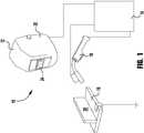
- FIG. 1is a schematic view of a welding system according to the present invention
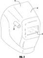
- FIG. 2is an enlarged view of a welding helmet similar to the helmet of FIG. 1 including a camera;
- FIG. 3is a cross-sectional diagram of a welding helmet similar to the helmet of FIG. 2 including a projector;
- FIG. 4is a cross-sectional diagram of a welding helmet similar to the helmet of FIG. 3 including an integrated video display;
- FIG. 5is a perspective view of a welding helmet similar to the helmet of FIG. 2 including binocular cameras;
- FIG. 6is an interior view of a welding helmet similar to the helmet of FIG. 5 showing binocular viewing screens;
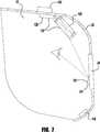
- FIG. 7is a cross-sectional diagram of an exemplary embodiment a welding helmet with a HUD
- FIG. 8is a schematic view of a welding system according to an exemplary embodiment of present invention.
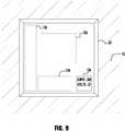
- FIG. 9is an interior view of a welding helmet with a HUD
- FIGS. 10A and 10Bare an interior views of a welding helmet with a HUD
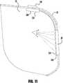
- FIG. 11is a cross-sectional diagram of an exemplary embodiment of a welding helmet with a HUD
- FIG. 12illustrates exemplary views of information that can be displayed.
- FIG. 13illustrates a schematic block diagram of a welding system according to another exemplary embodiment of the invention.
- FIG. 14illustrates a schematic view of the welding system in FIG. 13 .
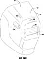
- FIG. 15illustrates a perspective view of a welding helmet with a face-mounted display device.
- FIG. 16Aillustrates an exemplary welding tool showing the placement of point markers used to define the rigid body.
- FIG. 16Billustrates an exemplary welding helmet showing the placement of point markers used to define the rigid body.
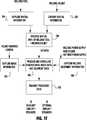
- FIG. 17illustrates a flow chart showing the flow of information in an exemplary embodiment of the invention.
- FIG. 18illustrates a perspective view of the welding environment as viewed on or through the display of a welding helmet.
- FIG. 19illustrates an exemplary user input screen for setting parameters on welding equipment.
- FIG. 20illustrates an exemplary user input screen for selecting a welding procedure.
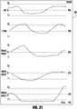
- FIG. 21illustrates an exemplary graph with various plots of welding tool parameters.
- FIG. 22illustrates a perspective view of a welding environment showing real-world objects, visual cues and virtual objects.
- FIG. 23illustrates a top view of a welding environment showing real-world objects and virtual objects.
- FIG. 24illustrates a side view of a welding environment showing real-world objects and virtual objects.
- FIG. 25illustrates a schematic view of another exemplary embodiment of a welding system.
- FIG. 26illustrates a flow chart showing the flow of information in an exemplary embodiment of an object recognition device.
- the welding system 10includes a welding helmet 12 , a welding system 14 , a welding gun 16 and a work piece 18 .
- the work piece 18generally defines a welding work area 20 where the welding gun 16 may be used to form a weld.
- the welding system 14includes welding equipment for generating a welding current and voltage, a welding control system for controlling the welding current and voltage, and a monitoring system for monitoring the welding current and voltage. That is, the welding system, can be on known or used welding power supply having a known construction and operation.
- the monitoring systemmay also monitor a variety of other operating parameters, such as but not limited to, wire feed speed, amount of wire used/amount of wire remaining, any type of welding feedback desired by the operator and any other desired operating parameter.
- the welding helmet 12includes a main body 22 with a visual display 24 connected to the main body 22 .
- the display 24may be a window including a welding lens, a video monitor, such as an LCD display or LED array, or any other device suitable to allow a welder to see the welding work area 20 . It must be understood that in such an example where the display 24 is a video monitor video processing may be utilized to enhance the pictures of the welding operation. Further, recording devices may optionally be included in the display, for example, to record and later playback welding operations for analysis and/or evaluation.
- a welding helmet 12may include a camera 26 mounted at or proximate to the point of view of the welder.
- the camera 26may provide video pictures of the welding work area 20 to the display 24 . Further, the camera 26 can be used to record the welding operation as it is ongoing, so that the welding operation can be viewed at a later time.
- an information generating mechanism 28is in communication with the monitoring system of the welding system 14 and capable of generating an image representative of information from the monitoring system based upon the monitored welding parameter, such as current and voltage upon the visual display 24 where the focus of the image is at a focus range (i.e., having a focal point) with an associated welding work area, e.g. outside of the main body 22 of the welding helmet 12 . That is, the focal range of the image displayed in/on the display 24 is set to be at a range associated with the location of the welding work area 20 .
- the imagemay be symbolic, alpha-numeric, or any other device suitable to indicate the information.
- a weldermay view an image representative of information about a welding operation without removing focus from the work area.
- the weldermay focus on the work area and the image of information at the same time.
- the information based upon welding current and voltageincludes, but is not limited to, welding current feedback, welding voltage feedback, control settings of the welding equipment, statistical information of the welding process, benchmarks or limits including capacity representations, alerts including material shortage or low flow, a representation of an intended or desired weld, etc.
- the camera 26is used to calibrate the depth of the image relative to the welding work area 20 .
- This calibrated depthcan be used to determine the focus of the information displayed on the display 24 .
- the cameras 26determines that the distance from the helmet to the work area is 2 feet, the images and/or information shown on the display 24 is displayed such that the image has a focal point which would be at 2 feet beyond the helmet. As explained above, this allows the displayed information to be displayed at a same focal length as the weld area 20 so that the welder need not change his/her eye focus during a welding operation.
- positions sensors on the welding gunmay be used to calibrate the depth of the image.
- Such sensorscan include, but are not limited to, magnetic sensors, optical sensors, acoustics sensors, and the like, which are sensed using an appropriate sensing system to allow for the positioning of the welding gun to be determined. This data can be used to aid in determining the focal range/distance of the work area relative to the helmet. In particular applications it is highly desirable to carefully align the image and the welding work such that the information represented in the image is easy for the welder to access and such that the information in the image is readily accepted by the welder.
- information generating mechanism 28may include an image representative of information from the monitoring system based upon the monitored parameter, such as welding current and voltage, in video pictures of the welding work area 20 shown on the display 24 .
- the information generating mechanism 28may be in wired or wireless communication with other devices as desired.
- the information generating mechanism 28is a projector.
- the projectormay, for example, include an internal LCD display or LED array 30 along with a number of associated mirrors 32 to reflect the image generated to the visual display 24 .
- the reflected imagegives the image the appearance of depth relative to the visual display 24 and thus puts the image at a focus range with an associated welding work area and outside of the main body 22 of the welding helmet 12 and optionally at the same focal distance as the associated welding work area 20 .
- a reflective surface 34may be placed upon a portion of the visual display 24 in order to achieve a desired amount of reflection or reflection angle.
- teleprompter type technologymay be utilized to place the image upon the display 24 or surface 34 .
- one embodimentincludes the use of an LCD display or other similar display within the helmet to generate the image which is then sent along an optical path, such as by reflection or fiber optics or any other suitable device to place the image display 24 or surface 34 .
- the information generating mechanism 28includes a screen, film, or sheet 36 integrated into the visual display 24 .
- the sheet 36may be a semi-transparent LCD film, electro-optic film, or any other suitable medium for the information generating mechanism 28 to produce an image generated in the visual display 24 .
- the information generating mechanism 28may project a stereogram on the welding lens such that a welder's eyes will separately view the images to create the perception of depth and thus focus the image at a focus range with the associated welding work area 20 and outside of the main body 22 of the welding helmet 12 .
- FIG. 5a welding helmet 12 including binocular cameras 26 a and 26 b .
- these cameras 26 a and 26 bcorrespond to binocular viewing screens 24 a and 24 b .
- An information generating mechanismmay produce an image to be generated in either of the viewing screens 24 a or 24 b or both.
- the cameras 26 a and 26 bare placed in alignment with the screens 24 a and 24 b except on opposite sides of the main body 22 , thus giving the welder the view directly in front of them.
- the perception of depth of fieldis produced.
- the imagemay be an overlay of text or graphics or video feedback.
- the system described abovemay be used in a remote welding situation, including but not limited to robotic welding or underwater welding.
- the HUD 135includes a projector 128 , a combiner 134 , and an information generating device 129 .
- the projector 128can be, e.g., an LED array, an LCD display, a laser, a combination LED/LCD system, or some other suitable projector system.
- the projector 128projects an image onto the combiner 134 .
- the imagecan be in the form of text, graphics, video, etc.
- the projector 128receives image information, e.g., in the form of a digital signal, from information generating device 129 .
- the information generating device 129generates and/or processes the image based on information received from an external source such as, e.g., a welding system 14 or a computer system 160 (see FIG. 8 ).
- This informationcan include, among other types of information, welding parameters such as input power, input current, input voltage, welding voltage, welding current, welding power, tip-to-work distance, arc length, wire feed speed, etc.
- the projector 128 and information generating device 129can be integrated into a single physical unit.
- the computer system 160 and/or the welding system 14generates and/or processes the image and transmits the image information directly to projector 128 , which can include and/or is connected to a wireless communication device.
- the combiner 134reflects the image projected from projector 128 to the welder.
- light transmitted through lens 24is also transmitted through combiner 134 .
- the light transmitted through lens 24can be that from a welding arc transmitted through lens 24 .
- the lens 24is of a type that rapidly and automatically changes from transparent to dark when the lens 24 detects that a welding arc has been initiated. The auto-darkening feature protects the welder's eyes from damage that could occur if the eye is exposed to the welding arc.
- the auto-darkening lensis transparent when no arc is detected and thus allows the welder to see the work space even when the welding helmet 12 is flipped down over the welder's face.
- the light transmitted through lens 24 and combiner 134can be either the light from the welding arc or normal room lighting depending on whether a welding operation is taking place.
- the combiner 134collimates the reflected image such that the projected image appears to be at optical infinity. Thus, the welder will not have to re-focus to see both the work space and the projected image—even during the welding process.
- the combiner 134is an appropriate transparent material, e.g., a flat piece of glass, that is angled such that the projected image from the projector 128 is reflected to the welder as illustrated in FIG. 7 .
- the mounting of the combiner 134 to welding helmet 12 and/or lens 24is such that the angle of reflection can be adjusted by the welder, as desired.
- the combiner 134includes a coating that reflects monochromatic light from the projector 128 .
- the coating on the combiner 134can be such that only, e.g., green light is reflected and all other light is transmitted through.
- the HUD 135will provide the welder a transparent display that allows the welder to see information on the combiner 134 in green while still allowing the welder to view the work space.
- other coatings that reflect other colors or even multiple colorscan be used on the combiner 134 .
- the combiner 134can be coated such that it reflects the colors green and red.
- the informatione.g., welding current
- the informationmay be displayed in green and when outside the normal operating range, the information, e.g., welding current, can be displayed in red.
- the information provided to the weldercan include welding operating parameters such as, e.g., input current, input voltage, input power, welding current, welding voltage, wire feed speed, contact tip-to-work distance, arc length, mode of operation, etc.
- the size, shape, and placement of the combiner 134 relative to the lens 24can vary, as desired.
- FIG. 9illustrates various sizes, shapes, and locations for the combiner 134 .
- the illustrated sizes and locationsare exemplary and any appropriate size, shape, and location can be utilized.
- the combiner 134is sized such that it covers the entire opening of lens 24 (see FIGS. 10A and 10B ). Similarity, an image window, i.e. the window in which actual information is displayed, on the combiner 134 can be sized and/or located as desired. For example, as seen in FIG.
- an image window 136can be displayed in a corner and/or along an edge of the combiner 134 so that the welder is not distracted but still has the information available, if desired.
- the image window 136can be displayed larger as seen in FIG. 10B .
- the HUD 135can be configured such that the image 136 is automatically resized based on whether welding system 14 is performing a welding operation. Alternately, or in addition, the HUD 135 can be configured such that the resizing of image 136 is a manual operation by the welder.
- a HUD 235includes combiner 234 and information generating device 229 .
- the imageis produced directly in the combiner 234 .
- the combiner 234can be, e.g., an LCD display, optical waveguide, an electro-optical medium, or some other suitable medium for producing an image. Similar to combiner 134 discussed above, the size, shape, and placement of the combiner 234 relative to the lens 24 can vary, as desired, including having a display size that is equal to the size of the window of lens 24 . In addition, similar to image window 136 discussed above, an image window on combiner 234 can be sized and/or located as desired.
- the combiner 234receives image information, e.g., in the form a digital signal, from information generating device 229 , which generates and/or processes the image based on information received from welding system 14 and/or computer system 160 .
- the combiner 234 and information generating device 229can be integrated into a single physical unit.
- the combiner 234 and lens 24can be integrated into a single physical unit.
- the combiner 234 , information generating device 229 , and lens 24can be integrated into a single physical unit.
- the computer system 160 and/or the welding system 14generates and/or process the image and transmits the image information directly to combiner 234 , which can include or is connected to a wireless communication device.
- the information generating devices 129 and 229can each include a communication device 150 to communicate via, e.g., a wireless network 170 or a wired network with welding system 14 and/or computer system 160 .
- the wireless network 170can operate using, e.g., Bluetooth, WiFi (IEEE 802.11) or some other wireless protocol.
- the welding system 14can provide information such as e.g., input power, input current, input voltage, welding current, welding voltage, welding power, contact tip-to-work distance, arc length, wire feed speed, etc. in real-time to, e.g., aid the welder while the welding operation is going on.
- the welding system 14can send welding performance information after the welder has stopped welding.
- the welding system 14can transmit information such as, e.g., heat input, duration of welding, etc. after, e.g., the welder system 14 is turned off, indicating that the welder is done welding. Such information might be useful to the welder in order to make corrections before starting the next welding segment.
- the computer system 160performs all the calculations such as, e.g., heat input, welding duration, etc.
- the computer system 160can communicate with the welding system 14 and/or the welding helmet 12 via, e.g., wireless network 170 or a wired network.
- the computer system 160collects, stores, and/or analyzes information received from the welding system 14 .
- the computer system 160transmits the image information to the welding helmet 12 instead of or in addition to the welding system 14 .
- the computer systemis incorporated into or is integral to the welding system 14 .
- the image information seen by the welderis configurable.
- the computer system 160 and/or the welding system 14can be configured with different “views” or image screens that the welder can select.
- the welding informationcan be presented to the welder using several image screens or “views.”
- View 1can represent real-time operating parameters of an engine-driven welder such as, e.g., welder output amps 310 , welder output volts 312 , engine speed 314 , etc.
- a second “view,” View 2can represent performance totals such as, e.g., welding heat input 320 , Auxiliary Power Used 322 , Welding Power Used 324 , etc.
- the HUDcan display engine related information such as RPM, engine temperature, oil pressure, air compressor output pressure (if equipped), and any trouble codes from an engine control computer to allow the welder to be warned of any issues.
- the viewscan be customized to meet the welder's needs.
- the viewscan be customizable based on the type of welding (TIG, MIG, etc.), material being welded (steel, aluminum, etc.), type of weld (fillet, butt joint, etc.), or on some other basis.
- the viewscan be customized for each welder.
- the computer system 160 and/or the welding system 14can display a set of “views” that are specific to the welder, e.g., based on the welder's preferences, experience level, etc.
- the weldercan turn the HUD 135 , 235 on and off and scroll through the “views” using controls (not shown) located on the welding helmet 12 .
- the weldercan control the HUD 135 , 235 using voice commands.
- the welding helmet 12can include a microphone system 140 (see FIG. 7 ) that picks up audio command from the welder.
- the microphone system 140can then relay the audio commands to welding system 14 and/or computer system 160 using communication device 150 .
- the welding system 14 and/or the computer system 160interprets the commands and sends the appropriate instructions and information to the information generating device 129 , 229 .
- Information generating device 129 , 229will then control projector 128 and/or combiner 234 based on the received information and instructions.
- a weldercan say “SHOW CURRENT” and the system will display the welding current.
- Other voice commandscan be used to allow the user to display the desired information. These voice commands can be used, prior to, during or after the completion of a welding process.
- the weldercan adjust the size and location of the image window 136 , the brightness of the image display, the color of the image display, etc.
- the weldercan control the opacity of the image to make the image more or less transparent, e.g., from nearly 100% transparent to 100% opaque.
- some display parameterssuch as, e.g., brightness, opacity, color, etc. can be adjusted automatically by at least one of information generating device 129 , 229 , computer system 160 and welding system 14 based on whether the welding arc is sensed and/or the level of ambient light in the room.
- system 400provides real-time visual feedback while the user performs a weld, which can include, e.g., a real-world weld, a simulated weld, or a combination of real-world weld and a simulated weld. That is, the system 400 can be used in the training of welders in environments where students practice welds on real-world and/or simulated welding coupons and workpieces.
- the simulated objectscan include, but are not limited to, the welding arc, the welding puddle, and/or the welding coupon/workpiece.
- the workpieces, real-world and/or simulatedcan include, e.g., simple objects such as plates, pipes, etc. and complex objects such as parts, devices, and components used in, e.g., machinery.
- some exemplary embodimentscan be used to perform welds in the field, e.g., at a manufacturing site, at a construction site, etc.
- FIGS. 13 and 14provide an overview of a system 400 in accordance with exemplary embodiments of the invention.
- System 400includes a logic processor-based subsystem 410 , which may be programmable and operable to execute coded instructions for generating the visual cues and audio cues to be overlaid and aligned with a digital image of the welding environment 480 and/or displayed on a combiner of a HUD.
- the visual and audio cueswhether by themselves or as part of a composite image stream (e.g., video stream) with the welding environment 480 , are then transmitted to the user (welder) via face-mounted display device 440 A mounted on welding helmet 440 .
- the visual cues and/or a digital image (video) of the welding environment 480are presented to the user.
- the visual cuescan be aligned with preferred areas such as, e.g., corners and along the sides of the display device 440 A and/or the visual cues can be aligned with objects such as the welding tool 460 , welding coupon 480 A or workpiece 480 B, contact tip, nozzle, etc. that are visible on the display device 440 A.
- the display device 440 Acan also playback or display a variety of media content such as videos, documents (e.g., in PDF format or another format), audio, graphics, text, or any other media content that can be displayed or played back on a computer.
- This media contentcan include, for example, instructional information on welding that the trainee can review prior to performing a weld (e.g., general information on welding, information on the specific weld joint or weld procedure the user wishes to perform, etc.).
- the media contentcan also include information on the trainee's performance or the quality of the weld after completion of the weld or training exercise, and/or audio/visual information provided to the trainee during the weld (e.g., if the visual cues are turned off and the trainee's performance is a problem, the system can display and/or provide audio information suggesting that the visual/audio cues be turned on).
- System 400further includes sensors and/or sensor systems, which may be comprised of a spatial tracker 420 , operatively connected to the logic processor-based subsystem 410 .
- the spatial tracker 420tracks the position of the welding tool 460 and the welding helmet 440 relative to the welding environment 480 .
- the system 400can also include a welding user interface 430 in communication with the logic processor-based subsystem 410 for set up and control of the system 400 .
- the system 400also includes an observer/set-up display device 430 A connected to, e.g., the welding user interface 430 .
- Each display device 440 A, 430 Acan provide a view of the welding environment 480 that has been overlaid with visual cues.
- the system 400also includes an interface that provides communication between programmable processor-based subsystem 410 and a welding power supply 450 in order to receive welding parameters such as, e.g., voltage, current, power, etc.
- the system 400includes a video capture device 470 that includes one or more cameras, e.g., digital video cameras, to capture the welding environment 480 .
- the video-capture device 470can be mounted on the welding helmet 440 , similar to helmet 12 discussed above with reference to FIGS. 2 and 5 .
- the signal from the video capture device 470provides the field of view that the user sees while welding.
- the signal from the video-capture device 470can be sent to the programmable processor-based subsystem 410 for processing of the visual cues.
- either the visual cues or both the visual cues and video of the welding environment 480are sent to the face-mounted display 440 A.
- the video cuesare mapped and transmitted to the combiner so as to match the field of view of the user through the face-mounted display 440 A.
- the spatial tracker 420measures the motion of welding tool 460 and/or welding helmet 440 and gathers process data during the welding exercises.
- the spatial tracker 420uses one or more of the following tracking systems: a single or multiple camera based tracking system (e.g., based on point cloud image analysis), a magnetic-field based tracker, an accelerometer/gyroscope based tracker, an optical tracker, an infrared tracker, an acoustic tracker, a laser tracker, a radio frequency tracker, an inertial tracker, an active or passive optical tracker, and a mixed reality and simulation based tracking. Still, other types of trackers may be used without departing from the intended scope of coverage of the general inventive concepts.
- GMAWGMAW
- FCAWFCAW
- SMAWSMAW
- GTAWGTAW
- claddingcladding
- cuttingjoining, cladding, etc.
- the logic processor-based subsystem 410includes at least one computer for receiving and analyzing information captured by the spatial tracker 420 , image capture device 470 and welding process data transmitted by the welding power supply 450 .
- the computeris typically running software that includes a welding regimen module, an image processing and rigid body analysis module, and a data processing module.
- the welding regimen moduleincludes a variety of weld types and a series of acceptable welding process parameters associated with creating each weld type. Any number of known or AWS weld joint types and the acceptable parameters associated with these weld joint types may be included in the welding regimen module, which can be accessible and configurable by user, a welding instructor, etc. to add modify or delete any information in the welding regimen module.
- the logic processor-based subsystem 410can import weld joints and/or specific welds corresponding to custom parts, devices, components, etc. into the welding regimen module.
- the logic processor-based subsystem 410can import design model information, e.g., CAD format (2-D or 3-D) (or another type of design format), of any complex custom part, device, component, etc. that is welded as part of the fabrication process (e.g., parts, devices, components, etc. used in any industrial, manufacturing, agricultural, or construction application or any other application).
- design model informatione.g., CAD format (2-D or 3-D) (or another type of design format
- the number and types of joints used in manufacturing the custom part, device, component, etc.can be identified and stored in the welding regimen module as a custom weld type.
- the acceptable parameter limits associated with these weld joint typescan be input by, e.g., the instructor or, preferably, included in the design file (e.g., CAD file) from the manufacturer, and are then read by the logic processor-based subsystem 410 .
- the logic processor-based subsystem 410can import a design of an automobile axle, e.g., in 2-D or 3-D CAD format.
- the number and type of joints used in manufacturing the axlecan be identified (either by, e.g., the instructor, or automatically read in as part of the file, e.g., 2-D or 3-D CAD format) and stored in the welding regimen module as a custom weld type or types.
- the acceptable parameters associated with the custom weld typesare also stored in the welding regimen module.
- information for the custom part, device, component, etc.is also used by embodiments of the logic processor-based subsystem 410 for workpiece recognition and auto-calibration of the system as discussed below.
- the weld process and/or type selected by the user prior to weldingdetermine which acceptable welding process parameters are used for any given welding exercise.
- the object recognition moduleis operative to train the system to recognize known rigid body objects, which can include two or more point markers, and then calculate position and orientation data for, e.g., welding tool 460 and welding helmet 440 as a manual weld is completed by the user.
- the object recognition modulecan also be uploaded or configured with information for recognizing custom parts, devices, components, etc. discussed above.
- the data processing modulecompares the information in the welding regimen module to the information processed by the object recognition module and outputs feedback to the user.
- the logic processor-based subsystem 410can provide any type of feedback to the user (typically in real time) via various means including, but not limited to, one or more of in-helmet visual feedback, visual feedback on a separate monitor, audio feedback (e.g., tones, coaching, alarms) via speakers, and additional visual, audio, or tactile feedback using the welding tool (e.g., torch, welding gun).
- the real-time visual feedbackcan be provided to the user and/or an observer as the user welds on a welding coupon 480 A or a workpiece 480 B, each of which can have a range of configurations, including large sizes, various joint types, pipe, plate, and complex shapes and assemblies.
- measured parameterswhich are provided as the feedback, include, but are not limited to, aim, work angle, travel angle, tool standoff, travel speed, bead placement, weave, voltage, current, wire feed speed, arc length, heat input, gas flow (metered), contact tip to work distance (CTWD), and deposition rate (e.g., lbs./hr., in./run).
- the face-mounted display 440 A and/or welding user interface 430 with display device 430 Aallows the user and/or an observer to visualize the processed data in real time and the visualized data is operative to provide the user with useful feedback regarding the characteristics and quality of the weld.
- the feedback datais automatically recorded and saved in a data storage device, e.g., hard disk drive, or other known storage means by logic processor-based subsystem 410 .
- the logic processor-based subsystem 410can include memory, e.g., RAM, ROM, EPROM, hard disk drive, CD ROM, removable drives, flash memory, etc., that can be pre-populated with specific welding procedures, which can include procedures that have been customized, e.g., by an experienced welder, a manufacturer, etc.
- the procedurescan include information related to the visual and audio cues such as the criteria for changing the attributes of the visual and audio cues.
- the procedurescan include information on the target values and target ranges for parameters such as aim, work angle, travel angle, tool standoff, travel speed, bead placement, weave, voltage, current, wire feed speed, arc length, heat input, gas flow (metered), contact tip to work distance (CTWD), deposition rate (e.g., lbs./hr., in./run), etc. based on the type of welding process, the type of the welding gun, the type and orientation of the weld joint, the type of material being welded, the type of the electrode, the type and size the filler wire (if any), etc.
- the logic processor-based subsystem 410can perform real-time and a post-weld analysis that scores the performance of the welder, user.
- the logic processor-based subsystem 410can provide other information such as the potential existence of faults in the weld (e.g., porosity, incomplete fusion (not enough penetration), crack in the weld, undercut, weld profile is too thin, weld profile is too thick, etc.) and how to avoid the faults in real-time and/or in a post-weld analysis.
- the progress of the useris tracked over time, which can be a beneficial aid to a trainer in identifying areas where the user may need additional teaching.
- exemplary embodiments of the inventionare not limited to a traditional training environments where welders, whether beginners, intermediate or experienced, practice welding on welding coupons such as, e.g., welding coupon 480 A.
- Exemplary embodiments of the inventioncan be used in actual working environments and the visual and audio cues, which are discussed further below, aid the welder in performing the weld. For example, a beginner can use the visual and audio cues to make sure the welding gun is oriented properly and the travel speed is correct. Experienced welders can also benefit from the visual and audio cues when, e.g., welding on a workpiece and/or using a filler wire whose material is new to the welder, working at an orientation that is unfamiliar, when using a non-traditional welding procedure, etc.
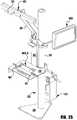
- FIG. 14provides an illustrative view of a welding application incorporating system 400 in accordance with an exemplary embodiment the present invention.
- stand 520includes a substantially flat base 522 for contact with a floor or other horizontal substrate, rigid vertical support column 524 , tracking system (e.g., camera or imaging device) support 526 , and rack and pinion assembly 531 for adjusting the height of the tracking system support 526 .
- tracking systeme.g., camera or imaging device
- rack and pinion assembly 531for adjusting the height of the tracking system support 526 .
- a motor operated assemblycan be used for adjusting the height.
- the portable stand 520can be used in a training environment where the user performs welding operations (real-world and/or simulated) on welding coupon 480 A and/or in a manufacturing environment in which welding is performed on workpiece 480 B which can be small to medium sized objects.
- welding operationsreal-world and/or simulated
- workpiece 480 Bwhich can be small to medium sized objects.
- the system 400can also be used on larger workpieces and in construction sites.
- the stand 520 and attached equipmentcan be portable or at least moveable from one location to another, therefore the overall footprint of base 522 is relatively small to permit maximum flexibility with regard to installation and use.
- the stand 520 and attached equipmentcan be fixed at a particular location, e.g., a welding booth, which can have other equipment such as an exhaust hood,
- the stand 520 and attached equipmentallow for any suitable arrangement of workpieces including, but not limited to, flat, horizontally, vertically, overhead, and out-of-position oriented workpieces.
- stand 520is depicted as a unitary or integrated structure that is capable of supporting some of the components of the system 400 .
- stand 520is absent and the various components of the system 400 are supported by whatever suitable structural or supportive means may be available.
- “stand” 520is defined as any single structure or, alternately, multiple structures that are capable of supporting one or more of the components of welding system 400 .
- the face mounted display device 440 Amay be integrated into a welding helmet 440 .
- the system 400can include a display device that the user wears as glasses.
- the face mounted display device 440 Acan include two high-contrast SVGA 3D OLED micro-displays capable of delivering fluid full-motion video in the 2D and frame sequential video modes.
- images (e.g., video) of the welding environment 480are provided and displayed on the face mounted display device 440 A via video capture device 470 having cameras 470 A, 470 B mounted on welding helmet 440 , e.g., mounted as shown in FIGS.
- the logic processor-based subsystem 410provides stereoscopic video to the face mounted display device 440 A, enhancing the depth perception of the user.
- a zoom (e.g., 2 ⁇ , 3 ⁇ , etc.) modemay also be provided as an aid to the user.
- the face-mounted display device 440 Ais a see-through type display and is constructed similar to HUD 235 of FIG. 11 with a combiner and lens, e.g., an auto-darkening lens, as discussed above.
- the helmet 440operatively connects to the logic processor-based subsystem 410 and the spatial tracker 420 via wired or wireless means, e.g., in FIG. 14 , wireless network 475 is used.
- sensorseither passive or active
- sensorscan be attached to the welding helmet 440 thereby allowing the face mounted display device 440 A to be tracked with respect to the 3D spatial frame of reference created by the spatial tracker 420 .
- movement of the welding helmet 440responsively alters the visual cues seen by the end user such that the visual cues are aligned with the objects, e.g., welding tool 460 , welding coupon 480 A, workpiece 480 B, etc., in the field of view of the user.
- the face-mounted display 440 Acan display menu items for configuration and operation of system 400 .
- selection of the menu itemscan occur based on controls mounted on the welding tool 460 (e.g., buttons, switches, knobs, etc.).
- the menu itemscan be displayed on display device 430 A of welding user interface 430 and the selections can be made using traditional input devices such as, e.g., a mouse and keyboard.
- the selection of the menu itemscan be accomplished voice activated commands.
- the menu screencan be displayed by saying, e.g., “MENU” and navigating the menu screen can be accomplished by saying, e.g., “UP, DOWN, LEFT, RIGHT” and selection can be accomplished by saying, e.g., “SELECT.”
- the selection of the menu itemscan be done by tracking the eyes of the user. As the user's eyes focus on a menu item, the menu item is highlighted. Preferably, selection of the highlighted menu item is accomplished by blinking the eyes, e.g., a single-blink, double blink, etc.
- any combination of welding tool controls, audio input and eye tracking inputcan be used to navigate through the menu items.
- the eyescan be used to highlight the menu item and voice commands and/or the welding tool controls are used to select the highlighted item.
- the welding helmet 440may further include speakers 440 B, allowing the user to hear audio cues. Different sounds can be provided depending on if certain welding or performance parameters are within tolerance or out of tolerance. For example, a predetermined tone can be provided if the travel speed is too high and a different predetermined tone can be provided if the travel speed is too low. Sound may be provided to the user via speakers 440 B, which may be earbud speakers or any other type of speakers or sound generating device, mounted in the welding helmet 440 and/or mounted separately, e.g., on the welding table. Still, any manner of presenting sound to the end user while engaging in welding activity may be chosen. It is also noted here that other types of sound information may be communicated through the speakers 440 B.
- Examplesinclude verbal instructions from an instructor or an expert, in either real time or via prerecorded messages. Prerecorded messages may be automatically triggered by particular welding activity. Real time instructions may be generated on site or from a remote location. Still, any type of message or instruction may be conveyed to end user.
- determining the orientation of the welding tool 460 and the welding helmet 440includes capturing images of the respective objects with one or more off-the-shelf high-speed-vision cameras, which can be mounted on tracking system support 526 of stand 520 or another fixed location relative to the welding environment 480 .
- the processing of the captured imagesincludes creating an image file at many (e.g., over 100) frames per second.
- the one or more camerastypically capture at least two point markers located in a fixed geometric relationship to one another on each of the respective objects, welding tool 460 and welding helmet 440 , 22 .
- welding coupon 480 A and workpiece 480 Bcan include point markers so that their position and orientation can also be determined based on the images captured by the cameras.
- processing of the captured imagesis performed in the spatial tracker 420 and/or the logic processor-based subsystem 410 .
- tracking of the objects in 3-D space, including the welding environment 480can be accomplished by using point markers on the objects, e.g., welding tool 460 , welding helmet 440 , welding coupon 480 A, workpiece 480 B, etc.
- point markerse.g., welding tool 460 , welding helmet 440 , welding coupon 480 A, workpiece 480 B, etc.
- target 600is mounted on welding tool 460 .
- a rigid body point cloudi.e., a “rigid body” is constructed by attaching active or passive point markers 602 , 604 , and 606 (and possibly additional point markers) to the upper surface of target 600 .
- Passive point markerscan be, e.g., reflective markers such as e.g., reflective tape or stickers that are adhesively attached to target 600 or attached by other known means.
- Active markerscan include LEDs (e.g., infrared LEDs), or other sensors that are, e.g., fastened to the target 600 .
- Target 600can include a power input if the point markers used are active and require a power source.
- the point markerscan be attached or mounted directed on the “rigid body,” e.g., welding tool 460 or welding helmet 440 , if desired, rather than using a separate target. For example, as shown in FIG. 16B , point markers 652 , 654 , 656 , 658 and 660 are placed on the welding helmet 440 .
- the passive or active point markersare affixed to the target 600 and/or directly to welding tool 460 and welding helmet 440 in a multi-faceted manner so that a wide range of rotation and orientation changes can be accommodated within the field of view of the imaging system.
- the point markers corresponding to the welding tool 460 and welding helmet 440are respectively correlated or calibrated so as to form “rigid bodies,” i.e., the body 620 , trigger 622 , nozzle 624 and tip 626 of the welding tool 460 have a known spatial relationship to each other and the display 440 A and the body of welding helmet 440 have a known spatial relationship to each other.
- additional calibration stepsmay be needed to calibrate the “rigid body” to other points.
- the “rigid body” formed by points 602 , 604 , and 606can then correlated or calibrated to point 628 using a known distance between point 628 and 626 . Calibration of welding tools and welding helmets to tracking systems is known in the art and thus, for brevity will not be further discussed.
- spatial tracker 420uses a tracking system such as e.g., Optitrack Tracking Tools or similar hardware/software to locate and track the rigid bodies.
- the image processingthen includes frame-by-frame point cloud analysis of the rigid bodies (i.e., the calibrated targets, which can include welding tool 460 and welding helmet 440 ) that includes three or more point markers.
- the rigid bodiesi.e., the calibrated targets, which can include welding tool 460 and welding helmet 440
- position and orientationare calculated relative to the camera origin and the “trained” rigid body orientation.
- Calibrating and “training” the spatial tracker 420 to recognize the position and orientation in three-dimensional space of rigid bodies such as the welding tool 460 and welding helmet 440is known in the relevant art and thus, for brevity, will not be discussed in detail.
- the spatial tracker 420can include any suitable data capturing system such as, for example, the Optitrack Tracking Tools (provided by NaturalPoint, Inc.
- more than one camerais used to track welding tool 460 and welding helmet 440 .
- Capturing and comparing the images from two or more camerasallows for a substantially accurate determination of the position and orientation in three-dimensional space of welding tool 460 and welding helmet 440 .
- Imagesare typically processed at a rate of more than 100 times per second.
- a lesser sampling ratee.g., 10 images/sec.
- a greater sampling ratee.g., 1,000 images/sec.
- the output aspect of image processingincludes creation of a data array that includes x-axis, y-axis, and z-axis positional data and roll, pitch, and yaw orientation data, as well as time stamps and software flags.
- Text filesmay be streamed or sent by the spatial tracker 420 at a desired frequency to the programmable processor-based subsystem 410 or, in some embodiments, be generated by the logic processor-based subsystem 410 .
- spatial tracker 420is described as a single or multiple camera based tracking system based on point cloud image analysis, those skilled in the art understand that other type of tracking systems can be used, e.g., a magnetic-field based tracker, an accelerometer/gyroscope based tracker, an optical tracker, an infrared tracker, an acoustic tracker, a laser tracker, a radio frequency tracker, an inertial tracker, an active or passive optical tracker, and mixed reality and simulation based tracking.
- a magnetic-field based trackere.g., an accelerometer/gyroscope based tracker, an optical tracker, an infrared tracker, an acoustic tracker, a laser tracker, a radio frequency tracker, an inertial tracker, an active or passive optical tracker, and mixed reality and simulation based tracking.
- the cameras 470 A, Bare discussed above as providing a “field of view” of the user to the system 400 , the cameras 470 A, B can also be configured to track objects in the welding environment 480 , instead of the cameras on tracking system 526 .
- an appropriate alternate fixed reference point in the welding environment 480must be used because the cameras 470 A, B will move with the movement of the user.
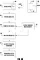
- FIG. 17illustrates the basic flow of information in the system 400 .
- the system 400captures spatial information regarding the position, orientation and motion of the welding tool 460 .
- the system 400also captures the position, orientation and motion of the welding helmet 440 with face-mounted display device 440 A.
- the spatial tracking information of the welding tool 460 and the welding helmet 440is processed to determine the position and orientation of the welding tool 460 and welding helmet 440 in three-dimensional space relative to the welding environment 480 and preferably includes creating 6-D data files for the welding tool 460 and welding helmet 440 .
- the digital image data (e.g., video) from one or more cameras mounted, e.g., on the welding helmetis captured for processing in, e.g., data processing block 540 .
- welding process parameterssuch as those transmitted by welding equipment, e.g., welding power supplies (e.g., current, voltage, etc.), wire feeders (wire feed speed, etc.), hot-wire power supplies (current, voltage, temperature, etc.), or some other piece of welding equipment are captured for processing in block 540 .
- the welding process parameterscan also include heat input (which can be calculated, e.g., using welding current, welding voltage and travel speed), arc length (which can be determined based on welding voltage) and other calculated welding parameters.
- the data processing in block 540includes correlating the view of the welding environment 480 from the helmet-mounted cameras to the tracking data processed in block 530 , i.e., the 6-D data of the tracked welding tool and the tracked welding helmet.
- the position and orientation information of objectssuch as the welding tool 460 , welding coupon 480 A and workpiece 480 B are mapped to the image data captured by image capture device 470 .
- the welding process parameters from block 560are processed with the mapped image and tracking data to create an image stream showing the welding environment with visual cues.
- audio cues based on the welding process parameters and the tracked dataare also generated in block 540 to create an audio stream that can be transmitted to the welding helmet 440 along with the image stream.
- the image stream and audio streamare combined to create a composite audiovisual stream that is sent to welding helmet 440 .
- the data processing step in block 540includes algorithms to generate target values and target ranges for welding parameters such as, e.g., aim, work angle, travel angle, tool standoff, travel speed, bead placement, weave, voltage, current, wire-feed speed, arc length, heat input, gas flow (metered), contact tip to work distance (CTWD), deposition rate, frequency of TIG filler addition, using algorithms specific to a selected welding process, joint type, material being welded, joint orientation, etc.
- the data processing step in block 540also includes algorithms to generate visual and audio cues based on the welding process parameters and tracked data and algorithms to properly place the visual and audio cues on the in-helmet display as discussed below.
- the digital image data and audio data processed in block 540is transmitted to external devices.
- the image datacan be viewed on, e.g., a monitor, in-helmet display, heads-up display, or combinations thereof and audio data (e.g., audio coaching, alarms, tones, etc.) may be directed to external speakers, in-helmet speakers, ear buds, etc.
- audio datae.g., audio coaching, alarms, tones, etc.
- the digital image data and audio datacan be transmitted to the face-mounted display 440 A and speakers 440 B of welding helmet 440 and optionally to display device 430 A of welding user interface 430 .
- the digital image data and audio datainclude visual and audio cues, respectively, relate to welding data.
- the visual and audio cuesrelate to, but are not limited to, aim, work angle, travel angle, tool standoff, travel speed, bead placement, weave, voltage, current, wire-feed speed, arc length, heat input, gas flow (metered), contact tip to work distance (CTWD), deposition rate, frequency of TIG filler addition.
- the logic processor-based subsystem 410can also generate tactile feedback that is sent to the welding tool 460 if so configured. For example, a vibrator on the welding tool 460 can be triggered if the welding process goes into an alarm condition.
- the welding tool 460can provide visual feedback using e.g., LCDs, LEDs, etc.
- the feedbackwhether visual, audio or tactile, is presented to the user in real time as the user is performing a weld on, e.g., the real and/or simulated welding coupon 480 A or workpiece 480 B.
- the visual and audio cuescan be provided to the user to aid the user in the welding process.
- the visual cuescan appear as alphanumeric characters, symbols, graphics, icons, colors, etc.
- the audio cuescan be in the form of tones, alarms, buzzers, audio instructions (either live or pre-recorded and either a human voice or a computer-generated voice).
- the visual cuescan be displayed in any desired location on the display of the face-mounted display device 440 A.
- FIG. 18illustrates an image of the welding environment 480 on display 441 as seen by the user when viewing through the face-mounted display device 440 A.
- the display 441is a monitor that can show a video of the welding environment 480 or is a HUD with an auto-darkening welding lens with combiner.
- the visual cuescan be directly mapped to any desired location on the display 441 , e.g., see 720 where arc length and heat input are directly mapped on display 441 .
- the visual cuesare provided in one or more image windows 702 that can be placed in the corners, along the top, bottom or side of the display 441 or any other desired location on the display 441 .
- related visual cluescan be grouped together in a window 702 .
- current, voltage and wire feed speedcan be grouped in a window 702 .
- the image windows 702can be moved as desired, e.g., by using appropriate controls on the welding tool 460 , voice command, etc.
- the information provided by the visual cuescan relate to, but are not limited to, parameters such as, e.g., aim, work angle, travel angle, tool standoff, travel speed, bead placement, weave, voltage, current, wire feed speed, arc length, heat input, gas flow (metered), contact tip to work distance (CTWD), TIG filler input frequency, etc.
- the visual cues 700can be overlaid on or adjacent to an object in the welding environment 480 as viewed on display 441 .
- the visual cues 700can be linked to the welding tool 460 in the image stream sent to display device 440 A so as to be “attached” to the welding tool, i.e., the visual cues 700 move with the welding tool 460 .
- the visual cues 700can be attached to any object in the welding environment 480 , even if the object is not designed to move, such as e.g., the welding coupon 480 A or workpiece 480 B.
- the visual cues 700are semi-transparent in that the user will be able to see objects in the welding environment that are covered by the visual cue.
- the visual cues 700can be “attached” to a location on the screen where the relevant object, e.g., welding tool 460 , weld coupon 480 A, workpiece 480 B, weld joint, etc., is calculated to be in the “field of view” of user based on the tracking information from the spatial tracker 420 .
- the logic processor-based subsystem 410can calculate the X and Y coordinates on the video image or display 441 where an object such as, e.g., welding tool 460 , will be located, and the subsystem 410 can then map the visual cues 700 to appropriate X and Y coordinates on the video image or display 441 corresponding to the object. For example, as seen in FIG. 18 , visual cues 700 for CTWD 704 , work angle 706 and travel speed 708 are overlaid on the welding tool 460 .
- the visual cues CTWD 704 , work angle 706 and travel speed 708will move with the welding tool 460 so as to maintain the same relative position to the welding tool 460 .
- other visual cuescan be fixed to a location on the display 441 .
- visual cuessuch as welding voltage 712 , welding current 714 and wire feed speed 716 are fixedly mapped to a corner of display 441 in a window 702 and visual cues 720 are fixedly mapped to a position on the display 441 .
- the visual cuescan also be fixed to a location corresponding to a fixed object such as welding coupon 480 A or workpiece 480 B.
- the visual cues 700can be mapped to any desired location on the display 441 .
- the logic processor-based subsystem 410maps the visual cues 700 such that certain aspects of the welding operation such as, e.g., the arc and weld joint, are not obstructed by the visual cues 700 .
- the system 400can use point markers as discussed above (or some other type of tracking system).
- the spatial tracker 420 and/or the logic processor-based subsystem 410can then automatically identify the objects in the welding environment 480 based on analyzing the digital image from the tracking cameras.
- the visual cues 700automatically move locations on the display 441 if the programmable processor-based subsystem 410 determines that movement of the welding torch or some other obstruction will interfere with the user's ability to view the welding operation and/or visual cue.
- the tracked parameterssuch as the position, orientation and movement of welding tool 460 and welding process parameters such as welding voltage, welding current, wire feed speed, etc. can be compared to upper and lower target thresholds, target values or preferred variations for the type of welding process (e.g., GMAW, FCAW, SMAW, GTAW), the type and orientation of the weld joint, the type materials, etc.
- the upper and lower thresholds or preferred variationscan be based on the motions of an expert welder, based computer modeling, testing of similar prior welds, etc.
- the welderwhen a welder performs a weld (e.g., expert welder, instructor, a trainee, etc.), the position, orientation and movement of welding tool 460 of the welder and welding process parameters such as welding voltage, welding current, wire feed speed, etc. are recorded. After completing the weld, the welder can select an appropriate menu item that “clones” the procedure. The “cloned” procedure is then stored and can serve as a reference for future welding procedures.
- the upper and lower target thresholds, target values or preferred variationscan be entered manually by the welder and, more preferably, are automatically entered using default values, e.g., ⁇ 5% or some other appropriate value.
- the upper and lower target thresholds, target values or preferred variationsare configurable by the user.
- the programmable processor-based subsystem 410changes an attribute, e.g., color, shape, size, intensity or brightness, position and/or some other characteristic, of the appropriate visual cue.
- the programmable processor-based subsystem 410can change the color of the visual cue from green to yellow to red depending on the amount of deviation, and/or the visual cues can graphically show the amount of deviation from the target.
- the travel speed 708shows the target value T and the amount of deviation from the target value 730 using a pointer 732 against a meter-type graphic.
- one or more of the visual cues 700can be programmed to change one or more attributes such as, e.g., color, shape, size, intensity or brightness, position and/or some other characteristic of the visual cue 700 when the tracking parameter and/or welding process parameter associated with the visual cue deviates from a target, e.g. falls outside of upper and lower target thresholds, target values or preferred variations for the type of welding process.
- attributessuch as, e.g., color, shape, size, intensity or brightness, position and/or some other characteristic of the visual cue 700 when the tracking parameter and/or welding process parameter associated with the visual cue deviates from a target, e.g. falls outside of upper and lower target thresholds, target values or preferred variations for the type of welding process.
- the amount of deviationis taken into account when determining a change in one or more attributes of the visual cue.
- a visual cue 700can have a green color if the visual cue 700 is within upper and lower target thresholds, at the target value (within an acceptable tolerance) or within preferred variations for the type of welding process.
- the visual cue 700can be programmed to change its color (e.g., to yellow), shape, size, intensity or brightness, position and/or some other characteristic to provide a warning to the user if the associated parameter falls outside the upper and lower target thresholds, target value (e.g., outside an acceptable tolerance) or outside of preferred variations for the type of welding process by a first predetermined amount or warning level, e.g., a deviation that will produce an acceptable weld but not the best weld.
- the system 400provides one or more warning levels or one or more of the visual cues 700 .
- the visual cue 700can also be programmed to further change its color (e.g., to red), shape, size, brightness, position or some other characteristic to provide an alarm to the user if the associated parameter falls outside the upper and lower target thresholds, target value (e.g., outside an acceptable tolerance) or outside of preferred variations for the type of welding process by a second predetermined amount or alarm level, which is greater than the first predetermined amount.
- the second predetermined amount or alarm levelcan be a deviation that will likely produce an unacceptable weld.
- the system 400provides one or more alarm levels for one or more of the visual cues 700 .
- any combination of the attributes of the visual cue 700can be changed.
- any combination of the color, the size, brightness and/or any other attribute of the visual cue 700can be changed.
- any number and combination of warning and alarm levelscan be programmed into the logic processor-based subsystem 410 .
- Visual cues 700are not limited to just providing warnings and alarms.
- visual cues 700can aid in identifying to the user the weld start position, the weld stop position and the total length of the weld.
- the visual cues 700can aid the user in identifying the start position by having a marker such as, e.g., a green spot at the start position and a second marker such as, e.g., a red spot at the stop position.
- the visual cuesaid in achieving the proper weld length. For example, an indication, e.g.
- a green spotis turned on at the start position (or any other desired location on display 441 ) to start the weld and the user welds until the indication is turned off or changes color to achieve the desired weld length.
- the visual cues 700aid in the welding sequence to be followed. For example, if the welding should be done from the center of the workpiece and outward to the ends in order to reduce stresses in the workpiece, the visual cues 700 can alert the user, e.g., by displaying a message in text, e.g., in a corner of the display 441 , or by using visual cues 700 to identify the start position, stop position and weld length as discussed above.
- the visual cues 700provide an indication of the welding progression.
- a visual cuecan provide the percent completion of a weld joint in, e.g., a corner of the display 441 or some other desired location, and/or provide an indication of the pass number in a multi-pass weld.
- the visual cues 700also aid the user in performing the weld.
- a visual cuecan provide an indication, e.g. a bright spot that cycles in the preferred weave pattern at the end of the welding tool tip for the user to copy while welding.
- the visual cuescan indicate the proper frequency at which the filler wire should be added to the weld puddle.
- a pulsating markere.g., a green spot that changes brightness
- the userknows to add the filler wire at the frequency of the pulsations, e.g., dip the filler wire in the weld puddle whenever the marker is ON or brighter (or when the marker is OFF or dimmer).
- Audio cuescan also be used to aid the user. For example, similar to visual cues, audio warning and alarms can be sent to speakers in the welding helmet 440 to alert the user if the position, orientation or movement of the welding tool 460 and/or the welding process parameters fall outside the upper and lower target thresholds, target value (e.g., outside an acceptable tolerance) or outside of preferred variations for the type of welding process.
- the warningscan be in any audio format, e.g., tones of different frequencies, buzzers, and voice alerts. Different frequencies and/or pitches can indicate to the user which parameter is not on target and the amount of deviation.
- the logic processor-based subsystem 410provides voice alerts to inform the user of problems.
- the voice alertcan instruct the user that the travel speed is too fast or too slow.
- Voice alertscan provide instructions or suggestions to the user in making any necessary corrections. Similar to the visual cues discussed above, voice alerts can also aid the user in making the weld, e.g., weave pattern, TIG welding, start and stop indicators, weld length, sequencing, and/or welding progression.
- Audio cuescan be provided in place of the visual cues discussed above. Preferably, a combination of audio cues and visual cues are provided by logic processor-based subsystem 410 .
- the visual and audio cuescan be selectively turned ON or OFF by the user.
- the usercan select whether to fixedly locate the visual cues 700 in a desired location on display 441 such as, e.g., a corner or along one of the sides of display 441 , or “attach” the visual cues 700 to an object on the display 441 such as, e.g., welding tool 460 .
- the user 441can individually select the visual cue 700 or audio cue to turn ON or OFF.
- the visual cues 700 and/or the audio cuesare grouped so that the user can select a group of cues to turn ON or OFF.
- cues related to information from the welding power supply 450can be grouped together and information related to welding tool 460 can be grouped together.
- the groupingcan be preprogrammed or custom programmed, e.g., by the user.
- the usercan use the display 441 and user controls on, e.g., welding tool 460 or a remote control device, to activate or deactivate the visual and audio cues.
- the usercan use welding user interface 430 for activating and deactivating the cues.
- the usercan activate and deactivate the cues using voice commands. For example, the user can say “GROUP 1 ON” to activate the visual cues and/or audio cues related to the welding tool 460 .
- the usercan say “GROUP 1 ATTACH”.
- eye trackingas discussed above, can be used to highlight and select an appropriate menu item(s) to activate and deactivate the cues.
- welding data related to the position, orientation and movement of welding tool 460 and/or welding process parametersis stored as the user performs the weld.
- the stored datacan be retrieved for subsequent review for training or certification purposes.
- the programmable processor-based subsystem 410can store the welding data (e.g., as a *.dat file), for reviewing the progress and/or performance of the welder at a later time.
- the stored weld datacan be used as the target values for the visual and audio cues.
- the stored target weld datacan be that of a successful weld by an expert welder or even a successful prior welding run by the user.
- the stored target weld datais based on computer modeling for the specific type of weld and/or testing of similar prior welds.
- the stored target weld dataincludes information related to the weld weave pattern, TIG welding information such as filler frequency, welding start and stop indicators, weld length, welding sequencing, and welding progression.
- TIG welding informationsuch as filler frequency, welding start and stop indicators, weld length, welding sequencing, and welding progression.
- welding system training softwareto train welders, whether beginners or experienced, can be loaded into and executed by the logic processor-based subsystem 410 .
- the userselects the appropriate welding training procedure and starts to perform the welding.
- the training softwaremonitors and records the performance of the user as the user performs a weld.
- welding equipmentsuch as the power supply, wire feeder, hot-wire power supply, etc. do not communicate with the welding training computer. This means that, before or after the user selects a welding training procedure to run, the user must set up the power supply and possibly other welding equipment such as the wire feeder and/or a hot-wire power supply based on the selected welding training session.
- the welding equipmente.g., the power supply
- the welding equipmentis located remotely from the welding training area. This means that any changes to the settings or verification of the settings on the welding equipment, e.g., the power supply, will require the user to exit the training area, and the trips to the welding equipment can occur multiple times during a welding training session, which can become cumbersome.
- the tracking and monitoring of the welding tool 460 and/or the welding helmet 440 as the user performs the weldingare discussed above with respect to system 400 , for brevity, the tracking and monitoring will not be repeated.
- the following exemplary embodimentswill be described in terms of the welding training system communicating with a power supply. However, those skilled in the art will understand that the welding training system can also communicate with other welding equipment such as wire feeders, hot-wire power supplies, etc.
- usercan communicate with welding equipment such as the power supply 450 using either the face-mounted display device 440 A or the observer/set-up display device 430 A connected to the welding user interface 430 .
- welding equipmentsuch as the power supply 450
- the usercan also setup, view and change settings on the power supply 450 .
- the useruses display 430 A and input device 430 B (e.g., keyboard, mouse, or any other known inputting device) of the welding user interface 430 to communicate with the power supply 450 via the logic processor-based subsystem 410 .
- the usercan select a setup screen for setting parameters of the welding equipment.
- FIG. 19illustrates an exemplary embodiment of a setup screen 800 for setting, viewing and/or changing power supply settings.
- the screen 800includes power supply settings that can be changed manually via input fields.
- the usercan set the welding mode of the power supply 450 .
- the usercan select, e.g., by using a dropdown box 802 or some other input means, a mode of operation for the power supply 450 such as, e.g., GMAW, FCAW, SMAW, GTAW.
- a mode of operation for the power supply 450such as, e.g., GMAW, FCAW, SMAW, GTAW.
- one or more additional parameters 804can be made available to the user for review and to change, if needed. For example, as seen in FIG.
- settingssuch as waveform type (short-arc welding, pulse welding, etc.), output voltage and output current have been shown for viewing and/or modification. Of course other parameters such as polarity (positive or negative), inert gas flow setting, etc. can also be made available to the user. Similar to the welding mode setting, the selection of values for each of the parameters 804 can be made via dropdown boxes 802 or some other input means. Preferably, the parameter settings can have an initial default value in order to minimize the setup time for the user.
- the power supply 450 and/or the logic processor-based subsystem 410can also communicate with a wire feeder, hot-wire power supply, or some other welding equipment. The settings for the other equipment can also be made via screen 800 and/or other setting screens. For example, as seen in FIG. 19 , the wire feed speed can also be input using dropdown boxes 802 or another input means.
- the face-mounted display 440 Acan be used to view, setup and change the settings on the welding equipment such as the power supply 450 , wire feeder, hot-wire power supply, etc.
- the usercan be shown the display prior to welding operation and the user can navigate through the selection screen using. e.g., voice commands, eye tracking and/or other input devices.
- a manual remote control devicecan be used.
- the manual remote control devicecan be especially useful when used with a welding helmet 440 where the user can see through the display 440 A.
- the usercan navigate through the setting screen(s) and verify the settings prior to starting the weld training session. If the settings need to be modified for any reason, the user can immediately change the settings rather than having to stop and walk over to the welding equipment to change the settings.
- the welding equipmente.g., power supply 450
- the logic processor-based subsystemcan include the software that transmits the screen 800 to the display 440 A and/or 430 A.
- the programmable processor-based subsystem 410can include software that receives the requests for information from the user and retrieves the information from the welding equipment.
- the screen 800is a web page transmitted by a webserver hosted on the programmable processor-based subsystem 410 and/or power supply 450 or some other welding equipment.
- client-server type softwareis known to those skilled in the art and thus will not be further discussed except as needed to describe exemplary embodiments of the invention.
- the power supply 450 and/or other welding equipmentare automatically set up based on the welding training session selected by the user.
- the usercan select a welding procedure to perform during a welding training session.
- the welding proceduredetermines the type of welding mode (e.g., GMAW, FCAW, SMAW, GTAW), the type of welding coupon (e.g., pipe, plate, etc.), the orientation of the weld joint (vertical, horizontal), etc.
- the appropriate welding equipmentsuch as welding power supply 450 , wire feeder, hot-wire power supply, etc. are determined and automatically populated and presented to the user for review on screen 800 (see FIG.
- the usercan modify the settings, if desired, as discussed above.
- safeguardsare set up so that the user can only change the settings in a range that is safe and/or practical for the selected welding procedure and/or welding equipment, e.g., safeguards are set in place so that a user cannot change the settings so as to create a dangerous condition either to the user or the welding equipment.
- the safeguardsare based on the level of skill of the user and/or the type of welding procedure selected.
- the programmable processor-based subsystem 410can transmit to the settings for the selected welding procedure to the power supply 450 and/or other equipment such as a wire feeder, hot-wire power supply, etc.
- the programmable processor-based subsystem 410 and the power supply 450communicate via the network 475 (see FIG. 14 ).
- the networkcan be wired or a combination of both.
- the networkis Ethernet, but other types of networks such as Arclink, CAN, etc. can be used.
- the programmable processor-based subsystem 410can communicate with one or more other programmable processor-based subsystems and their respective power supplies via an intranet, WAN, LAN, Internet, etc.
- monitoring equipmentis connected to the network 475 , e.g., via a WAN, Internet, etc.
- a web-based and/or an app-based interfacecan be used to monitor the progress of one or more trainees/welders by uploading information from the respective programmable processor-based subsystem.
- an observercan display the progress of one or more trainees/welders on a remote console that is connected to the network 475 via an intranet or the Internet.
- the displaycan use any appropriate format such as graphs, graphics, text, numeric values, etc. to show the progress of the trainees/welders.
- the power supply 450when the user presses the trigger of the welding tool 460 , the power supply 450 sends a signal to the processor-based subsystem 410 indicating that the welding process (whether real or simulated) has started.
- the power supply 450does not provide a real-world voltage or current output and any voltage, current and power readings are simulated along with a simulated weld bead.
- the trigger signalcan be used by the processor-based subsystem 410 to start recording the performance of user. For example, once the trigger signal is received by the processor-based subsystem 410 indicating the welding has started, the processor-based subsystem 410 can start recording performance parameters of the user such as CTWD, travel speed, work angle, travel angle and aim.
- the logic processor-based subsystems 410can include parameters from the welding equipment such as welding voltage, welding current, wire feed speed, hot-wire current, etc.
- the performance parameterse.g., CTWD, travel speed, work angle, travel angle and aim, and one or more of the welding voltage, welding current, wire feed speed, etc.
- CTWDcomputed tomography
- the welding voltage, welding current, wire feed speed, etc.can be plotted on a graph 850 that is shown on, e.g., display 430 A so that can an observer, such as an instructor, can view the welding session of the user.
- each of the plotted parametershas an upper and lower threshold values and/or an optimum value, which are displayed on the graph 850 along with the actual values.
- a score based on the performance or welding equipment parameter staying with the upper and lower threshold values and/or on the deviation of the performance or welding equipment parameter from the optimum valueis provided on the display 430 A for one or more of the plotted parameters.
- one or more of the individual scoresare used to generate a total score indicative of the performance of the welder and/or the quality of the weld.
- the processor-based subsystem 410provides an analysis of potential flaws (e.g., porosity, incomplete fusion (not enough penetration), crack in the weld, undercut, weld profile is too thin, weld profile is too thick, etc.) in the weld.
- the graph 850is displayed on display 430 A or a remote computer in real-time.
- the data for the welding sessioncan be stored and analyzed at a later time.
- the graph 850 and/or any other informationcan be displayed or printed for analysis at a later time.
- the welding equipmentitself may provide a score for the welding session when performing a weld.
- Lincoln Electric PowerWaveTM welding power suppliesprovide a weld score based on the current value, voltage value and the stability of the current and voltage values throughout the welding session.
- the weld scoreis incorporated into the total score.
- a real-time indication of the weld scoreis provided to the user via the face-mounted display 440 A, e.g., as a visual cue as discussed above.
- the usercan practice setting up the welding power supply 450 and the processor-based subsystem 410 can communicate with the welding power supply 450 to determine if the user properly set up the machine.
- the processor-based subsystem 410can be configured such that the user will be unable to proceed and/or the score will be negatively impacted.
- one or more of the plotted parameters or the scoresare provided to the user in real-time via the face-mounted display 440 A as the user is welding, e.g., as a plotted graph or as a visual cue as discussed above.
- the attributes of these parameterscan be changed as discussed above whenever the parameter goes into a warning state or an alarm state based on the upper and lower threshold values and/or deviation from the optimum value.
- the system 400can overlay virtual objects on or over the real-world objects in the welding environment in real-time to provide a mixed reality and simulated scene of the welding environment.
- the virtual objectsare generated by the logic process-based subsystem 410 .
- the virtual objectscan include any object that can aid or train the user when performing a weld (e.g., real-world, simulated or a combination thereof) whether in a training environment or out in the field, e.g., a manufacturing site or a construction site.
- the logic process-based subsystem 410generates virtual objects to be overlaid on the welding environment 480 in real-time such that the user can see the virtual objects on display 441 during the welding process.
- the generated virtual objectscan also be transmitted to display 430 A to been seen by other observers such as a welding instructor.
- FIG. 22illustrates and exemplary view of welding environment 480 as seen by the user via, e.g., display 441 of the face-mounted display device 440 A and/or as seen by another observer on the display 430 A during welding operations by the user.
- the view of the welding environment 480includes real-world objects such as, e.g. welding tool 460 (including any arc), welding coupon 480 A or workpiece 480 B (including any weld puddle), weld 480 D and weld joint 480 C.
- one or all of the welding tool 460(including the arc), welding coupon 480 A or workpiece 480 B (including the weld puddle), weld 480 D and weld joint 480 C can be simulated or a mix of real-world and simulated depending on the type of session.
- the weld 480 D and weld joint 480 Ccan be simulated.
- one or more of the welding tool 460 , welding coupon 480 A or workpiece 480 B, weld 480 D and/or weld joint 480 Ccan be a real-world object that is overlaid with a simulated texture, shape, etc. to resemble a real-world item.
- the welding coupon 480 A or workpiece 480 Bcan be a simple real-world object that is overlaid with a virtual object to simulate a complex part (e.g., an automotive axle or some other real-world part, device or component).
- a complex parte.g., an automotive axle or some other real-world part, device or component.
- the welding tool 460 , welding coupon 480 A or workpiece 480 B, weld 480 D and weld joint 480 Care depicted as real-world objects in FIGS. 22 and 23 .
- the view on display 441also includes virtual cues 700 as discussed above.
- work angle 706is illustrated in FIG. 22 .
- other visual cues 700can also be included in the display 441 as discussed above.
- preferred embodimentscan also generate and overlay virtual objects onto the real-world image signal (e.g., video) captured by image capture device 470 or, in the case of a HUD with a see-through lens (e.g., an auto-darkening lens), onto the image signal sent to the combiner of a HUD, as discussed above.
- the real-world image signale.g., video
- image capture device 470or, in the case of a HUD with a see-through lens (e.g., an auto-darkening lens)
- a see-through lense.g., an auto-darkening lens
- virtual objects 900are overlaid onto the real-world welding environment 480 seen by user.
- the virtual objects 900can include any object that provides information to the user to aid in performing the welding operation and/or provide information on performance of the user and/or quality of the weld.
- virtual objects 900can have attributes similar to those discussed above with respect to visual cues 700 .
- virtual objects 900can have attributes such as, e.g., color, shape, size, intensity or brightness, position and/or some other characteristic, which can be displayed and/or changed to aid the user during welding and/or provide information about the weld and/or user performance.
- virtual objects 900can perform a similar function as visual cues 700
- the virtual objectsare virtual representations of objects, e.g., objects that can be found in a typical real-world weld environment (welds, walls, pipes, overhanging obstructions or any other object that can be virtually generated to aid the user in weld training).
- the logic processor-based subsystem 410can generate virtual weld objects 904 that visually show where the user should place the welds on a coupon/workpiece 480 A, B. Similar to the weld start/stop visual aids discussed above, the weld objects 904 show where the user should place the weld and how long the weld should be. For example, as seen in FIG. 22 , a virtual weld object 904 is shown at the spot where the user is welding to aid the user in showing how long the current weld should be and where to stop welding. In addition, a virtual weld object 904 at the left end of coupon/workpiece 408 A, B visually indicates to the user where the next weld should be placed after the current weld is done.
- the virtual weld object 904is partially transparent so that the user's view of the weld joint 480 C is not obstructed.
- certain attributes of the virtual weld object 904can be changed or displayed differently from the rest of the virtual weld object 904 to provide information that can aid the user.
- real-world objectssuch as the coupon/workpiece 480 A, B and the weld joint 480 C are visible to the user on display 441 .
- the weld joint 480 Cis not a straight path and some sections of the weld joint 480 C include curves.
- a virtual weld object 904can be overlaid onto the weld joint 480 C.
- FIG. 23shows virtual weld object 904 with curves 904 A and 904 B overlaid onto the weld joint 480 C. While just displaying the virtual weld object 904 provides indication to the user that the weld path is curved prior to welding, the focus of the user during the actually welding process will be at the torch tip and the user may not immediately realize the weld path goes in different direction as the user hits the curves 904 A, B.
- the attributes of the virtual weld object 904 and/or a part of the virtual object 904can change as the user approaches the curves 904 A, 904 B.
- the color, shape, size and/or intensity (or brightness) of the curves 904 A, B of the virtual weld object 904can change to aid the user.
- FIG. 1In the embodiment of FIG. 1
- the attributes 950 A and 950 B along the curves 904 A, B, respectively, of the virtual weld object 904can be displayed differently from the rest of the virtual weld object 904 and/or can change when the welding tool 460 is at (or immediately prior to) the curve 904 A and/or 904 B in order to inform the user that there is a change in direction of the weld path.
- the attributes 950 A and 950 Bcan be set to a different color than the rest of the virtual weld 904 .
- different colorscan be assigned to the attributes 950 A and 950 B to indicate the direction of the change in the weld path of joint 480 C.
- 950 Acan be red to indicate a change to the right and 950 B can be blue to indicate a change to the left.
- the use of the color attributeis exemplary and other attributes can be displayed or changed as desired.
- 950 A, Bcan have a different intensity than the rest of the virtual weld object 904 .
- virtual welding objects 900e.g., virtual weld object 904
- the logic processor-based subsystem 410can also generate one or more visual cues 700 and audio cues, as discussed above, to aid the user in perform the weld.
- visual cues related to the weld tool position, orientation and motioncan be, e.g., displayed on a fixed location on the display 441 and/or “attached” to the welding tool 480 to help the user in navigating the weld path.
- the characteristics of the virtual weld objecte.g., height, width, length, shape, profile, weld path, etc.
- weld jointe.g., straight, orbital, curved, fillet, lap, groove, etc.
- orientation of the weld jointhorizontal, vertical, out-of-position, etc.
- type of welding operatione.g., GMAW, FCAW, SMAW, GTAW
- a variety of virtual weld objectsare pre-loaded and/or can be custom built and stored in the system 400 , e.g., in logic processor-based subsystems 410 .
- virtual object 908represents an obstruction that welder may encounter in a real-world welding scenario.
- the virtual obstruction object 908can be generated and displayed on the display 441 next to the weld joint 480 C to simulate an object that will prevent the user from either properly seeing the weld joint 480 C and/or properly positioning the welding tool 460 as desired in a real-word scenario.
- attributes of the virtual obstruction object 908change whenever the user “hits” the simulated object during the welding.
- the virtual object 908can change colors whenever it “hit.”
- the virtual obstruction object 908is opaque.
- visual and audio cuescan be used to aid the user in navigating the obstruction.
- visual cues related to the weld tool position, orientation and motione.g., CTWD, travel speed, work angle, travel angle and aim
- audio and/or tactile feedbackcan be provided to help the user in navigating the obstruction and/or indicate when the obstruction has been “hit,” e.g., an audible buzzer and/or the welding tool 460 can vibrate.
- the simulated obstructionscan simulate walls, ceilings, pipes, fixtures, and/or any other type of obstructions.
- the logic processor-based subsystem 410 and/or another computerincludes a database of predefined obstruction categories such as e.g., an overhanging obstruction over the weld joint, an obstruction between the user and the weld joint, and obstruction that is very close to the weld joint, and/or another type of obstruction, which can be uploaded, by e.g., the user and/or the instructor, into welding training sessions.
- real-world welding scenarios where obstructions are commonsuch as welding girders or beams on bridges, in buildings, etc. are pre-loaded and/or can be custom built and stored in the system 400 , e.g., in logic processor-based subsystem 410 , for the user to select and practice on.
- virtual objects 900can also provide information on the performance of the user and/or the quality of the weld.
- the weld tool position, orientation and motione.g., CTWD, travel speed, work angle, travel angle and aim, can be used to determine if there is a potential flaw (e.g., porosity, incomplete fusion (not enough penetration), crack in the weld, undercut, weld profile is too thin, weld profile is too thick, etc.) or other problem in the weld.
- the position, orientation and motion, e.g., CTWD, travel speed, work angle, travel angle and/or aim, of the welding tool 460is compared to upper and lower target thresholds, target values or preferred variations for the type of welding process (e.g., GMAW, FCAW, SMAW, GTAW), the type and orientation of the weld joint, the type materials, etc., to determine whether a potential flaw or other problem in the weld exists.
- the type of welding processe.g., GMAW, FCAW, SMAW, GTAW
- system parameterssuch as voltage, current, wire feed speed, arc length, heat input, gas flow (metered) and/or deposition rate (e.g., lbs./hr., in./run) can be analyzed to determine whether the weld 480 D is acceptable.
- the system 400e.g., based on one or more of the user's performance parameters and/or one or more of the other system parameters, the system 400 , e.g.
- logic processor-based subsystem 410can include algorithms that determine areas in the weld 480 D that can have potential flaws or other problems such as, e.g., porosity, incomplete fusion (not enough penetration), crack in the weld, undercut, weld profile is too thin, weld profile is too thick, etc. Algorithms to determine potential problems such as, e.g., porosity, incomplete fusion, crack in the weld, undercut and/or weld profile are known in the art and thus will not be discussed further except as needed to describe the preferred embodiments.
- the algorithmscompare one or more of the user's performance parameters thresholds and/or the other system parameters to set point values, e.g., upper and lower threshold values, optimum values and/or preferred variation, to see if the set point values are exceeded by a predetermined amount at any point on the weld 480 D. If so, the system 400 , e.g., logic processor-based subsystem 410 , keeps track of the point in the weld that the set point values were exceeded. Based on the whether the set point values were exceeded, the attribute, e.g., color, intensity, etc., at the appropriate point on the virtual weld object 902 can be changed to indicate the potential flaw or problem in the weld.
- set point valuese.g., upper and lower threshold values, optimum values and/or preferred variation
- a virtual weld object 902can be overlaid on completed weld 480 D to indicate the quality of the weld.
- the overlaid virtual weld object 902is a representation of an ideal weld profile.
- the virtual weld object 903is partially transparent so that the user can readily see the underlying weld 480 D.
- the terms “ideal weld” and “ideal weld object”do not necessarily represent perfect weld profiles but rather weld profiles that can be used for comparison purposes.
- attributes of the virtual weld object 902can be displayed and/or changed to show areas of the weld that may be problematic. For example, as seen in FIG. 24 , based on a comparison of the user's performance parameters and/or the other system parameters to predetermined set point values, the attributes (e.g., the color, shape, size, intensity (or brightness) and/or another attribute) along one or more portions of the virtual weld object 902 can be displayed or changed over the potential problem areas. As seen in FIG.
- the attribute 952can be, e.g., red (or another color) to indicate that the weld profile is too thin in that area or there is a potential crack, etc.
- the attribute 954can be, e.g., red (or another color) to indicate that too much weld filler has been laid down at the a spot
- attribute 956can indicate that the user has stopped short of completing the full weld length.
- the visual indications of problem areascan be overlaid directly on the weld 480 D on display 441 without overlying an ideal virtual weld object 902 on the weld 480 D.
- the ideal virtual weld object 902over the weld 480 D, the user is able to see a complete profile of the actual weld as compared to an ideal weld and not just the potential problem areas.
- ideal weld objectsare pre-loaded and/or can be custom built and stored in the system 400 , e.g., in logic processor-based subsystems 410 .
- the ideal weld objectscan represent a variety of ideal weld profiles for the types of welding procedures, training procedures, that can be selected the system 400 .
- the ideal weld profileis based on the type of weld joint (e.g., straight, orbital, curved, etc.), orientation of the weld joint (horizontal, vertical, out-of-position, etc.), the type of welding operation (e.g., GMAW, FCAW, SMAW, GTAW), etc.
- the ideal weld object profilescan be based on computer-generated models, based on data from analysis of test welds, based on a weld profile of an expert welder or another welder, and/or based on weld profiles know to be acceptable in the industry.
- the virtual weld objectcan be based on a user's previous weld history in order to, e.g., compare the current weld with a previous weld.
- a computer generated model of the actual weld profileis created during the welding process from one or more of the user's performance parameters, e.g., CTWD, travel speed, work angle, travel angle and/or aim, and/or one of more of the other system parameters, e.g., voltage, current, wire feed speed, arc length, heat input, gas flow (metered) and/or deposition rate (e.g., lbs./hr., in./run).
- the computer generated model of the actual weld profilecan then be overlaid on weld 480 D with the indications of any potential problem areas as discussed above.
- the usermay see additional features of in generated weld that are difficult or impossible to see in the actual weld 480 D, e.g., a potential flaw in the center of the weld.
- the userhas the option to turn ON and OFF the virtual objects 900 , e.g., individually, all at one time and/or by groups (e.g., as discussed above with respect to visual cues).
- the coupon/workpiece 480 A, Bcan be automatically calibrated by the system 400 , e.g., by the logic processor-based subsystem 410 .
- the actual weld pathe.g. a fillet weld path, a lap weld path and a weld groove path
- a personmust first calibrate the system, especially the tracking subsystem such as spatial tracker 420 , so that the system knows where the location of the weld path, the orientation of the weld path and the length of the weld path on the welding coupon or workpiece.
- the calibrationtypically involves placing the welding coupon or workpiece in a known calibration block that includes two or more markers (e.g.
- the systemcalculates the weld path location, orientation and length in the 3-D space of the welding environment. This allows the system to determine parameters such as aim, CTWD, etc.
- the system calibrationrequires human intervention and takes time to calibrate, which must be done every time a different type of coupon or workpiece is used.
- the system 400can include a coupon/workpiece recognition device.
- the coupon/workpiece recognition devicecan include a transmitter-receiver 960 .
- the transmitter-receiver 960can be mounted to the tracking system support 526 (e.g. along with tracking cameras discussed above) of stand 520 or in another fixed location.
- the transmitter-receiver 926can be a known laser-radar type system that transmits laser light and senses the laser light after it has bounced off an object or objects.
- the transmitter-receiver 960bounces the laser off the coupon/workpiece 480 A, B and other objects on the table 538 of stand 520 .
- some of the other objects on table 538include marker objects 961 which provide known reference points for both the coupon/workpiece recognition device and the tracking system of system 400 discussed above, which tracks welding helmet 440 and welding tool 460 . Because the marker objects 961 are captured in both systems (the coupon/workpiece recognition device and the tracking system of system 400 ), the marker objects 961 serve as a common features that can calibrate the images captured by the coupon/workpiece recognition device discussed further below with the 3-D space of the welding environment 480 .
- a laseris used to scan the table 538 of stand 520 , including coupon/workpiece 480 A, B and marker objects 961 .
- the image of the table 538including the objects on the workpiece is captured and the captured image is sent for further processing.
- the captured image datais processed. The data processing can include recognizing different areas of the captured image such as the background and identifying potential objects of interest in the captured image. The processed image data is then sent for workpiece recognition.
- the potential objects of interest identified in the processed imageare compared against an image database that includes stored models of known welding coupons and workpieces, e.g., in CAD format (2-D or 3-D).
- the modelscan include different types of coupons and workpieces such as pipe, plate, T-joint, etc. In some embodiments, the models can include the custom parts, devices, components, etc. imported into the system, as discussed above.
- the identified workpiece image datais sent for further image processing in block 968 for recognition of the weld path.
- the image with the identified workpieceis compared against the coupon/workpiece image data base again to identify the weld path associated with that workpiece, e.g., a fillet weld path, a lap weld path and a weld groove path.
- the length and orientation of the weld pathis also determined based on the marker objects 961 .
- the image with the recognized coupon/workpiece and weld pathis calibrated to the welding environment 480 based on the marker objects 961 , which have known fixed orientation in the 3-D welding environment. Once calibrated to the welding environment 480 the image with the weld path is sent to the user via display 441 of the face-mounted display device 440 A and/or the display 430 A for confirmation.
- the weld pathis highlighted in some manner, e.g., by using a virtual welding object, etc., so that the user can confirm that the coupon/workpiece recognition device auto-calibrated the coupon/workpiece 480 A, B properly. If the calibration was successful, the user can start the training on the coupon/workpiece 480 A, B. If not, the user can have the coupon/workpiece recognition device re-start the calibration process.
- the coupon/workpiece recognition devicecan auto-identify a range of welding joint types such as butt-type joint, orbital joint, T-joint, etc. and the weld paths associated with each joint type. While the above exemplary embodiments of an object recognition system were described using a laser device, other known recognition systems can be used such as those that use optical devices, ultrasonic devices, etc.
Landscapes
- Engineering & Computer Science (AREA)
- Physics & Mathematics (AREA)
- Health & Medical Sciences (AREA)
- Plasma & Fusion (AREA)
- Mechanical Engineering (AREA)
- General Physics & Mathematics (AREA)
- Theoretical Computer Science (AREA)
- Business, Economics & Management (AREA)
- General Health & Medical Sciences (AREA)
- Biomedical Technology (AREA)
- Heart & Thoracic Surgery (AREA)
- Vascular Medicine (AREA)
- Life Sciences & Earth Sciences (AREA)
- Animal Behavior & Ethology (AREA)
- Ophthalmology & Optometry (AREA)
- Public Health (AREA)
- Veterinary Medicine (AREA)
- Educational Administration (AREA)
- Entrepreneurship & Innovation (AREA)
- Educational Technology (AREA)
- Electromagnetism (AREA)
- Human Computer Interaction (AREA)
- Manufacturing & Machinery (AREA)
- Automation & Control Theory (AREA)
- Optics & Photonics (AREA)
- Multimedia (AREA)
- Arc Welding Control (AREA)
- User Interface Of Digital Computer (AREA)
- Helmets And Other Head Coverings (AREA)
- Controls And Circuits For Display Device (AREA)
Abstract
Description
Claims (31)
Priority Applications (4)
| Application Number | Priority Date | Filing Date | Title |
|---|---|---|---|
| US15/785,489US10913125B2 (en) | 2016-11-07 | 2017-10-17 | Welding system providing visual and audio cues to a welding helmet with a display |
| CN201711079786.0ACN108057938A (en) | 2016-11-07 | 2017-11-06 | The welding system that vision and audio prompt are provided welder's helmet with display |
| JP2017213405AJP2018075636A (en) | 2016-11-07 | 2017-11-06 | Welding system providing visual and audio cues to welding helmet equipped with display |
| EP17001819.6AEP3318361A1 (en) | 2016-11-07 | 2017-11-07 | Welding system providing visual and audio cues to a welding helmet with a display |
Applications Claiming Priority (2)
| Application Number | Priority Date | Filing Date | Title |
|---|---|---|---|
| US201662418737P | 2016-11-07 | 2016-11-07 | |
| US15/785,489US10913125B2 (en) | 2016-11-07 | 2017-10-17 | Welding system providing visual and audio cues to a welding helmet with a display |
Publications (2)
| Publication Number | Publication Date |
|---|---|
| US20180126476A1 US20180126476A1 (en) | 2018-05-10 |
| US10913125B2true US10913125B2 (en) | 2021-02-09 |
Family
ID=60269599
Family Applications (1)
| Application Number | Title | Priority Date | Filing Date |
|---|---|---|---|
| US15/785,489Active2038-04-13US10913125B2 (en) | 2016-11-07 | 2017-10-17 | Welding system providing visual and audio cues to a welding helmet with a display |
Country Status (4)
| Country | Link |
|---|---|
| US (1) | US10913125B2 (en) |
| EP (1) | EP3318361A1 (en) |
| JP (1) | JP2018075636A (en) |
| CN (1) | CN108057938A (en) |
Cited By (3)
| Publication number | Priority date | Publication date | Assignee | Title |
|---|---|---|---|---|
| US11235412B2 (en)* | 2019-01-31 | 2022-02-01 | Trinity Central Maintenance, LLC | Welding tool |
| US11400594B2 (en)* | 2018-09-10 | 2022-08-02 | Fanuc America Corporation | Zero teach for robotic continuous path |
| US20220301221A1 (en)* | 2019-08-27 | 2022-09-22 | Zeta Motion Ltd | Determining Object Pose From Image Data |
Families Citing this family (36)
| Publication number | Priority date | Publication date | Assignee | Title |
|---|---|---|---|---|
| WO2012159123A2 (en) | 2011-05-19 | 2012-11-22 | Alec Rivers | Automatically guided tools |
| EP3964902B1 (en) | 2012-04-26 | 2024-01-03 | Shaper Tools, Inc. | Systems and methods for performing a task on a material, or locating the position of a device relative to the surface of the material |
| WO2016183390A1 (en) | 2015-05-13 | 2016-11-17 | Taktia Llc | Systems, methods and apparatus for guided tools |
| RU2748005C2 (en) | 2016-08-19 | 2021-05-18 | Шапер Тулс, Инк. | Systems, methods and device for sharing tool manufacturing and design data |
| US10828716B2 (en)* | 2017-06-19 | 2020-11-10 | Lincoln Global, Inc. | Systems and methods for real time, long distance, remote welding |
| US11538358B2 (en)* | 2018-04-23 | 2022-12-27 | Sherman McLeod | Method of training for welding through virtual reality |
| US11120703B2 (en)* | 2018-04-23 | 2021-09-14 | Sherman McLeod | Method of training for welding through virtual reality |
| US11403962B2 (en) | 2018-08-03 | 2022-08-02 | Illinois Tool Works Inc. | System and method for weld training |
| US20200114450A1 (en)* | 2018-10-16 | 2020-04-16 | Hypertherm, Inc. | Augmented Reality in a Material Processing System |
| US11883909B2 (en)* | 2018-10-31 | 2024-01-30 | Illinois Tool Works Inc. | Systems and methods to design part weld processes |
| US20200238420A1 (en)* | 2019-01-25 | 2020-07-30 | Northrop Grumman Systems Corporation | Control system using light signal feedback to guide welding operations |
| US11285557B2 (en) | 2019-02-05 | 2022-03-29 | Lincoln Global, Inc. | Dual wire welding or additive manufacturing system |
| US11707806B2 (en) | 2019-02-12 | 2023-07-25 | Illinois Tool Works Inc. | Virtual markings in welding systems |
| US11806814B2 (en) | 2019-02-19 | 2023-11-07 | Illinois Tool Works Inc. | Welding location and order monitoring in welding systems |
| US11514816B2 (en) | 2019-02-19 | 2022-11-29 | Illinois Tool Works Inc. | Adjustable visual effects simulating auto darkening lenses in augmented reality welding systems |
| JP7060535B2 (en)* | 2019-02-27 | 2022-04-26 | ファナック株式会社 | Machine tool machining defect occurrence prediction system |
| CN109993143B (en)* | 2019-04-10 | 2021-09-17 | 北京旷视科技有限公司 | Installation method and device of image acquisition equipment, electronic equipment and storage medium |
| CN110085065A (en)* | 2019-04-11 | 2019-08-02 | 武汉湾流科技股份有限公司 | A kind of welding analog training method, device and system based on augmented reality |
| US11684990B2 (en)* | 2019-08-29 | 2023-06-27 | Illinois Tool Works Inc. | Systems and methods for welding asset identification |
| CN111112797B (en)* | 2019-12-31 | 2022-06-14 | 深圳市佳士科技股份有限公司 | Welding cap voice communication circuit and welding machine control method based on voice |
| US20210299776A1 (en)* | 2020-03-31 | 2021-09-30 | Illinois Tool Works Inc. | Methods and apparatus to provide feedback based on synergic control of a welding-type output |
| US12318874B2 (en)* | 2020-03-31 | 2025-06-03 | Illinois Tool Works Inc. | Methods and apparatus to synergically control a welding-type output during a welding-type operation |
| ES2894549B2 (en)* | 2020-08-10 | 2022-06-22 | Seabery Augmented Tech S L | AUGMENTED REALITY OR VIRTUAL REALITY SYSTEM WITH ACTIVE LOCATION OF TOOLS, USE AND ASSOCIATED PROCEDURE |
| CN112184804B (en)* | 2020-08-31 | 2024-03-22 | 季华实验室 | High-density welding spot positioning method and device for large-volume workpiece, storage medium and terminal |
| CN112264697A (en)* | 2020-10-21 | 2021-01-26 | 深圳市麦格米特焊接技术有限公司 | A welding cap device and welding system |
| US11741299B2 (en)* | 2020-11-18 | 2023-08-29 | International Business Machines Corporation | Smart lens artifact capture and review reception |
| US12434317B2 (en) | 2020-11-30 | 2025-10-07 | Illinois Tool Works Inc. | Methods and apparatus to synergically control a welding-type output during a welding-type operation |
| EP4260124A1 (en)* | 2020-12-09 | 2023-10-18 | Innotonix GmbH | Increased optical performance of head-mounted displays inside laser safety eyewear |
| US20220258268A1 (en)* | 2021-02-15 | 2022-08-18 | Illinois Tool Works Inc. | Weld tracking systems |
| CN113177932B (en)* | 2021-05-19 | 2023-08-04 | 北京小明智铁科技有限公司 | Method and device for dividing and tracking working areas |
| EP4209844A1 (en)* | 2022-01-11 | 2023-07-12 | Hilti Aktiengesellschaft | Machine tool with automatic display of operating parameters |
| US11922644B2 (en) | 2022-02-11 | 2024-03-05 | Illinois Tool Works Inc. | Calibration procedures for helmet based weld tracking systems |
| KR102476526B1 (en)* | 2022-05-10 | 2022-12-12 | 정동환 | Lidar-based smart welding system using intelligent welding watch and helmet device |
| US20230390849A1 (en)* | 2022-06-06 | 2023-12-07 | Illinois Tool Works Inc. | Tool based welding technique monitoring systems with multiple tool orientations |
| KR102788043B1 (en)* | 2022-12-29 | 2025-03-31 | (주) 토탈소프트뱅크 | Expert navigating system based on actual welding |
| CN116801130A (en)* | 2023-06-12 | 2023-09-22 | 上海亿诺焊接科技股份有限公司 | Application method of optical waveguide assembly on welding mask based on Internet of things welding system |
Citations (472)
| Publication number | Priority date | Publication date | Assignee | Title |
|---|---|---|---|---|
| US317063A (en) | 1885-05-05 | wittenstrom | ||
| US428459A (en) | 1890-05-20 | Process of welding metals electrically | ||
| US483428A (en) | 1892-09-27 | Process of electric metal-working | ||
| US1159119A (en) | 1915-04-21 | 1915-11-02 | Charles Springer | Welding-torch. |
| US2681969A (en) | 1950-12-26 | 1954-06-22 | Erico Prod Inc | Welding electrode holder |
| US2728838A (en) | 1953-10-13 | 1955-12-27 | Chalma V Barnes | Welding electrode holder |
| US2894086A (en) | 1957-11-29 | 1959-07-07 | Leo Vigne | Arc welding electrode holder with safety shutoff |
| US3035155A (en) | 1960-04-08 | 1962-05-15 | Thore C Hawk | Welding torch |
| US3059519A (en) | 1956-09-05 | 1962-10-23 | Austin N Stanton | Headgear mounted cathode ray tube and binocular viewing device |
| FR1456780A (en) | 1965-09-03 | 1966-07-08 | Learning station and installation for teaching tool handling | |
| US3356823A (en) | 1964-07-10 | 1967-12-05 | John W Waters | Arc welding electrode holder |
| US3555239A (en) | 1966-11-16 | 1971-01-12 | William J Kerth | Welding machine with digital pulse control |
| US3621177A (en) | 1968-12-09 | 1971-11-16 | Ca Atomic Energy Ltd | Method and apparatus for tig tube welding |
| US3654421A (en) | 1970-09-22 | 1972-04-04 | Foy J Streetman | Gouger attachment for conventional electrode holder |
| US3739140A (en) | 1971-09-20 | 1973-06-12 | J Rotilio | Combination welding torch |
| US3866011A (en) | 1973-07-09 | 1975-02-11 | Edgar C Cole | Instructional apparatus for underwater welding |
| US3867769A (en) | 1973-08-06 | 1975-02-25 | Harvey B Schow | Arc welding simulator trainer |
| JPS5098035U (en) | 1974-01-16 | 1975-08-15 | ||
| US3904845A (en) | 1973-08-22 | 1975-09-09 | Etpm | Method and device for simulating welding operations |
| US3988913A (en) | 1972-02-16 | 1976-11-02 | International Harvester Company | Isothermal metal forming apparatus |
| GB1455972A (en) | 1975-01-07 | 1976-11-17 | Schow H B | Simulator trainer |
| USD243459S (en) | 1975-04-10 | 1977-02-22 | Saban Electric Corporation | Welding machine |
| US4024371A (en) | 1974-12-18 | 1977-05-17 | Kelsey-Hayes Company | Welding monitoring and control system |
| US4041615A (en) | 1976-08-03 | 1977-08-16 | Joseph Whitehill | Small-motion test device |
| USD247421S (en) | 1977-01-21 | 1978-03-07 | Driscoll John J | Electrode holder |
| GB1511608A (en) | 1975-06-03 | 1978-05-24 | Akers Mek Verksted As | Device for programming a manipulator |
| JPS5329645B1 (en) | 1968-10-17 | 1978-08-22 | ||
| US4124944A (en) | 1977-07-08 | 1978-11-14 | Lenco, Inc. | Device for teaching and evaluating a person's skill as a welder |
| US4132014A (en) | 1977-06-20 | 1979-01-02 | Schow Harvey B | Welding simulator spot designator system |
| DE2833638A1 (en) | 1978-08-01 | 1980-02-28 | Schlatter Ag | Robot hand programming system - uses frame with guide handle mounted on hand via force sensors |
| US4237365A (en) | 1978-12-06 | 1980-12-02 | Emerson Electric Co. | Combination arc brazing and welding electrode holder |
| US4275266A (en) | 1979-03-26 | 1981-06-23 | Theodore Lasar | Device to control machines by voice |
| US4280137A (en) | 1978-01-25 | 1981-07-21 | Hitachi, Ltd. | Method and apparatus for automatically controlling arc welding |
| US4280041A (en) | 1977-09-15 | 1981-07-21 | Messer Griesheim | Apparatus for arc welding or plasma cutting |
| US4280042A (en) | 1979-02-01 | 1981-07-21 | L'air Liquide, Societe Anonyme Pour L'etude Et L'exploitation Des Procedes Georges Claude | Process and installation for automatic ignition of a plasma cutting torch |
| US4314125A (en) | 1978-02-13 | 1982-02-02 | Matsuichi Nakamura | Electric seam welding device in the production equipment of hot-dip metal-coated steel tubes |
| DE3046634A1 (en) | 1980-12-11 | 1982-07-29 | Industrie-Werke Karlsruhe Augsburg AG Zweigniederlassung Keller & Knappich Augsburg, 8900 Augsburg | METHOD FOR PROGRAMMING AN INDUSTRIAL ROBOT |
| US4354087A (en) | 1979-09-11 | 1982-10-12 | Salzgitter Ag | Welding powder feed device |
| US4359622A (en) | 1980-05-19 | 1982-11-16 | Vanzetti Infrared & Computer Systems, Inc. | Controller for spot welding |
| US4375026A (en) | 1981-05-29 | 1983-02-22 | The United States Of America As Represented By The Secretary Of The Army | Weld quality monitor |
| SU1038963A1 (en) | 1982-04-19 | 1983-08-30 | Институт Проблем Моделирования В Энергетике Ан Усср | Welding operator simulator |
| US4410787A (en) | 1981-08-31 | 1983-10-18 | Sri International | Image acquisition apparatus and process |
| EP0108599A1 (en) | 1982-11-01 | 1984-05-16 | National Research Development Corporation | Automatic welding |
| DE3244307A1 (en) | 1982-11-30 | 1984-05-30 | Siemens AG, 1000 Berlin und 8000 München | ROBOT CONTROL |
| US4452589A (en) | 1981-08-14 | 1984-06-05 | Denison Tom G | Arc welding simulator |
| USD275292S (en) | 1982-08-19 | 1984-08-28 | Century Mfg. Co. | Welding machine |
| EP0127299A1 (en) | 1983-05-25 | 1984-12-05 | General Motors Corporation | Method of predicting the quality of a resistance spot weld |
| USD277761S (en) | 1981-08-27 | 1985-02-26 | Korovin Vyacheslav V | Automatic circuit-plate assembler |
| US4523808A (en) | 1983-07-12 | 1985-06-18 | Wilson Sales Company, Inc. | Welding helmets with auxiliary optical vision systems |
| US4525619A (en) | 1982-11-09 | 1985-06-25 | Mitsubishi Jukogyo Kabushiki Kaisha | Automatic weld line following method |
| EP0145891A1 (en) | 1983-11-30 | 1985-06-26 | ARMCO S.p.A. | Automatic electrowelding machine |
| USD280329S (en) | 1983-07-25 | 1985-08-27 | Century Mfg. Co. | Welding machine |
| US4611111A (en) | 1985-01-22 | 1986-09-09 | General Electric Company | Method to determine weld puddle area and width from vision measurements |
| US4629860A (en) | 1984-10-30 | 1986-12-16 | Lindbom Torsten H | Robotic apparatus and method for automatically moving a tool through three dimensions and manually to an extended position |
| DE3522581A1 (en) | 1985-06-24 | 1987-01-02 | Eke Robotersysteme Gmbh | METHOD AND DEVICE FOR OPERATING AN INDUSTRIAL ROBOT WITH SENSOR CORRECTION |
| US4641282A (en) | 1982-05-31 | 1987-02-03 | Tokyo Shbaura Denki Kabushiki Kaisha | Memory system |
| US4677277A (en) | 1985-11-08 | 1987-06-30 | Cook Marvin D | Arc welding instruction monitor |
| US4680014A (en) | 1985-11-21 | 1987-07-14 | Institute Problem Modelirovania V Energetike A An Ussr | Welder's trainer |
| US4689021A (en) | 1986-10-14 | 1987-08-25 | Institute Problem Modelirovaniya V Energetike An Ukr.Ssr | Spark trainer for welders |
| US4716273A (en) | 1985-12-30 | 1987-12-29 | Institute Problem Modelirovania V Energetike Akademii Nauk Ukrainskoi SSR | Electric-arc trainer for welders |
| USD297704S (en) | 1985-03-11 | 1988-09-20 | Carol Bulow | Miniature welding torch with disposable tip |
| EP0319623A1 (en) | 1987-12-10 | 1989-06-14 | United Kingdom Atomic Energy Authority | Apparatus for simulating inspection equipment |
| US4867685A (en) | 1987-09-24 | 1989-09-19 | The Trustees Of The College Of Aeronautics | Audio visual instructional system |
| US4877940A (en) | 1987-06-30 | 1989-10-31 | Iit Research Institute | Using infrared imaging to monitor and control welding |
| US4897521A (en) | 1989-03-01 | 1990-01-30 | The United States Of America As Represented By The United States Department Of Energy | Weld arc simulator |
| US4907973A (en) | 1988-11-14 | 1990-03-13 | Hon David C | Expert system simulator for modeling realistic internal environments and performance |
| US4931018A (en) | 1987-12-21 | 1990-06-05 | Lenco, Inc. | Device for training welders |
| JPH02224877A (en) | 1988-12-16 | 1990-09-06 | Elpatronic Ag | Device for monitoring qualities of electric welding |
| US4973814A (en) | 1989-08-09 | 1990-11-27 | Kabushiki Kaisha Tetrak | Controller for resistance welding machine |
| US4998050A (en) | 1988-06-13 | 1991-03-05 | Nissan Motor Co., Ltd. | System and method for teaching robots |
| SU1651309A1 (en) | 1988-11-15 | 1991-05-23 | Киевский Механосборочный Завод | Apparatus for training welders |
| DE4037879A1 (en) | 1989-11-29 | 1991-06-06 | Yazaki Corp | DISPLAY DEVICE |
| US5034593A (en) | 1990-03-23 | 1991-07-23 | W. R. Grace & Co.-Conn. | Coated welding cups |
| US5061841A (en) | 1982-10-22 | 1991-10-29 | The Ohio State University | Apparatus and methods for controlling a welding process |
| US5089914A (en) | 1989-10-02 | 1992-02-18 | Eev Limited | Thermal camera arrangement |
| GB2254172A (en) | 1988-02-15 | 1992-09-30 | Amada Co Ltd | Welding robot |
| US5192845A (en) | 1989-10-27 | 1993-03-09 | Innovationsgesellschaft fur Fortgeschrittene-Produktionssysteme in der Fahrzeugindustrie mbH | Process and device for automatic determination of parameters for process control systems with unknown transfer behavior, in particular for process control systems for resistance spot welding |
| US5206472A (en) | 1989-06-12 | 1993-04-27 | Reidar Myking | System for use in electrode welding and gas/arc welding |
| US5285916A (en) | 1993-02-19 | 1994-02-15 | Ross Donald B | Pressure vessel |
| US5305183A (en) | 1991-07-09 | 1994-04-19 | Edison Welding Institute | Portable personal computer with passive backplane having a doublesided staggered connector array |
| US5320538A (en) | 1992-09-23 | 1994-06-14 | Hughes Training, Inc. | Interactive aircraft training system and method |
| US5337611A (en) | 1992-12-02 | 1994-08-16 | Electric Power Research Institute | Method of simulating ultrasonic inspection of flaws |
| US5360960A (en) | 1992-06-26 | 1994-11-01 | Trw Inc. | Light intensity weld monitor |
| US5360156A (en) | 1992-03-25 | 1994-11-01 | Kabushiki Kaisha Meidensha | Welding management apparatus |
| US5370071A (en) | 1991-09-11 | 1994-12-06 | Union Special Corporation | Lap seamer device for sewing machine |
| JPH0747471A (en) | 1993-08-09 | 1995-02-21 | Ishikawajima Harima Heavy Ind Co Ltd | Weld quality diagnosis assurance device |
| USD359296S (en) | 1994-04-29 | 1995-06-13 | Solvent Recovery Technology, Inc. | Solvent recovery system |
| US5424634A (en) | 1994-02-18 | 1995-06-13 | International Business Machines Corporation | Non-destructive flex testing method and means |
| US5436638A (en) | 1993-12-17 | 1995-07-25 | Fakespace, Inc. | Image display method and apparatus with means for yoking viewpoint orienting muscles of a user |
| JPH07232270A (en) | 1993-12-27 | 1995-09-05 | Nissan Motor Co Ltd | Simple body measuring device |
| US5464957A (en) | 1993-01-27 | 1995-11-07 | The Babcock & Wilcox Company | Manual arc welding speed pacer |
| USD365583S (en) | 1995-03-03 | 1995-12-26 | Viken James P | Transmission fluid exchange control cabinet |
| JPH08132274A (en) | 1994-11-11 | 1996-05-28 | Ishikawajima Harima Heavy Ind Co Ltd | Welding quality diagnosis method and device |
| JPH08505091A (en) | 1993-01-11 | 1996-06-04 | ヒュイスーン、ジャン・ポール | System and method for tracking features on an object using redundant axes |
| JPH08150476A (en) | 1994-11-24 | 1996-06-11 | Fanuc Ltd | Method for confirming weld bead shape in welding robot using real time tracking sensor |
| US5562843A (en) | 1991-12-28 | 1996-10-08 | Joven Electric Co., Ltd. | Industrial robot with contact sensor |
| US5662822A (en) | 1994-10-13 | 1997-09-02 | Hitachi Construction Machinery Co., Ltd. | Dam bar cutting apparatus and dam bar cutting method |
| US5671158A (en) | 1995-09-18 | 1997-09-23 | Envirotest Systems Corp. | Apparatus and method for effecting wireless discourse between computer and technician in testing motor vehicle emission control systems |
| US5670071A (en) | 1990-04-17 | 1997-09-23 | Daihen Corporation | MAG arc welding apparatus |
| US5676867A (en) | 1995-12-28 | 1997-10-14 | Emhart Inc. | Apparatus and method for monitoring and evaluating weld quality |
| US5676503A (en) | 1995-05-24 | 1997-10-14 | Lang; Armand | Drill stand with an automatic advancement device for a drilling machine |
| DE19615069A1 (en) | 1996-04-17 | 1997-10-23 | Hannover Laser Zentrum | Procedure for panning machine tool esp. laser beam cutter using edge tracking on workpiece |
| US5708253A (en) | 1995-06-07 | 1998-01-13 | Hill Technical Services, Inc. | Apparatus and method for computerized interactive control, measurement and documentation of arc welding |
| US5710405A (en) | 1996-04-09 | 1998-01-20 | General Electrical Company | Method for developing residual compressive stress in stainless steel and nickel base superalloys |
| US5719369A (en) | 1996-04-08 | 1998-02-17 | General Electric Company | Stress corrosion crack repair by plasma arc welding underwater welding |
| US5728991A (en) | 1993-05-07 | 1998-03-17 | Kabushiki Kaisha Komatsu Seisakusho | Plasma arc welding apparatus and welding method using the same |
| USD392534S (en) | 1996-09-23 | 1998-03-24 | Wolfcraft Gmbh | Drill stand |
| US5734421A (en) | 1995-05-30 | 1998-03-31 | Maguire, Jr.; Francis J. | Apparatus for inducing attitudinal head movements for passive virtual reality |
| US5751258A (en) | 1991-03-25 | 1998-05-12 | Osd Envizion, Inc. | Liquid crystal lens driver electronics for eye protection, high speed shuttering with consistent performance |
| USD395296S (en) | 1994-10-11 | 1998-06-16 | Compuserve Incorporated | Icon for a display screen |
| US5781258A (en) | 1996-06-13 | 1998-07-14 | Rainbow Displays, Inc. | Assembling and sealing large, hermetic and semi-hermetic, h-tiled, flat-paneled displays |
| EP0852986A1 (en) | 1997-01-13 | 1998-07-15 | O.J. Pipelines Corp. | Mobile automated pipeline welding and quality control system |
| USD396238S (en) | 1997-03-14 | 1998-07-21 | Schmitt Robert D | Cylinder heating cabinet |
| WO1998045078A1 (en) | 1997-04-08 | 1998-10-15 | The University Of Sydney | Weld quality measurement |
| US5823785A (en) | 1997-10-27 | 1998-10-20 | Matherne, Jr.; Lee | Simulator for pipe welding |
| DE19739720C1 (en) | 1997-09-10 | 1998-10-22 | Roman Eissfeller Gmbh | Automatic welding unit for high precision welding |
| US5835277A (en) | 1995-01-10 | 1998-11-10 | Raytheon Company | Modular helmet-mounted display |
| US5835077A (en) | 1995-01-13 | 1998-11-10 | Remec, Inc., | Computer control device |
| US5845053A (en) | 1994-10-25 | 1998-12-01 | Fanuc Ltd. | Method for teaching welding torch orientation |
| US5877777A (en) | 1997-04-07 | 1999-03-02 | Colwell; Tyler G. | Fluid dynamics animation system and method |
| JPH11104833A (en) | 1997-10-03 | 1999-04-20 | Mitsubishi Heavy Ind Ltd | Welding line copying method during welding |
| US5896579A (en) | 1997-10-01 | 1999-04-27 | Johnson; Bennett | Welding helmet with air circulating system |
| US5916464A (en) | 1997-08-26 | 1999-06-29 | Geiger; Michael B. | Welding force feedback wire feed system |
| US5963891A (en) | 1997-04-24 | 1999-10-05 | Modern Cartoons, Ltd. | System for tracking body movements in a virtual reality system |
| US6008470A (en) | 1998-03-26 | 1999-12-28 | University Of Kentucky Research Foundation | Method and system for gas metal arc welding |
| DE19834205A1 (en) | 1998-07-29 | 2000-02-17 | Esg Elektroniksystem Und Logis | Stereoscopic image generation for use in a helmet worn by an aircraft pilot and uses two units to combine environmental images with computer generated images |
| US6037948A (en) | 1997-03-07 | 2000-03-14 | Silicon Graphics, Inc. | Method, system, and computer program product for updating texture with overscan |
| US6049059A (en) | 1996-11-18 | 2000-04-11 | Samsung Electronics Co., Ltd. | Vision processing method and device for welding line auto-tracking |
| US6051805A (en) | 1998-01-20 | 2000-04-18 | Air Liquide Canada | Methods and apparatus for welding performance measurement |
| JP2000167666A (en) | 1998-12-04 | 2000-06-20 | Hitachi Ltd | Automatic welding and defect repair method and automatic welding device |
| EP1010490A1 (en) | 1998-12-11 | 2000-06-21 | Esseti S.r.l. | Method and equipment designed to allow voice control of the functions of a welder |
| US6114645A (en) | 1995-04-27 | 2000-09-05 | Burgess; Lester E. | Pressure activated switching device |
| US6155928A (en) | 1998-05-19 | 2000-12-05 | The Coca-Cola Company | Modular portable gaming simulator systems and methods |
| US6155475A (en) | 1995-12-22 | 2000-12-05 | Esab Ab | Method for automatic multi-layer welding |
| WO2001009867A1 (en) | 1999-07-29 | 2001-02-08 | Nikon Tec Corporation | Education/training management system, training management computer, class attendee terminal device, manager terminal device, education/training management method |
| WO2001012376A1 (en) | 1999-08-13 | 2001-02-22 | Fronius Schweissmaschinen Produktion Gmbh & Co. Kg | Data display on a welding screen |
| JP2001071140A (en) | 1999-09-02 | 2001-03-21 | Toshiba Corp | Manual welding support device, manual welding support method, manual welding training device, and manual welding training method |
| US6230327B1 (en) | 1998-03-12 | 2001-05-15 | La Soudure Autogene Francaise | Protective mask for welding with viewing in the infrared and use of such a mask |
| US6236013B1 (en) | 1998-10-22 | 2001-05-22 | La Soudure Autogene Francaise | Combined process and automatic installation for plasma-jet marking and cutting or welding, in particular of metals |
| US6236017B1 (en) | 1999-07-01 | 2001-05-22 | Bechtel Bwxt Idaho, Llc | Method and apparatus for assessing weld quality |
| US6242711B1 (en) | 1999-12-27 | 2001-06-05 | Accudata, Inc. | Arc welding monitoring system |
| WO2001043910A1 (en) | 1999-12-15 | 2001-06-21 | The University Of Sydney | Welding assessment |
| DE20009543U1 (en) | 2000-05-27 | 2001-08-02 | Kuka Roboter GmbH, 86165 Augsburg | Hand flange of a robotic hand |
| US6271500B1 (en) | 1997-08-08 | 2001-08-07 | Kabushiki Kaisha Yaskawa Denki | Arc welding monitoring device |
| WO2001058400A1 (en) | 2000-02-11 | 2001-08-16 | Nekp Sweden Ab | Device for metal welding |
| US6330938B1 (en) | 1998-06-15 | 2001-12-18 | Automobile, Peugeot | Method and device for controlling an electric actuator activating a functional system |
| US6331848B1 (en) | 1996-04-27 | 2001-12-18 | U.S. Philips Corporation | Projection display system |
| US20010052893A1 (en) | 1998-11-10 | 2001-12-20 | Lord Corporation | Magnetically-controllable, semi-active haptic interface system and apparatus |
| US20020032553A1 (en) | 2000-04-14 | 2002-03-14 | Barry Simpson | Race car simulator |
| US20020046999A1 (en) | 2000-08-29 | 2002-04-25 | Mikko Veikkolainen | Welding arrangement and method |
| USD456428S1 (en) | 2001-05-07 | 2002-04-30 | Ronson Corporation | Torch |
| US20020050984A1 (en) | 1997-09-30 | 2002-05-02 | Roberts Jerry B. | Method of and apparatus for the elimination of the effects of inertial interference in force measurement systems, including touch-input computer and related displays employing touch force location measurement techniques |
| USD456828S1 (en) | 2001-05-07 | 2002-05-07 | Ronson Corporation | Torch |
| US6397186B1 (en) | 1999-12-22 | 2002-05-28 | Ambush Interactive, Inc. | Hands-free, voice-operated remote control transmitter |
| US20020085843A1 (en) | 1998-10-29 | 2002-07-04 | Mann W. Stephen G. | Wearable camera system with viewfinder means |
| USD461383S1 (en) | 2001-09-27 | 2002-08-13 | Sunex International, Inc. | Heat gun with positioning stand therefor |
| US6441342B1 (en) | 2000-11-20 | 2002-08-27 | Lincoln Global, Inc. | Monitor for electric arc welder |
| US6445964B1 (en) | 1997-08-04 | 2002-09-03 | Harris Corporation | Virtual reality simulation-based training of telekinegenesis system for training sequential kinematic behavior of automated kinematic machine |
| JP2002278670A (en) | 2001-01-30 | 2002-09-27 | Physoptics Opto-Electronic Gmbh | Information system |
| US20020175897A1 (en) | 1999-08-27 | 2002-11-28 | Pelosi Michael J. | 3D cursor or joystick device |
| US6492618B1 (en) | 2000-11-02 | 2002-12-10 | Tri Tool Inc. | Automatic weld head alignment and guidance system and method |
| JP2002366021A (en) | 2001-06-13 | 2002-12-20 | Kawasaki Heavy Ind Ltd | Virtual field training equipment |
| US20030000931A1 (en) | 2000-12-07 | 2003-01-02 | Koji Ueda | Control method of arc welding and arc welder |
| FR2827066A1 (en) | 2001-07-04 | 2003-01-10 | Ass Nationale Pour La Formatio | Simulation and teaching by apprenticeship of a manual task such as arc welding, uses display on movable support to serve as simulated workpiece while computer processes movement of the simulated tool to determine display |
| US6506997B2 (en) | 2000-09-21 | 2003-01-14 | Massachusetts Institute Of Technology | Spot welding system and method for sensing welding conditions in real time |
| US20030025884A1 (en) | 2001-08-01 | 2003-02-06 | Fuji Photo Optical Co., Ltd. | Presentation system using laser pointer |
| US6552303B1 (en) | 2001-05-29 | 2003-04-22 | Lincoln Global, Inc. | System for enabling arc welders |
| US20030075534A1 (en) | 1999-12-10 | 2003-04-24 | Takeshi Okamoto | Automatic welding device and welding skill training device |
| US6560029B1 (en) | 2001-12-21 | 2003-05-06 | Itt Manufacturing Enterprises, Inc. | Video enhanced night vision goggle |
| US6563489B1 (en) | 1997-05-06 | 2003-05-13 | Nurakhmed Nurislamovich Latypov | System for placing a subject into virtual reality |
| US6568846B1 (en) | 2000-11-15 | 2003-05-27 | The United States Of America As Represented By The Secretary Of The Army | Pulsed laser heating simulation of thermal damage on coated surface |
| US6572379B1 (en) | 2001-05-03 | 2003-06-03 | Lincoln Global, Inc. | Self instruction welding kit |
| USD475726S1 (en) | 2002-05-28 | 2003-06-10 | Denyo Co., Ltd. | Engine-driven welding machine |
| US20030106787A1 (en) | 2001-12-07 | 2003-06-12 | Hadronic Press, Inc. | Apparatus and method for producing a clean combustible gas with long life electrodes and multiple plasma-arc-flows |
| US6583386B1 (en) | 2000-12-14 | 2003-06-24 | Impact Engineering, Inc. | Method and system for weld monitoring and tracking |
| JP2003200372A (en) | 2001-10-23 | 2003-07-15 | Fuji Electric Co Ltd | Remote control type cutting robot |
| US20030172032A1 (en) | 2000-06-22 | 2003-09-11 | Claude Choquet | Electronic virtual certification by data processing method via a communication network |
| US6621049B2 (en) | 2001-04-26 | 2003-09-16 | Central Motor Wheel Co., Ltd. | Welding stability assessment apparatus for pulsed arc welding |
| US6624388B1 (en) | 2001-01-25 | 2003-09-23 | The Lincoln Electric Company | System and method providing distributed welding architecture |
| JP2003271048A (en) | 2002-03-14 | 2003-09-25 | Mitsubishi Heavy Ind Ltd | Training evaluation device and training evaluation method |
| US20030186199A1 (en) | 2002-01-23 | 2003-10-02 | Melior-Delaware | System and method for interactive online training |
| US20030206491A1 (en) | 2002-05-06 | 2003-11-06 | Pacheco Arcilio S. | Voice-activated lens shading |
| US6647288B2 (en) | 2001-02-09 | 2003-11-11 | Peter V. Madill | Method and apparatus for designing a workstation |
| USD482171S1 (en) | 2002-12-13 | 2003-11-11 | One World Technologies Limited | Drill container |
| US6649858B2 (en) | 2001-07-17 | 2003-11-18 | Illinois Tool Works Inc. | Multi-application welding system and method |
| JP2003326362A (en) | 2002-03-04 | 2003-11-18 | Kawasaki Heavy Ind Ltd | Automatic groove profiling welding apparatus and method |
| US6655645B1 (en) | 2002-12-31 | 2003-12-02 | Shin Zu Shing Co., Ltd. | Automatically adjusting support for an LCD monitor |
| US20030223592A1 (en) | 2002-04-10 | 2003-12-04 | Michael Deruginsky | Microphone assembly with auxiliary analog input |
| US20030234885A1 (en) | 2002-04-30 | 2003-12-25 | Maurizio Pilu | Camera image stabilization method, apparatus and computer program |
| US20040020907A1 (en) | 2000-10-17 | 2004-02-05 | Michael Zauner | Method for the control and/or regulation of a welding process |
| US6697770B1 (en) | 1997-06-05 | 2004-02-24 | Abaqus, Inc. | Computer process for prescribing second-order tetrahedral elements during deformation simulation in the design analysis of structures |
| US6697701B2 (en) | 2001-08-09 | 2004-02-24 | Lincoln Global, Inc. | Welding system and methodology providing multiplexed cell control interface |
| US20040035990A1 (en) | 2000-06-27 | 2004-02-26 | Peter Ackeret | Holder for presenting at least one elongate multi-purpose hand-held unit |
| US6703585B2 (en) | 2001-09-20 | 2004-03-09 | Central Motor Wheel Co., Ltd. | Arc welding quality evaluation apparatus |
| US20040050824A1 (en) | 2002-09-16 | 2004-03-18 | Samler Gary R. | Welding torch having collet and backcap adapted for securing engagement and method for operating same |
| US6708385B1 (en) | 1954-07-28 | 2004-03-23 | Lemelson Medical, Education And Research Foundation, Lp | Flexible manufacturing systems and methods |
| US6715502B1 (en) | 2001-05-25 | 2004-04-06 | Motorvac Technologies, Inc. | Automatic fuel system cleaner |
| US6720878B2 (en) | 2001-09-25 | 2004-04-13 | Dräger Safety AG & Co. KGaA | Data communications system for mask or helmet users |
| US6730875B2 (en) | 2001-10-12 | 2004-05-04 | Lincoln Global, Inc. | System and method for estimating true heats of welding processes |
| US20040088071A1 (en) | 2002-08-09 | 2004-05-06 | Takuya Kouno | Aligner evaluation system, aligner evaluation method, a computer program product, and a method for manufacturing a semiconductor device |
| USD490347S1 (en) | 2002-03-19 | 2004-05-25 | Sbs Enterprises, Llc | Ornamental housing |
| US6744011B1 (en) | 2002-11-26 | 2004-06-01 | General Motors Corporation | Online monitoring system and method for a short-circuiting gas metal arc welding process |
| US6765584B1 (en) | 2002-03-14 | 2004-07-20 | Nvidia Corporation | System and method for creating a vector map in a hardware graphics pipeline |
| US6768974B1 (en) | 1999-11-12 | 2004-07-27 | Caterpillar Inc | Method for determining a model for a welding simulation and model thereof |
| US6772802B2 (en) | 2001-10-29 | 2004-08-10 | Norco Industries Inc. | Fluid servicing apparatus with integrated manifold and pump assembly |
| US6788442B1 (en) | 1998-10-06 | 2004-09-07 | Thomson-Csf Sexant | Optical device for helmet visor comprising a diffractive mirror |
| US20040181382A1 (en) | 2003-03-14 | 2004-09-16 | Yaohua Hu | Visualizing the surface of a liquid |
| US6795778B2 (en) | 2001-05-24 | 2004-09-21 | Lincoln Global, Inc. | System and method for facilitating welding system diagnostics |
| US6798974B1 (en) | 1999-12-02 | 2004-09-28 | Sony Corporation | Signal supplying apparatus, signal processing method and record medium |
| US20040217096A1 (en) | 2003-04-29 | 2004-11-04 | Lincoln Global, Inc. | Robotic cylinder welding |
| US20050007504A1 (en) | 2003-07-08 | 2005-01-13 | Fergason John D. | Light detecting and angle of view compensation for optical devices and method |
| US20050017152A1 (en) | 2003-07-23 | 2005-01-27 | Fergason John D. | Remote control for auto-darkening lens systems and method |
| US20050029326A1 (en) | 2002-04-05 | 2005-02-10 | Volvo Aero Corporation | Device and method for monitoring a welding area and an arrangement and a method for controlling a welding operation |
| US6857553B1 (en) | 2002-04-17 | 2005-02-22 | The United States Of America As Represented By The United States Department Of Energy | Method and apparatus for in-process sensing of manufacturing quality |
| US20050050168A1 (en) | 2003-08-27 | 2005-03-03 | Inventec Corporation | Real time learning system over worldwide network |
| US20050046584A1 (en) | 1992-05-05 | 2005-03-03 | Breed David S. | Asset system control arrangement and method |
| US6865926B2 (en) | 2000-01-25 | 2005-03-15 | State Of Oregon Acting By And Through The State Board Of Higher Education On Behalf Of Portland State University | Method and apparatus for sample analysis |
| US6871958B2 (en) | 2003-08-18 | 2005-03-29 | Evans & Sutherland Computer Corporation | Wide angle scanner for panoramic display |
| USD504449S1 (en) | 2003-12-18 | 2005-04-26 | Joseph R. Butchko | Express garage |
| EP1527852A1 (en) | 2003-10-31 | 2005-05-04 | Fanuc Ltd | Industrial robot with imaging device accomodated in end-effector supporting mechanism |
| US20050101767A1 (en) | 2001-11-08 | 2005-05-12 | David Clapham | Bacterial ion channel and a method for screening ion channel modulators |
| US20050103767A1 (en) | 2001-01-25 | 2005-05-19 | Lincoln Global, Inc. | System and method providing automated welding notification |
| US20050109735A1 (en) | 2003-11-20 | 2005-05-26 | Flood Dale A. | Process for welding |
| US20050128186A1 (en) | 1998-09-17 | 2005-06-16 | Shahoian Erik J. | Haptic feedback device with button forces |
| US20050133488A1 (en) | 2003-12-22 | 2005-06-23 | Lincoln Global, Inc. | Quality control module for tandem arc welding |
| US20050159840A1 (en) | 2004-01-16 | 2005-07-21 | Wen-Jong Lin | System for surface finishing a workpiece |
| US20050163364A1 (en) | 2004-01-07 | 2005-07-28 | Markus Beck | Process for checking a laser weld seam |
| US20050189336A1 (en) | 2004-03-01 | 2005-09-01 | Ju-Ching Ku | Electrode holder |
| US6940037B1 (en) | 2003-08-25 | 2005-09-06 | Southern Methodist University | System and method for controlling welding parameters in welding-based deposition processes |
| US20050199602A1 (en) | 2001-04-02 | 2005-09-15 | Ahmed Kaddani | Arc welding method |
| US20050230573A1 (en) | 2003-05-23 | 2005-10-20 | Peter Ligertwood | Stand |
| WO2005102230A1 (en) | 2004-04-27 | 2005-11-03 | Otostech Co., Ltd. | Automatic digital welding helmet using camera |
| US20050252897A1 (en) | 2003-07-09 | 2005-11-17 | Lincoln Global, Inc. | Welding wire positioning system |
| US20050275914A1 (en) | 2004-06-01 | 2005-12-15 | Vesely Michael A | Binaural horizontal perspective hands-on simulator |
| JP2006006604A (en) | 2004-06-25 | 2006-01-12 | Ge Medical Systems Global Technology Co Llc | Surgery supporting system |
| US20060014130A1 (en) | 2004-07-17 | 2006-01-19 | Weinstein Pini A | System and method for diagnosing deficiencies and assessing knowledge in test responses |
| US7024342B1 (en) | 2000-07-01 | 2006-04-04 | Mercury Marine | Thermal flow simulation for casting/molding processes |
| WO2006034571A1 (en) | 2004-09-27 | 2006-04-06 | Claude Choquet | Body motion training and qualification system and method |
| US20060076321A1 (en) | 2004-09-30 | 2006-04-13 | Maev Roman G | Ultrasonic in-process monitoring and feedback of resistance spot weld quality |
| US20060136183A1 (en) | 2002-12-19 | 2006-06-22 | 123Certification Inc. | Virtual simulator method and system for neuromuscular training and certification via a communication network |
| US20060142656A1 (en) | 2004-12-09 | 2006-06-29 | Don Malackowski | Wireless system for providing instrument and implant data to a surgical navigation unit |
| US20060154226A1 (en) | 2004-12-27 | 2006-07-13 | Maxfield M R | Learning support systems |
| US20060163227A1 (en) | 2005-01-21 | 2006-07-27 | Lincoln Global, Inc. | Integrating sensors over a digital link |
| US20060166174A1 (en) | 2005-01-21 | 2006-07-27 | Rowe T P | Predictive artificial intelligence and pedagogical agent modeling in the cognitive imprinting of knowledge and skill domains |
| US20060169682A1 (en) | 2005-02-03 | 2006-08-03 | Lincoln Global, Inc. | Triggering events in a welder with a real-time clock |
| US20060173619A1 (en) | 2005-02-03 | 2006-08-03 | Lincoln Global, Inc. | Construction equipment discovery on a network |
| US20060189260A1 (en) | 2005-02-18 | 2006-08-24 | Kuo-Lung Sung | Process via worktable of relative coordinates |
| US20060207980A1 (en) | 2005-03-15 | 2006-09-21 | Lincoln Global, Inc. | Comprehensive identification and designation of welding procedures |
| US20060214924A1 (en) | 2005-03-24 | 2006-09-28 | Nintendo Co., Ltd. | Touch input program and touch input device |
| US20060213892A1 (en) | 2005-03-23 | 2006-09-28 | Ott Brian L | System and method for data communications over a gas hose in a welding-type application |
| US20060226137A1 (en) | 2002-07-23 | 2006-10-12 | Illinois Tools Works Inc. | Method and Apparatus For Feeding Wire to a Welding Arc |
| JP2006281270A (en) | 2005-03-31 | 2006-10-19 | Toshiba Corp | Manual welding torch integrated monitoring camera applied to manual welding work analysis device and manual welding work analysis device |
| US7126078B2 (en) | 2002-02-28 | 2006-10-24 | Emcore Corporation | Sub-micron adjustable mount for supporting a component and method |
| US7132617B2 (en) | 2002-02-20 | 2006-11-07 | Daimlerchrysler Corporation | Method and system for assessing quality of spot welds |
| US20060252543A1 (en) | 2005-05-06 | 2006-11-09 | Gamerunner, Inc., A California Corporation | Manifold compatibility electronic omni axis human interface |
| US20060258447A1 (en) | 2005-05-11 | 2006-11-16 | Baszucki David B | Online building toy |
| WO2007009131A1 (en) | 2005-07-15 | 2007-01-25 | Fronius International Gmbh | Welding method and welding system with determination of the position of the welding torch |
| US20070034611A1 (en) | 2003-03-25 | 2007-02-15 | Francesco Drius | System and method for self-adaptive on-line control of a flash-butt-welding machine |
| US20070045488A1 (en) | 2005-08-31 | 2007-03-01 | Jong-Hwa Shin | Display apparatus |
| US7194447B2 (en) | 2003-12-09 | 2007-03-20 | Illinois Tool Works Inc. | System and method for processing welding data |
| DE102005047204A1 (en) | 2005-10-01 | 2007-04-05 | Daimlerchrysler Ag | Programming method for industrial robot, involves realization of web-based process of industrial robot using robot arm with functioning device |
| WO2007039278A1 (en) | 2005-10-06 | 2007-04-12 | Kuka Roboter Gmbh | Method for determining a virtual tool center point |
| US20070088536A1 (en) | 2005-10-14 | 2007-04-19 | Fujitsu Limited | Analysis data judging apparatus, simulation system and simulation program |
| ES2274736A1 (en) | 2006-06-29 | 2007-05-16 | Fundacio Privada Universitat I Tecnologia | Weld simulation device has simulated welding torch and simulated welding equipment that are connected to control system through communication device |
| US20070112889A1 (en) | 2005-11-07 | 2007-05-17 | Cook Jonathan M | Method and apparatus for collecting data from data sources |
| US20070198117A1 (en) | 2006-02-17 | 2007-08-23 | Nasir Wajihuddin | Interactive custom design and building of toy vehicle |
| GB2435838A (en) | 2006-03-08 | 2007-09-12 | Taylor Innovation Ltd | Golf training device |
| US20070211026A1 (en) | 2006-03-09 | 2007-09-13 | Nintendo Co., Ltd. | Coordinate calculating apparatus and coordinate calculating program |
| US20070209586A1 (en) | 2006-03-10 | 2007-09-13 | Ebensberger Jason M | Virtual coatings application system |
| US20070221797A1 (en) | 2006-03-24 | 2007-09-27 | Cooper Technologies Company | Worklight Stand With Worklight Coupling Means |
| US20070256503A1 (en) | 2006-04-18 | 2007-11-08 | Agency For Science, Technology And Research | Bend testing apparatus and method of carrying out the same |
| JP2007290025A (en) | 2006-03-31 | 2007-11-08 | Daihen Corp | Robot control device |
| USD555446S1 (en) | 2006-03-27 | 2007-11-20 | Rothenberger, S.A. | Blow torch |
| US20070277611A1 (en) | 2004-01-16 | 2007-12-06 | Niels Portzgen | Method and Apparatus for Examining the Interior Material of an Object, Such as a Pipeline or a Human Body From a Surface of the Object Using Ultrasound |
| US20070291035A1 (en) | 2004-11-30 | 2007-12-20 | Vesely Michael A | Horizontal Perspective Representation |
| US7315241B1 (en) | 2004-12-01 | 2008-01-01 | Hrl Laboratories, Llc | Enhanced perception lighting |
| US20080021311A1 (en) | 2006-06-23 | 2008-01-24 | Gunter Goldbach | Method for automatically identifying instruments during medical navigation |
| US20080031774A1 (en) | 2006-03-13 | 2008-02-07 | Sage Science, Inc. | Apparatus for Guiding Sample and Reagent Manipulations and Receptacles for Holding Same |
| USD561973S1 (en) | 2007-03-02 | 2008-02-12 | Bretford Manufacturing, Inc. | Electronic device storage cart |
| US20080061113A9 (en) | 2001-02-14 | 2008-03-13 | Honda Giken Kogyo Kabushiki Kaisha | Welding condition monitoring device |
| US7346972B2 (en) | 1997-04-15 | 2008-03-25 | Hoodlums Welding Hoods Llc | Method of making a welding helmet |
| EP1905533A2 (en) | 2006-09-27 | 2008-04-02 | Lorch Schweisstechnik GmbH | Method for calibrating the control value of a welding device and welding device for implementing the method |
| US20080078812A1 (en) | 2006-09-19 | 2008-04-03 | Lincoln Global, Inc. | Non-linear adaptive control system and method for welding |
| US20080078811A1 (en) | 2006-09-15 | 2008-04-03 | The Lincoln Electric Company | Weld data acquisition |
| US7353715B2 (en) | 2004-12-03 | 2008-04-08 | General Electric Company | System, apparatus and method for testing under applied and reduced loads |
| US20080117203A1 (en) | 2006-11-16 | 2008-05-22 | David Thomas Gering | Methods and Apparatus for Visualizing Data |
| US20080120075A1 (en) | 2006-11-22 | 2008-05-22 | Matthias Michael Wloka | Systems and methods for fast simulation and visualization of sparse fluids |
| US7381923B2 (en) | 2001-11-07 | 2008-06-03 | Migfast Pty Ltd | Consumable electrode arc welding |
| CN101193723A (en) | 2004-02-09 | 2008-06-04 | 林肯环球股份有限公司 | System and method providing automated welding notification |
| US20080128398A1 (en) | 2005-08-05 | 2008-06-05 | Darryl Douglas Schneider | Electrode holder |
| US20080140815A1 (en) | 2006-12-12 | 2008-06-12 | The Lincoln Electric Company | Network Device Location and Configuration |
| US20080135533A1 (en) | 2006-12-06 | 2008-06-12 | Ertmer Jonathan R | Elevated welding-type cable support system |
| US20080149686A1 (en) | 2006-12-20 | 2008-06-26 | Lincoln Global, Inc. | Welding Job Sequencer |
| CN101209512A (en) | 2006-12-28 | 2008-07-02 | 中国科学院金属研究所 | A Combined Friction Stir Welding Tool |
| CN201083660Y (en) | 2007-09-24 | 2008-07-09 | 宝山钢铁股份有限公司 | Band steel bending test apparatus |
| CN101214178A (en) | 2007-12-26 | 2008-07-09 | 北京理工大学 | Welding protective helmet for video-augmented reality assisted operation |
| US7414595B1 (en) | 2003-12-07 | 2008-08-19 | Advanced Simulation Displays Co. | Virtual mosaic wide field of view display system |
| US20080203075A1 (en) | 2007-02-27 | 2008-08-28 | Feldhausen Joseph E | Portable structural welding system having integrated resources |
| US20080233550A1 (en) | 2007-01-23 | 2008-09-25 | Advanced Fuel Research, Inc. | Method and apparatus for technology-enhanced science education |
| US20080303197A1 (en) | 2007-06-07 | 2008-12-11 | Doben Limited | Modular welding fixture |
| US7465230B2 (en) | 2001-08-09 | 2008-12-16 | Igt | Virtual cameras and 3-D gaming environments in a gaming machine |
| KR100876425B1 (en) | 2007-06-25 | 2008-12-31 | 삼성중공업 주식회사 | Welding simulator |
| US7478108B2 (en) | 1999-12-06 | 2009-01-13 | Micro Strain, Inc. | Data collection using sensing units and separate control units with all power derived from the control units |
| US20090015585A1 (en) | 2007-05-22 | 2009-01-15 | Mark Klusza | Raster image data association with a three dimensional model |
| KR20090010693A (en) | 2007-07-24 | 2009-01-30 | 주식회사 코리아일레콤 | Welding simulation system |
| US20090045183A1 (en) | 2005-12-12 | 2009-02-19 | Josef Artelsmair | Welding Torch and End Piece as Well as Contact Tube for a Welding Torch |
| US20090050612A1 (en) | 2006-08-07 | 2009-02-26 | Wim Serruys | Arrangement and method for the on-line monitoring of the quality of a laser process exerted on a workpiece |
| US20090057286A1 (en) | 2007-03-19 | 2009-03-05 | Hideki Ihara | Welding device |
| USD587975S1 (en) | 2007-10-11 | 2009-03-10 | Ronson Corporation | Torch |
| CN101419755A (en) | 2008-12-17 | 2009-04-29 | 纪瑞星 | Multifunctional simulation training apparatus for welding |
| CN201229711Y (en) | 2008-06-17 | 2009-04-29 | 邹城市技工学校 | Multifunction welder training operation bench |
| GB2454232A (en) | 2007-11-01 | 2009-05-06 | Validation Ct | Welding Support System |
| WO2009060231A1 (en) | 2007-11-05 | 2009-05-14 | The Validation Centre (Tvc) Limited | Arc welding simulator |
| US20090152251A1 (en) | 2007-12-18 | 2009-06-18 | Illinois Tool Works Inc. | Personalized interface for torch system and method |
| US7557327B2 (en) | 2004-05-12 | 2009-07-07 | Lincoln Global, Inc. | Method of pulse welding and contact tip therefor |
| US20090173726A1 (en) | 2008-01-09 | 2009-07-09 | Robert Raimund Davidson | Automatic Weld Arc Monitoring System |
| US20090184098A1 (en) | 2006-12-05 | 2009-07-23 | Lincoln Global, Inc. | System for measuring energy using digitally controlled welding power sources |
| JP2009160636A (en) | 2008-01-10 | 2009-07-23 | Ueno Technica:Kk | Welding simulation program, welding simulation device, and welding simulation method |
| FR2926660A1 (en) | 2008-01-18 | 2009-07-24 | Renault Sas | DEVICE FOR LEARNING A MANUAL TECHNIQUE BY AN OPERATOR |
| US20090200281A1 (en) | 2008-02-08 | 2009-08-13 | Gm Global Technology Operations, Inc. | Welding power supply with neural network controls |
| US20090200282A1 (en) | 2008-02-08 | 2009-08-13 | Gm Global Technology Operations, Inc. | Weld signature monitoring method and apparatus |
| US7580821B2 (en) | 2005-08-10 | 2009-08-25 | Nvidia Corporation | Application programming interface for fluid simulations |
| RU2008108601A (en) | 2007-12-20 | 2009-09-10 | Государственный научно-инженерный центр сварки и контроля в области атомной энергетики Украины Института электросварки им. Е.О. Патона | ARC WELDER SIMULATOR |
| US20090231423A1 (en) | 2008-03-14 | 2009-09-17 | Illinois Tool Works Inc. | Video recording device for a welder's helmet |
| WO2009120921A1 (en) | 2008-03-27 | 2009-10-01 | Knowledge Athletes, Inc. | Virtual learning |
| USD602057S1 (en) | 2008-11-24 | 2009-10-13 | Lincoln Global, Inc. | Welding cell |
| US20090259444A1 (en) | 2005-09-09 | 2009-10-15 | Stefan Dolansky | Method and/or device for controlling and/or monitoring the movement of industrial machines |
| CN101571887A (en) | 2009-06-16 | 2009-11-04 | 哈尔滨工业大学 | Finite element prediction system for welding and solidifying crack in virtual environment |
| US7621171B2 (en) | 2000-01-25 | 2009-11-24 | State Of Oregon Acting By And Through The State Board Of Higher Education On Behalf Of Portland State University | Method and apparatus for sample analysis |
| CN101587659A (en) | 2009-06-29 | 2009-11-25 | 西安交通大学 | Simulation training device for manual arc welding rod-moving operation, and arc welding rod-moving detection method |
| US20090298024A1 (en) | 2008-05-28 | 2009-12-03 | Todd Batzler | Welding training system |
| USD606102S1 (en) | 2008-10-03 | 2009-12-15 | Lincoln Global, Inc. | Engine welder frame |
| WO2009149740A1 (en) | 2008-06-09 | 2009-12-17 | Abb Technology Ab | A method and a system for facilitating calibration of an off-line programmed robot cell |
| US20090325699A1 (en) | 2006-11-03 | 2009-12-31 | Leonidas Delgiannidis | Interfacing with virtual reality |
| US7643890B1 (en) | 2005-01-13 | 2010-01-05 | Lincoln Global, Inc. | Remote management of portable construction devices |
| WO2010000003A2 (en) | 2008-07-04 | 2010-01-07 | Fronius International Gmbh | Device and method for simulating a welding process |
| US20100012017A1 (en) | 2006-09-27 | 2010-01-21 | Luvgear Inc. | Device and method for identifying a change in a predetermined condition |
| US20100012637A1 (en) | 2008-07-16 | 2010-01-21 | Illinois Tool Works Inc. | Robotic gmaw torch with quick release gooseneck locking mechanism, dual alignment features, and multiple electrical contacts |
| US20100048273A1 (en) | 2008-08-21 | 2010-02-25 | Lincoln Global, Inc. | Welding simulator |
| WO2010020870A2 (en) | 2008-08-21 | 2010-02-25 | Lincoln Global Inc. | Virtual reality pipe welding simulator |
| WO2010020867A2 (en) | 2008-08-21 | 2010-02-25 | Lincoln Global, Inc. | System and method providing arc welding training in a real-time simulated virtual reality environment using real-time weld puddle feedback |
| USD614217S1 (en) | 2009-07-10 | 2010-04-20 | Lincoln Global, Inc. | Simulator welding coupon stand |
| US20100096373A1 (en) | 2005-09-15 | 2010-04-22 | Lincoln Global, Inc. | System and method for controlling a hybrid welding process |
| WO2010044982A1 (en) | 2008-10-17 | 2010-04-22 | The Boeing Company | Assessing student performance and providing instructional mentoring |
| USD615573S1 (en) | 2009-07-10 | 2010-05-11 | Lincoln Global, Inc. | Welding electrode holder |
| US20100121472A1 (en) | 2007-04-20 | 2010-05-13 | Babu Sudarsanam S | Remote High-Performance Computing Material Joining and Material Forming Modeling System and Method |
| US20100133247A1 (en) | 2008-11-21 | 2010-06-03 | Jyoti Mazumder | Monitoring of a welding process |
| US20100133250A1 (en) | 2006-09-08 | 2010-06-03 | Fronius International Gmbh | Welding method for carrying out a welding process |
| US20100176107A1 (en) | 2009-01-12 | 2010-07-15 | Bong William L | System and method for electroslag welding spliced vertical box columns |
| US20100201803A1 (en) | 2009-02-09 | 2010-08-12 | Recognition Robotics | Work piece tracking system and method |
| WO2010091493A1 (en) | 2009-02-10 | 2010-08-19 | Optosecurity Inc. | Method and system for performing x-ray inspection of a product at a security checkpoint using simulation |
| US20100224610A1 (en) | 2009-03-09 | 2010-09-09 | Lincoln Global, Inc. | System for tracking and analyzing welding activity |
| US20100223706A1 (en) | 2009-03-03 | 2010-09-09 | Illinois Tool Works Inc. | Welding helmet audio communication systems and methods with bone conduction transducers |
| US7817162B2 (en) | 2008-02-11 | 2010-10-19 | University Of Northern Iowa Research Foundation | Virtual blasting system for removal of coating and/or rust from a virtual surface |
| US20100276396A1 (en) | 2006-03-21 | 2010-11-04 | Paul Cooper | Apparatus and method for welding |
| US20100299101A1 (en) | 2006-01-24 | 2010-11-25 | Carnegie Mellon University | Method, Apparatus, And System For Computer-Aided Tracking, Navigation And Motion Teaching |
| US20100307249A1 (en) | 2007-12-21 | 2010-12-09 | V & M France | Non-destructive testing, in particular for pipes during manufacture or in the finished state |
| US7853645B2 (en) | 1997-10-07 | 2010-12-14 | Roy-G-Biv Corporation | Remote generation and distribution of command programs for programmable devices |
| US20110006047A1 (en) | 2009-07-08 | 2011-01-13 | Victor Matthew Penrod | Method and system for monitoring and characterizing the creation of a manual weld |
| USD631074S1 (en) | 2009-07-10 | 2011-01-18 | Lincoln Global, Inc. | Welding simulator console |
| US20110060568A1 (en) | 2009-06-05 | 2011-03-10 | Jentek Sensors, Inc. | Component Adaptive Life Management |
| CN102014819A (en) | 2008-05-09 | 2011-04-13 | 伊利诺斯工具制品有限公司 | Weld characteristic communication system for a welding mask |
| US7926228B1 (en) | 2010-10-08 | 2011-04-19 | Snow William L | Cremation niche |
| WO2011045654A1 (en) | 2009-10-13 | 2011-04-21 | Lincoln Global, Inc. | Welding helmet with integral user interface |
| US20110114615A1 (en) | 2009-11-13 | 2011-05-19 | Lincoln Global, Inc. | Systems, methods, and apparatuses for monitoring weld quality |
| US20110117527A1 (en) | 2009-07-08 | 2011-05-19 | Edison Welding Institute, Inc. | Welding training system |
| US20110116076A1 (en) | 2009-11-13 | 2011-05-19 | Lincoln Global, Inc. | Welding arc apparel with uv activated images |
| US20110122495A1 (en) | 2006-08-29 | 2011-05-26 | Samsung Yokohama Research Institute Co., Ltd. | Imaging lens unit and imaging apparatus |
| WO2011067447A1 (en) | 2009-12-03 | 2011-06-09 | Andare Ingenieros, S.L. | Simulation system for electric and inert-gas arc welding |
| KR20110068544A (en) | 2009-12-16 | 2011-06-22 | 한국전자통신연구원 | Variable platform device for virtual reality based training simulator and its method |
| US7970172B1 (en) | 2006-01-24 | 2011-06-28 | James Anthony Hendrickson | Electrically controlled optical shield for eye protection against bright light |
| US7972129B2 (en) | 2005-09-16 | 2011-07-05 | O'donoghue Joseph | Compound tooling system for molding applications |
| US20110183304A1 (en) | 2009-07-10 | 2011-07-28 | Lincoln Global, Inc. | Virtual testing and inspection of a virtual weldment |
| US7991587B2 (en) | 2007-08-17 | 2011-08-02 | The Boeing Company | Method and apparatus for modeling responses of a material to various inputs |
| US20110187746A1 (en) | 2010-02-02 | 2011-08-04 | Yasuhiro Suto | Image Processing Device, Image Processing Method, and Program |
| WO2011097035A2 (en) | 2010-02-05 | 2011-08-11 | Vrsim, Inc. | Simulator for skill-oriented training |
| CA2698078A1 (en) | 2010-03-26 | 2011-09-26 | Applied Technology Holdings, Inc. | Apparatus, systems and methods for gathering and processing biometric and biomechanical data |
| US8069017B2 (en) | 2008-09-25 | 2011-11-29 | Livermore Software Technology Corporation | Method of initializing bolt pretension in a finite element analysis |
| US20110290765A1 (en) | 2010-05-26 | 2011-12-01 | Illinois Tool Works Inc. | Automatic and semi-automatic welding systems and methods |
| CN102298858A (en) | 2011-08-23 | 2011-12-28 | 西安交通大学 | Welding operation simulator for CO2 gas shield arc welding |
| US20110316516A1 (en) | 2009-03-31 | 2011-12-29 | Fronius International Gmbh | Method and apparatus for the remote control of a power source connected to a manually actuated implement |
| DE102010038902A1 (en) | 2010-08-04 | 2012-02-09 | SCHWEIßTECHNISCHE LEHR- UND VERSUCHSANSTALT HALLE GMBH | Method and device for supporting the training of a hand welder |
| JP2012024867A (en) | 2010-07-22 | 2012-02-09 | Scsk Corp | Teaching device for welding robot and teaching method |
| US20120122062A1 (en) | 2010-11-16 | 2012-05-17 | Electronics And Telecommunications Research Institute | Reconfigurable platform management apparatus forvirtual reality-based training simulator |
| US8224881B1 (en) | 2001-06-18 | 2012-07-17 | Lincoln Global, Inc. | System and method for managing welding information |
| US20120189993A1 (en) | 2009-07-10 | 2012-07-26 | Lincoln Global, Inc. | Virtual welding system |
| US8248324B2 (en) | 2007-10-24 | 2012-08-21 | Lincoln Global, Inc. | Display with replica welding helmet viewer |
| US8265886B2 (en) | 2006-06-30 | 2012-09-11 | V & M France | Non-destructive testing, in particular for pipes during manufacture or in the finished state |
| US8287522B2 (en) | 2006-05-19 | 2012-10-16 | Mako Surgical Corp. | Method and apparatus for controlling a haptic device |
| WO2012143327A1 (en) | 2011-04-21 | 2012-10-26 | European Aeronautic Defence And Space Company Eads France | Method of simulating operations of non-destructive testing under real conditions using synthetic signals |
| US20120291172A1 (en) | 2011-05-16 | 2012-11-22 | Lincoln Global, Inc. | Dual-spectrum digital imaging welding helmet |
| US20120298640A1 (en) | 2009-07-08 | 2012-11-29 | Edison Welding Institute, Inc. | System for characterizing manual welding operations |
| CN202684308U (en) | 2012-04-25 | 2013-01-23 | 中山市微焊电子设备有限公司 | A pedal buffer type electronic spot welding device |
| US20130026150A1 (en) | 2009-11-13 | 2013-01-31 | Lincoln Global, Inc. | Welding arc apparel with uv or themochromic activated images |
| WO2013014202A1 (en) | 2011-07-28 | 2013-01-31 | Nuovo Pignone S.P.A. | Gas turbine life prediction and optimization device and method |
| US20130040270A1 (en) | 2011-08-10 | 2013-02-14 | IIlinois Tool Works Inc. | System and device for welding training |
| US20130049976A1 (en) | 2011-08-25 | 2013-02-28 | Sartorius Stedim Biotech Gmbh | Assembling method, monitoring method, augmented reality system and computer program product |
| US20130075380A1 (en) | 2011-09-27 | 2013-03-28 | Illinois Tool Works Inc. | Welding system and method utilizing cloud computing and data storage |
| WO2013061518A1 (en) | 2011-10-26 | 2013-05-02 | 四国化工機株式会社 | Welding skill evaluation device and weld quality evaluation device |
| US20130183645A1 (en) | 2008-08-21 | 2013-07-18 | Matthew Wayne WALLACE | Analyzing external data using a virtual reality welding system |
| US20130182070A1 (en) | 2008-08-21 | 2013-07-18 | Carl Peters | System and method providing combined virtual reality arc welding and three-dimensional (3d) viewing |
| US20130189658A1 (en) | 2009-07-10 | 2013-07-25 | Carl Peters | Systems and methods providing enhanced education and training in a virtual reality environment |
| US20130189657A1 (en) | 2008-08-21 | 2013-07-25 | Matthew Wayne WALLACE | Virtual reality gtaw and pipe welding simulator and setup |
| WO2013114189A1 (en) | 2012-02-02 | 2013-08-08 | Lincoln Global, Inc. | Virtual welding system |
| US20130209976A1 (en) | 2008-08-21 | 2013-08-15 | Lincoln Global, Inc. | Virtual reality pipe welding simulator and setup |
| US20130206741A1 (en)* | 2012-02-10 | 2013-08-15 | Illinois Tool Works Inc. | Helmet-integrated weld travel speed sensing system and method |
| US20130231980A1 (en) | 2012-03-02 | 2013-09-05 | Advanced | Education organization analysis and improvement system |
| US20130230832A1 (en) | 2008-08-21 | 2013-09-05 | Carl Peters | Systems and methods providing an enhanced user experience in a real-time simulated virtual reality welding environment |
| JP5329645B2 (en) | 2008-05-01 | 2013-10-30 | マルティマティック インコーポレイティッド | Vehicle auxiliary hydraulic system |
| WO2013175079A1 (en) | 2012-05-25 | 2013-11-28 | Kemppi Oy | Method in manual welding |
| US20130327747A1 (en) | 2012-06-06 | 2013-12-12 | Illinois Tool Works Inc. | Welding device for remotely controlling welding power supply settings |
| WO2014007830A1 (en) | 2012-07-06 | 2014-01-09 | Edison Welding Institute, Inc. | System for characterizing manual welding operations |
| US20140017642A1 (en) | 2012-07-10 | 2014-01-16 | Lincoln Global Inc. | Virtual reality pipe welding simulator and setup |
| WO2014019045A1 (en) | 2012-07-30 | 2014-02-06 | Quip S.A. | System, methods, device and computer-readable recording medium for training and preliminary evaluation of manual dexterity, concentration and reflexes |
| WO2014020386A1 (en) | 2012-07-10 | 2014-02-06 | Lincoln Global, Inc. | Welding accessory with uv or thermochromic activated images; system forand method of detecting a threshold temperature of thermal radiation exposure during welding operations |
| US20140065584A1 (en) | 2009-07-10 | 2014-03-06 | Lincoln Global, Inc. | Virtual testing and inspection of a virtual weldment |
| KR20140030644A (en) | 2012-09-03 | 2014-03-12 | 진인태 | Spot welding machine with auxiliary heating electrode and spot welding method using the electrodes |
| US20140134579A1 (en) | 2012-11-09 | 2014-05-15 | Illinois Tool Works Inc. | System and device for welding training |
| US20140134580A1 (en) | 2012-11-09 | 2014-05-15 | Illinois Tool Works Inc. | System and device for welding training |
| CN103871279A (en) | 2014-03-28 | 2014-06-18 | 天津滨孚企业管理咨询有限公司 | Welder exercise and process evaluation device |
| USRE45062E1 (en) | 1995-05-30 | 2014-08-05 | Susan C. Maguire | Apparatus for inducing attitudinal head movements for passive virtual reality |
| US20140272835A1 (en) | 2013-03-15 | 2014-09-18 | Illinois Tool Works Inc. | Welding torch for a welding training system |
| US20140272838A1 (en) | 2013-03-15 | 2014-09-18 | Illinois Tool Works Inc. | Data storage and analysis for a welding training system |
| US20140272836A1 (en) | 2013-03-15 | 2014-09-18 | Illinois Tool Works Inc. | Calibration devices for a welding training system |
| WO2014140721A1 (en) | 2013-03-11 | 2014-09-18 | Lincoln Global, Inc. | Importing and analyzing external data using a virtual reality welding system |
| US20140272837A1 (en) | 2013-03-15 | 2014-09-18 | Illinois Tool Works Inc. | Multi-mode software and method for a welding training system |
| US20140263224A1 (en) | 2013-03-15 | 2014-09-18 | Illinois Tool Works Inc. | Welding training systems and devices |
| US8860760B2 (en) | 2010-09-25 | 2014-10-14 | Teledyne Scientific & Imaging, Llc | Augmented reality (AR) system and method for tracking parts and visually cueing a user to identify and locate parts in a scene |
| US20140315167A1 (en) | 2013-04-22 | 2014-10-23 | Fronius International Gmbh | Method and device for simulating an electrode welding process |
| US20140312020A1 (en) | 2013-04-17 | 2014-10-23 | Lincoln Global, Inc. | Systems and Methods Providing Contact Tip to Work Distance (CTWD) Feedback for Augmented Reality |
| US20140346158A1 (en) | 2013-05-24 | 2014-11-27 | Lincoln Global, Inc. | Systems and methods providing a computerized eyewear device to aid in welding |
| US20150056584A1 (en) | 2009-07-08 | 2015-02-26 | Ewi, Inc. | System and method for manual welder training |
| US20150056585A1 (en) | 2012-07-06 | 2015-02-26 | Ewi, Inc. | System and method monitoring and characterizing manual welding operations |
| US8992226B1 (en) | 2014-07-15 | 2015-03-31 | Lincoln Global, Inc. | Unicoupon for virtual reality welding simulator |
| US20150154884A1 (en)* | 2013-12-03 | 2015-06-04 | Illinois Tool Works Inc. | Systems and methods for a weld training system |
| US20150170539A1 (en)* | 2012-06-13 | 2015-06-18 | Seabery Soluciones, S.L. | Advanced device for welding training, based on augmented reality simulation, which can be updated remotely |
| US20150190875A1 (en)* | 2014-01-07 | 2015-07-09 | Illinois Tool Works Inc. | Feedback from a welding torch of a welding system |
| US20150190888A1 (en)* | 2014-01-07 | 2015-07-09 | Illinois Tool Works Inc. | Electrical assemblies for a welding system |
| US20150194072A1 (en)* | 2014-01-07 | 2015-07-09 | Illinois Tool Works Inc. | Feedback from a welding torch of a welding system |
| US20150194073A1 (en)* | 2014-01-07 | 2015-07-09 | Illinois Tool Works Inc. | Welding software for detection and control of devices and for analysis of data |
| US20150190876A1 (en)* | 2014-01-07 | 2015-07-09 | Illinois Tool Works Inc. | Welding stand for a welding system |
| US20150190887A1 (en)* | 2014-01-07 | 2015-07-09 | Illinois Tool Works Inc. | Calibration tool and method for a welding system |
| US20150209887A1 (en)* | 2009-10-13 | 2015-07-30 | Lincoln Global, Inc. | Welding helmet with heads up display |
| US20150248845A1 (en)* | 2014-02-28 | 2015-09-03 | Lincoln Global, Inc. | Portable virtual welding system |
| US20150283640A1 (en)* | 2014-04-04 | 2015-10-08 | Illinois Tool Works Inc. | Systems and methods for measuring voltage and current in a torch |
| CN105057869A (en) | 2015-07-15 | 2015-11-18 | 宣城市华菱精工科技股份有限公司 | Sectional type butt-welding electrode |
| US20150375327A1 (en)* | 2014-06-27 | 2015-12-31 | Illinois Tool Works Inc. | System and method for remote welding training |
| US20150375323A1 (en)* | 2014-06-27 | 2015-12-31 | Illinois Tool Works Inc. | System and method for managing welding data |
| US20150375324A1 (en)* | 2014-06-27 | 2015-12-31 | Illinois Tool Works Inc. | System and method of welding system operator identification |
| US20150379894A1 (en)* | 2014-06-27 | 2015-12-31 | Illinois Tool Works Inc. | System and method of monitoring welding information |
| US20160039034A1 (en)* | 2014-08-07 | 2016-02-11 | Illinois Tool Works Inc. | System and method of marking a welding workpiece |
| US20160039053A1 (en)* | 2014-08-07 | 2016-02-11 | Illinois Tool Works Inc. | System and method of monitoring a welding environment |
| US9323056B2 (en) | 2009-12-17 | 2016-04-26 | Bae Systems Plc | Method of aligning a helmet mounted display |
| US20160125763A1 (en)* | 2014-11-05 | 2016-05-05 | Illinois Tool Works Inc. | System and method of reviewing weld data |
| US20160125593A1 (en)* | 2014-11-05 | 2016-05-05 | Illinois Tool Works Inc. | System and method of active torch marker control |
| US20160125653A1 (en)* | 2014-11-04 | 2016-05-05 | Illinois Tool Works Inc. | Stereoscopic helmet display |
| US20160125594A1 (en)* | 2014-11-05 | 2016-05-05 | Illinois Tool Works Inc. | System and method of controlling welding system camera exposure and marker illumination |
| US20160125592A1 (en)* | 2014-11-05 | 2016-05-05 | Illinois Tool Works Inc. | System and method of arranging welding device markers |
| US20160125761A1 (en)* | 2014-11-05 | 2016-05-05 | Illinois Tool Works Inc. | System and method for welding torch display |
| US20160125764A1 (en)* | 2014-11-05 | 2016-05-05 | Illinois Tool Works Inc. | System and method of recording multi-run data |
| US20160125762A1 (en)* | 2014-11-05 | 2016-05-05 | Illinois Tool Works Inc. | System and method for welding system clamp assembly |
| US20160163221A1 (en)* | 2014-12-05 | 2016-06-09 | Illinois Tool Works Inc. | Augmented and mediated reality welding helmet systems |
| WO2016137578A1 (en) | 2015-02-27 | 2016-09-01 | Illinois Tool Works Inc. | Augmented vision system with active welder guidance |
| US20160260261A1 (en)* | 2015-03-06 | 2016-09-08 | Illinois Tool Works Inc. | Sensor assisted head mounted displays for welding |
| US20160267806A1 (en)* | 2015-03-09 | 2016-09-15 | Illinois Tool Works Inc. | Methods and apparatus to provide visual information associated with welding operations |
| US20160288236A1 (en)* | 2015-04-02 | 2016-10-06 | Illinois Tool Works Inc. | Systems and methods for tracking weld training arc parameters |
| US20170046974A1 (en) | 2015-08-12 | 2017-02-16 | Illinois Tool Works Inc. | Simulation stick welding electrode holder systems and methods |
| US20170046976A1 (en)* | 2015-08-12 | 2017-02-16 | Illinois Tool Works Inc. | Stick welding electrode holders with real-time feedback features |
| US20170046977A1 (en)* | 2015-08-12 | 2017-02-16 | Illinois Tool Works Inc. | Welding training system interface |
| US20170046975A1 (en)* | 2015-08-12 | 2017-02-16 | Illinois Tool Works Inc. | Stick welding electrode holder systems and methods |
| US20170053557A1 (en)* | 2015-08-18 | 2017-02-23 | Lincoln Global, Inc | Augmented reality interface for weld sequencing |
| US20170289424A1 (en)* | 2016-04-04 | 2017-10-05 | Illinois Tool Works Inc. | Dynamic range enhancement systems and methods for use in welding applications |
Family Cites Families (2)
| Publication number | Priority date | Publication date | Assignee | Title |
|---|---|---|---|---|
| CN106038057A (en)* | 2015-04-09 | 2016-10-26 | 林肯环球股份有限公司 | Welding helmet with heads up display |
| TWM531151U (en)* | 2016-07-13 | 2016-11-01 | Jarvish Inc | Safety helmet with projection type display device |
- 2017
- 2017-10-17USUS15/785,489patent/US10913125B2/enactiveActive
- 2017-11-06CNCN201711079786.0Apatent/CN108057938A/enactivePending
- 2017-11-06JPJP2017213405Apatent/JP2018075636A/enactivePending
- 2017-11-07EPEP17001819.6Apatent/EP3318361A1/enactivePending
Patent Citations (554)
| Publication number | Priority date | Publication date | Assignee | Title |
|---|---|---|---|---|
| US317063A (en) | 1885-05-05 | wittenstrom | ||
| US428459A (en) | 1890-05-20 | Process of welding metals electrically | ||
| US483428A (en) | 1892-09-27 | Process of electric metal-working | ||
| US1159119A (en) | 1915-04-21 | 1915-11-02 | Charles Springer | Welding-torch. |
| US2681969A (en) | 1950-12-26 | 1954-06-22 | Erico Prod Inc | Welding electrode holder |
| US2728838A (en) | 1953-10-13 | 1955-12-27 | Chalma V Barnes | Welding electrode holder |
| US6708385B1 (en) | 1954-07-28 | 2004-03-23 | Lemelson Medical, Education And Research Foundation, Lp | Flexible manufacturing systems and methods |
| US3059519A (en) | 1956-09-05 | 1962-10-23 | Austin N Stanton | Headgear mounted cathode ray tube and binocular viewing device |
| US2894086A (en) | 1957-11-29 | 1959-07-07 | Leo Vigne | Arc welding electrode holder with safety shutoff |
| US3035155A (en) | 1960-04-08 | 1962-05-15 | Thore C Hawk | Welding torch |
| US3356823A (en) | 1964-07-10 | 1967-12-05 | John W Waters | Arc welding electrode holder |
| FR1456780A (en) | 1965-09-03 | 1966-07-08 | Learning station and installation for teaching tool handling | |
| US3555239A (en) | 1966-11-16 | 1971-01-12 | William J Kerth | Welding machine with digital pulse control |
| JPS5329645B1 (en) | 1968-10-17 | 1978-08-22 | ||
| US3621177A (en) | 1968-12-09 | 1971-11-16 | Ca Atomic Energy Ltd | Method and apparatus for tig tube welding |
| US3654421A (en) | 1970-09-22 | 1972-04-04 | Foy J Streetman | Gouger attachment for conventional electrode holder |
| US3739140A (en) | 1971-09-20 | 1973-06-12 | J Rotilio | Combination welding torch |
| US3988913A (en) | 1972-02-16 | 1976-11-02 | International Harvester Company | Isothermal metal forming apparatus |
| US3866011A (en) | 1973-07-09 | 1975-02-11 | Edgar C Cole | Instructional apparatus for underwater welding |
| US3867769A (en) | 1973-08-06 | 1975-02-25 | Harvey B Schow | Arc welding simulator trainer |
| US3904845A (en) | 1973-08-22 | 1975-09-09 | Etpm | Method and device for simulating welding operations |
| JPS5098035U (en) | 1974-01-16 | 1975-08-15 | ||
| US4024371A (en) | 1974-12-18 | 1977-05-17 | Kelsey-Hayes Company | Welding monitoring and control system |
| GB1455972A (en) | 1975-01-07 | 1976-11-17 | Schow H B | Simulator trainer |
| USD243459S (en) | 1975-04-10 | 1977-02-22 | Saban Electric Corporation | Welding machine |
| GB1511608A (en) | 1975-06-03 | 1978-05-24 | Akers Mek Verksted As | Device for programming a manipulator |
| US4041615A (en) | 1976-08-03 | 1977-08-16 | Joseph Whitehill | Small-motion test device |
| USD247421S (en) | 1977-01-21 | 1978-03-07 | Driscoll John J | Electrode holder |
| US4132014A (en) | 1977-06-20 | 1979-01-02 | Schow Harvey B | Welding simulator spot designator system |
| US4124944A (en) | 1977-07-08 | 1978-11-14 | Lenco, Inc. | Device for teaching and evaluating a person's skill as a welder |
| US4280041A (en) | 1977-09-15 | 1981-07-21 | Messer Griesheim | Apparatus for arc welding or plasma cutting |
| US4280137A (en) | 1978-01-25 | 1981-07-21 | Hitachi, Ltd. | Method and apparatus for automatically controlling arc welding |
| US4314125A (en) | 1978-02-13 | 1982-02-02 | Matsuichi Nakamura | Electric seam welding device in the production equipment of hot-dip metal-coated steel tubes |
| DE2833638A1 (en) | 1978-08-01 | 1980-02-28 | Schlatter Ag | Robot hand programming system - uses frame with guide handle mounted on hand via force sensors |
| US4237365A (en) | 1978-12-06 | 1980-12-02 | Emerson Electric Co. | Combination arc brazing and welding electrode holder |
| US4280042A (en) | 1979-02-01 | 1981-07-21 | L'air Liquide, Societe Anonyme Pour L'etude Et L'exploitation Des Procedes Georges Claude | Process and installation for automatic ignition of a plasma cutting torch |
| US4275266A (en) | 1979-03-26 | 1981-06-23 | Theodore Lasar | Device to control machines by voice |
| US4354087A (en) | 1979-09-11 | 1982-10-12 | Salzgitter Ag | Welding powder feed device |
| US4359622A (en) | 1980-05-19 | 1982-11-16 | Vanzetti Infrared & Computer Systems, Inc. | Controller for spot welding |
| US4429266A (en) | 1980-12-11 | 1984-01-31 | Kuka Schweissanlagen & Roboter Gmbh | Method of controlling an industrial robot |
| DE3046634A1 (en) | 1980-12-11 | 1982-07-29 | Industrie-Werke Karlsruhe Augsburg AG Zweigniederlassung Keller & Knappich Augsburg, 8900 Augsburg | METHOD FOR PROGRAMMING AN INDUSTRIAL ROBOT |
| US4375026A (en) | 1981-05-29 | 1983-02-22 | The United States Of America As Represented By The Secretary Of The Army | Weld quality monitor |
| US4452589A (en) | 1981-08-14 | 1984-06-05 | Denison Tom G | Arc welding simulator |
| USD277761S (en) | 1981-08-27 | 1985-02-26 | Korovin Vyacheslav V | Automatic circuit-plate assembler |
| US4410787A (en) | 1981-08-31 | 1983-10-18 | Sri International | Image acquisition apparatus and process |
| SU1038963A1 (en) | 1982-04-19 | 1983-08-30 | Институт Проблем Моделирования В Энергетике Ан Усср | Welding operator simulator |
| US4641282A (en) | 1982-05-31 | 1987-02-03 | Tokyo Shbaura Denki Kabushiki Kaisha | Memory system |
| USD275292S (en) | 1982-08-19 | 1984-08-28 | Century Mfg. Co. | Welding machine |
| US5061841A (en) | 1982-10-22 | 1991-10-29 | The Ohio State University | Apparatus and methods for controlling a welding process |
| EP0108599A1 (en) | 1982-11-01 | 1984-05-16 | National Research Development Corporation | Automatic welding |
| US4525619A (en) | 1982-11-09 | 1985-06-25 | Mitsubishi Jukogyo Kabushiki Kaisha | Automatic weld line following method |
| US4616326A (en) | 1982-11-30 | 1986-10-07 | Siemens Aktiengesellschaft | Self optimizing robot controller |
| DE3244307A1 (en) | 1982-11-30 | 1984-05-30 | Siemens AG, 1000 Berlin und 8000 München | ROBOT CONTROL |
| EP0127299A1 (en) | 1983-05-25 | 1984-12-05 | General Motors Corporation | Method of predicting the quality of a resistance spot weld |
| US4523808A (en) | 1983-07-12 | 1985-06-18 | Wilson Sales Company, Inc. | Welding helmets with auxiliary optical vision systems |
| USD280329S (en) | 1983-07-25 | 1985-08-27 | Century Mfg. Co. | Welding machine |
| EP0145891A1 (en) | 1983-11-30 | 1985-06-26 | ARMCO S.p.A. | Automatic electrowelding machine |
| US4629860A (en) | 1984-10-30 | 1986-12-16 | Lindbom Torsten H | Robotic apparatus and method for automatically moving a tool through three dimensions and manually to an extended position |
| US4611111A (en) | 1985-01-22 | 1986-09-09 | General Electric Company | Method to determine weld puddle area and width from vision measurements |
| USD297704S (en) | 1985-03-11 | 1988-09-20 | Carol Bulow | Miniature welding torch with disposable tip |
| DE3522581A1 (en) | 1985-06-24 | 1987-01-02 | Eke Robotersysteme Gmbh | METHOD AND DEVICE FOR OPERATING AN INDUSTRIAL ROBOT WITH SENSOR CORRECTION |
| US4707582A (en) | 1985-06-24 | 1987-11-17 | Hasso Beyer | Method and apparatus for operating an industrial robot with sensor-correction |
| US4677277A (en) | 1985-11-08 | 1987-06-30 | Cook Marvin D | Arc welding instruction monitor |
| US4680014A (en) | 1985-11-21 | 1987-07-14 | Institute Problem Modelirovania V Energetike A An Ussr | Welder's trainer |
| US4716273A (en) | 1985-12-30 | 1987-12-29 | Institute Problem Modelirovania V Energetike Akademii Nauk Ukrainskoi SSR | Electric-arc trainer for welders |
| US4689021A (en) | 1986-10-14 | 1987-08-25 | Institute Problem Modelirovaniya V Energetike An Ukr.Ssr | Spark trainer for welders |
| US4877940A (en) | 1987-06-30 | 1989-10-31 | Iit Research Institute | Using infrared imaging to monitor and control welding |
| US4867685A (en) | 1987-09-24 | 1989-09-19 | The Trustees Of The College Of Aeronautics | Audio visual instructional system |
| EP0319623A1 (en) | 1987-12-10 | 1989-06-14 | United Kingdom Atomic Energy Authority | Apparatus for simulating inspection equipment |
| US4931018A (en) | 1987-12-21 | 1990-06-05 | Lenco, Inc. | Device for training welders |
| GB2254172A (en) | 1988-02-15 | 1992-09-30 | Amada Co Ltd | Welding robot |
| US4998050A (en) | 1988-06-13 | 1991-03-05 | Nissan Motor Co., Ltd. | System and method for teaching robots |
| US4907973A (en) | 1988-11-14 | 1990-03-13 | Hon David C | Expert system simulator for modeling realistic internal environments and performance |
| SU1651309A1 (en) | 1988-11-15 | 1991-05-23 | Киевский Механосборочный Завод | Apparatus for training welders |
| JPH02224877A (en) | 1988-12-16 | 1990-09-06 | Elpatronic Ag | Device for monitoring qualities of electric welding |
| US4897521A (en) | 1989-03-01 | 1990-01-30 | The United States Of America As Represented By The United States Department Of Energy | Weld arc simulator |
| US5206472A (en) | 1989-06-12 | 1993-04-27 | Reidar Myking | System for use in electrode welding and gas/arc welding |
| US4973814A (en) | 1989-08-09 | 1990-11-27 | Kabushiki Kaisha Tetrak | Controller for resistance welding machine |
| US5089914A (en) | 1989-10-02 | 1992-02-18 | Eev Limited | Thermal camera arrangement |
| US5192845A (en) | 1989-10-27 | 1993-03-09 | Innovationsgesellschaft fur Fortgeschrittene-Produktionssysteme in der Fahrzeugindustrie mbH | Process and device for automatic determination of parameters for process control systems with unknown transfer behavior, in particular for process control systems for resistance spot welding |
| DE4037879A1 (en) | 1989-11-29 | 1991-06-06 | Yazaki Corp | DISPLAY DEVICE |
| US5266930A (en) | 1989-11-29 | 1993-11-30 | Yazaki Corporation | Display apparatus |
| US5034593A (en) | 1990-03-23 | 1991-07-23 | W. R. Grace & Co.-Conn. | Coated welding cups |
| US5670071A (en) | 1990-04-17 | 1997-09-23 | Daihen Corporation | MAG arc welding apparatus |
| US5751258A (en) | 1991-03-25 | 1998-05-12 | Osd Envizion, Inc. | Liquid crystal lens driver electronics for eye protection, high speed shuttering with consistent performance |
| US5305183A (en) | 1991-07-09 | 1994-04-19 | Edison Welding Institute | Portable personal computer with passive backplane having a doublesided staggered connector array |
| US5370071A (en) | 1991-09-11 | 1994-12-06 | Union Special Corporation | Lap seamer device for sewing machine |
| US5562843A (en) | 1991-12-28 | 1996-10-08 | Joven Electric Co., Ltd. | Industrial robot with contact sensor |
| US5360156A (en) | 1992-03-25 | 1994-11-01 | Kabushiki Kaisha Meidensha | Welding management apparatus |
| US20050046584A1 (en) | 1992-05-05 | 2005-03-03 | Breed David S. | Asset system control arrangement and method |
| US5360960A (en) | 1992-06-26 | 1994-11-01 | Trw Inc. | Light intensity weld monitor |
| US5320538A (en) | 1992-09-23 | 1994-06-14 | Hughes Training, Inc. | Interactive aircraft training system and method |
| US5337611A (en) | 1992-12-02 | 1994-08-16 | Electric Power Research Institute | Method of simulating ultrasonic inspection of flaws |
| JPH08505091A (en) | 1993-01-11 | 1996-06-04 | ヒュイスーン、ジャン・ポール | System and method for tracking features on an object using redundant axes |
| US5464957A (en) | 1993-01-27 | 1995-11-07 | The Babcock & Wilcox Company | Manual arc welding speed pacer |
| US5285916A (en) | 1993-02-19 | 1994-02-15 | Ross Donald B | Pressure vessel |
| US5728991A (en) | 1993-05-07 | 1998-03-17 | Kabushiki Kaisha Komatsu Seisakusho | Plasma arc welding apparatus and welding method using the same |
| JPH0747471A (en) | 1993-08-09 | 1995-02-21 | Ishikawajima Harima Heavy Ind Co Ltd | Weld quality diagnosis assurance device |
| US5436638A (en) | 1993-12-17 | 1995-07-25 | Fakespace, Inc. | Image display method and apparatus with means for yoking viewpoint orienting muscles of a user |
| JPH07232270A (en) | 1993-12-27 | 1995-09-05 | Nissan Motor Co Ltd | Simple body measuring device |
| US5424634A (en) | 1994-02-18 | 1995-06-13 | International Business Machines Corporation | Non-destructive flex testing method and means |
| USD359296S (en) | 1994-04-29 | 1995-06-13 | Solvent Recovery Technology, Inc. | Solvent recovery system |
| USD395296S (en) | 1994-10-11 | 1998-06-16 | Compuserve Incorporated | Icon for a display screen |
| US5662822A (en) | 1994-10-13 | 1997-09-02 | Hitachi Construction Machinery Co., Ltd. | Dam bar cutting apparatus and dam bar cutting method |
| US5845053A (en) | 1994-10-25 | 1998-12-01 | Fanuc Ltd. | Method for teaching welding torch orientation |
| JPH08132274A (en) | 1994-11-11 | 1996-05-28 | Ishikawajima Harima Heavy Ind Co Ltd | Welding quality diagnosis method and device |
| JPH08150476A (en) | 1994-11-24 | 1996-06-11 | Fanuc Ltd | Method for confirming weld bead shape in welding robot using real time tracking sensor |
| US5835277A (en) | 1995-01-10 | 1998-11-10 | Raytheon Company | Modular helmet-mounted display |
| US5835077A (en) | 1995-01-13 | 1998-11-10 | Remec, Inc., | Computer control device |
| USD365583S (en) | 1995-03-03 | 1995-12-26 | Viken James P | Transmission fluid exchange control cabinet |
| US6114645A (en) | 1995-04-27 | 2000-09-05 | Burgess; Lester E. | Pressure activated switching device |
| US5676503A (en) | 1995-05-24 | 1997-10-14 | Lang; Armand | Drill stand with an automatic advancement device for a drilling machine |
| US5734421A (en) | 1995-05-30 | 1998-03-31 | Maguire, Jr.; Francis J. | Apparatus for inducing attitudinal head movements for passive virtual reality |
| USRE45062E1 (en) | 1995-05-30 | 2014-08-05 | Susan C. Maguire | Apparatus for inducing attitudinal head movements for passive virtual reality |
| US5708253A (en) | 1995-06-07 | 1998-01-13 | Hill Technical Services, Inc. | Apparatus and method for computerized interactive control, measurement and documentation of arc welding |
| US5671158A (en) | 1995-09-18 | 1997-09-23 | Envirotest Systems Corp. | Apparatus and method for effecting wireless discourse between computer and technician in testing motor vehicle emission control systems |
| US6155475A (en) | 1995-12-22 | 2000-12-05 | Esab Ab | Method for automatic multi-layer welding |
| US5676867A (en) | 1995-12-28 | 1997-10-14 | Emhart Inc. | Apparatus and method for monitoring and evaluating weld quality |
| US5719369A (en) | 1996-04-08 | 1998-02-17 | General Electric Company | Stress corrosion crack repair by plasma arc welding underwater welding |
| US5710405A (en) | 1996-04-09 | 1998-01-20 | General Electrical Company | Method for developing residual compressive stress in stainless steel and nickel base superalloys |
| DE19615069A1 (en) | 1996-04-17 | 1997-10-23 | Hannover Laser Zentrum | Procedure for panning machine tool esp. laser beam cutter using edge tracking on workpiece |
| US6331848B1 (en) | 1996-04-27 | 2001-12-18 | U.S. Philips Corporation | Projection display system |
| US5781258A (en) | 1996-06-13 | 1998-07-14 | Rainbow Displays, Inc. | Assembling and sealing large, hermetic and semi-hermetic, h-tiled, flat-paneled displays |
| USD392534S (en) | 1996-09-23 | 1998-03-24 | Wolfcraft Gmbh | Drill stand |
| US6049059A (en) | 1996-11-18 | 2000-04-11 | Samsung Electronics Co., Ltd. | Vision processing method and device for welding line auto-tracking |
| EP0852986A1 (en) | 1997-01-13 | 1998-07-15 | O.J. Pipelines Corp. | Mobile automated pipeline welding and quality control system |
| US6037948A (en) | 1997-03-07 | 2000-03-14 | Silicon Graphics, Inc. | Method, system, and computer program product for updating texture with overscan |
| USD396238S (en) | 1997-03-14 | 1998-07-21 | Schmitt Robert D | Cylinder heating cabinet |
| US5877777A (en) | 1997-04-07 | 1999-03-02 | Colwell; Tyler G. | Fluid dynamics animation system and method |
| WO1998045078A1 (en) | 1997-04-08 | 1998-10-15 | The University Of Sydney | Weld quality measurement |
| US7346972B2 (en) | 1997-04-15 | 2008-03-25 | Hoodlums Welding Hoods Llc | Method of making a welding helmet |
| US5963891A (en) | 1997-04-24 | 1999-10-05 | Modern Cartoons, Ltd. | System for tracking body movements in a virtual reality system |
| US6563489B1 (en) | 1997-05-06 | 2003-05-13 | Nurakhmed Nurislamovich Latypov | System for placing a subject into virtual reality |
| US6697770B1 (en) | 1997-06-05 | 2004-02-24 | Abaqus, Inc. | Computer process for prescribing second-order tetrahedral elements during deformation simulation in the design analysis of structures |
| US6445964B1 (en) | 1997-08-04 | 2002-09-03 | Harris Corporation | Virtual reality simulation-based training of telekinegenesis system for training sequential kinematic behavior of automated kinematic machine |
| US6271500B1 (en) | 1997-08-08 | 2001-08-07 | Kabushiki Kaisha Yaskawa Denki | Arc welding monitoring device |
| US5916464A (en) | 1997-08-26 | 1999-06-29 | Geiger; Michael B. | Welding force feedback wire feed system |
| US6330966B1 (en) | 1997-09-10 | 2001-12-18 | Roman Eissfeller Gmbh | Automatic welding machine |
| DE19739720C1 (en) | 1997-09-10 | 1998-10-22 | Roman Eissfeller Gmbh | Automatic welding unit for high precision welding |
| US20020050984A1 (en) | 1997-09-30 | 2002-05-02 | Roberts Jerry B. | Method of and apparatus for the elimination of the effects of inertial interference in force measurement systems, including touch-input computer and related displays employing touch force location measurement techniques |
| US5896579A (en) | 1997-10-01 | 1999-04-27 | Johnson; Bennett | Welding helmet with air circulating system |
| JPH11104833A (en) | 1997-10-03 | 1999-04-20 | Mitsubishi Heavy Ind Ltd | Welding line copying method during welding |
| US7853645B2 (en) | 1997-10-07 | 2010-12-14 | Roy-G-Biv Corporation | Remote generation and distribution of command programs for programmable devices |
| US5823785A (en) | 1997-10-27 | 1998-10-20 | Matherne, Jr.; Lee | Simulator for pipe welding |
| US6051805A (en) | 1998-01-20 | 2000-04-18 | Air Liquide Canada | Methods and apparatus for welding performance measurement |
| US6230327B1 (en) | 1998-03-12 | 2001-05-15 | La Soudure Autogene Francaise | Protective mask for welding with viewing in the infrared and use of such a mask |
| US6008470A (en) | 1998-03-26 | 1999-12-28 | University Of Kentucky Research Foundation | Method and system for gas metal arc welding |
| US6155928A (en) | 1998-05-19 | 2000-12-05 | The Coca-Cola Company | Modular portable gaming simulator systems and methods |
| US6330938B1 (en) | 1998-06-15 | 2001-12-18 | Automobile, Peugeot | Method and device for controlling an electric actuator activating a functional system |
| DE19834205A1 (en) | 1998-07-29 | 2000-02-17 | Esg Elektroniksystem Und Logis | Stereoscopic image generation for use in a helmet worn by an aircraft pilot and uses two units to combine environmental images with computer generated images |
| US20050128186A1 (en) | 1998-09-17 | 2005-06-16 | Shahoian Erik J. | Haptic feedback device with button forces |
| US6788442B1 (en) | 1998-10-06 | 2004-09-07 | Thomson-Csf Sexant | Optical device for helmet visor comprising a diffractive mirror |
| US6236013B1 (en) | 1998-10-22 | 2001-05-22 | La Soudure Autogene Francaise | Combined process and automatic installation for plasma-jet marking and cutting or welding, in particular of metals |
| US20020085843A1 (en) | 1998-10-29 | 2002-07-04 | Mann W. Stephen G. | Wearable camera system with viewfinder means |
| US20010052893A1 (en) | 1998-11-10 | 2001-12-20 | Lord Corporation | Magnetically-controllable, semi-active haptic interface system and apparatus |
| US6373465B2 (en) | 1998-11-10 | 2002-04-16 | Lord Corporation | Magnetically-controllable, semi-active haptic interface system and apparatus |
| JP2000167666A (en) | 1998-12-04 | 2000-06-20 | Hitachi Ltd | Automatic welding and defect repair method and automatic welding device |
| EP1010490A1 (en) | 1998-12-11 | 2000-06-21 | Esseti S.r.l. | Method and equipment designed to allow voice control of the functions of a welder |
| US6236017B1 (en) | 1999-07-01 | 2001-05-22 | Bechtel Bwxt Idaho, Llc | Method and apparatus for assessing weld quality |
| WO2001009867A1 (en) | 1999-07-29 | 2001-02-08 | Nikon Tec Corporation | Education/training management system, training management computer, class attendee terminal device, manager terminal device, education/training management method |
| US20030069866A1 (en) | 1999-07-29 | 2003-04-10 | Hiromasa Ohno | Management system for education and training, computer for management of training, terminal device for trainee, terminal device for manager, and method for management of education and training |
| WO2001012376A1 (en) | 1999-08-13 | 2001-02-22 | Fronius Schweissmaschinen Produktion Gmbh & Co. Kg | Data display on a welding screen |
| US6734393B1 (en) | 1999-08-13 | 2004-05-11 | Fronius International Gmbh | Data display on a welding screen |
| US20020175897A1 (en) | 1999-08-27 | 2002-11-28 | Pelosi Michael J. | 3D cursor or joystick device |
| JP2001071140A (en) | 1999-09-02 | 2001-03-21 | Toshiba Corp | Manual welding support device, manual welding support method, manual welding training device, and manual welding training method |
| US6768974B1 (en) | 1999-11-12 | 2004-07-27 | Caterpillar Inc | Method for determining a model for a welding simulation and model thereof |
| US6798974B1 (en) | 1999-12-02 | 2004-09-28 | Sony Corporation | Signal supplying apparatus, signal processing method and record medium |
| US7478108B2 (en) | 1999-12-06 | 2009-01-13 | Micro Strain, Inc. | Data collection using sensing units and separate control units with all power derived from the control units |
| US6750428B2 (en) | 1999-12-10 | 2004-06-15 | Kabushiki Kaisha Yaskawa Denki | Automatic welding device and welding skill training device |
| US20030075534A1 (en) | 1999-12-10 | 2003-04-24 | Takeshi Okamoto | Automatic welding device and welding skill training device |
| WO2001043910A1 (en) | 1999-12-15 | 2001-06-21 | The University Of Sydney | Welding assessment |
| US6660965B2 (en) | 1999-12-15 | 2003-12-09 | The University Of Sydney | Welding assessment |
| US6397186B1 (en) | 1999-12-22 | 2002-05-28 | Ambush Interactive, Inc. | Hands-free, voice-operated remote control transmitter |
| US6242711B1 (en) | 1999-12-27 | 2001-06-05 | Accudata, Inc. | Arc welding monitoring system |
| US6865926B2 (en) | 2000-01-25 | 2005-03-15 | State Of Oregon Acting By And Through The State Board Of Higher Education On Behalf Of Portland State University | Method and apparatus for sample analysis |
| US7621171B2 (en) | 2000-01-25 | 2009-11-24 | State Of Oregon Acting By And Through The State Board Of Higher Education On Behalf Of Portland State University | Method and apparatus for sample analysis |
| US6710298B2 (en) | 2000-02-11 | 2004-03-23 | Ingemar Eriksson | Device for metal welding |
| WO2001058400A1 (en) | 2000-02-11 | 2001-08-16 | Nekp Sweden Ab | Device for metal welding |
| US7021937B2 (en) | 2000-04-14 | 2006-04-04 | Viretek | Race car simulator |
| US20020032553A1 (en) | 2000-04-14 | 2002-03-14 | Barry Simpson | Race car simulator |
| US20010045808A1 (en) | 2000-05-27 | 2001-11-29 | Gerhard Hietmann | Robot hand flange |
| DE20009543U1 (en) | 2000-05-27 | 2001-08-02 | Kuka Roboter GmbH, 86165 Augsburg | Hand flange of a robotic hand |
| US20030172032A1 (en) | 2000-06-22 | 2003-09-11 | Claude Choquet | Electronic virtual certification by data processing method via a communication network |
| US20040035990A1 (en) | 2000-06-27 | 2004-02-26 | Peter Ackeret | Holder for presenting at least one elongate multi-purpose hand-held unit |
| US7024342B1 (en) | 2000-07-01 | 2006-04-04 | Mercury Marine | Thermal flow simulation for casting/molding processes |
| US20020046999A1 (en) | 2000-08-29 | 2002-04-25 | Mikko Veikkolainen | Welding arrangement and method |
| US6506997B2 (en) | 2000-09-21 | 2003-01-14 | Massachusetts Institute Of Technology | Spot welding system and method for sensing welding conditions in real time |
| US20040020907A1 (en) | 2000-10-17 | 2004-02-05 | Michael Zauner | Method for the control and/or regulation of a welding process |
| US6492618B1 (en) | 2000-11-02 | 2002-12-10 | Tri Tool Inc. | Automatic weld head alignment and guidance system and method |
| US6568846B1 (en) | 2000-11-15 | 2003-05-27 | The United States Of America As Represented By The Secretary Of The Army | Pulsed laser heating simulation of thermal damage on coated surface |
| US6441342B1 (en) | 2000-11-20 | 2002-08-27 | Lincoln Global, Inc. | Monitor for electric arc welder |
| US20030000931A1 (en) | 2000-12-07 | 2003-01-02 | Koji Ueda | Control method of arc welding and arc welder |
| US6583386B1 (en) | 2000-12-14 | 2003-06-24 | Impact Engineering, Inc. | Method and system for weld monitoring and tracking |
| US7375304B2 (en) | 2001-01-25 | 2008-05-20 | Lincoln Global, Inc. | System and method providing automated welding notification |
| US20050103767A1 (en) | 2001-01-25 | 2005-05-19 | Lincoln Global, Inc. | System and method providing automated welding notification |
| US6624388B1 (en) | 2001-01-25 | 2003-09-23 | The Lincoln Electric Company | System and method providing distributed welding architecture |
| JP2002278670A (en) | 2001-01-30 | 2002-09-27 | Physoptics Opto-Electronic Gmbh | Information system |
| US6647288B2 (en) | 2001-02-09 | 2003-11-11 | Peter V. Madill | Method and apparatus for designing a workstation |
| US20080061113A9 (en) | 2001-02-14 | 2008-03-13 | Honda Giken Kogyo Kabushiki Kaisha | Welding condition monitoring device |
| US20050199602A1 (en) | 2001-04-02 | 2005-09-15 | Ahmed Kaddani | Arc welding method |
| US6621049B2 (en) | 2001-04-26 | 2003-09-16 | Central Motor Wheel Co., Ltd. | Welding stability assessment apparatus for pulsed arc welding |
| US6572379B1 (en) | 2001-05-03 | 2003-06-03 | Lincoln Global, Inc. | Self instruction welding kit |
| USD456428S1 (en) | 2001-05-07 | 2002-04-30 | Ronson Corporation | Torch |
| USD456828S1 (en) | 2001-05-07 | 2002-05-07 | Ronson Corporation | Torch |
| US6795778B2 (en) | 2001-05-24 | 2004-09-21 | Lincoln Global, Inc. | System and method for facilitating welding system diagnostics |
| US6715502B1 (en) | 2001-05-25 | 2004-04-06 | Motorvac Technologies, Inc. | Automatic fuel system cleaner |
| US6858817B2 (en) | 2001-05-29 | 2005-02-22 | Lincoln Global, Inc. | System for enabling arc welders |
| US20030111451A1 (en) | 2001-05-29 | 2003-06-19 | Lincoln Global, Inc., A Delaware Corporation | System for enabling arc welders |
| US6710299B2 (en) | 2001-05-29 | 2004-03-23 | Lincoln Global, Inc. | System for enabling arc welders |
| US6552303B1 (en) | 2001-05-29 | 2003-04-22 | Lincoln Global, Inc. | System for enabling arc welders |
| US20040140301A1 (en) | 2001-05-29 | 2004-07-22 | Lincoln Global, Inc., A Delaware Corporation | System for enabling arc welders |
| JP2002366021A (en) | 2001-06-13 | 2002-12-20 | Kawasaki Heavy Ind Ltd | Virtual field training equipment |
| US8224881B1 (en) | 2001-06-18 | 2012-07-17 | Lincoln Global, Inc. | System and method for managing welding information |
| FR2827066A1 (en) | 2001-07-04 | 2003-01-10 | Ass Nationale Pour La Formatio | Simulation and teaching by apprenticeship of a manual task such as arc welding, uses display on movable support to serve as simulated workpiece while computer processes movement of the simulated tool to determine display |
| US6649858B2 (en) | 2001-07-17 | 2003-11-18 | Illinois Tool Works Inc. | Multi-application welding system and method |
| US20030025884A1 (en) | 2001-08-01 | 2003-02-06 | Fuji Photo Optical Co., Ltd. | Presentation system using laser pointer |
| US6920371B2 (en) | 2001-08-09 | 2005-07-19 | Lincoln Global, Inc. | Welding system and methodology providing multiplexed cell control interface |
| US7465230B2 (en) | 2001-08-09 | 2008-12-16 | Igt | Virtual cameras and 3-D gaming environments in a gaming machine |
| US6697701B2 (en) | 2001-08-09 | 2004-02-24 | Lincoln Global, Inc. | Welding system and methodology providing multiplexed cell control interface |
| US6703585B2 (en) | 2001-09-20 | 2004-03-09 | Central Motor Wheel Co., Ltd. | Arc welding quality evaluation apparatus |
| US6720878B2 (en) | 2001-09-25 | 2004-04-13 | Dräger Safety AG & Co. KGaA | Data communications system for mask or helmet users |
| USD461383S1 (en) | 2001-09-27 | 2002-08-13 | Sunex International, Inc. | Heat gun with positioning stand therefor |
| US6730875B2 (en) | 2001-10-12 | 2004-05-04 | Lincoln Global, Inc. | System and method for estimating true heats of welding processes |
| JP2003200372A (en) | 2001-10-23 | 2003-07-15 | Fuji Electric Co Ltd | Remote control type cutting robot |
| US6772802B2 (en) | 2001-10-29 | 2004-08-10 | Norco Industries Inc. | Fluid servicing apparatus with integrated manifold and pump assembly |
| US7381923B2 (en) | 2001-11-07 | 2008-06-03 | Migfast Pty Ltd | Consumable electrode arc welding |
| US20050101767A1 (en) | 2001-11-08 | 2005-05-12 | David Clapham | Bacterial ion channel and a method for screening ion channel modulators |
| US20030106787A1 (en) | 2001-12-07 | 2003-06-12 | Hadronic Press, Inc. | Apparatus and method for producing a clean combustible gas with long life electrodes and multiple plasma-arc-flows |
| US6560029B1 (en) | 2001-12-21 | 2003-05-06 | Itt Manufacturing Enterprises, Inc. | Video enhanced night vision goggle |
| US20030186199A1 (en) | 2002-01-23 | 2003-10-02 | Melior-Delaware | System and method for interactive online training |
| US7516022B2 (en) | 2002-02-20 | 2009-04-07 | Chrysler Llc | Method and system for assessing quality of spot welds |
| US7132617B2 (en) | 2002-02-20 | 2006-11-07 | Daimlerchrysler Corporation | Method and system for assessing quality of spot welds |
| US20070038400A1 (en) | 2002-02-20 | 2007-02-15 | Hsu-Tung Lee | Method And System For Assessing Quality Of Spot Welds |
| US7126078B2 (en) | 2002-02-28 | 2006-10-24 | Emcore Corporation | Sub-micron adjustable mount for supporting a component and method |
| JP2003326362A (en) | 2002-03-04 | 2003-11-18 | Kawasaki Heavy Ind Ltd | Automatic groove profiling welding apparatus and method |
| US20050103766A1 (en) | 2002-03-04 | 2005-05-19 | Takahisa Iizuka | Automatic groove copy welder and welding method |
| US6765584B1 (en) | 2002-03-14 | 2004-07-20 | Nvidia Corporation | System and method for creating a vector map in a hardware graphics pipeline |
| JP2003271048A (en) | 2002-03-14 | 2003-09-25 | Mitsubishi Heavy Ind Ltd | Training evaluation device and training evaluation method |
| USD490347S1 (en) | 2002-03-19 | 2004-05-25 | Sbs Enterprises, Llc | Ornamental housing |
| US20050029326A1 (en) | 2002-04-05 | 2005-02-10 | Volvo Aero Corporation | Device and method for monitoring a welding area and an arrangement and a method for controlling a welding operation |
| US20030223592A1 (en) | 2002-04-10 | 2003-12-04 | Michael Deruginsky | Microphone assembly with auxiliary analog input |
| US6857553B1 (en) | 2002-04-17 | 2005-02-22 | The United States Of America As Represented By The United States Department Of Energy | Method and apparatus for in-process sensing of manufacturing quality |
| US20030234885A1 (en) | 2002-04-30 | 2003-12-25 | Maurizio Pilu | Camera image stabilization method, apparatus and computer program |
| US20030206491A1 (en) | 2002-05-06 | 2003-11-06 | Pacheco Arcilio S. | Voice-activated lens shading |
| USD475726S1 (en) | 2002-05-28 | 2003-06-10 | Denyo Co., Ltd. | Engine-driven welding machine |
| US20060226137A1 (en) | 2002-07-23 | 2006-10-12 | Illinois Tools Works Inc. | Method and Apparatus For Feeding Wire to a Welding Arc |
| US20040088071A1 (en) | 2002-08-09 | 2004-05-06 | Takuya Kouno | Aligner evaluation system, aligner evaluation method, a computer program product, and a method for manufacturing a semiconductor device |
| US20040050824A1 (en) | 2002-09-16 | 2004-03-18 | Samler Gary R. | Welding torch having collet and backcap adapted for securing engagement and method for operating same |
| US6744011B1 (en) | 2002-11-26 | 2004-06-01 | General Motors Corporation | Online monitoring system and method for a short-circuiting gas metal arc welding process |
| USD482171S1 (en) | 2002-12-13 | 2003-11-11 | One World Technologies Limited | Drill container |
| US20060136183A1 (en) | 2002-12-19 | 2006-06-22 | 123Certification Inc. | Virtual simulator method and system for neuromuscular training and certification via a communication network |
| US6655645B1 (en) | 2002-12-31 | 2003-12-02 | Shin Zu Shing Co., Ltd. | Automatically adjusting support for an LCD monitor |
| US20040181382A1 (en) | 2003-03-14 | 2004-09-16 | Yaohua Hu | Visualizing the surface of a liquid |
| US20070034611A1 (en) | 2003-03-25 | 2007-02-15 | Francesco Drius | System and method for self-adaptive on-line control of a flash-butt-welding machine |
| US20040217096A1 (en) | 2003-04-29 | 2004-11-04 | Lincoln Global, Inc. | Robotic cylinder welding |
| US20050230573A1 (en) | 2003-05-23 | 2005-10-20 | Peter Ligertwood | Stand |
| US20050007504A1 (en) | 2003-07-08 | 2005-01-13 | Fergason John D. | Light detecting and angle of view compensation for optical devices and method |
| US20050252897A1 (en) | 2003-07-09 | 2005-11-17 | Lincoln Global, Inc. | Welding wire positioning system |
| US20050017152A1 (en) | 2003-07-23 | 2005-01-27 | Fergason John D. | Remote control for auto-darkening lens systems and method |
| US6871958B2 (en) | 2003-08-18 | 2005-03-29 | Evans & Sutherland Computer Corporation | Wide angle scanner for panoramic display |
| US6940037B1 (en) | 2003-08-25 | 2005-09-06 | Southern Methodist University | System and method for controlling welding parameters in welding-based deposition processes |
| US20050050168A1 (en) | 2003-08-27 | 2005-03-03 | Inventec Corporation | Real time learning system over worldwide network |
| EP1527852A1 (en) | 2003-10-31 | 2005-05-04 | Fanuc Ltd | Industrial robot with imaging device accomodated in end-effector supporting mechanism |
| US20050109735A1 (en) | 2003-11-20 | 2005-05-26 | Flood Dale A. | Process for welding |
| US7170032B2 (en) | 2003-11-20 | 2007-01-30 | Tri Tool Inc. | Process for welding |
| US7414595B1 (en) | 2003-12-07 | 2008-08-19 | Advanced Simulation Displays Co. | Virtual mosaic wide field of view display system |
| US7194447B2 (en) | 2003-12-09 | 2007-03-20 | Illinois Tool Works Inc. | System and method for processing welding data |
| USD504449S1 (en) | 2003-12-18 | 2005-04-26 | Joseph R. Butchko | Express garage |
| US6940039B2 (en) | 2003-12-22 | 2005-09-06 | Lincoln Global, Inc. | Quality control module for tandem arc welding |
| US20050133488A1 (en) | 2003-12-22 | 2005-06-23 | Lincoln Global, Inc. | Quality control module for tandem arc welding |
| US20050163364A1 (en) | 2004-01-07 | 2005-07-28 | Markus Beck | Process for checking a laser weld seam |
| US20050159840A1 (en) | 2004-01-16 | 2005-07-21 | Wen-Jong Lin | System for surface finishing a workpiece |
| US20070277611A1 (en) | 2004-01-16 | 2007-12-06 | Niels Portzgen | Method and Apparatus for Examining the Interior Material of an Object, Such as a Pipeline or a Human Body From a Surface of the Object Using Ultrasound |
| CN101193723A (en) | 2004-02-09 | 2008-06-04 | 林肯环球股份有限公司 | System and method providing automated welding notification |
| US20050189336A1 (en) | 2004-03-01 | 2005-09-01 | Ju-Ching Ku | Electrode holder |
| WO2005102230A1 (en) | 2004-04-27 | 2005-11-03 | Otostech Co., Ltd. | Automatic digital welding helmet using camera |
| US7557327B2 (en) | 2004-05-12 | 2009-07-07 | Lincoln Global, Inc. | Method of pulse welding and contact tip therefor |
| US20050275913A1 (en) | 2004-06-01 | 2005-12-15 | Vesely Michael A | Binaural horizontal perspective hands-on simulator |
| US20050275914A1 (en) | 2004-06-01 | 2005-12-15 | Vesely Michael A | Binaural horizontal perspective hands-on simulator |
| JP2006006604A (en) | 2004-06-25 | 2006-01-12 | Ge Medical Systems Global Technology Co Llc | Surgery supporting system |
| US20060014130A1 (en) | 2004-07-17 | 2006-01-19 | Weinstein Pini A | System and method for diagnosing deficiencies and assessing knowledge in test responses |
| WO2006034571A1 (en) | 2004-09-27 | 2006-04-06 | Claude Choquet | Body motion training and qualification system and method |
| US8512043B2 (en) | 2004-09-27 | 2013-08-20 | 123 Certification, Inc. | Body motion training and qualification system and method |
| US20080038702A1 (en) | 2004-09-27 | 2008-02-14 | Claude Choquet | Body Motion Training and Qualification System and Method |
| US20060076321A1 (en) | 2004-09-30 | 2006-04-13 | Maev Roman G | Ultrasonic in-process monitoring and feedback of resistance spot weld quality |
| US20070291035A1 (en) | 2004-11-30 | 2007-12-20 | Vesely Michael A | Horizontal Perspective Representation |
| US7315241B1 (en) | 2004-12-01 | 2008-01-01 | Hrl Laboratories, Llc | Enhanced perception lighting |
| US7353715B2 (en) | 2004-12-03 | 2008-04-08 | General Electric Company | System, apparatus and method for testing under applied and reduced loads |
| US20060142656A1 (en) | 2004-12-09 | 2006-06-29 | Don Malackowski | Wireless system for providing instrument and implant data to a surgical navigation unit |
| US20060154226A1 (en) | 2004-12-27 | 2006-07-13 | Maxfield M R | Learning support systems |
| US7643890B1 (en) | 2005-01-13 | 2010-01-05 | Lincoln Global, Inc. | Remote management of portable construction devices |
| US20060166174A1 (en) | 2005-01-21 | 2006-07-27 | Rowe T P | Predictive artificial intelligence and pedagogical agent modeling in the cognitive imprinting of knowledge and skill domains |
| US20060163227A1 (en) | 2005-01-21 | 2006-07-27 | Lincoln Global, Inc. | Integrating sensors over a digital link |
| US7687741B2 (en) | 2005-02-03 | 2010-03-30 | Lincoln Global, Inc. | Triggering events in a welder with a real-time clock |
| US20060169682A1 (en) | 2005-02-03 | 2006-08-03 | Lincoln Global, Inc. | Triggering events in a welder with a real-time clock |
| US20060173619A1 (en) | 2005-02-03 | 2006-08-03 | Lincoln Global, Inc. | Construction equipment discovery on a network |
| US7363137B2 (en) | 2005-02-03 | 2008-04-22 | Lincoln Global, Inc. | Construction equipment discovery on a network |
| US20060189260A1 (en) | 2005-02-18 | 2006-08-24 | Kuo-Lung Sung | Process via worktable of relative coordinates |
| US20060207980A1 (en) | 2005-03-15 | 2006-09-21 | Lincoln Global, Inc. | Comprehensive identification and designation of welding procedures |
| US7247814B2 (en) | 2005-03-23 | 2007-07-24 | Illinois Tool Works Inc. | System and method for data communications over a gas hose in a welding-type application |
| US20060213892A1 (en) | 2005-03-23 | 2006-09-28 | Ott Brian L | System and method for data communications over a gas hose in a welding-type application |
| US20060214924A1 (en) | 2005-03-24 | 2006-09-28 | Nintendo Co., Ltd. | Touch input program and touch input device |
| JP2006281270A (en) | 2005-03-31 | 2006-10-19 | Toshiba Corp | Manual welding torch integrated monitoring camera applied to manual welding work analysis device and manual welding work analysis device |
| US20060252543A1 (en) | 2005-05-06 | 2006-11-09 | Gamerunner, Inc., A California Corporation | Manifold compatibility electronic omni axis human interface |
| US20060258447A1 (en) | 2005-05-11 | 2006-11-16 | Baszucki David B | Online building toy |
| US7874921B2 (en) | 2005-05-11 | 2011-01-25 | Roblox Corporation | Online building toy |
| WO2007009131A1 (en) | 2005-07-15 | 2007-01-25 | Fronius International Gmbh | Welding method and welding system with determination of the position of the welding torch |
| US8680434B2 (en) | 2005-07-15 | 2014-03-25 | Fronius International Gmbh | Welding method and welding system with determination of the position of the welding torch |
| JP2009500178A (en) | 2005-07-15 | 2009-01-08 | フロニウス・インテルナツィオナール・ゲゼルシャフト・ミット・ベシュレンクテル・ハフツング | Welding method and system with position determination of welding torch |
| US20080314887A1 (en) | 2005-07-15 | 2008-12-25 | Markus Stoger | Welding Method and Welding System With Determination of the Position of the Welding Torch |
| US20080128398A1 (en) | 2005-08-05 | 2008-06-05 | Darryl Douglas Schneider | Electrode holder |
| US7580821B2 (en) | 2005-08-10 | 2009-08-25 | Nvidia Corporation | Application programming interface for fluid simulations |
| US20070045488A1 (en) | 2005-08-31 | 2007-03-01 | Jong-Hwa Shin | Display apparatus |
| US20090259444A1 (en) | 2005-09-09 | 2009-10-15 | Stefan Dolansky | Method and/or device for controlling and/or monitoring the movement of industrial machines |
| US20100096373A1 (en) | 2005-09-15 | 2010-04-22 | Lincoln Global, Inc. | System and method for controlling a hybrid welding process |
| US7972129B2 (en) | 2005-09-16 | 2011-07-05 | O'donoghue Joseph | Compound tooling system for molding applications |
| DE102005047204A1 (en) | 2005-10-01 | 2007-04-05 | Daimlerchrysler Ag | Programming method for industrial robot, involves realization of web-based process of industrial robot using robot arm with functioning device |
| WO2007039278A1 (en) | 2005-10-06 | 2007-04-12 | Kuka Roboter Gmbh | Method for determining a virtual tool center point |
| US20070088536A1 (en) | 2005-10-14 | 2007-04-19 | Fujitsu Limited | Analysis data judging apparatus, simulation system and simulation program |
| US20070112889A1 (en) | 2005-11-07 | 2007-05-17 | Cook Jonathan M | Method and apparatus for collecting data from data sources |
| US20090045183A1 (en) | 2005-12-12 | 2009-02-19 | Josef Artelsmair | Welding Torch and End Piece as Well as Contact Tube for a Welding Torch |
| US7970172B1 (en) | 2006-01-24 | 2011-06-28 | James Anthony Hendrickson | Electrically controlled optical shield for eye protection against bright light |
| US20100299101A1 (en) | 2006-01-24 | 2010-11-25 | Carnegie Mellon University | Method, Apparatus, And System For Computer-Aided Tracking, Navigation And Motion Teaching |
| US20070198117A1 (en) | 2006-02-17 | 2007-08-23 | Nasir Wajihuddin | Interactive custom design and building of toy vehicle |
| GB2435838A (en) | 2006-03-08 | 2007-09-12 | Taylor Innovation Ltd | Golf training device |
| US20070211026A1 (en) | 2006-03-09 | 2007-09-13 | Nintendo Co., Ltd. | Coordinate calculating apparatus and coordinate calculating program |
| US20070209586A1 (en) | 2006-03-10 | 2007-09-13 | Ebensberger Jason M | Virtual coatings application system |
| US20080031774A1 (en) | 2006-03-13 | 2008-02-07 | Sage Science, Inc. | Apparatus for Guiding Sample and Reagent Manipulations and Receptacles for Holding Same |
| US20100276396A1 (en) | 2006-03-21 | 2010-11-04 | Paul Cooper | Apparatus and method for welding |
| US20070221797A1 (en) | 2006-03-24 | 2007-09-27 | Cooper Technologies Company | Worklight Stand With Worklight Coupling Means |
| USD555446S1 (en) | 2006-03-27 | 2007-11-20 | Rothenberger, S.A. | Blow torch |
| JP2007290025A (en) | 2006-03-31 | 2007-11-08 | Daihen Corp | Robot control device |
| US20070256503A1 (en) | 2006-04-18 | 2007-11-08 | Agency For Science, Technology And Research | Bend testing apparatus and method of carrying out the same |
| US8287522B2 (en) | 2006-05-19 | 2012-10-16 | Mako Surgical Corp. | Method and apparatus for controlling a haptic device |
| US20080021311A1 (en) | 2006-06-23 | 2008-01-24 | Gunter Goldbach | Method for automatically identifying instruments during medical navigation |
| ES2274736A1 (en) | 2006-06-29 | 2007-05-16 | Fundacio Privada Universitat I Tecnologia | Weld simulation device has simulated welding torch and simulated welding equipment that are connected to control system through communication device |
| US8265886B2 (en) | 2006-06-30 | 2012-09-11 | V & M France | Non-destructive testing, in particular for pipes during manufacture or in the finished state |
| US20090050612A1 (en) | 2006-08-07 | 2009-02-26 | Wim Serruys | Arrangement and method for the on-line monitoring of the quality of a laser process exerted on a workpiece |
| US20110122495A1 (en) | 2006-08-29 | 2011-05-26 | Samsung Yokohama Research Institute Co., Ltd. | Imaging lens unit and imaging apparatus |
| US20100133250A1 (en) | 2006-09-08 | 2010-06-03 | Fronius International Gmbh | Welding method for carrying out a welding process |
| US20080078811A1 (en) | 2006-09-15 | 2008-04-03 | The Lincoln Electric Company | Weld data acquisition |
| US20080078812A1 (en) | 2006-09-19 | 2008-04-03 | Lincoln Global, Inc. | Non-linear adaptive control system and method for welding |
| EP1905533A2 (en) | 2006-09-27 | 2008-04-02 | Lorch Schweisstechnik GmbH | Method for calibrating the control value of a welding device and welding device for implementing the method |
| US20100012017A1 (en) | 2006-09-27 | 2010-01-21 | Luvgear Inc. | Device and method for identifying a change in a predetermined condition |
| US20090325699A1 (en) | 2006-11-03 | 2009-12-31 | Leonidas Delgiannidis | Interfacing with virtual reality |
| US8363048B2 (en) | 2006-11-16 | 2013-01-29 | General Electric Company | Methods and apparatus for visualizing data |
| US20080117203A1 (en) | 2006-11-16 | 2008-05-22 | David Thomas Gering | Methods and Apparatus for Visualizing Data |
| US20080120075A1 (en) | 2006-11-22 | 2008-05-22 | Matthias Michael Wloka | Systems and methods for fast simulation and visualization of sparse fluids |
| US20090184098A1 (en) | 2006-12-05 | 2009-07-23 | Lincoln Global, Inc. | System for measuring energy using digitally controlled welding power sources |
| US20080135533A1 (en) | 2006-12-06 | 2008-06-12 | Ertmer Jonathan R | Elevated welding-type cable support system |
| US20080140815A1 (en) | 2006-12-12 | 2008-06-12 | The Lincoln Electric Company | Network Device Location and Configuration |
| US20080149686A1 (en) | 2006-12-20 | 2008-06-26 | Lincoln Global, Inc. | Welding Job Sequencer |
| CN101209512A (en) | 2006-12-28 | 2008-07-02 | 中国科学院金属研究所 | A Combined Friction Stir Welding Tool |
| US20080233550A1 (en) | 2007-01-23 | 2008-09-25 | Advanced Fuel Research, Inc. | Method and apparatus for technology-enhanced science education |
| US20080203075A1 (en) | 2007-02-27 | 2008-08-28 | Feldhausen Joseph E | Portable structural welding system having integrated resources |
| USD561973S1 (en) | 2007-03-02 | 2008-02-12 | Bretford Manufacturing, Inc. | Electronic device storage cart |
| US20090057286A1 (en) | 2007-03-19 | 2009-03-05 | Hideki Ihara | Welding device |
| US20100121472A1 (en) | 2007-04-20 | 2010-05-13 | Babu Sudarsanam S | Remote High-Performance Computing Material Joining and Material Forming Modeling System and Method |
| US20090021514A1 (en) | 2007-05-22 | 2009-01-22 | Mark Klusza | Handling raster image 3d objects |
| US20090015585A1 (en) | 2007-05-22 | 2009-01-15 | Mark Klusza | Raster image data association with a three dimensional model |
| US20080303197A1 (en) | 2007-06-07 | 2008-12-11 | Doben Limited | Modular welding fixture |
| KR100876425B1 (en) | 2007-06-25 | 2008-12-31 | 삼성중공업 주식회사 | Welding simulator |
| KR20090010693A (en) | 2007-07-24 | 2009-01-30 | 주식회사 코리아일레콤 | Welding simulation system |
| US7991587B2 (en) | 2007-08-17 | 2011-08-02 | The Boeing Company | Method and apparatus for modeling responses of a material to various inputs |
| CN201083660Y (en) | 2007-09-24 | 2008-07-09 | 宝山钢铁股份有限公司 | Band steel bending test apparatus |
| USD587975S1 (en) | 2007-10-11 | 2009-03-10 | Ronson Corporation | Torch |
| US8248324B2 (en) | 2007-10-24 | 2012-08-21 | Lincoln Global, Inc. | Display with replica welding helmet viewer |
| GB2454232A (en) | 2007-11-01 | 2009-05-06 | Validation Ct | Welding Support System |
| WO2009060231A1 (en) | 2007-11-05 | 2009-05-14 | The Validation Centre (Tvc) Limited | Arc welding simulator |
| US20090152251A1 (en) | 2007-12-18 | 2009-06-18 | Illinois Tool Works Inc. | Personalized interface for torch system and method |
| RU2008108601A (en) | 2007-12-20 | 2009-09-10 | Государственный научно-инженерный центр сварки и контроля в области атомной энергетики Украины Института электросварки им. Е.О. Патона | ARC WELDER SIMULATOR |
| US8365603B2 (en) | 2007-12-21 | 2013-02-05 | V & M France | Non-destructive testing, in particular for pipes during manufacture or in the finished state |
| US20100307249A1 (en) | 2007-12-21 | 2010-12-09 | V & M France | Non-destructive testing, in particular for pipes during manufacture or in the finished state |
| CN101214178A (en) | 2007-12-26 | 2008-07-09 | 北京理工大学 | Welding protective helmet for video-augmented reality assisted operation |
| US20090173726A1 (en) | 2008-01-09 | 2009-07-09 | Robert Raimund Davidson | Automatic Weld Arc Monitoring System |
| JP2009160636A (en) | 2008-01-10 | 2009-07-23 | Ueno Technica:Kk | Welding simulation program, welding simulation device, and welding simulation method |
| FR2926660A1 (en) | 2008-01-18 | 2009-07-24 | Renault Sas | DEVICE FOR LEARNING A MANUAL TECHNIQUE BY AN OPERATOR |
| US20090200282A1 (en) | 2008-02-08 | 2009-08-13 | Gm Global Technology Operations, Inc. | Weld signature monitoring method and apparatus |
| US20090200281A1 (en) | 2008-02-08 | 2009-08-13 | Gm Global Technology Operations, Inc. | Welding power supply with neural network controls |
| US7817162B2 (en) | 2008-02-11 | 2010-10-19 | University Of Northern Iowa Research Foundation | Virtual blasting system for removal of coating and/or rust from a virtual surface |
| US20090231423A1 (en) | 2008-03-14 | 2009-09-17 | Illinois Tool Works Inc. | Video recording device for a welder's helmet |
| WO2009120921A1 (en) | 2008-03-27 | 2009-10-01 | Knowledge Athletes, Inc. | Virtual learning |
| JP5329645B2 (en) | 2008-05-01 | 2013-10-30 | マルティマティック インコーポレイティッド | Vehicle auxiliary hydraulic system |
| US20110248864A1 (en) | 2008-05-09 | 2011-10-13 | Illinois Tool Works Inc. | Tip-to-work distance communication system for a welding mask |
| CN102014819A (en) | 2008-05-09 | 2011-04-13 | 伊利诺斯工具制品有限公司 | Weld characteristic communication system for a welding mask |
| US8316462B2 (en) | 2008-05-09 | 2012-11-27 | Illinois Tool Works Inc. | Tip-to-work distance communication system for a welding mask |
| US20160358503A1 (en)* | 2008-05-28 | 2016-12-08 | Illinois Tool Works Inc. | Welding training system |
| US20090298024A1 (en) | 2008-05-28 | 2009-12-03 | Todd Batzler | Welding training system |
| WO2009146359A1 (en) | 2008-05-28 | 2009-12-03 | Illinois Tool Works Inc. | Welding training system |
| WO2009149740A1 (en) | 2008-06-09 | 2009-12-17 | Abb Technology Ab | A method and a system for facilitating calibration of an off-line programmed robot cell |
| CN201229711Y (en) | 2008-06-17 | 2009-04-29 | 邹城市技工学校 | Multifunction welder training operation bench |
| WO2010000003A2 (en) | 2008-07-04 | 2010-01-07 | Fronius International Gmbh | Device and method for simulating a welding process |
| US8777629B2 (en) | 2008-07-04 | 2014-07-15 | Fronius International Gmbh | Device and method for simulating a welding process |
| US20110091846A1 (en) | 2008-07-04 | 2011-04-21 | Fronius International Gmbh | Device and method for simulating a welding process |
| JP2011528283A (en) | 2008-07-16 | 2011-11-17 | イリノイ トゥール ワークス インコーポレイティド | Robotic GMAW torch with simple removable gooseneck locking mechanism, double alignment specific structure, and multiple electrical contacts |
| US20100012637A1 (en) | 2008-07-16 | 2010-01-21 | Illinois Tool Works Inc. | Robotic gmaw torch with quick release gooseneck locking mechanism, dual alignment features, and multiple electrical contacts |
| CN102165504A (en) | 2008-08-21 | 2011-08-24 | 林肯环球股份有限公司 | Virtual Reality Pipe Welding Simulator |
| US20130189657A1 (en) | 2008-08-21 | 2013-07-25 | Matthew Wayne WALLACE | Virtual reality gtaw and pipe welding simulator and setup |
| US9928755B2 (en) | 2008-08-21 | 2018-03-27 | Lincoln Global, Inc. | Virtual reality GTAW and pipe welding simulator and setup |
| US9318026B2 (en) | 2008-08-21 | 2016-04-19 | Lincoln Global, Inc. | Systems and methods providing an enhanced user experience in a real-time simulated virtual reality welding environment |
| US8747116B2 (en) | 2008-08-21 | 2014-06-10 | Lincoln Global, Inc. | System and method providing arc welding training in a real-time simulated virtual reality environment using real-time weld puddle feedback |
| US20100048273A1 (en) | 2008-08-21 | 2010-02-25 | Lincoln Global, Inc. | Welding simulator |
| WO2010020870A2 (en) | 2008-08-21 | 2010-02-25 | Lincoln Global Inc. | Virtual reality pipe welding simulator |
| US20140220522A1 (en) | 2008-08-21 | 2014-08-07 | Lincoln Global, Inc. | Systems and methods providing enhanced education and training in a virtual reality environment |
| WO2010020867A2 (en) | 2008-08-21 | 2010-02-25 | Lincoln Global, Inc. | System and method providing arc welding training in a real-time simulated virtual reality environment using real-time weld puddle feedback |
| US20130230832A1 (en) | 2008-08-21 | 2013-09-05 | Carl Peters | Systems and methods providing an enhanced user experience in a real-time simulated virtual reality welding environment |
| US8851896B2 (en) | 2008-08-21 | 2014-10-07 | Lincoln Global, Inc. | Virtual reality GTAW and pipe welding simulator and setup |
| US20100062406A1 (en) | 2008-08-21 | 2010-03-11 | Lincoln Global, Inc. | Virtual reality pipe welding simulator |
| US9293057B2 (en) | 2008-08-21 | 2016-03-22 | Lincoln Global, Inc. | Importing and analyzing external data using a virtual reality welding system |
| US20140322684A1 (en) | 2008-08-21 | 2014-10-30 | Lincoln Global, Inc. | Virtual reality gtaw and pipe welding simulator and setup |
| US20130209976A1 (en) | 2008-08-21 | 2013-08-15 | Lincoln Global, Inc. | Virtual reality pipe welding simulator and setup |
| US9293056B2 (en) | 2008-08-21 | 2016-03-22 | Lincoln Global, Inc. | Importing and analyzing external data using a virtual reality welding system |
| US8915740B2 (en) | 2008-08-21 | 2014-12-23 | Lincoln Global, Inc. | Virtual reality pipe welding simulator |
| US20160321954A1 (en)* | 2008-08-21 | 2016-11-03 | Lincoln Global, Inc. | Systems and methods providing an enhanced user experience in a real-time simulated virtual reality welding environment |
| US20130182070A1 (en) | 2008-08-21 | 2013-07-18 | Carl Peters | System and method providing combined virtual reality arc welding and three-dimensional (3d) viewing |
| US20130183645A1 (en) | 2008-08-21 | 2013-07-18 | Matthew Wayne WALLACE | Analyzing external data using a virtual reality welding system |
| US9761153B2 (en) | 2008-08-21 | 2017-09-12 | Lincoln Global, Inc. | Importing and analyzing external data using a virtual reality welding system |
| US9779636B2 (en) | 2008-08-21 | 2017-10-03 | Lincoln Global, Inc. | Importing and analyzing external data using a virtual reality welding system |
| US9818312B2 (en) | 2008-08-21 | 2017-11-14 | Lincoln Global, Inc. | Importing and analyzing external data using a virtual reality welding system |
| US20100062405A1 (en) | 2008-08-21 | 2010-03-11 | Lincoln Global, Inc. | System and method providing arc welding training in a real-time simulated virtual reality environment using real-time weld puddle feedback |
| US8069017B2 (en) | 2008-09-25 | 2011-11-29 | Livermore Software Technology Corporation | Method of initializing bolt pretension in a finite element analysis |
| USD606102S1 (en) | 2008-10-03 | 2009-12-15 | Lincoln Global, Inc. | Engine welder frame |
| WO2010044982A1 (en) | 2008-10-17 | 2010-04-22 | The Boeing Company | Assessing student performance and providing instructional mentoring |
| US20100133247A1 (en) | 2008-11-21 | 2010-06-03 | Jyoti Mazumder | Monitoring of a welding process |
| USD602057S1 (en) | 2008-11-24 | 2009-10-13 | Lincoln Global, Inc. | Welding cell |
| CN101419755A (en) | 2008-12-17 | 2009-04-29 | 纪瑞星 | Multifunctional simulation training apparatus for welding |
| US20100176107A1 (en) | 2009-01-12 | 2010-07-15 | Bong William L | System and method for electroslag welding spliced vertical box columns |
| US20100201803A1 (en) | 2009-02-09 | 2010-08-12 | Recognition Robotics | Work piece tracking system and method |
| WO2010091493A1 (en) | 2009-02-10 | 2010-08-19 | Optosecurity Inc. | Method and system for performing x-ray inspection of a product at a security checkpoint using simulation |
| US20100223706A1 (en) | 2009-03-03 | 2010-09-09 | Illinois Tool Works Inc. | Welding helmet audio communication systems and methods with bone conduction transducers |
| US8274013B2 (en) | 2009-03-09 | 2012-09-25 | Lincoln Global, Inc. | System for tracking and analyzing welding activity |
| USRE45398E1 (en) | 2009-03-09 | 2015-03-03 | Lincoln Global, Inc. | System for tracking and analyzing welding activity |
| US20100224610A1 (en) | 2009-03-09 | 2010-09-09 | Lincoln Global, Inc. | System for tracking and analyzing welding activity |
| US20110316516A1 (en) | 2009-03-31 | 2011-12-29 | Fronius International Gmbh | Method and apparatus for the remote control of a power source connected to a manually actuated implement |
| US20110060568A1 (en) | 2009-06-05 | 2011-03-10 | Jentek Sensors, Inc. | Component Adaptive Life Management |
| CN101571887A (en) | 2009-06-16 | 2009-11-04 | 哈尔滨工业大学 | Finite element prediction system for welding and solidifying crack in virtual environment |
| CN101587659A (en) | 2009-06-29 | 2009-11-25 | 西安交通大学 | Simulation training device for manual arc welding rod-moving operation, and arc welding rod-moving detection method |
| US20110117527A1 (en) | 2009-07-08 | 2011-05-19 | Edison Welding Institute, Inc. | Welding training system |
| US20110006047A1 (en) | 2009-07-08 | 2011-01-13 | Victor Matthew Penrod | Method and system for monitoring and characterizing the creation of a manual weld |
| US20120298640A1 (en) | 2009-07-08 | 2012-11-29 | Edison Welding Institute, Inc. | System for characterizing manual welding operations |
| US20150056584A1 (en) | 2009-07-08 | 2015-02-26 | Ewi, Inc. | System and method for manual welder training |
| US8657605B2 (en) | 2009-07-10 | 2014-02-25 | Lincoln Global, Inc. | Virtual testing and inspection of a virtual weldment |
| US20130189658A1 (en) | 2009-07-10 | 2013-07-25 | Carl Peters | Systems and methods providing enhanced education and training in a virtual reality environment |
| US9011154B2 (en) | 2009-07-10 | 2015-04-21 | Lincoln Global, Inc. | Virtual welding system |
| US9836994B2 (en) | 2009-07-10 | 2017-12-05 | Lincoln Global, Inc. | Virtual welding system |
| US20150228203A1 (en) | 2009-07-10 | 2015-08-13 | Lincoln Global, Inc. | Virtual welding system |
| US9911360B2 (en) | 2009-07-10 | 2018-03-06 | Lincoln Global, Inc. | Virtual testing and inspection of a virtual weldment |
| US20140065584A1 (en) | 2009-07-10 | 2014-03-06 | Lincoln Global, Inc. | Virtual testing and inspection of a virtual weldment |
| USD615573S1 (en) | 2009-07-10 | 2010-05-11 | Lincoln Global, Inc. | Welding electrode holder |
| US9911359B2 (en) | 2009-07-10 | 2018-03-06 | Lincoln Global, Inc. | Virtual testing and inspection of a virtual weldment |
| US20120189993A1 (en) | 2009-07-10 | 2012-07-26 | Lincoln Global, Inc. | Virtual welding system |
| US20110183304A1 (en) | 2009-07-10 | 2011-07-28 | Lincoln Global, Inc. | Virtual testing and inspection of a virtual weldment |
| USD614217S1 (en) | 2009-07-10 | 2010-04-20 | Lincoln Global, Inc. | Simulator welding coupon stand |
| USD631074S1 (en) | 2009-07-10 | 2011-01-18 | Lincoln Global, Inc. | Welding simulator console |
| US20140013478A1 (en)* | 2009-10-13 | 2014-01-16 | Lincoln Global, Inc. | Welding helmet with integral user interface |
| WO2011045654A1 (en) | 2009-10-13 | 2011-04-21 | Lincoln Global, Inc. | Welding helmet with integral user interface |
| US20150209887A1 (en)* | 2009-10-13 | 2015-07-30 | Lincoln Global, Inc. | Welding helmet with heads up display |
| US20110114615A1 (en) | 2009-11-13 | 2011-05-19 | Lincoln Global, Inc. | Systems, methods, and apparatuses for monitoring weld quality |
| WO2011058433A1 (en) | 2009-11-13 | 2011-05-19 | Lincoln Global, Inc. | Method and apparatus for monitoring weld quality |
| US20110116076A1 (en) | 2009-11-13 | 2011-05-19 | Lincoln Global, Inc. | Welding arc apparel with uv activated images |
| US8569646B2 (en) | 2009-11-13 | 2013-10-29 | Lincoln Global, Inc. | Systems, methods, and apparatuses for monitoring weld quality |
| US20140038143A1 (en) | 2009-11-13 | 2014-02-06 | Lincoln Global, Inc. | Systems, methods, and apparatuses for monitoring weld quality |
| US20130026150A1 (en) | 2009-11-13 | 2013-01-31 | Lincoln Global, Inc. | Welding arc apparel with uv or themochromic activated images |
| WO2011067447A1 (en) | 2009-12-03 | 2011-06-09 | Andare Ingenieros, S.L. | Simulation system for electric and inert-gas arc welding |
| KR20110068544A (en) | 2009-12-16 | 2011-06-22 | 한국전자통신연구원 | Variable platform device for virtual reality based training simulator and its method |
| US9323056B2 (en) | 2009-12-17 | 2016-04-26 | Bae Systems Plc | Method of aligning a helmet mounted display |
| US20110187746A1 (en) | 2010-02-02 | 2011-08-04 | Yasuhiro Suto | Image Processing Device, Image Processing Method, and Program |
| WO2011097035A2 (en) | 2010-02-05 | 2011-08-11 | Vrsim, Inc. | Simulator for skill-oriented training |
| CA2698078A1 (en) | 2010-03-26 | 2011-09-26 | Applied Technology Holdings, Inc. | Apparatus, systems and methods for gathering and processing biometric and biomechanical data |
| US20110290765A1 (en) | 2010-05-26 | 2011-12-01 | Illinois Tool Works Inc. | Automatic and semi-automatic welding systems and methods |
| WO2011148258A2 (en) | 2010-05-27 | 2011-12-01 | Lincoln Global, Inc. | Virtual testing and inspection of a virtual weldment |
| JP2012024867A (en) | 2010-07-22 | 2012-02-09 | Scsk Corp | Teaching device for welding robot and teaching method |
| DE102010038902A1 (en) | 2010-08-04 | 2012-02-09 | SCHWEIßTECHNISCHE LEHR- UND VERSUCHSANSTALT HALLE GMBH | Method and device for supporting the training of a hand welder |
| US8860760B2 (en) | 2010-09-25 | 2014-10-14 | Teledyne Scientific & Imaging, Llc | Augmented reality (AR) system and method for tracking parts and visually cueing a user to identify and locate parts in a scene |
| US7926228B1 (en) | 2010-10-08 | 2011-04-19 | Snow William L | Cremation niche |
| US20120122062A1 (en) | 2010-11-16 | 2012-05-17 | Electronics And Telecommunications Research Institute | Reconfigurable platform management apparatus forvirtual reality-based training simulator |
| US20150056586A1 (en) | 2010-12-13 | 2015-02-26 | Edison Welding Institute, Inc. | Welding training system |
| WO2012082105A1 (en) | 2010-12-13 | 2012-06-21 | Edison Welding Institute, Inc. | Welding training system |
| WO2012143327A1 (en) | 2011-04-21 | 2012-10-26 | European Aeronautic Defence And Space Company Eads France | Method of simulating operations of non-destructive testing under real conditions using synthetic signals |
| US20120291172A1 (en) | 2011-05-16 | 2012-11-22 | Lincoln Global, Inc. | Dual-spectrum digital imaging welding helmet |
| WO2013014202A1 (en) | 2011-07-28 | 2013-01-31 | Nuovo Pignone S.P.A. | Gas turbine life prediction and optimization device and method |
| US20130040270A1 (en) | 2011-08-10 | 2013-02-14 | IIlinois Tool Works Inc. | System and device for welding training |
| CN102298858A (en) | 2011-08-23 | 2011-12-28 | 西安交通大学 | Welding operation simulator for CO2 gas shield arc welding |
| US20130049976A1 (en) | 2011-08-25 | 2013-02-28 | Sartorius Stedim Biotech Gmbh | Assembling method, monitoring method, augmented reality system and computer program product |
| US20130075380A1 (en) | 2011-09-27 | 2013-03-28 | Illinois Tool Works Inc. | Welding system and method utilizing cloud computing and data storage |
| WO2013061518A1 (en) | 2011-10-26 | 2013-05-02 | 四国化工機株式会社 | Welding skill evaluation device and weld quality evaluation device |
| CN107316544A (en) | 2012-02-02 | 2017-11-03 | 林肯环球股份有限公司 | Virtual welding system |
| WO2013114189A1 (en) | 2012-02-02 | 2013-08-08 | Lincoln Global, Inc. | Virtual welding system |
| US20130206741A1 (en)* | 2012-02-10 | 2013-08-15 | Illinois Tool Works Inc. | Helmet-integrated weld travel speed sensing system and method |
| US20170080509A1 (en)* | 2012-02-10 | 2017-03-23 | Illinois Tool Works Inc. | Helmet-integrated weld travel speed sensing system and method |
| US9522437B2 (en) | 2012-02-10 | 2016-12-20 | Illinois Tool Works Inc. | Optical-based weld travel speed sensing system |
| US20130231980A1 (en) | 2012-03-02 | 2013-09-05 | Advanced | Education organization analysis and improvement system |
| CN202684308U (en) | 2012-04-25 | 2013-01-23 | 中山市微焊电子设备有限公司 | A pedal buffer type electronic spot welding device |
| WO2013175079A1 (en) | 2012-05-25 | 2013-11-28 | Kemppi Oy | Method in manual welding |
| US20130327747A1 (en) | 2012-06-06 | 2013-12-12 | Illinois Tool Works Inc. | Welding device for remotely controlling welding power supply settings |
| US20150170539A1 (en)* | 2012-06-13 | 2015-06-18 | Seabery Soluciones, S.L. | Advanced device for welding training, based on augmented reality simulation, which can be updated remotely |
| US20150056585A1 (en) | 2012-07-06 | 2015-02-26 | Ewi, Inc. | System and method monitoring and characterizing manual welding operations |
| DE202012013151U1 (en) | 2012-07-06 | 2015-02-02 | Lincoln Global, Inc. | System for the characterization of manual welding processes |
| WO2014007830A1 (en) | 2012-07-06 | 2014-01-09 | Edison Welding Institute, Inc. | System for characterizing manual welding operations |
| WO2014020386A1 (en) | 2012-07-10 | 2014-02-06 | Lincoln Global, Inc. | Welding accessory with uv or thermochromic activated images; system forand method of detecting a threshold temperature of thermal radiation exposure during welding operations |
| US9767712B2 (en) | 2012-07-10 | 2017-09-19 | Lincoln Global, Inc. | Virtual reality pipe welding simulator and setup |
| US20140017642A1 (en) | 2012-07-10 | 2014-01-16 | Lincoln Global Inc. | Virtual reality pipe welding simulator and setup |
| WO2014019045A1 (en) | 2012-07-30 | 2014-02-06 | Quip S.A. | System, methods, device and computer-readable recording medium for training and preliminary evaluation of manual dexterity, concentration and reflexes |
| KR20140030644A (en) | 2012-09-03 | 2014-03-12 | 진인태 | Spot welding machine with auxiliary heating electrode and spot welding method using the electrodes |
| US20140134579A1 (en) | 2012-11-09 | 2014-05-15 | Illinois Tool Works Inc. | System and device for welding training |
| US20140134580A1 (en) | 2012-11-09 | 2014-05-15 | Illinois Tool Works Inc. | System and device for welding training |
| WO2014140721A1 (en) | 2013-03-11 | 2014-09-18 | Lincoln Global, Inc. | Importing and analyzing external data using a virtual reality welding system |
| US20140272836A1 (en) | 2013-03-15 | 2014-09-18 | Illinois Tool Works Inc. | Calibration devices for a welding training system |
| US20140272835A1 (en) | 2013-03-15 | 2014-09-18 | Illinois Tool Works Inc. | Welding torch for a welding training system |
| US20140272838A1 (en) | 2013-03-15 | 2014-09-18 | Illinois Tool Works Inc. | Data storage and analysis for a welding training system |
| US20140263224A1 (en) | 2013-03-15 | 2014-09-18 | Illinois Tool Works Inc. | Welding training systems and devices |
| US20140272837A1 (en) | 2013-03-15 | 2014-09-18 | Illinois Tool Works Inc. | Multi-mode software and method for a welding training system |
| US20140312020A1 (en) | 2013-04-17 | 2014-10-23 | Lincoln Global, Inc. | Systems and Methods Providing Contact Tip to Work Distance (CTWD) Feedback for Augmented Reality |
| US20140315167A1 (en) | 2013-04-22 | 2014-10-23 | Fronius International Gmbh | Method and device for simulating an electrode welding process |
| US20140346158A1 (en) | 2013-05-24 | 2014-11-27 | Lincoln Global, Inc. | Systems and methods providing a computerized eyewear device to aid in welding |
| US20150154884A1 (en)* | 2013-12-03 | 2015-06-04 | Illinois Tool Works Inc. | Systems and methods for a weld training system |
| US20150190888A1 (en)* | 2014-01-07 | 2015-07-09 | Illinois Tool Works Inc. | Electrical assemblies for a welding system |
| US20150190875A1 (en)* | 2014-01-07 | 2015-07-09 | Illinois Tool Works Inc. | Feedback from a welding torch of a welding system |
| US20150190887A1 (en)* | 2014-01-07 | 2015-07-09 | Illinois Tool Works Inc. | Calibration tool and method for a welding system |
| US20150190876A1 (en)* | 2014-01-07 | 2015-07-09 | Illinois Tool Works Inc. | Welding stand for a welding system |
| US20150194073A1 (en)* | 2014-01-07 | 2015-07-09 | Illinois Tool Works Inc. | Welding software for detection and control of devices and for analysis of data |
| US20150194072A1 (en)* | 2014-01-07 | 2015-07-09 | Illinois Tool Works Inc. | Feedback from a welding torch of a welding system |
| US20150248845A1 (en)* | 2014-02-28 | 2015-09-03 | Lincoln Global, Inc. | Portable virtual welding system |
| CN103871279A (en) | 2014-03-28 | 2014-06-18 | 天津滨孚企业管理咨询有限公司 | Welder exercise and process evaluation device |
| US20150283640A1 (en)* | 2014-04-04 | 2015-10-08 | Illinois Tool Works Inc. | Systems and methods for measuring voltage and current in a torch |
| US20150375327A1 (en)* | 2014-06-27 | 2015-12-31 | Illinois Tool Works Inc. | System and method for remote welding training |
| US20190035306A1 (en)* | 2014-06-27 | 2019-01-31 | Illinois Tool Works Inc. | System and method of monitoring welding information |
| US20150375323A1 (en)* | 2014-06-27 | 2015-12-31 | Illinois Tool Works Inc. | System and method for managing welding data |
| US20150375324A1 (en)* | 2014-06-27 | 2015-12-31 | Illinois Tool Works Inc. | System and method of welding system operator identification |
| US20150379894A1 (en)* | 2014-06-27 | 2015-12-31 | Illinois Tool Works Inc. | System and method of monitoring welding information |
| US8992226B1 (en) | 2014-07-15 | 2015-03-31 | Lincoln Global, Inc. | Unicoupon for virtual reality welding simulator |
| US20160039034A1 (en)* | 2014-08-07 | 2016-02-11 | Illinois Tool Works Inc. | System and method of marking a welding workpiece |
| US20160039053A1 (en)* | 2014-08-07 | 2016-02-11 | Illinois Tool Works Inc. | System and method of monitoring a welding environment |
| US20160125653A1 (en)* | 2014-11-04 | 2016-05-05 | Illinois Tool Works Inc. | Stereoscopic helmet display |
| US20160125761A1 (en)* | 2014-11-05 | 2016-05-05 | Illinois Tool Works Inc. | System and method for welding torch display |
| US20160125594A1 (en)* | 2014-11-05 | 2016-05-05 | Illinois Tool Works Inc. | System and method of controlling welding system camera exposure and marker illumination |
| US20190172195A1 (en)* | 2014-11-05 | 2019-06-06 | Illinois Tool Works Inc. | System and method of controlling welding system camera exposure and marker illumination |
| US20160125762A1 (en)* | 2014-11-05 | 2016-05-05 | Illinois Tool Works Inc. | System and method for welding system clamp assembly |
| US20160125592A1 (en)* | 2014-11-05 | 2016-05-05 | Illinois Tool Works Inc. | System and method of arranging welding device markers |
| US20160125593A1 (en)* | 2014-11-05 | 2016-05-05 | Illinois Tool Works Inc. | System and method of active torch marker control |
| US20160125763A1 (en)* | 2014-11-05 | 2016-05-05 | Illinois Tool Works Inc. | System and method of reviewing weld data |
| US20160125764A1 (en)* | 2014-11-05 | 2016-05-05 | Illinois Tool Works Inc. | System and method of recording multi-run data |
| US20160163221A1 (en)* | 2014-12-05 | 2016-06-09 | Illinois Tool Works Inc. | Augmented and mediated reality welding helmet systems |
| WO2016137578A1 (en) | 2015-02-27 | 2016-09-01 | Illinois Tool Works Inc. | Augmented vision system with active welder guidance |
| US20160260261A1 (en)* | 2015-03-06 | 2016-09-08 | Illinois Tool Works Inc. | Sensor assisted head mounted displays for welding |
| US20160267806A1 (en)* | 2015-03-09 | 2016-09-15 | Illinois Tool Works Inc. | Methods and apparatus to provide visual information associated with welding operations |
| US20160288236A1 (en)* | 2015-04-02 | 2016-10-06 | Illinois Tool Works Inc. | Systems and methods for tracking weld training arc parameters |
| CN105057869A (en) | 2015-07-15 | 2015-11-18 | 宣城市华菱精工科技股份有限公司 | Sectional type butt-welding electrode |
| US20170046975A1 (en)* | 2015-08-12 | 2017-02-16 | Illinois Tool Works Inc. | Stick welding electrode holder systems and methods |
| US20170046977A1 (en)* | 2015-08-12 | 2017-02-16 | Illinois Tool Works Inc. | Welding training system interface |
| US20170046976A1 (en)* | 2015-08-12 | 2017-02-16 | Illinois Tool Works Inc. | Stick welding electrode holders with real-time feedback features |
| US20170046974A1 (en) | 2015-08-12 | 2017-02-16 | Illinois Tool Works Inc. | Simulation stick welding electrode holder systems and methods |
| US20170053557A1 (en)* | 2015-08-18 | 2017-02-23 | Lincoln Global, Inc | Augmented reality interface for weld sequencing |
| US20170289424A1 (en)* | 2016-04-04 | 2017-10-05 | Illinois Tool Works Inc. | Dynamic range enhancement systems and methods for use in welding applications |
Non-Patent Citations (206)
| Title |
|---|
| "High Performance Computer Architectures_ A Historical Perspective," downloaded May 5, 2016. |
| Abbas, et al., Code Aster (Software) EDR (France) 14 pages, Oct. 2001. |
| Abbas, et al., Code_Aster; Introduction to Code_Aster; User Manual; Booket U1.0-: Introduction to Code_Aster; Document: U1.02.00; Version 7.4; Jul. 22, 2005. |
| Abida et al., "Numerical simulation to study the effect of tack welds and root gap on welding deformations and residual stresses of a pipe-flange joint", Faculty of Mechanical Engineering, GIK Institute of Engineering Sciences and Technology, Topi, NWFP, Pakistan. Available online Aug. 25, 2005. |
| Adams, et al., "Adaptively sampled particle fluids," ACM SIGGRAPH 2007 papers, Aug. 5-9, 2007, San Diego, California. |
| Agren, "Sensor Integration for Robotic Arc Welding;" 1995; vol. 5604C of Dissertations Abstracts International p. 1123; Dissertation Abs Online (Dialog® File 35): © 2012 ProQuest Info& Learning: http://dialogweb.com/cgi/dwclient?req=1331233317524; one (1) page; printed Mar. 8, 2012. |
| Aidun et al., Penetration in Spot GTA Welds during Centrifugation, Journal of Materials Engineering and Performance vol. 7(5) Oct. 1998—597. |
| Aidun, D., "Influence of Simulated High-g on the Weld Size of Al—Li Alloy" Elevator Science Ltd.; 2001; 4 pages. |
| Aiteanu et al., "Generation and Rendering of a Virtual Welding Seam in an Augmented Reality Training Environment" Proceedings of the Sixth IASTED International Conference, Aug. 2006, 8 pages. |
| Aiteanu, "Virtual and Augmented Reality Supervisor for a New Welding Helmet" Dissertation Nov. 15, 2005. |
| Aiteanu, et al., "A Step Forward in Manual Welding:; Demonstration of Augmented Reality Helmet" Institute of Automation, University of Bremen,; Germany, Proceedings of the Second IEEE and ACM International Symposium on Mixed and; Augmented Reality; 2003; 2 pages. |
| Aiteanu, et al., "Computer-Aided Manual Welding Using an Augmented; Reality Supervisor" Sheet Metal Welding Conference XII, Livonia, MI, May 9-12, 2006, 14 pages. |
| American Welding Society Advance Program of Programs and Events. Nov. 11-14, 2007. 31 pages. Chicago, IL. |
| American Welding Society Detroit Section, "Sheet Metal Welding Conference XII", May 2006, 11 pages. |
| American Welding Society, "Vision for Welding Industry"; 41 pages, Estimated Jan. 1998. |
| American Welding Society, ANSI/A WS D 10.11 MID 10. 11 :2007 Guide for Root Pass Welding of Pipe without Backing Edition: 3rd American Welding Society / Oct. 13, 2006/36 pages ISBN: 0871716445. |
| American Welding Society, http://www.nsrp.org/6-presentations/WDVirtual_Welder. pdf (Virtual Reality Welder Training,; Project No. S1051, Navy ManTech Program, Project Review for Ship Tech 2005); 22 pages.; Biloxi, MS. |
| American Welding Society, https://app.aws.org/conferences/defense/live index.html (AWS Welding in the Defense; Industry conference schedule, estimated Jan. 2004); 12 pages. |
| American Welding Society, https://app.aws.org/w/r/www/wj/2005/03/WJ_2005_03.pdf (AWS Welding Journal, Mar. 2005; (see, e.g., p. 54)).; 114 pages. |
| American Welding Society, https://app.aws.org/wj/2004/04/052/njc (AWS Virtual Reality Program to Train Welders for; Shipbuilding, workshop information, 2004); 7 pages. |
| American Welding Society, https://app.aws.org/wj/2007 /11/WJ200711.pdf (AWS Welding Journal, Nov. 2007); 240 pages. |
| American Welding Society, Welding Handbook, Welding Science & Technology, Ninth Ed., Copyright 2001. Appendix A "Terms and Definitions". |
| Antonelli et al, "A Semi-Automated Welding Station Exploiting Human-Robot Interaction," Advanced Manufacturing Systems and Technology (2011) pp. 249-260. |
| Arc Simulation & Certification, Weld Into the Future, 4 pages, 2005, Jan. 2008. |
| ARC+ simulator; http://www.123arc.com/en/depliant_ang.pdf; Estimated Jan. 2000. |
| ARC+—Archived Press Release from WayBack Machine from Jan. 31, 2008—Apr. 22, 2013, Page, https://web.archive.org/web/20121006041803/http://www.123certification.com/en/article_press/index.htm, Jan. 21, 2016, 3 pages. |
| ArcSentry Weld Quality Monitoring System; Native American Technologies, allegedly 2002, 5; pages. |
| ARS Electronica Linz Gmbh, Fronius, 2 pages, May 18, 1997. |
| ARVIKA Forum Vorstellung Projekt PAARi. BMW Group Virtual Reality Center. 4 pages.; Nuernberg. 2003. |
| asciencetutor.com, A division of Advanced Science and Automation Corp., VWL (Virtual Welding Lab), 2 pages, 2007. |
| ASME Definitions, Consumables, Welding Positions, dated Mar. 19, 2001. See http://www.gowelding.com/wp/asme4.htm. |
| Balijepalli, et al. "Haptic Interfaces for Virtual Environment and Teleoperator Systems," Haptics 2003, Department of Mechanical & Aerospace Engineering, State University of New York at Buffalo, NY. |
| Bargteil, et al., "A semi-lagrangian contouring method for fluid simulation," ACM Transactions on Graphics, 25(1), 2006. |
| Bargteil, et al., "A texture synthesis method for liquid animations," In Proceedings of the ACM SIGGRAPH/Eurographics Symposium on Computer Animation, Sep. 2006. |
| Bender Shipbuilding and Repair Co. Virtual Welding—A Low Cost Virtual Reality Welding; Training System. Proposal submitted pursuant to MSRP Advanced Shipbuilding Enterprise; Research Announcement, Jan. 23, 2008. 28 pages, See also, http://www.nsrp.org/6-; Presentations/WD/020409 Virtual Weldinq Wilbur.pdf. |
| Benkai Xie, Qiang Zhou and Liang Yu; A Real Time Welding Training System Base on Virtual Reality; ONEW 360; Wuhan University of Technology; IEEE Virtual Reality Conference; Mar. 23-27, 2015. |
| Borzecki, et al., Specialist Committee V.3 Fabrication Technology Committee Mandate, Aug. 20-25, 2006, 49 pages, vol. 2, 16th International Ship and Offshore Structures Congress, Southampton, UK. |
| Catalina, et al., "Interaction of Porosity with a Planar Solid/Liquid Interface" ("Catalina"), Metallurgical and Materials Transactions, vol. 35A, May 2004, pp. 1525-1538. |
| ChemWeb.com—Journal of Materials Engineering (printedSep. 26, 2012) (01928041). |
| Chen, et al., "Self-Learning Fuzzy Neural Networks and Computer Vision for Control of Pulsed GTAW," dated May 1997. |
| Chentanez, et al., "Liquid simulation on lattice-based tetrahedral meshes." In ACM SIGGRAPH/Eurographics Symposium on Computer Animation 2007, pp. 219-228, Aug. 2007. |
| Chentanez, et al., "Simultaneous coupling of fluids and deformable bodies," In ACM SIGGRAPH/Eurographics Symposium on Computer Animation, pp. 83-89, Aug. 2006. |
| Choquet, C., "ARC+: Today's Virtual Reality Solution for Welders" Internet Page, Jan. 1, 2008; 6 pages. |
| Choquet, C., "ARC+®: Today's Virtual Reality Solution for Welders", Published in Proceedings of the IIW Internatioal Conference; Jul. 10-11, 2008; 19 pages. |
| Clausen, et al., "Simulating liquids and solid-liquid interactions with lagrangian meshes," ACM Transactions on Graphics, 32(2):17:1-15, Apr. 2013. Presented at SIGGRAPH 2013. |
| Cooperative Research Program, Virtual Reality Welder Training, Summary Report SR 0512, 4 pages, Jul. 2005. |
| CS WAVE, The Virtual Welding Trainer, 6 pages, 2 estimated Jan. 2007. |
| CS Wave—Manual, "Virtual Welding Workbench User Manual 3.0" estimated Jan. 2007. |
| CUDA Programming Guide Version 1.1, Nov. 29, 2007. |
| Da Dalto, et al. "CS WAVE, A Virtual learning tool for welding motion", 10 pages, Mar. 14, 2008. |
| Da Dalto, et al. "CS Wave: Learning welding motion in a virtual environment" Published in Proceedings of the IIW International Conference, Jul. 10-11, 2008. |
| Decision Denying Request for Rehearing of U.S. Pat. No. Re. 45,398; IPR 2016-00840; Nov. 17, 2016; 10 pages. |
| Decision Termination Proceeding of U.S. Pat. No. 8,747,116; IPR 2016-01568; Nov. 15, 2016; 4 pages. |
| Decision Trial Denied IPR Proceeding of U.S. Pat. No. 9,293,056; IPR 2016-00904; Nov. 3, 2016; 15 pages. |
| Decision Trial Denied IPR Proceeding of U.S. Pat. No. 9,293,057; IPR 2016-00905; Nov. 3, 2016; 21 pages. |
| Declaration of AxelGraeser, Apr. 17, 2016, exhibit to IPR 2016-00840; 88 pages. |
| Declaration of Dr. Michael Zyda, May 3, 2016, exhibit to IPR 2016-00749. |
| Declaration of Dr. Michael Zyda, May 3, 2016, exhibit to IPR 2016-00904; 76 pages. |
| Declaration of Dr. Michael Zyda, May 3, 2016, exhibit to IPR 2016-00905; 72 pages. |
| Declaration of Edward Bohnart, Apr. 27, 2016, exhibit to IPR 2016-00749. |
| Declaration of Edward Bohnart, Apr. 27, 2016, exhibit to IPR 2016-00904; 22 pages. |
| Declaration of Edward Bohnart, Apr. 27, 2016, exhibit to IPR 2016-00905; 23 pages. |
| Desroches, X.; Code-Aster, Note of use for aciculations of welding; Instruction manual U2.03 booklet: Thermomechanical; Document: U2.03.05; Oct. 1, 2003. |
| D'Huart, et al., "Virtual Environment for Training" 6th International Conference, ITS 20002, Jun. 2002; 6 pages. |
| Dotson, "Augmented Reality Welding Helmet Prototypes How Awesome the Technology Can Get," Sep. 26, 2012, Retrieved from the Internet: URL:http://siliconangle.com/blog/2012/09/26/augmented-reality-welding-helmet-prototypes-how-awesome-the-technology-can-get/,retrieved on Sep. 26, 2014, 1 page. |
| Echtler et al, "17 The Intelligent Welding Gun: Augmented Reality for Experimental Vehicle Construction," Virtual and Augmented Reality Applications in Manufacturing (2003) pp. 1-27. |
| Edison Welding Institute, E-Weld Predictor, 3 pages, 2008. |
| Eduwelding+, Training Activities with arc+ simulator; Weld Into The Future, Online Welding Simulator—A virtual training environment; 123arc.com; 6 pages, May 2008. |
| Eduwelding+, Weld Into the Future; Online Welding Seminar—A virtual training environment; 123arc.com; 4 pages, 2005. |
| Energetics, Inc. "Welding Technology Roadmap", Sep. 2000, 38 pages. |
| European Examination Report for application No. 17001820.4,4 pages, dated May 16, 2019. |
| European Search Report for European Patent Application 10860823.3-1702, pp. 1-8, dated Jun. 6, 2017. |
| Exhibit B from Declaration of Morgan Lincoln in Lincoln Electric Co. et al. v. Seabery Soluciones, S.L. et al., Case No. 1:15-cv-01575-DCN, dated Dec. 20, 2016, 5 pages. |
| Extended European Search Report from Corresponding Application No. EP17001819.6; dated Apr. 11, 2018. |
| Fast, K. et al., "Virtual Training for Welding", Mixed and Augmented Reality, 2004, ISMAR 2004, Third IEEE and CM International Symposium on Arlington, VA, Nov. 2-5, 2004. |
| Feldman, et al., "Animating Suspended Particle Explosions". In Proceedings of ACM SIGGRAPH 2003, pp. 708-715, Aug. 2003. |
| Feldman, et al., "Fluids in deforming meshes" In ACM SIGGRAPH/Eurographics Symposium on Computer Animation 2005, Jul. 2005. |
| Fite-Georgel, "Is there a Reality in Industrial Augmented Reality?" 10th IEEE International Symposium on Mixed and Augmented Reality (ISMAR). 10 pages, allegedly 2011. |
| Foster, et al., "Practical animation of liquids," Proceedings of the 28th annual conference on Computer graphics and interactive techniques, p. 23-30, Aug. 2001. |
| Foster, et al., "Realistic animation of liquids," Graphical Models and Image Processing, v.58 n.5, p. 471-483, Sep. 1996. |
| Garcia-Allende, et al., "Defect Detection in Arc-Welding Processes by Means of the Line-to-Continuum Method and Feature Selection" www.mdpi.com/journal/sensors; Sensors 2009, 9, 7753-7770; DOI; 10.3390/s91007753. |
| Goktekin, et al., "A Method for Animating Viscoelastic Fluids". ACM Transactions on Graphics (Proc. of ACM SIGGRAPH 2004), 23(3):463-468, 2004. |
| Graham, "Texture Mapping" Carnegie Mellon University Class 15-462 Computer graphics, Lecture 10 dated Feb. 13, 2003; 53 pages. |
| Grahn, A., "Interactive Simulation of Contrast Fluid using Smoothed Particle Hydrodynamics," Jan. 1, 2008, Master's Thesis in Computing Science, Umeå University, Department of Computing Science, Umeå, Sweden. |
| Guu et al., "Technique for Simultaneous Real-Time Measurements of Weld Pool Surface Geometry and Arc Force," Dec. 1992. |
| Heston, Virtually Welding—raining in a virtual environment gives welding students a leg up, retrieved on Apr. 12, 2010 from: http://www.thefabricator.com/article/arcwelding/virtually-welding. |
| Hillers, et al., "Augmented Reality—Helmet for the Manual; Welding Process" Institute of Automation, University of Bremen, Germany; 21 pages, 2004. |
| Hillers, et al., "Direct welding arc observation without harsh flicker," 8 pages, allegedly Fabtech International and AWS welding show, 2007. |
| Hillers, et al., "Real time Arc-Welding Video Observation System." 62nd International Conference of IIW, Jul. 12-17, 2009, 5 pages Singapore 2009. |
| Hillers, et al., "TEREBES:; Welding Helmet with AR Capabilities", Institute of Automatic University Bremen; Institute of; Industrial Engineering and Ergonomics, 10 pages, allegedly 2004. |
| Hillis, et al., "Data Parallel Algorithms", Communications of the ACM, Dec. 1986, vol. 29, No. 12, p. 1170. |
| Hirche, et al. "Hardware Accelerated Per-Pixel Displacement Mapping" University of Tubingen, Germany, Alexander Ehlert, Stefan Guthe, WStIGRfS & Michael Doggett, ATI Research; 8 pages. |
| Holmberg et al, "Efficient modeling and rendering of turbulent water over natural terrain," In Proceedings of the 2nd international conference on Computer graphics and interactive techniques in Australasia and South East Asia (GRAPHITE '04) 2004. |
| http://homepages.inf.ed.ac.uk/cgi/rni/comparch. pl?Paru/perf.html,Paru/perf-f.html,Paru/menu-76.html. |
| Hu et al. "Heat and mass transfer in gas metal arc welding. Part 1: the arc" found in ScienceDirect, International Journal of Heat and Mass transfer 50 (2007) 833-846 Available on Line on Oct. 24, 2006 http://web.mst.edu/˜tsai/publications/Hu-IJHMT-2007-1-60.pdf. |
| Impact Welding: examples from current and archived website, trade shows, etc. See, e.g.,; http://www.impactweldinq.com. 53 pages; estimated Jan. 2000. |
| International Preliminary Report from PCT/IB2015/001084 dated Jan. 26, 2017. |
| International Search Report and Written Opinion from PCT/IB10/02913 dated Apr. 19, 2011. |
| International Search Report for PCT/IB2014/001796, dated Mar. 24, 3016; 8 pages. |
| International Search Report for PCT/IB2015/000161, dated Aug. 25, 2016; 9 pages. |
| International Search Report for PCT/IB2015/000777, dated Dec. 15, 2016; 11 pages. |
| International Search Report for PCT/IB2015/000814 dated Dec. 15, 2016; 9 pages. |
| International Serach Report and Written Opinion for International Application No. PCT/IB2009/006605. |
| Irving, et al., "Efficient simulation of large bodies of water by coupling two and three dimensional techniques," ACM SIGGRAPH 2006 Papers, Jul. 30-Aug. 3, 2006, Boston, Massachusetts. |
| Jeffus, "Welding Principles and Applications" Sixth Edition, 2008, 10 pages. |
| Jonsson et al. "Simulation of Tack Welding Procedures in Butt Joint Welding of Plates" Research Supplement, Oct. 1985. |
| Juan Vicenete Rosell Gonzales, "RV-Sold: simulator virtual para la formacion de soldadores"; Deformacion Metalica, Es. vol. 34, No. 301 Jan. 1, 2008. |
| Kass, et al., "Rapid, Stable Fluid Dynamics for Computer Graphics," Proceedings of SIGGRAH '90, in Computer Graphics, vol. 24, No. 4, pp. 49-57, 1990. |
| KAUTZ D. D.: "A CHARACTERIZATION OF PULSED ELECTRON BEAM WELDING PARAMETERS.", WELDING JOURNAL., AMERICAN WELDING SOCIETY, MIAMI, FL., US, vol. 70., no. 04., 1 April 1991 (1991-04-01), US, pages 100S - 105S., XP000205597, ISSN: 0043-2296 |
| Kenneth Fast; Virtual Welding—A Low Cost Virtual Reality Welder system training system phase II; NSRP ASE Technology Investment Agreement: Feb. 29. 2012: pp. 1-54. |
| Klingner, et al., "Fluid animation with dynamic meshes," In Proceedings of ACM SIGGRAPH 2006, pp. 820-825, Aug. 2006. |
| Kobayashi, et al., "Simulator of Manual Metal Arc Welding with Haptic Display" ("Kobayashi 2001"), Proc. of the 11th International Conf. on Artificial Reality and Telexistence (ICAT), Dec. 5-7, 2001, pp. 175-178, Tokyo, Japan. |
| Kobayashi, et al., "Skill Training System of Manual Arc Welding by Means of Face-Shield-Like HMD and Virtual Electrode" ("Kobayashi 2003"), Entertainment Computing, vol. 112 of the International Federation for Information Processing (IFIP), Springer Science + Business Media, New York, copyright 2003, pp. 389-396. |
| Lincoln Electric Company et al v. Seabery Soluciones SL et al—1:15-cv-01575-DCN—Amended Answer filed Mar. 1, 2016 by Seabery North America (docket 44). |
| Lincoln Electric Company et al v. Seabery Soluciones SL et al—1:15-cv-01575-DCN—Amended Answer filed Mar. 1, 2016 by Seabery Soluciones SL (docket 45). |
| Lincoln Electric Company et al v. Seabery Soluciones SL et al—1:15-cv-01575-DCN—Amended Answer filed Mar. 22, 2016 by Lincoln Electri c Company (docket 46). |
| Lincoln Electric Company et al v. Seabery Soluciones SL et al—1:15-cv-01575-DCN—Answer filed Mar. 22, 2016 by Lincoln Global Inc. (docket 47). |
| Lincoln Electric Company et al v. Seabery Soluciones SL et al—1:15-cv-01575-DCN—Complaint filed Aug. 15, 2015 (Dkt 01). |
| Lincoln Global, Inc., "VRTEX 360: Virtual Reality Arc Welding Trainer" Brochure (2015) 4 pages. |
| Lindholm, et al., "NVIDIA Testla: A Unifired Graphics and Computing Architecture", IEEE Computer Society, 2008. |
| Mahrle, A., et al.; "The influence of fluid flow phenomena on the laser beam welding process" International Journal of Heat and Fluid Flow 23 (2002, No. 3, pp. 288-297; Institute of Fluid Dynamics and Thermodynamics, Otto-von-Guericke University Magdeburg, P.O. Box 4120, D-39016 Magdeburg, Germany. |
| Mann, et al., "Realtime HDR (High Dynamic Range) Video for Eyetap Wearable Computers, FPGA-Based Seeing Aids, and Glasseyes (EYETAPS)," 2012 25th IEEE Canadian Conference on Electrical and Computer Engineering (CCECE),pp. 1-6, Apr. 29, 2012, 6 pages. |
| Mantinband, et al., "Autosteroscopic, field-sequential display with full freedom of movement or Let the display were the shutter-glasses," 3ality (Israel) Ltd., 2002. |
| Mavrikios D et al, A prototype virtual reality-based demonstrator for immersive and interactive simulation of welding processes, International Journal of Computer Integrated manufacturing, Taylor and Francis, Basingstoke, GB, vol. 19, No. 3, Apr. 1, 2006, pp. 294-300. |
| Miller Electric Mfg. Co, "LiveArc: Welding Performance Management System" Owner's Manual, (Jul. 2014) 64 pages. |
| Miller Electric Mfg. Co., "LiveArc Welding Performance Management System" Brochure, (Dec. 2014) 4 pages. |
| Miller Electric Mfg. Co.; MIG Welding System features weld monitoring software; NewsRoom 2010 (Dialog® File 992); © 2011 Dialog. 2010; http://www.dialogweb.com/cgi/dwclient?reg=1331233430487; three (3) pages; printed Mar. 8, 2012. |
| Moore, "No exponential is forever: but ‘Forever’ can be delayed!," IEEE International Solid-State Circuits Conference, 2003. |
| Müller, et al., "Particle-based fluid simulation for interactive applications," Proceedings of the 2003 ACM SIGGRAPH/Eurographics symposium on Computer animation, Jul. 26-27, 2003, San Diego, California. |
| Müller, et al., "Point Based Animation of Elastic, Plastic and Melting Objects," Eurographics/ACM SIGGRAPH Symposium on Computer Animation (2004). |
| N. A. Tech., P/NA.3 Process Modeling and Optimization, 11 pages, Jun. 4, 2008. |
| Nasios, "Improving Chemical Plant Safety Training Using Virtual Reality," Thesis submitted to the University of Nottingham for the Degree of Doctor of Philosophy, Dec. 2001. |
| Nealen, A., "Point-Based Animation of Elastic, Plastic, and Melting Objects," CG topics, Feb. 2005. |
| Nordruch, et al., "Visual Online Monitoring of PGMAW Without a Lighting Unit", Jan. 2005. |
| NSRP ASE, Low-Cost Virtual Realtiy Welder Training System, 1 page, 2008. |
| O'Brien et al.,"Dynamic Simulation of Splashing Fluids". In Proceedings of Computer Animation 95, pp. 198-205, Apr. 1995. |
| O'Brien, "Google's Project Glass gets some more details", Jun. 27, 2012 (Jun. 27, 2012), Retrieved from the Internet: http://www.engadget.com/2012/06/27/googles-project-glass-gets-some-more-details/, retrieved on Sep. 26, 2014, 1 page. |
| Office Action from U.S. Appl. No. 14/526,914 dated Feb. 3, 2017. |
| P/NA.3 Process Modelling and Optimization; Native American Technologies, allegedly 2002,; 5 pages. |
| Penrod, "New Welder Training Tools." EWI PowerPoint presentation; 16 pages allegedly 2008. |
| Petition for Inter Partes Review of U.S. Pat. No. 8,747,116; IPR 2016-00749; Apr. 7, 2016; 70 pages. |
| Petition for Inter Partes Review of U.S. Pat. No. 8,747,116; IPR 2016-01568; Aug. 9, 2016; 75 pages. |
| Petition for Inter Partes Review of U.S. Pat. No. 9,293,056; IPR 2016-00904; May 9, 2016; 91 pages. |
| Petition for Inter Partes Review of U.S. Pat. No. 9,293,057; IPR 2016-00905; May 9, 2016; 87 pages. |
| Petition for Inter Partes Review of U.S. Pat. No. Re. 45,398; IPR 2016-00840; Apr. 18, 2016; 71 pages. |
| Phar, "GPU Gems 2 Programming Techniques for High-Performance Graphics and General-Purpose Computation," 2005, 12 pages. |
| Porter, et al. Virtual Reality Welder Trainer, Session 5: Joining Technologies for Naval Applications: earliest date Jul. 14, 2006 (http://weayback.archive.org) Edision Welding Institute; J. Allan Cote, General Dynamics Electric Boat; Timothy D. Gifford, VRSim, and Wim Lam, FCS Controls. |
| Porter, et al., Virtual Reality Training, Paper No. 2005-P19, 14 pages, 2005. |
| Porter, et al., Virtual Reality Training, vol. 22, No. 3, Aug. 2006; 13 pages. |
| Porter, et al., Virtual Reality Welder Training, dated Jul. 14, 2006. |
| Praxair Technology Inc., "The RealWeld Trainer System: Real Weld Training Under Real Conditions" Brochure (Est. Jan. 2013) 2 pages. |
| Premoze, et al., "Particle-based simulation of fluids," Comput. Graph. Forum 22, 3, 401-410, 2003. |
| Rasmussen, et al., "Directable photorealistic liquids," Proceedings of the 2004 ACM SIGGRAPH/Eurographics symposium on Computer animation, Aug. 27-29, 2004, Grenoble, France. |
| Ratnam, et al., "Automatic classification of weld defects using simulated data and an MLP neutral network." Insight vol. 49, No. 3; Mar. 2007. |
| Reeves, "Particles Systems—A Technique for Modeling a Class of Fuzzy Objects", Computer Graphics 17:3 pp. 359-376, 1983. |
| Renwick, et al., "Experimental Investigation of GTA Weld Pool Oscillations" Welding Research—Supplement to the Welding Journal, Feb. 1983, 7 pages. |
| Rodjito, "Position tracking and motion prediction using Fuzzy Logic," 2006, Colby College. |
| Russel, et al., "Artificial Intelligence: A Modern Approach", Prentice-Hall (Copywrite 1995). |
| Sandor, et al., "Lessons Learned in Designing Ubiquitous Augmented; Reality User Interfaces." 21 pages, allegedly from Emerging Technologies of Augmented; Reality: Interfaces Eds. Haller, M.; Billinghurst, M.; Thomas, B. Idea Group Inc. 2006. |
| Sandor, et al., "PAARTI: Development of an Intelligent Welding Gun for; BMW." PIA2003, 7 pages, Tokyo. 2003. |
| Sandter, et al. Fronius—virtual welding, FH Joanne UM, Gesellschaft mbH, University of; Annlied Sciences 2 pages, May 12, 2008. |
| Schoder, "Design and Implementation of a Video Sensor for Closed Loop Control of Back Bead Weld Puddle Width," Massachusetts Institute of Technology, Dept. of Mechanical Engineering, May 27, 1983. |
| Screen Shot of CS Wave Control Centre V3.0.0 https://web.archive.org/web/20081128081817/http:/wave.c-s.fr/images/english/snap_evolution6.jpg, estimated Jan. 2007. |
| Screen Shot of CS Wave Control Centre V3.0.0 https://web.archive.org/web/20081128081915/http:/wave.c-s.fr/images/english/snap_evolution4.jpg; Estimated Jan. 2007. |
| Screen Shot of CS Wave Exercise 135.FWPG Root Pass Level 1 https://web.archive.org/web/20081128081858/http:/wave.c-s.fr/images/english/snap_evolution2.jpg, estimated Jan. 2007. |
| Sim Welder, retrieved on Apr. 12, 2010 from: http://www.simwelder.com. |
| SIMFOR / CESOL, "RV-SOLD" Welding Simulator, Technical and Functional Features, 20 pages, estimated Jan. 2010. |
| Slater, et al., "Mechanisms and Mechanical Devices Sourcebook," McGraw Hill; 2nd Addition, 1996. |
| Stam, J., "Stable fluids," Proceedings of the 26th annual conference on Computer graphics and interactive techniques, p. 121-128, Jul. 1999. |
| Sun Yaoming; Application of Micro Computer in Robotic Technologies; Science and Technology Literature Press; Catalogue of New Books of Science and Technology; Sep. 1987, pp. 360-363. |
| SWANTEC corporate web page downloaded Apr. 19, 2016. http://www.swantec.com/technology/numerical-simulation/. |
| Tamasi, T., "The Evolution of Computer Graphics," NVIDIA, 2008. |
| Teeravarunyou, et al, "Computer Based Welding Training System," International Journal of Industrial Engineering (2009) 16(2): 116-125. |
| Terebes: examples from http://www.terebes.uni-bremen.de.; 6 pages. |
| The Fabricator, Virtual Welding, 4 pages, Mar. 2008. |
| The Lincoln Electric Company, "VRTEX Virtual Reality Arc Welding Trainer," http://www.lincolnelectric.com/en-us/equipment/training-equipment/Pages/vrtex.aspx as accessed on Jul. 10, 2015, 3 pages. |
| The Lincoln Electric Company, Check Point Operator's Manual, 188 pages, issue date Aug. 2015. |
| The Lincoln Electric Company, Production Monitoring 2 brochure, 4 pages, May 2009. |
| The Lincoln Electric Company; CheckPoint Production Monitoring borchure; four (4) pages; http://www.lincolnelectric.com/assets/en_US/products/literature/s232.pdf; Publication S2.32; Issue Date Feb. 2012. |
| Thurey, et al., "Real-time Breaking Waves for Shallow Water Simulations," In Proceedings of the 15th Pacific Conference on Computer Graphics and Applications (PG '07) 2007. |
| Tonnesen, D., "Modeling Liquids and Solids using Thermal Particles," Proceedings of Graphics Interface'91, pp. 255-262, Calgary, Alberta, 1991. |
| Trial Denied IPR Proceeding of U.S. Pat. No. 8,747,116; IPR 2016-00749; Sep. 21, 2016; 21 pages. |
| Tschirner, et al, "A Concept for the Application of Augmented Reality in Manual Gas Metal Arc Welding." Proceedings of the International Symposium on Mixed and Augmented Reality; 2 pages; 2002. |
| Tschirner, et al., "Virtual and Augmented Reality for Quality Improvement of Manual Welds" National Institute of Standards and Technology, Jan. 2002, Publication 973, 24 pages. |
| U.S. Appl. No. 15/784,979, filed Oct. 16, 2017, System and Method for Calibrating a Welding Trainer. |
| U.S. Appl. No. 15/785,019, filed Oct. 16, 2017, Welding Trainer Utilizing a Head Up Display to Display Simulated and Real-World Objects. |
| U.S. Appl. No. 15/785,513, filed Oct. 17, 2017, Communication Between a Welding Machine and a Live Welding Training Device. |
| United States Provisional Patent Application for "System for Characterizing Manual Welding Operations on Pipe and Other Curved Structures," U.S. Appl. No. 62/055,724, filed Sep. 26, 2014, 35 pages. |
| Vesterlund, M., "Simulation and Rendering of a Viscous Fluid using Smoothed Particle Hydrodynamics," Dec. 3, 2004, Master's Thesis in Computing Science, Umeå University, Department of Computing Science, Umeå, Sweden. |
| Viega, et al. "Simulation of a Work Cell in the IGRIP Program" dated 2006; 50 pages. |
| Virtual Welding: A Low Cost Virtual Reality Welder Training System, NSRP RA 07-01—BRP Oral Review Meeting in Charleston, SC at ATI, Mar. 2008. |
| ViziTech USA, "Changing the Way America Learns," http://vizitechusa.com/ accessed on Mar. 27, 2014; 2 pages. |
| VRSim Inc. "About Us—History" www.vrsim.net/history, 2016, 1 page. |
| VRSim Powering Virtual Reality, www.lincolnelectric.com/en-us/equipmenl/Iraining-equipmenl/Pages/powered-by-; ′rsim.aspx, 2016, 1 page. |
| Wade, "Human uses of ultrasound: ancient and modern", Ultrasonics vol. 38, dated 2000. |
| Wahi, et al., "Finite-Difference Simulation of a Multi-Pass Pipe Weld" ("Wahi"), vol. L, paper 3/1, International Conference on Structural Mechanics in Reactor Technology, San Francisco, CA, Aug. 15-19, 1977. |
| Wang, et al. "Numerical Analysis of Metal Tranfser in Gas Metal Arc Welding," Departements of Mechanical and Electrical Engineering. University of Kentucky, Dec. 10, 2001. |
| Wang, et al., "Impingement of Filler Droplets and Weld Pool During Gas Metal Arc Welding Process" International Journal of Heat and Mass Transfer, Sep. 1999, 14 pages. |
| Wang, et al., "Study on welder training by means of haptic guidance and virtual reality for arc welding," 2006 IEEE International Conference on Robotics and Biomimetics, ROBIO 2006 ISBN—10: 1424405718, p. 954-958. |
| Webster's II new college dictionary, 3rd ed., Houghton Mifflin Co., copyright 2005, Boston, MA, p. 1271, definition of "wake.". |
| White, et al., Virtual welder training, 2009 IEEE Virtual Reality Conference, p. 303, 2009. |
| William Huff, Khoi Nguyen,"Computer Vision Based Registration Techniques for Augmented Reality", Colorado School of Mines, Division of Engineering, Proceedings of Intellectual Robots and Computer Vision XV, pp. 538-548; SPIE vol. 2904, Nov. 18-22, 1996, Boston MA. |
| Wu, "Microcomputer-based welder training simulator", Computers in Industry, vol. 20, No. 3, Oct. 1992, pp. 321-325, XP000205597, Elsevier Science Publishers, Amsterdam, NL. |
| Wuhan Onew Technology Co Ltd, "ONEW-360 Welding Training Simulator" http://en.onewtech.com/_d276479751.htm as accessed on Jul. 10, 2015, 12 pages. |
| Yao, et al., "Development of a Robot System for Pipe Welding" 2010 International Conference on Measuring Technology and Mechatronics Automation. Retrieved from the Internet: http://ieeexplore.ieee.org/stamp/stamp.jsp?tp=&arnumber=5460347&tag=1; pp. 1109-1112. |
| Yoder, Fletcher, Opinion U.S. Pat. No. Re. 45,398 and U.S. Appl. No. 14/589,317, including Appendices ; filed Sep. 9, 2015; 1700 pages. |
Cited By (4)
| Publication number | Priority date | Publication date | Assignee | Title |
|---|---|---|---|---|
| US11400594B2 (en)* | 2018-09-10 | 2022-08-02 | Fanuc America Corporation | Zero teach for robotic continuous path |
| US11235412B2 (en)* | 2019-01-31 | 2022-02-01 | Trinity Central Maintenance, LLC | Welding tool |
| US20220301221A1 (en)* | 2019-08-27 | 2022-09-22 | Zeta Motion Ltd | Determining Object Pose From Image Data |
| US12046004B2 (en)* | 2019-08-27 | 2024-07-23 | Zeta Motion Ltd. | Determining object pose from image data |
Also Published As
| Publication number | Publication date |
|---|---|
| EP3318361A1 (en) | 2018-05-09 |
| JP2018075636A (en) | 2018-05-17 |
| US20180126476A1 (en) | 2018-05-10 |
| CN108057938A (en) | 2018-05-22 |
Similar Documents
| Publication | Publication Date | Title |
|---|---|---|
| US10913125B2 (en) | Welding system providing visual and audio cues to a welding helmet with a display | |
| US10878591B2 (en) | Welding trainer utilizing a head up display to display simulated and real-world objects | |
| US20180130377A1 (en) | Communication between a welding machine and a live welding training device | |
| US12136353B2 (en) | Importing and analyzing external data using a virtual reality welding system | |
| EP2973513B1 (en) | Importing and analyzing external data using a virtual reality welding system |
Legal Events
| Date | Code | Title | Description |
|---|---|---|---|
| AS | Assignment | Owner name:LINCOLN GLOBAL, INC., CALIFORNIA Free format text:ASSIGNMENT OF ASSIGNORS INTEREST;ASSIGNORS:MEESS, BRIAN;EVANS, SARAH;REEL/FRAME:043880/0634 Effective date:20170828 | |
| FEPP | Fee payment procedure | Free format text:ENTITY STATUS SET TO UNDISCOUNTED (ORIGINAL EVENT CODE: BIG.); ENTITY STATUS OF PATENT OWNER: LARGE ENTITY | |
| AS | Assignment | Owner name:LINCOLN GLOBAL, INC., CALIFORNIA Free format text:ASSIGNMENT OF ASSIGNORS INTEREST;ASSIGNORS:MEESS, BRIAN;EVANS, SARAH;REEL/FRAME:043891/0122 Effective date:20170828 | |
| STPP | Information on status: patent application and granting procedure in general | Free format text:DOCKETED NEW CASE - READY FOR EXAMINATION | |
| STPP | Information on status: patent application and granting procedure in general | Free format text:NON FINAL ACTION MAILED | |
| STPP | Information on status: patent application and granting procedure in general | Free format text:RESPONSE TO NON-FINAL OFFICE ACTION ENTERED AND FORWARDED TO EXAMINER | |
| STPP | Information on status: patent application and granting procedure in general | Free format text:FINAL REJECTION MAILED | |
| STPP | Information on status: patent application and granting procedure in general | Free format text:RESPONSE AFTER FINAL ACTION FORWARDED TO EXAMINER | |
| STPP | Information on status: patent application and granting procedure in general | Free format text:DOCKETED NEW CASE - READY FOR EXAMINATION | |
| STPP | Information on status: patent application and granting procedure in general | Free format text:NON FINAL ACTION MAILED | |
| STPP | Information on status: patent application and granting procedure in general | Free format text:FINAL REJECTION MAILED | |
| STPP | Information on status: patent application and granting procedure in general | Free format text:NOTICE OF ALLOWANCE MAILED -- APPLICATION RECEIVED IN OFFICE OF PUBLICATIONS | |
| STPP | Information on status: patent application and granting procedure in general | Free format text:AWAITING TC RESP., ISSUE FEE NOT PAID | |
| STCF | Information on status: patent grant | Free format text:PATENTED CASE | |
| MAFP | Maintenance fee payment | Free format text:PAYMENT OF MAINTENANCE FEE, 4TH YEAR, LARGE ENTITY (ORIGINAL EVENT CODE: M1551); ENTITY STATUS OF PATENT OWNER: LARGE ENTITY Year of fee payment:4 |