US10912591B2 - Anterior cervical plate - Google Patents
Anterior cervical plateDownload PDFInfo
- Publication number
- US10912591B2 US10912591B2US15/904,983US201815904983AUS10912591B2US 10912591 B2US10912591 B2US 10912591B2US 201815904983 AUS201815904983 AUS 201815904983AUS 10912591 B2US10912591 B2US 10912591B2
- Authority
- US
- United States
- Prior art keywords
- retention flange
- bone screw
- retention
- plate
- bone
- Prior art date
- Legal status (The legal status is an assumption and is not a legal conclusion. Google has not performed a legal analysis and makes no representation as to the accuracy of the status listed.)
- Expired - Fee Related, expires
Links
- 0**CCC(CC1)C=*C1IIIChemical compound**CCC(CC1)C=*C1III0.000description2
Images


Classifications
- A—HUMAN NECESSITIES
- A61—MEDICAL OR VETERINARY SCIENCE; HYGIENE
- A61B—DIAGNOSIS; SURGERY; IDENTIFICATION
- A61B17/00—Surgical instruments, devices or methods
- A61B17/56—Surgical instruments or methods for treatment of bones or joints; Devices specially adapted therefor
- A61B17/58—Surgical instruments or methods for treatment of bones or joints; Devices specially adapted therefor for osteosynthesis, e.g. bone plates, screws or setting implements
- A61B17/68—Internal fixation devices, including fasteners and spinal fixators, even if a part thereof projects from the skin
- A61B17/70—Spinal positioners or stabilisers, e.g. stabilisers comprising fluid filler in an implant
- A61B17/7059—Cortical plates
- A—HUMAN NECESSITIES
- A61—MEDICAL OR VETERINARY SCIENCE; HYGIENE
- A61B—DIAGNOSIS; SURGERY; IDENTIFICATION
- A61B17/00—Surgical instruments, devices or methods
- A61B17/56—Surgical instruments or methods for treatment of bones or joints; Devices specially adapted therefor
- A61B17/58—Surgical instruments or methods for treatment of bones or joints; Devices specially adapted therefor for osteosynthesis, e.g. bone plates, screws or setting implements
- A61B17/68—Internal fixation devices, including fasteners and spinal fixators, even if a part thereof projects from the skin
- A61B17/80—Cortical plates, i.e. bone plates; Instruments for holding or positioning cortical plates, or for compressing bones attached to cortical plates
- A61B17/8033—Cortical plates, i.e. bone plates; Instruments for holding or positioning cortical plates, or for compressing bones attached to cortical plates having indirect contact with screw heads, or having contact with screw heads maintained with the aid of additional components, e.g. nuts, wedges or head covers
- A61B17/8042—Cortical plates, i.e. bone plates; Instruments for holding or positioning cortical plates, or for compressing bones attached to cortical plates having indirect contact with screw heads, or having contact with screw heads maintained with the aid of additional components, e.g. nuts, wedges or head covers the additional component being a cover over the screw head
- A—HUMAN NECESSITIES
- A61—MEDICAL OR VETERINARY SCIENCE; HYGIENE
- A61B—DIAGNOSIS; SURGERY; IDENTIFICATION
- A61B17/00—Surgical instruments, devices or methods
- A61B17/56—Surgical instruments or methods for treatment of bones or joints; Devices specially adapted therefor
- A61B17/58—Surgical instruments or methods for treatment of bones or joints; Devices specially adapted therefor for osteosynthesis, e.g. bone plates, screws or setting implements
- A61B17/68—Internal fixation devices, including fasteners and spinal fixators, even if a part thereof projects from the skin
- A61B17/80—Cortical plates, i.e. bone plates; Instruments for holding or positioning cortical plates, or for compressing bones attached to cortical plates
- A61B17/8033—Cortical plates, i.e. bone plates; Instruments for holding or positioning cortical plates, or for compressing bones attached to cortical plates having indirect contact with screw heads, or having contact with screw heads maintained with the aid of additional components, e.g. nuts, wedges or head covers
- A61B17/8047—Cortical plates, i.e. bone plates; Instruments for holding or positioning cortical plates, or for compressing bones attached to cortical plates having indirect contact with screw heads, or having contact with screw heads maintained with the aid of additional components, e.g. nuts, wedges or head covers wherein the additional element surrounds the screw head in the plate hole
- A—HUMAN NECESSITIES
- A61—MEDICAL OR VETERINARY SCIENCE; HYGIENE
- A61B—DIAGNOSIS; SURGERY; IDENTIFICATION
- A61B17/00—Surgical instruments, devices or methods
- A61B17/56—Surgical instruments or methods for treatment of bones or joints; Devices specially adapted therefor
- A61B17/58—Surgical instruments or methods for treatment of bones or joints; Devices specially adapted therefor for osteosynthesis, e.g. bone plates, screws or setting implements
- A61B17/68—Internal fixation devices, including fasteners and spinal fixators, even if a part thereof projects from the skin
- A61B17/84—Fasteners therefor or fasteners being internal fixation devices
- A61B17/86—Pins or screws or threaded wires; nuts therefor
- A61B17/8605—Heads, i.e. proximal ends projecting from bone
- A61B17/861—Heads, i.e. proximal ends projecting from bone specially shaped for gripping driver
- A61B17/8615—Heads, i.e. proximal ends projecting from bone specially shaped for gripping driver at the central region of the screw head
Definitions
- This inventionrelates to bone fixation plates and, more particularly, to fixation plates for the cervical spine that resist the back out of associated bone fasteners.
- cervical platesare used for a variety of conditions to immobilize, stabilize or align cervical vertebrae. For example, after cervical spinal fusion surgery, cervical plates are used to add strength and rigidity to the adjoined vertebrae. Also, cervical plates secure vertebrae together where an intervening vertebra has been removed or replaced. In other cases, cervical plates are used to correct instability in the cervical spine caused by trauma, tumors, advanced degenerative discs, infection or congenital or acquired deformities.
- a typical cervical plateincludes an elongated rectangular plate that spans the distance between two or more vertebrae.
- the plateis curved to match the natural curvature of the spine at the location to which it is attached and bone screws are used to fasten the plate to the vertebral bodies.
- a pair of aperturesis formed at one end of the plate for passing bone screws through and into a first vertebral body to secure the first end of the plate to the first vertebral body.
- a second pair of aperturesis formed at the other end of the plate for passing bone screws through and into a second vertebral body to secure the second end of the plate to the second vertebral body.
- the platebridges two vertebral bodies. More vertebrae may be connected with a longer plate and a corresponding increased number of bone screw apertures and bone screws inserted therethrough at the intervening vertebral levels.
- the cervical spinecan be surgically approached anteriorly or posteriorly.
- anterior cervical fusion surgeryan incision is made and the spine is approached from the front of the patient.
- the carotid sheath, muscles, trachea and esophagusare moved laterally to expose the cervical spine. Holes are drilled into the vertebral bodies or self-tapping screws are employed.
- the cervical plateis properly aligned on the vertebrae for the receipt of mounting screws and the plate is carefully and firmly attached.
- fusionis accompanied by a discectomy in which a herniated disc is removed and a graft device is placed between the vertebral bodies to assist in fusion across levels.
- the platemay also include a window formed generally at a location between the two pairs of screw apertures through which bone growth progress may be observed.
- the interface between the screws and the bonemay present some problems of stability. Due to the anatomical structure of the cervical spine and the extreme anatomical forces that are brought to bear on the skeleton and transmitted to the cervical spine, the screws securing the plate to the spine may vibrate or toggle out of position. Also, the degeneration of vertebral bone quality may result in the screws loosening or becoming dislodged. As a result, bone screws securing the plate to the spine may move or back out of the vertebral body and plate. Due to the relative location to the esophagus and other connective tissue, if the bone screw securing the plate to the cervical spine backs out, the bone screw could impinge on the adjacent tissue and increase pain. Also, loosened screws may result instability of the joint and lead to increased pain for the patient.
- anterior cervical platethat resists fasteners, such as bone screws, from backing out of the plate and also from being loosened with respect to the plate before migrating out.
- fastenerssuch as bone screws
- the anterior cervical platemust have a low profile due to the proximity of the implant site to the esophagus and other sensitive surrounding tissue. It is also preferable to keep the plate as narrow as possible to reduce the chances that the lateral edges rise off from the underlying vertebral body and cause pain where the curvature of the plate does not exactly match the patient's anatomy.
- anterior cervical plateFurthermore, there is a need for the anterior cervical plate to withstand anatomical forces and be easily implanted. Also, the screw retaining mechanism must be easily activated by the surgeon.
- This inventionas described in the detailed description, sets forth an improved anterior cervical plate with anti-back out protection that meets these needs.
- a bone plateincludes at least one through hole configured to receive a bone screw for attaching the plate to bone.
- the bone plateincludes a retention ring disposed inside the at least one through hole.
- the retention ringincludes a central aperture having an entry opening at a top surface.
- the retention ringincludes a resiliently deflectable retention flange upwardly spaced from the top surface of the retention ring.
- the retention flangehas a portion extending radially inwardly above the entry opening when in a normal undeflected position.
- the plateincludes a bone screw having a head portion connected to a shank portion.
- the bone screwis configured for insertion into the through hole and into the central aperture of the retention ring such that at least a portion of the head portion is positioned distally of the retention flange.
- the plateincludes a locking pin being movably connected with respect to the plate and mechanically coupled to at least one adjacent retention flange.
- the locking pinhas at least one blocking surface.
- the bone plateincludes a locked position in which the blocking surface of the locking pin is moved into a position adjacent to the retention flange to prevent outward deflection of the retention flange and thereby maintain the retention flange in the pathway of the entry opening and above the bone screw to prevent the bone screw from backing out of the through hole.
- a bone plateincludes a plate having at least one through hole configured to receive a bone screw for attaching the plate to bone.
- a retention ringis disposed inside the through hole.
- the retention ringincludes a central aperture having an entry opening at a top surface and an exit opening at a bottom surface.
- the central aperturedefines a central axis.
- the retention ringfurther includes an inner surface interconnected to an outer surface with each extending between the top surface and the bottom surface.
- the retention ringfurther includes a plurality of slots spaced circumferentially around the retention ring. The slots extend from the top surface towards the bottom surface to form deflectable tabs between the slots.
- the bone plateincludes a bone screw having a head portion connected to a shank portion.
- the bone screwis configured for insertion into the through hole and into the central aperture of the retention ring.
- the retention ringis configured such that the tabs are deflected inwardly towards the central axis such that the tabs cover at least a portion of the head portion of the bone screw that is inserted into the central aperture of the retention ring.
- a bone platehaving at least one through hole configured to receive a bone screw for attaching the plate to bone.
- a retention ringis disposed inside the through hole.
- the retention ringincludes a central aperture having an entry opening at a top surface and an exit opening at a bottom surface.
- the central aperturedefines a central axis.
- the retention ringfurther includes an inner surface and an outer surface extending between the top surface and the bottom surface.
- the retention ringalso includes a resiliently deflectable retention flange upwardly spaced from the top surface of the retention ring.
- the retention flangehas a portion that extends radially inwardly above the entry opening when in a normal undeflected position.
- the bone plateincludes a bone screw having a head portion connected to a shank portion.
- the bone screwis configured for insertion into the through hole and into the central aperture of the retention ring such that at least a portion of the head portion is positioned distally of the retention flange.
- the bone platealso includes a locking pin connected to the plate and mechanically coupled to at least one adjacent retention flange.
- the locking pinhas at least one blocking surface and at least one camming surface.
- the locking pinis movable to selectively position the blocking surface and camming surface adjacent to the retention flange.
- the blocking surfaceWhen positioned adjacent to the retention flange, the blocking surface is configured to prevent outward deflection of the retention flange to prevent the bone screw from backing out of the through hole.
- the camming surfaceis configured to allow clearance for the retention flange to deflect outwardly to permit the bone screw to pass into and out of the retention ring.
- a method of using a spinal plate systemincludes the step of attaching a plate to bone wherein the plate comprises a plurality of through holes and a retention ring disposed in at least one through hole.
- the retention ringhas a central aperture and a resiliently deflectable retention flange extending toward a central axis of the retention ring.
- the platefurther includes at least one locking pin located adjacent to the at least one through hole and mechanically coupled to an associated adjacent retention flange.
- the methodfurther including the steps of inserting a bone screw having a head connected to a threaded shank into each central aperture and through hole and inserting the bone screw into vertebral bone.
- Insertion of the bone screwis terminated when at least a portion of the head of the bone screw is located distally of the retention flange and the retention flange covers at least a portion of the bone screw or until a click is heard or felt.
- the methodfurther includes the steps of rotating the at least one locking pin and terminating rotation of the at least one locking pin when the retention flange is locked in position or until a click is heard or felt.
- FIG. 1is a top perspective view of an anterior cervical plate system according to the present invention.
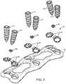
- FIG. 2is a top perspective exploded view of an anterior cervical plate system according to the present invention.
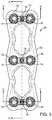
- FIG. 3is a top planar view of an anterior cervical plate system according to the present invention.
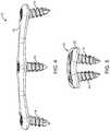
- FIG. 4is a side elevation view of an anterior cervical plate system according to the present invention.
- FIG. 5is an end elevation view of an anterior cervical plate system according to the present invention.
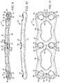
- FIG. 6is a top perspective view of a plate according to the present invention.
- FIG. 7is a top planar view of a plate according to the present invention.
- FIG. 8is a cross-sectional view taken along line A-A of FIG. 7 of plate according to the present invention.
- FIG. 9is a cross-sectional view taken along line B-B of FIG. 7 of a plate according to the present invention.
- FIG. 10is a side elevation view of a plate according to the present invention.
- FIG. 11is a bottom planar view of a plate according to the present invention.
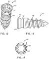
- FIG. 12is a top perspective view of a bone fastener according to the present invention.
- FIG. 13is a side elevation view of a bone fastener according to the present invention.
- FIG. 14is a top planar view of a bone fastener according to the present invention.
- FIG. 15is a top perspective view of a retention ring according to the present invention.
- FIG. 16is a top planar view of a retention ring according to the present invention.
- FIG. 17is a side elevation view of a retention ring according to the present invention.
- FIG. 18is a back end elevation view of a retention ring according to the present invention.
- FIG. 19is a front end elevation view of a retention ring according to the present invention.
- FIG. 20is a top perspective view of a locking pin according to the present invention.
- FIG. 21is a top planar view of a locking pin according to the present invention.
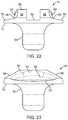
- FIG. 22is a side elevation view of a locking pin according to the present invention.
- FIG. 23is a side elevation view taken 90 degrees to FIG. 22 of a locking pin according to the present invention.
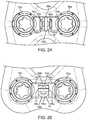
- FIG. 24is a top sectional view of an anterior cervical plate system with a locking pin in an unlocked position according to the present invention.
- FIG. 25is a cross-sectional view taken along line C-C of FIG. 3 of an anterior cervical plate system with the locking pin in an unlocked position according to the present invention.
- FIG. 26is a top sectional view of an anterior cervical plate system with a locking pin in a locked position according to the present invention.
- FIG. 27is a cross-sectional view taken along line B-B of FIG. 3 of an anterior cervical plate system with the locking pin in a locked position according to the present invention.
- FIG. 28is a top perspective sectional view of the anterior cervical plate system with a locking pin in a locked position according to the present invention.
- FIG. 29is a flow chart illustrating a method of securing the cervical plate system according to the present invention to the cervical spine of a patient.
- FIGS. 1-5depict a cervical plate system 10 according to one variation of the invention that may be used to stabilize or fuse vertebral bodies in the cervical or other region of the spine.
- the anterior cervical plate system 10that is shown in FIGS. 1-5 is a two-level bone fixation plate that is configured to span across and fixate three vertebrae of the cervical spine although the cervical plate system 10 may be a single level or any multilevel anterior cervical plate spanning two or more vertebral bodies.
- the anterior cervical plate system 10comprises a plate 12 having fasteners 14 passed through retention rings 16 locked into place with locking pins 18 .
- the plate 12includes an upper surface 20 or anterior surface that faces the patient's soft tissue and esophagus when installed and a lower surface 22 or posterior surface facing the vertebral bodies to be immobilized.
- the upper surface 20 and lower surface 22are interconnected by curved side walls and end walls to form a generally rectangular shape that is symmetrical about a midline.
- the gently curved structure of the rectangular plate 12complements the natural curved structure of the vertebral bodies and lordotic curvature of the cervical spine.
- the corners of the plateare rounded to reduce or eliminate irritation of the esophagus and the surrounding tissue.
- the plate 12is sized and shaped for use on an anterior aspect of the cervical spine although one skilled in the art may use the device in other regions of the spine and other skeletal fixations.
- the plate 12which resides atop the vertebral bodies, has a low profile as seen in FIG. 10 so as to minimally impinge on adjacent tissues.
- the plate 12 and other components of the cervical plate system 10are made from suitable biocompatible material such as stainless steel, titanium and or any other metal or metal alloy.
- One or more componentsmay be made of non-metal materials including but not limited to polymer, carbon reinforced polyetheretherketone (PEEK) or one or more biocompatible ceramics.
- the plate 12may be additionally configured to promote bone ingrowth to the plate such as a portion of the plate being made of porous material or being roughened by mechanical blasting or plasma spraying with metal particles of one or more sizes.
- the plate 12may also be coated with bio-active material, therapeutic agents for enhancing bone fusion and ingrowth, bone morphogenic proteins, growth factors and the like.
- the plate 12includes a plurality of through holes 24 extending through the cervical plate 12 from the upper surface 20 and through the lower surface 22 .
- the holes 24are configured to receive bone fasteners 14 passed there through.
- Each hole 24includes a head-receiving portion 26 near the upper surface 20 connected to a smaller shank-receiving portion 28 near the lower surface 22 to, thereby, in one variation, provide a seat for the head portion of the fastener 14 at a ledge 29 formed at the intersection of the head-receiving portion 26 and shank-receiving portion 28 .
- the head-receiving portion 26is recessed from the top surface 20 as best seen in FIGS.
- the head-receiving portion 26also provides a receiving well for the retention ring 16 . Accordingly, the head-receiving portion 26 is shaped to complement the shape of the retention ring 16 .
- the head-receiving portion 26forms a part-spherical seat or curved surface configured for a complimentary part-spherical or curved outer surface of the retention ring 16 .
- the size of the through hole 24is configured such that the head-receiving portion 26 and shank-receiving portion 28 are both large enough to allow a bone fastener 14 to pass all the way through the plate without the presence of a retention ring 16 and wherein the presence of the retention ring 16 in the through hole 24 reduces the size of the through hole 24 such that the head portion of the fastener 14 is not allowed to pass through the retention ring 16 .
- the shank-receiving portion 28 of the through hole 24is smaller than the head-receiving portion 26 without the presence of a retention ring 16 such that the head portion of a fastener 14 is not allowed to pass into the shank-receiving portion 28 of the through hole 24 and wherein the presence of the retention ring 16 further reduces the opening at the head-receiving portion 26 of the through hole 24 .
- a notch 32is formed in at least one of the head-receiving portion 26 and shank-receiving portion 28 . The notch 32 prevents the retaining ring 16 from rotating or moving out of place with respect to the plate 12 .
- the notch 32creates space within which the neck and flange of the retention ring 16 may move and flex as will be discussed in greater detail below.
- An undercut (not shown) in the through hole 24such as in the location of the head-receiving portion 26 may be formed and configured to mate with the retention ring 16 to, thereby, couple the retention ring 16 to the through hole 24 as the retention ring 16 is compressed and then inserted into or under the undercut.
- the through hole 24is slightly elliptical in shape that matches a slightly elliptical retention ring 16 which can be inserted in the conforming direction and then rotated into a non-conforming orientation to be retained within the through hole 24 by compression fit engagement therewith.
- FIGS. 6-12depict a plate 12 having three sets or three pairs of fastener through holes 24 spaced-apart along the plate centerline for driving fasteners 14 into and stabilizing three vertebral bodies for creating a two-level construct.
- Each set of fastener through holes 24includes two holes 24 spaced apart from each other along the centerline of the anterior cervical plate 12 .
- Each set or pair of through holes 24is adapted for receiving two fasteners 14 to be driven into a single vertebral body.
- the longitudinal axes 25 of a pair of through holes 24diverge relative to each other such that a pair of fasteners 14 placed therein diverge slightly relative to each other at a desired angled as best seen in FIG. 5 .
- the plate 12further includes a recess 34 located between the through holes 24 of each pair of through holes 24 .
- the recess 34is configured for receiving a locking pin 18 such that the locking pin 18 does not protrude from the upper surface 20 of the plate 12 in order to maintain the desired low profile.
- a locking pin aperture 36is formed in the recess 34 at the centerline for coupling the locking pin 18 to the plate 12 .
- the plate 12also includes two larger openings 38 located between each pair of through holes 24 that effectively reduce the overall weight of the plate 12 and provide a visualization pathway to monitor bone graft progress between the vertebral bodies.
- an exemplary orthopedic fastener 14that is preferably used with the cervical plate system 10 of the present invention is a bone screw 14 .
- the bone screw 14includes a screw head 40 , neck 42 and threaded shank 44 .
- the head 40includes a ledge 47 which is a flat surface along at least a portion of the perimeter of screw head 40 .
- the head 40includes an instrument recess 46 for receiving a complementary tip of a surgical tool.
- a substantially hexagonal, daisy-shaped recess 46is shown in FIGS. 12-14 ; however, the recess 46 can be of any shape that allows a surgical tool to drive the bone screws 14 into the vertebral column.
- the head 40 of the bone screw 14corresponds to the shape of the inside of the associated retention ring 16 or, in an alternative variation, to the shape of the head-receiving portion 26 of the through hole 24 .
- Various bone screws 14may be employed including ones capable of polyaxial, variable angle or fixed angled orientation with respect to the plate 12 with or without the ability to be locked down at a desired angle or orientation with respect to the plate 12 .
- the bone screws 14are preferably self-tapping, however, other screws requiring holes to be drilled or pre-tapped can also be employed.
- the retention ring 16has a circular or slightly elliptical profile and a central aperture 48 having a central axis and defining an entry opening at a top surface of the retention ring 16 and an exit opening at the bottom surface of the retention ring 16 .
- the retention ring 16is configured for insertion into and being received inside a through hole 24 of the plate 12 .
- the central aperture 48has a width greater than the width of the threaded shank 44 of a bone screw 14 where the width is the major diameter of the threads or, in an alternative variation, greater than the width of the minor diameter of the threads.
- the width of the central aperture 48is not larger than the width of the head of a fastener 14 such that the head 40 of the fastener is not allowed to completely pass through the central aperture 48 .
- the head 40is received at the inner surface 49 of the retention ring 16 , which is sized to prevent lateral movement of the fastener 14 and shaped to complement the shape of the screw head 40 .
- the inner surface 49 of the retention ring 16forms a part-spherical or curved seat configured for multi-angular articulation with a complimentary part-spherical or curved surface of the screw head 40 of fastener 14 .
- the complementary surfaces of the retention ring 16 and screw head 40are not limited to being part-spherical or curved but may be of any shape.
- the inner surface 49 of the retention ring 16generally slopes upwardly from the bottom surface to the top surface of the retention ring 16 .
- a plurality of slots 50are formed in the ring 16 .
- the slots 50extend approximately halfway from the top surface of the ring 16 toward the bottom surface of the ring 16 .
- the slots 50form a plurality of circumferential tabs at the upper surface around the central aperture 49 .
- These slots 50weaken the upper portion of the ring 16 such that the retention ring 16 is slightly compressible.
- the compressibility of the ring 16affords advantages for increasing the purchase of the screw head 40 to the plate 12 in addition to allowing the retention ring 16 to be inserted and retained in the plate 12 .
- the retention ring 16is easily inserted into the head-receiving portion 26 which serves as a well for the retention ring 16 .
- the retention ring 16may include an externally protruding annular retention lip (not shown) that would snap into an undercut or the like formed in the plate 12 and configured for connecting the retention ring 16 to the plate 12 .
- the tabsare deflected slightly inwardly towards the central axis upon insertion into a through hole 24 wherein the inwardly deflected tabs advantageously create an undercut for retaining the screw head 40 firmly inside the plate 12 through hole 24 .
- the slightly inwardly deflected tabsserve as fingers grasping and contacting slightly over and around at least a portion of the screw head 40 .
- a retention flange 54extending upwardly from the top surface of the ring 16 is a retention flange 54 connected to a neck 52 .
- the retention flange 54includes a portion that projects inwardly towards the center of the ring 16 and is selectively imposed into the pathway of a fastener 14 .
- the retention flange 54extends into the projection of the entry opening of the central aperture 48 such that a fastener 14 moving into and through the central aperture 48 would encounter resistance from the retention flange 54 .
- the retention flange 54includes a scalloped portion 56 that serves as a ramp for guiding a bone fastener 14 and for receiving a lateral force component exerted by the fastener 14 onto the retention flange 54 as a bone fastener 14 passes into the central aperture 48 and into the through hole 24 .
- the neck 52is adapted to flex causing the retention flange 54 to deflect slightly outwardly to allow a bone fastener 14 to continue to pass through the central aperture 48 .
- the retention flange 54is configured to snap back to its normal un-flexed or partially flexed position such that at least a portion of the retention flange 54 projects back inwardly toward the center of the ring 16 and into the pathway of the fastener 14 thereby, forming a stop that prevents the fastener 14 from backing out.
- the undersurface 55 of the retention flange 54overlays the head 40 of the fastener 14 either touching the head 40 of the fastener 14 or laying spaced apart from the head 40 of the fastener 14 and, thereby, preventing the fastener 14 from backing out.
- the snapping back of the retention flange 54 as a screw ledge 47 passes beyond the retention flange 54advantageously provides the surgeon with an audible and/or haptic signal or feedback that the screw 14 has been advanced far enough and the surgeon can stop driving or advancing the screw 14 into the vertebral bone.
- the audible or haptic clicknotifies the surgeon that the screw 14 is in position and prevents the surgeon from applying too much torque.
- the inner facing surface 57 of the retention flange 54is curved to match the curvature of the fastener 14 and configured to cover a portion of the ledge 47 along the perimeter of the screw head 40 .
- the retention ring 16is integrally formed with the plate 12 such that a neck 52 and retention flange 54 project from a surface of the plate 12 .
- the locking pin 18includes a main body 58 connected to a post 60 .
- the post 60extends from the bottom surface 72 of the main body 58 along the longitudinal axis of the locking pin 18 .
- the post 60is configured to be inserted into the locking pin aperture 36 of the plate 12 and connected to the plate 12 such that the locking pin 18 can rotate relative to the plate 12 about the longitudinal axis.
- the locking pin 18may include an additional coupling element (not shown) for coupling the locking pin 18 to the cervical plate 12 in a manner that maintains the locking pin 18 rotatably coupled to the plate 12 .
- the locking pin 18is not limited to rotational movement with respect to the plate 12 and can be designed for linear movement with respect to the plate 12 for example. Whereas the post 60 is inserted into the plate 12 , the main body 58 of the locking pin 18 resides above the upper surface 20 of the plate 12 in the location of the recess 34 next to a through hole 24 or in another variation as shown in the figures in the location of the recess 34 between two adjacent through holes 24 such that the main body 58 of the locking pin 18 does not extend beyond the outer profile of the plate 12 maintaining the smooth low profile of the plate 12 .
- the locking pin 18is shown in the figures to have a circular top profile, however, the invention is not so limited and the locking pin 18 may be any operable shape.
- the locking pin 18is means for locking or unlocking the retention flange 54 of the retention ring 16 .
- the locking pin 18includes a camming surface 66 and a blocking surface 68 formed in the main body 58 .
- the locking pin 18is positioned next to the retention ring 16 such that the camming surface 66 and blocking surface 68 in turn contact at least a portion of the neck 52 and/or at least a portion of the retention flange 54 of the stationary retention flange 54 .
- the camming surface 66is adjacent to the blocking surface 68 on the main body 58 and configured such that, with rotation of the locking pin 18 , at least a portion of the neck 52 and/or at least a portion of the retention flange 54 that is in contact with a the camming surface 66 is led into or cammed into being in contact with the blocking surface 68 to lock the retention flange 54 in position.
- a stop(not shown) may be formed at the end of the blocking surface 68 to prevent further rotation of the locking pin 18 in the same direction.
- the locking pin 18is located between two adjacent retention rings 16 a, 16 b and the locking pin 18 is configured with two oppositely disposed camming surfaces 66 a, 66 b and two oppositely disposed blocking surfaces 68 a, 68 b for locking or unlocking the retention flanges 54 a, 54 b of two adjacent retention rings 16 a, 16 b simultaneously.
- a first camming surface 66 ais adjacent to a first blocking surface 68 a and the second camming surface 66 b is adjacent to the second blocking surface 68 b and configured such that, with rotation of the locking pin 18 , at least a portion of the neck 52 and/or at least a portion of a first retention flange 54 a of a first retention ring 16 a that is in contact with the first camming surface 66 a is led or cammed into being in contact with the first blocking surface 68 a and at least a portion of the neck 52 and/or at least a portion of a second retention flange 54 b of a second retention ring 16 b that is in contact with the second camming surface 66 b is led or cammed into being in contact with the second blocking surface 68 b to lock the retention flanges 54 a, 54 b of the first and second retention rings 16 a, 16 b simultaneously.
- Stopsmay be formed at the end of each blocking surface 68 a, 68 b to prevent further rotation in the same direction. Rotation of the locking pin 18 in the opposite direction will result in the retention flanges 54 a, 54 b that are in contact with the blocking surfaces 68 a, 68 b, respectively, being in contact with the camming surfaces 66 a, 66 b, respectively, to simultaneously unlock the retention flanges 54 a, 54 b, respectively.
- the locking pinneed only be rotated by 90 degrees to move from an unlocked position to a locked position or from a locked position to an unlocked position.
- the main body 58further includes a slit 62 configured to receive an instrument, such as a screwdriver, to turn the locking pin 18 with respect to the plate 12 .
- a slit 62that is configured to match a flat screwdriver is shown in FIGS. 20-23 , a recess having any shape that is complementary to the instrument employed to activate, move or rotate the locking pin 18 may be used.
- the main body 58includes two scallops 64 a, 64 b located on either side of the slit 62 .
- a camming surface 66is formed in the location of each scallop 64 .
- the locking pin 18is configured to be disposed in the cervical plate 12 adjacent to a pair of through holes 24 and configured to simultaneously lock two adjacent retention rings 16 residing in the pair of adjacent through holes 24 as discussed above.
- the locking pin 18includes a first camming surface 66 a at the first scallop 64 a and a second camming surface 66 b at the second scallop 64 b configured to simultaneously cam against two adjacent retention rings 16 a, 16 b.
- the camming surface 66comprises a gently curved, or angled, wedge-like surface having a thickness that varies along the top surface 70 of the wedge.
- the bottom of the wedgecoincides with the bottom surface 72 of the main body 58 and is substantially planar.
- the camming surface 66 a of a wedge at the first sidevaries along the outer perimeter and is the thinnest at a location 90 degrees to the slit 62 as best seen in FIG. 23 .
- the wedgeincreases in thickness along the perimeter in a direction toward 0 degrees and 180 degrees as can be clearly seen in FIG. 22 .
- the thickness of the camming surface 66 aalso increases toward the longitudinal axes of the locking pin 18 .
- the camming surface 66 b of a wedge at the second sideis the thinnest at a location 270 degrees to the slit 62 .
- the wedgeincreases in thickness in a direction towards 180 degrees and 360 degrees as can also be seen in FIG. 23 .
- the thickness of the camming surface 66 balso increases toward the longitudinal axes of the locking pin 18 .
- the camming surface 66is sized and configured such that, upon assembly of the plate system 10 , at least a portion of the camming surface 66 is positioned underneath a portion of the retention flange 54 that extends outwardly beyond the perimeter of the retention ring 16 as best seen in FIGS. 25 and 27 .
- the camming surface 66is angled or curved to cam underneath or against the retention flange 54 and/or neck 52 .
- the locking pin 18includes two camming surfaces 66 a, 66 b
- at least a portion of each camming surface 66 a, 66 bis positioned underneath each retention flange 54 a, 54 b of the pair with each camming surface 66 a, 66 b being angled or curved to cam underneath or against the retention flanges 54 a, 54 b and/or necks 52 a, 52 b as best seen in FIGS. 25 and 27 .
- the portion of the camming surface 66 that is in contact with the retention ring 16is the thinnest and, with rotation of the locking pin 16 in a clockwise or counterclockwise direction, the portion of the camming surface 66 that is in contact with the retention ring 16 increases in thickness.
- the camming surface 66does not contact the retention ring at 90 degrees.
- the portions of the camming surfaces 66 a, 66 b at a location 90 and 270 degrees, respectively, from the slit 62are the thinnest and, with rotation of the locking pin 16 in a clockwise or counterclockwise direction, the portions of the camming surfaces 66 a, 66 b that are in contact with the retention rings 16 a, 16 b, respectively, increase in thickness.
- the camming surfaces 66 a, 66 bdo not contact the retention rings 16 a, 16 b at 90 and 270 degrees.
- the thickness of the camming surface 66increases to contact with the retention ring 16 at the neck 52 and/or at the retention flange 54 .
- Continued rotation of the locking pin 18results in the camming surface 66 camming against the neck 52 and/or retention flange 54 and moving or deflecting the retention flange 54 inwardly towards the center of the central aperture 48 or towards the central axis of the central aperture 48 .
- the camming surface 66contacts or cams against at least a portion of the undersurface 55 of the retention flange 54 that lies beyond the outside perimeter of the retention ring 16 .
- the camming surface 66exerts a force on the retention flange 54 flexing the neck 52 inwardly and deflecting the flange 54 inwardly toward the center of the central aperture 48 .
- the blocking surface 68is adjacent to or abuts at least a portion of the retention flange 54 and/or neck 52 .
- the neck 52 of the retention ring 16comes into alignment with the slit 62 of the locking pin 18 and is no longer biased or pushed inwardly by the camming surface 66 beyond the unbiased position of the retention flange 54 and neck 52 and therefore, the retention flange 54 is allowed to snap back into its normal position at which point the outer surface 53 of the retention flange 54 is adjacent to or abuts the blocking surface 68 and the blocking surface 68 thereby creating a stop for the retention flange 54 that does not allow the retention flange 54 or neck 52 to flex outwardly and out of the path of fastener 14 that may be backing out.
- the retention flange 54is deflected inwardly beyond a normal undeflected position to contact and cover at least a portion of the screw head 40 . In another variation, the retention flange 54 is deflected inwardly beyond a normal undeflected position to contact, cover and additionally exert a force on at least a portion of the screw head 40 to prevent an inserted bone screw 14 from backing out. The retention flange 54 is maintained in a locked position with the locking pin turned through at least 90 degrees of rotation.
- the snapping back of the retention flange 54 against the blocking surface 68 or into a normal unbiased, undeflected positionadvantageously provides the surgeon with haptic and/or audible feedback notifying the surgeon that sufficient rotation of the locking pin 18 is achieved and that a locked relationship of the locking pin 18 with the retention ring 16 is established.
- Rotation of the locking pin 16 in the opposite direction or continued rotation in the same directionwill result in the camming surface 66 contacting the retention flange 54 freeing it to flex out of the path of a fastener 14 to achieve an unlocked relationship of the locking pin 18 and retention ring 16 as shown in FIGS. 24 and 25 .
- a portion of the undersurface 55 of the retention flange 54may have a shape that is complementary to the camming surface 66 .
- the portion of the undersurface 55 that lies outside the outer perimeter of the retention ring 16may be angled or curved to facilitate the camming of the undersurface 55 against the camming surface 66 .
- the portion of the undersurface 55 that lies inside the outer perimeter of the retention ring 16may be configured to contact and closely cover the bone fastener 14 .
- the cervical plate system 10is assembled by first inserting the locking pins 18 into the locking pin apertures 36 located between each pair of through holes 24 .
- the locking pins 18are secured to the plate 12 such that the locking pins 18 are permitted to move or rotate with respect to the plate 12 .
- An additional coupling mechanismmay be employed to connect to the post 60 of the locking pin 18 from the lower surface 22 of the plate 12 .
- the retention rings 16are inserted into the through holes 24 of the plate 12 . As mentioned above, each retention ring 16 is slightly compressible due to the slots 50 formed in the upper surface of the ring 16 .
- the retention rings 16are compressed and inserted into the through holes 24 and then allowed to expand in the screw head-receiving portion 26 of the through hole 24 being retained in the through hole 24 by way of a friction fit engagement.
- the retention ring 16may include an annular lip extending radially outwardly and configured to engage with a complementary shaped undercut formed in the plate 12 to connect the retention ring 16 to the plate 12 .
- the through hole 24is slightly elliptical in shape that matches a slightly elliptical retention ring 16 which can be inserted in a conforming direction and then rotated into a non-conforming orientation with respect to the through hole 24 to be retained within the through hole 24 by a compression fit engagement.
- the tabsare deflected slightly inwardly towards the central axes upon insertion of the retention ring 16 into a through hole 24 wherein the inwardly deflected tabs advantageously create an undercut for retaining the screw head 40 firmly inside the plate 12 through hole 24 .
- the camming surface 66is sized and configured such that, upon assembly of the plate system 10 , at least a portion of the camming surface 66 is positioned underneath the retention flange 54 of the retention ring 16 . If a locking pin 18 is configured to lock two adjacent retention rings 16 , then at least a portion of both camming surfaces 66 a, 66 b are positioned underneath or adjacent to the retention flanges 54 a, 54 b. After the retention rings 16 are inserted into the plate 12 , the plate 12 is ready to be implanted into the patient.
- FIG. 29is a process flow diagram illustrating a method of performing a surgical procedure employing the cervical plate system 10 of the present invention.
- the anterior cervical plate 12is placed or attached adjacent to a vertebral column.
- the placement of the plate 12 relative to the vertebral bone in a patientmay be pre-operatively determined based on a pre-operative examination of the patient's spine using non-invasive imaging techniques known in the art. Any additional preparation or work may be done on and around the desired vertebrae prior to positioning the plate 12 .
- bone fasteners 14are inserted into adjacent through holes 24 of the plate 12 in step 104 while the adjacent locking pin 18 is in an unlocked position.
- an instrumentis inserted into the instrument recess 46 of the fastener 12 and the fastener 12 is driven or screwed into the desired bone in step 106 .
- each bone fastener 14passes into a through hole 24 , it encounters the retention flange 54 and deflects the retention flange 54 outwardly until the head 40 of the fastener 14 or, in particular, the ledge 47 of the screw head 40 has traveled past the retention flange 54 .
- the retention flange 54snaps back such that the retention flange 54 partially overlays or covers the fastener head 40 .
- the retention flange 54will cover or overlay the fastener ledge 47 .
- the snapping-back of the retention flange 54 onto the fastener head 40advantageously provides an audible clicking sound or clicking feeling to the surgeon signaling that the fastener 14 is properly seated and need not be driven further into the vertebral bone in step 108 . Without this signal to the surgeon, the surgeon may continue to drill the fastener 14 into the bone which may detrimentally affect implantation. Further feedback is provided to the surgeon in that the locking pin 18 cannot be moved into the locked position until and unless at least a portion of the screw head 40 has been fully inserted such that the screw head 40 , in particular, the ledge 47 of the screw head 40 is disposed distally of the retention flange 54 .
- the feedbackmay also be visual as a result of the surgeon observing the position of the retention flange 54 relative to the screw 14 making sure that the retention flange 54 overlays a portion of the screw 14 .
- the retention flange 54may be colored to enhance visual feedback.
- Another advantageis that the fastener head 40 is seated in the screw head-receiving portion 26 of the plate 12 against a slightly compressible retention ring 16 .
- the slightly compressible retention ring 16advantageously increases purchase of the fastener 14 to the plate 12 by bearing or dampening various anatomical forces imposed onto the fastener 14 instead of directly transmitting such forces undampened to the plate 12 and from the plate 12 to other weaker portions of the vertebral anatomy.
- the tabsare deflected slightly inwardly towards the central axes upon insertion of the retention ring 16 into a through hole 24 creating a reduced-diameter entry way or undercut for the screw head 40 advantageously covering the screw head 40 in finger-like fashion to retain the screw 14 in place.
- the locking pin 18is rotated in step 110 .
- an instrumentis inserted into the slit 62 or recess of the locking pin 18 and the locking pin 18 is rotated from an unlocked position as shown in FIGS. 24-25 to a locked position as shown in FIGS. 26-28 .
- Rotation of the locking pin 18is terminated when the blocking surfaces 68 a, 68 b are adjacent to or abut the adjacent retention flanges 54 a, 54 b or until a click is heard or felt by the surgeon in step 112 .
- the locking pin 18is rotated 90 degrees from the unlocked position to the locked position, however, the invention is not so limited and the locking pin 18 may be rotated anywhere between approximately 30 degrees and 330 degrees into a locked position.
- the camming surface 66deflects the retention flange 54 inwardly toward the center of the retaining ring 16 . This inward deflection of the retention flange 54 advantageously displaces any tissue or bone fragments that may interfere with the retention flange 54 effectively covering the bone screw 14 .
- the inward deflection of the retention flange 54 by the blocking surface 68results in the retention flange 54 contacting and covering at least a portion of the screw head 40 exerting a force onto the screw head 40 .
- This featureadvantageously prevents the bone screw 14 from loosening before migrating back out of the through hole 40 and keeps the screw 40 inside the through hole 40 .
- Feedbackis provided to the surgeon in that the locking pin 18 cannot be moved into the locked position until and unless the screw head 40 has been fully inserted such that the screw head 40 , in particular, the ledge 47 of the screw head 40 is disposed distally of the retention flange 54 .
- the feedbackmay also be visual, the result of the surgeon observing the position of the locking pin 18 relative to the retention flange 54 .
- the slit 62may be colored to enhance visual feedback.
- the same instrumentis used to rotate the locking pin 18 from a locked position to an unlocked position in which the blocking surface 68 is not adjacent to or does not abut the retention flange 54 and the retention flange 54 is free to flex outwardly with respect to the retention ring 16 .
- an instrumentcan be inserted into the instrument recess 46 on the screw head 40 to remove the bone screw 14 .
- Using the instrument to back out the screw 14results in the screw head 40 camming against the retention flange 54 deflecting it outwardly and out of the pathway of the screw 14 being removed.
- an additional instrumentmay be employed to keep the retention flange 54 flexed in the outward position while the bone screw 14 is backed out of the bone.
Landscapes
- Health & Medical Sciences (AREA)
- Orthopedic Medicine & Surgery (AREA)
- Life Sciences & Earth Sciences (AREA)
- Surgery (AREA)
- Neurology (AREA)
- Heart & Thoracic Surgery (AREA)
- Engineering & Computer Science (AREA)
- Biomedical Technology (AREA)
- Nuclear Medicine, Radiotherapy & Molecular Imaging (AREA)
- Medical Informatics (AREA)
- Molecular Biology (AREA)
- Animal Behavior & Ethology (AREA)
- General Health & Medical Sciences (AREA)
- Public Health (AREA)
- Veterinary Medicine (AREA)
- Surgical Instruments (AREA)
- Prostheses (AREA)
Abstract
Description
Claims (20)
Priority Applications (2)
| Application Number | Priority Date | Filing Date | Title |
|---|---|---|---|
| US15/904,983US10912591B2 (en) | 2011-07-19 | 2018-02-26 | Anterior cervical plate |
| US17/143,627US11478283B2 (en) | 2011-07-19 | 2021-01-07 | Anterior cervical plate |
Applications Claiming Priority (5)
| Application Number | Priority Date | Filing Date | Title |
|---|---|---|---|
| US13/185,641US8668723B2 (en) | 2011-07-19 | 2011-07-19 | Anterior cervical plate |
| US14/158,995US9101407B2 (en) | 2011-07-19 | 2014-01-20 | Anterior cervical plate |
| US14/453,458US9113964B2 (en) | 2011-07-19 | 2014-08-06 | Anterior cervical plate |
| US14/804,866US9918749B2 (en) | 2011-07-19 | 2015-07-21 | Anterior cervical plate |
| US15/904,983US10912591B2 (en) | 2011-07-19 | 2018-02-26 | Anterior cervical plate |
Related Parent Applications (1)
| Application Number | Title | Priority Date | Filing Date |
|---|---|---|---|
| US14/804,866ContinuationUS9918749B2 (en) | 2011-07-19 | 2015-07-21 | Anterior cervical plate |
Related Child Applications (1)
| Application Number | Title | Priority Date | Filing Date |
|---|---|---|---|
| US17/143,627ContinuationUS11478283B2 (en) | 2011-07-19 | 2021-01-07 | Anterior cervical plate |
Publications (2)
| Publication Number | Publication Date |
|---|---|
| US20180185071A1 US20180185071A1 (en) | 2018-07-05 |
| US10912591B2true US10912591B2 (en) | 2021-02-09 |
Family
ID=47556299
Family Applications (6)
| Application Number | Title | Priority Date | Filing Date |
|---|---|---|---|
| US13/185,641Active2031-10-04US8668723B2 (en) | 2011-07-19 | 2011-07-19 | Anterior cervical plate |
| US14/158,995ActiveUS9101407B2 (en) | 2011-07-19 | 2014-01-20 | Anterior cervical plate |
| US14/453,458ActiveUS9113964B2 (en) | 2011-07-19 | 2014-08-06 | Anterior cervical plate |
| US14/804,866ActiveUS9918749B2 (en) | 2011-07-19 | 2015-07-21 | Anterior cervical plate |
| US15/904,983Expired - Fee RelatedUS10912591B2 (en) | 2011-07-19 | 2018-02-26 | Anterior cervical plate |
| US17/143,627Active2031-11-16US11478283B2 (en) | 2011-07-19 | 2021-01-07 | Anterior cervical plate |
Family Applications Before (4)
| Application Number | Title | Priority Date | Filing Date |
|---|---|---|---|
| US13/185,641Active2031-10-04US8668723B2 (en) | 2011-07-19 | 2011-07-19 | Anterior cervical plate |
| US14/158,995ActiveUS9101407B2 (en) | 2011-07-19 | 2014-01-20 | Anterior cervical plate |
| US14/453,458ActiveUS9113964B2 (en) | 2011-07-19 | 2014-08-06 | Anterior cervical plate |
| US14/804,866ActiveUS9918749B2 (en) | 2011-07-19 | 2015-07-21 | Anterior cervical plate |
Family Applications After (1)
| Application Number | Title | Priority Date | Filing Date |
|---|---|---|---|
| US17/143,627Active2031-11-16US11478283B2 (en) | 2011-07-19 | 2021-01-07 | Anterior cervical plate |
Country Status (1)
| Country | Link |
|---|---|
| US (6) | US8668723B2 (en) |
Cited By (3)
| Publication number | Priority date | Publication date | Assignee | Title |
|---|---|---|---|---|
| USD1004776S1 (en) | 2022-01-20 | 2023-11-14 | Mirus Llc | Cervical plate |
| USD1039696S1 (en) | 2022-09-08 | 2024-08-20 | Mirus Llc | Bone plate |
| USD1041008S1 (en) | 2022-09-06 | 2024-09-03 | Mirus Llc | Bone plate |
Families Citing this family (51)
| Publication number | Priority date | Publication date | Assignee | Title |
|---|---|---|---|---|
| EP2224868B1 (en)* | 2007-11-21 | 2014-07-30 | Globus Medical, Inc. | Cervical spine stabilization system with extendable plates |
| US8668723B2 (en) | 2011-07-19 | 2014-03-11 | Neurostructures, Inc. | Anterior cervical plate |
| US10149707B2 (en)* | 2011-08-17 | 2018-12-11 | Globus Medical, Inc. | Bone fixation plate system and method |
| US9351768B2 (en)* | 2011-08-26 | 2016-05-31 | Life Spine, Inc. | Bone screw retention in a spinal implant |
| US8852248B2 (en)* | 2012-01-13 | 2014-10-07 | A.M. Surgical, Inc. | Cross pin fixator for bone fragments and use thereof |
| US9642652B2 (en)* | 2013-02-13 | 2017-05-09 | Choice Spine, Lp | Variable angle bone plate with semi-constrained articulating screw |
| FR3005565B1 (en)* | 2013-05-17 | 2016-08-26 | Euros Sa | BONE SCREW FOR SECURE ARTHRODESIS DEVICE |
| KR101599603B1 (en) | 2013-08-26 | 2016-03-03 | 경북대학교 산학협력단 | Medical inserting apparatus |
| US9468479B2 (en) | 2013-09-06 | 2016-10-18 | Cardinal Health 247, Inc. | Bone plate |
| US20150094774A1 (en)* | 2013-10-02 | 2015-04-02 | Karl W. Swann | Bone fixation assembly, including s-shaped resilient lock for screw locking clips |
| US9629664B2 (en) | 2014-01-20 | 2017-04-25 | Neurostructures, Inc. | Anterior cervical plate |
| WO2015123693A1 (en)* | 2014-02-14 | 2015-08-20 | Spectrum Spine Ip Holdings, Llc | Cervical minimal access fusion system |
| KR101537062B1 (en)* | 2014-08-11 | 2015-07-16 | 주식회사 코렌텍 | An apparatus for fixing vertebra |
| TWI578951B (en)* | 2014-08-15 | 2017-04-21 | A-Spine Asia Co Ltd | A window plate device which is fixed after rotation |
| US10213237B2 (en) | 2014-10-03 | 2019-02-26 | Stryker European Holdings I, Llc | Periprosthetic extension plate |
| US10350053B2 (en)* | 2014-10-14 | 2019-07-16 | Avinash Kumar | Muscle tissue anchor plate |
| US11504174B2 (en)* | 2014-11-10 | 2022-11-22 | Meditech Spine, Llc | Polyaxial bone plate and locking assembly |
| KR101639887B1 (en) | 2014-11-11 | 2016-07-14 | 경북대학교 산학협력단 | A system for fixing cervical vertebrae and a driver used for an appratus for fixing cervical vertebrae |
| KR101608949B1 (en)* | 2014-11-19 | 2016-04-04 | 경북대학교 산학협력단 | A system for fixing cervical vertebrae, an appratus for fixing cervical vertebrae and a driver used for an appratus for fixing cervical vertebrae |
| AU2016200179B2 (en) | 2015-01-14 | 2020-09-17 | Stryker European Operations Holdings Llc | Spinal implant with porous and solid surfaces |
| CA2930123A1 (en) | 2015-05-18 | 2016-11-18 | Stryker European Holdings I, Llc | Partially resorbable implants and methods |
| KR101670768B1 (en) | 2015-07-16 | 2016-10-31 | 경북대학교 산학협력단 | Screw anchor assembly |
| EP3329870B1 (en)* | 2015-07-27 | 2023-08-02 | CG Bio Co., Ltd. | Apparatus for fixing cervical spine |
| US10874445B2 (en) | 2015-10-13 | 2020-12-29 | Kyungpook National University Industry-Academic Cooperation Foundation | Screw fixing apparatus |
| WO2017096098A1 (en) | 2015-12-01 | 2017-06-08 | Revivo Medical, Llc | Bone fixation apparatus with fastener securement mechanism and methods of use |
| KR101712610B1 (en) | 2015-12-29 | 2017-03-06 | 경북대학교 산학협력단 | A rod connecter |
| US10456181B2 (en)* | 2016-01-12 | 2019-10-29 | Globus Medical, Inc. | Spinal plate assembly having locking mechanism |
| US10251685B2 (en) | 2016-03-17 | 2019-04-09 | Stryker European Holdings I, Llc | Floating locking insert |
| KR101791004B1 (en) | 2016-06-08 | 2017-10-27 | 경북대학교 산학협력단 | Screw anchor assembly and a method for using the same to pedicle screw instrumentation |
| US10016224B2 (en)* | 2016-10-14 | 2018-07-10 | Neurostructures, Inc. | Anterior cervical plate |
| US10512547B2 (en) | 2017-05-04 | 2019-12-24 | Neurostructures, Inc. | Interbody spacer |
| US10980641B2 (en) | 2017-05-04 | 2021-04-20 | Neurostructures, Inc. | Interbody spacer |
| WO2018237322A1 (en)* | 2017-06-22 | 2018-12-27 | Alliance Partners Llc | MEDICAL IMPLANT HAVING A MULTI-MODE LOCKING MECHANISM AND METHOD OF USE |
| EP3459502B1 (en) | 2017-09-20 | 2024-05-22 | Stryker European Operations Holdings LLC | Spinal implants |
| US11272963B2 (en) | 2017-11-16 | 2022-03-15 | Globus Medical, Inc. | Anterior cervical plate assembly |
| US11304734B2 (en) | 2017-11-16 | 2022-04-19 | Globus Medical Inc. | Anterior cervical plate assembly |
| US11234742B2 (en) | 2017-11-16 | 2022-02-01 | Globus Medical, Inc. | Anterior cervical plate assembly |
| US11229460B2 (en) | 2017-11-16 | 2022-01-25 | Globus Medical, Inc. | Anterior cervical plate assembly |
| CN108635034B (en)* | 2018-07-20 | 2020-03-17 | 河北医科大学第三医院 | Structure for anterior cervical decompression |
| US11076892B2 (en) | 2018-08-03 | 2021-08-03 | Neurostructures, Inc. | Anterior cervical plate |
| US11071629B2 (en) | 2018-10-13 | 2021-07-27 | Neurostructures Inc. | Interbody spacer |
| WO2020181211A1 (en)* | 2019-03-07 | 2020-09-10 | Spinal Surgical Strategies, Llc | Bone graft delivery system and method for using same |
| EP3738535B1 (en)* | 2019-05-09 | 2024-07-10 | Globus Medical, Inc. | Anterior cervical plate assembly |
| CN110123433A (en)* | 2019-05-15 | 2019-08-16 | 山东新华联合骨科器材股份有限公司 | A kind of internal fixing system for anterior cervical vertebrae |
| US10743922B1 (en) | 2019-09-27 | 2020-08-18 | Trilliant Surgical Llc | Variable angle locking construct for orthopedic applications |
| US11229464B2 (en)* | 2019-12-04 | 2022-01-25 | Medos International Sarl | Apparatus for driver-specific backout prevention |
| US11382761B2 (en) | 2020-04-11 | 2022-07-12 | Neurostructures, Inc. | Expandable interbody spacer |
| US11304817B2 (en) | 2020-06-05 | 2022-04-19 | Neurostructures, Inc. | Expandable interbody spacer |
| USD949341S1 (en) | 2020-09-29 | 2022-04-19 | Trilliant Surgical Llc | Bone fixation plate |
| US11717419B2 (en) | 2020-12-10 | 2023-08-08 | Neurostructures, Inc. | Expandable interbody spacer |
| US11298159B1 (en) | 2021-01-05 | 2022-04-12 | Meditech Spine, Llc | Polyaxial bone plate and locking assembly |
Citations (192)
| Publication number | Priority date | Publication date | Assignee | Title |
|---|---|---|---|---|
| US5364399A (en) | 1993-02-05 | 1994-11-15 | Danek Medical, Inc. | Anterior cervical plating system |
| US5549612A (en) | 1992-11-25 | 1996-08-27 | Codman & Shurtleff, Inc. | Osteosynthesis plate system |
| US5616142A (en) | 1994-07-20 | 1997-04-01 | Yuan; Hansen A. | Vertebral auxiliary fixation device |
| US6045552A (en) | 1998-03-18 | 2000-04-04 | St. Francis Medical Technologies, Inc. | Spine fixation plate system |
| US6139550A (en) | 1997-02-11 | 2000-10-31 | Michelson; Gary K. | Skeletal plating system |
| US6258089B1 (en) | 1998-05-19 | 2001-07-10 | Alphatec Manufacturing, Inc. | Anterior cervical plate and fixation system |
| US6261291B1 (en) | 1999-07-08 | 2001-07-17 | David J. Talaber | Orthopedic implant assembly |
| US6398783B1 (en) | 1997-02-11 | 2002-06-04 | Sulzer Spine-Tech Inc. | Multi-lock anterior cervical plate |
| US20020120270A1 (en) | 2001-02-28 | 2002-08-29 | Hai Trieu | Flexible systems for spinal stabilization and fixation |
| US20030093082A1 (en) | 2000-06-26 | 2003-05-15 | Stryker Spine | Bone screw retaining system |
| US20030105462A1 (en) | 2001-11-30 | 2003-06-05 | Haider Thomas T. | Poly axial cervical plate system |
| US20030105467A1 (en) | 2001-11-30 | 2003-06-05 | Ralph James D. | Distraction instrument for use in anterior cervical fixation surgery |
| US20030105466A1 (en) | 2001-11-30 | 2003-06-05 | Ralph James D. | Spacer device and insertion instrument for use in anterior cervical fixation surgery |
| US20030125739A1 (en) | 2001-12-12 | 2003-07-03 | Bagga Charanpreet S. | Bioactive spinal implants and method of manufacture thereof |
| US20030135216A1 (en) | 2000-05-25 | 2003-07-17 | Sevrain Lionel C. | Anchoring system for fixing objects to bones |
| US6599290B2 (en) | 2001-04-17 | 2003-07-29 | Ebi, L.P. | Anterior cervical plating system and associated method |
| US6602255B1 (en) | 2000-06-26 | 2003-08-05 | Stryker Spine | Bone screw retaining system |
| US6605090B1 (en) | 2000-10-25 | 2003-08-12 | Sdgi Holdings, Inc. | Non-metallic implant devices and intra-operative methods for assembly and fixation |
| US20030153920A1 (en) | 2002-02-13 | 2003-08-14 | Ralph James D. | Longitudinal plate assembly having an adjustable length |
| US20030171753A1 (en) | 2001-10-25 | 2003-09-11 | Corin Limited | Surgical implant |
| US20030187509A1 (en) | 2002-04-01 | 2003-10-02 | Lemole G. Michael | Modulus plating system and method |
| US20030187442A1 (en) | 2002-03-12 | 2003-10-02 | Marc Richelsoph | Bone plate and screw retaining mechanism |
| US6629998B1 (en) | 2000-08-23 | 2003-10-07 | Chih-I Lin | Intervertebral retrieval device |
| US6652525B1 (en) | 1998-04-30 | 2003-11-25 | Sofamor S.N.C. | Anterior implant for the spine |
| US20030229348A1 (en) | 2000-05-25 | 2003-12-11 | Sevrain Lionel C. | Auxiliary vertebrae connecting device |
| US20030236528A1 (en) | 2002-06-24 | 2003-12-25 | Thramann Jeffrey J | Impactor for use with cervical plate |
| US20040015169A1 (en)* | 2002-07-16 | 2004-01-22 | Larry Gause | Bone plate fastener retaining mechanisms and methods |
| US20040019353A1 (en) | 2002-02-01 | 2004-01-29 | Freid James M. | Spinal plate system for stabilizing a portion of a spine |
| US20040024081A1 (en) | 2001-02-22 | 2004-02-05 | Trieu Hai H. | Bioactive nanocomposites and methods for their use |
| US20040030336A1 (en) | 2002-08-06 | 2004-02-12 | Khanna Rohit Kumar | Anterior cervical spine stabilization method and system |
| US20040034352A1 (en) | 2002-08-16 | 2004-02-19 | Needham Dusty Anna | Systems, instrumentation and techniques for retaining fasteners relative to a bone plate |
| US20040049279A1 (en) | 2000-05-25 | 2004-03-11 | Sevrain Lionel C. | Inter-vertebral disc prosthesis for rachis through anterior surgery thereof |
| US20040068319A1 (en) | 2002-10-04 | 2004-04-08 | Cordaro Nicholas M. | Cervical plate/screw system for immobilizing vertebral bodies |
| US20040087951A1 (en) | 2002-11-04 | 2004-05-06 | Khalili Farid Bruce | Fastener retention system |
| US20040092947A1 (en) | 2002-09-30 | 2004-05-13 | Foley Kevin T. | Devices and methods for securing a bone plate to a bony segment |
| US20040092929A1 (en) | 2002-09-27 | 2004-05-13 | Zindrick Michael R. | Spinal plate with means to secure a graft |
| US20040097938A1 (en) | 2002-07-24 | 2004-05-20 | Neville Alleyne | Compressible fixation apparatus for spinal surgery |
| US20040097925A1 (en) | 2002-06-07 | 2004-05-20 | Boehm Frank H. | Cervical spine stabilizing system and method |
| US20040097950A1 (en) | 1999-10-13 | 2004-05-20 | Foley Kevin T. | System and method for securing a plate to a spinal column |
| US20040097934A1 (en) | 1997-05-15 | 2004-05-20 | Farris Robert A. | Anterior cervical plating system |
| US6743256B2 (en) | 2000-10-11 | 2004-06-01 | Michael D. Mason | Graftless spinal fusion device |
| EP1429675A1 (en) | 2001-08-24 | 2004-06-23 | Sulzer Spine-Tech Inc. | Bone fixation device |
| US6755833B1 (en) | 2001-12-14 | 2004-06-29 | Kamaljit S. Paul | Bone support assembly |
| US20040127900A1 (en)* | 2002-12-31 | 2004-07-01 | Konieczynski David D. | Resilient bone plate and screw system allowing bi-directional assembly |
| US20040127897A1 (en) | 2000-01-06 | 2004-07-01 | Jim Freid | System and method for stabilizing the human spine with a bone plate |
| US20040127899A1 (en) | 2002-12-31 | 2004-07-01 | Konieczynski David D. | Bone plate and screw system allowing bi-directional attachment |
| US20040133205A1 (en) | 2002-06-24 | 2004-07-08 | Jeffrey Thramann | Cervical plate |
| US20040177847A1 (en) | 2003-03-10 | 2004-09-16 | Foley Kevin T. | Posterior pedicle screw and plate system and methods |
| US20040181229A1 (en) | 2001-06-04 | 2004-09-16 | Michelson Gary K. | Instrumentation for use with dynamic single-lock anterior cervical plate system having non-detachably fastened and moveable segments |
| US20040181226A1 (en) | 2001-06-04 | 2004-09-16 | Michelson Gary K. | Method for installing dynamic, modular, single-lock anterior cervical plate system having assembleable and moveable segments |
| US6793658B2 (en) | 2001-04-06 | 2004-09-21 | Society De Fabrication De Material Orthopedique, S.A. | Anterior plating system and method |
| US20040186476A1 (en) | 2001-06-06 | 2004-09-23 | Michelson Gary K. | Method for installing dynamic, modular, multilock anterior cervical plate system having detachably fastened assembleable and moveable segments |
| US20040204713A1 (en) | 2003-01-10 | 2004-10-14 | Abdou M. Samy | Plating system for bone fixation and subsidence and method of implantation |
| US20040204710A1 (en) | 2003-04-09 | 2004-10-14 | Tushar Patel | Drill guide and plate inserter |
| US20040204712A1 (en) | 2003-04-09 | 2004-10-14 | Eric Kolb | Bone fixation plates |
| US20040210314A1 (en) | 2000-07-10 | 2004-10-21 | Michelson Gary K. | Flanged interbody spinal fusion implants |
| US20040215195A1 (en) | 2003-04-25 | 2004-10-28 | Sdgi Holdings, Inc. | Non-metallic orthopedic plate |
| US20040215192A1 (en) | 2000-03-01 | 2004-10-28 | Justis Jeff R | Superelastic spinal stabilization system and method |
| US20040220571A1 (en) | 1998-04-30 | 2004-11-04 | Richard Assaker | Bone plate assembly |
| US20040225290A1 (en) | 2001-03-27 | 2004-11-11 | Nuvasive, Inc. | Hinged anterior thoracic/lumbar plate |
| US20040236333A1 (en) | 2003-03-21 | 2004-11-25 | Lin Paul S. | Uniplate cervical device |
| US20040243128A1 (en) | 2001-05-17 | 2004-12-02 | Howland Robert S. | Selective axis posterior lumbar spinal plating fixation apparatus and methods for use |
| US20040260306A1 (en) | 2003-06-20 | 2004-12-23 | Fallin T. Wade | Method and apparatus for bone plating |
| US20050015093A1 (en) | 2003-07-16 | 2005-01-20 | Suh Sean S. | Plating system with compression drill guide |
| US20050027296A1 (en) | 2002-06-24 | 2005-02-03 | Jeffrey Thramann | Cervical plate with backout protection |
| US20050033298A1 (en) | 2001-10-31 | 2005-02-10 | Ortho Development Corporation | Cervical plate for stabilizing the human spine |
| US20050043732A1 (en) | 2003-08-18 | 2005-02-24 | Dalton Brian E. | Cervical compression plate assembly |
| US20050059970A1 (en) | 2003-09-17 | 2005-03-17 | Eric Kolb | Bone fixation systems |
| EP1520545A1 (en) | 2003-10-01 | 2005-04-06 | SDGI Holdings, Inc. | Spinal device locking mechanism |
| US20050075633A1 (en) | 2003-10-02 | 2005-04-07 | Thomas Ross | Anterior cervical plate |
| US20050085816A1 (en) | 2001-06-04 | 2005-04-21 | Michelson Gary K. | Method for installation of dynamic anterior cervical plate system having moveable segments |
| US20050137597A1 (en) | 2003-12-22 | 2005-06-23 | Life Spine | Dynamic cervical plates and cervical plate constructs |
| US20050149021A1 (en) | 2003-12-23 | 2005-07-07 | Tozzi James E. | Spinal implant device |
| US20050171551A1 (en) | 2003-10-21 | 2005-08-04 | William Sukovich | Instrument and method for preparing a bone to receive an implant |
| US20050177163A1 (en) | 2003-12-29 | 2005-08-11 | Abdou M. S. | Plating system for bone fixation and method of implantation |
| US20050177161A1 (en) | 2004-02-10 | 2005-08-11 | Baynham Bret O. | Static anterior cervical plate |
| US20050177160A1 (en) | 2004-02-10 | 2005-08-11 | Baynham Bret O. | Dynamic cervical plate |
| US20050187551A1 (en) | 2002-12-02 | 2005-08-25 | Orbay Jorge L. | Bone plate system with bone screws fixed by secondary compression |
| US20050187554A1 (en) | 2001-06-04 | 2005-08-25 | Michelson Gary K. | Method for installation of anterior cervical plate system having vertebral body engaging anchors and connecting plate |
| US20050192576A1 (en) | 2001-06-06 | 2005-09-01 | Michelson Gary K. | Method for installing dynamic multilock anterior cervical plate system having detachably fastened and moveable segments |
| US20050209593A1 (en) | 2004-03-06 | 2005-09-22 | Depuy Spine, Inc. | Flexible anterior cervical plate |
| US20050208095A1 (en) | 2003-11-20 | 2005-09-22 | Angiotech International Ag | Polymer compositions and methods for their use |
| US20050228386A1 (en) | 2004-04-08 | 2005-10-13 | Tara Ziolo | Bone fixation device |
| US20050234455A1 (en) | 2004-04-19 | 2005-10-20 | Lawrence Binder | Bone fixation plate |
| US20050261690A1 (en) | 2004-04-19 | 2005-11-24 | Binder Lawrence J | Bone fixation plate |
| US20050277938A1 (en) | 2004-05-27 | 2005-12-15 | Depuy Spine, Inc. | Tri-joint implant methods |
| US20050283152A1 (en)* | 2004-06-17 | 2005-12-22 | Lindemann Gary S | Method and apparatus for retaining screws in a plate |
| US20060009845A1 (en) | 2004-07-08 | 2006-01-12 | Chin Kingsley R | Method and device for kinematic retaining cervical plating |
| US20060030852A1 (en) | 2002-11-13 | 2006-02-09 | Sevrain Lionel C | Anchoring system for fixing objects to bones |
| US7008426B2 (en) | 2001-12-14 | 2006-03-07 | Paul Kamaljit S | Bone treatment plate assembly |
| US20060079961A1 (en) | 2001-01-23 | 2006-04-13 | Michelson Gary K | Implant with trailing end adapted to receive bone screws |
| US20060082015A1 (en) | 2004-09-30 | 2006-04-20 | Inion Ltd. | Surgical implant shaping instrument, surgical system and method |
| US7070599B2 (en) | 2002-07-24 | 2006-07-04 | Paul Kamaljit S | Bone support assembly |
| US20060149251A1 (en) | 2004-12-22 | 2006-07-06 | Tara Ziolo | Bone fixation system |
| US20060149256A1 (en) | 1997-08-04 | 2006-07-06 | Wagner Erik J | System and method for stabilizing the human spine with a bone plate |
| US20060155298A1 (en) | 2003-03-07 | 2006-07-13 | Theken Surgical, Llc | Instrument guide and implant holder |
| US20060161157A1 (en) | 2004-02-26 | 2006-07-20 | Lawrence Mosca | Bone plate system and methods |
| US20060167456A1 (en) | 2004-12-21 | 2006-07-27 | Packaging Service Corporation Of Kentucky | Cervical plate system |
| US20060189997A1 (en) | 2005-02-10 | 2006-08-24 | Zimmer Spine, Inc. | All through one drill guide for cervical plating |
| US20060200134A1 (en) | 2002-02-01 | 2006-09-07 | James Freid | Spinal plate system for stabilizing a portion of a spine |
| US20060200147A1 (en) | 2005-02-18 | 2006-09-07 | Ensign Michael D | Orthopedic plate system and method for using the same |
| US20060229620A1 (en) | 2005-03-03 | 2006-10-12 | Accin Corporation | Method and apparatus for providing a retainer for a bone stabilization device |
| US20060235405A1 (en) | 2005-03-31 | 2006-10-19 | Hawkes David T | Active compression orthopedic plate system and method for using the same |
| US20060241611A1 (en) | 2005-04-12 | 2006-10-26 | Frank Castro | Modular spinal implant system to assist with cervical stabilization |
| US20060241616A1 (en) | 2002-12-31 | 2006-10-26 | Depuy Spine, Inc. | Bone Plate and Resilient Screw System Allowing Bi-Directional Assembly |
| US20060276792A1 (en) | 2005-05-25 | 2006-12-07 | Ensign Michael D | Low profile pedicle screw and rod assembly |
| US20060287653A1 (en) | 2005-06-15 | 2006-12-21 | Stryker Spine | Anterior cervical plate |
| US7186254B2 (en) | 2002-02-25 | 2007-03-06 | Dinh Dzung H | Methods and apparatus for promoting fusion of vertebrae |
| WO2007037774A1 (en) | 2005-04-26 | 2007-04-05 | Innovative Spinal Design | Dynamic cervical plate |
| US20070083203A1 (en) | 2005-09-16 | 2007-04-12 | Ribeiro Helio M | Anterior cervical plating system |
| WO2007056516A2 (en) | 2005-11-09 | 2007-05-18 | Abdou M S | Bone fixation systems and methods of implantation |
| US20070185489A1 (en) | 2006-01-26 | 2007-08-09 | Abdou M S | Devices and Methods for Inter-Vertebral Orthopedic Device Placement |
| US20070203492A1 (en) | 1999-10-13 | 2007-08-30 | Needham Dusty A | Anterior cervical plating system and method |
| WO2007101266A1 (en) | 2006-03-01 | 2007-09-07 | Warsaw Orthopedic, Inc. | Low profile spinal rod connector system |
| US20070213729A1 (en) | 2006-03-08 | 2007-09-13 | Sdgi Holdings, Inc. | Flexible bone plates and methods for dynamic spinal stabilization |
| US20070213728A1 (en) | 2006-03-07 | 2007-09-13 | Sdgi Holdings, Inc. | Methods and devices for retaining bone plate anchors |
| WO2007103081A2 (en) | 2006-03-02 | 2007-09-13 | The Cleveland Clinic Foundation | Asymmetrical cervical fusion plate and method for use |
| US20070213820A1 (en) | 2003-04-23 | 2007-09-13 | Sepitec Foundation | Spondylodesis Device |
| US7273481B2 (en) | 2002-10-28 | 2007-09-25 | Blackstone Medical, Inc. | Bone plate assembly provided with screw locking mechanisms |
| US20070225717A1 (en) | 2006-03-21 | 2007-09-27 | Hawkes David T | Cervical pop rivet locking mechanism |
| US20070225707A1 (en) | 2006-03-22 | 2007-09-27 | Sdgi Holdings, Inc. | Orthopedic spinal devices fabricated from two or more materials |
| US20070225718A1 (en) | 2006-03-22 | 2007-09-27 | Ensign Michael D | Rotolock cervical plate locking mechanism |
| US7276070B2 (en) | 2003-06-11 | 2007-10-02 | Mueckter Helmut | Osteosynthesis plate or comparable implant plus ball socket |
| US20070233072A1 (en) | 2006-03-01 | 2007-10-04 | Sdgi Holdings, Inc. | Modular fastener assemblies for spinal stabilization systems and methods |
| US20070233117A1 (en) | 2006-02-21 | 2007-10-04 | Life Spine, Llc | Structure for joining and retaining multi-part orthopedic implants |
| US20070233108A1 (en) | 2006-03-15 | 2007-10-04 | Stalcup Gregory C | Spine fixation device |
| US20070233119A1 (en) | 2006-03-10 | 2007-10-04 | Markworth Aaron D | Polyaxial occipital plate |
| US20070233107A1 (en) | 2006-02-27 | 2007-10-04 | Zielinski Steven C | Method and apparatus for lateral reduction and fusion of the spine |
| US20070233110A1 (en) | 2006-03-14 | 2007-10-04 | Nabil L. Muhanna, M.D. | Vertebral plating system |
| EP1841376A2 (en) | 2005-01-12 | 2007-10-10 | Warsaw Orthopedic, Inc. | Anchor retaining mechanisms for bone plates |
| US20070239158A1 (en) | 2006-04-10 | 2007-10-11 | Sdgi Holdings, Inc. | Elastic plates for spinal fixation or stabilization |
| EP1847229A2 (en) | 1997-02-11 | 2007-10-24 | Warsaw Orthopedic, Inc. | Single lock skeletal plating system |
| US7288094B2 (en)* | 2005-06-10 | 2007-10-30 | Sdgi Holdings, Inc. | System and method for retaining screws relative to a vertebral plate |
| US7288095B2 (en) | 2004-08-12 | 2007-10-30 | Atlas Spine, Inc. | Bone plate with screw lock |
| US7291152B2 (en) | 2003-04-18 | 2007-11-06 | Abdou M Samy | Bone fixation system and method of implantation |
| WO2007134199A2 (en) | 2006-05-10 | 2007-11-22 | Biomerix Corp | Spinal implants and devices and methods for their controlled insertion |
| US20070270851A1 (en) | 2006-04-28 | 2007-11-22 | David Erickson | Radiolucent bone plate systems and methods of use |
| US20070270965A1 (en) | 2006-04-28 | 2007-11-22 | Joe Ferguson | Orthopedic support locating or centering feature and method |
| US20070276405A1 (en) | 2002-11-19 | 2007-11-29 | Huebner Randall J | Adjustable bone plates |
| US20070276371A1 (en) | 2004-02-10 | 2007-11-29 | Baynham Bret O | Dynamic cervical plate |
| US7322984B2 (en) | 2005-01-06 | 2008-01-29 | Spinal, Llc | Spinal plate with internal screw locks |
| US20080208341A1 (en) | 2006-12-29 | 2008-08-28 | Providence Medical Technology, Inc. | Cervical distraction method |
| US20080208260A1 (en) | 2007-02-22 | 2008-08-28 | Csaba Truckai | Spine treatment devices and methods |
| US20080208262A1 (en) | 2007-02-26 | 2008-08-28 | Butler Michael S | Spine plate with bone screw relief area |
| US20080215097A1 (en) | 2006-03-30 | 2008-09-04 | Ensign Michael D | Active Compression Orthopedic Plate System and Method for Using the Same |
| US20080228226A1 (en) | 2007-03-12 | 2008-09-18 | Arya Nick Shamie | Cervical support system |
| US20080234748A1 (en) | 2007-01-31 | 2008-09-25 | Wallenstein Todd M | Anterior vertebral plate with quick lock screw |
| US20080234749A1 (en) | 2007-01-26 | 2008-09-25 | Zimmer Technology, Inc. | Bone plate providing threaded locking head screw capture |
| US20080234755A1 (en) | 2007-01-29 | 2008-09-25 | Polaris Biotechnology, Inc. | Craniospinal fusion method and apparatus |
| US20080234681A1 (en) | 2004-02-10 | 2008-09-25 | Baynham Matthew G | Dynamic cervical plate |
| US20080234751A1 (en) | 2007-01-31 | 2008-09-25 | Mcclintock Larry E | Anterior vertebral plate with closed thread screw |
| US20080234680A1 (en) | 2007-01-26 | 2008-09-25 | Structure Medical, Inc. | Interlock for dynamic bone fixation plates |
| US20080234753A1 (en) | 2007-03-19 | 2008-09-25 | Warsaw Orthopedic, Inc. | Spinal Stabilization Systems |
| US20080234752A1 (en) | 2007-03-21 | 2008-09-25 | The University Of North Carolina At Chapel Hill | Surgical plate puller devices and methods for use with surgical bone screw/plate systems |
| US20080234750A1 (en) | 2007-01-31 | 2008-09-25 | Woods Richard W | Anterior vertebral plate with taper lock screw |
| US20080234689A1 (en) | 2007-02-21 | 2008-09-25 | Warsaw Orthopedic, Inc. | Vertebral Plate Measuring Device and Method of Use |
| US7438715B2 (en) | 2005-01-06 | 2008-10-21 | Spinal Llc | Spinal implant kit |
| US7452370B2 (en) | 2005-04-29 | 2008-11-18 | Warsaw Orthopedic, Inc | Apparatus for retaining a bone anchor in a bone plate and method for use thereof |
| US20080287999A1 (en) | 2007-05-18 | 2008-11-20 | Markworth Aaron D | Anterior cervical plate with independent spring-loaded locking slides for each screw |
| US20080288001A1 (en) | 2007-05-18 | 2008-11-20 | Trace Cawley | Cervical plate locking mechanism and associated surgical method |
| US20090131988A1 (en)* | 2007-11-09 | 2009-05-21 | Stryker Spine | Cervical plate with a feedback device for selective association with bone screw blocking mechanism |
| US20090149888A1 (en) | 2007-12-07 | 2009-06-11 | Custom Spine, Inc. | Orthopedic anti back-out mechanism |
| US20090177239A1 (en) | 2007-08-06 | 2009-07-09 | Michael Castro | Cervical plate instrument kit |
| US20090177237A1 (en) | 2008-01-04 | 2009-07-09 | Spartek Medical, Inc. | Cervical spine implant system and method |
| WO2009089395A2 (en) | 2008-01-08 | 2009-07-16 | Polaris Biotechnology, Inc. | Osteointegration apparatus |
| US20090182383A1 (en) | 2008-01-14 | 2009-07-16 | Amedica Corporation | Bone fixation plate with anchor retaining member |
| US20090182341A1 (en) | 2002-03-12 | 2009-07-16 | Cervitech, Inc. | Instrument set for fitting an intervertebral jont prosthesis |
| US20090187218A1 (en) | 2008-01-17 | 2009-07-23 | Amedica Corporation | Bone fixation plate with wire members for resisting back out of bone anchors |
| WO2009091775A2 (en) | 2008-01-17 | 2009-07-23 | Warsaw Orthopedic, Inc. | Intervertebral cage and vertebral fusion device |
| WO2009091770A1 (en) | 2008-01-17 | 2009-07-23 | Warsaw Orthopedic, Inc. | Spinal osteosynthesis device |
| US20090192549A1 (en) | 2008-01-30 | 2009-07-30 | Ebi, Llc | Bone plating system |
| US20090210008A1 (en) | 2008-02-20 | 2009-08-20 | Life Spine, Inc. | Modular spine plate with projection and socket interface |
| US20090222049A1 (en) | 2005-11-16 | 2009-09-03 | Robert Frigg | Device for Bone Fixation with at least one Through Hole |
| US7601170B2 (en) | 2004-12-13 | 2009-10-13 | Kyphon Sarl | Inter-cervical facet implant and method |
| US20090270926A1 (en) | 2008-04-24 | 2009-10-29 | Hawkes David T | Rotolock cervical plate locking mechanism |
| US20100016901A1 (en) | 2005-06-16 | 2010-01-21 | Robinson James C | Bone screw retaining system |
| US7662174B2 (en) | 2005-01-06 | 2010-02-16 | Spinal, Llc | Spinal plate with screw locks and cam locks |
| US20100042159A1 (en) | 2008-07-17 | 2010-02-18 | Alphatec Spine, Inc. | Bone plate assembly |
| US20100049256A1 (en) | 2007-01-30 | 2010-02-25 | Dong Myung Jeon | Anterior cerivcal plating system |
| US20100234897A1 (en) | 2009-03-13 | 2010-09-16 | Lanx, Inc. | Spinal plate assemblies with backout protection cap and methods |
| US7857839B2 (en) | 2003-09-03 | 2010-12-28 | Synthes Usa, Llc | Bone plate with captive clips |
| US20110029023A1 (en) | 2009-07-30 | 2011-02-03 | Clariance | Slide-type anti-backout device for prosthesis |
| US20110106159A1 (en) | 2008-06-05 | 2011-05-05 | Seaspine, Inc. | Spinal fixation plate assembly |
| US20110118784A1 (en) | 2004-02-10 | 2011-05-19 | Baynham Bret O | Cervical Plate Ratchet Pedicle Screws |
| US20110172666A1 (en) | 2010-01-08 | 2011-07-14 | Heilman Benjamin P | Variable angle locking screw |
| US7985242B2 (en) | 2002-10-30 | 2011-07-26 | Zimmer Spine, Inc. | Instruments and methods for reduction of vertebral bodies |
| US8419777B2 (en) | 2009-07-24 | 2013-04-16 | Spinal Usa, Inc. | Bone plate screw-blocking systems and methods |
| US20130184767A1 (en) | 2012-01-17 | 2013-07-18 | Josh Kaufman | Spinal Plate And Locking Screw Devices, Methods, And Systems |
| US8562656B2 (en) | 2010-10-15 | 2013-10-22 | Warsaw Orrthopedic, Inc. | Retaining mechanism |
| US8591556B2 (en) | 2011-07-19 | 2013-11-26 | Globus Medical, Inc. | Locking confirmation mechanism for a bone screw and plate assembly |
| US8668723B2 (en) | 2011-07-19 | 2014-03-11 | Neurostructures, Inc. | Anterior cervical plate |
| US9265531B2 (en) | 2012-06-05 | 2016-02-23 | Blackstone Medical, Inc. | Orthopedic devices with a locking mechanism |
Family Cites Families (4)
| Publication number | Priority date | Publication date | Assignee | Title |
|---|---|---|---|---|
| US8821554B2 (en)* | 2008-11-10 | 2014-09-02 | Amendia, Inc. | Method, system, and apparatus for mammalian bony segment stabilization |
| US8940030B1 (en)* | 2011-01-28 | 2015-01-27 | Nuvasive, Inc. | Spinal fixation system and related methods |
| EP3329870B1 (en)* | 2015-07-27 | 2023-08-02 | CG Bio Co., Ltd. | Apparatus for fixing cervical spine |
| US11304734B2 (en)* | 2017-11-16 | 2022-04-19 | Globus Medical Inc. | Anterior cervical plate assembly |
- 2011
- 2011-07-19USUS13/185,641patent/US8668723B2/enactiveActive
- 2014
- 2014-01-20USUS14/158,995patent/US9101407B2/enactiveActive
- 2014-08-06USUS14/453,458patent/US9113964B2/enactiveActive
- 2015
- 2015-07-21USUS14/804,866patent/US9918749B2/enactiveActive
- 2018
- 2018-02-26USUS15/904,983patent/US10912591B2/ennot_activeExpired - Fee Related
- 2021
- 2021-01-07USUS17/143,627patent/US11478283B2/enactiveActive
Patent Citations (273)
| Publication number | Priority date | Publication date | Assignee | Title |
|---|---|---|---|---|
| US5549612A (en) | 1992-11-25 | 1996-08-27 | Codman & Shurtleff, Inc. | Osteosynthesis plate system |
| US5616144A (en) | 1992-11-25 | 1997-04-01 | Codman & Shurtleff, Inc. | Osteosynthesis plate system |
| US5364399A (en) | 1993-02-05 | 1994-11-15 | Danek Medical, Inc. | Anterior cervical plating system |
| US5616142A (en) | 1994-07-20 | 1997-04-01 | Yuan; Hansen A. | Vertebral auxiliary fixation device |
| US20030181912A1 (en) | 1997-02-11 | 2003-09-25 | Michelson Gary K. | Anterior cervical plating system and bone screw |
| US6139550A (en) | 1997-02-11 | 2000-10-31 | Michelson; Gary K. | Skeletal plating system |
| US20030191472A1 (en) | 1997-02-11 | 2003-10-09 | Michelson Gary K. | Multilock anterior cervical plating system |
| US20030191471A1 (en) | 1997-02-11 | 2003-10-09 | Michelson Gary K. | Multilock anterior cervical plating system |
| US6398783B1 (en) | 1997-02-11 | 2002-06-04 | Sulzer Spine-Tech Inc. | Multi-lock anterior cervical plate |
| US20050187552A1 (en) | 1997-02-11 | 2005-08-25 | Michelson Gary K. | Multilock anterior cervical plating system |
| US20050059971A1 (en) | 1997-02-11 | 2005-03-17 | Michelson Gary K. | Plating system having retaining member that permits movement of at least one bone fastener |
| US20040122426A1 (en) | 1997-02-11 | 2004-06-24 | Michelson Gary K. | Bone plate having a portion adapted to overlie a fastener |
| US20050038436A1 (en) | 1997-02-11 | 2005-02-17 | Michelson Gary K. | System and method for stabilizing a portion of the spine |
| EP1847229A2 (en) | 1997-02-11 | 2007-10-24 | Warsaw Orthopedic, Inc. | Single lock skeletal plating system |
| US20040236335A1 (en) | 1997-02-11 | 2004-11-25 | Michelson Gary K. | Plate apparatus for the spine |
| US20040236334A1 (en)* | 1997-02-11 | 2004-11-25 | Michelson Gary K. | Plating apparatus and system having a retaining element |
| US20040220572A1 (en) | 1997-02-11 | 2004-11-04 | Michelson Gary K | Skeletal plating system |
| US20040097934A1 (en) | 1997-05-15 | 2004-05-20 | Farris Robert A. | Anterior cervical plating system |
| US20060149256A1 (en) | 1997-08-04 | 2006-07-06 | Wagner Erik J | System and method for stabilizing the human spine with a bone plate |
| US6045552A (en) | 1998-03-18 | 2000-04-04 | St. Francis Medical Technologies, Inc. | Spine fixation plate system |
| US20110270311A1 (en) | 1998-04-30 | 2011-11-03 | Warsaw Orthopedic, Inc. | Anterior implant for the spine |
| US20040158246A1 (en) | 1998-04-30 | 2004-08-12 | Sofamor S.N.C. | Anterior implant for the spine |
| US6652525B1 (en) | 1998-04-30 | 2003-11-25 | Sofamor S.N.C. | Anterior implant for the spine |
| US20040220571A1 (en) | 1998-04-30 | 2004-11-04 | Richard Assaker | Bone plate assembly |
| US20100069968A1 (en) | 1998-04-30 | 2010-03-18 | Sofamor S.N.C. | Anterior implant for the spine |
| US6626907B2 (en) | 1998-05-19 | 2003-09-30 | Alphatec Manufacturing, Inc. | Anterior cervical plate and fixation system |
| US6258089B1 (en) | 1998-05-19 | 2001-07-10 | Alphatec Manufacturing, Inc. | Anterior cervical plate and fixation system |
| USRE43008E1 (en) | 1999-07-08 | 2011-12-06 | Acantha, Inc. | Orthopedic implant assembly |
| US6261291B1 (en) | 1999-07-08 | 2001-07-17 | David J. Talaber | Orthopedic implant assembly |
| US20040097950A1 (en) | 1999-10-13 | 2004-05-20 | Foley Kevin T. | System and method for securing a plate to a spinal column |
| US20070203492A1 (en) | 1999-10-13 | 2007-08-30 | Needham Dusty A | Anterior cervical plating system and method |
| US6964664B2 (en) | 2000-01-06 | 2005-11-15 | Spinal Concepts Inc. | System and method for stabilizing the human spine with a bone plate |
| US20040127897A1 (en) | 2000-01-06 | 2004-07-01 | Jim Freid | System and method for stabilizing the human spine with a bone plate |
| US20040215192A1 (en) | 2000-03-01 | 2004-10-28 | Justis Jeff R | Superelastic spinal stabilization system and method |
| US20030135216A1 (en) | 2000-05-25 | 2003-07-17 | Sevrain Lionel C. | Anchoring system for fixing objects to bones |
| US20040006343A1 (en) | 2000-05-25 | 2004-01-08 | Sevrain Lionel C. | Auxiliary vertebrae connecting device |
| US20030229348A1 (en) | 2000-05-25 | 2003-12-11 | Sevrain Lionel C. | Auxiliary vertebrae connecting device |
| US20040049279A1 (en) | 2000-05-25 | 2004-03-11 | Sevrain Lionel C. | Inter-vertebral disc prosthesis for rachis through anterior surgery thereof |
| US7887547B2 (en) | 2000-06-26 | 2011-02-15 | Stryker Spine | Bone screw retaining system |
| US20030093082A1 (en) | 2000-06-26 | 2003-05-15 | Stryker Spine | Bone screw retaining system |
| US20050149027A1 (en) | 2000-06-26 | 2005-07-07 | Stryker Spine | Bone screw retaining system |
| US6602255B1 (en) | 2000-06-26 | 2003-08-05 | Stryker Spine | Bone screw retaining system |
| US20040210314A1 (en) | 2000-07-10 | 2004-10-21 | Michelson Gary K. | Flanged interbody spinal fusion implants |
| US6629998B1 (en) | 2000-08-23 | 2003-10-07 | Chih-I Lin | Intervertebral retrieval device |
| US6743256B2 (en) | 2000-10-11 | 2004-06-01 | Michael D. Mason | Graftless spinal fusion device |
| US20070213828A1 (en) | 2000-10-25 | 2007-09-13 | Trieu Hai H | Non-metallic implant devices and intra-operative methods for assembly and fixation |
| US6605090B1 (en) | 2000-10-25 | 2003-08-12 | Sdgi Holdings, Inc. | Non-metallic implant devices and intra-operative methods for assembly and fixation |
| US20060079961A1 (en) | 2001-01-23 | 2006-04-13 | Michelson Gary K | Implant with trailing end adapted to receive bone screws |
| US20040106924A1 (en) | 2001-02-15 | 2004-06-03 | Ralph James D. | Longitudinal plate assembly having an adjustable length |
| US20040024081A1 (en) | 2001-02-22 | 2004-02-05 | Trieu Hai H. | Bioactive nanocomposites and methods for their use |
| US20020120270A1 (en) | 2001-02-28 | 2002-08-29 | Hai Trieu | Flexible systems for spinal stabilization and fixation |
| US20080228230A1 (en) | 2001-03-27 | 2008-09-18 | Nuvasive, Inc. | Hinged Bone Plate and Related Methods |
| US20040225290A1 (en) | 2001-03-27 | 2004-11-11 | Nuvasive, Inc. | Hinged anterior thoracic/lumbar plate |
| US6793658B2 (en) | 2001-04-06 | 2004-09-21 | Society De Fabrication De Material Orthopedique, S.A. | Anterior plating system and method |
| US20030208204A1 (en) | 2001-04-17 | 2003-11-06 | Bailey Kirk J. | Anterior cervical plating system |
| US6599290B2 (en) | 2001-04-17 | 2003-07-29 | Ebi, L.P. | Anterior cervical plating system and associated method |
| US20050216005A1 (en) | 2001-05-17 | 2005-09-29 | Howland Robert S | Selective axis anchor screw posterior lumbar plating system |
| US20040243128A1 (en) | 2001-05-17 | 2004-12-02 | Howland Robert S. | Selective axis posterior lumbar spinal plating fixation apparatus and methods for use |
| US20110054528A1 (en) | 2001-06-04 | 2011-03-03 | Michelson Gary K | Dynamic plate system having moveable segments |
| US20050027297A1 (en) | 2001-06-04 | 2005-02-03 | Michelson Gary K. | Dynamic, modular, single-lock anterior cervical plate system having assembleable and moveable segments and instrumentation for installation thereof |
| US20060085001A1 (en) | 2001-06-04 | 2006-04-20 | Michelson Gary K | Plate system having bone portion engaging anchors and connecting plate |
| US20050187554A1 (en) | 2001-06-04 | 2005-08-25 | Michelson Gary K. | Method for installation of anterior cervical plate system having vertebral body engaging anchors and connecting plate |
| US7824432B2 (en) | 2001-06-04 | 2010-11-02 | Warsaw Orthopedic, Inc. | Method for installation of dynamic anterior cervical plate system having moveable segments |
| US20040181229A1 (en) | 2001-06-04 | 2004-09-16 | Michelson Gary K. | Instrumentation for use with dynamic single-lock anterior cervical plate system having non-detachably fastened and moveable segments |
| US20040181226A1 (en) | 2001-06-04 | 2004-09-16 | Michelson Gary K. | Method for installing dynamic, modular, single-lock anterior cervical plate system having assembleable and moveable segments |
| US7811285B2 (en) | 2001-06-04 | 2010-10-12 | Warsaw Orthopedic, Inc. | Dynamic, modular, single-lock anterior cervical plate system having assembleable and moveable segments and instrumentation for installation thereof |
| US20050085816A1 (en) | 2001-06-04 | 2005-04-21 | Michelson Gary K. | Method for installation of dynamic anterior cervical plate system having moveable segments |
| US7740630B2 (en) | 2001-06-04 | 2010-06-22 | Warsaw Orthopedic, Inc. | Anterior cervical plate system having vertebral body engaging anchors and connecting plate |
| US20050216010A1 (en) | 2001-06-04 | 2005-09-29 | Michelson Gary K | Method for installation of dynamic, single-lock anterior cervical plate system having non-detachably fastened and moveable segments |
| US20090259226A1 (en) | 2001-06-04 | 2009-10-15 | Michelson Gary K | Method for installation of dynamic, single-lock anterior cervical plate system having non-detachably fastened and moveable segments |
| US20040186476A1 (en) | 2001-06-06 | 2004-09-23 | Michelson Gary K. | Method for installing dynamic, modular, multilock anterior cervical plate system having detachably fastened assembleable and moveable segments |
| US7803157B2 (en) | 2001-06-06 | 2010-09-28 | Warsaw Orthopedic, Inc. | Dynamic, modular, multilock anterior cervical plate system having detachably fastened assembleable and moveable segments and instrumentation for installation thereof |
| US20050027298A1 (en) | 2001-06-06 | 2005-02-03 | Michelson Gary K. | Dynamic, modular, multilock anterior cervical plate system having detachably fastened assembleable and moveable segments and instrumentation for installation thereof |
| US20050192576A1 (en) | 2001-06-06 | 2005-09-01 | Michelson Gary K. | Method for installing dynamic multilock anterior cervical plate system having detachably fastened and moveable segments |
| US20050216009A1 (en) | 2001-06-06 | 2005-09-29 | Michelson Gary K | Instrumentation for use with dynamic multilock anterior cervical plate system having non-detachably fastened and moveable segments |
| EP1429675A1 (en) | 2001-08-24 | 2004-06-23 | Sulzer Spine-Tech Inc. | Bone fixation device |
| US20050187553A1 (en) | 2001-08-24 | 2005-08-25 | Grabowski John J. | Bone fixation device |
| US20030171753A1 (en) | 2001-10-25 | 2003-09-11 | Corin Limited | Surgical implant |
| US20050033298A1 (en) | 2001-10-31 | 2005-02-10 | Ortho Development Corporation | Cervical plate for stabilizing the human spine |
| US20040153088A1 (en) | 2001-11-30 | 2004-08-05 | Spinecore Inc. | Spacer device and insertion instrument for use in anterior cervical fixation surgery |
| US20040087945A1 (en) | 2001-11-30 | 2004-05-06 | Ralph James D. | Distraction instrument for use in anterior cervical fixation surgery |
| US20030105462A1 (en) | 2001-11-30 | 2003-06-05 | Haider Thomas T. | Poly axial cervical plate system |
| US20030105466A1 (en) | 2001-11-30 | 2003-06-05 | Ralph James D. | Spacer device and insertion instrument for use in anterior cervical fixation surgery |
| US20030105467A1 (en) | 2001-11-30 | 2003-06-05 | Ralph James D. | Distraction instrument for use in anterior cervical fixation surgery |
| US20030125739A1 (en) | 2001-12-12 | 2003-07-03 | Bagga Charanpreet S. | Bioactive spinal implants and method of manufacture thereof |
| US7008426B2 (en) | 2001-12-14 | 2006-03-07 | Paul Kamaljit S | Bone treatment plate assembly |
| US7255699B2 (en) | 2001-12-14 | 2007-08-14 | Paul Kamaljit S | Spinal plate assembly |
| US7204837B2 (en) | 2001-12-14 | 2007-04-17 | Paul Kamaljit S | Spinal plate assembly |
| US8236033B2 (en) | 2001-12-14 | 2012-08-07 | Paul Kamaljit S | Spinal plate assembly |
| US8221476B2 (en) | 2001-12-14 | 2012-07-17 | Paul Kamaljit S | Spinal plate assembly |
| US8128668B2 (en) | 2001-12-14 | 2012-03-06 | Paul Kamaljit S | Bone treatment plate assembly |
| US6755833B1 (en) | 2001-12-14 | 2004-06-29 | Kamaljit S. Paul | Bone support assembly |
| US20040019353A1 (en) | 2002-02-01 | 2004-01-29 | Freid James M. | Spinal plate system for stabilizing a portion of a spine |
| US20060200134A1 (en) | 2002-02-01 | 2006-09-07 | James Freid | Spinal plate system for stabilizing a portion of a spine |
| US20030153920A1 (en) | 2002-02-13 | 2003-08-14 | Ralph James D. | Longitudinal plate assembly having an adjustable length |
| US7186254B2 (en) | 2002-02-25 | 2007-03-06 | Dinh Dzung H | Methods and apparatus for promoting fusion of vertebrae |
| US20040097935A1 (en) | 2002-03-12 | 2004-05-20 | Marc Richelsoph | Bone plate and screw retaining mechanism |
| US20030187442A1 (en) | 2002-03-12 | 2003-10-02 | Marc Richelsoph | Bone plate and screw retaining mechanism |
| US6695846B2 (en) | 2002-03-12 | 2004-02-24 | Spinal Innovations, Llc | Bone plate and screw retaining mechanism |
| US20030187440A1 (en) | 2002-03-12 | 2003-10-02 | Marc Richelsoph | Bone plate and screw retaining mechanism |
| US20090182341A1 (en) | 2002-03-12 | 2009-07-16 | Cervitech, Inc. | Instrument set for fitting an intervertebral jont prosthesis |
| US20030187509A1 (en) | 2002-04-01 | 2003-10-02 | Lemole G. Michael | Modulus plating system and method |
| US20040097925A1 (en) | 2002-06-07 | 2004-05-20 | Boehm Frank H. | Cervical spine stabilizing system and method |
| US7175623B2 (en) | 2002-06-24 | 2007-02-13 | Lanx, Llc | Cervical plate with backout protection |
| US20040133205A1 (en) | 2002-06-24 | 2004-07-08 | Jeffrey Thramann | Cervical plate |
| US20030236528A1 (en) | 2002-06-24 | 2003-12-25 | Thramann Jeffrey J | Impactor for use with cervical plate |
| US20070233120A1 (en) | 2002-06-24 | 2007-10-04 | Lanx, Llc | Cervical plate |
| US20050027296A1 (en) | 2002-06-24 | 2005-02-03 | Jeffrey Thramann | Cervical plate with backout protection |
| US20040015169A1 (en)* | 2002-07-16 | 2004-01-22 | Larry Gause | Bone plate fastener retaining mechanisms and methods |
| US20040097938A1 (en) | 2002-07-24 | 2004-05-20 | Neville Alleyne | Compressible fixation apparatus for spinal surgery |
| US7070599B2 (en) | 2002-07-24 | 2006-07-04 | Paul Kamaljit S | Bone support assembly |
| US20040030336A1 (en) | 2002-08-06 | 2004-02-12 | Khanna Rohit Kumar | Anterior cervical spine stabilization method and system |
| US20040034352A1 (en) | 2002-08-16 | 2004-02-19 | Needham Dusty Anna | Systems, instrumentation and techniques for retaining fasteners relative to a bone plate |
| US20040092929A1 (en) | 2002-09-27 | 2004-05-13 | Zindrick Michael R. | Spinal plate with means to secure a graft |
| US20040092947A1 (en) | 2002-09-30 | 2004-05-13 | Foley Kevin T. | Devices and methods for securing a bone plate to a bony segment |
| US7220263B2 (en) | 2002-10-04 | 2007-05-22 | Seaspine, Inc. | Cervical plate/screw system for immobilizing vertebral bodies |
| US20040068319A1 (en) | 2002-10-04 | 2004-04-08 | Cordaro Nicholas M. | Cervical plate/screw system for immobilizing vertebral bodies |
| US7273481B2 (en) | 2002-10-28 | 2007-09-25 | Blackstone Medical, Inc. | Bone plate assembly provided with screw locking mechanisms |
| US7985242B2 (en) | 2002-10-30 | 2011-07-26 | Zimmer Spine, Inc. | Instruments and methods for reduction of vertebral bodies |
| US20040087951A1 (en) | 2002-11-04 | 2004-05-06 | Khalili Farid Bruce | Fastener retention system |
| US7524325B2 (en) | 2002-11-04 | 2009-04-28 | Farid Bruce Khalili | Fastener retention system |
| US20060030852A1 (en) | 2002-11-13 | 2006-02-09 | Sevrain Lionel C | Anchoring system for fixing objects to bones |
| US20070276405A1 (en) | 2002-11-19 | 2007-11-29 | Huebner Randall J | Adjustable bone plates |
| US20050187551A1 (en) | 2002-12-02 | 2005-08-25 | Orbay Jorge L. | Bone plate system with bone screws fixed by secondary compression |
| US20040127899A1 (en) | 2002-12-31 | 2004-07-01 | Konieczynski David D. | Bone plate and screw system allowing bi-directional attachment |
| US20040127900A1 (en)* | 2002-12-31 | 2004-07-01 | Konieczynski David D. | Resilient bone plate and screw system allowing bi-directional assembly |
| US20050273105A1 (en) | 2002-12-31 | 2005-12-08 | Depuy Spine, Inc. | Bone plate and screw system allowing bi-directional assembly |
| US7651517B2 (en) | 2002-12-31 | 2010-01-26 | Depuy Acromed, Inc. | Bone plate and resilient screw system allowing bi-directional assembly |
| US20060241616A1 (en) | 2002-12-31 | 2006-10-26 | Depuy Spine, Inc. | Bone Plate and Resilient Screw System Allowing Bi-Directional Assembly |
| US20040204713A1 (en) | 2003-01-10 | 2004-10-14 | Abdou M. Samy | Plating system for bone fixation and subsidence and method of implantation |
| US20060155298A1 (en) | 2003-03-07 | 2006-07-13 | Theken Surgical, Llc | Instrument guide and implant holder |
| US7278997B1 (en) | 2003-03-07 | 2007-10-09 | Theken Spine, Llc | Instrument guide and implant holder |
| US20040177847A1 (en) | 2003-03-10 | 2004-09-16 | Foley Kevin T. | Posterior pedicle screw and plate system and methods |
| US20040236333A1 (en) | 2003-03-21 | 2004-11-25 | Lin Paul S. | Uniplate cervical device |
| US20040204712A1 (en) | 2003-04-09 | 2004-10-14 | Eric Kolb | Bone fixation plates |
| US20040204710A1 (en) | 2003-04-09 | 2004-10-14 | Tushar Patel | Drill guide and plate inserter |
| US7291152B2 (en) | 2003-04-18 | 2007-11-06 | Abdou M Samy | Bone fixation system and method of implantation |
| US20070213820A1 (en) | 2003-04-23 | 2007-09-13 | Sepitec Foundation | Spondylodesis Device |
| US20040215195A1 (en) | 2003-04-25 | 2004-10-28 | Sdgi Holdings, Inc. | Non-metallic orthopedic plate |
| US7276070B2 (en) | 2003-06-11 | 2007-10-02 | Mueckter Helmut | Osteosynthesis plate or comparable implant plus ball socket |
| US20040260306A1 (en) | 2003-06-20 | 2004-12-23 | Fallin T. Wade | Method and apparatus for bone plating |
| US20050015092A1 (en) | 2003-07-16 | 2005-01-20 | Rathbun David S. | Plating system with multiple function drill guide |
| US20050015093A1 (en) | 2003-07-16 | 2005-01-20 | Suh Sean S. | Plating system with compression drill guide |
| US20050043732A1 (en) | 2003-08-18 | 2005-02-24 | Dalton Brian E. | Cervical compression plate assembly |
| US7857839B2 (en) | 2003-09-03 | 2010-12-28 | Synthes Usa, Llc | Bone plate with captive clips |
| US20050059970A1 (en) | 2003-09-17 | 2005-03-17 | Eric Kolb | Bone fixation systems |
| EP1520545A1 (en) | 2003-10-01 | 2005-04-06 | SDGI Holdings, Inc. | Spinal device locking mechanism |
| US20080021470A1 (en) | 2003-10-02 | 2008-01-24 | Zimmer Spine, Inc. | Anterior cervical plate |
| US20050075633A1 (en) | 2003-10-02 | 2005-04-07 | Thomas Ross | Anterior cervical plate |
| US7306605B2 (en) | 2003-10-02 | 2007-12-11 | Zimmer Spine, Inc. | Anterior cervical plate |
| US20050171551A1 (en) | 2003-10-21 | 2005-08-04 | William Sukovich | Instrument and method for preparing a bone to receive an implant |
| US20050208095A1 (en) | 2003-11-20 | 2005-09-22 | Angiotech International Ag | Polymer compositions and methods for their use |
| US20050137597A1 (en) | 2003-12-22 | 2005-06-23 | Life Spine | Dynamic cervical plates and cervical plate constructs |
| US20050149026A1 (en) | 2003-12-22 | 2005-07-07 | Life Spine | Static & dynamic cervical plates and cervical plate constructs |
| US7318825B2 (en) | 2003-12-22 | 2008-01-15 | Life Spine Llc | Dynamic cervical plates and cervical plate constructs |
| US20050149021A1 (en) | 2003-12-23 | 2005-07-07 | Tozzi James E. | Spinal implant device |
| US20050177163A1 (en) | 2003-12-29 | 2005-08-11 | Abdou M. S. | Plating system for bone fixation and method of implantation |
| US20070276371A1 (en) | 2004-02-10 | 2007-11-29 | Baynham Bret O | Dynamic cervical plate |
| US20110118784A1 (en) | 2004-02-10 | 2011-05-19 | Baynham Bret O | Cervical Plate Ratchet Pedicle Screws |
| US7468069B2 (en) | 2004-02-10 | 2008-12-23 | Atlas Spine, Inc. | Static anterior cervical plate |
| US20050177160A1 (en) | 2004-02-10 | 2005-08-11 | Baynham Bret O. | Dynamic cervical plate |
| US20080234681A1 (en) | 2004-02-10 | 2008-09-25 | Baynham Matthew G | Dynamic cervical plate |
| US7815666B2 (en) | 2004-02-10 | 2010-10-19 | Atlas Spine, Inc. | Dynamic cervical plate |
| US20050177161A1 (en) | 2004-02-10 | 2005-08-11 | Baynham Bret O. | Static anterior cervical plate |
| US20060161157A1 (en) | 2004-02-26 | 2006-07-20 | Lawrence Mosca | Bone plate system and methods |
| US7909859B2 (en) | 2004-02-26 | 2011-03-22 | Pioneer Surgical Technology, Inc. | Bone plate system and methods |
| US7740649B2 (en) | 2004-02-26 | 2010-06-22 | Pioneer Surgical Technology, Inc. | Bone plate system and methods |
| US20050209593A1 (en) | 2004-03-06 | 2005-09-22 | Depuy Spine, Inc. | Flexible anterior cervical plate |
| US20050228386A1 (en) | 2004-04-08 | 2005-10-13 | Tara Ziolo | Bone fixation device |
| US20050234455A1 (en) | 2004-04-19 | 2005-10-20 | Lawrence Binder | Bone fixation plate |
| US20050261690A1 (en) | 2004-04-19 | 2005-11-24 | Binder Lawrence J | Bone fixation plate |
| US8236034B2 (en) | 2004-04-19 | 2012-08-07 | Globus Medical, Inc. | Bone fixation plate |
| US20110213421A1 (en) | 2004-04-19 | 2011-09-01 | Lawrence Binder | Bone Fixation Plate |
| US7963981B2 (en) | 2004-04-19 | 2011-06-21 | Globus Medical, Inc. | Bone fixation plate |
| US20050277938A1 (en) | 2004-05-27 | 2005-12-15 | Depuy Spine, Inc. | Tri-joint implant methods |
| US20050277930A1 (en) | 2004-05-27 | 2005-12-15 | Depuy Spine, Inc. | Tri-joint implant |
| US20050283152A1 (en)* | 2004-06-17 | 2005-12-22 | Lindemann Gary S | Method and apparatus for retaining screws in a plate |
| US20060009845A1 (en) | 2004-07-08 | 2006-01-12 | Chin Kingsley R | Method and device for kinematic retaining cervical plating |
| US7288095B2 (en) | 2004-08-12 | 2007-10-30 | Atlas Spine, Inc. | Bone plate with screw lock |
| US20060082015A1 (en) | 2004-09-30 | 2006-04-20 | Inion Ltd. | Surgical implant shaping instrument, surgical system and method |
| US7601170B2 (en) | 2004-12-13 | 2009-10-13 | Kyphon Sarl | Inter-cervical facet implant and method |
| US20060167456A1 (en) | 2004-12-21 | 2006-07-27 | Packaging Service Corporation Of Kentucky | Cervical plate system |
| US20060149251A1 (en) | 2004-12-22 | 2006-07-06 | Tara Ziolo | Bone fixation system |
| US7322984B2 (en) | 2005-01-06 | 2008-01-29 | Spinal, Llc | Spinal plate with internal screw locks |
| US7438715B2 (en) | 2005-01-06 | 2008-10-21 | Spinal Llc | Spinal implant kit |
| US7662174B2 (en) | 2005-01-06 | 2010-02-16 | Spinal, Llc | Spinal plate with screw locks and cam locks |
| EP1841376A2 (en) | 2005-01-12 | 2007-10-10 | Warsaw Orthopedic, Inc. | Anchor retaining mechanisms for bone plates |
| US20060189997A1 (en) | 2005-02-10 | 2006-08-24 | Zimmer Spine, Inc. | All through one drill guide for cervical plating |
| US20060200147A1 (en) | 2005-02-18 | 2006-09-07 | Ensign Michael D | Orthopedic plate system and method for using the same |
| US20060229620A1 (en) | 2005-03-03 | 2006-10-12 | Accin Corporation | Method and apparatus for providing a retainer for a bone stabilization device |
| US8057522B2 (en) | 2005-03-03 | 2011-11-15 | Altus Partners, Llc | Methods and apparatus for providing a retainer for a bone stabilization device |
| US20090171397A1 (en) | 2005-03-03 | 2009-07-02 | Accelerated Innovation, Llc | Methods and apparatus for providing a retainer for a bone stabilization device |
| US20060235405A1 (en) | 2005-03-31 | 2006-10-19 | Hawkes David T | Active compression orthopedic plate system and method for using the same |
| US20060241611A1 (en) | 2005-04-12 | 2006-10-26 | Frank Castro | Modular spinal implant system to assist with cervical stabilization |
| WO2007037774A1 (en) | 2005-04-26 | 2007-04-05 | Innovative Spinal Design | Dynamic cervical plate |
| US7452370B2 (en) | 2005-04-29 | 2008-11-18 | Warsaw Orthopedic, Inc | Apparatus for retaining a bone anchor in a bone plate and method for use thereof |
| US20060276792A1 (en) | 2005-05-25 | 2006-12-07 | Ensign Michael D | Low profile pedicle screw and rod assembly |
| US7288094B2 (en)* | 2005-06-10 | 2007-10-30 | Sdgi Holdings, Inc. | System and method for retaining screws relative to a vertebral plate |
| US20060287653A1 (en) | 2005-06-15 | 2006-12-21 | Stryker Spine | Anterior cervical plate |
| WO2006138291A2 (en) | 2005-06-15 | 2006-12-28 | Stryker Spine | Anterior cervical plate |
| US7686806B2 (en) | 2005-06-15 | 2010-03-30 | Stryker Spine | Anterior cervical plate |
| US20100016901A1 (en) | 2005-06-16 | 2010-01-21 | Robinson James C | Bone screw retaining system |
| US7662154B2 (en) | 2005-09-16 | 2010-02-16 | Blackstone Medical, Inc. | Anterior cervical plating system |
| US20070083203A1 (en) | 2005-09-16 | 2007-04-12 | Ribeiro Helio M | Anterior cervical plating system |
| US20070123884A1 (en) | 2005-11-09 | 2007-05-31 | Abdou M S | Bone fixation systems and methods of implantation |
| WO2007056516A2 (en) | 2005-11-09 | 2007-05-18 | Abdou M S | Bone fixation systems and methods of implantation |
| US20130197588A1 (en) | 2005-11-09 | 2013-08-01 | Samy Abdou | Bone fixation systems and methods of implantation |
| US20090222049A1 (en) | 2005-11-16 | 2009-09-03 | Robert Frigg | Device for Bone Fixation with at least one Through Hole |
| US20070185489A1 (en) | 2006-01-26 | 2007-08-09 | Abdou M S | Devices and Methods for Inter-Vertebral Orthopedic Device Placement |
| US20070233117A1 (en) | 2006-02-21 | 2007-10-04 | Life Spine, Llc | Structure for joining and retaining multi-part orthopedic implants |
| US20070233107A1 (en) | 2006-02-27 | 2007-10-04 | Zielinski Steven C | Method and apparatus for lateral reduction and fusion of the spine |
| US20070233070A1 (en) | 2006-03-01 | 2007-10-04 | Sdgi Holdings, Inc. | Low profile spinal rod connector system |
| US20070233072A1 (en) | 2006-03-01 | 2007-10-04 | Sdgi Holdings, Inc. | Modular fastener assemblies for spinal stabilization systems and methods |
| WO2007101266A1 (en) | 2006-03-01 | 2007-09-07 | Warsaw Orthopedic, Inc. | Low profile spinal rod connector system |
| US20070233118A1 (en) | 2006-03-02 | 2007-10-04 | The Cleveland Clinic Foundation | Cervical fusion apparatus and method for use |
| WO2007103081A2 (en) | 2006-03-02 | 2007-09-13 | The Cleveland Clinic Foundation | Asymmetrical cervical fusion plate and method for use |
| US20070213728A1 (en) | 2006-03-07 | 2007-09-13 | Sdgi Holdings, Inc. | Methods and devices for retaining bone plate anchors |
| US20070213729A1 (en) | 2006-03-08 | 2007-09-13 | Sdgi Holdings, Inc. | Flexible bone plates and methods for dynamic spinal stabilization |
| US20070233119A1 (en) | 2006-03-10 | 2007-10-04 | Markworth Aaron D | Polyaxial occipital plate |
| US20070233110A1 (en) | 2006-03-14 | 2007-10-04 | Nabil L. Muhanna, M.D. | Vertebral plating system |
| US20070233108A1 (en) | 2006-03-15 | 2007-10-04 | Stalcup Gregory C | Spine fixation device |
| US20070225717A1 (en) | 2006-03-21 | 2007-09-27 | Hawkes David T | Cervical pop rivet locking mechanism |
| US20070225707A1 (en) | 2006-03-22 | 2007-09-27 | Sdgi Holdings, Inc. | Orthopedic spinal devices fabricated from two or more materials |
| US20070225718A1 (en) | 2006-03-22 | 2007-09-27 | Ensign Michael D | Rotolock cervical plate locking mechanism |
| US20080215097A1 (en) | 2006-03-30 | 2008-09-04 | Ensign Michael D | Active Compression Orthopedic Plate System and Method for Using the Same |
| WO2007121080A2 (en) | 2006-04-10 | 2007-10-25 | Warsaw Orthopedic, Inc. | Elastic plates for spinal fixation or stabilization |
| US20070239158A1 (en) | 2006-04-10 | 2007-10-11 | Sdgi Holdings, Inc. | Elastic plates for spinal fixation or stabilization |
| US20070270965A1 (en) | 2006-04-28 | 2007-11-22 | Joe Ferguson | Orthopedic support locating or centering feature and method |
| US20070270851A1 (en) | 2006-04-28 | 2007-11-22 | David Erickson | Radiolucent bone plate systems and methods of use |
| WO2007134199A2 (en) | 2006-05-10 | 2007-11-22 | Biomerix Corp | Spinal implants and devices and methods for their controlled insertion |
| US20080208341A1 (en) | 2006-12-29 | 2008-08-28 | Providence Medical Technology, Inc. | Cervical distraction method |
| US20080234749A1 (en) | 2007-01-26 | 2008-09-25 | Zimmer Technology, Inc. | Bone plate providing threaded locking head screw capture |
| US20080234680A1 (en) | 2007-01-26 | 2008-09-25 | Structure Medical, Inc. | Interlock for dynamic bone fixation plates |
| US20080234755A1 (en) | 2007-01-29 | 2008-09-25 | Polaris Biotechnology, Inc. | Craniospinal fusion method and apparatus |
| US20100049256A1 (en) | 2007-01-30 | 2010-02-25 | Dong Myung Jeon | Anterior cerivcal plating system |
| US20080234750A1 (en) | 2007-01-31 | 2008-09-25 | Woods Richard W | Anterior vertebral plate with taper lock screw |
| US20080234748A1 (en) | 2007-01-31 | 2008-09-25 | Wallenstein Todd M | Anterior vertebral plate with quick lock screw |
| US20080234751A1 (en) | 2007-01-31 | 2008-09-25 | Mcclintock Larry E | Anterior vertebral plate with closed thread screw |
| US20080234689A1 (en) | 2007-02-21 | 2008-09-25 | Warsaw Orthopedic, Inc. | Vertebral Plate Measuring Device and Method of Use |
| US20080208260A1 (en) | 2007-02-22 | 2008-08-28 | Csaba Truckai | Spine treatment devices and methods |
| US20080208262A1 (en) | 2007-02-26 | 2008-08-28 | Butler Michael S | Spine plate with bone screw relief area |
| US20080208263A1 (en) | 2007-02-26 | 2008-08-28 | Butler Michael S | Spine plate with configured bone screw bores |
| US20080228226A1 (en) | 2007-03-12 | 2008-09-18 | Arya Nick Shamie | Cervical support system |
| US20080234753A1 (en) | 2007-03-19 | 2008-09-25 | Warsaw Orthopedic, Inc. | Spinal Stabilization Systems |
| US20080234752A1 (en) | 2007-03-21 | 2008-09-25 | The University Of North Carolina At Chapel Hill | Surgical plate puller devices and methods for use with surgical bone screw/plate systems |
| US20080288001A1 (en) | 2007-05-18 | 2008-11-20 | Trace Cawley | Cervical plate locking mechanism and associated surgical method |
| US20080287999A1 (en) | 2007-05-18 | 2008-11-20 | Markworth Aaron D | Anterior cervical plate with independent spring-loaded locking slides for each screw |
| US20090177239A1 (en) | 2007-08-06 | 2009-07-09 | Michael Castro | Cervical plate instrument kit |
| US20090131988A1 (en)* | 2007-11-09 | 2009-05-21 | Stryker Spine | Cervical plate with a feedback device for selective association with bone screw blocking mechanism |
| US20090149888A1 (en) | 2007-12-07 | 2009-06-11 | Custom Spine, Inc. | Orthopedic anti back-out mechanism |
| US20090177237A1 (en) | 2008-01-04 | 2009-07-09 | Spartek Medical, Inc. | Cervical spine implant system and method |
| WO2009089395A2 (en) | 2008-01-08 | 2009-07-16 | Polaris Biotechnology, Inc. | Osteointegration apparatus |
| US20090182383A1 (en) | 2008-01-14 | 2009-07-16 | Amedica Corporation | Bone fixation plate with anchor retaining member |
| US20090187218A1 (en) | 2008-01-17 | 2009-07-23 | Amedica Corporation | Bone fixation plate with wire members for resisting back out of bone anchors |
| WO2009091770A1 (en) | 2008-01-17 | 2009-07-23 | Warsaw Orthopedic, Inc. | Spinal osteosynthesis device |
| WO2009091775A2 (en) | 2008-01-17 | 2009-07-23 | Warsaw Orthopedic, Inc. | Intervertebral cage and vertebral fusion device |
| US20090192549A1 (en) | 2008-01-30 | 2009-07-30 | Ebi, Llc | Bone plating system |
| US20090210008A1 (en) | 2008-02-20 | 2009-08-20 | Life Spine, Inc. | Modular spine plate with projection and socket interface |
| US20090270926A1 (en) | 2008-04-24 | 2009-10-29 | Hawkes David T | Rotolock cervical plate locking mechanism |
| US20110106159A1 (en) | 2008-06-05 | 2011-05-05 | Seaspine, Inc. | Spinal fixation plate assembly |
| US8562655B2 (en) | 2008-07-17 | 2013-10-22 | Alphatec Spine, Inc. | Bone plate assembly |
| US20100042159A1 (en) | 2008-07-17 | 2010-02-18 | Alphatec Spine, Inc. | Bone plate assembly |
| US20100234897A1 (en) | 2009-03-13 | 2010-09-16 | Lanx, Inc. | Spinal plate assemblies with backout protection cap and methods |
| US8419777B2 (en) | 2009-07-24 | 2013-04-16 | Spinal Usa, Inc. | Bone plate screw-blocking systems and methods |
| US20130204306A1 (en) | 2009-07-24 | 2013-08-08 | Spinal Usa, Inc. | Bone plate screw-blocking systems and methods |
| FR2948553A1 (en) | 2009-07-30 | 2011-02-04 | Clariance | ANTI-RETRACTOR DEVICE WITH DRAWERS FOR PROSTHESIS |
| US20110029023A1 (en) | 2009-07-30 | 2011-02-03 | Clariance | Slide-type anti-backout device for prosthesis |
| US20110172666A1 (en) | 2010-01-08 | 2011-07-14 | Heilman Benjamin P | Variable angle locking screw |
| US8562656B2 (en) | 2010-10-15 | 2013-10-22 | Warsaw Orrthopedic, Inc. | Retaining mechanism |
| US8591556B2 (en) | 2011-07-19 | 2013-11-26 | Globus Medical, Inc. | Locking confirmation mechanism for a bone screw and plate assembly |
| US8668723B2 (en) | 2011-07-19 | 2014-03-11 | Neurostructures, Inc. | Anterior cervical plate |
| US20130184767A1 (en) | 2012-01-17 | 2013-07-18 | Josh Kaufman | Spinal Plate And Locking Screw Devices, Methods, And Systems |
| US9265531B2 (en) | 2012-06-05 | 2016-02-23 | Blackstone Medical, Inc. | Orthopedic devices with a locking mechanism |
Cited By (3)
| Publication number | Priority date | Publication date | Assignee | Title |
|---|---|---|---|---|
| USD1004776S1 (en) | 2022-01-20 | 2023-11-14 | Mirus Llc | Cervical plate |
| USD1041008S1 (en) | 2022-09-06 | 2024-09-03 | Mirus Llc | Bone plate |
| USD1039696S1 (en) | 2022-09-08 | 2024-08-20 | Mirus Llc | Bone plate |
Also Published As
| Publication number | Publication date |
|---|---|
| US20180185071A1 (en) | 2018-07-05 |
| US11478283B2 (en) | 2022-10-25 |
| US9918749B2 (en) | 2018-03-20 |
| US9113964B2 (en) | 2015-08-25 |
| US20140135848A1 (en) | 2014-05-15 |
| US20140350601A1 (en) | 2014-11-27 |
| US20210121206A1 (en) | 2021-04-29 |
| US9101407B2 (en) | 2015-08-11 |
| US20150320454A1 (en) | 2015-11-12 |
| US8668723B2 (en) | 2014-03-11 |
| US20130023936A1 (en) | 2013-01-24 |
Similar Documents
| Publication | Publication Date | Title |
|---|---|---|
| US11478283B2 (en) | Anterior cervical plate | |
| US10492836B2 (en) | Anterior cervical plate | |
| US9629664B2 (en) | Anterior cervical plate | |
| US8062367B2 (en) | Screw locking mechanism and method | |
| US10888358B2 (en) | Bone plate system | |
| US9775652B2 (en) | Lateral plate | |
| US10512547B2 (en) | Interbody spacer | |
| US9084636B2 (en) | Surgical plate system and method | |
| AU2004232317B2 (en) | Bone plate stabilization system and method for its use | |
| US11076892B2 (en) | Anterior cervical plate | |
| US20170007418A1 (en) | Facet joint prosthesis |
Legal Events
| Date | Code | Title | Description |
|---|---|---|---|
| FEPP | Fee payment procedure | Free format text:ENTITY STATUS SET TO UNDISCOUNTED (ORIGINAL EVENT CODE: BIG.); ENTITY STATUS OF PATENT OWNER: LARGE ENTITY | |
| AS | Assignment | Owner name:NEUROSTRUCTURES, INC., CALIFORNIA Free format text:ASSIGNMENT OF ASSIGNORS INTEREST;ASSIGNORS:ALTARAC, MOTI;REGLOS, JOEY;STEPHANI, JOHN FREDRICK;REEL/FRAME:045059/0043 Effective date:20140902 | |
| AS | Assignment | Owner name:NEUROSTRUCTURES, INC., CALIFORNIA Free format text:NUNC PRO TUNC ASSIGNMENT;ASSIGNOR:NEURO STRUCTURES, LLC;REEL/FRAME:045073/0938 Effective date:20150406 | |
| AS | Assignment | Owner name:HOWMEDICA OSTEONICS CORP., NEW JERSEY Free format text:ASSIGNMENT OF ASSIGNORS INTEREST;ASSIGNOR:NEUROSTRUCTURES, INC.;REEL/FRAME:045087/0532 Effective date:20141209 | |
| AS | Assignment | Owner name:NEUROSTRUCTURES, INC., CALIFORNIA Free format text:CORRECTIVE ASSIGNMENT TO CORRECT THE CONVEYING PARTY PREVIOUSLY RECORDED ON REEL 045073 FRAME 0938. ASSIGNOR(S) HEREBY CONFIRMS THE ASSIGNMENT;ASSIGNOR:NEUROSTRUCTURES, LLC;REEL/FRAME:045972/0320 Effective date:20150406 | |
| STPP | Information on status: patent application and granting procedure in general | Free format text:DOCKETED NEW CASE - READY FOR EXAMINATION | |
| STPP | Information on status: patent application and granting procedure in general | Free format text:NON FINAL ACTION MAILED | |
| STPP | Information on status: patent application and granting procedure in general | Free format text:RESPONSE TO NON-FINAL OFFICE ACTION ENTERED AND FORWARDED TO EXAMINER | |
| STPP | Information on status: patent application and granting procedure in general | Free format text:NOTICE OF ALLOWANCE MAILED -- APPLICATION RECEIVED IN OFFICE OF PUBLICATIONS | |
| STCF | Information on status: patent grant | Free format text:PATENTED CASE | |
| FEPP | Fee payment procedure | Free format text:MAINTENANCE FEE REMINDER MAILED (ORIGINAL EVENT CODE: REM.); ENTITY STATUS OF PATENT OWNER: LARGE ENTITY | |
| LAPS | Lapse for failure to pay maintenance fees | Free format text:PATENT EXPIRED FOR FAILURE TO PAY MAINTENANCE FEES (ORIGINAL EVENT CODE: EXP.); ENTITY STATUS OF PATENT OWNER: LARGE ENTITY | |
| STCH | Information on status: patent discontinuation | Free format text:PATENT EXPIRED DUE TO NONPAYMENT OF MAINTENANCE FEES UNDER 37 CFR 1.362 | |
| FP | Lapsed due to failure to pay maintenance fee | Effective date:20250209 |