US10912480B2 - Sensor system and process for measuring electric activity of the brain, including electric field encephalography - Google Patents
Sensor system and process for measuring electric activity of the brain, including electric field encephalographyDownload PDFInfo
- Publication number
- US10912480B2 US10912480B2US14/896,511US201414896511AUS10912480B2US 10912480 B2US10912480 B2US 10912480B2US 201414896511 AUS201414896511 AUS 201414896511AUS 10912480 B2US10912480 B2US 10912480B2
- Authority
- US
- United States
- Prior art keywords
- electrodes
- sensor assembly
- subject
- brain
- electrode
- Prior art date
- Legal status (The legal status is an assumption and is not a legal conclusion. Google has not performed a legal analysis and makes no representation as to the accuracy of the status listed.)
- Active, expires
Links
Images


Classifications
- A61B5/0478—
- A61B5/04004—
- A—HUMAN NECESSITIES
- A61—MEDICAL OR VETERINARY SCIENCE; HYGIENE
- A61B—DIAGNOSIS; SURGERY; IDENTIFICATION
- A61B5/00—Measuring for diagnostic purposes; Identification of persons
- A61B5/24—Detecting, measuring or recording bioelectric or biomagnetic signals of the body or parts thereof
- A61B5/25—Bioelectric electrodes therefor
- A61B5/279—Bioelectric electrodes therefor specially adapted for particular uses
- A61B5/291—Bioelectric electrodes therefor specially adapted for particular uses for electroencephalography [EEG]
- A—HUMAN NECESSITIES
- A61—MEDICAL OR VETERINARY SCIENCE; HYGIENE
- A61B—DIAGNOSIS; SURGERY; IDENTIFICATION
- A61B5/00—Measuring for diagnostic purposes; Identification of persons
- A61B5/24—Detecting, measuring or recording bioelectric or biomagnetic signals of the body or parts thereof
- A61B5/30—Input circuits therefor
- A—HUMAN NECESSITIES
- A61—MEDICAL OR VETERINARY SCIENCE; HYGIENE
- A61B—DIAGNOSIS; SURGERY; IDENTIFICATION
- A61B5/00—Measuring for diagnostic purposes; Identification of persons
- A61B5/40—Detecting, measuring or recording for evaluating the nervous system
- A61B5/4076—Diagnosing or monitoring particular conditions of the nervous system
- A61B5/4082—Diagnosing or monitoring movement diseases, e.g. Parkinson, Huntington or Tourette
- A—HUMAN NECESSITIES
- A61—MEDICAL OR VETERINARY SCIENCE; HYGIENE
- A61B—DIAGNOSIS; SURGERY; IDENTIFICATION
- A61B5/00—Measuring for diagnostic purposes; Identification of persons
- A61B5/40—Detecting, measuring or recording for evaluating the nervous system
- A61B5/4076—Diagnosing or monitoring particular conditions of the nervous system
- A61B5/4088—Diagnosing of monitoring cognitive diseases, e.g. Alzheimer, prion diseases or dementia
- A—HUMAN NECESSITIES
- A61—MEDICAL OR VETERINARY SCIENCE; HYGIENE
- A61B—DIAGNOSIS; SURGERY; IDENTIFICATION
- A61B5/00—Measuring for diagnostic purposes; Identification of persons
- A61B5/40—Detecting, measuring or recording for evaluating the nervous system
- A61B5/4076—Diagnosing or monitoring particular conditions of the nervous system
- A61B5/4094—Diagnosing or monitoring seizure diseases, e.g. epilepsy
- A—HUMAN NECESSITIES
- A61—MEDICAL OR VETERINARY SCIENCE; HYGIENE
- A61B—DIAGNOSIS; SURGERY; IDENTIFICATION
- A61B5/00—Measuring for diagnostic purposes; Identification of persons
- A61B5/68—Arrangements of detecting, measuring or recording means, e.g. sensors, in relation to patient
- A61B5/6801—Arrangements of detecting, measuring or recording means, e.g. sensors, in relation to patient specially adapted to be attached to or worn on the body surface
- A61B5/6813—Specially adapted to be attached to a specific body part
- A61B5/6814—Head
- A—HUMAN NECESSITIES
- A61—MEDICAL OR VETERINARY SCIENCE; HYGIENE
- A61B—DIAGNOSIS; SURGERY; IDENTIFICATION
- A61B5/00—Measuring for diagnostic purposes; Identification of persons
- A61B5/68—Arrangements of detecting, measuring or recording means, e.g. sensors, in relation to patient
- A61B5/6887—Arrangements of detecting, measuring or recording means, e.g. sensors, in relation to patient mounted on external non-worn devices, e.g. non-medical devices
- A61B5/6898—Portable consumer electronic devices, e.g. music players, telephones, tablet computers
- A—HUMAN NECESSITIES
- A61—MEDICAL OR VETERINARY SCIENCE; HYGIENE
- A61B—DIAGNOSIS; SURGERY; IDENTIFICATION
- A61B2503/00—Evaluating a particular growth phase or type of persons or animals
- A61B2503/40—Animals
- A—HUMAN NECESSITIES
- A61—MEDICAL OR VETERINARY SCIENCE; HYGIENE
- A61B—DIAGNOSIS; SURGERY; IDENTIFICATION
- A61B2562/00—Details of sensors; Constructional details of sensor housings or probes; Accessories for sensors
- A61B2562/02—Details of sensors specially adapted for in-vivo measurements
- A61B2562/0219—Inertial sensors, e.g. accelerometers, gyroscopes, tilt switches
- A—HUMAN NECESSITIES
- A61—MEDICAL OR VETERINARY SCIENCE; HYGIENE
- A61B—DIAGNOSIS; SURGERY; IDENTIFICATION
- A61B2562/00—Details of sensors; Constructional details of sensor housings or probes; Accessories for sensors
- A61B2562/02—Details of sensors specially adapted for in-vivo measurements
- A61B2562/0223—Magnetic field sensors
- A—HUMAN NECESSITIES
- A61—MEDICAL OR VETERINARY SCIENCE; HYGIENE
- A61B—DIAGNOSIS; SURGERY; IDENTIFICATION
- A61B2562/00—Details of sensors; Constructional details of sensor housings or probes; Accessories for sensors
- A61B2562/04—Arrangements of multiple sensors of the same type
- A61B2562/046—Arrangements of multiple sensors of the same type in a matrix array
- A—HUMAN NECESSITIES
- A61—MEDICAL OR VETERINARY SCIENCE; HYGIENE
- A61B—DIAGNOSIS; SURGERY; IDENTIFICATION
- A61B5/00—Measuring for diagnostic purposes; Identification of persons
- A61B5/0002—Remote monitoring of patients using telemetry, e.g. transmission of vital signals via a communication network
- A61B5/0004—Remote monitoring of patients using telemetry, e.g. transmission of vital signals via a communication network characterised by the type of physiological signal transmitted
- A61B5/0006—ECG or EEG signals
- A—HUMAN NECESSITIES
- A61—MEDICAL OR VETERINARY SCIENCE; HYGIENE
- A61B—DIAGNOSIS; SURGERY; IDENTIFICATION
- A61B5/00—Measuring for diagnostic purposes; Identification of persons
- A61B5/0002—Remote monitoring of patients using telemetry, e.g. transmission of vital signals via a communication network
- A61B5/0015—Remote monitoring of patients using telemetry, e.g. transmission of vital signals via a communication network characterised by features of the telemetry system
- A61B5/0024—Remote monitoring of patients using telemetry, e.g. transmission of vital signals via a communication network characterised by features of the telemetry system for multiple sensor units attached to the patient, e.g. using a body or personal area network
- A—HUMAN NECESSITIES
- A61—MEDICAL OR VETERINARY SCIENCE; HYGIENE
- A61B—DIAGNOSIS; SURGERY; IDENTIFICATION
- A61B5/00—Measuring for diagnostic purposes; Identification of persons
- A61B5/103—Measuring devices for testing the shape, pattern, colour, size or movement of the body or parts thereof, for diagnostic purposes
- A61B5/11—Measuring movement of the entire body or parts thereof, e.g. head or hand tremor or mobility of a limb
- A61B5/1116—Determining posture transitions
- A61B5/1117—Fall detection
- A—HUMAN NECESSITIES
- A61—MEDICAL OR VETERINARY SCIENCE; HYGIENE
- A61B—DIAGNOSIS; SURGERY; IDENTIFICATION
- A61B5/00—Measuring for diagnostic purposes; Identification of persons
- A61B5/68—Arrangements of detecting, measuring or recording means, e.g. sensors, in relation to patient
- A61B5/6801—Arrangements of detecting, measuring or recording means, e.g. sensors, in relation to patient specially adapted to be attached to or worn on the body surface
- A61B5/683—Means for maintaining contact with the body
- A61B5/6831—Straps, bands or harnesses
- A—HUMAN NECESSITIES
- A61—MEDICAL OR VETERINARY SCIENCE; HYGIENE
- A61B—DIAGNOSIS; SURGERY; IDENTIFICATION
- A61B5/00—Measuring for diagnostic purposes; Identification of persons
- A61B5/72—Signal processing specially adapted for physiological signals or for diagnostic purposes
- A61B5/7203—Signal processing specially adapted for physiological signals or for diagnostic purposes for noise prevention, reduction or removal
- A—HUMAN NECESSITIES
- A61—MEDICAL OR VETERINARY SCIENCE; HYGIENE
- A61B—DIAGNOSIS; SURGERY; IDENTIFICATION
- A61B5/00—Measuring for diagnostic purposes; Identification of persons
- A61B5/72—Signal processing specially adapted for physiological signals or for diagnostic purposes
- A61B5/7271—Specific aspects of physiological measurement analysis
- A61B5/7278—Artificial waveform generation or derivation, e.g. synthesizing signals from measured signals
- A—HUMAN NECESSITIES
- A61—MEDICAL OR VETERINARY SCIENCE; HYGIENE
- A61B—DIAGNOSIS; SURGERY; IDENTIFICATION
- A61B5/00—Measuring for diagnostic purposes; Identification of persons
- A61B5/74—Details of notification to user or communication with user or patient; User input means
- A61B5/746—Alarms related to a physiological condition, e.g. details of setting alarm thresholds or avoiding false alarms
Definitions
- the gold standard for locating and measuring electrical activity in the human brainis the use of intracranial electrodes, as in electrocorticography (eCOG). This technique is expensive and risky. It is used only in rare clinical cases and is limited to configurations that have been approved by the FDA.
- Non-invasive and affordable toolsthat can approach eCOG is terms of spatial and temporal resolution.
- the human brainemits electric and magnetic signals that can be detected outside of the head, provided instruments with sufficient sensitivity are available.
- Non-invasive brain signal monitoringis an integral tool in a variety of research and clinical settings.
- Current methodsinclude electroencephalography (EEG), magnetoencephalography (MEG), functional magnetic resonance imaging (fMRI), and functional near infrared spectroscopy (fNIRS).
- fMRIprovides high spatial resolution over the whole head volume, it is limited in temporal resolution (1 to 10 seconds), convenience, and portability. Also, it does not provide a direct measure of neuronal activity.
- EEGsamples electric potential across the scalp and MEG samples the magnetic field several centimeters from the scalp's surface.
- sensorssuch as 64 to 256, are applied to a subject's scalp.
- EEGElectrode separation in EEG ranges from 10 cm to 3 cm, which is still insufficient for high resolution measurements.
- EEGutilizes a global reference, and accordingly, local measurements are contaminated by global brain activity, such that local measurements at high resolution are not feasible.
- the global reference electrode and the grounding electroderequire wiring across the scalp.
- EEGalso suffers from time and difficulty in setting up the electrodes on a subject's skull and subsequently removing the electrodes.
- Some popular high-density EEG systemsuse liquid electrolytes, which decreases the setup time to several minutes. Additionally, liquid electrolytes can lead to conductive bridges, which significantly increase cross-talk between nearby electrodes and further limit EEG's spatial resolution. Dry electrodes are severely noise limited. Also, present electrodes do not work well with very thick and curly hair types.
- Typical scalp electric potentials produced by brain activityare extremely weak, on the order of several microvolts, which are comparable with the internal noise of amplifiers used for EEG (0.1 to 0.5 microvolts). This, in combination with external sources of noise, makes raw EEG signals very noisy. With the exception of strong brain rhythms, such as alpha and beta, EEG signals have to be averaged over dozens of repeated trials in order to average out the noise and to obtain a usable signal-to-noise ratio (SNR). For many applications, however, such as brain-computer interfaces, sleep research, epilepsy research, and many other practical cases of EEG-based biometrics, EEG averaging is impossible, because of the unique nature of each event.
- SNRsignal-to-noise ratio
- MEGMagnetoencephalography
- the present inventionrelates to a sensor system and process for measuring electromagnetic activity of the brain, including electric field activity.
- electric fields associated with brain activityhave not generally been studied because the signals are weak.
- the electric field vectoris given by the negative gradient of the electric potential (measured by EEG) and can provide additional information.
- the present systemcan measure local electric fields, referred to as electric field encephalography (EFEG), as well as electric potentials and higher order derivatives of the potential, such as the Laplacian, on a human scalp.
- EFEGelectric field encephalography
- NSRsignal-to-noise ratio
- the systemincludes a sensor assembly for measuring electric field and potential activity of a brain, comprising a plurality of electrodes supported by a support plate.
- the electrodesare arranged in a closely spaced arrangement, and one of the plurality of electrodes comprises a reference electrode.
- a plurality of amplifiers, each associated with one of the plurality of electrodes,are arranged on the second side of the support plate.
- a microcontrolleris also supported by the support plate in communication with the amplifiers.
- the microcontrollerincludes a processor operative to determine a weighted average of the signals indicative of an electric field generated by electromagnetic activity of the brain.
- the microcontrollercan determine an electric potential indicative of electromagnetic activity of the brain and can determine a higher order spatial derivative of the electric potential.
- the sensor assembly of the systemcan include a transceiver for sending and receiving signals between the microcontroller and an external device and can include a wireless data transmission port.
- the sensor assemblycan include a housing attached to the support plate, with the plurality of amplifiers and the microcontroller disposed within the housing.
- the plurality of electrodescan be arranged with an interspacing of 1 cm or less, or with an interspacing of 4 mm or less, or with an interspacing of 3 mm or less, and can be arranged in a variety of patterns, including a hexagonal pattern, a circular pattern, a triangular pattern, a square pattern, or in no regular pattern.
- a process for measuring electromagnetic activity of a braincomprises placing a plurality of electrodes in an arrangement on a scalp, each of the electrodes in electrical communication with an associated amplifier; defining a reference electrode among the plurality of electrodes; measuring a potential difference between active electrodes of the plurality of electrodes and the reference electrode; and determining a weighted average of the potential differences, the weighted average indicative of electrical activity of the brain.
- the processincludes determining an electric potential indicative of electromagnetic activity of the brain and determining a higher order derivative of the electric potential.
- the processcan include generating an image of brain activity of the subject.
- a method for improving a signal-to-noise ratio of measurements of electromagnetic activity of a braincomprising placing a plurality of electrodes in an arrangement on a scalp, each of the electrodes in electrical communication with an associated amplifier; defining a reference electrode among the plurality of electrodes; measuring a potential difference between each of the plurality of electrodes and the reference electrode; and determining a weighted average of the potential differences, the weighted average indicative of electrical activity of the brain.
- the plurality of electrodescan be supported on a support plate and a plurality of amplifiers can be supported on the support plate in close proximity to the electrodes.
- a method for concurrently measuring electric potentials and electric fields of a braincomprising placing a plurality of electrodes in an arrangement on a scalp, each of the electrodes in electrical communication with an associated amplifier; defining a first reference electrode among the plurality of electrodes; defining a further reference electrode spaced remotely from the plurality of electrodes; switching between measuring a potential difference between active electrodes of the plurality of electrodes and the first reference electrode and measuring a potential difference between each of the plurality of electrodes and the further electrode; and determining a weighted average of the potential differences and a weighted average of the potentials, the weighted averages indicative of electrical activity of the brain.
- a method for measuring brain activity of a subjectcomprising placing a plurality of electrodes in an arrangement on a scalp, each of the electrodes in electrical communication with an associated amplifier; defining a reference electrode among the plurality of electrodes; measuring a potential difference between active electrodes of the plurality of electrodes and the reference electrode; determining a weighted average of the potential differences, the weighted average indicative of electrical activity of the brain.
- the methodcan include generating an image of brain activity of the subject.
- the subjectmay suffer from a neurological condition; or from Alzheimer's disease, Parkinson's disease, amyotrophic lateral sclerosis, stroke, traumatic brain injury, autism, depression, or epilepsy.
- the methodincludes treating the subject for the neurological condition.
- the methodincludes comparing the brain activity of the subject to the brain activity of a normal subject, and detecting a neurological condition of the subject based on the comparison of the brain activity of the subject to the brain activity of the normal subject.
- a system for providing a medical body area network of a subjectincludes one or more sensor assemblies for measuring electromagnetic activity of a brain of the subject, each sensor assembly including a support plate, a plurality of electrodes protruding from the support plate, the electrodes arranged in a closely spaced arrangement, one of the plurality of electrodes comprising a reference electrode, a plurality of amplifiers supported by the support plate, each amplifier of the plurality of amplifiers associated with one of the plurality of electrodes to receive signals from the associated ones of the electrodes indicative of electric field activity of a brain, and a microcontroller in communication with the amplifiers to receive signals from the amplifiers, the microcontroller operative to determine a weighted average of the signals indicative of an electric field generated by electromagnetic activity of the brain.
- One or more additional sensors for monitoring physiological parameters of the subjectare provided, the other sensors comprising at least one of a GPS device, an accelerometer, a gyroscope, a magnetometer, a microphone, and a camera.
- a processoris operative to receive data from the one or more sensor assemblies and the one or more additional sensors and to synchronize the data.
- the processor and the one or more of the additional sensorscan reside within a smartphone.
- the systemcan include a database of sensor readings indicative of one of a variety of activities, such as include watching TV, sitting, eating, walking, or exercising.
- the systemcan transmit the synchronized data to a host processor, a cloud computing facility, or an external computer.
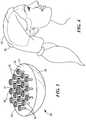
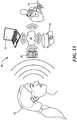
- FIG. 1is a top perspective view of a sensor assembly according to an embodiment of the invention
- FIG. 2is a bottom perspective view of the sensor assembly of FIG. 1 ;
- FIG. 3is a bottom perspective view of a further embodiment of a sensor assembly
- FIG. 4is a side view of a sensor assembly in use applied to a subject's scalp
- FIG. 5Ais a schematic front view of a headband supporting a sensor assembly
- FIG. 5Bis a schematic isometric view of the headband and sensor assembly of FIG. 5A ;
- FIG. 6is a schematic diagram of electronics in the sensor assembly
- FIGS. 7A-7Dare graphs illustrating the improvement in signal-to-noise ratio (SNR) of EEG and EFEG from an embodiment of a 19-pin sensor array compared to a traditional EEG sensor;
- FIG. 8is a schematic illustration of an image of brain activity generated from EFEG data obtained from a sensor assembly
- FIG. 9is a graph of a proportion of correct classifications and corresponding signal-to-noise ratio (SNR) from an experiment testing a 4 ⁇ 4 sensor array;
- FIG. 10is a graph of SNR as a function of sensor density
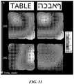
- FIG. 11illustrates an example from one subject of visually evokes responses averaged over epochs across an ultra-dense EEG array
- FIG. 12illustrates in the top panel, snapshots of dVEP variation across an ultra-dense EEG array for five subjects; in the middle panel, a time course of an electrode closest to a hotspot, and in the bottom panel, snapshots of dVEPs interpolated using only the corner electrodes;
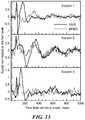
- FIG. 13are graphs of an EEG signal and an EFEG signal over time from an embodiment of a sensor array tested on three subjects;
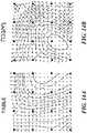
- FIGS. 14A and 14Bare maps of EFEG signals of electric fields from a local area of a brain obtained during testing of an embodiment of a sensor array;
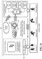
- FIG. 15is a schematic illustration of an embodiment of a sensor assembly in wireless communication with a network of devices
- FIG. 16is a schematic illustration of an embodiment of several sensor assemblies in a medical body area network
- FIG. 17is a graph of acceleration over time from a smartphone accelerometer showing a sudden fluctuation indicating a potential fall
- FIG. 18is a graph of rotation over time of a smartphone showing a sudden fluctuation indicating a potential fall
- FIG. 19is a graph comparing a fall detection technique of the present invention to three other fall detection apps, showing the number of false alarms and the number of missed detections;
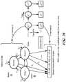
- FIG. 20is a schematic illustration of a Hidden Markov Model used to infer neurological states from sensor data.
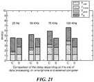
- FIG. 21is a graph comparing the time delay of the site of data processing on a smartphone to an external computer.
- the present sensor system and processare capable of electric field encephalography (EFEG) as well as EEG.
- the sensor systememploys a sensor assembly utilizing a plurality of sensors closely spaced in an array. For each sensor, the system can determine the electric potential (EEG), the electric field components (EFEG), and higher order derivatives of the potential, such as its surface Laplacian. From the measured electric field data, an estimate of the location of the electric field sources can be made and an image of brain activity can be generated.
- the systememploys a number, N, of sensors, each associated with an active independent amplifier.
- Na number of sensors, each associated with an active independent amplifier.
- SNRsignal-to-noise ratio
- the sensor systemincludes a sensor assembly 20 supporting a plurality of individual sensors 30 arranged in an array 32 .
- Each sensoris an electrode 34 having a suitable configuration for making good electrical contact with the scalp.
- each electrodeis in the form of an electrically conductive pin 35 .
- the end or tip of each pincan be, for example, convexly rounded ( FIG. 2 ), cup-shaped or concave, or waffle-shaped ( FIG. 3 ).
- the configuration of the tip or endcan depend on the hair type (for example, curly, straight, fine, thick) and amount (for example, heavy, thin, balding) of the subject.
- the electrodescan be pressed into contact with the scalp if desired, for example, with a spring mechanism.
- Suitable electrode materialsinclude silver, gold, copper, and alloys thereof.
- the electrodesare formed with a silver core and a Ag/Cl coating on the surface to prevent or minimize DC polarization at the scalp-electrode interface.
- Other electrode or electric field sensor configurationscan be used if desired.
- Other sensor configurationscan include electro-optical sensors such as photonic crystals made of lithium niobate.
- the sensor assembly 20includes a support plate 36 or other structure for mounting or supporting the electrodes 34 .
- the pins 35 of the electrodesextend through the support plate to protrude from a first side 37 .
- Electronic components 42 that interface with the electrodesare mounted on or supported by the other, second side of the support plate 36 . (See FIG. 1 .) Connections between the electrodes and the electronic components are made on the second side of the support plate.
- the sensor assemblyalso includes a housing or cover 38 to enclose the electronic components.
- the housingis sized to attach to an area of the scalp of a subject 40 with the protruding electrodes in electrical contact with the scalp. See FIG. 4 .
- the housing or covercan be grasped by a user when placing the sensor assembly on a subject's scalp.
- the sensor assemblyis sufficiently small such that several sensor assemblies can be attached to the subject's scalp if desired.
- the electrodes 34 supported by a sensor assembly 20can be arranged in any suitable array 32 , and any suitable number, N, of electrodes can be provided.
- the electrodescan be more closely spaced than the electrodes used in traditional EEG.
- Electrode densitycan be, for example, 0.3 cm ⁇ 2 , 1.0 cm ⁇ 2 , 4.0 cm ⁇ 2 , or greater. Lesser electrode densities can also be used, if desired, depending on the application.
- 19 electrodesare arranged in a hexagonal array ( FIGS. 2, 3 ) with an interspacing of 3 to 4 mm. The array is 2 cm in diameter at its widest dimension.
- the combined area of the 19 electrodes, when applied to a scalp surface,is a few square centimeters.
- 16 electrodesare arranged in a square 4 ⁇ 4 array.
- the electrode interspacingis 1 cm. It will be appreciated that the electrodes can be arranged in other patterns, such as circular, triangular, or the like, or in no regular pattern, and the term “array” can encompass all such patterns or no pattern.
- the sensor assembly 20 including the housing 38can be sufficiently miniaturized that it can be attached to a scalp relatively unobtrusively.
- the sensor assemblycan be formed with a lower profile than the profile of currently used EEG sensors.
- the sensor assemblycan be attached to the scalp in any suitable manner.
- the sensor assemblycan be attached with tape or an adhesive suitable for use on skin and hair.
- the sensor assemblycan be held in place with a device such as a headband or a headset.
- the sensor assemblycan be integrally formed with the headband or headset.
- the headband or headsetcan be adjustable to fit a variety of head sizes and shapes.
- the headband or headsetcan be configured to support more than one sensor assembly, such as 2, 3, 4, or more sensor assemblies. See, for example, FIGS.
- setup timecan be 5 minutes or less.
- reliable electrical contact with the scalpcan be made without the use of liquid or gel electrolytes, which can create electrical bridges and severely reduce the spatial resolution of dry electrode EEG.
- each electrode 34is electrically connected to an associated amplifier 44 . See FIG. 6 .
- the amplifieramplifies the potential difference between its associated electrode 34 and a reference electrode.
- the output of each amplifieris fed into an associated analog to digital converter (ADC) 46 , which in turn transmits the digital signal representative of the potential difference to a microcontroller 50 for further data processing, described further below.
- ADCanalog to digital converter
- one of the electrodes in the sensor arrayis a reference electrode.
- the central electrodeis selected as the reference electrode 37 to simplify the geometrical considerations, but any other electrode could be selected instead.
- the potentials on the remaining N ⁇ 1 electrodesare measured with reference to the reference electrode by the associated amplifiers. In this way, local electric field components can be estimated via local gradients of the potential.
- the reference electrodecan be a traditional EEG electrode, for example, attached at another location on the scalp or to the earlobe, or it can be an electrode on a different sensor assembly placed at a different location on the scalp.
- the sensor assembly described hereincan be used simultaneously in EEG and EFEG regimes. Both EEG and EFEG can be sampled concurrently by dynamically switching each amplifier's reference between the remote reference electrode for EEG mode and the local reference electrode for EFEG mode, for example, with a multiplexer at the inputs to the amplifiers.
- the EEG regimeis most useful when global activity of the brain is of interest, such as alpha rhythm.
- the EFEG and Laplacian regimesare most useful when estimating local brain activity in the vicinity of the sensor assembly.
- the Laplacianis the curvature of the potential proportional to the skull-scalp current density.
- Scalp electric field patternsare more focused than the corresponding EEG patterns, and, unlike EEG, EFEG is free from the ambiguity of choosing the potential reference.
- Laplacian patternsare even more focused, but the Laplacian measure, being the second derivative of the potential, is also more affected by the measurement noise than EFEG.
- one electrodefor example, the central electrode
- the central electrodeis used as a local potential reference with respect to which potentials on the remaining N ⁇ 1 electrodes, the active electrodes, are measured by the associated amplifiers.
- local electric field componentscan be estimated via local gradients of the potential.
- F istands for the potential signal from the i-th electrode
- ⁇ F istands for the (amplified) potential difference between the i-th electrode sensor and the reference electrode
- Nis the number of electrodes
- x istands for the x-coordinate of the electrode with respect to the center of the array.
- An analogous formulagives the y-component of the field. A radial component can be similarly measured if desired, but is generally not necessary, as the tangential components are dominant. If a different electrode is the reference electrode, the equations can be appropriately weighted to reflect the geometry of the location of the reference electrode.
- the amplified EEG potentialsare averaged by the sensor assembly:
- F istands for the potential signal from the i-th electrode in reference to the first electrode
- Nis the number of electrodes.
- the calculationsimplement optimal probability summation, in which each electrode's signal is weighted by the inverse of its noise variance, thus achieving the highest possible SNR.
- the resulting SNR increase compared to a single EFEG channel implemented as a bipolar EEG pairis given by ⁇ (N ⁇ 3) for EFEG and ⁇ (N ⁇ 1) for the Laplacian.
- the expected increase in SNR compared to a single amplifier channelis given by ⁇ N.
- the SNR⁇ 19 ⁇ 4.559.
- the sensor systemcan employ additional techniques to improve the SNR.
- Active amplifiersgreatly improve the signal quality by reducing the capacitive coupling between an output cable and the possible sources of interference.
- the amplifiersneed to be as close to the sensors as possible.
- the first stage amplificationis done using active amplifiers 44 that are mounted close to the sensors, within the sensor assembly 20 .
- the electrodes 34are fixed within through holes in the support plate 36 and are connected very closely to their associated amplifiers 44 , which are disposed on a chip that is also supported on the second side of the support plate. See FIG. 1 .
- one or more ADS1298 or ADS1299 chips 48commercially available from Texas Instruments can be used. These chips are multichannel and employ simultaneous sampling, 24-bit, delta-sigma analog-to-digital converters (ADCs) with built-in programmable gain amplifiers (PGAs), internal reference, and an onboard oscillator. Each chip can provide amplification for 8 independent channels. For example, for an embodiment of the sensor assembly employing 19 electrodes, three of these chips are used, which gives 24 available independent channels. The outputs from the electrodes connect to one of the eight inputs of each of the chips. It will be appreciates that future generations of similar chips can also be used.
- ADCsanalog-to-digital converters
- PGAsprogrammable gain amplifiers
- the ADS1298 or 1299can sample data at 24 bits with an ADC rate of 3 bytes per sample per channel. This sampling resolution and rate are adjustable to get the highest SNR and adequate data quality.
- a typical point sampling rateis 1 kHz, and this gives a data sampling rate of 3 kB/s per channel. For 700 channels, this gives a data rate of 2.1 MB/s. It will be appreciated that higher rates may be achievable with other chips now or in the future.
- Each chip 48outputs the data in a digital form through its serial peripheral interface (SPI) channel 49 (channels 1 , 2 , and 3 ).
- SPIserial peripheral interface
- the driven right leg (DRL) of each chipis merged into a single DRL output, and the analog differential negative inputs end up as the common reference (V ref ) input to the microprocessor. All the input signals are sampled in digital form and the information is processed in the microcontroller 50 .
- the microcontroller 50can also be supported by the support plate 36 of the sensor assembly 20 . It receives the output signals from the ADCs for continuous monitoring and additional signal processing.
- the microcontrollercontains a microprocessor, input and output control, and memory (RAM, ROM, etc.) with instructions to perform signal pre-processing resulting in EFEG time-series.
- the sensor assemblycan also include a power supply, such as a battery, for example, a lithium polymer battery. Power consumption is relatively low, generally less than 200 mW.
- the microcontroller and other chipscan be stacked if desired to fit within a small footprint within the housing 38 of the sensor assembly 20 .
- the on-board microprocessoris used to compute the electric field components from the individual electrode voltages, as described above, and also can be used for more involved computations in-situ, for example, to reduce data redundancy, for example, to mitigate effects of noise through additional signal processing, and to compute the signal field strengths, before the data is communicated to a transceiver 52 for transmission to another device. If exact timing or real-time data is required, FPGAs can be used.
- the bias drive circuitryprovides a path for the current (common-mode signal) from the reference and into the differential inputs of the amplifiers 44 to actively cancel electromagnetic interference (EMI) and improve the common-mode rejection.
- the microprocessoractively monitors each of the programmable gain amplifiers. If it senses any of the electrodes has loosened (by comparing the signal amplitude with the dynamic range), then it can dynamically open the switch of the associated amplifier and eliminate it from the closed-loop gain of the bias drive signal. This can improve the common-mode rejection of the entire sensor assembly.
- FIGS. 7A-7Dillustrate SNR improvements for EEG and EFEG signals obtained in a simulation, where SNR for a single EEG channel was set to 1.
- the sensor arrayemployed a 19-pin geometry as shown in FIG. 2 and a simulated electric field of a constant magnitude of 1 ⁇ V/cm rotating at 4 Hz.
- FIG. 7Bindicates a ⁇ 19 improvement in the SNR of EEG potential detected with the 19-pin sensor array over a traditional EEG in FIG. 7B .
- FIG. 7Dindicates a 4-fold improvement in SNR for the associated electric field measurements.
- FIG. 8is a schematic illustration of an image of brain activity generated using a software suite known as Harmony. See Petrov, Y., Harmony: EEG/MEG Linear Inverse Source Reconstruction in the Anatomical Basis of Spherical Harmonics. PLOS ONE, October 2012, Vol. 7, Issue 10, e44439.
- An embodiment of a sensor assemblywas tested to determine if EFEG provides additional information on brain activity compared to conventional and high-density EEG, and to determine if the closer electrode spacing, that is, an ultra-dense electrode density, within the sensor assembly is capable of providing additional EEG information compared to the sensor spacing or electrode density of traditional and high-density EEG.
- a sensor array with an ultra-dense array of electrodeswas used in which a square 4 ⁇ 4 grid of small diameter electrodes had an inter-electrode separation of 1 cm, or a density of 1.0 cm ⁇ 2 .
- the electrode density of several 128-sensor EEG nets from Electrical Geodesics Inc.was estimated as 0.167 cm ⁇ 2 .
- the electrode density of EEG nets with 64 sensorswas estimated to be 0.084 cm ⁇ 2 ; and the electrode density of a net with 256 sensors, currently the densest EEG nets commercially available, was estimated to be 0.269 cm ⁇ 2 .
- the approachused a signal classification paradigm in which a classification algorithm was used to carry out binary classification of individual trials based on their EEG data. It was hypothesized that the amount of functional information I captured by the array is a monotonically increasing function of the algorithm's classification accuracy p c .
- the advantage of this approachis that (i) it gives an estimate of functional brain information compared to mere spatial variation of EEG, and (ii) given a “hotspot” of the functional information relevant to the classification task on the scalp, it is sufficient to estimate I at this location as a function of sensor density, I(d), to obtain a reliable estimate of the full-scalp I(n).
- a common “informative” locationwas chosen in the parieto-occipital scalp region, approximately 6 cm above and left of the inion.
- the 4 ⁇ 4 ultra-dense sensor arraywas applied to this location for all subjects.
- Recorded visually evoked potential (VEP) epochswere separated into two sets, English and Hebrew, based on which stimulus was presented in a given epoch. Part of the data was used for training a classification algorithm, while the remaining data were used for testing the performance of the trained algorithm, using the Na ⁇ ve Bayes approach.
- VEPvisually evoked potential
- the percentage of correctly classified trials (p c )varied among subjects from 52% to 78%.
- SNR and p c for each subjectare plotted along the y-axes in FIG. 9 ; error bars show one standard deviation. When all 16 electrodes (full 4 ⁇ 4 array) were used, the SNR was 0.47 ⁇ 0.02 on average.
- SNR for two intermediate sensor densitieswas estimated by interpolating the 4 ⁇ 4 array data to square arrays with 5 and 9 electrodes, thus emulating full-scalp EEG arrays of 168 and 336 sensors respectively.
- SNR as a function of the sensor densitygrew approximately logarithmically ( FIG. 10 ).
- VEPs for a representative subjectare shown in FIG. 11 .
- Datawere averaged over stimulation epochs, interpolated between electrodes in the 4 ⁇ 4 array, shown here by a varying grayscale, although usually represented by color maps. The electrode locations are marked by black dots.
- Responses to English and Hebrew stimuliare shown on the left and right respectively. Snapshots for the two time points, as indicated by the time arrow, demonstrate functional variation of the responses between the two conditions: while evoked responses were alike at 200 ms from the stimulus onset, they became quite different 80 ms later.
- the dVEP time course of the electrode with the largest observed dVEPis plotted below each snapshot. The dot above each plot indicates when the corresponding snapshot was taken.
- the observed dVEP variations across the ultra-dense EEG arrayare highly significant and formed local hotspots: the potential variations between English and Hebrew stimuli were as high as 2 ⁇ V/cm for some subjects. Time courses of the hotspots have well-defined peaks. This indicates that the hotspots reflect evoked brain responses rather than measurement-related noise.
- the hotspotsare made particularly conspicuous by their absence in dVEPs interpolated using corner electrodes only. This is shown in the bottom panel of FIG. 12 . Note also that the shown data reflects local variation of VEP measured with respect to the array's average and thus may look different from conventional VEPs recorded using global reference.
- the observed classification SNR improvement of ultra dense EEG on high density EEGmay result from: (i) an increased number of independent signals, as reflected by the dVEP hotspots in FIG. 12 , or (ii) decreased noise due to noise averaging among nearby ultra dense EEG electrodes.
- the classification analysiswas repeated while limiting the number of classifiers to the single most informative electrode. This precluded any noise averaging between nearby electrodes.
- the average SNR for the full 4 ⁇ 4 arraydropped from 0.47 ⁇ 0.02 to 0.25 ⁇ 0.02, but the 4-corner SNR decreased proportionally from 0.27 ⁇ 0.02 to 0.15 ⁇ 0.02. This demonstrates that noise averaging cannot explain the observed improvement in classification accuracy.
- FIG. 13illustrates the measured EFEG and EEG at one location within the brain for three of the subjects, indicating that EFEG provides information in addition to that provided by EEG.
- the spatial variation of the potentials and the fieldsare shown in FIG. 14A for an English stimulus and in FIG. 14B for a Hebrew stimulus.
- the data for a sensor assembly 20can be transmitted to a peripheral device for further analysis.
- Transmission of signals from the sensor assemblycan be wired or wireless, for example, via connection standards such as Bluetooth, Zigbee, WiFi, 802.15.4, WLAN, RFID and other wireless standards.
- connection standardssuch as Bluetooth, Zigbee, WiFi, 802.15.4, WLAN, RFID and other wireless standards.
- AC noisecan be reduced further, because a length of cable is eliminated.
- the output datacan be saved locally on a flash drive continuously and can be transmitted to a host system or cloud storage wirelessly in real time with certain latency.
- a sensor system 80in which one or more the sensor assemblies can communicate with a device 85 such as a smartphone, tablet computer, laptop computer, or other device.
- the device 85can in turn transmit the data to another host system, for example, via the internet 90 .
- the sensor assemblycan transmit data wirelessly to the subject's smartphone, which can in turn transmit the data to another external computer 82 , a processor device 84 employed by a physician, clinician, or researcher, or another networked facility 86 located remotely from the subject.
- the subjectcan be continuously monitored in a location, such as his or her home, that is remote from a hospital or other medical facility or a laboratory.
- an epilepsy patientcan be continuously monitored for signals indicative of an epileptic seizure while maintaining a normal routine at home, rather than being admitted to a hospital for such continuous monitoring. Messages from the clinician can be transmitted back to the subject as necessary.
- the data from the sensor system 80can be used by, for example, a trained researcher conducting investigations into brain electromagnetic activity or a clinician diagnosing neurological conditions.
- the systemcan be used to diagnose and treat animals, including mammals and, in one embodiment, human subjects.
- the systemcan be used for functional brain imaging at high temporal and spatial resolution, for pattern recognition and cognition, or for comparing the brain activity of a subject to the brain activity of a normal subject or to a database of the brain activity of many subjects.
- the systemcan be used to investigate neural correlates of vision and speech, aging, sleep, or diseases such as epilepsy, Alzheimer's disease, Parkinson's disease, amyotrophic lateral sclerosis (ALS), stroke, autism, depression, and traumatic brain injury.
- ALSamyotrophic lateral sclerosis
- the datacan be analyzed for source localization for epilepsy or for detecting correlations between EFEG and EEG patterns with seizures or silent events.
- the systemcan be used to detect correlations between gait and attention in movement disorders during the aging process and/or in Parkinson's disease.
- the systemcan be used during movement rehabilitation of stroke patients, for patient-driven neurorehabilitation, mobile brain/body imaging, gait research and gait rehabilitation and neuroergonomics.
- the systemcan be used for investigating or utilizing human-machine and brain-computer interfaces.
- brain-computer interfacesrequire an active stimulus, often in the form of a flickering pattern, which the user is expected to focus on for extended durations of time.
- the sensor arrayin contrast, directly picks up and transmits in real time the brain activities of the subject in normal settings, without the need for specialized equipment.
- signals from a sensor arraycan be transmitted to a host processor and used to control an external device, for example, to turn a device on or off, move a cursor, control the volume of an audio output, control a prosthetic device, control a wheel chair, control a speech synthesizer, make a phone call, or provide a sound or vibration to awaken a sleepy driver.
- the host processorcan make a comparison of the transmitted signals representative of an emotion or an intentional thought with a database, look-up table, or brain map.
- a training regimencan be performed by which a user can learn use of brain activity to control a device.
- a sensor systemcan include one or several sensor assemblies 120 worn by a subject 140 to gather brain activity data. See FIG. 16 .
- Other sensors that currently exist within a smartphone 160such as a GPS device 162 , an accelerometer 164 , a gyroscope 166 , and a magnetometer 168 , can be used to provide context data when the smartphone is worn or carried by the subject. (It will be appreciated that such sensors can be provided on any other form of wearable device in addition to a smartphone and references to a smartphone herein can include any such other device.)
- Other devices 180that use cameras and microphones to capture movement and speech of a subject can be used to provide context data as well.
- MBANmedical body area network 190
- Data from the brain activity sensor assembliescan be synchronized with data from the other sensors and devices that provide context, so that the subject's brain activity can be associated with the activity that the subject is performing.
- factors that trigger a particular neurological statesuch as mood, anxiety, stress, cognitive functioning, or sleep, may be identified, which may help in recommending treatment.
- FIGS. 17 and 18show the acceleration, linear acceleration, angular velocity and orientation data collected by a smartphone when a person is walking normally but suddenly falls down.
- the accelerations in all three axesare combined to find the total acceleration:
- ( a 2 x +a 2 y +a 2 z ) 1/2
- the individual tracesare shown in FIG. 17 .
- the angular velocitycan be collected using the hardware-based tri-axial gyroscope.
- a smartphone's coordinate systemis defined relative to the phone and the axes remain static throughout. That is, the axes are not appropriately rotated when the smartphone's orientation changes.
- the geometric mean valueis more useful and can be calculated from the velocities in three orthogonal directions:
- ( w 2 x +w 2 y +w 2 z ) 1/2
- the tracesare shown in FIG. 18 .
- the orientation of the phoneis determined by the azimuth, the pitch (the angle around one axis, e.g., the x-axis) and the roll (the angle around another axis, e.g., the z-axis).
- a fall detection techniquecompares the total acceleration against an empirically measured threshold obtained from multiple subjects and checks if the rotation sensor registers a simultaneous change of more than 90°. Coordinating the fall data with the subject's electromagnetic brain activity may lead to an evaluation of the cause of the fall and possibly a diagnosis and course of treatment.
- the present fall detection techniquehas been found to result in lower false alarms and missed detection errors compared to other commercially available apps, as shown in FIGS. 19A and 19B .
- Nos. 1 , 2 , and 3represent commercially available smartphone fall detection apps.
- No. 4represents the present fall detection technique described above.
- the data analysiscan occur on the smartphone, or the smart phone can transmit the data to another computer for analysis.
- the detected contextis the action of the user falling down, it may indicate an urgent notification event.
- the data collection from the sensor array and the event of the fall, when taken togethermay point to a possibility of a stroke.
- the dataare immediately transmitted by the smartphone to alert necessary caregivers.
- the systemcan include a database of sensor readings that are indicative of particular activities, such as watching TV, sitting, eating, walking, or exercising.
- simple daily activitiessuch as watching TV, may introduce temporary changes in the stress level and the mental state of a subject, depending on the TV program's content.
- the systemcan include a map of the living space or other environment of the subject with coordinates of elements, such as facilities and equipment, for example, the locations of a TV, washroom, exercise machine, dining table, and the like.
- the assisted GPS (AGPS) capability of the smartphonecan be used to determine the location of the subject within a room or within a facility.
- the accelerometercan be used to detect if the subject is undergoing continuous motion, suggesting a vigorous physical activity.
- the orientation of the smartphone and hence, the subject, with respect to the Earth's magnetic axisis determined using the smartphone's magnetometer.
- the point location of the AGPS as well as the orientation along the line of sight to the TVcan indicate with a high probability that the subject is watching TV.
- a device that captures movement and speech of a subjectsuch as the KINECT®, available from Microsoft and developed initially for the gaming field, provides the capability of producing a digital representation of skeleton-figures of a subject without the privacy invasion that accompanies a visual confirmation from continuous monitoring by another person.
- These skeleton figuresare expressed as a graph of vertices and edges that correspond to the joints and limbs of the subject under study.
- the devicealso returns information on depth estimation, which provides additional location information within the room. Using such a device, instances can be captured in which the subject does not physically change location, hence recording zero variations by the smartphone accelerometer, but still engages in limited motion that impacts the neurological data.
- the movement of the subject's lower jawcan introduce noise into the sensed data by the sensor assembly for monitoring brain activity, which may result in a sudden spike.
- the skeleton figure datacan be used to check if the loci of the vertex and edge movements are regular, perhaps corresponding to that of a moving arm during eating.
- the movement capture devicecan be activated if the sensors on the smartphone indicate a potential fall by the subject.
- a database of patterns engaged in by the subjectcan be provided to establish a comprehensive context-aware framework.
- the smartphonecan be placed in a master role to poll slave nodes, such as one or more brain activity sensor assemblies and other external devices, such as movement and sound capture devices.
- the smartphonecan timestamp and aggregate the data from all the sources, including the sensors on board the smartphone itself.
- the smartphonecan continuously monitor the sensor data and if deviations from a known or predicted pattern are detected, it can increase the duty cycle for the affected sensors.
- the smartphonecan send the data, for example, in a compressed format, to a host processor or to a cloud computing facility for subsequent data analysis.
- the smartphonecan transmit the data to an external computer, such as a laptop computer, for data analysis.
- the data processing and analysiscan occur on the smartphone itself. As one example, if the data analysis on the smartphone suggests that the subject may have fallen, the smartphone can activate a movement capture device and/or transmit an alert to other personnel for a visual check.
- FIG. 21compares the delay for these two approaches at different data sampling rates of 25 Hz, 50 Hz, 75 Hz, and 100 Hz.
- the computer-based approachis indicated by “C”
- the smartphone-based approachis indicated by “S.”
- the total delayis composed of the times it takes to (i) analyze the data (T proc ), (ii) connect to the TCP server running on the computer (T conn ), (iii) send the data (T trans ), and (iv) trigger the KINECT® device (T K ).
- T procthe data
- T connthe computer
- T connthe computer
- T transsend the data
- T transthe data
- T KK
- Smartphonesnot only serve as personal communication devices and a convenient way to access to the Internet, but also as powerful processing platforms.
- the latest commercially available modelsprovide computational capability in the range of 1.5 GHz dual-core processors and 1-2 GB of RAM, depending on the handset maker.
- the smartphonecan act as a central gateway between the sensor assembly or assemblies and a computing cloud, capable of relaying data and inferences back and forth, as well as selecting the computational resource appropriate for the processing tasks.
- the Amazon Elastic Compute Cloud(Amazon EC2) can be used.
- the elastic nature of this serviceallows the system to instantly scale to meet spikes in traffic or demand. Parameters that are used in this decision framework are the energy cost of processing, the overhead of transmitting data over the wireless channel in terms of bandwidth use, and the processing latency to complete the task.
- the phoneuses less battery power when collecting data from the sensors every 40 ms (25 Hz), than when polling the sensors every 10 ms (100 Hz).
- the smartphonecan continuously track and predict the sensor data from the sensor array(s), and when marked deviations are observed, increase the duty cycles of those particular sensors.
- the smartphone processorcan perform electric field encephalography (EFEG) data pre-processing, artifact removal, raw and averaged data visualization, including causality, classification, and source reconstruction analyses.
- EFEGelectric field encephalography
- the smartphonecan timestamp and synchronize the data from the multiple sensor streams, and undertake a first round of data aggregation and compression. It can also undertake cross-correlation among the sensor data to identify matches of neural activity spikes with the observed sensor data, such as changes in accelerometer or orientation readings.
- time series analysis and autocorrelation studiescan be performed on massive volumes of historical data that are collected by the smartphone and stored in the cloud.
- One such study that requires large computational capability of the cloud processingis a time series decomposition where the temporal data for each of the sensors in the neural network for a given activity is broken down into long-term trends, sudden spikes, and cyclical components. This can help in identifying how neural activity changes with age, and its fluctuations over the short and long-term time scales.
- HMMsHidden Markov Models
- a HMMincludes a Markov chain whose states are hidden, as opposed to observable variables that are resultants of hidden states.
- the neurological states ⁇ normal, S 1 , S 2 ⁇form a Markov chain as shown in FIG. 20 .
- the range of the sensor measurementscan be defined as the boundary values ⁇ [O min 1 , O max 1 ], [O min 2 , O max 2 ], . . . , [O min N , O max N ] ⁇ for the N classes of observations.
- the HMMallows the probabilistic mapping of a given observation to each of the neurological states, one of which is responsible for causing these observations to occur.
- Simple daily activitiessuch as watching TV, may introduce temporary changes in the stress level and the mental state of the patient depending on the program content, and it can be helpful to identify the context of sudden changes in the neural signal, if any, to distinguish more serious conditions, such as stroke.
- the smartphonecan request an estimation of the living space of the patient with coordinates of key facilities and equipment, such as TV, washroom, exercise machine, dining table, among others, for example, through a drop-down menu.
- the assisted GPS capability (AGPS) of the smartphonehelps in localization of the patient within a room in the facility of interest.
- the accelerometercan detect if the subject is undergoing continuous motion, suggesting a vigorous physical activity.
- the orientation of the phone (and hence, the subject) with respect to the Earth's magnetic axisis checked using the magnetometer.
- the point location of the AGPS as well as the orientation along the line of sight to the TVcan indicate with high probability that the patient is watching TV.
- the HMM output in this scenariois weighted down as a non-risk stage, given that sudden changes in neurological states are likely due to the visual sensory inputs.
- the sensor systememploys Bluetooth technology as the underlying channel access method, which is a low-energy standard, suitable for wireless connectivity over short distances (typically ⁇ 10 m).
- Bluetoothaccommodates 7 active connections (slave devices) for a single master device, and additional devices can be placed in a low-power parked mode.
- the masterfor example, the smartphone, is responsible for polling the slaves nodes, aggregating the data, and sending a compressed set of readings to the Internet cloud for comprehensive processing.
- alternative communication technologiessuch as using radio, can be employed.
- the sensor assemblycan be configured to transmit signals in the medical body area network transmission band of 2360 to 2400 MHz recently specified by the Federal Communications Commission. Because this frequency band is heavily used, the system can employ a statistical activity model to identify the best frequency bands for transmission. These activity models are also used to formulate channel access schemes with interference avoidance with higher priority users, and ensure that data reporting requirements of the neurological signals are met with acceptable latency overhead.
- the systemcan use a channel hopping pattern for avoiding portions of the frequency within the MBAN band that exhibit high levels of interference. Moreover, whenever there is a statistically high possibility of higher priority users within the MBAN band, a sensor array can pause an ongoing transmission, and lower the probability of selecting that subchannel in the next round of its hopping sequence. For other lower priority/peer-level users, however, the system can continue to include that particular subchannel in its hopping sequence, thereby allowing more numbers of distinct hopping sequences within the system's neural network.
- the core operational techniqueis first identifying a distribution function that gives the probability of spectrum being available at a given frequency f and for time duration t, which evolves with time, weighting recent measurements higher than those obtained earlier for the same external conditions. This distribution is used for selecting the set of channels for the hopping sequence.
- the present systeminvolves the dynamic leveraging of channel selection under different priority transmitters in the MBAN band.
- WMTSwireless medical telemetry service
- DTVdigital television
- iilower-L band
- iiiupper-L band
- military and governmental agencieshave a priority access in the lower-L band spectrum with a number of operational radars.
- the upper-L band and the lower-L bandsare used by non-medical telemetry companies on a priority access and equal-access basis, respectively.
- the system and process for measuring electromagnetic activity of the brain as described hereincan provide a number of advantages.
- the EFEG measurement modalityresults in high resolution local measurements, while also providing for globally referenced EEG measurements.
- the sensor systemprovides significant improvement in the signal-to-noise ratio.
- the sensor assembly of the sensor systemis unobtrusive, has a small footprint, is self-contained, can be operated wireless, and locally referenced.
- the sensor assemblycan be quickly placed on a subject's head and similarly it can be quickly removed.
- the sensor arrayworks with a variety of hair types.
- the electrodes of the sensor assemblycan be used dry or with an electrolyte gel.
- the sensor systemcan be used for continuous monitoring, for example, 24/7, of a subject's brain activity to provide low-profile, real-time monitoring of brain activity.
- the sensor systemcan communicate with a variety of processors or other devices, such as a smartphone, laptop computer, or tablet computer. Communication can be via a wired connection or a wireless connection.
- the sensor systemincludes a measurement system including hardware and algorithms for data transfer, data preprocessing and analysis.
- the present systemis applicable in a variety of fields.
- the systemcan be used for functional brain imaging at high temporal and spatial resolution, for pattern recognition and cognition.
- the systemcan be used for conducting brain research, for example, to investigate neural correlates of vision and speech, aging, sleep, diseases such as epilepsy, Alzheimer's disease, Parkinson's disease, ALS, stroke, autism, depression, and traumatic brain injury.
- the systemcan be used for investigating human-machine and brain-computer interfaces.
- the systemcan include one or several sensor assemblies worn by a subject to gather brain activity data along with other sensors, such as those found in a smartphone or other devices, such as an image and/or sound capture device.
- the systemcan be used as a neural network and can be used to provide context data for a subject.
- the systemcan be integrated into a medical body area network for the subject.
- references to a smartphone hereininclude other devices that may be worn or carried by the subject.
Landscapes
- Health & Medical Sciences (AREA)
- Life Sciences & Earth Sciences (AREA)
- Engineering & Computer Science (AREA)
- Veterinary Medicine (AREA)
- Biophysics (AREA)
- Biomedical Technology (AREA)
- Heart & Thoracic Surgery (AREA)
- Medical Informatics (AREA)
- Molecular Biology (AREA)
- Surgery (AREA)
- Animal Behavior & Ethology (AREA)
- General Health & Medical Sciences (AREA)
- Public Health (AREA)
- Physics & Mathematics (AREA)
- Pathology (AREA)
- Neurology (AREA)
- Neurosurgery (AREA)
- Physiology (AREA)
- Developmental Disabilities (AREA)
- Multimedia (AREA)
- Psychiatry (AREA)
- Hospice & Palliative Care (AREA)
- Child & Adolescent Psychology (AREA)
- Psychology (AREA)
- Measurement And Recording Of Electrical Phenomena And Electrical Characteristics Of The Living Body (AREA)
- Computer Networks & Wireless Communication (AREA)
- Artificial Intelligence (AREA)
- Computer Vision & Pattern Recognition (AREA)
- Signal Processing (AREA)
Abstract
Description
where Fistands for the potential signal from the i-th electrode and ΔFistands for the (amplified) potential difference between the i-th electrode sensor and the reference electrode. N is the number of electrodes and xistands for the x-coordinate of the electrode with respect to the center of the array. An analogous formula gives the y-component of the field. A radial component can be similarly measured if desired, but is generally not necessary, as the tangential components are dominant. If a different electrode is the reference electrode, the equations can be appropriately weighted to reflect the geometry of the location of the reference electrode.
where Fistands for the potential signal from the i-th electrode in reference to the first electrode, and N is the number of electrodes.
where ristands for the distance from the electrode to the center of the array.
SNR=0.476+0.086 log(d),
where d is the density of sensors: 0.11, 0.22, 0.44, and 1 cm−2for 4, 5, 9, and 16-electrode ultra-dense EEG array configurations, respectively.
|AT|=(a2x+a2y+a2z)1/2
The individual traces are shown in
|wT|=(w2x+w2y+w2z)1/2
The traces are shown in
Claims (11)
Priority Applications (1)
| Application Number | Priority Date | Filing Date | Title |
|---|---|---|---|
| US14/896,511US10912480B2 (en) | 2013-06-21 | 2014-06-20 | Sensor system and process for measuring electric activity of the brain, including electric field encephalography |
Applications Claiming Priority (3)
| Application Number | Priority Date | Filing Date | Title |
|---|---|---|---|
| US201361837692P | 2013-06-21 | 2013-06-21 | |
| US14/896,511US10912480B2 (en) | 2013-06-21 | 2014-06-20 | Sensor system and process for measuring electric activity of the brain, including electric field encephalography |
| PCT/US2014/043425WO2014205356A2 (en) | 2013-06-21 | 2014-06-20 | Sensor system and process for measuring electric activity of the brain, including electric field encephalography |
Publications (2)
| Publication Number | Publication Date |
|---|---|
| US20160120432A1 US20160120432A1 (en) | 2016-05-05 |
| US10912480B2true US10912480B2 (en) | 2021-02-09 |
Family
ID=52105536
Family Applications (1)
| Application Number | Title | Priority Date | Filing Date |
|---|---|---|---|
| US14/896,511Active2036-08-26US10912480B2 (en) | 2013-06-21 | 2014-06-20 | Sensor system and process for measuring electric activity of the brain, including electric field encephalography |
Country Status (4)
| Country | Link |
|---|---|
| US (1) | US10912480B2 (en) |
| EP (1) | EP3010408B1 (en) |
| JP (1) | JP6503347B2 (en) |
| WO (1) | WO2014205356A2 (en) |
Cited By (5)
| Publication number | Priority date | Publication date | Assignee | Title |
|---|---|---|---|---|
| US11445960B2 (en)* | 2019-10-09 | 2022-09-20 | Trustees Of Boston University | Electrography system employing layered electrodes for improved spatial resolution |
| US11832946B2 (en) | 2021-11-17 | 2023-12-05 | Toyota Motor Engineering & Manufacturing North America, Inc. | Systems and methods for producing stimuli in a visual interface |
| US12093519B2 (en) | 2021-11-17 | 2024-09-17 | Toyota Motor Engineering & Manufacturing North America, Inc. | Systems and methods for producing stimuli in a visual interface using modulation |
| US12178580B2 (en) | 2019-12-23 | 2024-12-31 | Alimetry Limited | Electrode patch and connection system |
| US12354279B2 (en) | 2021-06-02 | 2025-07-08 | Zimmer Us, Inc. | Movement tracking |
Families Citing this family (82)
| Publication number | Priority date | Publication date | Assignee | Title |
|---|---|---|---|---|
| EP2661307A4 (en) | 2011-01-03 | 2014-08-06 | Univ California | HIGH DENSITY EPIDURAL STIMULATION TO FACILITATE LOCOMOTION, POSTURE, VOLUNTARY MOVEMENT AND RECOVERY OF SEXUAL, VASOMOTOR AND COGNITIVE AUTONOMY FUNCTION AFTER NEUROLOGICAL INJURY |
| EP2776120B1 (en) | 2011-11-11 | 2020-09-09 | Neuroenabling Technologies, Inc. | Non invasive neuromodulation device for enabling recovery of motor, sensory, autonomic, sexual, vasomotor and cognitive function |
| JP5951300B2 (en)* | 2012-03-19 | 2016-07-13 | 株式会社東芝 | Service control apparatus, service control method, and service control program |
| BR112015017042B1 (en) | 2013-01-21 | 2022-03-03 | Cala Health, Inc | Device to treat tremor |
| WO2014144785A1 (en) | 2013-03-15 | 2014-09-18 | The Regents Of The University Of California | Multi-site transcutaneous electrical stimulation of the spinal cord for facilitation of locomotion |
| US10137299B2 (en) | 2013-09-27 | 2018-11-27 | The Regents Of The University Of California | Engaging the cervical spinal cord circuitry to re-enable volitional control of hand function in tetraplegic subjects |
| CA2949843A1 (en) | 2014-06-02 | 2015-12-10 | Cala Health, Inc. | Systems and methods for peripheral nerve stimulation to treat tremor |
| US11234628B2 (en)* | 2014-11-25 | 2022-02-01 | Scienceplusplease, Llc | Non-invasive systems and methods to detect cortical spreading depression for the detection and assessment of brain injury and concussion |
| US9979088B2 (en) | 2015-02-02 | 2018-05-22 | The Charles Stark Draper Laboratory, Inc. | Mechanical antenna |
| CN104799853A (en)* | 2015-04-09 | 2015-07-29 | 中国科学院半导体研究所 | Tough claw type dry electrode used for recording electroencephalogram and preparation method |
| CN113724471B (en)* | 2015-04-30 | 2023-12-08 | 霍尼韦尔国际公司 | System for integrating multisensor data to predict fall risk |
| EP4342516A3 (en) | 2015-06-10 | 2024-07-10 | Cala Health, Inc. | Systems and methods for peripheral nerve stimulation to treat tremor with detachable therapy and monitoring units |
| WO2017053847A1 (en) | 2015-09-23 | 2017-03-30 | Cala Health, Inc. | Systems and methods for peripheral nerve stimulation in the finger or hand to treat hand tremors |
| CN105118236B (en)* | 2015-09-25 | 2018-08-28 | 广东乐源数字技术有限公司 | Paralysis falls to monitor and preventing mean and its processing method |
| EP3347725A2 (en) | 2015-10-06 | 2018-07-18 | The Charles Stark Draper Laboratory, Inc. | Electric field detector system |
| WO2017105594A2 (en) | 2015-10-06 | 2017-06-22 | The Charles Stark Draper Laboratory, Inc. | Magnetic field detector system |
| EP3361978B1 (en) | 2015-10-16 | 2025-07-02 | Dalhousie University | Systems for monitoring patient motion via capacitive position sensing |
| US10018686B1 (en) | 2015-10-21 | 2018-07-10 | The Charles Stark Draper Laboratory, Inc. | Ultra-low noise sensor for magnetic fields |
| EP3184043A1 (en)* | 2015-12-22 | 2017-06-28 | IMEC vzw | Sensor, system and holder arrangement for biosignal activity measurement |
| CA3011993C (en) | 2016-01-21 | 2024-05-14 | Cala Health, Inc. | Systems, methods and devices for peripheral neuromodulation for treating diseases related to overactive bladder |
| US11504038B2 (en) | 2016-02-12 | 2022-11-22 | Newton Howard | Early detection of neurodegenerative disease |
| US11957897B2 (en) | 2016-04-22 | 2024-04-16 | Newton Howard | Biological co-processor (BCP) |
| US10929767B2 (en)* | 2016-05-25 | 2021-02-23 | International Business Machines Corporation | Method for complex events detection using hidden markov models |
| US11850420B2 (en)* | 2016-09-19 | 2023-12-26 | Nyx Technologies Ltd. | Multifunctional closed loop neuro feedback stimulating device and methods thereof |
| US10531805B2 (en)* | 2016-09-30 | 2020-01-14 | The Charles Stark Draper Laboratory, Inc. | Biophysical sensing systems and methods using non-contact electric field detectors |
| WO2018085598A1 (en) | 2016-11-02 | 2018-05-11 | Northeastern University | Portable brain and vision diagnostic and therapeutic system |
| ES2976489T3 (en) | 2016-12-29 | 2024-08-02 | Elliot Steven Finkelstein | A portable system for monitoring brain trauma |
| US11235154B2 (en) | 2017-02-17 | 2022-02-01 | The University Of British Columbia | Apparatus and methods for maintaining physiological functions |
| WO2018187307A1 (en) | 2017-04-04 | 2018-10-11 | The Charles Stark Draper Laboratory, Inc. | Miniature electric field detector |
| JP7393947B2 (en) | 2017-05-22 | 2023-12-07 | ジェネテシス エルエルシー | Mechanical identification of anomalies in bioelectromagnetic fields |
| WO2018217791A1 (en) | 2017-05-23 | 2018-11-29 | The Regents Of The University Of California | Accessing spinal networks to address sexual dysfunction |
| US20210263589A1 (en)* | 2017-05-26 | 2021-08-26 | Newton Howard | Kinetic intelligent wireless implant/neurons on augmented human |
| EP3974021B1 (en) | 2017-06-30 | 2023-06-14 | ONWARD Medical N.V. | A system for neuromodulation |
| US10448415B2 (en)* | 2017-07-11 | 2019-10-15 | Intel Corporation | Scheduling of network relays |
| US12262997B2 (en) | 2017-08-09 | 2025-04-01 | Genetesis, Inc. | Biomagnetic detection |
| US11134877B2 (en) | 2017-08-09 | 2021-10-05 | Genetesis, Inc. | Biomagnetic detection |
| US10649019B2 (en)* | 2017-09-01 | 2020-05-12 | X Development Llc | Optically probed multi-element electric field sensing system |
| US11723579B2 (en) | 2017-09-19 | 2023-08-15 | Neuroenhancement Lab, LLC | Method and apparatus for neuroenhancement |
| US11525870B2 (en) | 2017-10-05 | 2022-12-13 | The Charles Stark Draper Laboratory, Inc. | Electromagnetic gradiometers |
| US11717686B2 (en) | 2017-12-04 | 2023-08-08 | Neuroenhancement Lab, LLC | Method and apparatus for neuroenhancement to facilitate learning and performance |
| WO2019110400A1 (en) | 2017-12-05 | 2019-06-13 | Ecole Polytechnique Federale De Lausanne (Epfl) | A system for planning and/or providing neuromodulation |
| US12357828B2 (en) | 2017-12-05 | 2025-07-15 | Ecole Polytechnique Federale De Lausanne (Epfl) | System for planning and/or providing neuromodulation |
| NL2020131B1 (en)* | 2017-12-20 | 2019-06-26 | Mindaffect B V | Bioelectrical sensing electrode assembly |
| US12280219B2 (en) | 2017-12-31 | 2025-04-22 | NeuroLight, Inc. | Method and apparatus for neuroenhancement to enhance emotional response |
| US11273283B2 (en) | 2017-12-31 | 2022-03-15 | Neuroenhancement Lab, LLC | Method and apparatus for neuroenhancement to enhance emotional response |
| EP3740274A4 (en) | 2018-01-17 | 2021-10-27 | Cala Health, Inc. | Systems and methods for treating inflammatory bowel disease through peripheral nerve stimulation |
| US11364361B2 (en) | 2018-04-20 | 2022-06-21 | Neuroenhancement Lab, LLC | System and method for inducing sleep by transplanting mental states |
| WO2020050568A1 (en)* | 2018-09-04 | 2020-03-12 | 연세대학교 산학협력단 | Biosignal measuring and stimulating device having bioelectrode |
| KR20200027417A (en)* | 2018-09-04 | 2020-03-12 | 연세대학교 산학협력단 | Bio-signal measuring and stimulating device having bio electrode |
| EP3849410A4 (en) | 2018-09-14 | 2022-11-02 | Neuroenhancement Lab, LLC | SLEEP ENHANCEMENT SYSTEM AND METHOD |
| EP3653260A1 (en) | 2018-11-13 | 2020-05-20 | GTX medical B.V. | Sensor in clothing of limbs or footwear |
| DE18205821T1 (en) | 2018-11-13 | 2020-12-24 | Gtx Medical B.V. | CONTROL SYSTEM FOR MOTION RECONSTRUCTION AND / OR RECOVERY FOR A PATIENT |
| DE18205811T1 (en) | 2018-11-13 | 2020-12-24 | Gtx Medical B.V. | CONTROL SYSTEM FOR NEUROMODULATION WITH A CLOSED CONTROL LOOP |
| US10602940B1 (en)* | 2018-11-20 | 2020-03-31 | Genetesis, Inc. | Systems, devices, software, and methods for diagnosis of cardiac ischemia and coronary artery disease |
| CN113167061A (en) | 2018-11-28 | 2021-07-23 | 轨道系统公司 | Water recirculation systems designed to recirculate water or discharge water not suitable for recirculation |
| US11039761B2 (en)* | 2018-12-14 | 2021-06-22 | At&T Intellectual Property I, L.P. | Fall prediction based on electroencephalography and gait analysis data |
| EP3695878B1 (en) | 2019-02-12 | 2023-04-19 | ONWARD Medical N.V. | A system for neuromodulation |
| US12089941B2 (en) | 2019-03-15 | 2024-09-17 | The Charles Stark Draper Laboratory, Inc. | Miniature electric field detector |
| WO2020209743A1 (en)* | 2019-04-10 | 2020-10-15 | Мария Сергеевна АШАПКИНА | Method for rehabilitating and restoring physical activity under audiovisual self-control |
| US11786694B2 (en) | 2019-05-24 | 2023-10-17 | NeuroLight, Inc. | Device, method, and app for facilitating sleep |
| EP3976170A1 (en)* | 2019-05-30 | 2022-04-06 | Boston Scientific Neuromodulation Corporation | Methods and systems for discrete measurement of electrical characteristics |
| AT522738B1 (en)* | 2019-06-26 | 2024-06-15 | Christoph Guger Dipl Ing Dr Techn | Electrode arrangement for measuring electrical voltages |
| US12251560B1 (en) | 2019-08-13 | 2025-03-18 | Cala Health, Inc. | Connection quality determination for wearable neurostimulation systems |
| US11890468B1 (en)* | 2019-10-03 | 2024-02-06 | Cala Health, Inc. | Neurostimulation systems with event pattern detection and classification |
| CN114727786A (en)* | 2019-11-20 | 2022-07-08 | 奈克斯特曼德公司 | Electrode for electroencephalogram |
| EP3827875B1 (en) | 2019-11-27 | 2023-07-05 | ONWARD Medical N.V. | Neuromodulation system |
| DE19211698T1 (en) | 2019-11-27 | 2021-09-02 | Onward Medical B.V. | Neuromodulation system |
| EP3909503B1 (en) | 2020-05-12 | 2025-05-07 | Stichting IMEC Nederland | Electrode for potential acquisition of a surface and manufacturing method thereof |
| PH12022553164A1 (en)* | 2020-05-26 | 2024-03-04 | Medibeacon Inc | Sensor assembly with movable skin sensor |
| KR102412414B1 (en)* | 2020-06-30 | 2022-06-23 | 연세대학교 산학협력단 | Neural Signal Feedback System and Method having array patterns of ultra small electrode |
| CN111772630B (en)* | 2020-07-15 | 2021-09-24 | 清华大学 | Brain-computer interface with gel microneedle brain electrodes |
| US20230270367A1 (en)* | 2020-07-16 | 2023-08-31 | Nextmind Sas | Apparatus for biopotential measurement |
| WO2022047382A1 (en) | 2020-08-31 | 2022-03-03 | Medtronic, Inc. | Directional sensing for programming guidance |
| US20220187277A1 (en)* | 2020-12-16 | 2022-06-16 | Yonsei University Industry Foundation | Device for measuring heavy metals having electrode element |
| US20220266026A1 (en)* | 2021-02-24 | 2022-08-25 | Medtronic, Inc. | Electrode characterization for programming guidance |
| US20220361802A1 (en)* | 2021-05-13 | 2022-11-17 | The Regents Of The University Of California | Electrophysiology system and method for neural recording |
| WO2023048065A1 (en)* | 2021-09-24 | 2023-03-30 | 住友ベークライト株式会社 | Brain wave detection electrode, brain wave measurement device, and brain wave measurement method |
| AU2023208228A1 (en)* | 2022-01-21 | 2024-08-29 | Jasper Medtech Pty Ltd | System and method for determining impact severity |
| USD1052412S1 (en) | 2023-01-06 | 2024-11-26 | Medibeacon Inc. | Sensor |
| USD1051738S1 (en) | 2023-01-06 | 2024-11-19 | Medibeacon Inc. | Sensor ring |
| US20250040867A1 (en)* | 2023-08-02 | 2025-02-06 | Truman Pierson | Wearable device for measurement of brain activity |
| WO2025177986A1 (en)* | 2024-02-20 | 2025-08-28 | パナソニックホールディングス株式会社 | Information processing method and information processing system |
Citations (51)
| Publication number | Priority date | Publication date | Assignee | Title |
|---|---|---|---|---|
| US3565060A (en) | 1968-08-21 | 1971-02-23 | Us Navy | Biopotential sensor employing integrated circuitry |
| US4559950A (en) | 1983-11-25 | 1985-12-24 | Graphic Controls Corporation | Disposable biomedical and diagnostic electrode |
| US4649482A (en) | 1984-08-31 | 1987-03-10 | Bio-Logic Systems Corp. | Brain electrical activity topographical mapping |
| US4791593A (en) | 1985-03-08 | 1988-12-13 | Bernard Hennion | System for the simulation of an electronic circuit |
| US4800888A (en) | 1987-08-17 | 1989-01-31 | Hzi Research Center Inc. | Enhanced electrode headset |
| US5148149A (en) | 1991-01-31 | 1992-09-15 | Allied Security Devices, Inc. | Differential delay intrusion detection sensory system |
| US5613495A (en) | 1991-12-26 | 1997-03-25 | Instromedix, Inc. | High functional density cardiac monitoring system for captured windowed ECG data |
| US5704365A (en) | 1994-11-14 | 1998-01-06 | Cambridge Heart, Inc. | Using related signals to reduce ECG noise |
| US5724984A (en) | 1995-01-26 | 1998-03-10 | Cambridge Heart, Inc. | Multi-segment ECG electrode and system |
| US5797853A (en) | 1994-03-31 | 1998-08-25 | Musha; Toshimitsu | Method and apparatus for measuring brain function |
| US6161030A (en) | 1999-02-05 | 2000-12-12 | Advanced Brain Monitoring, Inc. | Portable EEG electrode locator headgear |
| US6195576B1 (en) | 1998-03-09 | 2001-02-27 | New York University | Quantitative magnetoencephalogram system and method |
| US6449461B1 (en) | 1996-07-15 | 2002-09-10 | Celsat America, Inc. | System for mobile communications in coexistence with communication systems having priority |
| US20030021518A1 (en) | 2001-06-01 | 2003-01-30 | D-Wave Systems, Inc. | Optical transformer device |
| US20030093129A1 (en) | 2001-10-29 | 2003-05-15 | Nicolelis Miguel A.L. | Closed loop brain machine interface |
| US20030204148A1 (en) | 2000-07-06 | 2003-10-30 | Lange Daniel H. | Objective pain measurement system and method |
| US20040097802A1 (en)* | 2000-08-15 | 2004-05-20 | Cohen Mark S | Method and apparatus for reducing contamination of an electrical signal |
| US20040158119A1 (en) | 2002-10-15 | 2004-08-12 | Medtronic, Inc. | Screening techniques for management of a nervous system disorder |
| US6807438B1 (en) | 1999-08-26 | 2004-10-19 | Riccardo Brun Del Re | Electric field sensor |
| US6871084B1 (en) | 2000-07-03 | 2005-03-22 | Srico, Inc. | High-impedance optical electrode |
| US6873872B2 (en) | 1999-12-07 | 2005-03-29 | George Mason University | Adaptive electric field modulation of neural systems |
| US20050073322A1 (en)* | 2003-10-07 | 2005-04-07 | Quantum Applied Science And Research, Inc. | Sensor system for measurement of one or more vector components of an electric field |
| US20050215916A1 (en) | 2004-03-29 | 2005-09-29 | Fadem Kalford C | Active, multiplexed digital electrodes for EEG, ECG and EMG applications |
| US20060173510A1 (en) | 2003-10-16 | 2006-08-03 | Besio Walter G | Medical devices for the detection, prevention and/or treatment of neurological disorders, and methods related thereto |
| US20060251303A1 (en) | 2003-09-11 | 2006-11-09 | Bin He | Localizing neural sources in a brain |
| US20070048707A1 (en)* | 2005-08-09 | 2007-03-01 | Ray Caamano | Device and method for determining and improving present time emotional state of a person |
| EP1615550B1 (en) | 2003-04-22 | 2007-03-21 | The University of Manchester | Nervous system monitoring method |
| US20070073184A1 (en) | 2005-09-26 | 2007-03-29 | National Health Research Institute | Sensor Device for Detecting LEEG Signals and Detecting Method Thereof |
| US20070106143A1 (en) | 2005-11-08 | 2007-05-10 | Flaherty J C | Electrode arrays and related methods |
| US20070250134A1 (en) | 2006-03-24 | 2007-10-25 | Medtronic, Inc. | Collecting gait information for evaluation and control of therapy |
| US20090177073A1 (en) | 2005-06-22 | 2009-07-09 | Finn Albert Sonnenborg | Electrode and a Method for Determining Electrical Biopotentials |
| US20100100153A1 (en) | 2008-10-16 | 2010-04-22 | Medtronic, Inc. | Stimulation electrode selection |
| US20100113961A1 (en) | 2005-06-29 | 2010-05-06 | St. Jude Medical Ab | Medical device for determining the posture of patient |
| US20100145176A1 (en) | 2008-12-04 | 2010-06-10 | Himes David M | Universal Electrode Array for Monitoring Brain Activity |
| JP2011136158A (en) | 2009-12-01 | 2011-07-14 | Panasonic Corp | Field detection type electroencephalograph |
| WO2011088227A1 (en) | 2010-01-13 | 2011-07-21 | Regents Of The University Of Minnesota | Imaging epilepsy sources from electrophysiological measurements |
| US20110190625A1 (en) | 2006-06-13 | 2011-08-04 | Rhythmia Medical, Inc. | Cardiac mapping |
| US20110282231A1 (en) | 2010-05-12 | 2011-11-17 | Neurofocus, Inc. | Mechanisms for collecting electroencephalography data |
| US20110295096A1 (en) | 2010-05-25 | 2011-12-01 | Neurowave Systems Inc. | Method and system for electrode impedance measurement |
| US20120116725A1 (en)* | 2009-07-16 | 2012-05-10 | Christian-Albrechts-Universitat Zu Kiel | Method and Arrangement for Reconstructing the Source of an Electromagnetic Field |
| WO2012068493A1 (en) | 2010-11-18 | 2012-05-24 | Johns Hopkins University | Magnetoencephalography system and method for 3d localization and tracking of electrical activity in brain |
| US20120136273A1 (en) | 2010-11-29 | 2012-05-31 | Epilepsy Solutions, Llc | Apparatus and method for monitoring and analyzing brainwaves |
| US20120302858A1 (en) | 2010-02-01 | 2012-11-29 | Widex A/S | Portable eeg monitor system with wireless communication |
| US20120316459A1 (en) | 2005-10-24 | 2012-12-13 | Marcio Marc Abreu | Apparatus and method for measuring biologic parameters |
| US20130009783A1 (en) | 2006-06-30 | 2013-01-10 | Bao Tran | Personal emergency response (per) system |
| US20130035578A1 (en) | 2011-08-01 | 2013-02-07 | Gordon Chiu | Portable Brain Activity Monitor and Method |
| US20130079860A1 (en) | 2009-10-28 | 2013-03-28 | Board Of Governors For Higher Education, State Of Rhode Island And Providence Plantations | Biomedical electrode system and method for detecting localized electrical signals and providing electrical stimulation |
| US8437843B1 (en) | 2006-06-16 | 2013-05-07 | Cleveland Medical Devices Inc. | EEG data acquisition system with novel features |
| US20130138010A1 (en) | 2011-11-25 | 2013-05-30 | Persyst Development Corporation | User Interface For Artifact Removal In An EEG |
| US20130310676A1 (en)* | 2012-05-21 | 2013-11-21 | Melody Jung | EEG Hair Band |
| WO2014025353A1 (en) | 2012-08-09 | 2014-02-13 | Northeastern University | Electric field encephalography: electric field based brain signal detection and monitoring |
Family Cites Families (1)
| Publication number | Priority date | Publication date | Assignee | Title |
|---|---|---|---|---|
| US5247436A (en)* | 1987-08-14 | 1993-09-21 | Micro-Tek, Inc. | System for interpolating surface potential values for use in calculating current density |
- 2014
- 2014-06-20USUS14/896,511patent/US10912480B2/enactiveActive
- 2014-06-20WOPCT/US2014/043425patent/WO2014205356A2/enactiveApplication Filing
- 2014-06-20JPJP2016521849Apatent/JP6503347B2/ennot_activeExpired - Fee Related
- 2014-06-20EPEP14814369.6Apatent/EP3010408B1/enactiveActive
Patent Citations (55)
| Publication number | Priority date | Publication date | Assignee | Title |
|---|---|---|---|---|
| US3565060A (en) | 1968-08-21 | 1971-02-23 | Us Navy | Biopotential sensor employing integrated circuitry |
| US4559950A (en) | 1983-11-25 | 1985-12-24 | Graphic Controls Corporation | Disposable biomedical and diagnostic electrode |
| US4649482A (en) | 1984-08-31 | 1987-03-10 | Bio-Logic Systems Corp. | Brain electrical activity topographical mapping |
| US4791593A (en) | 1985-03-08 | 1988-12-13 | Bernard Hennion | System for the simulation of an electronic circuit |
| US4800888A (en) | 1987-08-17 | 1989-01-31 | Hzi Research Center Inc. | Enhanced electrode headset |
| US5148149A (en) | 1991-01-31 | 1992-09-15 | Allied Security Devices, Inc. | Differential delay intrusion detection sensory system |
| US5613495A (en) | 1991-12-26 | 1997-03-25 | Instromedix, Inc. | High functional density cardiac monitoring system for captured windowed ECG data |
| US5797853A (en) | 1994-03-31 | 1998-08-25 | Musha; Toshimitsu | Method and apparatus for measuring brain function |
| US5704365A (en) | 1994-11-14 | 1998-01-06 | Cambridge Heart, Inc. | Using related signals to reduce ECG noise |
| US5724984A (en) | 1995-01-26 | 1998-03-10 | Cambridge Heart, Inc. | Multi-segment ECG electrode and system |
| US6449461B1 (en) | 1996-07-15 | 2002-09-10 | Celsat America, Inc. | System for mobile communications in coexistence with communication systems having priority |
| US6195576B1 (en) | 1998-03-09 | 2001-02-27 | New York University | Quantitative magnetoencephalogram system and method |
| US6161030A (en) | 1999-02-05 | 2000-12-12 | Advanced Brain Monitoring, Inc. | Portable EEG electrode locator headgear |
| US6807438B1 (en) | 1999-08-26 | 2004-10-19 | Riccardo Brun Del Re | Electric field sensor |
| US6873872B2 (en) | 1999-12-07 | 2005-03-29 | George Mason University | Adaptive electric field modulation of neural systems |
| US6871084B1 (en) | 2000-07-03 | 2005-03-22 | Srico, Inc. | High-impedance optical electrode |
| US20030204148A1 (en) | 2000-07-06 | 2003-10-30 | Lange Daniel H. | Objective pain measurement system and method |
| US20040097802A1 (en)* | 2000-08-15 | 2004-05-20 | Cohen Mark S | Method and apparatus for reducing contamination of an electrical signal |
| US20030021518A1 (en) | 2001-06-01 | 2003-01-30 | D-Wave Systems, Inc. | Optical transformer device |
| US20030093129A1 (en) | 2001-10-29 | 2003-05-15 | Nicolelis Miguel A.L. | Closed loop brain machine interface |
| US20040158119A1 (en) | 2002-10-15 | 2004-08-12 | Medtronic, Inc. | Screening techniques for management of a nervous system disorder |
| EP1615550B1 (en) | 2003-04-22 | 2007-03-21 | The University of Manchester | Nervous system monitoring method |
| US8032209B2 (en) | 2003-09-11 | 2011-10-04 | Regents Of The University Of Minnesota | Localizing neural sources in a brain |
| US20060251303A1 (en) | 2003-09-11 | 2006-11-09 | Bin He | Localizing neural sources in a brain |
| US7141987B2 (en)* | 2003-10-07 | 2006-11-28 | Quantum Applied Science And Research, Inc. | Sensor system for measurement of one or more vector components of an electric field |
| US20050073322A1 (en)* | 2003-10-07 | 2005-04-07 | Quantum Applied Science And Research, Inc. | Sensor system for measurement of one or more vector components of an electric field |
| US20060173510A1 (en) | 2003-10-16 | 2006-08-03 | Besio Walter G | Medical devices for the detection, prevention and/or treatment of neurological disorders, and methods related thereto |
| US8190248B2 (en) | 2003-10-16 | 2012-05-29 | Louisiana Tech University Foundation, Inc. | Medical devices for the detection, prevention and/or treatment of neurological disorders, and methods related thereto |
| US20050215916A1 (en) | 2004-03-29 | 2005-09-29 | Fadem Kalford C | Active, multiplexed digital electrodes for EEG, ECG and EMG applications |
| US20090177073A1 (en) | 2005-06-22 | 2009-07-09 | Finn Albert Sonnenborg | Electrode and a Method for Determining Electrical Biopotentials |
| US20100113961A1 (en) | 2005-06-29 | 2010-05-06 | St. Jude Medical Ab | Medical device for determining the posture of patient |
| US20070048707A1 (en)* | 2005-08-09 | 2007-03-01 | Ray Caamano | Device and method for determining and improving present time emotional state of a person |
| US20070073184A1 (en) | 2005-09-26 | 2007-03-29 | National Health Research Institute | Sensor Device for Detecting LEEG Signals and Detecting Method Thereof |
| US20120316459A1 (en) | 2005-10-24 | 2012-12-13 | Marcio Marc Abreu | Apparatus and method for measuring biologic parameters |
| US20070106143A1 (en) | 2005-11-08 | 2007-05-10 | Flaherty J C | Electrode arrays and related methods |
| US20070250134A1 (en) | 2006-03-24 | 2007-10-25 | Medtronic, Inc. | Collecting gait information for evaluation and control of therapy |
| US20110190625A1 (en) | 2006-06-13 | 2011-08-04 | Rhythmia Medical, Inc. | Cardiac mapping |
| US8437843B1 (en) | 2006-06-16 | 2013-05-07 | Cleveland Medical Devices Inc. | EEG data acquisition system with novel features |
| US20130009783A1 (en) | 2006-06-30 | 2013-01-10 | Bao Tran | Personal emergency response (per) system |
| US20100100153A1 (en) | 2008-10-16 | 2010-04-22 | Medtronic, Inc. | Stimulation electrode selection |
| US20100145176A1 (en) | 2008-12-04 | 2010-06-10 | Himes David M | Universal Electrode Array for Monitoring Brain Activity |
| US20120116725A1 (en)* | 2009-07-16 | 2012-05-10 | Christian-Albrechts-Universitat Zu Kiel | Method and Arrangement for Reconstructing the Source of an Electromagnetic Field |
| US20130079860A1 (en) | 2009-10-28 | 2013-03-28 | Board Of Governors For Higher Education, State Of Rhode Island And Providence Plantations | Biomedical electrode system and method for detecting localized electrical signals and providing electrical stimulation |
| JP2011136158A (en) | 2009-12-01 | 2011-07-14 | Panasonic Corp | Field detection type electroencephalograph |
| WO2011088227A1 (en) | 2010-01-13 | 2011-07-21 | Regents Of The University Of Minnesota | Imaging epilepsy sources from electrophysiological measurements |
| US20120302858A1 (en) | 2010-02-01 | 2012-11-29 | Widex A/S | Portable eeg monitor system with wireless communication |
| US20110282231A1 (en) | 2010-05-12 | 2011-11-17 | Neurofocus, Inc. | Mechanisms for collecting electroencephalography data |
| US20110295096A1 (en) | 2010-05-25 | 2011-12-01 | Neurowave Systems Inc. | Method and system for electrode impedance measurement |
| WO2012068493A1 (en) | 2010-11-18 | 2012-05-24 | Johns Hopkins University | Magnetoencephalography system and method for 3d localization and tracking of electrical activity in brain |
| US20120136273A1 (en) | 2010-11-29 | 2012-05-31 | Epilepsy Solutions, Llc | Apparatus and method for monitoring and analyzing brainwaves |
| US20130035578A1 (en) | 2011-08-01 | 2013-02-07 | Gordon Chiu | Portable Brain Activity Monitor and Method |
| US20130138010A1 (en) | 2011-11-25 | 2013-05-30 | Persyst Development Corporation | User Interface For Artifact Removal In An EEG |
| US20130310676A1 (en)* | 2012-05-21 | 2013-11-21 | Melody Jung | EEG Hair Band |
| WO2014025353A1 (en) | 2012-08-09 | 2014-02-13 | Northeastern University | Electric field encephalography: electric field based brain signal detection and monitoring |
| US20160081577A1 (en)* | 2012-08-09 | 2016-03-24 | Northeastern University | Electric field encephalography: electric field based brain signal detection and monitoring |
Non-Patent Citations (22)
| Title |
|---|
| A. B. Usakli, "Improvement of EEG Signal Acquisition: An Electrical Aspect for State of the Art of Front End", Computational Intelligence and Neuroscience, Jan. 2010, vol. 2010, 7 pgs. |
| Baillet, S. et al., "Combined MEG and EEG source imaging by minimization of mutual information", IEEE Trans. Biomed. Eng., vol. 46, No. 5, pp. 522-534 (May 1999). |
| C. E. Vasios, et al., "EEG/(f)MRI measurements at 7 Tesla using a New EEG cap (InkCAp)", NeuroImage, Dec. 2006, vol. 33, Issue 4, pp. 1082-1092. |
| Gibson, R.S., "Slab-Coupled Optical Fiber Sensors for Electrical Field Sensing Applications", All Theses and Dissertations, Paper 1942, 164 pages (Dec. 2009). |
| Gutierrez-Martinez, C. et al., "Modeling and experimental electro-optic response of dielectric lithium niobate , waveguides used as electric field sensors", Measurement Science and Technology, vol. 22, 035207 (7 pgs.) (Feb. 15, 2011). |
| Haueisen, J. et al., "The influence of Brain Tissue Anistrophy on Human EEG and MEG", NeuroImage, vol. 15, pp. 159-166 (2002). |
| Kamrunnahar, M. et al., "Toward a Model-Based Predictive Controller Design in Brain-Computer Interfaces", Annals of Biomedical Engineering, May 2011, vol. 39, No. 5, pp. 1482-1492. |
| Komssi, S. et al., "EEG minimum-norm estimation compared with MEG dipole fitting in the localization of somatosensory sources at S1", Clinical Neurophysiology, vol. 115, pp. 534-542 (2004). |
| L. H. Kahane, et al., "Regression Basics Chapter 2: The Least-Squares Estimation Method", Second Edition, Sage Publications, Inc. 2008, Retrieved from the intemet: <URL: http://www.sagepub.com/upm-data/17668_Chapter2.pdf>, 22 pgs. |
| Liu, A. K. et al., "Monte Carlo simulation studies of EEG and MEG localization accuracy", Human Brain Mapping, vol. 16, pp. 47-62 (2002). |
| Malmivuo, J., "Comparison of the properties of EEG and MEG in detecting the electric activity of the brain", Brain Topogr., vol. 25, pp. 1-19 (Jan. 2012). |
| O. Vaisanen, et al., "Improving the SNR of EEG generated by deep sources with weighted multi-electrode leads", Journal of Physiology-Paris, Nov. 2009, vol. 103, Issue 6, pp. 306-314. |
| P. L. Nunez, et al., "EEG coherency II: experimental comparisons of multiple measures", Clinical Neurophysiology, (1999) , vol. 110, pp. 469-486. |
| Prance, R. J. et al., "Remote detection of human electrophysiological signals using electric potential sensors", Applied Physics Letters, vol. 93. pp. 033906-1-33906-3 (2008). |
| R. Doost-Mohammady, et al., "Enhancing Wireless Medical Telemetry through Dynamic Spectrum Access", Proc. of IEEE ICC, Jun. 2012, pp. 1603-1608. |
| R. Doost-Mohammady, et al., "Transforming Healthcare and Medical Telemetry through Cognitive Radio Networks", IEEE Wireless Communications Magazine, Aug. 2012, vol. 19, No. 4, pp. 67-73. |
| Ramon, C. et al., "Influence of head models on neuromagnetic fields and inverse source localizations", BioMedical Engineering Online, vol. 5, pp. 1-13 (2006). |
| Runde, D. et al., "Integrated optical electric field sensor based on a Bragg grating in lithium niobate", Applied Physics B., Laser and Optics, vol. 86, pp. 91-95 (2007). |
| Wolters, C. H. et al., "Influence of tissue conductivity anistorophy on EEG/MEG field and return current computation in a realistic head model: A simulation and visualization study using high-resolution finite modeling", Neuroimage, vol. 30, pp. 813-826 (2006). |
| Y. Petrov, "Harmony: EEG/MEG Linear Inverse Source Reconstruction in the Anatomical Basis of Spherical Harmonics", PLOS ONE, Oct. 2012, vol. 7, Issue 10, 15 pgs. |
| Y. Petrov, et al., "Electric Field Encephalography as a Tool for Functional Brain Research: A Modeling Study", PLOS ONE, Jul. 2013, vol. 8, Issue 7, 9 pgs. |
| Y. Petrov, et al., "Ultra-dense EEG sampling results in two-fold increase of functional brain information", Neuroimage, (2014), vol. 90, pp. 140-145. |
Cited By (6)
| Publication number | Priority date | Publication date | Assignee | Title |
|---|---|---|---|---|
| US11445960B2 (en)* | 2019-10-09 | 2022-09-20 | Trustees Of Boston University | Electrography system employing layered electrodes for improved spatial resolution |
| US12178580B2 (en) | 2019-12-23 | 2024-12-31 | Alimetry Limited | Electrode patch and connection system |
| US12245862B2 (en) | 2019-12-23 | 2025-03-11 | Alimetry Limited | Electrode patch and connection system |
| US12354279B2 (en) | 2021-06-02 | 2025-07-08 | Zimmer Us, Inc. | Movement tracking |
| US11832946B2 (en) | 2021-11-17 | 2023-12-05 | Toyota Motor Engineering & Manufacturing North America, Inc. | Systems and methods for producing stimuli in a visual interface |
| US12093519B2 (en) | 2021-11-17 | 2024-09-17 | Toyota Motor Engineering & Manufacturing North America, Inc. | Systems and methods for producing stimuli in a visual interface using modulation |
Also Published As
| Publication number | Publication date |
|---|---|
| JP2016526972A (en) | 2016-09-08 |
| US20160120432A1 (en) | 2016-05-05 |
| EP3010408B1 (en) | 2022-08-10 |
| WO2014205356A3 (en) | 2015-02-19 |
| WO2014205356A2 (en) | 2014-12-24 |
| JP6503347B2 (en) | 2019-04-17 |
| EP3010408A2 (en) | 2016-04-27 |
| EP3010408A4 (en) | 2017-02-22 |
Similar Documents
| Publication | Publication Date | Title |
|---|---|---|
| US10912480B2 (en) | Sensor system and process for measuring electric activity of the brain, including electric field encephalography | |
| JP2016526972A5 (en) | ||
| US20240236547A1 (en) | Method and system for collecting and processing bioelectrical and audio signals | |
| Kartsch et al. | A sensor fusion approach for drowsiness detection in wearable ultra-low-power systems | |
| CN109804331B (en) | Detecting and using body tissue electrical signals | |
| AU2021250913B2 (en) | Localized collection of biological signals, cursor control in speech-assistance interface based on biological electrical signals and arousal detection based on biological electrical signals | |
| US20210022636A1 (en) | Bio-signal detecting headband | |
| WO2017135492A1 (en) | System for estimating degree of distraction on basis of unrestrained biometric information | |
| Kanagasabai et al. | Brain-computer interface learning system for Quadriplegics | |
| Massey et al. | Experimental analysis of a mobile health system for mood disorders | |
| CN114287885B (en) | Human body sign monitoring method, device, system and storage medium | |
| Liao et al. | Human cognitive application by using wearable mobile brain computer interface | |
| Zhao et al. | The emerging wearable solutions in mHealth | |
| US20250082217A1 (en) | Apparatus and method of processing biosignal | |
| CN223299096U (en) | A wireless wearable high-rate emotion detection brain-computer interaction system | |
| ElSaadany | A novel IoT-based wireless system to monitor heart rate | |
| Malche et al. | Research Article Artificial Intelligence of Things-(AIoT-) Based Patient Activity Tracking System for Remote Patient Monitoring | |
| Sweeney et al. | A Review of the State of the Art in Artifact Removal Technologies as used in an Assisted Living Domain | |
| Correll | Techniques to Leverage Potential-Based Mechanisms in Human-Centered Sensing Systems | |
| Wang | Dynamic Systems and Machine Learning Approach to Online EEG Signals Processing for Different Applications | |
| HK40072045A (en) | Localized collection of biological signals, cursor control in speech-assistance interface based on biological electrical signals and arousal detection based on biological electrical signals | |
| Kartsch Morinigo | Low-Power Human-Machine Interfaces: Analysis And Design | |
| WO2024059217A1 (en) | Devices and methods for fatigue detection | |
| Morinigo | Low-Power Human-Machine Interfaces: Analysis And Design. | |
| WO2025133790A1 (en) | Wearable epileptic seizure prediction and alert glasses based on neuromorphic computing |
Legal Events
| Date | Code | Title | Description |
|---|---|---|---|
| AS | Assignment | Owner name:NORTHEASTERN UNIVERSITY, MASSACHUSETTS Free format text:ASSIGNMENT OF ASSIGNORS INTEREST;ASSIGNORS:SRIDHAR, SRINIVAS;PETROV, YURY;YAVUZCETIN, OZGUR;AND OTHERS;SIGNING DATES FROM 20140708 TO 20140818;REEL/FRAME:037225/0601 | |
| AS | Assignment | Owner name:NATIONAL SCIENCE FOUNDATION, VIRGINIA Free format text:CONFIRMATORY LICENSE;ASSIGNOR:NORTHEASTERN UNIVERSITY;REEL/FRAME:041304/0155 Effective date:20161216 | |
| STPP | Information on status: patent application and granting procedure in general | Free format text:NON FINAL ACTION MAILED | |
| STPP | Information on status: patent application and granting procedure in general | Free format text:RESPONSE TO NON-FINAL OFFICE ACTION ENTERED AND FORWARDED TO EXAMINER | |
| STPP | Information on status: patent application and granting procedure in general | Free format text:FINAL REJECTION MAILED | |
| STPP | Information on status: patent application and granting procedure in general | Free format text:RESPONSE AFTER FINAL ACTION FORWARDED TO EXAMINER | |
| STPP | Information on status: patent application and granting procedure in general | Free format text:DOCKETED NEW CASE - READY FOR EXAMINATION | |
| STPP | Information on status: patent application and granting procedure in general | Free format text:NON FINAL ACTION MAILED | |
| STPP | Information on status: patent application and granting procedure in general | Free format text:RESPONSE TO NON-FINAL OFFICE ACTION ENTERED AND FORWARDED TO EXAMINER | |
| STPP | Information on status: patent application and granting procedure in general | Free format text:FINAL REJECTION MAILED | |
| STPP | Information on status: patent application and granting procedure in general | Free format text:NOTICE OF ALLOWANCE MAILED -- APPLICATION RECEIVED IN OFFICE OF PUBLICATIONS | |
| STPP | Information on status: patent application and granting procedure in general | Free format text:PUBLICATIONS -- ISSUE FEE PAYMENT VERIFIED | |
| STCF | Information on status: patent grant | Free format text:PATENTED CASE | |
| MAFP | Maintenance fee payment | Free format text:PAYMENT OF MAINTENANCE FEE, 4TH YR, SMALL ENTITY (ORIGINAL EVENT CODE: M2551); ENTITY STATUS OF PATENT OWNER: SMALL ENTITY Year of fee payment:4 |