US10912217B2 - Enclosure for electrical equipment - Google Patents
Enclosure for electrical equipmentDownload PDFInfo
- Publication number
- US10912217B2 US10912217B2US16/547,057US201916547057AUS10912217B2US 10912217 B2US10912217 B2US 10912217B2US 201916547057 AUS201916547057 AUS 201916547057AUS 10912217 B2US10912217 B2US 10912217B2
- Authority
- US
- United States
- Prior art keywords
- enclosure
- material sheet
- single material
- end cap
- ledge
- Prior art date
- Legal status (The legal status is an assumption and is not a legal conclusion. Google has not performed a legal analysis and makes no representation as to the accuracy of the status listed.)
- Active
Links
- 239000000463materialSubstances0.000claimsabstractdescription32
- 238000003466weldingMethods0.000claimsabstractdescription14
- 230000001681protective effectEffects0.000claimsabstractdescription5
- 230000002093peripheral effectEffects0.000claimsdescription10
- 239000006260foamSubstances0.000claimsdescription5
- 230000001154acute effectEffects0.000claimsdescription4
- 238000013006addition curingMethods0.000claimsdescription4
- 238000005516engineering processMethods0.000claimsdescription4
- 238000007789sealingMethods0.000claimsdescription4
- 238000005452bendingMethods0.000claims1
- 238000010276constructionMethods0.000description22
- 239000011800void materialSubstances0.000description5
- 238000007688edgingMethods0.000description2
- 239000002184metalSubstances0.000description2
- 239000004814polyurethaneSubstances0.000description2
- XLYOFNOQVPJJNP-UHFFFAOYSA-NwaterSubstancesOXLYOFNOQVPJJNP-UHFFFAOYSA-N0.000description2
- 229920005830Polyurethane FoamPolymers0.000description1
- 230000015572biosynthetic processEffects0.000description1
- 238000004140cleaningMethods0.000description1
- 239000011248coating agentSubstances0.000description1
- 238000000576coating methodMethods0.000description1
- 239000000428dustSubstances0.000description1
- 239000006261foam materialSubstances0.000description1
- 238000000227grindingMethods0.000description1
- 238000004519manufacturing processMethods0.000description1
- 238000000034methodMethods0.000description1
- 239000003973paintSubstances0.000description1
- 238000005498polishingMethods0.000description1
- 239000011496polyurethane foamSubstances0.000description1
- 229920005749polyurethane resinPolymers0.000description1
- 239000000843powderSubstances0.000description1
- 239000003566sealing materialSubstances0.000description1
- 239000007921spraySubstances0.000description1
- 239000000126substanceSubstances0.000description1
- 238000004381surface treatmentMethods0.000description1
Images


Classifications
- H—ELECTRICITY
- H05—ELECTRIC TECHNIQUES NOT OTHERWISE PROVIDED FOR
- H05K—PRINTED CIRCUITS; CASINGS OR CONSTRUCTIONAL DETAILS OF ELECTRIC APPARATUS; MANUFACTURE OF ASSEMBLAGES OF ELECTRICAL COMPONENTS
- H05K5/00—Casings, cabinets or drawers for electric apparatus
- H05K5/02—Details
- H05K5/03—Covers
- H—ELECTRICITY
- H02—GENERATION; CONVERSION OR DISTRIBUTION OF ELECTRIC POWER
- H02B—BOARDS, SUBSTATIONS OR SWITCHING ARRANGEMENTS FOR THE SUPPLY OR DISTRIBUTION OF ELECTRIC POWER
- H02B1/00—Frameworks, boards, panels, desks, casings; Details of substations or switching arrangements
- H02B1/01—Frameworks
- H—ELECTRICITY
- H02—GENERATION; CONVERSION OR DISTRIBUTION OF ELECTRIC POWER
- H02B—BOARDS, SUBSTATIONS OR SWITCHING ARRANGEMENTS FOR THE SUPPLY OR DISTRIBUTION OF ELECTRIC POWER
- H02B1/00—Frameworks, boards, panels, desks, casings; Details of substations or switching arrangements
- H02B1/26—Casings; Parts thereof or accessories therefor
- H02B1/30—Cabinet-type casings; Parts thereof or accessories therefor
- H—ELECTRICITY
- H05—ELECTRIC TECHNIQUES NOT OTHERWISE PROVIDED FOR
- H05K—PRINTED CIRCUITS; CASINGS OR CONSTRUCTIONAL DETAILS OF ELECTRIC APPARATUS; MANUFACTURE OF ASSEMBLAGES OF ELECTRICAL COMPONENTS
- H05K5/00—Casings, cabinets or drawers for electric apparatus
- H05K5/02—Details
- H05K5/0204—Mounting supporting structures on the outside of casings
- H—ELECTRICITY
- H05—ELECTRIC TECHNIQUES NOT OTHERWISE PROVIDED FOR
- H05K—PRINTED CIRCUITS; CASINGS OR CONSTRUCTIONAL DETAILS OF ELECTRIC APPARATUS; MANUFACTURE OF ASSEMBLAGES OF ELECTRICAL COMPONENTS
- H05K5/00—Casings, cabinets or drawers for electric apparatus
- H05K5/02—Details
- H05K5/0217—Mechanical details of casings
- H05K5/0226—Hinges
- H—ELECTRICITY
- H02—GENERATION; CONVERSION OR DISTRIBUTION OF ELECTRIC POWER
- H02B—BOARDS, SUBSTATIONS OR SWITCHING ARRANGEMENTS FOR THE SUPPLY OR DISTRIBUTION OF ELECTRIC POWER
- H02B1/00—Frameworks, boards, panels, desks, casings; Details of substations or switching arrangements
- H02B1/26—Casings; Parts thereof or accessories therefor
- H02B1/40—Wall-mounted casings; Parts thereof or accessories therefor
Definitions
- This disclosurerelates to industrial enclosures suitable for housing electrical components, control systems, and the like.
- the inventionprovides a protective enclosure for electrical components.
- a body of the enclosuredefines a front opening, a first end opening, and a second end opening.
- the bodyincludes a front panel, a rear panel, and two side panels, all of which are formed at least in part by a single material sheet, without welding.
- a dooris coupled to the body to selectively close the front opening.
- a first end capsealingly couples to the body around the first end opening, and a second end cap sealingly couples to the body around the second end opening.
- a first ledge, formed in part by the single material sheetsurrounds the first end opening and lies in a first plane perpendicular to the front, rear, and side panels.
- a second ledge, formed in part by the single material sheetsurrounds the second end opening and lies in a second plane parallel to the first plane.
- the inventionprovides a protective enclosure for electrical components.
- a body of the enclosuredefines a front opening and a first end opening.
- the bodyincludes a front panel, a rear panel, and two side panels, all of which are formed at least in part by a single material sheet, without welding.
- a dooris coupled to the body to selectively sealingly close the front opening.
- a first end capis sealingly coupled to the body around the first end opening.
- the first end capincludes a central portion and an edge portion extending around the central portion to define a perimeter of the first end cap. The edge portion is pitched at an acute angle from the central portion.
- a peripheral gasketis provided between the first end cap and the first end opening of the body, the gasket positioned peripherally outboard of a plurality of mechanical fasteners securing the first end cap to the body.
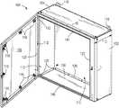
- FIG. 1is a perspective view of an enclosure according to a first embodiment of the present disclosure. A door of the enclosure is shown open.
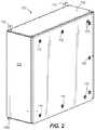
- FIG. 2is a perspective view of the enclosure of FIG. 1 . The door of the enclosure is shown closed.
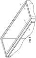
- FIG. 3is a detail view of a top edge of the enclosure as shown in FIG. 1 .
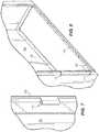
- FIG. 4is a detail view of a bottom edge of the enclosure as shown in FIG. 1 .
- FIG. 5is a perspective view of an upper portion of the enclosure with the upper end cap removed.
- FIG. 6is a perspective view of a lower portion of the enclosure with the door removed.
- FIG. 7is a detail view of a central one of the hinges on the enclosure body.
- FIG. 8is a perspective view of a lower portion of the enclosure with the door and lower end cap removed.
- FIG. 9is a perspective view of the enclosure body after initial forming and prior to attachment of upper and lower cross members.
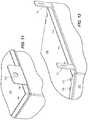
- FIG. 10Ais a first perspective view of the upper end cap.
- FIG. 10Bis a second perspective view of the upper end cap.
- FIG. 11is a detail perspective view of the top cap in position on a top flange of the enclosure body.
- FIG. 12is a detail perspective view of a rear edge portion of the upper end cap in position on the enclosure body.
- FIG. 13is a perspective view of a bottom cap.
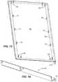
- FIG. 14is a perspective view of a cross member of the enclosure body.
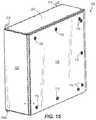
- FIG. 15is a first perspective view of an enclosure having an enclosure body with integral upper and lower mounting flanges.
- FIG. 16is a second perspective view of the enclosure of FIG. 15 .
- FIG. 17is a front view of the enclosure of FIGS. 15 and 16 , with a door and top cap removed.
- FIG. 18is a top view of the enclosure of FIGS. 15 and 16 , with the door and top cap removed.
- FIG. 19is a perspective view of the enclosure of FIGS. 15 and 16 , with the door and top cap removed.
- FIG. 20is a perspective view of the upper mounting flanges on the enclosure body.
- FIG. 21is a perspective view of an upper end cap for use with an enclosure body.
- FIGS. 1 and 2illustrate an enclosure 100 having a body 102 , upper and lower end caps 104 , 106 , and a door 108 for selectively opening and closing an opening 110 formed in the body 102 .
- the enclosure 100is formed generally as a rectangular (or square) prism, defining a length L, a width W, and a depth D.
- the enclosure 100is easily adapted to constructions having different H:W:D combinations, and it will be understood that the drawings illustrate only one such exemplary combination.
- the body 102is formed to include a front panel, a back panel, and two side panels that span between the front and back panels, and the opening 110 is formed in the front panel, which spans the length and width dimensions L, W.
- the panels of the body 102are sheet-formed, and the enclosure 100 as a whole is void of any separate frame supporting the panels of the body 102 .
- the door 108is shown open in FIG. 1 , in which configuration access is provided to an interior space of the enclosure 100 . With the door 108 closed, as in FIG. 2 , the interior space is sealed from the outside environment as discussed in further detail below.
- the door 108is hingedly attached to the body 102 in the illustrated construction to allow the door 108 to pivot or swing with respect to the body 102 .
- the attachmentcan include any number of hinges, or a continuous hinging along the length of the joint between the body 102 and the door 108 .
- the enclosure 100includes a first or upper hinge 112 ( FIG.
- Each hinge 112can be formed in part by an integral shaped extension of the body 102 or the door 108 , respectively, which interlace with each other and receive a hinge pin.
- FIGS. 6-8illustrate the hinge formation feature in further detail, with respect to the body 102 .
- the door 108can be secured to or released from the body 102 by one or more latches or hasps 116 , e.g., quarter-turn latches as shown.
- the illustrated latches 116are provided along the top edge, the bottom edge, and the free edge of the door 108 spaced across from the hinges 112 , e.g., each edge having multiple latches 116 .
- the enclosure 100can have a variety of alternate latch arrangements.
- Mounting brackets 118can be provided at various locations along the enclosure 100 to facilitate attachment of the enclosure 100 to a fixed building structure or machine, for example.
- Each mounting bracket 118can include an opening in the form of a hole, slot, etc., although other mounting structures are optional.
- the enclosure 100conforms to one or more industry standards for protecting its contents from intrusion of foreign matter such as water, dust, dirt, etc.
- standardsmay be set by the National Electrical Manufacturers Association (NEMA), International Electrotechnical Commission (IEC), or Underwriters Laboratories, Inc. (UL).
- NEMANational Electrical Manufacturers Association
- IECInternational Electrotechnical Commission
- ULUnderwriters Laboratories, Inc.
- Exemplary NEMA ratingsinclude Type 1, Type 3, Type 3R, Type 4, Type 12, etc.
- exemplary UL ratingsinclude UL50E.
- Such ratingsrequire testing of water-tightness, which simulate the ability for the enclosure to maintain a water-tight seal when exposed to windblown rain, splashing, hose spray, sleet, etc.
- water-tightshall refer to being sealed from water intrusion to meet at least one such rating of NEMA, IEC, or UL.
- the door 108In order for the enclosure 100 to meet such a rating, the door 108 must seal to the body 102 , and thus, a gasket 120 is provided ( FIG. 1 ).
- the gasket 120is illustrated as being provided on the door 108 for selective contact with the body 102 when the door 108 is closed. However, the gasket 120 is provided on the body 102 in other constructions. Likewise, it is conceived to have gaskets on both the body 102 and the door 108 .
- the gasket 120is formed from any suitable sealing material and may be a compressible material softer than the material of the body 102 and the door 108 (e.g., sheet metal).
- One exemplary gasket materialis a flexible polyurethane foam material. Such a foam material can be an addition-curing two-component system, for example a FERMAPOR® K31 product available from Sonderhoff Chemicals GmbH, GmbH, Germany.
- the gasket 120can be a RAKU-PUR® foam gasket product (e.g., RAKU-PUR 32-3250) available from RAMPF Giessharze GmbH, Grafenberg, Germany.
- the gasket 120can be provided on the enclosure 100 using formed-in-place foam gasket (FIPFG) technology.
- FPFGformed-in-place foam gasket
- the gasket 120is 0.500 in. wide and 0.250 in. high.
- the gasket 120is a peripheral gasket extending in a loop and conforming to the shape of the opening 110 .
- the body 102includes a raised lip or ridge 122 that is aligned for contacting the gasket 120 when the door 108 is closed. Pressure on the gasket 120 can be maintained by the closed latches 116 .
- the body 102includes a first or upper ledge 124 for receiving the upper end cap 104 at the top end of the body 102 and a second or lower ledge 126 for receiving the lower end cap 106 at the bottom end of the body 102 .
- Each ledge 124 , 126is formed as a peripheral flange about the width and depth dimensions of the enclosure 100 .
- the ledges 124 , 126lie in respective parallel planes at the ends of the enclosure 100 , both planes being perpendicular to the front, rear, and side panels.
- the ledges 124 , 126can be provided with a plurality of dispersed apertures as shown for connection of the upper and lower end caps 104 , 106 .
- the upper and lower end caps 104 , 106can be attached to the respective ledges 124 , 126 with individual fasteners 128 ( FIG. 6 ), e.g., threaded fasteners or rivets, including closed-end self-sealing rivets.
- the rivetscan be AD H series POP® rivets available from Emhart Teknologies, Shelton, Conn., for example AD 55 H.
- the rivetsmay have a polyurethane resin seal incorporated therewith (e.g., Rimlex® 620B available from Anochrome Group, Wolverhampton, UK).
- a top gasket 134is provided between the upper end cap 104 and the upper ledge 124
- a bottom gasket 136is provided between the lower end cap 106 and the lower ledge 126 , for sealing of the caps to the body 102 .
- the gaskets 134 , 136can be of a similar construction to the gasket 120 described above.
- the gaskets 134 , 136can be provided on the ledges 124 , 126 (as shown in FIG. 5 ) or on the caps 104 , 106 , respectively.
- gaskets 134 , 136each of which is formed as a continuous loop, is outboard of the fasteners 128 such that the fastener apertures are within the sealed space created by the gaskets 134 , 136 . There is no welding provided in the attachment of the upper and lower end caps 104 , 106 to the body 102 .
- the front, back and side panels of the body 102can be integrally formed from a single material sheet, e.g., through stamping processes, as shown in FIG. 9 .
- the body 102can be stamped into a block letter C-shape formed by two separate, spaced sections or flanks of the front panel, the two side panels, and the back panel.
- Also integrally formed from the same sheet along with the front, back, and side panelsare the lengthwise portions of the seal ridge 122 and the hinges 112 .
- the upper and lower ledges 124 , 126are also integrally formed as bent extensions of the front, back, and side panels.
- the ledges 124 , 126are not separately formed and attached (e.g., by welding) to the front, back, and side panels of the body 102 .
- the ledges 124 , 126themselves may be welded at corner miter joints to join various sections of folded-over material that combine to form each ledge 124 , 126 .
- these corner welds at the upper and lower ledges 124 , 126may be the only welded joints on the body 102 in the form shown in FIG. 9 , and thus, the body 102 is void of any lengthwise welds.
- the total length of the welds on the body 102may be less than the perimeter length of one end of the enclosure 100 (i.e., 2W+2D).
- the enclosure 100can be void of any single weld seam that spans the length L, void of any single weld seam that spans the width W, and void of any single weld seam that spans the depth D. Weld seams are indicated by dashed lines in FIGS. 3-6 and 8 . Reducing the amount of welding in the construction of the enclosure 100 limits not only the time and labor necessary to produce the welds, but to subsequently dress the welds, e.g., by grinding, polishing, etc.
- the gaskets 120 , 134 , 136can seal to meet the various NEMA, or UL standards, without any dressing of the welds. Rather, the manufacturing process may include application of the welds (e.g., by robotic welding, and optionally robotic laser welding), followed only by surface treatment (e.g., cleaning and/or coating, for example paint or powder coat) and assembly of the end caps 104 , 106 and the door 108 to the body 102 .
- surface treatmente.g., cleaning and/or coating, for example paint or powder coat
- weld seamscan be less than 100 cm (39.4 in), and even less than 90 cm (35.4 in) or less than 80 cm (31.5 in), for an enclosure having a volume of 20 liters (0.7 cu. ft.), 30 liters (1 cu. ft.), or more.
- the upper and lower cross members 144 , 146can have a similar or identical construction (see FIG. 14 ), and may be stamped sheet metal parts (e.g., of the same gauge as the body 102 ).
- the upper and lower cross members 144 , 146can each have multiple bends in the cross-section, thus forming the remaining portions of the seal ridge 122 surrounding the opening 110 .
- the upper and lower cross members 144 , 146can further form the connecting segments of the upper and lower ledges 124 , 126 .
- the upper end cap 104can be formed to include the mounting brackets 118 in some constructions.
- the upper end cap 104can be an integrally-stamped sheet, including the panel that closes the open end of the body 102 and the mounting brackets 118 .
- the mounting brackets 118can be formed separately from the end cap 104 and joined (e.g., by welding), to the end cap 104 and/or to the body 102 .
- the shapeis primarily flat throughout a majority central area of the cap 104 .
- all of the peripheral edging of the upper end cap 104is bent with a downward pitch angle ⁇ from a plane defined by a central portion of the upper end cap 104 (see FIGS. 10A and 10B ).
- the angle ⁇can be an acute angle, and in some constructions, at least 10 degrees and not more than 45 degrees.
- the peripheral edgingcan optionally be flush with the front, back, and side panels of the body 102 , or may create an overhang with respect thereto.
- the upper end cap 104does not extend down to lie directly on or against the front, back, and side panels. As shown in FIGS.
- the upper end cap 104includes through holes for the fasteners 128 , which may be rivets, or bolt-and-nut pairs, for example. However, through holes are not required in all constructions, as the upper end cap 104 can optionally have embedded (e.g., pressed-in) studs for the fasteners 128 —for example, threaded stud fasteners 128 as shown in the lower end cap 106 of FIG. 13 , which engage nuts to secure the upper end cap 104 to the body 102 .
- embedded (e.g., pressed-in) studs for the fasteners 128for example, threaded stud fasteners 128 as shown in the lower end cap 106 of FIG. 13 , which engage nuts to secure the upper end cap 104 to the body 102 .
- the lower end cap 106 as shown in FIG. 13features the same pitched edges as the upper end cap 104 , although not required in other constructions.
- the upper and lower end caps 104 , 106can be uniform and interchangeable in some constructions, whether having the through holes for separate fasteners or having the embedded studs.
- mounting brackets 118 Aare also optionally provided on the lower end cap 106 .
- the mounting brackets 118 Acan have the same construction as the upper end cap mounting brackets 118 or an alternate construction, e.g., with slots or elongated holes vs. circular holes.
- the mounting brackets 118 Acan be formed separately from the end cap 106 and joined (e.g., by welding), to the end cap 106 and/or to the body 102 .
- the mounting brackets 118 , 118 A of both end caps 104 , 106are used to mount the enclosure 100 , while in other constructions, only one set of the mounting brackets are used.
- the enclosure 200 of FIGS. 15-21is similar to the enclosure 100 as described above.
- the upper mounting brackets 218are formed separately from the body stamping and later attached thereto, e.g., by welding and/or fastener(s) to the back body panel.
- a second set of lower mounting brackets 218 Aare provided to extend outwardly from the lower end of the body 102 .
- the lower mounting brackets 218 Afeature elongated holes or open slots for mounting adjustability.
- the lower mounting brackets 218 Acan be attached to the body stamping by welding and/or fastener(s), as with the upper mounting brackets 218 .
- the upper and lower end caps 204 , 206feature no mounting flanges, but rather, each is simply a panel shaped and sized to close off the open end of the body 102 .
- the upper end cap 204can include fastener apertures as shown in FIG. 21 , embedded fasteners, or combinations thereof, all of which are inboard of the gasket 134 .
- the gasket 134is shown in FIG. 21 as applied to the upper end cap 204 , but the gasket 134 may alternately be applied to the upper ledge 124 as shown in FIGS. 18 and 19 .
- the lower end cap 206can take on any of the various features described for the upper and lower end caps 104 , 106 , 204 , and may optionally be interchangeable with the upper end cap 204 .
Landscapes
- Engineering & Computer Science (AREA)
- Microelectronics & Electronic Packaging (AREA)
- Power Engineering (AREA)
- Patch Boards (AREA)
- Casings For Electric Apparatus (AREA)
Abstract
Description
Claims (19)
Priority Applications (1)
| Application Number | Priority Date | Filing Date | Title |
|---|---|---|---|
| US16/547,057US10912217B2 (en) | 2018-08-22 | 2019-08-21 | Enclosure for electrical equipment |
Applications Claiming Priority (2)
| Application Number | Priority Date | Filing Date | Title |
|---|---|---|---|
| US201862721058P | 2018-08-22 | 2018-08-22 | |
| US16/547,057US10912217B2 (en) | 2018-08-22 | 2019-08-21 | Enclosure for electrical equipment |
Publications (2)
| Publication Number | Publication Date |
|---|---|
| US20200068736A1 US20200068736A1 (en) | 2020-02-27 |
| US10912217B2true US10912217B2 (en) | 2021-02-02 |
Family
ID=69583805
Family Applications (1)
| Application Number | Title | Priority Date | Filing Date |
|---|---|---|---|
| US16/547,057ActiveUS10912217B2 (en) | 2018-08-22 | 2019-08-21 | Enclosure for electrical equipment |
Country Status (1)
| Country | Link |
|---|---|
| US (1) | US10912217B2 (en) |
Cited By (2)
| Publication number | Priority date | Publication date | Assignee | Title |
|---|---|---|---|---|
| US20230120027A1 (en)* | 2021-10-18 | 2023-04-20 | Hardcraft Industries, Inc. | Metal enclosure for electrical components |
| USD1083934S1 (en)* | 2022-06-08 | 2025-07-15 | Mega Media Factory, LLC | Enclosure with security and weatherproofing |
Families Citing this family (10)
| Publication number | Priority date | Publication date | Assignee | Title |
|---|---|---|---|---|
| US10779422B2 (en)* | 2017-09-18 | 2020-09-15 | Marlen International, Inc. | Sealing assembly for wash-down electrical component enclosures |
| USD903665S1 (en)* | 2018-02-01 | 2020-12-01 | Hewlett-Packard Development Company, L.P. | Computer |
| USD920330S1 (en)* | 2018-04-18 | 2021-05-25 | Seagate Technology Llc | Storage device |
| TWD201841S (en)* | 2019-05-24 | 2020-01-01 | 威剛科技股份有限公司 | Part of computer case |
| USD1012922S1 (en)* | 2019-08-26 | 2024-01-30 | Hewlett-Packard Development Company, L.P. | Computer chassis |
| US11310923B2 (en)* | 2020-01-06 | 2022-04-19 | Enclosures Unlimited Inc. | Enclosure for electrical equipment |
| USD1027934S1 (en)* | 2020-10-30 | 2024-05-21 | William Nicholas Donato | Desktop computer |
| USD1013645S1 (en)* | 2021-01-25 | 2024-02-06 | Hyundai Tech Co., Ltd. | Safety switch enclosure |
| USD1042437S1 (en)* | 2022-01-05 | 2024-09-17 | Burak Barmanbek | Casing |
| USD1095476S1 (en)* | 2024-01-09 | 2025-09-30 | FZ United LLC | Electronic equipment cover |
Citations (62)
| Publication number | Priority date | Publication date | Assignee | Title |
|---|---|---|---|---|
| US3444345A (en) | 1967-06-29 | 1969-05-13 | Hubbell Inc Harvey | Electrical wiring device with positive locking cover |
| US4445622A (en) | 1982-07-09 | 1984-05-01 | Leonardo Sideri | Self-locking pilfer proof container |
| US5194691A (en) | 1989-11-13 | 1993-03-16 | Gichner Systems Group, Inc. | Gasket and cabinet for providing EMI/RFI shielding |
| US5292189A (en) | 1991-11-27 | 1994-03-08 | Federal-Hoffman, Inc. | Sub-panel guide system for electrical enclosure |
| US5536079A (en) | 1991-05-22 | 1996-07-16 | Asea Brown Boveri Ltd. | Cabinet |
| US5547272A (en) | 1995-04-24 | 1996-08-20 | At&T Global Information Solutions Company | Modular cabinet bezel |
| US5682017A (en) | 1995-05-08 | 1997-10-28 | The Wiremold Company | Metal outlet box with snap together base and cover |
| US5886868A (en) | 1996-10-10 | 1999-03-23 | Eaton Corporation | Electrical distribution panel enclosure |
| US5914460A (en) | 1998-02-19 | 1999-06-22 | Siemens Energy & Automation, Inc. | Weatherproof enclosure |
| US5971511A (en) | 1996-03-13 | 1999-10-26 | Rittal-Werk Rudolf Loh Gmbh & Co. Kg | Control box with a frame structure |
| US6000464A (en) | 1997-03-12 | 1999-12-14 | Interdigital Technology Corporation | Electronic component cooling system |
| US6110086A (en) | 1991-04-11 | 2000-08-29 | Moran, Jr.; Thomas F. | Method of manufacturing plastic enclosures |
| US20010033379A1 (en)* | 2000-02-25 | 2001-10-25 | Hach Company | Optical gasket system |
| US6374912B1 (en) | 1998-12-30 | 2002-04-23 | Lucent Technologies | Deep drawn enclosure with integrated heatsink and fastening details |
| US20020153373A1 (en) | 2001-04-20 | 2002-10-24 | Bernie Traut | Electrical enclosure |
| US20030090182A1 (en) | 2001-11-14 | 2003-05-15 | Johnson Kristianne E. | Interchangeable customized bezel |
| US6605777B1 (en) | 2002-07-29 | 2003-08-12 | Amco Engineering Co. | Earthquake-resistant electronic equipment frame |
| US6657861B2 (en) | 2000-02-23 | 2003-12-02 | Krone Gmbh | Distribution cabinet |
| US6877827B2 (en) | 2001-07-06 | 2005-04-12 | Rittal Gmbh & Co. Kg | Switch cabinet with a rack |
| US6879483B2 (en) | 2003-08-29 | 2005-04-12 | Eaton Corporation | Outdoor electrical enclosure and hood therefor |
| US6881898B2 (en) | 2001-03-02 | 2005-04-19 | Liebert Corporation | Remote distribution cabinet |
| US6924572B2 (en) | 2003-02-06 | 2005-08-02 | Emerson Electric Co. | Weather protected modular motor enclosure |
| US20060037773A1 (en) | 2004-07-28 | 2006-02-23 | Cosmo Castaldo | Weatherproof electrical enclosure |
| US20060119239A1 (en) | 2004-06-22 | 2006-06-08 | Werwick V P | Modular frame and enclosure system |
| US7068516B2 (en) | 2004-02-06 | 2006-06-27 | Chan Eric K D | Enclosure with pre-formed interchangeable panels |
| US7071409B2 (en) | 1998-03-06 | 2006-07-04 | Hoffman Enclosures, Inc. | Electrical enclosure having improved sealing and shielding component and method of manufacture thereof |
| US7075003B2 (en) | 2004-07-01 | 2006-07-11 | Eaton Corporation | Outdoor electrical enclosure and moisture-resistant flange and side assembly structures therefor |
| US20070175648A1 (en) | 2003-04-03 | 2007-08-02 | Melquisedec Francisquini | Improvement to metallic cross sections for the manufacture of housing for electrical panels |
| US7263869B2 (en) | 2000-08-17 | 2007-09-04 | Industrial Origami, Inc. | Method for forming sheet material with bend controlling grooves defining a continuous web across a bend line |
| US7276659B2 (en) | 2005-05-31 | 2007-10-02 | Hoffman Enclosures, Inc. | Enclosure having a closure member |
| US20090100894A1 (en) | 2007-09-22 | 2009-04-23 | Industrial Origami, Inc. | Sheet of Material with Fluid-Resistant Bend Controlling Displacements and Method of Forming the Same |
| US7532482B2 (en) | 2002-05-10 | 2009-05-12 | Purcell Systems, Inc. | Remote enclosure systems and methods of production thereof |
| US20110147037A1 (en) | 2009-12-21 | 2011-06-23 | Leviton Manufacturing Co., Inc. | Interchangeable decorative bezel for wiring device |
| US8022319B2 (en) | 2007-09-21 | 2011-09-20 | Siemens Industry, Inc. | Handle operator linkage with sealing means |
| US20120055924A1 (en)* | 2010-09-08 | 2012-03-08 | Abb Ag | Electrical switchgear cabinet |
| US8148648B2 (en) | 2008-06-11 | 2012-04-03 | Adc Telecommunications, Inc. | Combination extruded and cast metal outdoor electronics enclosure |
| US20120212883A1 (en)* | 2011-02-22 | 2012-08-23 | Ip Holdings, Llc | Electronic controller box |
| US8456814B2 (en) | 2011-02-28 | 2013-06-04 | Hubbell Incorporated | Enclosure for an electrical system |
| US20130264146A1 (en)* | 2012-04-04 | 2013-10-10 | Brian S. Nason | Acoustic module for enclosure panel |
| US8599540B2 (en) | 2011-09-26 | 2013-12-03 | Futurewei Technologies, Inc. | Modular system and framework for supporting an enclosure |
| US20140001932A1 (en) | 2012-06-29 | 2014-01-02 | Nathan L. Westby | Modular Outdoor Enclosure and Gravity Damper System |
| US8702184B2 (en) | 2007-10-01 | 2014-04-22 | Hoffman Enclosures, Inc. | Locking mechanism for configurable enclosure |
| US20140124259A1 (en) | 2012-11-06 | 2014-05-08 | M.C. Dean, Inc. | Junction box with integrated conduit supports |
| US8802978B2 (en) | 2006-03-13 | 2014-08-12 | Panduit Corp. | Network cabinet |
| US8891228B2 (en) | 2011-02-28 | 2014-11-18 | Hubbell Incorporated | Enclosure system and method for facilitating installation of electrical equipment |
| US9066586B2 (en) | 2009-08-28 | 2015-06-30 | Gregory Skovira | Modular enclosure |
| US9196430B2 (en) | 2012-11-16 | 2015-11-24 | Cooper Technologies Company | Electrical circuit protection device enclosure assembly and kit with device compatibility attachment |
| US9247658B2 (en) | 2011-08-10 | 2016-01-26 | Integra Enclosures Llc | Locking enclosure, stiffening ring, and vertical mounting stiffeners for securing components |
| US20160049778A1 (en) | 2014-08-18 | 2016-02-18 | John P. Moench | Recessed fixture enclosure |
| US9272821B2 (en) | 2013-09-13 | 2016-03-01 | Cooper Technologies Company | Fastening devices for explosion-proof enclosures |
| US20160086710A1 (en)* | 2014-09-18 | 2016-03-24 | Abb Technology Ag | Single piece frame for transformer core/coil assembly |
| US20160113126A1 (en)* | 2013-08-27 | 2016-04-21 | Huawei Technologies Co., Ltd. | Cabinet |
| US20160206492A1 (en)* | 2014-12-11 | 2016-07-21 | Edward R. di Girolamo | Multiplace hyperbaric chamber systems and methods |
| US20160238303A1 (en)* | 2015-02-17 | 2016-08-18 | Metro Industries Inc. | Mobile cabinet with insulation |
| US9455560B1 (en) | 2013-10-11 | 2016-09-27 | Pepperl+Fuchs, Inc. | Closure seal method and apparatus for wall mount enclosure |
| US20160368655A1 (en) | 2015-06-19 | 2016-12-22 | Hubbell Incorporated | Enclosures having sloping and convex curved tops |
| US9553435B2 (en) | 2010-12-22 | 2017-01-24 | Cooper Technologies Company | Manifold for controlling airflow within an explosion-proof enclosure |
| US9559501B2 (en) | 2011-07-11 | 2017-01-31 | General Electric Company | Housing assembly and method of assembling same |
| US9603269B2 (en) | 2015-01-22 | 2017-03-21 | Rockwell Automation Technologies, Inc. | Modular enclosure and construction method |
| US9678292B2 (en) | 2006-02-13 | 2017-06-13 | Commscope Technologies Llc | Termination module with termination leg and management leg |
| US9745794B2 (en) | 2013-09-16 | 2017-08-29 | Jeffrey S. Ellingson | Apparatus for sealing door of an enclosure |
| US20170261184A1 (en) | 2013-11-15 | 2017-09-14 | Osram Sylvania Inc. | Enclosure with grommetless strain relief |
Family Cites Families (1)
| Publication number | Priority date | Publication date | Assignee | Title |
|---|---|---|---|---|
| US8867234B2 (en)* | 2007-07-19 | 2014-10-21 | Qwest Communications International Inc. | Protective telecommunications enclosure systems and methods |
- 2019
- 2019-08-21USUS16/547,057patent/US10912217B2/enactiveActive
Patent Citations (62)
| Publication number | Priority date | Publication date | Assignee | Title |
|---|---|---|---|---|
| US3444345A (en) | 1967-06-29 | 1969-05-13 | Hubbell Inc Harvey | Electrical wiring device with positive locking cover |
| US4445622A (en) | 1982-07-09 | 1984-05-01 | Leonardo Sideri | Self-locking pilfer proof container |
| US5194691A (en) | 1989-11-13 | 1993-03-16 | Gichner Systems Group, Inc. | Gasket and cabinet for providing EMI/RFI shielding |
| US6110086A (en) | 1991-04-11 | 2000-08-29 | Moran, Jr.; Thomas F. | Method of manufacturing plastic enclosures |
| US5536079A (en) | 1991-05-22 | 1996-07-16 | Asea Brown Boveri Ltd. | Cabinet |
| US5292189A (en) | 1991-11-27 | 1994-03-08 | Federal-Hoffman, Inc. | Sub-panel guide system for electrical enclosure |
| US5547272A (en) | 1995-04-24 | 1996-08-20 | At&T Global Information Solutions Company | Modular cabinet bezel |
| US5682017A (en) | 1995-05-08 | 1997-10-28 | The Wiremold Company | Metal outlet box with snap together base and cover |
| US5971511A (en) | 1996-03-13 | 1999-10-26 | Rittal-Werk Rudolf Loh Gmbh & Co. Kg | Control box with a frame structure |
| US5886868A (en) | 1996-10-10 | 1999-03-23 | Eaton Corporation | Electrical distribution panel enclosure |
| US6000464A (en) | 1997-03-12 | 1999-12-14 | Interdigital Technology Corporation | Electronic component cooling system |
| US5914460A (en) | 1998-02-19 | 1999-06-22 | Siemens Energy & Automation, Inc. | Weatherproof enclosure |
| US7071409B2 (en) | 1998-03-06 | 2006-07-04 | Hoffman Enclosures, Inc. | Electrical enclosure having improved sealing and shielding component and method of manufacture thereof |
| US6374912B1 (en) | 1998-12-30 | 2002-04-23 | Lucent Technologies | Deep drawn enclosure with integrated heatsink and fastening details |
| US6657861B2 (en) | 2000-02-23 | 2003-12-02 | Krone Gmbh | Distribution cabinet |
| US20010033379A1 (en)* | 2000-02-25 | 2001-10-25 | Hach Company | Optical gasket system |
| US7263869B2 (en) | 2000-08-17 | 2007-09-04 | Industrial Origami, Inc. | Method for forming sheet material with bend controlling grooves defining a continuous web across a bend line |
| US6881898B2 (en) | 2001-03-02 | 2005-04-19 | Liebert Corporation | Remote distribution cabinet |
| US20020153373A1 (en) | 2001-04-20 | 2002-10-24 | Bernie Traut | Electrical enclosure |
| US6877827B2 (en) | 2001-07-06 | 2005-04-12 | Rittal Gmbh & Co. Kg | Switch cabinet with a rack |
| US20030090182A1 (en) | 2001-11-14 | 2003-05-15 | Johnson Kristianne E. | Interchangeable customized bezel |
| US7532482B2 (en) | 2002-05-10 | 2009-05-12 | Purcell Systems, Inc. | Remote enclosure systems and methods of production thereof |
| US6605777B1 (en) | 2002-07-29 | 2003-08-12 | Amco Engineering Co. | Earthquake-resistant electronic equipment frame |
| US6924572B2 (en) | 2003-02-06 | 2005-08-02 | Emerson Electric Co. | Weather protected modular motor enclosure |
| US20070175648A1 (en) | 2003-04-03 | 2007-08-02 | Melquisedec Francisquini | Improvement to metallic cross sections for the manufacture of housing for electrical panels |
| US6879483B2 (en) | 2003-08-29 | 2005-04-12 | Eaton Corporation | Outdoor electrical enclosure and hood therefor |
| US7068516B2 (en) | 2004-02-06 | 2006-06-27 | Chan Eric K D | Enclosure with pre-formed interchangeable panels |
| US20060119239A1 (en) | 2004-06-22 | 2006-06-08 | Werwick V P | Modular frame and enclosure system |
| US7075003B2 (en) | 2004-07-01 | 2006-07-11 | Eaton Corporation | Outdoor electrical enclosure and moisture-resistant flange and side assembly structures therefor |
| US20060037773A1 (en) | 2004-07-28 | 2006-02-23 | Cosmo Castaldo | Weatherproof electrical enclosure |
| US7276659B2 (en) | 2005-05-31 | 2007-10-02 | Hoffman Enclosures, Inc. | Enclosure having a closure member |
| US9678292B2 (en) | 2006-02-13 | 2017-06-13 | Commscope Technologies Llc | Termination module with termination leg and management leg |
| US8802978B2 (en) | 2006-03-13 | 2014-08-12 | Panduit Corp. | Network cabinet |
| US8022319B2 (en) | 2007-09-21 | 2011-09-20 | Siemens Industry, Inc. | Handle operator linkage with sealing means |
| US20090100894A1 (en) | 2007-09-22 | 2009-04-23 | Industrial Origami, Inc. | Sheet of Material with Fluid-Resistant Bend Controlling Displacements and Method of Forming the Same |
| US8702184B2 (en) | 2007-10-01 | 2014-04-22 | Hoffman Enclosures, Inc. | Locking mechanism for configurable enclosure |
| US8148648B2 (en) | 2008-06-11 | 2012-04-03 | Adc Telecommunications, Inc. | Combination extruded and cast metal outdoor electronics enclosure |
| US9066586B2 (en) | 2009-08-28 | 2015-06-30 | Gregory Skovira | Modular enclosure |
| US20110147037A1 (en) | 2009-12-21 | 2011-06-23 | Leviton Manufacturing Co., Inc. | Interchangeable decorative bezel for wiring device |
| US20120055924A1 (en)* | 2010-09-08 | 2012-03-08 | Abb Ag | Electrical switchgear cabinet |
| US9553435B2 (en) | 2010-12-22 | 2017-01-24 | Cooper Technologies Company | Manifold for controlling airflow within an explosion-proof enclosure |
| US20120212883A1 (en)* | 2011-02-22 | 2012-08-23 | Ip Holdings, Llc | Electronic controller box |
| US8456814B2 (en) | 2011-02-28 | 2013-06-04 | Hubbell Incorporated | Enclosure for an electrical system |
| US8891228B2 (en) | 2011-02-28 | 2014-11-18 | Hubbell Incorporated | Enclosure system and method for facilitating installation of electrical equipment |
| US9559501B2 (en) | 2011-07-11 | 2017-01-31 | General Electric Company | Housing assembly and method of assembling same |
| US9247658B2 (en) | 2011-08-10 | 2016-01-26 | Integra Enclosures Llc | Locking enclosure, stiffening ring, and vertical mounting stiffeners for securing components |
| US8599540B2 (en) | 2011-09-26 | 2013-12-03 | Futurewei Technologies, Inc. | Modular system and framework for supporting an enclosure |
| US20130264146A1 (en)* | 2012-04-04 | 2013-10-10 | Brian S. Nason | Acoustic module for enclosure panel |
| US20140001932A1 (en) | 2012-06-29 | 2014-01-02 | Nathan L. Westby | Modular Outdoor Enclosure and Gravity Damper System |
| US20140124259A1 (en) | 2012-11-06 | 2014-05-08 | M.C. Dean, Inc. | Junction box with integrated conduit supports |
| US9196430B2 (en) | 2012-11-16 | 2015-11-24 | Cooper Technologies Company | Electrical circuit protection device enclosure assembly and kit with device compatibility attachment |
| US20160113126A1 (en)* | 2013-08-27 | 2016-04-21 | Huawei Technologies Co., Ltd. | Cabinet |
| US9272821B2 (en) | 2013-09-13 | 2016-03-01 | Cooper Technologies Company | Fastening devices for explosion-proof enclosures |
| US9745794B2 (en) | 2013-09-16 | 2017-08-29 | Jeffrey S. Ellingson | Apparatus for sealing door of an enclosure |
| US9455560B1 (en) | 2013-10-11 | 2016-09-27 | Pepperl+Fuchs, Inc. | Closure seal method and apparatus for wall mount enclosure |
| US20170261184A1 (en) | 2013-11-15 | 2017-09-14 | Osram Sylvania Inc. | Enclosure with grommetless strain relief |
| US20160049778A1 (en) | 2014-08-18 | 2016-02-18 | John P. Moench | Recessed fixture enclosure |
| US20160086710A1 (en)* | 2014-09-18 | 2016-03-24 | Abb Technology Ag | Single piece frame for transformer core/coil assembly |
| US20160206492A1 (en)* | 2014-12-11 | 2016-07-21 | Edward R. di Girolamo | Multiplace hyperbaric chamber systems and methods |
| US9603269B2 (en) | 2015-01-22 | 2017-03-21 | Rockwell Automation Technologies, Inc. | Modular enclosure and construction method |
| US20160238303A1 (en)* | 2015-02-17 | 2016-08-18 | Metro Industries Inc. | Mobile cabinet with insulation |
| US20160368655A1 (en) | 2015-06-19 | 2016-12-22 | Hubbell Incorporated | Enclosures having sloping and convex curved tops |
Non-Patent Citations (7)
| Title |
|---|
| Anochrome Group, "Rimlex 620B Technical Data Sheet," publicly available at least as early as Aug. 16, 2018. |
| Emhart Teknologies, "PoP Closed End Rivets 5056 Aluminum Body/Steel Mandrel-Domed Head-Finish: Plain/Protective Coating," publicly available at least as early as Aug. 16, 2018. |
| Emhart Teknologies, "PoP Closed End Rivets 5056 Aluminum Body/Steel Mandrel—Domed Head—Finish: Plain/Protective Coating," publicly available at least as early as Aug. 16, 2018. |
| Forest City Technologies Inc., "Rimlex 620 BNA Product Data Sheet," publicly available at least as early as Aug. 16, 2018. |
| Rampf, "RAKU-PUR Foam Gaskets," publicly available prior to Aug. 22, 2018. |
| Sonderhoff Chemicals GMBH, "Fermapor K31 A-9230-2-VP / K31 B-4 Technical Data Sheet," <https://www.scandiloc.dk/datablade/pursealing/FermaporK31/> web page publicly available at least as early as Jul. 31, 2018. |
| Sonderhoff Chemicals GMBH, "Fermapor K31 Brochure," <https://www.sonderhoff.com/fileadmin/assets/images/infopool/Broschueren/sonderhoff_fermapork31_en.pdf> web page publicly available at least as early as Jul. 31, 2018. |
Cited By (2)
| Publication number | Priority date | Publication date | Assignee | Title |
|---|---|---|---|---|
| US20230120027A1 (en)* | 2021-10-18 | 2023-04-20 | Hardcraft Industries, Inc. | Metal enclosure for electrical components |
| USD1083934S1 (en)* | 2022-06-08 | 2025-07-15 | Mega Media Factory, LLC | Enclosure with security and weatherproofing |
Also Published As
| Publication number | Publication date |
|---|---|
| US20200068736A1 (en) | 2020-02-27 |
Similar Documents
| Publication | Publication Date | Title |
|---|---|---|
| US10912217B2 (en) | Enclosure for electrical equipment | |
| US11310923B2 (en) | Enclosure for electrical equipment | |
| US5536079A (en) | Cabinet | |
| US7441847B2 (en) | Metallic profile for the composition of structures for the assembly of cabinet/enclosures | |
| US20160073527A1 (en) | Cabinet frame enclosures, frame members and corresponding methods | |
| RU2335836C2 (en) | Updated metal transverse profile for feeder switchboard cases | |
| US10537038B2 (en) | Electrical panel enclosure including baffle to inhibit water ingress | |
| CA2150238C (en) | Cable lead-through member | |
| JP2016152250A (en) | Outdoor cabinet | |
| US6843543B2 (en) | Weatherproof enclosure with a modular structure | |
| US8562084B2 (en) | Enclosure corner seals and assemblies | |
| US8763834B2 (en) | Modular enclosure | |
| US9134040B2 (en) | Curb adapter | |
| US4769962A (en) | Controlled environment enclosure | |
| KR101089092B1 (en) | Frame for Control Cabinet | |
| US20070066214A1 (en) | Flush mounted frame for an access panel or register | |
| JP6106855B2 (en) | Electrical equipment storage box | |
| JP6370402B2 (en) | Housing, especially industrial housing | |
| US1933857A (en) | Shower bath cabinet | |
| JP6016834B2 (en) | Enclosure | |
| KR102413962B1 (en) | Door panel unit of metal enclosure for facility storage | |
| JPH109481A (en) | Door device for air conditioner inspection | |
| JP2002290081A (en) | Enclosure | |
| JP3802552B1 (en) | Roof structure for cubicle repair work | |
| WO2014075728A1 (en) | Ingress protected outdoor cabinet frame |
Legal Events
| Date | Code | Title | Description |
|---|---|---|---|
| AS | Assignment | Owner name:ENCLOSURES UNLIMITED INC., ILLINOIS Free format text:ASSIGNMENT OF ASSIGNORS INTEREST;ASSIGNORS:KELLY, PAUL;HANLEY, JOHN E.;BOPP, JEFFREY S.;AND OTHERS;REEL/FRAME:050121/0050 Effective date:20190820 | |
| FEPP | Fee payment procedure | Free format text:ENTITY STATUS SET TO UNDISCOUNTED (ORIGINAL EVENT CODE: BIG.); ENTITY STATUS OF PATENT OWNER: LARGE ENTITY | |
| STPP | Information on status: patent application and granting procedure in general | Free format text:DOCKETED NEW CASE - READY FOR EXAMINATION | |
| STPP | Information on status: patent application and granting procedure in general | Free format text:NON FINAL ACTION MAILED | |
| STPP | Information on status: patent application and granting procedure in general | Free format text:FINAL REJECTION MAILED | |
| STCV | Information on status: appeal procedure | Free format text:NOTICE OF APPEAL FILED | |
| STPP | Information on status: patent application and granting procedure in general | Free format text:DOCKETED NEW CASE - READY FOR EXAMINATION | |
| STPP | Information on status: patent application and granting procedure in general | Free format text:PUBLICATIONS -- ISSUE FEE PAYMENT VERIFIED | |
| STCF | Information on status: patent grant | Free format text:PATENTED CASE | |
| MAFP | Maintenance fee payment | Free format text:PAYMENT OF MAINTENANCE FEE, 4TH YEAR, LARGE ENTITY (ORIGINAL EVENT CODE: M1551); ENTITY STATUS OF PATENT OWNER: LARGE ENTITY Year of fee payment:4 | |
| AS | Assignment | Owner name:ENCLOSURES UNLIMITED, LLC, ILLINOIS Free format text:CORRECTIVE ASSIGNMENT TO CORRECT THE ASSIGNEE'S NAME INSIDE THE ASSIGNMENT DOCUMENT AND ON THE COVER SHEET PREVIOUSLY RECORDED AT REEL: 50121 FRAME: 50. ASSIGNOR(S) HEREBY CONFIRMS THE ASSIGNMENT;ASSIGNORS:KELLY, PAUL;HANLEY, JOHN E.;BOPP, JEFFREY S.;AND OTHERS;REEL/FRAME:069402/0621 Effective date:20190820 | |
| AS | Assignment | Owner name:JPMORGAN CHASE BANK, N.A., ILLINOIS Free format text:SECURITY INTEREST;ASSIGNOR:ENCLOSURES UNLIMITED LLC;REEL/FRAME:069543/0572 Effective date:20241210 | |
| AS | Assignment | Owner name:ENCLOSURES UNLIMITED LLC, ILLINOIS Free format text:CORRECTIVE ASSIGNMENT TO CORRECT THE ASSIGNEE'S NAME BY REMOVING THE COMMA FROM BETWEEN UNLIMITED AND LLC PREVIOUSLY RECORDED ON REEL 69402 FRAME 621. ASSIGNOR(S) HEREBY CONFIRMS THE CORRECTIVE ASSIGNMENT;ASSIGNORS:KELLY, PAUL;HANLEY, JOHN E.;BOPP, JEFFREY S.;AND OTHERS;REEL/FRAME:070553/0073 Effective date:20190820 |