US10908272B2 - Reduced complexity FFT-based correlation for automotive radar - Google Patents
Reduced complexity FFT-based correlation for automotive radarDownload PDFInfo
- Publication number
- US10908272B2 US10908272B2US15/689,273US201715689273AUS10908272B2US 10908272 B2US10908272 B2US 10908272B2US 201715689273 AUS201715689273 AUS 201715689273AUS 10908272 B2US10908272 B2US 10908272B2
- Authority
- US
- United States
- Prior art keywords
- samples
- receiver
- frequency domain
- received
- radio signals
- Prior art date
- Legal status (The legal status is an assumption and is not a legal conclusion. Google has not performed a legal analysis and makes no representation as to the accuracy of the status listed.)
- Active, expires
Links
Images


Classifications
- G—PHYSICS
- G01—MEASURING; TESTING
- G01S—RADIO DIRECTION-FINDING; RADIO NAVIGATION; DETERMINING DISTANCE OR VELOCITY BY USE OF RADIO WAVES; LOCATING OR PRESENCE-DETECTING BY USE OF THE REFLECTION OR RERADIATION OF RADIO WAVES; ANALOGOUS ARRANGEMENTS USING OTHER WAVES
- G01S7/00—Details of systems according to groups G01S13/00, G01S15/00, G01S17/00
- G01S7/02—Details of systems according to groups G01S13/00, G01S15/00, G01S17/00 of systems according to group G01S13/00
- G01S7/28—Details of pulse systems
- G01S7/285—Receivers
- G01S7/288—Coherent receivers
- G01S7/2883—Coherent receivers using FFT processing
- G—PHYSICS
- G01—MEASURING; TESTING
- G01S—RADIO DIRECTION-FINDING; RADIO NAVIGATION; DETERMINING DISTANCE OR VELOCITY BY USE OF RADIO WAVES; LOCATING OR PRESENCE-DETECTING BY USE OF THE REFLECTION OR RERADIATION OF RADIO WAVES; ANALOGOUS ARRANGEMENTS USING OTHER WAVES
- G01S13/00—Systems using the reflection or reradiation of radio waves, e.g. radar systems; Analogous systems using reflection or reradiation of waves whose nature or wavelength is irrelevant or unspecified
- G01S13/02—Systems using reflection of radio waves, e.g. primary radar systems; Analogous systems
- G01S13/06—Systems determining position data of a target
- G01S13/08—Systems for measuring distance only
- G01S13/32—Systems for measuring distance only using transmission of continuous waves, whether amplitude-, frequency-, or phase-modulated, or unmodulated
- G01S13/34—Systems for measuring distance only using transmission of continuous waves, whether amplitude-, frequency-, or phase-modulated, or unmodulated using transmission of continuous, frequency-modulated waves while heterodyning the received signal, or a signal derived therefrom, with a locally-generated signal related to the contemporaneously transmitted signal
- G—PHYSICS
- G01—MEASURING; TESTING
- G01S—RADIO DIRECTION-FINDING; RADIO NAVIGATION; DETERMINING DISTANCE OR VELOCITY BY USE OF RADIO WAVES; LOCATING OR PRESENCE-DETECTING BY USE OF THE REFLECTION OR RERADIATION OF RADIO WAVES; ANALOGOUS ARRANGEMENTS USING OTHER WAVES
- G01S13/00—Systems using the reflection or reradiation of radio waves, e.g. radar systems; Analogous systems using reflection or reradiation of waves whose nature or wavelength is irrelevant or unspecified
- G01S13/02—Systems using reflection of radio waves, e.g. primary radar systems; Analogous systems
- G01S13/06—Systems determining position data of a target
- G01S13/08—Systems for measuring distance only
- G01S13/10—Systems for measuring distance only using transmission of interrupted, pulse modulated waves
- G01S13/26—Systems for measuring distance only using transmission of interrupted, pulse modulated waves wherein the transmitted pulses use a frequency- or phase-modulated carrier wave
- G01S13/28—Systems for measuring distance only using transmission of interrupted, pulse modulated waves wherein the transmitted pulses use a frequency- or phase-modulated carrier wave with time compression of received pulses
- G01S13/284—Systems for measuring distance only using transmission of interrupted, pulse modulated waves wherein the transmitted pulses use a frequency- or phase-modulated carrier wave with time compression of received pulses using coded pulses
- G01S13/288—Systems for measuring distance only using transmission of interrupted, pulse modulated waves wherein the transmitted pulses use a frequency- or phase-modulated carrier wave with time compression of received pulses using coded pulses phase modulated
- G—PHYSICS
- G01—MEASURING; TESTING
- G01S—RADIO DIRECTION-FINDING; RADIO NAVIGATION; DETERMINING DISTANCE OR VELOCITY BY USE OF RADIO WAVES; LOCATING OR PRESENCE-DETECTING BY USE OF THE REFLECTION OR RERADIATION OF RADIO WAVES; ANALOGOUS ARRANGEMENTS USING OTHER WAVES
- G01S13/00—Systems using the reflection or reradiation of radio waves, e.g. radar systems; Analogous systems using reflection or reradiation of waves whose nature or wavelength is irrelevant or unspecified
- G01S13/02—Systems using reflection of radio waves, e.g. primary radar systems; Analogous systems
- G01S13/06—Systems determining position data of a target
- G01S13/08—Systems for measuring distance only
- G01S13/32—Systems for measuring distance only using transmission of continuous waves, whether amplitude-, frequency-, or phase-modulated, or unmodulated
- G01S13/325—Systems for measuring distance only using transmission of continuous waves, whether amplitude-, frequency-, or phase-modulated, or unmodulated using transmission of coded signals, e.g. P.S.K. signals
- G—PHYSICS
- G01—MEASURING; TESTING
- G01S—RADIO DIRECTION-FINDING; RADIO NAVIGATION; DETERMINING DISTANCE OR VELOCITY BY USE OF RADIO WAVES; LOCATING OR PRESENCE-DETECTING BY USE OF THE REFLECTION OR RERADIATION OF RADIO WAVES; ANALOGOUS ARRANGEMENTS USING OTHER WAVES
- G01S13/00—Systems using the reflection or reradiation of radio waves, e.g. radar systems; Analogous systems using reflection or reradiation of waves whose nature or wavelength is irrelevant or unspecified
- G01S13/02—Systems using reflection of radio waves, e.g. primary radar systems; Analogous systems
- G01S13/06—Systems determining position data of a target
- G01S13/08—Systems for measuring distance only
- G01S13/32—Systems for measuring distance only using transmission of continuous waves, whether amplitude-, frequency-, or phase-modulated, or unmodulated
- G01S13/36—Systems for measuring distance only using transmission of continuous waves, whether amplitude-, frequency-, or phase-modulated, or unmodulated with phase comparison between the received signal and the contemporaneously transmitted signal
- G01S13/38—Systems for measuring distance only using transmission of continuous waves, whether amplitude-, frequency-, or phase-modulated, or unmodulated with phase comparison between the received signal and the contemporaneously transmitted signal wherein more than one modulation frequency is used
- G—PHYSICS
- G01—MEASURING; TESTING
- G01S—RADIO DIRECTION-FINDING; RADIO NAVIGATION; DETERMINING DISTANCE OR VELOCITY BY USE OF RADIO WAVES; LOCATING OR PRESENCE-DETECTING BY USE OF THE REFLECTION OR RERADIATION OF RADIO WAVES; ANALOGOUS ARRANGEMENTS USING OTHER WAVES
- G01S13/00—Systems using the reflection or reradiation of radio waves, e.g. radar systems; Analogous systems using reflection or reradiation of waves whose nature or wavelength is irrelevant or unspecified
- G01S13/02—Systems using reflection of radio waves, e.g. primary radar systems; Analogous systems
- G01S13/50—Systems of measurement based on relative movement of target
- G01S13/52—Discriminating between fixed and moving objects or between objects moving at different speeds
- G01S13/522—Discriminating between fixed and moving objects or between objects moving at different speeds using transmissions of interrupted pulse modulated waves
- G—PHYSICS
- G01—MEASURING; TESTING
- G01S—RADIO DIRECTION-FINDING; RADIO NAVIGATION; DETERMINING DISTANCE OR VELOCITY BY USE OF RADIO WAVES; LOCATING OR PRESENCE-DETECTING BY USE OF THE REFLECTION OR RERADIATION OF RADIO WAVES; ANALOGOUS ARRANGEMENTS USING OTHER WAVES
- G01S13/00—Systems using the reflection or reradiation of radio waves, e.g. radar systems; Analogous systems using reflection or reradiation of waves whose nature or wavelength is irrelevant or unspecified
- G01S13/02—Systems using reflection of radio waves, e.g. primary radar systems; Analogous systems
- G01S13/50—Systems of measurement based on relative movement of target
- G01S13/58—Velocity or trajectory determination systems; Sense-of-movement determination systems
- G01S13/581—Velocity or trajectory determination systems; Sense-of-movement determination systems using transmission of interrupted pulse modulated waves and based upon the Doppler effect resulting from movement of targets
- G01S13/582—Velocity or trajectory determination systems; Sense-of-movement determination systems using transmission of interrupted pulse modulated waves and based upon the Doppler effect resulting from movement of targets adapted for simultaneous range and velocity measurements
- G—PHYSICS
- G01—MEASURING; TESTING
- G01S—RADIO DIRECTION-FINDING; RADIO NAVIGATION; DETERMINING DISTANCE OR VELOCITY BY USE OF RADIO WAVES; LOCATING OR PRESENCE-DETECTING BY USE OF THE REFLECTION OR RERADIATION OF RADIO WAVES; ANALOGOUS ARRANGEMENTS USING OTHER WAVES
- G01S13/00—Systems using the reflection or reradiation of radio waves, e.g. radar systems; Analogous systems using reflection or reradiation of waves whose nature or wavelength is irrelevant or unspecified
- G01S13/02—Systems using reflection of radio waves, e.g. primary radar systems; Analogous systems
- G01S13/50—Systems of measurement based on relative movement of target
- G01S13/58—Velocity or trajectory determination systems; Sense-of-movement determination systems
- G01S13/583—Velocity or trajectory determination systems; Sense-of-movement determination systems using transmission of continuous unmodulated waves, amplitude-, frequency-, or phase-modulated waves and based upon the Doppler effect resulting from movement of targets
- G01S13/584—Velocity or trajectory determination systems; Sense-of-movement determination systems using transmission of continuous unmodulated waves, amplitude-, frequency-, or phase-modulated waves and based upon the Doppler effect resulting from movement of targets adapted for simultaneous range and velocity measurements
- G—PHYSICS
- G01—MEASURING; TESTING
- G01S—RADIO DIRECTION-FINDING; RADIO NAVIGATION; DETERMINING DISTANCE OR VELOCITY BY USE OF RADIO WAVES; LOCATING OR PRESENCE-DETECTING BY USE OF THE REFLECTION OR RERADIATION OF RADIO WAVES; ANALOGOUS ARRANGEMENTS USING OTHER WAVES
- G01S13/00—Systems using the reflection or reradiation of radio waves, e.g. radar systems; Analogous systems using reflection or reradiation of waves whose nature or wavelength is irrelevant or unspecified
- G01S13/88—Radar or analogous systems specially adapted for specific applications
- G01S13/89—Radar or analogous systems specially adapted for specific applications for mapping or imaging
- G01S13/90—Radar or analogous systems specially adapted for specific applications for mapping or imaging using synthetic aperture techniques, e.g. synthetic aperture radar [SAR] techniques
- G01S13/9004—SAR image acquisition techniques
- G01S13/9011—SAR image acquisition techniques with frequency domain processing of the SAR signals in azimuth
- G—PHYSICS
- G01—MEASURING; TESTING
- G01S—RADIO DIRECTION-FINDING; RADIO NAVIGATION; DETERMINING DISTANCE OR VELOCITY BY USE OF RADIO WAVES; LOCATING OR PRESENCE-DETECTING BY USE OF THE REFLECTION OR RERADIATION OF RADIO WAVES; ANALOGOUS ARRANGEMENTS USING OTHER WAVES
- G01S13/00—Systems using the reflection or reradiation of radio waves, e.g. radar systems; Analogous systems using reflection or reradiation of waves whose nature or wavelength is irrelevant or unspecified
- G01S13/88—Radar or analogous systems specially adapted for specific applications
- G01S13/93—Radar or analogous systems specially adapted for specific applications for anti-collision purposes
- G01S13/931—Radar or analogous systems specially adapted for specific applications for anti-collision purposes of land vehicles
- G—PHYSICS
- G01—MEASURING; TESTING
- G01S—RADIO DIRECTION-FINDING; RADIO NAVIGATION; DETERMINING DISTANCE OR VELOCITY BY USE OF RADIO WAVES; LOCATING OR PRESENCE-DETECTING BY USE OF THE REFLECTION OR RERADIATION OF RADIO WAVES; ANALOGOUS ARRANGEMENTS USING OTHER WAVES
- G01S7/00—Details of systems according to groups G01S13/00, G01S15/00, G01S17/00
- G01S7/02—Details of systems according to groups G01S13/00, G01S15/00, G01S17/00 of systems according to group G01S13/00
- G01S7/28—Details of pulse systems
- G01S7/285—Receivers
- G01S7/288—Coherent receivers
- G—PHYSICS
- G01—MEASURING; TESTING
- G01S—RADIO DIRECTION-FINDING; RADIO NAVIGATION; DETERMINING DISTANCE OR VELOCITY BY USE OF RADIO WAVES; LOCATING OR PRESENCE-DETECTING BY USE OF THE REFLECTION OR RERADIATION OF RADIO WAVES; ANALOGOUS ARRANGEMENTS USING OTHER WAVES
- G01S7/00—Details of systems according to groups G01S13/00, G01S15/00, G01S17/00
- G01S7/02—Details of systems according to groups G01S13/00, G01S15/00, G01S17/00 of systems according to group G01S13/00
- G01S7/28—Details of pulse systems
- G01S7/285—Receivers
- G01S7/292—Extracting wanted echo-signals
- G01S7/2921—Extracting wanted echo-signals based on data belonging to one radar period
- G—PHYSICS
- G01—MEASURING; TESTING
- G01S—RADIO DIRECTION-FINDING; RADIO NAVIGATION; DETERMINING DISTANCE OR VELOCITY BY USE OF RADIO WAVES; LOCATING OR PRESENCE-DETECTING BY USE OF THE REFLECTION OR RERADIATION OF RADIO WAVES; ANALOGOUS ARRANGEMENTS USING OTHER WAVES
- G01S7/00—Details of systems according to groups G01S13/00, G01S15/00, G01S17/00
- G01S7/02—Details of systems according to groups G01S13/00, G01S15/00, G01S17/00 of systems according to group G01S13/00
- G01S7/35—Details of non-pulse systems
- G01S7/352—Receivers
- G01S7/354—Extracting wanted echo-signals
- G—PHYSICS
- G01—MEASURING; TESTING
- G01S—RADIO DIRECTION-FINDING; RADIO NAVIGATION; DETERMINING DISTANCE OR VELOCITY BY USE OF RADIO WAVES; LOCATING OR PRESENCE-DETECTING BY USE OF THE REFLECTION OR RERADIATION OF RADIO WAVES; ANALOGOUS ARRANGEMENTS USING OTHER WAVES
- G01S7/00—Details of systems according to groups G01S13/00, G01S15/00, G01S17/00
- G01S7/02—Details of systems according to groups G01S13/00, G01S15/00, G01S17/00 of systems according to group G01S13/00
- G01S7/40—Means for monitoring or calibrating
- G01S7/4004—Means for monitoring or calibrating of parts of a radar system
- G—PHYSICS
- G01—MEASURING; TESTING
- G01S—RADIO DIRECTION-FINDING; RADIO NAVIGATION; DETERMINING DISTANCE OR VELOCITY BY USE OF RADIO WAVES; LOCATING OR PRESENCE-DETECTING BY USE OF THE REFLECTION OR RERADIATION OF RADIO WAVES; ANALOGOUS ARRANGEMENTS USING OTHER WAVES
- G01S7/00—Details of systems according to groups G01S13/00, G01S15/00, G01S17/00
- G01S7/02—Details of systems according to groups G01S13/00, G01S15/00, G01S17/00 of systems according to group G01S13/00
- G01S7/41—Details of systems according to groups G01S13/00, G01S15/00, G01S17/00 of systems according to group G01S13/00 using analysis of echo signal for target characterisation; Target signature; Target cross-section
- G01S7/415—Identification of targets based on measurements of movement associated with the target
- G01S2007/2883—
- G01S2007/356—
- G—PHYSICS
- G01—MEASURING; TESTING
- G01S—RADIO DIRECTION-FINDING; RADIO NAVIGATION; DETERMINING DISTANCE OR VELOCITY BY USE OF RADIO WAVES; LOCATING OR PRESENCE-DETECTING BY USE OF THE REFLECTION OR RERADIATION OF RADIO WAVES; ANALOGOUS ARRANGEMENTS USING OTHER WAVES
- G01S13/00—Systems using the reflection or reradiation of radio waves, e.g. radar systems; Analogous systems using reflection or reradiation of waves whose nature or wavelength is irrelevant or unspecified
- G01S13/88—Radar or analogous systems specially adapted for specific applications
- G01S13/93—Radar or analogous systems specially adapted for specific applications for anti-collision purposes
- G01S13/931—Radar or analogous systems specially adapted for specific applications for anti-collision purposes of land vehicles
- G01S2013/9327—Sensor installation details
- G01S2013/93271—Sensor installation details in the front of the vehicles
- G—PHYSICS
- G01—MEASURING; TESTING
- G01S—RADIO DIRECTION-FINDING; RADIO NAVIGATION; DETERMINING DISTANCE OR VELOCITY BY USE OF RADIO WAVES; LOCATING OR PRESENCE-DETECTING BY USE OF THE REFLECTION OR RERADIATION OF RADIO WAVES; ANALOGOUS ARRANGEMENTS USING OTHER WAVES
- G01S13/00—Systems using the reflection or reradiation of radio waves, e.g. radar systems; Analogous systems using reflection or reradiation of waves whose nature or wavelength is irrelevant or unspecified
- G01S13/88—Radar or analogous systems specially adapted for specific applications
- G01S13/93—Radar or analogous systems specially adapted for specific applications for anti-collision purposes
- G01S13/931—Radar or analogous systems specially adapted for specific applications for anti-collision purposes of land vehicles
- G01S2013/9327—Sensor installation details
- G01S2013/93272—Sensor installation details in the back of the vehicles
- G—PHYSICS
- G01—MEASURING; TESTING
- G01S—RADIO DIRECTION-FINDING; RADIO NAVIGATION; DETERMINING DISTANCE OR VELOCITY BY USE OF RADIO WAVES; LOCATING OR PRESENCE-DETECTING BY USE OF THE REFLECTION OR RERADIATION OF RADIO WAVES; ANALOGOUS ARRANGEMENTS USING OTHER WAVES
- G01S7/00—Details of systems according to groups G01S13/00, G01S15/00, G01S17/00
- G01S7/02—Details of systems according to groups G01S13/00, G01S15/00, G01S17/00 of systems according to group G01S13/00
- G01S7/35—Details of non-pulse systems
- G01S7/352—Receivers
- G01S7/356—Receivers involving particularities of FFT processing
Definitions
- the present inventionis directed to radar systems, and more particularly to radar systems for vehicles.
- a radar systemtypically operates by transmitting signals from one or more transmitters and then listening for the reflection of that signal from objects in the environment at one or more receivers. By comparing the transmitted signal with the received signal, a radar system can determine the distance to different objects. Using multiple transmissions, the velocity of an object can be determined. Using multiple transmitters and/or receivers, the angle (azimuth and/or elevation) of an object can be estimated.
- the present inventionprovides methods and a system for achieving better performance in a radar system implemented as a modulated continuous wave radar.
- An exemplary radar system of the present inventioncomputes various correlations with reduced complexity. Exemplary embodiments accomplish this by performing the correlation processing in the frequency domain, such that the transmitted signal and the received signal are correlated in the frequency domain.
- a radar sensing system for a vehicle in accordance with an embodiment of the present inventionincludes at least one transmitter, at least one receiver, at least one antenna, memory, and a controller.
- the at least one transmitteris configured for installation and use on a vehicle and transmits radio signals.
- the transmitted radio signalsare generated by up-converting a baseband transmitted signal.
- the at least one receiveris configured for installation and use on the vehicle and receives radio signals which include transmitted radio signals reflected from objects in the environment.
- the reflected radio signalsare down-converted, and then sampled and quantized using an analog-to-digital converter (ADC) to produce possibly complex baseband samples.
- ADCanalog-to-digital converter
- the resulting signal from the ADCis processed by a digital processor.
- the digital processorprocesses the received signal and transmitted signal in the frequency domain in order to produce a subset of correlations corresponding to a set of possible delays of the transmitted signal.
- the samplesare converted into the frequency domain through the use of a Fourier transform operation.
- a radar sensing system for a vehicle in accordance with an embodiment of the present inventionincludes a transmit pipeline comprising at least one transmitter configured to transmit radio signals, a receive pipeline configured for installation and use on the vehicle.
- the receive pipelinecomprises at least one receiver configured to receive radio signals that include the transmitted radio signals reflected from objects in the environment.
- Each of the at least one receivercomprises at least one analog-to-digital converter (ADC) configured to convert the received radio signals to digital received samples.
- ADCanalog-to-digital converter
- the digital received samplesare time domain received samples.
- Each of the at least one receiveris configured to correlate the received radio signals after the time domain received samples of the received radio signals have been converted into frequency domain received samples via a Fourier transform type of operation.
- a method of correlating received samples in a radar system for a vehicle in accordance with an embodiment of the present inventionincludes providing a radar system that includes (i) at least one transmitter configured for installation and use on a vehicle and configured to transmit radio signals, and (ii) at least one receiver configured for installation and use on the vehicle and configured to receive radio signals that include the transmitted radio signals reflected from objects in the environment.
- the radio signals received by each of the at least one receiverare converted into digital received samples.
- the samplesare converted using at least one analog-to-digital converter (ADC) as part of the at least one receiver.
- the digital received samplesare time domain received samples.
- the time domain received samples of the received radio signalsare converted into frequency domain received samples via a Fourier transform type of operation.
- the frequency domain received samplesare multiplied by a frequency domain version of the transmitted signal at each of the at least one receiver.
- a radar sensing system for a vehicle in accordance with an embodiment of the present inventionincludes a transmitter and a receiver.
- the transmitteris configured for installation and use on a vehicle and configured to transmit modulated radio signals.
- the radio signalsare modulated via a spreading code.
- the receiveris configured to receive radio signals that include the transmitted radio signals reflected from objects in the environment.
- the receiverincludes a first analog-to-digital converter (ADC) that is configured to convert the received radio signals into the received samples.
- the received samplesare time domain received samples.
- the receiverincludes a first Fourier transform module that is configured to convert the time domain received samples into frequency domain received samples.
- the receiverincludes a product module configured to multiply the frequency domain received radio signals with the corresponding transmitted signal.
- the product moduleis configured to output processed samples.
- the receiverfurther comprises an inverse Fourier transform type of module configured to convert the processed samples from the frequency domain to the time domain.
- the Fourier transform operationmay be performed through the use of a fast Fourier transform.
- a receiveris configured to divide received samples into blocks of samples, where a size of a block is smaller than a length of the spreading code.
- a receiveris configured to process a code sample either before or after the Fourier transform before the code sample is multiplied by the frequency domain samples of the received radio signals.
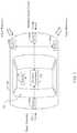
- FIG. 1is a plan view of an automobile equipped with a radar system in accordance with the present invention
- FIG. 2A and FIG. 2Bare block diagrams of a single transmitter and a single receiver in a radar system
- FIG. 3is a block diagram of a radar system with multiple transmitters and multiple receivers
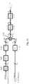
- FIG. 4is a block diagram illustrating the basic processing blocks of a transmitter and a receiver in a radar system in accordance with the present invention
- FIG. 5is a block diagram illustrating the basic processing blocks of a correlator as used in a radar receiver in accordance with the present invention
- FIG. 6is a block diagram illustrating the basic processing blocks of a plurality of correlators as used in a radar receiver in accordance with the present invention
- FIG. 7illustrates a matched filter used in a radar receiver in accordance with the present invention
- FIG. 8is a diagram illustrating a transmitted signal using an m-sequence of length 31 in accordance with the present invention.
- FIG. 9is a diagram illustrating an output of a matched filter with a single target in accordance with the present invention.
- FIG. 10is a diagram illustrating an output of a matched filter with two targets separated by more than a chip in equivalent delay in accordance with the present invention.
- FIG. 11is a block diagram of an exemplary FFT-based correlator of a receiver in which received signals are converted to frequency domain signals, multiplied component-by-component and then converted back into the time domain in accordance with the present invention
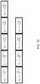
- FIG. 12illustrates received samples from an analog-to-digital converter that are organized into blocks, with the code values also organized into blocks in accordance with the present invention
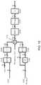
- FIG. 13is a block diagram of another exemplary FFT-based correlator in accordance with the present invention.
- FIG. 14is a block diagram of another exemplary FFT-based correlator in accordance with the present invention.
- FIG. 15is a block diagram of another exemplary FFT-based correlator in accordance with the present invention.
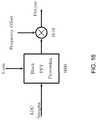
- FIG. 16is a block diagram of another exemplary FFT-based correlator in accordance with the present invention.
- a high-throughput correlationis provided through the use of a Fourier transform operation which converts complex samples into the frequency domain, such that the correlation can be performed in the frequency domain.
- a radar systemmay transmit a continuous signal or a pulsed signal.
- a pulsed radar systema signal is transmitted for a short duration during a first time period and then no signal is transmitted for a short duration during a subsequent second time period. This is repeated over and over.
- a receiverlistens for echoes or reflections from objects in the environment.
- a single antennais used for both a transmitter and a receiver, where the radar transmits with the transmitter on the single antenna and then listens with the receiver, via the same antenna, for a radio signal reflected from objects in the environment. This process is then repeated.
- a continuous wave radar systemwhere a signal is continuously transmitted. There may be an antenna for transmitting and a separate antenna for receiving.
- One type of continuous radar signalis known as a frequency-modulated continuous waveform (FMCW).
- FMCW radar systemthe transmitter of the radar system sends a continuous sinusoidal signal in which the frequency of the signal varies. This is sometimes called a chirp radar system.
- Mixing (multiplying) the radio signal reflected from a target/object with a replica of the transmitted signalresults in a CW signal with a frequency that represents the distance between the radar transmitter/receiver and the target. For example, by measuring the time difference between when a certain frequency was transmitted and when the received signal contained that frequency, the range to an object can be determined. By sweeping up in frequency and then down in frequency, the Doppler frequency can also be determined.
- phase-modulated continuous waveformFor this type of signal, a phase of a radio signal to be transmitted is varied according to a certain pattern or code, sometimes called the spreading code, and is known at the PMCW radar receiver.
- the transmitted signalis phase modulated by mixing a baseband signal (e.g., with two values +1 and ⁇ 1) with a local oscillator to generate a transmitted signal with a phase that is changing corresponding to the baseband signal.
- a chip period or chip durationis one of a finite number of possible phases.
- a spreading codeconsisting of a sequence of chips, (e.g., +1, +1, ⁇ 1, +1, ⁇ 1, . .
- phase modulateddetermines the bandwidth of the transmitted signal and is called the chip rate.
- the receivercan determine distance to objects by performing correlations of the received signal with time-delayed versions or replicas of the transmitted signal and looks for peaks in the correlations.
- a time-delay of the transmitted signal that yields peaks in the correlationcorresponds to the delay of the transmitted signal when reflected off an object. The distance to the object is found from that delay and the speed of light.
- the spreading code(used to phase modulate the radio signal before transmission) could be a periodic sequence or could be a pseudo-random sequence with a very large period so that it appears to be a nearly random sequence.
- the spreading codecould be a sequence of complex numbers.
- the resulting modulated signalhas a bandwidth that is proportional to the rate at which the phase changes, called the chip rate, which is the inverse of the chip duration.
- FIG. 1illustrates an exemplary radar system 100 configured for use in a vehicle 150 .
- a vehicle 150may be an automobile, truck, or bus, etc.
- the radar system 100may utilize multiple radar systems (e.g., 104 a - 104 d ) embedded into an automobile as illustrated in FIG. 1 .
- Each of these radar systemsmay employ multiple transmitters, receivers, and antennas. These signals are reflected from objects (also known as targets) in the environment and received by one or more receivers of the radar system.
- a transmitter-receiver pairis called a virtual radar (or sometimes a virtual receiver). As illustrated in FIG.
- the radar system 100may comprise one or more transmitters and one or more receivers 104 a - 104 d for a plurality of virtual radars. Other configurations are also possible.
- FIG. 1illustrates the receivers/transmitters 104 a - 104 d placed to acquire and provide data for object detection and adaptive cruise control.
- a controller 102receives and the analyzes position information received from the receivers 104 a - 104 d and forwards processed information (e.g., position information) to, for example, an indicator 106 or other similar devices, as well as to other automotive systems.
- the radar system 100may be part of an Advanced Driver Assistance System (ADAS) for the automobile 150 .
- ADASAdvanced Driver Assistance System
- FIG. 2Auses a single antenna 202 for both transmitting and receiving radio signals.
- the antenna 202is connected to a duplexer 204 that routes the appropriate signal from the antenna 202 to a receiver 208 or routes the signal from the transmitter 206 to the antenna 202 .
- a processor 210controls the operation of the transmitter 206 and the receiver 208 and estimates the range and velocity of objects in the environment.
- FIG. 2Buses a pair of antennas 202 A, 202 B for separately transmitting and receiving, respectively.
- a processor 210performs the same basic functions as in FIG. 2A . In each case there may be a display 212 to visualize the location of objects in the environment.
- FIG. 3A radar system with multiple antennas, transmitters, and receivers is illustrated in FIG. 3 .
- Using multiple antennas 302 , 304allows the radar system 300 to determine an angle (azimuth or elevation or both) of targets in the environment.
- anglese.g., azimuth or elevation
- different anglescan be determined.
- the radar system 300may be connected to a network via an Ethernet connection or other types of network connections 314 , such as, for example, CAN-FD and FlexRay.
- the radar system 300will have memory 310 , 312 to store software and data used for processing the radio signals in order to determine range, velocity and location of objects.
- Memory 310 , 312can also be used to store information about targets in the environment.
- the transmitter 400consists of a digital processor 410 , which includes a digital signal generator.
- the digital processor 410 outputis the input to a digital-to-analog converter (DAC) 420 .
- the output of the DAC 420is up-converted to an RF signal and amplified by an analog processing unit 430 .
- the resulting upconverted and amplified radio signalis then transmitted via antenna 440 .
- the digital signal generator of the digital processor 410is configured to generate a baseband signal.
- An exemplary baseband signalmight consist of repeated sequences of random or pseudo-random binary values for one transmitter, e.g., ( ⁇ 1, ⁇ 1, ⁇ 1, ⁇ 1, 1, 1, 1, ⁇ 1, 1, 1, ⁇ 1, ⁇ 1, 1, ⁇ 1, 1), although any sequence (including non-binary sequences and non-periodic sequences) could be used, and different sequences could be used for different transmitters.
- Each value of the sequenceis often called a chip.
- a chipwould last a certain length of time called a chip duration.
- the inverse of the chip duration, denoted by T cis the chip rate, denoted by R c .
- the sequence of chipscould repeat every L c chips in which case the sequence is said to be periodic and L c is said to be the length or period.
- the sequences of random binary valuesmay be provided by a truly random number generator or by a combination of the truly random number generator and a pseudorandom number generator.
- the use of a truly random number generator and a pseudorandom number generatorare explained in more detail in U.S. Pat. No. 9,575,160, which is hereby incorporated by reference herein in its entirety.
- the receiver 400as illustrated in FIG. 4 , consists of a receiving antenna 460 , an analog processing unit 470 that amplifies the received signal and mixes the signal to a baseband signal. This is followed by an analog-to-digital converter (ADC) 480 and then a digital processor 490 which provides digital baseband processing. There is also a control processor (not shown) that controls the operation of the transmitter 400 and the receiver 450 .
- the baseband processingwill process the received signal and may generate data that can be used to determine range, velocity and angle of objects in the environment.
- the receiver in a radar system that uses phase-modulated continuous wave (PMCW) signalscorrelates the received signal with delayed versions of the transmitted signal.
- the “received signal”is a received radio signal that is down-converted, sampled and quantized (i.e., the signal at the input of the digital processing module 490 of the receiver 450 ), while the “transmitted signal” is a baseband version of the original transmitted signal (i.e., the signal from the digital processor 410 communicated to the digital processing module 490 in the radar system).
- An object at a certain distancewill reflect the transmitted signal and the reflected signal will arrive at the receiver with a delay that corresponds to a propagation delay between the radar transmitter, the object, and the radar receiver.
- FIG. 5illustrates a block diagram of an exemplary correlator 500 .
- One input 510 to the correlator 500is the received signal after down-conversion, amplification, filtering and analog-to-digital conversion.
- the second input to the correlator 500is the delayed version (block 530 ) of the baseband transmitted signal (block 520 ) or the spreading code after complex conjugation (block 520 ).
- the correlator 500multiplies (in block 540 ) these two inputs (received signal samples and transmitted signal samples) and integrates or sums (in block 550 ) the result over a certain time interval or a number of chips to produce an output (block 560 ).
- FIG. 6illustrates an exemplary three different delays (Delay 1 , Delay 2 , Delay 3 ) applied to the transmitted signal and individually correlated (i.e., multiplied and integrated) with the received signal sample.
- a particular correlatorwill produce a sequence of correlator outputs that are large when the received signal has a delay that matches the delay of a replica of the baseband transmitted signal for that particular correlator. If the velocity of the radar system is different from the velocity of the object causing the reflection, there will be a Doppler shift in the frequency of the reflected signal relative to the transmitted signal.
- a sequence of correlator outputs for one particular delay corresponding to an object moving in the environmentwill have complex values that rotate at a rate related to the Doppler shift.
- the Doppler shiftmay be estimated and thus the velocity of the object in the environment determined. The longer the sequence of correlator outputs used to estimate the Doppler frequency, the greater the accuracy and resolution of the estimation of the Doppler frequency, and thus the greater the accuracy in estimating the velocity of the object.
- a time sliceis a two-dimensional array with one dimension corresponding to delay or range bin and the other dimension corresponding to the virtual radar (transmitter-receiver pair).
- the samplesare placed into respective range bins of the two-dimensional array (as used herein, a range bin refers to a distance range corresponding to a particular time delay corresponding to the round trip time of the radar signal from a transmitter, to the target/object, and back to the receiver).
- the virtual receivers of the radar systemdefine one axis of the two-dimensional time slice and the range bins define the second axis of the two-dimensional time slice.
- a new time slice comprising complex correlation valuesis generated every 2-30 microseconds. Over a longer time interval, herein referred to as a “scan” (typically, in a duration of 1-60 milliseconds or longer), multiple time slices are accumulated to form a three-dimensional radar data cube.
- One axis or dimension of the three-dimensional radar data cubeis defined by time (of each respective time slice requiring 2-30 microseconds), while the receivers (or virtual radars) define a second axis of the three-dimensional radar data cube, and the range bins and their corresponding time delays define a third axis of the three-dimensional radar data cube.
- a radar data cubemay have a preselected or dynamically defined quantity of time slices.
- a radar data cubemay include 100 time slices or 1000 time slices of data.
- a radar data cubemay include different numbers of range bins. The optimized use of radar data cubes is described in detail in U.S. Pat. No. 9,599,702, which is hereby incorporated by reference herein in its entirety.
- a single correlator output corresponding to a particular range binis a complex value that corresponds to the sum of products between a time-delayed replica of the baseband transmitted signal—with a time-delayed replica corresponding to each range bin—and the received down-converted complex samples.
- a particular time-delayed replica in a particular range bincorrelates highly with the received signal, it is an indication of the time delay (i.e., range of the target/object) for the transmitted signal that is received after the transmitted signal reflects from the target/object.
- Multiple correlatorsproduce multiple complex correlation values corresponding to different range bins or delays.
- each time slicecontains one correlation value in a time series of correlation values upon which Doppler processing is performed (e.g., Fourier transforms, such as a fast Fourier transform (FFT)).
- a time series of complex correlation values for a given range binis used to determine the Doppler frequency and thus the velocity of a target/object in the range bin.
- FFTfast Fourier transform
- a matched filtermay also be used to produce a set of outputs that correspond to the correlator outputs for different delays.
- Each transmitter-receiver pairis called a “virtual radar” (a radar system preferably has 4 virtual radars, or more preferably 32 virtual radars, and most preferably 256 or more virtual radars).
- the receive pipeline of the radar systemwill thus generate a sequence of correlator outputs (time slices) for each possible delay and for each transmitter-receiver pair.
- This set of datais called a radar data cube (RDC).
- Storing the radar data cubecan involve a large amount of memory, as its size depends on the desired number of virtual radars (for example, 4-64 or more virtual radars), the desired number of range bins (for example, 100-500 or more range bins), and the desired number of time slices (for example, 200-3000 or more time slices). Methods for storing radar data cubes are described in detail in the above mentioned U.S. Pat. No. 9,599,702.
- the complex-valued correlation values contained in a three-dimensional radar data cubemay be processed, preferably by a processor established as a CMOS processor and coprocessor on a common/same semiconductor substrate, which is typically a silicon substrate.
- the processorcomprises fixed function and programmable CPUs and/or programmable logic controls (PLCs).
- PLCsprogrammable logic controls
- the systemwill be established with a radar system architecture (including, for example, analog RF circuitry for the radar, processor(s) for radar processing, memory module(s), and other associated components of the radar system) all on a common/same semiconductor substrate.
- the systemmay preferably incorporate additional processing capabilities (such as, for example, image processing of image data captured by one or more vehicle cameras such as by utilizing aspects of the systems described in U.S. Pat. Nos. 5,877,897; 5,796,094; 6,396,397; 6,690,268 and 5,550,677, which are hereby incorporated herein by reference in their entireties) within the common/same semiconductor substrate as well.
- additional processing capabilitiessuch as, for example, image processing of image data captured by one or more vehicle cameras such as by utilizing aspects of the systems described in U.S. Pat. Nos. 5,877,897; 5,796,094; 6,396,397; 6,690,268 and 5,550,677, which are hereby incorporated herein by reference in their entireties
- Range resolutionis limited by a radar's bandwidth (i.e., the chip rate in a phase modulated continuous wave radar), while angle resolution is limited by the size of the antenna array aperture. Meanwhile, increasing Doppler resolution requires a longer scan.
- a high Doppler resolutionis very valuable because no matter how close two objects or targets are to each other, as long as they have slightly differing radial velocity (their velocity towards or away from the radar system), they can be distinguished by a radar system with a sufficiently high enough Doppler resolution.
- the Doppler resolution of the radar systemis 1 meter per second (m/s), more preferably 0.1 m/s, and most preferably less than 0.05 m/s.
- FIG. 7illustrates an implementation with a matched filter.
- the output of the matched filter, as a function of time,corresponds to correlations with all possible delays.
- the matched filteris generally more complex to implement than a set of correlators because the matched filter is producing the correlation of the received signal with all possible delays in some range, whereas a set of correlators produces just the correlations desired. Therefore, the object of this invention is to reduce the complexity needed to compute the correlation values over a desired set of delays.
- exemplary PMCW based radar systemsrequire a high throughput correlator.
- an efficient high-throughput correlator based on a fast Fourier transformis provided.
- FFTfast Fourier transform
- samples of the received signalare converted into the frequency domain before correlation is performed. Conversion from a time domain sequence to a frequency domain sequence or signal using a fast Fourier transform is described below. It is understood by one of ordinary skill in the art that there are different ways to transform a time domain sequence to a frequency domain sequence.
- the radar sensing system of the present inventionmay utilize aspects of the radar systems described in U.S. Pat. Nos. 9,753,121; 9,599,702; 9,575,160 and 9,689,967, and U.S. patent application Ser. No. 15/416,219, filed Jan. 26, 2017, now U.S. Pat. No. 9,772,397, Ser. No. 15/492,159, filed Apr. 20, 2017, Ser. No. 15/491,193, filed Apr. 19, 2017, now U.S. Pat. No. 9,806,914, Ser. No. 15/492,160, filed Apr. 20, 2017, now U.S. Pat. No. 9,791,564, Ser. No. 15/496,038, filed Apr. 25, 2017, Ser. No. 15/496,313, filed Apr.
- An exemplary radar systemincludes N T transmitters and N R receivers for N T ⁇ N R virtual radars, one for each transmitter-receiver pair.
- N T ⁇ N R virtual radarsFor example, a radar system with eight transmitters and eight receivers will have 64 pairs or 64 virtual radars (with 64 virtual receivers).
- Tx 1 , Tx 2 , Tx 3When three transmitters (e.g., Tx 1 , Tx 2 , Tx 3 ) generate signals that are being received by three receivers (e.g., Rx 1 , Rx 2 , Rx 3 ), each of the receivers is receiving the signal sent from each of the transmitters reflected by objects in the environment. Each of the receivers is receiving the sum of reflected signals due to all three of the transmissions at the same time.
- Each receivercan attempt to determine the range and Doppler of objects by correlating with delayed replicas of the signal from one of the transmitters.
- the physical receiversmay then be “divided” into three separate virtual receivers, each virtual receiver correlating with a replica of one of the transmitted signals.
- An exemplary radar system utilizing a continuous signalmay, for example, frequency modulate the continuous signal or phase modulate the continuous signal.
- a phase modulated continuous wave (PMCW) signalthe variation of the phase may be according to a spreading code.
- a spreading codemay be binary (e.g., +1 and ⁇ 1) in which case the phase of the transmitted signal at any time takes on one of two possible values (e.g., 0 and ⁇ radians).
- Spreading codes with more than two levelscan also be used, as well as complex spreading codes.
- the codemay repeat after a certain time duration, sometimes called the pulse repetition interval (PRI). Therefore, various types of spreading codes can be used.
- PRBSpseudorandom binary sequence
- APASalmost perfect autocorrelation sequences
- Golay codesconstant amplitude zero autocorrelation codes (CAZAC) (also known as Frank-Zadoff-Chu (FZC) sequences), generalized chirp-like (GCL) sequences, as well as many other codes not specifically mentioned.
- CAZACconstant amplitude zero autocorrelation codes
- FZCFrank-Zadoff-Chu
- GCLgeneralized chirp-like sequences
- Codes that have ideal autocorrelationcan have range sidelobes in the presence of a non-zero Doppler shift that will limit the detectability of far targets in the presence of near targets.
- MIMOmultiple-input, multiple-output
- the transmitted signalis generated when the baseband signal is modulated onto a carrier frequency to generate a radio frequency signal.
- the received signal(the transmitted signal reflected from objects in the environment) is down-converted to a complex baseband signal.
- Such down-conversionmay be performed with an RF frontend analog signal processor, such as provided by the analog processing module 470 of FIG. 4 .
- the analog signal processingincludes amplification, mixing with a local oscillator signal, and filtering. The mixing is performed with two sinusoidal signals that are 90 degrees out of phase (e.g., cosine and sine).
- the complex analog baseband signalis converted to a complex baseband digital signal.
- ADCanalog-to-digital converter
- the complex baseband digital signalis then the input to a digital processing unit 490 .
- the digital processing unit 490can perform the desired signal processing via correlations or matched filtering.
- An exemplary correlatormultiplies the received complex baseband signal by a delayed replica of the baseband transmitted signal. The result is accumulated over a certain time interval.
- a matched filteris a device that produces all correlations for all possible delays. That is, the output of the matched filter at a given time corresponds to a correlation with a given delay applied to the transmitted signal when doing the correlation.
- the matched filterprovides all possible correlations. Note that the matched filter will produce a complex output because the input is complex.
- FIG. 9illustrates the real part of the output of a matched filter due to the transmitted baseband signal from FIG. 8 . It is assumed that the radar started to transmit at time 0 and there is no delay between the transmitter and receiver. That is, there is an object at distance 0 .
- the matched filterwill output partial correlations until a full period of the signal has been transmitted. That is, the matched filter correlates with only a portion of the code because only a portion of the code has been transmitted. Only after the entire period of the code has been transmitted does the correlation reach a peak. In continuous operation, an object that has a delay of one period of the spreading code will appear to have the same delay as an object at distance 0 .
- a radar using this systemcannot determine whether the delay is 0, one period of the spreading code, or two periods of the spreading code, and so on. Therefore, the maximum unambiguous range in this case corresponds to at most one period of the spreading code. A longer spreading code will yield a larger maximum unambiguous range.
- FIG. 10is a diagram illustrating the real part of the output of the matched filter when there are two objects that have a differential range delay of 2 chip durations.
- the filter outputshows two distinct peaks in the output of the matched filter.
- exemplary spreading codeshave a period or length L c .
- the goalis to perform correlations of the signal that correspond to delays of less than a maximum unambiguous range or an even smaller set of ranges with minimal complexity.
- the input samples from 0 to 2L c ⁇ 1are needed. This process is repeated for samples from L c to 3L c ⁇ 1 in order to get an updated correlation for different delays.
- the spreading codescan be complex or real.
- the samples output from the receiver ADCare complex.
- complex multiplicationsneed to be performed along with L c ⁇ 1 complex additions.
- the number of multiplications and additionsare quantified as complex multiply and accumulation operations (cMAC).
- cMACcomplex multiply and accumulation operations
- a reduced complexity method of correlation for radar signal processingwhere the correlations are performed for a reduced set of possible delays.
- the relevant signalsare converted to the frequency domain.
- the frequency domain signalsare subsequently multiplied component-by-component and then converted back to the time domain.
- x l mdenotes the samples x(l), x(l+1), . . . , x(m).
- FFTfast Fourier transform
- the spreading codeis concatenated with L c zeros (in block 1120 ).
- the zero-padded spreading code output from block 1120is transformed to the frequency domain by an FFT operation (block 1130 ).
- These frequency domain samples (for the spreading code)are conjugated in block 1140 .
- A*(k)denotes the complex conjugate of A(k).
- a truncation operation in block 1170is performed after the IFFT.
- This processis repeated using ADC samples from L c to 3L c ⁇ 1 to update the correlations with the transmitted signal to update the estimates of the location of objects within the unambiguous range. Note that the steps in blocks 1120 , 1130 , and 1140 do not need to be repeated if the spreading codes are periodic.
- the number of computations (i.e., multiplication operations) for an FFT or an IFFT operation of size Nis generally N log 2 (N).
- N2L c .
- L c1024 or larger
- the number of computations required to determine all possible correlationsis large. If there is interest in only the delays in the range of 256 chips, then the number of correlations needed is significantly reduced.
- the present inventioncan still employ the FFT type of processing as follows.
- L c correlationsfrom all the possible correlations (i.e., L c correlations), only a particular portion (i.e., B correlations) of those correlations are required to determine objects in a certain range.
- the correlationis still of length L c , but only the correlations corresponding to delays from, say, 0 to B ⁇ 1 are required.
- the processstarts by partitioning the receiver ADC samples x( 0 ), . . . , x(L c +B ⁇ 1), into blocks of size B samples. Similarly, the code values a( 0 ), a( 1 ), . . . , a(L c ⁇ 1) are also partitioned into blocks of size B.
- the calculation of correlations using x 0 and x 1 with a zero-padded version of a 0is performed to yield all of the correlations of the first two blocks of x, namely x 0 , x 1 , with the first block of a, namely a 0 .
- delays of x between 0 and B ⁇ 1are correlated with the portion of the spreading code a 0 .
- the last B samplesare deleted.
- two blocks of x, namely x 1 and x 2are correlated with a 1 in a similar manner to yield w 1 .
- the resultis a sequence of partial correlations w 0 , w 1 , . . . , w N B ⁇ 1 .
- the codeis also organized into blocks of size 256 chips.
- FIG. 12illustrates the received samples (from the ADC) organized into the above described blocks, as well as the code values also similarly organized into blocks. To compute the correlation (over 1024 chips) with delay 0 , the correlation between each block is calculated and then summed.
- the correlations of x 0 with a 0the correlations of x 1 with a 1
- the correlations of x 2 with a 2the correlations of x 3 with a 3 .
- the present inventionis correlating a delayed value of x with a, to correlate delayed versions of an exemplary x 0 with a 0
- the values from x 1are also needed. Therefore, a block of 2B samples of the received signal are needed.
- To compute the correlation with a delay of, for example, 1 chipa correlation of the last 255 samples of a first block concatenated with the 1st sample of a second block of received samples is computed.
- FIG. 13is a block diagram illustrating the modules for a block FFT-type correlation operation 1300 .
- a block of the spreading code of size Bis padded with B zeros and then a 2B—point FFT is taken (in block 1310 ) for which the result is conjugated (in block 1320 ).
- a set of B samples of the received ADC outputare buffered (in block 1330 ).
- Two consecutive blocks of the received samplesare transformed using a 2B—point FFT (in block 1340 ).
- An element-by-element product of the two frequency domain sequencesis taken (in block 1350 ) after conjugating one of the code blocks.
- the resulting output from block 1350is input to a 2B—point inverse FFT (in block 1360 ).
- the output of the IFFT in block 1360is truncated (in block 1370 ) and then summed over N B consecutive blocks (in block 1380 ).
- the resultis a correlation of the received signal with delays between 0
- the totalis 3N B (2B)log 2 (2B)+(2N B ⁇ 1)B.
- L cB ⁇ N T ⁇ N R calculations are necessary to compute the correlations.
- FFT-based implementationwhen there are multiple transmitters and multiple receivers only one FFT of each of the received sample blocks needs to be performed (for each block) and only one FFT of each of the code blocks needs to be computed.
- N T transmitters and N R receiversthe number of FFTs for each receiver is N T ⁇ N B for the code, N R ⁇ (N B +1) for the received signal, and then N T ⁇ N R ⁇ N B for the inverse FFT, for a total of (N T +N R +N T ⁇ N R ) ⁇ N B FFT-like operations.
- Each FFT (or IFFT)requires (2B) log 2 (2B) operations.
- the total number of operationsis (N T +N R +N T ⁇ N R ) ⁇ N B ⁇ (2B) log 2 (2B)+3B ⁇ N B ⁇ N T ⁇ N R , where the first term is for the FFT with each operation being a complex multiply and add, and where the last term is for the “adds” and “multiplies.”
- the FFT-based correlator 1400 illustrated in FIG. 14is similar to the FFT-based correlator 1300 illustrated in FIG. 13 , except for the addition of a processor block 1490 .
- processing (in block 1490 ) of the FFT-based correlator 1400is done on the code sequence before the Fourier transform operation, although the processing could also be after the Fourier transform.
- One purpose of processing the code sequenceis to shift the frequency of the code so that the Doppler shift of the received sequence is applied to the code sequence before the correlation operation. There could be other reasons to process the code sequence before or after the Fourier transform operation.
- the filtering of certain frequency bands more than other frequency bandsis one purpose that can be achieved by this processing.
- FIG. 15Another variation can be applied to the structure of the FFT-block based implementation.
- FIG. 15includes an additional input (labeled as a “frequency gain”) to the multiply/product operation (block 1550 ).
- This additional inputcan be used for a variety of purposes. One purpose would be to notch out a particular frequency term. If there is an interferer at one particular frequency, then setting one or more of the frequency values to 0 (or at least a relatively small value) would mitigate the effect of the interferer. This also can be used to whiten the interference (i.e., transforming the interference into white noise).
- FIG. 16is a block diagram illustrating another variation where a Doppler frequency compensation (frequency offset) is applied (in block 1610 ) to the output of the block FFT correlator 1600 .
- a Doppler frequency compensationfrequency offset
- This shifts the frequency of the signaland can compensate for a known Doppler in order that the resulting signal is centered near 0 Hz in frequency.
- the output of the block FFT processoris a set of correlations corresponding to different ranges or delays. At each range of a potential object there may be a previously known velocity or Doppler shift for that object. A different frequency correction can be applied to each range bin.
- the objects of this inventioncan also be applied to a pulse mode type of transmission whereby the transmitter transmits a signal of a certain time duration and then is silent for a certain time duration.
- the transmitted signalconsists of 128 chips and then is silent for the same duration
- simple modifications of the processing described above for continuous transmission operationcan be applied to discontinuous transmission.
- the ADC samples that are input to the FFTcan be padded by B zero samples instead of the past B zeros samples. In this case the code sequence and the received samples are zero padded.
- Another variationis to pad the received signal and then buffer the code in the block FFT correlator. It is also possible to preprocess the code in the block FFT to account for channel effects. For example, knowing the vehicle velocity, the code can be Doppler shifted by an appropriate amount so that it matches the frequency of a received signal reflected from a stationary object.
- Another variationis to offset the code or the signal (e.g., buffer a certain number of samples) to select a set of B contiguous range bins for which correlations are desired instead of the correlations from 0 to B ⁇ 1.
- a same set of signal samples and offset codeare reprocessed through the same hardware in multiple passes for multiple blocks of outputs.
- Another variationis to use the receiver processing to estimate the channel characteristics.
- one or more of the transmittersis silent (not transmitting).
- the receiverstill processes the received signal with a block-FFT correlator and the block-FFT correlator is used to estimate the interference level.
- Another variationis to perform at least two block FFT correlations in parallel. This parallel operation allows for the computation of, for example, two distinct sets of range bins for which correlation is performed.
Landscapes
- Engineering & Computer Science (AREA)
- Remote Sensing (AREA)
- Radar, Positioning & Navigation (AREA)
- Physics & Mathematics (AREA)
- Computer Networks & Wireless Communication (AREA)
- General Physics & Mathematics (AREA)
- Electromagnetism (AREA)
- Signal Processing (AREA)
- Radar Systems Or Details Thereof (AREA)
Abstract
Description
Claims (30)
Priority Applications (2)
| Application Number | Priority Date | Filing Date | Title |
|---|---|---|---|
| US15/689,273US10908272B2 (en) | 2017-02-10 | 2017-08-29 | Reduced complexity FFT-based correlation for automotive radar |
| US17/164,966US11846696B2 (en) | 2017-02-10 | 2021-02-02 | Reduced complexity FFT-based correlation for automotive radar |
Applications Claiming Priority (3)
| Application Number | Priority Date | Filing Date | Title |
|---|---|---|---|
| US201762457394P | 2017-02-10 | 2017-02-10 | |
| US201762524794P | 2017-06-26 | 2017-06-26 | |
| US15/689,273US10908272B2 (en) | 2017-02-10 | 2017-08-29 | Reduced complexity FFT-based correlation for automotive radar |
Related Child Applications (1)
| Application Number | Title | Priority Date | Filing Date |
|---|---|---|---|
| US17/164,966ContinuationUS11846696B2 (en) | 2017-02-10 | 2021-02-02 | Reduced complexity FFT-based correlation for automotive radar |
Publications (2)
| Publication Number | Publication Date |
|---|---|
| US20180231652A1 US20180231652A1 (en) | 2018-08-16 |
| US10908272B2true US10908272B2 (en) | 2021-02-02 |
Family
ID=63104566
Family Applications (2)
| Application Number | Title | Priority Date | Filing Date |
|---|---|---|---|
| US15/689,273Active2038-10-05US10908272B2 (en) | 2017-02-10 | 2017-08-29 | Reduced complexity FFT-based correlation for automotive radar |
| US17/164,966Active2038-06-21US11846696B2 (en) | 2017-02-10 | 2021-02-02 | Reduced complexity FFT-based correlation for automotive radar |
Family Applications After (1)
| Application Number | Title | Priority Date | Filing Date |
|---|---|---|---|
| US17/164,966Active2038-06-21US11846696B2 (en) | 2017-02-10 | 2021-02-02 | Reduced complexity FFT-based correlation for automotive radar |
Country Status (2)
| Country | Link |
|---|---|
| US (2) | US10908272B2 (en) |
| WO (1) | WO2018146530A1 (en) |
Cited By (6)
| Publication number | Priority date | Publication date | Assignee | Title |
|---|---|---|---|---|
| US20190219683A1 (en)* | 2018-01-15 | 2019-07-18 | Metawave Corporation | Method and apparatus for radar waveforms using orthogonal sequence sets |
| US20220365171A1 (en)* | 2019-11-13 | 2022-11-17 | Airbus Defence And Space Limited | Maritime surveillance radar |
| US20230083878A1 (en)* | 2021-09-15 | 2023-03-16 | Infineon Technologies Ag | Radar apparatus and method |
| US20230194698A1 (en)* | 2020-04-29 | 2023-06-22 | Thales | Radar imaging method, and radar using such a method |
| US12332376B2 (en) | 2020-01-13 | 2025-06-17 | Uhnder, Inc. | Method and system for multi-chip operation of radar systems |
| US12429555B2 (en) | 2019-03-12 | 2025-09-30 | Robert Bosch Gmbh | Multi-chip synchronization for digital radars |
Families Citing this family (8)
| Publication number | Priority date | Publication date | Assignee | Title |
|---|---|---|---|---|
| WO2018181018A1 (en)* | 2017-03-30 | 2018-10-04 | 日本電気株式会社 | Signal processing device and signal processing method |
| FI131680B1 (en)* | 2018-02-14 | 2025-09-10 | Teknologian Tutkimuskeskus Vtt Oy | Radar |
| WO2021138270A1 (en)* | 2019-12-30 | 2021-07-08 | Waymo Llc | Methods and systems for signal transmission using orthogonal doppler coding |
| DE102020121318A1 (en) | 2020-08-13 | 2022-02-17 | Valeo Schalter Und Sensoren Gmbh | Method for operating a non-contact detection device for monitoring at least one monitoring area, detection device and vehicle with at least one detection device |
| US11454703B2 (en)* | 2020-08-20 | 2022-09-27 | Baidu Usa Llc | Methods and systems for testing automotive radar using radar data cube emulator |
| EP4012446B1 (en) | 2020-12-11 | 2024-03-20 | Nxp B.V. | A radar processor |
| US20230408670A1 (en)* | 2022-06-16 | 2023-12-21 | Regents Of The University Of Minnesota | Phase modulated pulse radar with analog correlator |
| US20250060470A1 (en)* | 2023-08-18 | 2025-02-20 | Nxp B.V. | Digital chirp ofdm radar and radar sensing methods |
Citations (258)
| Publication number | Priority date | Publication date | Assignee | Title |
|---|---|---|---|---|
| US1882128A (en) | 1927-06-01 | 1932-10-11 | Edward W Fearing | Radiofrequency amplification system |
| US3374478A (en) | 1966-12-07 | 1968-03-19 | Spectronics Inc | Radar signaliing system with reduced clutter effect |
| US3735398A (en) | 1971-05-20 | 1973-05-22 | Sperry Rand Corp | Base band short range pre-collision sensor for actuation of vehicle safety apparatus |
| US3750169A (en) | 1972-03-13 | 1973-07-31 | Sperry Rand Corp | Vehicular safety system |
| US3896434A (en) | 1973-03-06 | 1975-07-22 | Thomson Csf | Pulse type radar system |
| US4078234A (en) | 1975-04-25 | 1978-03-07 | The United States Of America As Represented By The Secretary Of The Army | Continuous wave correlation radar system |
| US4176351A (en) | 1978-08-18 | 1979-11-27 | Raytheon Company | Method of operating a continuous wave radar |
| US4566010A (en) | 1982-04-28 | 1986-01-21 | Raytheon Company | Processing arrangement for pulse compression radar |
| US4882668A (en) | 1987-12-10 | 1989-11-21 | General Dynamics Corp., Pomona Division | Adaptive matched filter |
| US4910464A (en) | 1985-11-06 | 1990-03-20 | Formula Systems Limited | Proximity detector |
| US4939685A (en) | 1986-06-05 | 1990-07-03 | Hughes Aircraft Company | Normalized frequency domain LMS adaptive filter |
| US5001486A (en) | 1989-08-04 | 1991-03-19 | Siemens-Albis | Radar system for determining the position of two or more objects |
| US5034906A (en) | 1990-03-30 | 1991-07-23 | Microwave Logic | Pseudorandom Binary Sequence delay systems |
| US5087918A (en) | 1990-04-02 | 1992-02-11 | Delco Electronics Corporation | FMCW/2FD implementation for vehicle near obstacle detection system |
| US5151702A (en) | 1991-07-22 | 1992-09-29 | General Electric Company | Complementary-sequence pulse radar with matched filtering following doppler filtering |
| US5175710A (en) | 1990-12-14 | 1992-12-29 | Hutson William H | Multi-dimensional data processing and display |
| US5218619A (en) | 1990-12-17 | 1993-06-08 | Ericsson Ge Mobile Communications Holding, Inc. | CDMA subtractive demodulation |
| US5272663A (en) | 1992-05-05 | 1993-12-21 | The Board Of Trustees Of The University Of Illinois | Apparatus and method for wide bandwidth adaptive filtering |
| US5280288A (en) | 1992-08-14 | 1994-01-18 | Vorad Safety Systems, Inc. | Interference avoidance system for vehicular radar system |
| US5302956A (en) | 1992-08-14 | 1994-04-12 | Vorad Safety Systems, Inc. | Multi-frequency, multi-target vehicular radar system using digital signal processing |
| US5341141A (en) | 1993-03-09 | 1994-08-23 | Hughes Missile Systems Company | Three dimensional imaging radar |
| US5345470A (en) | 1993-03-31 | 1994-09-06 | Alexander Richard O | Methods of minimizing the interference between many multiple FMCW radars |
| US5376939A (en)* | 1993-06-21 | 1994-12-27 | Martin Marietta Corporation | Dual-frequency, complementary-sequence pulse radar |
| US5379322A (en) | 1992-01-07 | 1995-01-03 | Sanyo Electric Co., Ltd. | Baseband signal generator for digital modulator |
| US5497162A (en) | 1995-01-09 | 1996-03-05 | Northrop Grumman Corporation | Radar signal selection based upon antenna bearing |
| US5508706A (en) | 1991-09-30 | 1996-04-16 | Trw Inc. | Radar signal processor |
| EP0725480A1 (en) | 1995-02-01 | 1996-08-07 | Nec Corporation | Adaptively controlled filter |
| US5657021A (en) | 1994-06-30 | 1997-08-12 | Ehsani Engineering Enterprises, Inc. | System and method for radar-vision for vehicles in traffic |
| US5657023A (en) | 1996-05-02 | 1997-08-12 | Hughes Electronics | Self-phase up of array antennas with non-uniform element mutual coupling and arbitrary lattice orientation |
| FR2751086A1 (en) | 1986-08-01 | 1998-01-16 | Thomson Csf | Mutual interference eliminating method for radar groups transmitting and receiving signals |
| US5712640A (en) | 1994-11-28 | 1998-01-27 | Honda Giken Kogyo Kabushiki Kaisha | Radar module for radar system on motor vehicle |
| US5724041A (en) | 1994-11-24 | 1998-03-03 | The Furukawa Electric Co., Ltd. | Spread spectrum radar device using pseudorandom noise signal for detection of an object |
| US5892477A (en) | 1996-11-13 | 1999-04-06 | Trw Inc. | Anti-jam FM/CW radar |
| US5917430A (en) | 1995-08-28 | 1999-06-29 | The Safety Warning System, L.C. | Radar based highway safety warning system |
| US5920285A (en) | 1996-06-06 | 1999-07-06 | University Of Bristol | Post-reception focusing in remote detection systems |
| US5931893A (en) | 1997-11-11 | 1999-08-03 | Ericsson, Inc. | Efficient correlation over a sliding window |
| US5959571A (en) | 1996-04-22 | 1999-09-28 | The Furukawa Electric Co., Ltd. | Radar device |
| US5970400A (en) | 1996-04-30 | 1999-10-19 | Magellan Corporation | Adjusting the timing and synchronization of a radio's oscillator with a signal from an SATPS satellite |
| US6067314A (en) | 1996-07-10 | 2000-05-23 | Kabushiki Kaisha Toshiba | Direct spread spectrum signal receiving apparatus and synchronism acquisition circuit |
| US6069581A (en) | 1998-02-20 | 2000-05-30 | Amerigon | High performance vehicle radar system |
| US6121872A (en) | 1989-04-15 | 2000-09-19 | Bayerische Motoren Werke Ag | Object sensing device for motor vehicles |
| US6121918A (en) | 1996-10-17 | 2000-09-19 | Celsiustech Electronics Ab | Procedure for the elimination of interference in a radar unit of the FMCW type |
| US6151366A (en) | 1998-04-17 | 2000-11-21 | Advanced Microdevices, Inc. | Method and apparatus for modulating signals |
| US6163252A (en) | 1999-04-07 | 2000-12-19 | Mitsubishi Denki Kabushiki Kaisha | Device for detecting obstacles, for use in vehicles |
| US6184829B1 (en) | 1999-01-08 | 2001-02-06 | Trueposition, Inc. | Calibration for wireless location system |
| US20010002919A1 (en) | 1998-02-17 | 2001-06-07 | Essam Sourour | Flexible sliding correlator for direct sequence spread spectrum systems |
| US6288672B1 (en) | 1998-09-14 | 2001-09-11 | Kabushiki Kaisha Toyota Chuo Kenkyusho | Holographic radar |
| US6307622B1 (en) | 1999-02-17 | 2001-10-23 | Infineon Technologies North America Corp. | Correlation based optical ranging and proximity detector |
| US20020004692A1 (en) | 1994-05-31 | 2002-01-10 | Winged Systems Corporation | High accuracy, high integrity scene mapped navigation |
| US20020044082A1 (en) | 2000-08-16 | 2002-04-18 | Woodington Walter Gordon | Radar detection method and apparatus |
| US6400308B1 (en) | 1998-02-20 | 2002-06-04 | Amerigon Inc. | High performance vehicle radar system |
| US6411250B1 (en) | 1997-09-01 | 2002-06-25 | Cambridge Consultants Limited | Electromagnetic sensor system |
| US6417796B1 (en) | 1998-09-16 | 2002-07-09 | Mph Industries, Inc. | Doppler-based traffic radar system |
| US6424289B2 (en) | 2000-06-01 | 2002-07-23 | Mitsubishi Denki Kabushiki Kaisha | Obstacle detection device and obstacle detection system |
| US20020118522A1 (en) | 2001-02-28 | 2002-08-29 | Siliconware Precision Industries Co., Ltd. | Ball grid array package with interdigitated power ring and ground ring |
| US20020130811A1 (en) | 2001-02-22 | 2002-09-19 | Klaus Voigtlaender | Method of detecting interference conditions of a radar device and a radar device |
| US20020147534A1 (en) | 2000-08-16 | 2002-10-10 | Delcheccolo Michael Joseph | Near object detection system |
| US20020155811A1 (en) | 2001-04-18 | 2002-10-24 | Jerry Prismantas | System and method for adapting RF transmissions to mitigate the effects of certain interferences |
| US20030011519A1 (en) | 2000-08-16 | 2003-01-16 | Caroline Breglia | Slot antenna element for an array antenna |
| US20030058166A1 (en) | 2001-09-17 | 2003-03-27 | Nec Corporation | Apparatus and method for calibrating array antenna |
| US20030102997A1 (en) | 2000-02-13 | 2003-06-05 | Hexagon System Engineering Ltd. | Vehicle communication network |
| US6583753B1 (en) | 2002-04-03 | 2003-06-24 | Delphi Technologies, Inc. | Vehicle back-up and parking aid radar system |
| US6614387B1 (en) | 1998-09-29 | 2003-09-02 | Qinetiq Limited | Proximity measuring apparatus |
| US6624784B1 (en) | 1998-07-13 | 2003-09-23 | Ntt Mobile Communications Network, Inc. | Adaptive array antenna |
| US20030235244A1 (en) | 2002-06-24 | 2003-12-25 | Pessoa Lucio F. C. | Method and apparatus for performing adaptive filtering |
| US6674908B1 (en) | 2002-05-04 | 2004-01-06 | Edward Lasar Aronov | Method of compression of binary data with a random number generator |
| US20040015529A1 (en) | 2002-07-16 | 2004-01-22 | Tellabs Operations, Inc. | Selective-partial-update proportionate normalized least-mean-square adaptive filtering for network echo cancellation |
| US20040012516A1 (en) | 2002-07-16 | 2004-01-22 | Schiffmann Jan K. | Tracking system and method employing multiple overlapping sensors |
| US6714956B1 (en) | 2000-07-24 | 2004-03-30 | Via Technologies, Inc. | Hardware accelerator for normal least-mean-square algorithm-based coefficient adaptation |
| US20040066323A1 (en) | 2000-12-01 | 2004-04-08 | Karl-Heinz Richter | Pulse radar method, pulse radar sensor and corresponding system |
| US6747595B2 (en) | 2002-01-21 | 2004-06-08 | Nec Corporation | Array antenna calibration apparatus and array antenna calibration method |
| US20040138802A1 (en) | 2003-01-10 | 2004-07-15 | Hitachi, Ltd. | Vehiclar travel control device |
| US6768391B1 (en) | 2000-06-22 | 2004-07-27 | Ericsson Inc. | Class-B biased gilbert cells and quadrature modulators |
| US6865218B1 (en) | 2000-11-27 | 2005-03-08 | Ericsson Inc. | Multipath interference reduction for a CDMA system |
| US20050069162A1 (en) | 2003-09-23 | 2005-03-31 | Simon Haykin | Binaural adaptive hearing aid |
| US20050156780A1 (en) | 2004-01-16 | 2005-07-21 | Ghz Tr Corporation | Methods and apparatus for automotive radar sensors |
| US20050201457A1 (en) | 2004-03-10 | 2005-09-15 | Allred Daniel J. | Distributed arithmetic adaptive filter and method |
| US20050225476A1 (en) | 2002-09-06 | 2005-10-13 | Juergen Hoetzel | Radar measurement device, especially for a motor vehicle, and method for operating a radar measurement device |
| US6975246B1 (en) | 2003-05-13 | 2005-12-13 | Itt Manufacturing Enterprises, Inc. | Collision avoidance using limited range gated video |
| US20060012511A1 (en) | 2004-07-13 | 2006-01-19 | Fujitsu Limited | Radar apparatus, radar apparatus controlling method |
| US20060036353A1 (en) | 2002-06-18 | 2006-02-16 | A.D.C. Automotive Distance Control Systems Gmbh | Method of suppressing interferences in systems for detecting objects |
| US20060050707A1 (en) | 2004-09-09 | 2006-03-09 | Intel Corporation | Methods and apparatus for multiple bit rate serial communication |
| US20060093078A1 (en) | 2001-11-20 | 2006-05-04 | Michael Lewis | Preamble aided synchronization |
| US20060109931A1 (en) | 2004-11-05 | 2006-05-25 | Ntt Docomo, Inc. | Mobile communication receiver and transmitter |
| US20060109170A1 (en) | 2002-11-26 | 2006-05-25 | Klaus Voigtlaender | Method and device for the adaptive regulation of power |
| US20060114324A1 (en) | 2004-11-16 | 2006-06-01 | Northrop Grumman Corporation | Method and apparatus for collaborative aggregate situation awareness |
| US20060140249A1 (en) | 2003-02-25 | 2006-06-29 | Yokohama Tlo Company, Ltd. | Pulse waveform producing method |
| US20060181448A1 (en) | 2005-02-14 | 2006-08-17 | Denso Corporation | FMCW radar device and method for detecting interference |
| US7119739B1 (en) | 2002-05-14 | 2006-10-10 | Bae Systems Information And Electronic Systems Integration Inc. | Near field to far field DF antenna array calibration technique |
| US20060244653A1 (en) | 2003-07-07 | 2006-11-02 | Szajnowski Wieslaw J | Generations of sequences of waveforms |
| US20060262007A1 (en) | 2004-01-16 | 2006-11-23 | Clariant Technologies, Corp. | Methods and apparatus for automotive radar sensors |
| US20060262009A1 (en) | 2005-05-20 | 2006-11-23 | Denso Corporation | Method of preventing interference between radars and radar system having interference preventing function |
| US20070018884A1 (en) | 2005-07-08 | 2007-01-25 | Raytheon Company | Single transmit multi-receiver modulation radar, multi-modulation receiver and method |
| US20070018886A1 (en) | 2005-04-15 | 2007-01-25 | Denso Corporation | Interference determination method and fmcw radar using the same |
| US20070109175A1 (en) | 2005-06-22 | 2007-05-17 | Matsushita Electric Industrial Co., Ltd. | Spread spectrum radar apparatus |
| US20070120731A1 (en)* | 2004-12-15 | 2007-05-31 | Kelly Thomas M Jr | System and method for reducing the effect of a radar interference signal |
| US20070132633A1 (en) | 2004-10-14 | 2007-06-14 | Masaharu Uchino | Small-sized low-power dissipation short-range radar that can arbitrarily change delay time between transmission and reception with high time resolution and method of controlling the same |
| US20070152872A1 (en) | 2005-12-30 | 2007-07-05 | Woodington Walter G | Reducing undesirable coupling of signal(s) between two or more signal paths in a radar system |
| US20070152871A1 (en) | 2006-01-05 | 2007-07-05 | Puglia Kenneth V | Time duplex apparatus and method for radar sensor front-ends |
| US20070152870A1 (en) | 2005-12-30 | 2007-07-05 | Woodington Walter G | Vehicle radar system having multiple operating modes |
| US20070164896A1 (en) | 2005-11-10 | 2007-07-19 | Hitachi, Ltd. | In-vehicle radar device and communication device |
| US20070171122A1 (en) | 2006-01-25 | 2007-07-26 | Fujitsu Ten Limited | Radar apparatus and interference detection method |
| US20070182623A1 (en) | 2006-02-03 | 2007-08-09 | Shuqing Zeng | Method and apparatus for on-vehicle calibration and orientation of object-tracking systems |
| US20070182619A1 (en) | 2004-07-16 | 2007-08-09 | Fujitsu Ten Limited | Monopulse radar apparatus and antenna switch |
| US20070188373A1 (en) | 2006-02-15 | 2007-08-16 | Fujitsu Limited | Search/detection apparatus |
| US20070200747A1 (en) | 2006-02-28 | 2007-08-30 | Hitachi, Ltd. | Radar apparatus and radar system for a vehicle |
| US7289058B2 (en) | 2004-06-21 | 2007-10-30 | Fujitsu Ten Limited | Radar apparatus |
| US7299251B2 (en) | 2000-11-08 | 2007-11-20 | Qinetiq Limited | Adaptive filter |
| US20070279303A1 (en) | 2004-09-13 | 2007-12-06 | Robert Bosch Gmbh | Antenna Structure for Series-Fed Planar Antenna Elements |
| US7338450B2 (en) | 2004-08-27 | 2008-03-04 | General Electric Company | Method and apparatus for performing CW doppler ultrasound utilizing a 2D matrix array |
| US7395084B2 (en) | 2005-01-24 | 2008-07-01 | Sikorsky Aircraft Corporation | Dynamic antenna allocation system |
| US20080208472A1 (en) | 2004-06-25 | 2008-08-28 | Christopher John Morcom | Traffic Safety System |
| US20080272955A1 (en) | 2007-05-04 | 2008-11-06 | Yonak Serdar H | Active radar system |
| US7460055B2 (en) | 2006-06-02 | 2008-12-02 | Panasonic Corporation | Radar apparatus |
| US7474258B1 (en) | 2005-06-06 | 2009-01-06 | Signal Labs, Inc. | System and method for detection and discrimination of targets in the presence of interference |
| US20090015459A1 (en) | 2004-05-28 | 2009-01-15 | Michael Mahler | Method for Reducing Interference Signal Influences on a High-Frequency Measurement Device and High-Frequency Measurement Device |
| US20090015464A1 (en) | 2005-03-31 | 2009-01-15 | Matsushita Electric Industrial Co., Ltd. | Spread spectrum radar apparatus |
| US20090051581A1 (en) | 2006-12-25 | 2009-02-26 | Fuji Jukogyo Kabushiki Kaisha | Pulse radar, car radar and landing assistance radar |
| US20090072957A1 (en) | 2007-09-14 | 2009-03-19 | Honeywell International Inc. | Radio frequency proximity sensor and sensor system |
| US20090074031A1 (en) | 2007-09-19 | 2009-03-19 | Matsushita Electric Industrial Co., Ltd. | Spread spectrum radar apparatus |
| US20090073025A1 (en) | 2007-09-13 | 2009-03-19 | Matsushita Electric Industrial Co., Ltd. | Radar apparatus, method for controlling the same, and vehicle including the same |
| US20090079617A1 (en) | 2007-09-26 | 2009-03-26 | Fujitsu Limited | Detection and ranging appartus and detection and ranging method |
| US20090085827A1 (en) | 2007-10-02 | 2009-04-02 | Furukawa Electric Co., Ltd | Antenna installed on radar |
| US20090103593A1 (en) | 2007-10-17 | 2009-04-23 | Marcos Antonio Bergamo | Array Antenna System and Spread Spectrum Beamformer Method |
| US20090121918A1 (en) | 2007-11-12 | 2009-05-14 | Denso Corporation | Radar apparatus enabling simplified suppression of interference signal components which result from reception of directly transmitted radar waves from another radar apparatus |
| US7545321B2 (en) | 2005-05-19 | 2009-06-09 | Fujitsu Limited | Array antenna calibration apparatus and method |
| US7545310B2 (en) | 2007-08-17 | 2009-06-09 | Mitsubishi Electric Corporation | In-vehicle mount radar device |
| US7567204B2 (en) | 2007-03-20 | 2009-07-28 | Denso Corporation | Method for determining noise floor level and radar using the same |
| US20090212998A1 (en) | 2005-10-24 | 2009-08-27 | Mitsubishi Electric Corporation | Object Detection |
| US20090237293A1 (en) | 2008-03-21 | 2009-09-24 | Denso Corporation | Recognition system for vehicle |
| US7609198B2 (en) | 2007-05-21 | 2009-10-27 | Spatial Digital Systems, Inc. | Apparatus and method for radar imaging by measuring spatial frequency components |
| US20090267822A1 (en) | 2008-04-28 | 2009-10-29 | Hitachi, Ltd. | Mobile radar and planar antenna |
| US20090289831A1 (en) | 2006-10-27 | 2009-11-26 | Mitsubishi Electric Corporation | Radar device |
| US20090295623A1 (en) | 2008-06-03 | 2009-12-03 | Saab Ab | Radar receiver and a method for processing radar returns |
| US20100019950A1 (en) | 2006-12-27 | 2010-01-28 | Denso Corporation | Electronically scanned radar system |
| US7663533B2 (en) | 2004-01-29 | 2010-02-16 | Robert Bosch Gmbh | Radar system for motor vehicles |
| US20100116365A1 (en) | 2008-11-11 | 2010-05-13 | Mccarty Michael Wildie | Remotely readable valve position indicators |
| US7728762B2 (en) | 2007-03-20 | 2010-06-01 | Denso Corporation | Method for detecting interference in radar system and radar using the same |
| US20100156690A1 (en) | 2008-12-22 | 2010-06-24 | Electronics And Telecommunications Research Institute | Digital direct conversion receiving apparatus and method |
| US20100198513A1 (en) | 2009-02-03 | 2010-08-05 | Gm Global Technology Operations, Inc. | Combined Vehicle-to-Vehicle Communication and Object Detection Sensing |
| US7791528B2 (en) | 2008-11-24 | 2010-09-07 | Autoliv Asp, Inc. | Method and apparatus for radar signal processing |
| US20100277359A1 (en) | 2009-05-01 | 2010-11-04 | Denso Corporation | Vehicle radar apparatus having variable output power controlled based on speed of vehicle |
| US7847731B2 (en) | 2007-08-23 | 2010-12-07 | Universitat Karlsruhe | Method for the operation of an antenna group having a plurality of transmitters and a plurality of receivers and associated apparatus |
| US7855677B2 (en) | 2006-04-04 | 2010-12-21 | Panasonic Corporation | Code generation apparatus |
| US20110006944A1 (en) | 2009-06-19 | 2011-01-13 | U.S. Government As Represented By The Secretary Of The Army | Computationally efficent radar processing method and sytem for sar and gmti on a slow moving platform |
| US20110032138A1 (en) | 2007-12-19 | 2011-02-10 | Robert Bosch Gmbh | Method for operating an electrical device and electrical device |
| US20110074620A1 (en) | 2008-07-02 | 2011-03-31 | Adc Automotive Distance Control Systems Gmbh | Radar System With Elevation Measuring Capability |
| US20110187600A1 (en) | 2010-01-29 | 2011-08-04 | Tc License Ltd. | System and method for measurement of distance to a tag by a modulated backscatter rfid reader |
| US20110196568A1 (en) | 2010-02-11 | 2011-08-11 | Gm Global Technology Operations, Inc. | Vehicle safety systems and methods |
| US8019352B2 (en) | 2004-07-23 | 2011-09-13 | Wireless Valley Communications, Inc. | System, method, and apparatus for determining and using the position of wireless devices or infrastructure for wireless network enhancements |
| EP2374217A1 (en) | 2008-12-09 | 2011-10-12 | Telefonaktiebolaget L M Ericsson (PUBL) | Cross-coupling interference cancellation in multiple receive branches with independent demodulation signals |
| US20110248796A1 (en) | 2010-04-09 | 2011-10-13 | Raytheon Company | Rf feed network for modular active aperture electronically steered arrays |
| US8049663B2 (en) | 2008-05-21 | 2011-11-01 | Raytheon Company | Hardware compensating pulse compression filter system and method |
| US8059026B1 (en) | 2006-03-01 | 2011-11-15 | The United States Of America As Represented By The Secretary Of The Air Force | Interference avoiding transform domain radar |
| US20110279303A1 (en) | 2010-05-13 | 2011-11-17 | The United States Of America As Represented By The Secretary Of The Navy | Active-radar-assisted passive composite imagery for aiding navigation or detecting threats |
| US20110279307A1 (en) | 2010-05-14 | 2011-11-17 | Massachusetts Institute Of Technology | High Duty Cycle Radar with Near/Far Pulse Compression Interference Mitigation |
| US20110285576A1 (en) | 2007-01-25 | 2011-11-24 | Lynam Niall R | Forward facing sensing system for a vehicle |
| US20110291874A1 (en) | 2010-06-01 | 2011-12-01 | De Mersseman Bernard | Vehicle radar system and method for detecting objects |
| US20110291875A1 (en) | 2010-05-27 | 2011-12-01 | Mitsubishi Electric Corporation | Automotive radar with radio-frequency interference avoidance |
| US20110292971A1 (en) | 2010-05-28 | 2011-12-01 | Ronny Hadani | Communications method employing orthonormal time-frequency shifting and spectral shaping |
| US20110298653A1 (en)* | 2010-06-04 | 2011-12-08 | Denso Corporation | Method and device for detecting azimuth |
| US20120001791A1 (en) | 2009-04-06 | 2012-01-05 | Conti Temic Microelectronic Gmbh | Radar System Having Arrangements and Methods for the Decoupling of Transmitting and Receiving Signals and for the Suppression of Interference Radiation |
| US20120050093A1 (en) | 2009-03-02 | 2012-03-01 | Stefan Heilmann | Radar sensor having a blindness detection device |
| US20120105268A1 (en) | 2009-02-20 | 2012-05-03 | Nederlandse Organisatie Voor Toegepast-Natuurwetenschappelijk Onderzoek Tno | Method of Detecting a Scatterer in a Structure, a Radar System and a Computer Program Product |
| US20120112957A1 (en) | 2010-11-09 | 2012-05-10 | U.S. Government As Represented By The Secretary Of The Army | Multidirectional target detecting system and method |
| US20120133547A1 (en) | 2010-11-29 | 2012-05-31 | Freescale Semiconductor, Inc. | Automotive Radar System and Method for Using Same |
| US20120146834A1 (en)* | 2010-12-10 | 2012-06-14 | Karr Lawrence J | Reduced computation communication techniques for location systems |
| US20120173246A1 (en) | 2010-12-31 | 2012-07-05 | Korea Electronics Technology Institute | Variable order short-term predictor |
| US20120195349A1 (en) | 2008-05-11 | 2012-08-02 | Qualcomm Incorporated | Spread-spectrum coding of data bursts |
| US20120257643A1 (en) | 2011-04-08 | 2012-10-11 | the Communications Research Centre of Canada | Method and system for wireless data communication |
| US8330650B2 (en) | 2010-05-07 | 2012-12-11 | The United States Of America, As Represented By The Secretary Of The Army | Radar system and antenna with delay lines and method thereof |
| US20120319900A1 (en) | 2010-02-08 | 2012-12-20 | Telefonaktiebolaget Lm Ericsson(Publ) | Antenna with adjustable beam characteristics |
| US20130016761A1 (en) | 2011-07-15 | 2013-01-17 | Renesas Mobile Corporation | Transmitter with a Variable Sampling Rate |
| US20130021196A1 (en) | 2011-07-22 | 2013-01-24 | Armin Himmelstoss | Fmcw radar system and interference recognition method for fmcw radar systems |
| US20130027240A1 (en) | 2010-03-05 | 2013-01-31 | Sazzadur Chowdhury | Radar system and method of manufacturing same |
| US20130069818A1 (en) | 2011-09-20 | 2013-03-21 | Fujitsu Limited | System and method for detection and ranging |
| US20130102254A1 (en) | 2010-05-27 | 2013-04-25 | Ubiquam Ltd. | Method and system of interference cancelation in collocated transceivers configurations |
| US20130113653A1 (en) | 2010-07-16 | 2013-05-09 | Panasonic Corporation | Radar device |
| US20130135140A1 (en) | 2010-09-02 | 2013-05-30 | Panasonic Corporation | Radar device |
| US20130169485A1 (en) | 2011-12-28 | 2013-07-04 | Hrl Labroratories, Llc | Coded aperture beam analysis method and apparatus |
| US20130176154A1 (en) | 2012-01-09 | 2013-07-11 | International Business Machines Corporation | Off-line gain calibration in a time-interleaved analog-to-digital converter |
| US20130214961A1 (en) | 2012-02-22 | 2013-08-22 | Toyota Motor Engineering & Manufacturing North America, Inc. | Hybrid radar integrated into single package |
| US20130229301A1 (en) | 2007-12-25 | 2013-09-05 | Honda Elesys Co., Ltd. | Electronic scanning type radar device, estimation method of direction of reception wave, and program estimating direction of reception wave |
| US8532159B2 (en) | 2007-08-30 | 2013-09-10 | Toyota Jidosha Kabushiki Kaisha | Transmitter, receiver, wireless communication system, and communication method |
| US20130244710A1 (en) | 2012-03-09 | 2013-09-19 | U.S. Army Research Laboratory ATTN: RDRL-LOC-1 | Method and System for Removal of Noise in Signal |
| US20130314271A1 (en) | 2012-05-25 | 2013-11-28 | Brandt Braswell | Vehicle-borne radar systems with continuous-time, sigma delta analog-to-digital converters, and methods of their operation |
| US20130321196A1 (en) | 2010-12-29 | 2013-12-05 | Robert Bosch Gmbh | Radar sensor for motor vehicles |
| US20140022108A1 (en) | 2012-07-23 | 2014-01-23 | Motorola Mobility Llc | Inter-vehicle alert system with nagable video look ahead |
| US20140028491A1 (en) | 2012-07-27 | 2014-01-30 | Honeywell International Inc. | Method of system compensation to reduce the effects of self interference in frequency modulated continuous wave altimeter systems |
| US20140035774A1 (en) | 2012-08-01 | 2014-02-06 | Audi Ag | Radar sensor for a motor vehicle, motor vehicle and communication method |
| US20140070985A1 (en) | 2012-09-10 | 2014-03-13 | Honeywell Interntional Inc. | Systems and methods for combined frequency-modulation continuous-wave and pulse-compression transmission operation |
| US20140085128A1 (en) | 2011-06-01 | 2014-03-27 | Panasonic Corporation | Radar device |
| US8686894B2 (en) | 2010-08-09 | 2014-04-01 | Panasonic Corporation | Radar imaging apparatus, imaging method, and program thereof |
| US8694306B1 (en) | 2012-05-04 | 2014-04-08 | Kaonyx Labs LLC | Systems and methods for source signal separation |
| US20140111372A1 (en) | 2012-10-22 | 2014-04-24 | Saab-Sensis Corporation | Sensor system and method for determining target location using sparsity-based processing |
| US20140139322A1 (en) | 2011-05-03 | 2014-05-22 | Nationz Technologies Inc. | Communication method, device, and system |
| US20140159948A1 (en) | 2012-12-07 | 2014-06-12 | Fujitsu Ten Limited | Radar apparatus and signal processing method |
| US20140220903A1 (en) | 2013-02-04 | 2014-08-07 | Gary D. Schulz | Operation of radio devices for long-range high-speed wireless communication |
| US20140253345A1 (en) | 2000-09-08 | 2014-09-11 | Intelligent Technologies International, Inc. | Travel information sensing and communication method and system |
| US20140285373A1 (en) | 2013-03-19 | 2014-09-25 | Honda Elesys Co., Ltd. | On-board radar apparatus |
| US20140327566A1 (en) | 2012-05-09 | 2014-11-06 | Stmicroelectronics S.R.L. | Method and devices for processing radar signals |
| US20140348253A1 (en) | 2011-02-01 | 2014-11-27 | Research In Motion Limited | Mixed rank downlink multi-user interference alignment scheme |
| US20150002357A1 (en) | 2013-02-04 | 2015-01-01 | John R. Sanford | Dual receiver/transmitter radio devices with choke |
| US20150002329A1 (en) | 2013-06-27 | 2015-01-01 | GM Global Technology Operations LLC | Multiple transmission methods for improving the operation of automotive radar systems |
| EP2821808A1 (en) | 2012-03-02 | 2015-01-07 | Tokyo Keiki Inc. | Radar apparatus and radar signal processing method |
| US20150035662A1 (en) | 2013-07-31 | 2015-02-05 | Elwha, Llc | Systems and methods for adaptive vehicle sensing systems |
| US20150061922A1 (en) | 2013-02-22 | 2015-03-05 | Panasonic Corporation | Radar apparatus |
| US20150103745A1 (en) | 2012-06-21 | 2015-04-16 | CBF Networks, Inc. | Intelligent backhaul radio with co-band zero division duplexing |
| US20150198709A1 (en) | 2013-08-29 | 2015-07-16 | Panasonic Intellectual Property Management Co., Ltd. | Radar system and target detection method |
| US20150204971A1 (en) | 2014-01-22 | 2015-07-23 | Fujitsu Ten Limited | Radar apparatus |
| US20150204966A1 (en) | 2013-06-13 | 2015-07-23 | Panasonic Corporation | Radar apparatus |
| US20150226848A1 (en) | 2014-02-11 | 2015-08-13 | Electronics And Telecommunications Research Institute | Method and apparatus for detecting target using radar |
| US20150234045A1 (en) | 2014-02-20 | 2015-08-20 | Mobileye Vision Technologies Ltd. | Navigation based on radar-cued visual imaging |
| US9121943B2 (en) | 2011-05-23 | 2015-09-01 | Sony Corporation | Beam forming device and method |
| US20150247924A1 (en) | 2014-02-28 | 2015-09-03 | Panasonic Corporation | Radar apparatus |
| US20150301172A1 (en) | 2012-11-08 | 2015-10-22 | Valeo Schalter Und Sensoren Gmbh | Method for operating a radar sensor of a motor vehicle, driver assistance device and motor vehicle |
| US20150323660A1 (en) | 2014-05-12 | 2015-11-12 | Autoliv Asp, Inc. | Radar system and method for determining range, relative velocity and bearing of an object using continuous-wave and chirp signals |
| US20150331090A1 (en) | 2013-07-05 | 2015-11-19 | Mando Corporation | Frequency modulated continuous wave radar device, and object detection method using continuous wave thereof |
| WO2015175078A2 (en) | 2014-02-24 | 2015-11-19 | Massachusetts Institute Of Technology | Object tracking via radio reflections |
| WO2015185058A1 (en) | 2014-06-05 | 2015-12-10 | Conti Temic Microelectronic Gmbh | Radar system with optimized storage of temporary data |
| US20160003939A1 (en) | 2014-07-03 | 2016-01-07 | GM Global Technology Operations LLC | Vehicle radar control |
| US9239378B2 (en) | 2010-10-07 | 2016-01-19 | Panasonic Intellectual Property Management Co., Ltd. | Radar device |
| WO2016011407A1 (en) | 2014-07-17 | 2016-01-21 | Texas Instruments Incorporated | Distributed radar signal processing in a radar system |
| US20160033631A1 (en) | 2014-07-29 | 2016-02-04 | Delphi Technologies, Inc. | Radar data compression system and method |
| US20160033632A1 (en) | 2014-03-05 | 2016-02-04 | Delphi Technologies, Inc. | Mimo antenna with elevation detection |
| US20160041260A1 (en) | 2014-08-05 | 2016-02-11 | Panasonic Intellectual Property Management Co., Ltd. | Radar apparatus and object sensing method |
| US20160061935A1 (en) | 2014-08-28 | 2016-03-03 | Google Inc. | Methods and Systems for Vehicle Radar Coordination and Interference Reduction |
| WO2016030656A1 (en) | 2014-08-28 | 2016-03-03 | Aveillant Limited | Radar system and associated apparatus and methods |
| US9282945B2 (en) | 2009-04-14 | 2016-03-15 | Maui Imaging, Inc. | Calibration of ultrasound probes |
| US20160084941A1 (en) | 2014-09-19 | 2016-03-24 | Delphi Technologies, Inc. | Radar system with phase based multi-target detection |
| US20160084943A1 (en) | 2014-09-19 | 2016-03-24 | Delphi Technologies, Inc. | Radar System For Automated Vehicle With Phase Change Based Target Catagorization |
| US20160124086A1 (en) | 2014-10-30 | 2016-05-05 | Nxp, B.V. | Radar ambiguity resolving detector |
| US9335402B2 (en) | 2012-06-21 | 2016-05-10 | Furuno Electric Co., Ltd. | Apparatus and method for detecting target object |
| US20160139254A1 (en) | 2014-11-13 | 2016-05-19 | The Boeing Company | Short-Range Point Defense Radar |
| US20160146931A1 (en) | 2014-11-21 | 2016-05-26 | Texas Instruments Incorporated | Techniques for high arrival angle resolution using multiple nano-radars |
| US20160154103A1 (en)* | 2014-11-28 | 2016-06-02 | Fujitsu Ten Limited | Radar device and signal processing method |
| US20160238694A1 (en)* | 2015-02-16 | 2016-08-18 | Panasonic Intellectual Property Management Co., Ltd. | Radar device |
| US20170010361A1 (en)* | 2014-03-05 | 2017-01-12 | Sony Corporation | Receiving device and receiving method |
| US20170023661A1 (en) | 2015-07-20 | 2017-01-26 | Brain Corporation | Apparatus and methods for detection of objects using broadband signals |
| US9568600B2 (en) | 2014-03-05 | 2017-02-14 | Delphi Technologies, Inc. | MIMO antenna with elevation detection |
| US9575160B1 (en) | 2016-04-25 | 2017-02-21 | Uhnder, Inc. | Vehicular radar sensing system utilizing high rate true random number generator |
| US9599702B1 (en) | 2016-04-25 | 2017-03-21 | Uhnder, Inc. | On-demand multi-scan micro doppler for vehicle |
| US9689967B1 (en) | 2016-04-07 | 2017-06-27 | Uhnder, Inc. | Adaptive transmission and interference cancellation for MIMO radar |
| US20170212213A1 (en)* | 2015-08-06 | 2017-07-27 | Panasonic Corporation | Radar device |
| US20170219689A1 (en) | 2016-04-15 | 2017-08-03 | Mediatek Inc. | Radar Interference Mitigation Method And Apparatus |
| US9753121B1 (en) | 2016-06-20 | 2017-09-05 | Uhnder, Inc. | Power control for improved near-far performance of radar systems |
| US9772397B1 (en) | 2016-04-25 | 2017-09-26 | Uhnder, Inc. | PMCW-PMCW interference mitigation |
| US20170293025A1 (en) | 2016-04-07 | 2017-10-12 | Uhnder, Inc. | Software defined automotive radar systems |
| US9791564B1 (en) | 2016-04-25 | 2017-10-17 | Uhnder, Inc. | Adaptive filtering for FMCW interference mitigation in PMCW radar systems |
| US9791551B1 (en) | 2016-04-25 | 2017-10-17 | Uhnder, Inc. | Vehicular radar system with self-interference cancellation |
| US20170307728A1 (en) | 2016-04-25 | 2017-10-26 | Uhnder, Inc. | Digital frequency modulated continuous wave radar using handcrafted constant envelope modulation |
| US20170310758A1 (en) | 2016-04-25 | 2017-10-26 | Uhnder, Inc. | Vehicle radar system with a shared radar and communication system |
| US20170309997A1 (en) | 2016-04-25 | 2017-10-26 | Uhnder, Inc. | Vehicle radar system using shaped antenna patterns |
| US9806914B1 (en) | 2016-04-25 | 2017-10-31 | Uhnder, Inc. | Successive signal interference mitigation |
| WO2017187330A1 (en) | 2016-04-25 | 2017-11-02 | Uhnder, Inc. | Software defined automotive radar |
| US9869762B1 (en) | 2016-09-16 | 2018-01-16 | Uhnder, Inc. | Virtual radar configuration for 2D array |
| US20180095163A1 (en)* | 2016-10-03 | 2018-04-05 | John Lovberg | Phase-modulated continuous wave radar system (with prbs codes) |
| US20180175907A1 (en)* | 2016-12-16 | 2018-06-21 | Raytheon Company | Binary high-power modulator |
Family Cites Families (108)
| Publication number | Priority date | Publication date | Assignee | Title |
|---|---|---|---|---|
| US3766554A (en) | 1971-03-01 | 1973-10-16 | Bendix Corp | Range cutoff system for dual frequency cw radar |
| US3932871A (en) | 1972-09-11 | 1976-01-13 | Sperry Rand Corporation | FM/CW surveillance radar system with range gating |
| US4308536A (en) | 1979-02-26 | 1981-12-29 | Collision Avoidance Systems | Anti-collision vehicular radar system |
| US4612547A (en) | 1982-09-07 | 1986-09-16 | Nec Corporation | Electronically scanned antenna |
| US5012254A (en) | 1987-03-26 | 1991-04-30 | Hughes Aircraft Company | Plural level beam-forming netowrk |
| US5128683A (en) | 1991-04-16 | 1992-07-07 | General Electric Company | Radar system with active array antenna, elevation-responsive PRF control, and beam multiplex control |
| US5361072A (en) | 1992-02-28 | 1994-11-01 | Codar Ocean Sensors, Ltd. | Gated FMCW DF radar and signal processing for range/doppler/angle determination |
| BR9306901A (en) | 1992-08-14 | 1998-12-08 | Vorad Safety Systems Inc | Recording of operational events in an automotive vehicle |
| US5570093A (en) | 1995-02-10 | 1996-10-29 | Applied Concepts, Inc. | Police traffic radar using absolute signal strength information to improve target signal processing accuracy |
| JP3625307B2 (en)* | 1995-03-13 | 2005-03-02 | 株式会社東芝 | Multi-carrier transmission system and multi-carrier transmission method |
| US7202776B2 (en) | 1997-10-22 | 2007-04-10 | Intelligent Technologies International, Inc. | Method and system for detecting objects external to a vehicle |
| US5654715A (en) | 1995-12-15 | 1997-08-05 | Honda Giken Kogyo Kabushiki Kaisha | Vehicle-surroundings monitoring apparatus |
| US5847661A (en) | 1996-03-15 | 1998-12-08 | Intelligent Ideation, Inc. | Vehicle data acquisition system |
| US6900775B2 (en) | 1997-03-03 | 2005-05-31 | Celletra Ltd. | Active antenna array configuration and control for cellular communication systems |
| US6048315A (en) | 1998-09-28 | 2000-04-11 | General Electric Company | Method and apparatus for ultrasonic synthetic transmit aperture imaging using orthogonal complementary codes |
| US6128330A (en) | 1998-11-24 | 2000-10-03 | Linex Technology, Inc. | Efficient shadow reduction antenna system for spread spectrum |
| US6208248B1 (en) | 1999-01-28 | 2001-03-27 | Anro Engineering, Inc. | Quick response perimeter intrusion detection sensor |
| JP4035252B2 (en) | 1999-02-04 | 2008-01-16 | 本田技研工業株式会社 | Radar equipment |
| DE19922411A1 (en) | 1999-04-07 | 2000-10-12 | Volkswagen Ag | Radar measurement of distances, relative speeds between vehicle, obstruction(s) involves computing intercepts of all lines from 2 chirps at 2 frequency positions in distance-speed diagram |
| GB0020088D0 (en) | 2000-08-15 | 2000-10-04 | Fujitsu Ltd | Adaptive beam forming |
| US6834291B1 (en) | 2000-10-27 | 2004-12-21 | Intel Corporation | Gold code generator design |
| US6683560B2 (en) | 2000-12-29 | 2004-01-27 | Honeywell International Inc. | System and technique for enhanced radar object detection |
| DE10104022A1 (en) | 2001-01-31 | 2002-08-01 | Bosch Gmbh Robert | Radar device and method for coding a radar device |
| KR100432617B1 (en) | 2001-05-16 | 2004-05-22 | 주식회사 메디슨 | Apparatus and method for forming ultrasound images using a set of golay codes with orthogonal property |
| US6624611B2 (en) | 2001-10-30 | 2003-09-23 | Taw Security Concepts, Inc. | Sensing vehicle battery charging and/or engine block heating to trigger pre-heating of a mobile electronic device |
| KR100406098B1 (en) | 2001-12-26 | 2003-11-14 | 주식회사 메디슨 | Ultrasound imaging system and method based on simultaneous multiple transmit-focusing using the weighted orthogonal chirp signals |
| JP3998601B2 (en) | 2002-10-09 | 2007-10-31 | 富士通株式会社 | Pulse radar equipment |
| AU2002339586A1 (en)* | 2002-10-24 | 2004-05-13 | Nokia Corporation | Determination of the correlation phase between a signal and a replica sequence |
| JP3885716B2 (en) | 2002-11-21 | 2007-02-28 | 日産自動車株式会社 | Recommended operation amount generator for vehicles |
| DE10258097A1 (en) | 2002-12-11 | 2004-07-01 | Robert Bosch Gmbh | Device for measuring the distance and speed of objects |
| JP3711117B2 (en) | 2003-03-25 | 2005-10-26 | 株式会社東芝 | Wireless receiver |
| KR100498965B1 (en) | 2003-04-22 | 2005-07-01 | 삼성전자주식회사 | A System and Method For Communicating Vehicle Driving Information Using Ad Hoc Network |
| JP4318529B2 (en) | 2003-10-24 | 2009-08-26 | 富士通株式会社 | Communications system |
| JP4198034B2 (en) | 2003-11-25 | 2008-12-17 | 富士通株式会社 | Information code transmitter |
| PL1735637T4 (en) | 2004-04-05 | 2019-08-30 | Weibel Scientific A/S | System and method for radar detection of an object |
| DE102004052518A1 (en) | 2004-10-29 | 2006-05-04 | Robert Bosch Gmbh | Device and method for the angular resolution of distance and speed of an object |
| DE102004059915A1 (en) | 2004-12-13 | 2006-06-14 | Robert Bosch Gmbh | radar system |
| EP1881343B1 (en) | 2005-05-13 | 2012-08-01 | Murata Manufacturing Co., Ltd. | Radar |
| JPWO2006123499A1 (en) | 2005-05-16 | 2008-12-25 | 株式会社村田製作所 | Radar |
| US8169890B2 (en) | 2005-07-20 | 2012-05-01 | Qualcomm Incorporated | Systems and method for high data rate ultra wideband communication |
| TWI287514B (en) | 2005-11-03 | 2007-10-01 | Ind Tech Res Inst | Inter-vehicle communication and warning apparatus |
| US7920088B2 (en)* | 2006-03-03 | 2011-04-05 | Scott Randall Thompson | Apparatus and method to identify targets through opaque barriers |
| US7830982B2 (en) | 2006-05-12 | 2010-11-09 | Northrop Grumman Systems Corporation | Common antenna array using baseband adaptive beamforming and digital IF conversion |
| US20080088499A1 (en) | 2006-05-24 | 2008-04-17 | Bonthron Andrew J | Methods and apparatus for hyperview automotive radar |
| DE102006039517A1 (en) | 2006-08-23 | 2008-03-06 | Siemens Ag | Method for operating a radar system and radar system |
| KR100772927B1 (en) | 2006-09-29 | 2007-11-02 | 한국전자통신연구원 | Heterodyne RF Transceiver for Radar Sensor |
| WO2008063367A2 (en) | 2006-10-31 | 2008-05-29 | Valeo Raytheon Systems, Inc. | System and method for generating an alert signal in a detection system |
| JP2008249693A (en) | 2007-03-02 | 2008-10-16 | Matsushita Electric Ind Co Ltd | Spread spectrum radar equipment |
| JP5160114B2 (en) | 2007-03-26 | 2013-03-13 | 本田技研工業株式会社 | Vehicle passage judgment device |
| US7812758B2 (en) | 2007-11-27 | 2010-10-12 | Northrop Grumman Space And Mission Systems Corporation | Synthetic aperture radar (SAR) imaging system |
| US8026843B2 (en) | 2008-01-31 | 2011-09-27 | Infineon Technologies Ag | Radar methods and systems using ramp sequences |
| US8044845B2 (en) | 2008-02-01 | 2011-10-25 | Viasat, Inc. | Highly integrated circuit architecture |
| US20090254260A1 (en) | 2008-04-07 | 2009-10-08 | Axel Nix | Full speed range adaptive cruise control system |
| JP4712826B2 (en) | 2008-05-15 | 2011-06-29 | 古河電気工業株式会社 | Pulse Doppler radar device |
| US9119165B2 (en) | 2009-09-10 | 2015-08-25 | Nextnav, Llc | Coding in a wide area positioning system (WAPS) |
| US7969349B2 (en) | 2009-04-06 | 2011-06-28 | Raytheon Company | System and method for suppressing close clutter in a radar system |
| US8912950B2 (en) | 2009-08-03 | 2014-12-16 | Raytheon Company | Interference mitigation in through the wall radar |
| WO2011046436A1 (en) | 2009-10-14 | 2011-04-21 | Nederlandse Organisatie Voor Toegepast-Natuurwetenschappeliijk Onderzoek Tno | Fmcw distance measuring method and devices |
| EP2513666B1 (en) | 2009-12-18 | 2015-02-18 | L-3 Communications Cyterra Corporation | Moving entity detection |
| US8115672B2 (en) | 2010-02-02 | 2012-02-14 | Thales | Method of measuring distance, notably for short-range radar |
| CN102742236B (en) | 2010-02-15 | 2015-06-17 | 瑞典爱立信有限公司 | Method and device for providing protection and DC balancing in communication system |
| US9140779B2 (en) | 2010-03-08 | 2015-09-22 | Nederlandse Organisatie Voor Toegepast-Natuurwetenschappelijk Onderzoek Tno | Method of compensating sub-array or element failure in a phased array radar system, a phased array radar system and a computer program product |
| JP5183661B2 (en) | 2010-03-29 | 2013-04-17 | 三菱電機株式会社 | In-vehicle radar system |
| US8405541B2 (en) | 2010-09-01 | 2013-03-26 | Toyota Motor Engineering & Manufacturing North America, Inc. | Multi-range radar system |
| EP2492709A1 (en) | 2011-02-25 | 2012-08-29 | Nederlandse Organisatie voor toegepast -natuurwetenschappelijk onderzoek TNO | FMCW radar system |
| US8629799B2 (en) | 2011-03-30 | 2014-01-14 | Sandia Research Corporation | Surface penetrating radar system and target zone investigation methodology |
| US9372259B2 (en) | 2011-08-12 | 2016-06-21 | Panasonic Corporation | Radar apparatus |
| DE102011055693A1 (en) | 2011-11-24 | 2013-05-29 | Hella Kgaa Hueck & Co. | Radar apparatus and method for detecting a failure of a receiving channel of a radar device |
| US20130169468A1 (en) | 2011-12-30 | 2013-07-04 | Flir Systems, Inc. | Radar system and related methods |
| US9581681B2 (en) | 2012-06-07 | 2017-02-28 | Hrl Laboratories, Llc | Method and apparatus for processing coded aperture radar (CAR) signals |
| US9989637B2 (en) | 2012-08-03 | 2018-06-05 | Safie Holdings LLC | Portable collision warning apparatus |
| US8994581B1 (en) | 2012-09-25 | 2015-03-31 | Adam Brown | Direction of arrival (DOA) estimation using multiple offset receive channels |
| US9059508B2 (en) | 2012-10-09 | 2015-06-16 | The Boeing Company | Conformal active reflect array for co-site and multi-path interference reduction |
| JP5697052B2 (en) | 2012-11-23 | 2015-04-08 | 古河電気工業株式会社 | Array antenna device |
| TW201425975A (en) | 2012-12-19 | 2014-07-01 | Wistron Neweb Corp | Radar system and control method thereof |
| US9116242B2 (en) | 2013-03-06 | 2015-08-25 | Toyota Motor Engineering & Manufacturing North America, Inc. | Map aware adaptive automotive radar |
| TWI486611B (en) | 2013-04-18 | 2015-06-01 | Wistron Neweb Corp | Radar device for an automotive radar system |
| WO2014172668A1 (en) | 2013-04-18 | 2014-10-23 | California Institute Of Technology | Life detecting radars |
| JP2014227000A (en) | 2013-05-21 | 2014-12-08 | 日本電産エレシス株式会社 | Vehicle control device, method and program |
| DE102013210256A1 (en) | 2013-06-03 | 2014-12-04 | Robert Bosch Gmbh | INTERFERENCE SUPPRESSION ON AN FMCW RADAR |
| TWI464441B (en) | 2013-08-28 | 2014-12-11 | U & U Engineering Inc | Microwave sensor with range gate functions |
| WO2015037173A1 (en) | 2013-09-12 | 2015-03-19 | パナソニック株式会社 | Radar device, vehicle, and moving-body-speed detection method |
| EP2881752B1 (en) | 2013-12-03 | 2017-05-10 | Nxp B.V. | A multichip automotive radar system, a radar chip for such as system, and a method of operating such a system |
| EP2884299B1 (en) | 2013-12-16 | 2018-02-07 | Autoliv Development AB | Speed determination of a target |
| DE102014201026A1 (en) | 2014-01-21 | 2015-07-23 | Robert Bosch Gmbh | Method for angle estimation and radar sensor for motor vehicles |
| DE102014104273B4 (en) | 2014-03-26 | 2024-08-14 | Symeo Gmbh | Method in a radar system, radar system or device of a radar system |
| KR101551811B1 (en) | 2014-05-19 | 2015-09-10 | 최수호 | Radar apparatus and method for frequency interference cancellation thereof |
| US9733348B2 (en) | 2014-07-03 | 2017-08-15 | GM Global Technology Operations LLC | Vehicle radar with beam adjustment |
| US9791550B2 (en) | 2014-07-23 | 2017-10-17 | Honeywell International Inc. | Frequency-Modulated-Continuous-Wave (FMCW) radar with timing synchronization |
| TWI571399B (en) | 2014-08-20 | 2017-02-21 | 啟碁科技股份有限公司 | Pre-warning method and vehicle radar system |
| US9664775B2 (en) | 2014-09-29 | 2017-05-30 | Delphi Technologies, Inc. | Radar system and method for virtual antenna signals |
| US9880261B2 (en) | 2014-09-30 | 2018-01-30 | Texas Instruments Incorporated | Loopback techniques for synchronization of oscillator signal in radar |
| US10006987B2 (en) | 2014-10-08 | 2018-06-26 | Nxp Usa, Inc. | Radar device utilizing phase shift |
| US9541638B2 (en) | 2014-11-11 | 2017-01-10 | Nxp B.V. | MIMO radar system |
| US9720080B1 (en) | 2014-11-25 | 2017-08-01 | Sandia Corporation | Combined radar and telemetry system |
| JP2016118427A (en) | 2014-12-19 | 2016-06-30 | 富士通テン株式会社 | Radar equipment and signal processing method |
| US10092192B2 (en) | 2014-12-24 | 2018-10-09 | Bahman LASHKARI | Methods for generating multiple mismatched coded excitation signals |
| US10139473B2 (en) | 2015-02-02 | 2018-11-27 | Panasonic Intellectual Property Management Co., Ltd. | Radar apparatus including transmitting antenna and receiving antenna |
| EP3059559A1 (en) | 2015-02-23 | 2016-08-24 | Siemens Aktiengesellschaft | FMCW radar system |
| US10101438B2 (en) | 2015-04-15 | 2018-10-16 | Texas Instruments Incorporated | Noise mitigation in radar systems |
| US10598781B2 (en) | 2015-05-29 | 2020-03-24 | Maxlinear, Inc. | Cooperative and crowd-sourced multifunctional automotive radar |
| US10348313B2 (en) | 2015-06-18 | 2019-07-09 | Yekutiel Josefsberg | Radar target detection system for autonomous vehicles with ultra-low phase noise frequency synthesizer |
| WO2017059961A1 (en) | 2015-09-03 | 2017-04-13 | Thierry Kerber | Remote sensing by periodically inhibited pulse signals |
| US10061015B2 (en) | 2015-09-30 | 2018-08-28 | Texas Instruments Incorporated | Multi-chip transceiver testing in a radar system |
| GB2543563B (en) | 2015-10-23 | 2020-02-12 | Cambium Networks Ltd | Method and Apparatus for Controlling Equivalent Isotropic Radiated Power |
| US10151826B2 (en) | 2016-02-16 | 2018-12-11 | Infineon Technologies Ag | Radar employing preacquisition ramps |
| US20180149730A1 (en) | 2016-11-26 | 2018-05-31 | Wenhua Li | Cognitive MIMO Radar with Multi-dimensional Hopping Spread Spectrum and Interference-Free Windows for Autonomous Vehicles |
| CN110062892B (en) | 2016-12-08 | 2023-05-02 | Iee国际电子工程股份公司 | Estimation of the direction of arrival for an automotive extended radar system |
- 2017
- 2017-08-29WOPCT/IB2017/055188patent/WO2018146530A1/ennot_activeCeased
- 2017-08-29USUS15/689,273patent/US10908272B2/enactiveActive
- 2021
- 2021-02-02USUS17/164,966patent/US11846696B2/enactiveActive
Patent Citations (280)
| Publication number | Priority date | Publication date | Assignee | Title |
|---|---|---|---|---|
| US1882128A (en) | 1927-06-01 | 1932-10-11 | Edward W Fearing | Radiofrequency amplification system |
| US3374478A (en) | 1966-12-07 | 1968-03-19 | Spectronics Inc | Radar signaliing system with reduced clutter effect |
| US3735398A (en) | 1971-05-20 | 1973-05-22 | Sperry Rand Corp | Base band short range pre-collision sensor for actuation of vehicle safety apparatus |
| US3750169A (en) | 1972-03-13 | 1973-07-31 | Sperry Rand Corp | Vehicular safety system |
| US3896434A (en) | 1973-03-06 | 1975-07-22 | Thomson Csf | Pulse type radar system |
| US4078234A (en) | 1975-04-25 | 1978-03-07 | The United States Of America As Represented By The Secretary Of The Army | Continuous wave correlation radar system |
| US4176351A (en) | 1978-08-18 | 1979-11-27 | Raytheon Company | Method of operating a continuous wave radar |
| US4566010A (en) | 1982-04-28 | 1986-01-21 | Raytheon Company | Processing arrangement for pulse compression radar |
| US4910464A (en) | 1985-11-06 | 1990-03-20 | Formula Systems Limited | Proximity detector |
| US4939685A (en) | 1986-06-05 | 1990-07-03 | Hughes Aircraft Company | Normalized frequency domain LMS adaptive filter |
| FR2751086A1 (en) | 1986-08-01 | 1998-01-16 | Thomson Csf | Mutual interference eliminating method for radar groups transmitting and receiving signals |
| US4882668A (en) | 1987-12-10 | 1989-11-21 | General Dynamics Corp., Pomona Division | Adaptive matched filter |
| US6121872A (en) | 1989-04-15 | 2000-09-19 | Bayerische Motoren Werke Ag | Object sensing device for motor vehicles |
| US5001486A (en) | 1989-08-04 | 1991-03-19 | Siemens-Albis | Radar system for determining the position of two or more objects |
| US5034906A (en) | 1990-03-30 | 1991-07-23 | Microwave Logic | Pseudorandom Binary Sequence delay systems |
| US5087918A (en) | 1990-04-02 | 1992-02-11 | Delco Electronics Corporation | FMCW/2FD implementation for vehicle near obstacle detection system |
| US5175710A (en) | 1990-12-14 | 1992-12-29 | Hutson William H | Multi-dimensional data processing and display |
| US5218619A (en) | 1990-12-17 | 1993-06-08 | Ericsson Ge Mobile Communications Holding, Inc. | CDMA subtractive demodulation |
| US5151702A (en) | 1991-07-22 | 1992-09-29 | General Electric Company | Complementary-sequence pulse radar with matched filtering following doppler filtering |
| US5508706A (en) | 1991-09-30 | 1996-04-16 | Trw Inc. | Radar signal processor |
| US5379322A (en) | 1992-01-07 | 1995-01-03 | Sanyo Electric Co., Ltd. | Baseband signal generator for digital modulator |
| US5272663A (en) | 1992-05-05 | 1993-12-21 | The Board Of Trustees Of The University Of Illinois | Apparatus and method for wide bandwidth adaptive filtering |
| US5280288A (en) | 1992-08-14 | 1994-01-18 | Vorad Safety Systems, Inc. | Interference avoidance system for vehicular radar system |
| US5302956A (en) | 1992-08-14 | 1994-04-12 | Vorad Safety Systems, Inc. | Multi-frequency, multi-target vehicular radar system using digital signal processing |
| US5341141A (en) | 1993-03-09 | 1994-08-23 | Hughes Missile Systems Company | Three dimensional imaging radar |
| US5345470A (en) | 1993-03-31 | 1994-09-06 | Alexander Richard O | Methods of minimizing the interference between many multiple FMCW radars |
| US5376939A (en)* | 1993-06-21 | 1994-12-27 | Martin Marietta Corporation | Dual-frequency, complementary-sequence pulse radar |
| US6347264B2 (en) | 1994-05-31 | 2002-02-12 | Winged Systems Corporation | High accuracy, high integrity scene mapped navigation |
| US20020004692A1 (en) | 1994-05-31 | 2002-01-10 | Winged Systems Corporation | High accuracy, high integrity scene mapped navigation |
| US5657021A (en) | 1994-06-30 | 1997-08-12 | Ehsani Engineering Enterprises, Inc. | System and method for radar-vision for vehicles in traffic |
| US5724041A (en) | 1994-11-24 | 1998-03-03 | The Furukawa Electric Co., Ltd. | Spread spectrum radar device using pseudorandom noise signal for detection of an object |
| US5712640A (en) | 1994-11-28 | 1998-01-27 | Honda Giken Kogyo Kabushiki Kaisha | Radar module for radar system on motor vehicle |
| US5497162A (en) | 1995-01-09 | 1996-03-05 | Northrop Grumman Corporation | Radar signal selection based upon antenna bearing |
| EP0725480A1 (en) | 1995-02-01 | 1996-08-07 | Nec Corporation | Adaptively controlled filter |
| US5917430A (en) | 1995-08-28 | 1999-06-29 | The Safety Warning System, L.C. | Radar based highway safety warning system |
| US5959571A (en) | 1996-04-22 | 1999-09-28 | The Furukawa Electric Co., Ltd. | Radar device |
| US5970400A (en) | 1996-04-30 | 1999-10-19 | Magellan Corporation | Adjusting the timing and synchronization of a radio's oscillator with a signal from an SATPS satellite |
| US5657023A (en) | 1996-05-02 | 1997-08-12 | Hughes Electronics | Self-phase up of array antennas with non-uniform element mutual coupling and arbitrary lattice orientation |
| US5920285A (en) | 1996-06-06 | 1999-07-06 | University Of Bristol | Post-reception focusing in remote detection systems |
| US6067314A (en) | 1996-07-10 | 2000-05-23 | Kabushiki Kaisha Toshiba | Direct spread spectrum signal receiving apparatus and synchronism acquisition circuit |
| US6121918A (en) | 1996-10-17 | 2000-09-19 | Celsiustech Electronics Ab | Procedure for the elimination of interference in a radar unit of the FMCW type |
| US6191726B1 (en) | 1996-10-17 | 2001-02-20 | Celsiustech Electronics Ab | Procedure for the elimination of interference in a radar unit of the FMCW type |
| US5892477A (en) | 1996-11-13 | 1999-04-06 | Trw Inc. | Anti-jam FM/CW radar |
| US6411250B1 (en) | 1997-09-01 | 2002-06-25 | Cambridge Consultants Limited | Electromagnetic sensor system |
| US5931893A (en) | 1997-11-11 | 1999-08-03 | Ericsson, Inc. | Efficient correlation over a sliding window |
| US20010002919A1 (en) | 1998-02-17 | 2001-06-07 | Essam Sourour | Flexible sliding correlator for direct sequence spread spectrum systems |
| US6069581A (en) | 1998-02-20 | 2000-05-30 | Amerigon | High performance vehicle radar system |
| US6400308B1 (en) | 1998-02-20 | 2002-06-04 | Amerigon Inc. | High performance vehicle radar system |
| US6151366A (en) | 1998-04-17 | 2000-11-21 | Advanced Microdevices, Inc. | Method and apparatus for modulating signals |
| US6624784B1 (en) | 1998-07-13 | 2003-09-23 | Ntt Mobile Communications Network, Inc. | Adaptive array antenna |
| US6288672B1 (en) | 1998-09-14 | 2001-09-11 | Kabushiki Kaisha Toyota Chuo Kenkyusho | Holographic radar |
| US6417796B1 (en) | 1998-09-16 | 2002-07-09 | Mph Industries, Inc. | Doppler-based traffic radar system |
| US6614387B1 (en) | 1998-09-29 | 2003-09-02 | Qinetiq Limited | Proximity measuring apparatus |
| US6184829B1 (en) | 1999-01-08 | 2001-02-06 | Trueposition, Inc. | Calibration for wireless location system |
| US6307622B1 (en) | 1999-02-17 | 2001-10-23 | Infineon Technologies North America Corp. | Correlation based optical ranging and proximity detector |
| US6163252A (en) | 1999-04-07 | 2000-12-19 | Mitsubishi Denki Kabushiki Kaisha | Device for detecting obstacles, for use in vehicles |
| US20030102997A1 (en) | 2000-02-13 | 2003-06-05 | Hexagon System Engineering Ltd. | Vehicle communication network |
| US6424289B2 (en) | 2000-06-01 | 2002-07-23 | Mitsubishi Denki Kabushiki Kaisha | Obstacle detection device and obstacle detection system |
| US6768391B1 (en) | 2000-06-22 | 2004-07-27 | Ericsson Inc. | Class-B biased gilbert cells and quadrature modulators |
| US6714956B1 (en) | 2000-07-24 | 2004-03-30 | Via Technologies, Inc. | Hardware accelerator for normal least-mean-square algorithm-based coefficient adaptation |
| US20020075178A1 (en) | 2000-08-16 | 2002-06-20 | Woodington Walter Gordon | Radar transmitter circuitry and techniques |
| US20030001772A1 (en) | 2000-08-16 | 2003-01-02 | Woodington Walter Gordon | Radar detection method and apparatus |
| US20030011519A1 (en) | 2000-08-16 | 2003-01-16 | Caroline Breglia | Slot antenna element for an array antenna |
| US20020044082A1 (en) | 2000-08-16 | 2002-04-18 | Woodington Walter Gordon | Radar detection method and apparatus |
| US20020147534A1 (en) | 2000-08-16 | 2002-10-10 | Delcheccolo Michael Joseph | Near object detection system |
| US20140253345A1 (en) | 2000-09-08 | 2014-09-11 | Intelligent Technologies International, Inc. | Travel information sensing and communication method and system |
| US7299251B2 (en) | 2000-11-08 | 2007-11-20 | Qinetiq Limited | Adaptive filter |
| US6865218B1 (en) | 2000-11-27 | 2005-03-08 | Ericsson Inc. | Multipath interference reduction for a CDMA system |
| US20040066323A1 (en) | 2000-12-01 | 2004-04-08 | Karl-Heinz Richter | Pulse radar method, pulse radar sensor and corresponding system |
| US20020130811A1 (en) | 2001-02-22 | 2002-09-19 | Klaus Voigtlaender | Method of detecting interference conditions of a radar device and a radar device |
| US20020118522A1 (en) | 2001-02-28 | 2002-08-29 | Siliconware Precision Industries Co., Ltd. | Ball grid array package with interdigitated power ring and ground ring |
| US20020155811A1 (en) | 2001-04-18 | 2002-10-24 | Jerry Prismantas | System and method for adapting RF transmissions to mitigate the effects of certain interferences |
| US20030058166A1 (en) | 2001-09-17 | 2003-03-27 | Nec Corporation | Apparatus and method for calibrating array antenna |
| US20060093078A1 (en) | 2001-11-20 | 2006-05-04 | Michael Lewis | Preamble aided synchronization |
| US6747595B2 (en) | 2002-01-21 | 2004-06-08 | Nec Corporation | Array antenna calibration apparatus and array antenna calibration method |
| US6583753B1 (en) | 2002-04-03 | 2003-06-24 | Delphi Technologies, Inc. | Vehicle back-up and parking aid radar system |
| US6674908B1 (en) | 2002-05-04 | 2004-01-06 | Edward Lasar Aronov | Method of compression of binary data with a random number generator |
| US7119739B1 (en) | 2002-05-14 | 2006-10-10 | Bae Systems Information And Electronic Systems Integration Inc. | Near field to far field DF antenna array calibration technique |
| US20060036353A1 (en) | 2002-06-18 | 2006-02-16 | A.D.C. Automotive Distance Control Systems Gmbh | Method of suppressing interferences in systems for detecting objects |
| US20030235244A1 (en) | 2002-06-24 | 2003-12-25 | Pessoa Lucio F. C. | Method and apparatus for performing adaptive filtering |
| US20040015529A1 (en) | 2002-07-16 | 2004-01-22 | Tellabs Operations, Inc. | Selective-partial-update proportionate normalized least-mean-square adaptive filtering for network echo cancellation |
| US20040012516A1 (en) | 2002-07-16 | 2004-01-22 | Schiffmann Jan K. | Tracking system and method employing multiple overlapping sensors |
| US20050225476A1 (en) | 2002-09-06 | 2005-10-13 | Juergen Hoetzel | Radar measurement device, especially for a motor vehicle, and method for operating a radar measurement device |
| US20060109170A1 (en) | 2002-11-26 | 2006-05-25 | Klaus Voigtlaender | Method and device for the adaptive regulation of power |
| US20040138802A1 (en) | 2003-01-10 | 2004-07-15 | Hitachi, Ltd. | Vehiclar travel control device |
| US20060140249A1 (en) | 2003-02-25 | 2006-06-29 | Yokohama Tlo Company, Ltd. | Pulse waveform producing method |
| US6975246B1 (en) | 2003-05-13 | 2005-12-13 | Itt Manufacturing Enterprises, Inc. | Collision avoidance using limited range gated video |
| US20060244653A1 (en) | 2003-07-07 | 2006-11-02 | Szajnowski Wieslaw J | Generations of sequences of waveforms |
| US20050069162A1 (en) | 2003-09-23 | 2005-03-31 | Simon Haykin | Binaural adaptive hearing aid |
| US20060262007A1 (en) | 2004-01-16 | 2006-11-23 | Clariant Technologies, Corp. | Methods and apparatus for automotive radar sensors |
| US20050156780A1 (en) | 2004-01-16 | 2005-07-21 | Ghz Tr Corporation | Methods and apparatus for automotive radar sensors |
| US7663533B2 (en) | 2004-01-29 | 2010-02-16 | Robert Bosch Gmbh | Radar system for motor vehicles |
| US20050201457A1 (en) | 2004-03-10 | 2005-09-15 | Allred Daniel J. | Distributed arithmetic adaptive filter and method |
| US20090015459A1 (en) | 2004-05-28 | 2009-01-15 | Michael Mahler | Method for Reducing Interference Signal Influences on a High-Frequency Measurement Device and High-Frequency Measurement Device |
| US7289058B2 (en) | 2004-06-21 | 2007-10-30 | Fujitsu Ten Limited | Radar apparatus |
| US20080208472A1 (en) | 2004-06-25 | 2008-08-28 | Christopher John Morcom | Traffic Safety System |
| US20060012511A1 (en) | 2004-07-13 | 2006-01-19 | Fujitsu Limited | Radar apparatus, radar apparatus controlling method |
| US20070182619A1 (en) | 2004-07-16 | 2007-08-09 | Fujitsu Ten Limited | Monopulse radar apparatus and antenna switch |
| US8019352B2 (en) | 2004-07-23 | 2011-09-13 | Wireless Valley Communications, Inc. | System, method, and apparatus for determining and using the position of wireless devices or infrastructure for wireless network enhancements |
| US7338450B2 (en) | 2004-08-27 | 2008-03-04 | General Electric Company | Method and apparatus for performing CW doppler ultrasound utilizing a 2D matrix array |
| US20060050707A1 (en) | 2004-09-09 | 2006-03-09 | Intel Corporation | Methods and apparatus for multiple bit rate serial communication |
| US20070279303A1 (en) | 2004-09-13 | 2007-12-06 | Robert Bosch Gmbh | Antenna Structure for Series-Fed Planar Antenna Elements |
| US20070132633A1 (en) | 2004-10-14 | 2007-06-14 | Masaharu Uchino | Small-sized low-power dissipation short-range radar that can arbitrarily change delay time between transmission and reception with high time resolution and method of controlling the same |
| US20060109931A1 (en) | 2004-11-05 | 2006-05-25 | Ntt Docomo, Inc. | Mobile communication receiver and transmitter |
| US20060114324A1 (en) | 2004-11-16 | 2006-06-01 | Northrop Grumman Corporation | Method and apparatus for collaborative aggregate situation awareness |
| US20070120731A1 (en)* | 2004-12-15 | 2007-05-31 | Kelly Thomas M Jr | System and method for reducing the effect of a radar interference signal |
| US7395084B2 (en) | 2005-01-24 | 2008-07-01 | Sikorsky Aircraft Corporation | Dynamic antenna allocation system |
| US20060181448A1 (en) | 2005-02-14 | 2006-08-17 | Denso Corporation | FMCW radar device and method for detecting interference |
| US7642952B2 (en) | 2005-03-31 | 2010-01-05 | Panasonic Corporation | Spread spectrum radar apparatus |
| US20090015464A1 (en) | 2005-03-31 | 2009-01-15 | Matsushita Electric Industrial Co., Ltd. | Spread spectrum radar apparatus |
| US20070018886A1 (en) | 2005-04-15 | 2007-01-25 | Denso Corporation | Interference determination method and fmcw radar using the same |
| US7545321B2 (en) | 2005-05-19 | 2009-06-09 | Fujitsu Limited | Array antenna calibration apparatus and method |
| US20060262009A1 (en) | 2005-05-20 | 2006-11-23 | Denso Corporation | Method of preventing interference between radars and radar system having interference preventing function |
| US7474258B1 (en) | 2005-06-06 | 2009-01-06 | Signal Labs, Inc. | System and method for detection and discrimination of targets in the presence of interference |
| US20070109175A1 (en) | 2005-06-22 | 2007-05-17 | Matsushita Electric Industrial Co., Ltd. | Spread spectrum radar apparatus |
| US20070018884A1 (en) | 2005-07-08 | 2007-01-25 | Raytheon Company | Single transmit multi-receiver modulation radar, multi-modulation receiver and method |
| US20090212998A1 (en) | 2005-10-24 | 2009-08-27 | Mitsubishi Electric Corporation | Object Detection |
| US8154436B2 (en) | 2005-10-24 | 2012-04-10 | Mitsubishi Electric Information Technology Centre Europe B.V. | Object detection |
| US20070164896A1 (en) | 2005-11-10 | 2007-07-19 | Hitachi, Ltd. | In-vehicle radar device and communication device |
| US20070152870A1 (en) | 2005-12-30 | 2007-07-05 | Woodington Walter G | Vehicle radar system having multiple operating modes |
| US20070152872A1 (en) | 2005-12-30 | 2007-07-05 | Woodington Walter G | Reducing undesirable coupling of signal(s) between two or more signal paths in a radar system |
| US20070152871A1 (en) | 2006-01-05 | 2007-07-05 | Puglia Kenneth V | Time duplex apparatus and method for radar sensor front-ends |
| US20070171122A1 (en) | 2006-01-25 | 2007-07-26 | Fujitsu Ten Limited | Radar apparatus and interference detection method |
| US20070182623A1 (en) | 2006-02-03 | 2007-08-09 | Shuqing Zeng | Method and apparatus for on-vehicle calibration and orientation of object-tracking systems |
| US20070188373A1 (en) | 2006-02-15 | 2007-08-16 | Fujitsu Limited | Search/detection apparatus |
| US20070200747A1 (en) | 2006-02-28 | 2007-08-30 | Hitachi, Ltd. | Radar apparatus and radar system for a vehicle |
| US8059026B1 (en) | 2006-03-01 | 2011-11-15 | The United States Of America As Represented By The Secretary Of The Air Force | Interference avoiding transform domain radar |
| US7855677B2 (en) | 2006-04-04 | 2010-12-21 | Panasonic Corporation | Code generation apparatus |
| US7460055B2 (en) | 2006-06-02 | 2008-12-02 | Panasonic Corporation | Radar apparatus |
| US20090289831A1 (en) | 2006-10-27 | 2009-11-26 | Mitsubishi Electric Corporation | Radar device |
| US20090051581A1 (en) | 2006-12-25 | 2009-02-26 | Fuji Jukogyo Kabushiki Kaisha | Pulse radar, car radar and landing assistance radar |
| US20100019950A1 (en) | 2006-12-27 | 2010-01-28 | Denso Corporation | Electronically scanned radar system |
| US20110285576A1 (en) | 2007-01-25 | 2011-11-24 | Lynam Niall R | Forward facing sensing system for a vehicle |
| US7728762B2 (en) | 2007-03-20 | 2010-06-01 | Denso Corporation | Method for detecting interference in radar system and radar using the same |
| US7567204B2 (en) | 2007-03-20 | 2009-07-28 | Denso Corporation | Method for determining noise floor level and radar using the same |
| US20080272955A1 (en) | 2007-05-04 | 2008-11-06 | Yonak Serdar H | Active radar system |
| US7609198B2 (en) | 2007-05-21 | 2009-10-27 | Spatial Digital Systems, Inc. | Apparatus and method for radar imaging by measuring spatial frequency components |
| US7545310B2 (en) | 2007-08-17 | 2009-06-09 | Mitsubishi Electric Corporation | In-vehicle mount radar device |
| US7847731B2 (en) | 2007-08-23 | 2010-12-07 | Universitat Karlsruhe | Method for the operation of an antenna group having a plurality of transmitters and a plurality of receivers and associated apparatus |
| US8532159B2 (en) | 2007-08-30 | 2013-09-10 | Toyota Jidosha Kabushiki Kaisha | Transmitter, receiver, wireless communication system, and communication method |
| US20090073025A1 (en) | 2007-09-13 | 2009-03-19 | Matsushita Electric Industrial Co., Ltd. | Radar apparatus, method for controlling the same, and vehicle including the same |
| US20090072957A1 (en) | 2007-09-14 | 2009-03-19 | Honeywell International Inc. | Radio frequency proximity sensor and sensor system |
| US7564400B2 (en) | 2007-09-19 | 2009-07-21 | Panasonic Corporation | Spread spectrum radar apparatus |
| US20090074031A1 (en) | 2007-09-19 | 2009-03-19 | Matsushita Electric Industrial Co., Ltd. | Spread spectrum radar apparatus |
| US7859450B2 (en) | 2007-09-26 | 2010-12-28 | Fujitsu Limited | Detection and ranging appartus and detection and ranging method |
| US20090079617A1 (en) | 2007-09-26 | 2009-03-26 | Fujitsu Limited | Detection and ranging appartus and detection and ranging method |
| US20090085827A1 (en) | 2007-10-02 | 2009-04-02 | Furukawa Electric Co., Ltd | Antenna installed on radar |
| US20090103593A1 (en) | 2007-10-17 | 2009-04-23 | Marcos Antonio Bergamo | Array Antenna System and Spread Spectrum Beamformer Method |
| US20090121918A1 (en) | 2007-11-12 | 2009-05-14 | Denso Corporation | Radar apparatus enabling simplified suppression of interference signal components which result from reception of directly transmitted radar waves from another radar apparatus |
| US20110032138A1 (en) | 2007-12-19 | 2011-02-10 | Robert Bosch Gmbh | Method for operating an electrical device and electrical device |
| US20130229301A1 (en) | 2007-12-25 | 2013-09-05 | Honda Elesys Co., Ltd. | Electronic scanning type radar device, estimation method of direction of reception wave, and program estimating direction of reception wave |
| US20090237293A1 (en) | 2008-03-21 | 2009-09-24 | Denso Corporation | Recognition system for vehicle |
| US20090267822A1 (en) | 2008-04-28 | 2009-10-29 | Hitachi, Ltd. | Mobile radar and planar antenna |
| US20120195349A1 (en) | 2008-05-11 | 2012-08-02 | Qualcomm Incorporated | Spread-spectrum coding of data bursts |
| US8049663B2 (en) | 2008-05-21 | 2011-11-01 | Raytheon Company | Hardware compensating pulse compression filter system and method |
| US20090295623A1 (en) | 2008-06-03 | 2009-12-03 | Saab Ab | Radar receiver and a method for processing radar returns |
| US20110074620A1 (en) | 2008-07-02 | 2011-03-31 | Adc Automotive Distance Control Systems Gmbh | Radar System With Elevation Measuring Capability |
| US8390507B2 (en) | 2008-07-02 | 2013-03-05 | Adc Automotive Distance Control Systems Gmbh | Radar system with elevation measuring capability |
| US20100116365A1 (en) | 2008-11-11 | 2010-05-13 | Mccarty Michael Wildie | Remotely readable valve position indicators |
| US7791528B2 (en) | 2008-11-24 | 2010-09-07 | Autoliv Asp, Inc. | Method and apparatus for radar signal processing |
| EP2374217A1 (en) | 2008-12-09 | 2011-10-12 | Telefonaktiebolaget L M Ericsson (PUBL) | Cross-coupling interference cancellation in multiple receive branches with independent demodulation signals |
| US20100156690A1 (en) | 2008-12-22 | 2010-06-24 | Electronics And Telecommunications Research Institute | Digital direct conversion receiving apparatus and method |
| US20100198513A1 (en) | 2009-02-03 | 2010-08-05 | Gm Global Technology Operations, Inc. | Combined Vehicle-to-Vehicle Communication and Object Detection Sensing |
| US20120105268A1 (en) | 2009-02-20 | 2012-05-03 | Nederlandse Organisatie Voor Toegepast-Natuurwetenschappelijk Onderzoek Tno | Method of Detecting a Scatterer in a Structure, a Radar System and a Computer Program Product |
| US20120050093A1 (en) | 2009-03-02 | 2012-03-01 | Stefan Heilmann | Radar sensor having a blindness detection device |
| US20120001791A1 (en) | 2009-04-06 | 2012-01-05 | Conti Temic Microelectronic Gmbh | Radar System Having Arrangements and Methods for the Decoupling of Transmitting and Receiving Signals and for the Suppression of Interference Radiation |
| US9282945B2 (en) | 2009-04-14 | 2016-03-15 | Maui Imaging, Inc. | Calibration of ultrasound probes |
| US20100277359A1 (en) | 2009-05-01 | 2010-11-04 | Denso Corporation | Vehicle radar apparatus having variable output power controlled based on speed of vehicle |
| US20110006944A1 (en) | 2009-06-19 | 2011-01-13 | U.S. Government As Represented By The Secretary Of The Army | Computationally efficent radar processing method and sytem for sar and gmti on a slow moving platform |
| US20110187600A1 (en) | 2010-01-29 | 2011-08-04 | Tc License Ltd. | System and method for measurement of distance to a tag by a modulated backscatter rfid reader |
| US20120319900A1 (en) | 2010-02-08 | 2012-12-20 | Telefonaktiebolaget Lm Ericsson(Publ) | Antenna with adjustable beam characteristics |
| US20110196568A1 (en) | 2010-02-11 | 2011-08-11 | Gm Global Technology Operations, Inc. | Vehicle safety systems and methods |
| US20130027240A1 (en) | 2010-03-05 | 2013-01-31 | Sazzadur Chowdhury | Radar system and method of manufacturing same |
| US20110248796A1 (en) | 2010-04-09 | 2011-10-13 | Raytheon Company | Rf feed network for modular active aperture electronically steered arrays |
| US8330650B2 (en) | 2010-05-07 | 2012-12-11 | The United States Of America, As Represented By The Secretary Of The Army | Radar system and antenna with delay lines and method thereof |
| US8102306B2 (en) | 2010-05-13 | 2012-01-24 | The United States Of America As Represented By The Secretary Of The Navy | Active-radar-assisted passive composite imagery for aiding navigation or detecting threats |
| US20110279303A1 (en) | 2010-05-13 | 2011-11-17 | The United States Of America As Represented By The Secretary Of The Navy | Active-radar-assisted passive composite imagery for aiding navigation or detecting threats |
| US20110279307A1 (en) | 2010-05-14 | 2011-11-17 | Massachusetts Institute Of Technology | High Duty Cycle Radar with Near/Far Pulse Compression Interference Mitigation |
| US20130102254A1 (en) | 2010-05-27 | 2013-04-25 | Ubiquam Ltd. | Method and system of interference cancelation in collocated transceivers configurations |
| US20110291875A1 (en) | 2010-05-27 | 2011-12-01 | Mitsubishi Electric Corporation | Automotive radar with radio-frequency interference avoidance |
| US8471760B2 (en) | 2010-05-27 | 2013-06-25 | Mitsubishi Electric Corporation | Automotive radar with radio-frequency interference avoidance |
| US8547988B2 (en) | 2010-05-28 | 2013-10-01 | Ronny Hadani | Communications method employing orthonormal time-frequency shifting and spectral shaping |
| US20110292971A1 (en) | 2010-05-28 | 2011-12-01 | Ronny Hadani | Communications method employing orthonormal time-frequency shifting and spectral shaping |
| US20110291874A1 (en) | 2010-06-01 | 2011-12-01 | De Mersseman Bernard | Vehicle radar system and method for detecting objects |
| US20110298653A1 (en)* | 2010-06-04 | 2011-12-08 | Denso Corporation | Method and device for detecting azimuth |
| US20130113653A1 (en) | 2010-07-16 | 2013-05-09 | Panasonic Corporation | Radar device |
| US8686894B2 (en) | 2010-08-09 | 2014-04-01 | Panasonic Corporation | Radar imaging apparatus, imaging method, and program thereof |
| US20130135140A1 (en) | 2010-09-02 | 2013-05-30 | Panasonic Corporation | Radar device |
| US9239378B2 (en) | 2010-10-07 | 2016-01-19 | Panasonic Intellectual Property Management Co., Ltd. | Radar device |
| US20120112957A1 (en) | 2010-11-09 | 2012-05-10 | U.S. Government As Represented By The Secretary Of The Army | Multidirectional target detecting system and method |
| US20120133547A1 (en) | 2010-11-29 | 2012-05-31 | Freescale Semiconductor, Inc. | Automotive Radar System and Method for Using Same |
| US20120146834A1 (en)* | 2010-12-10 | 2012-06-14 | Karr Lawrence J | Reduced computation communication techniques for location systems |
| US20130321196A1 (en) | 2010-12-29 | 2013-12-05 | Robert Bosch Gmbh | Radar sensor for motor vehicles |
| US20120173246A1 (en) | 2010-12-31 | 2012-07-05 | Korea Electronics Technology Institute | Variable order short-term predictor |
| US20140348253A1 (en) | 2011-02-01 | 2014-11-27 | Research In Motion Limited | Mixed rank downlink multi-user interference alignment scheme |
| US20120257643A1 (en) | 2011-04-08 | 2012-10-11 | the Communications Research Centre of Canada | Method and system for wireless data communication |
| US20140139322A1 (en) | 2011-05-03 | 2014-05-22 | Nationz Technologies Inc. | Communication method, device, and system |
| US9121943B2 (en) | 2011-05-23 | 2015-09-01 | Sony Corporation | Beam forming device and method |
| US20140085128A1 (en) | 2011-06-01 | 2014-03-27 | Panasonic Corporation | Radar device |
| US20130016761A1 (en) | 2011-07-15 | 2013-01-17 | Renesas Mobile Corporation | Transmitter with a Variable Sampling Rate |
| US20130021196A1 (en) | 2011-07-22 | 2013-01-24 | Armin Himmelstoss | Fmcw radar system and interference recognition method for fmcw radar systems |
| US20130069818A1 (en) | 2011-09-20 | 2013-03-21 | Fujitsu Limited | System and method for detection and ranging |
| US20130169485A1 (en) | 2011-12-28 | 2013-07-04 | Hrl Labroratories, Llc | Coded aperture beam analysis method and apparatus |
| US20130176154A1 (en) | 2012-01-09 | 2013-07-11 | International Business Machines Corporation | Off-line gain calibration in a time-interleaved analog-to-digital converter |
| US20130214961A1 (en) | 2012-02-22 | 2013-08-22 | Toyota Motor Engineering & Manufacturing North America, Inc. | Hybrid radar integrated into single package |
| EP2821808A1 (en) | 2012-03-02 | 2015-01-07 | Tokyo Keiki Inc. | Radar apparatus and radar signal processing method |
| US20130244710A1 (en) | 2012-03-09 | 2013-09-19 | U.S. Army Research Laboratory ATTN: RDRL-LOC-1 | Method and System for Removal of Noise in Signal |
| US8694306B1 (en) | 2012-05-04 | 2014-04-08 | Kaonyx Labs LLC | Systems and methods for source signal separation |
| US9239379B2 (en) | 2012-05-09 | 2016-01-19 | Stmicroelectronics S.R.L. | Method and devices for processing radar signals |
| US20140327566A1 (en) | 2012-05-09 | 2014-11-06 | Stmicroelectronics S.R.L. | Method and devices for processing radar signals |
| US20130314271A1 (en) | 2012-05-25 | 2013-11-28 | Brandt Braswell | Vehicle-borne radar systems with continuous-time, sigma delta analog-to-digital converters, and methods of their operation |
| US9335402B2 (en) | 2012-06-21 | 2016-05-10 | Furuno Electric Co., Ltd. | Apparatus and method for detecting target object |
| US20150103745A1 (en) | 2012-06-21 | 2015-04-16 | CBF Networks, Inc. | Intelligent backhaul radio with co-band zero division duplexing |
| US20140022108A1 (en) | 2012-07-23 | 2014-01-23 | Motorola Mobility Llc | Inter-vehicle alert system with nagable video look ahead |
| US20140028491A1 (en) | 2012-07-27 | 2014-01-30 | Honeywell International Inc. | Method of system compensation to reduce the effects of self interference in frequency modulated continuous wave altimeter systems |
| US20140035774A1 (en) | 2012-08-01 | 2014-02-06 | Audi Ag | Radar sensor for a motor vehicle, motor vehicle and communication method |
| US20140070985A1 (en) | 2012-09-10 | 2014-03-13 | Honeywell Interntional Inc. | Systems and methods for combined frequency-modulation continuous-wave and pulse-compression transmission operation |
| US20140111372A1 (en) | 2012-10-22 | 2014-04-24 | Saab-Sensis Corporation | Sensor system and method for determining target location using sparsity-based processing |
| US20150301172A1 (en) | 2012-11-08 | 2015-10-22 | Valeo Schalter Und Sensoren Gmbh | Method for operating a radar sensor of a motor vehicle, driver assistance device and motor vehicle |
| US20140159948A1 (en) | 2012-12-07 | 2014-06-12 | Fujitsu Ten Limited | Radar apparatus and signal processing method |
| US20150002357A1 (en) | 2013-02-04 | 2015-01-01 | John R. Sanford | Dual receiver/transmitter radio devices with choke |
| US20140220903A1 (en) | 2013-02-04 | 2014-08-07 | Gary D. Schulz | Operation of radio devices for long-range high-speed wireless communication |
| US20150061922A1 (en) | 2013-02-22 | 2015-03-05 | Panasonic Corporation | Radar apparatus |
| US20140285373A1 (en) | 2013-03-19 | 2014-09-25 | Honda Elesys Co., Ltd. | On-board radar apparatus |
| US20150204966A1 (en) | 2013-06-13 | 2015-07-23 | Panasonic Corporation | Radar apparatus |
| US20150002329A1 (en) | 2013-06-27 | 2015-01-01 | GM Global Technology Operations LLC | Multiple transmission methods for improving the operation of automotive radar systems |
| US20150331090A1 (en) | 2013-07-05 | 2015-11-19 | Mando Corporation | Frequency modulated continuous wave radar device, and object detection method using continuous wave thereof |
| US20150035662A1 (en) | 2013-07-31 | 2015-02-05 | Elwha, Llc | Systems and methods for adaptive vehicle sensing systems |
| US20150198709A1 (en) | 2013-08-29 | 2015-07-16 | Panasonic Intellectual Property Management Co., Ltd. | Radar system and target detection method |
| US20150204971A1 (en) | 2014-01-22 | 2015-07-23 | Fujitsu Ten Limited | Radar apparatus |
| US20150226848A1 (en) | 2014-02-11 | 2015-08-13 | Electronics And Telecommunications Research Institute | Method and apparatus for detecting target using radar |
| US20150234045A1 (en) | 2014-02-20 | 2015-08-20 | Mobileye Vision Technologies Ltd. | Navigation based on radar-cued visual imaging |
| WO2015175078A2 (en) | 2014-02-24 | 2015-11-19 | Massachusetts Institute Of Technology | Object tracking via radio reflections |
| US20150247924A1 (en) | 2014-02-28 | 2015-09-03 | Panasonic Corporation | Radar apparatus |
| US20170010361A1 (en)* | 2014-03-05 | 2017-01-12 | Sony Corporation | Receiving device and receiving method |
| US9541639B2 (en) | 2014-03-05 | 2017-01-10 | Delphi Technologies, Inc. | MIMO antenna with elevation detection |
| US9568600B2 (en) | 2014-03-05 | 2017-02-14 | Delphi Technologies, Inc. | MIMO antenna with elevation detection |
| US20160033632A1 (en) | 2014-03-05 | 2016-02-04 | Delphi Technologies, Inc. | Mimo antenna with elevation detection |
| US20150323660A1 (en) | 2014-05-12 | 2015-11-12 | Autoliv Asp, Inc. | Radar system and method for determining range, relative velocity and bearing of an object using continuous-wave and chirp signals |
| WO2015185058A1 (en) | 2014-06-05 | 2015-12-10 | Conti Temic Microelectronic Gmbh | Radar system with optimized storage of temporary data |
| US20160003939A1 (en) | 2014-07-03 | 2016-01-07 | GM Global Technology Operations LLC | Vehicle radar control |
| WO2016011407A1 (en) | 2014-07-17 | 2016-01-21 | Texas Instruments Incorporated | Distributed radar signal processing in a radar system |
| US20160018511A1 (en) | 2014-07-17 | 2016-01-21 | Texas Instruments Incorporated | Distributed Radar Signal Processing in a Radar System |
| US20160033631A1 (en) | 2014-07-29 | 2016-02-04 | Delphi Technologies, Inc. | Radar data compression system and method |
| US20160041260A1 (en) | 2014-08-05 | 2016-02-11 | Panasonic Intellectual Property Management Co., Ltd. | Radar apparatus and object sensing method |
| US20160061935A1 (en) | 2014-08-28 | 2016-03-03 | Google Inc. | Methods and Systems for Vehicle Radar Coordination and Interference Reduction |
| WO2016030656A1 (en) | 2014-08-28 | 2016-03-03 | Aveillant Limited | Radar system and associated apparatus and methods |
| US20160084941A1 (en) | 2014-09-19 | 2016-03-24 | Delphi Technologies, Inc. | Radar system with phase based multi-target detection |
| US20160084943A1 (en) | 2014-09-19 | 2016-03-24 | Delphi Technologies, Inc. | Radar System For Automated Vehicle With Phase Change Based Target Catagorization |
| US20160124086A1 (en) | 2014-10-30 | 2016-05-05 | Nxp, B.V. | Radar ambiguity resolving detector |
| US20160139254A1 (en) | 2014-11-13 | 2016-05-19 | The Boeing Company | Short-Range Point Defense Radar |
| US20160146931A1 (en) | 2014-11-21 | 2016-05-26 | Texas Instruments Incorporated | Techniques for high arrival angle resolution using multiple nano-radars |
| US20160154103A1 (en)* | 2014-11-28 | 2016-06-02 | Fujitsu Ten Limited | Radar device and signal processing method |
| US20160238694A1 (en)* | 2015-02-16 | 2016-08-18 | Panasonic Intellectual Property Management Co., Ltd. | Radar device |
| US20170023661A1 (en) | 2015-07-20 | 2017-01-26 | Brain Corporation | Apparatus and methods for detection of objects using broadband signals |
| US20170212213A1 (en)* | 2015-08-06 | 2017-07-27 | Panasonic Corporation | Radar device |
| US20170293025A1 (en) | 2016-04-07 | 2017-10-12 | Uhnder, Inc. | Software defined automotive radar systems |
| US9846228B2 (en) | 2016-04-07 | 2017-12-19 | Uhnder, Inc. | Software defined automotive radar systems |
| WO2017175190A1 (en) | 2016-04-07 | 2017-10-12 | Uhnder, Inc. | Adaptive transmission and interference cancellation for mimo radar |
| US9689967B1 (en) | 2016-04-07 | 2017-06-27 | Uhnder, Inc. | Adaptive transmission and interference cancellation for MIMO radar |
| US20170293027A1 (en) | 2016-04-07 | 2017-10-12 | Uhnder, Inc. | Adaptive transmission and interference cancellation for mimo radar |
| US20170219689A1 (en) | 2016-04-15 | 2017-08-03 | Mediatek Inc. | Radar Interference Mitigation Method And Apparatus |
| US9720073B1 (en) | 2016-04-25 | 2017-08-01 | Uhnder, Inc. | Vehicular radar sensing system utilizing high rate true random number generator |
| US20170309997A1 (en) | 2016-04-25 | 2017-10-26 | Uhnder, Inc. | Vehicle radar system using shaped antenna patterns |
| US9575160B1 (en) | 2016-04-25 | 2017-02-21 | Uhnder, Inc. | Vehicular radar sensing system utilizing high rate true random number generator |
| US9753132B1 (en) | 2016-04-25 | 2017-09-05 | Uhnder, Inc. | On-demand multi-scan micro doppler for vehicle |
| US9599702B1 (en) | 2016-04-25 | 2017-03-21 | Uhnder, Inc. | On-demand multi-scan micro doppler for vehicle |
| US9791564B1 (en) | 2016-04-25 | 2017-10-17 | Uhnder, Inc. | Adaptive filtering for FMCW interference mitigation in PMCW radar systems |
| US9791551B1 (en) | 2016-04-25 | 2017-10-17 | Uhnder, Inc. | Vehicular radar system with self-interference cancellation |
| US20170307728A1 (en) | 2016-04-25 | 2017-10-26 | Uhnder, Inc. | Digital frequency modulated continuous wave radar using handcrafted constant envelope modulation |
| US20170310758A1 (en) | 2016-04-25 | 2017-10-26 | Uhnder, Inc. | Vehicle radar system with a shared radar and communication system |
| US9772397B1 (en) | 2016-04-25 | 2017-09-26 | Uhnder, Inc. | PMCW-PMCW interference mitigation |
| US9806914B1 (en) | 2016-04-25 | 2017-10-31 | Uhnder, Inc. | Successive signal interference mitigation |
| WO2017187330A1 (en) | 2016-04-25 | 2017-11-02 | Uhnder, Inc. | Software defined automotive radar |
| US20170336495A1 (en) | 2016-04-25 | 2017-11-23 | Uhnder, Inc. | Vehicular radar sensing system utilizing high rate true random number generator |
| US9829567B1 (en) | 2016-06-20 | 2017-11-28 | Uhnder, Inc. | Power control for improved near-far performance of radar systems |
| US9753121B1 (en) | 2016-06-20 | 2017-09-05 | Uhnder, Inc. | Power control for improved near-far performance of radar systems |
| US9869762B1 (en) | 2016-09-16 | 2018-01-16 | Uhnder, Inc. | Virtual radar configuration for 2D array |
| US20180095163A1 (en)* | 2016-10-03 | 2018-04-05 | John Lovberg | Phase-modulated continuous wave radar system (with prbs codes) |
| US20180175907A1 (en)* | 2016-12-16 | 2018-06-21 | Raytheon Company | Binary high-power modulator |
Non-Patent Citations (4)
| Title |
|---|
| Chambers et al., An article entitled "Real-Time Vehicle Mounted Multistatic Ground Penetrating Radar Imaging System for Buried Object Detection," Lawrence Livermore National Laboratory Reports (LLNL-TR-615452), Feb. 4, 2013; Retrieved from the Internet from https://e-reports-ext.llnl.gov/pdf/711892.pdf. |
| Fraser, "Design and simulation of a coded sequence ground penetrating radar," In: Diss. University of British Columbia, Dec. 3, 2015. |
| International Search Report and Written Opinion of the International Searching Authority from corresponding Patent Cooperation Treaty (PCT) Application No. PCT/IB2017/55188, dated Jan. 26, 2018. |
| Zhou et al., "Linear extractors for extracting randomness from noisy sources," In: Information Theory Proceedings (ISIT), 2011 IEEE International Symposium on Oct. 3, 2011. |
Cited By (11)
| Publication number | Priority date | Publication date | Assignee | Title |
|---|---|---|---|---|
| US20190219683A1 (en)* | 2018-01-15 | 2019-07-18 | Metawave Corporation | Method and apparatus for radar waveforms using orthogonal sequence sets |
| US11656320B2 (en)* | 2018-01-15 | 2023-05-23 | Metawave Corporation | Method and apparatus for radar waveforms using orthogonal sequence sets |
| US12429555B2 (en) | 2019-03-12 | 2025-09-30 | Robert Bosch Gmbh | Multi-chip synchronization for digital radars |
| US20220365171A1 (en)* | 2019-11-13 | 2022-11-17 | Airbus Defence And Space Limited | Maritime surveillance radar |
| US11662426B2 (en)* | 2019-11-13 | 2023-05-30 | Airbus Defence And Space Limited | Maritime surveillance radar |
| US12332376B2 (en) | 2020-01-13 | 2025-06-17 | Uhnder, Inc. | Method and system for multi-chip operation of radar systems |
| US12386030B2 (en) | 2020-01-13 | 2025-08-12 | Robert Bosch Gmbh | Method and system for antenna array calibration for cross-coupling and gain/phase variations in radar systems |
| US20230194698A1 (en)* | 2020-04-29 | 2023-06-22 | Thales | Radar imaging method, and radar using such a method |
| US12436269B2 (en)* | 2020-04-29 | 2025-10-07 | Thales | Radar imaging method, and radar using such a method |
| US20230083878A1 (en)* | 2021-09-15 | 2023-03-16 | Infineon Technologies Ag | Radar apparatus and method |
| US12196848B2 (en)* | 2021-09-15 | 2025-01-14 | Infineon Technologies Ag | Radar apparatus and method |
Also Published As
| Publication number | Publication date |
|---|---|
| US11846696B2 (en) | 2023-12-19 |
| US20210156979A1 (en) | 2021-05-27 |
| US20180231652A1 (en) | 2018-08-16 |
| WO2018146530A1 (en) | 2018-08-16 |
Similar Documents
| Publication | Publication Date | Title |
|---|---|---|
| US11846696B2 (en) | Reduced complexity FFT-based correlation for automotive radar | |
| US11726172B2 (en) | Programmable code generation for radar sensing systems | |
| US11614538B2 (en) | Software defined automotive radar | |
| US9945943B2 (en) | Adaptive transmission and interference cancellation for MIMO radar | |
| US11175377B2 (en) | PMCW-PMCW interference mitigation | |
| US11740323B2 (en) | Power control for improved near-far performance of radar systems | |
| US10613195B2 (en) | Radar apparatus and radar method | |
| US9954955B2 (en) | Vehicle radar system with a shared radar and communication system | |
| JP6818541B2 (en) | Radar device and positioning method | |
| CN101430378B (en) | Vehicle-installed direction detection equipment for accurate detection of target direction | |
| WO2017187330A1 (en) | Software defined automotive radar | |
| CN118275982A (en) | Timing offset compensation in coherent distributed radar |
Legal Events
| Date | Code | Title | Description |
|---|---|---|---|
| AS | Assignment | Owner name:UHNDER, INC., TEXAS Free format text:ASSIGNMENT OF ASSIGNORS INTEREST;ASSIGNORS:RAO, RAGHUNATH K.;DAVIS, CURTIS;MAHER, MONIER;AND OTHERS;SIGNING DATES FROM 20170822 TO 20170823;REEL/FRAME:043434/0379 | |
| FEPP | Fee payment procedure | Free format text:ENTITY STATUS SET TO UNDISCOUNTED (ORIGINAL EVENT CODE: BIG.); ENTITY STATUS OF PATENT OWNER: SMALL ENTITY | |
| FEPP | Fee payment procedure | Free format text:ENTITY STATUS SET TO SMALL (ORIGINAL EVENT CODE: SMAL); ENTITY STATUS OF PATENT OWNER: SMALL ENTITY | |
| STPP | Information on status: patent application and granting procedure in general | Free format text:DOCKETED NEW CASE - READY FOR EXAMINATION | |
| STPP | Information on status: patent application and granting procedure in general | Free format text:NON FINAL ACTION MAILED | |
| STPP | Information on status: patent application and granting procedure in general | Free format text:RESPONSE TO NON-FINAL OFFICE ACTION ENTERED AND FORWARDED TO EXAMINER | |
| STPP | Information on status: patent application and granting procedure in general | Free format text:FINAL REJECTION MAILED | |
| STPP | Information on status: patent application and granting procedure in general | Free format text:RESPONSE AFTER FINAL ACTION FORWARDED TO EXAMINER | |
| STPP | Information on status: patent application and granting procedure in general | Free format text:DOCKETED NEW CASE - READY FOR EXAMINATION | |
| STPP | Information on status: patent application and granting procedure in general | Free format text:NOTICE OF ALLOWANCE MAILED -- APPLICATION RECEIVED IN OFFICE OF PUBLICATIONS | |
| STPP | Information on status: patent application and granting procedure in general | Free format text:PUBLICATIONS -- ISSUE FEE PAYMENT VERIFIED | |
| STCF | Information on status: patent grant | Free format text:PATENTED CASE | |
| AS | Assignment | Owner name:WILMINGTON TRUST, NATIONAL ASSOCIATION, AS AGENT, DELAWARE Free format text:SECURITY INTEREST;ASSIGNOR:UHNDER, INC.;REEL/FRAME:057602/0451 Effective date:20210923 | |
| MAFP | Maintenance fee payment | Free format text:PAYMENT OF MAINTENANCE FEE, 4TH YR, SMALL ENTITY (ORIGINAL EVENT CODE: M2551); ENTITY STATUS OF PATENT OWNER: SMALL ENTITY Year of fee payment:4 | |
| AS | Assignment | Owner name:ROBERT BOSCH GMBH, GERMANY Free format text:RELEASE BY SECURED PARTY;ASSIGNOR:WILMINGTON TRUST, NATIONAL ASSOCIATION;REEL/FRAME:071432/0739 Effective date:20250514 Owner name:ROBERT BOSCH GMBH, GERMANY Free format text:SECURED PARTY BILL OF SALE AND PATENT ASSIGNMENT;ASSIGNORS:CELTIC JEWEL, L.L.C.;WILMINGTON TRUST, NATIONAL ASSOCIATION;REEL/FRAME:071432/0703 Effective date:20250514 |