US10907844B2 - Multi-function home control system with control system hub and remote sensors - Google Patents
Multi-function home control system with control system hub and remote sensorsDownload PDFInfo
- Publication number
- US10907844B2 US10907844B2US15/146,134US201615146134AUS10907844B2US 10907844 B2US10907844 B2US 10907844B2US 201615146134 AUS201615146134 AUS 201615146134AUS 10907844 B2US10907844 B2US 10907844B2
- Authority
- US
- United States
- Prior art keywords
- control device
- user
- building
- user control
- room
- Prior art date
- Legal status (The legal status is an assumption and is not a legal conclusion. Google has not performed a legal analysis and makes no representation as to the accuracy of the status listed.)
- Active, expires
Links
Images


Classifications
- G—PHYSICS
- G05—CONTROLLING; REGULATING
- G05D—SYSTEMS FOR CONTROLLING OR REGULATING NON-ELECTRIC VARIABLES
- G05D23/00—Control of temperature
- G05D23/19—Control of temperature characterised by the use of electric means
- G05D23/1927—Control of temperature characterised by the use of electric means using a plurality of sensors
- F—MECHANICAL ENGINEERING; LIGHTING; HEATING; WEAPONS; BLASTING
- F24—HEATING; RANGES; VENTILATING
- F24F—AIR-CONDITIONING; AIR-HUMIDIFICATION; VENTILATION; USE OF AIR CURRENTS FOR SCREENING
- F24F11/00—Control or safety arrangements
- F24F11/89—Arrangement or mounting of control or safety devices
- F—MECHANICAL ENGINEERING; LIGHTING; HEATING; WEAPONS; BLASTING
- F24—HEATING; RANGES; VENTILATING
- F24F—AIR-CONDITIONING; AIR-HUMIDIFICATION; VENTILATION; USE OF AIR CURRENTS FOR SCREENING
- F24F11/00—Control or safety arrangements
- F24F11/30—Control or safety arrangements for purposes related to the operation of the system, e.g. for safety or monitoring
- F—MECHANICAL ENGINEERING; LIGHTING; HEATING; WEAPONS; BLASTING
- F24—HEATING; RANGES; VENTILATING
- F24F—AIR-CONDITIONING; AIR-HUMIDIFICATION; VENTILATION; USE OF AIR CURRENTS FOR SCREENING
- F24F11/00—Control or safety arrangements
- F24F11/50—Control or safety arrangements characterised by user interfaces or communication
- F—MECHANICAL ENGINEERING; LIGHTING; HEATING; WEAPONS; BLASTING
- F24—HEATING; RANGES; VENTILATING
- F24F—AIR-CONDITIONING; AIR-HUMIDIFICATION; VENTILATION; USE OF AIR CURRENTS FOR SCREENING
- F24F11/00—Control or safety arrangements
- F24F11/62—Control or safety arrangements characterised by the type of control or by internal processing, e.g. using fuzzy logic, adaptive control or estimation of values
- F—MECHANICAL ENGINEERING; LIGHTING; HEATING; WEAPONS; BLASTING
- F24—HEATING; RANGES; VENTILATING
- F24F—AIR-CONDITIONING; AIR-HUMIDIFICATION; VENTILATION; USE OF AIR CURRENTS FOR SCREENING
- F24F11/00—Control or safety arrangements
- F24F11/70—Control systems characterised by their outputs; Constructional details thereof
- G—PHYSICS
- G05—CONTROLLING; REGULATING
- G05B—CONTROL OR REGULATING SYSTEMS IN GENERAL; FUNCTIONAL ELEMENTS OF SUCH SYSTEMS; MONITORING OR TESTING ARRANGEMENTS FOR SUCH SYSTEMS OR ELEMENTS
- G05B15/00—Systems controlled by a computer
- G05B15/02—Systems controlled by a computer electric
- G—PHYSICS
- G05—CONTROLLING; REGULATING
- G05B—CONTROL OR REGULATING SYSTEMS IN GENERAL; FUNCTIONAL ELEMENTS OF SUCH SYSTEMS; MONITORING OR TESTING ARRANGEMENTS FOR SUCH SYSTEMS OR ELEMENTS
- G05B19/00—Programme-control systems
- G05B19/02—Programme-control systems electric
- G05B19/418—Total factory control, i.e. centrally controlling a plurality of machines, e.g. direct or distributed numerical control [DNC], flexible manufacturing systems [FMS], integrated manufacturing systems [IMS] or computer integrated manufacturing [CIM]
- G05B19/4183—Total factory control, i.e. centrally controlling a plurality of machines, e.g. direct or distributed numerical control [DNC], flexible manufacturing systems [FMS], integrated manufacturing systems [IMS] or computer integrated manufacturing [CIM] characterised by data acquisition, e.g. workpiece identification
- G—PHYSICS
- G05—CONTROLLING; REGULATING
- G05B—CONTROL OR REGULATING SYSTEMS IN GENERAL; FUNCTIONAL ELEMENTS OF SUCH SYSTEMS; MONITORING OR TESTING ARRANGEMENTS FOR SUCH SYSTEMS OR ELEMENTS
- G05B19/00—Programme-control systems
- G05B19/02—Programme-control systems electric
- G05B19/418—Total factory control, i.e. centrally controlling a plurality of machines, e.g. direct or distributed numerical control [DNC], flexible manufacturing systems [FMS], integrated manufacturing systems [IMS] or computer integrated manufacturing [CIM]
- G05B19/4185—Total factory control, i.e. centrally controlling a plurality of machines, e.g. direct or distributed numerical control [DNC], flexible manufacturing systems [FMS], integrated manufacturing systems [IMS] or computer integrated manufacturing [CIM] characterised by the network communication
- G05B19/41855—Total factory control, i.e. centrally controlling a plurality of machines, e.g. direct or distributed numerical control [DNC], flexible manufacturing systems [FMS], integrated manufacturing systems [IMS] or computer integrated manufacturing [CIM] characterised by the network communication by local area network [LAN], network structure
- G—PHYSICS
- G05—CONTROLLING; REGULATING
- G05B—CONTROL OR REGULATING SYSTEMS IN GENERAL; FUNCTIONAL ELEMENTS OF SUCH SYSTEMS; MONITORING OR TESTING ARRANGEMENTS FOR SUCH SYSTEMS OR ELEMENTS
- G05B19/00—Programme-control systems
- G05B19/02—Programme-control systems electric
- G05B19/418—Total factory control, i.e. centrally controlling a plurality of machines, e.g. direct or distributed numerical control [DNC], flexible manufacturing systems [FMS], integrated manufacturing systems [IMS] or computer integrated manufacturing [CIM]
- G05B19/4185—Total factory control, i.e. centrally controlling a plurality of machines, e.g. direct or distributed numerical control [DNC], flexible manufacturing systems [FMS], integrated manufacturing systems [IMS] or computer integrated manufacturing [CIM] characterised by the network communication
- G05B19/4186—Total factory control, i.e. centrally controlling a plurality of machines, e.g. direct or distributed numerical control [DNC], flexible manufacturing systems [FMS], integrated manufacturing systems [IMS] or computer integrated manufacturing [CIM] characterised by the network communication by protocol, e.g. MAP, TOP
- G—PHYSICS
- G05—CONTROLLING; REGULATING
- G05D—SYSTEMS FOR CONTROLLING OR REGULATING NON-ELECTRIC VARIABLES
- G05D23/00—Control of temperature
- G05D23/19—Control of temperature characterised by the use of electric means
- G05D23/1902—Control of temperature characterised by the use of electric means characterised by the use of a variable reference value
- G—PHYSICS
- G06—COMPUTING OR CALCULATING; COUNTING
- G06F—ELECTRIC DIGITAL DATA PROCESSING
- G06F3/00—Input arrangements for transferring data to be processed into a form capable of being handled by the computer; Output arrangements for transferring data from processing unit to output unit, e.g. interface arrangements
- G06F3/01—Input arrangements or combined input and output arrangements for interaction between user and computer
- G06F3/03—Arrangements for converting the position or the displacement of a member into a coded form
- G06F3/041—Digitisers, e.g. for touch screens or touch pads, characterised by the transducing means
- G06F3/0412—Digitisers structurally integrated in a display
- H—ELECTRICITY
- H05—ELECTRIC TECHNIQUES NOT OTHERWISE PROVIDED FOR
- H05B—ELECTRIC HEATING; ELECTRIC LIGHT SOURCES NOT OTHERWISE PROVIDED FOR; CIRCUIT ARRANGEMENTS FOR ELECTRIC LIGHT SOURCES, IN GENERAL
- H05B47/00—Circuit arrangements for operating light sources in general, i.e. where the type of light source is not relevant
- H05B47/10—Controlling the light source
- H05B47/105—Controlling the light source in response to determined parameters
- H05B47/11—Controlling the light source in response to determined parameters by determining the brightness or colour temperature of ambient light
- H—ELECTRICITY
- H05—ELECTRIC TECHNIQUES NOT OTHERWISE PROVIDED FOR
- H05B—ELECTRIC HEATING; ELECTRIC LIGHT SOURCES NOT OTHERWISE PROVIDED FOR; CIRCUIT ARRANGEMENTS FOR ELECTRIC LIGHT SOURCES, IN GENERAL
- H05B47/00—Circuit arrangements for operating light sources in general, i.e. where the type of light source is not relevant
- H05B47/10—Controlling the light source
- H05B47/105—Controlling the light source in response to determined parameters
- H05B47/115—Controlling the light source in response to determined parameters by determining the presence or movement of objects or living beings
- H05B47/12—Controlling the light source in response to determined parameters by determining the presence or movement of objects or living beings by detecting audible sound
- F—MECHANICAL ENGINEERING; LIGHTING; HEATING; WEAPONS; BLASTING
- F24—HEATING; RANGES; VENTILATING
- F24F—AIR-CONDITIONING; AIR-HUMIDIFICATION; VENTILATION; USE OF AIR CURRENTS FOR SCREENING
- F24F11/00—Control or safety arrangements
- F24F11/50—Control or safety arrangements characterised by user interfaces or communication
- F24F11/52—Indication arrangements, e.g. displays
- F—MECHANICAL ENGINEERING; LIGHTING; HEATING; WEAPONS; BLASTING
- F24—HEATING; RANGES; VENTILATING
- F24F—AIR-CONDITIONING; AIR-HUMIDIFICATION; VENTILATION; USE OF AIR CURRENTS FOR SCREENING
- F24F11/00—Control or safety arrangements
- F24F11/62—Control or safety arrangements characterised by the type of control or by internal processing, e.g. using fuzzy logic, adaptive control or estimation of values
- F24F11/63—Electronic processing
- F—MECHANICAL ENGINEERING; LIGHTING; HEATING; WEAPONS; BLASTING
- F24—HEATING; RANGES; VENTILATING
- F24F—AIR-CONDITIONING; AIR-HUMIDIFICATION; VENTILATION; USE OF AIR CURRENTS FOR SCREENING
- F24F2110/00—Control inputs relating to air properties
- F24F2110/10—Temperature
- F—MECHANICAL ENGINEERING; LIGHTING; HEATING; WEAPONS; BLASTING
- F24—HEATING; RANGES; VENTILATING
- F24F—AIR-CONDITIONING; AIR-HUMIDIFICATION; VENTILATION; USE OF AIR CURRENTS FOR SCREENING
- F24F2140/00—Control inputs relating to system states
- G—PHYSICS
- G05—CONTROLLING; REGULATING
- G05B—CONTROL OR REGULATING SYSTEMS IN GENERAL; FUNCTIONAL ELEMENTS OF SUCH SYSTEMS; MONITORING OR TESTING ARRANGEMENTS FOR SUCH SYSTEMS OR ELEMENTS
- G05B2219/00—Program-control systems
- G05B2219/20—Pc systems
- G05B2219/26—Pc applications
- G05B2219/2642—Domotique, domestic, home control, automation, smart house
- H—ELECTRICITY
- H05—ELECTRIC TECHNIQUES NOT OTHERWISE PROVIDED FOR
- H05B—ELECTRIC HEATING; ELECTRIC LIGHT SOURCES NOT OTHERWISE PROVIDED FOR; CIRCUIT ARRANGEMENTS FOR ELECTRIC LIGHT SOURCES, IN GENERAL
- H05B47/00—Circuit arrangements for operating light sources in general, i.e. where the type of light source is not relevant
- H05B47/10—Controlling the light source
- H05B47/105—Controlling the light source in response to determined parameters
- H05B47/115—Controlling the light source in response to determined parameters by determining the presence or movement of objects or living beings
- Y—GENERAL TAGGING OF NEW TECHNOLOGICAL DEVELOPMENTS; GENERAL TAGGING OF CROSS-SECTIONAL TECHNOLOGIES SPANNING OVER SEVERAL SECTIONS OF THE IPC; TECHNICAL SUBJECTS COVERED BY FORMER USPC CROSS-REFERENCE ART COLLECTIONS [XRACs] AND DIGESTS
- Y02—TECHNOLOGIES OR APPLICATIONS FOR MITIGATION OR ADAPTATION AGAINST CLIMATE CHANGE
- Y02B—CLIMATE CHANGE MITIGATION TECHNOLOGIES RELATED TO BUILDINGS, e.g. HOUSING, HOUSE APPLIANCES OR RELATED END-USER APPLICATIONS
- Y02B20/00—Energy efficient lighting technologies, e.g. halogen lamps or gas discharge lamps
- Y02B20/40—Control techniques providing energy savings, e.g. smart controller or presence detection
Definitions
- HVACheating, ventilating, and air conditioning
- a thermostatis, in general, a component of an HVAC control system. Traditional thermostats sense the temperature or other parameters (e.g., humidity) of a system and control components of the HVAC system in order to maintain a set point for the temperature or other parameter.
- a thermostatmay be designed to control a heating or cooling system or an air conditioner. Thermostats are manufactured in many ways, and use a variety of sensors to measure temperature and other desired parameters of a system.
- thermostatsare configured for one-way communication to connected components, and to control HVAC systems by turning on or off certain components or by regulating flow.
- Each thermostatmay include a temperature sensor and a user interface.
- the user interfacetypically includes display for presenting information to a user and one or more user interface elements for receiving input from a user. To control the temperature of a building or space, a user adjusts the set point via the thermostat's user interface.
- the home control systemincludes a thermostat configured to measure environmental conditions in a first room of a building and control heating, ventilation, and air condition (HVAC) equipment within the building.
- the thermostatincludes a central control hub configured to communicate with a plurality of remote sensor units via a data communications interface.
- the thermostatfurther includes a processing circuit configured to monitor and control non-HVAC equipment within the building.
- the systemfurther includes a first remote sensor unit of the plurality of remote sensor units.
- the first remote sensor unitis configured to measure environmental conditions in a second room of the building and wirelessly communicate information associated with the measured environmental conditions to the central control hub.
- the thermostatis further configured to control both the HVAC equipment and the non-HVAC equipment within the building based on the information received from the remote sensor unit.
- the first remote sensor unit of the home control systemincludes a microphone configured to receive a voice command.
- the first remote sensor unitis configured to communicate the voice command to the central control hub.
- the thermostatis further configured to control both the HVAC equipment and the non-HVAC equipment based on the voice command.
- the non-HVAC equipmentincludes a lighting system.
- the thermostatis configured to operate the lighting system based on the voice command received from the first remote sensor unit.
- the thermostatis configured to control a light in a third room of the building based on a command received by the first remote sensor unit in the second room of the building.
- the non-HVAC equipmentincludes a blind control system.
- the thermostatis configured to operate the blind control system based on the voice command received from the first remote sensor unit.
- the first remote sensor unit of the home control systemincludes an occupancy sensor configured to detect presence of a user within the second room.
- the first remote sensor unitis configured to communicate occupancy information to the central control hub.
- the thermostatis further configured to control both the HVAC equipment and the non-HVAC equipment based on the occupancy information.
- the home control systemfurther includes a second remote sensor unit located within a third room of the building.
- the first remote sensor unit and the second remote sensor unitare configured to communicate temperature information associated with the second room and the third room, respectively, to the central control hub.
- the thermostatis configured to calculate an average temperature from temperature information of the first room, temperature information of the second room, and temperature information of the third room.
- the thermostatis also configured to control the HVAC equipment based on the calculated average temperature.
- the home control systemincludes a second remote sensor unit configured to monitor building equipment and communicate status information for the building equipment to central control hub.
- the thermostatis configured to modify operation of the building equipment based on the status information for the building equipment.
- the first remote sensor unitcomprises at least one of a proximity sensor, an ambient light sensor, a vibration sensor, or a motion sensor.
- the non-HVAC systemincludes a home automation system.
- the home automation systemincludes at least one of a security system, a sprinkler system, or a home entertainment system.
- the first remote sensor unitincludes an electrical outlet and a power relay configured to selectively provide power to the electrical outlet.
- the first remote sensor unitis configured to operate the power relay in accordance with a command from the thermostat.
- the first remote sensor unitincludes an electrical outlet and a power relay configured to selectively provide power to the electrical outlet.
- the first remote sensor unitis configured to operate the power relay based on the measured environmental conditions of the second room without a command from the thermostat.
- the thermostatis configured to control both the HVAC equipment and the non-HVAC equipment within the building based on a combination of information received from the plurality of remote sensor units.
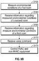
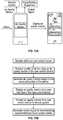
- Another implementationis a home control method that includes measuring, by a thermostat, environmental conditions in a first room of a building.
- the methodalso includes receiving, at the thermostat, information regarding measured environmental conditions from a first remote sensor unit in a second room of the building.
- the methodfurther includes controlling, by the thermostat, both heating, ventilation, and air condition (HVAC) equipment and non-HVAC equipment within the building based on the information received from the first remote sensor unit and the measured environmental conditions in the first room.
- HVACheating, ventilation, and air condition
- the first remote sensor unitcomprises a microphone configured to receive a voice command.
- the methodfurther includes receiving a voice command at the thermostat from the first remote sensor unit.
- the controlling both the HVAC equipment and the non-HVAC equipmentincludes controlling both the HVAC equipment and the non-HVAC equipment based on the voice command.
- the non-HVAC equipmentincludes a lighting system.
- the controlling both the HVAC equipment and the non-HVAC equipmentincludes operating the lighting system based on the voice command received from the first remote sensor unit.
- Some embodiments of the home control methodalso include receiving, at the thermostat, information associated with measured environmental conditions from a second remote sensor unit in a third room of the building.
- the controlling both the HVAC equipment and the non-HVAC equipmentincludes controlling both the HVAC equipment and the non-HVAC equipment based on a combination of the information associated with the measured environmental conditions received from the first remote sensor unit and the information associated with the measured environmental conditions received from the second remote sensor unit.
- the first remote sensor unitincludes an electrical outlet and a power relay configured to selectively provide power to the electrical outlet.
- the methodalso includes sending a command from the thermostat to the first remote sensor unit to operate the power relay based on the information received from the first remote sensor unit.
- the non-HVAC systemincludes at least one of a security system, a sprinkler system, or a home entertainment system.
- the home control systemincludes a user control device and a sensor unit.
- the user control deviceis located within a first room of a home and includes a first set of sensors configured to measure environmental conditions within the first room.
- the sensor unitis located within an electrical box recessed into a mounting surface in a second room of the home and includes a second set of sensors configured to measure environmental conditions within the second room.
- the user control deviceis configured to use measurement signals from the first and second sets of sensors to generate a control signal for home equipment that operate to affect the environmental conditions within the first and second rooms.
- the systemincludes a plurality of sensor units located within other electrical boxes in other rooms of the home.
- Each sensor unitmay include a set of sensors configured to measure environmental conditions within one of the other rooms.
- the user control devicemay be configured to use measurement signals from the plurality of sensor units to generate a control signal for home equipment that operate to affect the environmental conditions within the other rooms.
- the user control deviceis configured to receive temperature measurements from the plurality of sensor units indicating temperatures in multiple different rooms of the home, calculate an average temperature using the temperature measurements, and generate a control signal for home HVAC equipment based on the average temperature. In some embodiments, the user control device is configured to operate home HVAC equipment to maintain each of the temperatures in the multiple different rooms within a predetermined range of temperature values.
- the electrical boxis recessed into a wall of the second room and the sensor unit receives power from a power line extending through the wall.
- the electrical boxincludes a power outlet configured to receive an electric plug of a power-consuming device within the second room.
- the electrical boxincludes a power switch configured to control power to a power-consuming device within the second room.
- the sensor unitincludes a face plate covering the electrical box. The face plate may include an electronic display.
- the systemincludes a power relay located within the electrical box and operable to control power to a power-consuming device within the second room.
- the sensor unitis configured to operate the power relay based on input from the plurality of sensors.
- the sensor unitis configured to operate the power relay based on input from the user control device.
- the sensor unitincludes a microphone configured to receive voice commands from a user within the home and a power relay controller configured to operate the power relay in response to the microphone receiving a voice command.
- the sensor unitincludes a microphone configured to receive a voice command from a user within the second room of the home.
- the sensor unitmay be configured to send the voice command to the user control device.
- the user control devicemay be configured to operate the home equipment based on the voice command received from the sensor unit.
- the systemincludes another sensor unit located within another electrical box in another room of the home.
- the user control devicemay be configured to generate a control signal for the other sensor unit based on the voice command.
- the other sensor unitmay be configured to operate a power relay located within the other electrical box in response to receiving the control signal from the user control device.
- the sensor unit assemblyincludes an electrical box recessed into a mounting surface within a building zone, a power relay located within the electrical box and operable to control power to a power-consuming device within the building zone, and a sensor unit located within the electrical box.
- the sensor unitincludes a plurality of sensors and is configured to operate the power relay based on input from the plurality of sensors.
- the sensor unitincludes a data communications interface configured to communicate with a user control device located in a different building zone.
- the sensor unitmay be configured to operate the power relay based on input from the user control device.
- the sensor unitincludes a microphone configured to receive voice commands from a user within the building zone and a power relay controller configured to operate the power relay in response to the microphone receiving a voice command.
- the electrical boxincludes a power outlet configured to receive an electric plug of a power-consuming device within the building zone. In some embodiments, the electrical box includes a power switch configured to control power to a power-consuming device within the building zone. In some embodiments, the assembly includes a face plate covering the electrical box. The face plate may include an electronic display.
- the assemblyincludes a power relay located within the electrical box and operable to control power to a power-consuming device within the building zone.
- the sensor unitis configured to operate the power relay based on input from the plurality of sensors.
- the sensor unitincludes a microphone configured to receive voice commands from a user within the home and a power relay controller configured to operate the power relay in response to the microphone receiving a voice command.
- the user control deviceincludes a touch-sensitive display and a housing coupled to the touch-sensitive display.
- the housingis configured to attach to a mounting surface.
- the touch-sensitive displayis transparent or translucent such that the mounting surface is visible through the touch-sensitive display.
- the user control deviceincludes a touch-sensitive display and a housing coupled to the touch-sensitive display.
- the housingis configured to attach to a mounting surface.
- the user control devicefurther includes a processing circuit contained within the housing and configured to monitor and control the building equipment.
- the user control devicefurther includes a data communications interface contained within the housing and sensors located outside the housing. The sensors are configured to send measurements to the processing circuit via the data communications interface.
- the housingis located at least partially within a first electrical gang box within the mounting surface and the sensors are located at least partially within a second electrical gang box within the mounting surface.
- the sensorsare distributed throughout a building monitored and controlled by the user control device.
- the sensorsinclude a radon sensor.
- the user control deviceincludes a touch-sensitive display, a cellular transceiver configured to communicate with a cellular network, a WiFi transceiver configured to communicate with mobile devices, and a processing circuit coupled to the touch-sensitive display, the cellular transceiver, and the WiFi transceiver.
- the processing circuitis configured to monitor and control the building equipment and to bridge communications between the cellular network and the mobile devices via the cellular transceiver and the WiFi transceiver.
- the processing circuitis configured to operate the user control device as a WiFi hotspot to communicate directly with the mobile devices via the WiFi transceiver.
- the user control deviceincludes a housing configured to attach to a mounting surface, a microphone coupled to the housing, and a processing circuit contained within the housing.
- the processing circuitis configured to monitor and control the building equipment, monitor an input from the microphone for voice commands and control the building equipment in response to the voice commands.
- controlling the building equipmentincludes generating a control signal for the building equipment and providing the control to the building equipment.
- the control signalcauses the building equipment to activate, deactivate, operate at a different level, or change to a different an operating state.
- the user control deviceprovides an interface for environment control and at least one security device.
- the multi-function user control deviceincludes a display for indicating environmental parameters and images or video captured from the security device.
- the user control deviceincludes a processing circuit configured to monitor and control the building equipment, a data communications interface coupled to the processing circuit, and a sensors configured to send measurements to the processing circuit via the data communications interface.
- the user control deviceincludes a housing containing the processing circuit and the data communications interface.
- the sensorsmay be located outside the housing. In some embodiments, the sensors are distributed throughout a building monitored and controlled by the user control device. In some embodiments, the sensors are configured to communicate wirelessly with the processing circuit via the data communications interface.
- the sensorsinclude a humidity sensor located within a wall of the building.
- the sensorsinclude at least one of a smoke sensor, a fire sensor, a water leakage sensor, a humidity sensor, an air quality sensor, a vibration sensor, a temperature sensor, a light sensor, a camera, and a microphone.
- the user control deviceincludes an air quality sensor configured to measure a quality of airflow received at the user control device and a processing circuit coupled to the air quality sensor.
- the processing circuitis configured to generate air quality metrics based on the measured quality of the airflow and generate a control signal for the building equipment based on the air quality metrics.
- FIGS. 1 and 2are perspective view schematic drawings illustrating one or more physical features of a multi-function user control device, according to some embodiments.
- FIG. 3is a planar front view schematic drawing illustrating one or more physical features of a multi-function user control device, according to some embodiments.
- FIGS. 4 and 5are partial, perspective view schematic drawings illustrating one or more physical features of a bottom of a multi-function user control device, according to some embodiments.
- FIG. 6Ais a partial, perspective view schematic drawing illustrating one or more physical features of a top of a multi-function user control device, according to some embodiments.
- FIG. 6Bis a simplified, side front view schematic drawing illustrating one or more physical features of a multi-function user control device attached to a wall, according to some embodiments.
- FIG. 7Ais a schematic drawing illustrating the user control device as a connected smart hub in communication with various sensors, home automation devices, and building automation devices, according to some embodiments.
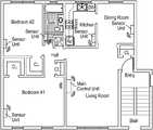
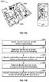
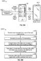
- FIG. 7Bis a floorplan of a home with a main control unit in one room and sensor units in other rooms, according to some embodiments.
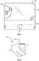
- FIG. 7Cis an exploded view drawing of a sensor unit assembly installed in an electrical gang box, according to some embodiments.
- FIG. 7Dis a planar, top view of the sensor unit assembly of FIG. 7C in an assembled state and embedded within a wall, according to some embodiments.
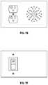
- FIG. 7Eis a drawing of a cover plate with holes which may be used in the sensor unit assembly of FIG. 7C , according to some embodiments.
- FIG. 7Fis a drawing of a cover plate with a light switch which may be used in the sensor unit assembly of FIG. 7C , according to some embodiments.
- FIG. 7Gis a drawing of a cover plate with a light switch and a display screen which may be used in the sensor unit assembly of FIG. 7C , according to some embodiments.
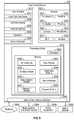
- FIG. 7His a block diagram illustrating the sensor unit of FIG. 7B in greater detail, according to some embodiments.
- FIG. 8is a block diagram illustrating the user control device in greater detail, according to some embodiments.
- FIG. 9Ais a block diagram illustrating a home module of the user control device in greater detail, according to some embodiments.
- FIG. 9Bis a flow diagram of a home control method, according to some embodiments.
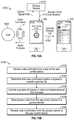
- FIGS. 10A-10Bare flow diagrams illustrating operations for monitoring and controlling connected equipment via a local interface of the user control device, according to some embodiments.
- FIGS. 11A-11Bare flow diagrams illustrating operations for monitoring and controlling connected equipment via a remote interface presented on a mobile device, according to some embodiments.
- FIGS. 12A-12Bare flow diagrams illustrating operations for receiving and handling voice commands at the user control device, according to some embodiments.
- FIGS. 13A-13Bare flow diagrams illustrating operations for measuring and reporting air quality metrics and adjusting system operation based on the air quality metrics, according to some embodiments.
- FIGS. 14A-14Bare flow diagrams illustrating operations for performing diagnostics based on performance data received from home/building equipment and automatically scheduling service or ordering replacement parts based on the diagnostics, according to some embodiments.
- FIGS. 15A-15Bare flow diagrams illustrating operations for using utility rate information, weather forecasts, and performance information from HVAC equipment to forecast an energy bill and adjust system operation based on the energy bill forecast, according to some embodiments.
- FIGS. 16A-16Bare flow diagrams illustrating operations for comparing energy consumption data from local HVAC equipment to energy consumption data from other homes/buildings and generating energy consumption analytics based on the comparison, according to some embodiments.
- FIGS. 17A-17Bare flow diagrams illustrating operations determining the occupancy of a building and adjusting system operation as a user moves between rooms or zones of the building, according to some embodiments.
- FIGS. 18A-18Bare flow diagrams illustrating operations for receiving weather forecasts from a weather service, displaying the weather forecasts on the user control device, and adjusting system operation based on the weather forecasts, according to some embodiments.
- FIGS. 19A-19Bare flow diagrams illustrating operations for receiving voice commands from a user and updating a grocery list based on the voice commands, according to some embodiments.
- FIGS. 20A-20Bare flow diagrams illustrating operations for receiving status information from home/building equipment and sending an alert to a mobile device if the status information does not match a predetermined system status, according to some embodiments.
- FIGS. 21A-21Billustrate a process for using calendar information to automatically detect prolonged periods of no occupancy and adjust system operation during the periods of no occupancy, according to some embodiments.
- FIGS. 22A-22Bare flow diagrams illustrating operations for bridging communications between a cellular network, an Ethernet network, and a WiFi network via the user control device, according to some embodiments.
- FIG. 23is a perspective view of a building equipped with a building management system (BMS) and HVAC system, according to some embodiments.
- BMSbuilding management system
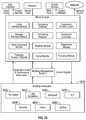
- FIG. 24is a block diagram illustrating the BMS of FIG. 23 in greater detail, according to some embodiments.
- FIG. 25is a block diagram illustrating the building module of the user control device in greater detail, according to some embodiments.
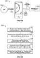
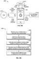
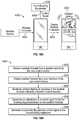
- FIG. 26Ais an illustration of the user control device detecting occupancy, according to some embodiments.
- FIG. 26Bis a flow diagram illustrating operations shown in FIG. 26A , according to some embodiments.
- FIG. 27Ais a flow diagram illustrating operations in which the user control device uses schedule data to determine occupancy, according to some embodiments.
- FIG. 27Bis a schematic drawing of various applications and their user interfaces through which the user control device may obtain schedule data and determine occupancy, according to some embodiments.
- FIG. 27Cis a drawing of a scheduling screen the user control device, through which the process of handling multiple occupancy homes is shown, according to some embodiments.
- FIG. 28is a drawing of operations in which the user control device adjusts the temperature of a home to a user's preferences prior to her arrival at home, according to some embodiments.
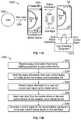
- FIG. 29is a drawing of operations in which the user control device adjusts compressor staging using occupancy, according to some embodiments.
- FIG. 30is a flow diagram illustrating the flow of information between the user control device, HVAC equipment, a network, and network-connected devices and services, according to some embodiments.
- FIG. 31Ais a drawing of operations through which the user control device may interact with a user to affect the energy consumption and energy bill of a building space, according to some embodiments.
- FIG. 31Bis a drawing of user interfaces through which the user control device may display reports which compare and contrast a user's energy consumption and behavior with other similar systems, according to some embodiments.
- FIG. 31Cis a flow diagram of operations for testing new settings automatically, according to some embodiments.
- FIG. 31Dis a drawing of operations in which the user control device alerts users that it is unable to reach a set point, according to some embodiments.
- FIG. 32is a drawing of analytics which may be provided by the user control device, according to some embodiments.
- the user control devicemay be implemented as a smart hub and may be connected to any of a variety of sensors, controllable systems, and devices to form a home control system.
- the user control devicemay be connected to a home automation system, a building automation system, an HVAC system, a lighting system, a security system, an electrical system, a sprinkler system, a home entertainment system, and/or any other type of system that can be monitored or controlled via a user device.
- the user control devicemay be implemented in any of a variety of environments (e.g., a home, a building, a classroom, a hotel, a healthcare facility, a vehicle, etc.) and used to monitor, control, and/or facilitate user interaction with controllable systems or devices in such environments.
- environmentse.g., a home, a building, a classroom, a hotel, a healthcare facility, a vehicle, etc.
- the user control devicemay be installed in a home or building (e.g., mounted on a wall) and may function as a thermostat for the home or building.
- the user control devicefunctions as a thermostat and includes a central control hub that communicates with remote sensors, HVAC equipment, and non-HVAC equipment.
- the user control deviceincludes a processing circuit that monitors and controls both the HVAC and non-HVAC equipment.
- a thermostatis an ideal device for use as a central control hub for controlling non-HVAC equipment due, at least in part, to the already existing need for a thermostat in each home to control HVAC components and to the generally central location of thermostats within the home.
- the use of a thermostat as a central control huballows for HVAC and additional non-HVAC home automation features to be consolidated into a single device and home control system, thus simplifying the control of systems and devices within the home.
- the user control devicee.g., the thermostat
- the remote sensorsinclude electronic components that monitor one or more environmental or other conditions and may be distributed throughout various rooms of a building. As an example, the sensors can measure temperature, humidity, an amount of ambient light, damper locations of ductwork, occupancy of a room, position of window blinds, etc.
- the user control devicecan operate non-HVAC equipment to control the environment of a room or building.
- the user control devicecan open or close blinds during the day to control the amount of sunlight and, therefore, heat let in through windows.
- the user control devicecommunicates with a microphone to receive voice commands.
- the voice commandcan be received by the user control device and, based on the command, the user control device can operate the HVAC or non-HVAC equipment.
- a voice commandcan be used to cause the blinds to open, the lights to turn on, the thermostat to change a setpoint, etc.
- the user control deviceis in communication with an occupancy sensor.
- the occupancy sensorcan detect whether a room is occupied by a human, a dog, etc.
- the occupancy sensorcan include a microphone, a sonar sensor, an infrared imaging device, a motion detector, a proximity sensor, an ambient light sensor, a vibration sensor, etc.
- the user control devicecan control the HVAC and/or non-HVAC equipment based on which rooms are occupied. For example, a storage room of a house can normally be maintained at a temperature different from the rest of the house (e.g., higher in the summer or colder in the winter). If an occupancy sensor detects that the storage room is occupied, the user control device can increase or decrease the temperature of the room via HVAC equipment, open blinds, turn on lights, etc., to make the room more comfortable for the occupants.
- the user control devicecan be in communication with remote sensors that are distributed throughout a building.
- a housecan include several rooms that each have a temperature sensor that detects the temperature in the room and one or more HVAC ducts that blow air into the room.
- Each roomcan be associated with one or more dampers, valves, etc., to control the amount of air blown into the respective room by the HVAC equipment.
- Each damper (or valve, etc.)can be controlled by the user control device.
- the user control devicecan monitor the temperature of each room.
- Each roomcan have an independent set point.
- the user control devicecan adjust the position of the dampers to control the temperature of each room to maintain the respective setpoint temperatures.
- the user control devicecan be equipped with one or more of a variety of sensors (e.g., temperature, humidity, air quality, proximity, light, vibration, motion, optical, audio, occupancy, power, security, etc.) configured to sense a variable state or condition of the environment in which the user control device is installed.
- the user control devicemay include a variety of user interface devices (e.g., a touch-sensitive panel, an electronic display, speakers, haptic feedback, ambient lighting, etc.) configured to facilitate user interaction with the user control device.
- the user control devicemay include a data communications interface configured to facilitate communications between the user control device and a building automation system, a home automation system, HVAC equipment, mobile devices (e.g., via WiFi, Bluetooth, NFC, LTE, LAA LTE, etc.), a communications network (e.g., a LAN, WAN, 802.11, the Internet, a cellular network, etc.), and/or any other systems or devices to which the user control device may be connected.
- a data communications interfaceconfigured to facilitate communications between the user control device and a building automation system, a home automation system, HVAC equipment, mobile devices (e.g., via WiFi, Bluetooth, NFC, LTE, LAA LTE, etc.), a communications network (e.g., a LAN, WAN, 802.11, the Internet, a cellular network, etc.), and/or any other systems or devices to which the user control device may be connected.
- the user control devicemay be configured to function as a connected smart hub and may provide a variety of features not found in traditional thermostats.
- the user control devicemay be configured to receive voice commands from a user and control connected equipment in response to the voice commands.
- the user control devicemay be configured to connect to mobile devices (e.g., a user's phone, tablet, laptop, etc.) to allow remote monitoring and control of connected systems.
- the user control devicemay be configured to detect the occupancy of a room or space in which the user control device is installed and may perform a variety of occupancy-based control processes.
- the user control devicemay monitor the performance of connected equipment (e.g., HVAC equipment) and may perform diagnostics based on data received from the HVAC equipment.
- connected equipmente.g., HVAC equipment
- the user control devicemay receive weather forecasts from a weather service and utility rate information from a utility provider.
- the user control devicemay use the weather forecasts in conjunction with the utility rate information to optimize (e.g., minimize) the energy consumption of the home or building.
- the user control devicegenerates a utility bill forecast and recommends set point modifications to reduce energy consumption or energy cost.
- the user control devicereceives energy consumption information for other homes/buildings from a remote system and compares the energy consumption of connected HVAC equipment to the energy consumption of the other homes/buildings.
- the user control devicereceives weather information from a weather service.
- the user control devicemay display directions to an emergency area of the building (e.g., a basement) in response to the weather information indicating dangerous weather conditions.
- a user control devicecan be used to automate a home, office, commercial building, etc.
- a buildingcan be retrofitted to include various sensor and control devices to automate the building.
- a user control devicecan be installed to control the temperature of multiple rooms of a house.
- Wireless temperature sensorscan be installed in each room to be controlled and can communicate the temperature of the respective room to the user control device.
- Damperscan be installed in the existing ductwork of the house to independently control the airflow to each room.
- the user control devicecan wirelessly communicate with the dampers to maintain each room at a respective temperature setpoint.
- the user control devicecan replace an existing thermostat to control the existing HVAC equipment.
- the usercan automate some or all of the rooms of a building and can include various sensors or equipment. Some users may include in their home automation system occupancy detection, and some may include automatic window blind control. In some instances, a user control device can be adapted to virtually any level of automation that a user desires.
- the user control device 100can be a thermostat that includes a central control hub functionality.
- the user control device 100can be communicatively coupled to HVAC equipment to control the ambient atmosphere (e.g., temperature, humidity, etc.) of one or more rooms.
- the user control devicecan also be communicatively coupled to non-HVAC equipment or systems such as, for example, lighting systems, blind control systems, security systems, entertainment devices or systems, refrigeration systems, etc.
- the user control device 100can further be communicatively coupled to one or more remote sensors, remote servers, or other information sources that may provide data for use by the user control device 100 to automate various systems or devices within a building.
- the user control device 100can be configured to communicate information to a user (e.g., status of equipment, temperature of a room, etc.) and to receive inputs from a user to change settings, set up new equipment, etc.
- User control device 100can be mounted on a wall or other suitable mounting location (e.g., a vertical wall within a home or building, a ceiling, a floor, a surface of an object within a building space, a ledge, a dashboard, furniture, a vehicle seat or other vehicle surface, etc.).
- the user control device 100can be mounted in a location that allows the user control device 100 to communicate wirelessly with one or more remote sensors or devices.
- user control device 100is mounted on a wall in front of an electrical gang box and receives electrical connections and/or data connections through the gang box. In other embodiments, user control device 100 is attached to a wall without requiring a gang box.
- User control device 100is shown to include a touch-sensitive display 102 , a housing 104 , a sensor window 106 , and an ambient lighting frame 108 .
- the multi-function user control device 100is detachable from the wall and can be carried by a user.
- Touch-sensitive display 102may be a touchscreen or other type of electronic display configured to present information to a user in a visual format (e.g., as text, graphics, etc.) and receive input from a user (e.g., via a touch-sensitive panel).
- the touch-sensitive display 102can be used to display status information (e.g., current temperature, heating/cooling settings, errors, etc.) and can be used to set up communications between the user control device 100 and remote sensors or equipment.
- touch-sensitive display 102may include a touch-sensitive panel layered on top of an electronic visual display.
- a usercan provide input to user control device 100 through simple or multi-touch gestures by touching display 102 with one or more fingers and/or a stylus/pen.
- Touch-sensitive display 102can use any of a variety of touch-sensing technologies such as resistive sensing, surface acoustic wave, capacitive sensing (e.g., surface capacitance, projected capacitance, mutual capacitance, self-capacitance, etc.), infrared grid, infrared acrylic projection, optical imaging, dispersive signal technology, acoustic pulse recognition, or other touch-sensitive technologies known in the art. Many of these technologies allow for multi-touch responsiveness of display 102 allowing registration of touch in two or even more locations at once.
- multi-touch responsivenesscan be used to conveniently allow a user to monitor the status of remote sensors. For example, a user can use a two-finger swiping motion and the display 102 can, in response, display the current temperature of another room (e.g., sensed by a remote sensor).
- touch-sensitive display 102includes a transparent or translucent display screen.
- the display screenmay use any of a variety of display technologies such as light emitting diode (LED), organic light-emitting diode (OLED), liquid-crystal display (LCD), organic light-emitting transistor (OLET), surface-conduction electron-emitter display (SED), field emission display (FED), digital light processing (DLP), liquid crystal on silicon (LCoC), or any other display technologies known in the art.
- Touch-sensitive display 102may be configured to present visual media (e.g., text, graphics, etc.) without requiring a backlight.
- touch-sensitive display 102may be transparent or translucent to allow the surface behind display 102 to be seen through display 102 . For example, if user control device 100 is mounted on a wall, the wall may be visible through display 102 . This allows user control device 100 to blend in to the surface upon which user control device 100 is mounted.
- Touch-sensitive display 102provides a variety of information to a user either when prompted by the user, or when pushed to the user, without prompting, by another system (e.g., a security system, a weather monitoring system, etc.) or remote sensors (e.g., a smoke detector, a fire detector, a malfunctioning sensor, etc.).
- Touch-sensitive display 102may have a generally vertical orientation (as shown in FIGS. 1-6B ) or a generally horizontal orientation. The size of display 102 may be varied depending on the space in which the user control device 100 is installed and the functionality desired for user control device 100 .
- Housing 104may be attached to touch-sensitive display 102 along one or more edges or surfaces of display 102 .
- Housing 104provides a structure to mount user control device 100 to a wall or other surface.
- Housing 104may be formed from a variety of materials (e.g., polymers, metals, composite materials, laminates, etc.) and may have a variety of different appearances or finishes.
- touch sensitive display 102is detachable from housing 104 for use in a portable fashion.
- Housing 104can include a charging circuit for the touch sensitive display.
- housing 104contains one or more sensors.
- housing 104may contain a temperature sensor, a humidity sensor, a motion sensor, an air quality sensor (e.g., carbon monoxide, carbon dioxide, allergens, smoke, etc.), a proximity sensor (e.g., NFC, RFID, Bluetooth, etc.), a camera, a microphone, a light sensor, a vibration sensor, or any other type of sensor configured to measure a variable state or condition of the environment in which user control device 100 is installed.
- the proximity sensoris used to turn on display 102 when the user is close to user control device 100 and turn off display 102 when the user is not close to user control device 100 , leading to less power usage and longer screen life.
- Some internal sensorssuch as a camera, light sensor, or optical sensor may be configured to monitor the room or space through a sensor window 106 (shown in FIG. 5 ).
- Other internal sensorssuch as a temperature sensor, humidity sensor, and air quality sensor may receive airflow from the room or space via holes 110 in housing 104 (shown in FIG. 4 ).
- the sensorsmay be located external to housing 104 and may provide input to user control device 100 via a data communications link.
- one or more sensorsmay be installed in a gang box behind user control device 100 , installed a separate gang box mounted within the same wall to which user control device 100 is mounted, or otherwise located throughout the room or space monitored or controlled by user control device 100 (e.g., in a wall, in a ceiling panel, in an open volume of the room or space, in a duct providing airflow to the room or space or receiving airflow from the room or space, etc.).
- user control device 100is installed in front of one gang box and the sensors are installed in a separate gang box.
- a humidity sensormay be positioned in a wall and configured to measure the humidity within the wall (e.g., to detect water leakage or burst pipes).
- Housing 104may contain a variety of electronic components configured to perform control functions (e.g., a circuit board, memory, a processor, etc.), facilitate communications with remote sensors or equipment (e.g., a WiFi transceiver, a cellular transceiver, a communications interface, etc.), and provide a visual display via display 102 (e.g., a video card or module, etc.).
- all of the electronics other than touch-sensitive display 102are contained within housing 104 .
- the sensorsare located within housing 104 and the remaining electronics are located elsewhere (e.g., in a circuit board perpendicular display 102 inside of the wall, in a gang box, part of a separate system in communication with user control device 100 ).
- the circuit boardis perpendicular to touch-sensitive display 102 and disposed in its own housing or bracket. The circuit board may be connected to the remaining electronics within housing 104 or elsewhere via a wiring harness or connector.
- housing 104is a modular housing configured to house any of a variety of interchangeable modules or components.
- housing 104may include any of the features of the modular thermostat described in U.S. Provisional Application No. 62/260,141 filed Nov. 25, 2015, the entirety of which is incorporated by reference herein.
- the modular features of housing 104provide a user with an unparalleled ability to upgrade, repair, or replace individual components of user control device 100 without replacing the entire device 100 .
- user control device 100includes a plurality of modular boards, each of which provides user control device 100 with different capabilities.
- user control device 100may include a motherboard, a networking board, an occupancy detection board, a humidity board, a near field communications (NFC) board, a temperature board, an energy harvesting board, a battery board, and/or any other type of modular board.
- One or more boardscan be interchanged such that the user control device 100 is compatible with various sensors and/or equipment of a system.
- a usermay implement a building automation system that includes an HVAC system, automatic window blinds, automatic lighting controls, and entertainment devices (e.g., music players or television).
- the boards of the user control device 100can be selected to be compatible and communicative with the sensors, motors, actuators, etc., of the HVAC system as well as the window blinds, the lighting, and the entertainment devices.
- the humidity boardmay be configured to measure the humidity of the room or space and may include an integrated humidity sensor.
- the NFC boardmay be configured to provide communications between user control device 100 and an external device through NFC.
- the temperature boardmay be configured to measure the temperature of the room or space and may include an integrated temperature sensor.
- the energy harvesting boardmay be configured to interact with an energy harvesting apparatus.
- the networking boardmay be configured to allow user control device 100 to communicate with other devices through the internet, Bluetooth, WiFi, or other suitable communications platform.
- the occupancy detection boardmay be configured to monitor the occupancy of the room or space (e.g., determine the number of people in the space) and adjust the control signals provided by user control device 100 accordingly.
- the battery boardmay include a battery configured to provide power to user control device 100 as a primary means of power or as backup power in the event of a power outage.
- User control device 100may be used with any combination of the listed modular boards or any other modular board to provide additional functionality.
- user control device 100may include only the temperature board and the networking board in some embodiments, whereas user control device may include an additional NFC board in other embodiments.
- the modular boardsmay each be independently installed and/or upgraded to provide user control device with any combination of desired functionality.
- user control device 100includes an ambient lighting frame 108 .
- Ambient lighting frame 108may be configured to emit ambient light from an edge or perimeter of display 102 .
- ambient lighting frame 108may be positioned along the sides and top of display 102 (as shown in FIGS. 1-3 ) and/or along any other surface or edge of display 102 .
- Ambient lighting frame 108may be configured to emit ambient lighting toward the wall or surface upon which user control device 100 is mounted.
- FIG. 6Bshows user control device 100 mounted to a wall 112 .
- Display 102may emit light in a direction substantially perpendicular to the front surface of display 102 in a direction away from wall 112 (i.e., to the left in FIG. 6B ).
- Ambient lighting frame 108may emit ambient light in an opposite direction toward wall 112 (i.e., toward the right in FIG. 6B ) and/or in a direction substantially coplanar with display 102 (i.e., upward in FIG. 6B ).
- ambient lighting frame 108allows user control device 100 to illuminate wall 112 with ambient lighting from frame 108 in addition to presenting visual media (e.g., graphics, text, etc.) via display 102 .
- user control device 100may emit yellow ambient lighting toward wall 112 to indicate that severe weather is approaching.
- a variety of colors of ambient lightmay be emitted from ambient lighting frame 108 to indicate various conditions (e.g., yellow for alerts or warnings, red for emergencies, etc.).
- user control device 100includes other forms of ambient lighting (e.g., LEDs integrated with housing 104 ) in addition to or in place of ambient lighting frame 108 .
- the amount of light emitted by the ambient lighting frame 108corresponds to a level of ambient light in the room in which the user control device 100 is located.
- the user control device 100remotely controls the lighting of the room based on user input.
- the light emitted by the ambient lighting frame 108can be increased to be commensurate with the lights of the room turning on.
- the light emitted by the ambient lighting frame 108can be reduced or turned off.
- the amount or type of light emitted by the ambient lighting frame 108can correspond to the status or measurements of one or more remote sensors or equipment.
- user control device 100is shown as a connected smart control hub or private area network (PAN), according to some embodiments.
- User control device 100may include a variety of sensors which may be integrated into the user control device 100 or may be remote from the user control device 100 .
- the sensorsmay be configured to communicate with a variety of external systems or devices.
- user control device 100may include a temperature sensor, a sound sensor, a humidity sensor, a light sensor, a proximity sensor, a carbon dioxide sensor, an occupancy sensor, or any of a variety of other sensors.
- user control device 100may receive input from external sensors configured to measure such variables.
- User control device 100may communicate with a remote camera, a shade control system, a leak detection system, an HVAC system, or any of a variety of other external systems or devices which may be used in a home automation system or a building automation system.
- User control device 100may provide a variety of monitoring and control interfaces to allow a user to control all of the systems and devices connected to user control device 100 . Exemplary user interfaces and features of user control device 100 are described in greater detail below.
- FIG. 7Ba floorplan of a home is shown.
- the homeis shown to include several different zones (e.g., rooms or areas) such as a living room, a first bedroom, a second bedroom, a bathroom, a kitchen, and a dining room.
- a main control unitmay be installed in one of the rooms or zones.
- FIG. 7Bshows a main control unit installed in the living room.
- the main control unitis the same or similar to user control device 100 , as previously described.
- the main control unitmay serve as a central control hub for monitoring environmental conditions and controlling various devices throughout the home.
- Sensor unitsmay be installed in various rooms or zones in the home.
- FIG. 7Bshows a sensor unit installed in each of the bedrooms, the bathroom, the kitchen, and the dining room.
- the sensor unitsmay be configured to measure environmental conditions within each room or zone and to receive user input (e.g., voice commands via a microphone).
- each sensor unitmay include a plurality of sensors (e.g., a temperature sensor, a humidity sensor, a smoke detector, a light sensor, a camera, a motion sensor etc.) configured to measure variables such as temperature, humidity, light, etc. in the room or zone in which the sensor unit is installed.
- the sensor unitsmay communicate (e.g., wirelessly or via a wired communications link) with the main control unit and/or with each other.
- sensorssuch as low power door sensors, can communicate with repeaters disposed in the gang boxes or other locations using a low power overhead protocol. The repeaters can provide wired or wireless communication to the main control unit.
- each sensor unitis installed within an electrical gang box, as shown in FIGS. 7C-7D .
- the electrical gang boxmay be a single gang box, a double gang box, triple gang box, etc.
- the electrical gang boxmay be recessed into the wall and may be covered by a cover plate.
- the gang boxis a power outlet gang box and may be covered by a power outlet cover plate (as shown in FIG. 7C ).
- the gang boxmay be a power switch gang box and may be covered by a power switch cover plate (as shown in FIG. 7F ).
- the switchcan include a sensor.
- the cover plateincludes holes or an optical window to allow the sensor unit to better sense conditions within the room or zone in which the sensor unit is installed (as shown in FIG. 7E ).
- the cover plateincludes the sensor.
- the cover plateincludes a switch on one half of the cover plate and a display screen (e.g., an e-ink display) on the other half of the cover plate (as shown in FIG. 7G ). This allows each sensor unit to provide an output via the display screen in addition to sensing conditions within the room or zone.
- each sensor unitincludes a microphone configured to detect voice commands from a user.
- thisallows a user to control systems and devices within the home from any room without requiring the user to interact directly with the main control unit.
- a user in the dining roommay provide the voice command “Hey GLASS, turn off the lights in the bathroom.”
- the voice commandmay be detected by the sensor unit in the dining room and transmitted to the main control unit.
- the sensor unitincludes voice command module that captures audio data associated with a spoken phrase and provides the audio data to the user control device where the audio data is interpreted to determine a command.
- the main control unitmay act based on the voice command by causing the lights in the bathroom to turn off.
- each sensor unitincludes a speaker configured to provide audio feedback to a user upon receiving voice commands.
- each sensor unitincludes an integrated controller or other electronics configured to control conditions within the room in which the sensor unit is installed.
- each sensor unitmay be connected to a power relay for the room or zone in which the sensor unit is installed.
- the power relaymay be installed within the electrical gang box along with the sensor unit (as shown in FIGS. 7C-7D ).
- Each sensor unitmay be configured to operate the power relay to activate or deactivate various power outlets, appliances, or other devices in the room.
- the sensor unitsare configured to act upon voice commands without requiring the main control unit.
- a sensor unitmay operate a connected power relay (e.g., a power relay installed in the electrical gang box with the sensor unit) in response to sensing a voice command at a microphone of the sensor unit.
- each sensor unitmay be installed in an electrical gang box along with a power relay.
- the gang boxmay be recessed into the wall and connected to a power line embedded in the wall.
- the power linemay connect to both the power relay and the sensor unit.
- the power relaymay be connected between the power supply line and the power outlet.
- the sensor unit within the electrical gang boxmay be configured to operate the power relay to control the power supply to the connected power outlet. For example, the sensor unit can activate the connected power relay to provide power to the connected power outlet, and deactivate the connected power relay to cut power to the connected power outlet.
- the sensor unitis integrated with an electrical switch or outlet provided in the gang box, thereby providing an easy retrofit for an existing outlet or switch.
- the sensor unitincludes a battery or capacitive energy storage device that is recharged via power conductors in the gang box. In some embodiments, the battery or capacitive energy storage provides 72 hours of sensor operation after power is no longer supplied by the power conductors in the gang box.
- the sensor unitsmay operate the power relays in response to voice commands received at the microphones of the sensor units (e.g., “Hey GLASS, turn off the lights in this room”) and/or in response to control signals from the main control unit.
- the sensor unitsoperate the power relays based on input signals from various sensors integrated with the sensor units.
- each sensor unitmay include an occupancy sensor configured to detect occupancy within the room or zone in which the sensor unit is installed. If the room remains unoccupied for a predetermined time period, the sensor unit may deactivate the power relay, causing the lights in the room to turn off.
- the main control unituses input from multiple different sensor units to make control decisions.
- the main control unitcontrols HVAC and non-HVAC equipment based on a combination of information received from multiple sensor units. For example, the main control unit may receive temperature inputs from the various sensor units indicating the temperature of each room. The main control unit may use the sensor inputs to determine an average temperature for the home.
- the main control unitoperates the home HVAC system to control the average temperature to a temperature set point or within a temperature range.
- the HVAC systemis controlled on a zone by zone basis and average temperature from a number of sensors in each zone is used to control each zone.
- HVAC systemis controlled using a maximum sensed temperature among a group of sensed temperatures or a minimum sensed temperature among a group of sensed temperatures.
- temperature readingsare weighted according to location on a room by room basis with more heavily used rooms having a greater weight for an average calculation.
- the temperature readingsare weighted based upon location and time (e.g., bedrooms having a greater weight during sleeping hours and kitchen and living areas having a greater weight during waking hours.
- the main control unitoperates the home HVAC system to ensure that each of the individual temperatures (i.e., the temperatures measured by the various sensor units) is within a comfortable temperature range.
- the main control unituses input from multiple different sensor units to determine the room in which an occupant is located. For example, the main control unit may use signals from motion sensors or occupancy sensors of the sensor units to determine which rooms are occupied. In some embodiments, the main control unit processes audio inputs from the microphones of the various sensor units to determine which of the sensor units records the loudest volume. The main control unit may determine that the room with the loudest detected volume is the room in which an occupant is located.
- the main control unituses input from multiple different sensor units to determine a safe evacuation route out of the home.
- each sensor unitmay include sensors configured to detect a fire (e.g., smoke detectors, thermal cameras, etc.) in the room in which the sensor unit is installed. If a fire is detected in the living room, the main control unit may determine that any evacuation route out of the home should avoid the living room.
- the main control unitmay be configured to cause the sensor units in each room to display a safe evacuation route (e.g., via the display screens of the sensor units) which avoids the room with the fire.
- the main control unit and/or sensor unitsannounce the evacuation route audibly or display the evacuation routes on a map based upon the locations of the sensed hazards.
- the sensor unitis shown to include a variety of sensors including, for example, a temperature sensor, a humidity sensor, a microphone, a light sensor, and an occupancy sensor.
- sensorsincluding, for example, a temperature sensor, a humidity sensor, a microphone, a light sensor, and an occupancy sensor.
- the particular sensors shown in FIG. 7Hare not limiting and that the sensor unit may include any type of sensor in addition to those specifically shown.
- the sensor unitmay include an air quality sensor, an oxygen sensor, a carbon monoxide sensor, a smoke sensor, a camera, a water leakage sensor, an accelerometer, an infrared sensor, a pressure sensor, a motion sensor, and/or any other type of sensor which may be used to sense a variable state or condition within a room or zone of a home or building.
- the sensor unitis shown to include a display.
- the displayis an electronic ink display (e.g., electronic paper).
- the displaymay use any other display technology such as light emitting diode (LED), organic light-emitting diode (OLED), liquid-crystal display (LCD), organic light-emitting transistor (OLET), surface-conduction electron-emitter display (SED), field emission display (FED), digital light processing (DLP), liquid crystal on silicon (LCoC), or any other display technologies known in the art.
- the displayis a touch-sensitive display (e.g., a touchscreen).
- the sensor unitincludes a speaker configured to provide audio output to a user.
- the sensor unitis shown to include a communications interface and a processing circuit.
- the communications interface of the sensor unitis configured to communicate data with a communications interface of a main control unit.
- the communications interfacemay include wired or wireless interfaces (e.g., jacks, antennas, transmitters, receivers, transceivers, wire terminals, etc.) for conducting data communications with various systems, devices, or networks.
- the communications interfacemay include an Ethernet card and port for sending and receiving data via an Ethernet-based communications network and/or a WiFi transceiver for communicating via a wireless communications network.
- the communications interfacemay be configured to communicate via local area networks or wide area networks (e.g., the Internet, a building WAN, etc.) and may use a variety of communications protocols (e.g., BACnet, IP, LON, Zigbee, Bluetooth, etc.).
- the sensor unitmay use the communications interface to communicate with the main control unit, other sensor units, mobile devices within the home, a home network, or other systems or devices.
- the processing circuitis shown to include a processor and memory.
- the processormay be a general purpose or specific purpose processor, an application specific integrated circuit (ASIC), one or more field programmable gate arrays (FPGAs), a group of processing components, or other suitable processing components.
- the processormay be configured to execute computer code or instructions stored in memory or received from other computer readable media (e.g., CDROM, network storage, a remote server, etc.).
- the memorymay include one or more devices (e.g., memory units, memory devices, storage devices, etc.) for storing data and/or computer code for completing and/or facilitating the various processes described in the present disclosure.
- the memorymay include random access memory (RAM), read-only memory (ROM), hard drive storage, temporary storage, non-volatile memory, flash memory, optical memory, or any other suitable memory for storing software objects and/or computer instructions.
- RAMrandom access memory
- ROMread-only memory
- the memorymay include database components, object code components, script components, or any other type of information structure for supporting the various activities and information structures described in the present disclosure.
- the memorymay be communicably connected to the processor via the processing circuit and may include computer code for executing (e.g., by the processor) one or more processes described herein.
- the sensor unitis shown to include a power relay controller.
- the power relay controllermay be configured to operate a power relay which controls the power supply to a power outlet, room lighting, or other powered systems or devices.
- the power relay controllermay operate the power relay based on voice commands detected at the microphone of the sensor unit, control signals received from the main control unit via the communications interface, an occupancy signal from the occupancy sensor, a predetermined power schedule stored in memory, and/or any other criteria which may be used to control power to a connected system or device.
- the power relayis installed in the same electrical gang box as the sensor unit, as shown in FIGS. 7C-7D .
- thisallows each sensor unit to operate a local power relay without requiring input from the main control unit.
- User control device 100is shown to include a variety of user interface devices 3010 and sensors 3020 .
- User interface devices 3010may be configured to receive input from a user and provide output to a user in various forms.
- user interface devices 3010are shown to include a touch-sensitive panel 3001 , an electronic display 3002 , ambient lighting 3003 , speakers 3004 , and haptic feedback 3005 .
- user interface devices 3010include a microphone configured to receive voice commands from a user, a keyboard or buttons, switches, dials, or any other user-operable input devices.
- user interface devices 3010may include any type of device configured to receive input from a user and/or provide an output to a user in any of a variety of forms (e.g., touch, text, video, graphics, audio, vibration, etc.).
- Sensors 3020may be configured to measure a variable state or condition of the environment in which user control device 100 is installed.
- sensors 3020are shown to include a temperature sensor 3021 , a humidity sensor 3022 , an air quality sensor 3023 , a proximity sensor 3024 , a camera 3025 , a microphone 3026 , a light sensor 3027 , and a vibration sensor 3028 .
- Air quality sensor 3023may be configured to measure any of a variety of air quality variables such as oxygen level, carbon dioxide level, carbon monoxide level, allergens, pollutants, smoke, etc.
- Proximity sensor 3024may include one or more sensors configured to detect the presence of people or devices proximate to user control device 100 .
- proximity sensor 3024may include a near-field communications (NFC) sensor, a radio frequency identification (RFID) sensor, a Bluetooth sensor, a capacitive proximity sensor, a biometric sensor, or any other sensor configured to detect the presence of a person or device.
- Camera 3025may include a visible light camera, a motion detector camera, an infrared camera, an ultraviolet camera, an optical sensor, or any other type of camera.
- Light sensor 3027may be configured to measure ambient light levels.
- Vibration sensor 3028may be configured to measure vibrations from earthquakes or other seismic activity at the location of user control device 100 .
- Data communications interface 3060may include wired or wireless interfaces (e.g., jacks, antennas, transmitters, receivers, transceivers, wire terminals, etc.) for conducting data communications with various systems, devices, or networks.
- data communications interface 3060may include an Ethernet card and port for sending and receiving data via an Ethernet-based communications network and/or a WiFi transceiver for communicating via a wireless communications network.
- Data communications interface 3060may be configured to communicate via local area networks or wide area networks (e.g., the Internet, a building WAN, etc.) and may use a variety of communications protocols (e.g., BACnet, IP, LON, etc.).
- Data communications interface 3060may include a network interface configured to facilitate electronic data communications between user control device 100 and various external systems or devices (e.g., a communications network 3062 , a building automation system (BAS) or home automation system 3064 , HVAC equipment 3066 , mobile devices 3068 , etc.).
- user control device 100may receive information from building/home automation system 3064 or HVAC equipment 3066 indicating one or more measured states of the controlled building (e.g., temperature, humidity, electric loads, etc.) and one or more states of the HVAC equipment 3066 (e.g., equipment status, power consumption, equipment availability, etc.).
- Data communications interface 3060may receive inputs from building/home automation system 3064 or HVAC equipment 3066 and may provide operating parameters (e.g., on/off decisions, set points, etc.) to building/home automation system 3064 or HVAC equipment 3066 .
- the operating parametersmay cause building/home automation system 3064 to activate, deactivate, or adjust a set point for various types of home equipment or building equipment in communication with user control device 100 .
- Processing circuit 3030is shown to include a processor 3032 and memory 3034 .
- Processor 3032may be a general purpose or specific purpose processor, an application specific integrated circuit (ASIC), one or more field programmable gate arrays (FPGAs), a group of processing components, or other suitable processing components.
- ASICapplication specific integrated circuit
- FPGAsfield programmable gate arrays
- Processor 3032may be configured to execute computer code or instructions stored in memory 3034 or received from other computer readable media (e.g., CDROM, network storage, a remote server, etc.).
- Memory 3034may include one or more devices (e.g., memory units, memory devices, storage devices, etc.) for storing data and/or computer code for completing and/or facilitating the various processes described in the present disclosure.
- Memory 3034may include random access memory (RAM), read-only memory (ROM), hard drive storage, temporary storage, non-volatile memory, flash memory, optical memory, or any other suitable memory for storing software objects and/or computer instructions.
- Memory 3034may include database components, object code components, script components, or any other type of information structure for supporting the various activities and information structures described in the present disclosure.
- Memory 3034may be communicably connected to processor 3032 via processing circuit 3030 and may include computer code for executing (e.g., by processor 3032 ) one or more processes described herein.
- memory 3034is shown to include a home module 3036 , a building module 3038 , a data analytics module 3040 , a classroom module 3042 , a hotel module 3044 , a healthcare module 3046 , a vehicle module 3048 , and a payment module 3050 .
- the functions of each of these modulesis described in greater detail below.
- Home module 3036may be configured to function as a central control hub for a home automation system 3130 .
- Home module 3036may present various monitoring and control interfaces via user interface 3010 and/or mobile devices 3068 and may receive user input via user interface 3010 and/or mobile devices 3068 .
- Home module 3036may receive sensor data from sensors 3020 and may engage in network communications via network 3062 (e.g., a LAN, WAN, the Internet, etc.).
- network 3062e.g., a LAN, WAN, the Internet, etc.
- Home module 3036may communicate with home equipment 3040 (e.g., directly or via home automation system 3130 ) and may receive equipment status and performance information from the home equipment. For example, home module 3036 may receive equipment status and performance information for blinds 3141 , lights 3142 , HVAC equipment 3143 , security equipment 3144 , sprinklers 3145 , entertainment equipment 3146 , appliances 3147 , doors/locks 3148 , information and communications technology (ICT) equipment 3149 , or any other type of equipment which may be installed in a home or used as part of a home automation system.
- ICTinformation and communications technology
- Home module 3036may use the equipment status and performance information in combination with other types of input (e.g., input from user interface 3010 , sensors 3020 , mobile devices 3068 , network 3062 , etc.) to generate control signals for home equipment 3140 .
- Home modulemay provide the control signals to home equipment 3140 (e.g., directly or via home automation system 3130 ).
- home module 3036is shown to include a local interface module 3102 , a remote interface module 3104 , a voice command module 3106 , a personal assistant module 3108 , an occupancy detector 3110 , an occupancy predictor 3112 , a weather module 3114 , a home monitor 3116 , an equipment communicator 3118 , an equipment controller 3120 , a diagnostics module 3122 , and an analytics module 3124 .
- a local interface module 3102includes a local interface module 3102 , a remote interface module 3104 , a voice command module 3106 , a personal assistant module 3108 , an occupancy detector 3110 , an occupancy predictor 3112 , a weather module 3114 , a home monitor 3116 , an equipment communicator 3118 , an equipment controller 3120 , a diagnostics module 3122 , and an analytics module 3124 .
- a local interface module 3102includes a local interface module 3102 , a remote interface module 3104 , a voice command module 3106
- Local interface module 3102may be configured to generate a variety of monitoring and control interfaces and present such interfaces via user interface 3010 .
- Local interface module 3102may receive input from user interface 3010 and use such input to generate control signals for home or building equipment.
- local interface module 3102may receive user-specified set points (e.g., temperature set points, energy consumption set points, humidity set points, etc.) via user interface 3010 .
- Local interface module 3102may use the set points to generate control signals for home or building equipment.
- An exemplary process which may be performed by local interface module 3102is described in greater detail with reference to FIGS. 10A-10B .
- Remote interface module 3104may be configured to generate a variety of monitoring and control interfaces and present such interfaces via a remote user interface. For example, remote interface module 3104 may generate a monitoring and control interface for presentation to a user via mobile devices 3068 (e.g., a user's phone or tablet). Remote interface module 3104 may receive input from the user via mobile devices 3068 and use such input to generate control signals for home or building equipment. For example, remote interface module 3104 may receive user-specified set points (e.g., temperature set points, energy consumption set points, humidity set points, etc.) from mobile devices 3068 . Remote interface module 3104 may use the set points to generate control signals for home or building equipment. An exemplary process which may be performed by remote interface module 3104 is described in greater detail with reference to FIGS. 11A-11B .
- FIGS. 11A-11BAn exemplary process which may be performed by remote interface module 3104 is described in greater detail with reference to FIGS. 11A-11B .
- home module 3036is shown to include a voice command module 3106 and a personal assistant module 3108 .
- Voice command module 3106may be configured to receive voice commands from a user via microphone 3026 and perform actions indicated by the voice commands. Voice command module 3106 may interpret the voice commands to determine a requested action indicated by the voice commands. For example, a user may request a set point adjustment by speaking the voice command “set temperature to 72 degrees.” Voice command module 3106 may determine that the voice command is requesting a temperature adjustment and may automatically change the current temperature set point to the value specified by the voice command.
- voice command module 3106is configured to listen for a trigger phrase (e.g., a device name, a wake-up phrase, etc.).
- the trigger phrasemay be customizable and can be set to whatever phrase a user desires.
- voice command module 3106may listen for a voice command.
- Voice commandsmay include changes to set points controlled by user control device 100 or other types of data recordation. For example, a voice command may include a request to add an item to a grocery list, a request to turn on lights in a particular room, a request to lock all exterior doors, or a request to perform any other type of action which can be performed or controlled by user control device 100 .
- Voice command module 3106may interact with personal assistant module 3108 to provide voice-based services.
- Personal assistant module 3108may be configured to assist a user with a variety of tasks and activities. For example, personal assistant module 3108 may be configured to provide information, answer questions, play music, read the news, check sports scores and the weather, and perform other personal assistant tasks. In some embodiments, personal assistant module 3108 listens for a trigger phrase (e.g., “Hey Glass Stat”) and detects a spoken command or request after the trigger phrase. In some embodiments, personal assistant module 3108 provides an output via user interface 3010 in response to hearing the trigger phrase to indicate to a user that the trigger phrase was detected. For example, personal assistant module 3108 may illuminate a portion of electronic display 3002 , illuminate ambient lighting 3003 , play a sound from speakers 3004 , etc. In some embodiments, personal assistant module 3108 receives a command or request from a user as a text input via user interface 3010 or via mobile devices 3068 .
- a trigger phrasee.g., “Hey Glass Stat”
- personal assistant module 3108provides an output via user interface 3010 in
- Personal assistant module 3108may be configured to interact with home automation system 3130 and/or home equipment 3140 to perform various actions in response to a user command. For example, personal assistant module 3108 may interact with entertainment equipment 3146 to play music in response to a user request (e.g., “Play ‘Classic Rock’ station on Pandora”). As another example, personal assistant module 3108 may interact with lights 3142 to turn on or off lighting or may interact with doors/locks 3148 to lock or unlock doors in response to a user request (e.g., “Turn off the lights in my bedroom,” “Lock all exterior doors,” etc.).
- home module 3036is shown to include an occupancy detector 3110 and an occupancy predictor 3112 .
- Occupancy detector 3110may be configured to determine the occupancy of a room or space based on information from sensors 3020 , user interface 3010 , mobile devices 3068 , network 3062 , and/or home equipment 3140 .
- occupancy detector 3110may use inputs from sensors 3020 to detect heat signatures, motion, sounds, or other indicia of human occupancy.
- Occupancy detector 3110may detect separate objects and distinguish between humans and other objects.
- Occupancy predictor 3112may process calendar and scheduling data to predict future occupancy of the home, room, or space.
- Determining the occupancy of a homeallows user control device 100 to make energy efficient operating decisions by reducing conditioning and power consumption when a home is unoccupied. User comfort may be increased when user control device 100 is able to anticipate occupancy and condition the home to user preferences by the time the home is occupied. Occupancy-based operation and control of an HVAC system allows user control device 100 to conserve energy and allow users arrive home to a comfortable environment without requiring any programming effort on the part of the user.
- occupancy-based control functionswhich may be performed by user control device 100 are described in greater detail with reference to FIGS. 17A-17B , and FIGS. 26A-29 .
- home module 3036is shown to include a weather module 3115 .
- Weather module 3114may be configured to receive weather information and/or weather forecasts from a weather service via network 3062 .
- Weather module 3114may alert a user when a weather watch or warning concerning a weather phenomenon (e.g., storm, hail, tornado, hurricane, blizzard, etc.).
- Weather module 3114may control user interface 3010 to automatically display weather warnings and important news.
- weather module 3114causes user control device 100 to illuminate ambient lighting 3003 to indicate important weather-related news and warnings.
- Weather module 3114may cause ambient lighting 3003 to illuminate a first color (e.g., yellow) to indicate relatively less important information (e.g., possible rain today) and a second color (e.g., red) to indicate important weather alerts (e.g., tornado detected).
- weather module 3114causes electronic display 3002 to display directions to the basement in the event of a tornado.
- Weather module 3114may use advanced weather reports (e.g., a weekly weather report) to proactively prepare for upcoming weather changes. For example, weather module 3114 may automatically adjust the operating schedule for sprinklers 3145 to delay sprinkler operation if rain is predicted in the near future. As another example, weather module 3114 may preemptively begin heating or cooling a building zone if a temperature change is predicted in the near future. Exemplary weather-based control functions which may be performed by user control device 100 are described in greater detail with reference to FIGS. 18A-18B .
- home module 3036is shown to include a home monitor 3116 .
- Home monitor 3116may monitor conditions within a home or other building using information from sensors 3020 , user interface 3010 , mobile devices 3068 , network 3062 , and/or home equipment 3140 .
- home monitor 3116may use data from integrated sensors 3020 within user control device 100 to determine the current temperature, humidity, air quality, lighting, or other attribute of the building zone or other space in which user control device 100 is installed.
- Home monitor 3116may use data from remote sensors to determine the current value of a variable state or condition monitored by the remote sensors (e.g., temperature of a remote building zone, humidity within a wall, etc.).
- Home monitor 3116may use information from mobile devices 3068 and/or sensors 3020 to determine the current occupancy of the home or other building. For example, home monitor 3116 may determine whether a mobile device associated with a particular user (e.g., a user's phone) is detected on the home network. If the mobile device is detected, home monitor 3116 may determine that the user is currently in the home or building. In some embodiments, home monitor 3116 interacts with occupancy detector 3110 to determine the current occupancy of the home or building. Home monitor 3116 may check to ensure that all of the expected occupants are home at the end of the day and that other home conditions are as expected.
- a mobile device associated with a particular usere.g., a user's phone
- home monitor 3116may use information from home equipment 3140 and/or home automation system 3130 to determine whether all doors are locked, whether the garage door is closed, whether lights are off, whether blinds are down, and whether all occupants are home at the end of the day.
- home monitor 3116interacts with home equipment 3140 and/or home automation system 3130 to determine the current status of home equipment 3140 . For example, home monitor 3116 may determine whether blinds 3141 are open or closed, whether lights 3142 are on or off, whether HVAC equipment 3143 is active or inactive, and a current operating state for HVAC equipment 3243 (e.g., heating, cooling, inactive, etc.).
- HVAC equipment 3243e.g., heating, cooling, inactive, etc.
- Home monitor 3116may determine a current state of security equipment 3144 (e.g., armed, alarm detected, not armed, etc.), a current state of sprinklers 3145 , a current state of entertainment equipment 3146 (e.g., equipment on/off, playing music from speakers, AV receiver tuned to input C, etc.), and a current state of appliances 3147 (e.g., refrigerator temperature, refrigerator cooling active or inactive, oven temperature, dish washer active or inactive, etc.).
- a current state of security equipment 3144e.g., armed, alarm detected, not armed, etc.
- a current state of sprinklers 3145e.g., a current state of entertainment equipment 3146 (e.g., equipment on/off, playing music from speakers, AV receiver tuned to input C, etc.)
- a current state of appliances 3147e.g., refrigerator temperature, refrigerator cooling active or inactive, oven temperature, dish washer active or inactive, etc.
- Home monitor 3116may determine a current state of doors/locks 3148 (e.g., front door locked/unlocked, front door open/closed, garage door open/closed, etc.) and a current state of ICT equipment 3149 (e.g., router connected to WAN, Internet connection active/inactive, telephone systems online/offline, etc.).
- doors/locks 3148e.g., front door locked/unlocked, front door open/closed, garage door open/closed, etc.
- ICT equipment 3149e.g., router connected to WAN, Internet connection active/inactive, telephone systems online/offline, etc.
- Home monitor 3116may report home conditions via user interface 3010 and/or to mobile devices 3068 .
- thisallows a user to monitor home conditions regardless of whether the user is physically present in the home.
- a usercan connect to user control device 100 via a mobile device (e.g., the user's phone, a vehicle system, etc.) while the user is away from home or on vacation to monitor home conditions and ensure that home equipment 3140 is operating as intended.
- a mobile devicee.g., the user's phone, a vehicle system, etc.
- Exemplary home monitoring functionswhich may be performed by user control device 100 are described in greater detail with reference to FIGS. 13A-13B and 20A-20B .
- the home monitor 3116(and/or any other suitable module such as the user control device 100 ) can control home equipment 3140 and HVAC equipment based on one or more sensors.
- a user control device 100can be used to maintain a temperature in a house. If it is summer and an occupancy sensor detects that nobody is in the house, the user control device 100 can cause the blinds in the house to block out the sun, thereby reducing the amount of heat in the house. If it is summer and the occupancy sensor detects that a person is in the kitchen, the user control device 100 can open the blinds, thereby allowing the user to see out of the windows and enjoy the sun. Similarly, a user may wish for the blinds of a bedroom to be closed at night.
- the user control device 100can open the blinds, allowing the sun to heat up the bedroom, thereby reducing the amount of energy consumed by the HVAC system.
- lights in a roomcan similarly be turned on or off (or dimmed) based on occupancy to reduce the use of the HVAC system.
- home module 3036is shown to include an equipment communicator 3118 and an equipment controller 3120 .
- equipment communicator 3118is capable of bidirectional communication with connected equipment in the system.
- equipment communicator 3118may be configured to engage in bidirectional communications with home equipment 3140 and/or home automation system 3130 .
- home module 3036may receive equipment status and performance information from home equipment 3140 (e.g., directly or via home automation system 3140 ).
- the equipment status and performance informationmay be used for various purposes such as home monitoring, fault detection, diagnostics, data analytics, and reporting to external systems and devices.
- equipment communicator 3118may provide the equipment status and performance information to analytics module 3124 to calculate metrics such as assumed load and current energy consumption.
- Equipment communicator 3118may provide the equipment status to home monitor 3116 and/or personal assistant module 3108 for use in equipment monitoring and status reporting.
- Equipment communicator 3118may provide the equipment status to diagnostics module 3122 for use in performing system or equipment diagnostics.
- home module 3036collects data from home equipment 3140 and/or home automation system 3130 and stores such information within memory 3034 or in remote data storage. In some embodiments, home module 3036 initially stores data in local memory 3034 and exports such data to network storage periodically. For example, home module 3036 may store a predetermined amount or duration of equipment performance data (e.g., 72 hours of operating data) in local memory 3034 and backup the stored data to remote (e.g., cloud or network) storage at the end of a predetermined interval (e.g., at the end of each 72-hour interval).
- equipment performance datae.g., 72 hours of operating data
- Equipment controller 3120may be configured to generate control signals for home equipment 3140 and/or home automation system 3130 based on the information received at home module 3036 . In some embodiments, equipment controller 3120 generates control signals to achieve a set point specified by a user or automatically determined by equipment controller 3120 . Equipment controller 3120 may be configured to use any of a variety of control methodologies to generate the control signals. For example, equipment controller 3120 may use basic on/off control, proportional control, proportional-integral (PI) control, proportional-integral-derivative (PID) control, model predictive control (MPC), extremum-seeking control (ESC), or any other control methodology.
- PIproportional-integral
- PIDproportional-integral-derivative
- MPCmodel predictive control
- ESCextremum-seeking control
- equipment controller 3120is configured to perform an optimization process to optimize the performance of home equipment 3140 .
- the optimization processmay use a predicted heating or cooling load and/or predicted utility rates as inputs to an optimization routine.
- Equipment controller 3120may use the load and rate predictions to determine an optimal set of control actions for home equipment 3140 .
- the optimization process performed by equipment controller 3120is a cascaded optimization process, as described in U.S. patent application Ser. No. 14/634,609 filed Feb. 27, 2015, the entire disclosure of which is incorporated by reference herein.
- equipment controller 3118may include a high level optimization module and a low level optimization module.
- the high level optimization modulemay control an outer loop of the cascaded optimization (e.g., a subplant level loop, a subsystem level loop, etc.).
- the high level optimization modulemay determine an optimal distribution of energy loads across home equipment 3140 for each time step in the optimization period in order to optimize (e.g., minimize) the cost of energy consumed by home equipment 3140 .
- the optimal load distributionis based on measurements and availability information received from building subsystems 428 .
- the low level optimization modulemay control an inner (e.g., equipment level) loop of the cascaded optimization.
- the low level optimization modulemay determine how to best run each type or category of home equipment 3140 at the load set points determined by the high level optimization module.
- the low level optimization modulemay determine on/off states and/or operating set points for various devices of home equipment 3140 in order to optimize (e.g., minimize) the energy consumption of each subsystem while meeting the energy load set point for the subsystem.
- the on/off decisions and/or operating set pointsmay be provided to home automation system 3130 for use in controlling home equipment 3140 .
- home module 3036is shown to include a diagnostics module 3122 and an analytics module 3124 .
- Diagnostics module 3122may be configured to use performance data from home equipment 3140 to perform various diagnostics. In some embodiments, diagnostics module 3122 tracks the performance of home equipment 3140 over time and detects when the performance crosses a predetermined threshold (e.g., energy efficiency below a threshold value, energy consumption above a threshold value, etc.). Diagnostics module 3122 may be configured to detect faults in home equipment 3140 and may diagnose the root causes of such faults. Diagnostics module 3122 may diagnose a component of home equipment 3140 in need of repair or replacement as a result of the diagnostics.
- a predetermined thresholde.g., energy efficiency below a threshold value, energy consumption above a threshold value, etc.
- diagnostics module 3122is configured to initiate a process for ordering a replacement component or schedule a service appointment to repair or replace a faulty component of home equipment 3140 .
- An exemplary process which may be performed by diagnostics module 3122is described in greater detail with reference to FIGS. 14A-14B .
- Analytics module 3124may be configured to perform various analytics using information from sensors 3020 , user interface 3010 , mobile devices 3068 , network 3062 , and/or home equipment 3140 .
- analytics module 3124may use utility rates from a utility provider in combination with weather forecasts from a weather service and/or performance information from HVAC equipment to generate a utility bill forecast.
- analytics module 3124receives energy consumption data from home equipment 3140 and receives energy consumption data for similar homes or buildings from a remote system.
- Analytics module 3124may compare the energy consumption data from home equipment 3140 to the energy consumption of the similar homes or buildings.
- Analytics module 3124may present the comparative data via user interface 3010 and/or provide the comparative data to mobile devices 3068 .
- analytics module 3124aggregates data collected by sensors 3020 and provides the data to an external data analytics service.
- the external data analytics servicemay perform data analytics and provide results of the analytics to user control device 100 .
- analytics module 3124performs the data analytics locally within user control device 100 .
- analytics module 3124provides the data to an external entity such as a utility provider, an insurance company, an advertising service, or any other remote system or device.
- analytics module 3124monetizes the data by selling the data to such external entities.
- analytics module 3124may provide water leakage information, smoke detection information, or other measured data to an insurance company to allow the insurance company to better understand the source of damage to an insured property.
- analytics module 3124provides accelerometer data to an earthquake monitoring service to provide enhanced earthquake detection and location. An exemplary process which may be performed by analytics module 3124 is described in greater detail with reference to FIGS. 16A-16B .
- FIG. 9Ba flow diagram of a home control method is shown, according to some embodiments.
- additional, fewer, and/or different operationscan be performed.
- the use of a flow diagram and/or arrowsis not meant to be limiting with respect to the order or flow of information.
- two or more of the operationsmay be performed simultaneously.
- the method shown in FIG. 9Bcan be performed by a central control hub and/or a thermostat, such as the user control device 100 .
- environmental conditions of a first roomare measured by a sensor unit.
- the user control device 100measures the environmental conditions of the first room.
- the user control device 100can include one or more sensors integrated into the housing of the user control device 100 .
- the environmental conditions of the first roomare measured by a sensor remote from the user control device 100 , and an indication of the environmental conditions are transmitted to the user control device 100 .
- the measured environmental conditionscan be any suitable environmental conditions such as temperature, humidity, occupancy, etc.
- information regarding measured environmental conditions of a second roomare received.
- the measured environmental conditions of the second roomare received by the user control device 100 .
- the environmental conditions of the second roomcan be measured by a remote sensor.
- the remote sensorcan transmit the information regarding the measured environmental conditions of the second room.
- the information regarding the measured environmental conditionscan include an indication of the environmental conditions, such as a temperature, a humidity level, whether a room is occupied, etc.
- the measured environmental conditions of the third roomare received by the user control device 100 .
- the environmental conditions of the third roomcan be measured by a remote sensor.
- the remote sensorcan be a different remote sensor than the remote sensor that transmitted the information of the operation 3160 .
- the remote sensorcan transmit the information regarding the measured environmental conditions of the third room.
- the information regarding the measured environmental conditionscan include an indication of the environmental conditions, such as a temperature, a humidity level, whether a room is occupied, etc.
- the operation 3165may not be performed.
- a voice commandis received.
- the voice commandis received from a remote sensor such as a microphone module.
- the sensor with a microphonesenses audio from a voice and transmits an indication of the sensed audio (e.g., an audio data stream or file) to the user control device 100 .
- the sensor with a microphonedetects audio from a voice and deciphers a command from the audio. The sensor transmits the deciphered command to the user control device 100 .
- the operation 3170may not be performed.
- both HVAC equipment and non-HVAC equipmentis controlled by the user control device 100 .
- the HVAC equipment and the non-HVAC equipmentis controlled based on the information regarding the environmental conditions of the first and second rooms.
- the equipmentis controlled to maintain or alter the environmental conditions of the first and second rooms independently. For example, if the temperature of the first room is below the setpoint for the first room, the HVAC equipment can be caused to increase the temperature of the first room. But if the temperature of the second room is simultaneously above the setpoint for the second room, the HVAC equipment (or the non-HVAC equipment) can be caused to lower the temperature of the second room.
- a heater of the HVAC systemcan be used to increase the temperature of the first room while windows of the second room are opened to allow hot air of the second room to escape and cool air to enter the second room.
- the remote sensor in the second roomincludes an electrical outlet and a power relay that controls power to the electrical outlet.
- Controlling the non-HVAC equipmentcan include the user control device 100 transmitting a signal to the remote sensor.
- the remote sensorcan operate the power relay to selectively apply power to or remove power from the electrical outlet based on the signal received from the user control device 100 .
- the non-HVAC equipmentcan include a security system, a sprinkler system, and/or a home entertainment system.
- the HVAC equipment and the non-HVAC equipmentis also controlled based on the environmental conditions of the third room.
- the environmental conditionse.g., lighting, temperature, humidity, etc.
- the user control device 100can cause the lights of the first room to be turned on and cause the lights of the second and third rooms to be turned off. Any suitable environmental condition can be controlled via the HVAC equipment and/or the non-HVAC equipment.
- the HVAC equipment and the non-HVAC equipmentmay also be controlled based on the voice or other audio command.
- a user in the second roomcan say, “Make it warmer in here.”
- the remote sensorcan record or detect the command and transmit the command to the user control device 100 .
- the user control devicecan increase the setpoint temperature for the second room based on the received command.
- the HVAC equipmentcan be operated to increase the temperature of the second room.
- non-HVAC equipmentis operated to increase the temperature of the second room, such as by opening window blinds to increase the amount of sunlight entering into the second room.
- non-HVAC equipmentsuch as a music system may be controlled by the user control device 100 according to received voice commands.
- the user in the second roomcan say, “Turn on the lights.”
- the remote sensor in the second roomcan record the command and transmit the command to the user control device 100 .
- the user control device 100can, in response to receiving the command, cause the lights of the second room to be turned on.
- User control device 100is shown receiving status information 3206 from home/building equipment 3210 (step 3252 ).
- User control device 100may present status information 3206 to a user 3202 via a local user interface 3010 (step 3254 ).
- User control device 100may receive user input 3204 via the local user interface 3010 (step 3256 ).
- User control device 100may use the user input 3204 in combination with status information 3206 to generate a control signal 3208 for home/building equipment 3210 (step 3258 ).
- User control device 100may then provide the control signal 3208 to home/building equipment 3210 (step 3260 ).
- User control device 100may receive status information 3308 from home/building equipment 3310 (step 3252 ).
- User control device 100may send the status information 3308 to a mobile device 3306 via a wireless communications link (step 3354 ).
- Mobile device 3306presents the status information 3308 to a user 3302 and receives user input 3304 from user 3302 (step 3356 ).
- Mobile device 3306sends the user input 3304 to user control device 100 via the wireless communications link (step 3358 ).
- User control device 100may use the user input 3304 in combination with status information 3308 and/or other measured variables to generate a control signal 3312 for home/building equipment 3310 (step 3260 ).
- User control device 100may receive a voice command 3404 from a user 3402 (step 3452 ).
- User control device 100may determine a requested action indicated by the voice command (step 3454 ). In some instances, the requested action may require an adjustment to a set point or control signal provided by user control device 100 (e.g., “Set temperature to 72 degrees”).
- User control device 100may generate a control signal 3412 for home/building equipment 3414 based on the voice command (step 3456 ).
- the requested actionmay require user control device 100 to receive information from a network service 3416 (e.g., an information service, a weather service, a traffic service, a news service, a calendar service, etc.) in response to a user request for such information (e.g., “Is it going to rain today?,” “How's traffic this morning?,” etc.).
- a network service 3416e.g., an information service, a weather service, a traffic service, a news service, a calendar service, etc.
- User control device 100may generate a query 3408 for the network 3416 based on the voice command and may receive a response 3410 from the network 3416 (step 3458 ).
- User control device 100may provide an audio feedback 3406 in response to the voice command (step 3460 ). The audio feedback may indicate that the requested action has been performed and/or may provide an answer to a question from user 3402 .
- User control device 100may receive airflow 3502 (step 3552 ) and may measure a quality of airflow 3502 using an air quality sensor 3023 (step 3554 ). User control device 100 may generate air quality metrics based on the measured quality of airflow 3502 (step 3556 ). User control device 100 may display the air quality metrics 3504 via a user interface 3010 of user control device 100 (step 3558 ) and/or provide the air quality metrics 3506 to a remote system (step 3560 ).
- user control device 100uses the air quality metrics to generate a control signal 3508 for building equipment 3512 (step 3562 ). For example, if the air quality metrics indicate that the airflow 3502 has a low oxygen content (e.g., below a predetermined threshold) or a high carbon dioxide content (e.g., above a predetermined threshold), user control device 100 may generate a control signal 3508 which increases the volume of fresh airflow to the building space.
- a low oxygen contente.g., below a predetermined threshold
- a high carbon dioxide contente.g., above a predetermined threshold
- User control device 100may receive performance data 3604 from home/building equipment 3602 (step 3652 ). User control device 100 may perform diagnostics based on the performance data (step 3654 ) and diagnose a component of home/building equipment 3602 in need of repair or replacement as a result of the diagnostics (step 3656 ). User control device 100 may generate an interface which allows a user to place an order 3606 for a replacement component with an equipment supplier 3608 or schedule service 3610 with a service provider 3612 (step 3658 ). In some embodiments, the order 3606 and/or service 3610 is purchased automatically without requiring user action. User control device 100 may generate an interface which allows a user to review and track the order or service 3614 (step 3660 ).
- User control device 100may receive weather forecasts 3708 from a weather service 3706 , utility rates 3704 from a utility provider 3702 , and equipment performance information 3712 from HVAC equipment 3710 (step 3752 ).
- User control device 100may predict energy consumption based on the weather forecasts 3708 , equipment performance information 3712 and/or HVAC set points (step 3754 ).
- User control device 100may forecast a utility bill based on the predicted energy consumption and the utility rates 3704 (step 3756 ).
- user control device 100displays a utility bill forecast 3716 via a user interface 3010 of user control device 100 (step 3758 ). In some embodiments, user control device 100 adjusts HVAC set points 3714 to preemptively reduce energy consumption and/or energy cost based on the utility bill forecast 3716 (step 3760 ).
- User control device 100may receive energy consumption data 3804 from HVAC equipment 3802 (step 3852 ).
- User control device 100may send energy consumption data 3804 to a remote system 3806 (step 3854 ) and may receive the energy consumption of other similar homes/buildings 3810 from the remote system 3806 (step 3856 ).
- User control device 100may compare the energy consumption 3804 of HVAC equipment 3802 to the energy consumption 3810 of other homes/buildings (step 3858 ).
- User control device 100may generate energy consumption analytics 3812 based on the comparison and may present the energy consumption analytics via a user interface 3010 of user control device 100 (step 3860 ).
- User control device 100may identify a user and load user-specific climate control settings for the identified user (step 3952 ). In some embodiments, user control device 100 identifies the user by communicating with a portable device carried by the user (e.g., a phone, a RFID card, a NFC tag, etc.). In other embodiments, the user is identified by voice, by appearance, or any other data collected by sensors 3120 .
- a portable device carried by the usere.g., a phone, a RFID card, a NFC tag, etc.
- the useris identified by voice, by appearance, or any other data collected by sensors 3120 .
- User control device 100may determine that the user is located within a first zone 3902 of a home or building (step 3954 ) and may operate home/building equipment to achieve the user-specific climate control settings in the first zone 3902 (step 3956 ). User control device 100 may then determine that the user has moved to a second zone 3904 of the home/building (step 3958 ) and may operate the home/building equipment to achieve the user-specific climate control settings in the second zone 3904 (step 3960 ).
- User control devicemay receive a weather forecast 4004 from a weather service 4002 (step 4052 ) and display the weather forecast 4004 via a user interface 3010 of user control device 100 (step 4054 ).
- User control device 100may illuminate ambient lighting 3003 of user control device in response to the weather forecast 4004 indicating a weather-related warning (step 4056 ).
- User control device 100may determine an adjustment to a control signal 4008 for home/building equipment 4006 based on the weather forecast (step 4058 ).
- User control device 100may generate and provide an adjusted control signal 4008 to the home/building equipment 4006 (step 4060 ).
- User control device 100may receive a voice command 4104 from a user 4102 (step 4152 ) and may determine that the voice command 4104 contains a request to compile a grocery list (step 4154 ). User control device 100 may compile a grocery list 4106 based on the voice command 4104 received from the user 4102 (step 4156 ). In some embodiments, user control device is configured to send a grocery order 4108 to a grocery service 4110 (step 4158 ) and receive an order confirmation 4112 from the grocery service 4110 (step 4160 ). User control device 100 may provide an audio feedback 4112 indicating that the grocery list has been updated and/or that the grocery order has been placed.
- User control device 100may receive status information 4204 from home/building equipment 4202 (step 4252 ) and determine an occupancy of the home/building (step 4254 ).
- the status information 4204may include the status of home/building equipment 4202 (e.g., blinds closed, lights off, doors locked, etc.).
- the occupancy of the home buildingmay be determined based on input from an occupancy sensor and/or occupancy detector 3110 .
- User control device 100may compare status information 4204 and occupancy to predetermined status and occupancy settings (step 4256 ).
- the predetermined status and occupancy settingsare stored in a memory of user control device and may indicate desired status and occupancy settings at a predetermined time (e.g., an end of the day).
- User control device 100may determine whether the actual status information 42040 and the occupancy of the home/building match the predetermined settings and may send an alert 4208 to a mobile device 4212 in response to the status information 4204 and/or occupancy not matching the predetermined settings (step 4258 ).
- user control devicegenerates control signals 4206 for the home building equipment 4202 to achieve the predetermined status (step 4260 ). The control signals may be generated automatically by user control device or in response to a user input 4210 received from mobile device 4212 .
- User control device 100may receive calendar information 4304 from a user's personal calendar 4302 (step 4352 ).
- the calendar informationmay indicate an occupancy schedule for a controlled home or other building.
- User control device 100may identify a prolonged period of no occupancy based on the calendar information 4304 (step 4354 ).
- a prolonged period of no occupancyis a period of no occupancy having a duration exceeding a time threshold.
- User control device 100may automatically enter a vacation mode 4310 during the identified period of no occupancy (step 4356 ).
- user control devicedetermines set points for home/building equipment 4306 to reduce energy consumption in the vacation mode (step 4358 ).
- User control device 100may provide control signals 3408 to the home/building equipment 4306 to achieve the set points (step 4360 ).
- User control device 100may communicate with a cellular network 4402 using a cellular module or transceiver 4406 of user control device 100 (step 4452 ).
- User control device 100may communicate with mobile devices 4412 using a WiFi transceiver 4408 of user control device 100 (step 4454 ).
- User control device 100may communicate with an Ethernet network 4404 using an Ethernet transceiver 4410 of user control device 100 (step 4456 ).
- User control device 100may operate as a WiFi hotspot (step 4458 ) or small cell and may bridge communications between the cellular network 4402 , the mobile devices 4412 , and/or the Ethernet network 4404 (step 4460 ).
- FIGS. 23-26an exemplary building management system (BMS) and HVAC system in which user control device 100 may be implemented are shown, according to some embodiments.
- BMSbuilding management system
- HVAC systemHVAC system
- FIG. 23a perspective view of a building 10 is shown.
- Building 10is served by a BMS.
- a BMSis, in general, a system of devices configured to control, monitor, and manage equipment in or around a building or building area.
- a BMScan include, for example, an HVAC system, a security system, a lighting system, a fire alerting system, any other system that is capable of managing building functions or devices, or any combination thereof.
- HVAC system 4500may include a plurality of HVAC devices (e.g., heaters, chillers, air handling units, pumps, fans, thermal energy storage, etc.) configured to provide heating, cooling, ventilation, or other services for building 10 .
- HVAC system 4500is shown to include a waterside system 4520 and an airside system 4530 .
- Waterside system 4520may provide a heated or chilled fluid to an air handling unit of airside system 4530 .
- Airside system 4530may use the heated or chilled fluid to heat or cool an airflow provided to building 10 .
- HVAC system 4500is shown to include a chiller 4502 , a boiler 4504 , and a rooftop air handling unit (AHU) 4506 .
- Waterside system 4520may use boiler 4504 and chiller 4502 to heat or cool a working fluid (e.g., water, glycol, etc.) and may circulate the working fluid to AHU 4506 .
- the HVAC devices of waterside system 4520may be located in or around building 10 (as shown in FIG. 23 ) or at an offsite location such as a central plant (e.g., a chiller plant, a steam plant, a heat plant, etc.).
- the working fluidmay be heated in boiler 4504 or cooled in chiller 4502 , depending on whether heating or cooling is required in building 10 .
- Boiler 4504may add heat to the circulated fluid, for example, by burning a combustible material (e.g., natural gas) or using an electric heating element.
- Chiller 4502may place the circulated fluid in a heat exchange relationship with another fluid (e.g., a refrigerant) in a heat exchanger (e.g., an evaporator) to absorb heat from the circulated fluid.
- the working fluid from chiller 4502 and/or boiler 4504may be transported to AHU 4506 via piping 4508 .
- AHU 4506may place the working fluid in a heat exchange relationship with an airflow passing through AHU 4506 (e.g., via one or more stages of cooling coils and/or heating coils).
- the airflowmay be, for example, outside air, return air from within building 10 , or a combination of both.
- AHU 4506may transfer heat between the airflow and the working fluid to provide heating or cooling for the airflow.
- AHU 4506may include one or more fans or blowers configured to pass the airflow over or through a heat exchanger containing the working fluid. The working fluid may then return to chiller 4502 or boiler 4504 via piping 4510 .
- Airside system 4530may deliver the airflow supplied by AHU 4506 (i.e., the supply airflow) to building 10 via air supply ducts 4512 and may provide return air from building 10 to AHU 4506 via air return ducts 4514 .
- airside system 4530includes multiple variable air volume (VAV) units 4516 .
- VAVvariable air volume
- airside system 4530is shown to include a separate VAV unit 4516 on each floor or zone of building 10 .
- VAV units 4516may include dampers or other flow control elements that can be operated to control an amount of the supply airflow provided to individual zones of building 10 .
- airside system 4530delivers the supply airflow into one or more zones of building 10 (e.g., via supply ducts 4512 ) without using intermediate VAV units 4516 or other flow control elements.
- AHU 4506may include various sensors (e.g., temperature sensors, pressure sensors, etc.) configured to measure attributes of the supply airflow.
- AHU 4506may receive input from sensors located within AHU 4506 and/or within the building zone and may adjust the flow rate, temperature, or other attributes of the supply airflow through AHU 4506 to achieve set point conditions for the building zone.
- BMS 4800a building management system
- BMS 4800may be implemented in building 10 to automatically monitor and control various building functions.
- BMS 4800is shown to include BMS controller 4866 and a plurality of building subsystems 4828 .
- Building subsystems 4828are shown to include a building electrical subsystem 4834 , an information communication technology (ICT) subsystem 4836 , a security subsystem 4838 , an HVAC subsystem 4840 , a lighting subsystem 4842 , a lift/escalators subsystem 4832 , and a fire safety subsystem 4830 .
- building subsystems 4828can include fewer, additional, or alternative subsystems.
- building subsystems 4828may also or alternatively include a refrigeration subsystem, an advertising or signage subsystem, a cooking subsystem, a vending subsystem, a printer or copy service subsystem, or any other type of building subsystem that uses controllable equipment and/or sensors to monitor or control building 10 .
- building subsystems 4828include a waterside system and/or airside system of an HVAC system.
- HVAC subsystem 4840may include many of the same components as HVAC system 4500 , as described with reference to FIG. 23 .
- HVAC subsystem 4840may include a chiller, a boiler, any number of air handling units, economizers, field controllers, supervisory controllers, actuators, temperature sensors, and other devices for controlling the temperature, humidity, airflow, or other variable conditions within building 10 .
- Lighting subsystem 4842may include any number of light fixtures, ballasts, lighting sensors, dimmers, or other devices configured to controllably adjust the amount of light provided to a building space.
- Security subsystem 4838may include occupancy sensors, video surveillance cameras, digital video recorders, video processing servers, intrusion detection devices, access control devices and servers, or other security-related devices.
- BMS controller 4866is shown to include a communications interface 4807 and a BMS interface 4809 .
- Interface 4807may facilitate communications between BMS controller 4866 and external applications (e.g., monitoring and reporting applications 4822 , enterprise control applications 4826 , remote systems and applications 4844 , applications residing on user control device 4848 , etc.) for allowing user control, monitoring, and adjustment to BMS controller 4866 and/or subsystems 4828 .
- Interface 4807may also facilitate communications between BMS controller 4866 and user control device 4848 .
- BMS interface 4809may facilitate communications between BMS controller 4866 and building subsystems 4828 (e.g., HVAC, lighting security, lifts, power distribution, business, etc.).
- User control device 4848may include any of the embodiments of the user control device 100 - 2800 as described with reference to FIGS. 1-44B .
- Interfaces 4807 , 4809can be or include wired or wireless communications interfaces (e.g., jacks, antennas, transmitters, receivers, transceivers, wire terminals, etc.) for conducting data communications with building subsystems 4828 or other external systems or devices.
- communications via interfaces 4807 , 4809may be direct (e.g., local wired or wireless communications) or via a communications network 4846 (e.g., a WAN, the Internet, a cellular network, etc.).
- interfaces 4807 , 4809can include an Ethernet card and port for sending and receiving data via an Ethernet-based communications link or network.
- interfaces 4807 , 4809can include a WiFi transceiver for communicating via a wireless communications network.
- one or both of interfaces 4807 , 4809may include cellular or mobile phone communications transceivers.
- communications interface 4807is a power line communications interface and BMS interface 4809 is an Ethernet interface.
- both communications interface 4807 and BMS interface 4809are Ethernet interfaces or are the same Ethernet interface.
- BMS controller 4866is shown to include a processing circuit 4804 including a processor 4806 and memory 4808 .
- Processing circuit 4804may be communicably connected to BMS interface 4809 and/or communications interface 4807 such that processing circuit 4804 and the various components thereof can send and receive data via interfaces 4807 , 4809 .
- Processor 4806can be implemented as a general purpose processor, an application specific integrated circuit (ASIC), one or more field programmable gate arrays (FPGAs), a group of processing components, or other suitable electronic processing components.
- ASICapplication specific integrated circuit
- FPGAsfield programmable gate arrays
- Memory 4808may include one or more devices (e.g., RAM, ROM, Flash memory, hard disk storage, etc.) for storing data and/or computer code for completing or facilitating the various processes, layers and modules described in the present application.
- Memory 4808may be or include volatile memory or non-volatile memory.
- Memory 4808may include database components, object code components, script components, or any other type of information structure for supporting the various activities and information structures described in the present application.
- memory 4808is communicably connected to processor 4806 via processing circuit 4804 and includes computer code for executing (e.g., by processing circuit 4804 and/or processor 4806 ) one or more processes described herein.
- BMS controller 4866is implemented within a single computer (e.g., one server, one housing, etc.). In various other embodiments BMS controller 4866 may be distributed across multiple servers or computers (e.g., that can exist in distributed locations). Further, while FIG. 24 shows applications 4822 and 4826 as existing outside of BMS controller 4866 , in some embodiments, applications 4822 and 4826 may be hosted within BMS controller 4866 (e.g., within memory 4808 ).
- memory 4808is shown to include an enterprise integration layer 4810 , an automated measurement and validation (AM&V) layer 4812 , a demand response (DR) layer 4814 , a fault detection and diagnostics (FDD) layer 4816 , an integrated control layer 4818 , and a building subsystem integration later 4820 .
- Layers 4810 - 4820may be configured to receive inputs from building subsystems 4828 and other data sources, determine optimal control actions for building subsystems 4828 based on the inputs, generate control signals based on the optimal control actions, and provide the generated control signals to building subsystems 4828 .
- the following paragraphsdescribe some of the general functions performed by each of layers 4810 - 4820 in BMS 4800 .
- Enterprise integration layer 4810may be configured to serve clients or local applications with information and services to support a variety of enterprise-level applications.
- enterprise control applications 4826may be configured to provide subsystem-spanning control to a graphical user interface (GUI) or to any number of enterprise-level business applications (e.g., accounting systems, user identification systems, etc.).
- GUIgraphical user interface
- Enterprise control applications 4826may also or alternatively be configured to provide configuration GUIs for configuring BMS controller 4866 .
- enterprise control applications 4826can work with layers 4810 - 4820 to optimize building performance (e.g., efficiency, energy use, comfort, or safety) based on inputs received at interface 4807 and/or BMS interface 4809 .
- Building subsystem integration layer 4820may be configured to manage communications between BMS controller 4866 and building subsystems 4828 .
- building subsystem integration layer 4820may receive sensor data and input signals from building subsystems 4828 and provide output data and control signals to building subsystems 4828 .
- Building subsystem integration layer 4820may also be configured to manage communications between building subsystems 4828 .
- Building subsystem integration layer 4820translate communications (e.g., sensor data, input signals, output signals, etc.) across a plurality of multi-vendor/multi-protocol systems.
- Demand response layer 4814may be configured to optimize resource usage (e.g., electricity use, natural gas use, water use, etc.) and/or the monetary cost of such resource usage in response to satisfy the demand of building 10 .
- the optimizationmay be based on time-of-use prices, curtailment signals, energy availability, or other data received from utility providers, distributed energy generation systems 4824 , from energy storage 4827 , or from other sources.
- Demand response layer 4814may receive inputs from other layers of BMS controller 4866 (e.g., building subsystem integration layer 4820 , integrated control layer 4818 , etc.).
- the inputs received from other layersmay include environmental or sensor inputs such as temperature, carbon dioxide levels, relative humidity levels, air quality sensor outputs, occupancy sensor outputs, room schedules, and the like.
- the inputsmay also include inputs such as electrical use (e.g., expressed in kWh), thermal load measurements, pricing information, projected pricing, smoothed pricing, curtailment signals from utilities, and the like.
- demand response layer 4814includes control logic for responding to the data and signals it receives. These responses can include communicating with the control algorithms in integrated control layer 4818 , changing control strategies, changing set points, or activating/deactivating building equipment or subsystems in a controlled manner. Demand response layer 4814 may also include control logic configured to determine when to utilize stored energy. For example, demand response layer 4814 may determine to begin using energy from energy storage 4827 just prior to the beginning of a peak use hour.
- demand response layer 4814includes a control module configured to actively initiate control actions (e.g., automatically changing set points) which minimize energy costs based on one or more inputs representative of or based on demand (e.g., price, a curtailment signal, a demand level, etc.).
- demand response layer 4814uses equipment models to determine an optimal set of control actions. The equipment functions performed by various sets of building equipment. Equipment models may represent collections of building equipment (e.g., subplants, chiller arrays, etc.) or individual devices (e.g., individual chillers, heaters, pumps, etc.).
- Demand response layer 4814may further include or draw upon one or more demand response policy definitions (e.g., databases, XML files, etc.).
- the policy definitionsmay be edited or adjusted by a user (e.g., via a graphical user interface) so that the control actions initiated in response to demand inputs may be tailored for the user's application, desired comfort level, particular building equipment, or based on other concerns.
- the demand response policy definitionscan specify which equipment may be turned on or off in response to particular demand inputs, how long a system or piece of equipment should be turned off, what set points can be changed, what the allowable set point adjustment range is, how long to hold a high demand set point before returning to a normally scheduled set point, how close to approach capacity limits, which equipment modes to utilize, the energy transfer rates (e.g., the maximum rate, an alarm rate, other rate boundary information, etc.) into and out of energy storage devices (e.g., thermal storage tanks, battery banks, etc.), and when to dispatch on-site generation of energy (e.g., via fuel cells, a motor generator set, etc.).
- the energy transfer ratese.g., the maximum rate, an alarm rate, other rate boundary information, etc.
- energy storage devicese.g., thermal storage tanks, battery banks, etc.
- dispatch on-site generation of energye.g., via fuel cells, a motor generator set, etc.
- Integrated control layer 4818may be configured to use the data input or output of building subsystem integration layer 4820 and/or demand response later 4814 to make control decisions. Due to the subsystem integration provided by building subsystem integration layer 4820 , integrated control layer 4818 can integrate control activities of the subsystems 4828 such that the subsystems 4828 behave as a single integrated supersystem. In an exemplary embodiment, integrated control layer 4818 includes control logic that uses inputs and outputs from a plurality of building subsystems to provide greater comfort and energy savings relative to the comfort and energy savings that separate subsystems could provide alone. For example, integrated control layer 4818 may be configured to use an input from a first subsystem to make an energy-saving control decision for a second subsystem. Results of these decisions can be communicated back to building subsystem integration layer 4820 .
- Integrated control layer 4818is shown to be logically below demand response layer 4814 .
- Integrated control layer 4818may be configured to enhance the effectiveness of demand response layer 4814 by enabling building subsystems 4828 and their respective control loops to be controlled in coordination with demand response layer 4814 .
- This configurationmay advantageously reduce disruptive demand response behavior relative to conventional systems.
- integrated control layer 4818may be configured to assure that a demand response-driven upward adjustment to the set point for chilled water temperature (or another component that directly or indirectly affects temperature) does not result in an increase in fan energy (or other energy used to cool a space) that would result in greater total building energy use than was saved at the chiller.
- Integrated control layer 4818may be configured to provide feedback to demand response layer 4814 so that demand response layer 4814 checks that constraints (e.g., temperature, lighting levels, etc.) are properly maintained even while demanded load shedding is in progress.
- the constraintsmay also include set point or sensed boundaries relating to safety, equipment operating limits and performance, comfort, fire codes, electrical codes, energy codes, and the like.
- Integrated control layer 4818is also logically below fault detection and diagnostics layer 4816 and automated measurement and validation layer 4812 .
- Integrated control layer 4818may be configured to provide calculated inputs (e.g., aggregations) to these higher levels based on outputs from more than one building subsystem.
- Automated measurement and validation (AM&V) layer 4812may be configured to verify that control strategies commanded by integrated control layer 4818 or demand response layer 4814 are working properly (e.g., using data aggregated by AM&V layer 4812 , integrated control layer 4818 , building subsystem integration layer 4820 , FDD layer 4816 , or otherwise).
- the calculations made by AM&V layer 4812may be based on building system energy models and/or equipment models for individual BMS devices or subsystems. For example, AM&V layer 4812 may compare a model-predicted output with an actual output from building subsystems 4828 to determine an accuracy of the model.
- FDD layer 4816may be configured to provide on-going fault detection for building subsystems 4828 , building subsystem devices (i.e., building equipment), and control algorithms used by demand response layer 4814 and integrated control layer 4818 .
- FDD layer 4816may receive data inputs from integrated control layer 4818 , directly from one or more building subsystems or devices, or from another data source.
- FDD layer 4816may automatically diagnose and respond to detected faults. The responses to detected or diagnosed faults may include providing an alert message to a user, a maintenance scheduling system, or a control algorithm configured to attempt to repair the fault or to work-around the fault.
- FDD layer 4816may be configured to output a specific identification of the faulty component or cause of the fault (e.g., loose damper linkage) using detailed subsystem inputs available at building subsystem integration layer 4820 .
- FDD layer 4816is configured to provide “fault” events to integrated control layer 4818 which executes control strategies and policies in response to the received fault events.
- FDD layer 4816(or a policy executed by an integrated control engine or business rules engine) may shut-down systems or direct control activities around faulty devices or systems to reduce energy waste, extend equipment life, or assure proper control response.
- FDD layer 4816may be configured to store or access a variety of different system data stores (or data points for live data). FDD layer 4816 may use some content of the data stores to identify faults at the equipment level (e.g., specific chiller, specific AHU, specific terminal unit, etc.) and other content to identify faults at component or subsystem levels.
- building subsystems 4828may generate temporal (i.e., time-series) data indicating the performance of BMS 4800 and the various components thereof.
- the data generated by building subsystems 4828may include measured or calculated values that exhibit statistical characteristics and provide information about how the corresponding system or process (e.g., a temperature control process, a flow control process, etc.) is performing in terms of error from its set point. These processes can be examined by FDD layer 4816 to expose when the system begins to degrade in performance and alert a user to repair the fault before it becomes more severe.
- Building module 3038may be configured to function as a central control hub for a building management system 4930 .
- Building module 3038may present various monitoring and control interfaces via user interface 3010 and/or mobile devices 3068 and may receive user input via user interface 3010 and/or mobile devices 3068 .
- Building module 3038may receive sensor data from sensors 3020 and may engage in network communications via network 3062 (e.g., a LAN, WAN, the Internet, etc.).
- network 3062e.g., a LAN, WAN, the Internet, etc.
- Building module 3038may communicate with building subsystems equipment 4828 (e.g., directly or via building management system 4930 ) and may receive equipment status and performance information from building equipment 4830 - 4832 .
- building module 3038may receive equipment status and performance information for fire safety equipment 4830 , lifts/escalators 4832 , electrical equipment 4834 , information and communications technology (ICT) equipment 4836 , security equipment 4838 , HVAC equipment 4840 , lighting equipment 4832 , or any other type of equipment which may be installed in a building or used as part of a building management system.
- ICTinformation and communications technology
- Building module 3038may use the equipment status and performance information in combination with other types of input (e.g., input from user interface 3010 , sensors 3020 , mobile devices 3068 , network 3062 , etc.) to generate control signals for building subsystems 4828 . Building module 3038 may provide the control signals to building subsystems 4828 (e.g., directly or via building management system 4930 ).
- inpute.g., input from user interface 3010 , sensors 3020 , mobile devices 3068 , network 3062 , etc.
- Building module 3038may provide the control signals to building subsystems 4828 (e.g., directly or via building management system 4930 ).
- building module 3038is shown to include a local interface module 4902 , a remote interface module 4904 , a voice command module 4906 , a personal assistant module 4908 , an occupancy detector 4910 , an occupancy predictor 4912 , a weather module 4914 , a home monitor 4916 , an equipment communicator 4918 , an equipment controller 4920 , a diagnostics module 4922 , and an analytics module 4924 .
- Each of these components of building module 3038may be the same or similar to corresponding components of home module 3036 , as described with reference to FIG. 9 .
- the functions of these modulesmay be the same or similar to the functions described with reference to FIGS. 9-22 .
- user control device 100is configured to communicate with an energy grid to plan energy usage based on real-time energy pricing information and/or predicted building loads.
- user control device 100is configured to manage an electrical energy storage system that stores energy from the energy grid.
- User control device 100may use the energy storage system to participate in incentive programs (e.g., load curtailment, frequency regulation, etc.) by adding or removing energy from the energy grid.
- incentive programse.g., load curtailment, frequency regulation, etc.
- User control device 100may include some or all of the features described in U.S. Provisional Applications Nos. 62/239,131, 62/239,231, 62/239,233, 62/239,245, 62/239,246, and 62/239,249 filed Oct. 8, 2015. The entire disclosure of each of these provisional applications is incorporated by reference herein.
- FIGS. 26A-19several occupancy-based control functions which may be performed by user control device 100 are shown, according to some embodiments.
- User control device 100may detect occupancy through sensor 5002 , which may be an embodiment of sensors 3020 .
- the sensor 5002is shown as being integrated into the user control device 100 .
- the sensor 5002can be remote from the user control device 100 and can communicate detected occupancy to the user control device 100 .
- the sensor 5002can communicate via a wired connection or can communicate wirelessly through Wi-Fi, Bluetooth, Zigbee, or any other suitable communication protocol.
- user control device 100may detect occupancy through communication with external object 5004 .
- Object 5004may be any device.
- object 5004is an electronic device capable of communicating with user control device 100 .
- object 5004may be a user's cellphone, laptop, tablet, or any portable electronic device.
- object 5004is a dongle which may be compatible with user control device 100 or any other objects which may communicate with user control device 100 .
- object 5004is a wearable object such as a necklace, a watch, or a fitness tracker.
- Object 5004may be a business card or an RFID card.
- User control device 100may detect the time at which occupancy is detected. In some embodiments, user control device 100 time-stamps logged data to be used in later analysis.
- FIG. 26Bdescribes an exemplary process 5050 in which user control device 100 may detect occupancy and alter operations of a connected system.
- User control device 100waits for an input to be received at sensor 5002 (step 5052 ).
- an inputis received.
- the inputmay be a noise, a movement, a heat signature, or a communication signal.
- occupancy detector 3110 or occupancy detector 4910in step 5056 .
- a determinationis made whether occupancy has been detected. If occupancy has been detected, an operation command is issued from user control device 100 to the connected system (step 5060 ). If occupancy has not been detected, the process repeats, and user control device 100 waits for an input to be received in step 5052 .
- user control device 100may receive a communication signal from object 5004 , which may be through NFC, WiFi, Bluetooth, or any other communication protocol.
- user control device 100may determine occupancy based on a schedule or calendar.
- a useris able to input a schedule directly to user control device 100 .
- user control device 100may support integration with existing calendar applications.
- user control device 100receives calendar data or a schedule from a user.
- User control device 100determines when the user does not have any events scheduled in step 5104 .
- user control device 100may allow a user to input a schedule of times when she expects to be home.
- the periods of time identified in step 5104are then stored as predicted periods of occupancy (step 5106 ).
- user control device 100may store the predicted occupancy periods in remote data storage.
- user control device 100may store the predicted occupancy periods in local memory.
- operation commandsare issued from user control device 100 to the connected system based on the occupancy periods stored and the associated user's preferences.
- FIG. 27Ban exemplary embodiment of methods with which users may input calendar data is shown.
- Existing calendar application 5140accessed on a mobile device with user Jack's schedule is shown.
- Existing calendar application 5142accessed via a browser with user Jill's schedule is shown.
- user control device 100may communicate with Jack or Jill's Google, iOS, or Outlook calendar and determine when he or she will be home based upon the appointment and event information obtained.
- User control device 100may decide that a user will be home whenever he does not have an appointment scheduled.
- user control device 100may be programmed to assume that a user will not be home on weekdays during the work day, in addition to appointments and engagements outside of those hours.
- User control device 100may be able to determine when a user will be home based upon location information associated with events in his calendar. In some embodiments, user control device 100 may be able to detect the network connectivity of a user's personal device—whether it is connected—to determine occupancy. In some embodiments, user control device 100 may be able to detect the network connectivity of a user's personal device to determine what area of the home the user is in. User control device 100 may be able to control conditioning to different areas, or zones, of a home depending on the duct and flow work. The network 5144 , to which Jack is connected, may be identified and used to determine that he is in zone 1 of the home. The network 5146 , to which Jill is connected, may be identified and used to determine that she is in zone 2 of the home.
- user control device 100may be able to make operating decisions based on occupancy.
- User control device 100may be able to operate on different schedules for different detected users.
- usersmay each enter their own schedule to user control device 100 directly.
- user control device 100may be able to communicate with external calendars and applications to determine a user's schedule.
- User control device 100may be able to detect which user is home and adjust the operating schedule to accommodate that user's preferences. For example, in a home with multiple occupants and different schedules to keep to, thermostat may detect which user is home, and make operating decisions based on that user's settings and schedule.
- user control device 100may have a different setting for guests or periodic visitors such as a housekeeper or a nanny.
- user control device 100may operate at lower capacity when only the housekeeper is in the home, as opposed to when the entire family residing in the home is present.
- user control device 100is shown making operating decisions based on the intersection of schedules of the occupants.
- User control device 100may use calendar information to determine how many users are home and adjust operation accordingly.
- User control device 100may make decisions on operating procedure when more than one user is home. In one embodiment, user control device 100 may compromise when users with different preferences are home.
- User control device 100may receive the schedule of two occupants of the home. User control device 100 compares the calendars detect occupancy based on when either occupant does not have an event scheduled. User control device 100 could create a merged calendar of the free times of the users. If only one user is home, his settings are applied, as shown in user control device 100 schedule block 5174 . User control device 100 determines an overlap in occupancy has been detected. For example, if one user prefers the home to be at 72° F. while another user prefers the home to be at 68° F., and both users are home, user control device 100 may compromise and set the temperature to 70° F. as shown in user control device 100 schedule block 5172 .
- user control device 100may be able to determine the operating conditions needed to reach a user's desired settings by the time they arrive.
- user control device 100allows a user to program directly into user control device 100 when she expects to be home and what settings she would like it to be.
- user control device 100may access a user's external calendar and determine when she will be home as shown in user control device 100 schedule block 5202 . For example, if Jill is scheduled to be home at 1700 and would like her home to be at 72° F. when she arrives, user control device 100 may begin to cool her home from a starting point of 76° F. at 1600 , as shown in situational snapshot 5204 .
- user control device 100has already cooled her home to 74° F. as shown in situational snapshot 5206 .
- her homeis already at 72° F., as shown in situational snapshot 5208 .
- user control device 100may be able to receive communication from a user while they are away to set their home at a certain temperature, which user control device 100 may immediately command.
- User control device 100may be able to determine what kind of activities are occurring in the home and change operation based on occupancy level. In some embodiments, user control device 100 is able to detect separate occupants of the home. In other embodiments, user control device 100 determines occupancy level based on communication with connected equipment. For example, user control device 100 may be able to estimate occupancy based on assumed load seen by the AC unit. In another embodiment, user control device 100 may obtain activity information from a fitness tracker to determine the amount of activity related to a specific user. In yet another embodiment, user control device 100 may use sensor 5002 to detect the amount of movement or activity occurring. For example, user control device 100 may determine that a user is currently occupying a room, but that there is a low level of activity. User control device 100 may determine that the user is sleeping, and adjust conditioning accordingly. User control device 100 may determine that many people are in one room, and that there is a high level of activity, and increase conditioning accordingly.
- user control device 100may adjust compressor staging in a connected AC unit based on occupancy.
- user control device 100may detect a change in occupancy and adjust compressor staging accordingly. For example, user control device 100 may detect that more motion is occurring, and increase staging to maintain temperature.
- user control device 100may analyze the occupancy and activity level of the home and determine an appropriate staging progression. For example, there may currently be one person detected by user control device 100 , as shown in snapshot 5302 . The compressor is currently operating in stage 1 , as there is low occupancy.
- snapshot 5304user control device 100 may detect from the home network that there are five people in the home, and command the compressor, currently at stage 1 , to go through stages 2, 3, and 4 to stage 5 . User control device 100 may then detect that there are ten people in the home, and command the compressor, currently at stage 1 , to go directly to stage 5 .
- User control device 100may be able to determine with some granularity where in the home a user is.
- user control device 100communicates with a user's personal device 5004 and obtains GPS data to determine whether a user is home, and if so, where he is.
- user control device 100uses a geofencing to determine what zone or room of the home a user is in and adjusts operation accordingly. Geofencing allows a boundary to be defined based on locational information.
- User control device 100may adjust operation based on detected occupancy and location. For example, if a user is detected on the upper floor of a home, user control device 100 may increase conditioning on the upper floor. User control device 100 could detect that there are no occupants on the lower floor and decrease conditioning to the lower floor.
- User control device 100may allow users to set their occupancy status through an application or as an input to user control device 100 .
- a usermay input their occupancy status through an object 1104 such as a cellphone.
- Jillmay set her status as “away.”
- different usersmay have different settings, and user control device 100 may determine the level of occupancy from the status information received.
- user control device 100is able to automatically update a user's status based on the connectivity of an object 5004 which, in some embodiments, is a cellphone.
- user control device 100may send push notifications to a user's cellphone 5004 depending on their detected location. For example, if Jill is detected to have left her home, user control device 100 may display a prompt asking if she would like to set her status as “away.” In some embodiments, when a user is away, the system associated with user control device 100 goes into an energy efficient state which may not be comfortable to occupants remaining in the home. User control device 100 may allow a master user to override all commands given to user control device 100 from other users. In some embodiments, if a master user is away, the system will go into an energy efficient state despite the occupancy of the home by other users.
- User control device 100may display a warning to the master user that another user is still home, and ask whether she would still like to set her status as “away.” For example, if Jill is the master user and is detected leaving her home, user control device 100 may ask whether she would like to set her status to “away.” If she chooses “Yes,” user control device 100 may warn her that Jack is still home, and that the system will go into an energy efficient state despite his occupancy. User control device 100 may ask whether a user is sure she wishes to change her status. If a user selects “Yes,” the system may execute whatever command is associated with no occupancy.
- User control device 100may detect a user's location based on a zone sensor which may communicate through any communications protocol.
- the zone sensormay use Bluetooth, NFC, WiFi, or any other communications protocol.
- user control device 100may indicate the success or failure of detection of a user through the playing of a sound.
- the soundmay be unique for success or for failure.
- an accompanying indicatormay be displayed. For example, a message may be displayed, warning the user that they were not authenticated.
- the indicatormay be as simple as a flashing LED.
- User control device 100may adjust its communication behavior based on detected occupancy. In one embodiment, user control device 100 may determine that a user is in the kitchen while user control device 100 is in the living room. User control device 100 may attempt to communicate any changes in operation to the user through a speaker in the kitchen, or through the user's portable electronic device since the user cannot see the screen of user control device 100 .
- User control device 100may be able to learn from user behavior, and store data to adapt operation and better serve users. In one embodiment, user control device 100 may analyze the location data obtained and determine the location in which a user spends a majority of his time in. User control device 100 may set that location as a priority to condition over all locations in the home. In another embodiment, user control device 100 may allow users to set their preferred priority space.
- User control device 100may be able to learn from outside sources how to adjust operation. In some embodiments, user control device 100 stores the date and time at which occupancy is being detected. User control device 100 may determine, based on the season, what an appropriate conditioning command might be. User control device 100 may be able to learn what an appropriate adjustment to standard operating conditions might be based on historical data collected from the home.
- User control device 100may make adjustments to standard operating condition based on the frequency at which occupancy is detected. For example, a user is detected at one time. Some amount of time later, the user is detected again. User control device 100 makes an operating decision based on the time in between detections.
- sensors 3020include a motion sensor and user control device 100 detects occupancy purely on motion. For example, a pet cat may walk past the sensor several times a minute, causing user control device 100 to detect “high occupancy.” However, user control device 100 may have a threshold frequency past which it decides that it should not be considering each detection as a separate event.
- user control device 100may detect a user's device connecting to the home network at a high frequency, possibly due to faulty components. User control device 100 may decide that the high level of activity is not genuine, and cancel adjustments accordingly.
- User control device 100may receive identifying information when detecting occupancy.
- user control device 100may use sensors 3020 , in one embodiment, a plurality of cameras, to detect and identify separate users.
- user control device 100may receive user information from the user's portable electronic device.
- user control device 100may communicate with the network to receive user information from devices connected to the network.
- User control device 100may store personalized settings and control configurations for each associated device.
- User control device 100may load settings from the network to adjust the user interface in accordance with the user detected. For example, a user may prefer to have a user interface with only temperature adjustment, whereas another user may prefer to have a user interface which allows her to access every option available.
- User control device 100may allow users to create a personalized home screen which displays information the user is most interested in.
- User control device 100may display different information based on the user detected. In some embodiments, user control device 100 is able to distinguish between occupants based on information received from sensors 3020 . One of sensors 3020 may be a camera, an IR sensor, a microphone, or any other conceivable sensor which could be used to detect occupancy. User control device 100 may only display the current temperature if a child or a pet is detected. In some embodiments, user control device 100 may detect the user based on their identifiable personal device, and display a screen of her choice. For example, if a user prefers to see how long it will take to reach her settings, she can select that screen as the default screen when she is detected in the home. In another embodiment, user control device 100 may display the most used screen. For example, if the temperature screen is used the most out of all screens available, user control device 100 may display the temperature screen whenever occupancy is detected.
- user control device 100is able to receive information used to calculate metrics such as assumed load and current energy consumption due to its bi-directional communication abilities.
- User control device 100is shown to be connected with network 6306 , through which user control device 100 may communicate with a dealer 6302 , a weather service 6308 , an analytics service 6310 , and/or a utility provider 6304 .
- User control device 100is shown to be communicating directly with HVAC equipment 2420 . It is understood that the resources with which user control device 100 is shown to be connected are not meant to be limiting, and that user control device 100 may be connected with any number of devices, services, and systems.
- the history of the system, including equipment operating performance,can be stored either in memory integrated with user control device 100 or in network 6306 for later access.
- User control device 100may analyze the data through analytics service 6310 .
- Analytics service 6310may be an embodiment of analytics module 3124 or analytics module 4924 (i.e., a component of user control device 100 ) or may be a remote service in communication with user control device 100 .
- User control device 100 and analytics service 6310may be able to use historical data from the system as well as other systems connected to the network which are similar in size and equipment configuration.
- User control device 100may be able to use local equipment history or history stored in network 6306 of similar equipment to educate a user on the capabilities of his system.
- Analytics service 6310may have algorithms available to it, as well as a store of historical calculations and analysis from which it may provide informed estimates.
- User control device 100may receive basic operational data from connected equipment which it then transmits to analytics service 6310 .
- Analytics service 6310may use feedback from connected equipment to make accurate estimates and to detect faults. For example, analytics service 6310 may determine that despite the AC unit operating at maximum settings for the past 20 minutes, no change in temperature has been detected. Analytics service 6310 may then generate an error message for user control device 100 to communicate to a user. Analytics service 6310 may also be able to detect problems such as capacity incongruences and staging malfunctions. It is understood that analytics service 6310 is not limited to detecting problems explicitly enumerated.
- User control device 100may connect with a commercial energy management software which provides tools to users. These tools may allow users to create reports using variables in which they are interested. In some embodiments, user control device 100 may transmit all data received to the commercial energy management software for processing and presentation to a user. User control device 100 may receive results and reports from the energy management software for display to a user on a portable device or on display 3002 . Advantages of not processing data locally include reduced cost of units for consumers and simplicity of updating or patching functionality. User control device 100 may be compatible with a plug in which communicates with user control device 100 and a standalone program. The plug in may detect parameters such as current draw, and may be able to detect actions of the system early through monitoring current draw or other such parameters.
- Analytics service 6310may combine a user's energy usage data with their energy bill to report on the fiscal effects of a user's behavior.
- User control device 100is able to communicate with a user's device which may authorize user control device 100 to receive billing information.
- user control device 100may help a user reduce their energy bill by integrating demand-response information into the report.
- user control device 100is able to develop a cost analysis of a user's energy behavior. For example, user control device 100 may be able to receive demand-response feedback from a utility provider or smart meter which can be analyzed along with a user's energy usage to inform the user of the effects of their usage behavior.
- process 6402display 3002 of user control device 100 is shown.
- User control device 100may suggest set points to help a user reach his or her target bill amount.
- step 6404a user is asked to input his or her current monthly energy bill and their current set points. For example, Jill may currently be paying $350 a month in energy bills by keeping her set points at 68° F. in the summer and 76° F. in the winter.
- step 6406the user is asked to input his or her target bill amount. Jill may input an amount of $250 if she wishes to reduce her bill to $250 a month.
- the target bill amountis not possible. If the target bill amount is not achievable, user control device 100 may display a warning to the user that his or her target is unachievable under the current operating conditions. For example, if external temperatures (e.g., actual or predicted) are too extreme to reduce the bill to $250 without violating livable temperature constraints, user control device 100 may display a message that the target bill amount is not achievable. User control device 100 may flash a message which reads “Current operating temperatures prevent me from reaching your target bill amount. We are on track to having a bill of $300 this month.” When the target bill amount is possible, user control device 100 may change the set points to the set points suggested to the user.
- external temperaturese.g., actual or predicted
- a usermay input his or her own preferred set points to see what his or her monthly bill would be if he or she does not make changes to his or her energy usage.
- Jillmay input her preference for 70° F. and 74° F.
- User control device 100may determine that based on local historical equipment data, Jill's monthly bill with her current settings will be $230.
- user control device 100may use data from the history stored in network 6306 .
- User control device 100may communicate the need to have the data analyzed by data analytics service 6310 .
- User control device 100may communicate with other devices connected to network 6306 and display information on connected devices.
- user control device 100may display all data and communications on a user device 5402 .
- user control device 100may allow a user to track their usage relative to their target.
- user control device 100shows on display 3002 a user's energy usage relative to their goal payment for the month. For example, Jill would like to pay $100 for the month of July. It is the 13th, and she is already halfway through her target payment (e.g., current monthly expenses have exceeded $50). This allows Jill to make an informed decision on whether she would like to adjust her usage habits or receive a larger bill.
- user control device 100may provide a report of different operating parameters and their respective energy usage.
- user control device 100may use historical performance data stored in network 6306 .
- User control device 100may communicate the need to have the data analyzed by data analytics service 6310 .
- User control device 100may communicate with other devices connected to network 6306 and display information on connected devices.
- user control device 100may display all data and communications on a user device 5402 .
- user control device 100may make changes to set points automatically (process 6450 ).
- step 6452display 3002 of user control device 100 is shown to inform a user that his or her set point has been raised by 2° F. For example, Jack may have had his setting at 72° F. and over the course of a few hours, user control device 100 may have raised the temperature to 74° F.
- User control device 100may inform Jack that his set point was increased, and ask whether he had noticed a difference in comfort or whether he would like to keep the change made.
- user control device 100may display the projected savings resulting from the change (step 6454 ). In some embodiments, this is a monthly savings.
- User control device 100may be able to estimate the savings for any time period (e.g., a day, a week, a month, a year, six hours, twelve days, etc.).
- user control device 100may use data from the history stored in network 6306 .
- User control device 100may communicate the need to have the data analyzed by data analytics service 6310 .
- User control device 100may communicate with other devices connected to network 6306 and display information on connected devices.
- user control device 100may display all data and communications on a user device 5402 .
- user control device 100may compare a home's system with systems in the surrounding area or neighborhood (process 6474 ). In some embodiments, only homes with similar settings and equipment will be shown. In other embodiments, all homes within an area will be shown regardless of their settings and equipment.
- user control device 100may show on display 3002 statistics on set points being used by neighbors. This allows users to compare their usage habits with users in similar environmental conditions. For example, Jack and Jill live in Mr. Roger's Neighborhood. User control device 100 shows that 40% of homes have set points at 72° F. and 72° F. (meaning that they keep 72° F. as the set point year round).
- user control device 100may show the average monthly bill for the set of homes included in the report. User control device 100 may ask users if they would like to try the settings, allowing users to make budget and energy conscious decisions without undue effort. In some embodiments, user control device 100 may use data from the history stored in network 6306 . User control device 100 may communicate the need to have the data analyzed by data analytics service 6310 . User control device 100 may communicate with other devices connected to network 6306 and display information on connected devices. In some embodiments, user control device 100 may display all data and communications on a user device 5402 .
- User control device 100may make comparisons of the connected system to similar systems connected to network 6306 . Such systems may include other homes and/or other buildings operated by another instance of user control device 100 or different home/building management systems. User control device 100 may find a subset of systems connected to the network which are similar to the system connected to user control device 100 . Similar systems may be determined based on equipment configurations, size of home, location, climate, and various other factors or any combination of the previously mentioned factors. User control device 100 may send a request for a report to be generated by analytics service 6310 , which may retrieve data for the identified subset of similar systems (e.g., from a remote system, from an energy utility, etc.).
- analytics service 6310may retrieve data for the identified subset of similar systems (e.g., from a remote system, from an energy utility, etc.).
- user control device 100may generate reports which analyze the energy usage of a home or building.
- User control device 100may display reports on a user's device 5402 to compare and contrast a user's energy consumption and behavior with other similar systems.
- User control device 100may also show comparison reports on display 3002 .
- user control device 100may display reports comparing John's energy usage with his neighbors—Jack and Jill's—usage.
- energy consumption data from other homes and buildingsis anonymized and/or aggregated to protect user privacy.
- user control device 100may find systems which are similar with respect to many parameters, although not necessarily geographically close. User control device 100 may be able to notify a user of their ranking in terms of energy usage. For example, user control device 100 may inform a user that their energy usage is above average among similar systems. This allows users to evaluate their energy usage behavior and decide whether they value efficiency, comfort, or a compromise. In some embodiments, number ranks could be given, encouraging users to experiment with user control device 100 and its settings in order to be more efficient.
- userscan post their rank and their settings on social media to share with others and to create a sense of competition. For example, a user may post their settings on a social media website with the message “My conditioning system is running 10% more efficiently this month and saved $15 on my electricity bill! Thanks Johnson Controls Inc.!” User control device 100 may allow a user to easily export energy savings to social media to facilitate sharing.
- usersmay be able to indicate their preference to user control device 100 , which may use the preference to make operation decisions.
- user control device 100may determine whether settings of other systems can impact a user's energy usage.
- user control device 100may find a subset of systems connected to the network which are similar to the system connected to user control device 100 . Similar systems may be determined based on equipment configurations, size of home, location, climate, and various other factors or any combination of the previously mentioned factors.
- User control device 100may find that a neighboring home of a similar size with a similar system is using much less energy (step 6482 ). If the user has indicated that they value energy efficiency, user control device 100 may notify the user that potentially more efficient settings have been found (step 6483 ). In some embodiments, user control device 100 may automatically test-run settings which have been identified as potentially impacting a user's energy usage. For example, user control device 100 may run settings of a potentially more efficient system while a user is not home and report the results of the test when the user returns (step 6484 ).
- user control device 100may display a prompt with the identified potentially impactful settings and allow a user to decide whether and which settings to test. For example: a system identical in equipment and area serviced is identified as operating 10% more efficiently than Jill's system. User control device 100 may display “According to information stored in the cloud, you may be able to increase efficiency by increasing your fan speed to HIGH. Would you like to increase your fan speed from MEDIUM to HIGH? To accept this change, please select Yes. To reject this claim, please select No.” Depending on Jill's selection, user control device 100 would either adjust fan speed or dismiss the prompt.
- an issuemay occur when a setting does not produce expected results.
- the blower of a systemmay be too small to operate any more efficiently at higher speeds.
- a compressormay be broken and consequently produces no better results when staging is altered.
- User control device 100may identify the source of these issues and evaluate what the most likely problem is (step 6485 ).
- User control device 100may then display a prompt to the user asking whether she would like to call her dealer or a technician to repair the identified source of the problem.
- User control device 100is able to provide a clear and up-to-date report of a home's energy usage. User control device 100 is able to communicate with a wide variety of devices, and the communication allows greater detail when creating a usage report. Whereas a monthly bill from a utility provider merely shows the total usage, analytics service 6310 offers key information such as the time of use and the piece of equipment associated with the usage. For example, user control device 100 may display an energy usage report which shows that for the past two days, the dishwasher has been using more than twice the amount of energy is has been using for the three years it has been in the home. User control device 100 may detect the discrepancy and notify a user that the dishwasher may be malfunctioning.
- User control device 100may display an energy report which shows that the AC system is using less energy than a user had previously thought. User control device 100 may display an energy report that shows that the washing machine is using energy even when it is not being used. This information may help a user decide that it is time to replace old, inefficient appliances. User control device 100 may connect to older, existing equipment in a home to improve efficiency over previous performance using a conventional thermostat. In some embodiments, user control device 100 applies changes to the equipment operating parameters using metering over time.
- User control device 100may be able to use analytics service 6310 to calculate the time needed to reach the set point commanded by the user. In some embodiments, this calculation is done locally. In other embodiments, user control device 100 may transmit the data to analytics service 6310 which may transmit the results back to user control device 100 or a user device 5402 for display. For example, user control device 100 may receive a command to condition a home to 72° F. when the outside temperature is 80° F. and there is low humidity. User control device 100 transmits the current operating conditions and the command to analytics service 6310 .
- Analytics service 6310may determine, from current operation conditions, feedback from the equipment, and historical data, that the system will be able to reach the set point specified in half an hour. Analytics service 6310 may transmit this information to user control device 100 , which may display a message to the user notifying his or her that the system will reach the set point in half an hour. In some embodiments, based on certain outside conditions, the system may be under an unusual amount of load. Analytics service 6310 may recognize this when comparing system performance with similar systems and may adjust the time estimate. In some embodiments, analytics service 6310 adds an offset to the standard time estimate. It is contemplated that analytics service 6310 is able to perform this function for more optimal conditions as well, and subtract an offset from the standard time estimate.
- user control device 100may be able to notify a user of the ability of the system to reach the set point specified by the user.
- user control device 100may receive a command to condition a large home to 77° F. when the outside temperature is 105° F.
- User control device 100sends the current operating conditions and the command to analytics service 6310 .
- Analytics service 6310may determine, from current operation conditions, feedback from the equipment, and historical data, that due to the high humidity and the size of the AC unit installed relative to the size of the home, the system is unable to reach the set point.
- Analytics service 6310may determine this by using data points from current operation to extrapolate future temperatures.
- Analytics service 6310may use historical data points to determine set point limits under the current operating conditions.
- Analytics service 6310may transmit this information to user control device 100 , which then displays a message to the user notifying her that the system is unable to reach a set point.
- user control device 100may be able to notify the user in any number of different ways.
- User control device 100may display an indicator such as a flashing message on display 3002 , transmit a message to user device 5402 to vibrate and alert the user that the set point is unattainable, play a sound, or any number of other methods of notifying the user.
- User control device 100may display a message with more information about the situation, such as the factors contributing to the inability of the system to reach the set point. It is contemplated that user control device 100 may notify users of any condition and provide additional information, and that this feature is not limited to when the system cannot reach the specified set point.
- user control device 100may be able to calculate the maximum or minimum set point which can be achieved based on the current operating conditions, feedback from equipment, and historical performance data. In some embodiments, user control device 100 uses historical data to determine that a system was previously able to reach a set point, but is now unable to do so. This decrease in performance may be due to degradation of components in the system, and user control device 100 may display a prompt telling the user that a piece of equipment may be broken or damaged. User control device 100 may ask a user if they would like to call their dealer or a technician to have the system repaired.
- User control device 100may be able to offer an alternative when the set point cannot be reached.
- analytics service 6310may be able to find a solution in which the system can sacrifice certain parameters in order to achieve the user's desired setting.
- user control device 100may be able to achieve the specified setting, if the user is willing to pay more in electricity, decrease the lifespan of components, wait for a longer period of time, or turn off another appliance. It is understood that there are other tradeoffs which could be made to achieve a desired thermostat setting. The choice is offered to the user, who will then be able to decide between energy saved and time lost.
- User control device 100may display the appropriate set point limit depending on whether a user is decreasing the set point (the minimum) or increasing the set point (the maximum). In some embodiments, user control device 100 is able to detect when to show the set point limit, depending the user's commands. For example, if a user is repeatedly inputting commands at user interface 3010 of user control device 100 , user control device 100 may display the set point limit. In other embodiments, user control device 100 may go directly to the limit after predetermined conditions have been met. For example, if a user is inputting commands at user interface 3010 of user control device 100 and holds down a button for a certain amount of time, user control device 100 may interpret the input as a command to set the system to the respective limit.
- user control device 100may display a notification on display 3002 to inform the user that the system is already at its limit, and that their request cannot be fulfilled under the current conditions.
- User control device 100may be able to show a user the efficiency or comfort consequences of their commands.
- User control device 100may receive a command on a hot day to condition a home to 2° F. lower than it currently is.
- User control device 100may transmit the current operating conditions and the command to analytics service 6310 .
- Analytics service 6310may determine, from current operation conditions, feedback from the equipment, and historical data, the additional costs associated with the 2° F. decrease as well as the additional energy used based on billing history associated with the home, billing data of similar systems connected to the network, and algorithms for determining energy consumption.
- User control device 100may be able to perform these calculations for any increase, decrease, or lack of change in the set point.
- the calculated energy consumption and additional costsmay be used by analytics service 6310 to provide suggestions to users about their usage behavior.
- user control device 100may display a message explaining that turning up the set point on a hot day by 2° F. may save a user as much as $3.00 that day.
- User control device 100may provide tips for conserving energy such as reducing load by turning off high-energy devices such as dryers, or by better insulating the home by closing windows.
- User control device 100may provide suggestions of energy or money saving features not recently used.
- Analytics service 6310may be able to determine from comparing current performance with historical performance whether a piece of equipment is functioning correctly. For example, analytics service 6310 may determine that if a connected unit is malfunctioning, analytics service 6310 may transmit an error code to user control device 100 , which then displays an error code to the user. In some embodiments, user control device 100 may display the error code on display 3002 . In other embodiments, user control device 100 may display the error code on a user's device 5402 or in a web-based application connected to the system.
- Standard staging progressions or operating proceduresmay be altered to provide the best experience for the user. For example, an AC unit may normally transition from stage to stage without skipping stages.
- user control device 100may command the compressor to skip the lower stages and go straight to the upper stages in order to maintain performance.
- user control device 100may receive information from the flow system that a pipe has been clogged somewhere in the system, and that airflow has been greatly diminished. In order to maintain performance, user control device 100 may command an increase in airflow to compensate for the blockage.
- User control device 100may alter staging, airflow, or other system parameters based on historical performance.
- analytics service 6310may search through historical data to find periods of operation with match conditions and select the settings and commands which produced the most desirable result according to the user's preferences.
- User control device 100may alter staging progressions or other operating parameters based on other factors, such as weather conditions and forecasts.
- User control device 100may be able to receive weather information from a weather service, the network, or a device with which user control device 100 can directly or indirectly communicate.
- user control device 100is able to receive a weather forecast and make operating decisions based on that forecast. For example, user control device 100 may receive information one balmy night that the next morning will be below freezing. User control device 100 may command the system to go to 100% operating power without transitioning through lower stages.
- user control device 100may change the set point from the user defined set point using the weather information received.
- User control device 100may alter staging progressions or other operating parameters based on factors such as user demand or level of activity. In some embodiments, user control device 100 adjusts operating parameters when a user commands a sudden and significant change in temperature. For example: it is below freezing outside and a user has returned home after vacation; the HVAC system is suddenly powered on and commanded to heat the home to 72° F.; user control device 100 commands all equipment to operate at maximum capacity in order to reach the set point as soon as possible.
- user control device 100detects the level of occupancy and activity, and adjusts operating parameters accordingly. For example: there is a party in the home and there are many people dancing; user control device 100 detects the high level of occupancy and activity and commands all equipment to operate at maximum capacity in order to maintain the set point. It is understood that user control device 100 may detect that there is low or no occupancy or activity and adjust operating conditions accordingly. For example, user control device 100 may detect that there is little activity and command equipment to operate at low capacity and as efficiently as possible. In some embodiments, user control device 100 may detect that there is no occupancy and that the outside conditions are acceptable and turn off all equipment in order to save energy.
- user control device 100is able to graph power usage of a home.
- User control device 100may process data periodically in order to display results instantaneously when requested by a user.
- User control device 100may filter data based on user inputs, or user control device 100 may offer several predetermined filters.
- user control device 100is able to determine and display system energy usage per compressor stage, fan speed, or any quantifiable metric, allowing a user to make informed decisions regarding her energy usage habits. For example, user control device 100 may analyze data from the past month and report that Jill has been using 20% more energy by setting the compressor to run in stage 3 instead of stage 2 . This increase in energy over the 10 days the system has been at stage 3 has resulted in a net increase of $5 over Jill's standard energy bill. With this information, Jill may decide whether she prefers efficiency or comfort, and adjust (or not) her usage accordingly.
- User control device 100may be configured to compare one home's energy usage with another home of similar size and setup. For example, user control device 100 may identify homes of similar square footage and equipment configuration which are located in a similar climate for comparison with the home it belongs to. In some embodiments, users may elect to view comparisons of their usage with that of a dissimilar home. For example, users may wish to estimate their energy usage with an addition to their current home or in a new home they plan to buy.
- the present disclosurecontemplates methods, systems and program products on any machine-readable media for accomplishing various operations.
- the embodiments of the present disclosuremay be implemented using existing computer processors, or by a special purpose computer processor for an appropriate system, incorporated for this or another purpose, or by a hardwired system.
- Embodiments within the scope of the present disclosureinclude program products comprising machine-readable media for carrying or having machine-executable instructions or data structures stored thereon.
- Such machine-readable mediacan be any available media that can be accessed by a general purpose or special purpose computer or other machine with a processor.
- machine-readable mediacan comprise RAM, ROM, EPROM, EEPROM, CD-ROM or other optical disk storage, magnetic disk storage or other magnetic storage devices, or any other medium which can be used to carry or store desired program code in the form of machine-executable instructions or data structures and which can be accessed by a general purpose or special purpose computer or other machine with a processor. Combinations of the above are also included within the scope of machine-readable media.
- Machine-executable instructionsinclude, for example, instructions and data which cause a general purpose computer, special purpose computer, or special purpose processing machines to perform a certain function or group of functions.
Landscapes
- Engineering & Computer Science (AREA)
- General Engineering & Computer Science (AREA)
- Physics & Mathematics (AREA)
- General Physics & Mathematics (AREA)
- Mechanical Engineering (AREA)
- Chemical & Material Sciences (AREA)
- Combustion & Propulsion (AREA)
- Automation & Control Theory (AREA)
- Theoretical Computer Science (AREA)
- Human Computer Interaction (AREA)
- Signal Processing (AREA)
- Manufacturing & Machinery (AREA)
- Quality & Reliability (AREA)
- Mathematical Physics (AREA)
- Fuzzy Systems (AREA)
- Air Conditioning Control Device (AREA)
- Selective Calling Equipment (AREA)
- Casings For Electric Apparatus (AREA)
- Cooling Or The Like Of Electrical Apparatus (AREA)
- Devices For Indicating Variable Information By Combining Individual Elements (AREA)
- Control Of Temperature (AREA)
- Remote Monitoring And Control Of Power-Distribution Networks (AREA)
Abstract
Description
Claims (20)
Priority Applications (2)
| Application Number | Priority Date | Filing Date | Title |
|---|---|---|---|
| US15/146,134US10907844B2 (en) | 2015-05-04 | 2016-05-04 | Multi-function home control system with control system hub and remote sensors |
| US15/586,045US10677484B2 (en) | 2015-05-04 | 2017-05-03 | User control device and multi-function home control system |
Applications Claiming Priority (9)
| Application Number | Priority Date | Filing Date | Title |
|---|---|---|---|
| US201562156868P | 2015-05-04 | 2015-05-04 | |
| US201562247672P | 2015-10-28 | 2015-10-28 | |
| US201562260141P | 2015-11-25 | 2015-11-25 | |
| US201662274750P | 2016-01-04 | 2016-01-04 | |
| US201662275204P | 2016-01-05 | 2016-01-05 | |
| US201662275199P | 2016-01-05 | 2016-01-05 | |
| US201662275202P | 2016-01-05 | 2016-01-05 | |
| US201662275711P | 2016-01-06 | 2016-01-06 | |
| US15/146,134US10907844B2 (en) | 2015-05-04 | 2016-05-04 | Multi-function home control system with control system hub and remote sensors |
Related Child Applications (1)
| Application Number | Title | Priority Date | Filing Date |
|---|---|---|---|
| US15/586,045Continuation-In-PartUS10677484B2 (en) | 2015-05-04 | 2017-05-03 | User control device and multi-function home control system |
Publications (2)
| Publication Number | Publication Date |
|---|---|
| US20160327921A1 US20160327921A1 (en) | 2016-11-10 |
| US10907844B2true US10907844B2 (en) | 2021-02-02 |
Family
ID=55969496
Family Applications (7)
| Application Number | Title | Priority Date | Filing Date |
|---|---|---|---|
| US15/146,649Active2036-06-25US9964328B2 (en) | 2015-05-04 | 2016-05-04 | User control device with cantilevered display |
| US15/146,749AbandonedUS20160327301A1 (en) | 2015-05-04 | 2016-05-04 | User control device with housing containing angled circuit boards |
| US15/146,202AbandonedUS20160327299A1 (en) | 2015-05-04 | 2016-05-04 | User control device with case containing circuit board extending into mounting location |
| US15/146,134Active2036-08-02US10907844B2 (en) | 2015-05-04 | 2016-05-04 | Multi-function home control system with control system hub and remote sensors |
| US15/146,763Active2036-07-25US9890971B2 (en) | 2015-05-04 | 2016-05-04 | User control device with hinged mounting plate |
| US15/862,860Active2036-10-07US10627126B2 (en) | 2015-05-04 | 2018-01-05 | User control device with hinged mounting plate |
| US15/961,488Active2036-07-21US10808958B2 (en) | 2015-05-04 | 2018-04-24 | User control device with cantilevered display |
Family Applications Before (3)
| Application Number | Title | Priority Date | Filing Date |
|---|---|---|---|
| US15/146,649Active2036-06-25US9964328B2 (en) | 2015-05-04 | 2016-05-04 | User control device with cantilevered display |
| US15/146,749AbandonedUS20160327301A1 (en) | 2015-05-04 | 2016-05-04 | User control device with housing containing angled circuit boards |
| US15/146,202AbandonedUS20160327299A1 (en) | 2015-05-04 | 2016-05-04 | User control device with case containing circuit board extending into mounting location |
Family Applications After (3)
| Application Number | Title | Priority Date | Filing Date |
|---|---|---|---|
| US15/146,763Active2036-07-25US9890971B2 (en) | 2015-05-04 | 2016-05-04 | User control device with hinged mounting plate |
| US15/862,860Active2036-10-07US10627126B2 (en) | 2015-05-04 | 2018-01-05 | User control device with hinged mounting plate |
| US15/961,488Active2036-07-21US10808958B2 (en) | 2015-05-04 | 2018-04-24 | User control device with cantilevered display |
Country Status (8)
| Country | Link |
|---|---|
| US (7) | US9964328B2 (en) |
| EP (5) | EP3292454A1 (en) |
| JP (1) | JP2018524534A (en) |
| KR (1) | KR102125516B1 (en) |
| CN (5) | CN107850907B (en) |
| AU (2) | AU2016257459B2 (en) |
| NZ (1) | NZ737663A (en) |
| WO (5) | WO2016179321A1 (en) |
Cited By (32)
| Publication number | Priority date | Publication date | Assignee | Title |
|---|---|---|---|---|
| US20210254850A1 (en)* | 2020-02-13 | 2021-08-19 | Johnson Controls Technology Company | User control device with in-home monitoring |
| US20220348055A1 (en)* | 2018-11-09 | 2022-11-03 | Alarm.Com Incorporated | Connected car climate control integration and automation |
| US11620717B2 (en) | 2016-02-12 | 2023-04-04 | State Farm Mutual Automobile Insurance Company | Systems and methods for enhanced personal property replacement |
| US11635080B1 (en) | 2021-02-12 | 2023-04-25 | State Farm Mutual Automobile Insurance Company | Determining and utilizing a desired frequency for a mechanical shaker for a sump pump system |
| US11651441B2 (en) | 2014-04-25 | 2023-05-16 | State Farm Mutual Automobile Insurance Company | Systems and methods for homeowner-directed risk of property damage mitigation |
| US11663550B1 (en) | 2020-04-27 | 2023-05-30 | State Farm Mutual Automobile Insurance Company | Systems and methods for commercial inventory mapping including determining if goods are still available |
| US11670153B2 (en) | 2018-04-09 | 2023-06-06 | State Farm Mutual Automobile Insurance Company | Sensing peripheral heuristic evidence, reinforcement, and engagement system |
| US11682202B2 (en) | 2019-01-10 | 2023-06-20 | State Farm Mutual Automobile Insurance Company | Catastrophe analysis via realtime windspeed and exposure visualization |
| US11687318B1 (en) | 2019-10-11 | 2023-06-27 | State Farm Mutual Automobile Insurance Company | Using voice input to control a user interface within an application |
| US11734767B1 (en) | 2020-02-28 | 2023-08-22 | State Farm Mutual Automobile Insurance Company | Systems and methods for light detection and ranging (lidar) based generation of a homeowners insurance quote |
| US11861137B2 (en) | 2020-09-09 | 2024-01-02 | State Farm Mutual Automobile Insurance Company | Vehicular incident reenactment using three-dimensional (3D) representations |
| US11862326B1 (en) | 2017-12-11 | 2024-01-02 | State Farm Mutual Automobile Insurance Company | Biometric characteristic application using audio/video analysis |
| US11963259B2 (en) | 2018-08-07 | 2024-04-16 | State Farm Mutual Automobile Insurance Company | System and method for generating mobility profile |
| US12002108B2 (en) | 2022-04-20 | 2024-06-04 | State Farm Mutual Automobile Insurance Company | Systems and methods for generating a home score and modifications for a user |
| US12002107B2 (en) | 2022-04-20 | 2024-06-04 | State Farm Mutual Automobile Insurance Company | Systems and methods for generating a home score and modifications for a user |
| US12007240B1 (en) | 2022-03-03 | 2024-06-11 | State Farm Mutual Automobile Insurance Company | Blockchain rideshare data aggregator solution |
| US12023153B2 (en) | 2017-02-13 | 2024-07-02 | Apple Inc. | Light restriction designs in optical sensing applications having shared windows |
| US12066192B2 (en) | 2018-11-29 | 2024-08-20 | Broan-Nutone Llc | Smart indoor air venting system |
| US12064224B2 (en) | 2017-09-26 | 2024-08-20 | Apple Inc. | Concentric architecture for optical sensing |
| US12072288B2 (en) | 2014-09-02 | 2024-08-27 | Apple Inc. | Multiple light paths architecture and obscuration methods for signal and perfusion index optimization |
| US12142039B1 (en) | 2020-06-02 | 2024-11-12 | State Farm Mutual Automobile Insurance Company | Interactive insurance inventory and claim generation |
| US12182873B2 (en) | 2021-06-24 | 2024-12-31 | State Farm Mutual Automobile Insurance Company | Systems and methods for automating property assessment using probable roof loss confidence scores |
| US12190728B2 (en) | 2022-07-01 | 2025-01-07 | State Farm Mutual Automobile Insurance Company | Generating virtual reality (VR) alerts for challenging streets |
| US12265366B1 (en) | 2023-09-11 | 2025-04-01 | Tyco Fire & Security Gmbh | Building system with synthetic data compliance control |
| US12277616B2 (en) | 2022-04-20 | 2025-04-15 | State Farm Mutual Automobile Insurance Company | Systems and methods for generating a home score for a user |
| US12315024B2 (en) | 2022-04-20 | 2025-05-27 | State Farm Mutual Automobile Insurance Company | Systems and methods for generating a home score for a user |
| US12314020B2 (en) | 2014-10-07 | 2025-05-27 | State Farm Mutual Automobile Insurance Company | Systems and methods for managing smart devices based upon electrical usage data |
| US12405018B2 (en) | 2019-01-07 | 2025-09-02 | Broan-Nutone Llc | System and method for controlling indoor air quality |
| US12423972B2 (en) | 2020-06-02 | 2025-09-23 | State Farm Mutual Automobile Insurance Company | Insurance inventory and claim generation |
| US12423755B2 (en) | 2023-04-10 | 2025-09-23 | State Farm Mutual Automobile Insurance Company | Augmented reality system to provide recommendation to repair or replace an existing device to improve home score |
| US12437865B2 (en) | 2020-07-09 | 2025-10-07 | State Farm Mutual Automobile Insurance Company | Systems and methods for home health evaluation and remediation |
| US12444499B2 (en) | 2024-07-03 | 2025-10-14 | State Farm Mutual Automobile Insurance Company | Systems and methods for home health evaluation and remediation |
Families Citing this family (206)
| Publication number | Priority date | Publication date | Assignee | Title |
|---|---|---|---|---|
| US9016627B2 (en)* | 2009-10-02 | 2015-04-28 | Panasonic Avionics Corporation | System and method for providing an integrated user interface system at a seat |
| JP6659204B2 (en)* | 2013-07-16 | 2020-03-04 | 東芝ライフスタイル株式会社 | Camera device, indoor imaging system, indoor information acquisition device |
| KR20150079106A (en) | 2013-12-31 | 2015-07-08 | 삼성전자주식회사 | Display apparatus, terminal apparatus and controlling method thereof |
| US11085184B2 (en) | 2014-02-20 | 2021-08-10 | Dirtt Environmental Solutions Ltd. | Interface for mounting interchangable components |
| US10161833B2 (en)* | 2014-08-25 | 2018-12-25 | Battelle Memorial Institute | Building environment data collection systems |
| US10092197B2 (en)* | 2014-08-27 | 2018-10-09 | Apple Inc. | Reflective surfaces for PPG signal detection |
| WO2016072116A1 (en)* | 2014-11-07 | 2016-05-12 | ソニー株式会社 | Control system, control method, and storage medium |
| US10017186B2 (en)* | 2014-12-19 | 2018-07-10 | Bosch Automotive Service Solutions Inc. | System and method for optimizing vehicle settings |
| WO2016149362A1 (en) | 2015-03-16 | 2016-09-22 | Dirtt Environmental Solutions, Inc. | Glass panel reconfigurable wall panels |
| US11216020B2 (en) | 2015-05-04 | 2022-01-04 | Johnson Controls Tyco IP Holdings LLP | Mountable touch thermostat using transparent screen technology |
| US10677484B2 (en) | 2015-05-04 | 2020-06-09 | Johnson Controls Technology Company | User control device and multi-function home control system |
| AU2016257459B2 (en) | 2015-05-04 | 2019-04-04 | Johnson Controls Technology Company | Multi-function home control system with control system hub and remote sensors |
| KR101723169B1 (en)* | 2015-06-18 | 2017-04-05 | 동부대우전자 주식회사 | Apparatus and method for controlling a refrigerator according to surrounding brightness |
| US10410300B2 (en) | 2015-09-11 | 2019-09-10 | Johnson Controls Technology Company | Thermostat with occupancy detection based on social media event data |
| US10760809B2 (en) | 2015-09-11 | 2020-09-01 | Johnson Controls Technology Company | Thermostat with mode settings for multiple zones |
| JP6496221B2 (en)* | 2015-09-18 | 2019-04-03 | 株式会社東芝 | Lighting control system |
| US10537284B1 (en) | 2015-09-30 | 2020-01-21 | Apple Inc. | Enhanced sensor signal collection and reflection of reflected and/or scattered light |
| US11277893B2 (en) | 2015-10-28 | 2022-03-15 | Johnson Controls Technology Company | Thermostat with area light system and occupancy sensor |
| US10345781B2 (en) | 2015-10-28 | 2019-07-09 | Johnson Controls Technology Company | Multi-function thermostat with health monitoring features |
| US10546472B2 (en) | 2015-10-28 | 2020-01-28 | Johnson Controls Technology Company | Thermostat with direction handoff features |
| US10655881B2 (en) | 2015-10-28 | 2020-05-19 | Johnson Controls Technology Company | Thermostat with halo light system and emergency directions |
| US10444816B2 (en) | 2015-11-23 | 2019-10-15 | Tricklestar Ltd | System and an apparatus for controlling electric power supply and methods therefor |
| US10372192B2 (en)* | 2015-11-23 | 2019-08-06 | Tricklestar Ltd | System and an apparatus for controlling electric power supply and methods therefor |
| US10318266B2 (en) | 2015-11-25 | 2019-06-11 | Johnson Controls Technology Company | Modular multi-function thermostat |
| USD852067S1 (en) | 2015-12-11 | 2019-06-25 | Johnson Controls Technology Company | Thermostat |
| USD810591S1 (en)* | 2015-12-11 | 2018-02-20 | Johnson Controls Technology Company | Thermostat |
| USD790369S1 (en) | 2015-12-11 | 2017-06-27 | Johnson Controls Technology Company | Thermostat |
| TWI584232B (en)* | 2016-01-19 | 2017-05-21 | 台達電子工業股份有限公司 | Area abnormality detecting system and area abnormality detecting method |
| USD784270S1 (en)* | 2016-02-08 | 2017-04-18 | Vivint, Inc. | Control panel |
| USD784269S1 (en)* | 2016-02-08 | 2017-04-18 | Vivint, Inc. | Control panel |
| WO2017146353A1 (en) | 2016-02-26 | 2017-08-31 | 엘지전자 주식회사 | Air purifier |
| EP3211337B1 (en) | 2016-02-26 | 2020-09-23 | LG Electronics Inc. | Air cleaner |
| EP3211347B1 (en) | 2016-02-26 | 2020-12-30 | LG Electronics Inc. | Air cleaner |
| CN111156622B (en) | 2016-02-26 | 2022-04-26 | Lg电子株式会社 | Air cleaner |
| US9769420B1 (en)* | 2016-03-18 | 2017-09-19 | Thomas Lawrence Moses | Portable wireless remote monitoring and control systems |
| US10359746B2 (en)* | 2016-04-12 | 2019-07-23 | SILVAIR Sp. z o.o. | System and method for space-driven building automation and control including actor nodes subscribed to a set of addresses including addresses that are representative of spaces within a building to be controlled |
| US9949540B2 (en)* | 2016-05-09 | 2018-04-24 | Shadecraft, Inc. | Automated intelligent shading objects and computer-readable instructions for interfacing with, communicating with and controlling a shading object |
| USD836720S1 (en) | 2016-05-18 | 2018-12-25 | ACCO Brands Corporation | Dry erase board |
| EP3322863A4 (en) | 2016-06-10 | 2019-05-01 | DIRTT Environmental Solutions, Ltd. | GLASS SUBSTRATES WITH TOUCH SCREEN TECHNOLOGY |
| CA2992856A1 (en)* | 2016-06-10 | 2017-12-14 | Dirtt Environmental Solutions Inc. | Wall system with electronic device mounting assembly |
| US10411946B2 (en)* | 2016-06-14 | 2019-09-10 | TUPL, Inc. | Fixed line resource management |
| CA3030282A1 (en) | 2016-07-08 | 2018-01-11 | Dirtt Environmental Solutions, Inc. | Low-voltage smart glass |
| US10941951B2 (en) | 2016-07-27 | 2021-03-09 | Johnson Controls Technology Company | Systems and methods for temperature and humidity control |
| JP1574549S (en)* | 2016-08-09 | 2018-10-09 | ||
| US10136280B2 (en)* | 2016-08-29 | 2018-11-20 | International Business Machines Corporation | Parallel user interaction with physical and modeled system |
| KR101866736B1 (en)* | 2016-09-23 | 2018-06-15 | 현대자동차주식회사 | Touch controll device and manufacturing method thereof |
| US11586166B2 (en)* | 2016-11-11 | 2023-02-21 | Recon Pillar, Llc | Systems and methods for providing monitoring and response measures in connection with remote sites |
| US20190310667A1 (en)* | 2016-11-22 | 2019-10-10 | Engie North America | System for providing thermostat configuration guidance |
| US10627123B2 (en) | 2016-12-09 | 2020-04-21 | Johnson Controls Technology Company | Thermostat with master control features |
| US10528015B2 (en)* | 2016-12-15 | 2020-01-07 | Trane International Inc. | Building automation system controller with real time software configuration and database backup |
| US10429817B2 (en) | 2016-12-19 | 2019-10-01 | Honeywell International Inc. | Voice control of components of a facility |
| US10288307B2 (en)* | 2016-12-30 | 2019-05-14 | Echostar Technologies International Corporation | Controller and process for controlling a plurality of resources within a workplace |
| WO2018132296A1 (en)* | 2017-01-13 | 2018-07-19 | Johnson Controls Technology Company | User control device with automatic mirroring and leveling system for semi-transparent display |
| US10458669B2 (en) | 2017-03-29 | 2019-10-29 | Johnson Controls Technology Company | Thermostat with interactive installation features |
| EP3601895B1 (en)* | 2017-03-31 | 2023-03-01 | Honeywell International Inc. | Method for providing a comfort dashboard and non-transitory computer-readable medium |
| USD857791S1 (en)* | 2017-04-06 | 2019-08-27 | Pax Computer Technology (Shenzhen) Co., Ltd. | Electronic cash register |
| US10866003B2 (en)* | 2017-04-14 | 2020-12-15 | Johnson Controls Technology Company | Thermostat with preemptive heating, cooling, and ventilation in response to elevated occupancy detection via proxy |
| US11162698B2 (en) | 2017-04-14 | 2021-11-02 | Johnson Controls Tyco IP Holdings LLP | Thermostat with exhaust fan control for air quality and humidity control |
| WO2018191510A1 (en) | 2017-04-14 | 2018-10-18 | Johnson Controls Technology Company | Multi-function thermostat with air quality display |
| US10146237B2 (en) | 2017-04-28 | 2018-12-04 | Johnson Controls Technology Company | Smart thermostat with model predictive control |
| US11274849B2 (en) | 2017-04-28 | 2022-03-15 | Johnson Controls Tyco IP Holdings LLP | Smart thermostat with model predictive control and demand response integration |
| USD834541S1 (en)* | 2017-05-19 | 2018-11-27 | Universal Remote Control, Inc. | Remote control |
| IT201700057527A1 (en)* | 2017-05-26 | 2018-11-26 | Hike S R L | Electrical control system, particularly for home automation systems. |
| US10066848B1 (en)* | 2017-06-06 | 2018-09-04 | Emerson Electric Co. | Illuminating substrate-mountable devices |
| CN111052868B (en)* | 2017-06-15 | 2022-08-30 | 路创技术有限责任公司 | Communicating with and controlling a load control system |
| EP3649546B1 (en) | 2017-07-05 | 2024-04-10 | Johnson Controls Tyco IP Holdings LLP | Systems and methods for conversational interaction with a building automation system |
| US11120803B2 (en) | 2017-07-05 | 2021-09-14 | Johnson Controls Tyco IP Holdings LLP | Building automation system with NLP service abstraction |
| EP4040288B1 (en)* | 2017-07-14 | 2023-09-27 | Daikin Industries, Ltd. | Home system |
| EP3653943B1 (en)* | 2017-07-14 | 2024-04-10 | Daikin Industries, Ltd. | Machinery control system |
| USD856410S1 (en)* | 2017-07-19 | 2019-08-13 | Ncr Corporation | Terminal |
| US10731886B2 (en)* | 2017-07-20 | 2020-08-04 | Carrier Corporation | HVAC system including energy analytics engine |
| US11108584B2 (en) | 2017-08-10 | 2021-08-31 | The Adt Security Corporation | User scene and schedule creation based on time of the year |
| US10345773B1 (en)* | 2017-08-22 | 2019-07-09 | Josh.ai LLC | Contextual home automation controller |
| JP2019046101A (en)* | 2017-08-31 | 2019-03-22 | 富士通株式会社 | Dialogue control device, dialogue control method and dialogue control program |
| JP1605353S (en)* | 2017-09-11 | 2021-05-31 | ||
| US11100922B1 (en)* | 2017-09-26 | 2021-08-24 | Amazon Technologies, Inc. | System and methods for triggering sequences of operations based on voice commands |
| CN107861446A (en)* | 2017-10-04 | 2018-03-30 | 上海市房地产科学研究院 | A kind of monitoring system and its application method for protecting building |
| US20190178518A1 (en) | 2017-12-07 | 2019-06-13 | Johnson Controls Technology Company | Thermostat with energy modeling |
| CN109900003A (en)* | 2017-12-08 | 2019-06-18 | 丹佛斯(天津)有限公司 | Fluid ejection control system and fluid circulation system |
| US11480356B2 (en) | 2017-12-11 | 2022-10-25 | Johnson Controls Tyco IP Holdings LLP | Thermostat with startup temperature estimation |
| US11604002B2 (en) | 2017-12-11 | 2023-03-14 | Johnson Controls Tyco IP Holdings LLP | Thermostat with steady state temperature estimation |
| MX2020006207A (en)* | 2017-12-14 | 2020-08-27 | Lutron Tech Co Llc | Privacy mode for a wireless audio device. |
| US11490248B2 (en) | 2017-12-14 | 2022-11-01 | Lutron Technology Company Llc | Privacy mode for a wireless audio device |
| USD894844S1 (en)* | 2018-01-05 | 2020-09-01 | Vivint, Inc. | Control panel |
| US20190234640A1 (en)* | 2018-01-31 | 2019-08-01 | Ademco Inc. | Low power network connectivity of a building control device |
| JP7281683B2 (en)* | 2018-02-22 | 2023-05-26 | パナソニックIpマネジメント株式会社 | VOICE CONTROL INFORMATION OUTPUT SYSTEM, VOICE CONTROL INFORMATION OUTPUT METHOD AND PROGRAM |
| US10382284B1 (en) | 2018-03-02 | 2019-08-13 | SILVAIR Sp. z o.o. | System and method for commissioning mesh network-capable devices within a building automation and control system |
| US11567636B2 (en)* | 2018-03-07 | 2023-01-31 | Lutron Technology Company Llc | Configuring a load control system |
| US11131474B2 (en) | 2018-03-09 | 2021-09-28 | Johnson Controls Tyco IP Holdings LLP | Thermostat with user interface features |
| JP7307103B2 (en)* | 2018-03-09 | 2023-07-11 | サバント システムズ インコーポレイテッド | Smart light switches/thermostats for control and energy management |
| CN110296763B (en) | 2018-03-23 | 2021-04-30 | 江森自控科技公司 | Temperature sensor calibration using a circulating network |
| US11175270B2 (en)* | 2018-04-23 | 2021-11-16 | Sensesafe, Llc | Home and business monitoring system and methods |
| CN108762102A (en)* | 2018-05-04 | 2018-11-06 | 安徽三弟电子科技有限责任公司 | Study room adjusting and controlling system based on intelligent voice control |
| WO2019216888A1 (en)* | 2018-05-08 | 2019-11-14 | Johnson Controls Technology Company | Systems and methods for voice-enabled access of building management system data |
| WO2019219988A1 (en) | 2018-05-16 | 2019-11-21 | Robot, S.A. | Rail-mounted building automation device |
| US20190361407A1 (en)* | 2018-05-24 | 2019-11-28 | Microsoft Technology Licensing, Llc | Insights for physical space usage |
| JP6929462B2 (en)* | 2018-06-11 | 2021-09-01 | 三菱電機株式会社 | Operation terminal and equipment control system |
| CN108925067B (en)* | 2018-06-29 | 2020-12-08 | 苏州律点信息科技有限公司 | An anti-fog and anti-freeze floor advertising integrated machine based on wind power generation and its control system |
| USD862400S1 (en)* | 2018-07-16 | 2019-10-08 | Distech Controls Sas | Environment controller |
| US11137160B2 (en) | 2018-08-06 | 2021-10-05 | Johnson Controls Tyco IP Holdings LLP | Thermostat with estimation of run-time savings |
| US11085665B2 (en) | 2018-08-10 | 2021-08-10 | Johnson Controls Tyco IP Holdings LLP | Remote sensor for smart thermostat |
| US10955163B2 (en)* | 2018-08-21 | 2021-03-23 | Microsoft Technology Licensing, Llc | Automated building concierge |
| EP3626489A1 (en) | 2018-09-19 | 2020-03-25 | Thermo King Corporation | Methods and systems for energy management of a transport climate control system |
| EP3626490A1 (en) | 2018-09-19 | 2020-03-25 | Thermo King Corporation | Methods and systems for power and load management of a transport climate control system |
| US11274847B2 (en) | 2018-09-27 | 2022-03-15 | Johnson Controls Tyco IP Holdings LLP | Thermostat with least squares estimation of power savings |
| CN109324517B (en)* | 2018-09-28 | 2021-07-06 | 合肥荣电实业股份有限公司 | Intelligent household control system based on server load balancing method |
| US11034213B2 (en) | 2018-09-29 | 2021-06-15 | Thermo King Corporation | Methods and systems for monitoring and displaying energy use and energy cost of a transport vehicle climate control system or a fleet of transport vehicle climate control systems |
| US10979962B2 (en) | 2018-10-02 | 2021-04-13 | Carrier Corporation | Wireless system configuration of master zone devices based on signal strength analysis |
| US11270084B2 (en) | 2018-10-12 | 2022-03-08 | Johnson Controls Tyco IP Holdings LLP | Systems and methods for using trigger words to generate human-like responses in virtual assistants |
| US10825273B2 (en)* | 2018-10-16 | 2020-11-03 | Edst, Llc | Smart thermostat hub |
| US12007732B2 (en) | 2019-07-12 | 2024-06-11 | Johnson Controls Tyco IP Holdings LLP | HVAC system with building infection control |
| US12393992B2 (en) | 2018-10-18 | 2025-08-19 | Tyco Fire & Security Gmbh | Systems and methods for assessing and controlling sustainability of an energy plant |
| US11960261B2 (en) | 2019-07-12 | 2024-04-16 | Johnson Controls Tyco IP Holdings LLP | HVAC system with sustainability and emissions controls |
| US10746429B2 (en)* | 2018-10-25 | 2020-08-18 | Consumer 2.0 Inc. | System and method for controlling temperature in a building |
| US11059352B2 (en) | 2018-10-31 | 2021-07-13 | Thermo King Corporation | Methods and systems for augmenting a vehicle powered transport climate control system |
| US10875497B2 (en) | 2018-10-31 | 2020-12-29 | Thermo King Corporation | Drive off protection system and method for preventing drive off |
| US11473797B2 (en) | 2018-11-09 | 2022-10-18 | Johnson Controls Tyco IP Holdings LLP | HVAC system with headless thermostat |
| US20200149771A1 (en) | 2018-11-09 | 2020-05-14 | Johnson Controls Technology Company | Hvac system with thermostat gateway |
| DE102018131790B4 (en)* | 2018-11-15 | 2020-12-17 | Seifert Systems Ltd. | Arrangement for regulating the temperature and / or humidity |
| CN111200919B (en)* | 2018-11-19 | 2022-04-01 | 中国移动通信集团内蒙古有限公司 | Cold source BA control system and data center |
| JP7397341B2 (en)* | 2018-11-22 | 2023-12-13 | ダイキン工業株式会社 | air conditioning system |
| CA184850S (en)* | 2018-11-28 | 2020-01-08 | Distech Controls Sas | Remote control with wall support |
| CA184851S (en)* | 2018-11-28 | 2020-01-08 | Distech Controls Sas | Remote control |
| US11107390B2 (en) | 2018-12-21 | 2021-08-31 | Johnson Controls Technology Company | Display device with halo |
| WO2020142066A1 (en) | 2018-12-31 | 2020-07-09 | Thermo King Corporation | Methods and systems for providing predictive energy consumption feedback for powering a transport climate control system using external data |
| WO2020142061A1 (en) | 2018-12-31 | 2020-07-09 | Thermo King Corporation | Methods and systems for notifying and mitigating a suboptimal event occurring in a transport climate control system |
| US11072321B2 (en) | 2018-12-31 | 2021-07-27 | Thermo King Corporation | Systems and methods for smart load shedding of a transport vehicle while in transit |
| KR102644957B1 (en)* | 2018-12-31 | 2024-03-08 | 삼성전자주식회사 | Electronic apparatus and control method thereof |
| US12097751B2 (en) | 2018-12-31 | 2024-09-24 | Thermo King Llc | Methods and systems for providing predictive energy consumption feedback for powering a transport climate control system |
| US11993131B2 (en) | 2018-12-31 | 2024-05-28 | Thermo King Llc | Methods and systems for providing feedback for a transport climate control system |
| USD927439S1 (en)* | 2019-01-07 | 2021-08-10 | Whirlpool Corporation | Display appliance |
| US11761660B2 (en) | 2019-01-30 | 2023-09-19 | Johnson Controls Tyco IP Holdings LLP | Building control system with feedback and feedforward total energy flow compensation |
| GB2581137B (en)* | 2019-01-30 | 2021-03-10 | Lightfi Ltd | Automation system |
| US11815274B2 (en)* | 2019-02-15 | 2023-11-14 | Warmboard, Inc. | Line voltage powered thermostat with wireless communication |
| US11810183B1 (en) | 2019-02-19 | 2023-11-07 | United Services Automobile Association (Usaa) | Systems and methods for asset sharing using distributed ledger techniques |
| WO2020168460A1 (en)* | 2019-02-19 | 2020-08-27 | Johnson Controls Technology Company | Thermostat with detachable control panel |
| US20200274931A1 (en)* | 2019-02-27 | 2020-08-27 | Asahi Kasei Kabushiki Kaisha | Device management apparatus and system for remotely managing internet of things device |
| US11042947B1 (en)* | 2019-03-19 | 2021-06-22 | Gwen C. Banas | System for matching and assembling a water leak detection system |
| JP7324355B2 (en)* | 2019-03-25 | 2023-08-09 | 旭化成エレクトロニクス株式会社 | Control devices, control systems and opening/closing members |
| JP7171483B2 (en)* | 2019-03-25 | 2022-11-15 | 旭化成エレクトロニクス株式会社 | Control devices, control systems and opening/closing members |
| US11709920B2 (en) | 2019-04-29 | 2023-07-25 | Johnson Controls Tyco IP Holdings LLP | Facility management systems and methods thereof |
| JP6856090B2 (en)* | 2019-06-07 | 2021-04-07 | ダイキン工業株式会社 | Equipment management system |
| US11592794B2 (en)* | 2019-06-18 | 2023-02-28 | Carrier Corporation | Mobile application for smart systems interaction |
| US20210011443A1 (en)* | 2019-07-12 | 2021-01-14 | Johnson Controls Technology Company | Heat mapping system |
| US11274842B2 (en) | 2019-07-12 | 2022-03-15 | Johnson Controls Tyco IP Holdings LLP | Systems and methods for optimizing ventilation, filtration, and conditioning schemes for buildings |
| US11714393B2 (en) | 2019-07-12 | 2023-08-01 | Johnson Controls Tyco IP Holdings LLP | Building control system with load curtailment optimization |
| US12264828B2 (en) | 2019-07-12 | 2025-04-01 | Tyco Fire & Security Gmbh | Air quality control and disinfection system |
| CN114364926B (en) | 2019-07-12 | 2024-04-05 | 江森自控泰科知识产权控股有限责任合伙公司 | HVAC systems with design and operation tools for infection control in buildings |
| KR20190091231A (en)* | 2019-07-16 | 2019-08-05 | 엘지전자 주식회사 | Air conditioner and augmented reality apparatus for infroming indoor air condition, and controlling method therefor |
| US11098921B2 (en)* | 2019-07-18 | 2021-08-24 | Johnson Controls Tyco IP Holdings LLP | Building management system with automatic comfort constraint adjustment |
| CN110392475B (en)* | 2019-07-19 | 2021-07-16 | 青岛海尔科技有限公司 | Method and device for adjusting the area corresponding to a smart device based on the Internet of Things |
| US11135894B2 (en) | 2019-09-09 | 2021-10-05 | Thermo King Corporation | System and method for managing power and efficiently sourcing a variable voltage for a transport climate control system |
| US11420495B2 (en) | 2019-09-09 | 2022-08-23 | Thermo King Corporation | Interface system for connecting a vehicle and a transport climate control system |
| US11794551B2 (en) | 2019-09-09 | 2023-10-24 | Thermo King Llc | Optimized power distribution to transport climate control systems amongst one or more electric supply equipment stations |
| US11214118B2 (en) | 2019-09-09 | 2022-01-04 | Thermo King Corporation | Demand-side power distribution management for a plurality of transport climate control systems |
| EP3789221B1 (en) | 2019-09-09 | 2024-06-26 | Thermo King LLC | Prioritized power delivery for facilitating transport climate control |
| US10985511B2 (en) | 2019-09-09 | 2021-04-20 | Thermo King Corporation | Optimized power cord for transferring power to a transport climate control system |
| US11376922B2 (en) | 2019-09-09 | 2022-07-05 | Thermo King Corporation | Transport climate control system with a self-configuring matrix power converter |
| US11458802B2 (en) | 2019-09-09 | 2022-10-04 | Thermo King Corporation | Optimized power management for a transport climate control energy source |
| US11203262B2 (en) | 2019-09-09 | 2021-12-21 | Thermo King Corporation | Transport climate control system with an accessory power distribution unit for managing transport climate control loads |
| USD944660S1 (en) | 2019-12-02 | 2022-03-01 | Johnson Controls Tyco IP Holdings LLP | Thermostat with trim plate |
| US11441804B2 (en)* | 2019-12-18 | 2022-09-13 | Ademco Inc. | Thermostat wire detection |
| IT201900025717A1 (en)* | 2019-12-30 | 2021-06-30 | Bticino Spa | User interface module and modular group for electrical and / or home automation systems |
| US11489431B2 (en) | 2019-12-30 | 2022-11-01 | Thermo King Corporation | Transport climate control system power architecture |
| US11815364B2 (en) | 2020-01-04 | 2023-11-14 | Ronald P. Clarridge | Environmental condition sensor with component diagnostics and optically communicated status |
| US11402813B2 (en)* | 2020-01-06 | 2022-08-02 | Honeywell International Inc. | Wall mountable universal backplane |
| US11445348B2 (en) | 2020-01-23 | 2022-09-13 | Ademco Inc. | Bluetooth perimeter extension |
| US12096886B2 (en)* | 2020-02-05 | 2024-09-24 | Warmer Products, LLC | Portable heating device |
| JP7503752B2 (en)* | 2020-03-05 | 2024-06-21 | パナソニックIpマネジメント株式会社 | Information processing system and information processing method |
| KR102149671B1 (en)* | 2020-03-06 | 2020-09-01 | 임용택 | Air purification and virus sterilization system |
| US20220381467A1 (en)* | 2020-03-11 | 2022-12-01 | Mitsubishi Electric Corporation | Air Conditioning System and Training Apparatus |
| ES2989590T3 (en) | 2020-03-18 | 2024-11-27 | Hans Georg Hagleitner | Dispenser with two-way communication |
| US20220366507A1 (en)* | 2020-04-01 | 2022-11-17 | Shipshape Solutions, Inc. | Home Health Optimization via Connected Providers |
| US11385665B2 (en)* | 2020-05-06 | 2022-07-12 | Computime Ltd. | Temperature compensation for an electronic thermostat |
| CN111679635A (en)* | 2020-05-07 | 2020-09-18 | 重庆市全城建筑设计有限公司 | Indoor multifunctional online control system |
| CN113781692A (en)* | 2020-06-10 | 2021-12-10 | 骊住株式会社 | space management device |
| US11289089B1 (en)* | 2020-06-23 | 2022-03-29 | Amazon Technologies, Inc. | Audio based projector control |
| WO2022010913A1 (en)* | 2020-07-06 | 2022-01-13 | Johnson Controls Tyco IP Holdings LLP | Cloud-based hvac&r control systems and methods |
| US11280510B2 (en) | 2020-08-12 | 2022-03-22 | Anacove, Llc | Climate controller that determines occupancy status from barometric data |
| USD1013779S1 (en) | 2020-08-19 | 2024-02-06 | ACCO Brands Corporation | Office panel with dry erase surface |
| JP2022061464A (en)* | 2020-10-06 | 2022-04-18 | 旭化成ホームズ株式会社 | Living environment control system, building, server, and control method |
| CN112361573B (en)* | 2020-11-19 | 2022-02-08 | 珠海格力电器股份有限公司 | Air deflector assembly with display panel, air conditioner and control method |
| US12092375B2 (en)* | 2021-02-04 | 2024-09-17 | Lee Wa Wong | Central air conditioning and heat pump system with cooling arrangement |
| WO2022223638A1 (en)* | 2021-04-22 | 2022-10-27 | Belimo Holding Ag | Room unit for an hvac system |
| US12261434B2 (en) | 2022-02-10 | 2025-03-25 | Tyco Fire & Security Gmbh | Control system with multi-factor carbon emissions optimization |
| US12398905B2 (en) | 2021-05-28 | 2025-08-26 | Tyco Fire & Security Gmbh | Building control system with multi-objective control of carbon emissions and occupant comfort |
| WO2022266451A1 (en) | 2021-06-17 | 2022-12-22 | Research Products Corporation | Whole building air quality control system |
| US12287105B2 (en) | 2021-07-13 | 2025-04-29 | SILVAIR Sp. z o.o. | Networked sensors integrated with heating, ventilation, and air conditioning (HVAC) systems |
| US20230032735A1 (en)* | 2021-07-30 | 2023-02-02 | Johnson Controls Tyco IP Holdings LLP | Next generation touchless building controls |
| US20230042065A1 (en)* | 2021-08-06 | 2023-02-09 | Johnson Controls Tyco IP Holdings LLP | Indoor air quality (iaq) analysis system |
| USD1055054S1 (en)* | 2021-08-06 | 2024-12-24 | American Sterilizer Company | Console |
| US12196440B2 (en)* | 2021-08-27 | 2025-01-14 | Daniel Walsdorf | Wide input-range connected thermostat |
| US20230083359A1 (en)* | 2021-09-15 | 2023-03-16 | Ubicquia, Inc. | Electronic apparatus with airflow structure and moisture intrusion mitigation |
| JP7597002B2 (en)* | 2021-10-05 | 2024-12-10 | トヨタ自動車株式会社 | Carbon Dioxide Capture System |
| CN116229847A (en)* | 2021-12-02 | 2023-06-06 | 金宝通有限公司 | Thermostatic Radiator Valve (TRV) Configurable Display |
| KR102474526B1 (en)* | 2022-05-03 | 2022-12-07 | 한국광기술원 | Ventilation Apparatus Capable of Removing Contaminants |
| USD1045865S1 (en) | 2022-10-06 | 2024-10-08 | Paul Harris | Touch panel control interface |
| IT202200025128A1 (en)* | 2022-12-06 | 2024-06-06 | Ray Tech S R L | PROGRAMMABLE MULTIFUNCTION DEVICE FOR THE MANAGEMENT OF LIGHTS, MOTORS, SENSORS, RFID READERS |
| DE102022134087A1 (en)* | 2022-12-20 | 2024-06-20 | Albrecht Jung Gmbh & Co. Kg | Procedure for operating a presence detector |
| USD1025062S1 (en) | 2022-12-30 | 2024-04-30 | Aurora Multimedia Corp. | Touch panel control interface |
| USD1044813S1 (en) | 2022-12-30 | 2024-10-01 | Aurora Multimedia Corp. | Touch screen control panel |
| US12118206B2 (en) | 2023-01-04 | 2024-10-15 | Aurora Multimedia Corp. | Interactive workspace integration system and method |
| US20240369982A1 (en)* | 2023-05-02 | 2024-11-07 | Yadash Bankay | Structure monitoring assembly |
| EP4478147A1 (en)* | 2023-06-16 | 2024-12-18 | Cleveron AG | Thermostat |
| US20250020351A1 (en)* | 2023-07-10 | 2025-01-16 | Plume Design, Inc. | Systems and methods for location control based on air quality metrics |
| US12372950B2 (en)* | 2023-07-14 | 2025-07-29 | Applied Materials, Inc. | Reducing impact of dispatcher initialization on dispatching system performance |
Citations (278)
| Publication number | Priority date | Publication date | Assignee | Title |
|---|---|---|---|---|
| US4107464A (en) | 1975-08-27 | 1978-08-15 | Lynch John H | Alarm communications system |
| US4873649A (en) | 1988-06-10 | 1989-10-10 | Honeywell Inc. | Method for operating variable speed heat pumps and air conditioners |
| US4942613A (en) | 1988-12-02 | 1990-07-17 | Heil-Quaker Corporation | Service thermostat |
| JPH09126523A (en) | 1995-10-31 | 1997-05-16 | Mitsubishi Electric Corp | Air conditioner |
| JPH10276483A (en) | 1997-03-28 | 1998-10-13 | Misawa Homes Co Ltd | Voice control system for building facility |
| US6121885A (en) | 1998-04-10 | 2000-09-19 | Masone; Reagan | Combination smoke detector and severe weather warning device |
| US6260765B1 (en) | 2000-02-25 | 2001-07-17 | American Secure Care, Llc | Remotely controllable thermostat |
| US20010015281A1 (en) | 1999-06-29 | 2001-08-23 | Schiedegger Charles E. | Electrical block |
| US20020123843A1 (en) | 2001-03-02 | 2002-09-05 | Hood Michael Scott | Ambulatory navigation system |
| US6478233B1 (en) | 2000-12-29 | 2002-11-12 | Honeywell International Inc. | Thermal comfort controller having an integral energy savings estimator |
| US20030034898A1 (en) | 2001-08-20 | 2003-02-20 | Shamoon Charles G. | Thermostat and remote control system and method |
| US20030136853A1 (en) | 2002-01-23 | 2003-07-24 | Morey Randall L. | Projection display thermostat |
| US20040074978A1 (en) | 2002-01-30 | 2004-04-22 | Howard Rosen | Programmable thermostat including a feature for providing a running total for the cost of energy consumed during a given period for heating and/or cooling a conditioned space |
| US20040125940A1 (en) | 2002-12-31 | 2004-07-01 | Turcan Diane Brown | Computer telephony integration (CTI) complete hospitality contact center |
| US6810307B1 (en) | 2003-11-14 | 2004-10-26 | Honeywell International, Inc. | Thermostat having a temperature stabilized superregenerative RF receiver |
| US20040249479A1 (en) | 2003-04-07 | 2004-12-09 | Shorrock John E. | Systems and methods for monitoring room conditions to improve occupant performance |
| US6851621B1 (en) | 2003-08-18 | 2005-02-08 | Honeywell International Inc. | PDA diagnosis of thermostats |
| US6874691B1 (en) | 2001-04-10 | 2005-04-05 | Excel Energy Technologies, Inc. | System and method for energy management |
| US20050083168A1 (en) | 2003-10-17 | 2005-04-21 | Breitenbach John M. | Modular thermostat system |
| US6888441B2 (en) | 2003-08-28 | 2005-05-03 | Emerson Electric Co. | Apparatus adapted to be releasably connectable to the sub base of a thermostat |
| US20050119794A1 (en) | 2003-12-02 | 2005-06-02 | Amundson John B. | Controller with programmable service event display mode |
| US6912429B1 (en) | 2000-10-19 | 2005-06-28 | Destiny Networks, Inc. | Home automation system and method |
| US20050156049A1 (en) | 2004-01-20 | 2005-07-21 | Van Ostrand William F. | Control of multi-zone and multi-stage HVAC system |
| DE102004005962A1 (en) | 2004-02-06 | 2005-08-25 | Angelika Berthold | Building automation system has a central control system that is joined to supply unit via signal lines so that the supply units can be individually controlled by the central control system |
| US20050270735A1 (en) | 2004-06-07 | 2005-12-08 | Che-Chih Chen | Remote control holding unit |
| US20060038025A1 (en) | 2004-08-20 | 2006-02-23 | Lee Wilfred K | Wall thermostat kit to improve overall energy efficiency |
| US7028912B1 (en) | 2003-09-03 | 2006-04-18 | Howard Rosen | Programmable thermostat incorporating a display screen selectively presenting system modes that includes a simple mode |
| WO2006041599A9 (en) | 2004-10-06 | 2006-07-13 | Lawrence Kates | System and method for zone heating and cooling |
| US20060192022A1 (en) | 2005-02-28 | 2006-08-31 | Barton Eric J | HVAC controller with removable instruction card |
| US20060226970A1 (en) | 2005-04-12 | 2006-10-12 | Fujitsu Limited | Method and apparatus for disaster prevention |
| US20060265489A1 (en) | 2005-02-01 | 2006-11-23 | Moore James F | Disaster management using an enhanced syndication platform |
| US7159790B2 (en) | 2004-06-22 | 2007-01-09 | Honeywell International Inc. | Thermostat with offset drive |
| US7159789B2 (en) | 2004-06-22 | 2007-01-09 | Honeywell International Inc. | Thermostat with mechanical user interface |
| US20070198099A9 (en) | 2000-10-26 | 2007-08-23 | Shah Dipak J | Graphical user interface system for a thermal comfort controller |
| US7261243B2 (en) | 2004-12-22 | 2007-08-28 | Emerson Electric Co. | Thermostat responsive to inputs from external devices |
| JP2007218499A (en) | 2006-02-16 | 2007-08-30 | Hitachi Ltd | Air conditioner |
| US20070228183A1 (en) | 2006-03-28 | 2007-10-04 | Kennedy Kimberly A | Thermostat |
| US20070241203A1 (en) | 2006-04-14 | 2007-10-18 | Ranco Inc. Of Delaware | Management of a thermostat's power consumption |
| US7317970B2 (en) | 2006-03-02 | 2008-01-08 | Siemens Building Technologies, Inc. | Remote sensing for building automation |
| US20080015740A1 (en)* | 2001-09-10 | 2008-01-17 | Osann Robert Jr | Temperature control system with multiple networked sensors |
| US20080054084A1 (en) | 2006-08-29 | 2008-03-06 | American Standard International Inc. | Two-wire power and communication link for a thermostat |
| CA2466854C (en) | 2003-11-18 | 2008-04-01 | Lux Products Corporation | Thermostat having multiple mounting configurations |
| US20080120446A1 (en) | 2006-11-17 | 2008-05-22 | Butler William P | Thermostat with usb interface |
| US7383158B2 (en) | 2002-04-16 | 2008-06-03 | Trane International Inc. | HVAC service tool with internet capability |
| USRE40437E1 (en) | 2004-11-23 | 2008-07-15 | Howard Rosen | Thermostat system with remote data averaging |
| US20080182506A1 (en)* | 2007-01-29 | 2008-07-31 | Mark Jackson | Method for controlling multiple indoor air quality parameters |
| US20080221714A1 (en) | 2007-03-07 | 2008-09-11 | Optimal Licensing Corporation | System and method for infrastructure reporting |
| US20080227430A1 (en) | 2007-03-15 | 2008-09-18 | Polk James M | Adding Emergency Numbers to a Mobile Address Book |
| US20080280637A1 (en) | 2007-05-10 | 2008-11-13 | Cisco Technology, Inc. | Method and System for Handling Dynamic Incidents |
| US7469550B2 (en) | 2004-01-08 | 2008-12-30 | Robertshaw Controls Company | System and method for controlling appliances and thermostat for use therewith |
| WO2009036764A2 (en) | 2007-09-20 | 2009-03-26 | Danfoss A/S | Distance regulated energy consuming devices |
| WO2009058127A1 (en) | 2007-10-30 | 2009-05-07 | Henry Lewis Steinberg | Dwellings climate control management system and method |
| US20090122329A1 (en) | 2007-11-07 | 2009-05-14 | Skinit, Inc. | Customizing print content |
| US20090143918A1 (en) | 2007-11-30 | 2009-06-04 | Honeywell International, Inc. | Method and apparatus for configuring an hvac controller |
| US20090144015A1 (en) | 2007-12-04 | 2009-06-04 | Creative Inspirations By Meryle, Llp | Apparatus And Method for Monitoring A Heating System |
| US20090140065A1 (en) | 2007-11-30 | 2009-06-04 | Honeywell International Inc. | Hvac controller with save a wire terminal |
| US7584897B2 (en) | 2005-03-31 | 2009-09-08 | Honeywell International Inc. | Controller system user interface |
| US7592713B2 (en) | 2005-02-25 | 2009-09-22 | Marathon Coach, Inc. | Electrical system for controlling coach resources |
| US20090276096A1 (en) | 2008-05-02 | 2009-11-05 | Carrier Corporation | Device and method for controlling a display using a virtual display buffer |
| US7614567B2 (en) | 2006-01-10 | 2009-11-10 | Ranco Incorporated of Deleware | Rotatable thermostat |
| US7633743B2 (en) | 2006-07-14 | 2009-12-15 | Honeywell International Inc. | Wall mounted controller assembly |
| US7638739B2 (en) | 2005-12-15 | 2009-12-29 | Emerson Electric Co. | Thermostat having a discardable protective cover |
| US7645158B2 (en) | 2006-12-29 | 2010-01-12 | Honeywell International Inc. | Terminal block and test pad for an HVAC controller |
| US20100070092A1 (en) | 2008-09-16 | 2010-03-18 | Williams Furnace Company | System and method for controlling a room environment |
| US20100106334A1 (en) | 2008-10-27 | 2010-04-29 | Lennox Industries Inc. | System and method for zoning a distributed architecture heating, ventilation and air conditioning network |
| WO2010059143A1 (en) | 2008-11-21 | 2010-05-27 | Trilliant Networks, Inc. | Methods and systems for virtual energy management display |
| US7726581B2 (en) | 2006-01-12 | 2010-06-01 | Honeywell International Inc. | HVAC controller |
| US7731096B2 (en) | 2005-11-02 | 2010-06-08 | Emerson Electric Co. | Controller for two-stage heat source usable with single and two stage thermostats |
| US20100145536A1 (en)* | 2008-09-25 | 2010-06-10 | Masters Gilbert J | Smart Electrical Wire-Devices and Premises Power Management System |
| US20100190479A1 (en) | 2009-01-28 | 2010-07-29 | Research In Motion Limited | Mobile device user interface for displaying emergency information |
| US7774102B2 (en) | 2007-06-22 | 2010-08-10 | Emerson Electric Co. | System including interactive controllers for controlling operation of climate control system |
| US7775452B2 (en) | 2004-01-07 | 2010-08-17 | Carrier Corporation | Serial communicating HVAC system |
| US7784704B2 (en) | 2007-02-09 | 2010-08-31 | Harter Robert J | Self-programmable thermostat |
| US7832652B2 (en) | 2005-01-31 | 2010-11-16 | Honeywell International Inc. | HVAC controller with side removable battery holder |
| US7861941B2 (en) | 2005-02-28 | 2011-01-04 | Honeywell International Inc. | Automatic thermostat schedule/program selector system |
| US7867646B2 (en) | 2007-01-25 | 2011-01-11 | Emerson Electric, Co. | Thermostat with opening portion for accessing batteries field |
| JP2011014516A (en) | 2009-07-02 | 2011-01-20 | Izumi Shoji:Kk | Outlet with sensor |
| EP2283279A2 (en) | 2008-04-03 | 2011-02-16 | Société Muller & Cie | Method for the self-balancing of a heating device |
| US20110046798A1 (en) | 2009-08-21 | 2011-02-24 | Imes Kevin R | Energy Management System And Method |
| US7904209B2 (en) | 2007-03-01 | 2011-03-08 | Syracuse University | Open web services-based indoor climate control system |
| US7904830B2 (en) | 2006-11-30 | 2011-03-08 | Honeywell International Inc. | HVAC zone control panel |
| US20110087988A1 (en) | 2009-10-12 | 2011-04-14 | Johnson Controls Technology Company | Graphical control elements for building management systems |
| US7938336B2 (en) | 2008-11-11 | 2011-05-10 | Emerson Electric Co. | Apparatus and method for isolating a temperature sensing device in a thermostat |
| US20110128378A1 (en) | 2005-03-16 | 2011-06-02 | Reza Raji | Modular Electronic Display Platform |
| CN102119507A (en) | 2008-06-10 | 2011-07-06 | 千年网络公司 | System and method for energy management |
| US7992794B2 (en) | 2008-07-10 | 2011-08-09 | Honeywell International Inc. | Backup control for HVAC system |
| CA2633121C (en) | 2008-03-07 | 2011-08-16 | Eebeeyess Technologies Inc. | Simplified user interface and graduated response in a programmable baseboard thermostat incorporating an occupancy sensor |
| US20110209097A1 (en) | 2010-02-19 | 2011-08-25 | Hinckley Kenneth P | Use of Bezel as an Input Mechanism |
| US8010237B2 (en) | 2008-07-07 | 2011-08-30 | Ecofactor, Inc. | System and method for using ramped setpoint temperature variation with networked thermostats to improve efficiency |
| US20110264279A1 (en) | 2010-04-23 | 2011-10-27 | Poth Robert J | HVAC control |
| US8078326B2 (en) | 2008-09-19 | 2011-12-13 | Johnson Controls Technology Company | HVAC system controller configuration |
| US8089032B2 (en) | 2006-10-27 | 2012-01-03 | Honeywell International Inc. | Wall mount electronic controller |
| US20120001873A1 (en) | 2010-07-05 | 2012-01-05 | Fih (Hong Kong) Limited | Transparent touch surface keyboard |
| US20120007555A1 (en) | 2010-07-07 | 2012-01-12 | Hans Bukow | Smart Wall Plate |
| US20120029713A1 (en) | 2010-08-02 | 2012-02-02 | General Electric Company | Load shed system for demand response without ami/amr system |
| US20120046859A1 (en) | 2009-08-21 | 2012-02-23 | Allure Energy, Inc. | Mobile device with scalable map interface for zone based energy management |
| WO2012042232A2 (en) | 2010-10-01 | 2012-04-05 | Thorn Security Limited | Mounting unit |
| US20120095601A1 (en)* | 2009-07-30 | 2012-04-19 | Lutron Electronics Co., Inc. | Dynamic Keypad for Controlling Energy-Savings Modes of a Load Control System |
| US20120123594A1 (en) | 2009-12-22 | 2012-05-17 | Finch Michael F | Temperature control based on energy price |
| CA2818696A1 (en) | 2010-12-31 | 2012-05-24 | Nest Labs, Inc. | Flexible functionality partitioning within intelligent-thermostat-controlled hvac systems |
| CA2818356A1 (en) | 2010-11-19 | 2012-05-24 | Nest Labs, Inc. | Thermostat wiring connector |
| WO2012068507A2 (en) | 2010-11-19 | 2012-05-24 | Nest Labs, Inc. | Thermostat with integrated sensing systems |
| US8190296B2 (en) | 2008-11-11 | 2012-05-29 | Emerson Electric Co. | Apparatus and method for control of a thermostat |
| US8209059B2 (en) | 2009-03-13 | 2012-06-26 | Zeta Communites, Zero Energy Technology & Architecture | Thermostatic controller |
| US20120165993A1 (en) | 2010-10-28 | 2012-06-28 | University Of Virginia Patent Foundation | Self-Programming Thermostat System, Method and Computer Program Product |
| US20120179727A1 (en) | 2011-01-07 | 2012-07-12 | Esser Marla J | Interactive home manual with networked database |
| US20120191257A1 (en) | 2010-09-14 | 2012-07-26 | Corcoran Patrick B | User interfaces for remote management and control of network-connected thermostats |
| US20120239207A1 (en) | 2010-11-19 | 2012-09-20 | Nest Labs, Inc. | Thermostat user interface |
| US8276829B2 (en) | 2007-11-30 | 2012-10-02 | Honeywell International Inc. | Building control system with remote control unit and methods of operation |
| US8280556B2 (en) | 2009-12-22 | 2012-10-02 | General Electric Company | Energy management of HVAC system |
| US20120252430A1 (en) | 2009-08-21 | 2012-10-04 | Imes Kevin R | Establishing proximity detection using 802.11 based networks |
| US20120259470A1 (en) | 2011-04-05 | 2012-10-11 | Neil Nijhawan | Building temperature control appliance recieving real time weather forecast data and method |
| US20120259469A1 (en) | 2009-12-16 | 2012-10-11 | John Ward | Hvac control system and method |
| US8289226B2 (en) | 2007-11-28 | 2012-10-16 | Honeywell International Inc. | Antenna for a building controller |
| US8321058B2 (en) | 2010-09-24 | 2012-11-27 | Trane International Inc. | HVAC control system having integrated CPH cycling control and deadband staging |
| US20120310708A1 (en) | 2011-05-06 | 2012-12-06 | Opower, Inc. | Method and System for Selecting Similar Consumers |
| US20120310418A1 (en) | 2008-09-15 | 2012-12-06 | Johnson Controls Technology Company | Hvac controller user interfaces |
| US20120316687A1 (en) | 2011-06-07 | 2012-12-13 | Fujitsu Limited | System and Method for Managing Power Consumption |
| US20120315848A1 (en) | 2011-06-10 | 2012-12-13 | Darin William Smith | Processing near field communications between active/passive devices and a control system |
| US20130057381A1 (en) | 2011-09-06 | 2013-03-07 | Honeywell International Inc. | Thermostat and method |
| US8412382B2 (en) | 2009-08-21 | 2013-04-02 | Allure Energy, Inc. | Zone based energy management system |
| WO2013052901A2 (en) | 2011-10-06 | 2013-04-11 | Nest Labs, Inc. | Strategic reduction of power usage in multi-sensing, wirelessly communicating learning thermostat |
| US20130087628A1 (en) | 2011-10-07 | 2013-04-11 | Honeywell International Inc. | Thermostat with remote access feature |
| WO2013052389A1 (en) | 2011-10-07 | 2013-04-11 | Nest Labs, Inc. | Hvac controller with user-friendly installation features facilitating both do-it-yourself and professional installation scenarios |
| US20130099008A1 (en) | 2007-12-04 | 2013-04-25 | Honeywell International Inc. | System for determining ambient temperature |
| WO2013058968A1 (en) | 2011-10-21 | 2013-04-25 | Nest Labs, Inc. | Smart-home device that self-qualifies for away-state functionality |
| US8456293B1 (en) | 2007-10-22 | 2013-06-04 | Alarm.Com Incorporated | Providing electronic content based on sensor data |
| US20130158721A1 (en) | 2011-12-15 | 2013-06-20 | Verizon Patent And Licensing Inc. | Home monitoring settings based on weather forecast |
| US20130163300A1 (en) | 2011-12-26 | 2013-06-27 | Silergy Semiconductor Technology (Hangzhou) Ltd | Boost power factor correction controller |
| US20130190932A1 (en) | 2012-01-20 | 2013-07-25 | Daniel C. Schuman | System and method for operation of an hvac system to adjust ambient air temperature |
| US20130190940A1 (en) | 2012-01-23 | 2013-07-25 | University Of Maryland, College Park | Optimizing and controlling the energy consumption of a building |
| US20130204442A1 (en) | 2010-11-19 | 2013-08-08 | Nest Labs, Inc. | Hvac controller configurations that compensate for heating caused by direct sunlight |
| US20130211600A1 (en) | 2012-02-14 | 2013-08-15 | Honeywell International Inc. | Hvac controller with ventilation boost control |
| US8511577B2 (en) | 2011-02-24 | 2013-08-20 | Nest Labs, Inc. | Thermostat with power stealing delay interval at transitions between power stealing states |
| US8511576B2 (en) | 2011-02-24 | 2013-08-20 | Nest Labs, Inc. | Power management in energy buffered building control unit |
| US20130221117A1 (en) | 2010-11-19 | 2013-08-29 | Nest Labs, Inc. | Power management in single circuit hvac systems and in multiple circuit hvac systems |
| US8523083B2 (en) | 2011-02-24 | 2013-09-03 | Nest Labs, Inc. | Thermostat with self-configuring connections to facilitate do-it-yourself installation |
| US8538588B2 (en) | 2011-02-28 | 2013-09-17 | Honeywell International Inc. | Method and apparatus for configuring scheduling on a wall module |
| US20130245838A1 (en) | 2012-03-14 | 2013-09-19 | Honeywell International Inc. | Hvac controller and remote control unit |
| US8544285B2 (en) | 2010-11-19 | 2013-10-01 | Nest Labs, Inc. | HVAC controller with user-friendly installation features facilitating both do-it-yourself and professional installation scenarios |
| US20130261807A1 (en) | 2012-03-29 | 2013-10-03 | Honeywell International Inc. | Method and system for configuring wireles sensors in an hvac system |
| US20130268129A1 (en) | 2010-12-31 | 2013-10-10 | Nest Labs, Inc. | Hvac control system with interchangeable control units |
| US20130268125A1 (en) | 2012-04-05 | 2013-10-10 | Yoky Matsuoka | Continuous intelligent-control-system update using information requests directed to user devices |
| US8560127B2 (en) | 2011-01-13 | 2013-10-15 | Honeywell International Inc. | HVAC control with comfort/economy management |
| WO2013153480A2 (en) | 2012-04-10 | 2013-10-17 | Koninklijke Philips N.V. | A unifed controller for integrated lighting, shading and thermostat control |
| US20130271670A1 (en) | 2006-12-27 | 2013-10-17 | Sony Corporation | Image Display Device Having A Thin Display Panel |
| US20130292481A1 (en) | 2012-05-07 | 2013-11-07 | Nest Labs, Inc. | Building control unit method and controls |
| US8594850B1 (en) | 2012-09-30 | 2013-11-26 | Nest Labs, Inc. | Updating control software on a network-connected HVAC controller |
| US8596550B2 (en) | 2009-05-12 | 2013-12-03 | Ecofactor, Inc. | System, method and apparatus for identifying manual inputs to and adaptive programming of a thermostat |
| US8606409B2 (en) | 2003-12-02 | 2013-12-10 | Honeywell International Inc. | Interview programming for an HVAC controller |
| US20130338837A1 (en) | 2012-06-14 | 2013-12-19 | Ecofactor, Inc. | System and method for optimizing use of individual hvac units in multi-unit chiller-based systems |
| US8620841B1 (en) | 2012-08-31 | 2013-12-31 | Nest Labs, Inc. | Dynamic distributed-sensor thermostat network for forecasting external events |
| US8630742B1 (en) | 2012-09-30 | 2014-01-14 | Nest Labs, Inc. | Preconditioning controls and methods for an environmental control system |
| US8644009B2 (en) | 2011-01-13 | 2014-02-04 | Emerson Electric Co. | Thermostat with interchangeable insert |
| US20140070919A1 (en) | 2012-09-05 | 2014-03-13 | Crestron Electronics, Inc. | User Identification and Location Determination in Control Applications |
| US8671702B1 (en) | 2008-09-16 | 2014-03-18 | Hubbell Incorporated | Recessed thermostat and cutting tool |
| WO2014051635A1 (en) | 2012-09-30 | 2014-04-03 | Nest Labs, Inc. | Preconditioning controls and methods for an environmental control system |
| WO2014055059A1 (en) | 2012-10-01 | 2014-04-10 | Nest Labs, Inc. | Radiant heating controls and methods for an environmental control system |
| US8695887B2 (en) | 2007-03-06 | 2014-04-15 | Trane International Inc. | Temperature compensation method for thermostats |
| US8708242B2 (en) | 2012-09-21 | 2014-04-29 | Nest Labs, Inc. | Thermostat system with software-repurposable wiring terminals adaptable for HVAC systems of different ranges of complexity |
| US8712590B2 (en) | 2010-08-20 | 2014-04-29 | Ecofactor, Inc. | System and method for optimizing use of plug-in air conditioners and portable heaters |
| US20140117103A1 (en) | 2012-10-29 | 2014-05-01 | Mauro Antonio Rossi | Thermostat and housing for thermostat |
| US8718826B2 (en) | 2011-06-01 | 2014-05-06 | Emerson Electric Co. | System for remote control of a condition at a site |
| US8727611B2 (en) | 2010-11-19 | 2014-05-20 | Nest Labs, Inc. | System and method for integrating sensors in thermostats |
| CA2812567A1 (en) | 2012-11-28 | 2014-05-28 | Lennox Industries Inc. | Intelligent comfort management using natural language processing to interface with a comfort system controller |
| US20140149270A1 (en) | 2012-11-26 | 2014-05-29 | Stuart LOMBARD | Hvac controller with integrated metering |
| US20140152631A1 (en) | 2012-12-05 | 2014-06-05 | Braeburn Systems Llc | Climate control panel with non-planar display |
| US20140156087A1 (en) | 2012-11-30 | 2014-06-05 | Honeywell International Inc. | Hvac controller that facilitates installer setup via a remote user interface |
| US8746583B2 (en) | 2009-01-30 | 2014-06-10 | Tim Simon, Inc. | Thermostat assembly with removable communication module and method |
| US8770490B2 (en) | 2010-08-18 | 2014-07-08 | Emerson Electric Co. | Programmable thermostat |
| US8788100B2 (en) | 2008-10-27 | 2014-07-22 | Lennox Industries Inc. | System and method for zoning a distributed-architecture heating, ventilation and air conditioning network |
| US20140207292A1 (en) | 2013-01-22 | 2014-07-24 | Opower, Inc. | Method and System to Control Thermostat Using Biofeedback |
| US20140217185A1 (en) | 2013-02-07 | 2014-08-07 | Trane International Inc. | HVAC System With Camera and Microphone |
| US20140217186A1 (en) | 2013-02-04 | 2014-08-07 | Blue Radios, Inc. | Wireless Thermostat and System |
| US8802981B2 (en) | 2008-10-27 | 2014-08-12 | Lennox Industries Inc. | Flush wall mount thermostat and in-set mounting plate for a heating, ventilation and air conditioning system |
| US20140244047A1 (en) | 2013-02-26 | 2014-08-28 | Honeywell International Inc. | Security System with Integrated HVAC control |
| US20140250397A1 (en) | 2013-03-04 | 2014-09-04 | Honeywell International Inc. | User interface and method |
| US8830267B2 (en) | 2009-11-16 | 2014-09-09 | Alliance For Sustainable Energy, Llc | Augmented reality building operations tool |
| US20140277769A1 (en) | 2013-03-15 | 2014-09-18 | Nest Labs, Inc. | Systems, apparatus and methods for managing demand-response programs and events |
| US20140277770A1 (en) | 2013-03-15 | 2014-09-18 | Honeywell International Inc. | Temperature compensation system for an electronic device |
| US20140299670A1 (en) | 2013-04-05 | 2014-10-09 | Emerson Electric Co. | Current Control for Power Stealing |
| US20140316586A1 (en) | 2013-04-18 | 2014-10-23 | Robert Bosch Gmbh | Thermostat for a hvac |
| US20140312131A1 (en) | 2013-04-23 | 2014-10-23 | Honeywell International Inc. | Triac or bypass circuit and mosfet power steal combination |
| US20140316585A1 (en) | 2013-04-18 | 2014-10-23 | Robert Bosch Gmbh | Remote maintenance |
| US20140319236A1 (en) | 2013-04-30 | 2014-10-30 | Honeywell International Inc. | Self-setting circuit for an hvac controller |
| US20140320282A1 (en) | 2013-04-30 | 2014-10-30 | GlobeStar Systems, Inc. | Building evacuation system with positive acknowledgment |
| US20140324232A1 (en) | 2013-04-26 | 2014-10-30 | Nest Labs, Inc. | Facilitating ambient temperature measurement accuracy in an hvac controller having internal heat-generating components |
| US20140376747A1 (en)* | 2013-06-20 | 2014-12-25 | Qmotion Incorporated | Voice control of lights and motorized window coverings |
| US20140376405A1 (en) | 2013-06-25 | 2014-12-25 | Nest Labs, Inc. | Efficient Communication for Devices of a Home Network |
| US20150001361A1 (en) | 2013-03-12 | 2015-01-01 | Brainwave Research Corporation | Bracket and sleeve assembly |
| US20150025693A1 (en) | 2013-07-22 | 2015-01-22 | International Business Machines Corporation | System and method of temperature control |
| WO2015012449A1 (en) | 2013-07-26 | 2015-01-29 | Lg Electronics Inc. | Electronic device and control method thereof |
| US20150039137A1 (en) | 2007-04-30 | 2015-02-05 | Emerson Electric Co. | Two Mode Thermostat With Set-Back Temperature and Humidity Set-Point Feature |
| US20150045976A1 (en)* | 2013-08-09 | 2015-02-12 | The Boeing Company | Advanced energy monitoring and control in a complex system |
| US20150046162A1 (en) | 2008-11-26 | 2015-02-12 | Nuance Communications, Inc. | Device, system, and method of liveness detection utilizing voice biometrics |
| US20150053779A1 (en) | 2013-08-21 | 2015-02-26 | Honeywell International Inc. | Devices and methods for interacting with an hvac controller |
| US20150082225A1 (en) | 2013-09-18 | 2015-03-19 | Vivint, Inc. | Systems and methods for home automation scene control |
| US20150081568A1 (en) | 2013-07-15 | 2015-03-19 | Ingersoll-Rand Company | Dealer portal device enrollment |
| WO2015039178A1 (en) | 2013-09-20 | 2015-03-26 | Planet Intellectual Property Enterprises Pty Ltd | Thermostat gesture control |
| US20150088442A1 (en) | 2013-09-20 | 2015-03-26 | Panduit Corp. | Systems and methods for utility usage monitoring and management |
| US20150100166A1 (en) | 2013-10-07 | 2015-04-09 | Google Inc. | Automated Crowdsourced Power Outage Identification and Staggering of HVAC System Restarts |
| US20150100167A1 (en) | 2013-10-07 | 2015-04-09 | Google Inc. | Smart-home control system providing hvac system dependent responses to hazard detection events |
| US9014860B2 (en) | 2011-03-10 | 2015-04-21 | Braeburn Systems, Llc | Rapid programming of thermostat with multiple programming mode conditions |
| GB2519441A (en) | 2013-10-16 | 2015-04-22 | tado GmbH | Retrofit set and retrofit method for heating control |
| WO2015057698A1 (en) | 2013-10-14 | 2015-04-23 | Trane International Inc. | System and method for configuring a schedule |
| US20150115045A1 (en) | 2013-10-25 | 2015-04-30 | Emerson Electric Co. | Determining Power Stealing Capability of a Climate Control System Controller |
| US20150127176A1 (en) | 2010-09-21 | 2015-05-07 | Honeywell International Inc. | Remote control of an hvac system that uses a common temperature setpoint for both heat and cool modes |
| US20150144706A1 (en) | 2013-11-22 | 2015-05-28 | Honeywell International Inc. | Thermostat circuitry to control power usage |
| US20150145653A1 (en) | 2013-11-25 | 2015-05-28 | Invensense, Inc. | Device control using a wearable device |
| US20150153057A1 (en) | 2012-04-05 | 2015-06-04 | Google Inc. | Distribution of call-home events over time to ameliorate high communications and computation peaks in intelligent control system |
| US20150163945A1 (en) | 2013-12-11 | 2015-06-11 | Honeywell International Inc. | Hvac controller with thermistor biased against an outer housing |
| US20150159893A1 (en) | 2013-12-11 | 2015-06-11 | International Business Machines Corporation | Intelligent thermostat control system |
| US20150176854A1 (en) | 2013-12-19 | 2015-06-25 | Emerson Electric Co. | HVAC Communication Bus Decoders and Corresponding Methods |
| WO2015099721A1 (en) | 2013-12-26 | 2015-07-02 | Schneider Electric Buildings, Llc | System and method for controlling an environment |
| US9077055B2 (en) | 2011-11-16 | 2015-07-07 | Tricopian, Llc | Rechargeable battery system |
| US9080782B1 (en)* | 2012-07-27 | 2015-07-14 | Babak Sheikh | Home automation system providing remote room temperature control |
| US20150198346A1 (en) | 2014-01-15 | 2015-07-16 | Girish Vedpathak | Hvac control system and method of controlling an hvac system |
| US20150204561A1 (en) | 2014-01-20 | 2015-07-23 | Innosys, Inc. | Control System With Mobile Sensors |
| US20150204558A1 (en) | 2014-01-20 | 2015-07-23 | Emerson Electric Co. | Selectively Connecting a Climate Control System Controller With More Than One Destination Server |
| US20150204569A1 (en) | 2014-01-20 | 2015-07-23 | Emerson Electric Co. | Facilitating Scheduling of Comfort Controllers |
| US9092039B2 (en) | 2010-11-19 | 2015-07-28 | Google Inc. | HVAC controller with user-friendly installation features with wire insertion detection |
| US20150219357A1 (en) | 2011-10-07 | 2015-08-06 | Google Inc. | Hvac controller with user-friendly installation features facilitating both do-it-yourself and professional installation scenarios |
| US20150234369A1 (en) | 2012-09-21 | 2015-08-20 | Koninklijke Philips N.V. | Unified controller for integrated lighting, shading and thermostat control |
| US20150233594A1 (en) | 2012-10-24 | 2015-08-20 | Panasonic Corporation | Control apparatus and program |
| US20150245189A1 (en) | 2012-10-19 | 2015-08-27 | Srikanth Nalluri | Personal safety and emergency services |
| WO2015127566A1 (en) | 2014-02-28 | 2015-09-03 | Appareils Connectés Casa Ltée | Thermostat unit and associated system and method |
| US20150248118A1 (en) | 2014-02-26 | 2015-09-03 | Board Of Trustees Of The University Of Alabama | Systems and methods for modeling energy consumption and creating demand response strategies using learning-based approaches |
| US20150267935A1 (en) | 2014-03-19 | 2015-09-24 | Opower, Inc. | Method for saving energy efficient setpoints |
| US20150276254A1 (en) | 2013-08-21 | 2015-10-01 | Honeywell International Inc. | User interaction with building controller device using a remote server and a duplex connection |
| US20150280935A1 (en) | 2014-03-27 | 2015-10-01 | Braeburn Systems, Llc | Thermostat code input system and method therefor |
| US20150277492A1 (en) | 2014-03-28 | 2015-10-01 | Han Chau | Inferred undocking for hybrid tablet computer |
| US20150276238A1 (en) | 2014-03-28 | 2015-10-01 | Google Inc. | User-relocatable self-learning environmental control device capable of adapting previous learnings to current location in controlled environment |
| US20150276237A1 (en) | 2014-03-28 | 2015-10-01 | Google Inc. | Mounting stand for multi-sensing environmental control device |
| US20150292764A1 (en) | 2014-04-10 | 2015-10-15 | Trane International Inc. | Reconfigurable network controller |
| US20150316902A1 (en) | 2014-05-01 | 2015-11-05 | Johnson Controls Technology Company | High level central plant optimization |
| US20150327375A1 (en) | 2014-05-06 | 2015-11-12 | Honeywell International Inc. | Hvac controller with air flow barrier |
| US20150338117A1 (en) | 2014-05-21 | 2015-11-26 | Portable Comfort LLC | Temperature Control Voting System |
| US20150345818A1 (en) | 2014-05-29 | 2015-12-03 | Honeywell International Inc. | Wireless Thermostat With Dual Stage Failsafe Circuits |
| US20150355371A1 (en) | 2014-06-05 | 2015-12-10 | Honeywell International Inc. | Hvac controller with proximity sensor |
| US20150362926A1 (en) | 2014-06-16 | 2015-12-17 | Carrier Corporation | Information exchange using near field communications in hvac system |
| US20150370272A1 (en) | 2014-06-23 | 2015-12-24 | Google Inc. | Intelligent configuration of a smart environment based on arrival time |
| US20150370270A1 (en) | 2014-06-18 | 2015-12-24 | International Controls And Measurements Corporation | DC Thermostat with Latching Relay Repulsing |
| US20160020590A1 (en) | 2014-07-17 | 2016-01-21 | Honeywell International Inc. | Separable wallbox device and memory |
| US20160018122A1 (en) | 2014-07-15 | 2016-01-21 | Opower, Inc. | Location-based approaches for controlling an energy consuming device |
| US20160036227A1 (en) | 2014-08-04 | 2016-02-04 | Honeywell International Inc. | Power broker module |
| US20160040903A1 (en) | 2014-08-08 | 2016-02-11 | Honeywell International Inc. | Bluetooth thermostat and hub |
| US9268344B2 (en) | 2010-11-19 | 2016-02-23 | Google Inc. | Installation of thermostat powered by rechargeable battery |
| EP2988188A2 (en) | 2014-08-14 | 2016-02-24 | Xpertec GmbH | Thermostat unit and method of automatically regulating the room temperature |
| US20160054792A1 (en) | 2014-08-22 | 2016-02-25 | Google Inc. | Radar-Based Biometric Recognition |
| US20160054988A1 (en) | 2014-08-25 | 2016-02-25 | Schneider Electric Buildings, Llc | Specialized app development and deployment system and method |
| US20160061471A1 (en) | 2014-08-26 | 2016-03-03 | Carrier Corporation | Hvac controller assembly |
| US9285802B2 (en) | 2011-02-28 | 2016-03-15 | Emerson Electric Co. | Residential solutions HVAC monitoring and diagnosis |
| US9298197B2 (en) | 2013-04-19 | 2016-03-29 | Google Inc. | Automated adjustment of an HVAC schedule for resource conservation |
| US9298196B2 (en) | 2010-11-19 | 2016-03-29 | Google Inc. | Energy efficiency promoting schedule learning algorithms for intelligent thermostat |
| US9319234B2 (en) | 2012-05-01 | 2016-04-19 | Kortek Industries Pty Ltd | Modular wireless power, light and automation control |
| US20160107820A1 (en) | 2014-10-16 | 2016-04-21 | DoseSmart, Inc. | Intelligent medicine dispenser |
| US20160116181A1 (en)* | 2014-10-28 | 2016-04-28 | Airadvice For Homes, Inc. | Indoor air quality sense and control system |
| US20160138819A1 (en) | 2014-11-17 | 2016-05-19 | Vivint, Inc. | Hvac workload and cost logic |
| US9353965B1 (en) | 2015-08-26 | 2016-05-31 | Google Inc. | Automated display adjustment for smart-home device based on viewer location or other sensed viewer-related parameters |
| US20160180663A1 (en) | 2014-12-18 | 2016-06-23 | Hand Held Products, Inc. | Active emergency exit systems for buildings |
| US20160223216A1 (en) | 2015-01-30 | 2016-08-04 | Paul Robert Buda | Apparatuses, Methods And Systems For Comfort And Energy Efficiency Conformance In An HVAC System |
| US20160249437A1 (en)* | 2014-09-26 | 2016-08-25 | Sengled Optoelectronics Co., Ltd. | Smart lighting device, and smart lighting control system and method |
| US20160330084A1 (en) | 2012-07-09 | 2016-11-10 | Eturi Corp. | Information throttle based on compliance with electronic communication rules |
| US20160377306A1 (en) | 2015-10-08 | 2016-12-29 | Johnson Controls Technology Company | Building control systems with optimization of equipment life cycle economic value while participating in ibdr and pbdr programs |
| US20170041454A1 (en) | 2012-07-09 | 2017-02-09 | Eturi Corp. | Information throttle that enforces policies for workplace use of electronic devices |
| US20170059197A1 (en) | 2015-08-26 | 2017-03-02 | Google Inc. | Thermostat with multiple sensing systems including presence detection systems integrated therein |
| WO2017044903A1 (en) | 2015-09-11 | 2017-03-16 | Johnson Controls Technology Company | Thermostat with occupancy detection, nfc communication, and user interface features |
| US20170102162A1 (en) | 2015-10-08 | 2017-04-13 | Johnson Controls Technology Company | Building management system with electrical energy storage optimization based on statistical estimates of ibdr event probabilities |
| US20170104344A1 (en) | 2015-10-08 | 2017-04-13 | Johnson Controls Technology Company | Electrical energy storage system with constant state-of charge frequency response optimization |
| US20170102433A1 (en) | 2015-10-08 | 2017-04-13 | Johnson Controls Technology Company | Electrical energy storage system with battery power setpoint optimization using predicted values of a frequency regulation signal |
| US20170102723A1 (en) | 2015-10-07 | 2017-04-13 | Trane International Inc. | Hvac thermostat |
| US20170104337A1 (en) | 2015-10-08 | 2017-04-13 | Johnson Controls Technology Company | Photovoltaic energy system with value function optimization |
| US9696701B2 (en) | 2013-12-07 | 2017-07-04 | Svv Technology Innovations, Inc. | Radio frequency occupancy sensing load control |
| US20170263111A1 (en) | 2014-04-07 | 2017-09-14 | Google Inc. | Smart hazard detector drills |
| US20170292731A1 (en) | 2010-11-19 | 2017-10-12 | Google Inc. | Control unit with automatic setback capability |
| US9857238B2 (en) | 2014-04-18 | 2018-01-02 | Google Inc. | Thermodynamic model generation and implementation using observed HVAC and/or enclosure characteristics |
| US20180087795A1 (en) | 2016-09-23 | 2018-03-29 | Ecofactor, Inc. | Multi-function thermostat |
| USD814321S1 (en) | 2016-09-02 | 2018-04-03 | Johnson Controls Technology Company | Thermostat |
Family Cites Families (261)
| Publication number | Priority date | Publication date | Assignee | Title |
|---|---|---|---|---|
| US4150718A (en)* | 1977-10-07 | 1979-04-24 | Honeywell Inc. | Replacement thermostat adapter wall plate |
| US5062276A (en) | 1990-09-20 | 1991-11-05 | Electric Power Research Institute, Inc. | Humidity control for variable speed air conditioner |
| US5052186A (en) | 1990-09-21 | 1991-10-01 | Electric Power Research Institute, Inc. | Control of outdoor air source water heating using variable-speed heat pump |
| US5819840A (en) | 1995-12-15 | 1998-10-13 | Don R. Wilson | Thermostat with occupancy detector |
| US5797729A (en) | 1996-02-16 | 1998-08-25 | Aspen Systems, Inc. | Controlling multiple variable speed compressors |
| US6169937B1 (en) | 1998-04-14 | 2001-01-02 | Honeywell International Inc. | Subbase programmable control system |
| US6227961B1 (en) | 1998-05-21 | 2001-05-08 | General Electric Company | HVAC custom control system |
| US6437692B1 (en) | 1998-06-22 | 2002-08-20 | Statsignal Systems, Inc. | System and method for monitoring and controlling remote devices |
| US6164374A (en) | 1998-07-02 | 2000-12-26 | Emerson Electric Co. | Thermostat having a multiple color signal capability with single indicator opening |
| US7415102B2 (en) | 1999-01-22 | 2008-08-19 | Pointset Corporation | Method and apparatus for setting programmable features of an appliance |
| US6351693B1 (en) | 1999-01-22 | 2002-02-26 | Honeywell International Inc. | Computerized system for controlling thermostats |
| JP2001027455A (en) | 1999-05-13 | 2001-01-30 | Denso Corp | Heat pump air conditioner |
| US6435418B1 (en) | 2000-01-25 | 2002-08-20 | Emerson Electric Co. | Thermostat having an illuminated keypad and display |
| US6686838B1 (en) | 2000-09-06 | 2004-02-03 | Xanboo Inc. | Systems and methods for the automatic registration of devices |
| US6557771B2 (en) | 2000-12-21 | 2003-05-06 | Honeywell International Inc. | Integrated temperature and humidity controller with priority for humidity temperature control |
| US20030034897A1 (en) | 2001-08-20 | 2003-02-20 | Shamoon Charles G. | Thermostat and remote control apparatus |
| US6487869B1 (en) | 2001-11-06 | 2002-12-03 | Themo King Corporation | Compressor capacity control system |
| US6824069B2 (en) | 2002-01-30 | 2004-11-30 | Howard B. Rosen | Programmable thermostat system employing a touch screen unit for intuitive interactive interface with a user |
| US6726113B2 (en) | 2002-02-25 | 2004-04-27 | Carrier Corporation | Temperature control strategy utilizing neural network processing of occupancy and activity level sensing |
| US20030177012A1 (en) | 2002-03-13 | 2003-09-18 | Brett Drennan | Voice activated thermostat |
| BE1015088A5 (en) | 2002-09-03 | 2004-09-07 | Atlas Copco Airpower Nv | Improvements in compressors. |
| US6726112B1 (en) | 2003-03-07 | 2004-04-27 | Joseph Ho | Illuminating thermostat |
| US7146253B2 (en) | 2003-03-24 | 2006-12-05 | Smartway Solutions, Inc. | Device and method for interactive programming of a thermostat |
| US20040262410A1 (en) | 2003-04-11 | 2004-12-30 | Hull Gerry G. | Graphical thermostat and sensor |
| US7050026B1 (en) | 2003-05-15 | 2006-05-23 | Howard Rosen | Reverse images in a dot matrix LCD for an environmental control device |
| US7083109B2 (en) | 2003-08-18 | 2006-08-01 | Honeywell International Inc. | Thermostat having modulated and non-modulated provisions |
| US20050270151A1 (en) | 2003-08-22 | 2005-12-08 | Honeywell International, Inc. | RF interconnected HVAC system and security system |
| US20050040943A1 (en) | 2003-08-22 | 2005-02-24 | Honeywell International, Inc. | RF interconnected HVAC system and security system |
| US6995518B2 (en) | 2003-10-03 | 2006-02-07 | Honeywell International Inc. | System, apparatus, and method for driving light emitting diodes in low voltage circuits |
| US7000849B2 (en)* | 2003-11-14 | 2006-02-21 | Ranco Incorporated Of Delaware | Thermostat with configurable service contact information and reminder timers |
| US7114554B2 (en) | 2003-12-01 | 2006-10-03 | Honeywell International Inc. | Controller interface with multiple day programming |
| US7274972B2 (en) | 2003-12-02 | 2007-09-25 | Honeywell International Inc. | Programmable controller with saving changes indication |
| US8554374B2 (en) | 2003-12-02 | 2013-10-08 | Honeywell International Inc. | Thermostat with electronic image display |
| US7222494B2 (en) | 2004-01-07 | 2007-05-29 | Honeywell International Inc. | Adaptive intelligent circulation control methods and systems |
| US7188002B2 (en) | 2004-01-08 | 2007-03-06 | Maple Chase Company | Appliance diagnostic display apparatus and network incorporating same |
| US7044397B2 (en) | 2004-01-16 | 2006-05-16 | Honeywell Int Inc | Fresh air ventilation control methods and systems |
| US7212887B2 (en) | 2004-01-20 | 2007-05-01 | Carrier Corporation | Service and diagnostic tool for HVAC systems |
| US7308384B2 (en) | 2004-01-20 | 2007-12-11 | Carrier Corporation | Ordered record of system-wide fault in an HVAC system |
| ITMC20040028A1 (en)* | 2004-02-26 | 2004-05-26 | Eclettis S R L | WIRE WIRE SUPPORT DEVICE FOR ELECTRICAL OR ELECTRONIC COMPONENTS. |
| US7140551B2 (en) | 2004-03-01 | 2006-11-28 | Honeywell International Inc. | HVAC controller |
| US20050195757A1 (en) | 2004-03-02 | 2005-09-08 | Kidder Kenneth B. | Wireless association approach and arrangement therefor |
| US20050194456A1 (en) | 2004-03-02 | 2005-09-08 | Tessier Patrick C. | Wireless controller with gateway |
| US7167079B2 (en) | 2004-03-24 | 2007-01-23 | Carrier Corporation | Method of setting the output power of a pager to aid in the installation of a wireless system |
| US7099748B2 (en) | 2004-06-29 | 2006-08-29 | York International Corp. | HVAC start-up control system and method |
| US7275377B2 (en) | 2004-08-11 | 2007-10-02 | Lawrence Kates | Method and apparatus for monitoring refrigerant-cycle systems |
| WO2006022838A1 (en) | 2004-08-11 | 2006-03-02 | Carrier Corporation | Improved power stealing for a thermostat using a triac with fet control |
| US7156317B1 (en) | 2004-09-09 | 2007-01-02 | Braeburn Systems Llc | Recirculating fan thermostat |
| US7287709B2 (en) | 2004-09-21 | 2007-10-30 | Carrier Corporation | Configurable multi-level thermostat backlighting |
| US8033479B2 (en) | 2004-10-06 | 2011-10-11 | Lawrence Kates | Electronically-controlled register vent for zone heating and cooling |
| US7299996B2 (en) | 2004-11-12 | 2007-11-27 | American Standard International Inc. | Thermostat with energy saving backlit switch actuators and visual display |
| US20060113398A1 (en) | 2004-11-30 | 2006-06-01 | Ranco Incorporated Of Delaware | Temperature control with induced airflow |
| US8689572B2 (en) | 2004-12-22 | 2014-04-08 | Emerson Electric Co. | Climate control system including responsive controllers |
| US7802618B2 (en) | 2005-01-19 | 2010-09-28 | Tim Simon, Inc. | Thermostat operation method and apparatus |
| US7296426B2 (en) | 2005-02-23 | 2007-11-20 | Emerson Electric Co. | Interactive control system for an HVAC system |
| US8550368B2 (en) | 2005-02-23 | 2013-10-08 | Emerson Electric Co. | Interactive control system for an HVAC system |
| US7716937B2 (en) | 2005-03-17 | 2010-05-18 | Electrolux Home Products, Inc. | Electronic refrigeration control system including a variable speed compressor |
| US20060260334A1 (en) | 2005-05-17 | 2006-11-23 | Carey Steven L | Thermostat and method for operating in either a normal or dehumidification mode |
| US7522063B2 (en) | 2005-07-13 | 2009-04-21 | Ranco Incorporated Of Delaware | Combination thermostat and warning device with remote sensor monitoring |
| US7402780B2 (en) | 2005-07-29 | 2008-07-22 | Emerson Electric Co. | Thermostat for a heat pump or conventional heating system |
| US8880047B2 (en) | 2005-08-03 | 2014-11-04 | Jeffrey C. Konicek | Realtime, location-based cell phone enhancements, uses, and applications |
| US7556207B2 (en) | 2005-08-04 | 2009-07-07 | Emerson Electric Co. | Thermostat with touch membrane feature |
| US7475558B2 (en) | 2005-08-19 | 2009-01-13 | Emerson Electric Co. | Control of a heating and cooling system for a multi-level space |
| US20070050732A1 (en) | 2005-08-31 | 2007-03-01 | Ranco Incorporated Of Delaware | Proportional scroll bar for menu driven thermostat |
| US20070045431A1 (en) | 2005-08-31 | 2007-03-01 | Ranco Incorporated Of Delaware | Occupancy-based zoning climate control system and method |
| US7624931B2 (en) | 2005-08-31 | 2009-12-01 | Ranco Incorporated Of Delaware | Adjustable display resolution for thermostat |
| US20070057079A1 (en) | 2005-09-13 | 2007-03-15 | Emerson Electric Co. | Thermostat capable of displaying downloaded images |
| US20070114295A1 (en) | 2005-11-22 | 2007-05-24 | Robertshaw Controls Company | Wireless thermostat |
| US7434744B2 (en) | 2005-12-12 | 2008-10-14 | Emerson Electric Co. | Low voltage power line communication for climate control system |
| US20070228182A1 (en) | 2006-03-31 | 2007-10-04 | Ranco Incorporated Of Delaware | Thermostat with single button access to a menu of commonly used functions |
| US7575179B2 (en) | 2006-04-22 | 2009-08-18 | International Contols And Measurments Corp. | Reconfigurable programmable thermostat |
| US7667163B2 (en) | 2006-07-10 | 2010-02-23 | Ranco Incorporated Of Delaware | Thermostat with adjustable color for aesthetics and readability |
| US7765826B2 (en) | 2006-08-01 | 2010-08-03 | Honeywell International Inc. | Selective autodiscovery system |
| US7740184B2 (en) | 2006-08-03 | 2010-06-22 | Honeywell International Inc. | Methods of dehumidification control in unoccupied spaces |
| US20080048046A1 (en) | 2006-08-24 | 2008-02-28 | Ranco Inc. Of Delaware | Networked appliance information display apparatus and network incorporating same |
| US7832221B2 (en) | 2006-10-20 | 2010-11-16 | Ford Global Technologies, Llc | Vehicle compressor control system and method |
| US7571865B2 (en) | 2006-10-31 | 2009-08-11 | Tonerhead, Inc. | Wireless temperature control system |
| US20130310418A1 (en) | 2006-11-15 | 2013-11-21 | Vertex Pharmaceuticals Incorporated | Azaindazoles useful as inhibitors of kinases |
| CN200979666Y (en)* | 2006-11-30 | 2007-11-21 | 广东凌霄泵业股份有限公司 | A thermostat |
| US7748640B2 (en) | 2006-12-18 | 2010-07-06 | Carrier Corporation | Stackable thermostat |
| US20100182743A1 (en) | 2006-12-29 | 2010-07-22 | Carrier Corporation | Universalthermostat expansion port |
| US8049732B2 (en)* | 2007-01-03 | 2011-11-01 | Apple Inc. | Front-end signal compensation |
| US20100204834A1 (en) | 2007-02-13 | 2010-08-12 | Comerford Timothy N | Lifestyle activity choice comfort settings |
| US8299919B2 (en) | 2007-03-06 | 2012-10-30 | American Messaging Services, Llc | System and method of remotely monitoring a plurality of individuals |
| US20080294274A1 (en) | 2007-05-22 | 2008-11-27 | Honeywell International Inc. | Special purpose controller interface with breadcrumb navigation support |
| US20080290183A1 (en) | 2007-05-22 | 2008-11-27 | Honeywell International Inc. | Special purpose controller interface with instruction area |
| US20080289347A1 (en) | 2007-05-22 | 2008-11-27 | Kadle Prasad S | Control method for a variable displacement refrigerant compressor in a high-efficiency AC system |
| US20080295030A1 (en) | 2007-05-22 | 2008-11-27 | Honeywell International Inc. | User interface for special purpose controller |
| US7954726B2 (en) | 2007-06-28 | 2011-06-07 | Honeywell International Inc. | Thermostat with utility messaging |
| CN101689058A (en) | 2007-06-28 | 2010-03-31 | 霍尼韦尔国际公司 | Has the thermostat that on display, transmits message capability |
| US8091794B2 (en) | 2007-06-28 | 2012-01-10 | Honeywell International Inc. | Thermostat with usage history |
| US7845576B2 (en) | 2007-06-28 | 2010-12-07 | Honeywell International Inc. | Thermostat with fixed segment display having both fixed segment icons and a variable text display capacity |
| US7908116B2 (en) | 2007-08-03 | 2011-03-15 | Ecofactor, Inc. | System and method for using a network of thermostats as tool to verify peak demand reduction |
| US9182141B2 (en) | 2007-08-03 | 2015-11-10 | Honeywell International Inc. | Fan coil thermostat with activity sensing |
| US9074784B2 (en) | 2007-08-03 | 2015-07-07 | Honeywell International Inc. | Fan coil thermostat with fan ramping |
| US7963454B2 (en) | 2007-08-27 | 2011-06-21 | Honeywell International Inc. | Remote HVAC control with remote sensor wiring diagram generation |
| US8196185B2 (en) | 2007-08-27 | 2012-06-05 | Honeywell International Inc. | Remote HVAC control with a customizable overview display |
| CA2633200C (en) | 2007-10-29 | 2011-01-25 | Eebeeyess Technologies Inc. | Programmable thermostat with preemptive setpoint adaptation based upon detection of occupancy |
| US9151510B2 (en) | 2007-11-30 | 2015-10-06 | Honeywell International Inc. | Display for HVAC systems in remote control units |
| US9285134B2 (en) | 2007-12-14 | 2016-03-15 | Honeywell International Inc. | Configurable wall module system |
| US20090251422A1 (en) | 2008-04-08 | 2009-10-08 | Honeywell International Inc. | Method and system for enhancing interaction of a virtual keyboard provided through a small touch screen |
| US8180492B2 (en) | 2008-07-14 | 2012-05-15 | Ecofactor, Inc. | System and method for using a networked electronic device as an occupancy sensor for an energy management system |
| US7918406B2 (en) | 2008-07-22 | 2011-04-05 | Howard Rosen | Override of nonoccupancy status in a thermostat device based upon analysis of recent patterns of occupancy |
| US8387891B1 (en) | 2008-07-28 | 2013-03-05 | Tim Simon, Inc. | Programmable thermostat time/temperature display and method |
| US9210125B1 (en) | 2008-10-17 | 2015-12-08 | Honeywell International Inc. | System, method and apparatus for binding communication devices through common association |
| US8527096B2 (en) | 2008-10-24 | 2013-09-03 | Lennox Industries Inc. | Programmable controller and a user interface for same |
| US8239066B2 (en) | 2008-10-27 | 2012-08-07 | Lennox Industries Inc. | System and method of use for a user interface dashboard of a heating, ventilation and air conditioning network |
| US20120230661A1 (en) | 2008-11-11 | 2012-09-13 | Emerson Electric Co. | Apparatus and Method for Control of a Thermostat |
| US8289182B2 (en) | 2008-11-21 | 2012-10-16 | Trilliant Networks, Inc. | Methods and systems for virtual energy management display |
| US8390473B2 (en) | 2008-12-19 | 2013-03-05 | Openpeak Inc. | System, method and apparatus for advanced utility control, monitoring and conservation |
| CN201402417Y (en) | 2008-12-25 | 2010-02-10 | 上海柯耐弗电气有限公司 | Temperature controller with grounding malfunction leakage protection function |
| US8550370B2 (en) | 2008-12-30 | 2013-10-08 | Zoner Llc | Automatically balancing register for HVAC systems |
| US20100171889A1 (en) | 2009-01-06 | 2010-07-08 | Joseph Pantel | Weather-resistant display |
| US20120022709A1 (en) | 2009-02-02 | 2012-01-26 | Taylor Steven M | Energy delivery control systems and methods |
| US7941294B2 (en) | 2009-02-10 | 2011-05-10 | Emerson Electric Co. | System and method for detecting fluid delivery system conditions based on motor parameters |
| US8141791B2 (en) | 2009-03-26 | 2012-03-27 | Howard Rosen | Energy management improvement for a heating system with reduced setpoint temperature during no occupancy based upon historical sampling of room thermal response with highest power heat applied |
| US9020647B2 (en) | 2009-03-27 | 2015-04-28 | Siemens Industry, Inc. | System and method for climate control set-point optimization based on individual comfort |
| US20100250707A1 (en) | 2009-03-31 | 2010-09-30 | Guestspan, Llc | Electronic concierge |
| US8350697B2 (en) | 2009-05-18 | 2013-01-08 | Alarm.Com Incorporated | Remote device control and energy monitoring by analyzing data and applying rules |
| US20110006887A1 (en) | 2009-07-13 | 2011-01-13 | Kmc Controls, Inc. | Programmable Communicating Thermostat And System |
| US9404666B2 (en) | 2009-09-23 | 2016-08-02 | Honeywell International Inc. | Bypass humidifier with damper control |
| US20160006577A1 (en) | 2009-10-08 | 2016-01-07 | Bringrr Systems, Llc | Method and device to set household parameters based on the movement of items |
| US20110088416A1 (en) | 2009-10-16 | 2011-04-21 | CoreRed, LLC | Vacuum And Freeze-Up HVAC Sensor |
| US8838282B1 (en) | 2009-11-16 | 2014-09-16 | Comverge, Inc. | Method and system for providing a central controller that can communicate across heterogenous networks for reaching various energy load control devices |
| US20140114706A1 (en) | 2009-11-23 | 2014-04-24 | John Ford Blakely | System and method for an automated concierge |
| US20110132991A1 (en) | 2009-12-07 | 2011-06-09 | Hunter Fan Company | Thermostat |
| US20110181412A1 (en) | 2010-01-22 | 2011-07-28 | Assa Abloy Hospitality, Inc. | Energy management and security in multi-unit facilities |
| US20120048955A1 (en) | 2010-08-27 | 2012-03-01 | Hunter Fan Company | Thermostat |
| WO2012031351A1 (en) | 2010-09-10 | 2012-03-15 | Energate Inc. | Portable information display dockable to a base thermostat |
| US8510255B2 (en) | 2010-09-14 | 2013-08-13 | Nest Labs, Inc. | Occupancy pattern detection, estimation and prediction |
| US8843239B2 (en) | 2010-11-19 | 2014-09-23 | Nest Labs, Inc. | Methods, systems, and related architectures for managing network connected thermostats |
| US9098279B2 (en) | 2010-09-14 | 2015-08-04 | Google Inc. | Methods and systems for data interchange between a network-connected thermostat and cloud-based management server |
| US9322568B2 (en) | 2010-10-07 | 2016-04-26 | Field Controls, Llc | Whole house ventilation system |
| US8429566B2 (en) | 2010-11-09 | 2013-04-23 | Honeywell International Inc. | Programmable HVAC controller with cross column selection on a touch screen interface |
| US9453655B2 (en) | 2011-10-07 | 2016-09-27 | Google Inc. | Methods and graphical user interfaces for reporting performance information for an HVAC system controlled by a self-programming network-connected thermostat |
| US9552002B2 (en) | 2010-11-19 | 2017-01-24 | Google Inc. | Graphical user interface for setpoint creation and modification |
| US8850348B2 (en) | 2010-12-31 | 2014-09-30 | Google Inc. | Dynamic device-associated feedback indicative of responsible device usage |
| US10241527B2 (en) | 2010-11-19 | 2019-03-26 | Google Llc | Thermostat graphical user interface |
| US9075419B2 (en) | 2010-11-19 | 2015-07-07 | Google Inc. | Systems and methods for a graphical user interface of a controller for an energy-consuming system having spatially related discrete display elements |
| US9342082B2 (en) | 2010-12-31 | 2016-05-17 | Google Inc. | Methods for encouraging energy-efficient behaviors based on a network connected thermostat-centric energy efficiency platform |
| WO2012092622A2 (en) | 2010-12-31 | 2012-07-05 | Nest Labs, Inc. | Inhibiting deleterious control coupling in an enclosure having multiple hvac regions |
| US8690074B2 (en) | 2010-12-31 | 2014-04-08 | Braeburn Systems Llc | Switch for multi function control of a thermostat |
| US20120172027A1 (en) | 2011-01-03 | 2012-07-05 | Mani Partheesh | Use of geofences for location-based activation and control of services |
| US20120193437A1 (en) | 2011-01-31 | 2012-08-02 | Tpi Corporation | Wireless thermostat adapter system |
| US9213342B2 (en) | 2011-03-28 | 2015-12-15 | Emerson Electric Co. | Wireless control of a heating or cooling unit |
| US9282590B2 (en) | 2011-04-15 | 2016-03-08 | Appleton Grp Llc | Self-adjusting thermostat for floor warming control systems and other applications |
| US9154001B2 (en) | 2011-05-19 | 2015-10-06 | Honeywell International Inc. | Intuitive scheduling for energy management devices |
| US20120303165A1 (en) | 2011-05-23 | 2012-11-29 | Lennox Industries Inc. | Control system and method for both energy saving and comfort control in an air conditioning system |
| US20120303828A1 (en) | 2011-05-26 | 2012-11-29 | Digi International Inc. | Cloud enabled virtual gateway |
| US20120298763A1 (en) | 2011-05-26 | 2012-11-29 | Digi International Inc. | Distributed networked thermostat system and method |
| CN202126052U (en)* | 2011-06-10 | 2012-01-25 | 李金洲 | Pallet installation structure of temperature controller of air conditioner |
| US8613792B2 (en) | 2011-06-20 | 2013-12-24 | Honeywell International Inc. | Method and systems for setting an air filter change threshold value in an HVAC system |
| US8549658B2 (en) | 2011-07-19 | 2013-10-01 | Honeywell International Inc. | Provisioning credentials for embedded wireless devices |
| US9157764B2 (en) | 2011-07-27 | 2015-10-13 | Honeywell International Inc. | Devices, methods, and systems for occupancy detection |
| EP2751955B1 (en) | 2011-08-30 | 2019-11-13 | Samsung Electronics Co., Ltd. | Resource manager and method for communicating resource management information for smart energy and media resources |
| US8870087B2 (en) | 2011-09-12 | 2014-10-28 | Siemens Industry, Inc. | Thermostat control device with integrated feedback and notification capability |
| US8893032B2 (en) | 2012-03-29 | 2014-11-18 | Google Inc. | User interfaces for HVAC schedule display and modification on smartphone or other space-limited touchscreen device |
| US9222693B2 (en) | 2013-04-26 | 2015-12-29 | Google Inc. | Touchscreen device user interface for remote control of a thermostat |
| US8622314B2 (en) | 2011-10-21 | 2014-01-07 | Nest Labs, Inc. | Smart-home device that self-qualifies for away-state functionality |
| US20130123991A1 (en) | 2011-11-16 | 2013-05-16 | Robert Charles Richmond | Thermostat and irrigation controller with removable user interface |
| US20130138250A1 (en) | 2011-11-30 | 2013-05-30 | Lennox Industries Inc. | Intelligent comfort management using natural language processing to interface with a comfort system controller |
| US20130151016A1 (en) | 2011-12-13 | 2013-06-13 | Lennox Industries Inc. | Heating, ventilation and air conditioning system user interface having a one-touch away feature and method of operation thereof |
| US20130151018A1 (en) | 2011-12-13 | 2013-06-13 | Lennox Industries Inc. | Heating, ventilation and air conditioning system user interface having remote platform access application associated therewith and method of operation thereof |
| US20130345882A1 (en) | 2011-12-22 | 2013-12-26 | Steven David Dushane | Programmable environmental comfort controller |
| US20130204408A1 (en) | 2012-02-06 | 2013-08-08 | Honeywell International Inc. | System for controlling home automation system using body movements |
| US20130215058A1 (en) | 2012-02-16 | 2013-08-22 | Robert Vern Brazell | In-Room Hospitality Devices and Systems |
| US10191501B2 (en) | 2012-03-01 | 2019-01-29 | Emerson Electric Co. | Systems and methods for power stealing |
| US9442500B2 (en) | 2012-03-08 | 2016-09-13 | Honeywell International Inc. | Systems and methods for associating wireless devices of an HVAC system |
| US9927819B2 (en) | 2012-03-27 | 2018-03-27 | Honeywell International Inc. | Home energy management devices, systems, and methods |
| US9091453B2 (en) | 2012-03-29 | 2015-07-28 | Google Inc. | Enclosure cooling using early compressor turn-off with extended fan operation |
| US10088853B2 (en) | 2012-05-02 | 2018-10-02 | Honeywell International Inc. | Devices and methods for interacting with an HVAC controller |
| US8476964B1 (en) | 2012-05-17 | 2013-07-02 | Emerson Electric Co. | Obtaining elevated output voltages from charge pump circuits |
| CN103425360B (en) | 2012-05-18 | 2016-07-06 | 艾默生电气公司 | Capacitive touch screen for temperature controller |
| CN103513584A (en) | 2012-06-27 | 2014-01-15 | 艾默生电气公司 | Display of environment controller |
| US9477239B2 (en) | 2012-07-26 | 2016-10-25 | Honeywell International Inc. | HVAC controller with wireless network based occupancy detection and control |
| WO2014016705A2 (en) | 2012-07-27 | 2014-01-30 | Assa Abloy Ab | Setback controls based on out-of-room presence information |
| US20140041846A1 (en) | 2012-08-09 | 2014-02-13 | Honeywell International Inc. | Hvac system with multiple equipment interface modules |
| US9732974B2 (en) | 2012-08-14 | 2017-08-15 | Digi International Inc. | System and method for wiring-relay configuration in digital thermostats |
| US10992494B2 (en) | 2012-09-15 | 2021-04-27 | Ademco Inc. | Gateway round-robin system |
| US8659302B1 (en) | 2012-09-21 | 2014-02-25 | Nest Labs, Inc. | Monitoring and recoverable protection of thermostat switching circuitry |
| US9046414B2 (en) | 2012-09-21 | 2015-06-02 | Google Inc. | Selectable lens button for a hazard detector and method therefor |
| US10332059B2 (en) | 2013-03-14 | 2019-06-25 | Google Llc | Security scoring in a smart-sensored home |
| US8554376B1 (en) | 2012-09-30 | 2013-10-08 | Nest Labs, Inc | Intelligent controller for an environmental control system |
| US8630741B1 (en) | 2012-09-30 | 2014-01-14 | Nest Labs, Inc. | Automated presence detection and presence-related control within an intelligent controller |
| CA2885374C (en) | 2012-09-30 | 2020-03-10 | Google Inc. | Automated presence detection and presence-related control within an intelligent controller |
| US9554345B2 (en) | 2012-10-19 | 2017-01-24 | Howard Rosen | Avoidance of network interference between thermostats in a plurality of proximate wireless mesh networks |
| MX341722B (en) | 2012-11-01 | 2016-08-31 | Braeburn Systems Llc | Multi-use segments of touch screen control. |
| US9823672B2 (en) | 2012-11-30 | 2017-11-21 | Honeywell International Inc. | Remote application for controlling an HVAC system |
| US9810467B2 (en) | 2012-12-13 | 2017-11-07 | Lennox Industries Inc. | Controlling air conditioner modes |
| US9716530B2 (en) | 2013-01-07 | 2017-07-25 | Samsung Electronics Co., Ltd. | Home automation using near field communication |
| US20140207291A1 (en) | 2013-01-21 | 2014-07-24 | Lennox Industries Inc. | User interface screens for zoned hvac systems, a controller employing the screens and a method of operating a zoned hvac system |
| US10094585B2 (en) | 2013-01-25 | 2018-10-09 | Honeywell International Inc. | Auto test for delta T diagnostics in an HVAC system |
| US20140216078A1 (en) | 2013-02-04 | 2014-08-07 | Carrier Corporation | Reduced energy heat pump defrost for unoccupied space |
| CN103974598A (en)* | 2013-02-05 | 2014-08-06 | 欧司朗有限公司 | Circuit board |
| US20140228983A1 (en) | 2013-02-08 | 2014-08-14 | Trane International Inc. | HVAC Customer Support System |
| US20140250399A1 (en) | 2013-03-04 | 2014-09-04 | Emerson Electric Co. | Scheduling Systems |
| US10520205B2 (en) | 2013-03-13 | 2019-12-31 | Digi International Inc. | Thermostat |
| US10418833B2 (en) | 2015-10-08 | 2019-09-17 | Con Edison Battery Storage, Llc | Electrical energy storage system with cascaded frequency response optimization |
| US9125049B2 (en) | 2013-03-15 | 2015-09-01 | Oplink Communications, Inc. | Configuring secure wireless networks |
| US9430044B2 (en) | 2013-03-15 | 2016-08-30 | Lutron Electronics Co., Inc. | Gesture-based load control |
| US9618227B2 (en) | 2013-03-15 | 2017-04-11 | Emerson Electric Co. | Energy management based on location |
| US10775814B2 (en) | 2013-04-17 | 2020-09-15 | Google Llc | Selective carrying out of scheduled control operations by an intelligent controller |
| US9122283B2 (en) | 2013-04-19 | 2015-09-01 | Emerson Electric Co. | Battery power management in a thermostat with a wireless transceiver |
| US9405303B2 (en) | 2013-04-22 | 2016-08-02 | Emerson Electric Co. | Power stealing for a wireless-enabled thermostat |
| CN104111673B (en) | 2013-04-22 | 2016-09-21 | 艾默生电气公司 | Controller and control execution method for environmental control system |
| US9696735B2 (en) | 2013-04-26 | 2017-07-04 | Google Inc. | Context adaptive cool-to-dry feature for HVAC controller |
| US10145579B2 (en) | 2013-05-01 | 2018-12-04 | Honeywell International Inc. | Devices and methods for interacting with a control system that is connected to a network |
| US9677776B2 (en) | 2013-05-02 | 2017-06-13 | Eric Douglass Clifton | Wireless wall thermostat |
| US9014686B2 (en) | 2013-05-06 | 2015-04-21 | Emerson Electric Co. | Provisioning a wireless-capable device for a wireless network |
| US9531704B2 (en) | 2013-06-25 | 2016-12-27 | Google Inc. | Efficient network layer for IPv6 protocol |
| US9983244B2 (en) | 2013-06-28 | 2018-05-29 | Honeywell International Inc. | Power transformation system with characterization |
| US9890967B2 (en) | 2013-08-28 | 2018-02-13 | Trane International Inc. | Systems and methods for HVAC and irrigation control |
| US9689584B2 (en) | 2013-08-29 | 2017-06-27 | Emerson Electric Co. | Optimizing communication modes in wireless-enabled climate control system controllers |
| US20150081106A1 (en) | 2013-09-18 | 2015-03-19 | Trane International Inc. | Systems and Methods for HVAC and Irrigation Control |
| US20150088272A1 (en) | 2013-09-23 | 2015-03-26 | Emerson Electric Co. | Energy Management Based on Occupancy and Occupant Activity Level |
| US10563876B2 (en) | 2013-11-22 | 2020-02-18 | Ademco Inc. | Setup routine to facilitate user setup of an HVAC controller |
| CA2873008C (en) | 2013-12-03 | 2017-02-14 | Emerson Electric Co. | Providing wireless network authentication data to climate control system devices |
| US9465407B2 (en) | 2013-12-06 | 2016-10-11 | ICM Controls Corporation | Controller with dynamically indicated input devices |
| US20150167995A1 (en) | 2013-12-12 | 2015-06-18 | Google Inc. | Safe sandbox mode for a home device |
| US20150168003A1 (en) | 2013-12-18 | 2015-06-18 | Google Inc. | Systems and methods for signature-based thermostat control |
| US20150168002A1 (en) | 2013-12-18 | 2015-06-18 | Google Inc. | Systems and methods for determining or modifying a temperature program based on occupant activity |
| CN203907883U (en)* | 2014-01-13 | 2014-10-29 | 广东艾科技术股份有限公司 | Indoor temperature controller |
| ES2621566T3 (en) | 2014-01-20 | 2017-07-04 | Irsap Spa | Method to provide a visual indication of the room temperature set on an electronic thermostat and a corresponding electronic thermostat |
| CN203705984U (en)* | 2014-01-26 | 2014-07-09 | 重庆市伟岸测器制造股份有限公司 | Wall-mounted temperature controller |
| EP3572888A1 (en) | 2014-02-26 | 2019-11-27 | Zen Ecosystems IP Pty Ltd | User interface for a consumer product system |
| WO2015134755A2 (en) | 2014-03-07 | 2015-09-11 | Ubiquiti Networks, Inc. | Devices and methods for networked living and work spaces |
| US20150277463A1 (en) | 2014-03-25 | 2015-10-01 | Honeywell International Inc. | System for communication, optimization and demand control for an appliance |
| US9609462B2 (en) | 2014-03-28 | 2017-03-28 | Google Inc. | Facilitating radio frequency communications among environmental control system components |
| US9568201B2 (en) | 2014-03-28 | 2017-02-14 | Google Inc. | Environmental control system retrofittable with multiple types of boiler-based heating systems |
| US9918180B2 (en) | 2014-04-28 | 2018-03-13 | Johnson Controls Technology Company | Systems and methods for detecting and using occupant location in a building management system |
| US20150316286A1 (en) | 2014-04-30 | 2015-11-05 | Carrier Corporation | System and method of operating an hvac controller based on a third party calendar event |
| US9571986B2 (en) | 2014-05-07 | 2017-02-14 | Johnson Controls Technology Company | Systems and methods for detecting and using equipment location in a building management system |
| US20150332150A1 (en) | 2014-05-13 | 2015-11-19 | Carrier Corporation | Method to determine relay wiring required |
| US10170123B2 (en) | 2014-05-30 | 2019-01-01 | Apple Inc. | Intelligent assistant for home automation |
| US10510343B2 (en) | 2014-06-11 | 2019-12-17 | Ademco Inc. | Speech recognition methods, devices, and systems |
| MX357098B (en) | 2014-06-16 | 2018-06-26 | Braeburn Systems Llc | Graphical highlight for programming a control. |
| US9639098B2 (en) | 2014-06-17 | 2017-05-02 | Magnum Energy Solutions, LLC | Thermostat and messaging device and methods thereof |
| CN204145050U (en) | 2014-07-02 | 2015-02-04 | 艾默生电气公司 | The controller used in environmental control system |
| US9683749B2 (en) | 2014-07-11 | 2017-06-20 | Honeywell International Inc. | Multiple heatsink cooling system for a line voltage thermostat |
| CN204116988U (en)* | 2014-07-25 | 2015-01-21 | 艾默生电气公司 | Temperature controller |
| US20160069582A1 (en) | 2014-09-08 | 2016-03-10 | Trane International Inc. | HVAC System with Motion Sensor |
| CN107005445A (en) | 2014-09-11 | 2017-08-01 | 森特理克联网家居有限公司 | System for connecting and controlling multiple equipment |
| AU2016257459B2 (en)* | 2015-05-04 | 2019-04-04 | Johnson Controls Technology Company | Multi-function home control system with control system hub and remote sensors |
| USD763707S1 (en) | 2015-05-04 | 2016-08-16 | Johnson Controls Technology Company | Thermostat with transparent display screen |
| US11216020B2 (en) | 2015-05-04 | 2022-01-04 | Johnson Controls Tyco IP Holdings LLP | Mountable touch thermostat using transparent screen technology |
| US10410300B2 (en) | 2015-09-11 | 2019-09-10 | Johnson Controls Technology Company | Thermostat with occupancy detection based on social media event data |
| US10283968B2 (en) | 2015-10-08 | 2019-05-07 | Con Edison Battery Storage, Llc | Power control system with power setpoint adjustment based on POI power limits |
| US10564610B2 (en) | 2015-10-08 | 2020-02-18 | Con Edison Battery Storage, Llc | Photovoltaic energy system with preemptive ramp rate control |
| US10222427B2 (en) | 2015-10-08 | 2019-03-05 | Con Edison Battery Storage, Llc | Electrical energy storage system with battery power setpoint optimization based on battery degradation costs and expected frequency response revenue |
| US11210617B2 (en) | 2015-10-08 | 2021-12-28 | Johnson Controls Technology Company | Building management system with electrical energy storage optimization based on benefits and costs of participating in PDBR and IBDR programs |
| US10554170B2 (en) | 2015-10-08 | 2020-02-04 | Con Edison Battery Storage, Llc | Photovoltaic energy system with solar intensity prediction |
| US10250039B2 (en) | 2015-10-08 | 2019-04-02 | Con Edison Battery Storage, Llc | Energy storage controller with battery life model |
| US10742055B2 (en) | 2015-10-08 | 2020-08-11 | Con Edison Battery Storage, Llc | Renewable energy system with simultaneous ramp rate control and frequency regulation |
| US10700541B2 (en) | 2015-10-08 | 2020-06-30 | Con Edison Battery Storage, Llc | Power control system with battery power setpoint optimization using one-step-ahead prediction |
| US10345781B2 (en) | 2015-10-28 | 2019-07-09 | Johnson Controls Technology Company | Multi-function thermostat with health monitoring features |
| US20170123391A1 (en) | 2015-10-28 | 2017-05-04 | Johnson Controls Technology Company | Multi-function thermostat with classroom features |
| US10020956B2 (en) | 2016-10-28 | 2018-07-10 | Johnson Controls Technology Company | Thermostat with direction handoff features |
| US10187471B2 (en) | 2016-10-28 | 2019-01-22 | Johnson Controls Technology Company | Thermostat with direction display |
| USD810591S1 (en) | 2015-12-11 | 2018-02-20 | Johnson Controls Technology Company | Thermostat |
| USD790369S1 (en)* | 2015-12-11 | 2017-06-27 | Johnson Controls Technology Company | Thermostat |
| US20170295058A1 (en) | 2016-04-12 | 2017-10-12 | Johnson Controls Technology Company | Devices and methods for network integration of an hvac device |
| US10402360B2 (en) | 2016-06-10 | 2019-09-03 | Johnson Controls Technology Company | Building management system with automatic equipment discovery and equipment model distribution |
- 2016
- 2016-05-04AUAU2016257459Apatent/AU2016257459B2/ennot_activeExpired - Fee Related
- 2016-05-04USUS15/146,649patent/US9964328B2/enactiveActive
- 2016-05-04AUAU2016257458Apatent/AU2016257458B9/enactiveActive
- 2016-05-04KRKR1020177034888Apatent/KR102125516B1/enactiveActive
- 2016-05-04WOPCT/US2016/030836patent/WO2016179321A1/ennot_activeCeased
- 2016-05-04JPJP2017557196Apatent/JP2018524534A/enactivePending
- 2016-05-04CNCN201680038068.6Apatent/CN107850907B/enactiveActive
- 2016-05-04EPEP16723885.6Apatent/EP3292454A1/ennot_activeWithdrawn
- 2016-05-04WOPCT/US2016/030835patent/WO2016179320A1/ennot_activeCeased
- 2016-05-04USUS15/146,749patent/US20160327301A1/ennot_activeAbandoned
- 2016-05-04WOPCT/US2016/030837patent/WO2016179322A1/ennot_activeCeased
- 2016-05-04EPEP16722769.3Apatent/EP3292452B1/enactiveActive
- 2016-05-04EPEP16723884.9Apatent/EP3292453B1/enactiveActive
- 2016-05-04CNCN201680037294.2Apatent/CN107787469A/enactivePending
- 2016-05-04USUS15/146,202patent/US20160327299A1/ennot_activeAbandoned
- 2016-05-04EPEP16722768.5Apatent/EP3292451A1/ennot_activeWithdrawn
- 2016-05-04CNCN201680038067.1Apatent/CN107710099B/ennot_activeExpired - Fee Related
- 2016-05-04CNCN201680037771.5Apatent/CN107810368A/enactivePending
- 2016-05-04USUS15/146,134patent/US10907844B2/enactiveActive
- 2016-05-04EPEP16723886.4Apatent/EP3292455B1/enactiveActive
- 2016-05-04USUS15/146,763patent/US9890971B2/enactiveActive
- 2016-05-04NZNZ737663Apatent/NZ737663A/enunknown
- 2016-05-04WOPCT/US2016/030829patent/WO2016179315A1/ennot_activeCeased
- 2016-05-04WOPCT/US2016/030827patent/WO2016179314A1/ennot_activeCeased
- 2016-05-04CNCN201680037724.0Apatent/CN107810369B/enactiveActive
- 2018
- 2018-01-05USUS15/862,860patent/US10627126B2/enactiveActive
- 2018-04-24USUS15/961,488patent/US10808958B2/enactiveActive
Patent Citations (357)
| Publication number | Priority date | Publication date | Assignee | Title |
|---|---|---|---|---|
| US4107464A (en) | 1975-08-27 | 1978-08-15 | Lynch John H | Alarm communications system |
| US4873649A (en) | 1988-06-10 | 1989-10-10 | Honeywell Inc. | Method for operating variable speed heat pumps and air conditioners |
| US4942613A (en) | 1988-12-02 | 1990-07-17 | Heil-Quaker Corporation | Service thermostat |
| JPH09126523A (en) | 1995-10-31 | 1997-05-16 | Mitsubishi Electric Corp | Air conditioner |
| JPH10276483A (en) | 1997-03-28 | 1998-10-13 | Misawa Homes Co Ltd | Voice control system for building facility |
| US6121885A (en) | 1998-04-10 | 2000-09-19 | Masone; Reagan | Combination smoke detector and severe weather warning device |
| US20010015281A1 (en) | 1999-06-29 | 2001-08-23 | Schiedegger Charles E. | Electrical block |
| US6260765B1 (en) | 2000-02-25 | 2001-07-17 | American Secure Care, Llc | Remotely controllable thermostat |
| US6912429B1 (en) | 2000-10-19 | 2005-06-28 | Destiny Networks, Inc. | Home automation system and method |
| US20080161978A1 (en) | 2000-10-26 | 2008-07-03 | Honeywell International Inc. | Graphical user interface system for a thermal comfort controller |
| US20070198099A9 (en) | 2000-10-26 | 2007-08-23 | Shah Dipak J | Graphical user interface system for a thermal comfort controller |
| US20150204564A1 (en) | 2000-10-26 | 2015-07-23 | Honeywell International Inc. | Graphical user interface system for a thermal comfort controller |
| US6478233B1 (en) | 2000-12-29 | 2002-11-12 | Honeywell International Inc. | Thermal comfort controller having an integral energy savings estimator |
| US20020123843A1 (en) | 2001-03-02 | 2002-09-05 | Hood Michael Scott | Ambulatory navigation system |
| US6874691B1 (en) | 2001-04-10 | 2005-04-05 | Excel Energy Technologies, Inc. | System and method for energy management |
| US20030034898A1 (en) | 2001-08-20 | 2003-02-20 | Shamoon Charles G. | Thermostat and remote control system and method |
| US20080015740A1 (en)* | 2001-09-10 | 2008-01-17 | Osann Robert Jr | Temperature control system with multiple networked sensors |
| US20030136853A1 (en) | 2002-01-23 | 2003-07-24 | Morey Randall L. | Projection display thermostat |
| US20040074978A1 (en) | 2002-01-30 | 2004-04-22 | Howard Rosen | Programmable thermostat including a feature for providing a running total for the cost of energy consumed during a given period for heating and/or cooling a conditioned space |
| US7383158B2 (en) | 2002-04-16 | 2008-06-03 | Trane International Inc. | HVAC service tool with internet capability |
| US20040125940A1 (en) | 2002-12-31 | 2004-07-01 | Turcan Diane Brown | Computer telephony integration (CTI) complete hospitality contact center |
| US20040249479A1 (en) | 2003-04-07 | 2004-12-09 | Shorrock John E. | Systems and methods for monitoring room conditions to improve occupant performance |
| US6851621B1 (en) | 2003-08-18 | 2005-02-08 | Honeywell International Inc. | PDA diagnosis of thermostats |
| US6888441B2 (en) | 2003-08-28 | 2005-05-03 | Emerson Electric Co. | Apparatus adapted to be releasably connectable to the sub base of a thermostat |
| US7028912B1 (en) | 2003-09-03 | 2006-04-18 | Howard Rosen | Programmable thermostat incorporating a display screen selectively presenting system modes that includes a simple mode |
| US20050083168A1 (en) | 2003-10-17 | 2005-04-21 | Breitenbach John M. | Modular thermostat system |
| US6810307B1 (en) | 2003-11-14 | 2004-10-26 | Honeywell International, Inc. | Thermostat having a temperature stabilized superregenerative RF receiver |
| CA2466854C (en) | 2003-11-18 | 2008-04-01 | Lux Products Corporation | Thermostat having multiple mounting configurations |
| US8606409B2 (en) | 2003-12-02 | 2013-12-10 | Honeywell International Inc. | Interview programming for an HVAC controller |
| US7225054B2 (en) | 2003-12-02 | 2007-05-29 | Honeywell International Inc. | Controller with programmable service event display mode |
| US20050119794A1 (en) | 2003-12-02 | 2005-06-02 | Amundson John B. | Controller with programmable service event display mode |
| US7775452B2 (en) | 2004-01-07 | 2010-08-17 | Carrier Corporation | Serial communicating HVAC system |
| US7469550B2 (en) | 2004-01-08 | 2008-12-30 | Robertshaw Controls Company | System and method for controlling appliances and thermostat for use therewith |
| US20050156049A1 (en) | 2004-01-20 | 2005-07-21 | Van Ostrand William F. | Control of multi-zone and multi-stage HVAC system |
| DE102004005962A1 (en) | 2004-02-06 | 2005-08-25 | Angelika Berthold | Building automation system has a central control system that is joined to supply unit via signal lines so that the supply units can be individually controlled by the central control system |
| US20050270735A1 (en) | 2004-06-07 | 2005-12-08 | Che-Chih Chen | Remote control holding unit |
| US7159790B2 (en) | 2004-06-22 | 2007-01-09 | Honeywell International Inc. | Thermostat with offset drive |
| US7159789B2 (en) | 2004-06-22 | 2007-01-09 | Honeywell International Inc. | Thermostat with mechanical user interface |
| US20060038025A1 (en) | 2004-08-20 | 2006-02-23 | Lee Wilfred K | Wall thermostat kit to improve overall energy efficiency |
| WO2006041599A9 (en) | 2004-10-06 | 2006-07-13 | Lawrence Kates | System and method for zone heating and cooling |
| USRE40437E1 (en) | 2004-11-23 | 2008-07-15 | Howard Rosen | Thermostat system with remote data averaging |
| US7261243B2 (en) | 2004-12-22 | 2007-08-28 | Emerson Electric Co. | Thermostat responsive to inputs from external devices |
| US7832652B2 (en) | 2005-01-31 | 2010-11-16 | Honeywell International Inc. | HVAC controller with side removable battery holder |
| US20060265489A1 (en) | 2005-02-01 | 2006-11-23 | Moore James F | Disaster management using an enhanced syndication platform |
| US7592713B2 (en) | 2005-02-25 | 2009-09-22 | Marathon Coach, Inc. | Electrical system for controlling coach resources |
| US7861941B2 (en) | 2005-02-28 | 2011-01-04 | Honeywell International Inc. | Automatic thermostat schedule/program selector system |
| US20060192022A1 (en) | 2005-02-28 | 2006-08-31 | Barton Eric J | HVAC controller with removable instruction card |
| US20110128378A1 (en) | 2005-03-16 | 2011-06-02 | Reza Raji | Modular Electronic Display Platform |
| US7584897B2 (en) | 2005-03-31 | 2009-09-08 | Honeywell International Inc. | Controller system user interface |
| US20060226970A1 (en) | 2005-04-12 | 2006-10-12 | Fujitsu Limited | Method and apparatus for disaster prevention |
| US7731096B2 (en) | 2005-11-02 | 2010-06-08 | Emerson Electric Co. | Controller for two-stage heat source usable with single and two stage thermostats |
| US7638739B2 (en) | 2005-12-15 | 2009-12-29 | Emerson Electric Co. | Thermostat having a discardable protective cover |
| US7614567B2 (en) | 2006-01-10 | 2009-11-10 | Ranco Incorporated of Deleware | Rotatable thermostat |
| US7726581B2 (en) | 2006-01-12 | 2010-06-01 | Honeywell International Inc. | HVAC controller |
| JP2007218499A (en) | 2006-02-16 | 2007-08-30 | Hitachi Ltd | Air conditioner |
| US7317970B2 (en) | 2006-03-02 | 2008-01-08 | Siemens Building Technologies, Inc. | Remote sensing for building automation |
| US20070228183A1 (en) | 2006-03-28 | 2007-10-04 | Kennedy Kimberly A | Thermostat |
| US20070241203A1 (en) | 2006-04-14 | 2007-10-18 | Ranco Inc. Of Delaware | Management of a thermostat's power consumption |
| US7633743B2 (en) | 2006-07-14 | 2009-12-15 | Honeywell International Inc. | Wall mounted controller assembly |
| US20080054084A1 (en) | 2006-08-29 | 2008-03-06 | American Standard International Inc. | Two-wire power and communication link for a thermostat |
| US8089032B2 (en) | 2006-10-27 | 2012-01-03 | Honeywell International Inc. | Wall mount electronic controller |
| US20080120446A1 (en) | 2006-11-17 | 2008-05-22 | Butler William P | Thermostat with usb interface |
| US7904830B2 (en) | 2006-11-30 | 2011-03-08 | Honeywell International Inc. | HVAC zone control panel |
| US20130271670A1 (en) | 2006-12-27 | 2013-10-17 | Sony Corporation | Image Display Device Having A Thin Display Panel |
| US7645158B2 (en) | 2006-12-29 | 2010-01-12 | Honeywell International Inc. | Terminal block and test pad for an HVAC controller |
| US7867646B2 (en) | 2007-01-25 | 2011-01-11 | Emerson Electric, Co. | Thermostat with opening portion for accessing batteries field |
| US20080182506A1 (en)* | 2007-01-29 | 2008-07-31 | Mark Jackson | Method for controlling multiple indoor air quality parameters |
| US7784704B2 (en) | 2007-02-09 | 2010-08-31 | Harter Robert J | Self-programmable thermostat |
| USRE45574E1 (en) | 2007-02-09 | 2015-06-23 | Honeywell International Inc. | Self-programmable thermostat |
| US7904209B2 (en) | 2007-03-01 | 2011-03-08 | Syracuse University | Open web services-based indoor climate control system |
| US8695887B2 (en) | 2007-03-06 | 2014-04-15 | Trane International Inc. | Temperature compensation method for thermostats |
| US20080221714A1 (en) | 2007-03-07 | 2008-09-11 | Optimal Licensing Corporation | System and method for infrastructure reporting |
| US20080227430A1 (en) | 2007-03-15 | 2008-09-18 | Polk James M | Adding Emergency Numbers to a Mobile Address Book |
| US20150039137A1 (en) | 2007-04-30 | 2015-02-05 | Emerson Electric Co. | Two Mode Thermostat With Set-Back Temperature and Humidity Set-Point Feature |
| US20080280637A1 (en) | 2007-05-10 | 2008-11-13 | Cisco Technology, Inc. | Method and System for Handling Dynamic Incidents |
| US7774102B2 (en) | 2007-06-22 | 2010-08-10 | Emerson Electric Co. | System including interactive controllers for controlling operation of climate control system |
| WO2009036764A2 (en) | 2007-09-20 | 2009-03-26 | Danfoss A/S | Distance regulated energy consuming devices |
| WO2009036764A3 (en) | 2007-09-20 | 2010-01-21 | Danfoss A/S | Distance regulated energy consuming devices |
| US8456293B1 (en) | 2007-10-22 | 2013-06-04 | Alarm.Com Incorporated | Providing electronic content based on sensor data |
| WO2009058127A1 (en) | 2007-10-30 | 2009-05-07 | Henry Lewis Steinberg | Dwellings climate control management system and method |
| US20090122329A1 (en) | 2007-11-07 | 2009-05-14 | Skinit, Inc. | Customizing print content |
| US8289226B2 (en) | 2007-11-28 | 2012-10-16 | Honeywell International Inc. | Antenna for a building controller |
| US20090140065A1 (en) | 2007-11-30 | 2009-06-04 | Honeywell International Inc. | Hvac controller with save a wire terminal |
| US20090143918A1 (en) | 2007-11-30 | 2009-06-04 | Honeywell International, Inc. | Method and apparatus for configuring an hvac controller |
| US8276829B2 (en) | 2007-11-30 | 2012-10-02 | Honeywell International Inc. | Building control system with remote control unit and methods of operation |
| US20130099008A1 (en) | 2007-12-04 | 2013-04-25 | Honeywell International Inc. | System for determining ambient temperature |
| US20090144015A1 (en) | 2007-12-04 | 2009-06-04 | Creative Inspirations By Meryle, Llp | Apparatus And Method for Monitoring A Heating System |
| CA2633121C (en) | 2008-03-07 | 2011-08-16 | Eebeeyess Technologies Inc. | Simplified user interface and graduated response in a programmable baseboard thermostat incorporating an occupancy sensor |
| EP2283279A2 (en) | 2008-04-03 | 2011-02-16 | Société Muller & Cie | Method for the self-balancing of a heating device |
| US20090276096A1 (en) | 2008-05-02 | 2009-11-05 | Carrier Corporation | Device and method for controlling a display using a virtual display buffer |
| CN102119507A (en) | 2008-06-10 | 2011-07-06 | 千年网络公司 | System and method for energy management |
| US20160061474A1 (en) | 2008-07-07 | 2016-03-03 | Ecofactor, Inc. | System and method for using ramped setpoint temperature variation with networked thermostats to improve efficiency |
| US8010237B2 (en) | 2008-07-07 | 2011-08-30 | Ecofactor, Inc. | System and method for using ramped setpoint temperature variation with networked thermostats to improve efficiency |
| US9134710B2 (en) | 2008-07-07 | 2015-09-15 | Ecofactor, Inc. | System and method for using ramped setpoint temperature variation with networked thermostats to improve efficiency |
| US7992794B2 (en) | 2008-07-10 | 2011-08-09 | Honeywell International Inc. | Backup control for HVAC system |
| US20120310418A1 (en) | 2008-09-15 | 2012-12-06 | Johnson Controls Technology Company | Hvac controller user interfaces |
| US20100070092A1 (en) | 2008-09-16 | 2010-03-18 | Williams Furnace Company | System and method for controlling a room environment |
| US8671702B1 (en) | 2008-09-16 | 2014-03-18 | Hubbell Incorporated | Recessed thermostat and cutting tool |
| US8078326B2 (en) | 2008-09-19 | 2011-12-13 | Johnson Controls Technology Company | HVAC system controller configuration |
| US20100145536A1 (en)* | 2008-09-25 | 2010-06-10 | Masters Gilbert J | Smart Electrical Wire-Devices and Premises Power Management System |
| US20100106334A1 (en) | 2008-10-27 | 2010-04-29 | Lennox Industries Inc. | System and method for zoning a distributed architecture heating, ventilation and air conditioning network |
| US8788100B2 (en) | 2008-10-27 | 2014-07-22 | Lennox Industries Inc. | System and method for zoning a distributed-architecture heating, ventilation and air conditioning network |
| US8802981B2 (en) | 2008-10-27 | 2014-08-12 | Lennox Industries Inc. | Flush wall mount thermostat and in-set mounting plate for a heating, ventilation and air conditioning system |
| US8190296B2 (en) | 2008-11-11 | 2012-05-29 | Emerson Electric Co. | Apparatus and method for control of a thermostat |
| US7938336B2 (en) | 2008-11-11 | 2011-05-10 | Emerson Electric Co. | Apparatus and method for isolating a temperature sensing device in a thermostat |
| WO2010059143A1 (en) | 2008-11-21 | 2010-05-27 | Trilliant Networks, Inc. | Methods and systems for virtual energy management display |
| US20150046162A1 (en) | 2008-11-26 | 2015-02-12 | Nuance Communications, Inc. | Device, system, and method of liveness detection utilizing voice biometrics |
| US20100190479A1 (en) | 2009-01-28 | 2010-07-29 | Research In Motion Limited | Mobile device user interface for displaying emergency information |
| US8746583B2 (en) | 2009-01-30 | 2014-06-10 | Tim Simon, Inc. | Thermostat assembly with removable communication module and method |
| US8209059B2 (en) | 2009-03-13 | 2012-06-26 | Zeta Communites, Zero Energy Technology & Architecture | Thermostatic controller |
| US9194597B2 (en) | 2009-05-12 | 2015-11-24 | Ecofactor, Inc. | System, method and apparatus for identifying manual inputs to and adaptive programming of a thermostat |
| US8596550B2 (en) | 2009-05-12 | 2013-12-03 | Ecofactor, Inc. | System, method and apparatus for identifying manual inputs to and adaptive programming of a thermostat |
| JP2011014516A (en) | 2009-07-02 | 2011-01-20 | Izumi Shoji:Kk | Outlet with sensor |
| US20120095601A1 (en)* | 2009-07-30 | 2012-04-19 | Lutron Electronics Co., Inc. | Dynamic Keypad for Controlling Energy-Savings Modes of a Load Control System |
| US20130332000A1 (en) | 2009-08-21 | 2013-12-12 | Kevin R. Imes | Energy management system and method |
| US8498749B2 (en) | 2009-08-21 | 2013-07-30 | Allure Energy, Inc. | Method for zone based energy management system with scalable map interface |
| US20120101637A1 (en) | 2009-08-21 | 2012-04-26 | Imes Kevin R | Zone based system for altering an operating condition |
| US8108076B2 (en) | 2009-08-21 | 2012-01-31 | Allure Energy, Inc. | Zone based system for altering temperature setpoints |
| US8412382B2 (en) | 2009-08-21 | 2013-04-02 | Allure Energy, Inc. | Zone based energy management system |
| US20120252430A1 (en) | 2009-08-21 | 2012-10-04 | Imes Kevin R | Establishing proximity detection using 802.11 based networks |
| US20150204563A1 (en) | 2009-08-21 | 2015-07-23 | Allure Energy, Inc. | Auto-adaptable energy management apparatus |
| US8600564B2 (en) | 2009-08-21 | 2013-12-03 | Allure Energy, Inc. | Method for zone based energy management with web browser interface |
| US20110046798A1 (en) | 2009-08-21 | 2011-02-24 | Imes Kevin R | Energy Management System And Method |
| US20120046859A1 (en) | 2009-08-21 | 2012-02-23 | Allure Energy, Inc. | Mobile device with scalable map interface for zone based energy management |
| US8099195B2 (en) | 2009-08-21 | 2012-01-17 | Allure Energy, Inc. | Multi-network communication interfaces for wireless energy networks |
| US20140316587A1 (en) | 2009-08-21 | 2014-10-23 | Allure Energy, Inc. | Zone based system for altering an operating condition |
| US20110087988A1 (en) | 2009-10-12 | 2011-04-14 | Johnson Controls Technology Company | Graphical control elements for building management systems |
| US8830267B2 (en) | 2009-11-16 | 2014-09-09 | Alliance For Sustainable Energy, Llc | Augmented reality building operations tool |
| US20120259469A1 (en) | 2009-12-16 | 2012-10-11 | John Ward | Hvac control system and method |
| US8280556B2 (en) | 2009-12-22 | 2012-10-02 | General Electric Company | Energy management of HVAC system |
| US9244445B2 (en) | 2009-12-22 | 2016-01-26 | General Electric Company | Temperature control based on energy price |
| US20120123594A1 (en) | 2009-12-22 | 2012-05-17 | Finch Michael F | Temperature control based on energy price |
| US20110209097A1 (en) | 2010-02-19 | 2011-08-25 | Hinckley Kenneth P | Use of Bezel as an Input Mechanism |
| US20110264279A1 (en) | 2010-04-23 | 2011-10-27 | Poth Robert J | HVAC control |
| US20120001873A1 (en) | 2010-07-05 | 2012-01-05 | Fih (Hong Kong) Limited | Transparent touch surface keyboard |
| US20120007555A1 (en) | 2010-07-07 | 2012-01-12 | Hans Bukow | Smart Wall Plate |
| CN102377182A (en) | 2010-08-02 | 2012-03-14 | 通用电气公司 | Load shed system for demand response without AMI/AMR system |
| US20120029713A1 (en) | 2010-08-02 | 2012-02-02 | General Electric Company | Load shed system for demand response without ami/amr system |
| US8770490B2 (en) | 2010-08-18 | 2014-07-08 | Emerson Electric Co. | Programmable thermostat |
| US20140309792A1 (en) | 2010-08-18 | 2014-10-16 | Emerson Electric Co. | Programmable Thermostat |
| US8712590B2 (en) | 2010-08-20 | 2014-04-29 | Ecofactor, Inc. | System and method for optimizing use of plug-in air conditioners and portable heaters |
| US20150233596A1 (en) | 2010-09-14 | 2015-08-20 | Google Inc. | Strategic reduction of power usage in multi-sensing, wirelessly communicating learning thermostat |
| US9261287B2 (en) | 2010-09-14 | 2016-02-16 | Google Inc. | Adaptive power stealing thermostat |
| US20150124853A1 (en) | 2010-09-14 | 2015-05-07 | Google Inc. | System and method for integrating sensors in thermostats |
| US20120126021A1 (en) | 2010-09-14 | 2012-05-24 | Nest Labs, Inc. | Thermostat circuitry for connection to hvac systems |
| US20120191257A1 (en) | 2010-09-14 | 2012-07-26 | Corcoran Patrick B | User interfaces for remote management and control of network-connected thermostats |
| US20120126020A1 (en) | 2010-09-14 | 2012-05-24 | Nest Labs, Inc. | Thermostat wiring connector |
| US20140231530A1 (en) | 2010-09-14 | 2014-08-21 | Nest Labs, Inc. | Active power stealing |
| US20150127176A1 (en) | 2010-09-21 | 2015-05-07 | Honeywell International Inc. | Remote control of an hvac system that uses a common temperature setpoint for both heat and cool modes |
| US8321058B2 (en) | 2010-09-24 | 2012-11-27 | Trane International Inc. | HVAC control system having integrated CPH cycling control and deadband staging |
| WO2012042232A2 (en) | 2010-10-01 | 2012-04-05 | Thorn Security Limited | Mounting unit |
| US20120165993A1 (en) | 2010-10-28 | 2012-06-28 | University Of Virginia Patent Foundation | Self-Programming Thermostat System, Method and Computer Program Product |
| US20130221117A1 (en) | 2010-11-19 | 2013-08-29 | Nest Labs, Inc. | Power management in single circuit hvac systems and in multiple circuit hvac systems |
| WO2012068507A3 (en) | 2010-11-19 | 2013-08-29 | Nest Labs, Inc. | Thermostat with integrated sensing systems |
| US8544285B2 (en) | 2010-11-19 | 2013-10-01 | Nest Labs, Inc. | HVAC controller with user-friendly installation features facilitating both do-it-yourself and professional installation scenarios |
| US20130099009A1 (en) | 2010-11-19 | 2013-04-25 | Nest Labs, Inc. | Thermostat with ring-shaped control member |
| US20170292731A1 (en) | 2010-11-19 | 2017-10-12 | Google Inc. | Control unit with automatic setback capability |
| US9268344B2 (en) | 2010-11-19 | 2016-02-23 | Google Inc. | Installation of thermostat powered by rechargeable battery |
| CA2818356A1 (en) | 2010-11-19 | 2012-05-24 | Nest Labs, Inc. | Thermostat wiring connector |
| US8560128B2 (en) | 2010-11-19 | 2013-10-15 | Nest Labs, Inc. | Adjusting proximity thresholds for activating a device user interface |
| US9092039B2 (en) | 2010-11-19 | 2015-07-28 | Google Inc. | HVAC controller with user-friendly installation features with wire insertion detection |
| WO2012068507A2 (en) | 2010-11-19 | 2012-05-24 | Nest Labs, Inc. | Thermostat with integrated sensing systems |
| US9127853B2 (en) | 2010-11-19 | 2015-09-08 | Google Inc. | Thermostat with ring-shaped control member |
| US20150293541A1 (en) | 2010-11-19 | 2015-10-15 | Google Inc. | Hvac controller with user-friendly installation features with wire insertion detection |
| US8961005B2 (en) | 2010-11-19 | 2015-02-24 | Google Inc. | System and method for integrating sensors in thermostats |
| US8752771B2 (en) | 2010-11-19 | 2014-06-17 | Nest Labs, Inc. | Thermostat battery recharging during HVAC function active and inactive states |
| US20150330658A1 (en) | 2010-11-19 | 2015-11-19 | Google Inc. | Thermostat with ring-shaped control member |
| US9298196B2 (en) | 2010-11-19 | 2016-03-29 | Google Inc. | Energy efficiency promoting schedule learning algorithms for intelligent thermostat |
| US20130204442A1 (en) | 2010-11-19 | 2013-08-08 | Nest Labs, Inc. | Hvac controller configurations that compensate for heating caused by direct sunlight |
| US20120239207A1 (en) | 2010-11-19 | 2012-09-20 | Nest Labs, Inc. | Thermostat user interface |
| US8727611B2 (en) | 2010-11-19 | 2014-05-20 | Nest Labs, Inc. | System and method for integrating sensors in thermostats |
| US20130338839A1 (en) | 2010-11-19 | 2013-12-19 | Matthew Lee Rogers | Flexible functionality partitioning within intelligent-thermostat-controlled hvac systems |
| US20150300672A1 (en) | 2010-11-19 | 2015-10-22 | Google Inc. | Temperature controller with model-based time to target calculation and display |
| CA2818696A1 (en) | 2010-12-31 | 2012-05-24 | Nest Labs, Inc. | Flexible functionality partitioning within intelligent-thermostat-controlled hvac systems |
| US20130268129A1 (en) | 2010-12-31 | 2013-10-10 | Nest Labs, Inc. | Hvac control system with interchangeable control units |
| US20120179727A1 (en) | 2011-01-07 | 2012-07-12 | Esser Marla J | Interactive home manual with networked database |
| US8560127B2 (en) | 2011-01-13 | 2013-10-15 | Honeywell International Inc. | HVAC control with comfort/economy management |
| US8644009B2 (en) | 2011-01-13 | 2014-02-04 | Emerson Electric Co. | Thermostat with interchangeable insert |
| US20140039692A1 (en) | 2011-01-13 | 2014-02-06 | Honeywell International Inc. | Hvac control with comfort/economy management |
| US9086703B2 (en) | 2011-02-24 | 2015-07-21 | Google Inc. | Thermostat with power stealing delay interval at transitions between power stealing states |
| US8944338B2 (en) | 2011-02-24 | 2015-02-03 | Google Inc. | Thermostat with self-configuring connections to facilitate do-it-yourself installation |
| US8523083B2 (en) | 2011-02-24 | 2013-09-03 | Nest Labs, Inc. | Thermostat with self-configuring connections to facilitate do-it-yourself installation |
| US8511576B2 (en) | 2011-02-24 | 2013-08-20 | Nest Labs, Inc. | Power management in energy buffered building control unit |
| US8511577B2 (en) | 2011-02-24 | 2013-08-20 | Nest Labs, Inc. | Thermostat with power stealing delay interval at transitions between power stealing states |
| US9116529B2 (en) | 2011-02-24 | 2015-08-25 | Google Inc. | Thermostat with self-configuring connections to facilitate do-it-yourself installation |
| US8770491B2 (en) | 2011-02-24 | 2014-07-08 | Nest Labs Inc. | Thermostat with power stealing delay interval at transitions between power stealing states |
| US20150115046A1 (en) | 2011-02-24 | 2015-04-30 | Google Inc. | Thermostat with self-configuring connections to facilitate do-it-yourself installation |
| US20140358295A1 (en) | 2011-02-24 | 2014-12-04 | Nest Labs, Inc. | Power management in energy buffered building control unit |
| US9285802B2 (en) | 2011-02-28 | 2016-03-15 | Emerson Electric Co. | Residential solutions HVAC monitoring and diagnosis |
| US8538588B2 (en) | 2011-02-28 | 2013-09-17 | Honeywell International Inc. | Method and apparatus for configuring scheduling on a wall module |
| US9014860B2 (en) | 2011-03-10 | 2015-04-21 | Braeburn Systems, Llc | Rapid programming of thermostat with multiple programming mode conditions |
| US20120259470A1 (en) | 2011-04-05 | 2012-10-11 | Neil Nijhawan | Building temperature control appliance recieving real time weather forecast data and method |
| US20120310708A1 (en) | 2011-05-06 | 2012-12-06 | Opower, Inc. | Method and System for Selecting Similar Consumers |
| US9292022B2 (en) | 2011-06-01 | 2016-03-22 | Emerson Electric Co. | System for remote control of a condition at a site |
| US8718826B2 (en) | 2011-06-01 | 2014-05-06 | Emerson Electric Co. | System for remote control of a condition at a site |
| US20120316687A1 (en) | 2011-06-07 | 2012-12-13 | Fujitsu Limited | System and Method for Managing Power Consumption |
| US20120315848A1 (en) | 2011-06-10 | 2012-12-13 | Darin William Smith | Processing near field communications between active/passive devices and a control system |
| US20130057381A1 (en) | 2011-09-06 | 2013-03-07 | Honeywell International Inc. | Thermostat and method |
| WO2013052901A3 (en) | 2011-10-06 | 2014-05-22 | Nest Labs, Inc. | Strategic reduction of power usage in multi-sensing, wirelessly communicating learning thermostat |
| WO2013052901A2 (en) | 2011-10-06 | 2013-04-11 | Nest Labs, Inc. | Strategic reduction of power usage in multi-sensing, wirelessly communicating learning thermostat |
| US20150219357A1 (en) | 2011-10-07 | 2015-08-06 | Google Inc. | Hvac controller with user-friendly installation features facilitating both do-it-yourself and professional installation scenarios |
| WO2013052389A1 (en) | 2011-10-07 | 2013-04-11 | Nest Labs, Inc. | Hvac controller with user-friendly installation features facilitating both do-it-yourself and professional installation scenarios |
| US20130087628A1 (en) | 2011-10-07 | 2013-04-11 | Honeywell International Inc. | Thermostat with remote access feature |
| US9194598B2 (en) | 2011-10-21 | 2015-11-24 | Google Inc. | Thermostat user interface |
| US20140367475A1 (en) | 2011-10-21 | 2014-12-18 | Google Inc. | Round thermostat with rotatable user input member and temperature sensing element disposed in physical communication with a front thermostat cover |
| US8998102B2 (en) | 2011-10-21 | 2015-04-07 | Google Inc. | Round thermostat with flanged rotatable user input member and wall-facing optical sensor that senses rotation |
| CA2853041A1 (en) | 2011-10-21 | 2013-04-25 | Nest Labs, Inc. | Integrating sensing systems into thermostat housing in manners facilitating compact and visually pleasing physical characteristics thereof |
| US9234669B2 (en) | 2011-10-21 | 2016-01-12 | Google Inc. | Integrating sensing systems into thermostat housing in manners facilitating compact and visually pleasing physical characteristics thereof |
| WO2013058934A1 (en) | 2011-10-21 | 2013-04-25 | Nest Labs, Inc. | Integrating sensing systems into thermostat housing in manners facilitating compact and visually pleasing physical characteristics thereof |
| US8558179B2 (en) | 2011-10-21 | 2013-10-15 | Nest Labs, Inc. | Integrating sensing systems into thermostat housing in manners facilitating compact and visually pleasing physical characteristics thereof |
| WO2013058932A1 (en) | 2011-10-21 | 2013-04-25 | Nest Labs, Inc. | Thermostat with wiring terminals configured for spatial compactness and ease of wire installation |
| US20150330660A1 (en) | 2011-10-21 | 2015-11-19 | Google Inc. | Thermostat with wiring terminals configured for spatial compactness and ease of wire installation |
| WO2013058968A1 (en) | 2011-10-21 | 2013-04-25 | Nest Labs, Inc. | Smart-home device that self-qualifies for away-state functionality |
| US20160069583A1 (en) | 2011-10-21 | 2016-03-10 | Google Inc. | Thermostat user interface |
| US9121623B2 (en) | 2011-10-21 | 2015-09-01 | Google Inc. | Thermostat with wiring terminals configured for spatial compactness and ease of wire installation |
| US9077055B2 (en) | 2011-11-16 | 2015-07-07 | Tricopian, Llc | Rechargeable battery system |
| US20130158721A1 (en) | 2011-12-15 | 2013-06-20 | Verizon Patent And Licensing Inc. | Home monitoring settings based on weather forecast |
| US20130163300A1 (en) | 2011-12-26 | 2013-06-27 | Silergy Semiconductor Technology (Hangzhou) Ltd | Boost power factor correction controller |
| US20130190932A1 (en) | 2012-01-20 | 2013-07-25 | Daniel C. Schuman | System and method for operation of an hvac system to adjust ambient air temperature |
| US20130190940A1 (en) | 2012-01-23 | 2013-07-25 | University Of Maryland, College Park | Optimizing and controlling the energy consumption of a building |
| CN104303125A (en) | 2012-01-23 | 2015-01-21 | 地球网络股份有限公司 | Optimizing and controlling energy consumption in buildings |
| US20130211600A1 (en) | 2012-02-14 | 2013-08-15 | Honeywell International Inc. | Hvac controller with ventilation boost control |
| US20130245838A1 (en) | 2012-03-14 | 2013-09-19 | Honeywell International Inc. | Hvac controller and remote control unit |
| US20130261807A1 (en) | 2012-03-29 | 2013-10-03 | Honeywell International Inc. | Method and system for configuring wireles sensors in an hvac system |
| US20130268125A1 (en) | 2012-04-05 | 2013-10-10 | Yoky Matsuoka | Continuous intelligent-control-system update using information requests directed to user devices |
| US20180023833A1 (en) | 2012-04-05 | 2018-01-25 | Google Inc. | Distribution of call-home events over time to ameliorate high communications and computation peaks in intelligent control system |
| US20150153057A1 (en) | 2012-04-05 | 2015-06-04 | Google Inc. | Distribution of call-home events over time to ameliorate high communications and computation peaks in intelligent control system |
| WO2013153480A3 (en) | 2012-04-10 | 2013-12-05 | Koninklijke Philips N.V. | A unifed controller for integrated lighting, shading and thermostat control |
| WO2013153480A2 (en) | 2012-04-10 | 2013-10-17 | Koninklijke Philips N.V. | A unifed controller for integrated lighting, shading and thermostat control |
| US9762408B2 (en) | 2012-05-01 | 2017-09-12 | Kortek Industries Pty Ltd | Modular wireless power, light and automation control |
| US9319234B2 (en) | 2012-05-01 | 2016-04-19 | Kortek Industries Pty Ltd | Modular wireless power, light and automation control |
| US9589459B2 (en) | 2012-05-01 | 2017-03-07 | Kortek Industries Pty Ltd | Modular wireless power, light and automation control |
| US20130292481A1 (en) | 2012-05-07 | 2013-11-07 | Nest Labs, Inc. | Building control unit method and controls |
| US20130338837A1 (en) | 2012-06-14 | 2013-12-19 | Ecofactor, Inc. | System and method for optimizing use of individual hvac units in multi-unit chiller-based systems |
| US20160330084A1 (en) | 2012-07-09 | 2016-11-10 | Eturi Corp. | Information throttle based on compliance with electronic communication rules |
| US9887887B2 (en) | 2012-07-09 | 2018-02-06 | Eturi Corp. | Information throttle based on compliance with electronic communication rules |
| US20170041454A1 (en) | 2012-07-09 | 2017-02-09 | Eturi Corp. | Information throttle that enforces policies for workplace use of electronic devices |
| US9080782B1 (en)* | 2012-07-27 | 2015-07-14 | Babak Sheikh | Home automation system providing remote room temperature control |
| US8620841B1 (en) | 2012-08-31 | 2013-12-31 | Nest Labs, Inc. | Dynamic distributed-sensor thermostat network for forecasting external events |
| US20140070919A1 (en) | 2012-09-05 | 2014-03-13 | Crestron Electronics, Inc. | User Identification and Location Determination in Control Applications |
| US8708242B2 (en) | 2012-09-21 | 2014-04-29 | Nest Labs, Inc. | Thermostat system with software-repurposable wiring terminals adaptable for HVAC systems of different ranges of complexity |
| US20150234369A1 (en) | 2012-09-21 | 2015-08-20 | Koninklijke Philips N.V. | Unified controller for integrated lighting, shading and thermostat control |
| US20140263679A1 (en) | 2012-09-21 | 2014-09-18 | Nest Labs, Inc. | Thermostat system with software-repurposable wiring terminals adaptable for hvac systems of different ranges of complexity |
| WO2014051635A1 (en) | 2012-09-30 | 2014-04-03 | Nest Labs, Inc. | Preconditioning controls and methods for an environmental control system |
| US8594850B1 (en) | 2012-09-30 | 2013-11-26 | Nest Labs, Inc. | Updating control software on a network-connected HVAC controller |
| US20140129034A1 (en) | 2012-09-30 | 2014-05-08 | Nest Labs, Inc. | Preconditioning controls and methods for an environmental control system |
| US8630742B1 (en) | 2012-09-30 | 2014-01-14 | Nest Labs, Inc. | Preconditioning controls and methods for an environmental control system |
| WO2014055059A1 (en) | 2012-10-01 | 2014-04-10 | Nest Labs, Inc. | Radiant heating controls and methods for an environmental control system |
| US20150245189A1 (en) | 2012-10-19 | 2015-08-27 | Srikanth Nalluri | Personal safety and emergency services |
| US20150233594A1 (en) | 2012-10-24 | 2015-08-20 | Panasonic Corporation | Control apparatus and program |
| US20140117103A1 (en) | 2012-10-29 | 2014-05-01 | Mauro Antonio Rossi | Thermostat and housing for thermostat |
| US20140149270A1 (en) | 2012-11-26 | 2014-05-29 | Stuart LOMBARD | Hvac controller with integrated metering |
| CA2812567A1 (en) | 2012-11-28 | 2014-05-28 | Lennox Industries Inc. | Intelligent comfort management using natural language processing to interface with a comfort system controller |
| US20140156087A1 (en) | 2012-11-30 | 2014-06-05 | Honeywell International Inc. | Hvac controller that facilitates installer setup via a remote user interface |
| US20140152631A1 (en) | 2012-12-05 | 2014-06-05 | Braeburn Systems Llc | Climate control panel with non-planar display |
| US20170131825A1 (en) | 2012-12-05 | 2017-05-11 | Braeburn Systems Llc | Climate Control Panel With Non-Planar Display |
| US20140207292A1 (en) | 2013-01-22 | 2014-07-24 | Opower, Inc. | Method and System to Control Thermostat Using Biofeedback |
| US20140217186A1 (en) | 2013-02-04 | 2014-08-07 | Blue Radios, Inc. | Wireless Thermostat and System |
| US20140217185A1 (en) | 2013-02-07 | 2014-08-07 | Trane International Inc. | HVAC System With Camera and Microphone |
| US20140244047A1 (en) | 2013-02-26 | 2014-08-28 | Honeywell International Inc. | Security System with Integrated HVAC control |
| CN104020726A (en) | 2013-02-26 | 2014-09-03 | 霍尼韦尔国际公司 | Security system with integrated HVAC control |
| US20140250397A1 (en) | 2013-03-04 | 2014-09-04 | Honeywell International Inc. | User interface and method |
| US20150001361A1 (en) | 2013-03-12 | 2015-01-01 | Brainwave Research Corporation | Bracket and sleeve assembly |
| US20140277769A1 (en) | 2013-03-15 | 2014-09-18 | Nest Labs, Inc. | Systems, apparatus and methods for managing demand-response programs and events |
| US20140277770A1 (en) | 2013-03-15 | 2014-09-18 | Honeywell International Inc. | Temperature compensation system for an electronic device |
| US20140262484A1 (en) | 2013-03-15 | 2014-09-18 | Honeywell International Inc. | Battery holder for an electronic device |
| WO2014152301A2 (en) | 2013-03-15 | 2014-09-25 | Nest Labs, Inc. | Systems, apparatus and methods for managing demand-response programs and events |
| US20150204570A1 (en) | 2013-03-15 | 2015-07-23 | Honeywell International Inc. | Electronic device and methods |
| CN105378589A (en) | 2013-03-15 | 2016-03-02 | 谷歌公司 | Systems, apparatus and methods for managing demand response programs and events |
| US20140299670A1 (en) | 2013-04-05 | 2014-10-09 | Emerson Electric Co. | Current Control for Power Stealing |
| US20140316586A1 (en) | 2013-04-18 | 2014-10-23 | Robert Bosch Gmbh | Thermostat for a hvac |
| US20140316585A1 (en) | 2013-04-18 | 2014-10-23 | Robert Bosch Gmbh | Remote maintenance |
| US9298197B2 (en) | 2013-04-19 | 2016-03-29 | Google Inc. | Automated adjustment of an HVAC schedule for resource conservation |
| US20140312131A1 (en) | 2013-04-23 | 2014-10-23 | Honeywell International Inc. | Triac or bypass circuit and mosfet power steal combination |
| US20140324232A1 (en) | 2013-04-26 | 2014-10-30 | Nest Labs, Inc. | Facilitating ambient temperature measurement accuracy in an hvac controller having internal heat-generating components |
| US20150362208A1 (en) | 2013-04-30 | 2015-12-17 | Honeywell International Inc. | Battery compartment for an hvac controller |
| US20140320282A1 (en) | 2013-04-30 | 2014-10-30 | GlobeStar Systems, Inc. | Building evacuation system with positive acknowledgment |
| US9146041B2 (en) | 2013-04-30 | 2015-09-29 | Honeywell International Inc. | Battery compartment for an HVAC controller |
| US20140319236A1 (en) | 2013-04-30 | 2014-10-30 | Honeywell International Inc. | Self-setting circuit for an hvac controller |
| US20140321011A1 (en) | 2013-04-30 | 2014-10-30 | Honeywell International Inc. | Esd protection mechanism for an hvac controller |
| US20140376747A1 (en)* | 2013-06-20 | 2014-12-25 | Qmotion Incorporated | Voice control of lights and motorized window coverings |
| US20140376405A1 (en) | 2013-06-25 | 2014-12-25 | Nest Labs, Inc. | Efficient Communication for Devices of a Home Network |
| US20150081568A1 (en) | 2013-07-15 | 2015-03-19 | Ingersoll-Rand Company | Dealer portal device enrollment |
| US20150025693A1 (en) | 2013-07-22 | 2015-01-22 | International Business Machines Corporation | System and method of temperature control |
| WO2015012449A1 (en) | 2013-07-26 | 2015-01-29 | Lg Electronics Inc. | Electronic device and control method thereof |
| US20160171289A1 (en) | 2013-07-26 | 2016-06-16 | Lg Electronics Inc. | Electronic device and control method thereof |
| US20150045976A1 (en)* | 2013-08-09 | 2015-02-12 | The Boeing Company | Advanced energy monitoring and control in a complex system |
| US20150053781A1 (en) | 2013-08-21 | 2015-02-26 | Honeywell International Inc. | Devices and methods for interacting with an hvac controller |
| US20150276254A1 (en) | 2013-08-21 | 2015-10-01 | Honeywell International Inc. | User interaction with building controller device using a remote server and a duplex connection |
| US20150053780A1 (en) | 2013-08-21 | 2015-02-26 | Honeywell International Inc. | Devices and methods for interacting with an hvac controller |
| US20150053779A1 (en) | 2013-08-21 | 2015-02-26 | Honeywell International Inc. | Devices and methods for interacting with an hvac controller |
| US20150082225A1 (en) | 2013-09-18 | 2015-03-19 | Vivint, Inc. | Systems and methods for home automation scene control |
| WO2015039178A1 (en) | 2013-09-20 | 2015-03-26 | Planet Intellectual Property Enterprises Pty Ltd | Thermostat gesture control |
| US20150088442A1 (en) | 2013-09-20 | 2015-03-26 | Panduit Corp. | Systems and methods for utility usage monitoring and management |
| US20150100167A1 (en) | 2013-10-07 | 2015-04-09 | Google Inc. | Smart-home control system providing hvac system dependent responses to hazard detection events |
| US20150100166A1 (en) | 2013-10-07 | 2015-04-09 | Google Inc. | Automated Crowdsourced Power Outage Identification and Staggering of HVAC System Restarts |
| WO2015057698A1 (en) | 2013-10-14 | 2015-04-23 | Trane International Inc. | System and method for configuring a schedule |
| GB2519441A (en) | 2013-10-16 | 2015-04-22 | tado GmbH | Retrofit set and retrofit method for heating control |
| US20150115045A1 (en) | 2013-10-25 | 2015-04-30 | Emerson Electric Co. | Determining Power Stealing Capability of a Climate Control System Controller |
| US20150144706A1 (en) | 2013-11-22 | 2015-05-28 | Honeywell International Inc. | Thermostat circuitry to control power usage |
| US20150145653A1 (en) | 2013-11-25 | 2015-05-28 | Invensense, Inc. | Device control using a wearable device |
| US9696701B2 (en) | 2013-12-07 | 2017-07-04 | Svv Technology Innovations, Inc. | Radio frequency occupancy sensing load control |
| US20150159903A1 (en) | 2013-12-11 | 2015-06-11 | Honeywell International Inc. | Magnetic aided attachment between a wall plate and a building automation controller body |
| US20150159893A1 (en) | 2013-12-11 | 2015-06-11 | International Business Machines Corporation | Intelligent thermostat control system |
| US20150163945A1 (en) | 2013-12-11 | 2015-06-11 | Honeywell International Inc. | Hvac controller with thermistor biased against an outer housing |
| US20150159902A1 (en) | 2013-12-11 | 2015-06-11 | Honeywell International Inc. | Building automation controller with configurable audio/visual cues |
| US20150159904A1 (en) | 2013-12-11 | 2015-06-11 | Honeywell International Inc. | Rotary dial mechanism for a building automation controller |
| US20150176854A1 (en) | 2013-12-19 | 2015-06-25 | Emerson Electric Co. | HVAC Communication Bus Decoders and Corresponding Methods |
| WO2015099721A1 (en) | 2013-12-26 | 2015-07-02 | Schneider Electric Buildings, Llc | System and method for controlling an environment |
| US20150198346A1 (en) | 2014-01-15 | 2015-07-16 | Girish Vedpathak | Hvac control system and method of controlling an hvac system |
| US20150204561A1 (en) | 2014-01-20 | 2015-07-23 | Innosys, Inc. | Control System With Mobile Sensors |
| US20150204558A1 (en) | 2014-01-20 | 2015-07-23 | Emerson Electric Co. | Selectively Connecting a Climate Control System Controller With More Than One Destination Server |
| US20150204569A1 (en) | 2014-01-20 | 2015-07-23 | Emerson Electric Co. | Facilitating Scheduling of Comfort Controllers |
| US20150248118A1 (en) | 2014-02-26 | 2015-09-03 | Board Of Trustees Of The University Of Alabama | Systems and methods for modeling energy consumption and creating demand response strategies using learning-based approaches |
| WO2015127566A1 (en) | 2014-02-28 | 2015-09-03 | Appareils Connectés Casa Ltée | Thermostat unit and associated system and method |
| US20150267935A1 (en) | 2014-03-19 | 2015-09-24 | Opower, Inc. | Method for saving energy efficient setpoints |
| US20150280935A1 (en) | 2014-03-27 | 2015-10-01 | Braeburn Systems, Llc | Thermostat code input system and method therefor |
| US20150277492A1 (en) | 2014-03-28 | 2015-10-01 | Han Chau | Inferred undocking for hybrid tablet computer |
| US20150276237A1 (en) | 2014-03-28 | 2015-10-01 | Google Inc. | Mounting stand for multi-sensing environmental control device |
| US20150276238A1 (en) | 2014-03-28 | 2015-10-01 | Google Inc. | User-relocatable self-learning environmental control device capable of adapting previous learnings to current location in controlled environment |
| US20170263111A1 (en) | 2014-04-07 | 2017-09-14 | Google Inc. | Smart hazard detector drills |
| US20150292764A1 (en) | 2014-04-10 | 2015-10-15 | Trane International Inc. | Reconfigurable network controller |
| US9857238B2 (en) | 2014-04-18 | 2018-01-02 | Google Inc. | Thermodynamic model generation and implementation using observed HVAC and/or enclosure characteristics |
| US20150316902A1 (en) | 2014-05-01 | 2015-11-05 | Johnson Controls Technology Company | High level central plant optimization |
| US20150327375A1 (en) | 2014-05-06 | 2015-11-12 | Honeywell International Inc. | Hvac controller with air flow barrier |
| US20150338117A1 (en) | 2014-05-21 | 2015-11-26 | Portable Comfort LLC | Temperature Control Voting System |
| US20150345818A1 (en) | 2014-05-29 | 2015-12-03 | Honeywell International Inc. | Wireless Thermostat With Dual Stage Failsafe Circuits |
| US20150355371A1 (en) | 2014-06-05 | 2015-12-10 | Honeywell International Inc. | Hvac controller with proximity sensor |
| US20150362926A1 (en) | 2014-06-16 | 2015-12-17 | Carrier Corporation | Information exchange using near field communications in hvac system |
| US20150370270A1 (en) | 2014-06-18 | 2015-12-24 | International Controls And Measurements Corporation | DC Thermostat with Latching Relay Repulsing |
| US20170192402A1 (en) | 2014-06-23 | 2017-07-06 | Google, Inc. | Methods and apparatus for using smart environment devices via application program interfaces |
| US20150370272A1 (en) | 2014-06-23 | 2015-12-24 | Google Inc. | Intelligent configuration of a smart environment based on arrival time |
| US20160018122A1 (en) | 2014-07-15 | 2016-01-21 | Opower, Inc. | Location-based approaches for controlling an energy consuming device |
| US20160020590A1 (en) | 2014-07-17 | 2016-01-21 | Honeywell International Inc. | Separable wallbox device and memory |
| US20160036227A1 (en) | 2014-08-04 | 2016-02-04 | Honeywell International Inc. | Power broker module |
| US20160040903A1 (en) | 2014-08-08 | 2016-02-11 | Honeywell International Inc. | Bluetooth thermostat and hub |
| EP2988188A2 (en) | 2014-08-14 | 2016-02-24 | Xpertec GmbH | Thermostat unit and method of automatically regulating the room temperature |
| US20160054792A1 (en) | 2014-08-22 | 2016-02-25 | Google Inc. | Radar-Based Biometric Recognition |
| US20160054988A1 (en) | 2014-08-25 | 2016-02-25 | Schneider Electric Buildings, Llc | Specialized app development and deployment system and method |
| US20160061471A1 (en) | 2014-08-26 | 2016-03-03 | Carrier Corporation | Hvac controller assembly |
| US20160249437A1 (en)* | 2014-09-26 | 2016-08-25 | Sengled Optoelectronics Co., Ltd. | Smart lighting device, and smart lighting control system and method |
| US20160107820A1 (en) | 2014-10-16 | 2016-04-21 | DoseSmart, Inc. | Intelligent medicine dispenser |
| US20160116181A1 (en)* | 2014-10-28 | 2016-04-28 | Airadvice For Homes, Inc. | Indoor air quality sense and control system |
| US20160138819A1 (en) | 2014-11-17 | 2016-05-19 | Vivint, Inc. | Hvac workload and cost logic |
| US20160180663A1 (en) | 2014-12-18 | 2016-06-23 | Hand Held Products, Inc. | Active emergency exit systems for buildings |
| US20160223216A1 (en) | 2015-01-30 | 2016-08-04 | Paul Robert Buda | Apparatuses, Methods And Systems For Comfort And Energy Efficiency Conformance In An HVAC System |
| US20170059197A1 (en) | 2015-08-26 | 2017-03-02 | Google Inc. | Thermostat with multiple sensing systems including presence detection systems integrated therein |
| US9353965B1 (en) | 2015-08-26 | 2016-05-31 | Google Inc. | Automated display adjustment for smart-home device based on viewer location or other sensed viewer-related parameters |
| WO2017044903A1 (en) | 2015-09-11 | 2017-03-16 | Johnson Controls Technology Company | Thermostat with occupancy detection, nfc communication, and user interface features |
| US20170102723A1 (en) | 2015-10-07 | 2017-04-13 | Trane International Inc. | Hvac thermostat |
| US20170104337A1 (en) | 2015-10-08 | 2017-04-13 | Johnson Controls Technology Company | Photovoltaic energy system with value function optimization |
| US20170102433A1 (en) | 2015-10-08 | 2017-04-13 | Johnson Controls Technology Company | Electrical energy storage system with battery power setpoint optimization using predicted values of a frequency regulation signal |
| US20170104344A1 (en) | 2015-10-08 | 2017-04-13 | Johnson Controls Technology Company | Electrical energy storage system with constant state-of charge frequency response optimization |
| US20170102162A1 (en) | 2015-10-08 | 2017-04-13 | Johnson Controls Technology Company | Building management system with electrical energy storage optimization based on statistical estimates of ibdr event probabilities |
| US20160377306A1 (en) | 2015-10-08 | 2016-12-29 | Johnson Controls Technology Company | Building control systems with optimization of equipment life cycle economic value while participating in ibdr and pbdr programs |
| USD814321S1 (en) | 2016-09-02 | 2018-04-03 | Johnson Controls Technology Company | Thermostat |
| US20180087795A1 (en) | 2016-09-23 | 2018-03-29 | Ecofactor, Inc. | Multi-function thermostat |
Non-Patent Citations (68)
| Title |
|---|
| Cuevas et al., Integrating Gesture-Based Identification in Context-Aware Applications: A System Approach, 2014, 8 pages. |
| Examination Report for Australian Application No. 2016257459, dated May 4, 2018, 3 pages. |
| First Examination Report for New Zealand Application No. 737432, dated Jun. 11, 2018, 6 pages. |
| First Examination Report for New Zealand Application No. 737663, dated Jun. 11, 2018, 3 pages. |
| Hayashi et al: "Wave to Me: Human Factors in Computing Systems", ACM, 2 Penn Plaza, Suite 701 New York, NY 10121-0701 USA, Apr. 26, 2014, pp. 3453-3462. |
| International Search Report and Written Opinion for PCT Application No. PCT/US2016/030291, dated Sep. 7, 2016, 11 pages. |
| International Search Report and Written Opinion for PCT Application No. PCT/US2016/030827 dated Sep. 7, 2016, 13 pages. |
| International Search Report and Written Opinion for PCT Application No. PCT/US2016/030829, dated Sep. 7, 2016, 15 pages. |
| International Search Report and Written Opinion for PCT Application No. PCT/US2016/030835, dated Sep. 7, 2016, 13 pages. |
| International Search Report and Written Opinion for PCT Application No. PCT/US2016/030836, dated Sep. 7, 2016, 11 pages. |
| International Search Report and Written Opinion for PCT Application No. PCT/US2016/030837, dated Sep. 7, 2016, 13 pages. |
| Notice of Allowance for U.S. Appl. No. 15/146,649, dated Feb. 27, 2018, 7 pages. |
| Notice of Allowance for U.S. Appl. No. 15/146,763, dated Oct. 4, 2017, 8 pages. |
| Notice of Allowance for U.S. Appl. No. 15/338,215, dated May 21, 2018, 8 pages. |
| Office Action for U.S. Appl. No. 15/146,649, dated Oct. 6, 2017, 6 pages. |
| Office Action for U.S. Appl. No. 15/146,749, dated Mar. 19, 2018, 11 pages. |
| Office Action for U.S. Appl. No. 15/146,749, dated Oct. 4, 2017, 9 pages. |
| Office Action for U.S. Appl. No. 15/260,293, dated Jun. 1, 2018, 23 pages. |
| Office Action for U.S. Appl. No. 15/260,294, dated Feb. 16, 2018, 19 pages. |
| Office Action for U.S. Appl. No. 15/260,295, dated Apr. 18, 2018, 16 pages. |
| Office Action for U.S. Appl. No. 15/260,297, dated Feb. 9, 2018, 17 pages. |
| Office Action for U.S. Appl. No. 15/260,301, dated Feb. 9, 2018, 9 pages. |
| Office Action for U.S. Appl. No. 15/336,789, dated Aug. 10, 2017, 14 pages. |
| Office Action for U.S. Appl. No. 15/336,789, dated Feb. 22, 2018, 15 pages. |
| Office Action for U.S. Appl. No. 15/336,791, dated Mar. 2, 2018, 13 pages. |
| Office Action for U.S. Appl. No. 15/336,792, dated Mar. 29, 2018, 12 pages. |
| Office Action for U.S. Appl. No. 15/336,792, dated Oct. 10, 2017, 12 pages. |
| Office Action for U.S. Appl. No. 15/336,793, dated May 23, 2018, 18 pages. |
| Office Action for U.S. Appl. No. 15/338,215, dated Nov. 15, 2017, 11 pages. |
| Office Action for U.S. Appl. No. 15/360,976, dated Jul. 2, 2018, 8 pages. |
| Office Action on CN 201780040652.X, dated Jul. 8, 2020, 33 pages with English language translation. |
| Office Action on EP 16723885.6, dated Sep. 17, 2018, 7 pages. |
| Office Action on JP 2017-557196, dated Jan. 29, 2019, 11 pages, with English translation. |
| Office Action on NZ 737432, dated Jan. 31, 2019, 5 pages. |
| Search Report and Written Opinion for International Application No. PCT/US2016/051176, dated Feb. 16, 2017, 20 pages. |
| Search Report for International Application No. PCT/US2016/030835, dated Sep. 7, 2016, 13 pages. |
| Search Report for International Application No. PCT/US2016/030836, dated Sep. 7, 2016, 11 pages. |
| Search Report for International Application No. PCT/US2016/030837, dated Sep. 7, 2016, 13 pages. |
| Search Report for International Application No. PCT/US2017/030890, dated Jun. 21, 2017, 13 pages. |
| Search Report for International Application No. PCT/US2017/054915, dated Jan. 16, 2018, 14 pages. |
| Second Written Opinion for Singapore Application No. 11201708997W, dated Dec. 6, 2018, 6 pages. |
| U.S. Appl. No. 15/179,894, filed Jun. 10, 2016, Johnson Controls Technology Company. |
| U.S. Appl. No. 15/207,431, filed Jul. 11, 2016, Johnson Controls Technology Company. |
| U.S. Appl. No. 15/247,777, filed Aug. 25, 2016 Johnson Controls Technology Company. |
| U.S. Appl. No. 15/247,784, filed Aug. 25, 2016, Johnson Controls Technology Company. |
| U.S. Appl. No. 15/247,788, filed Aug. 25, 2016, Johnson Controls Technology Company. |
| U.S. Appl. No. 15/247,793, filed Aug. 25, 2016, Johnson Controls Technology Company. |
| U.S. Appl. No. 15/247,844, filed Aug. 25, 2016, Johnson Controls Technology Company. |
| U.S. Appl. No. 15/247,869, filed Aug. 25, 2016, Johnson Controls Technology Company. |
| U.S. Appl. No. 15/247,872, filed Aug. 25, 2016, Johnson Controls Technology Company. |
| U.S. Appl. No. 15/247,873, filed Aug. 25, 2016, Johnson Controls. |
| U.S. Appl. No. 15/247,875, filed Aug. 25, 2016, Johnson Controls Technology Company. |
| U.S. Appl. No. 15/247,879, filed Aug. 25, 2016, Johnson Controls Technology Company. |
| U.S. Appl. No. 15/247,880, filed Aug. 25, 2016, Johnson Controls Technology Company. |
| U.S. Appl. No. 15/247,881, filed Aug. 25, 2016, Johnson Controls Technology Company. |
| U.S. Appl. No. 15/247,883, filed Aug. 25, 2016, Johnson Controls Technology Company. |
| U.S. Appl. No. 15/247,885, filed Aug. 25, 2016, Johnson Controls Technology Company. |
| U.S. Appl. No. 15/247,886, filed Aug. 25, 2016, Johnson Controls Technology Company. |
| U.S. Appl. No. 62/239,131, filed Oct. 8, 2015, Johnson Controls Technology Company. |
| U.S. Appl. No. 62/239,231, filed Oct. 8, 2015, Johnson Controls Technology Company. |
| U.S. Appl. No. 62/239,233, filed Oct. 8, 2015, Johnson Controls Technology Company. |
| U.S. Appl. No. 62/239,245, filed Oct. 8, 2015, Johnson Controls Technology Company. |
| U.S. Appl. No. 62/239,246, filed Oct. 8, 2015, Johnson Controls Technology Company. |
| U.S. Appl. No. 62/239,249, filed Oct. 8, 2015, Johnson Controls Technology Company. |
| Unknown, National Semiconductor's Temperature Sensor Handbook, Nov. 1, 1997, retrieved from the Internet at http://shrubbery.net/˜heas/willem/PDF/NSC/temphb.pdf on Aug. 11, 2016, pp. 1-40. |
| Written Opinion for Singapore Application No. 11201708996V, dated Dec. 27, 2017, 6 pages. |
| Written Opinion for Singapore Application No. 11201708997W, dated Jan. 10, 2018, 9 pages. |
| Written Opinion for Singapore Application No. 11201709002Y, dated Feb. 7, 2018, 5 pages. |
Cited By (80)
| Publication number | Priority date | Publication date | Assignee | Title |
|---|---|---|---|---|
| US12354170B2 (en) | 2014-04-25 | 2025-07-08 | State Farm Mutual Automobile Insurance Company | Systems and methods for automatically mitigating risk of property damage |
| US12282966B2 (en) | 2014-04-25 | 2025-04-22 | State Farm Mutual Automobile Insurance Company | Systems and methods for predictively generating an insurance claim |
| US11966982B2 (en) | 2014-04-25 | 2024-04-23 | State Farm Mutual Automobile Insurance Company | Systems and methods for automatically mitigating risk of property damage |
| US12423760B2 (en) | 2014-04-25 | 2025-09-23 | State Farm Mutual Automobile Insurance Company | Systems and methods for automatically mitigating risk of water damage |
| US11823281B2 (en) | 2014-04-25 | 2023-11-21 | State Farm Mutual Automobile Insurance Company | Systems and methods for assigning damage caused by an insurance-related event |
| US11651441B2 (en) | 2014-04-25 | 2023-05-16 | State Farm Mutual Automobile Insurance Company | Systems and methods for homeowner-directed risk of property damage mitigation |
| US12190392B2 (en) | 2014-04-25 | 2025-01-07 | State Farm Mutual Automobile Insurance Company | Systems and methods for assigning damage caused by an insurance-related event |
| US12315015B2 (en) | 2014-04-25 | 2025-05-27 | State Farm Mutual Automobile Insurance Company | Systems and methods for managing insurance associated with devices populated within a property |
| US11756134B2 (en) | 2014-04-25 | 2023-09-12 | State Farm Mutual Automobile Insurance Company | Systems and methods for homeowner-directed risk of property damage mitigation |
| US12072288B2 (en) | 2014-09-02 | 2024-08-27 | Apple Inc. | Multiple light paths architecture and obscuration methods for signal and perfusion index optimization |
| US12314020B2 (en) | 2014-10-07 | 2025-05-27 | State Farm Mutual Automobile Insurance Company | Systems and methods for managing smart devices based upon electrical usage data |
| US12321142B2 (en) | 2014-10-07 | 2025-06-03 | State Farm Mutual Automobile Insurance Company | Systems and methods for improved assisted or independent living environments |
| US11978126B2 (en) | 2016-02-12 | 2024-05-07 | State Farm Mutual Automobile Insurance Company | Systems and methods for enhanced personal property replacement |
| US11636552B2 (en) | 2016-02-12 | 2023-04-25 | State Farm Mutual Automobile Insurance Company | Systems and methods for enhanced personal property replacement |
| US11620717B2 (en) | 2016-02-12 | 2023-04-04 | State Farm Mutual Automobile Insurance Company | Systems and methods for enhanced personal property replacement |
| US11915322B2 (en) | 2016-02-12 | 2024-02-27 | State Farm Mutual Automobile Insurance Company | Systems and methods for enhanced personal property replacement |
| US12023153B2 (en) | 2017-02-13 | 2024-07-02 | Apple Inc. | Light restriction designs in optical sensing applications having shared windows |
| US12064224B2 (en) | 2017-09-26 | 2024-08-20 | Apple Inc. | Concentric architecture for optical sensing |
| US12318178B2 (en) | 2017-09-26 | 2025-06-03 | Apple Inc. | Concentric architecture for optical sensing |
| US12390109B2 (en) | 2017-12-11 | 2025-08-19 | State Farm Mutual Automobile Insurance Company | Biometric characteristic application using audio/video analysis |
| US11862326B1 (en) | 2017-12-11 | 2024-01-02 | State Farm Mutual Automobile Insurance Company | Biometric characteristic application using audio/video analysis |
| US12205450B2 (en) | 2018-04-09 | 2025-01-21 | State Farm Mutual Automobile Insurance Company | Sensing peripheral heuristic evidence, reinforcement, and engagement system |
| US11670153B2 (en) | 2018-04-09 | 2023-06-06 | State Farm Mutual Automobile Insurance Company | Sensing peripheral heuristic evidence, reinforcement, and engagement system |
| US11869328B2 (en) | 2018-04-09 | 2024-01-09 | State Farm Mutual Automobile Insurance Company | Sensing peripheral heuristic evidence, reinforcement, and engagement system |
| US11887461B2 (en) | 2018-04-09 | 2024-01-30 | State Farm Mutual Automobile Insurance Company | Sensing peripheral heuristic evidence, reinforcement, and engagement system |
| US11963259B2 (en) | 2018-08-07 | 2024-04-16 | State Farm Mutual Automobile Insurance Company | System and method for generating mobility profile |
| US12240293B2 (en)* | 2018-11-09 | 2025-03-04 | Alarm.Com Incorporated | Connected car climate control integration and automation |
| US20220348055A1 (en)* | 2018-11-09 | 2022-11-03 | Alarm.Com Incorporated | Connected car climate control integration and automation |
| US12066192B2 (en) | 2018-11-29 | 2024-08-20 | Broan-Nutone Llc | Smart indoor air venting system |
| US12405018B2 (en) | 2019-01-07 | 2025-09-02 | Broan-Nutone Llc | System and method for controlling indoor air quality |
| US11972608B2 (en) | 2019-01-10 | 2024-04-30 | State Farm Mutual Automobile Insurance Company | Catastrophe analysis via realtime windspeed and exposure visualization |
| US11922686B2 (en) | 2019-01-10 | 2024-03-05 | State Farm Mutual Automobile Insurance Company | Catastrophe analysis via realtime windspeed and exposure visualization |
| US11682202B2 (en) | 2019-01-10 | 2023-06-20 | State Farm Mutual Automobile Insurance Company | Catastrophe analysis via realtime windspeed and exposure visualization |
| US12406494B2 (en) | 2019-01-10 | 2025-09-02 | State Farm Mutual Automobile Insurance Company | Catastrophe analysis via realtime windspeed and exposure visualization |
| US12230027B2 (en) | 2019-01-10 | 2025-02-18 | State Farm Mutual Automobile Insurance Company | Catastrophe analysis via realtime windspeed and exposure visualization |
| US11687318B1 (en) | 2019-10-11 | 2023-06-27 | State Farm Mutual Automobile Insurance Company | Using voice input to control a user interface within an application |
| US12045543B2 (en) | 2019-10-11 | 2024-07-23 | State Farm Mutual Automobile Insurance Company | Using voice input to control a user interface within an application |
| US20210254850A1 (en)* | 2020-02-13 | 2021-08-19 | Johnson Controls Technology Company | User control device with in-home monitoring |
| US11989788B2 (en) | 2020-02-28 | 2024-05-21 | State Farm Mutual Automobile Insurance Company | Systems and methods for light detection and ranging (LIDAR) based generation of a homeowners insurance quote |
| US11756129B1 (en) | 2020-02-28 | 2023-09-12 | State Farm Mutual Automobile Insurance Company | Systems and methods for light detection and ranging (LIDAR) based generation of an inventory list of personal belongings |
| US11734767B1 (en) | 2020-02-28 | 2023-08-22 | State Farm Mutual Automobile Insurance Company | Systems and methods for light detection and ranging (lidar) based generation of a homeowners insurance quote |
| US12361376B2 (en) | 2020-04-27 | 2025-07-15 | State Farm Mutual Automobile Insurance Company | Systems and methods for commercial inventory mapping including determining if goods are still available |
| US12086861B1 (en) | 2020-04-27 | 2024-09-10 | State Farm Mutual Automobile Insurance Company | Systems and methods for commercial inventory mapping including a lidar-based virtual map |
| US12148209B2 (en) | 2020-04-27 | 2024-11-19 | State Farm Mutual Automobile Insurance Company | Systems and methods for a 3D home model for visualizing proposed changes to home |
| US11676343B1 (en) | 2020-04-27 | 2023-06-13 | State Farm Mutual Automobile Insurance Company | Systems and methods for a 3D home model for representation of property |
| US11663550B1 (en) | 2020-04-27 | 2023-05-30 | State Farm Mutual Automobile Insurance Company | Systems and methods for commercial inventory mapping including determining if goods are still available |
| US12282893B2 (en) | 2020-04-27 | 2025-04-22 | State Farm Mutual Automobile Insurance Company | Systems and methods for a 3D model for visualization of landscape design |
| US12198428B2 (en) | 2020-04-27 | 2025-01-14 | State Farm Mutual Automobile Insurance Company | Systems and methods for a 3D home model for representation of property |
| US11900535B1 (en) | 2020-04-27 | 2024-02-13 | State Farm Mutual Automobile Insurance Company | Systems and methods for a 3D model for visualization of landscape design |
| US11830150B1 (en) | 2020-04-27 | 2023-11-28 | State Farm Mutual Automobile Insurance Company | Systems and methods for visualization of utility lines |
| US12248907B1 (en) | 2020-04-27 | 2025-03-11 | State Farm Mutual Automobile Insurance Company | Systems and methods for commercial inventory mapping |
| US12142039B1 (en) | 2020-06-02 | 2024-11-12 | State Farm Mutual Automobile Insurance Company | Interactive insurance inventory and claim generation |
| US12423972B2 (en) | 2020-06-02 | 2025-09-23 | State Farm Mutual Automobile Insurance Company | Insurance inventory and claim generation |
| US12437865B2 (en) | 2020-07-09 | 2025-10-07 | State Farm Mutual Automobile Insurance Company | Systems and methods for home health evaluation and remediation |
| US11861137B2 (en) | 2020-09-09 | 2024-01-02 | State Farm Mutual Automobile Insurance Company | Vehicular incident reenactment using three-dimensional (3D) representations |
| US12229383B2 (en) | 2020-09-09 | 2025-02-18 | State Farm Mutual Automobile Insurance Company | Vehicular incident reenactment using three-dimensional (3D) representations |
| US11859620B1 (en) | 2021-02-12 | 2024-01-02 | State Farm Mutual Automobile Insurance Company | Detecting and utilizing water vibrations in sump pump system control |
| US11773856B1 (en) | 2021-02-12 | 2023-10-03 | State Farm Mutual Automobile Insurance Company | Detecting and utilizing a rise rate for sump pump system control |
| US12264680B2 (en) | 2021-02-12 | 2025-04-01 | State Farm Mutual Automobile Insurance Company | Determining and utilizing a desired frequency for a mechanical shaker for a sump pump system |
| US11635080B1 (en) | 2021-02-12 | 2023-04-25 | State Farm Mutual Automobile Insurance Company | Determining and utilizing a desired frequency for a mechanical shaker for a sump pump system |
| US11761447B1 (en) | 2021-02-12 | 2023-09-19 | State Farm Mutual Automobile Insurance Company | Adaptive learning system for improving sump pump control |
| US12241471B2 (en) | 2021-02-12 | 2025-03-04 | State Farm Mutual Automobile Insurance Company | Detecting and utilizing a rise rate for sump pump system control |
| US12055146B2 (en) | 2021-02-12 | 2024-08-06 | State Farm Mutual Automobile Insurance Company | Adaptive learning system for improving sump pump control |
| US12359669B2 (en) | 2021-02-12 | 2025-07-15 | State Farm Mutual Automobile Insurance Company | Adaptive learning system for improving sump pump control |
| US11788535B1 (en) | 2021-02-12 | 2023-10-17 | State Farm Mutual Automobile Insurance Company | Systems and methods for manipulating control of sump pumps to extend lifespans of sump pumps |
| US12234826B2 (en) | 2021-02-12 | 2025-02-25 | State Farm Mutual Automobile Insurance Company | Systems and methods for manipulating control of sump pumps to extend lifespans of sump pumps |
| US12234827B2 (en) | 2021-02-12 | 2025-02-25 | State Farm Mutual Automobile Insurance Company | Detecting and utilizing water vibrations in sump pump system control |
| US12196211B1 (en) | 2021-02-12 | 2025-01-14 | State Farm Mutual Automobile Insurance Company | Sump pump smart home integration |
| US11988214B2 (en) | 2021-02-12 | 2024-05-21 | State Farm Mutual Automobile Insurance Company | Determining and utilizing a desired frequency for a mechanical shaker for a sump pump system |
| US12182873B2 (en) | 2021-06-24 | 2024-12-31 | State Farm Mutual Automobile Insurance Company | Systems and methods for automating property assessment using probable roof loss confidence scores |
| US12007240B1 (en) | 2022-03-03 | 2024-06-11 | State Farm Mutual Automobile Insurance Company | Blockchain rideshare data aggregator solution |
| US12359926B2 (en) | 2022-03-03 | 2025-07-15 | State Farm Mutual Automobile Insurance Company | Blockchain rideshare data aggregator solution |
| US12002107B2 (en) | 2022-04-20 | 2024-06-04 | State Farm Mutual Automobile Insurance Company | Systems and methods for generating a home score and modifications for a user |
| US12002108B2 (en) | 2022-04-20 | 2024-06-04 | State Farm Mutual Automobile Insurance Company | Systems and methods for generating a home score and modifications for a user |
| US12315024B2 (en) | 2022-04-20 | 2025-05-27 | State Farm Mutual Automobile Insurance Company | Systems and methods for generating a home score for a user |
| US12277616B2 (en) | 2022-04-20 | 2025-04-15 | State Farm Mutual Automobile Insurance Company | Systems and methods for generating a home score for a user |
| US12190728B2 (en) | 2022-07-01 | 2025-01-07 | State Farm Mutual Automobile Insurance Company | Generating virtual reality (VR) alerts for challenging streets |
| US12423755B2 (en) | 2023-04-10 | 2025-09-23 | State Farm Mutual Automobile Insurance Company | Augmented reality system to provide recommendation to repair or replace an existing device to improve home score |
| US12265366B1 (en) | 2023-09-11 | 2025-04-01 | Tyco Fire & Security Gmbh | Building system with synthetic data compliance control |
| US12444499B2 (en) | 2024-07-03 | 2025-10-14 | State Farm Mutual Automobile Insurance Company | Systems and methods for home health evaluation and remediation |
Also Published As
Similar Documents
| Publication | Publication Date | Title |
|---|---|---|
| US10907844B2 (en) | Multi-function home control system with control system hub and remote sensors | |
| US10677484B2 (en) | User control device and multi-function home control system | |
| CN109416550B (en) | User control device and multifunctional home control system | |
| US11080800B2 (en) | Thermostat having network connected branding features | |
| US10760809B2 (en) | Thermostat with mode settings for multiple zones | |
| US20180267701A1 (en) | Thermostat with customizable user interfaces | |
| US10832266B2 (en) | Streamlined utility portals for managing demand-response events | |
| US20210173969A1 (en) | Multifactor analysis of building microenvironments | |
| US8645495B2 (en) | Facility maintenance and management system | |
| US20200003448A1 (en) | Facility management portal | |
| US8335593B2 (en) | Power-using device monitor | |
| CN103229116B (en) | Smart Thermostat Controls Flexible Functional Partitioning of HVAC Systems | |
| US20210287311A1 (en) | Thermostat having network connected branding features | |
| WO2017044903A1 (en) | Thermostat with occupancy detection, nfc communication, and user interface features | |
| US20110113360A1 (en) | Facility monitoring and control system interface |
Legal Events
| Date | Code | Title | Description |
|---|---|---|---|
| AS | Assignment | Owner name:JOHNSON CONTROLS TECHNOLOGY COMPANY, MICHIGAN Free format text:ASSIGNMENT OF ASSIGNORS INTEREST;ASSIGNOR:SINHA, SUDHI;REEL/FRAME:042453/0566 Effective date:20170413 Owner name:JOHNSON CONTROLS TECHNOLOGY COMPANY, MICHIGAN Free format text:ASSIGNMENT OF ASSIGNORS INTEREST;ASSIGNOR:CIPOLLA, JOHN P.;REEL/FRAME:042453/0634 Effective date:20160630 | |
| AS | Assignment | Owner name:JOHNSON CONTROLS TECHNOLOGY COMPANY, MICHIGAN Free format text:ASSIGNMENT OF ASSIGNORS INTEREST;ASSIGNOR:PARK, YOUNGCHOON;REEL/FRAME:046377/0201 Effective date:20180514 | |
| STPP | Information on status: patent application and granting procedure in general | Free format text:NON FINAL ACTION MAILED | |
| AS | Assignment | Owner name:JOHNSON CONTROLS TECHNOLOGY COMPANY, MICHIGAN Free format text:ASSIGNMENT OF ASSIGNORS INTEREST;ASSIGNOR:RIBBICH, JOSEPH R.;REEL/FRAME:048737/0631 Effective date:20190312 | |
| AS | Assignment | Owner name:JOHNSON CONTROLS TECHNOLOGY COMPANY, MICHIGAN Free format text:CORRECTIVE ASSIGNMENT TO CORRECT THE LACK OF INCLUSION OF SCHEDULE A AS REFERENCED IN THE ASSIGNMENT PREVIOUSLY RECORDED AT REEL: 048737 FRAME: 0631. ASSIGNOR(S) HEREBY CONFIRMS THE ASSIGNMENT;ASSIGNOR:RIBBICH, JOSEPH R.;REEL/FRAME:049262/0046 Effective date:20190312 | |
| STPP | Information on status: patent application and granting procedure in general | Free format text:RESPONSE TO NON-FINAL OFFICE ACTION ENTERED AND FORWARDED TO EXAMINER | |
| STPP | Information on status: patent application and granting procedure in general | Free format text:FINAL REJECTION MAILED | |
| STPP | Information on status: patent application and granting procedure in general | Free format text:ADVISORY ACTION MAILED | |
| STPP | Information on status: patent application and granting procedure in general | Free format text:DOCKETED NEW CASE - READY FOR EXAMINATION | |
| STPP | Information on status: patent application and granting procedure in general | Free format text:NON FINAL ACTION MAILED | |
| AS | Assignment | Owner name:JOHNSON CONTROLS TECHNOLOGY COMPANY, MICHIGAN Free format text:ASSIGNMENT OF ASSIGNORS INTEREST;ASSIGNORS:RIBBICH, MICHAEL L.;GAIDISH, CHARLES J.;ALBINGER, DONALD R.;SIGNING DATES FROM 20200414 TO 20200507;REEL/FRAME:053923/0150 | |
| STPP | Information on status: patent application and granting procedure in general | Free format text:PUBLICATIONS -- ISSUE FEE PAYMENT VERIFIED | |
| STCF | Information on status: patent grant | Free format text:PATENTED CASE | |
| MAFP | Maintenance fee payment | Free format text:PAYMENT OF MAINTENANCE FEE, 4TH YEAR, LARGE ENTITY (ORIGINAL EVENT CODE: M1551); ENTITY STATUS OF PATENT OWNER: LARGE ENTITY Year of fee payment:4 |