US10907126B2 - Self-contained biological indicator - Google Patents
Self-contained biological indicatorDownload PDFInfo
- Publication number
- US10907126B2 US10907126B2US15/057,768US201615057768AUS10907126B2US 10907126 B2US10907126 B2US 10907126B2US 201615057768 AUS201615057768 AUS 201615057768AUS 10907126 B2US10907126 B2US 10907126B2
- Authority
- US
- United States
- Prior art keywords
- ampule
- enclosure
- insert
- disposed
- cap
- Prior art date
- Legal status (The legal status is an assumption and is not a legal conclusion. Google has not performed a legal analysis and makes no representation as to the accuracy of the status listed.)
- Active, expires
Links
- 239000000090biomarkerSubstances0.000titledescription8
- 239000003708ampulSubstances0.000claimsabstractdescription108
- 230000001954sterilising effectEffects0.000claimsabstractdescription59
- 238000004659sterilization and disinfectionMethods0.000claimsabstractdescription59
- 239000001963growth mediumSubstances0.000claimsabstractdescription46
- 239000007788liquidSubstances0.000claimsabstractdescription44
- 239000011800void materialSubstances0.000claimsabstractdescription28
- 239000011521glassSubstances0.000description35
- 244000005700microbiomeSpecies0.000description23
- 238000006243chemical reactionMethods0.000description14
- 230000008859changeEffects0.000description10
- 239000007789gasSubstances0.000description9
- 102000004190EnzymesHuman genes0.000description8
- 108090000790EnzymesProteins0.000description8
- 239000000463materialSubstances0.000description8
- 238000000034methodMethods0.000description8
- 239000012530fluidSubstances0.000description7
- 230000033001locomotionEffects0.000description7
- 238000011534incubationMethods0.000description6
- 238000004891communicationMethods0.000description5
- MHAJPDPJQMAIIY-UHFFFAOYSA-NHydrogen peroxideChemical compoundOOMHAJPDPJQMAIIY-UHFFFAOYSA-N0.000description4
- 239000007850fluorescent dyeSubstances0.000description4
- 230000036541healthEffects0.000description4
- 238000004519manufacturing processMethods0.000description4
- IAYPIBMASNFSPL-UHFFFAOYSA-NEthylene oxideChemical compoundC1CO1IAYPIBMASNFSPL-UHFFFAOYSA-N0.000description3
- 230000000994depressogenic effectEffects0.000description3
- 230000006870functionEffects0.000description3
- UPSFMJHZUCSEHU-JYGUBCOQSA-Nn-[(2s,3r,4r,5s,6r)-2-[(2r,3s,4r,5r,6s)-5-acetamido-4-hydroxy-2-(hydroxymethyl)-6-(4-methyl-2-oxochromen-7-yl)oxyoxan-3-yl]oxy-4,5-dihydroxy-6-(hydroxymethyl)oxan-3-yl]acetamideChemical compoundCC(=O)N[C@@H]1[C@@H](O)[C@H](O)[C@@H](CO)O[C@H]1O[C@H]1[C@H](O)[C@@H](NC(C)=O)[C@H](OC=2C=C3OC(=O)C=C(C)C3=CC=2)O[C@@H]1COUPSFMJHZUCSEHU-JYGUBCOQSA-N0.000description3
- 238000004806packaging method and processMethods0.000description3
- 239000000126substanceSubstances0.000description3
- 239000000758substrateSubstances0.000description3
- 241000193830Bacillus <bacterium>Species0.000description2
- 241001112696ClostridiaSpecies0.000description2
- 241000626621GeobacillusSpecies0.000description2
- 239000002250absorbentSubstances0.000description2
- 230000001154acute effectEffects0.000description2
- 230000015572biosynthetic processEffects0.000description2
- 239000000975dyeSubstances0.000description2
- 238000005516engineering processMethods0.000description2
- 239000003365glass fiberSubstances0.000description2
- 208000015181infectious diseaseDiseases0.000description2
- 238000001746injection mouldingMethods0.000description2
- 239000000203mixtureSubstances0.000description2
- 230000004048modificationEffects0.000description2
- 238000012986modificationMethods0.000description2
- 239000004033plasticSubstances0.000description2
- 210000004215sporeAnatomy0.000description2
- 241000894006BacteriaSpecies0.000description1
- 239000004677NylonSubstances0.000description1
- 239000004743PolypropyleneSubstances0.000description1
- 229920000297RayonPolymers0.000description1
- 230000002745absorbentEffects0.000description1
- 239000002253acidSubstances0.000description1
- 230000009471actionEffects0.000description1
- 230000004913activationEffects0.000description1
- 230000006978adaptationEffects0.000description1
- 229910052782aluminiumInorganic materials0.000description1
- XAGFODPZIPBFFR-UHFFFAOYSA-NaluminiumChemical compound[Al]XAGFODPZIPBFFR-UHFFFAOYSA-N0.000description1
- 238000003556assayMethods0.000description1
- 210000004666bacterial sporeAnatomy0.000description1
- 230000004888barrier functionEffects0.000description1
- 239000011324beadSubstances0.000description1
- 238000005452bendingMethods0.000description1
- 230000008901benefitEffects0.000description1
- 230000005540biological transmissionEffects0.000description1
- 230000000903blocking effectEffects0.000description1
- 230000015556catabolic processEffects0.000description1
- 239000003795chemical substances by applicationSubstances0.000description1
- 239000012141concentrateSubstances0.000description1
- 239000000356contaminantSubstances0.000description1
- 238000011109contaminationMethods0.000description1
- 238000006731degradation reactionMethods0.000description1
- 230000000881depressing effectEffects0.000description1
- 238000009792diffusion processMethods0.000description1
- 230000003292diminished effectEffects0.000description1
- 238000006073displacement reactionMethods0.000description1
- 230000000694effectsEffects0.000description1
- 239000004744fabricSubstances0.000description1
- 230000014509gene expressionEffects0.000description1
- 238000011065in-situ storageMethods0.000description1
- 230000002401inhibitory effectEffects0.000description1
- 238000002955isolationMethods0.000description1
- 238000005259measurementMethods0.000description1
- 230000007246mechanismEffects0.000description1
- 239000002609mediumSubstances0.000description1
- 229910052751metalInorganic materials0.000description1
- 239000002184metalSubstances0.000description1
- 150000002739metalsChemical class0.000description1
- 229920001778nylonPolymers0.000description1
- 230000003287optical effectEffects0.000description1
- -1polypropylenePolymers0.000description1
- 229920001155polypropylenePolymers0.000description1
- 229910052573porcelainInorganic materials0.000description1
- 230000002028prematureEffects0.000description1
- 230000008569processEffects0.000description1
- 230000001737promoting effectEffects0.000description1
- 239000002964rayonSubstances0.000description1
- 230000004044responseEffects0.000description1
- 229920006395saturated elastomerPolymers0.000description1
- 238000007789sealingMethods0.000description1
- 239000011343solid materialSubstances0.000description1
- 229910001220stainless steelInorganic materials0.000description1
- 239000010935stainless steelSubstances0.000description1
- 239000012808vapor phaseSubstances0.000description1
- XLYOFNOQVPJJNP-UHFFFAOYSA-NwaterSubstancesOXLYOFNOQVPJJNP-UHFFFAOYSA-N0.000description1
Images


Classifications
- C—CHEMISTRY; METALLURGY
- C12—BIOCHEMISTRY; BEER; SPIRITS; WINE; VINEGAR; MICROBIOLOGY; ENZYMOLOGY; MUTATION OR GENETIC ENGINEERING
- C12M—APPARATUS FOR ENZYMOLOGY OR MICROBIOLOGY; APPARATUS FOR CULTURING MICROORGANISMS FOR PRODUCING BIOMASS, FOR GROWING CELLS OR FOR OBTAINING FERMENTATION OR METABOLIC PRODUCTS, i.e. BIOREACTORS OR FERMENTERS
- C12M37/00—Means for sterilizing, maintaining sterile conditions or avoiding chemical or biological contamination
- C12M37/06—Means for testing the completeness of the sterilization
- A—HUMAN NECESSITIES
- A61—MEDICAL OR VETERINARY SCIENCE; HYGIENE
- A61L—METHODS OR APPARATUS FOR STERILISING MATERIALS OR OBJECTS IN GENERAL; DISINFECTION, STERILISATION OR DEODORISATION OF AIR; CHEMICAL ASPECTS OF BANDAGES, DRESSINGS, ABSORBENT PADS OR SURGICAL ARTICLES; MATERIALS FOR BANDAGES, DRESSINGS, ABSORBENT PADS OR SURGICAL ARTICLES
- A61L2/00—Methods or apparatus for disinfecting or sterilising materials or objects other than foodstuffs or contact lenses; Accessories therefor
- A61L2/26—Accessories or devices or components used for biocidal treatment
- A61L2/28—Devices for testing the effectiveness or completeness of sterilisation, e.g. indicators which change colour
- C—CHEMISTRY; METALLURGY
- C12—BIOCHEMISTRY; BEER; SPIRITS; WINE; VINEGAR; MICROBIOLOGY; ENZYMOLOGY; MUTATION OR GENETIC ENGINEERING
- C12M—APPARATUS FOR ENZYMOLOGY OR MICROBIOLOGY; APPARATUS FOR CULTURING MICROORGANISMS FOR PRODUCING BIOMASS, FOR GROWING CELLS OR FOR OBTAINING FERMENTATION OR METABOLIC PRODUCTS, i.e. BIOREACTORS OR FERMENTERS
- C12M1/00—Apparatus for enzymology or microbiology
- C12M1/34—Measuring or testing with condition measuring or sensing means, e.g. colony counters
- C—CHEMISTRY; METALLURGY
- C12—BIOCHEMISTRY; BEER; SPIRITS; WINE; VINEGAR; MICROBIOLOGY; ENZYMOLOGY; MUTATION OR GENETIC ENGINEERING
- C12Q—MEASURING OR TESTING PROCESSES INVOLVING ENZYMES, NUCLEIC ACIDS OR MICROORGANISMS; COMPOSITIONS OR TEST PAPERS THEREFOR; PROCESSES OF PREPARING SUCH COMPOSITIONS; CONDITION-RESPONSIVE CONTROL IN MICROBIOLOGICAL OR ENZYMOLOGICAL PROCESSES
- C12Q1/00—Measuring or testing processes involving enzymes, nucleic acids or microorganisms; Compositions therefor; Processes of preparing such compositions
- C12Q1/02—Measuring or testing processes involving enzymes, nucleic acids or microorganisms; Compositions therefor; Processes of preparing such compositions involving viable microorganisms
- C12Q1/04—Determining presence or kind of microorganism; Use of selective media for testing antibiotics or bacteriocides; Compositions containing a chemical indicator therefor
- C—CHEMISTRY; METALLURGY
- C12—BIOCHEMISTRY; BEER; SPIRITS; WINE; VINEGAR; MICROBIOLOGY; ENZYMOLOGY; MUTATION OR GENETIC ENGINEERING
- C12Q—MEASURING OR TESTING PROCESSES INVOLVING ENZYMES, NUCLEIC ACIDS OR MICROORGANISMS; COMPOSITIONS OR TEST PAPERS THEREFOR; PROCESSES OF PREPARING SUCH COMPOSITIONS; CONDITION-RESPONSIVE CONTROL IN MICROBIOLOGICAL OR ENZYMOLOGICAL PROCESSES
- C12Q1/00—Measuring or testing processes involving enzymes, nucleic acids or microorganisms; Compositions therefor; Processes of preparing such compositions
- C12Q1/02—Measuring or testing processes involving enzymes, nucleic acids or microorganisms; Compositions therefor; Processes of preparing such compositions involving viable microorganisms
- C12Q1/22—Testing for sterility conditions
Definitions
- the subject matter disclosed hereinrelates to self-contained biological sterilization indicators.
- Medical devicesare typically sterilized before use in order to minimize the likelihood that a contaminated device might be used on a subject, which could cause an infection in the subject.
- Various sterilization techniquesmay be employed, such as steam, hydrogen peroxide, and vapor phase sterilization, either with or without a gas plasma and ethylene oxide (EtO).
- EtOethylene oxide
- contaminating organisms within the packagemust be killed because any organisms that survive the sterilization cycle could multiply and re-contaminate the medical device.
- the packaginghelps prevent contamination of a sterile medical device
- the packagingmay increase the difficulty of achieving a successful sterilization cycle because the packaging impedes the sterilant from reaching the device or instrument contained therein. This is particularly problematic for devices and instruments that have diffusion-restricted spaces therein because these diffusion-restricted spaces reduce the likelihood that a sterilization cycle may be effective.
- endoscopestypically have long narrow lumens into which the sterilant must diffuse in sufficient concentration for sufficient time to achieve a successful sterilization cycle.
- a sterilization indicatoris a device that may be placed alongside or in proximity to a medical device being subject to a sterilization cycle, such that the sterilization indicator is subject to the same sterilization cycle as the medical device.
- a biological indictorhaving a predetermined quantity of microorganisms possessing known resistance to the sterilant may be placed into a sterilization chamber alongside a medical device and subjected to a sterilization cycle. After the cycle is complete, the microorganisms in the biological indicator may be cultured to determine whether any of the microorganisms survived the cycle.
- Certain biological indicatorsare referred to as being “self-contained.” These biological indicators typically include a housing that contains a quantity of microorganisms and a source of growth media in a frangible container that is located near the microorganisms. Like other biological indicators, the “self-contained” biological indicator (“SCBI”) may be subject to a sterilization cycle alongside medical devices. Following the cycle, the frangible container may be broken to release the growth media and culture any surviving microorganisms in situ. The SCBI may be incubated at elevated temperatures, typically around 50° C. to 60° C., which encourages outgrowth of the surviving microorganisms. Incubation using commercially available products typically lasts for about twenty-four hours.
- SCBIis analyzed to detect the presence of microorganisms. Should any microorganisms be detected, the sterilization cycle may be considered to have been ineffective. Should no microorganisms be detected, the sterilization cycle may be considered to have been effective.
- Some SCBIsare designed to incorporate a growth medium that changes color in the presence of microorganisms. This color change may be due to a shift in pH that occurs due to acid production by live microorganisms that metabolize a growth medium, which also contains a pH indicating dye.
- Other SCBIsare designed to incorporate a growth medium that includes a fluorophore whose fluorescence depends on the amount of viable microorganisms contained in the medium. For these SCBIs, a color change or change in the amount of fluorescence indicates that surviving microorganisms may have multiplied during incubation.
- the frangible container of the SCBI that contains the liquid growth mediumis often fabricated from glass.
- the glassmust be sufficiently robust to avoid breakage during transportation, e.g., from the manufacturer of the SCBI to a health care provider. Such robustness, however, corresponds to a greater force required to break the ampule at the desired time by medical personnel. Accordingly, some SCBI manufacturers provide activation devices to hospital personnel to assist them in breaking the ampule.
- the microorganisms of the SCBIare often placed on a carrier.
- the carriermay be fabricated from various materials such as paper or glass fibers.
- the carriermay become damaged, particularly during transportation, if the components within the SCBI, such as the frangible container, are not restrained from contacting the carrier. For example, during transportation, the frangible container may jostle within the SCBI, which may cause the frangible container to repeatedly batter the carrier and damage it. Such damage may increase the likelihood that the carrier may become dislodged from a position in which it should be disposed for proper functioning of the SCBI.
- a color change or turbidity change in the liquid growth medium of an SCBImay be determined visually by individual health-care personnel, without the assistance of automated equipment.
- a color change, turbidity change, or a fluorescence changemay be determined by the assistance of automated equipment incorporating color and/or fluorescence sensors. The accuracy of such determinations may be diminished by the presence of broken pieces of what was once the frangible container that contained the growth medium because these pieces may block or partially occlude the optical path between the SCBI and the sensor, or they may change the wavelength of light or the amount of fluorescence from the SCBI that the sensor may detect.
- the broken piecesmay prevent the full amount of a required volume of growth medium from contacting the carrier because they may contact the carrier, thereby providing an obstruction between the growth medium and the carrier.
- the broken piecesmay also create small volumes therebetween that contain, e.g., air, gases, and vapors that may need to be displaced for a sufficient quantity of the growth medium to reach the carrier.
- a biological sterilization indicatorcomprises a housing having a first enclosure and a second enclosure, an ampule containing a liquid growth medium, and an insert disposed at least partially in the first enclosure.
- a portion of the ampuleis disposed inside the first enclosure and no portion of the ampule being disposed inside the second enclosure.
- the inserthas a platform including a top surface, an abutment surface, and a side surface.
- the inserthas a first void disposed in the platform and configured to allow passage of a first volume of the liquid growth medium into the second enclosure.
- the inserthas a second void disposed through at least a portion of the side surface and configured to allow passage of a second volume of the liquid growth medium into the second enclosure.
- the second void of the insertmay be an angled cut through the abutment surface and the side surface.
- the angled cutmay be disposed entirely beneath the top surface.
- the insertfurther includes a wall disposed on the top surface of the platform. In some embodiments the wall has a cylindrical form.
- a biological sterilization indicatormay be used to perform a method that includes the steps of providing the biological sterilization indicator, breaking the ampule, allowing passage of the first volume of the liquid growth medium through the first void, and allowing passage of the second volume of the liquid growth medium through the second void.
- the methodmay further include the step of inhibiting a liquid lock from forming.
- a biological sterilization indicatorcomprises a housing, an ampule, a cap, a carrier, and an insert.
- the housinghas an inner side wall, an inner bottom wall, a first enclosure, a second enclosure, and a support in the inner side wall, wherein the first enclosure is disposed above the support, and the second enclosure is disposed between the inner bottom wall and the support.
- the ampulehas a first end and a second end, and at least a portion of the ampule is disposed inside the first enclosure.
- the caphas an inner surface and an outer surface, and the cap is disposed on a portion of the housing that includes at least a portion of the first enclosure.
- the carrieris disposed on the inner bottom wall.
- the inserthas a platform, which includes a top surface and an abutment surface.
- the second end of the ampuleis disposed on the top surface and the abutment surface is disposed on the support.
- the inserthas a leg that extends toward the inner bottom wall.
- the leghas a length that is less than the distance between the support and the inner bottom wall such that there is a clearance between the carrier and leg.
- the length of the legis between approximately 0.1 and 2 millimeters less than the distance between the support and the inner bottom wall.
- the top surface of the platformincludes at least three stress concentrators and the second end of the ampule contacts each of the at least three stress concentrators.
- the ampuleis disposed within an annular projection originating on the inner surface of the cap, which extends toward the second enclosure of the housing.
- the first end of the ampuleis coupled to the annular projection by a friction fit.
- the ampulehas an annular cross section with an outer diameter that is between approximately 0.1 and 1 millimeters less than an inner diameter of the annular projection.
- the inner surface of the capcontacts the first end of the ampule.
- a biological sterilization indicatorcomprises a housing, an ampule, a cap, and an insert.
- the housinghas a first enclosure, a second enclosure, and a first wall including a support disposed between the first enclosure and the second enclosure.
- the ampulehas a first end and a second end, and at least a portion of the ampule is disposed inside the first enclosure.
- the capis disposed on a portion of the housing that includes at least a portion of the first enclosure, and the cap has an inner surface and an outer surface.
- the caphas an insert having a platform, which is disposed upon the support.
- the inserthas a first stress concentrator, a second stress concentrator, and a third stress concentrator.
- each stress concentratoris disposed on the platform and each contacts the second end of the ampule.
- the insertfurther includes a second wall originating on the platform and extending away from the second enclosure.
- each stress concentratorhas a triangular form that includes a base portion, a height portion, and a hypotenuse portion.
- each base portioncontacts the platform
- each height portioncontacts the second wall
- each hypotenuse portioncontacts the second end of the ampule.
- the angle between the platform and the hypotenuse portion of the first stress concentratoris different than the angle between the platform and the hypotenuse portion of the second stress concentrator.
- the angle between the platform and the hypotenuse portion of the first stress concentratoris different than the angle between the platform and the hypotenuse portion of the third stress concentrator
- the angle between the platform and the hypotenuse portion of the second stress concentratoris different than the angle between the platform and the hypotenuse portion of the third stress concentrator.
- the angle between the platform and the hypotenuse portion of the second stress concentratoris within approximately five degrees of the angle between the platform and the hypotenuse portion of the third stress concentrator.
- the angle between the platform and the hypotenuse portion of the second stress concentratoris equal to the angle between the platform and the hypotenuse portion of the third stress concentrator.
- the capis moveable from a first position to a second position.
- the capincludes a projection originating at the inner surface of the cap and extending toward the insert.
- the capincludes an arm that originates at the second wall and extends toward the cap such that the arm is adapted to impede movement of the cap via interference with the projection.
- the armis adapted to move from a first orientation to a second orientation to allow movement of the cap to the second position.
- the armincludes an aperture therethrough.
- the projectionis adapted to move from a third orientation to a fourth orientation.
- the armis positioned relative to the projection such that the ampule is positioned to impede flexion of the projection from the third orientation to the fourth orientation.
- the armis positioned relative to the projection such that the ampule is positioned to impede flexion of the arm from the first orientation to the second orientation.
- a biological sterilization indicatorparticularly one configured in accordance with at least some of the embodiments described in the two preceding paragraphs, may be used to perform a method that includes the steps of exerting an applied force on the biological sterilization indicator and generating at least five reaction forces at discrete locations on the ampule.
- the term “surface”should be understood as a feature of an object that forms a boundary of the object.
- wallshould be understood as a feature of an object that forms at least a portion of a side, top, or bottom, of that object.
- a wallis an example of a surface.
- abutment surfaceshould be understood as a surface of an object that contacts another object.
- the term “enclosure”should be understood as a space or cavity inside an object that is at least partially defined by surfaces of that object or surfaces of other objects contained therein.
- the term “insert”should be understood as an object that is disposed within one or more enclosures of an object.
- voidshould be understood as a feature of an object that is devoid of solid material and that is bounded by at least a portion of one surface or wall of the object.
- a voidmay provide a passage through an object.
- a voidmay be used to maintain fluid communication through or around the object.
- liquid lockshould be understood as a blockage in the path of a volume of flowing liquid, the blockage being formed at least in part by a volume of a stationary gas and/or liquid.
- the term “inhibit”should be understood as reducing the likelihood that an undesired result, such as formation of a liquid lock, occurs.
- cutshould be understood as a type of void that has been made or that resembles having been made by removing material from an object. Examples of cuts include features such as chamfers and bevels.
- supportshould be understood as a feature that helps maintain the position of another feature or object.
- legshould be understood as an elongate member of an object that originates at and extends away from another feature of that object.
- carriershould be understood as an object upon which microorganisms and/or enzymes have been disposed.
- the term “applied force”should be understood as a force exerted by a user directly or indirectly to an object, with or without the assistance of another object or device.
- reaction forceshould be understood as a force generated by an object subject to an applied force in response to the applied force, where at least a component of the reaction force points in a direction opposite to the direction of the applied force.
- stress concentratorshould be understood as a feature that includes a surface area configured to exert a reaction force against an object subject to an applied force, exerted directly or indirectly on the object, where the surface area configured to exert a reaction force is less than a surface area of the object upon which the applied force is exerted.
- projectionshould be understood as a feature of an object that originates at and extends away from a surface of that object.
- annularshould be understood as indicating that a feature has a cross section that is at least partially elliptical and/or circular.
- the term “friction fit”should be understood as a coupled relationship between two or more surfaces that is achieved by friction.
- armshould be understood as an elongate member of an object that originates at and extends away from another feature of that object.
- impedeshould be understood as causing at least a partial or temporary obstruction of movement.
- flexshould be understood as a bending action that occurs in a bendable object or feature caused by application of a deflective force to the object or feature.
- orientationshould be understood as an angular attitude of an object or feature.
- the biological sterilization indicator disclosed hereinis sufficiently robust to survive transportation without ampule breakage or carrier degradation while reducing the amount of force required to break the ampule by depressing the cap.
- the biological sterilization indicator disclosed hereinprevents artifacts, such as pieces of a broken glass ampule, from entering the second enclosure of the housing, which helps to prevent such artifacts from introducing error into a measurement of the color or fluorescence of the growth medium.
- the biological sterilization indicator disclosed hereinhelps to avoid formation of blockages among such artifacts that could impede a desired quantity of the growth medium from contacting the carrier.
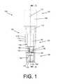
- FIG. 1depicts a side view of a first example embodiment of an SCBI
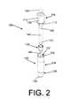
- FIG. 2depicts an isometric exploded view of the first SCBI example depicted in FIG. 1 ;
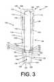
- FIG. 3depicts a cross-section of the first SCBI example depicted in FIGS. 1-2 taken along line A-A of FIG. 1 ;
- FIG. 4depicts an isometric view of a first example embodiment of an insert of the first SCBI example depicted in FIGS. 1-3 ;
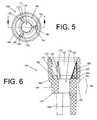
- FIG. 5depicts an top view of the first example embodiment of the insert of FIG. 4 ;
- FIG. 6depicts a cross section of the first example embodiment of the insert of FIGS. 4-5 taken along line B-B of FIG. 5 ;
- FIG. 7depicts an isometric view of a second example embodiment of an SCBI.
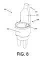
- FIG. 8depicts an isometric view of a second example embodiment of an insert of the second SCBI example depicted in FIG. 7 ;
- SCBI 100includes a housing 102 and a cap 104 .
- Cap 104includes an inner surface 106 , an outer surface 108 , and a projection 112 that has a planar, angled, arcuate, annular, or conical shape, or some combination thereof.
- Cap 104may further include one or more through-holes 110 , to assist in the passage of gasses (e.g., air or sterilant) into or out from the SCBI.
- a chemical indicator 196which may be a sticker that changes color when exposed to a sterilant, may be affixed to the cap.
- Inner surface 106may additionally include a curved portion 156 .
- Housing 102includes a side wall 114 having an inner side wall 116 and an outer side wall 118 , a bottom wall 120 having an inner bottom wall 122 and an outer bottom wall 126 . Housing 102 further includes a support 130 formed by a constriction of side wall 114 . Top end 134 of housing 102 may define an aperture 132 therethrough, opposite bottom wall 120 . Housing 102 may further be defined by a top portion 124 and a bottom portion 128 with support 130 disposed therebetween, further defining within housing 102 a first enclosure 136 and a second enclosure 138 .
- Cap 104is disposed relative to housing 102 in a first position and is configured to be movable from the first position to a second position, as is known in the art of SCBIs.
- Cap 104is coupled to housing 102 in a manner in which gases (e.g., air or sterilant) may move from the surrounding environment and into the SCBI, or vice versa.
- gasese.g., air or sterilant
- any through-holes 110 in cap 104are disposed above top end 134 such that first enclosure 136 and second enclosure 138 are in fluid communication with the surrounding environment, which permits introduction and withdrawal of sterilant into and from first enclosure 136 and second enclosure 138 via through-holes 110 .
- Cap 104may be depressed into a second position relative to housing 102 .
- through-holes 110are disposed below top end 134 with cap 104 and outer side wall 118 in a tight-fitting relationship, which obstructs through-holes 110 , effectively sealing the first enclosure 136 and second enclosure 138 from the surrounding environment.
- SCBI 100also includes a source of microorganisms or active enzymes, such as carrier 140 , which is impregnated with bacterial spores, other forms of bacteria (e.g., vegetative), and/or active enzymes.
- carrier 140may be impregnated with spores from Bacillus, Geobacillus , and/or Clostridia species.
- Carrier 140may be water-absorbent and may be formed of filter paper.
- carrier 140can be constructed of a combination of the aforementioned materials. In some embodiments, carrier 140 rests upon inner bottom wall 122 . In some embodiments, carrier 140 may have a thickness of approximately 0.1 to 0.5 millimeters.
- SCBI 100also includes a frangible glass ampule 142 , having a first end 143 and a second end 144 .
- Ampule 142may contain a liquid growth medium.
- the growth mediumshould be capable, with incubation, of promoting growth of any viable microorganisms disposed on carrier 140 .
- the growth mediumdoes not promote growth of, e.g., contaminating microorganisms that were not purposefully disposed on carrier 140 because such contaminants could cause a color or fluorescence change, which could lead to incorrect determinations of sterilization efficacy.
- Ampule 142may also include, either within or separate from the growth medium, a growth indicator.
- the growth indicatormay be an enzyme or dye, e.g., a fluorescent dye, which aids in detecting growth of surviving microorganisms.
- the growth indicatormay also be an enzyme substrate system, which may be a substance or mixture of substances that an enzyme may act upon and convert into an enzyme-modified product or products.
- the enzyme substrate systemmay be a fluorogenic substrate that fluoresces differently than an enzyme-modified product produced by a reaction between an enzyme and the fluorogenic substrate. In some embodiments, the fluorogenic substrate fluoresces little if at all and the enzyme-modified product fluoresces significantly more than the substrate.
- SCBI 100may also include an insert 146 , which is detailed in FIGS. 3-6 .
- Insert 146may include a platform 148 having a top surface 150 , an abutment surface 152 , a bottom surface 153 , and one or more side surfaces, such as lower side surface 154 , and upper side surface 155 .
- Insert 146may also include a tubular wall portion 164 on platform 148 that originates from top surface 150 and/or side surface 154 and extends away from abutment surface 152 .
- Tubular wall portion 164may have a hollow-cylindrical form. The diameter of this cylinder should be greater than the diameter of ampule 142 such that second end 144 may be disposed within tubular wall portion 164 .
- a first void (or passage) 178may be disposed through platform 148 .
- First void 178may have the form of a bore that originates in top surface 150 and terminates in bottom surface 153 .
- a second void (or passage) 188may additionally or alternatively be disposed through platform 148 .
- Second void 188may have the form of an angled cut (e.g., chamfer or bevel) that originates, at least partially, in side surface 154 and terminates, at least partially, in abutment surface 152 .
- void 188may additionally intersect top surface 150 .
- Insert 146may include additional instances of void 178 and void 188 .
- three instances of void 188are disposed through platform 148 from upper side surface 155 to abutment surface 152 .
- Insert 146may also include a leg (or legs) 166 that originates from bottom surface 153 and extends away from platform 148 .
- Leg 166has a maximum length equal to the distance between support 130 and inner bottom wall 122 of housing 102 . As shown in FIG. 3 , leg 166 has a length that is somewhat less than the distance between support 130 and inner bottom wall 122 of housing 102 . Leg 166 may have a length that is approximately 0.1 to 1 millimeter less than the distance between support 130 and inner bottom wall 122 of housing 102 .
- Insert 146may include multiple instances of leg 166 . For example, insert 146 may include three instances of leg 166 .
- Insert 146may also include a protrusion, or stress concentrator, 170 disposed upon top surface 150 of platform 148 .
- Stress concentrator 170may have the form of, e.g., a rounded bump, an angled bump, or a wedge, such as a triangular wedge. As shown in FIGS. 3-6 , stress concentrator 170 has the form of a triangular wedge.
- the triangular wedgemay have the form of a right triangle, including a base portion 171 , a height portion 172 , and a hypotenuse portion 173 .
- Base portion 171may be coincident with top surface 150 and height portion 172 may be coincident with upper side surface 155 and/or tubular wall portion 164 .
- stress concentrator 170may function as a gusset that may strengthen the junction of tubular wall portion 164 and platform 148 .
- Base portion 171may be disposed at a first angle ⁇ to hypotenuse portion 173 .
- the first angle ⁇may be acute.
- the first anglemay have a value between 45° and 85°.
- Insert 146may additionally include multiple stress concentrators.
- stress concentrator 170it may also include a stress concentrator 180 and a stress concentrator 190 .
- stress concentrators 180 and 190may also each have the form of, e.g., a rounded bump, an angled bump, or a wedge, such as a triangular wedge.
- stress concentrator 180has a triangular form and includes a base portion 181 , a height portion 182 , and a hypotenuse portion 183 .
- Stress concentrator 190also has a triangular form that includes a base portion 191 , a height portion 192 , and a hypotenuse portion 193 .
- Base portion 181may be disposed at a second angle, ( 3 , to hypotenuse portion 183 and base portion 191 may be disposed at a third angle, y, to hypotenuse portion 193 .
- the second angle and the third anglemay be acute.
- the second angle and the third anglemay have a value between 45° and 85°.
- the second angle and third anglemay be equal to each other and to the first angle.
- the second angle and third anglemay be equal to each other but unequal to the first angle.
- the first angle, second angle, and third anglemay each be unequal to each other.
- Insert 146may be fabricated as an assembly of multiple components or may be manufactured as a single component, e.g., by injection molding.
- Insert 146is disposed within SCBI 100 .
- abutment surface 152 of platform 148rests upon—or abuts—support 130 .
- abutment surface 152 and support 130together define a boundary between first enclosure 136 and second enclosure 138 of housing 102 .
- Leg or legs 166thus extend into second enclosure 138 and help maintain the position of carrier 140 , which rests on inner bottom wall 122 and should remain there throughout the SCBI's life cycle.
- leg or legs 166being shorter than the distance between support 130 and inner bottom wall 122 , they do not contact inner bottom wall 122 .
- carrier 140is sufficiently thin such that a clearance is also maintained between leg or legs 166 and carrier 140 .
- Such clearanceshould help prevent damage to carrier 140 that otherwise could occur while the SCBI is being transported from a manufacturer's manufacturing facility to, e.g., a warehouse or a healthcare facility.
- Such transportationmay be conducted by e.g., the manufacturer, an agent or employee of the manufacturer, or a common carrier (e.g., the United States Postal Service, the United Parcel Service).
- a common carriere.g., the United States Postal Service, the United Parcel Service.
- the SCBImay be subject to repeated jostling, caused by, e.g., bumps in roads or train tracks. This jostling could damage carrier 140 if leg or legs 166 were to contact carrier 140 .
- SCBI 100may be loaded onto a standard shipping vehicle, such as a truck, and the vehicle may be driven to a destination, such as a healthcare facility or a warehouse, to transport SCBI 100 to the destination. Personnel at the destination may forego inspecting SCBI 100 for damage to carrier 140 based on the increased assurance that carrier 140 is not prone to damage during transportation.
- legs 166may include thereon a retaining ledge, such as a ring that connects the legs, the ring having a diameter equal to or approximately equal to a diameter or a width of carrier 140 .
- the retaining ledgemay be spaced from carrier 140 by up to 0.4 mm. Alternatively, it may contact carrier 140 at an outer edge of carrier 140 .
- the position of glass ampule 142is maintained within SCBI 100 by insert 146 and cap 104 in its first position such that ampule 142 does not contact housing 104 .
- Curved portion 156may assist in maintaining the position of ampule 142 .
- a portion of ampule 142is disposed within first enclosure 136 and a portion of ampule 142 is disposed above top end 134 of housing 102 but within cap 104 .
- second end 144 of glass ampule 142rests against platform 148 , or any one or more of stress concentrators 170 , 180 , and 190 , such that second end 144 is disposed within tubular wall portion 164 of insert 146 .
- Second end 144 of glass ampule 142may contact stress concentrator 170 at a first point, stress concentrator 180 at a second point, and stress concentrator 190 at a third point.
- First end 143 of ampule 142is disposed within cap 104 .
- first end 143 of ampule 142may contact inner surface 106 of cap 104 , and in some embodiments, curved portion 156 , such that glass ampule 142 is constrained from vertical movement by its contacts with cap 104 and insert 146 .
- first end 143 of ampule 142may also be disposed within projection 112 .
- Projection 112may be configured to form a tight fit with ampule 142 . Where projection 112 is of an annular form, projection 112 may have a diameter similar to or equal to the diameter of ampule 142 . Accordingly, there may be a friction fit between ampule 142 and projection 112 . Alternatively, the diameter of projection 112 may be slightly larger than the diameter of ampule 142 to provide between approximately 0.1 mm and 3 mm of clearance between the ampule 142 and the projection 112 .
- the overall position of ampule 142may be maintained within SCBI 100 until the time a user desires to use the SCBI, which may help prevent premature breakage of glass ampule 142 , particularly during transportation from a manufacturing facility to another site, such as a healthcare facility.
- SCBI 100is subjected to a sterilization cycle, preferably alongside medical devices being sterilized by the sterilization cycle.
- a useractivates SCBI 100 by applying force to cap 104 , either using his or her hand or other body part, and/or with the assistance of a device adapted to aid the user in applying force to cap 104 .
- Cap 104and in some embodiments, curved portion 156 , applies at least some of the force the user exerted on cap 104 to ampule 142 , which generates a reaction force between cap 104 and top end 143 .
- Ampule 142via bottom end 144 , applies at least some of the force the user applied to cap 104 to stress concentrators 170 , 180 , and 190 of insert 146 , which in turn generates a reaction force between bottom end 143 and stress concentrators 170 , 180 , and 190 of insert 146 .
- Insert 146via support 130 , applies at least some of the force the user applied to cap 104 to abutment surface 152 , which generates a reaction force between abutment surface 152 and support 130 .
- Ampule 142being fabricated from glass, fractures into glass shards when the force applied by the user to cap 104 generates stresses within ampule 142 that are greater than ampule 142 can withstand.
- Stress concentrators 170 , 180 , and 190aid in increasing the stress within ampule 142 for a given force that the user applies directly to cap 104 and indirectly to ampule 142 because the surface area of the points of contact between bottom end 144 of ampule 142 and stress concentrators 170 , 180 , and 190 is less than the surface area of cap 104 to which a user applies force to activate the SCBI and/or less than the surface area of the points of contact between cap 104 , which may include curved portion 156 , and top end 143 of ampule 142 .
- ampule 142is no longer present to resist the force applied by the user to the cap. Accordingly, the force applied by the user causes cap 104 to move to a second position in which the cap effectively seals SCBI 100 .
- Insert 146prevents the glass shards from entering second enclosure 138 such that some glass shards settle on platform 148 and the remaining glass shards settle on top of other glass shards.
- the fracturing of ampule 142also releases some volumes of the liquid growth medium to flow downward through the shards and through void 178 , ultimately collecting in second enclosure 138 .
- Other volumes of the liquid growth mediumare projected toward inner side wall 116 of housing 102 . Some of these volumes impinge upon inner side wall 116 and then flow downward to pass through space between inner side wall 116 and insert 146 , ultimately collecting in second enclosure 138 .
- Voids 178 and 188provide openings through which fluids such as the growth medium, gases (e.g., air), vapors, and sterilant may flow. These openings function as passages that help maintain fluid communication within housing 102 between first enclosure 136 and second enclosure 138 .
- void 178helps maintain fluid communication through insert 146 and void 188 helps maintain fluid communication along the side of insert 146 , between wall 164 and inner side wall 116 of housing 102 .
- Voids 178 and 188may further facilitate the flow of liquid growth medium into second enclosure 138 by way of reducing the impedance to the downward flow of the liquid growth medium otherwise caused by the glass shards, platform 148 , and the gas within second enclosure 138 that must be displaced for the liquid growth medium to enter. Voids 178 and 188 reduce the likelihood that gas within second enclosure 138 may become trapped by volumes of the liquid growth medium that pool, e.g., between pieces of glass shards, which could prevent displacement of the gas within second enclosure 138 and, correspondingly, prevent the full volume of the liquid growth medium from entering second enclosure 138 .
- This mechanismcould result in maintaining a volume of the liquid growth medium in the first enclosure, away from carrier 140 , which could prevent a successful culture of any microorganisms on carrier 140 that may have survived the sterilization cycle, which could in turn increase the likelihood of an erroneous determination of the cycle's efficacy.
- the likelihood of a liquid lock formingis further reduced, or inhibited, by allowing volumes of liquid the growth medium to impinge, largely unobstructed, upon inner side wall 116 above support 130 because the surface area of inner side wall 116 that the liquid may initially wet is maximized, which allows a greater volume of the liquid to flow downward along inner side wall 116 , instead of through the concentration of glass shards that collect upon insert 146 .
- the likelihood that liquid may pool between pieces of the shards and form a liquid lockis minimized.
- insert 146includes stress concentrators 170 , 180 , and 190 . Glass ampule 142 rests upon these stress concentrators. Specifically, second end 144 of glass ampule 142 contacts stress concentrator 170 at a first point, stress concentrator 180 at a second point, and stress concentrator 190 at a third point.
- force applied to cap 104causes reaction pressure to be concentrated at these three points.
- pressureis inversely proportional to surface area.
- reactive pressureis maximized by minimizing the surface area that resists the force that cap 104 applies to ampule 142 .
- the three pointsthus maximize the reactive pressure against the glass ampule.
- one or two pointsmay result in a greater reactive pressure, in some embodiments three points of contact may be used in order to maintain the position of ampule 142 as described above.
- stress concentrators 170 , 180 , and 190need not be identical. For example, although they may each have a triangular form, the angle between their respective base portions ( 171 , 181 , 191 ) and hypotenuse portions ( 173 , 183 , 193 ) may differ somewhat. When these angles differ, the resistive forces applied by stress concentrators 170 , 180 , and 190 to ampule 142 are applied asymmetrically. It is believed that this asymmetric application of force causes an increase in the stress generated in ampule 142 , thereby reducing the amount of force the user must apply to cap 104 in order to break ampule 142 .
- a further asymmetry between the forcesmay be achieved in those embodiments where inner surface 106 of cap 104 contacts ampule 142 in an asymmetric manner.
- curved portion 156contacts first end 143 on the left side 105 of first end 143 , but not on the right side 107 of first end 143 . Accordingly, a downward force applied by the user to cap 104 results in cap 104 imparting a force to ampule 142 that includes a lateral component.
- ampule 142may be broken following the application of an applied force to cap 104 that generates at least four resistive forces at discrete locations upon ampule 142 . These resistive forces occur at least where ampule 142 contacts: (1) inner surface 106 of cap 104 , which in some embodiments includes curved portion 156 , (2) stress concentrator 170 , (3) stress concentrator 180 , and (4) stress concentrator 190 .
- SCBI 200includes insert 246 , a housing 202 , and a cap 204 .
- Insert 246includes a tubular wall portion 264 . Originating from tubular wall portion 264 is an arm (or finger) 251 .
- Arm 251has a top portion 253 and a bottom portion 255 . Bottom portion 255 is disposed upon and connected to tubular wall portion 264 .
- Arm 251is fabricated from a semi-rigid material, such as plastic, and has a thickness such that arm 251 may flex when subject to compressive and/or lateral force.
- arm 251may laterally flex about bottom portion 255 where arm 251 connects to tubular wall portion 264 .
- Arm 251may be hollow or have one or more channels or apertures disposed therein to reduce the amount of force required to cause arm 251 to deflect. The channels or apertures may also help prevent arm 251 from blocking the liquid growth medium from impinging on inner side wall 216 when ampule 242 is broken, which is important for minimizing the likelihood of a liquid lock, as explained above with respect to SCBI 100 .
- Insert 246may be fabricated as an assembly of multiple components or may be manufactured as a single component, e.g., by injection molding.
- Cap 204includes a projection 212 that has a planar, angled, arcuate, annular, or conical shape, or some combination thereof.
- arm 251is configured in a manner whereby top portion 253 of arm 251 is disposed in proximity of projection 212 .
- top portion 253may contact projection 212 .
- theremay be approximately 0.1 mm to 5 mm of lateral and/or vertical clearance between top portion 253 and projection 212 .
- SCBI 200functions similarly to SCBI 100 , but less force may be applied to cap 204 of SCBI 200 in order to break glass ampule 242 than may be applied to cap 104 of SCBI 100 in order to break glass ampule 142 because of arm 251 .
- arm 251impedes movement of cap 204 by way of interference because arm 251 is an obstruction in the path of projection 212 .
- Arm 251is not a complete obstruction, however, because it may flex about its connection to tubular wall portion 264 toward inner side wall 216 from a first orientation to a second orientation. In some configurations, the flexion of arm 251 is limited by inner side wall 216 .
- insert 246may include multiple stress concentrators.
- a first stress concentrator 270is visible in FIG. 8 .
- three stress concentratorsmay be employed, similar to insert 146 . It is believed that this asymmetric application of force causes an increase in the stress generated in ampule 242 , thereby reducing the amount of force the user must apply to cap 204 in order to break ampule 242 .
- ampule 242may be broken following the application of an applied force to cap 204 that generates at least five reaction forces at discrete locations upon ampule 242 . These reaction forces occur at least where (1) top portion 243 of ampule 242 contacts cap 204 , (2) ampule 242 contacts first stress concentrator 270 , (3) ampule 242 contacts the second stress concentrator, (4) ampule 242 contacts the third stress concentrator, and (5) arm 251 deflects stress concentrator 212 into ampule 242 .
- arm 251 and projection 212may be reversed such that projection 212 is closer to inner side wall 216 than arm 251 and such that arm 251 contacts ampule 242 to help maintain its position within housing 202 .
- projection 212applies a lateral force to arm 251 , which in turn applies a lateral force to glass ampule 242 .
Landscapes
- Health & Medical Sciences (AREA)
- Chemical & Material Sciences (AREA)
- Life Sciences & Earth Sciences (AREA)
- Organic Chemistry (AREA)
- Engineering & Computer Science (AREA)
- Zoology (AREA)
- Wood Science & Technology (AREA)
- General Health & Medical Sciences (AREA)
- Bioinformatics & Cheminformatics (AREA)
- Proteomics, Peptides & Aminoacids (AREA)
- Public Health (AREA)
- Epidemiology (AREA)
- Biotechnology (AREA)
- Genetics & Genomics (AREA)
- Microbiology (AREA)
- Biochemistry (AREA)
- General Engineering & Computer Science (AREA)
- Analytical Chemistry (AREA)
- Molecular Biology (AREA)
- Immunology (AREA)
- Biophysics (AREA)
- Physics & Mathematics (AREA)
- Veterinary Medicine (AREA)
- Animal Behavior & Ethology (AREA)
- Biomedical Technology (AREA)
- Sustainable Development (AREA)
- Toxicology (AREA)
- Medicinal Chemistry (AREA)
- Apparatus For Disinfection Or Sterilisation (AREA)
- Apparatus Associated With Microorganisms And Enzymes (AREA)
- Measuring Or Testing Involving Enzymes Or Micro-Organisms (AREA)
Abstract
Description
Claims (14)
Priority Applications (18)
| Application Number | Priority Date | Filing Date | Title |
|---|---|---|---|
| US15/057,768US10907126B2 (en) | 2016-03-01 | 2016-03-01 | Self-contained biological indicator |
| CA2958387ACA2958387A1 (en) | 2016-03-01 | 2017-02-17 | Self-contained biological indicator |
| AU2017201194AAU2017201194B2 (en) | 2016-03-01 | 2017-02-22 | Self-contained biological indicator |
| BR122022000065-7ABR122022000065B1 (en) | 2016-03-01 | 2017-02-23 | Biological indicator of sterilization and activation method |
| TW106106039ATWI739807B (en) | 2016-03-01 | 2017-02-23 | Self-contained biological sterilization indicator |
| BR122022000063-0ABR122022000063B1 (en) | 2016-03-01 | 2017-02-23 | Biological indicator of sterilization |
| BR102017003826-2ABR102017003826B1 (en) | 2016-03-01 | 2017-02-23 | Self-contained biological indicator |
| KR1020170025336AKR20170102426A (en) | 2016-03-01 | 2017-02-27 | Self-contained biological indicator |
| RU2017106341ARU2758780C2 (en) | 2016-03-01 | 2017-02-28 | Autonomous biological indicator |
| MX2017002664AMX386475B (en) | 2016-03-01 | 2017-02-28 | SELF-CONTAINED BIOLOGICAL INDICATOR. |
| JP2017035967AJP7043177B2 (en) | 2016-03-01 | 2017-02-28 | Built-in biological indicator |
| CN201710118914.1ACN107137741B (en) | 2016-03-01 | 2017-03-01 | Self-contained biological indicator |
| EP17158744.7AEP3260141A1 (en) | 2016-03-01 | 2017-03-01 | Self-contained biological indicator |
| US17/155,970US11965151B2 (en) | 2016-03-01 | 2021-01-22 | Self-contained biological indicator |
| AU2022200256AAU2022200256B2 (en) | 2016-03-01 | 2022-01-16 | Self-contained biological indicator |
| JP2022041221AJP2022069598A (en) | 2016-03-01 | 2022-03-16 | Self-contained biological indicator |
| JP2024025364AJP2024045718A (en) | 2016-03-01 | 2024-02-22 | Self-contained biological indicator |
| US18/616,444US20240228937A1 (en) | 2016-03-01 | 2024-03-26 | Self-Contained Biological Indicator |
Applications Claiming Priority (1)
| Application Number | Priority Date | Filing Date | Title |
|---|---|---|---|
| US15/057,768US10907126B2 (en) | 2016-03-01 | 2016-03-01 | Self-contained biological indicator |
Related Child Applications (1)
| Application Number | Title | Priority Date | Filing Date |
|---|---|---|---|
| US17/155,970DivisionUS11965151B2 (en) | 2016-03-01 | 2021-01-22 | Self-contained biological indicator |
Publications (2)
| Publication Number | Publication Date |
|---|---|
| US20170253845A1 US20170253845A1 (en) | 2017-09-07 |
| US10907126B2true US10907126B2 (en) | 2021-02-02 |
Family
ID=58347056
Family Applications (3)
| Application Number | Title | Priority Date | Filing Date |
|---|---|---|---|
| US15/057,768Active2036-07-04US10907126B2 (en) | 2016-03-01 | 2016-03-01 | Self-contained biological indicator |
| US17/155,970Active2037-05-26US11965151B2 (en) | 2016-03-01 | 2021-01-22 | Self-contained biological indicator |
| US18/616,444PendingUS20240228937A1 (en) | 2016-03-01 | 2024-03-26 | Self-Contained Biological Indicator |
Family Applications After (2)
| Application Number | Title | Priority Date | Filing Date |
|---|---|---|---|
| US17/155,970Active2037-05-26US11965151B2 (en) | 2016-03-01 | 2021-01-22 | Self-contained biological indicator |
| US18/616,444PendingUS20240228937A1 (en) | 2016-03-01 | 2024-03-26 | Self-Contained Biological Indicator |
Country Status (11)
| Country | Link |
|---|---|
| US (3) | US10907126B2 (en) |
| EP (1) | EP3260141A1 (en) |
| JP (3) | JP7043177B2 (en) |
| KR (1) | KR20170102426A (en) |
| CN (1) | CN107137741B (en) |
| AU (2) | AU2017201194B2 (en) |
| BR (3) | BR122022000063B1 (en) |
| CA (1) | CA2958387A1 (en) |
| MX (1) | MX386475B (en) |
| RU (1) | RU2758780C2 (en) |
| TW (1) | TWI739807B (en) |
Cited By (2)
| Publication number | Priority date | Publication date | Assignee | Title |
|---|---|---|---|---|
| WO2022069937A1 (en) | 2020-09-29 | 2022-04-07 | Asp Global Manufacturing Gmbh | Medical device sterilization system with plasma-based detection of residual alcohol |
| US11565015B2 (en) | 2016-09-15 | 2023-01-31 | Asp Global Manufacturing Gmbh | Biological indicator with variable resistance |
Families Citing this family (20)
| Publication number | Priority date | Publication date | Assignee | Title |
|---|---|---|---|---|
| US10907126B2 (en) | 2016-03-01 | 2021-02-02 | Asp Global Manufacturing Gmbh | Self-contained biological indicator |
| US10561753B2 (en) | 2016-03-02 | 2020-02-18 | Asp Global Manufacturing Gmbh | Method of sterilizing medical devices, analyzing biological indicators, and linking medical device sterilization equipment |
| US10443083B2 (en) | 2016-03-02 | 2019-10-15 | Asp Global Manufacturing Gmbh | Apparatus and method for analyzing biological indicators |
| US10668180B2 (en) | 2016-03-02 | 2020-06-02 | Asp Global Manufacturing Gmbh | Apparatus and method for sterilizing medical devices |
| US11242505B2 (en)* | 2017-01-03 | 2022-02-08 | Asp Global Manufacturing Gmbh | Self-contained biological indicator |
| US11248250B2 (en)* | 2017-12-01 | 2022-02-15 | Asp Global Manufacturing Gmb | Self-contained biological indicator |
| CN108190229B (en)* | 2017-12-18 | 2023-05-23 | 温州微穹微生物技术有限公司 | Biological indicator packaging bottle |
| ES3025537T3 (en)* | 2018-05-16 | 2025-06-09 | Seitz Hiemer Sogaro Gbr | Applicator |
| US11000614B2 (en) | 2018-06-28 | 2021-05-11 | Asp Global Manufacturing Gmbh | System and method for automating verification of medical instrument sterilization compatibility and sterilization cycle selection |
| CN112437676A (en)* | 2018-07-27 | 2021-03-02 | 3M创新有限公司 | Self-contained biological indicator |
| CN109897774B (en)* | 2018-08-08 | 2022-08-09 | 珠海市慧康生物科技有限公司 | A device for quick sterilization of microbial cultivation base |
| CN112469448A (en)* | 2018-08-21 | 2021-03-09 | Gke德国有限责任公司 | Multi-stage process challenge device, indicator system and process challenge device system |
| US11850320B2 (en) | 2018-12-20 | 2023-12-26 | Asp Global Manufacturing Gmbh | Liquid-chemical sterilization system with biological indicator |
| EP3902569B1 (en) | 2018-12-28 | 2025-09-24 | ASP Global Manufacturing GmbH | A treatment indicator, a method of production thereof, and a method of use thereof |
| CN114450036B (en)* | 2019-09-20 | 2024-06-14 | 爱思帕全球制造有限公司 | Biological indicator for use with liquid sterilant |
| CN115315522B (en)* | 2020-03-17 | 2025-08-08 | 舒万诺知识产权公司 | Fixed pH indicator for growth indication of biological indicators |
| US20210349033A1 (en)* | 2020-05-07 | 2021-11-11 | Thomas James Riha | Intelligent reader and data recording system for biological, chemical, and instant biological and enzymatic sterilization indicators |
| CN111575338B (en)* | 2020-06-12 | 2025-03-21 | 山东新华医疗器械股份有限公司 | A biological sterilization indicator |
| MX2023005304A (en) | 2020-11-10 | 2023-06-23 | Advanced Sterilization Products Inc | Ampoule breaker for a biological indicator. |
| US11603551B2 (en) | 2020-12-02 | 2023-03-14 | Steritec Products Mfg. Co., Inc. | Biological indicators, and systems and methods for determining efficacy of sterilization |
Citations (96)
| Publication number | Priority date | Publication date | Assignee | Title |
|---|---|---|---|---|
| CA738687A (en) | 1966-07-19 | R. Ernst Robert | Biological sterility indicator and method for using same | |
| GB1055387A (en) | 1963-04-10 | 1967-01-18 | Wilmot Castle Co | Biological sterility indicator and method for using same |
| US3346464A (en) | 1965-10-23 | 1967-10-10 | Ritter Pfaudler Corp | Biological sterility indicator and method for making and using same |
| CA823163A (en) | 1969-09-16 | R. Ernst Robert | Biological sterility indicator and method for making same | |
| US3752743A (en) | 1972-03-15 | 1973-08-14 | Colab Lab Inc | Biological indicator |
| US3948727A (en) | 1973-06-07 | 1976-04-06 | Veb Kombinat Medizin-Und Labortechnik | Biological indicator and method of production thereof |
| US4291122A (en) | 1980-08-14 | 1981-09-22 | American Sterilizer Company | Biological indicator for sterilization processes |
| US4304869A (en) | 1980-05-27 | 1981-12-08 | American Sterilizer Company | Apparatus for rupturing a sealed, frangible container |
| CA1182729A (en) | 1981-09-30 | 1985-02-19 | David A. Karle | Contamination-free sterilization indicating system |
| US4528268A (en) | 1981-12-31 | 1985-07-09 | H. W. Andersen Products Inc. | Apparatus and method for testing the sufficiency of sterilization |
| EP0152298A2 (en)* | 1984-02-10 | 1985-08-21 | Baxter Travenol Laboratories, Inc. | Apparatus and method for dertermining the effectiveness of sterilization |
| US4546086A (en) | 1983-01-19 | 1985-10-08 | Hounsell Melvin W | Microbial culture apparatus |
| US4717661A (en) | 1986-01-21 | 1988-01-05 | Castle Company | Biological indicator for sterilization processes |
| US4732850A (en) | 1985-07-05 | 1988-03-22 | E. R. Squibb & Sons, Inc. | Frangible container with rupturing device |
| US4839291A (en) | 1987-05-15 | 1989-06-13 | American Sterilizer Company | Disposable biological indicator test pack for monitoring steam and ethylene oxide sterilization cycles |
| US4883641A (en) | 1987-06-26 | 1989-11-28 | Minnesota Mining And Manufacturing Company | Closure and container assembly for biological sterility indicator |
| US4885253A (en) | 1989-03-27 | 1989-12-05 | Steris Corporation | Universal biological indicator system |
| EP0371682A2 (en) | 1988-11-29 | 1990-06-06 | Minnesota Mining And Manufacturing Company | Rapid method for determining efficacy of a sterilization cycle and rapid read-out biological indicator |
| US5028543A (en) | 1988-03-18 | 1991-07-02 | Dexsil Corporation | Method for measuring the content of halogenated organic compounds in soil samples |
| WO1992019764A1 (en) | 1991-05-08 | 1992-11-12 | Baxter Diagnostics Inc. | Method and apparatus to detect bacterial contamination of transfusable blood |
| US5167923A (en) | 1989-09-28 | 1992-12-01 | Pymah Corporation | Sterility indicator |
| US5223401A (en) | 1988-11-29 | 1993-06-29 | Minnesota Mining And Manufacturing Company | Rapid read-out sterility indicator |
| US5252484A (en) | 1988-11-29 | 1993-10-12 | Minnesota Mining And Manufacturing Company | Rapid read-out biological indicator |
| US5362654A (en) | 1984-07-20 | 1994-11-08 | Sangstat Medical Corporation | Self-contained quantitative assay |
| US5405580A (en) | 1993-09-24 | 1995-04-11 | American Sterilizer Company | Self-contained biological indicators |
| US5415994A (en) | 1993-08-02 | 1995-05-16 | Quidel Corporation | Lateral flow medical diagnostic assay device with sample extraction means |
| FR2708287B1 (en) | 1993-07-01 | 1995-10-20 | Mahwachi Mongi | Sterilization indicator device. |
| US5516648A (en) | 1994-08-18 | 1996-05-14 | Steris Corporation | Encapsulated biological indicator |
| US5552320A (en) | 1993-08-09 | 1996-09-03 | Johnson & Johnson Medical, Inc. | Self-contained biological indicator |
| WO1997035189A1 (en) | 1996-03-20 | 1997-09-25 | University Of Washington | Fluorescent reporter beads for fluid analysis |
| US5736355A (en) | 1996-05-13 | 1998-04-07 | Steris Corporation | Self contained biological indicator |
| US5739004A (en) | 1993-05-20 | 1998-04-14 | Minnesota Mining And Manufacturing Company | Biological sterilization indication for use with or without test pack materials or devices |
| US5750184A (en) | 1995-12-19 | 1998-05-12 | Pharmaceutical Systems, Inc. | Unitary biological indicator for gaseous sterilants and process |
| US5759848A (en) | 1996-05-14 | 1998-06-02 | Fujiyakuhin Co., Ltd. | Biological indicator |
| US5770393A (en) | 1997-04-01 | 1998-06-23 | Steris Corporation | Biological indicator for detection of early metabolic activity |
| JPH10201466A (en) | 1997-01-21 | 1998-08-04 | Showa Yakuhin Kako Kk | Biological indicator |
| US5801010A (en) | 1997-03-17 | 1998-09-01 | Surigot, Inc. | Self-contained biological indicator for non traditional sterilization methods |
| US5830683A (en) | 1996-01-22 | 1998-11-03 | North American Science Associates, Inc. | Indicator systems for determination of sterilization |
| US5863790A (en) | 1997-05-14 | 1999-01-26 | Minnesota Mining And Manfacturing Company | Biological sterility indicator |
| US5866356A (en) | 1997-10-20 | 1999-02-02 | Minnesota Mining And Manufacturing Company | Protective housing for biological indicator for testing the effectiveness of a sterilization procedure |
| JPH11196893A (en) | 1998-01-06 | 1999-07-27 | Pharmaceutical Syst Inc | Integral biological indicator for sterilizing gas and sterilization of gas using the same |
| US5942438A (en) | 1997-11-07 | 1999-08-24 | Johnson & Johnson Medical, Inc. | Chemical indicator for oxidation-type sterilization processes using bleachable dyes |
| WO2000050634A1 (en) | 1999-02-22 | 2000-08-31 | 3M Innovative Properties Company | Sterilization indicator for liquid peracetic acid procedures |
| US6436659B1 (en) | 2000-10-27 | 2002-08-20 | Ethicon, Inc. | Biological indicator for sterilization processes with double buffer system |
| EP1032822B1 (en) | 1997-11-10 | 2003-05-07 | Minnesota Mining And Manufacturing Company | Apparatus for reading a plurality of biological indicators |
| US20050014214A1 (en) | 2003-07-16 | 2005-01-20 | Steris Inc. | Self-contained biological indicator |
| WO2005036128A2 (en) | 2003-10-02 | 2005-04-21 | Sgm Biotech, Inc. | Bacterial lethality test indicator and prompt response spectroscopic analyzer |
| US7091042B2 (en) | 2001-11-02 | 2006-08-15 | Ethicon, Inc. | Variable resistance sterilization process challenge device and method |
| CN1853734A (en) | 2005-03-30 | 2006-11-01 | 伊西康公司 | Integrator system and method for rapidly determining effectiveness of a germicidal treatment |
| US20080070272A1 (en) | 2006-09-20 | 2008-03-20 | Franciskovich Phillip P | Sterilization indicator |
| WO2008106327A2 (en) | 2007-02-27 | 2008-09-04 | American Sterilizer Company | Biological indicator for use with vaporous microbial deactivating agents and method for making same |
| US20090068716A1 (en) | 2006-04-11 | 2009-03-12 | Ngk Insulators, Ltd. | Biological indicator and method for producing the same |
| US7642067B2 (en) | 2005-06-30 | 2010-01-05 | Ethicon, Inc. | Device and method for rapidly determining the effectiveness of sterilization or disinfection processes |
| CN201453688U (en) | 2009-07-07 | 2010-05-12 | 山东鲁泰环中制药有限公司 | Energy-efficient mechanized-door ampoule sterilizer |
| US20110200992A1 (en) | 2008-10-17 | 2011-08-18 | Sailaja Chandrapati | Biological Compositions, Articles and Methods for Monitoring Sterilization Processes |
| US8173438B1 (en) | 1996-10-08 | 2012-05-08 | Photonic Biosystems, Inc. | Microbiological assessment method and device utilizing oxygen gradient sensing |
| US8173388B2 (en) | 2008-09-30 | 2012-05-08 | American Sterilizer Company | Self-contained biological indicator |
| US20120149094A1 (en) | 2009-07-20 | 2012-06-14 | Smith Jeffrey D | Biological Sterilization Indicator and Method of Using Same |
| US20120156090A1 (en) | 2010-12-16 | 2012-06-21 | Symmetry Medical Manufacturing, Inc. | Apparatus and Method for Accessing a Biological Indicator within a Container |
| CN102596261A (en) | 2009-10-09 | 2012-07-18 | 赛诺菲-安万特德国有限公司 | Sterilization apparatus and method for controlling of a sterilization apparatus |
| RU129814U1 (en) | 2012-12-07 | 2013-07-10 | Руслан Григорьевич Котченко | BIOLOGICAL INDICATOR OF CONTROL OF THE PROCESS OF STERILIZATION OF PRODUCTS OF MEDICAL PURPOSE (OPTIONS) |
| US20130210048A1 (en) | 2010-11-01 | 2013-08-15 | 3M Innovative Properties Company | Method of detecting a biological activity |
| US20130217107A1 (en) | 2010-11-01 | 2013-08-22 | 3M Innovative Properties Company | Biological sterilization indicator system and method |
| US20130224849A1 (en) | 2010-11-01 | 2013-08-29 | 3M Innovative Properties Company | Biological sterilization indicator |
| CN203307339U (en) | 2013-06-20 | 2013-11-27 | 赵晓菲 | Biological indicating sterilizing effect authentication device of sterilizer |
| US8765398B2 (en) | 2010-05-12 | 2014-07-01 | Mesa Laboratories, Inc. | Biological indicator with integral package |
| US8840837B2 (en) | 2010-11-01 | 2014-09-23 | 3M Innovative Properties Company | Biological sterilization indicator and method of using same |
| RU146719U1 (en) | 2014-06-16 | 2014-10-20 | Василий Александрович Ишутин | BIOLOGICAL INDICATOR FOR CONTROL OF EFFICIENCY OF STERILIZATION AND DISINFECTION OF PRODUCTS |
| US8915413B2 (en) | 2010-04-08 | 2014-12-23 | Medmix Systems Ag | Device for opening an ampoule |
| US8945837B2 (en) | 2013-03-15 | 2015-02-03 | American Sterilizer Company | Sterilization indicator including a simplified genetically engineered biological indicator |
| US8969029B2 (en) | 2008-10-17 | 2015-03-03 | 3M Innovative Properties Company | Biological sterilization indicator, system, and methods of using same |
| US9145573B2 (en) | 2010-11-01 | 2015-09-29 | 3M Innovative Properties Company | Biological sterilization indicator system and method |
| CN105087361A (en) | 2015-09-08 | 2015-11-25 | 湖州一控医疗科技有限公司 | Suspension type biological indicator and preparation method thereof |
| US20150337354A1 (en) | 2012-02-16 | 2015-11-26 | 3M Innovative Properties Company | Biological sterilization indicator devices and methods of use |
| CN204814967U (en) | 2015-07-22 | 2015-12-02 | 青岛高科技工业园海博生物技术有限公司 | Biological indicator sub -assembly |
| US20160000954A1 (en) | 2013-02-26 | 2016-01-07 | 3M Innovative Properties Company | Biological indicator for monitoring a low-temperature sterilization process |
| EP2968634B1 (en) | 2013-03-15 | 2016-12-21 | American Sterilizer Company | Biological indicator for oxidative sterilants |
| WO2016205953A1 (en) | 2015-06-24 | 2016-12-29 | Trojan Technologies | Method for assaying for loss of an organism in an aqueous liquid |
| CN106267277A (en) | 2016-09-28 | 2017-01-04 | 中国科学院苏州生物医学工程技术研究所 | Biological indicator for monitoring lumen class apparatus sterilizing effect detects device |
| US20170175071A1 (en) | 2015-12-17 | 2017-06-22 | Mesa Laboratories, Inc. | Self-contained biological indicator |
| JP2017123976A (en) | 2016-01-13 | 2017-07-20 | 大日本印刷株式会社 | Biological indicator base material, biological indicator, biological indicator base material storage body, biological indicator storage body, biological indicator base material storage body manufacturing method, biological indicator storage body manufacturing method and sterilization apparatus Bactericidal ability evaluation method |
| US20170211035A1 (en) | 2016-01-25 | 2017-07-27 | American Sterilizer Company | Biological indicators |
| US20170253845A1 (en) | 2016-03-01 | 2017-09-07 | Ethicon, Inc. | Self-contained biological indicator |
| CN206473580U (en) | 2016-09-28 | 2017-09-08 | 中国科学院苏州生物医学工程技术研究所 | Biological indicator detection means for monitoring lumen class apparatus sterilizing effect |
| US20180015193A1 (en) | 2014-10-10 | 2018-01-18 | 3M Innovative Properties Company | Biological sterilization indicator with sterilant resistance modulator |
| CN206970617U (en) | 2017-04-13 | 2018-02-06 | 湖州一控医疗科技有限公司 | Simplify the quick bio indicator of structure |
| WO2018025207A1 (en) | 2016-08-03 | 2018-02-08 | 3M Innovative Properties Company | Biological indicator for disinfection process challenge device |
| US20180071421A1 (en) | 2016-09-15 | 2018-03-15 | Ethicon, Inc. | Biological indicator with variable resistance |
| US20180187142A1 (en) | 2017-01-03 | 2018-07-05 | Ethicon, Inc. | Self-contained biological indicator |
| US10059977B2 (en) | 2013-05-21 | 2018-08-28 | 3M Innovative Properties Company | Biological sterilization indicator |
| JP2018201397A (en) | 2017-06-02 | 2018-12-27 | レーベン・ジャパン株式会社 | Biological indicator kit |
| US20190002951A1 (en) | 2017-06-30 | 2019-01-03 | Ethicon, Inc. | Systems and methods for confirming activation of biological indicators |
| RU2683644C2 (en) | 2016-03-02 | 2019-04-01 | Этикон, Инк. | Apparatus and method for analysing biological indicators |
| US20190106726A1 (en) | 2017-10-11 | 2019-04-11 | American Sterilizer Company | Biological indicator |
| US20190106725A1 (en) | 2017-10-11 | 2019-04-11 | American Sterilizer Company | Biological indicator |
| US20190169672A1 (en) | 2017-12-01 | 2019-06-06 | Ethicon, Inc. | Self-contained biological indicator |
Family Cites Families (22)
| Publication number | Priority date | Publication date | Assignee | Title |
|---|---|---|---|---|
| US2447988A (en) | 1946-01-03 | 1948-08-24 | Louis A Pierson | Ampoule neck cutter |
| US3450319A (en) | 1967-03-16 | 1969-06-17 | Millipore Corp | Ampoule breaker |
| US4741437A (en) | 1983-01-31 | 1988-05-03 | North American Science Associates Inc. | Self-contained indicator device |
| US4537099A (en) | 1983-04-15 | 1985-08-27 | Oster Stanley M | Tensioning and braking pliers |
| US4637139A (en) | 1984-12-07 | 1987-01-20 | Fu Chen | Ampoule cutter |
| US5293816A (en) | 1992-12-02 | 1994-03-15 | Musumeci Sr Joseph A | Reduced hand force can crushing apparatus |
| US20040197848A1 (en) | 2003-04-01 | 2004-10-07 | Behun Bryan S. | High throughput biological indicator reader |
| US8173418B2 (en) | 2008-06-12 | 2012-05-08 | American Sterilizer Company | Device for activating a self-contained biological indicator |
| FR2968310B1 (en) | 2010-12-03 | 2012-12-07 | Arkema France | COMPOSITIONS BASED ON 1,1,1,4,4,4-HEXAFLUOROBUT-2-ENE AND 3,3,4,4,4-PENTAFLUOROBUT-1-ENE |
| BR112013015668A2 (en) | 2010-12-22 | 2018-05-15 | 3M Innovative Properties Co | sterilization indicator and method of manufacture, and method for testing the effectiveness of a sterilization procedure |
| FR2969647B1 (en) | 2010-12-22 | 2012-12-21 | IFP Energies Nouvelles | PROCESS FOR HYDROCRACKING HYDROCARBON CUTTINGS USING CATALYST BASED ON HETEROPOLYANIONS TRAPPED IN OXIDE MESOSTRUCTURE SUPPORT |
| US9525317B2 (en) | 2011-11-11 | 2016-12-20 | Mitsubishi Electric Corporation | Automotive rotary electric machine |
| ITMI20130033A1 (en) | 2013-01-11 | 2014-07-12 | Sint Sa | DEVICE FOR OPENING GLASS BOWLS |
| RU143648U1 (en) | 2014-03-31 | 2014-07-27 | Общество с ограниченной ответственностью "Научно-производственная фирма "ВИНАР" | DEVICE FOR MONITORING THE STERILIZATION PROCESS |
| US10561753B2 (en) | 2016-03-02 | 2020-02-18 | Asp Global Manufacturing Gmbh | Method of sterilizing medical devices, analyzing biological indicators, and linking medical device sterilization equipment |
| CN105561362A (en) | 2016-03-09 | 2016-05-11 | 苏州露水生物技术有限公司 | Rapid biology sterilization detection tube device |
| US20180237821A1 (en) | 2017-02-23 | 2018-08-23 | Ethicon, Inc. | Apparatus and method to read biological indicator |
| AU2018229200A1 (en) | 2017-02-28 | 2019-09-12 | American Sterilizer Company | Recovery medium for detection of microorganisms by fluorescence |
| CN106966348B (en) | 2017-05-15 | 2019-01-04 | 胡思锋 | A kind of medial forceps |
| US11248251B2 (en) | 2018-11-28 | 2022-02-15 | American Sterilizer Company | Biological sterilization indicator |
| EP3902569B1 (en) | 2018-12-28 | 2025-09-24 | ASP Global Manufacturing GmbH | A treatment indicator, a method of production thereof, and a method of use thereof |
| CN114450036B (en) | 2019-09-20 | 2024-06-14 | 爱思帕全球制造有限公司 | Biological indicator for use with liquid sterilant |
- 2016
- 2016-03-01USUS15/057,768patent/US10907126B2/enactiveActive
- 2017
- 2017-02-17CACA2958387Apatent/CA2958387A1/enactivePending
- 2017-02-22AUAU2017201194Apatent/AU2017201194B2/enactiveActive
- 2017-02-23TWTW106106039Apatent/TWI739807B/enactive
- 2017-02-23BRBR122022000063-0Apatent/BR122022000063B1/enactiveIP Right Grant
- 2017-02-23BRBR102017003826-2Apatent/BR102017003826B1/enactiveIP Right Grant
- 2017-02-23BRBR122022000065-7Apatent/BR122022000065B1/enactiveIP Right Grant
- 2017-02-27KRKR1020170025336Apatent/KR20170102426A/ennot_activeWithdrawn
- 2017-02-28JPJP2017035967Apatent/JP7043177B2/enactiveActive
- 2017-02-28RURU2017106341Apatent/RU2758780C2/enactive
- 2017-02-28MXMX2017002664Apatent/MX386475B/enunknown
- 2017-03-01EPEP17158744.7Apatent/EP3260141A1/enactivePending
- 2017-03-01CNCN201710118914.1Apatent/CN107137741B/enactiveActive
- 2021
- 2021-01-22USUS17/155,970patent/US11965151B2/enactiveActive
- 2022
- 2022-01-16AUAU2022200256Apatent/AU2022200256B2/enactiveActive
- 2022-03-16JPJP2022041221Apatent/JP2022069598A/enactivePending
- 2024
- 2024-02-22JPJP2024025364Apatent/JP2024045718A/enactivePending
- 2024-03-26USUS18/616,444patent/US20240228937A1/enactivePending
Patent Citations (109)
| Publication number | Priority date | Publication date | Assignee | Title |
|---|---|---|---|---|
| CA823163A (en) | 1969-09-16 | R. Ernst Robert | Biological sterility indicator and method for making same | |
| CA738687A (en) | 1966-07-19 | R. Ernst Robert | Biological sterility indicator and method for using same | |
| GB1055387A (en) | 1963-04-10 | 1967-01-18 | Wilmot Castle Co | Biological sterility indicator and method for using same |
| US3346464A (en) | 1965-10-23 | 1967-10-10 | Ritter Pfaudler Corp | Biological sterility indicator and method for making and using same |
| US3752743A (en) | 1972-03-15 | 1973-08-14 | Colab Lab Inc | Biological indicator |
| US3948727A (en) | 1973-06-07 | 1976-04-06 | Veb Kombinat Medizin-Und Labortechnik | Biological indicator and method of production thereof |
| US4304869A (en) | 1980-05-27 | 1981-12-08 | American Sterilizer Company | Apparatus for rupturing a sealed, frangible container |
| US4291122A (en) | 1980-08-14 | 1981-09-22 | American Sterilizer Company | Biological indicator for sterilization processes |
| CA1182729A (en) | 1981-09-30 | 1985-02-19 | David A. Karle | Contamination-free sterilization indicating system |
| US4528268A (en) | 1981-12-31 | 1985-07-09 | H. W. Andersen Products Inc. | Apparatus and method for testing the sufficiency of sterilization |
| US4546086A (en) | 1983-01-19 | 1985-10-08 | Hounsell Melvin W | Microbial culture apparatus |
| EP0152298A2 (en)* | 1984-02-10 | 1985-08-21 | Baxter Travenol Laboratories, Inc. | Apparatus and method for dertermining the effectiveness of sterilization |
| US5362654A (en) | 1984-07-20 | 1994-11-08 | Sangstat Medical Corporation | Self-contained quantitative assay |
| US4732850A (en) | 1985-07-05 | 1988-03-22 | E. R. Squibb & Sons, Inc. | Frangible container with rupturing device |
| US4717661A (en) | 1986-01-21 | 1988-01-05 | Castle Company | Biological indicator for sterilization processes |
| US4839291A (en) | 1987-05-15 | 1989-06-13 | American Sterilizer Company | Disposable biological indicator test pack for monitoring steam and ethylene oxide sterilization cycles |
| US4883641A (en) | 1987-06-26 | 1989-11-28 | Minnesota Mining And Manufacturing Company | Closure and container assembly for biological sterility indicator |
| US5028543A (en) | 1988-03-18 | 1991-07-02 | Dexsil Corporation | Method for measuring the content of halogenated organic compounds in soil samples |
| EP0371682A2 (en) | 1988-11-29 | 1990-06-06 | Minnesota Mining And Manufacturing Company | Rapid method for determining efficacy of a sterilization cycle and rapid read-out biological indicator |
| US5073488A (en) | 1988-11-29 | 1991-12-17 | Minnesota Mining And Manufacturing Company | Rapid method for determining efficacy of a sterilization cycle and rapid read-out biological indicator |
| US5223401A (en) | 1988-11-29 | 1993-06-29 | Minnesota Mining And Manufacturing Company | Rapid read-out sterility indicator |
| US5252484A (en) | 1988-11-29 | 1993-10-12 | Minnesota Mining And Manufacturing Company | Rapid read-out biological indicator |
| US5418167A (en) | 1988-11-29 | 1995-05-23 | Minnesota Mining And Manufacturing Company | Rapid read-out biological indicator |
| US4885253A (en) | 1989-03-27 | 1989-12-05 | Steris Corporation | Universal biological indicator system |
| US5167923A (en) | 1989-09-28 | 1992-12-01 | Pymah Corporation | Sterility indicator |
| WO1992019764A1 (en) | 1991-05-08 | 1992-11-12 | Baxter Diagnostics Inc. | Method and apparatus to detect bacterial contamination of transfusable blood |
| US5739004A (en) | 1993-05-20 | 1998-04-14 | Minnesota Mining And Manufacturing Company | Biological sterilization indication for use with or without test pack materials or devices |
| FR2708287B1 (en) | 1993-07-01 | 1995-10-20 | Mahwachi Mongi | Sterilization indicator device. |
| US5415994A (en) | 1993-08-02 | 1995-05-16 | Quidel Corporation | Lateral flow medical diagnostic assay device with sample extraction means |
| US5552320A (en) | 1993-08-09 | 1996-09-03 | Johnson & Johnson Medical, Inc. | Self-contained biological indicator |
| US5482171A (en) | 1993-09-24 | 1996-01-09 | American Sterilizer Company | Cap for self-contained biological indicators |
| US5405580A (en) | 1993-09-24 | 1995-04-11 | American Sterilizer Company | Self-contained biological indicators |
| US5516648A (en) | 1994-08-18 | 1996-05-14 | Steris Corporation | Encapsulated biological indicator |
| US5750184A (en) | 1995-12-19 | 1998-05-12 | Pharmaceutical Systems, Inc. | Unitary biological indicator for gaseous sterilants and process |
| US5830683A (en) | 1996-01-22 | 1998-11-03 | North American Science Associates, Inc. | Indicator systems for determination of sterilization |
| WO1997035189A1 (en) | 1996-03-20 | 1997-09-25 | University Of Washington | Fluorescent reporter beads for fluid analysis |
| US5736355A (en) | 1996-05-13 | 1998-04-07 | Steris Corporation | Self contained biological indicator |
| US5759848A (en) | 1996-05-14 | 1998-06-02 | Fujiyakuhin Co., Ltd. | Biological indicator |
| US8173438B1 (en) | 1996-10-08 | 2012-05-08 | Photonic Biosystems, Inc. | Microbiological assessment method and device utilizing oxygen gradient sensing |
| JPH10201466A (en) | 1997-01-21 | 1998-08-04 | Showa Yakuhin Kako Kk | Biological indicator |
| US5801010A (en) | 1997-03-17 | 1998-09-01 | Surigot, Inc. | Self-contained biological indicator for non traditional sterilization methods |
| US5770393A (en) | 1997-04-01 | 1998-06-23 | Steris Corporation | Biological indicator for detection of early metabolic activity |
| US5863790A (en) | 1997-05-14 | 1999-01-26 | Minnesota Mining And Manfacturing Company | Biological sterility indicator |
| US5866356A (en) | 1997-10-20 | 1999-02-02 | Minnesota Mining And Manufacturing Company | Protective housing for biological indicator for testing the effectiveness of a sterilization procedure |
| US5942438A (en) | 1997-11-07 | 1999-08-24 | Johnson & Johnson Medical, Inc. | Chemical indicator for oxidation-type sterilization processes using bleachable dyes |
| US6218189B1 (en) | 1997-11-07 | 2001-04-17 | Johnson & Johnson Medical, Inc. | Method for indicating exposure to an oxidative sterilant or disinfectant |
| US6551555B2 (en) | 1997-11-07 | 2003-04-22 | Ethicon, Inc. | Apparatus with a chemical indicator for indicating exposure to an oxidative sterilant or disinfectant |
| EP1032822B1 (en) | 1997-11-10 | 2003-05-07 | Minnesota Mining And Manufacturing Company | Apparatus for reading a plurality of biological indicators |
| JPH11196893A (en) | 1998-01-06 | 1999-07-27 | Pharmaceutical Syst Inc | Integral biological indicator for sterilizing gas and sterilization of gas using the same |
| WO2000050634A1 (en) | 1999-02-22 | 2000-08-31 | 3M Innovative Properties Company | Sterilization indicator for liquid peracetic acid procedures |
| US6436659B1 (en) | 2000-10-27 | 2002-08-20 | Ethicon, Inc. | Biological indicator for sterilization processes with double buffer system |
| US6458554B1 (en) | 2000-10-27 | 2002-10-01 | Ethicon, Inc. | Biological indicator for sterilization processes with double buffer system |
| US7247482B2 (en) | 2001-11-02 | 2007-07-24 | Ethicon, Inc. | Variable resistance sterilization process challenge device and method |
| US7091042B2 (en) | 2001-11-02 | 2006-08-15 | Ethicon, Inc. | Variable resistance sterilization process challenge device and method |
| US6924139B2 (en) | 2003-07-16 | 2005-08-02 | Steris Inc. | Self-contained biological indicator |
| US20050014214A1 (en) | 2003-07-16 | 2005-01-20 | Steris Inc. | Self-contained biological indicator |
| WO2005036128A2 (en) | 2003-10-02 | 2005-04-21 | Sgm Biotech, Inc. | Bacterial lethality test indicator and prompt response spectroscopic analyzer |
| CN1853734A (en) | 2005-03-30 | 2006-11-01 | 伊西康公司 | Integrator system and method for rapidly determining effectiveness of a germicidal treatment |
| US7642067B2 (en) | 2005-06-30 | 2010-01-05 | Ethicon, Inc. | Device and method for rapidly determining the effectiveness of sterilization or disinfection processes |
| US20090068716A1 (en) | 2006-04-11 | 2009-03-12 | Ngk Insulators, Ltd. | Biological indicator and method for producing the same |
| US20080070272A1 (en) | 2006-09-20 | 2008-03-20 | Franciskovich Phillip P | Sterilization indicator |
| WO2008106327A2 (en) | 2007-02-27 | 2008-09-04 | American Sterilizer Company | Biological indicator for use with vaporous microbial deactivating agents and method for making same |
| US8173388B2 (en) | 2008-09-30 | 2012-05-08 | American Sterilizer Company | Self-contained biological indicator |
| US20110200992A1 (en) | 2008-10-17 | 2011-08-18 | Sailaja Chandrapati | Biological Compositions, Articles and Methods for Monitoring Sterilization Processes |
| US8969029B2 (en) | 2008-10-17 | 2015-03-03 | 3M Innovative Properties Company | Biological sterilization indicator, system, and methods of using same |
| CN201453688U (en) | 2009-07-07 | 2010-05-12 | 山东鲁泰环中制药有限公司 | Energy-efficient mechanized-door ampoule sterilizer |
| US20120149094A1 (en) | 2009-07-20 | 2012-06-14 | Smith Jeffrey D | Biological Sterilization Indicator and Method of Using Same |
| US20150167047A1 (en) | 2009-07-20 | 2015-06-18 | 3M Innovative Properties Company | Biological sterilization indicator and method of using same |
| US8980622B2 (en) | 2009-07-20 | 2015-03-17 | 3M Innovative Properties Company | Biological sterilization indicator and method of using same |
| CN102596261A (en) | 2009-10-09 | 2012-07-18 | 赛诺菲-安万特德国有限公司 | Sterilization apparatus and method for controlling of a sterilization apparatus |
| US8915413B2 (en) | 2010-04-08 | 2014-12-23 | Medmix Systems Ag | Device for opening an ampoule |
| US8765398B2 (en) | 2010-05-12 | 2014-07-01 | Mesa Laboratories, Inc. | Biological indicator with integral package |
| US20130210048A1 (en) | 2010-11-01 | 2013-08-15 | 3M Innovative Properties Company | Method of detecting a biological activity |
| US9145573B2 (en) | 2010-11-01 | 2015-09-29 | 3M Innovative Properties Company | Biological sterilization indicator system and method |
| US8840837B2 (en) | 2010-11-01 | 2014-09-23 | 3M Innovative Properties Company | Biological sterilization indicator and method of using same |
| US9322046B2 (en) | 2010-11-01 | 2016-04-26 | 3M Innovative Properties Company | Biological sterilization indicator |
| US20130224849A1 (en) | 2010-11-01 | 2013-08-29 | 3M Innovative Properties Company | Biological sterilization indicator |
| US20150004682A1 (en) | 2010-11-01 | 2015-01-01 | 3M Innovative Properties Company | Biological sterilization indicator and method of using same |
| US20130217107A1 (en) | 2010-11-01 | 2013-08-22 | 3M Innovative Properties Company | Biological sterilization indicator system and method |
| US20120156090A1 (en) | 2010-12-16 | 2012-06-21 | Symmetry Medical Manufacturing, Inc. | Apparatus and Method for Accessing a Biological Indicator within a Container |
| US20150337354A1 (en) | 2012-02-16 | 2015-11-26 | 3M Innovative Properties Company | Biological sterilization indicator devices and methods of use |
| RU129814U1 (en) | 2012-12-07 | 2013-07-10 | Руслан Григорьевич Котченко | BIOLOGICAL INDICATOR OF CONTROL OF THE PROCESS OF STERILIZATION OF PRODUCTS OF MEDICAL PURPOSE (OPTIONS) |
| US9675722B2 (en) | 2013-02-26 | 2017-06-13 | 3M Innovative Properties Company | Biological indicator for monitoring a low-temperature sterilization process |
| US20160000954A1 (en) | 2013-02-26 | 2016-01-07 | 3M Innovative Properties Company | Biological indicator for monitoring a low-temperature sterilization process |
| US8945837B2 (en) | 2013-03-15 | 2015-02-03 | American Sterilizer Company | Sterilization indicator including a simplified genetically engineered biological indicator |
| EP2968634B1 (en) | 2013-03-15 | 2016-12-21 | American Sterilizer Company | Biological indicator for oxidative sterilants |
| US10059977B2 (en) | 2013-05-21 | 2018-08-28 | 3M Innovative Properties Company | Biological sterilization indicator |
| CN203307339U (en) | 2013-06-20 | 2013-11-27 | 赵晓菲 | Biological indicating sterilizing effect authentication device of sterilizer |
| RU146719U1 (en) | 2014-06-16 | 2014-10-20 | Василий Александрович Ишутин | BIOLOGICAL INDICATOR FOR CONTROL OF EFFICIENCY OF STERILIZATION AND DISINFECTION OF PRODUCTS |
| US20180015193A1 (en) | 2014-10-10 | 2018-01-18 | 3M Innovative Properties Company | Biological sterilization indicator with sterilant resistance modulator |
| WO2016205953A1 (en) | 2015-06-24 | 2016-12-29 | Trojan Technologies | Method for assaying for loss of an organism in an aqueous liquid |
| CN204814967U (en) | 2015-07-22 | 2015-12-02 | 青岛高科技工业园海博生物技术有限公司 | Biological indicator sub -assembly |
| CN105087361A (en) | 2015-09-08 | 2015-11-25 | 湖州一控医疗科技有限公司 | Suspension type biological indicator and preparation method thereof |
| US20170175071A1 (en) | 2015-12-17 | 2017-06-22 | Mesa Laboratories, Inc. | Self-contained biological indicator |
| JP2017123976A (en) | 2016-01-13 | 2017-07-20 | 大日本印刷株式会社 | Biological indicator base material, biological indicator, biological indicator base material storage body, biological indicator storage body, biological indicator base material storage body manufacturing method, biological indicator storage body manufacturing method and sterilization apparatus Bactericidal ability evaluation method |
| US20170211035A1 (en) | 2016-01-25 | 2017-07-27 | American Sterilizer Company | Biological indicators |
| US20170253845A1 (en) | 2016-03-01 | 2017-09-07 | Ethicon, Inc. | Self-contained biological indicator |
| RU2683644C2 (en) | 2016-03-02 | 2019-04-01 | Этикон, Инк. | Apparatus and method for analysing biological indicators |
| WO2018025207A1 (en) | 2016-08-03 | 2018-02-08 | 3M Innovative Properties Company | Biological indicator for disinfection process challenge device |
| US20180071421A1 (en) | 2016-09-15 | 2018-03-15 | Ethicon, Inc. | Biological indicator with variable resistance |
| CN206473580U (en) | 2016-09-28 | 2017-09-08 | 中国科学院苏州生物医学工程技术研究所 | Biological indicator detection means for monitoring lumen class apparatus sterilizing effect |
| CN106267277A (en) | 2016-09-28 | 2017-01-04 | 中国科学院苏州生物医学工程技术研究所 | Biological indicator for monitoring lumen class apparatus sterilizing effect detects device |
| US20180187142A1 (en) | 2017-01-03 | 2018-07-05 | Ethicon, Inc. | Self-contained biological indicator |
| CN206970617U (en) | 2017-04-13 | 2018-02-06 | 湖州一控医疗科技有限公司 | Simplify the quick bio indicator of structure |
| JP2018201397A (en) | 2017-06-02 | 2018-12-27 | レーベン・ジャパン株式会社 | Biological indicator kit |
| US20190002951A1 (en) | 2017-06-30 | 2019-01-03 | Ethicon, Inc. | Systems and methods for confirming activation of biological indicators |
| US20190106726A1 (en) | 2017-10-11 | 2019-04-11 | American Sterilizer Company | Biological indicator |
| US20190106725A1 (en) | 2017-10-11 | 2019-04-11 | American Sterilizer Company | Biological indicator |
| US20190169672A1 (en) | 2017-12-01 | 2019-06-06 | Ethicon, Inc. | Self-contained biological indicator |
Non-Patent Citations (3)
| Title |
|---|
| "Self-Contained Biological Indicators", North American Science Associates, Inc. (NAMSA) (Northwood, Ohio, 2015). |
| Anonymous, 3M™ Attest™ 1292E Rapid Readout Biological Indicator, Internet Article, Jan. 1, 1999, http://multimedia.3m.com/mws/mediawebserver?mwsld=SSSSSu7zK1fslxU48_el8mGev7qe17zHvTSevTseSSSSSS--&fn=Rapid_Readout_Profile_1292E.pdf. |
| Chinese First Office Action and Search Report for Chinese Patent Application No. 2018100045161 dated Aug. 3, 2020 and English translation. |
Cited By (2)
| Publication number | Priority date | Publication date | Assignee | Title |
|---|---|---|---|---|
| US11565015B2 (en) | 2016-09-15 | 2023-01-31 | Asp Global Manufacturing Gmbh | Biological indicator with variable resistance |
| WO2022069937A1 (en) | 2020-09-29 | 2022-04-07 | Asp Global Manufacturing Gmbh | Medical device sterilization system with plasma-based detection of residual alcohol |
Also Published As
| Publication number | Publication date |
|---|---|
| BR122022000063B1 (en) | 2022-04-19 |
| CN107137741B (en) | 2022-03-01 |
| RU2017106341A3 (en) | 2020-07-03 |
| RU2017106341A (en) | 2018-08-28 |
| JP2017153476A (en) | 2017-09-07 |
| EP3260141A1 (en) | 2017-12-27 |
| AU2022200256B2 (en) | 2024-03-14 |
| AU2017201194B2 (en) | 2022-01-06 |
| BR102017003826B1 (en) | 2022-03-22 |
| TWI739807B (en) | 2021-09-21 |
| MX2017002664A (en) | 2018-08-15 |
| JP2024045718A (en) | 2024-04-02 |
| JP2022069598A (en) | 2022-05-11 |
| AU2022200256A1 (en) | 2022-02-10 |
| JP7043177B2 (en) | 2022-03-29 |
| CA2958387A1 (en) | 2017-09-01 |
| RU2758780C2 (en) | 2021-11-01 |
| TW201740982A (en) | 2017-12-01 |
| AU2017201194A1 (en) | 2017-09-21 |
| CN107137741A (en) | 2017-09-08 |
| BR122022000065B1 (en) | 2022-05-03 |
| US20240228937A1 (en) | 2024-07-11 |
| MX386475B (en) | 2025-03-18 |
| KR20170102426A (en) | 2017-09-11 |
| US20170253845A1 (en) | 2017-09-07 |
| BR102017003826A2 (en) | 2017-10-03 |
| US20210147784A1 (en) | 2021-05-20 |
| US11965151B2 (en) | 2024-04-23 |
Similar Documents
| Publication | Publication Date | Title |
|---|---|---|
| US11965151B2 (en) | Self-contained biological indicator | |
| US20210038753A1 (en) | Biological sterilization indicator with sterilant resistance modulator | |
| CN103282772B (en) | Sterilization indicator including neutralizing agent and method | |
| US11242505B2 (en) | Self-contained biological indicator | |
| US20130273594A1 (en) | Sterilization indicators including a porous carrier and methods | |
| JP2022514662A (en) | Biological indicators for liquid chemical sterilization systems |
Legal Events
| Date | Code | Title | Description |
|---|---|---|---|
| AS | Assignment | Owner name:ETHICON, INC., NEW JERSEY Free format text:ASSIGNMENT OF ASSIGNORS INTEREST;ASSIGNOR:AMIN, BEHNAM;REEL/FRAME:038436/0148 Effective date:20160427 | |
| STPP | Information on status: patent application and granting procedure in general | Free format text:DOCKETED NEW CASE - READY FOR EXAMINATION | |
| STPP | Information on status: patent application and granting procedure in general | Free format text:NON FINAL ACTION MAILED | |
| STPP | Information on status: patent application and granting procedure in general | Free format text:RESPONSE TO NON-FINAL OFFICE ACTION ENTERED AND FORWARDED TO EXAMINER | |
| STPP | Information on status: patent application and granting procedure in general | Free format text:NOTICE OF ALLOWANCE MAILED -- APPLICATION RECEIVED IN OFFICE OF PUBLICATIONS | |
| AS | Assignment | Owner name:ASP GLOBAL MANUFACTURING GMBH, SWITZERLAND Free format text:ASSIGNMENT OF ASSIGNORS INTEREST;ASSIGNOR:ETHICON, INC.;REEL/FRAME:050157/0082 Effective date:20190401 | |
| STPP | Information on status: patent application and granting procedure in general | Free format text:AWAITING TC RESP., ISSUE FEE NOT PAID | |
| STPP | Information on status: patent application and granting procedure in general | Free format text:DOCKETED NEW CASE - READY FOR EXAMINATION | |
| STPP | Information on status: patent application and granting procedure in general | Free format text:NOTICE OF ALLOWANCE MAILED -- APPLICATION RECEIVED IN OFFICE OF PUBLICATIONS | |
| STPP | Information on status: patent application and granting procedure in general | Free format text:DOCKETED NEW CASE - READY FOR EXAMINATION | |
| STPP | Information on status: patent application and granting procedure in general | Free format text:NON FINAL ACTION MAILED | |
| STPP | Information on status: patent application and granting procedure in general | Free format text:RESPONSE TO NON-FINAL OFFICE ACTION ENTERED AND FORWARDED TO EXAMINER | |
| STPP | Information on status: patent application and granting procedure in general | Free format text:NOTICE OF ALLOWANCE MAILED -- APPLICATION RECEIVED IN OFFICE OF PUBLICATIONS | |
| STCF | Information on status: patent grant | Free format text:PATENTED CASE | |
| MAFP | Maintenance fee payment | Free format text:PAYMENT OF MAINTENANCE FEE, 4TH YEAR, LARGE ENTITY (ORIGINAL EVENT CODE: M1551); ENTITY STATUS OF PATENT OWNER: LARGE ENTITY Year of fee payment:4 |