US10905883B2 - Methods and systems for selecting stimulation parameters for electrical stimulation devices - Google Patents
Methods and systems for selecting stimulation parameters for electrical stimulation devicesDownload PDFInfo
- Publication number
- US10905883B2 US10905883B2US15/829,769US201715829769AUS10905883B2US 10905883 B2US10905883 B2US 10905883B2US 201715829769 AUS201715829769 AUS 201715829769AUS 10905883 B2US10905883 B2US 10905883B2
- Authority
- US
- United States
- Prior art keywords
- stimulation
- electrode
- electrical stimulation
- patient
- combinations
- Prior art date
- Legal status (The legal status is an assumption and is not a legal conclusion. Google has not performed a legal analysis and makes no representation as to the accuracy of the status listed.)
- Active, expires
Links
Images


Classifications
- A—HUMAN NECESSITIES
- A61—MEDICAL OR VETERINARY SCIENCE; HYGIENE
- A61N—ELECTROTHERAPY; MAGNETOTHERAPY; RADIATION THERAPY; ULTRASOUND THERAPY
- A61N1/00—Electrotherapy; Circuits therefor
- A61N1/18—Applying electric currents by contact electrodes
- A61N1/32—Applying electric currents by contact electrodes alternating or intermittent currents
- A61N1/36—Applying electric currents by contact electrodes alternating or intermittent currents for stimulation
- A61N1/3605—Implantable neurostimulators for stimulating central or peripheral nerve system
- A61N1/36128—Control systems
- A61N1/36146—Control systems specified by the stimulation parameters
- A61N1/36182—Direction of the electrical field, e.g. with sleeve around stimulating electrode
- A61N1/36185—Selection of the electrode configuration
- A—HUMAN NECESSITIES
- A61—MEDICAL OR VETERINARY SCIENCE; HYGIENE
- A61N—ELECTROTHERAPY; MAGNETOTHERAPY; RADIATION THERAPY; ULTRASOUND THERAPY
- A61N1/00—Electrotherapy; Circuits therefor
- A61N1/18—Applying electric currents by contact electrodes
- A61N1/32—Applying electric currents by contact electrodes alternating or intermittent currents
- A61N1/36—Applying electric currents by contact electrodes alternating or intermittent currents for stimulation
- A61N1/362—Heart stimulators
- A61N1/365—Heart stimulators controlled by a physiological parameter, e.g. heart potential
- A61N1/368—Heart stimulators controlled by a physiological parameter, e.g. heart potential comprising more than one electrode co-operating with different heart regions
- A61N1/3686—Heart stimulators controlled by a physiological parameter, e.g. heart potential comprising more than one electrode co-operating with different heart regions configured for selecting the electrode configuration on a lead
- A—HUMAN NECESSITIES
- A61—MEDICAL OR VETERINARY SCIENCE; HYGIENE
- A61N—ELECTROTHERAPY; MAGNETOTHERAPY; RADIATION THERAPY; ULTRASOUND THERAPY
- A61N1/00—Electrotherapy; Circuits therefor
- A61N1/18—Applying electric currents by contact electrodes
- A61N1/32—Applying electric currents by contact electrodes alternating or intermittent currents
- A61N1/36—Applying electric currents by contact electrodes alternating or intermittent currents for stimulation
- A61N1/3605—Implantable neurostimulators for stimulating central or peripheral nerve system
- A61N1/36053—Implantable neurostimulators for stimulating central or peripheral nerve system adapted for vagal stimulation
- A—HUMAN NECESSITIES
- A61—MEDICAL OR VETERINARY SCIENCE; HYGIENE
- A61N—ELECTROTHERAPY; MAGNETOTHERAPY; RADIATION THERAPY; ULTRASOUND THERAPY
- A61N1/00—Electrotherapy; Circuits therefor
- A61N1/18—Applying electric currents by contact electrodes
- A61N1/32—Applying electric currents by contact electrodes alternating or intermittent currents
- A61N1/36—Applying electric currents by contact electrodes alternating or intermittent currents for stimulation
- A61N1/3605—Implantable neurostimulators for stimulating central or peripheral nerve system
- A61N1/36128—Control systems
- A61N1/36146—Control systems specified by the stimulation parameters
- A61N1/36167—Timing, e.g. stimulation onset
- A61N1/36171—Frequency
- A—HUMAN NECESSITIES
- A61—MEDICAL OR VETERINARY SCIENCE; HYGIENE
- A61N—ELECTROTHERAPY; MAGNETOTHERAPY; RADIATION THERAPY; ULTRASOUND THERAPY
- A61N1/00—Electrotherapy; Circuits therefor
- A61N1/18—Applying electric currents by contact electrodes
- A61N1/32—Applying electric currents by contact electrodes alternating or intermittent currents
- A61N1/36—Applying electric currents by contact electrodes alternating or intermittent currents for stimulation
- A61N1/3605—Implantable neurostimulators for stimulating central or peripheral nerve system
- A61N1/36128—Control systems
- A61N1/36146—Control systems specified by the stimulation parameters
- A61N1/36167—Timing, e.g. stimulation onset
- A61N1/36175—Pulse width or duty cycle
- A—HUMAN NECESSITIES
- A61—MEDICAL OR VETERINARY SCIENCE; HYGIENE
- A61N—ELECTROTHERAPY; MAGNETOTHERAPY; RADIATION THERAPY; ULTRASOUND THERAPY
- A61N1/00—Electrotherapy; Circuits therefor
- A61N1/18—Applying electric currents by contact electrodes
- A61N1/32—Applying electric currents by contact electrodes alternating or intermittent currents
- A61N1/36—Applying electric currents by contact electrodes alternating or intermittent currents for stimulation
- A61N1/3605—Implantable neurostimulators for stimulating central or peripheral nerve system
- A61N1/36128—Control systems
- A61N1/36146—Control systems specified by the stimulation parameters
- A61N1/36167—Timing, e.g. stimulation onset
- A61N1/36178—Burst or pulse train parameters
- A—HUMAN NECESSITIES
- A61—MEDICAL OR VETERINARY SCIENCE; HYGIENE
- A61N—ELECTROTHERAPY; MAGNETOTHERAPY; RADIATION THERAPY; ULTRASOUND THERAPY
- A61N1/00—Electrotherapy; Circuits therefor
- A61N1/18—Applying electric currents by contact electrodes
- A61N1/32—Applying electric currents by contact electrodes alternating or intermittent currents
- A61N1/36—Applying electric currents by contact electrodes alternating or intermittent currents for stimulation
- A61N1/362—Heart stimulators
- A61N1/37—Monitoring; Protecting
- A61N1/3706—Pacemaker parameters
- A—HUMAN NECESSITIES
- A61—MEDICAL OR VETERINARY SCIENCE; HYGIENE
- A61N—ELECTROTHERAPY; MAGNETOTHERAPY; RADIATION THERAPY; ULTRASOUND THERAPY
- A61N1/00—Electrotherapy; Circuits therefor
- A61N1/02—Details
- A61N1/04—Electrodes
- A61N1/05—Electrodes for implantation or insertion into the body, e.g. heart electrode
- A61N1/0551—Spinal or peripheral nerve electrodes
- A61N1/0556—Cuff electrodes
- A—HUMAN NECESSITIES
- A61—MEDICAL OR VETERINARY SCIENCE; HYGIENE
- A61N—ELECTROTHERAPY; MAGNETOTHERAPY; RADIATION THERAPY; ULTRASOUND THERAPY
- A61N1/00—Electrotherapy; Circuits therefor
- A61N1/02—Details
- A61N1/08—Arrangements or circuits for monitoring, protecting, controlling or indicating
- A61N1/086—Magnetic resonance imaging [MRI] compatible leads
- A—HUMAN NECESSITIES
- A61—MEDICAL OR VETERINARY SCIENCE; HYGIENE
- A61N—ELECTROTHERAPY; MAGNETOTHERAPY; RADIATION THERAPY; ULTRASOUND THERAPY
- A61N1/00—Electrotherapy; Circuits therefor
- A61N1/18—Applying electric currents by contact electrodes
- A61N1/32—Applying electric currents by contact electrodes alternating or intermittent currents
- A61N1/36—Applying electric currents by contact electrodes alternating or intermittent currents for stimulation
- A61N1/372—Arrangements in connection with the implantation of stimulators
- A61N1/37211—Means for communicating with stimulators
- A61N1/37217—Means for communicating with stimulators characterised by the communication link, e.g. acoustic or tactile
- A61N1/37223—Circuits for electromagnetic coupling
- A—HUMAN NECESSITIES
- A61—MEDICAL OR VETERINARY SCIENCE; HYGIENE
- A61N—ELECTROTHERAPY; MAGNETOTHERAPY; RADIATION THERAPY; ULTRASOUND THERAPY
- A61N1/00—Electrotherapy; Circuits therefor
- A61N1/18—Applying electric currents by contact electrodes
- A61N1/32—Applying electric currents by contact electrodes alternating or intermittent currents
- A61N1/36—Applying electric currents by contact electrodes alternating or intermittent currents for stimulation
- A61N1/372—Arrangements in connection with the implantation of stimulators
- A61N1/378—Electrical supply
- A61N1/3787—Electrical supply from an external energy source
Definitions
- the present inventionis directed to the area of implantable electrical stimulation systems and methods of making and using the systems.
- the present inventionis also directed to methods and systems for selecting stimulation parameters for implantable electrical stimulation devices, as well as closed-loop electrical stimulation systems.
- Implantable electrical stimulation systemshave proven therapeutic in a variety of diseases and disorders.
- spinal cord stimulation systemshave been used as a therapeutic modality for the treatment of chronic pain syndromes.
- Peripheral nerve stimulationhas been used to treat chronic pain syndrome and incontinence, with a number of other applications under investigation.
- Functional electrical stimulation systemshave been applied to restore some functionality to paralyzed extremities in spinal cord injury patients.
- Stimulation of the brainsuch as deep brain stimulation, can be used to treat a variety of diseases or disorders.
- a stimulatorcan include a control module (with a pulse generator), one or more leads, and an array of stimulator electrodes on each lead.
- the stimulator electrodesare in contact with or near the nerves, muscles, or other tissue to be stimulated.
- the pulse generator in the control modulegenerates electrical pulses that are delivered by the electrodes to body tissue.
- One embodimentis a method of selecting electrical stimulation parameters for an electrical stimulation device implanted in a patient, the electrical stimulation device including an electrical stimulation lead including a plurality of electrodes.
- the methodincludes, for each of a plurality of first electrode combinations, receiving at least one value indicative of electrical stimulation using the first electrode combination, wherein each of the first electrode combinations includes at least two electrodes of the electrical stimulation lead; based on the received values indicative of electrode stimulation using the first electrode combinations, selecting one or more of the first electrode combinations; selecting a plurality of second electrode combinations including the selected one or more of the first electrode combinations and one or more additional electrode combinations, wherein at least one of the additional electrode combinations includes at least one electrode from the selected one or more of the first electrode combinations, wherein each of the second electrode combinations includes at least two electrodes of the electrical stimulation lead; for each of the plurality of second electrode combinations, receiving at least one value indicative of electrical stimulation using the second electrode combination; based on the received values indicative of electrode stimulation using the second electrode combinations, selecting one or more of the second electrode combinations; for each of the selected one
- the methodfurther includes stimulating the patient using the final electrode group and the selected set of stimulation parameters.
- the methodfurther includes, based on the values indicative of the electrical stimulation using the different sets of stimulation parameters, selecting one of the at least one third electrode combination as a second final electrode group and selecting one of the sets of stimulation parameters for the second final electrode group; and initiating a signal to the electrical stimulation device implanted in the patient, the signal indicating the second final electrode group and the selected set of stimulation parameters to be used with the second final electrode group for electrical stimulation of the patient through the electrical stimulation lead using the second final electrode group and the selected set of stimulation parameters.
- the methodfurther includes stimulating the patient using the final electrode group and the selected set of stimulation parameters for the final electrode group; and switching to stimulating the patient using the second final electrode group and the selected set of stimulation parameters for the second final electrode group.
- the methodfurther includes alternating between stimulating the patient using the final electrode group and the selected set of stimulation parameters for the final electrode group and stimulating the patient using the second final electrode group and the selected set of stimulation parameters for the second final electrode group.
- receiving at least one value indicative of electrical stimulation using the first electrode combinationincludes receiving from the patient an indication of a threshold stimulation amplitude, wherein stimulation at tested stimulation amplitudes below the threshold stimulation amplitude is tolerable to the patient, but stimulation at the threshold stimulation amplitude is not tolerable to the patient. In at least some embodiments, receiving at least one value indicative of electrical stimulation using the first electrode combination includes receiving from the patient an indication of a threshold stimulation amplitude, wherein stimulation at tested stimulation amplitudes above the threshold stimulation amplitude is not tolerable to the patient, but stimulation at the threshold stimulation amplitude is tolerable to the patient.
- the set of stimulation parametersincludes at least one of stimulation amplitude, pulse frequency, pulse duration, duty cycle, pulse waveform, electrode polarity, or burst frequency.
- at least one of the at least one third electrode combinationincludes at least three electrodes, wherein either a) at least two electrodes are anodes or b) at least two electrodes are cathodes or c) both a) and b).
- at least one of the at least one third electrode combinationincludes an electrode including a case of a control unit of the electrical stimulation device.
- each of the at least one third electrode combinationincludes at least two electrodes of a one of the selected one or more of the second electrode combinations. In at least some embodiments, no electrode of the electrical stimulation lead is part of more than two of the first electrode combinations.
- Another embodimentis a system for selecting stimulation parameters for electrical stimulation.
- the systemincludes a processor configured and arranged to perform any of the methods described above.
- the systemfurther includes an implantable stimulation device configured and arranged to stimulate the patient using the final electrode group and the selected set of stimulation parameters for the final electrode group.
- Yet another embodimentis a non-transitory computer-readable medium having processor-executable instructions for selecting stimulation parameters for electrical stimulation.
- the processor-executable instructionswhen installed onto a device, enable the device to perform any of the methods described above.
- FIG. 1is a schematic view of one embodiment of an electrical stimulation system that includes a lead electrically coupled to a control module, according to the invention
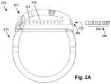
- FIG. 2Ais a schematic view of one embodiment of the control module of FIG. 1 configured and arranged to electrically couple to an elongated device, according to the invention
- FIG. 2Bis a schematic view of one embodiment of a lead extension configured and arranged to electrically couple the elongated device of FIG. 2A to the control module of FIG. 1 , according to the invention;
- FIG. 3Ais a schematic perspective view of a distal end portion of a lead that includes a stimulation cuff, according to the invention.
- FIG. 3Bis a schematic, perspective close-up view of the cuff of FIG. 3A , according to the invention.
- FIG. 3Cis a side elevational view of the cuff of FIG. 3B , according to the invention.
- FIG. 3Dis a cross-sectional view of the cuff of FIG. 3B taken along line 3 D- 3 D, according to the invention.
- FIG. 4is a schematic overview of one embodiment of components of an electrical stimulation arrangement, according to the invention.
- FIG. 5is a schematic overview of one embodiment of components of a system for selection of stimulation parameters, according to the invention.
- FIG. 6is a schematic flowchart of one embodiment of a method for selection of stimulation parameters, according to the invention.
- FIG. 7is a schematic cross-sectional view of one embodiment of a cuff lead, according to the invention.
- FIG. 8is a schematic diagram of one embodiment of an interface for performing at least a portion of method of selecting stimulation parameters, according to the invention
- FIG. 9is a schematic diagram of one embodiment of an interface to assist in a method of selecting stimulation parameters, according to the invention.
- FIG. 10is a schematic diagram of one embodiment of another interface to assist in a method of selecting stimulation parameters, according to the invention.
- the present inventionis directed to the area of implantable electrical stimulation systems and methods of making and using the systems.
- the present inventionis also directed to methods and systems for selecting stimulation parameters for implantable electrical stimulation cuff devices.
- Suitable implantable electrical stimulation systemsinclude, but are not limited to, a least one lead with one or more electrodes disposed along a distal end of the lead.
- Leadsinclude, for example, percutaneous leads, paddle leads, and cuff leads. Examples of electrical stimulation systems with leads are found in, for example, U.S. Pat. Nos.
- 2007/01500362009/0187222; 2009/0276021; 2010/0076535; 2010/0268298; 2011/0004267; 2011/0078900; 2011/0130817; 2011/0130818; 2011/0238129; 2011/0313500; 2012/0016378; 2012/0046710; 2012/0071949; 2012/0165911; 2012/0197375; 2012/0203316; 2012/0203320; 2012/0203321; 2012/0316615; and 2013/0105071; and U.S. patent application Ser. Nos. 12/177,823 and 13/750,725, all of which are incorporated by reference in their entireties.
- a cuff leadfor peripheral nerve stimulation. It will be understood, however, that other leads can be used including, but not limited to, percutaneous and directional leads and paddle leads. It will also be understood that the leads, systems, and methods described herein can also be used for other types of stimulation including, but not limited to, spinal cord stimulation, deep brain stimulation, dorsal root ganglion stimulation, and stimulation of other nerves, organs, or tissues.
- FIG. 1illustrates schematically one embodiment of an electrical stimulation system 100 .
- the electrical stimulation systemincludes a control module (e.g., a stimulator or pulse generator) 102 and a lead 103 coupleable to the control module 102 .
- the lead 103includes a distal end portion 105 , shown schematically, but will be described in detail below (e.g., a distal end portion 300 in FIGS. 3A-3D .)
- the lead 103includes one or more lead bodies 106 , an array of electrodes 133 , such as electrode 134 , and an array of terminals (e.g., 210 in FIG. 2A-2B ) disposed along the one or more lead bodies 106 .
- the leadis isodiametric along a longitudinal length of the lead body 106 .
- the lead 103can be coupled to the control module 102 in any suitable manner. In at least some embodiments, the lead 103 couples directly to the control module 102 . In at least some other embodiments, the lead 103 couples to the control module 102 via one or more intermediate devices ( 200 in FIGS. 2A-2B ). For example, in at least some embodiments one or more lead extensions 224 (see e.g., FIG. 2B ) can be disposed between the lead 103 and the control module 102 to extend the distance between the lead 103 and the control module 102 . Other intermediate devices may be used in addition to, or in lieu of, one or more lead extensions including, for example, a splitter, an adaptor, or the like or combinations thereof. It will be understood that, in the case where the electrical stimulation system 100 includes multiple elongated devices disposed between the lead 103 and the control module 102 , the intermediate devices may be configured into any suitable arrangement.
- the control module 102typically includes a connector housing 112 and a sealed electronics housing 114 . Stimulation circuitry 110 and an optional power source 120 are disposed in the electronics housing 114 . A control module connector 144 is disposed in the connector housing 112 . The control module connector 144 is configured and arranged to make an electrical connection between the lead 103 and the stimulation circuitry 110 of the control module 102 .
- the electrical stimulation system or components of the electrical stimulation systemare typically implanted into the body of a patient.
- the electrical stimulation systemcan be used for a variety of applications including, but not limited to, brain stimulation, neural stimulation, spinal cord stimulation, muscle stimulation, and the like.
- the electrodes 134can be formed using any conductive, biocompatible material. Examples of suitable materials include metals, alloys, conductive polymers, conductive carbon, and the like, as well as combinations thereof. In at least some embodiments, one or more of the electrodes 134 are formed from one or more of: platinum, platinum iridium, palladium, palladium rhodium, or titanium.
- the number of electrodes 134 in each array 133may vary. For example, there can be two, four, six, eight, ten, twelve, fourteen, sixteen, or more electrodes 134 . As will be recognized, other numbers of electrodes 134 may also be used.
- the electrodes of the lead body 106are typically disposed in, or separated by, a non-conductive, biocompatible material such as, for example, silicone, polyurethane, polyetheretherketone (“PEEK”), epoxy, and the like or combinations thereof.
- the lead body 106may be formed in the desired shape by any process including, for example, molding (including injection molding), casting, and the like.
- the non-conductive materialtypically extends from the distal end of the lead body 106 to the proximal end of the lead body 106 .
- Terminalsare typically disposed along the proximal end of the lead body 106 of the electrical stimulation system 100 (as well as any splitters, lead extensions, adaptors, or the like) for electrical connection to corresponding connector contacts (e.g., 214 and 240 in FIG. 2B ).
- the connector contactsare disposed in connectors (e.g., 144 in FIGS. 1-2B ; and 222 in FIG. 2B ) which, in turn, are disposed on, for example, the control module 102 (or a lead extension, a splitter, an adaptor, or the like).
- Electrically conductive wires, cables, or the likeextend from the terminals to the electrodes 134 .
- one or more electrodes 134are electrically coupled to each terminal. In at least some embodiments, each terminal is only connected to one electrode 134 .
- the electrically conductive wiresmay be embedded in the non-conductive material of the lead body 106 or can be disposed in one or more lumens (not shown) extending along the lead body 106 . In some embodiments, there is an individual lumen for each conductor. In other embodiments, two or more conductors extend through a lumen. There may also be one or more lumens (not shown) that open at, or near, the proximal end of the lead body 106 , for example, for inserting a stylet to facilitate placement of the lead body 106 within a body of a patient.
- the one or more lumensmay be flushed continually, or on a regular basis, with saline, cerebrospinal fluid, or the like.
- the one or more lumensare permanently or removably sealable at the distal end.
- FIG. 2Ais a schematic side view of one embodiment of a proximal end of one or more elongated devices 200 configured and arranged for coupling to one embodiment of the control module connector 144 .
- the one or more elongated devicesmay include, for example, the lead body 106 , one or more intermediate devices (e.g., the lead extension 224 of FIG. 2B , an adaptor, or the like or combinations thereof), or a combination thereof.
- the control module connector 144defines at least one port into which a proximal end of the elongated device 200 can be inserted, as shown by directional arrow 212 .
- the connector housing 112is shown having one port 204 .
- the connector housing 112can define any suitable number of ports including, for example, one, two, three, four, five, six, seven, eight, or more ports.
- the control module connector 144also includes a plurality of connector contacts, such as connector contact 214 , disposed within each port 204 .
- the connector contacts 214can be aligned with a plurality of terminals 210 disposed along the proximal end(s) of the elongated device(s) 200 to electrically couple the control module 102 to the electrodes ( 134 of FIG. 1 ) disposed at a distal end of the lead 103 .
- Examples of connectors in control modulesare found in, for example, U.S. Pat. Nos. 7,244,150 and 8,224,450, which are incorporated by reference.
- FIG. 2Bis a schematic side view of another embodiment of the electrical stimulation system 100 .
- the electrical stimulation system 100includes a lead extension 224 that is configured and arranged to couple one or more elongated devices 200 (e.g., the lead body 106 , an adaptor, another lead extension, or the like or combinations thereof) to the control module 102 .
- the lead extension 224is shown coupled to a single port 204 defined in the control module connector 144 .
- the lead extension 224is shown configured and arranged to couple to a single elongated device 200 .
- the lead extension 224is configured and arranged to couple to multiple ports 204 defined in the control module connector 144 , or to receive multiple elongated devices 200 , or both.
- a lead extension connector 222is disposed on the lead extension 224 .
- the lead extension connector 222is shown disposed at a distal end 226 of the lead extension 224 .
- the lead extension connector 222includes a connector housing 228 .
- the connector housing 228defines at least one port 230 into which terminals 210 of the elongated device 200 can be inserted, as shown by directional arrow 238 .
- the connector housing 228also includes a plurality of connector contacts, such as connector contact 240 .
- the connector contacts 240 disposed in the connector housing 228can be aligned with the terminals 210 of the elongated device 200 to electrically couple the lead extension 224 to the electrodes ( 134 of FIG. 1 ) disposed along the lead ( 103 in FIG. 1 ).
- the proximal end of the lead extension 224is similarly configured and arranged as a proximal end of the lead 103 (or other elongated device 200 ).
- the lead extension 224may include a plurality of electrically conductive wires (not shown) that electrically couple the connector contacts 240 to a proximal end 248 of the lead extension 224 that is opposite to the distal end 226 .
- the conductive wires disposed in the lead extension 224can be electrically coupled to a plurality of terminals (not shown) disposed along the proximal end 248 of the lead extension 224 .
- the proximal end 248 of the lead extension 224is configured and arranged for insertion into a connector disposed in another lead extension (or another intermediate device). In other embodiments (and as shown in FIG. 2B ), the proximal end 248 of the lead extension 224 is configured and arranged for insertion into the control module connector 144 .
- a large control modulesuch as the control module 102 illustrated in FIGS. 1-2B , is not desirable.
- a smaller, more compact control modulemay be suitable for situations such as, for example, short-term implantation (for example, 1 or 2 weeks, 1, 2, 3, 4, 6, 8, 12, or 18 months), short-term trial (for example, 1 or 2 weeks, 1, 2, 3, 4, 6, 8, 12, or 18 months), clinical studies (for example, for a period of 1 or 2 weeks, 1, 2, 3, 4, 6, 8, 12, or 18 months), or the like.
- Such a control modulemay also be useful when a less invasive surgical implantation is desired, recommended, or required. In some instances, a patient or clinician may be willing to charge the control module more frequently if the control module is smaller or the surgery is less invasive.
- the electrical stimulation system with the smaller control modulecan be upgraded to an electrical stimulation system such as that illustrated in FIGS. 1-2B if the trial shows sufficient benefit to the patient.
- the smaller control modulemay allow for the device to be Mill (magnetic resonance imaging) conditionally safe because of its implant location and size.
- control modulecan be made smaller by permanently affixing the lead (or a lead extension) to the control module.
- the leadcan be hardwired to the stimulation circuitry so that the control module does not need a connector and header.
- FIG. 3Aillustrates, schematically, a distal end portion 305 of the lead 103 ( FIG. 1 ) that includes a cuff 350 with a cuff body 354 , a mount 352 and a lead body 306 according to an embodiment of the present invention.
- the lead body 306can be, for example, structurally the same or similar to the lead body 106 ( FIG. 1 ), operates in a same or similar manner, and may be manufactured in accordance with one or more of the methods disclosed in U.S. Patent Application No. 2007/0150036, which is hereby incorporated by reference in its entirety, or in accordance with other methods or references cited herein.
- the cuff 350permits stimulation of a target nerve (not shown), for example a peripheral nerve located in soft tissue, and may be small in diameter.
- the cuff 350can operate to provide vagus or sympathetic nerve stimulation.
- the cuff 350may advantageously permit an easier implantation around the target nerve than conventional cuff leads that wrap helically around the target nerve.
- the cuff 350may also permit selective stimulation of different regions of the target nerve.
- the number of electrodes 334 as well as the arrangement of the electrodes 334can vary depending on the type of nerve being stimulated, a region of the nerve being stimulated, or any combination thereof.
- the electrodes 334can be formed using any conductive, biocompatible material. Examples of suitable materials include metals, alloys, conductive polymers, conductive carbon, and the like, as well as combinations thereof. In at least some embodiments, one or more of the electrodes 334 are formed from one or more of: platinum, platinum iridium, palladium, palladium rhodium, or titanium.
- the electrodes 334may take the form of segmented electrodes, have a variety of shapes such as, but not limited to, a concave, convex or otherwise curved shape, a box shape, a dish or parabolic shape, or any combination thereof. In at least some embodiments, the electrodes 334 may take the form of segmented electrodes having a shape complementary to a body or carrier onto which they are disposed.
- any suitable number of electrodes 334can be disposed on the cuff body 354 including, for example, four, five, six, seven, eight, nine, ten, eleven, twelve, fourteen, sixteen, twenty-four, thirty-two, or more electrodes 334 .
- the electrodes 334may be arranged into columns or rows. In at least some embodiments, one column includes four electrodes 334 .
- the arrangement of the electrode(s) 334may vary.
- the electrodes 334may be arranged in two or more parallel columns where such columns can be aligned or staggered from one another, or in any other desired column or row arrangement.
- the electrodesmay also be arranged, for example, in a row, or “in line,” along the longitudinal axis of a small diameter lead body.
- the electrodesmay be placed linearly, circularly, or elliptically.
- the arrangement of electrodesmay be symmetrical or asymmetrical. As will be recognized, other arrangements of electrodes are also possible.
- the electrodes 334can be disposed on the cuff body 354 in any suitable arrangement. In at least some embodiments, an inward facing surface of the electrode 334 is flush with an inner surface of the cuff body 354 . In yet other embodiments, the inward facing surface of the electrode 334 is recessed relative to the inner surface of the cuff body 354 .
- the lead body 306 , cuff body 354 and the mount 352can be made from a non-conductive, biocompatible material such as, for example, silicone, polyurethane, polyetheretherketone (“PEEK”), epoxy, and the like or combinations thereof.
- the lead body 306 and the cuff body 354may be formed in the desired shape by any process including, for example, molding (including injection molding), casting, and the like.
- the cuff body 354is made from silicone with electrodes 334 disposed in the silicone cuff body 354 .
- the cuff 350may be manufactured by molding the electrodes 334 into the cuff body 354 while allowing for electrode alignment.
- the electrodes 334are molded into a thin, silicone carrier that allows for electrode alignment.
- conductors (not shown) from the lead body 306are connected (e.g., welded) to a backside of the electrodes 334 .
- the carrieris wrapped around a pin or rod and then overmolded into the cuff body 354 .
- the conductors (not shown) from within the lead body 306are received in the mount 352 , which in turn is attached to the cuff body 354 such that each conductor passes through the mount 352 for a direct electrical connection with one of the electrodes 334 (e.g., one conductor is electrically connected with one electrode and so on).
- the mount 352may be attached using a variety of means such as, but not limited to, molding or adhering the mount 352 to the cuff body 354 .
- the conductors from within the lead body 306are electrically coupled to the electrodes 334 using jumper, intermediate or transition wires from the lead body 306 to the electrodes 334 .
- FIGS. 3B-3Dshow the cuff 350 having the plurality of electrodes 334 disposed on an inner surface 356 of the cuff body 354 .
- the cuff body 354takes the form of a C-shaped cuff having the inner surface 356 , an outer surface 358 , and a longitudinal opening 360 that extends through both the outer surface 358 and inner surface 356 of the cuff body 354 .
- formation of the cuff 350 into the “C-shape”can include the steps of wrapping and overmolding to form the cuff body 354 in which the inner surface 356 defines a nerve channel 362 (best seen in FIG. 3D ).
- the opening 360is manipulated or initially sized to allow the target nerve (not shown) to be slipped, inserted, fed or otherwise received into nerve channel 362 of the cuff 350 such that the cuff 350 wraps around the target nerve.
- the opening 360allows the cuff 350 to be easily moved over and around the target nerve or relative to the target nerve whether rotationally or transitionally.
- the cuff 350may be rotated, translated or otherwise repositioned, if needed, along a target nerve axis 470 ( FIG. 4B ) that is parallel to or approximately parallel to a longitudinal axis of the nerve channel 362 . Repositioning of the cuff 350 may permit intimate or selected stimulation between a particular region of the target nerve and one or more of the electrodes 334 .
- the edges of the cuff body 354 defining the opening 360can be sutured to capture the target nerve without undesirably compressing the target nerve.
- suture holes 364are optionally incorporated into the edges of the cuff 350 to allow for closing or partially closing the cuff 350 around the target nerve.
- the suture holes 364can be used as points of manipulation or tool attachment during implantation (e.g., using forceps or an equivalent tool).
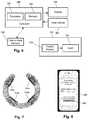
- FIG. 4is a schematic overview of one embodiment of components of an electrical stimulation arrangement 404 that includes an electrical stimulation system 400 with a lead 402 , stimulation circuitry 406 , a power source 408 , and an antenna 410 .
- the electrical stimulation systemcan be, for example, any of the electrical stimulation systems described above. It will be understood that the electrical stimulation arrangement can include more, fewer, or different components and can have a variety of different configurations including those configurations disclosed in the stimulator references cited herein.
- the power source 408is a rechargeable battery or chargeable capacitor
- the power sourcemay be recharged/charged using the antenna 410 , if desired.
- Powercan be provided for recharging/charging by inductively coupling the power source 408 through the antenna 410 to a recharging unit 436 external to the user. Examples of such arrangements can be found in the references identified above.
- electrical currentis emitted by the electrodes (such as electrodes 134 in FIG. 1 ) on the lead 402 to stimulate nerve fibers, muscle fibers, or other body tissues near the electrical stimulation system.
- the stimulation circuitry 406can include, among other components, a processor 434 and a receiver 432 .
- the processor 434is generally included to control the timing and electrical characteristics of the electrical stimulation system. For example, the processor 434 can, if desired, control one or more of the timing, frequency, strength, duration, and waveform of the pulses.
- the processor 434can select which electrodes can be used to provide stimulation, if desired. In some embodiments, the processor 434 selects which electrode(s) are cathodes and which electrode(s) are anodes. In some embodiments, the processor 434 is used to identify which electrodes provide the most useful stimulation of the desired tissue.
- Any processorcan be used and can be as simple as an electronic device that, for example, produces pulses at a regular interval or the processor can be capable of receiving and interpreting instructions from an external programming unit 438 that, for example, allows modification of pulse characteristics.
- the processor 434is coupled to a receiver 432 which, in turn, is coupled to the antenna 410 . This allows the processor 434 to receive instructions from an external source to, for example, direct the pulse characteristics and the selection of electrodes, if desired.
- the antenna 410is capable of receiving signals (e.g., RF signals) from an external telemetry unit 440 that is programmed by the programming unit 438 .
- the programming unit 438can be external to, or part of, the telemetry unit 440 .
- the telemetry unit 440can be a device that is worn on the skin of the user or can be carried by the user and can have a form similar to a pager, cellular phone, or remote control, if desired.
- the telemetry unit 440may not be worn or carried by the user but may only be available at a home station or at a clinician's office.
- the programming unit 438can be any unit that can provide information to the telemetry unit 440 for transmission to the electrical stimulation system 400 .
- the programming unit 438can be part of the telemetry unit 440 or can provide signals or information to the telemetry unit 440 via a wireless or wired connection.
- One example of a suitable programming unitis a computer operated by the user or clinician to send signals to the telemetry unit 440 .
- the signals sent to the processor 434 via the antenna 410 and the receiver 432can be used to modify or otherwise direct the operation of the electrical stimulation system 400 .
- the signalsmay be used to modify the pulses of the electrical stimulation system such as modifying one or more of pulse duration, pulse frequency, pulse waveform, and pulse strength.
- the signalsmay also direct the electrical stimulation system 400 to cease operation, to start operation, to start charging the battery, or to stop charging the battery.
- the electrical stimulation system 400may include a transmitter (not shown) coupled to the processor 434 and the antenna 410 for transmitting signals back to the telemetry unit 440 or another unit capable of receiving the signals.
- the electrical stimulation system 400may transmit signals indicating whether the electrical stimulation system 400 is operating properly or not or indicating when the battery needs to be charged or the level of charge remaining in the battery.
- the processor 434may also be capable of transmitting information about the pulse characteristics so that a user or clinician can determine or verify the characteristics.
- Multi-electrode leadsmay enable greater selectivity of nerve fibers which may be modulated, for example, by using current steering to target areas of nerve bundles. Although multi-electrode leads may provide improved therapy, there can be a challenge in determining which electrodes and stimulation parameters provide therapeutic benefit while reducing or eliminating side effects.
- a treating physicianmay wish to tailor the stimulation parameters (such as which one or more of the stimulating electrode contacts to use, the stimulation pulse amplitude (such as current or voltage amplitude depending on the stimulator being used,) the stimulation pulse width, the stimulation frequency, the duty cycle, the stimulation phase, or the like or any combination thereof) for a particular patient to improve the effectiveness of the therapy.
- stimulation parameterssuch as which one or more of the stimulating electrode contacts to use, the stimulation pulse amplitude (such as current or voltage amplitude depending on the stimulator being used,) the stimulation pulse width, the stimulation frequency, the duty cycle, the stimulation phase, or the like or any combination thereof
- Examples of stimulation parameters to achieve a particular therapeutic effect or to block a particular side effectcan be found in, for example, U.S. Patent Application Publication No. 2015/0202446, incorporated herein by reference, as well as other references cited herein.
- Electrical stimulation systemscan provide an interface that facilitates testing of different sets of stimulation parameters to facilitate parameter selection.
- a programmer or clinicianseeks to provide more effective stimulation while reducing or avoiding side effects. Methods and systems for identifying stimulation parameters to achieve these objectives are described herein.
- FIG. 5illustrates one embodiment of a system for practicing the invention.
- the systemcan include a computer 500 or any other similar device that includes a processor 502 and a memory 504 , a display 506 , an input device 508 , the electrical stimulation system 512 , and, optionally, one or more sensors 518 (which may be independent of the electrical stimulation system or part of the electrical stimulation system).
- the computer 500can be a laptop computer, desktop computer, tablet, mobile device, smartphone or other devices that can run applications or programs, or any other suitable device for processing information and for presenting a user interface (such as the user interfaces of FIGS. 8, 9, and 10 ).
- the computercan be, for example, a clinician programmer, patient programmer, or remote programmer for the electrical stimulation system 512 .
- the computer 500can be local to the user or can include components that are non-local to the user including one or both of the processor 502 or memory 504 (or portions thereof).
- the usermay operate a terminal that is connected to a non-local computer.
- the memorycan be non-local to the user.
- the computer 500can utilize any suitable processor 502 including one or more hardware processors that may be local to the user or non-local to the user or other components of the computer.
- the processor 502is configured to execute instructions provided to the processor, as described below.
- the memory 504illustrates a type of computer-readable media, namely computer-readable storage media.
- Computer-readable storage mediamay include, but is not limited to, nonvolatile, non-transitory, removable, and non-removable media implemented in any method or technology for storage of information, such as computer readable instructions, data structures, program modules, or other data. Examples of computer-readable storage media include RAM, ROM, EEPROM, flash memory, or other memory technology, CD-ROM, digital versatile disks (“DVD”) or other optical storage, magnetic cassettes, magnetic tape, magnetic disk storage or other magnetic storage devices, or any other medium which can be used to store the desired information and which can be accessed by a computer.
- Communication methodsprovide another type of computer readable media; namely communication media.
- Communication mediatypically embodies computer-readable instructions, data structures, program modules, or other data in a modulated data signal such as a carrier wave, data signal, or other transport mechanism and include any information delivery media.
- modulated data signaland “carrier-wave signal” includes a signal that has one or more of its characteristics set or changed in such a manner as to encode information, instructions, data, and the like, in the signal.
- communication mediaincludes wired media such as twisted pair, coaxial cable, fiber optics, wave guides, and other wired media and wireless media such as acoustic, RF, infrared, and other wireless media.
- the display 506can be any suitable display device, such as a monitor, screen, display, or the like, and can include a printer.
- the input device 508can be, for example, a keyboard, mouse, touch screen, track ball, joystick, voice recognition system, or any combination thereof, or the like and can be used by the user to interact with a user interface or clinical effects map.
- the electrical stimulation system 512can include, for example, a control module 514 (for example, an implantable pulse generator) and a lead 516 .
- the leadcan be any suitable lead for peripheral nerve stimulation including, but not limited to the cuff leads illustrated in FIG. 1 and FIGS. 3A-3D .
- the electrical stimulation system 512may communicate with the computer 500 through a wired or wireless connection or, alternatively or additionally, a user can provide information between the electrical stimulation system 512 and the computer 500 using a computer-readable medium or by some other mechanism.
- the computer 500may include part of the electrical stimulation system.
- the one or more sensors 518can be any suitable sensor for measuring or observing physiological or other responses to the stimulation. In at least some embodiments, at least one of the sensors 518 is external to the electrical stimulation system. In at least some embodiments, at least one of the sensors 518 is part of the electrical stimulation system, for example, a sensor (e.g., an electrode) disposed on the lead 516 or within the control module 514 or a sensor coupled to the control module 514 through another lead or the like.
- a sensore.g., an electrode
- physiological or other responsesinclude, but are not limited to, muscle electrical potentials, nerve action potentials, heart rate, pulmonary function (e.g., respiratory rate, tidal volume, minute ventilation, or the like), heart sounds such as the first heart sound (S 1 ) or the second heart sound (S 2 ), ECG signals (e.g., R-wave height, Q-R interval, P-interval, or the like), heart rate variability, peripheral temperature, blood pressure (e.g., diastolic, systolic, or mean blood pressure), acetylcholine or catecholamine measurements, accelerometer measurements (e.g., to observe epilepsy, Parkinsonism, or tremor), posture, gait, or the like or any combination thereof.
- ECG signalse.g., R-wave height, Q-R interval, P-interval, or the like
- heart rate variabilitye.g., peripheral temperature
- blood pressuree.g., diastolic, systolic, or mean blood pressure
- the present systems and methodscan be used to provide stimulation to any suitable target.
- the present systems and methodsare adapted for stimulating peripheral nerves (e.g., nerves outside of the spinal cord.)
- peripheral nervese.g., nerves outside of the spinal cord.
- vagus nerve stimulationwhich can be used to treat a variety of disorders or diseases including, but not limited to, heart failure, epilepsy, migraine, or inflammatory diseases.
- One possible side-effect of vagus nerve stimulationis laryngeal stimulation.
- Other side effects of peripheral nerve stimulationcan be, for example, pain or discomfort.
- Other types of peripheral nerve stimulationinclude, but are not limited to, stimulation of the trigeminal nerve, sciatic nerve, femoral nerve, or the like.
- Nervescan have complicated anatomy with various fibers and other cells extending along the nerve or portions of the nerve.
- targetssuch as the vagus nerve
- the neuroanatomyis not predictable from patient-to-patient, and not even within a patient along the length of the nerve.
- Orientation of nerve fiberscan change significantly longitudinally along the length of the nerve. Therefore, it may be difficult to accurately predict the effects of stimulation using a multi-electrode lead, such as those described above.
- An advantage of using such multi-electrode leadsis that they may be capable of stimulating efficacious regions of the nerve while avoiding, at least in part, regions that produce side effects.
- a multi-electrode lead with multiple independent current controloffers the capability to target specific locations within a structure (for example, to target nerve fibers contributing to a cardiac effect.
- a challengeis determining where to target current in a peripheral nerve to avoid or reduce the side effects and maintain or improve efficacy of the stimulation therapy.
- the present systems and methodsare useful for identifying electrodes and stimulation parameters of such complicated and unpredictable anatomy and response.
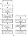
- FIG. 6illustrates an embodiment of a method for selecting stimulation parameters for peripheral nerve electrical stimulation. It will be understood that such methods may also be useful for selecting stimulation parameters for other types of electrical stimulation.
- the leadis implanted adjacent or around a peripheral nerve and allowed to stabilize. The stabilization period may be, for example, a few hours or days.
- an initial set of different electrode combinationsare tested to identify locations on the peripheral nerve that, when stimulated, produce beneficial stimulation effects or side effects.
- the electrode combinationincludes an electrode pair; however, other embodiments may include three, four, or more electrodes in each electrode combination.
- the number of electrodes in each electrode combinationcan be the same or can be different.
- the individual electrodes of the electrode combinationcan be designated as anodes or cathodes.
- the electrodes of the electrode combinationcan all be anodes or can all be cathodes with the case of the control module acting as the cathode or anode, respectively.
- the testingincludes receiving or determining, as testing results, one or more values indicative of electrical stimulation using the electrode combination.
- the valuescan be numerical or other quantitative values or can be alphanumeric qualitative values or can be simply an indication that the particular stimulation is acceptable or not.
- particular electrodes pairs from the initial setcan be identified as indicating regions of the nerve that should be investigated further.
- beneficial stimulation effect thresholdsfor example, when a beneficial stimulation effect is observed or reaches a threshold level
- side effect thresholdsfor example, when a side effect is observed or reaches a threshold level
- both for the electrode combinationscan be determined.
- the electrode combinationsare tested to determine at what stimulation amplitude a side effect manifests or reaches a threshold level (which may be quantitative or subjective.)
- the objective of this initial set of electrode combinationsis to provide a high-level initial mapping of the nerve response and nerve structure that can be refined is later steps.
- a cross-section of one embodiment of a cuff leadis provided in FIG. 7 with four identified electrodes 334 a , 334 b , 334 c , 334 d .
- This cross-sectionrepresents one set of electrodes at a particular position along the cuff lead.
- the cuff lead 306includes four sets of electrodes at four different positions along the cuff lead.
- the initial set of different electrodescan be each pair of adjacent electrodes. For the lead and set of electrodes in FIG.
- the initial set of electrode combinationscan include electrode pairs containing electrodes that are of different sets, but are adjacent to each other. Any other suitable selection of the initial set of electrode combinations can be used; those selections presented in this paragraph are non-limiting examples.
- Electrodes combinationscan be made. For example, only electrode combinations at two of the positions along the cuff lead 306 might be tested.
- the selection of electrode combinations for the initial setmay be pre-programmed for an electrical stimulation system or may be selectable by a clinician, user, or other individual (although there may also be a default set of electrode combinations that can be modified.)
- the initial set of electrode combinationsis selected or pre-programmed so that each electrode of the lead is part of no more than one or two of the electrode combinations.
- each electrode combinationis tested with one electrode acting as the anode and the other electrode acting as the cathode.
- the electrode combinationmay be tested at different stimulation amplitudes.
- the stimulation amplitudemay be stepped up from an initial value by regular (or irregular) increments.
- the presence or absence (and, optionally, quantitative or subjective level) of a beneficial stimulation effect, side effect(s), or bothmay be determined. The determination may be made using one or more sensors, user (e.g., patient or clinician) feedback, clinician or programmer observation, or any combination thereof or any other mechanism for detecting beneficial stimulation effects or side effects.
- the stimulation amplitudeis increased until a stop criterion is met.
- stop criteriainclude, but are not limited to, a side effect is observed, the beneficial impact of the therapy has plateaued, a tolerance is reached or exceeded, a stimulation amplitude maximum is reached, or a patient, clinician, or programmer determines to halt the increase of stimulation amplitude, or any combination of these criteria.
- a systemmay include all or only some of these criteria.
- FIG. 8illustrates one embodiment of a relatively simple interface 880 that can be used to test the initial set of electrode combinations.
- a relatively simple interface 880that can be used to test the initial set of electrode combinations.
- such an interfacemay be suitable for use by the patient with or without a clinician guiding the process.
- each of the electrode combinations(twenty electrode combinations in the illustrated example) is sequentially tested with the stimulation amplitude increasing incrementally.
- the usertaps the button 882 when the therapy becomes uncomfortable (e.g., produces a discomfort side effect above a subjective threshold.) Once that occurs (or if the stimulation amplitude reaches a maximum stimulation amplitude without the user tapping the button 882 ), the system continues to the next electrode combination until all of the electrode combinations have been tested.
- the testing of each electrode combinationproceeds automatically and the system moves from one electrode combination to the next automatically.
- the usermay have the option to halt or pause the system.
- the usercan direct the individual testing of electrode combinations.
- the usermay be allowed to skip electrode combinations.
- FIG. 9illustrates one embodiment of an interface that can present the results of the testing.
- the sixteen electrodesare identified as L 1 -L 8 and R 1 -R 8 .
- the sixteen electrodescan correspond to, for example, the sixteen electrodes on the cuff lead 305 of FIGS. 3A-3D .
- the side effect threshold valuesare reported in the other boxes (ranging in this example from 0.1 to 1.7 mA).
- the boxes to the left of L 1 -L 4correspond to the electrode combination of L 1 -L 4 with R 1 -R 4 respectively.
- the other result boxesare disposed between the two electrodes of the pair. It will be understood that values other than side effect threshold values may be determined and illustrated or that multiple values for each pair may be determined and illustrated.
- determined values that meet threshold criteriaare indicated.
- the boxes containing values that meet threshold criteriamay be colored (for example, colored green) or shaded differently than those that do not, as illustrated in FIG. 9 .
- Other visual indicationsmay be used instead of, or in addition to, coloring or shading.
- the corresponding electrodes that produced the valuesmay also be indicated by different coloring or shading or any other suitable visual indication.
- the boxes with values from 0.7-1.7 mAare indicated because they meet a threshold criterion of achieving at least 0.5 mA prior to reaching an intolerable level of a side effect.
- the electrode combinations 1) L 5 /R 5 ; 2) L 2 /R 2 ; and 3) L 3 /R 3appear to indicate the best regions to continue testing.
- the systemautomatically determines which electrode combinations to use in the succeeding step.
- the usermay be allowed to modify the selection of electrode combinations to add or remove selected electrode combinations.
- the usermay be directed to select electrode combinations to use in the succeeding steps.
- step 604can be performed relatively quickly such as, for example, within 10, 15, 20, 30, 45, or 60 minutes or more.
- step 604may be performed solely by the patient using a patient programmer or an application on a mobile device, such as a mobile phone, tablet, or laptop computer.
- each of the additional electrode combinationsincludes at least one of the electrodes of one of the electrode combinations selected in step 604 .
- the systemautomatically determines which additional electrode combinations to test.
- the usermay be allowed to modify the selection of electrode combinations to add or remove selected electrode combinations.
- the usermay be directed to select the additional electrode combinations.
- the testingincludes receiving or determining, as testing results, one or more values indicative of electrical stimulation using the electrode combination.
- the valuescan be numerical or other quantitative values or can be alphanumeric qualitative values or can be simply an indication that the particular stimulation is acceptable or not.
- FIG. 10illustrates an interface with the results of testing these electrode combinations.
- electrode combinations around 1) L 5 /R 5 and 2) L 2 /R 2have been tested.
- the results to the left of L 2correspond to pairs of R 1 -R 3 , respectively, from top to bottom.
- the testing of each electrode combination in step 606is similar or the same as the testing in step 604 .
- the testing of each electrode combination in step 606may include the testing performed in step 604 and also include a longer period of stimulation to observe any longer term or slower developing beneficial stimulation effects or side effects.
- one or more physiological responsescan be monitored or observed.
- a duty cyclemay be employed (for example, 20 seconds of stimulation followed by 40 seconds of no stimulation) during the stimulation time. In some embodiments, different duty cycles can be tested.
- the testing in step 606may be performed over the course of minutes, hours, days, or weeks.
- one or more of the tested electrode combinationsare selected for further testing.
- the selection of the electrode combinationsmay be based on any suitable criterion or set of criteria.
- a set of criteriamay include a) a maximum stimulation amplitude at which stimulation is tolerable (e.g., side effects are tolerable at the maximum stimulation amplitude); b) a minimum amount of beneficial stimulation effect (e.g., at least a threshold amount of beneficial stimulation effect at a tolerable stimulation amplitude); and c) a ratio of desired beneficial stimulation effect to undesired side effect at one or more stimulation amplitudes.
- the systemautomatically determines which electrode combinations to use in the succeeding step.
- the usermay be allowed to modify the selection of electrode combinations to add or remove selected electrode combinations.
- the usermay be directed to select electrode combinations to use in the succeeding steps.
- the stimulation parametersare varied for the electrode combinations selected in step 606 to determine the results of different sets of stimulation parameters.
- stimulation parametersinclude, but are not limited to, stimulation amplitude, pulse frequency, pulse duration, duty cycle, pulse waveform, electrode polarity (e.g., which electrode is the anode and which is the cathode), burst frequency (where the pulses are delivered in bursts of pulses followed by a period of no pulses), or the like or any combination thereof.
- the testing in step 608may be performed over the course of minutes, hours, days, or weeks.
- stimulation parameterse.g., stimulation amplitude, stimulation frequency, pulse width, duty cycle, pulse waveform, or the like or any combination thereof
- stimulation parameters for one electrode of an electrode paircan be held constant while the stimulation parameters for the other electrode are varied.
- the stimulation parameters for the first electrodecan be varied while the stimulation parameters for the second can be held constant (for example, at a predetermined set of parameters or at a selected set of parameters based on the previous sweep of stimulation parameters).
- the testingmay include switching polarities of the electrodes.
- the testingincludes receiving or determining, as testing results, one or more values indicative of electrical stimulation using the electrode combination.
- the valuescan be numerical or other quantitative values or can be alphanumeric qualitative values or can be simply an indication that the particular stimulation is acceptable or not.
- one or more electrode combinations and one or more corresponding sets of stimulation parametersare then selected for further testing.
- the selectionmay be based on the use of a suitable (or even best) set of stimulation parameters for the individual electrode combinations.
- the selection of the electrode combinationsmay be based on any suitable criterion or set of criteria.
- a set of criteriamay include a) a maximum stimulation amplitude at which stimulation is tolerable (e.g., side effects are tolerable at the maximum stimulation amplitude); b) a minimum amount of beneficial stimulation effect (e.g., at least a threshold amount of beneficial stimulation effect at a tolerable stimulation amplitude); and c) a ratio of desired beneficial stimulation effect to undesired side effect at one or more stimulation amplitudes.
- selection criteriamay also include consideration of the other stimulation parameters that were tested and whether those stimulation parameters would be suitable for long term stimulation of the patient.
- the systemautomatically determines which electrode combinations to use in the succeeding step.
- the usermay be allowed to modify the selection of electrode combinations to add or remove selected electrode combinations.
- the usermay be directed to select electrode combinations to use in the succeeding steps.
- the results for selected electrode combination(s) from step 608can then be used to expand beyond just pairs of electrodes to test groups of electrodes for delivery of electrical stimulation.
- the group of electrodesmay contain two, three, four or more electrodes where, for example, one or more electrodes act as anodes and one or more electrodes act as cathodes.
- the anodic or cathodic currentcould be distributed between two or more electrodes where the division between electrodes can be equal (e.g., 50% on each) or unequal (e.g., split 10%/90%; 20%/80%; 33%/67%; 33%/33%/33%; or any other arrangement.)
- one arrangement of electrodesincludes 100% of the cathodic current on L 5 , 60% of the anodic current on R 5 ; 35% of the anodic current on L 1 ; and 5% of the anodic current on L 6 .
- Such an arrangementwill localize the cathodic stimulation near electrode L 5 with the anodic electrodes R 5 , L 1 , and L 6 guarding the cathode and resisting spread of stimulation from that locale.
- the case of the control modulemay also be used as an electrode.
- the distribution of current between the electrodesmay be based on the relative beneficial stimulation effect evoked at those electrodes, or the side effects evoked at those electrodes, or both.
- any number of multiple electrode groupscan be tested in step 610 .
- the testing in step 610may be performed over the course of minutes, hours, days, or weeks.
- the testingincludes receiving or determining, as testing results, one or more values indicative of electrical stimulation using the electrode group.
- the valuescan be numerical or other quantitative values or can be alphanumeric qualitative values or can be simply an indication that the particular stimulation is acceptable or not.
- One or more the tested electrode groupsare selected to continue.
- the selection of the one or more multiple electrode groupsmay be based on any suitable criterion or set of criteria.
- a set of criteriamay include a) a maximum stimulation amplitude at which stimulation is tolerable (e.g., side effects are tolerable at the maximum stimulation amplitude); b) a minimum amount of beneficial stimulation effect (e.g., at least a threshold amount of beneficial stimulation effect at a tolerable stimulation amplitude); and c) a ratio of desired beneficial stimulation effect to undesired side effect at one or more stimulation amplitudes.
- the stimulation parametersare varied for the one or more multiple electrode groups selected in step 610 to determine the results of different sets of stimulation parameters.
- stimulation parametersinclude, but are not limited to, stimulation amplitude, pulse frequency, pulse duration, duty cycle, pulse waveform, electrode polarity (e.g., which electrode is the anode and which is the cathode), burst frequency (where the pulses are delivered in bursts of pulses followed by a period of no pulses), or the like or any combination thereof.
- the testing in step 608may be performed over the course of minutes, hours, days, or weeks.
- the testingincludes receiving or determining, as testing results, one or more values indicative of electrical stimulation using the electrode group.
- the valuescan be numerical or other quantitative values or can be alphanumeric qualitative values or can be simply an indication that the particular stimulation is acceptable or not.
- step 614one or more multiple electrode groups and one or more corresponding sets of stimulation parameters are then selected for patient stimulation based on the testing in step 612 .
- step 616the set of stimulation parameters and selection of electrodes for each of the one or more multiple electrode groups is transmitted or otherwise communicated to the control unit.
- step 618the patient is stimulated using the stimulation parameters and selection of electrodes for at least one of the one or more multiple electrode groups.
- portions of the method illustrated in FIG. 6can be repeated later to modify or enhance the electrical stimulation.
- steps 612 to 618may be repeated at regular or irregular intervals to further modify the stimulation parameters.
- the nerve or other tissue affected by stimulationmay change over time so that modification of the stimulation parameters or electrode choice or both may enhance stimulation.
- the stepsmay be part of a closed loop feedback system including the control module and sensors and, optionally, the programming unit to continue to modify the stimulation parameters and selection of electrodes over time.
- the nerve or other tissue affected by stimulationmay change with a change in patient posture.
- the steps 612 to 618(or steps 606 to 618 or steps 604 to 618 ) may be repeated separately while the patient is in different postures to derive a posture-specific stimulation configuration for each posture.
- a particular stimulation configurationcan then be applied by the control module at any given instance based on a detected patient posture.
- a set of stimulation parameterscan be referred to as a stimulation configuration or stimulation program.
- different stimulation configurationsmay be determined for multiple, different physical states based on, for example, level of activity, type of activity, or the like.
- the physical statemay be detected using any of the sensors described above or may be manually selected by the patient or other individual.
- a physical statemay be determined based on type of gait, heart rate, respiration, or the like or any combination thereof.
- different stimulation configurationscan be determined for different levels of patient symptoms or conditions (for example, different levels of pain).
- one stimulation configurationcan be determined for little or no pain (for example, this stimulation configuration may be light stimulation or no stimulation at all), another stimulation configuration for moderate pain (for example, a stimulation configuration that produces a beneficial stimulation effect with little or no side effects), and a third stimulation configuration for higher levels of pain (for example, a stimulation configuration that increases the beneficial stimulation effect despite an increase in one or more side effects).
- the patient symptom or conditionmay be detected using any of the sensors described above or may be manually selected by the patient or other individual.
- the selection of electrode combinations or electrode groupsmay be performed manually or automatically.
- machine learningmay be used on a system to first train the system to perform the selection using known or user-guided selections and then to allow the system to perform the selections in view of the paradigm created by machine learning.
- the process of steps 604 - 614may be repeated periodically or may be initiated manually (for example, by a clinician or patient).
- the process of steps 604 - 614may only be initiated if a gating criterion is met. Examples of gating criteria include, but are not limited to, a threshold level of a symptom or condition (for example, a threshold level of pain), a threshold level of patient activity, or the like or any combination thereof.
- the systemmay alternate between the different groups to prevent or reduce adaptation of the nerve to the stimulation. Such adaptation may reduce the efficacy of stimulation therapy.
- the systemmay alternate between different groups at regular or irregular intervals. Such intervals can be in the range of 1 to 60 minutes, 1 to 24 hours, 1 to 7 days, or any other suitable interval.
- the systemmay switch to a different group at one or more instances such as, for example, when the system determines a drop in therapy efficacy, an increase in side effect, or user direction to switch groups.
- the two or more electrode groupsmay be operated concurrently (or during overlapping time periods) using the same or different stimulation parameters. This may be useful to provide increased beneficial stimulation effects, to target different symptoms or conditions or produce different beneficial stimulation effects, to produce a beneficial stimulation effect using one electrode group while blocking or reducing a side effect using another electrode group, to activate a portion of the tissue using one electrode group while generating a blocking or inhibiting response in another portion of the tissue using another electrode group, or the like or nay combination thereof.
- the same procedurecan be used to not only determine regions to stimulate to achieve therapy, but also regions to stimulate to block or inhibit transmission of signals along the nerve or to deplete of neurotransmitters. These effects may result in therapy or reduce side effects.
- blocking currentis delivered at higher frequencies relative to stimulation current, for example, at frequencies greater than 100 Hz for neurotransmitter depletion or greater than 1 kHz for conduction block, compared to less than 100 Hz for stimulation.
- Systems referenced hereintypically include memory and typically include methods for communication with other devices including mobile devices.
- Methods of communicationcan include both wired and wireless (e.g., RF, optical, or infrared) communications methods and such methods provide another type of computer readable media; namely communication media.
- Wired communicationcan include communication over a twisted pair, coaxial cable, fiber optics, wave guides, or the like, or any combination thereof.
- Wireless communicationcan include RF, infrared, acoustic, near field communication, BluetoothTM, or the like, or any combination thereof.
- the computer program instructionscan be stored on any suitable computer-readable medium including, but not limited to, RAM, ROM, EEPROM, flash memory or other memory technology, CD-ROM, digital versatile disks (“DVD”) or other optical storage, magnetic cassettes, magnetic tape, magnetic disk storage or other magnetic storage devices, or any other medium which can be used to store the desired information and which can be accessed by a computer.
Landscapes
- Health & Medical Sciences (AREA)
- Life Sciences & Earth Sciences (AREA)
- Animal Behavior & Ethology (AREA)
- General Health & Medical Sciences (AREA)
- Biomedical Technology (AREA)
- Nuclear Medicine, Radiotherapy & Molecular Imaging (AREA)
- Radiology & Medical Imaging (AREA)
- Veterinary Medicine (AREA)
- Public Health (AREA)
- Engineering & Computer Science (AREA)
- Heart & Thoracic Surgery (AREA)
- Cardiology (AREA)
- Neurology (AREA)
- Neurosurgery (AREA)
- Biophysics (AREA)
- Physiology (AREA)
- Electrotherapy Devices (AREA)
Abstract
Description
Claims (20)
Priority Applications (1)
| Application Number | Priority Date | Filing Date | Title |
|---|---|---|---|
| US15/829,769US10905883B2 (en) | 2016-12-02 | 2017-12-01 | Methods and systems for selecting stimulation parameters for electrical stimulation devices |
Applications Claiming Priority (2)
| Application Number | Priority Date | Filing Date | Title |
|---|---|---|---|
| US201662429650P | 2016-12-02 | 2016-12-02 | |
| US15/829,769US10905883B2 (en) | 2016-12-02 | 2017-12-01 | Methods and systems for selecting stimulation parameters for electrical stimulation devices |
Publications (2)
| Publication Number | Publication Date |
|---|---|
| US20180154156A1 US20180154156A1 (en) | 2018-06-07 |
| US10905883B2true US10905883B2 (en) | 2021-02-02 |
Family
ID=60972328
Family Applications (1)
| Application Number | Title | Priority Date | Filing Date |
|---|---|---|---|
| US15/829,769Active2039-03-26US10905883B2 (en) | 2016-12-02 | 2017-12-01 | Methods and systems for selecting stimulation parameters for electrical stimulation devices |
Country Status (3)
| Country | Link |
|---|---|
| US (1) | US10905883B2 (en) |
| EP (1) | EP3548140B1 (en) |
| WO (1) | WO2018102773A1 (en) |
Families Citing this family (15)
| Publication number | Priority date | Publication date | Assignee | Title |
|---|---|---|---|---|
| JP5667987B2 (en) | 2008-11-12 | 2015-02-12 | エコーレ ポリテクニーク フェデラーレ デ ローザンヌ (イーピーエフエル) | Micromachined nerve stimulation device |
| CA2795159C (en) | 2010-04-01 | 2020-11-03 | Ecole Polytechnique Federale De Lausanne | Device for interacting with neurological tissue and methods of making and using the same |
| US11311718B2 (en) | 2014-05-16 | 2022-04-26 | Aleva Neurotherapeutics Sa | Device for interacting with neurological tissue and methods of making and using the same |
| US9474894B2 (en) | 2014-08-27 | 2016-10-25 | Aleva Neurotherapeutics | Deep brain stimulation lead |
| US10702692B2 (en) | 2018-03-02 | 2020-07-07 | Aleva Neurotherapeutics | Neurostimulation device |
| US11890474B2 (en) | 2018-04-19 | 2024-02-06 | Iota Biosciences, Inc. | Implants using ultrasonic communication for modulating splenic nerve activity |
| US11559355B2 (en)* | 2018-07-30 | 2023-01-24 | Boston Scientific Neuromodulation Corporation | Augmented and virtual reality for use with neuromodulation therapy |
| IL311077B2 (en) | 2018-08-29 | 2025-07-01 | Iota Biosciences Inc | Implantable closed-loop neuromodulation device, systems and methods for use |
| US11097115B2 (en)* | 2018-09-24 | 2021-08-24 | Galvani Bioelectronics Limited | Implantable pulse generator with suture holes and methods for implanting the same |
| AU2020367447A1 (en) | 2019-10-17 | 2022-04-21 | Iota Biosciences, Inc. | Devices and methods for modulating immune system activity in a cancer patient and treating cancer |
| AU2020366508A1 (en)* | 2019-10-17 | 2022-04-21 | Iota Biosciences, Inc. | Helical nerve cuff and related implantable devices |
| US20220226641A1 (en) | 2021-01-19 | 2022-07-21 | Boston Scientific Neuromodulation Corporation | Electrical stimulation cuff devices and systems with directional electrode configurations |
| AU2022277556B2 (en) | 2021-05-21 | 2025-03-06 | Boston Scientific Neuromodulation Corporation | Electrical stimulation cuff devices and systems with helical arrangement of electrodes |
| US20230026849A1 (en)* | 2021-07-22 | 2023-01-26 | Medtronic, Inc. | Transesophageal vagus nerve stimulation |
| US20250099749A1 (en) | 2023-09-21 | 2025-03-27 | Boston Scientific Neuromodulation Corporation | Electrical stimulation cuff devices and systems and electrode arrangements therefor |
Citations (203)
| Publication number | Priority date | Publication date | Assignee | Title |
|---|---|---|---|---|
| US3769984A (en) | 1971-03-11 | 1973-11-06 | Sherwood Medical Ind Inc | Pacing catheter with frictional fit lead attachment |
| US3941136A (en) | 1973-11-21 | 1976-03-02 | Neuronyx Corporation | Method for artificially inducing urination, defecation, or sexual excitation |
| US4033357A (en) | 1975-02-07 | 1977-07-05 | Medtronic, Inc. | Non-fibrosing cardiac electrode |
| US4135518A (en) | 1976-05-21 | 1979-01-23 | Medtronic, Inc. | Body implantable lead and electrode |
| US4257428A (en) | 1977-12-09 | 1981-03-24 | Barton Steven A | Retractable stimulation electrode apparatus and method |
| US4301815A (en) | 1980-01-23 | 1981-11-24 | Telectronics Pty. Limited | Trailing tine electrode lead |
| US4409994A (en) | 1981-06-02 | 1983-10-18 | Telectronics Pty., Ltd. | Lap joint molding member for a pacemaker electrode lead |
| US4475560A (en) | 1982-04-29 | 1984-10-09 | Cordis Corporation | Temporary pacing lead assembly |
| US4506679A (en) | 1982-09-30 | 1985-03-26 | Mann Alfred E | Endocardial electrode |
| US4542753A (en) | 1982-12-22 | 1985-09-24 | Biosonics, Inc. | Apparatus and method for stimulating penile erectile tissue |
| US4585005A (en) | 1984-04-06 | 1986-04-29 | Regents Of University Of California | Method and pacemaker for stimulating penile erection |
| US4628944A (en) | 1982-02-08 | 1986-12-16 | Cordis Corporation | Cardiac pacing lead with biodegradable fixation structure |
| EP0234457A2 (en) | 1986-02-24 | 1987-09-02 | Medtronic, Inc. | Intramuscular lead |
| US4702254A (en) | 1983-09-14 | 1987-10-27 | Jacob Zabara | Neurocybernetic prosthesis |
| US4716888A (en) | 1985-06-17 | 1988-01-05 | Cordis Corporation | Tined leads |
| US4722353A (en) | 1985-09-16 | 1988-02-02 | Intermedics, Inc. | Stabilizer for implantable electrode |
| US4796643A (en) | 1986-09-30 | 1989-01-10 | Telectronics N.V. | Medical electrode leads |
| US4867164A (en) | 1983-09-14 | 1989-09-19 | Jacob Zabara | Neurocybernetic prosthesis |
| US4920979A (en) | 1988-10-12 | 1990-05-01 | Huntington Medical Research Institute | Bidirectional helical electrode for nerve stimulation |
| US4934368A (en) | 1988-01-21 | 1990-06-19 | Myo/Kinetics Systems, Inc. | Multi-electrode neurological stimulation apparatus |
| US4957118A (en) | 1988-01-15 | 1990-09-18 | Jay Erlebacher | Electrode lead |
| US5025807A (en) | 1983-09-14 | 1991-06-25 | Jacob Zabara | Neurocybernetic prosthesis |
| US5095905A (en) | 1990-06-07 | 1992-03-17 | Medtronic, Inc. | Implantable neural electrode |
| US5139539A (en) | 1981-12-15 | 1992-08-18 | Minnesota Mining And Manufacturing Company | Alumina bonded abrasive for cast iron |
| US5143067A (en) | 1990-06-07 | 1992-09-01 | Medtronic, Inc. | Tool for implantable neural electrode |
| US5193539A (en) | 1991-12-18 | 1993-03-16 | Alfred E. Mann Foundation For Scientific Research | Implantable microstimulator |
| US5193540A (en) | 1991-12-18 | 1993-03-16 | Alfred E. Mann Foundation For Scientific Research | Structure and method of manufacture of an implantable microstimulator |
| US5239540A (en) | 1990-11-27 | 1993-08-24 | Scientific-Atlanta, Inc. | Method and apparatus for transmitting, receiving and communicating digital data signals with corresponding program data signals which describe the digital data signals |
| US5251634A (en) | 1991-05-03 | 1993-10-12 | Cyberonics, Inc. | Helical nerve electrode |
| US5257634A (en) | 1992-07-16 | 1993-11-02 | Angeion Corporation | Low impedence defibrillation catheter electrode |
| US5312439A (en) | 1991-12-12 | 1994-05-17 | Loeb Gerald E | Implantable device having an electrolytic storage electrode |
| US5314457A (en) | 1993-04-08 | 1994-05-24 | Jeutter Dean C | Regenerative electrical |
| US5324327A (en) | 1991-12-17 | 1994-06-28 | Cohen Donald M | Low threshold cardiac pacing lead |
| US5324322A (en) | 1992-04-20 | 1994-06-28 | Case Western Reserve University | Thin film implantable electrode and method of manufacture |
| US5376108A (en) | 1993-05-20 | 1994-12-27 | Telectronics Pacing Systems, Inc. | Electrode lead anchoring apparatus and method employing dual suture collars |
| US5433735A (en) | 1993-09-27 | 1995-07-18 | Zanakis; Michael F. | Electrical stimulation technique for tissue regeneration |
| US5439938A (en) | 1993-04-07 | 1995-08-08 | The Johns Hopkins University | Treatments for male sexual dysfunction |
| US5454840A (en) | 1994-04-05 | 1995-10-03 | Krakovsky; Alexander A. | Potency package |
| US5480420A (en) | 1993-09-24 | 1996-01-02 | Siemens Elema Ab | Resorbable temporary medical electrode device |
| US5487756A (en) | 1994-12-23 | 1996-01-30 | Simon Fraser University | Implantable cuff having improved closure |
| US5531781A (en) | 1993-11-02 | 1996-07-02 | Alferness; Clifton A. | Implantable lead having a steering distal guide tip |
| US5571118A (en) | 1995-01-05 | 1996-11-05 | Boutos; David | Apparatus for stimulating penile, scrotal, anal, vaginal and clitoral tissue |
| EP0778047A2 (en) | 1995-11-07 | 1997-06-11 | Medtronic, Inc. | Intramuscular stimulation lead with enhanced infection resistance |
| US5741319A (en) | 1995-01-27 | 1998-04-21 | Medtronic, Inc. | Biocompatible medical lead |
| US5755762A (en) | 1996-06-14 | 1998-05-26 | Pacesetter, Inc. | Medical lead and method of making and using |
| US5775331A (en) | 1995-06-07 | 1998-07-07 | Uromed Corporation | Apparatus and method for locating a nerve |
| WO1998037926A1 (en) | 1997-02-26 | 1998-09-03 | Alfred E. Mann Foundation For Scientific Research | Battery-powered patient implantable device |
| WO1998043700A1 (en) | 1997-03-27 | 1998-10-08 | Alfred E. Mann Foundation For Scientific Research | System of implantable devices for monitoring and/or affecting body parameters |
| US5871530A (en) | 1997-04-29 | 1999-02-16 | Medtronic, Inc. | Intracardiac defibrillation leads |
| US5876399A (en) | 1997-05-28 | 1999-03-02 | Irvine Biomedical, Inc. | Catheter system and methods thereof |
| US5919222A (en) | 1998-01-06 | 1999-07-06 | Medtronic Inc. | Adjustable medical electrode lead |
| US5919220A (en) | 1994-09-16 | 1999-07-06 | Fraunhofer Gesellschaft Zur Foerderung Der Angewandten Forschung E.V. | Cuff electrode |
| US5922015A (en) | 1996-03-14 | 1999-07-13 | Biotronik Mess- Und Therapiegeraete Gmbh & Co. Ingenieurbuero Berlin | Implantable device which permits removal without traumatizing the surrounding tissue |
| US5938584A (en) | 1997-11-14 | 1999-08-17 | Cybernetic Medical Systems Corporation | Cavernous nerve stimulation device |
| US6051017A (en) | 1996-02-20 | 2000-04-18 | Advanced Bionics Corporation | Implantable microstimulator and systems employing the same |
| US6058332A (en) | 1996-10-15 | 2000-05-02 | Angeion Corp. | System for anchoring mid-lead electrode on an endocardial catheter lead |
| US6061596A (en) | 1995-11-24 | 2000-05-09 | Advanced Bionics Corporation | Method for conditioning pelvic musculature using an implanted microstimulator |
| US6151526A (en) | 1998-04-29 | 2000-11-21 | Advanced Bionics Corporation | Ribbed electrode for cochlear stimulation |
| US6175710B1 (en) | 1991-07-06 | 2001-01-16 | Fujitsu Limited | Electrophotographic recording apparatus using developing device with one-component type developer and having combination of charge injection effect and conductive contact type charger |
| US6181969B1 (en) | 1998-06-26 | 2001-01-30 | Advanced Bionics Corporation | Programmable current output stimulus stage for implantable device |
| US6181973B1 (en) | 1999-04-02 | 2001-01-30 | Claudio Ceron | Anchoring structure for implantable electrodes |
| US6188932B1 (en) | 1996-11-13 | 2001-02-13 | Pacesetter Ab | Implantable electrode lead |
| US6201994B1 (en) | 1997-09-02 | 2001-03-13 | Medtronic, Inc. | Single pass lead and method of use |
| US6224450B1 (en) | 1998-08-28 | 2001-05-01 | Laurie J. Norton | Cycling activity belt |
| US6271094B1 (en) | 2000-02-14 | 2001-08-07 | International Business Machines Corporation | Method of making MOSFET with high dielectric constant gate insulator and minimum overlap capacitance |
| US6278897B1 (en) | 1998-12-03 | 2001-08-21 | Medtronic, Inc | Medical electrical lead and introducer system |
| US6292703B1 (en) | 1998-10-08 | 2001-09-18 | Biotronik Mess-Und Therapiegerate Gmbh & Co. | Neural electrode arrangement |
| US6295944B1 (en) | 2000-06-20 | 2001-10-02 | J Timothy Lovett | Automatic tethering system for a floating dock |
| US6308105B1 (en) | 1999-07-15 | 2001-10-23 | Medtronic Inc. | Medical electrical stimulation system using an electrode assembly having opposing semi-circular arms |
| US6315721B2 (en) | 1997-02-26 | 2001-11-13 | Alfred E. Mann Foundation For Scientific Research | System of implantable devices for monitoring and/or affecting body parameters |
| US6364278B1 (en) | 1999-11-05 | 2002-04-02 | Hon Hai Precision Ind. Co., Ltd. | Stand for supporting a computer |
| US6391985B1 (en) | 1999-10-21 | 2002-05-21 | Union Carbide Chemicals & Plastics Technology Corporation | High condensing mode polyolefin production under turbulent conditions in a fluidized bed |
| US6456866B1 (en) | 1999-09-28 | 2002-09-24 | Dustin Tyler | Flat interface nerve electrode and a method for use |
| US6463335B1 (en) | 1999-10-04 | 2002-10-08 | Medtronic, Inc. | Temporary medical electrical lead having electrode mounting pad with biodegradable adhesive |
| US6516227B1 (en) | 1999-07-27 | 2003-02-04 | Advanced Bionics Corporation | Rechargeable spinal cord stimulator system |
| US20030040785A1 (en) | 2001-08-21 | 2003-02-27 | Maschino Steve E. | Circumneural electrode assembly |
| US20030045919A1 (en) | 2001-08-31 | 2003-03-06 | Swoyer John Matthew | Implantable medical electrical stimulation lead fixation method and apparatus |
| US20030074039A1 (en) | 1999-06-25 | 2003-04-17 | Puskas John D. | Devices and methods for vagus nerve stimulation |
| US20030078623A1 (en) | 2001-10-22 | 2003-04-24 | Weinberg Lisa P. | Implantable lead and method for stimulating the vagus nerve |
| US20030114905A1 (en) | 1999-10-01 | 2003-06-19 | Kuzma Janusz A. | Implantable microdevice with extended lead and remote electrode |
| US6582441B1 (en) | 2000-02-24 | 2003-06-24 | Advanced Bionics Corporation | Surgical insertion tool |
| US6584363B2 (en) | 1999-03-29 | 2003-06-24 | Cardiac Pacemakers, Inc. | Implantable lead with dissolvable coating for improved fixation and extraction |
| US6609029B1 (en) | 2000-02-04 | 2003-08-19 | Advanced Bionics Corporation | Clip lock mechanism for retaining lead |
| US6609032B1 (en) | 1999-01-07 | 2003-08-19 | Advanced Bionics Corporation | Fitting process for a neural stimulation system |
| US20030199938A1 (en) | 2002-04-22 | 2003-10-23 | Karel Smits | Precise cardiac lead placement based on impedance measurements |
| US6643546B2 (en) | 2001-02-13 | 2003-11-04 | Quetzal Biomedical, Inc. | Multi-electrode apparatus and method for treatment of congestive heart failure |
| US6650943B1 (en) | 2000-04-07 | 2003-11-18 | Advanced Bionics Corporation | Fully implantable neurostimulator for cavernous nerve stimulation as a therapy for erectile dysfunction and other sexual dysfunction |
| US20030236558A1 (en) | 2002-06-20 | 2003-12-25 | Whitehurst Todd K. | Vagus nerve stimulation via unidirectional propagation of action potentials |
| US20040010303A1 (en) | 2001-09-26 | 2004-01-15 | Cvrx, Inc. | Electrode structures and methods for their use in cardiovascular reflex control |
| US20040034401A1 (en) | 2000-12-20 | 2004-02-19 | Kenneth Dahlberg | Electrode head fixation arrangement |
| US20040049240A1 (en) | 2002-09-06 | 2004-03-11 | Martin Gerber | Electrical and/or magnetic stimulation therapy for the treatment of prostatitis and prostatodynia |
| US20040059392A1 (en) | 2002-06-28 | 2004-03-25 | Jordi Parramon | Microstimulator having self-contained power source |
| US6735474B1 (en) | 1998-07-06 | 2004-05-11 | Advanced Bionics Corporation | Implantable stimulator system and method for treatment of incontinence and pain |
| US6741892B1 (en) | 2000-03-10 | 2004-05-25 | Advanced Bionics Corporation | Movable contact locking mechanism for spinal cord stimulator lead connector |
| US20040111139A1 (en) | 2002-12-10 | 2004-06-10 | Mccreery Douglas B. | Apparatus and methods for differential stimulation of nerve fibers |
| US6788975B1 (en) | 2001-01-30 | 2004-09-07 | Advanced Bionics Corporation | Fully implantable miniature neurostimulator for stimulation as a therapy for epilepsy |
| US20040230280A1 (en) | 2003-04-11 | 2004-11-18 | Cates Adam W. | Helical fixation elements for subcutaneous electrodes |
| US20050010265A1 (en) | 2003-04-02 | 2005-01-13 | Neurostream Technologies Inc. | Fully implantable nerve signal sensing and stimulation device and method for treating foot drop and other neurological disorders |
| US20050065589A1 (en) | 2003-07-25 | 2005-03-24 | Schneider Richard Lee | Method and anchor for medical implant placement, and method of anchor manufacture |
| US20050177220A1 (en) | 2004-02-05 | 2005-08-11 | Medtronic, Inc. | Novel lead fixation means |
| US20050182472A1 (en) | 2004-02-04 | 2005-08-18 | Wahlstrom Dale A. | Novel lead retention means |
| US7003352B1 (en) | 2002-05-24 | 2006-02-21 | Advanced Bionics Corporation | Treatment of epilepsy by brain stimulation |
| US7006875B1 (en) | 2003-03-26 | 2006-02-28 | Advanced Bionics Corporation | Curved paddle electrode for use with a neurostimulator |
| US20060161204A1 (en) | 2005-01-20 | 2006-07-20 | Advanced Bionics Corporation | Implantable microstimulator with plastic housing and methods of manufacture and use |
| US20060184204A1 (en) | 2005-02-11 | 2006-08-17 | Advanced Bionics Corporation | Implantable microstimulator having a separate battery unit and methods of use thereof |
| US20060212075A1 (en) | 2005-03-18 | 2006-09-21 | Marnfeldt Goran N | Implantable microstimulator with conductive plastic electrode and methods of manufacture and use |
| US20060241737A1 (en) | 2005-04-26 | 2006-10-26 | Cardiac Pacemakers, Inc. | Fixation device for coronary venous lead |
| US20060282145A1 (en) | 2005-06-13 | 2006-12-14 | Cardiac Pacemakers, Inc. | Vascularly stabilized peripheral nerve cuff assembly |
| US7203548B2 (en) | 2002-06-20 | 2007-04-10 | Advanced Bionics Corporation | Cavernous nerve stimulation via unidirectional propagation of action potentials |
| US20070150036A1 (en) | 2005-12-27 | 2007-06-28 | Advanced Bionics Corporation | Stimulator leads and methods for lead fabrication |
| US7244150B1 (en) | 2006-01-09 | 2007-07-17 | Advanced Bionics Corporation | Connector and methods of fabrication |
| US7248930B1 (en) | 1997-03-17 | 2007-07-24 | Medtronic, Inc. | Medical electrical lead |
| US20070219595A1 (en) | 2006-03-14 | 2007-09-20 | Advanced Bionics Corporation | Stimulator system with electrode array and the method of making the same |
| US20080046055A1 (en) | 2006-08-15 | 2008-02-21 | Durand Dominique M | nerve cuff for implantable electrode |
| WO2008019483A1 (en) | 2006-08-14 | 2008-02-21 | Med-El Elektro-Medizinische Geräte Gesellschaft M.B.H. | Implantable medical cuff with electrode array |
| US20080071320A1 (en) | 2006-09-18 | 2008-03-20 | Advanced Bionics Corporation | Feed through interconnect assembly for an implantable stimulation system and methods of making and using |
| WO2008048471A2 (en) | 2006-10-13 | 2008-04-24 | Apnex Medical, Inc. | Obstructive sleep apnea treatment devices, systems and methods |
| US7450997B1 (en) | 2000-12-29 | 2008-11-11 | Boston Scientific Neuromodulation Corporation | Method of implanting a lead for brain stimulation |
| US7460913B2 (en) | 2004-05-10 | 2008-12-02 | Boston Scientific Neuromodulation Corporation | Implantable electrode, insertion tool for use therewith, and insertion method |
| US20090043352A1 (en) | 2007-08-07 | 2009-02-12 | Brooke M Jason | Method and apparatus to perform electrode combination selection |
| US20090118727A1 (en) | 2007-11-05 | 2009-05-07 | Robert Pearson | Ablation devices and methods of using the same |
| US20090187222A1 (en) | 2008-01-23 | 2009-07-23 | Boston Scientific Neuromodulation Corporation | Steerable stylet handle assembly |
| US20090210042A1 (en) | 2008-02-15 | 2009-08-20 | Angeltear Solutions Inc. | Adjustable tissue or nerve cuff and method of use |
| US7596414B2 (en) | 2005-12-05 | 2009-09-29 | Boston Scientific Neuromodulation Corporation | Cuff electrode arrangement for nerve stimulation and methods of treating disorders |
| US7610103B2 (en) | 2005-12-19 | 2009-10-27 | Boston Scientific Neuromodulation Corporation | Electrode arrangement for nerve stimulation and methods of treating disorders |
| US20090276021A1 (en) | 2008-04-30 | 2009-11-05 | Boston Scientific Neuromodulation Corporation | Electrodes for stimulation leads and methods of manufacture and use |
| US20090275956A1 (en)* | 2008-04-30 | 2009-11-05 | Medtronic, Inc. | Techniques for placing medical leads for electrical stimulation of nerve tissue |
| US20090287467A1 (en) | 2008-05-15 | 2009-11-19 | Intellect Medical, Inc. | Clinician programmer system and method for generating interface models and displays of volumes of activation |
| US7672734B2 (en) | 2005-12-27 | 2010-03-02 | Boston Scientific Neuromodulation Corporation | Non-linear electrode array |
| US20100076535A1 (en) | 2008-09-25 | 2010-03-25 | Boston Scientific Neuromodulation Corporation | Leads with non-circular-shaped distal ends for brain stimulation systems and methods of making and using |
| US20100114202A1 (en) | 2008-10-31 | 2010-05-06 | Medtronic, Inc. | Implantable medical device crosstalk evaluation and mitigation |
| US20100168831A1 (en) | 2008-12-30 | 2010-07-01 | Board Of Supervisors Of Louisiana State University And Agricultural And Mechanical College | Implantable clip-on micro-cuff electrode for functional stimulation and bio-potential recording |
| US7761165B1 (en) | 2005-09-29 | 2010-07-20 | Boston Scientific Neuromodulation Corporation | Implantable stimulator with integrated plastic housing/metal contacts and manufacture and use |
| US7783359B2 (en) | 2005-01-05 | 2010-08-24 | Boston Scientific Neuromodulation Corporation | Devices and methods using an implantable pulse generator for brain stimulation |
| US7809446B2 (en) | 2005-01-05 | 2010-10-05 | Boston Scientific Neuromodulation Corporation | Devices and methods for brain stimulation |
| US20100268298A1 (en) | 2009-04-16 | 2010-10-21 | Boston Scientific Neuromodulation Corporation | Deep brain stimulation current steering with split electrodes |
| US20100298916A1 (en) | 2009-05-22 | 2010-11-25 | Pierre Rabischong | Pelvic implanted neural electrode and method for implanting same |
| US20100312320A1 (en) | 2009-06-09 | 2010-12-09 | Faltys Michael A | Nerve cuff with pocket for leadless stimulator |
| US20110005069A1 (en) | 2009-07-07 | 2011-01-13 | Boston Scientific Neuromodulation Corporation | Systems and leads with a radially segmented electrode array and methods of manufacture |
| US20110078900A1 (en) | 2009-07-07 | 2011-04-07 | Boston Scientific Neuromodulation Corporation | Methods for making leads with radially-aligned segmented electrodes for electrical stimulation systems |
| US7953498B1 (en) | 2006-03-15 | 2011-05-31 | Boston Scientific Neuromodulation Corporation | Resorbable anchor arrangements for implantable devices and methods of making and using |
| US20110130818A1 (en) | 2009-11-30 | 2011-06-02 | Boston Scientific Neuromodulation Corporation | Electrode array having concentric split ring electrodes and methods of making the same |
| US20110130817A1 (en) | 2009-11-30 | 2011-06-02 | Boston Scientific Neuromodulation Corporation | Electrode array having a rail system and methods of manufacturing the same |
| US20110130803A1 (en) | 2009-11-30 | 2011-06-02 | Boston Scientific Neuromodulation Corporation | Electrode array having concentric windowed cylinder electrodes and methods of making the same |
| US20110160810A1 (en)* | 2009-12-30 | 2011-06-30 | Boston Scientific Neuromodulation Corporation | System and method for independently operating multiple neurostimulation channels |
| US7974706B2 (en) | 2006-03-30 | 2011-07-05 | Boston Scientific Neuromodulation Corporation | Electrode contact configurations for cuff leads |
| US8019443B2 (en) | 2008-04-01 | 2011-09-13 | Boston Scientific Neuromodulation Corporation | Anchoring units for leads of implantable electric stimulation systems and methods of making and using |
| US20110238129A1 (en) | 2010-03-23 | 2011-09-29 | Boston Scientific Neuromodulation Corporation | Helical radial spacing of contacts on a cylindrical lead |
| US20110313500A1 (en) | 2010-06-18 | 2011-12-22 | Boston Scientific Neuromodulation Corporation | Electrode array having embedded electrodes and methods of making the same |
| US20120016378A1 (en) | 2010-07-16 | 2012-01-19 | Boston Scientific Neuromodulation Corporation | Systems and methods for radial steering of electrode arrays |
| US20120046710A1 (en) | 2010-08-18 | 2012-02-23 | Boston Scientific Neuromodulation Corporation | Methods, systems, and devices for deep brain stimulation using helical movement of the centroid of stimulation |
| US20120071949A1 (en) | 2010-09-21 | 2012-03-22 | Boston Scientific Neuromodulation Corporation | Systems and methods for making and using radially-aligned segmented electrodes for leads of electrical stimulation systems |
| US20120078320A1 (en)* | 2010-09-29 | 2012-03-29 | Medtronic, Inc. | Prioritized programming of multi-electrode pacing leads |
| US8155757B1 (en) | 2007-07-26 | 2012-04-10 | Advanced Neuromodulation Systems, Inc. | Cuff electrode having tubular body with controlled closing force |
| US20120165911A1 (en) | 2010-12-23 | 2012-06-28 | Boston Scientific Neuromodulation Corporation | Methods for making leads with segmented electrodes for electrical stimulation systems |
| US20120165898A1 (en)* | 2010-12-27 | 2012-06-28 | Boston Scientific Neuromodulation Corporation | Neurostimulation system for selectively estimating volume of activation and providing therapy |
| US20120185027A1 (en) | 2009-04-27 | 2012-07-19 | Boston Scientific Neuromodulation Corporation | Torque lock anchor and methods and devices using the anchor |
| US20120197375A1 (en) | 2011-02-02 | 2012-08-02 | Boston Scientific Neuromodulation Corporation | Leads with spiral of helical segmented electrode arrays and methods of making and using the leads |
| US20120203316A1 (en) | 2011-02-08 | 2012-08-09 | Boston Scientific Neuromodulation Corporation | Leads with segmented electrodes for electrical stimulation of planar regions and methods of making and using |
| US20120203320A1 (en) | 2011-02-08 | 2012-08-09 | Boston Scientific Neuromodulation Corporation | Leads with spirally arranged segmented electrodes and methods of making and using the leads |
| US20120203321A1 (en) | 2011-02-08 | 2012-08-09 | Boston Scientific Neuromodulation Corporation | Methods for making leads with segmented electrodes for electrical stimulation systems |
| US8271094B1 (en) | 2005-09-30 | 2012-09-18 | Boston Scientific Neuromodulation Corporation | Devices with cannula and electrode lead for brain stimulation and methods of use and manufacture |
| US8295944B2 (en) | 2009-11-30 | 2012-10-23 | Boston Scientific Neuromodulation Corporation | Electrode array with electrodes having cutout portions and methods of making the same |
| US20120277819A1 (en) | 2011-04-29 | 2012-11-01 | Cyberonics Inc. | Overwrap for nerve stimulation system |
| US20120316615A1 (en) | 2011-06-07 | 2012-12-13 | Boston Scientific Neuromodulation Corporation | Systems and methods for making and using improved leads for electrical stimulation systems |
| US20130023974A1 (en) | 2011-07-22 | 2013-01-24 | Jacob Amrani | Implantable lead with tethers |
| US8364278B2 (en) | 2002-01-29 | 2013-01-29 | Boston Scientific Neuromodulation Corporation | Lead assembly for implantable microstimulator |
| US20130105071A1 (en) | 2011-11-02 | 2013-05-02 | Boston Scientific Neuromodulation Corporation | Systems and methods for making and using improved leads for electrical stimulation systems |
| US20130172973A1 (en) | 2012-01-04 | 2013-07-04 | Bruce A. Tockman | Neural stimulation device with insulating sheath |
| US8483237B2 (en) | 2008-05-28 | 2013-07-09 | Schneider Electric Automation Gmbh | Communication module and method for connecting an electrical device to a network |
| US20130197602A1 (en) | 2012-01-26 | 2013-08-01 | Boston Scientific Neuromodulation Corporation | Systems and methods for identifying the circumferential positioning of electrodes of leads for electrical stimulation systems |
| US20130197424A1 (en) | 2006-07-31 | 2013-08-01 | Cranial Medical Systems, Inc. | Lead and methods for brain monitoring and modulation |
| US20130261684A1 (en) | 2012-03-30 | 2013-10-03 | Boston Scientific Neuromodulation Corporation | Leads with x-ray fluorescent capsules for electrode identification and methods of manufacture and use |
| US8594805B2 (en) | 2011-08-23 | 2013-11-26 | Cardiac Pacemakers, Inc. | Systems to detect vagus capture |
| US20130317518A1 (en) | 2012-05-25 | 2013-11-28 | Boston Scientific Neuromodulation Corporation | Systems and methods for implanting an electrical stimulation lead using a sheath |
| US20130317587A1 (en) | 2012-05-25 | 2013-11-28 | Boston Scientific Neuromodulation Corporation | Methods for stimulating the dorsal root ganglion with a lead having segmented electrodes |
| US20130325091A1 (en) | 2012-06-01 | 2013-12-05 | Boston Scientific Neuromodulation Corporation | Leads with tip electrode for electrical stimulation systems and methods of making and using |
| WO2013188871A1 (en) | 2012-06-15 | 2013-12-19 | Case Western Reserve University | Implantable cuff and method for functional electrical stimulation and monitoring |
| US20130338733A1 (en) | 2011-12-28 | 2013-12-19 | Advanced Neuromodulation Systems, Inc. | Method and apparatus for controlling stimulation pulses during the programming of an implantable pulse generator |
| US20140039587A1 (en) | 2012-08-03 | 2014-02-06 | Boston Scientific Neuromodulation Corporation | Leads with electrode carrier for segmented electrodes and methods of making and using |
| US8688235B1 (en) | 2008-07-22 | 2014-04-01 | Boston Scientific Neuromodulation Corporation | Lead with transition and methods of manufacture and use |
| US8718790B2 (en) | 2012-05-25 | 2014-05-06 | Boston Scientific Neuromodulation Corporation | Systems and methods for providing electrical stimulation of multiple dorsal root ganglia with a single lead |
| US20140128950A1 (en) | 2012-11-07 | 2014-05-08 | The Florida International University Board Of Trustees | Multi-lead multi-electrode management system |
| US8768488B2 (en) | 2012-05-25 | 2014-07-01 | Boston Scientific Neuromodulation Corporation | Systems and methods for electrically stimulating patient tissue on or around one or more bony structures |
| US20140228905A1 (en) | 2006-10-13 | 2014-08-14 | Cyberonics, Inc. | Obstructive sleep apnea treatment devices, systems and methods |
| US20140277284A1 (en) | 2013-03-15 | 2014-09-18 | Boston Scientific Neuromodulation Corporation | Clinical response data mapping |
| US8849422B2 (en) | 2012-05-25 | 2014-09-30 | Boston Scientific Neuromodulation Corporation | Percutaneous implantation of an electrical stimulation lead for stimulating dorsal root ganglion |
| US20140358207A1 (en) | 2013-05-31 | 2014-12-04 | Boston Scientific Neuromodulation Corporation | Segmented electrode leads formed from pre-electrodes with depressions or apertures and methods of making and using |
| US20140353001A1 (en) | 2013-05-31 | 2014-12-04 | Boston Scientific Neuromodulation Corporation | Leads containing segmented electrodes with non-perpendicular legs and methods of making and using |
| US20140358210A1 (en) | 2013-05-31 | 2014-12-04 | Boston Scientific Neuromodulation Corporation | Methods for manufacturing segmented electrode leads using a removable ring and the leads formed thereby |
| US20140358209A1 (en) | 2013-05-31 | 2014-12-04 | Boston Scientific Neuromodulation Corporation | Leads with segmented electrodes and methods of making and using the leads |
| US8934992B2 (en) | 2011-09-01 | 2015-01-13 | Inspire Medical Systems, Inc. | Nerve cuff |
| US20150018915A1 (en) | 2013-07-12 | 2015-01-15 | Boston Scientific Neuromodulation Corporation | Leads with segmented electrodes and methods of making and using the leads |
| US20150021817A1 (en) | 2013-07-22 | 2015-01-22 | Boston Scientific Neuromodulation Corporation | Molded segmented electrode leads and systems and methods of manufacturing and using the leads and systems |
| US20150045864A1 (en) | 2013-08-07 | 2015-02-12 | Boston Scientific Neuromodulation Corporation | Systems and methods for making and using segmented tip electrodes for leads of electrical stimulation systems |
| US20150066120A1 (en) | 2013-08-30 | 2015-03-05 | Boston Scientific Neuromodulation Corporation | Methods of making segmented electrode leads using flanged carrier |
| US20150119965A1 (en) | 2013-10-25 | 2015-04-30 | Boston Scientific Neuromodulation Corporation | Lead anchor with pivotable paddles and systems and methods using the lead anchor |
| US20150151113A1 (en) | 2013-12-02 | 2015-06-04 | Boston Scientific Neuromodulation Corporation | Electrical stimulation leads with helically arranged electrodes and methods of making and using |
| US20150202446A1 (en) | 2014-01-17 | 2015-07-23 | Cardiac Pacemakers, Inc. | Selective nerve stimulation using presynaptic terminal depletion block |
| US20150202433A1 (en) | 2014-01-17 | 2015-07-23 | Cardiac Pacemakers, Inc. | Method and apparatus for directed propagation of neural stimulation |
| US20150366467A1 (en) | 2014-06-19 | 2015-12-24 | Cardiac Pacemakers, Inc. | Baroreceptor mapping system |
| US20160136443A1 (en)* | 2014-07-24 | 2016-05-19 | Boston Scientific Neuromodulation Corporation | Systems, devices, and methods for providing electrical stimulation therapy feedback |
| US20170224982A1 (en) | 2016-02-05 | 2017-08-10 | Boston Scientific Neuromodulation Corporation | Slotted sleeve neurostimulation device |
- 2017
- 2017-12-01WOPCT/US2017/064346patent/WO2018102773A1/ennot_activeCeased
- 2017-12-01EPEP17829363.5Apatent/EP3548140B1/enactiveActive
- 2017-12-01USUS15/829,769patent/US10905883B2/enactiveActive
Patent Citations (232)
| Publication number | Priority date | Publication date | Assignee | Title |
|---|---|---|---|---|
| US3769984A (en) | 1971-03-11 | 1973-11-06 | Sherwood Medical Ind Inc | Pacing catheter with frictional fit lead attachment |
| US3941136A (en) | 1973-11-21 | 1976-03-02 | Neuronyx Corporation | Method for artificially inducing urination, defecation, or sexual excitation |
| US4033357A (en) | 1975-02-07 | 1977-07-05 | Medtronic, Inc. | Non-fibrosing cardiac electrode |
| US4135518A (en) | 1976-05-21 | 1979-01-23 | Medtronic, Inc. | Body implantable lead and electrode |
| US4257428A (en) | 1977-12-09 | 1981-03-24 | Barton Steven A | Retractable stimulation electrode apparatus and method |
| US4301815A (en) | 1980-01-23 | 1981-11-24 | Telectronics Pty. Limited | Trailing tine electrode lead |
| US4409994A (en) | 1981-06-02 | 1983-10-18 | Telectronics Pty., Ltd. | Lap joint molding member for a pacemaker electrode lead |
| US5139539A (en) | 1981-12-15 | 1992-08-18 | Minnesota Mining And Manufacturing Company | Alumina bonded abrasive for cast iron |
| US4628944A (en) | 1982-02-08 | 1986-12-16 | Cordis Corporation | Cardiac pacing lead with biodegradable fixation structure |
| US4475560A (en) | 1982-04-29 | 1984-10-09 | Cordis Corporation | Temporary pacing lead assembly |
| US4506679A (en) | 1982-09-30 | 1985-03-26 | Mann Alfred E | Endocardial electrode |
| US4542753A (en) | 1982-12-22 | 1985-09-24 | Biosonics, Inc. | Apparatus and method for stimulating penile erectile tissue |
| US4702254A (en) | 1983-09-14 | 1987-10-27 | Jacob Zabara | Neurocybernetic prosthesis |
| US4867164A (en) | 1983-09-14 | 1989-09-19 | Jacob Zabara | Neurocybernetic prosthesis |
| US5025807A (en) | 1983-09-14 | 1991-06-25 | Jacob Zabara | Neurocybernetic prosthesis |
| US4585005A (en) | 1984-04-06 | 1986-04-29 | Regents Of University Of California | Method and pacemaker for stimulating penile erection |
| US4716888A (en) | 1985-06-17 | 1988-01-05 | Cordis Corporation | Tined leads |
| US4722353A (en) | 1985-09-16 | 1988-02-02 | Intermedics, Inc. | Stabilizer for implantable electrode |
| EP0234457A2 (en) | 1986-02-24 | 1987-09-02 | Medtronic, Inc. | Intramuscular lead |
| US4796643A (en) | 1986-09-30 | 1989-01-10 | Telectronics N.V. | Medical electrode leads |
| US4957118A (en) | 1988-01-15 | 1990-09-18 | Jay Erlebacher | Electrode lead |
| US4934368A (en) | 1988-01-21 | 1990-06-19 | Myo/Kinetics Systems, Inc. | Multi-electrode neurological stimulation apparatus |
| US4920979A (en) | 1988-10-12 | 1990-05-01 | Huntington Medical Research Institute | Bidirectional helical electrode for nerve stimulation |
| US5095905A (en) | 1990-06-07 | 1992-03-17 | Medtronic, Inc. | Implantable neural electrode |
| US5143067A (en) | 1990-06-07 | 1992-09-01 | Medtronic, Inc. | Tool for implantable neural electrode |
| US5282468A (en) | 1990-06-07 | 1994-02-01 | Medtronic, Inc. | Implantable neural electrode |
| US5239540A (en) | 1990-11-27 | 1993-08-24 | Scientific-Atlanta, Inc. | Method and apparatus for transmitting, receiving and communicating digital data signals with corresponding program data signals which describe the digital data signals |
| US5251634A (en) | 1991-05-03 | 1993-10-12 | Cyberonics, Inc. | Helical nerve electrode |
| US6175710B1 (en) | 1991-07-06 | 2001-01-16 | Fujitsu Limited | Electrophotographic recording apparatus using developing device with one-component type developer and having combination of charge injection effect and conductive contact type charger |
| US5312439A (en) | 1991-12-12 | 1994-05-17 | Loeb Gerald E | Implantable device having an electrolytic storage electrode |
| US5324327A (en) | 1991-12-17 | 1994-06-28 | Cohen Donald M | Low threshold cardiac pacing lead |
| US5193540A (en) | 1991-12-18 | 1993-03-16 | Alfred E. Mann Foundation For Scientific Research | Structure and method of manufacture of an implantable microstimulator |
| US5405367A (en) | 1991-12-18 | 1995-04-11 | Alfred E. Mann Foundation For Scientific Research | Structure and method of manufacture of an implantable microstimulator |
| US5193539A (en) | 1991-12-18 | 1993-03-16 | Alfred E. Mann Foundation For Scientific Research | Implantable microstimulator |
| US5324322A (en) | 1992-04-20 | 1994-06-28 | Case Western Reserve University | Thin film implantable electrode and method of manufacture |
| US5257634A (en) | 1992-07-16 | 1993-11-02 | Angeion Corporation | Low impedence defibrillation catheter electrode |
| US5439938A (en) | 1993-04-07 | 1995-08-08 | The Johns Hopkins University | Treatments for male sexual dysfunction |
| US5314457A (en) | 1993-04-08 | 1994-05-24 | Jeutter Dean C | Regenerative electrical |
| US5376108A (en) | 1993-05-20 | 1994-12-27 | Telectronics Pacing Systems, Inc. | Electrode lead anchoring apparatus and method employing dual suture collars |
| US5480420A (en) | 1993-09-24 | 1996-01-02 | Siemens Elema Ab | Resorbable temporary medical electrode device |
| US5433735A (en) | 1993-09-27 | 1995-07-18 | Zanakis; Michael F. | Electrical stimulation technique for tissue regeneration |
| US5531781A (en) | 1993-11-02 | 1996-07-02 | Alferness; Clifton A. | Implantable lead having a steering distal guide tip |
| US5454840A (en) | 1994-04-05 | 1995-10-03 | Krakovsky; Alexander A. | Potency package |
| US5919220A (en) | 1994-09-16 | 1999-07-06 | Fraunhofer Gesellschaft Zur Foerderung Der Angewandten Forschung E.V. | Cuff electrode |
| US5487756A (en) | 1994-12-23 | 1996-01-30 | Simon Fraser University | Implantable cuff having improved closure |
| US5571118A (en) | 1995-01-05 | 1996-11-05 | Boutos; David | Apparatus for stimulating penile, scrotal, anal, vaginal and clitoral tissue |
| US5741319A (en) | 1995-01-27 | 1998-04-21 | Medtronic, Inc. | Biocompatible medical lead |
| US5775331A (en) | 1995-06-07 | 1998-07-07 | Uromed Corporation | Apparatus and method for locating a nerve |
| EP0778047A2 (en) | 1995-11-07 | 1997-06-11 | Medtronic, Inc. | Intramuscular stimulation lead with enhanced infection resistance |
| US6061596A (en) | 1995-11-24 | 2000-05-09 | Advanced Bionics Corporation | Method for conditioning pelvic musculature using an implanted microstimulator |
| US6175764B1 (en) | 1996-02-20 | 2001-01-16 | Advanced Bionics Corporation | Implantable microstimulator system for producing repeatable patterns of electrical stimulation |
| US6214032B1 (en) | 1996-02-20 | 2001-04-10 | Advanced Bionics Corporation | System for implanting a microstimulator |
| US6185455B1 (en) | 1996-02-20 | 2001-02-06 | Advanced Bionics Corporation | Method of reducing the incidence of medical complications using implantable microstimulators |
| US6181965B1 (en) | 1996-02-20 | 2001-01-30 | Advanced Bionics Corporation | Implantable microstimulator system for prevention of disorders |
| US6051017A (en) | 1996-02-20 | 2000-04-18 | Advanced Bionics Corporation | Implantable microstimulator and systems employing the same |
| US5922015A (en) | 1996-03-14 | 1999-07-13 | Biotronik Mess- Und Therapiegeraete Gmbh & Co. Ingenieurbuero Berlin | Implantable device which permits removal without traumatizing the surrounding tissue |
| US5755762A (en) | 1996-06-14 | 1998-05-26 | Pacesetter, Inc. | Medical lead and method of making and using |
| US6058332A (en) | 1996-10-15 | 2000-05-02 | Angeion Corp. | System for anchoring mid-lead electrode on an endocardial catheter lead |
| US6188932B1 (en) | 1996-11-13 | 2001-02-13 | Pacesetter Ab | Implantable electrode lead |
| WO1998037926A1 (en) | 1997-02-26 | 1998-09-03 | Alfred E. Mann Foundation For Scientific Research | Battery-powered patient implantable device |
| US6315721B2 (en) | 1997-02-26 | 2001-11-13 | Alfred E. Mann Foundation For Scientific Research | System of implantable devices for monitoring and/or affecting body parameters |
| US6185452B1 (en) | 1997-02-26 | 2001-02-06 | Joseph H. Schulman | Battery-powered patient implantable device |
| US7248930B1 (en) | 1997-03-17 | 2007-07-24 | Medtronic, Inc. | Medical electrical lead |
| WO1998043700A1 (en) | 1997-03-27 | 1998-10-08 | Alfred E. Mann Foundation For Scientific Research | System of implantable devices for monitoring and/or affecting body parameters |
| WO1998043701A1 (en) | 1997-03-27 | 1998-10-08 | Alfred E. Mann Foundation For Scientific Research | System of implantable devices for monitoring and/or affecting body parameters |
| US5871530A (en) | 1997-04-29 | 1999-02-16 | Medtronic, Inc. | Intracardiac defibrillation leads |
| US5876399A (en) | 1997-05-28 | 1999-03-02 | Irvine Biomedical, Inc. | Catheter system and methods thereof |
| US6201994B1 (en) | 1997-09-02 | 2001-03-13 | Medtronic, Inc. | Single pass lead and method of use |
| US5938584A (en) | 1997-11-14 | 1999-08-17 | Cybernetic Medical Systems Corporation | Cavernous nerve stimulation device |
| US5919222A (en) | 1998-01-06 | 1999-07-06 | Medtronic Inc. | Adjustable medical electrode lead |
| US6151526A (en) | 1998-04-29 | 2000-11-21 | Advanced Bionics Corporation | Ribbed electrode for cochlear stimulation |
| US6181969B1 (en) | 1998-06-26 | 2001-01-30 | Advanced Bionics Corporation | Programmable current output stimulus stage for implantable device |
| US6735474B1 (en) | 1998-07-06 | 2004-05-11 | Advanced Bionics Corporation | Implantable stimulator system and method for treatment of incontinence and pain |
| US6224450B1 (en) | 1998-08-28 | 2001-05-01 | Laurie J. Norton | Cycling activity belt |
| US6292703B1 (en) | 1998-10-08 | 2001-09-18 | Biotronik Mess-Und Therapiegerate Gmbh & Co. | Neural electrode arrangement |
| US6278897B1 (en) | 1998-12-03 | 2001-08-21 | Medtronic, Inc | Medical electrical lead and introducer system |
| US6609032B1 (en) | 1999-01-07 | 2003-08-19 | Advanced Bionics Corporation | Fitting process for a neural stimulation system |
| US6584363B2 (en) | 1999-03-29 | 2003-06-24 | Cardiac Pacemakers, Inc. | Implantable lead with dissolvable coating for improved fixation and extraction |
| US6181973B1 (en) | 1999-04-02 | 2001-01-30 | Claudio Ceron | Anchoring structure for implantable electrodes |
| US20030074039A1 (en) | 1999-06-25 | 2003-04-17 | Puskas John D. | Devices and methods for vagus nerve stimulation |
| US6308105B1 (en) | 1999-07-15 | 2001-10-23 | Medtronic Inc. | Medical electrical stimulation system using an electrode assembly having opposing semi-circular arms |
| US6516227B1 (en) | 1999-07-27 | 2003-02-04 | Advanced Bionics Corporation | Rechargeable spinal cord stimulator system |
| US6456866B1 (en) | 1999-09-28 | 2002-09-24 | Dustin Tyler | Flat interface nerve electrode and a method for use |
| US20030114905A1 (en) | 1999-10-01 | 2003-06-19 | Kuzma Janusz A. | Implantable microdevice with extended lead and remote electrode |
| US7949395B2 (en) | 1999-10-01 | 2011-05-24 | Boston Scientific Neuromodulation Corporation | Implantable microdevice with extended lead and remote electrode |
| US6463335B1 (en) | 1999-10-04 | 2002-10-08 | Medtronic, Inc. | Temporary medical electrical lead having electrode mounting pad with biodegradable adhesive |
| US6391985B1 (en) | 1999-10-21 | 2002-05-21 | Union Carbide Chemicals & Plastics Technology Corporation | High condensing mode polyolefin production under turbulent conditions in a fluidized bed |
| US6364278B1 (en) | 1999-11-05 | 2002-04-02 | Hon Hai Precision Ind. Co., Ltd. | Stand for supporting a computer |
| US6609029B1 (en) | 2000-02-04 | 2003-08-19 | Advanced Bionics Corporation | Clip lock mechanism for retaining lead |
| US6271094B1 (en) | 2000-02-14 | 2001-08-07 | International Business Machines Corporation | Method of making MOSFET with high dielectric constant gate insulator and minimum overlap capacitance |
| US6582441B1 (en) | 2000-02-24 | 2003-06-24 | Advanced Bionics Corporation | Surgical insertion tool |
| US6741892B1 (en) | 2000-03-10 | 2004-05-25 | Advanced Bionics Corporation | Movable contact locking mechanism for spinal cord stimulator lead connector |
| US6650943B1 (en) | 2000-04-07 | 2003-11-18 | Advanced Bionics Corporation | Fully implantable neurostimulator for cavernous nerve stimulation as a therapy for erectile dysfunction and other sexual dysfunction |
| US6295944B1 (en) | 2000-06-20 | 2001-10-02 | J Timothy Lovett | Automatic tethering system for a floating dock |
| US20040034401A1 (en) | 2000-12-20 | 2004-02-19 | Kenneth Dahlberg | Electrode head fixation arrangement |
| US7792590B1 (en) | 2000-12-29 | 2010-09-07 | Boston Scientific Neuromodulation Corporation | Implantable lead systems for brain stimulation |
| US7450997B1 (en) | 2000-12-29 | 2008-11-11 | Boston Scientific Neuromodulation Corporation | Method of implanting a lead for brain stimulation |
| US6788975B1 (en) | 2001-01-30 | 2004-09-07 | Advanced Bionics Corporation | Fully implantable miniature neurostimulator for stimulation as a therapy for epilepsy |
| US6643546B2 (en) | 2001-02-13 | 2003-11-04 | Quetzal Biomedical, Inc. | Multi-electrode apparatus and method for treatment of congestive heart failure |
| US20030040785A1 (en) | 2001-08-21 | 2003-02-27 | Maschino Steve E. | Circumneural electrode assembly |
| US20030045919A1 (en) | 2001-08-31 | 2003-03-06 | Swoyer John Matthew | Implantable medical electrical stimulation lead fixation method and apparatus |
| US20040010303A1 (en) | 2001-09-26 | 2004-01-15 | Cvrx, Inc. | Electrode structures and methods for their use in cardiovascular reflex control |
| US20030078623A1 (en) | 2001-10-22 | 2003-04-24 | Weinberg Lisa P. | Implantable lead and method for stimulating the vagus nerve |
| US8364278B2 (en) | 2002-01-29 | 2013-01-29 | Boston Scientific Neuromodulation Corporation | Lead assembly for implantable microstimulator |
| US20030199938A1 (en) | 2002-04-22 | 2003-10-23 | Karel Smits | Precise cardiac lead placement based on impedance measurements |
| US7003352B1 (en) | 2002-05-24 | 2006-02-21 | Advanced Bionics Corporation | Treatment of epilepsy by brain stimulation |
| US7783362B2 (en) | 2002-06-20 | 2010-08-24 | Boston Scientific Neuromodulation Corporation | Vagus nerve stimulation via unidirectional propagation of action potentials |
| US7292890B2 (en) | 2002-06-20 | 2007-11-06 | Advanced Bionics Corporation | Vagus nerve stimulation via unidirectional propagation of action potentials |
| US20030236558A1 (en) | 2002-06-20 | 2003-12-25 | Whitehurst Todd K. | Vagus nerve stimulation via unidirectional propagation of action potentials |
| US7203548B2 (en) | 2002-06-20 | 2007-04-10 | Advanced Bionics Corporation | Cavernous nerve stimulation via unidirectional propagation of action potentials |
| US7437193B2 (en) | 2002-06-28 | 2008-10-14 | Boston Scientific Neuromodulation Corporation | Microstimulator employing improved recharging reporting and telemetry techniques |
| US20040059392A1 (en) | 2002-06-28 | 2004-03-25 | Jordi Parramon | Microstimulator having self-contained power source |
| US20040049240A1 (en) | 2002-09-06 | 2004-03-11 | Martin Gerber | Electrical and/or magnetic stimulation therapy for the treatment of prostatitis and prostatodynia |
| US20040111139A1 (en) | 2002-12-10 | 2004-06-10 | Mccreery Douglas B. | Apparatus and methods for differential stimulation of nerve fibers |
| US7006875B1 (en) | 2003-03-26 | 2006-02-28 | Advanced Bionics Corporation | Curved paddle electrode for use with a neurostimulator |
| US20050010265A1 (en) | 2003-04-02 | 2005-01-13 | Neurostream Technologies Inc. | Fully implantable nerve signal sensing and stimulation device and method for treating foot drop and other neurological disorders |
| US20040230280A1 (en) | 2003-04-11 | 2004-11-18 | Cates Adam W. | Helical fixation elements for subcutaneous electrodes |
| US20050065589A1 (en) | 2003-07-25 | 2005-03-24 | Schneider Richard Lee | Method and anchor for medical implant placement, and method of anchor manufacture |
| US20050182472A1 (en) | 2004-02-04 | 2005-08-18 | Wahlstrom Dale A. | Novel lead retention means |
| US20050177220A1 (en) | 2004-02-05 | 2005-08-11 | Medtronic, Inc. | Novel lead fixation means |
| US7460913B2 (en) | 2004-05-10 | 2008-12-02 | Boston Scientific Neuromodulation Corporation | Implantable electrode, insertion tool for use therewith, and insertion method |
| US20110004267A1 (en) | 2005-01-05 | 2011-01-06 | Boston Scientific Neuromodulation Corporation | Devices and methods for brain stimulation |
| US7809446B2 (en) | 2005-01-05 | 2010-10-05 | Boston Scientific Neuromodulation Corporation | Devices and methods for brain stimulation |
| US7783359B2 (en) | 2005-01-05 | 2010-08-24 | Boston Scientific Neuromodulation Corporation | Devices and methods using an implantable pulse generator for brain stimulation |
| US7706892B2 (en) | 2005-01-20 | 2010-04-27 | Boston Scientific Neuromodulation Corporation | Implantable microstimulator with plastic housing and methods of manufacture and use |
| US20060161204A1 (en) | 2005-01-20 | 2006-07-20 | Advanced Bionics Corporation | Implantable microstimulator with plastic housing and methods of manufacture and use |
| US7840279B2 (en) | 2005-02-11 | 2010-11-23 | Boston Scientific Neuromodulation Corporation | Implantable microstimulator having a separate battery unit and methods of use thereof |
| US20060184204A1 (en) | 2005-02-11 | 2006-08-17 | Advanced Bionics Corporation | Implantable microstimulator having a separate battery unit and methods of use thereof |
| US20060212075A1 (en) | 2005-03-18 | 2006-09-21 | Marnfeldt Goran N | Implantable microstimulator with conductive plastic electrode and methods of manufacture and use |
| US20060241737A1 (en) | 2005-04-26 | 2006-10-26 | Cardiac Pacemakers, Inc. | Fixation device for coronary venous lead |
| US20060282145A1 (en) | 2005-06-13 | 2006-12-14 | Cardiac Pacemakers, Inc. | Vascularly stabilized peripheral nerve cuff assembly |
| US7584004B2 (en) | 2005-06-13 | 2009-09-01 | Cardiac Pacemakers, Inc. | Vascularly stabilized peripheral nerve cuff assembly |
| US7761165B1 (en) | 2005-09-29 | 2010-07-20 | Boston Scientific Neuromodulation Corporation | Implantable stimulator with integrated plastic housing/metal contacts and manufacture and use |
| US8271094B1 (en) | 2005-09-30 | 2012-09-18 | Boston Scientific Neuromodulation Corporation | Devices with cannula and electrode lead for brain stimulation and methods of use and manufacture |
| US7596414B2 (en) | 2005-12-05 | 2009-09-29 | Boston Scientific Neuromodulation Corporation | Cuff electrode arrangement for nerve stimulation and methods of treating disorders |
| US7610103B2 (en) | 2005-12-19 | 2009-10-27 | Boston Scientific Neuromodulation Corporation | Electrode arrangement for nerve stimulation and methods of treating disorders |
| US7672734B2 (en) | 2005-12-27 | 2010-03-02 | Boston Scientific Neuromodulation Corporation | Non-linear electrode array |
| US20070150036A1 (en) | 2005-12-27 | 2007-06-28 | Advanced Bionics Corporation | Stimulator leads and methods for lead fabrication |
| US7244150B1 (en) | 2006-01-09 | 2007-07-17 | Advanced Bionics Corporation | Connector and methods of fabrication |
| US20070219595A1 (en) | 2006-03-14 | 2007-09-20 | Advanced Bionics Corporation | Stimulator system with electrode array and the method of making the same |
| US8175710B2 (en) | 2006-03-14 | 2012-05-08 | Boston Scientific Neuromodulation Corporation | Stimulator system with electrode array and the method of making the same |
| US7953498B1 (en) | 2006-03-15 | 2011-05-31 | Boston Scientific Neuromodulation Corporation | Resorbable anchor arrangements for implantable devices and methods of making and using |
| US7974706B2 (en) | 2006-03-30 | 2011-07-05 | Boston Scientific Neuromodulation Corporation | Electrode contact configurations for cuff leads |
| US20130197424A1 (en) | 2006-07-31 | 2013-08-01 | Cranial Medical Systems, Inc. | Lead and methods for brain monitoring and modulation |
| WO2008019483A1 (en) | 2006-08-14 | 2008-02-21 | Med-El Elektro-Medizinische Geräte Gesellschaft M.B.H. | Implantable medical cuff with electrode array |
| US20100241207A1 (en) | 2006-08-14 | 2010-09-23 | Henry Bluger | Implantable Medical Cuff with Electrode Array |
| US20080046055A1 (en) | 2006-08-15 | 2008-02-21 | Durand Dominique M | nerve cuff for implantable electrode |
| US20080071320A1 (en) | 2006-09-18 | 2008-03-20 | Advanced Bionics Corporation | Feed through interconnect assembly for an implantable stimulation system and methods of making and using |
| US8224450B2 (en) | 2006-09-18 | 2012-07-17 | Boston Scientific Neuromodulation Corporation | Feed through interconnect assembly for an implantable stimulation system and methods of making and using |
| US20140228905A1 (en) | 2006-10-13 | 2014-08-14 | Cyberonics, Inc. | Obstructive sleep apnea treatment devices, systems and methods |
| WO2008048471A2 (en) | 2006-10-13 | 2008-04-24 | Apnex Medical, Inc. | Obstructive sleep apnea treatment devices, systems and methods |
| US8155757B1 (en) | 2007-07-26 | 2012-04-10 | Advanced Neuromodulation Systems, Inc. | Cuff electrode having tubular body with controlled closing force |
| US8612025B2 (en) | 2007-07-26 | 2013-12-17 | Advanced Neuromodulation Systems, Inc. | Cuff electrode having tubular body with controlled closing force |
| US20140074213A1 (en) | 2007-07-26 | 2014-03-13 | Advanced Neuromodulation Systems, Inc., D/B/A St. Jude Medical Neuromodulation Division | Cuff electrode having tubular body with controlled closing force |
| US20090043352A1 (en) | 2007-08-07 | 2009-02-12 | Brooke M Jason | Method and apparatus to perform electrode combination selection |
| US20090118727A1 (en) | 2007-11-05 | 2009-05-07 | Robert Pearson | Ablation devices and methods of using the same |
| US20090187222A1 (en) | 2008-01-23 | 2009-07-23 | Boston Scientific Neuromodulation Corporation | Steerable stylet handle assembly |
| US20090210042A1 (en) | 2008-02-15 | 2009-08-20 | Angeltear Solutions Inc. | Adjustable tissue or nerve cuff and method of use |
| US8019443B2 (en) | 2008-04-01 | 2011-09-13 | Boston Scientific Neuromodulation Corporation | Anchoring units for leads of implantable electric stimulation systems and methods of making and using |
| US20090276021A1 (en) | 2008-04-30 | 2009-11-05 | Boston Scientific Neuromodulation Corporation | Electrodes for stimulation leads and methods of manufacture and use |
| US20090275956A1 (en)* | 2008-04-30 | 2009-11-05 | Medtronic, Inc. | Techniques for placing medical leads for electrical stimulation of nerve tissue |
| US20090287467A1 (en) | 2008-05-15 | 2009-11-19 | Intellect Medical, Inc. | Clinician programmer system and method for generating interface models and displays of volumes of activation |
| US20090287272A1 (en) | 2008-05-15 | 2009-11-19 | Intelect Medical, Inc. | Clinician programmer system and method for steering volumesof activation |
| US20090287271A1 (en) | 2008-05-15 | 2009-11-19 | Intelect Medical, Inc. | Clinician programmer system and method for calculating volumes of activation |
| US20090287273A1 (en) | 2008-05-15 | 2009-11-19 | Intelect Medical, Inc. | Clinician programmer system interface for monitoring patient progress |
| US20100049276A1 (en) | 2008-05-15 | 2010-02-25 | Intellect Medical, Inc. | Clinician programmer system and method for calculating volumes of activation for monopolar and bipolar electrode configurations |
| US8483237B2 (en) | 2008-05-28 | 2013-07-09 | Schneider Electric Automation Gmbh | Communication module and method for connecting an electrical device to a network |
| US8688235B1 (en) | 2008-07-22 | 2014-04-01 | Boston Scientific Neuromodulation Corporation | Lead with transition and methods of manufacture and use |
| US20100076535A1 (en) | 2008-09-25 | 2010-03-25 | Boston Scientific Neuromodulation Corporation | Leads with non-circular-shaped distal ends for brain stimulation systems and methods of making and using |
| US20100114202A1 (en) | 2008-10-31 | 2010-05-06 | Medtronic, Inc. | Implantable medical device crosstalk evaluation and mitigation |
| US20100168831A1 (en) | 2008-12-30 | 2010-07-01 | Board Of Supervisors Of Louisiana State University And Agricultural And Mechanical College | Implantable clip-on micro-cuff electrode for functional stimulation and bio-potential recording |
| US20100268298A1 (en) | 2009-04-16 | 2010-10-21 | Boston Scientific Neuromodulation Corporation | Deep brain stimulation current steering with split electrodes |
| US20120185027A1 (en) | 2009-04-27 | 2012-07-19 | Boston Scientific Neuromodulation Corporation | Torque lock anchor and methods and devices using the anchor |
| US20100298916A1 (en) | 2009-05-22 | 2010-11-25 | Pierre Rabischong | Pelvic implanted neural electrode and method for implanting same |
| US20100312320A1 (en) | 2009-06-09 | 2010-12-09 | Faltys Michael A | Nerve cuff with pocket for leadless stimulator |
| US20110078900A1 (en) | 2009-07-07 | 2011-04-07 | Boston Scientific Neuromodulation Corporation | Methods for making leads with radially-aligned segmented electrodes for electrical stimulation systems |
| US20110005069A1 (en) | 2009-07-07 | 2011-01-13 | Boston Scientific Neuromodulation Corporation | Systems and leads with a radially segmented electrode array and methods of manufacture |
| US8295944B2 (en) | 2009-11-30 | 2012-10-23 | Boston Scientific Neuromodulation Corporation | Electrode array with electrodes having cutout portions and methods of making the same |
| US20110130818A1 (en) | 2009-11-30 | 2011-06-02 | Boston Scientific Neuromodulation Corporation | Electrode array having concentric split ring electrodes and methods of making the same |
| US8391985B2 (en) | 2009-11-30 | 2013-03-05 | Boston Scientific Neuromodulation Corporation | Electrode array having concentric windowed cylinder electrodes and methods of making the same |
| US20110130817A1 (en) | 2009-11-30 | 2011-06-02 | Boston Scientific Neuromodulation Corporation | Electrode array having a rail system and methods of manufacturing the same |
| US20110130803A1 (en) | 2009-11-30 | 2011-06-02 | Boston Scientific Neuromodulation Corporation | Electrode array having concentric windowed cylinder electrodes and methods of making the same |
| US20110160810A1 (en)* | 2009-12-30 | 2011-06-30 | Boston Scientific Neuromodulation Corporation | System and method for independently operating multiple neurostimulation channels |
| US20110238129A1 (en) | 2010-03-23 | 2011-09-29 | Boston Scientific Neuromodulation Corporation | Helical radial spacing of contacts on a cylindrical lead |
| US20110313500A1 (en) | 2010-06-18 | 2011-12-22 | Boston Scientific Neuromodulation Corporation | Electrode array having embedded electrodes and methods of making the same |
| US20120016378A1 (en) | 2010-07-16 | 2012-01-19 | Boston Scientific Neuromodulation Corporation | Systems and methods for radial steering of electrode arrays |
| US20120046710A1 (en) | 2010-08-18 | 2012-02-23 | Boston Scientific Neuromodulation Corporation | Methods, systems, and devices for deep brain stimulation using helical movement of the centroid of stimulation |
| US20120071949A1 (en) | 2010-09-21 | 2012-03-22 | Boston Scientific Neuromodulation Corporation | Systems and methods for making and using radially-aligned segmented electrodes for leads of electrical stimulation systems |
| US20120078320A1 (en)* | 2010-09-29 | 2012-03-29 | Medtronic, Inc. | Prioritized programming of multi-electrode pacing leads |
| US20120165911A1 (en) | 2010-12-23 | 2012-06-28 | Boston Scientific Neuromodulation Corporation | Methods for making leads with segmented electrodes for electrical stimulation systems |
| US20120165898A1 (en)* | 2010-12-27 | 2012-06-28 | Boston Scientific Neuromodulation Corporation | Neurostimulation system for selectively estimating volume of activation and providing therapy |
| US20120197375A1 (en) | 2011-02-02 | 2012-08-02 | Boston Scientific Neuromodulation Corporation | Leads with spiral of helical segmented electrode arrays and methods of making and using the leads |
| US20120203320A1 (en) | 2011-02-08 | 2012-08-09 | Boston Scientific Neuromodulation Corporation | Leads with spirally arranged segmented electrodes and methods of making and using the leads |
| US20120203316A1 (en) | 2011-02-08 | 2012-08-09 | Boston Scientific Neuromodulation Corporation | Leads with segmented electrodes for electrical stimulation of planar regions and methods of making and using |
| US20120203321A1 (en) | 2011-02-08 | 2012-08-09 | Boston Scientific Neuromodulation Corporation | Methods for making leads with segmented electrodes for electrical stimulation systems |
| US20120277819A1 (en) | 2011-04-29 | 2012-11-01 | Cyberonics Inc. | Overwrap for nerve stimulation system |
| US20120316615A1 (en) | 2011-06-07 | 2012-12-13 | Boston Scientific Neuromodulation Corporation | Systems and methods for making and using improved leads for electrical stimulation systems |
| US20130023974A1 (en) | 2011-07-22 | 2013-01-24 | Jacob Amrani | Implantable lead with tethers |
| US8594805B2 (en) | 2011-08-23 | 2013-11-26 | Cardiac Pacemakers, Inc. | Systems to detect vagus capture |
| US8818524B2 (en) | 2011-08-23 | 2014-08-26 | Cardiac Pacemakers, Inc. | Method for detecting vagus capture |
| US8934992B2 (en) | 2011-09-01 | 2015-01-13 | Inspire Medical Systems, Inc. | Nerve cuff |
| US20130105071A1 (en) | 2011-11-02 | 2013-05-02 | Boston Scientific Neuromodulation Corporation | Systems and methods for making and using improved leads for electrical stimulation systems |
| US20130338733A1 (en) | 2011-12-28 | 2013-12-19 | Advanced Neuromodulation Systems, Inc. | Method and apparatus for controlling stimulation pulses during the programming of an implantable pulse generator |
| US20130172973A1 (en) | 2012-01-04 | 2013-07-04 | Bruce A. Tockman | Neural stimulation device with insulating sheath |
| US20130197602A1 (en) | 2012-01-26 | 2013-08-01 | Boston Scientific Neuromodulation Corporation | Systems and methods for identifying the circumferential positioning of electrodes of leads for electrical stimulation systems |
| US8831742B2 (en) | 2012-01-26 | 2014-09-09 | Boston Scientific Neuromodulation Corporation | Systems and methods for identifying the circumferential positioning of electrodes of leads for electrical stimulation systems |
| US20130261684A1 (en) | 2012-03-30 | 2013-10-03 | Boston Scientific Neuromodulation Corporation | Leads with x-ray fluorescent capsules for electrode identification and methods of manufacture and use |
| US8849422B2 (en) | 2012-05-25 | 2014-09-30 | Boston Scientific Neuromodulation Corporation | Percutaneous implantation of an electrical stimulation lead for stimulating dorsal root ganglion |
| US8718790B2 (en) | 2012-05-25 | 2014-05-06 | Boston Scientific Neuromodulation Corporation | Systems and methods for providing electrical stimulation of multiple dorsal root ganglia with a single lead |
| US20130317587A1 (en) | 2012-05-25 | 2013-11-28 | Boston Scientific Neuromodulation Corporation | Methods for stimulating the dorsal root ganglion with a lead having segmented electrodes |
| US8768488B2 (en) | 2012-05-25 | 2014-07-01 | Boston Scientific Neuromodulation Corporation | Systems and methods for electrically stimulating patient tissue on or around one or more bony structures |
| US20130317518A1 (en) | 2012-05-25 | 2013-11-28 | Boston Scientific Neuromodulation Corporation | Systems and methods for implanting an electrical stimulation lead using a sheath |
| US20130325091A1 (en) | 2012-06-01 | 2013-12-05 | Boston Scientific Neuromodulation Corporation | Leads with tip electrode for electrical stimulation systems and methods of making and using |
| WO2013188871A1 (en) | 2012-06-15 | 2013-12-19 | Case Western Reserve University | Implantable cuff and method for functional electrical stimulation and monitoring |
| US20140039587A1 (en) | 2012-08-03 | 2014-02-06 | Boston Scientific Neuromodulation Corporation | Leads with electrode carrier for segmented electrodes and methods of making and using |
| US20140128950A1 (en) | 2012-11-07 | 2014-05-08 | The Florida International University Board Of Trustees | Multi-lead multi-electrode management system |
| US20140277284A1 (en) | 2013-03-15 | 2014-09-18 | Boston Scientific Neuromodulation Corporation | Clinical response data mapping |
| US20140358207A1 (en) | 2013-05-31 | 2014-12-04 | Boston Scientific Neuromodulation Corporation | Segmented electrode leads formed from pre-electrodes with depressions or apertures and methods of making and using |
| US20140353001A1 (en) | 2013-05-31 | 2014-12-04 | Boston Scientific Neuromodulation Corporation | Leads containing segmented electrodes with non-perpendicular legs and methods of making and using |
| US20140358210A1 (en) | 2013-05-31 | 2014-12-04 | Boston Scientific Neuromodulation Corporation | Methods for manufacturing segmented electrode leads using a removable ring and the leads formed thereby |
| US20140358209A1 (en) | 2013-05-31 | 2014-12-04 | Boston Scientific Neuromodulation Corporation | Leads with segmented electrodes and methods of making and using the leads |
| US20150018915A1 (en) | 2013-07-12 | 2015-01-15 | Boston Scientific Neuromodulation Corporation | Leads with segmented electrodes and methods of making and using the leads |
| US20150021817A1 (en) | 2013-07-22 | 2015-01-22 | Boston Scientific Neuromodulation Corporation | Molded segmented electrode leads and systems and methods of manufacturing and using the leads and systems |
| US20150045864A1 (en) | 2013-08-07 | 2015-02-12 | Boston Scientific Neuromodulation Corporation | Systems and methods for making and using segmented tip electrodes for leads of electrical stimulation systems |
| US20150066120A1 (en) | 2013-08-30 | 2015-03-05 | Boston Scientific Neuromodulation Corporation | Methods of making segmented electrode leads using flanged carrier |
| US20150119965A1 (en) | 2013-10-25 | 2015-04-30 | Boston Scientific Neuromodulation Corporation | Lead anchor with pivotable paddles and systems and methods using the lead anchor |
| US20150151113A1 (en) | 2013-12-02 | 2015-06-04 | Boston Scientific Neuromodulation Corporation | Electrical stimulation leads with helically arranged electrodes and methods of making and using |
| US20150202446A1 (en) | 2014-01-17 | 2015-07-23 | Cardiac Pacemakers, Inc. | Selective nerve stimulation using presynaptic terminal depletion block |
| US20150202433A1 (en) | 2014-01-17 | 2015-07-23 | Cardiac Pacemakers, Inc. | Method and apparatus for directed propagation of neural stimulation |
| US20150366467A1 (en) | 2014-06-19 | 2015-12-24 | Cardiac Pacemakers, Inc. | Baroreceptor mapping system |
| US20160136443A1 (en)* | 2014-07-24 | 2016-05-19 | Boston Scientific Neuromodulation Corporation | Systems, devices, and methods for providing electrical stimulation therapy feedback |
| US20170224982A1 (en) | 2016-02-05 | 2017-08-10 | Boston Scientific Neuromodulation Corporation | Slotted sleeve neurostimulation device |
Non-Patent Citations (9)
| Title |
|---|
| International Search Report and Written Opinion for PCT/US2017/064346 dated Mar. 16, 2018. |
| Plachta et al., "Blood pressure control with selective vagal nerve stimulation and minimal side effects," J. Neural Eng. 11 (2014) 036011 (15pp), 2014. |
| Polasek et al., "Stimuiation Stability and Selectivity of Chronically Implanted Multicontact Nerve Cuff Electrodes in the Human Upper Extremity,"IEEE Transactions on Neural Systems and Rehabilitation Engineering, vol. 17, No. 5, 428-437, Oct. 2009. |
| Rattay, F., "Analysis of Models for External Stimulation of Axons," IEEE Transactions on Biomedical Engineering, BME-33(10): 974-977, 1986. |
| Rozman et al., "Selective Stimulation of Autonomic Nerves and Recording of Electroneurograms in a Canine Model," Artificial Organs, 21(8): 592-596, 2008. |
| U.S. Appl. No. 15/436,544, filed Feb. 17, 2017. |
| U.S. Appl. No. 15/601,838, filed May 22, 2017. |
| U.S. Appl. No. 15/656,734, filed Jul. 21, 2017. |
| U.S. Appl. No. 62/429,650, filed Dec. 2, 2016. |
Also Published As
| Publication number | Publication date |
|---|---|
| EP3548140A1 (en) | 2019-10-09 |
| US20180154156A1 (en) | 2018-06-07 |
| EP3548140B1 (en) | 2022-04-20 |
| WO2018102773A1 (en) | 2018-06-07 |
Similar Documents
| Publication | Publication Date | Title |
|---|---|---|
| US10905883B2 (en) | Methods and systems for selecting stimulation parameters for electrical stimulation devices | |
| US8660647B2 (en) | Stimulating cranial nerve to treat pulmonary disorder | |
| AU2006276849B2 (en) | Autonomic nerve stimulation to treat a pancreatic disorder | |
| US7856273B2 (en) | Autonomic nerve stimulation to treat a gastrointestinal disorder | |
| JP5415255B2 (en) | Cranial nerve microburst electrical stimulation for medical treatment | |
| US10130816B2 (en) | Devices and methods to use power spectrum or signal association for pain management | |
| US9925377B2 (en) | Systems and methods for providing therapy using electrical stimulation to disrupt neuronal activity | |
| US10004902B2 (en) | Devices and methods using a pathological frequency in electrical stimulation for pain management | |
| US10960214B2 (en) | Systems and methods for controlling electrical stimulation using multiple stimulation fields | |
| US9814881B2 (en) | Systems and methods for providing therapy using electrical stimulation to disrupt neuronal activity | |
| US20230277854A1 (en) | Systems and methods for monitoring stimulation drift in an electrical stimulation system | |
| US20250186778A1 (en) | Systems and methods for adaptive neuromodulation based on evoked responses | |
| HK1120749A (en) | Autonomic nerve stimulation to treat a pancreatic disorder |
Legal Events
| Date | Code | Title | Description |
|---|---|---|---|
| AS | Assignment | Owner name:BOSTON SCIENTIFIC NEUROMODULATION CORPORATION, CALIFORNIA Free format text:ASSIGNMENT OF ASSIGNORS INTEREST;ASSIGNORS:CLARK, BRYAN ALLEN;STOFFREGEN, WILLIAM CONRAD;GOVEA, MICHAEL X.;AND OTHERS;SIGNING DATES FROM 20171002 TO 20171005;REEL/FRAME:044279/0542 Owner name:BOSTON SCIENTIFIC NEUROMODULATION CORPORATION, CAL Free format text:ASSIGNMENT OF ASSIGNORS INTEREST;ASSIGNORS:CLARK, BRYAN ALLEN;STOFFREGEN, WILLIAM CONRAD;GOVEA, MICHAEL X.;AND OTHERS;SIGNING DATES FROM 20171002 TO 20171005;REEL/FRAME:044279/0542 | |
| FEPP | Fee payment procedure | Free format text:ENTITY STATUS SET TO UNDISCOUNTED (ORIGINAL EVENT CODE: BIG.); ENTITY STATUS OF PATENT OWNER: LARGE ENTITY | |
| STPP | Information on status: patent application and granting procedure in general | Free format text:DOCKETED NEW CASE - READY FOR EXAMINATION | |
| STPP | Information on status: patent application and granting procedure in general | Free format text:NON FINAL ACTION MAILED | |
| STPP | Information on status: patent application and granting procedure in general | Free format text:RESPONSE TO NON-FINAL OFFICE ACTION ENTERED AND FORWARDED TO EXAMINER | |
| STPP | Information on status: patent application and granting procedure in general | Free format text:PUBLICATIONS -- ISSUE FEE PAYMENT VERIFIED | |
| STCF | Information on status: patent grant | Free format text:PATENTED CASE | |
| MAFP | Maintenance fee payment | Free format text:PAYMENT OF MAINTENANCE FEE, 4TH YEAR, LARGE ENTITY (ORIGINAL EVENT CODE: M1551); ENTITY STATUS OF PATENT OWNER: LARGE ENTITY Year of fee payment:4 |