US10905474B2 - Surgical cord tensioning devices, systems, and methods - Google Patents
Surgical cord tensioning devices, systems, and methodsDownload PDFInfo
- Publication number
- US10905474B2 US10905474B2US16/115,441US201816115441AUS10905474B2US 10905474 B2US10905474 B2US 10905474B2US 201816115441 AUS201816115441 AUS 201816115441AUS 10905474 B2US10905474 B2US 10905474B2
- Authority
- US
- United States
- Prior art keywords
- cord
- tensioner
- implant
- counter
- distal end
- Prior art date
- Legal status (The legal status is an assumption and is not a legal conclusion. Google has not performed a legal analysis and makes no representation as to the accuracy of the status listed.)
- Active, expires
Links
- 238000000034methodMethods0.000titledescription19
- 239000007943implantSubstances0.000claimsabstractdescription95
- 238000013519translationMethods0.000claimsabstractdescription20
- 230000008859changeEffects0.000claimsdescription6
- 210000000988bone and boneAnatomy0.000description8
- 230000007246mechanismEffects0.000description7
- 230000008878couplingEffects0.000description6
- 238000010168coupling processMethods0.000description6
- 238000005859coupling reactionMethods0.000description6
- 230000003993interactionEffects0.000description3
- 230000008901benefitEffects0.000description2
- 230000000295complement effectEffects0.000description2
- 230000012010growthEffects0.000description2
- 239000000203mixtureSubstances0.000description2
- 230000008569processEffects0.000description2
- 230000006641stabilisationEffects0.000description2
- 238000011105stabilizationMethods0.000description2
- 230000000007visual effectEffects0.000description2
- 208000000875Spinal CurvaturesDiseases0.000description1
- 230000009286beneficial effectEffects0.000description1
- 230000008468bone growthEffects0.000description1
- 238000012937correctionMethods0.000description1
- 230000000994depressogenic effectEffects0.000description1
- 238000013461designMethods0.000description1
- 230000000694effectsEffects0.000description1
- 238000009472formulationMethods0.000description1
- 238000003780insertionMethods0.000description1
- 230000037431insertionEffects0.000description1
- 230000000366juvenile effectEffects0.000description1
- 230000002123temporal effectEffects0.000description1
- 230000007704transitionEffects0.000description1
- 230000003245working effectEffects0.000description1
Images


Classifications
- A—HUMAN NECESSITIES
- A61—MEDICAL OR VETERINARY SCIENCE; HYGIENE
- A61B—DIAGNOSIS; SURGERY; IDENTIFICATION
- A61B17/00—Surgical instruments, devices or methods
- A61B17/56—Surgical instruments or methods for treatment of bones or joints; Devices specially adapted therefor
- A61B17/58—Surgical instruments or methods for treatment of bones or joints; Devices specially adapted therefor for osteosynthesis, e.g. bone plates, screws or setting implements
- A61B17/68—Internal fixation devices, including fasteners and spinal fixators, even if a part thereof projects from the skin
- A61B17/70—Spinal positioners or stabilisers, e.g. stabilisers comprising fluid filler in an implant
- A61B17/7074—Tools specially adapted for spinal fixation operations other than for bone removal or filler handling
- A61B17/7083—Tools for guidance or insertion of tethers, rod-to-anchor connectors, rod-to-rod connectors, or longitudinal elements
- A61B17/7085—Tools for guidance or insertion of tethers, rod-to-anchor connectors, rod-to-rod connectors, or longitudinal elements for insertion of a longitudinal element down one or more hollow screw or hook extensions, i.e. at least a part of the element within an extension has a component of movement parallel to the extension's axis
- A—HUMAN NECESSITIES
- A61—MEDICAL OR VETERINARY SCIENCE; HYGIENE
- A61B—DIAGNOSIS; SURGERY; IDENTIFICATION
- A61B17/00—Surgical instruments, devices or methods
- A61B17/56—Surgical instruments or methods for treatment of bones or joints; Devices specially adapted therefor
- A61B17/58—Surgical instruments or methods for treatment of bones or joints; Devices specially adapted therefor for osteosynthesis, e.g. bone plates, screws or setting implements
- A61B17/68—Internal fixation devices, including fasteners and spinal fixators, even if a part thereof projects from the skin
- A61B17/70—Spinal positioners or stabilisers, e.g. stabilisers comprising fluid filler in an implant
- A61B17/7001—Screws or hooks combined with longitudinal elements which do not contact vertebrae
- A61B17/7002—Longitudinal elements, e.g. rods
- A61B17/7019—Longitudinal elements having flexible parts, or parts connected together, such that after implantation the elements can move relative to each other
- A61B17/7022—Tethers, i.e. longitudinal elements capable of transmitting tension only, e.g. straps, sutures or cables
- A—HUMAN NECESSITIES
- A61—MEDICAL OR VETERINARY SCIENCE; HYGIENE
- A61B—DIAGNOSIS; SURGERY; IDENTIFICATION
- A61B17/00—Surgical instruments, devices or methods
- A61B17/56—Surgical instruments or methods for treatment of bones or joints; Devices specially adapted therefor
- A61B17/58—Surgical instruments or methods for treatment of bones or joints; Devices specially adapted therefor for osteosynthesis, e.g. bone plates, screws or setting implements
- A61B17/68—Internal fixation devices, including fasteners and spinal fixators, even if a part thereof projects from the skin
- A61B17/70—Spinal positioners or stabilisers, e.g. stabilisers comprising fluid filler in an implant
- A61B17/7074—Tools specially adapted for spinal fixation operations other than for bone removal or filler handling
- A61B17/7091—Tools specially adapted for spinal fixation operations other than for bone removal or filler handling for applying, tightening or removing longitudinal element-to-bone anchor locking elements, e.g. caps, set screws, nuts or wedges
- A—HUMAN NECESSITIES
- A61—MEDICAL OR VETERINARY SCIENCE; HYGIENE
- A61B—DIAGNOSIS; SURGERY; IDENTIFICATION
- A61B17/00—Surgical instruments, devices or methods
- A61B17/56—Surgical instruments or methods for treatment of bones or joints; Devices specially adapted therefor
- A61B17/58—Surgical instruments or methods for treatment of bones or joints; Devices specially adapted therefor for osteosynthesis, e.g. bone plates, screws or setting implements
- A61B17/88—Osteosynthesis instruments; Methods or means for implanting or extracting internal or external fixation devices
- A61B17/8869—Tensioning devices
- A—HUMAN NECESSITIES
- A61—MEDICAL OR VETERINARY SCIENCE; HYGIENE
- A61B—DIAGNOSIS; SURGERY; IDENTIFICATION
- A61B90/00—Instruments, implements or accessories specially adapted for surgery or diagnosis and not covered by any of the groups A61B1/00 - A61B50/00, e.g. for luxation treatment or for protecting wound edges
- A61B90/06—Measuring instruments not otherwise provided for
- A61B2090/064—Measuring instruments not otherwise provided for for measuring force, pressure or mechanical tension
Definitions
- Dynamic stabilization techniquessuch as vertebral body tethering, are used in spinal treatment procedures for juveniles to permit enhanced mobility of the spine while also providing sufficient counter loading of a spinal curvature to effect treatment through bone growth modulation, particularly during times of rapid growth.
- Such dynamic stabilization systemsmay include pedicle screws installed in adjacent or nearby vertebrae of the spine and a flexible cord secured to the heads of the pedicle screws by set screws, with the cord under tension between pedicle screws.
- the present inventorshave recognized, among other things, that improving ergonomics and ease of use of surgical cord tensioning devices, including enabling one handed use of a tensioner, may be desirable.
- the present inventorshave also recognized that increasing cord travel per actuation cycle of the cord tensioner and providing a visual indication of cord load during tensioning may be desirable.
- the present specificationdiscloses various methods, devices, systems, and embodiments that may include a cord tensioner that can be rigidly, removably coupleable to a port disposed on a distal end of a counter tensioner, wherein the proximal end of the counter tensioner can be rigidly, removably coupleable to a head of an implant. Accordingly, the present disclosure provides for a system for manipulating implants coupled by a cord.
- the systemmay comprise a tensioner and a counter tensioner.
- the tensionercan comprise a nose assembly and a cord lock assembly for applying tension to the cord.
- the nose assemblycan comprise a piston having a lumen extending therethrough for receiving the cord and a spring positionable in contact with an indicator region of the piston.
- the counter tensionercan be releasably coupleable to a head of an implant at a proximal end thereof and can guide the cord to a port proximate the distal end thereof, the port for receiving the nose assembly.
- the counter tensionermay enable translation of the implant relative to another implant implanted in an adjacent or nearby vertebrae. Tension on the cord can be indicated through a window in a main body of the tensioner that provides visibility to an indicator region of the piston.
- the indicator regioncan indicate cord tension when the nose assembly of the tensioner is coupled to the port of the counter tensioner and engaged with the cord.
- the present disclosureprovides for a method that can include the steps of inserting a counter tensioner into a patient and coupling the counter tensioner to an implant; coupling a nose assembly of a tensioner to a port of the counter tensioner; guiding a cord through the counter tensioner and securing the cord therein; tensioning the cord by actuating a shaft clutch to translate the elongate shaft and the cord; preventing proximal travel of the elongate shaft and cord via engagement of a shaft lock; and translating the implant relative to an implant in an adjacent or nearby bone.
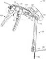
- FIG. 1is a perspective view of an embodiment of a system according to the present disclosure.
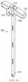
- FIG. 2is a cross-sectional view of one embodiment of a tensioner according to the present disclosure.
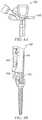
- FIG. 3Ais a perspective view of an embodiment of a counter tensioner according to the present disclosure and FIG. 3B is an exploded view of the counter tensioner of FIG. 3A .
- FIG. 4Ais a partial perspective view of an embodiment of a proximal end of the system in use in a first position and FIG. 4B is a partial perspective view of the distal end of the embodiment of FIG. 4A in use.
- FIG. 5Ais a partial perspective view of an embodiment of a proximal end of the system in use in a second position and FIG. 5B is a partial perspective view of the distal end of the embodiment of FIG. 5A in use.
- FIG. 6is a flow chart illustrating steps in one exemplary method according to the present disclosure.
- FIGS. 7A-7Gillustrate a cord tensioning system, according to various embodiments of the present disclosure.
- the present disclosureprovides for a system comprising a cord tensioner that can be rigidly, removably coupleable to a port disposed on a distal end of a counter tensioner, wherein the proximal end of the counter tensioner can be rigidly, removably coupleable to a head of an implant.
- a cord tensionerthat can be rigidly, removably coupleable to a port disposed on a distal end of a counter tensioner, wherein the proximal end of the counter tensioner can be rigidly, removably coupleable to a head of an implant.
- Such systems and methods of using the systemcan improve ergonomics and ease of use by, e.g., enabling one handed operation of a tensioner.
- Such systemscan also increase cord travel per actuation cycle of the cord tensioner and provide a visual indication of cord load during cord tensioning.
- the system 100can comprise a tensioner 102 and a counter tensioner 104 , which are used in combination for manipulating implants 106 coupleable by a cord 108 .
- the tensioner 102is designed to enable one-handed operation to apply tension to a cord 108 .
- the tensioner 102can comprise a nose assembly 110 for receiving the cord 108 and a cord lock assembly 112 for securing and applying tension to the cord 108 .
- the counter tensioner 104can be releasably coupleable to a head of an implant 106 at a distal end 114 thereof and can have a port 118 disposed in a proximal end 116 thereof.
- the port 118can be releasably coupleable the nose assembly 110 of the tensioner 102 .
- the counter tensioner 104can further be rigidly coupleable to both the head of the implant 106 and the nose assembly 110 , allowing a surgeon to tension the cord 108 via the tensioner 102 and translate the implant 106 and underlying vertebrae relative to another implant implanted in an adjacent or nearby vertebrae via a handle 130 in the same surgical step and as explained in greater detail below.
- the implant 106can be, for example and without limitation, a threaded fastener, a bone screw, a pedicle screw, a staple, a bone clamp, a universal bone clamp, cam blocks, bone plates, and the like. Furthermore, it is contemplated that the tensioner can be used to tension a cord between bones, clamps, or any implant secured to a bone in any manner.
- the implant 106can comprise a shaft that purchases underlying bone and a head including features for securely engaging an elongate member that, prior to being secured, can be tensioned to apply forces to manipulate the position of adjacent or nearby vertebrae as a juvenile patient experiences growth.
- the cordcan be, for example and without limitation, any elongate member including a cord, a tether, strap, a cable, a wire, a suture, a thread, or similar flexible ligature.
- the elongate membercan have some beneficial temporal elastic properties that could, for example and without limitation, avoid overcorrection or under correction over the life of an implanted system, and the like.
- the term “cord”is used throughout the present disclosure, but should be understood to include any elongate member.
- the tensioner 102can comprise a nose assembly 110 and a cord lock assembly 112 for applying tension to the cord 108 .
- the nose assembly 110 and the cord lock assembly 112can be at least partially disposed in the main body 124 of the tensioner 102
- the cord lock assembly 112can comprise a cord lock housing 208 disposed at a distal end of an elongate shaft 210 and can engage a cord 108 therein.
- the cord lock housing 208can comprise, for example and without limitation, a cam cleat 212 or the like for engaging and disengaging the cord 108 .
- the elongate shaft 210can be operably coupled to a shaft clutch 214 to drive the elongate shaft 210 distally and a shaft lock 216 that can resist return of the elongate shaft 210 in the proximal direction at the end point of an actuation cycle of the tensioner 102 .
- the shaft clutch 214can extend from a first end to a second end.
- the first endcan have an opening 215 disposed therein for receiving the elongate shaft 210 and the second end has a slot 217 disposed therein that is transverse to a longitudinal axis of the elongate shaft 210 .
- the slot 217receives a pin 219 extending from a front handle 218 .
- Actuation of the front handle 218shifts the opening 215 disposed in the first end of the shaft clutch 214 off angle to engage and distally translate the elongate shaft 210 as the front handle 218 is actuated towards a stationary rear handle 220 .
- the front handle 218can be rotatable about a pivot axis 126 (shown in FIG.
- a shaft spring 223 positioned distal to the shaft clutch 214 and about the elongate shaft 210can urge the shaft clutch 214 and front handle 218 back to the starting point of the actuation cycle of the tensioner 102 .
- the shaft lock 216can be biased via a distally-located lock spring 224 to allow distal translation but not proximal translation of the elongate shaft 210 .
- the shaft lock 216can be released by, articulating the shaft lock 216 distally if the tension on the cord 108 needs to be released, such as once the cord 108 is secured within the implant 106 .
- a cord nut 232 disposed proximate a distal end of the cord lock housing 208can be rotated to adjust the cord tension via engagement with threading 234 disposed on the distal end of the elongate shaft 210 .
- the elongate shaft 210can be distally translated from about 30 mm to about 35 mm during each actuation cycle or stroke of the shaft clutch 214 .
- the tensioner 102can be actuated via a single hand of a surgeon, freeing the other hand for performing other surgical tasks during and adjacent to cord tensioning.
- the nose assembly 110can comprise a piston 226 having a lumen 228 extending therethrough for receiving the cord and a load spring 230 positionable in contact with an indicator region 120 disposed on the piston 226 .
- the indicator region 120 of the piston 226can have a cross-sectional diameter than can be greater than or equal to any other portion of the piston 226 .
- a nose capcan retain the piston 226 and load spring 230 in the main body 124 of the tensioner 102 .
- the load spring 230can be calibrated so that the position of the indicator region 120 of the piston 226 correlates to the load applied to the cord as the cord 108 is tensioned and there is a counter pressure applied by the counter tensioner 104 to the nose assembly 110 .
- the indicator region 120can be visible through a window 122 disposed on the main body 124 of the tensioner 102 having indicia 128 printed adjacent thereto indicative of cord load at various indicator region positions relative to the tensioner main body 124 , as best illustrated in FIG. 1 .
- the piston 226can have a detent 236 disposed in a circumferential outer surface of the piston 226 proximate a proximal end thereof for coupling to the counter tensioner 104 .
- FIGS. 1, 3A, and 3BOne exemplary embodiment of a counter tensioner 104 according to the present disclosure is illustrated in FIGS. 1, 3A, and 3B .
- the counter tensioner 104can be releasably coupleable to the head of an implant 106 at a distal end 304 thereof.
- the counter tensioner 104can guide the cord 108 to a port 118 proximate the proximal end 308 thereof.
- the port 118can allow the cord to be fed through the nose assembly 110 to be secured in the cord lock housing 208 of the cord lock assembly 112 .
- the port 118can rigidly, releasably receive the nose assembly 110 of the tensioner 102 via a capture ball disposed in the port 118 for engaging the detent 236 of the piston 226 .
- the counter tensioner 104can further comprise a lumen 310 disposed therein extending from the distal end 304 to the proximal end 308 thereof.
- the port 118can be disposed at an angle that is not parallel to a longitudinal axis of the lumen 310 .
- a set screw(not shown) can be deliverable through the lumen 310 and engageable with the head of the implant to secure the cord therein with a driver (not shown).
- the counter tensioner 104can comprise a handle 130 that can facilitate translation of the implant 106 relative to another implant implanted in an adjacent or nearby vertebrae. Accordingly, vertebral translation, cord tensioning, and cord fixation can be performed in the same surgical step.
- the counter tensioner 104can further comprise an inner sleeve 314 and an outer sleeve 316 .
- the inner sleeve 314can comprise a plurality of outwardly biased arms at a distal end thereof that are engageable with cooperating features disposed on the head of the implant. Advancing the outer sleeve 316 distally over the inner sleeve 314 and at least partially over the head of the implant can urge the outwardly biased arms into secure engagement with cooperating features on the head of the implant.
- FIGS. 4A-5BAnother exemplary embodiment of a counter tensioner 400 according to the present disclosure is illustrated in FIGS. 4A-5B .
- the counter tensioner 400can comprise an inner sleeve 402 and an outer sleeve 404 .
- a distal end of the outer sleeve 404comprises a fulcrum 406 that can move from a first position where the fulcrum 406 is parallel to a longitudinal axis of the counter tensioner 400 to a second position where the fulcrum 406 pivots outwardly from the longitudinal axis of the counter tensioner 400 .
- the inner sleeve 402can comprise at least one projection 408 that can urge the fulcrum 406 outward as the outer sleeve 404 passes distally over the inner sleeve 402 and at least partially over the head of the implant.
- the fulcrum 406serves to change the cord angle, easing local tension on the cord as it is routed up to the tensioner 102 engaged in the port 118 .
- a pivoting latch 410can be provided at a proximal end of the inner sleeve 402 .
- the pivoting latch 410can be operatively coupled to the counter tensioner 400 so that the pivoting latch 410 moves downward as the fulcrum moves toward a parallel orientation relative to the longitudinal axis of the counter tensioner 400 and upward as the fulcrum pivots outwardly from the longitudinal axis of the counter tensioner.
- the fulcrumcan reduce stress applied to the cord during the tensioning process.
- FIG. 6is a flowchart illustrating a method 500 according to an exemplary embodiment.
- the method 500can include operations such as coupling a counter tensioner to an implant at 502 ; coupling a tensioner to the counter tensioner at 504 ; routing a cord through the counter tensioner and securing the cord in the tensioner at 506 ; and tensioning the cord at 508 .
- the method 500can begin at 502 with a counter tensioner, such as counter tensioner 104 , being inserted through an incision and coupled to a head of an implant.
- the counter tensioner 104includes an inner sleeve (e.g., inner sleeve 314 ) including biased arms located at a distal end thereof and an outer sleeve (e.g., outer sleeve 316 ).
- the biased armscan be engaged with cooperating features on the head of the implant, and the outer sleeve can subsequently be slid distally to lock the biased arms onto the head of the implant.
- the counter tensionercan include a threaded feature, a quick connect feature, or the like at a distal end thereof to couple the counter tensioner 104 to complementary features disposed on the head of the implant.
- the counter tensioner 104can engage the head of the implant such that the longitudinal axis of the implant and the longitudinal axis of the counter tensioner are not parallel and the cord can couple the counter tensioner to the implant.
- the method 500can continue with the tensioner 102 being coupled to the counter tensioner 104 .
- the tensioner 102includes a nose assembly 110 including a piston 226 formed from a cylinder with a detent 236 disposed in a circumferential outer surface and proximate a proximal end thereof.
- the detent 236 in the piston 226can engage a capture ball biased into the port 118 .
- the method 500can continue with guiding a cord from the proximal end of the counter tensioner 104 , through the port 118 and a lumen 228 disposed in a piston 226 of the nose assembly 110 of the tensioner 102 , and securing the cord within a cord lock housing 208 of a cord lock assembly 112 disposed at the end of an elongate shaft 210 , the cord being secured in an implant 106 in an adjacent or nearby vertebrae.
- the method 500can continue with tensioning the cord 108 by actuating a front handle 218 of the tensioner 102 to cause a shaft clutch 214 to engage and distally translate the elongate shaft 210 and the cord 108 .
- the method 500can continue by preventing proximal travel of the elongate shaft 210 at the end of the stroke of the shaft clutch 214 by causing the shaft lock 216 to engage and prevent return of the elongate shaft 210 .
- the method 500can include translating the implant and underlying vertebrae relative to an implant of an adjacent or nearby vertebrae.
- a surgeoncan grasp handle 130 to translate the implant coupled to the counter tensioner 104 .
- the steps of tensioning the cord and translating the vertebraecan be performed simultaneously.
- the methodcan further comprise indicating a load on the cord by the position of an indicator region of a piston of the nose assembly relative to indicia printed adjacent a window in a main body of the tensioner.
- the pistondepressed the load spring and an indicator region of the piston moves in the window disposed in the main body relative to the printed indicia printed adjacent to the window to indicate the load applied to the cord.
- FIGS. 7A-7GAnother exemplary embodiment of a cord tensioning system, system 700 , is illustrated in FIGS. 7A-7G .
- the system 700can comprise a tensioner 702 and a counter tensioner 704 , which are used in combination for manipulating implants 106 coupleable by a cord 108 (not illustrated in conjunction with this example).
- the tensioner 702is designed to enable one-handed operation to apply tension to a cord 108 (similar to that shown in FIG. 1 ).
- the tensioner 702includes similar structural features to tensioner 102 discussed in reference to FIGS. 1-3 , and will not be further described in reference to this example.
- the counter tensioner 704can be releasably coupleable to a head of an implant 106 at a distal end 714 thereof and can have a port 718 disposed in a proximal end 716 thereof.
- the port 718can releasably receive the nose assembly of the tensioner 702 (tensioner 102 is interchangeable with tensioner 702 ).
- the counter tensioner 704can further be rigidly coupleable to both the head of the implant 106 and the nose assembly, allowing a surgeon to tension the cord 108 via the tensioner 702 and translate the implant 106 and underlying vertebrae relative to another implant implanted in an adjacent or nearby vertebrae via a handle 730 in the same surgical step and as explained in greater detail below.
- the remaining discussion of counter tensioner 704focuses on the aspects that differ from examples discussed above.
- the counter tensioner 704includes a handle 730 with additional features, such as a lock position 732 , an unlock position 734 , and a lock handle 736 .
- the lock handle 736is rotatable between the lock position 732 and the unlock position 734 .
- the counter tensioner 704can be inserted over an implant, such as implant 106 (e.g., a pedicle screw). Once inserted over the pedicle screw, the lock handle 736 can be rotated into the lock position 732 and elements discussed below will lock the counter tensioner 704 to the pedicle screw. Internal workings of the lock mechanism are discussed in reference to FIGS. 7F and 7G below.
- FIGS. 7A-7Bonly illustrate locking extension 740 A and locking extension channel 742 A.
- the locking extensions 740 A, 740 Bare square elongate members connected at a proximal end to a locking mechanism operated by the lock handle 736 .
- the locking extensions 740 A, 740 Bcan be cylindrical rods or other cross-sectional profiles.
- the locking extension channels in this exampleare open square (or rectangular) channels, designed to fit the locking extensions 740 A, 740 B.
- FIGS. 7A and 7Balso illustrate a cord fulcrum 706 , a cord channel 708 , and a cord guide 710 A (cord guide 710 B is an opening on the opposing side of the distal end 714 not illustrated in this example).
- the cord guide 710 Aallows the cord to exit the counter tensioner 704 and pedicle screw.
- the cord guides 710 A, 710 Bare designed to complement the U-shaped pedicle screw head adapted to receive the cord.
- the cord fulcrum 706includes an enlarged radius area to smooth directional change in the cord from a first direction essentially transverse to a longitudinal axis of the counter tensioner 704 to a second direction essentially parallel the longitudinal axis (see FIG. 1 , the cord fulcrum 706 operates in a manner similar to fulcrum 106 ).
- the cord fulcrum 706is an integral part of the distal end 714 , and does not include any moving parts (e.g., does not pivot).
- the cord channel 708is a semi-circular recess in the elongate portion of the counter tensioner 704 .
- FIG. 7Cis a close-up perspective view of the distal end 714 of the counter tensioner 704 .
- a number of the structures discussed aboveare shown in additional detail, including the cord fulcrum 706 , the cord channel 708 , the cord guide 710 A, a distal end of the locking extension 740 A, the locking extension channel 742 A, and the pivot lock 750 A.
- FIG. 7Cillustrates the counter tensioner 704 in an unlocked position.
- the cord fulcrum 706in particular is shown in greater detail, in this figure it is easier to make out the radius created by the cord fulcrum 706 .
- the enlarged radiusprovides a smoother transition for the cord coming out of the cord guide 710 A and proceeding up along the cord channel 708 .
- FIGS. 7D and 7Eprovide cross sectional views of the distal end 714 of the counter tensioner 704 in an unlocked and locked state, respectively.
- the cross sectionsprovide a detailed view of both sides of the counter tensioner 704 .
- both locking extensions 740 A, 740 Bare shown extending down opposite sides of the counter tensioner 704 and terminating in extension wedges 744 A, 744 B.
- the extension wedges 744 A, 744 Btapper the locking extensions 740 A, 704 B down to a thin edge along the distal most portion.
- the extension wedges 744 A, 744 Btapper at approximately 60 degrees, but other tappers can be used.
- the extension wedges 744 A, 744 Bengage with lock wedges 756 A, 756 B, respectively.
- the lock wedges 756 A, 756 B in this exampletapper at a corresponding amount to produce an essentially opposing structure to the extension wedges 74 A 744 B.
- the ramp (tapper) angle on the lock wedges 756 A, 756 Bis slightly greater or slightly less than the extension wedges 756 A, 756 B to reduce friction between the surfaces.
- the locking mechanism within the handle 730operates to linearly translate the locking extensions 740 A, 740 B from the unlocked position shown in FIG. 7D to a locked position shown in FIG. 7E .
- the extension wedges 744 A, 744 Bengage the lock wedges 756 A, 756 B and cause the pivot locks 750 A, 750 B to rotate about pivots 754 A, 754 B to shift locking pins 752 A, 752 B into recesses within a head of the pedicle screw.
- the pivot locks 750 A, 750 Bare biased into an unlocked position by springs (not shown for clarity) disposed within spring recesses 758 A, 758 B with the springs held in place by spring pins 764 A, 764 B.
- the locking pins 752 A, 752 Boperate to secure the counter tensioner 704 on the pedicle screw head when pivoted into the locked position ( FIG. 7E ).
- the locking pins 752 A, 752 Bare cylindrical posts extending radially inward. In other examples, the locking pins 752 A, 752 B can be different cross-sectional shapes, such as square or rectangular.
- the pedicle screwis also surrounded by the pedicle screw receptacle 760 that includes pin openings 762 A, 762 B to receive the locking pins 752 A, 752 B, respectively.
- Pedicle screw receptacle 760receives the longitudinal bore 770 , which extends the length of the counter tensioner 704 .
- the longitudinal bore 770can allow for insertion of a closure top (e.g., set screw) into the pedicle screw to secure the cord.
- FIGS. 7D and 7Eillustrate cord guide 710 B with opposing cord guide 710 A shown in FIG. 7C .
- FIGS. 7F and 7Gprovide cross sectional views of the proximal end 716 of the counter tensioner 704 .
- the cross sectional viewsinclude details of the proximal lock mechanism 780 and interaction with the lock handle 736 .
- the proximal lock mechanism 780operates to linearly translate the locking extensions 740 A, 740 B, which in turn shift the pivot locks 750 A, 750 B from an unlocked to locked position as discussed above.
- the proximal lock mechanism 780includes a lock cylinder 782 coupled to the lock handle 736 through two lock cylinder set screws 738 A, 738 B.
- the lock handle 736rotates the lock cylinder 782 , which in turn causes translation of the locking extension 740 A, 740 B.
- the translationis accomplished, in this example, through interaction between a threaded cylinder 784 and a threaded internal portion of the lock cylinder 782 .
- the threaded cylinder 784is coupled to the locking extensions 740 A, 740 B through extension coupling pins 786 A, 786 B.
- the lock cylinder 782rotates with an internal threaded surface engaging the external threads on the threaded cylinder 784 , which is coupled to the locking extensions.
- the threaded interactioncauses the threaded cylinder 784 and locking extensions 740 A, 740 B to translate in a proximal-distal direction.
- Other mechanisms for translating the locking extensions 740 A, 740 Bcan be utilized without deviating from this basic design, such as a cam follower arrangement between the lock cylinder 782 and locking extensions 740 A, 740 B.
- FIG. 7Galso provides illustration of the cord conduit 720 leading to the tensioner port 718 .
- the cordcan be routed out of the cord guide 710 A, around the cord fulcrum 706 , proximally along the cord channel 708 , through the cord conduit 720 , and into the tensioner 702 through the tensioner port 718 .
- Example 1is a system for manipulating implants coupled by a cord and/or tensioning a cord extending between two or more implants.
- the systemcan include a tensioner and a counter tensioner.
- the tensionercan include a nose assembly and a cord lock assembly for applying tension to the cord, the nose assembly can comprise a piston having a lumen extending therethrough for receiving the cord and a spring positionable in contact with an indicator region of the piston.
- the counter tensioneroperates to guide the cord from the tensioner to an implant.
- the counter tensionercan include an elongate body with a proximal end and a distal end, where the proximal end includes a port to receive the nose assembly.
- the distal end of the counter tensioneris releasably coupleable to a head of the implant enabling translation of the implant relative to another implant implanted in an adjacent or nearby vertebrae.
- the tensioner indicator regioncan be visible through a window in a tensioner main body and indicates cord tension when the nose assembly of the tensioner is coupled to the port of the counter tensioner and engaged with the cord.
- example 2the subject matter of example 1 includes the counter tensioner having a lumen disposed within the elongate body and extending from the proximal end to the distal end thereof, and a set screw engageable with the head of the implant to fix the cord is deliverable through the lumen.
- the subject matter of any one of examples 1 or 2includes the port within the counter tensioner being disposed at an angle that is not parallel to a longitudinal axis of the lumen.
- any one of examples 1 to 3includes the nose assembly of the tensioner having a detent releasably coupleable in the port via a capture ball.
- the subject matter of any one of examples 1 to 4includes the counter tensioner including an inner sleeve and an outer sleeve, the inner sleeve comprising a plurality of outwardly biased arms at a distal end thereof that are engageable with cooperating features disposed on the head of the implant when the outer sleeve is translated distally over the inner sleeve and at least partially over the head of the implant to urge the plurality of outwardly biased arms into secure engagement with the cooperating features of the head of the implant.
- the subject matter of any one of examples 1 to 5includes the cord lock assembly of the tensioner including a cord lock housing for engaging the cord disposed at a distal end of an elongate shaft.
- example 7the subject matter of example 6 includes the cord lock housing having a cam cleat for engaging the cord.
- any one of examples 6 or 7includes the elongate shaft being operably coupled to a shaft clutch to drive the elongate shaft distally and a shaft lock to resist return of the elongate shaft in the proximal direction.
- example 9the subject matter of example 8 includes the shaft clutch being shifted off angle to engage and distally translate the elongate shaft by actuation of a front handle.
- the subject matter of example 9includes the front handle being rotatable about pivot axis that is transverse to a longitudinal axis extending from a proximal end to a distal end of the tensioner main body.
- the subject matter of any one of examples 9 or 10includes the shaft lock being biased via a distally-located spring to allow distal translation but not proximal translation of the elongate shaft.
- example 12the subject matter of example 8 includes the elongate shaft being distally translated from about 30 mm to about 35 mm during each complete stroke of the front handle.
- any one of examples 1 to 12includes the counter tensioner including a fulcrum disposed at the distal end thereof that articulates from an undeployed position to a deployed position to change the angle of the cord as it extends towards the tensioner from the distal end of the counter tensioner.
- any one of examples 1 to 13includes the tensioner being operable to tension the cord via a single hand of a user.
- any one of examples 1 to 14includes the indicator region of the piston having a greater cross-sectional diameter than any other portion of the piston.
- Example 16is a device for manipulating implants coupled by a cord and/or tensioning a cord extending between at least two implants.
- the deviceincludes a tensioning having a nose assembly and a cord lock assembly for applying tension to the cord, the nose assembly comprising a piston having a lumen extending therethrough for receiving the cord and a spring positionable in contact with an indicator region of the piston.
- the tensionercan be releasably coupleable to a port of a counter tensioner disposed at a distal end thereof and can be releasably coupleable to a head of an implant at a proximal end thereof.
- the indicator regionis visible through a window in a tensioner main body and indicates cord tension when the nose assembly of the tensioner is coupled to the port of the counter tensioner and engaged with the cord.
- example 17the subject matter of example 16 includes the nose assembly including a detent releasably coupleable in the port via a capture ball.
- any one of examples 16 or 17includes the cord lock assembly having a cord lock housing for engaging the cord disposed at a distal end of an elongate shaft.
- example 19the subject matter of example 18 includes the cord lock housing including a cam cleat for engaging the cord.
- any one of examples 18 or 19includes the elongate shaft being operably coupled to a shaft clutch to drive the elongate shaft distally and a shaft lock to resist return of the elongate shaft in the proximal direction.
- example 21the subject matter of example 20 optionally includes the shaft clutch is shifted off angle to engage and distally translate the elongate shaft by actuation of a front handle.
- example 22the subject matter of example 21 includes the front handle being rotatable about pivot axis that is transverse to a longitudinal axis extending from a proximal end to a distal end of the tensioner main body.
- any one of examples 21 or 22includes the shaft lock being biased via a distally-located spring to allow distal translation but not proximal translation of the elongate shaft.
- any one of examples 21 to 23includes the elongate shaft being distally translated from about 30 mm to about 35 mm during each complete stroke of the shaft clutch.
- any one of examples 16 to 24includes the tensioner is operable to tension the cord via a single hand of a user.
- any one of examples 16 to 25includes the indicator region of the piston having a greater cross-sectional diameter than any other portion of the piston.
- Example 27is a device for manipulating implants coupled by a cord or for assisting in tensioning a cord disposed between two implants.
- the deviceincludes a counter tensioner to guide the code from an implant to a tensioning device.
- the counter tensionerbeing releasably coupleable to a head of the implant at a proximal end thereof.
- the counter tensioneris operable to guide the cord to a port proximate the distal end thereof.
- the counter tensionercan enable translation of the implant relative to another implant implanted in an adjacent or nearby vertebrae.
- the counter tensionerincludes an elongate body including an inner sleeve and an outer sleeve.
- the inner sleevecomprises a plurality of outwardly biased arms at a distal end thereof that are engageable with cooperating features disposed on the head of the implant when the outer sleeve is translated distally over the inner sleeve and at least partially over the head of the implant to urge the plurality of outwardly biased arms into secure engagement with cooperating features of the head of the implant.
- the port of the counter tensioneris for receiving a nose assembly of a tensioner.
- example 28the subject matter of example 27 includes the counter tensioner having a lumen disposed within the elongate body extending from a proximal to a distal end thereof, and wherein a set screw engageable with the head of the implant to fix the cord is deliverable through the lumen.
- example 29the subject matter of example 28 includes the port being disposed at an angle that is not parallel to a longitudinal axis of the lumen.
- any one of examples 27 to 29includes the port including a capture ball releasably coupleable to a detent disposed in the nose assembly of the tensioner.
- any one of examples 27 to 30includes the counter tensioner comprising a fulcrum disposed at the distal end thereof to that is actuable from an undeployed position to a deployed position to change the angle of the cord as it extends towards the tensioner from the distal end of the counter tensioner.
- the terms “a” or “an”are used, as is common in patent documents, to include one or more than one, independent of any other instances or usages of “at least one” or “one or more.”
- the term “or”is used to refer to a nonexclusive or, such that “A or B” includes “A but not B,” “B but not A,” and “A and B,” unless otherwise indicated.
Landscapes
- Health & Medical Sciences (AREA)
- Orthopedic Medicine & Surgery (AREA)
- Neurology (AREA)
- Life Sciences & Earth Sciences (AREA)
- Surgery (AREA)
- Heart & Thoracic Surgery (AREA)
- Engineering & Computer Science (AREA)
- Biomedical Technology (AREA)
- Nuclear Medicine, Radiotherapy & Molecular Imaging (AREA)
- Medical Informatics (AREA)
- Molecular Biology (AREA)
- Animal Behavior & Ethology (AREA)
- General Health & Medical Sciences (AREA)
- Public Health (AREA)
- Veterinary Medicine (AREA)
- Surgical Instruments (AREA)
Abstract
Description
Claims (20)
Priority Applications (6)
| Application Number | Priority Date | Filing Date | Title |
|---|---|---|---|
| US16/115,441US10905474B2 (en) | 2017-08-29 | 2018-08-28 | Surgical cord tensioning devices, systems, and methods |
| US16/156,158US10939941B2 (en) | 2017-08-29 | 2018-10-10 | Surgical cord tensioning devices, systems, and methods |
| US17/141,657US12185991B2 (en) | 2017-08-29 | 2021-01-05 | Surgical cord tensioning devices, systems, and methods |
| US17/164,447US11690656B2 (en) | 2017-08-29 | 2021-02-01 | Surgical cord tensioning devices, systems, and methods |
| US18/330,595US20230310042A1 (en) | 2017-08-29 | 2023-06-07 | Surgical cord tensioning devices, systems, and methods |
| US19/010,587US20250134560A1 (en) | 2017-08-29 | 2025-01-06 | Surgical cord tensioning devices, systems, and methods |
Applications Claiming Priority (2)
| Application Number | Priority Date | Filing Date | Title |
|---|---|---|---|
| US201762551379P | 2017-08-29 | 2017-08-29 | |
| US16/115,441US10905474B2 (en) | 2017-08-29 | 2018-08-28 | Surgical cord tensioning devices, systems, and methods |
Related Child Applications (2)
| Application Number | Title | Priority Date | Filing Date |
|---|---|---|---|
| US16/156,158Continuation-In-PartUS10939941B2 (en) | 2017-08-29 | 2018-10-10 | Surgical cord tensioning devices, systems, and methods |
| US17/141,657ContinuationUS12185991B2 (en) | 2017-08-29 | 2021-01-05 | Surgical cord tensioning devices, systems, and methods |
Publications (2)
| Publication Number | Publication Date |
|---|---|
| US20190059958A1 US20190059958A1 (en) | 2019-02-28 |
| US10905474B2true US10905474B2 (en) | 2021-02-02 |
Family
ID=63528974
Family Applications (3)
| Application Number | Title | Priority Date | Filing Date |
|---|---|---|---|
| US16/115,441Active2038-12-29US10905474B2 (en) | 2017-08-29 | 2018-08-28 | Surgical cord tensioning devices, systems, and methods |
| US17/141,657Active2041-04-03US12185991B2 (en) | 2017-08-29 | 2021-01-05 | Surgical cord tensioning devices, systems, and methods |
| US19/010,587PendingUS20250134560A1 (en) | 2017-08-29 | 2025-01-06 | Surgical cord tensioning devices, systems, and methods |
Family Applications After (2)
| Application Number | Title | Priority Date | Filing Date |
|---|---|---|---|
| US17/141,657Active2041-04-03US12185991B2 (en) | 2017-08-29 | 2021-01-05 | Surgical cord tensioning devices, systems, and methods |
| US19/010,587PendingUS20250134560A1 (en) | 2017-08-29 | 2025-01-06 | Surgical cord tensioning devices, systems, and methods |
Country Status (6)
| Country | Link |
|---|---|
| US (3) | US10905474B2 (en) |
| EP (1) | EP3675755B1 (en) |
| AU (1) | AU2018323471B2 (en) |
| CA (2) | CA3073564C (en) |
| ES (1) | ES2900054T3 (en) |
| WO (1) | WO2019046339A1 (en) |
Cited By (3)
| Publication number | Priority date | Publication date | Assignee | Title |
|---|---|---|---|---|
| WO2022154966A1 (en) | 2021-01-18 | 2022-07-21 | Zimmer Biomet Spine, Inc. | Spinal tethering devices, systems, and methods |
| US11690656B2 (en) | 2017-08-29 | 2023-07-04 | Zimmer Biomet Spine, Inc. | Surgical cord tensioning devices, systems, and methods |
| US12185991B2 (en) | 2017-08-29 | 2025-01-07 | Zimmer Biomet Spine, Inc. | Surgical cord tensioning devices, systems, and methods |
Families Citing this family (5)
| Publication number | Priority date | Publication date | Assignee | Title |
|---|---|---|---|---|
| US11020149B2 (en)* | 2018-02-28 | 2021-06-01 | Globus Medical Inc. | Scoliosis correction systems, methods, and instruments |
| US11819255B2 (en)* | 2019-10-07 | 2023-11-21 | Ortho Development Corporation | Tether tensioning instrumentation and related methods |
| AU2020264377A1 (en)* | 2019-11-08 | 2021-05-27 | K2M, Inc. | Anterior tether tensioner |
| WO2022050304A1 (en)* | 2020-09-02 | 2022-03-10 | 京セラ株式会社 | Grip holder for medical instrument, and instrument for spinal operation |
| US20220110661A1 (en)* | 2020-10-12 | 2022-04-14 | Globus Medical, Inc. | Scoliosis correction systems, methods, and instruments |
Citations (58)
| Publication number | Priority date | Publication date | Assignee | Title |
|---|---|---|---|---|
| US5423848A (en) | 1992-04-14 | 1995-06-13 | Olympus Optical Co., Ltd. | Trocar |
| US6251111B1 (en) | 1999-10-20 | 2001-06-26 | Sdgi Holdings, Inc. | Jack for pulling a vertebral anchor |
| US6296643B1 (en) | 1999-04-23 | 2001-10-02 | Sdgi Holdings, Inc. | Device for the correction of spinal deformities through vertebral body tethering without fusion |
| US20020032450A1 (en) | 1999-11-19 | 2002-03-14 | Pioneer Laboratories, Inc. | Method and apparatus for clamping surgical wires or cables |
| US20050010220A1 (en) | 2003-04-24 | 2005-01-13 | Simon Casutt | Instrument system for pedicle screws |
| US7083621B2 (en) | 2003-04-25 | 2006-08-01 | Sdgi Holdings, Inc. | Articulating spinal fixation rod and system |
| US20070021737A1 (en) | 2005-04-14 | 2007-01-25 | Woojin Lee | Surgical instrument guide device |
| US20070093846A1 (en) | 2005-10-12 | 2007-04-26 | Robert Frigg | Apparatus and methods for vertebral augmentation |
| US20070213714A1 (en) | 2006-02-07 | 2007-09-13 | Sdgi Holdings, Inc. | Surgical instruments and techniques for percutaneous placement of spinal stabilization elements |
| US20080009863A1 (en) | 2006-06-23 | 2008-01-10 | Zimmer Spine, Inc. | Pedicle screw distractor and associated method of use |
| US20080077138A1 (en) | 2006-09-26 | 2008-03-27 | Cohen Dan S | Percutaneous instrument assembly |
| US20080132933A1 (en) | 2006-11-30 | 2008-06-05 | Medtronic, Inc. | Flexible introducer |
| US20080243052A1 (en) | 2007-03-26 | 2008-10-02 | Warsaw Orthopedic, Inc. | Guide and Method for Inserting an Elongated Member Into a Patient |
| US20080287951A1 (en) | 2007-03-22 | 2008-11-20 | Stoneburner James D | Segmented intramedullary structure |
| US20090054933A1 (en) | 2007-08-21 | 2009-02-26 | Depuy Spine, Inc. | Instruments and methods for tensioning a spinal tether |
| US20090082776A1 (en) | 2007-09-26 | 2009-03-26 | Ebi, L.P. | External fixation tensioner |
| US20090088799A1 (en) | 2007-10-01 | 2009-04-02 | Chung-Chun Yeh | Spinal fixation device having a flexible cable and jointed components received thereon |
| EP2047813A1 (en) | 2007-10-11 | 2009-04-15 | Abbott Spine | Bone fixing system and method of use |
| US20090163962A1 (en) | 2007-12-20 | 2009-06-25 | Aesculap Implant Systems, Inc. | Locking device introducer instrument |
| US7556630B2 (en) | 2003-01-10 | 2009-07-07 | Warsaw Orthopedic, Inc. | Flexible member tensioning instruments and methods |
| US20090198281A1 (en) | 2008-02-05 | 2009-08-06 | Zimmer Spine, Inc. | System and method for insertion of flexible spinal stabilization element |
| US20100042106A1 (en) | 2008-08-12 | 2010-02-18 | Bryant Mark A | Surgical cable tensioning apparatus and method |
| US20100168803A1 (en) | 2008-12-29 | 2010-07-01 | Zimmer Spine, Inc. | Flexible Guide for Insertion of a Vertebral Stabilization System |
| US20100318137A1 (en) | 2009-06-11 | 2010-12-16 | Simon Stucki | Internal Cable Fixator |
| US20110060367A1 (en) | 2009-09-09 | 2011-03-10 | Marshall Ephraim Stauber | Spine Surgery Device And Method |
| US7909857B2 (en) | 2008-03-26 | 2011-03-22 | Warsaw Orthopedic, Inc. | Devices and methods for correcting spinal deformities |
| US7909826B2 (en) | 2005-03-24 | 2011-03-22 | Depuy Spine, Inc. | Low profile spinal tethering methods |
| US20110184473A1 (en) | 2010-01-22 | 2011-07-28 | Javier Garcia-Bengochea | Method and apparatus for spinal fixation using minimally invasive surgical techniques |
| US8118841B2 (en) | 2004-03-23 | 2012-02-21 | Warsaw Orthopedic, Inc. | Device for dynamic spinal fixation for correction of spinal deformities |
| US20120221054A1 (en) | 2007-05-01 | 2012-08-30 | Jackson Roger P | Soft stabilization assemblies with pretensioned cords |
| US20120259374A1 (en) | 2011-04-11 | 2012-10-11 | Warsaw Orthopedic, Inc. | Flexible Anchor Extenders |
| US8308771B2 (en) | 2008-06-06 | 2012-11-13 | Simpirica Spine, Inc. | Methods and apparatus for locking a band |
| US8337528B2 (en) | 2006-11-28 | 2012-12-25 | Anova Corporation | Methods and apparatus for stabilizing a spinal segment |
| US8454662B2 (en) | 2006-12-08 | 2013-06-04 | Warsaw Orthopedic, Inc. | Tethers with strength limits for treating vertebral members |
| US8465526B2 (en) | 2007-04-30 | 2013-06-18 | Globus Medical, Inc. | Flexible spine stabilization system |
| US8562653B2 (en) | 2009-03-10 | 2013-10-22 | Simpirica Spine, Inc. | Surgical tether apparatus and methods of use |
| US8591560B2 (en) | 2005-09-30 | 2013-11-26 | Roger P. Jackson | Dynamic stabilization connecting member with elastic core and outer sleeve |
| US8632572B2 (en) | 2007-04-19 | 2014-01-21 | Zimmer Spine, Inc. | Method and associated instrumentation for installation of spinal dynamic stabilization system |
| US8641736B2 (en) | 2012-01-20 | 2014-02-04 | Warsaw Orthopedic, Inc. | Vertebral fastener system |
| US8764803B2 (en) | 2012-10-04 | 2014-07-01 | Loubert S. Suddaby | Apparatus and method for aligning a spine |
| US20140243907A1 (en) | 2013-02-27 | 2014-08-28 | Biomet C.V. | Periprosthetic Fracture Repair System Including Discrete Stabilized Crimp Lugs for Cerclage Cable and Tool Therefor |
| US20140276051A1 (en) | 2013-03-13 | 2014-09-18 | Gyrus ACM, Inc. (d.b.a Olympus Surgical Technologies America) | Device for Minimally Invasive Delivery of Treatment Substance |
| US20150066042A1 (en) | 2012-01-25 | 2015-03-05 | Spinal Usa, Inc. | Minimally invasive devices and methods for delivering fixation devices and implants into a spine |
| US8992578B2 (en) | 2004-05-28 | 2015-03-31 | Depuy Synthes Products Llc | Anchoring systems and methods for correcting spinal deformities |
| US20150127003A1 (en) | 2013-03-15 | 2015-05-07 | Frontier Medical Devices, Inc. | Cable fixation device |
| US20150209077A1 (en) | 2014-01-24 | 2015-07-30 | Medtronic, Inc. | Implant tools for extravascular implantation of medical leads |
| US9101408B1 (en) | 2014-08-20 | 2015-08-11 | ZynFusion, LLC | Minimally invasive spinal fusion system and method |
| US20150342654A1 (en) | 2014-05-28 | 2015-12-03 | Pioneer Surgical Technology, Inc. | Tensioning instruments |
| US20160000468A1 (en) | 2013-03-15 | 2016-01-07 | Shriners Hospitals For Children | Methods and techniques for spinal surgery |
| US20160074147A1 (en) | 2014-09-12 | 2016-03-17 | Boston Scientific Scimed, Inc. | Reusable delivery devices |
| US9526525B2 (en) | 2006-08-22 | 2016-12-27 | Neuropro Technologies, Inc. | Percutaneous system for dynamic spinal stabilization |
| US9833275B2 (en) | 2007-08-21 | 2017-12-05 | DePuy Synthes Products, Inc. | Tether tensioning instrument |
| US20180029824A1 (en) | 2016-07-29 | 2018-02-01 | Pioneer Surgical Technology, Inc. | Surgical Cable Tensioner |
| US20190059959A1 (en) | 2017-08-29 | 2019-02-28 | Zimmer Biomet Spine, Inc. | Surgical cord tensioning devices, systems, and methods |
| WO2019046339A1 (en) | 2017-08-29 | 2019-03-07 | Zimmer Biomet Spine, Inc. | Surgical cord tensioning devices, systems, and methods |
| US20190262039A1 (en) | 2018-02-28 | 2019-08-29 | Globus Medical, Inc. | Scoliosis correction systems, methods, and instruments |
| US20190336182A1 (en) | 2015-10-27 | 2019-11-07 | Ctl Medical Corporation | Modular rod reduction tower and related methods |
| WO2020077029A1 (en) | 2018-10-10 | 2020-04-16 | Zimmer Biomet Spine, Inc. | Surgical cord tensioning devices and systems |
Family Cites Families (2)
| Publication number | Priority date | Publication date | Assignee | Title |
|---|---|---|---|---|
| FR2777449B1 (en)* | 1998-04-17 | 2000-09-15 | Sulzer Orthopedics Limited | TENSIONING DEVICE FOR LAYING A SPINAL STABILIZATION SYSTEM |
| US10022159B2 (en)* | 2015-12-18 | 2018-07-17 | Warsaw Orthopedic, Inc. | Surgical instrument and method |
- 2018
- 2018-08-28CACA3073564Apatent/CA3073564C/enactiveActive
- 2018-08-28EPEP18766509.6Apatent/EP3675755B1/enactiveActive
- 2018-08-28ESES18766509Tpatent/ES2900054T3/enactiveActive
- 2018-08-28CACA3153819Apatent/CA3153819A1/enactivePending
- 2018-08-28WOPCT/US2018/048403patent/WO2019046339A1/ennot_activeCeased
- 2018-08-28AUAU2018323471Apatent/AU2018323471B2/enactiveActive
- 2018-08-28USUS16/115,441patent/US10905474B2/enactiveActive
- 2021
- 2021-01-05USUS17/141,657patent/US12185991B2/enactiveActive
- 2025
- 2025-01-06USUS19/010,587patent/US20250134560A1/enactivePending
Patent Citations (72)
| Publication number | Priority date | Publication date | Assignee | Title |
|---|---|---|---|---|
| US5423848A (en) | 1992-04-14 | 1995-06-13 | Olympus Optical Co., Ltd. | Trocar |
| US6296643B1 (en) | 1999-04-23 | 2001-10-02 | Sdgi Holdings, Inc. | Device for the correction of spinal deformities through vertebral body tethering without fusion |
| US6251111B1 (en) | 1999-10-20 | 2001-06-26 | Sdgi Holdings, Inc. | Jack for pulling a vertebral anchor |
| US20020032450A1 (en) | 1999-11-19 | 2002-03-14 | Pioneer Laboratories, Inc. | Method and apparatus for clamping surgical wires or cables |
| US7556630B2 (en) | 2003-01-10 | 2009-07-07 | Warsaw Orthopedic, Inc. | Flexible member tensioning instruments and methods |
| US20050010220A1 (en) | 2003-04-24 | 2005-01-13 | Simon Casutt | Instrument system for pedicle screws |
| US7073415B2 (en) | 2003-04-24 | 2006-07-11 | Centerpulse Orthopedics Ltd. | Instrument system for pedicle screws |
| US7083621B2 (en) | 2003-04-25 | 2006-08-01 | Sdgi Holdings, Inc. | Articulating spinal fixation rod and system |
| US8118841B2 (en) | 2004-03-23 | 2012-02-21 | Warsaw Orthopedic, Inc. | Device for dynamic spinal fixation for correction of spinal deformities |
| US8992578B2 (en) | 2004-05-28 | 2015-03-31 | Depuy Synthes Products Llc | Anchoring systems and methods for correcting spinal deformities |
| US8123749B2 (en) | 2005-03-24 | 2012-02-28 | Depuy Spine, Inc. | Low profile spinal tethering systems |
| US8888818B2 (en) | 2005-03-24 | 2014-11-18 | DePuy Synthes Products, LLC | Low profile spinal tethering methods |
| US8273086B2 (en) | 2005-03-24 | 2012-09-25 | Depuy Spine, Inc. | Low profile spinal tethering devices |
| US7909826B2 (en) | 2005-03-24 | 2011-03-22 | Depuy Spine, Inc. | Low profile spinal tethering methods |
| US9492165B2 (en) | 2005-03-24 | 2016-11-15 | DePuy Synthes Products, Inc. | Low profile spinal tethering devices |
| US20170027616A1 (en) | 2005-03-24 | 2017-02-02 | DePuy Synthes Products, Inc. | Low profile spinal tethering devices |
| US20070021737A1 (en) | 2005-04-14 | 2007-01-25 | Woojin Lee | Surgical instrument guide device |
| US8591560B2 (en) | 2005-09-30 | 2013-11-26 | Roger P. Jackson | Dynamic stabilization connecting member with elastic core and outer sleeve |
| US20070093846A1 (en) | 2005-10-12 | 2007-04-26 | Robert Frigg | Apparatus and methods for vertebral augmentation |
| US20070213714A1 (en) | 2006-02-07 | 2007-09-13 | Sdgi Holdings, Inc. | Surgical instruments and techniques for percutaneous placement of spinal stabilization elements |
| US20080009863A1 (en) | 2006-06-23 | 2008-01-10 | Zimmer Spine, Inc. | Pedicle screw distractor and associated method of use |
| US9526525B2 (en) | 2006-08-22 | 2016-12-27 | Neuropro Technologies, Inc. | Percutaneous system for dynamic spinal stabilization |
| US20080077138A1 (en) | 2006-09-26 | 2008-03-27 | Cohen Dan S | Percutaneous instrument assembly |
| US8337528B2 (en) | 2006-11-28 | 2012-12-25 | Anova Corporation | Methods and apparatus for stabilizing a spinal segment |
| US20080132933A1 (en) | 2006-11-30 | 2008-06-05 | Medtronic, Inc. | Flexible introducer |
| US8454662B2 (en) | 2006-12-08 | 2013-06-04 | Warsaw Orthopedic, Inc. | Tethers with strength limits for treating vertebral members |
| US20080287951A1 (en) | 2007-03-22 | 2008-11-20 | Stoneburner James D | Segmented intramedullary structure |
| US20080243052A1 (en) | 2007-03-26 | 2008-10-02 | Warsaw Orthopedic, Inc. | Guide and Method for Inserting an Elongated Member Into a Patient |
| US8632572B2 (en) | 2007-04-19 | 2014-01-21 | Zimmer Spine, Inc. | Method and associated instrumentation for installation of spinal dynamic stabilization system |
| US9339297B2 (en) | 2007-04-30 | 2016-05-17 | Globus Medical, Inc. | Flexible spine stabilization system |
| US8465526B2 (en) | 2007-04-30 | 2013-06-18 | Globus Medical, Inc. | Flexible spine stabilization system |
| US9211142B2 (en) | 2007-04-30 | 2015-12-15 | Globus Medical, Inc. | Flexible element for spine stabilization system |
| US20120221054A1 (en) | 2007-05-01 | 2012-08-30 | Jackson Roger P | Soft stabilization assemblies with pretensioned cords |
| US9039711B2 (en) | 2007-08-21 | 2015-05-26 | DePuy Synthes Products, Inc. | Instruments and methods for tensioning a spinal tether |
| US9833275B2 (en) | 2007-08-21 | 2017-12-05 | DePuy Synthes Products, Inc. | Tether tensioning instrument |
| US20090054933A1 (en) | 2007-08-21 | 2009-02-26 | Depuy Spine, Inc. | Instruments and methods for tensioning a spinal tether |
| US9370390B2 (en) | 2007-08-21 | 2016-06-21 | DePuy Synthes Products, Inc. | Instruments and methods for tensioning a spinal tether |
| US20160262811A1 (en) | 2007-08-21 | 2016-09-15 | DePuy Synthes Products, Inc. | Instruments and methods for tensioning a spinal tether |
| US20090082776A1 (en) | 2007-09-26 | 2009-03-26 | Ebi, L.P. | External fixation tensioner |
| US20090088799A1 (en) | 2007-10-01 | 2009-04-02 | Chung-Chun Yeh | Spinal fixation device having a flexible cable and jointed components received thereon |
| EP2047813A1 (en) | 2007-10-11 | 2009-04-15 | Abbott Spine | Bone fixing system and method of use |
| US20090163962A1 (en) | 2007-12-20 | 2009-06-25 | Aesculap Implant Systems, Inc. | Locking device introducer instrument |
| US20150313644A1 (en) | 2008-02-05 | 2015-11-05 | Zimmer Spine, Inc. | System and method for insertion of flexible spinal stabilization element |
| US20090198281A1 (en) | 2008-02-05 | 2009-08-06 | Zimmer Spine, Inc. | System and method for insertion of flexible spinal stabilization element |
| US9277940B2 (en) | 2008-02-05 | 2016-03-08 | Zimmer Spine, Inc. | System and method for insertion of flexible spinal stabilization element |
| US7909857B2 (en) | 2008-03-26 | 2011-03-22 | Warsaw Orthopedic, Inc. | Devices and methods for correcting spinal deformities |
| US9011498B2 (en) | 2008-03-26 | 2015-04-21 | Warsaw Orthopedic, Inc. | Devices and methods for correcting spinal deformities |
| US8308771B2 (en) | 2008-06-06 | 2012-11-13 | Simpirica Spine, Inc. | Methods and apparatus for locking a band |
| US20100042106A1 (en) | 2008-08-12 | 2010-02-18 | Bryant Mark A | Surgical cable tensioning apparatus and method |
| US20100168803A1 (en) | 2008-12-29 | 2010-07-01 | Zimmer Spine, Inc. | Flexible Guide for Insertion of a Vertebral Stabilization System |
| US8562653B2 (en) | 2009-03-10 | 2013-10-22 | Simpirica Spine, Inc. | Surgical tether apparatus and methods of use |
| US20100318137A1 (en) | 2009-06-11 | 2010-12-16 | Simon Stucki | Internal Cable Fixator |
| US20110060367A1 (en) | 2009-09-09 | 2011-03-10 | Marshall Ephraim Stauber | Spine Surgery Device And Method |
| US20110184473A1 (en) | 2010-01-22 | 2011-07-28 | Javier Garcia-Bengochea | Method and apparatus for spinal fixation using minimally invasive surgical techniques |
| US20120259374A1 (en) | 2011-04-11 | 2012-10-11 | Warsaw Orthopedic, Inc. | Flexible Anchor Extenders |
| US8641736B2 (en) | 2012-01-20 | 2014-02-04 | Warsaw Orthopedic, Inc. | Vertebral fastener system |
| US20150066042A1 (en) | 2012-01-25 | 2015-03-05 | Spinal Usa, Inc. | Minimally invasive devices and methods for delivering fixation devices and implants into a spine |
| US8764803B2 (en) | 2012-10-04 | 2014-07-01 | Loubert S. Suddaby | Apparatus and method for aligning a spine |
| US20140243907A1 (en) | 2013-02-27 | 2014-08-28 | Biomet C.V. | Periprosthetic Fracture Repair System Including Discrete Stabilized Crimp Lugs for Cerclage Cable and Tool Therefor |
| US20140276051A1 (en) | 2013-03-13 | 2014-09-18 | Gyrus ACM, Inc. (d.b.a Olympus Surgical Technologies America) | Device for Minimally Invasive Delivery of Treatment Substance |
| US20160000468A1 (en) | 2013-03-15 | 2016-01-07 | Shriners Hospitals For Children | Methods and techniques for spinal surgery |
| US20150127003A1 (en) | 2013-03-15 | 2015-05-07 | Frontier Medical Devices, Inc. | Cable fixation device |
| US20150209077A1 (en) | 2014-01-24 | 2015-07-30 | Medtronic, Inc. | Implant tools for extravascular implantation of medical leads |
| US20150342654A1 (en) | 2014-05-28 | 2015-12-03 | Pioneer Surgical Technology, Inc. | Tensioning instruments |
| US9101408B1 (en) | 2014-08-20 | 2015-08-11 | ZynFusion, LLC | Minimally invasive spinal fusion system and method |
| US20160074147A1 (en) | 2014-09-12 | 2016-03-17 | Boston Scientific Scimed, Inc. | Reusable delivery devices |
| US20190336182A1 (en) | 2015-10-27 | 2019-11-07 | Ctl Medical Corporation | Modular rod reduction tower and related methods |
| US20180029824A1 (en) | 2016-07-29 | 2018-02-01 | Pioneer Surgical Technology, Inc. | Surgical Cable Tensioner |
| US20190059959A1 (en) | 2017-08-29 | 2019-02-28 | Zimmer Biomet Spine, Inc. | Surgical cord tensioning devices, systems, and methods |
| WO2019046339A1 (en) | 2017-08-29 | 2019-03-07 | Zimmer Biomet Spine, Inc. | Surgical cord tensioning devices, systems, and methods |
| US20190262039A1 (en) | 2018-02-28 | 2019-08-29 | Globus Medical, Inc. | Scoliosis correction systems, methods, and instruments |
| WO2020077029A1 (en) | 2018-10-10 | 2020-04-16 | Zimmer Biomet Spine, Inc. | Surgical cord tensioning devices and systems |
Non-Patent Citations (10)
Cited By (4)
| Publication number | Priority date | Publication date | Assignee | Title |
|---|---|---|---|---|
| US11690656B2 (en) | 2017-08-29 | 2023-07-04 | Zimmer Biomet Spine, Inc. | Surgical cord tensioning devices, systems, and methods |
| US12185991B2 (en) | 2017-08-29 | 2025-01-07 | Zimmer Biomet Spine, Inc. | Surgical cord tensioning devices, systems, and methods |
| WO2022154966A1 (en) | 2021-01-18 | 2022-07-21 | Zimmer Biomet Spine, Inc. | Spinal tethering devices, systems, and methods |
| US12048460B2 (en) | 2021-01-18 | 2024-07-30 | Zimmer Biomet Spine, Inc. | Spinal tethering devices, systems, and methods |
Also Published As
| Publication number | Publication date |
|---|---|
| AU2018323471B2 (en) | 2020-10-08 |
| CA3073564A1 (en) | 2019-03-07 |
| AU2018323471A1 (en) | 2020-03-19 |
| WO2019046339A1 (en) | 2019-03-07 |
| US20210121208A1 (en) | 2021-04-29 |
| ES2900054T3 (en) | 2022-03-15 |
| EP3675755B1 (en) | 2021-11-24 |
| US20190059958A1 (en) | 2019-02-28 |
| US20250134560A1 (en) | 2025-05-01 |
| CA3073564C (en) | 2022-10-18 |
| CA3153819A1 (en) | 2019-03-07 |
| US12185991B2 (en) | 2025-01-07 |
| EP3675755A1 (en) | 2020-07-08 |
Similar Documents
| Publication | Publication Date | Title |
|---|---|---|
| US20210121208A1 (en) | Surgical cord tensioning devices, systems, and methods | |
| US20230310042A1 (en) | Surgical cord tensioning devices, systems, and methods | |
| US11039863B2 (en) | Apparatus and methods for reduction of vertebral bodies in a spine | |
| US7758584B2 (en) | Minimally invasive fixation system | |
| JP5547851B2 (en) | System for percutaneously securing a connecting rod to the spinal column | |
| US8979850B2 (en) | Surgical guide device | |
| US8512383B2 (en) | Method of percutaneously fixing a connecting rod to a spine | |
| EP3684276B1 (en) | Band tensioning system | |
| US20080234678A1 (en) | Rod reducer | |
| WO2013187928A1 (en) | Pedicle screw extension for use in percutaneous spinal fixation | |
| AU2019358075B2 (en) | Surgical cord tensioning devices and systems | |
| US20250099143A1 (en) | Rotating rod reducer |
Legal Events
| Date | Code | Title | Description |
|---|---|---|---|
| FEPP | Fee payment procedure | Free format text:ENTITY STATUS SET TO UNDISCOUNTED (ORIGINAL EVENT CODE: BIG.); ENTITY STATUS OF PATENT OWNER: LARGE ENTITY | |
| AS | Assignment | Owner name:ZIMMER BIOMET SPINE, INC., COLORADO Free format text:ASSIGNMENT OF ASSIGNORS INTEREST;ASSIGNOR:MAST, RANDALL G;REEL/FRAME:046749/0123 Effective date:20180829 | |
| STPP | Information on status: patent application and granting procedure in general | Free format text:DOCKETED NEW CASE - READY FOR EXAMINATION | |
| STPP | Information on status: patent application and granting procedure in general | Free format text:NON FINAL ACTION MAILED | |
| STPP | Information on status: patent application and granting procedure in general | Free format text:NON FINAL ACTION MAILED | |
| STCF | Information on status: patent grant | Free format text:PATENTED CASE | |
| AS | Assignment | Owner name:JPMORGAN CHASE BANK, N.A., AS ADMINISTRATIVE AGENT, NEW YORK Free format text:SECURITY INTEREST;ASSIGNORS:BIOMET 3I, LLC;EBI, LLC;ZIMMER BIOMET SPINE, INC.;AND OTHERS;REEL/FRAME:059293/0213 Effective date:20220228 | |
| AS | Assignment | Owner name:CERBERUS BUSINESS FINANCE AGENCY, LLC, NEW YORK Free format text:GRANT OF A SECURITY INTEREST -- PATENTS;ASSIGNORS:ZIMMER BIOMET SPINE, LLC;EBI, LLC;REEL/FRAME:066970/0806 Effective date:20240401 | |
| AS | Assignment | Owner name:ZIMMER BIOMET SPINE, LLC (F/K/A ZIMMER BIOMET SPINE, INC.), COLORADO Free format text:RELEASE BY SECURED PARTY;ASSIGNOR:JPMORGAN CHASE BANK, N.A.;REEL/FRAME:066973/0833 Effective date:20240401 Owner name:EBI, LLC, NEW JERSEY Free format text:RELEASE BY SECURED PARTY;ASSIGNOR:JPMORGAN CHASE BANK, N.A.;REEL/FRAME:066973/0833 Effective date:20240401 | |
| MAFP | Maintenance fee payment | Free format text:PAYMENT OF MAINTENANCE FEE, 4TH YEAR, LARGE ENTITY (ORIGINAL EVENT CODE: M1551); ENTITY STATUS OF PATENT OWNER: LARGE ENTITY Year of fee payment:4 | |
| AS | Assignment | Owner name:ZIMMER BIOMET SPINE, LLC, COLORADO Free format text:CHANGE OF NAME;ASSIGNOR:ZIMMER BIOMET SPINE, INC.;REEL/FRAME:069772/0121 Effective date:20240220 Owner name:HIGHRIDGE MEDICAL, LLC, COLORADO Free format text:CHANGE OF NAME;ASSIGNOR:ZIMMER BIOMET SPINE, LLC;REEL/FRAME:069772/0248 Effective date:20240405 |