US10905415B2 - Surgical stapler with electromechanical lockout - Google Patents
Surgical stapler with electromechanical lockoutDownload PDFInfo
- Publication number
- US10905415B2 US10905415B2US14/751,215US201514751215AUS10905415B2US 10905415 B2US10905415 B2US 10905415B2US 201514751215 AUS201514751215 AUS 201514751215AUS 10905415 B2US10905415 B2US 10905415B2
- Authority
- US
- United States
- Prior art keywords
- assembly
- trigger
- lockout
- anvil
- drive
- Prior art date
- Legal status (The legal status is an assumption and is not a legal conclusion. Google has not performed a legal analysis and makes no representation as to the accuracy of the status listed.)
- Active, expires
Links
Images


Classifications
- A—HUMAN NECESSITIES
- A61—MEDICAL OR VETERINARY SCIENCE; HYGIENE
- A61B—DIAGNOSIS; SURGERY; IDENTIFICATION
- A61B17/00—Surgical instruments, devices or methods
- A61B17/11—Surgical instruments, devices or methods for performing anastomosis; Buttons for anastomosis
- A61B17/115—Staplers for performing anastomosis, e.g. in a single operation
- A61B17/1155—Circular staplers comprising a plurality of staples
- A—HUMAN NECESSITIES
- A61—MEDICAL OR VETERINARY SCIENCE; HYGIENE
- A61B—DIAGNOSIS; SURGERY; IDENTIFICATION
- A61B17/00—Surgical instruments, devices or methods
- A61B17/068—Surgical staplers, e.g. containing multiple staples or clamps
- A—HUMAN NECESSITIES
- A61—MEDICAL OR VETERINARY SCIENCE; HYGIENE
- A61B—DIAGNOSIS; SURGERY; IDENTIFICATION
- A61B17/00—Surgical instruments, devices or methods
- A61B17/068—Surgical staplers, e.g. containing multiple staples or clamps
- A61B17/072—Surgical staplers, e.g. containing multiple staples or clamps for applying a row of staples in a single action, e.g. the staples being applied simultaneously
- A61B17/07207—Surgical staplers, e.g. containing multiple staples or clamps for applying a row of staples in a single action, e.g. the staples being applied simultaneously the staples being applied sequentially
- A—HUMAN NECESSITIES
- A61—MEDICAL OR VETERINARY SCIENCE; HYGIENE
- A61B—DIAGNOSIS; SURGERY; IDENTIFICATION
- A61B17/00—Surgical instruments, devices or methods
- A61B17/11—Surgical instruments, devices or methods for performing anastomosis; Buttons for anastomosis
- A61B17/1114—Surgical instruments, devices or methods for performing anastomosis; Buttons for anastomosis of the digestive tract, e.g. bowels or oesophagus
- A—HUMAN NECESSITIES
- A61—MEDICAL OR VETERINARY SCIENCE; HYGIENE
- A61B—DIAGNOSIS; SURGERY; IDENTIFICATION
- A61B17/00—Surgical instruments, devices or methods
- A61B2017/00017—Electrical control of surgical instruments
- A—HUMAN NECESSITIES
- A61—MEDICAL OR VETERINARY SCIENCE; HYGIENE
- A61B—DIAGNOSIS; SURGERY; IDENTIFICATION
- A61B17/00—Surgical instruments, devices or methods
- A61B2017/00017—Electrical control of surgical instruments
- A61B2017/00022—Sensing or detecting at the treatment site
- A—HUMAN NECESSITIES
- A61—MEDICAL OR VETERINARY SCIENCE; HYGIENE
- A61B—DIAGNOSIS; SURGERY; IDENTIFICATION
- A61B17/00—Surgical instruments, devices or methods
- A61B2017/00367—Details of actuation of instruments, e.g. relations between pushing buttons, or the like, and activation of the tool, working tip, or the like
- A61B2017/00398—Details of actuation of instruments, e.g. relations between pushing buttons, or the like, and activation of the tool, working tip, or the like using powered actuators, e.g. stepper motors, solenoids
- A—HUMAN NECESSITIES
- A61—MEDICAL OR VETERINARY SCIENCE; HYGIENE
- A61B—DIAGNOSIS; SURGERY; IDENTIFICATION
- A61B17/00—Surgical instruments, devices or methods
- A61B2017/00743—Type of operation; Specification of treatment sites
- A61B2017/00818—Treatment of the gastro-intestinal system
- A—HUMAN NECESSITIES
- A61—MEDICAL OR VETERINARY SCIENCE; HYGIENE
- A61B—DIAGNOSIS; SURGERY; IDENTIFICATION
- A61B17/00—Surgical instruments, devices or methods
- A61B2017/00831—Material properties
- A61B2017/00876—Material properties magnetic
- A—HUMAN NECESSITIES
- A61—MEDICAL OR VETERINARY SCIENCE; HYGIENE
- A61B—DIAGNOSIS; SURGERY; IDENTIFICATION
- A61B17/00—Surgical instruments, devices or methods
- A61B17/11—Surgical instruments, devices or methods for performing anastomosis; Buttons for anastomosis
- A61B2017/1132—End-to-end connections
- A—HUMAN NECESSITIES
- A61—MEDICAL OR VETERINARY SCIENCE; HYGIENE
- A61B—DIAGNOSIS; SURGERY; IDENTIFICATION
- A61B90/00—Instruments, implements or accessories specially adapted for surgery or diagnosis and not covered by any of the groups A61B1/00 - A61B50/00, e.g. for luxation treatment or for protecting wound edges
- A61B90/08—Accessories or related features not otherwise provided for
- A61B2090/0807—Indication means
- A61B2090/0811—Indication means for the position of a particular part of an instrument with respect to the rest of the instrument, e.g. position of the anvil of a stapling instrument
Definitions
- portions of a patient's digestive tractmay be cut and removed to eliminate undesirable tissue or for other reasons.
- portions of the digestive tractmay be coupled together in an end-to-end anastomosis.
- the end-to-end anastomosismay provide a substantially unobstructed flow path from one portion of the digestive tract to the other portion of the digestive tract, without also providing any kind of leaking at the site of the anastomosis.
- an instrumentthat may be used to provide an end-to-end anastomosis is a circular stapler.
- Some such staplersare operable to clamp down on layers of tissue, cut through the clamped layers of tissue, and drive staples through the clamped layers of tissue to substantially seal the layers of tissue together near the severed ends of the tissue layers, thereby joining the two severed ends of the anatomical lumen together.
- the circular staplermay be configured to sever the tissue and seal the tissue substantially simultaneously.
- the circular staplermay sever excess tissue that is interior to an annular array of staples at an anastomosis, to provide a substantially smooth transition between the anatomical lumen sections that are joined at the anastomosis.
- Circular staplersmay be used in open procedures or in endoscopic procedures. In some instances, a portion of the circular stapler is inserted through a patient's naturally occurring orifice.
- Some circular staplersmay include a motorized actuation mechanism. Examples of circular staplers with motorized actuation mechanisms are described in U.S. Pub. No. 2015/0083772, entitled “Surgical Stapler with Rotary Cam Drive and Return,” published Mar. 26, 2015, now abandoned; U.S. Pub. No. 2015/0083773, entitled “Surgical Stapling Instrument with Drive Assembly Having Toggle Features,” published Mar. 26, 2015, issued as U.S. Pat. No. 9,936,949 on Apr. 10, 2018; U.S. Pub. No. 2015/0083774, entitled “Control Features for Motorized Surgical Stapling Instrument,” published Mar. 26, 2015, issued as U.S. Pat. No. 9,907,552 on Mar. 6, 2018; and U.S. Pub. No.
- FIG. 1depicts a perspective view of an exemplary circular stapler
- FIG. 2depicts a perspective view of the circular stapler of FIG. 1 , with a battery pack removed from a handle assembly and an anvil removed from a stapling head assembly;
- FIG. 3depicts a perspective view of the anvil of the circular stapler of FIG. 1 ;
- FIG. 4depicts another perspective view of the anvil of FIG. 3 ;
- FIG. 5depicts an exploded side elevational view of the anvil of FIG. 3 ;
- FIG. 6depicts a perspective view of the stapling head assembly of the circular stapler of FIG. 1 ;
- FIG. 7depicts an exploded perspective view of the stapling head assembly of FIG. 6 ;
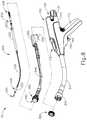
- FIG. 8depicts an exploded perspective view of the circular stapler of FIG. 1 , with portions of the shaft assembly shown separately from each other;
- FIG. 9depicts a perspective view of the handle assembly of the circular stapler of FIG. 1 , with a housing half omitted to reveal internal components of the handle assembly;
- FIG. 10depicts a perspective view of a bracket of the handle assembly of FIG. 9 ;
- FIG. 11depicts a perspective view of an indicator member of the handle assembly of FIG. 9 ;
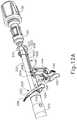
- FIG. 12Adepicts a perspective view of an anvil actuation assembly of the circular stapler of FIG. 1 , an actuation rod in a first position;
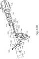
- FIG. 12Bdepicts a perspective view of the anvil actuation assembly of FIG. 12A , with the actuation rod moved to a second position to engage the bracket of FIG. 10 ;
- FIG. 12Cdepicts a perspective view of the anvil actuation assembly of FIG. 12A , with the actuation rod moved to a third position to retract the bracket of FIG. 10 proximally;
- FIG. 12Ddepicts a perspective view of the anvil actuation assembly of FIG. 12A , with a safety trigger pivoted from a first position to a second position;
- FIG. 12Edepicts a perspective view of the anvil actuation assembly of FIG. 12A , with a firing trigger pivoted from a first position to a second position;
- FIG. 13depicts a perspective view of a stapling head actuation assembly of the circular stapler of FIG. 1 ;
- FIG. 14depicts a perspective view of a cam follower of the stapling head actuation assembly of FIG. 13 ;
- FIG. 15depicts another perspective view of the cam follower of FIG. 14 ;
- FIG. 16depicts a perspective view of a rotary cam of the stapling head actuation assembly of FIG. 13 ;
- FIG. 17depicts another perspective view of the rotary cam of FIG. 16 ;
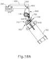
- FIG. 18Adepicts a side elevational view of the stapling head actuation assembly of FIG. 13 , with the rotary cam in a first angular position and the cam follower in a first pivotal position;
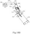
- FIG. 18Bdepicts a side elevational view of the stapling head actuation assembly of FIG. 13 , with the rotary cam in a second angular position and the cam follower in a second pivotal position;
- FIG. 19Adepicts a perspective view of the rotary cam of FIG. 16 , a rocker member, and a stop switch, with the rotary cam in a first angular position and the rocker member in a first pivotal position;
- FIG. 19Bdepicts a perspective view of the rotary cam of FIG. 16 , the rocker member of FIG. 19A , and the stop switch of FIG. 19A , with the rotary cam in a fourth angular position and the rocker member in a second pivotal position;
- FIG. 20Adepicts a schematic end view of the rotary cam of FIG. 16 , the cam follower of FIG. 14 , and the rocker member of FIG. 19A , with the rotary cam in the first angular position, the cam follower in the first pivotal position, and the rocker member in the first pivotal position;
- FIG. 20Bdepicts a schematic end view of the rotary cam of FIG. 16 and the cam follower of FIG. 14 , with the rotary cam in the second angular position, the cam follower in the second pivotal position, and the rocker member of FIG. 19A in the first pivotal position;
- FIG. 20Cdepicts a schematic end view of the rotary cam of FIG. 16 and the cam follower of FIG. 14 , with the rotary cam in a third angular position, the cam follower in the second pivotal position, and the rocker member of FIG. 19A in the first pivotal position;
- FIG. 20Ddepicts a schematic end view of the rotary cam of FIG. 16 , the cam follower of FIG. 14 , and the rocker member of FIG. 19A , with the rotary cam in a fourth angular position, the cam follower in a third pivotal position, and the rocker member in a second pivotal position;
- FIG. 21Adepicts a cross-sectional side view of the anvil of FIG. 3 positioned within a first section of a digestive tract and the stapling head assembly of FIG. 6 positioned in a second section of the digestive tract, with the anvil separated from the stapling head assembly;
- FIG. 21Bdepicts a cross-sectional side view of the anvil of FIG. 3 positioned within the first section of the digestive tract and the stapling head assembly of FIG. 6 positioned in the second section of the digestive tract, with the anvil secured to the stapling head assembly;
- FIG. 21Cdepicts a cross-sectional side view of the anvil of FIG. 3 positioned within the first section of the digestive tract and the stapling head assembly of FIG. 6 positioned in the second section of the digestive tract, with the anvil retracted toward the stapling head assembly to thereby clamp tissue between the anvil and the stapling head assembly;
- FIG. 21Ddepicts a cross-sectional side view of the anvil of FIG. 3 positioned within the first section of the digestive tract and the stapling head assembly of FIG. 6 positioned in the second section of the digestive tract, with the stapling head assembly actuated to sever and staple the clamped tissue;
- FIG. 21Edepicts a cross-sectional side view of the first and second sections of the digestive tract of FIG. 21A joined together at an end-to-end anastomosis.
- FIG. 22depicts a side cut-away view of a handle assembly of an exemplary alternative circular stapler
- FIG. 23depicts a side elevational view of an anvil lockout assembly of the handle assembly of FIG. 22 , with the anvil lockout assembly in an unlocked position;
- FIG. 24depicts another side elevational view of the anvil lockout assembly of FIG. 23 , with the anvil lockout assembly in a locked position;
- FIG. 25depicts a detailed side elevational view of the anvil lockout assembly of FIG. 23 , with the anvil lockout assembly in the unlocked position;
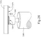
- FIG. 26depicts another detailed side elevational view of the anvil lockout assembly of FIG. 23 , with the anvil lockout assembly in the locked position;
- FIG. 27depicts a detailed perspective cut-away view of a handle assembly of another exemplary alternative circular stapler
- FIG. 28depicts a detailed perspective view of an anvil actuation assembly of the handle assembly of FIG. 27 ;
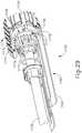
- FIG. 29depicts a detailed perspective view of an anvil lockout assembly of the anvil actuation assembly of FIG. 28 , with the anvil lockout assembly in an unlocked position;
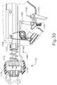
- FIG. 30depicts a detailed side elevational view of the anvil actuation assembly of FIG. 28 , with the anvil lockout assembly of FIG. 29 in the unlocked position;
- FIG. 31depicts another detailed side elevational view of the anvil actuation assembly of FIG. 28 , with the anvil lockout assembly of FIG. 29 in a locked position;
- FIG. 32depicts a detailed perspective view of an alternative configuration of the anvil lockout assembly of FIG. 29 ;
- FIG. 33depicts a detailed perspective cut-away view of yet another exemplary alternative anvil lockout assembly
- FIG. 34depicts a detailed side elevational view of the anvil lockout assembly of FIG. 33 , with the anvil lockout assembly in an intermediate state between an unlocked position and a locked position;
- FIG. 35depicts another detailed side elevational view of the anvil lockout assembly of FIG. 33 , with the anvil lockout assembly in the locked position;
- FIG. 36depicts a detailed side elevational view of an exemplary variation of the anvil lockout assembly of FIG. 33 , with the anvil lockout assembly in an unlocked position;
- FIG. 37depicts a detailed perspective cut-away view of yet another exemplary alternative anvil lockout assembly
- FIG. 38depicts a detailed side elevational view of the anvil lockout assembly of FIG. 37 , with the anvil lockout assembly in an unlocked position;
- FIG. 39depicts another detailed side elevational view of the anvil lockout assembly of FIG. 37 , with the anvil lockout assembly in a locked position;
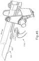
- FIG. 40depicts a side elevational view of an exemplary alternative set of triggers that may be readily incorporated into the circular staplers of FIGS. 1, 22, 27, 33 and 37 ;
- FIG. 41depicts another side elevational view of the triggers of FIG. 40 , with a safety trigger engaged;
- FIG. 42depicts another side elevational view of the triggers of FIG. 40 , with a firing trigger advanced to an activation position and engaged with the safety trigger;
- FIG. 43depicts still another side elevational view of the triggers of FIG. 40 , with the firing trigger returning the safety trigger to an initial position;
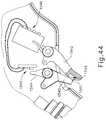
- FIG. 44depicts a side elevational view of another exemplary alternative set of triggers that may be readily incorporated into the circular staplers of FIGS. 1, 22, 27, 33 , and 37 ;
- FIG. 45depicts a detailed perspective view of the anvil actuation assembly of FIG. 12A , with the anvil actuation assembly equipped with a firing lockout assembly;
- FIG. 46depicts a detailed perspective view of the anvil actuation assembly of FIG. 12A , with the anvil actuation assembly equipped with an alternative firing lockout assembly.
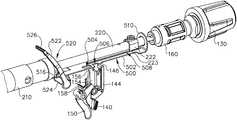
- FIGS. 1-2depict an exemplary surgical circular stapling instrument ( 10 ) that may be used to provide an end-to-end anastomosis between two sections of an anatomical lumen such as a portion of a patient's digestive tract.
- Instrument ( 10 ) of this examplecomprises a handle assembly ( 100 ), a shaft assembly ( 200 ), a stapling head assembly ( 300 ), and an anvil ( 400 ).
- Handle assembly ( 100 )comprises a casing ( 110 ) defining an obliquely oriented pistol grip ( 112 ).
- pistol grip ( 112 )is perpendicularly oriented.
- pistol grip ( 112 )is omitted.
- Handle assembly ( 110 )further includes a window ( 114 ) that permits viewing of a movable indicator needle ( 526 ) as will be described in greater detail below.
- a series of hash marks, colored regions, and/or other fixed indicatorsare positioned adjacent to window ( 114 ) in order to provide a visual context for indicator needle ( 526 ), thereby facilitating operator evaluation of the position of needle ( 526 ) within window ( 114 ).
- Various suitable alternative features and configurations for handle assembly ( 112 )will be apparent to those of ordinary skill in the art in view of the teachings herein.
- Instrument ( 10 ) of the present examplefurther includes a battery pack ( 120 ).
- Battery pack ( 120 )is operable to provide electrical power to a motor ( 160 ) in pistol grip ( 112 ) as will be described in greater detail below.
- Battery pack ( 120 )is removable from handle assembly ( 100 ).
- battery pack ( 120 )may be inserted into a socket ( 116 ) defined by casing ( 110 ). Once battery pack ( 120 ) is fully inserted in socket ( 116 ), latches ( 122 ) of battery pack ( 120 ) may resiliently engage interior features of casing ( 110 ) to provide a snap fit.
- battery pack ( 120 )may have complementary electrical contacts, pins and sockets, and/or other features that provide paths for electrical communication from battery pack ( 120 ) to electrically powered components in handle assembly ( 100 ) when battery pack ( 120 ) is inserted in socket ( 116 ). It should also be understood that, in some versions, battery pack ( 120 ) is unitarily incorporated within handle assembly ( 100 ) such that battery back ( 120 ) cannot be removed from handle assembly ( 100 ).
- Shaft assembly ( 200 )extends distally from handle assembly ( 100 ) and includes a preformed bend.
- the preformed bendis configured to facilitate positioning of stapling head assembly ( 300 ) within a patient's colon.
- shaft assembly ( 200 )is straight, such that shaft assembly ( 200 ) lacks a preformed bend.
- Various exemplary components that may be incorporated into shaft assembly ( 100 )will be described in greater detail below.
- Stapling head assembly ( 300 )is located at the distal end of shaft assembly ( 200 ). As shown in FIGS. 1-2 and as will be described in greater detail below, anvil ( 400 ) is configured to removably couple with shaft assembly ( 200 ), adjacent to stapling head assembly ( 300 ). As will also be described in greater detail below, anvil ( 400 ) and stapling head assembly ( 300 ) are configured to cooperate to manipulate tissue in three ways, including clamping the tissue, cutting the tissue, and stapling the tissue.
- a knob ( 130 ) at the proximal end of handle assembly ( 100 )is rotatable relative to casing ( 110 ) to provide precise clamping of the tissue between anvil ( 400 ) and stapling head assembly ( 300 ). When a safety trigger ( 140 ) of handle assembly ( 100 ) is pivoted away from a firing trigger ( 150 ) of handle assembly ( 100 ), firing trigger ( 150 ) may be actuated to thereby provide cutting and stapling of the tissue.
- distal and proximalwill be used with reference to the orientation of anvil ( 400 ) when anvil ( 400 ) is coupled with shaft assembly ( 200 ) of instrument ( 10 ).
- proximal features of anvil ( 400 )will be closer to the operator of instrument ( 10 ); while distal features of anvil ( 400 ) will be further from the operator of instrument ( 10 ).
- anvil ( 400 ) of the present examplecomprises a head ( 410 ) and a shank ( 420 ).
- Head ( 410 )includes a proximal surface ( 412 ) that defines a plurality of staple forming pockets ( 414 ).
- Staple forming pockets ( 414 )are arranged in two concentric annular arrays. In some other versions, staple forming pockets ( 414 ) are arranged in three or more concentric annular arrays. Staple forming pockets ( 414 ) are configured to deform staples as the staples are driven into staple forming pockets ( 414 ).
- each staple forming pocket ( 414 )may deform a generally “U” shaped staple into a “B” shape as is known in the art.
- proximal surface ( 412 )terminates at an inner edge ( 416 ), which defines an outer boundary of an annular recess ( 418 ) surrounding shank ( 420 ).
- Shank ( 420 )defines a bore ( 422 ) and includes a pair of pivoting latch members ( 430 ) positioned in bore ( 422 ).
- each latch member ( 430 )includes a “T” shaped distal end ( 432 ), a rounded proximal end ( 434 ), and a latch shelf ( 436 ) located distal to proximal end ( 434 ). “T” shaped distal ends ( 432 ) secure latch members ( 430 ) within bore ( 422 ).
- Latch members ( 430 )are positioned within bore ( 422 ) such that distal ends ( 434 ) are positioned at the proximal ends of lateral openings ( 424 ), which are formed through the sidewall of shank ( 420 ). Lateral openings ( 424 ) thus provide clearance for distal ends ( 434 ) and latch shelves ( 436 ) to deflect radially outwardly from the longitudinal axis defined by shank ( 420 ).
- latch members ( 430 )are configured to resiliently bias distal ends ( 434 ) and latch shelves ( 436 ) to radially inwardly toward the longitudinal axis defined by shank ( 420 ). Latch members ( 430 ) thus act as retaining clips.
- anvil ( 400 )to be removably secured to a trocar ( 330 ) of stapling head assembly ( 300 ) as will be described in greater detail below. It should be understood, however, that latch members ( 436 ) are merely optional. Anvil ( 400 ) may be removably secured to a trocar ( 330 ) using any other suitable components, features, or techniques.
- anvil ( 400 )may be further constructed and operable in accordance with at least some of the teachings of U.S. Pat. Nos. 5,205,459; 5,271,544; 5,275,322; 5,285,945; 5,292,053; 5,333,773; 5,350,104; 5,533,661; and/or U.S. Pat. No. 8,910,847, the disclosures of which are incorporated by reference herein. Still other suitable configurations will be apparent to one of ordinary skill in the art in view of the teachings herein.
- stapling head assembly ( 300 ) of the present exampleis coupled to a distal end of shaft assembly ( 200 ) and comprises a tubular casing ( 310 ) housing a slidable staple driver member ( 350 ).
- a cylindraceous inner core member ( 312 )extends distally within tubular casing ( 310 ).
- Tubular casing ( 310 )is fixedly secured to an outer sheath ( 210 ) of shaft assembly ( 200 ), such that tubular casing ( 310 ) serves as a mechanical ground for stapling head assembly ( 300 ).
- Trocar ( 330 )is positioned coaxially within inner core member ( 312 ) of tubular casing ( 310 ). As will be described in greater detail below, trocar ( 330 ) is operable to translate distally and proximally relative to tubular casing ( 310 ) in response to rotation of knob ( 130 ) relative to casing ( 110 ) of handle assembly ( 100 ).
- Trocar ( 330 )comprises a shaft ( 332 ) and a head ( 334 ). Head ( 334 ) includes a pointed tip ( 336 ) and an inwardly extending proximal surface ( 338 ).
- Shaft ( 332 )thus provides a reduced outer diameter just proximal to head ( 334 ), with surface ( 338 ) providing a transition between that reduced outer diameter of shaft ( 332 ) and the outer diameter of head ( 334 ). While tip ( 336 ) is pointed in the present example, tip ( 336 ) is not sharp. Tip ( 336 ) will thus not easily cause trauma to tissue due to inadvertent contact with tissue. Head ( 334 ) and the distal portion of shaft ( 332 ) are configured for insertion in bore ( 422 ) of anvil ( 420 ).
- Proximal surface ( 338 ) and latch shelves ( 436 )have complementary positions and configurations such that latch shelves ( 436 ) engage proximal surface ( 338 ) when shank ( 420 ) of anvil ( 400 ) is fully seated on trocar ( 330 ). Anvil ( 400 ) is thus secured to trocar ( 330 ) through a snap fit due to latch members ( 430 ).
- Staple driver member ( 350 )is operable to actuate longitudinally within tubular casing ( 310 ) in response to activation of motor ( 160 ) as will be described in greater detail below.
- Staple driver member ( 350 )includes two distally presented concentric annular arrays of staple drivers ( 352 ).
- Staple drivers ( 352 )are arranged to correspond with the arrangement of staple forming pockets ( 414 ) described above.
- each staple driver ( 352 )is configured to drive a corresponding staple into a corresponding staple forming pocket ( 414 ) when stapling head assembly ( 300 ) is actuated.
- the arrangement of staple drivers ( 352 )may be modified just like the arrangement of staple forming pockets ( 414 ) as described above.
- Staple driver member ( 350 )also defines a bore ( 354 ) that is configured to coaxially receive core member ( 312 ) of tubular casing ( 310 ).
- An annular array of studs ( 356 )project distally from a distally presented surface surrounding bore ( 354 ).
- Knife member ( 340 )is coaxially positioned within staple driver member ( 350 ).
- Knife member ( 340 )includes a distally presented, sharp circular cutting edge ( 342 ).
- Knife member ( 340 )is sized such that knife member ( 340 ) defines an outer diameter that is smaller than the diameter defined by the inner annular array of staple drivers ( 352 ).
- Knife member ( 340 )also defines an opening that is configured to coaxially receive core member ( 312 ) of tubular casing ( 310 ).
- An annular array of openings ( 346 ) formed in knife member ( 340 )is configured to complement the annular array of studs ( 356 ) of staple driver member ( 350 ), such that knife member ( 340 ) is fixedly secured to staple driver member ( 350 ) via studs ( 356 ) and openings ( 346 ).
- Other suitable structural relationships between knife member ( 340 ) and stapler driver member ( 350 )will be apparent to those of ordinary skill in the art in view of the teachings herein.
- a deck member ( 320 )is fixedly secured to tubular casing ( 310 ).
- Deck member ( 320 )includes a distally presented deck surface ( 322 ) defining two concentric annular arrays of staple openings ( 324 ).
- Staple openings ( 324 )are arranged to correspond with the arrangement of staple drivers ( 352 ) and staple forming pockets ( 414 ) described above.
- each staple opening ( 324 )is configured to provide a path for a corresponding staple driver ( 352 ) to drive a corresponding staple through deck member ( 320 ) and into a corresponding staple forming pocket ( 414 ) when stapling head assembly ( 300 ) is actuated.
- the arrangement of staple openings ( 322 )may be modified just like the arrangement of staple forming pockets ( 414 ) as described above. It should also be understood that various structures and techniques may be used to contain staples within stapling head assembly ( 300 ) before stapling head assembly ( 300 ) is actuated. Such structures and techniques that are used to contain staples within stapling head assembly ( 300 ) may prevent the staples from inadvertently falling out through staple openings ( 324 ) before stapling head assembly ( 300 ) is actuated. Various suitable forms that such structures and techniques may take will be apparent to those of ordinary skill in the art in view of the teachings herein.
- deck member ( 320 )defines an inner diameter that is just slightly larger than the outer diameter defined by knife member ( 340 ). Deck member ( 320 ) is thus configured to allow knife member ( 340 ) to translate distally to a point where cutting edge ( 342 ) is distal to deck surface ( 322 ).
- stapling head assembly ( 300 )may be further constructed and operable in accordance with at least some of the teachings of U.S. Pat. Nos. 5,205,459; 5,271,544; 5,275,322; 5,285,945; 5,292,053; 5,333,773; 5,350,104; 5,533,661; and/or U.S. Pat. No. 8,910,847, the disclosures of which are incorporated by reference herein. Still other suitable configurations will be apparent to one of ordinary skill in the art in view of the teachings herein.
- FIG. 8shows various components of shaft assembly ( 200 ), which couples components of stapling head assembly ( 300 ) with components of handle assembly ( 100 ).
- shaft assembly ( 200 )includes an outer sheath ( 210 ) that extends between handle assembly ( 100 ) and tubular casing ( 310 ).
- outer sheath ( 210 )is rigid and includes a preformed curved section as noted above.
- Shaft assembly ( 200 )further includes a trocar actuation rod ( 220 ) and a trocar actuation band assembly ( 230 ).
- the distal end of trocar actuation band assembly ( 230 )is fixedly secured to the proximal end of trocar shaft ( 332 ).
- the proximal end of trocar actuation band assembly ( 230 )is fixedly secured to the distal end of trocar actuation rod ( 220 ). It should therefore be understood that trocar ( 330 ) will translate longitudinally relative to outer sheath ( 210 ) in response to translation of trocar actuation band assembly ( 230 ) and trocar actuation rod ( 220 ) relative to outer sheath ( 210 ).
- Trocar actuation band assembly ( 230 )is configured to flex such that trocar actuation band assembly ( 230 ) may follow along the preformed curve in shaft assembly ( 200 ) as trocar actuation band assembly ( 230 ) is translated longitudinally relative to outer sheath ( 210 ).
- trocar actuation band assembly ( 230 )has sufficient column strength and tensile strength to transfer distal and proximal forces from trocar actuation rod ( 220 ) to trocar shaft ( 332 ).
- Trocar actuation rod ( 220 )is rigid.
- a clip ( 222 )is fixedly secured to trocar actuation rod ( 220 ) and is configured to cooperate with complementary features within handle assembly ( 100 ) to prevent trocar actuation rod ( 220 ) from rotating within handle assembly ( 100 ) while still permitting trocar actuation rod ( 220 ) to translate longitudinally within handle assembly ( 100 ).
- Trocar actuation rod ( 220 )further includes a coarse helical threading ( 224 ) and a fine helical threading ( 226 ). Details regarding the movement of trocar actuation rod ( 220 ) will be described in greater detail below.
- Shaft assembly ( 200 )further includes a stapling head assembly driver ( 240 ) that is slidably received within outer sheath ( 210 ).
- the distal end of stapling head assembly driver ( 240 )is fixedly secured to the proximal end of staple driver member ( 350 ).
- the proximal end of stapling head assembly driver ( 240 )is secured to a drive bracket ( 250 ) via a pin ( 242 ). It should therefore be understood that staple driver member ( 350 ) will translate longitudinally relative to outer sheath ( 210 ) in response to translation of stapling head assembly driver ( 240 ) and drive bracket ( 250 ) relative to outer sheath ( 210 ).
- Stapling head assembly driver ( 240 )is configured to flex such that stapling head assembly driver ( 240 ) may follow along the preformed curve in shaft assembly ( 200 ) as stapling head assembly driver ( 240 ) is translated longitudinally relative to outer sheath ( 210 ). However, stapling head assembly driver ( 240 ) has sufficient column strength to transfer distal forces from drive bracket ( 250 ) to staple driver member ( 350 ). Details regarding the movement of drive bracket ( 250 ) will be described in greater detail below.
- shaft assembly ( 200 )may further include one or more spacer elements within outer sheath ( 210 ). Such spacer elements may be configured to support trocar actuation band assembly ( 230 ) and/or stapling head assembly driver ( 240 ) as trocar actuation band assembly ( 230 ) and/or stapling head assembly driver ( 240 ) translate through outer sheath ( 210 ).
- such spacer elementsmay prevent trocar actuation band assembly ( 230 ) and/or stapling head assembly driver ( 240 ) from buckling as trocar actuation band assembly ( 230 ) and/or stapling head assembly driver ( 240 ) translate through outer sheath ( 210 ).
- trocar actuation band assembly ( 230 ) and/or stapling head assembly driver ( 240 )may prevent trocar actuation band assembly ( 230 ) and/or stapling head assembly driver ( 240 ) from buckling as trocar actuation band assembly ( 230 ) and/or stapling head assembly driver ( 240 ) translate through outer sheath ( 210 ).
- Various suitable forms that such spacer elements may takewill be apparent to those of ordinary skill in the art in view of the teachings herein.
- shaft assembly ( 200 )may be further constructed and operable in accordance with at least some of the teachings of U.S. Pat. Nos. 5,205,459; 5,271,544; 5,275,322; 5,285,945; 5,292,053; 5,333,773; 5,350,104; 5,533,661; and/or U.S. Pat. No. 8,910,847, the disclosures of which are incorporated by reference herein. Still other suitable configurations will be apparent to one of ordinary skill in the art in view of the teachings herein.
- handle assembly ( 100 )includes several components that are operable to actuate anvil ( 400 ) and stapling head assembly ( 300 ). Handle assembly ( 100 ) also includes components that are operable to selectively lock out triggers ( 140 , 150 ) based on the position of anvil ( 400 ) relative to stapling head assembly ( 300 ). When triggers ( 140 , 150 ) are locked out, firing trigger ( 150 ) is prevented from initiating actuation of stapling head assembly ( 300 ). Thus, trigger ( 150 ) is only operable to initiate actuation of stapling head assembly ( 300 ) when the position of anvil ( 400 ) relative to stapling head assembly ( 300 ) is within a predefined range.
- the components of handle assembly ( 100 )that provide the foregoing operability will be described in greater detail below.
- Knob ( 130 )protrudes proximally from casing ( 110 ) of handle assembly and is rotatable relative to casing ( 110 ). As shown in FIG. 9 , a nut ( 160 ) is secured to the distal end of knob ( 130 ). In the present example, nut ( 160 ) is fixedly secured to the distal end of knob ( 130 ) such that nut ( 160 ) will rotate unitarily with knob ( 130 ). Nut ( 160 ) and knob ( 130 ) are configured to cooperate with trocar actuation rod ( 220 ) to thereby translate trocar actuation rod ( 220 ) longitudinally relative to casing ( 110 ) in response to rotation of nut ( 160 ) and knob ( 130 ) relative to casing ( 110 ). As noted above, trocar ( 330 ) will translate longitudinally relative to outer sheath ( 210 ) in response to translation of trocar actuation rod ( 220 ) relative to outer sheath ( 210 ) and casing ( 110 ).
- trocar actuation rod ( 220 )The proximal portion of trocar actuation rod ( 220 ) is positioned within handle assembly ( 100 ) to engage nut ( 160 ) and knob ( 130 ).
- trocar actuation rod ( 220 )is positioned within handle assembly ( 100 ) such that coarse helical threading ( 224 ) will selectively engage a thread engagement feature (not shown) within the interior of nut ( 160 ); and such that fine helical threading ( 226 ) will selectively engage a thread engagement feature (not shown) within the interior of knob ( 130 ).
- the thread engagement feature of nut ( 160 )comprises an inwardly directed tab; while the thread engagement feature of knob ( 130 ) comprises a helical threading.
- Other suitable forms that such thread engagement features may takewill be apparent to those of ordinary skill in the art in view of the teachings herein.
- trocar actuation rod ( 220 )travels proximally through a first range of longitudinal motion where coarse helical threading ( 224 ) is engaged with nut ( 160 ) to provide a relatively rapid rate of translation. Fine helical threading ( 226 ) is not engaged with knob ( 130 ) during this range of motion.
- trocar actuation rod ( 220 )When nut ( 160 ) and knob ( 130 ) are further rotated relative to casing ( 110 ) after trocar actuation rod ( 220 ) completes the first range of motion, trocar actuation rod ( 220 ) will continue to travel proximally through a second range of longitudinal motion where fine helical threading ( 226 ) is engaged with knob ( 130 ) to provide a relatively slow rate of translation. Thus, trocar actuation rod ( 220 ) will translate proximally through a sequence of rapid translation followed by slow translation, based on engagement between coarse helical threading ( 224 ) and nut ( 160 ) followed by engagement between fine helical threading ( 226 ) and knob ( 130 ).
- knob ( 130 )when anvil ( 400 ) is coupled with trocar ( 330 ), rotation of knob ( 130 ) will provide corresponding translation of anvil relative to stapling head assembly ( 300 ). It should also be understood that knob ( 130 ) may be rotated in a first angular direction (e.g., clockwise) to retract anvil ( 400 ) toward stapling head assembly ( 300 ); and in a second angular direction (e.g., counterclockwise) to advance anvil ( 400 ) away from stapling head assembly ( 300 ).
- first angular directione.g., clockwise
- a second angular directione.g., counterclockwise
- Knob ( 130 )may thus be used to adjust the gap distance (d) between opposing surfaces ( 412 , 322 ) of anvil ( 400 ) and stapling head assembly ( 300 ) until a suitable gap distance (d) has been achieved as shown in FIG. 21C and as described in greater detail below.
- knobmay be used to adjust the gap distance (d) between opposing surfaces ( 412 , 322 ) of anvil ( 400 ) and stapling head assembly ( 300 ).
- Setting an appropriate gap distance (d) before actuating stapling head assembly ( 300 )may be critical to the success of an anastomosis. For instance, if the gap distance (d) is too great, the staples that are deployed at the anastomosis site may not be sufficiently formed by staple forming pockets ( 414 ). This may result in leakage at the anastomosis site, and in some cases may ultimately lead to the separation of the anatomical lumen sections that are joined at the anastomosis site.
- the gap distance (d)is too small, the internal structure of the tissue compressed between surfaces ( 412 , 322 ) may be damaged to the point where the structural integrity of the tissue is compromised. This may prevent the tissue from adequately holding the formed staples, which again may result in leakage or other failure of the anastomosis. It may therefore be desirable to provide the operator with some form of feedback indicating whether the gap distance (d) is within an appropriate range. It may also be desirable to prevent the operator from actuating stapling head assembly ( 300 ) unless the gap distance (d) is within an appropriate range.
- FIGS. 9-12Eshow components that provide feedback to the operator to indicate whether the gap distance (d) is within an appropriate range; and prevent the operator from actuating stapling head assembly ( 300 ) unless the gap distance (d) is within an appropriate range.
- a bracket ( 500 )is configured and positioned to move in response to movement of trocar actuation rod ( 220 ).
- bracket ( 500 )includes a rigid body ( 502 ) that defines a first slot ( 504 ), a second slot ( 506 ), and a third slot ( 508 ).
- An upright feature ( 510 )is positioned at the proximal end of body ( 502 ) and defines an opening ( 512 ).
- Trocar actuation rod ( 220 )extends coaxially through opening ( 512 ).
- a coil spring ( 170 )is interposed between the proximal end of upright feature ( 510 ) and a rigid bulkhead feature that is defined by casing ( 110 ) and that forms a support journal for nut ( 160 ).
- the bulkheadis fixed within casing ( 110 ) and thereby provides a ground for the proximal end of coil spring ( 170 ), such that coil spring ( 170 ) resiliently imparts a distal bias to bracket ( 500 ) via upright feature ( 510 ).
- Bracket ( 500 )further includes a laterally presented flange ( 516 ) at the distal end of body ( 502 ). Flange ( 516 ) defines a slot ( 514 ).
- an indicator member ( 520 )is configured to pivot in response to translation of bracket ( 500 ).
- indicator member ( 520 )comprises an upright arm ( 522 ), a snap pin ( 524 ) projecting laterally from a lower end of arm ( 522 ), an indicator needle ( 526 ) projecting laterally from an upper end of arm ( 522 ), and a coupling pin ( 528 ) projecting laterally from an intermediate region of arm ( 522 ).
- Snap pin ( 524 )is configured to snap into a complementary recess provided by casing ( 110 ).
- Snap pin ( 524 )thereby secures indicator member ( 520 ) to casing ( 110 ) yet permits indicator member ( 520 ) to pivot relative to casing ( 110 ) about the longitudinal axis of snap pin ( 524 ).
- Indicator needle ( 526 )is positioned to be visible through window ( 114 ) of handle assembly ( 110 ) to thereby visually indicate the pivotal position of indicator member ( 520 ).
- Coupling pin ( 528 )is slidably received in slot ( 514 ) of flange ( 516 ) of bracket ( 500 ). This engagement between indicator member ( 520 ), casing ( 110 ), and bracket ( 500 ) provides pivotal movement of indicator member ( 520 ) in response to translation of bracket ( 500 ).
- Bracket ( 500 )is configured to selectively prevent and permit actuation of triggers ( 140 , 150 ).
- slots ( 504 , 506 ) of bracket ( 500 )are configured to selectively provide clearance for actuation of triggers ( 140 , 150 ).
- safety trigger ( 140 )is pivotably coupled with a first upright member ( 144 ).
- First upright member ( 144 )is coupled with casing ( 110 ) such that first upright member ( 144 ) is configured to translate upwardly in response to pivoting of safety trigger ( 140 ) toward pistol grip ( 112 ).
- body ( 502 ) of bracket ( 500 )is configured to prevent this movement of first upright member ( 144 ) and safety trigger ( 140 ) by engaging the upper end ( 146 ) of first upright member ( 144 ).
- Body ( 502 )thus blocks movement of first upright member ( 144 ) and safety trigger ( 140 ) until bracket ( 500 ) is moved to a position where slot ( 506 ) is aligned with upper end ( 146 ) to thereby provide clearance for upward movement of first upright member ( 144 ).
- safety trigger ( 140 )cannot be pivoted toward pistol grip ( 112 ) until slot ( 506 ) is positioned over upper end ( 146 ).
- firing trigger ( 150 )is pivotably coupled with a second upright member ( 154 ).
- Second upright member ( 154 )is coupled with casing ( 110 ) such that second upright member ( 154 ) is configured to translate upwardly in response to pivoting of safety trigger ( 150 ) toward pistol grip ( 112 ).
- body ( 502 ) of bracket ( 500 )is configured to prevent this movement of second upright member ( 154 ) and firing trigger ( 150 ) by engaging the upper end ( 156 ) of second upright member ( 154 ).
- safety trigger ( 140 )Even if safety trigger ( 140 ) is pivoted out of the way to otherwise permit movement of firing trigger ( 150 ), body ( 502 ) blocks movement of second upright member ( 154 ) and firing trigger ( 150 ) until bracket ( 500 ) is moved to a position where slot ( 504 ) is aligned with upper end ( 156 ) to thereby provide clearance for upward movement of second upright member ( 154 ). It should therefore be understood that, even if safety trigger ( 140 ) is pivoted out of the way to otherwise permit movement of firing trigger ( 150 ), firing trigger ( 150 ) cannot be pivoted toward pistol grip ( 112 ) until slot ( 504 ) is positioned over upper end ( 156 ).
- Third slot ( 508 )is configured to receive a downwardly projecting boss ( 223 ) of clip ( 222 ), which is rigidly secured to trocar actuation rod ( 220 ). While casing ( 110 ) is configured to allow bracket ( 500 ) to translate longitudinally within casing ( 110 ), casing ( 110 ) includes rails, channels, and/or other features that prevent bracket ( 500 ) from rotating within casing ( 110 ). Thus, the positioning of boss ( 223 ) in slot ( 508 ) prevents clip ( 222 ) and trocar actuation rod ( 220 ) from rotating within casing ( 110 ). Boss ( 223 ) and slot ( 508 ) nevertheless allow bracket ( 500 ) to translate longitudinally within casing ( 110 ) as will be described in greater detail below.
- FIGS. 12A-12Edepict the above-described components at various stages of operation.
- trocar actuation rod ( 220 )is in a distal-most position, such that trocar ( 330 ) is in a distal-most position.
- the operatormay couple anvil ( 400 ) with trocar ( 330 ) by inserting trocar ( 330 ) into bore ( 422 ) until latch members ( 430 ) are secured to head ( 334 ) of trocar ( 330 ). The operator then rotates knob ( 130 ), which rotates nut ( 160 ).
- trocar actuation rod ( 220 )As knob ( 130 ) and nut ( 160 ) rotate, engagement between coarse helical threading ( 224 ) of trocar actuation rod ( 220 ) and the complementary feature of nut ( 160 ) causes trocar actuation rod ( 220 ) to retract proximally at a relatively rapid rate, such that trocar actuation rod ( 220 ) reaches the position shown in FIG. 12B . This provides proximal retraction of trocar actuation rod ( 220 ) provides retraction of trocar ( 330 ) and anvil ( 400 ). As trocar actuation rod ( 220 ) moves from the position shown in FIG. 12A to the position shown in FIG. 12B , bracket ( 500 ) remains stationary.
- the operatormay continue rotating knob ( 130 ) and nut ( 160 ), which causes further proximal retraction of trocar actuation rod ( 220 ) as shown in FIG. 12C .
- This of coursecauses further proximal retraction of trocar ( 330 ) and anvil ( 400 ).
- clip ( 222 )bears against bracket ( 500 ), driving bracket ( 500 ) proximally.
- This proximal movement of bracket ( 500 )causes indicator member ( 520 ) to pivot from the position shown in FIG. 12B to the position shown in FIG. 12C due to the positioning of pin ( 528 ) in slot ( 514 ) of flange ( 516 ).
- indicator member ( 520 )pivots from the position shown in FIG. 12B to the position shown in FIG. 12C , the operator may observe the position of indicator needle ( 526 ) through window ( 114 ) of handle assembly ( 110 ).
- a series of hash marks, colored regions, and/or other fixed indicatorsmay be positioned adjacent to window ( 114 ) in order to provide a visual context for indicator needle ( 526 ), thereby facilitating operator evaluation of the position of needle ( 526 ) within window ( 114 ). It should be understood that the position of needle ( 526 ) within window ( 114 ) will be indicative of the longitudinal position of trocar ( 330 ) and anvil ( 400 ).
- the position of needle ( 526 ) within window ( 114 )will thus indicate the gap distance (d) between opposing surfaces ( 412 , 322 ) of anvil ( 400 ) and stapling head assembly ( 300 ). While observing the position of needle ( 526 ) within window ( 114 ), the operator may rotate knob ( 130 ) clockwise or counterclockwise to further retract or advance trocar ( 330 ) and anvil ( 400 ), thereby providing fine adjustment of the gap distance (d) until a desired gap distance (d) is reached within an appropriate range.
- trocar actuation rod ( 220 )will be at a longitudinal position where fine helical threading ( 226 ) is engaged with a complementary feature of knob ( 130 ) and coarse helical threading ( 224 ) is disengaged from the complementary feature of nut ( 160 ).
- coarse helical threading ( 224 )disengages nut ( 160 ) and fine helical threading ( 226 ) begins to engage knob ( 130 ) once trocar actuation rod ( 220 ) reaches the longitudinal position shown in FIG. 12B (i.e., when clip ( 222 ) first engages upright member ( 510 )).
- the transition from engagement by coarse helical threading ( 224 ) to fine helical threading ( 226 )occurs sometime between the stage shown in FIG. 12B and the stage shown in FIG. 12C .
- Other suitable stages at which the coarse-to-fine transition may occurwill be apparent to those of ordinary skill in the art in view of the teachings herein.
- some alternative versions of trocar actuation rod ( 220 )may have just a single threading section, with the pitch of the threading being consistent along the length of the threading. In other words, trocar actuation rod ( 220 ) does not necessarily need to have two different sections of threading ( 224 , 226 ) with different pitches.
- slot ( 506 )is aligned with upper end ( 146 ) to thereby provide clearance for upward movement of first upright member ( 144 ).
- slot ( 504 )is aligned with upper end ( 156 ) to thereby provide clearance for upward movement of second upright member ( 154 ).
- slots ( 504 , 506 )are sized and positioned such that slots ( 504 , 506 ) only provide clearance for upward movement of upright members ( 144 , 154 ) when the gap distance (d) is within a clinically acceptable range.
- a “clinically acceptable range” for the gap distance (d)may be between approximately 0.110 inches and approximately 0.040 inches.
- a “clinically acceptable range” for the gap distance (d)may be between approximately 0.110 inches and approximately 0.020 inches. Even when slots ( 504 , 506 ) are positioned to provide clearance for upward movement of upright members ( 144 , 154 ) as shown in FIG. 12C , safety trigger ( 140 ) will still block pivotal movement of firing trigger ( 150 ) about a pin ( 152 ) ( FIG. 9 ) when safety trigger ( 140 ) is in the non-actuated position shown in FIG. 12C . Thus, in order to enable movement of firing trigger ( 150 ), the operator will need to first actuate safety trigger ( 140 ) about a pin ( 142 ) ( FIG. 9 ) from the position shown in FIG. 12C to the position shown in FIG. 12D .
- upper end ( 146 )passes through slot ( 506 ) as safety trigger ( 140 ) is pivoted from the position shown in FIG. 12C to the position shown in FIG. 12D . It should be understood that this movement of upper end ( 146 ) would not be possible at the stages shown in FIGS. 12A-12B (when the gap distance (d) is too great) because body ( 502 ) would physically block upward movement of upright member ( 144 ), thereby physically blocking pivotal movement of safety trigger ( 140 ).
- a cap (not shown) incorporated into knob ( 130 )prevents knob ( 130 ) from rotating to a point where anvil ( 400 ) would be retracted too far proximally (such that the gap distance (d) is too small).
- body ( 502 )would physically block upward movement of upright member ( 144 ), thereby physically blocking pivotal movement of safety trigger ( 140 ), in the event that the operator retracts trocar ( 330 ) and anvil ( 400 ) too far proximally (such that the gap distance (d) is too small).
- instrument ( 10 )permits actuation of safety trigger ( 140 ) only when the gap distance (d) is within the clinically acceptable range.
- safety trigger ( 140 )is configured to prevent actuation of firing trigger ( 150 ) until safety trigger ( 140 ) has been actuated. Once safety trigger ( 140 ) has been actuated, the operator may actuate firing trigger ( 150 ) from the position shown in FIG. 12D to the position shown in FIG. 12E . As shown in FIG. 12E , upper end ( 156 ) passes through slot ( 504 ) as firing trigger ( 150 ) is pivoted from the position shown in FIG. 12D to the position shown in FIG. 12E . It should be understood that, even in the complete absence of safety trigger ( 140 ), this movement of upper end ( 156 ) would not be possible at the stages shown in FIGS.
- firing trigger ( 150 )may only be actuated when the gap distance (d) is within the clinically acceptable range.
- Firing trigger ( 150 ) of the present exampleincludes an integral actuation paddle ( 158 ).
- Paddle ( 158 )pivots forwardly as firing trigger ( 150 ) pivots from the position shown in FIG. 12D to the position shown in FIG. 12E .
- Paddle ( 158 )is configured to actuate a switch of a motor activation module ( 180 ), which is shown in FIG. 9 , when firing trigger ( 150 ) pivots from the position shown in FIG. 12D to the position shown in FIG. 12E .
- Motor activation module ( 180 )is in communication with battery pack ( 120 ) and motor ( 160 ), such that motor activation module ( 180 ) is configured to provide activation of motor ( 160 ) with electrical power from battery pack ( 120 ) in response to paddle ( 158 ) actuating the switch of motor activation module ( 180 ).
- motor ( 160 )will be activated when firing trigger ( 150 ) is pivoted from the position shown in FIG. 12D to the position shown in FIG. 12E . This activation of motor ( 160 ) will actuate stapling head assembly ( 300 ) as described in greater detail below.
- FIGS. 13-20Dshow various components that are operable to actuate stapling head assembly ( 300 ). These components include motor ( 160 ), a gearbox ( 162 ), a rotary cam member ( 700 ), a cam follower ( 600 ), drive bracket ( 250 ) and stapling head assembly driver ( 240 ). Gearbox ( 162 ) is coupled with a drive shaft of motor ( 160 ) and is further coupled with cam member ( 700 ). Activation of motor ( 160 ) thus causes rotation of cam member ( 700 ) via gearbox ( 162 ).
- gearbox ( 162 )Various suitable configurations that may be used for gearbox ( 162 ) will be apparent to those of ordinary skill in the art in view of the teachings herein.
- Cam member ( 700 )is configured to interact with cam follower ( 160 ) to pivot cam follower ( 160 ) in two angular directions about a pin ( 118 ) as will be described in greater detail below.
- Pin ( 118 )is coupled with casing ( 110 ).
- a bushing ( 701 )provides rotary support to cam member ( 700 ) relative to casing ( 110 ).
- Cam follower ( 600 )is pivotably coupled with drive bracket ( 250 ) via a pair of integral pins ( 602 ), which are received in complementary notches ( 252 ) of drive bracket ( 250 ).
- cam follower ( 600 )includes a first bearing feature ( 604 ) and a second bearing feature ( 610 ).
- First bearing feature ( 604 )consists of a rounded, horizontally extending surface.
- Second bearing feature ( 610 )is shaped like a quarter-pie defined by a straight vertical surface ( 612 ), a horizontally extending surface ( 614 ), and a curved surface ( 616 ). Second bearing feature ( 610 ) projects proximally relative to first bearing feature ( 504 ).
- FIGS. 16-17show cam member ( 700 ) in greater detail.
- Cam member ( 700 )comprises a distal face ( 702 ), a distally projecting post ( 704 ), and an outer circumferential surface ( 706 ).
- a first cam feature ( 710 ) and a second cam feature ( 720 )project distally from distal face ( 702 ).
- Post ( 704 )engages bushing ( 701 ).
- First cam feature ( 710 )comprises a first surface region ( 712 ), a second surface region ( 714 ), and a third surface region ( 716 ).
- First surface region ( 712 )is convexly defined by a relatively large radius of curvature, such that first surface region ( 712 ) is nearly flat.
- Second surface region ( 714 )is convexly defined by a progressively increasing radius of curvature.
- Third surface region ( 716 )is concavely defined by a relatively large radius of curvature.
- second cam feature ( 720 )projects outwardly from outer circumferential surface ( 706 ).
- Second cam feature ( 720 )includes a first surface region ( 722 ) and a second surface region ( 724 ).
- First surface region ( 722 )is substantially flat while second surface region ( 724 ) is concavely curved.
- the origin of the radius of curvature for each curved surface region ( 712 , 714 , 716 , 724 )is offset from the center of post ( 704 ).
- FIGS. 18A-18Bshow the general interaction between cam follower ( 600 ) and first and second cam features ( 710 , 720 ), though this interaction will be described in greater detail below with reference to FIGS. 20A-20D .
- cam member ( 700 )is rotated from the position shown in FIG. 18A to the position shown in FIG. 18B , first cam feature ( 710 ) bears against first bearing feature ( 604 ) of cam follower ( 600 ), causing cam follower to pivot about pin ( 118 ).
- cam follower ( 600 )pivots counterclockwise as cam member ( 700 ) is rotated from the position shown in FIG. 18A to the position shown in FIG. 18B .
- cam follower ( 600 )drives drive bracket ( 250 ) and stapling head assembly driver ( 240 ) distally, thereby actuating stapling head assembly ( 300 ).
- cam member ( 700 )continues to rotate in the same direction back toward the position shown in FIG. 18A
- second cam feature ( 720 )engages and bears against second bearing feature ( 610 ) of cam follower ( 600 ), causing cam follower ( 600 ) to pivot clockwise about pin ( 118 ).
- This clockwise pivoting of cam follower ( 600 ) about pin ( 118 )retracts drive bracket ( 250 ) and stapling head assembly driver ( 240 ) proximally back toward the position shown in FIG. 18A .
- a third cam feature ( 730 )projects outwardly from outer circumferential surface ( 706 ).
- Third cam feature ( 730 )comprises a first surface region ( 732 ) and a second surface region ( 734 ).
- First surface region ( 732 )is flat and is oriented generally tangentially relative to outer circumferential surface ( 706 ).
- Second surface region ( 732 )is also flat and is oriented radially outwardly relative to outer circumferential surface ( 706 ).
- Third cam feature ( 730 )is configured to interact with a rocker member ( 800 ) as shown in FIGS. 19A-19B .
- Rocker member ( 800 )comprises an integral pin ( 802 ), a bearing member ( 804 ), and a paddle ( 806 ).
- Pin ( 802 )is pivotably coupled with casing ( 110 ), such that rocker member ( 800 ) is pivotable within casing ( 110 ) about the longitudinal axis defined by pin ( 802 ).
- Bearing member ( 804 )is configured to interact with third cam feature ( 730 ) as will be described in greater detail below.
- Paddle ( 806 )is configured to actuate a switch button ( 192 ) of a short circuit module ( 190 ) as will also be described in greater detail below.
- FIG. 19Ashows cam member ( 700 ) in the same position as shown in FIG. 18A .
- second surface region ( 734 ) of third cam feature ( 730 )is adjacent to bearing member ( 804 ) of rocker member ( 800 ).
- FIG. 19Bshows cam member ( 700 ) in a position where cam member ( 700 ) has been rotated past the position shown in FIG. 18B and back toward the position shown in FIG. 18A .
- cam member ( 700 )has not completed a full revolution.
- first surface region ( 732 )has engaged and borne against bearing member ( 804 ), thereby pivoting rocker member ( 800 ) about the longitudinal axis defined by pin ( 802 ).
- Short circuit module ( 190 )is configured to prevent motor ( 160 ) from further activation when switch button ( 192 ) has been actuated.
- short circuit module ( 190 )couples battery pack ( 120 ) with a power sink, in addition to short circuiting motor ( 160 ), when switch button ( 192 ) is actuated. This may result in discharge of battery pack ( 120 ) in addition to stopping activation of motor ( 160 ) once an actuation stroke of stapling head assembly ( 300 ) has been completed.
- short circuit module( 190 ) may be configured and operable in accordance with at least some of the teachings of U.S. Pub. No. 2015/0083774, issued as U.S. Pat. No. 9,907,552 on Mar. 6, 2018, the disclosure of which is incorporated by reference herein.
- Other suitable configurationswill be apparent to those of ordinary skill in the art in view of the teachings herein.
- FIGS. 20A-20Dschematically depict the interaction between cam member ( 700 ), features of cam follower ( 600 ), and features of rocker member ( 800 ) as cam member ( 700 ) rotates. It should be understood that the rotation of cam member ( 700 ) throughout the stages shown in FIGS. 20A-20D is driven by motor ( 160 ) and gearbox ( 162 ).
- FIG. 20Ashows cam member ( 700 ) in the same position as shown in FIGS. 18A and 19A .
- first bearing feature ( 604 ) of cam follower ( 600 )is positioned on first surface region ( 712 ) and bearing member ( 804 ) or rocker member ( 800 ) is adjacent to second surface region ( 734 ) of third cam feature ( 730 ).
- knife member ( 340 ) and staple driver member ( 350 )are in proximal positions, such that stapling head assembly ( 300 ) is in a non-actuated state.
- cam member ( 700 )is rotated to the position shown in FIG. 20B , second surface region ( 714 ) bears against bearing member ( 804 ), thereby driving bearing member ( 804 ) upwardly.
- cam follower ( 600 )pivot about pin ( 118 ) to the position shown in FIG. 18B .
- Cam follower ( 600 )thus drives knife member ( 340 ) and staple driver member ( 350 ) distally via drive bracket ( 250 ) and stapling head assembly driver ( 240 ).
- Stapling head assembly ( 300 )is thus in an actuated state at the stage shown in FIG. 20B .
- cam member ( 700 )rotates through an angular range of approximately 270° in order to transition stapling head assembly ( 300 ) from the non-actuated state to the actuated state.
- cam member ( 700 )continues to rotate to the position shown in FIG. 20C .
- first surface region ( 722 ) of second cam member ( 720 )begins to engage curved surface ( 616 ) of second bearing feature ( 610 ) of cam follower ( 600 ).
- second surface region ( 724 )engages curved surface ( 616 ) of second bearing feature ( 610 ), driving second bearing feature ( 610 ) downwardly. This causes cam follower ( 600 ) to pivot about pin ( 118 ) back from the position shown in FIG. 18B toward the position shown in FIG. 18A .
- Cam follower ( 600 )thus drives knife member ( 340 ) and staple driver member ( 350 ) proximally via drive bracket ( 250 ) and stapling head assembly driver ( 240 ).
- first surface region ( 732 )has engaged and borne against bearing member ( 804 ), thereby pivoting rocker member ( 800 ) about the longitudinal axis defined by pin ( 802 ) at the stage shown in FIG. 20D .
- Rocker member ( 800 )is thus in the same state in FIG. 20D as shown in FIG. 19B .
- Short circuit module ( 190 )has thus been actuated at the stage shown in FIG. 20D .
- cam member ( 700 )is operable to drive knife member ( 340 ) and staple driver member ( 350 ) distally, then drive knife member ( 340 ) and staple driver member ( 350 ) proximally and actuate short circuit module ( 190 ) by rotating in a single angular direction through the range of motion shown in FIGS. 20A-20D .
- Other suitable ways in which knife member ( 340 ), staple driver member ( 350 ), and short circuit module ( 190 ) may be actuatedwill be apparent to those of ordinary skill in the art in view of the teachings herein.
- FIGS. 21A-21Eshow instrument ( 10 ) being used to form an anastomosis ( 70 ) between two tubular anatomical structures ( 20 , 40 ).
- the tubular anatomical structures ( 20 , 40 )may comprise sections of a patient's esophagus, sections of a patient's colon, other sections of the patient's digestive tract, or any other tubular anatomical structures.
- anvil ( 400 )is positioned in one tubular anatomical structure ( 20 ) and stapling head assembly ( 300 ) is positioned in another tubular anatomical structure ( 40 ).
- tubular anatomical structures ( 20 , 40 )comprise sections of a patient's colon
- stapling head assembly ( 300 )may be inserted via the patient's rectum.
- FIGS. 21A-21Ethe procedure depicted in FIGS. 21A-21E is an open surgical procedure, though the procedure may instead be performed laparoscopically.
- instrument ( 10 )may be used to form an anastomosis ( 70 ) in a laparoscopic procedure will be apparent to those of ordinary skill in the art in view of the teachings herein.
- anvil ( 400 )is positioned in tubular anatomical structure ( 20 ) such that shank ( 420 ) protrudes from the open severed end ( 22 ) of tubular anatomical structure ( 20 ).
- a purse-string suture ( 30 )is provided about a mid-region of shank ( 420 ) to generally secure the position of anvil ( 400 ) in tubular anatomical structure ( 20 ).
- stapling head assembly ( 300 )is positioned in tubular anatomical structure ( 40 ) such that trocar ( 330 ) protrudes from the open severed end ( 42 ) of tubular anatomical structure ( 20 ).
- a purse-string suture ( 50 )is provided about a mid-region of shaft ( 332 ) to generally secure the position of stapling head assembly ( 300 ) in tubular anatomical structure ( 40 ).
- anvil ( 400 )is secured to trocar ( 330 ) by inserting trocar ( 330 ) into bore ( 422 ) as shown in FIG. 21B .
- Latch members ( 430 )engage head ( 334 ) of trocar ( 330 ), thereby providing a secure fit between anvil ( 400 ) and trocar ( 330 ).
- the operatorthen rotates knob ( 130 ) while holding casing ( 110 ) stationary via pistol grip ( 112 ). This rotation of knob ( 130 ) causes trocar ( 330 ) and anvil ( 400 ) to retract proximally (as described above with reference to FIGS. 12A-12C ). As shown in FIG.
- this proximal retraction of trocar ( 330 ) and anvil ( 400 )compresses the tissue of tubular anatomical structures ( 20 , 40 ) between surfaces ( 412 , 322 ) of anvil ( 400 ) and stapling head assembly ( 300 ).
- the operatorobserves the position of needle ( 526 ) within window ( 114 ) to determine whether the gap distance (d) between opposing surfaces ( 412 , 322 ) of anvil ( 400 ) and stapling head assembly ( 300 ) is appropriate; and makes any necessary adjustments via knob ( 130 ).
- knife member ( 340 )translates distally, cutting edge ( 342 ) of knife member ( 340 ) cooperates with inner edge ( 416 ) of anvil ( 400 ), thereby shearing excess tissue that is positioned within annular recess ( 418 ) of anvil ( 400 ) and the interior of knife member ( 340 ).
- anvil ( 400 ) of the present exampleincludes a breakable washer ( 417 ) within annular recess ( 418 ).
- This washer ( 417 )is broken by knife member ( 340 ) when the knife member ( 340 ) completes a full distal range of motion from the position shown in FIG. 21C to the position shown in FIG. 21D .
- the progressively increasing radius of curvature of second surface regionmay provide an increasing mechanical advantage as knife member ( 340 ) reaches the end of its distal movement, thereby providing greater force by which to break the washer ( 417 ).
- the breakable washer ( 417 )may be omitted entirely in some versions.
- washer ( 417 )may also serve as a cutting board for knife member ( 340 ) to assist in cutting of tissue.
- Such a cutting techniquemay be employed in addition to or in lieu of the above-noted shearing action between inner edge ( 416 ) and knife member ( 340 ).
- staple driver member ( 350 )drives staples ( 90 ) through the tissue of tubular anatomical structures ( 20 , 40 ) and into staple forming pockets ( 414 ) of anvil ( 400 ). Staple forming pockets ( 414 ) deform the driven staples ( 90 ) into a “B” shape as is known in the art. The formed staples ( 90 ) thus secure the ends of tissue together.
- instrument ( 10 )may be removed via the patient's rectum.
- tubular anatomical structures ( 20 , 40 )are left secured together by two annular arrays of staples ( 90 ) at an anastomosis ( 70 ) as shown in FIG. 21E .
- the inner diameter of the anastomosis ( 70 )is defined by the severed edge ( 60 ) left by knife member ( 340 ).
- lockout featuresare described above with respect to triggers ( 140 , 150 ) of instrument ( 10 ), it may be desirable to provide lockout features that selectively lock out other features of instrument ( 10 ).
- certain lockout featuresmay be included to lock out actuation of an anvil actuation assembly similar to the anvil actuation assembly described above.
- such featuresmay prevent an operator from adjusting gap distance (d) after the operator reaches a particular stage of operation of instrument ( 10 ) (e.g., after safety trigger ( 140 ) is actuated).
- the ability to prevent adjustment of the gap distance (d) after an appropriate gap distance (d) has already been establishedmay be desirable to ensure that the operator completes the anastomosis procedure in a particular sequence of steps comprising adjusting the gap distance followed by the firing procedure.
- FIG. 22shows an exemplary alternative surgical circular stapling instrument ( 1000 ) that may be used to provide an end-to-end anastomosis between two sections of an anatomical lumen such as a portion of a patient's digestive tract.
- instrument ( 1000 ) of the present exampleis substantially the same as instrument ( 10 ) described above unless otherwise noted herein.
- instrument ( 1000 )comprises a handle assembly ( 1010 ), a shaft assembly ( 1020 ), a stapling head assembly (not shown), and an anvil (not shown).
- Handle assembly ( 1010 )is substantially the same has handle assembly ( 110 ) described above and comprises a casing ( 1012 ) defining an obliquely oriented pistol grip ( 1014 ). Handle assembly ( 1010 ) further includes a window ( 1016 ) that permits viewing of a movable indicator needle (not shown) as similarly described above.
- instrument ( 1000 )is controlled by an operator via knob ( 1030 ) and triggers ( 1040 , 1042 ).
- Knob ( 1030 )is operatively connected to shaft assembly ( 1020 ) to actuate the anvil.
- knob ( 1030 )is rotatable to engage threads (not shown) of shaft assembly ( 1020 ) to translate a trocar actuation rod ( 1022 ), which ultimately actuates the anvil as similarly described above with respect to shaft assembly ( 200 ) of instrument ( 10 ).
- Triggers ( 1040 , 1042 )function similarly to triggers ( 140 , 150 ) described above.
- a safety trigger ( 1040 )may be first actuated by an operator to unblock a firing trigger ( 1042 ), to thereby enable activation of the stapling head assembly.
- safety trigger ( 1040 )includes a first upright member ( 1044 ) that is generally operable to permit actuation of safety trigger ( 1040 ) only after the anvil has been adjusted to define a gap distance (d) that is within a clinically acceptable range.
- trocar actuation rod ( 1022 )is operatively connected to a bracket ( 1024 ), which includes at least one slot ( 1026 ).
- slot ( 1026 )is configured to receive at least a portion of first upright member ( 1044 ) to thereby permit movement of safety trigger ( 1040 ).
- firing trigger ( 1042 )may also include an upright member (not shown) similar to second upright member ( 154 ) described above.
- Firing trigger ( 1042 )is similar to firing trigger ( 150 ) described above. In particular, once safety trigger ( 1040 ) has been activated, firing trigger ( 1042 ) is operable to initiate actuation of the stapling head assembly. Firing trigger ( 1042 ) includes a paddle ( 1046 ), which is configured to engage a motor activation module ( 1050 ) when firing trigger ( 1042 ) is actuated by an operator. Like with motor activation module ( 180 ) described above, motor activation module ( 1050 ) of the present example initiates the stapling sequence by activating a motor (not shown). The motor then drives a cam member ( 1052 ), which in turn drives a cam follower ( 1054 ).
- Cam member ( 1052 ) and cam follower ( 1054 )are substantially the same as cam member ( 700 ) and cam follower ( 600 ) described above, such that cam member ( 1052 ) and cam follower ( 1054 ) cooperate to drive the stapling head assembly through a stapling sequence.
- instrument ( 1000 ) of the present examplecomprises an anvil lockout assembly ( 1070 ).
- Anvil lockout assembly ( 1070 )is generally configured to prevent further adjustment of the longitudinal position of the anvil once safety trigger ( 1040 ) is actuated. Such a feature may be desirable because lockout of the anvil may prevent an operator from improperly changing the gap distance (d) once a suitable gap (d) distance is reached.
- Anvil lockout assembly ( 1070 )comprises a lockout member ( 1072 ), and an actuation assembly ( 1080 ). As is best seen in FIG. 23 , lockout member ( 1072 ) is fixedly secured to trocar actuation rod ( 1022 ).
- Lockout member ( 1072 ) of the present exampleincludes a plurality of triangular teeth ( 1074 ) extending downwardly from lockout member ( 1072 ). As will be described in greater detail below, teeth ( 1074 ) are configured to engage with corresponding teeth ( 1084 ) of actuation assembly ( 1080 ) to prevent translation of trocar actuation rod ( 1022 ).
- lockout member ( 1072 ) of the present exampleis shown as including teeth ( 1074 ), it should be understood that in other examples any other suitable surfacing treatment may be used.
- lockout member ( 1072 )includes a knurled surface, bumps, ridges, detent features, or any other suitable surface treatment or geometry that may be configured to engage with a corresponding surface of actuation assembly ( 1080 ) to prevent translation of trocar actuation rod ( 1022 ).
- lockout member ( 1072 ) of the present exampleis shown as being fixedly secured to trocar actuation rod ( 1022 ), it should be understood that no such limitation is intended.
- lockout member ( 1072 )is of integral construction with bracket ( 1024 ).
- lockout member ( 1072 )may include various features such as slots and/or channels, in addition to teeth ( 1074 ), to permit the same functionality of bracket ( 1024 ) described above.
- various other configurations of lockout member ( 1072 )will be apparent to those of ordinary skill in the art in view of the teachings herein.
- Actuation assembly ( 1080 )comprises a lock block ( 1082 ), an actuator ( 1086 ), and an activation board ( 1088 ).
- Lock block ( 1082 )includes a plurality of teeth ( 1084 ), which correspond to teeth ( 1074 ) of lockout member ( 1072 ).
- lock block ( 1082 )is generally configured to engage with lockout member ( 1072 ) to prevent translation of trocar actuation rod ( 1022 ).
- Lock block ( 1082 )is attached to a portion of actuator ( 1086 ).
- actuator ( 1086 )is configured to selectively drive lock block ( 1082 ) upwardly into engagement with lockout member ( 1072 ).
- Actuator ( 1086 ) of the present examplecomprises a solenoid, although any other suitable mechanical or electro-mechanical actuation mechanism may be used.
- Actuator ( 1086 )is in communication with activation board ( 1088 ).
- activation board ( 1088 )is operable to activate actuator ( 1086 ) to initiate movement of actuator ( 1086 ) to thereby drive lock block ( 1082 ) into engagement with lockout member ( 1072 ).
- Activation board ( 1088 ) of the present examplecomprises a button ( 1089 ) that is integrated into a printed circuit board.
- activation board ( 1088 )may include other components suitable for communicating an electrical signal to actuator ( 1086 ) such as resistors, capacitors, integrated circuit boards, etc.
- Button ( 1089 )is adjacent to safety trigger ( 1040 ).
- safety trigger ( 1040 )includes an activation arm ( 1041 ) that moves in conjunction with safety trigger ( 1040 ) to engage button ( 1089 ).
- button ( 1089 ) of the present exampleis shown as an electro-mechanical push button, it should be understood that in other examples button ( 1089 ) may comprise any other suitable electrical switching mechanism. In still other examples, button ( 1089 ) may be omitted.
- a sensormay be used to replicate the functionality of button ( 1089 ) without necessarily requiring direct physical contact between activation board ( 1088 ) and safety trigger ( 1040 ).
- actuator ( 1086 )is an entirely mechanical actuator
- activation board ( 1088 )may be omitted entirely and safety trigger ( 1040 ) may instead be mechanically coupled to actuator ( 1086 ) via gears, cams, shafts, etc.
- FIGS. 23-26show an exemplary sequence of operation of anvil lockout assembly ( 1070 ).
- anvil lockout assembly ( 1070 )initially begins in an unlocked state.
- lock block ( 1082 )is positioned away from lockout member ( 1072 ) such that trocar actuation rod ( 1022 ) is movable via knob ( 1030 ).
- safety trigger ( 1040 )is positioned in a non-actuated position such that activation arm ( 1041 ) is disposed away from button ( 1089 ) of activation board ( 1088 ).
- activation board ( 1088 )With activation arm ( 1041 ) positioned away from button ( 1089 ), activation board ( 1088 ) is in an open circuit condition such that no signal is communicated to actuator ( 1086 ). Because actuator ( 1086 ) of the present example is a solenoid, the open circuit condition of activation board ( 1088 ) results in actuator ( 1086 ) being in a non-active condition thereby positioning lock block ( 1082 ) away from lockout member ( 1072 ).
- activation board ( 1088 )may provide numerous alternative signals to actuator ( 1086 ) that correspond to the particular actuator ( 1086 ) being used.
- FIGS. 24 and 26show anvil lockout assembly ( 1070 ) in a locked state.
- an operatormay pivot safety trigger ( 1040 ) proximally. Proximal movement of safety trigger ( 1040 ) correspondingly moves activation arm ( 1041 ) toward button ( 1089 ) of activation board ( 1088 ) until activation arm ( 1041 ) engages button ( 1089 ).
- anvil lockout assembly ( 1070 )will automatically transition to the locked state without further operator intervention.
- activation board ( 1088 )engages with button ( 1089 ) and activation arm ( 1041 ) to transition to a closed circuit condition.
- activation board ( 1088 )communicates a signal to actuator ( 1086 ).
- Actuator ( 1086 )then responds to such a signal by driving lock block ( 1082 ) upwardly and into engagement with lockout member ( 1072 ). With lock block ( 1082 ) engaged with lockout member ( 1072 ), teeth ( 1074 , 1084 ) mesh, thereby locking translation of trocar actuation rod ( 1022 ).
- instrument ( 1000 )is also configured to selectively activate actuator ( 1086 ) based whether battery pack ( 120 ) is fully inserted in socket ( 116 ).
- instrument ( 1000 )may be configured such that anvil lockout assembly ( 1070 ) remains in the locked state (by default) until battery pack ( 120 ) is fully inserted in socket ( 116 ). Once battery pack ( 120 ) is fully inserted into socket ( 116 ), actuator ( 1086 ) is automatically activated transition anvil lockout assembly ( 1070 ) to the unlocked state. Anvil lockout assembly ( 1070 ) may remain in the unlocked state until the operator pivots safety trigger ( 1040 ) proximally as noted above. Once the operator pivots safety trigger ( 1040 ) proximally, anvil lockout assembly ( 1070 ) may again be transitioned back to the locked state as noted above.
- anvil lockout assembly ( 1070 )may prevent translation of trocar actuation rod ( 1022 ) when either of the two following conditions are present: (a) battery pack ( 120 ) is not fully inserted in socket ( 116 ), or (b) safety trigger ( 1040 ) has been pivoted proximally. However, anvil lockout assembly ( 1070 ) will permit translation of trocar actuation rod ( 1022 ) when both of the two following conditions are present: (a) battery pack ( 120 ) is fully inserted in socket ( 116 ), and (b) safety trigger ( 1040 ) has not yet been pivoted proximally.
- FIG. 27shows another exemplary alternative surgical circular stapling instrument ( 1100 ) that may be used to provide an end-to-end anastomosis between two sections of an anatomical lumen such as a portion of a patient's digestive tract.
- instrument ( 1100 ) of the present exampleis substantially the same as instrument ( 10 ) described above unless otherwise noted herein.
- instrument ( 1100 )comprises a handle assembly ( 1110 ), a shaft assembly ( 1120 ), a stapling head assembly (not shown), and an anvil (not shown).
- Handle assembly ( 1110 )is substantially the same has handle assembly ( 110 ) described above and comprises a casing ( 1112 ) defining an obliquely oriented pistol grip ( 1114 ). Handle assembly ( 1110 ) further includes a window ( 1116 ) that permits viewing of a movable indicator needle (not shown) as similarly described above.
- instrument ( 1100 )is controlled by an operator via knob ( 1130 ) and triggers ( 1140 , 1142 ).
- Knob ( 1130 )like with knob ( 130 ) described above, is operatively connected to shaft assembly ( 1120 ) to actuate the anvil.
- knob ( 1130 )is rotatable to engage threads (not shown) of shaft assembly ( 1120 ) to translate a trocar actuation rod ( 1122 ), which ultimately actuates the anvil as similarly described above with respect to shaft assembly ( 200 ) of instrument ( 10 ).
- Triggers ( 1140 , 1142 )function similarly as triggers ( 140 , 150 ) described above.
- a safety trigger ( 1140 )may be first actuated by an operator to unblock a firing trigger ( 1142 ), to thereby enable activation of the stapling head assembly.
- safety trigger ( 1140 )may include an upright member (not shown) that is generally operable to permit actuation of safety trigger ( 1140 ) only after the anvil has been adjusted to define a gap distance (d) that is within a clinically acceptable range.
- firing trigger ( 1142 )may also include an upright member (not shown) similar to second upright member ( 154 ) described above. Of course, in other examples the upright members may be omitted entirely.
- Firing trigger ( 1142 )is similar to firing trigger ( 150 ) described above. In particular, once safety trigger ( 1140 ) has been activated, firing trigger ( 1142 ) is operable to initiate actuation of the stapling head assembly. Firing trigger ( 1142 ) includes a paddle ( 1146 ), which is configured to engage a motor activation module (not shown) when firing trigger ( 1142 ) is advanced by an operator. Like with motor activation module ( 180 ) described above, the motor activation module of the present example initiates the stapling sequence by activating a motor (not shown). The motor then drives a cam member ( 1152 ), which in turn drives a cam follower ( 1154 ).
- Cam member ( 1152 ) and cam follower ( 1154 )are substantially the same as cam member ( 700 ) and cam follower ( 600 ) described above, such that cam member ( 1152 ) and cam follower ( 1154 ) cooperate to drive the stapling head assembly through a stapling sequence.
- instrument ( 1100 ) of the present examplecomprises an anvil lockout assembly ( 1170 ).
- Anvil lockout assembly ( 1170 )is generally configured to prevent further adjustment of the longitudinal position of the anvil once safety trigger ( 1140 ) is actuated. Such a feature may be desirable because lockout of the anvil may prevent an operator from improperly changing the gap distance (d) once a suitable gap distance (d) is reached.
- Anvil lockout assembly ( 1170 )comprises an inner lockout member ( 1172 ), an outer lockout member ( 1176 ), and an actuation member ( 1180 ). As is best seen in FIG.
- inner lockout member ( 1172 )is disposed about a portion of a portion of knob ( 1130 ) and is fixedly secured thereto.
- Inner lockout member ( 1172 ) of the present exampleincludes a plurality of triangular teeth ( 1174 ) extending radially outwardly from inner lockout member ( 1172 ).
- teeth ( 1174 )are configured to engage with corresponding teeth ( 1184 ) of outer lockout member ( 1176 ) to prevent rotation of knob ( 1130 ), thereby preventing translation of trocar actuation rod ( 1122 ).
- Outer lockout member ( 1176 )has a generally cylindrical shape and defines an opening ( 1177 ) that is sized to receive inner lockout member ( 1172 ).
- the inner diameter of outer lockout member ( 1176 )defines a plurality of teeth ( 1178 ), which correspond to teeth ( 1147 ) of inner lockout member ( 1172 ).
- teeth ( 1178 )are configured to engage teeth ( 1174 ) of inner lockout member ( 1172 ) to prevent further adjustment of the longitudinal position of anvil, by preventing further rotation of knob ( 1130 ).
- Outer lockout member ( 1176 )further includes a plurality of protrusions ( 1179 ) protruding radially outwardly from the outer diameter of outer lockout member ( 1176 ). Protrusions ( 1179 ) are disposed in corresponding channels ( 1113 ) within casing ( 1112 ) to rotationally fix outer lockout member ( 1176 ) in position while still permitting at least some translation.
- inner and outer lockout members ( 1172 , 1176 ) of the present exampleare shown as including teeth ( 1174 , 1178 ), it should be understood that in other examples any other suitable surfacing treatment or geometry may be used.
- lockout members ( 1172 , 1176 )include corresponding knurled surfaces, bumps, splines, ridges, detent features, or any other suitable surface treatment or geometry that may be configured to correspondingly engage to prevent relative rotational movement between lockout members ( 1172 , 1176 ).
- Actuation member ( 1180 )comprises an elongate body ( 1182 ) extending from outer lockout member ( 1176 ) to safety trigger ( 1140 ).
- body ( 1182 )includes a trigger bracket ( 1184 ) that is configured to couple with safety trigger ( 1140 ).
- Trigger bracket ( 1184 )includes a channel ( 1185 ) that permits bracket ( 1184 ) to be pivotably coupled to safety trigger ( 1140 ).
- the proximal end of body ( 1182 )is configured to couple with at least one protrusion ( 1179 ) of outer lockout member ( 1176 ). Accordingly, movement of safety trigger ( 1140 ) is transferred to outer lockout member ( 1176 ) via actuation member ( 1180 ).
- outer lockout member ( 1176 )translates longitudinally in response to pivoting of safety trigger ( 1140 ).
- outer lockout member ( 1176 )is generally responsive to safety trigger ( 1140 ) to selectively lock actuation of the anvil.
- FIGS. 30-32show an exemplary sequence of operation of anvil lockout assembly ( 1170 ).
- anvil lockout assembly ( 1170 )initially begins in an unlocked state.
- outer lockout member ( 1176 )is positioned proximally away from inner lockout member ( 1172 ) such that inner lockout member ( 1172 ) is freely rotatable relative to outer lockout member ( 1176 ).
- knob ( 1130 )is similarly freely rotatable such that the longitudinal position of the anvil may be adjusted via trocar actuation rod ( 1122 ).
- FIG. 31shows anvil lockout assembly ( 1170 ) in a locked state.
- the operatormay pivot safety trigger ( 1140 ) proximally. Proximal movement of safety trigger ( 1140 ) causes safety trigger ( 1140 ) to drive actuation member ( 1180 ) distally.
- Distal movement of actuation member ( 1180 )results in corresponding movement of outer lockout member ( 1176 ).
- teeth ( 1178 ) of outer lockout member ( 1176 )will begin to engage teeth ( 1174 ) of inner lockout member ( 1176 ).
- teeth ( 1178 ) of outer lockout member ( 1176 )fully engage with teeth ( 1174 ) of inner lockout member ( 1176 )
- outer lockout member ( 1176 )will prevent relative rotational movement of inner lockout member ( 1172 ) via protrusions ( 1179 ) and casing ( 1112 ).
- knob ( 1130 )Because inner lockout member ( 1172 ) is fixedly secured to knob ( 1130 ), rotational movement of knob ( 1130 ) will also be prevented. With knob ( 1130 ) locked in position, further adjustment of the longitudinal position of the anvil will be prevented. With further adjustment of the longitudinal position of the anvil prevented, the operator may then actuate firing trigger ( 1142 ) to initiate the stapling sequence as described above with respect to instrument ( 10 ).
- instrument ( 1100 )is shown in FIG. 32 .
- instrument ( 1100 )is alternatively equipped with an actuation mechanism ( 1190 ) such as a solenoid.
- Actuation mechanism ( 1190 )is aligned with the longitudinal axis of actuation member ( 1180 ) and is fixedly secured to actuation member ( 1180 ).
- actuation member ( 1180 )may be shortened or otherwise modified to intersect with actuation mechanism ( 1190 ).
- Actuation mechanism ( 1190 )includes a plurality of wires ( 1192 ) that may connect to a circuit board, switch, and/or sensor. Although not shown, it should be understood that actuation mechanism ( 1190 ) may be actuated using safety trigger ( 1140 ) using a similar configuration as safety trigger ( 1040 ) of instrument ( 1000 ) described above. For instance, actuation of safety trigger ( 1140 ) may complete a circuit that activates actuation mechanism ( 1190 ), thereby driving lockout member ( 1176 ) longitudinally into engagement with lockout member ( 1172 ).
- actuation mechanism ( 1190 )generally provides the same function as safety trigger ( 1140 ), except actuation mechanism ( 1190 ) removes the necessity for actuation member ( 1180 ) to extend the entire distance to safety trigger ( 1140 ).
- actuation mechanism ( 1190 )is shown and described herein as comprising a solenoid, it should be understood that any other suitable actuator may be used as will be apparent to those of ordinary skill in the art in view of the teachings herein.
- instrument ( 1100 )is also configured to selectively activate actuation mechanism ( 1190 ) based whether battery pack ( 120 ) is fully inserted in socket ( 116 ).
- instrument ( 1100 )may be configured such that anvil lockout assembly ( 1170 ) remains in the locked state (by default) until battery pack ( 120 ) is fully inserted in socket ( 116 ). Once battery pack ( 120 ) is fully inserted into socket ( 116 ), actuation mechanism ( 1190 ) is automatically activated transition anvil lockout assembly ( 1170 ) to the unlocked state. Anvil lockout assembly ( 1170 ) may remain in the unlocked state until the operator pivots safety trigger ( 1140 ) proximally as noted above. Once the operator pivots safety trigger ( 1140 ) proximally, anvil lockout assembly ( 1170 ) may again be transitioned back to the locked state as noted above.
- anvil lockout assembly ( 1170 )may prevent translation of trocar actuation rod ( 1122 ) when either of the two following conditions are present: (a) battery pack ( 120 ) is not fully inserted in socket ( 116 ), or (b) safety trigger ( 1140 ) has been pivoted proximally. However, anvil lockout assembly ( 1170 ) will permit translation of trocar actuation rod ( 1122 ) when both of the two following conditions are present: (a) battery pack ( 120 ) is fully inserted in socket ( 116 ), and (b) safety trigger ( 1140 ) has not yet been pivoted proximally.
- FIG. 33shows still another exemplary alternative instrument ( 1200 ) that may be used to provide an end-to-end anastomosis between two sections of an anatomical lumen such as a portion of a patient's digestive tract.
- instrument ( 1200 ) of the present exampleis substantially the same as instrument ( 10 ) described above unless otherwise noted herein.
- instrument ( 1200 )comprises a handle assembly ( 1210 ), a shaft assembly (not shown), a stapling head assembly (not shown), and an anvil (not shown).
- Handle assembly ( 1210 )is substantially the same has handle assembly ( 110 ) described above such that further details will not be described herein.
- instrument ( 1200 )is controlled by an operator via knob ( 1230 ) and triggers ( 1240 , 1242 ).
- Knob ( 1230 )like with knob ( 130 ) described above, is operatively connected to the shaft assembly to actuate the anvil.
- knob ( 1230 )is rotatable to engage threads (not shown) of the shaft assembly to translate a trocar actuation rod ( 1222 ), which ultimately actuates the anvil as similarly described above with respect to shaft assembly ( 200 ) of instrument ( 10 ).
- Triggers ( 1240 , 1242 )function similarly as triggers ( 140 , 150 ) described above.
- a safety trigger ( 1240 )may be first actuated by an operator to unblock a firing trigger ( 1242 ), to thereby enable activation of the stapling head assembly.
- safety trigger ( 1240 )may include an upright member (not shown) that is generally operable to permit actuation of safety trigger ( 1240 ) only after the anvil has been adjusted to define a gap distance (d) that is within a clinically acceptable range.
- firing trigger ( 1242 )may also include an upright member (not shown) similar to second upright member ( 154 ) described above. Of course, in other examples the upright members may be omitted entirely.
- Firing trigger ( 1242 )is similar to firing trigger ( 150 ) described above. In particular, once safety trigger ( 1240 ) has been activated, firing trigger ( 1242 ) is operable to initiate actuation of the stapling head assembly. Firing trigger ( 1242 ) includes a paddle ( 1246 ), which is configured to engage a motor activation module (not shown) when firing trigger ( 1242 ) is advanced by an operator. Like with motor activation module ( 180 ) described above, the motor activation module of the present example initiates the stapling sequence by activating a motor (not shown). The motor then drives a cam member ( 1252 ), which in turn drives a cam follower ( 1254 ).
- Cam member ( 1252 ) and cam follower ( 1254 )are substantially the same as cam member ( 700 ) and cam follower ( 600 ) described above, such that cam member ( 1252 ) and cam follower ( 1254 ) cooperate to drive the stapling head assembly through a stapling sequence.
- instrument ( 1200 ) of the present examplecomprises an anvil lockout assembly ( 1270 ).
- Anvil lockout assembly ( 1270 )is generally configured to prevent further adjustment of the longitudinal position of the anvil once safety trigger ( 1240 ) is actuated. Such a feature may be desirable because lockout of the anvil may prevent an operator from improperly changing the gap distance (d) once a suitable gap distance (d) is reached.
- Anvil lockout assembly ( 1270 )comprises an actuation member ( 1272 ), a pivot ( 1274 ), a resilient member ( 1276 ) and a lockout member ( 1280 ).
- Actuation member ( 1272 )is configured to engage with a lockout arm ( 1241 ) that is attached to safety trigger ( 1240 ). As will be described in greater detail below, actuation member ( 1272 ) is generally configured to hold anvil lockout assembly ( 1270 ) in the position shown in FIGS. 33 and 36 until safety trigger ( 1240 ) is actuated.
- Resilient member ( 1276 ) and actuation member ( 1272 )are disposed on opposite sides of pivot ( 1274 ). Pivot ( 1274 ) permits actuation member ( 1272 ), resilient member ( 1276 ) and lockout member ( 1280 ) to pivot about an axis defined by pivot ( 1274 ). Resilient member ( 1276 ) is configured to drive actuation member ( 1272 ) and lockout member ( 1280 ) in a counter clockwise direction (as seen in FIG. 33 ) once actuation member ( 1272 ) is disengaged from lockout arm ( 1241 ) of safety trigger ( 1240 ). As will be understood, resilient member ( 1276 ) is generally configured to bias anvil lockout assembly ( 1270 ) toward a locked position.
- Lockout member ( 1280 )extends upwardly from pivot ( 1274 ) through a longitudinal slot ( 1223 ) in trocar actuation rod ( 1222 ). As can be seen, lockout member ( 1280 ) is generally positioned perpendicularly relative to the longitudinal axis of trocar actuation rod ( 1222 ). Lockout member ( 1280 ) includes two blocks ( 1282 ) disposed on either side of trocar actuation rod ( 1222 ). Blocks ( 1282 ) are positioned on lockout member ( 1280 ) at a distance that is slightly larger than the outer diameter of trocar actuation rod ( 1222 ).
- such a positioning of blocks ( 1282 )enables lockout member ( 1280 ) to prevent translation of trocar actuation rod ( 1222 ) in at least one direction when lockout member ( 1280 ) departs from the perpendicular positioning shown in FIG. 33 .
- FIGS. 33-36show an exemplary sequence of operation of anvil lockout assembly ( 1270 ).
- FIG. 33shows instrument ( 1200 ) oriented with the distal end toward the left side of the page
- FIGS. 34-36show instrument ( 1200 ) oriented with the distal end toward the right side of the page.
- anvil lockout assembly ( 1270 )is initially in an unlocked position, where trocar actuation rod ( 1222 ) is freely translatable within handle assembly ( 1210 ). In this position, actuation member ( 1272 ) is in engagement with safety trigger ( 1240 ), thereby holding anvil lockout assembly ( 1270 ) in the unlocked position.
- lockout member ( 1280 )is disposed in a position that is perpendicular to the longitudinal axis of trocar actuation rod ( 1222 ) such that translation of trocar actuation rod ( 1222 ) is not impeded by blocks ( 1282 ).
- safety trigger ( 1240 )To shift anvil lockout assembly ( 1270 ) to the locked position, an operator merely has to actuate safety trigger ( 1240 ).
- safety trigger ( 1240 )Once safety trigger ( 1240 ) is actuated, lockout arm ( 1241 ) of safety trigger ( 1240 ) disengages from actuation member ( 1272 ) as shown in FIG. 34 .
- resilient member ( 1276 )With actuation member ( 1272 ) disengaged from lockout arm ( 1241 ), resilient member ( 1276 ) initiates movement of actuation member ( 1272 ) and lockout member ( 1280 ) in a clockwise direction (as shown in FIG. 34 , but counter clockwise in FIG. 33 ) about pivot ( 1274 ).
- lockout assembly ( 1270 )Once anvil lockout assembly ( 1270 ) is in a locked position, lockout assembly ( 1270 ) will remain in the locked position. Even if the operator pivots safety trigger ( 1240 ) back to a non-actuated position as shown in FIG. 35 , this pivotal movement of safety trigger ( 1240 ) will have no effect on lockout member ( 1280 ) since safety trigger ( 1240 ) is completely disengaged from lockout member ( 1280 ) as soon as lockout member ( 1280 ) pivots to the locking position.
- FIG. 36shows a variation of lockout assembly ( 1270 ) where an arm ( 1243 ) of firing trigger ( 1242 ) is engaged with actuation member ( 1272 ).
- arm ( 1243 )holds lockout member ( 1280 ) in an unlocked state, preventing blocks ( 1282 ) from bearing against trocar actuation rod ( 1222 ). The operator is thus free to adjust the longitudinal position of the anvil via trocar actuation rod ( 1222 ) in the state shown in FIG. 36 .
- FIG. 36operates substantially identically to the example of FIGS. 33-35 except that firing trigger ( 1242 ) releases lockout member ( 1280 ) in the variation of FIG. 36 while safety trigger ( 1240 ) releases lockout member ( 1280 ) in the example of FIGS. 33-35 . Still other suitable variations will be apparent to those of ordinary skill in the art in view of the teachings herein.
- FIG. 37shows yet another exemplary alternative instrument ( 1300 ) that may be used to provide an end-to-end anastomosis between two sections of an anatomical lumen such as a portion of a patient's digestive tract.
- instrument ( 1300 ) of the present exampleis substantially the same as instrument ( 10 ) described above unless otherwise noted herein.
- instrument ( 1300 )comprises a handle assembly ( 1310 ), a shaft assembly (not shown), a stapling head assembly (not shown), and an anvil (not shown).
- Handle assembly ( 1310 )is substantially the same has handle assembly ( 110 ) described above such that further details will not be described herein.
- instrument ( 1300 )is controlled by an operator via knob ( 1330 ) and triggers ( 1340 , 1342 ).
- Knob ( 1330 )like with knob ( 130 ) described above, is operatively connected to the shaft assembly to actuate the anvil.
- knob ( 1330 )is rotatable to engage threads (not shown) of the shaft assembly to translate a trocar actuation rod ( 1322 ), which ultimately actuates the anvil as similarly described above with respect to shaft assembly ( 200 ) of instrument ( 10 ).
- Triggers ( 1340 , 1342 )function similarly as triggers ( 140 , 150 ) described above.
- a safety trigger ( 1340 )may be first actuated by an operator to unblock a firing trigger ( 1342 ), to thereby enable activation of the stapling head assembly.
- safety trigger ( 1340 )may include an upright member (not shown) that is generally operable to permit actuation of safety trigger ( 1340 ) only after the anvil has been adjusted to a clinically acceptable range.
- firing trigger ( 1342 )may also include an upright member (not shown) similar to second upright member ( 154 ) described above. Of course, in other examples the upright members may be omitted entirely.
- Firing trigger ( 1342 )is similar to firing trigger ( 150 ) described above. In particular, once safety trigger ( 1340 ) has been activated, firing trigger ( 1342 ) is operable to initiate actuation of the stapling head assembly. Firing trigger ( 1342 ) includes a paddle ( 1346 ), which is configured to engage a motor activation module (not shown) when firing trigger ( 1342 ) is advanced by an operator. Like with motor activation module ( 180 ) described above, the motor activation module of the present example initiates the stapling sequence by activating a motor (not shown). The motor then drives a cam member ( 1352 ), which in turn drives a cam follower ( 1354 ).
- Cam member ( 1352 ) and cam follower ( 1354 )are substantially the same as cam member ( 700 ) and cam follower ( 600 ) described above, such that cam member ( 1352 ) and cam follower ( 1354 ) cooperate to drive the stapling head assembly through a stapling sequence.
- instrument ( 1300 ) of the present examplecomprises an anvil lockout assembly ( 1370 ).
- Anvil lockout assembly ( 1370 )is generally configured to prevent further adjustment of the longitudinal position of the anvil once safety trigger ( 1340 ) is activated. Such a feature may be desirable because lockout of the anvil may prevent an operator from improperly changing the gap distance (d) once a suitable gap distance (d) is reached.
- anvil lockout assembly ( 1370 )comprises a lever arm ( 1372 ), a pivot ( 1376 ), a resilient member ( 1374 ), and a lockout member ( 1380 ).
- Lever arm ( 1372 )is pivotable about pivot ( 1376 ) to actuate lockout member ( 1380 ) between an unlocked and locked position, as will be described in greater detail below.
- Resilient member ( 1374 )is in communication with lever arm ( 1372 ) and is configured to bias anvil lockout assembly ( 1370 ) toward a locked position.
- Lockout member ( 1380 )extends upwardly from pivot ( 1376 ) through a slot ( 1323 ) in trocar actuation rod ( 1322 ).
- Lockout member ( 1380 )comprises a pair of blocks ( 1382 ) and a tab ( 1384 ). Each block ( 1382 ) is disposed on either side of trocar actuation rod ( 1322 ). Blocks ( 1382 ) are spaced from each other at a distance that is slightly larger than the outer diameter of trocar actuation rod ( 1322 ).
- blocks ( 1382 )are configured to permit actuation of trocar actuation rod ( 1322 ) when lockout member ( 1380 ) is positioned perpendicularly relative to the longitudinal axis of trocar actuation rod ( 1322 ); yet blocks ( 1382 ) are also configured to lock trocar actuation rod ( 1322 ) when lockout member ( 1380 ) is positioned at a non-perpendicular angle relative to the longitudinal axis of trocar actuation rod ( 1322 ).
- Tab ( 1384 ) of lockout member ( 1380 )extends upwardly into handle assembly ( 1310 ) from the upper end of lockout member ( 1380 ). As will be described in greater detail below, tab ( 1384 ) is accessible to an operator by removing a panel ( 1312 ) of handle assembly ( 1310 ) to expose the internal components of instrument ( 1300 ). As will also be described in greater detail below, tab ( 1384 ) is generally configured to act as a bailout feature, permitting an operator to manually disengage anvil lockout assembly ( 1370 ) when anvil lockout assembly ( 1370 ) is in a locked position.
- FIGS. 38-39show an exemplary sequence of operation of anvil lockout assembly ( 1370 ).
- anvil lockout assembly ( 1370 )may initially be unlocked by cam follower ( 1354 ) acting on lockout member ( 1380 ) against the biasing of resilient member ( 1374 ) to align lockout member ( 1380 ) in a perpendicular position relative to the longitudinal axis of trocar actuation rod ( 1322 ).
- anvil lockout assembly ( 1370 ) of the present exampleis controlled by the positioning of cam follower ( 1354 ).
- cam follower ( 1354 )is actuated by cam member ( 1352 ) during the staple firing sequence, lockout member ( 1380 ) is permitted to move to a locked position.
- pivotal movement of cam follower ( 1354 )provides clearance for lockout member ( 1380 ) to rotate about pivot ( 1376 ).
- resilient member ( 1374 )acts upon lever arm ( 1372 ), driving lever arm ( 1372 ) and lockout member ( 1380 ) in a clockwise direction.
- Such movement of lockout member ( 1380 )permits blocks ( 1382 ) to bear against the outer diameter of trocar actuation rod ( 1322 ), thereby preventing further actuation of trocar actuation rod ( 1322 ).
- cam follower ( 1354 )will eventually pivot back from the position shown in FIG. 39 to the position shown in FIG. 38 as the staple firing sequence is fully completed. It should be understood that cam follower ( 1354 ) will thus drive lockout member ( 1380 ) back to the unlocked position as the staple firing sequence is fully completed. The operator may then translate the anvil distally to assist in releasing tissue to facilitate removal of instrument ( 1300 ) from the patient.
- the operatormay remove panel ( 1312 ) of handle assembly ( 1310 ) as shown in FIG. 37 . With panel ( 1312 ) removed, the operator may grasp tab ( 1384 ) of lockout member ( 1380 ).
- FIG. 40shows an exemplary set of triggers ( 1440 , 1442 ) that may be readily incorporated into any of the instruments ( 10 , 1000 , 1100 , 1200 , 1300 ) described above.
- triggers ( 1440 , 1442 )are usable to operate instruments ( 10 , 1000 , 1100 , 1200 , 1300 ) substantially the same as described above.
- triggers ( 1440 , 1442 )include other functional features that may improve the general operability of instruments ( 10 , 1000 , 1100 , 1200 , 1300 ).
- triggers ( 1440 , 1442 )comprise a safety trigger ( 1440 ) and a firing trigger ( 1442 ).
- firing trigger ( 1442 )is operable to automatically retract safety trigger ( 1440 ) to its initial position when firing trigger ( 1442 ) returns to its initial position after being actuated.
- safety trigger ( 1440 )includes a receiving feature ( 1441 ) that is configured to receive at least a portion of firing trigger ( 1442 ).
- firing trigger ( 1442 )includes a coupling feature ( 1443 ) that is configured to be received in receiving feature ( 1441 ).
- coupling feature ( 1443 )generally defines a hook shape such that coupling feature ( 1443 ) may pull safety trigger ( 1440 ) to its initial position.
- FIGS. 40-43show an exemplary sequence of operation of triggers ( 1440 , 1442 ).
- initially triggers ( 1440 , 1442 )are disposed in an initial position.
- the initial positioncorresponds to the position of triggers ( 1440 , 1442 ) prior to use by an operator to initiate a stapling sequence.
- receiving feature ( 1441 ) of safety trigger ( 1440 ) and coupling feature ( 1443 ) of firing trigger ( 1442 )are disengaged from each other such that safety trigger ( 1440 ) may move independently relative to firing trigger ( 1442 ).
- FIG. 41shows safety trigger ( 1440 ) in an actuated position such that firing trigger ( 1442 ) is in an unlocked condition where the operator may actuate firing trigger ( 1442 ).
- receiving feature ( 1441 ) of safety trigger ( 1440 ) and coupling feature ( 1443 ) of firing trigger ( 1442 )remain disengaged from each other and are now offset from each other.
- FIG. 42shows firing trigger ( 1442 ) actuated to a position where a firing sequence is initiated.
- coupling feature ( 1443 ) of firing trigger ( 1442 )enters into receiving feature ( 1441 ) of safety trigger ( 1440 ) thereby interlocking firing trigger ( 1442 ) and safety trigger ( 1440 ).
- firing trigger ( 1442 )Once firing trigger ( 1442 ) has been actuated to the firing position, the interlocking relationship of coupling feature ( 1443 ) and receiving feature ( 1441 ) will permit firing trigger ( 1442 ) to automatically return safety trigger ( 1440 ) toward the initial position of safety trigger ( 1440 ). As can be seen in FIG. 43 , firing trigger ( 1442 ) moves through a return stroke (a 1 ) pulling safety trigger ( 1440 ) through a separate safety return stroke (a 2 ). It should be understood that the respective travel paths (shown in phantom in FIG.
- firing trigger ( 1442 )may include a resilient feature that may return firing trigger ( 1442 ) to the initial position of firing trigger ( 1442 ) automatically after an operator releases firing trigger ( 1442 ).
- a resilient featuremay return firing trigger ( 1442 ) to the initial position of firing trigger ( 1442 ) automatically after an operator releases firing trigger ( 1442 ).
- such a featureis merely optional and may be omitted in some examples.
- FIG. 44shows another exemplary set of triggers ( 1540 , 1542 ) that may be readily incorporated into any of the instruments ( 10 , 1000 , 1100 , 1200 , 1300 ) described above.
- triggers ( 1540 , 1542 )are usable to operate instruments ( 10 , 1000 , 1100 , 1200 , 1300 ) substantially the same as described above.
- triggers ( 1540 , 1542 )include other functional features that may improve the general operability of instruments ( 10 , 1000 , 1100 , 1200 , 1300 ).
- triggers ( 1540 , 1542 )comprise a safety trigger ( 1540 ) and a firing trigger ( 1542 ).
- Safety trigger ( 1540 )is substantially the same as safety trigger ( 140 ) described above, except safety trigger ( 1540 ) is generally configured to provide both a mechanical stop to firing trigger ( 1542 ) and a digital or electrical stop to firing trigger ( 1542 ).
- safety trigger ( 1540 )includes a stop protrusion ( 1541 ) and an actuator ( 1544 ).
- Protrusion ( 1541 )is configured to be received within a corresponding recess ( 1543 ) disposed within firing trigger ( 1542 ).
- protrusionprevents actuation of firing trigger ( 1542 ) because protrusion ( 1543 ) blocks the travel path of firing trigger ( 1542 ).
- Safety trigger ( 1540 )also includes actuator ( 1544 ).
- actuator ( 1544 )interfaces with a button assembly ( 1545 ) to provide a second lockout feature to prevent staple firing while safety trigger ( 1540 ) is engaged.
- button assembly ( 1545 )is in communication with a motor activation module ( 1546 ) that is substantially the same as motor activation module ( 180 ) described above.
- actuator ( 1544 ) of safety trigger ( 1540 )is not engaged with button assembly ( 1545 )
- a safety circuit of motor activation module ( 1546 )is left in an open state such that motor activation module ( 180 ) is electrically inoperable to activate a motor (not shown).
- FIG. 45shows an exemplary firing lockout assembly ( 1670 ) that may be readily incorporated into any of the instruments ( 10 , 1000 , 1100 , 1200 , 1300 ) described above.
- firing lockout assembly ( 1670 )may be readily incorporated into instruments ( 10 , 1000 , 1100 , 1200 , 1300 )
- firing lockout assembly ( 1670 )is described herein in the context of instrument ( 10 ).
- instrument ( 10 )includes a first upright member ( 144 ) and a second upright member ( 154 ) to physically stop triggers ( 140 , 150 ) from being actuated before anvil ( 400 ) is adjusted to a position within a clinically acceptable range. It should be understood that in some examples it may be desirable to provide a separate electronic stop in addition to, or in lieu of upright members ( 144 , 154 ). Firing lockout assembly ( 1670 ) of the present example provides such functionality.
- firing lockout assembly ( 1670 )includes a sensor assembly ( 1672 ) and a plurality of indicators ( 1680 ).
- Sensor assembly ( 1672 )comprises a circuit board ( 1674 ), a sensor ( 1676 ), and a plurality of wires ( 1678 ).
- Circuit board ( 1674 )is in communication with sensor ( 1676 ) such that sensor ( 1676 ) is operable to communicate the presence of indicators ( 1680 ) to circuit board ( 1674 ).
- Circuit board ( 1674 )may then communicate signals from sensor ( 1676 ) to motor activation module ( 180 ) via wires ( 1678 ) as will be described in greater detail below.
- Indicators ( 1680 ) of the present examplecomprise a plurality of protrusions extending downwardly from body ( 502 ) of bracket ( 500 ).
- sensor ( 1676 )is a push button that is adjacent to indicators ( 1680 ) such that each protrusion may actuate the button as body ( 502 ) moves relative to sensor ( 1676 ).
- sensor ( 1676 )may comprise a proximity sensor and/or any other suitable kind of sensor ( 1676 ) that is responsive to the presence of indicators ( 1680 ) adjacent to sensor ( 1676 ).
- Circuit board ( 1674 )is configured to count each actuation of sensor ( 1676 ) such that the relative position of body ( 502 ) may be calculated as body ( 502 ) moves relative to sensor ( 1676 ). After circuit board ( 1674 ) has calculated a predetermined travel amount for body ( 502 ), circuit board ( 1674 ) may send a signal via wires ( 1678 ) to motor activation module ( 180 ) to indicate that motor ( 160 ) may be activated using triggers ( 140 , 150 ). As noted above, the longitudinal positioning of body ( 502 ) is associated with the longitudinal positioning of anvil ( 400 ). It should therefore be understood that sensor ( 1676 ) may be operable to determine whether the gap distance (d) is within the clinically acceptable range.
- feedback from sensor ( 1676 )may be provided to motor activation module ( 180 ) such that actuation of firing trigger ( 150 ) will only activate motor ( 160 ) if feedback from sensor ( 1676 ) indicates that the gap distance (d) is within the clinically acceptable range.
- FIG. 46shows an exemplary alternative firing lockout assembly ( 1770 ).
- Firing lockout assembly ( 1770 ) of this exampleis substantially the same as firing lockout assembly ( 1670 ) described above, except firing lockout assembly ( 1770 ) includes a circuit board ( 1774 ) equipped with a Hall Effect sensor ( 1776 ) instead of a button.
- a Hall Effect sensor ( 1776 )instead of a button.
- body ( 502 )is magnetized to provide a suitable magnetic field that sensor ( 1776 ) may detect.
- sensor ( 1776 )may be operable to determine whether the gap distance (d) is within the clinically acceptable range.
- feedback from sensor ( 1776 )may be provided to motor activation module ( 180 ) such that actuation of firing trigger ( 150 ) will only activate motor ( 160 ) if feedback from sensor ( 1776 ) indicates that the gap distance (d) is within the clinically acceptable range.
- a surgical instrumentcomprising: (a) a body; (b) a shaft assembly extending distally from the body; (c) a stapling head assembly located at the distal end of the shaft assembly, wherein the stapling head assembly comprises a distal surface, wherein the stapling head assembly is operable to drive an annular array of staples through the distal surface; (d) an anvil, wherein the anvil is configured to couple with the stapling head assembly; (e) an anvil adjustment assembly, wherein the anvil adjustment assembly comprises a translating member, wherein the translating member is operable to translate relative to the body along a longitudinal axis to thereby adjust the longitudinal position of the anvil relative to the distal surface of the stapling head assembly; (f) a first trigger, wherein the first trigger is operable to actuate the stapling head assembly to thereby drive the annular array of staples through the distal surface toward the anvil; and (g) a lockout assembly, wherein the lockout assembly comprises an
- Example 1The surgical instrument of Example 1, wherein the electrically powered braking feature comprises a solenoid.
- the lockout assemblyfurther comprises a second trigger, wherein the second trigger is movable between a non-actuated position and an actuated position, wherein the second trigger is operable to provide the solenoid in a non-activated state in response to the second trigger being in the non-actuated position, wherein the second trigger is further operable to provide the solenoid in an activated state in response to the second trigger being in the actuated position.
- the braking featurefurther comprises a lock member, wherein the solenoid is operable to selectively drive the lock member into engagement with the translating member to thereby prevent translation of the translating member.
- Example 4The surgical instrument of Example 4, wherein the translating member comprises a laterally presented array of teeth, wherein the lock member comprises an array of teeth, wherein the solenoid is operable to selectively drive the teeth of the lock member into engagement with the teeth of the translating member to thereby prevent translation of the translating member.
- anvil adjustment assemblycomprises an annularly arranged array of teeth
- the lock membercomprises an angularly arranged array of teeth
- the solenoidis operable to selectively drive the teeth of the lock member into engagement with the teeth of the anvil adjustment assembly to thereby prevent translation of the translating member.
- anvil adjustment assemblyfurther comprises a rotary member, wherein the translating member is coupled with the rotary member, wherein the rotary member is operable to drive the translating member longitudinally in response to rotation of the rotary member.
- Example 8The surgical instrument of Example 8, wherein the angularly arranged array of teeth are secured to the rotary member such that the teeth of the lock member are operable to prevent rotation of the rotary member to thereby prevent translation of the translating member.
- the lockout assemblyin the first state, is further configured to prevent actuation of the first trigger, and wherein in the second state, the lockout assembly is further configured to permit actuation of the first trigger.
- the lockout assemblyfurther comprises a second trigger, wherein the second trigger is movable between a non-actuated position and an actuated position, wherein the second trigger is operable to provide the lockout assembly in the first state in response to the second trigger being in the non-actuated position, wherein the second trigger is further operable to provide the lockout assembly in the second state in response to the second trigger being in the actuated position.
- Example 12The surgical instrument of Example 12, wherein the first trigger is movable from an actuated position to a non-actuated position, wherein the first trigger is configured to drive the second trigger from the actuated position toward the non-actuated position in response to the first trigger being driven from the actuated position toward the non-actuated position.
- the surgical instrument of Example 14further comprising a blocking member, wherein the anvil adjustment assembly is operable to drive the blocking member based on the position of the anvil relative to the distal surface of the stapling head assembly, wherein the blocking member is configured to selectively block a portion of the lockout assembly to thereby prevent the lockout assembly from transitioning from the first state to the second state.
- the lockout assemblyfurther comprises a second trigger, wherein the second trigger is movable between a non-actuated position and an actuated position, wherein the second trigger is operable to: (i) provide the lockout assembly in the first state in response to the second trigger being in the non-actuated position, (ii) electrically disable activation of the motor by the first trigger when the second trigger is in the non-actuated position, (iii) provide the lockout assembly in the second state in response to the second trigger being in the actuated position, and (iv) electrically enable activation of the motor by the first trigger when the second trigger is in the actuated position.
- anvil adjustment assemblyfurther comprises a trocar secured to the translating member, wherein the trocar is configured to protrude distally from the stapling head assembly, wherein the trocar is configured to couple with the anvil.
- the bodydefines a socket configured to receive a battery pack
- the lockout assemblyis configured to be in the first state in response to a battery pack being inserted in the socket, wherein the lockout assembly is configured to be in the second state in response to the absence of a battery pack from the socket.
- a surgical instrumentcomprising: (a) a stapling head assembly, wherein the stapling head assembly comprises a plurality of staples; (b) a clamping member, wherein the clamping member comprises a plurality of staple forming features; (c) a clamping drive assembly, wherein the clamping drive assembly is operable to drive the clamping member toward and away from the stapling head assembly; (d) a firing assembly, wherein the firing assembly is operable to actuate the stapling head assembly to thereby drive the staples toward the staple forming features; and (e) a lockout assembly, wherein the lockout assembly is operable to selectively lock the clamping drive assembly and thereby prevent actuation of the clamping drive assembly in response to a first operational condition, wherein the lockout assembly is further operable to selectively lock the clamping drive assembly and thereby prevent actuation of the clamping drive assembly in response to a second operational condition, wherein the second operational condition is different from the first operational condition.
- Example 20The surgical instrument of Example 20, wherein the firing assembly comprises a first trigger, wherein the first condition comprises actuation of the first trigger such that the lockout assembly is operable to selectively lock the clamping drive assembly and thereby prevent actuation of the clamping drive assembly in response to actuation of the first trigger.
- the firing assemblyfurther comprises a second trigger, wherein the second trigger is configured to activate the firing assembly to thereby actuate the stapling head assembly to thereby drive the staples toward the staple forming features, wherein the first trigger is configured to selectively prevent actuation of the second trigger.
- Example 23The surgical instrument of Example 23, wherein the power source coupling feature comprises a socket.
- a surgical instrumentcomprising: (a) a stapling head assembly, wherein the stapling head assembly comprises a plurality of staples; (b) a clamping member, wherein the clamping member comprises a plurality of staple forming features; (c) a clamping drive assembly, wherein the clamping drive assembly is operable to drive the clamping member toward and away from the stapling head assembly; (d) a firing assembly, wherein the firing assembly is operable to actuate the stapling head assembly to thereby drive the staples toward the staple forming features; (e) a first lockout assembly, wherein the first lockout assembly is configured to prevent actuation of the firing assembly unless the clamping member is within a predefined range of distance from the stapling head assembly; and (f) a second lockout assembly, wherein the second lockout assembly is configured to prevent actuation of the clamping drive assembly during activation of the firing assembly, wherein the second lockout assembly comprises an electrically activated actuator
- a surgical instrumentcomprising: (a) a body; (b) a shaft assembly extending distally from the body; (c) a stapling head assembly located at the distal end of the shaft assembly, wherein the stapling head assembly comprises a distal surface, wherein the stapling head assembly is operable to drive an annular array of staples through the distal surface; (d) an anvil, wherein the anvil is configured to couple with the stapling head assembly; (e) an anvil adjustment assembly, wherein the anvil adjustment assembly comprises a translating member, wherein the translating member is operable to translate relative to the body along a longitudinal axis to thereby adjust the longitudinal position of the anvil relative to the distal surface of the stapling head assembly; (f) a first trigger, wherein the first trigger is operable to actuate the stapling head assembly to thereby drive the annular array of staples through the distal surface toward the anvil; and (g) a lockout assembly, wherein the lockout assembly comprises:
- a surgical instrumentcomprising: (a) a body; (b) a shaft assembly extending distally from the body; (c) a stapling head assembly located at the distal end of the shaft assembly, wherein the stapling head assembly comprises a distal surface, wherein the stapling head assembly is operable to drive an annular array of staples through the distal surface; (d) an anvil, wherein the anvil is configured to couple with the stapling head assembly; (e) an anvil adjustment assembly, wherein the anvil adjustment assembly comprises a translating member, wherein the translating member is operable to translate relative to the body along a longitudinal axis to thereby adjust the longitudinal position of the anvil relative to the distal surface of the stapling head assembly; (f) a first trigger, wherein the first trigger is operable to actuate the stapling head assembly to thereby drive the annular array of staples through the distal surface toward the anvil; and (g) a lockout assembly, wherein the lockout assembly comprises:
- Versions of the devices described abovemay have application in conventional medical treatments and procedures conducted by a medical professional, as well as application in robotic-assisted medical treatments and procedures.
- various teachings hereinmay be readily incorporated into a robotic surgical system such as the DAVINCITM system by Intuitive Surgical, Inc., of Sunnyvale, Calif.
- Versions described abovemay be designed to be disposed of after a single use, or they can be designed to be used multiple times. Versions may, in either or both cases, be reconditioned for reuse after at least one use. Reconditioning may include any combination of the steps of disassembly of the device, followed by cleaning or replacement of particular pieces, and subsequent reassembly. In particular, some versions of the device may be disassembled, and any number of the particular pieces or parts of the device may be selectively replaced or removed in any combination. Upon cleaning and/or replacement of particular parts, some versions of the device may be reassembled for subsequent use either at a reconditioning facility, or by a user immediately prior to a procedure.
- reconditioning of a devicemay utilize a variety of techniques for disassembly, cleaning/replacement, and reassembly. Use of such techniques, and the resulting reconditioned device, are all within the scope of the present application.
- versions described hereinmay be sterilized before and/or after a procedure.
- the deviceis placed in a closed and sealed container, such as a plastic or TYVEK bag.
- the container and devicemay then be placed in a field of radiation that can penetrate the container, such as gamma radiation, x-rays, or high-energy electrons.
- the radiationmay kill bacteria on the device and in the container.
- the sterilized devicemay then be stored in the sterile container for later use.
- a devicemay also be sterilized using any other technique known in the art, including but not limited to beta or gamma radiation, ethylene oxide, or steam.
Landscapes
- Health & Medical Sciences (AREA)
- Life Sciences & Earth Sciences (AREA)
- Surgery (AREA)
- Heart & Thoracic Surgery (AREA)
- Engineering & Computer Science (AREA)
- Biomedical Technology (AREA)
- Nuclear Medicine, Radiotherapy & Molecular Imaging (AREA)
- Medical Informatics (AREA)
- Molecular Biology (AREA)
- Animal Behavior & Ethology (AREA)
- General Health & Medical Sciences (AREA)
- Public Health (AREA)
- Veterinary Medicine (AREA)
- Surgical Instruments (AREA)
Abstract
Description
Claims (20)
Priority Applications (7)
| Application Number | Priority Date | Filing Date | Title |
|---|---|---|---|
| US14/751,215US10905415B2 (en) | 2015-06-26 | 2015-06-26 | Surgical stapler with electromechanical lockout |
| JP2017567147AJP6797845B2 (en) | 2015-06-26 | 2016-06-23 | Surgical stapler with electromechanical lockout |
| BR112017028118-0ABR112017028118B1 (en) | 2015-06-26 | 2016-06-23 | SURGICAL INSTRUMENT |
| CN201680037752.2ACN107809971B (en) | 2015-06-26 | 2016-06-23 | Surgical stapler with electromechanical lockout |
| PCT/US2016/038863WO2016210038A1 (en) | 2015-06-26 | 2016-06-23 | Surgical stapler with electromechanical lockout |
| EP16176137.4AEP3108818B1 (en) | 2015-06-26 | 2016-06-24 | Surgical stapler with electromechanical lockout |
| US17/082,191US11439388B2 (en) | 2015-06-26 | 2020-10-28 | Surgical stapler with electromechanical lockout |
Applications Claiming Priority (1)
| Application Number | Priority Date | Filing Date | Title |
|---|---|---|---|
| US14/751,215US10905415B2 (en) | 2015-06-26 | 2015-06-26 | Surgical stapler with electromechanical lockout |
Related Child Applications (1)
| Application Number | Title | Priority Date | Filing Date |
|---|---|---|---|
| US17/082,191ContinuationUS11439388B2 (en) | 2015-06-26 | 2020-10-28 | Surgical stapler with electromechanical lockout |
Publications (2)
| Publication Number | Publication Date |
|---|---|
| US20160374665A1 US20160374665A1 (en) | 2016-12-29 |
| US10905415B2true US10905415B2 (en) | 2021-02-02 |
Family
ID=56203273
Family Applications (2)
| Application Number | Title | Priority Date | Filing Date |
|---|---|---|---|
| US14/751,215Active2038-12-14US10905415B2 (en) | 2015-06-26 | 2015-06-26 | Surgical stapler with electromechanical lockout |
| US17/082,191Active2035-07-20US11439388B2 (en) | 2015-06-26 | 2020-10-28 | Surgical stapler with electromechanical lockout |
Family Applications After (1)
| Application Number | Title | Priority Date | Filing Date |
|---|---|---|---|
| US17/082,191Active2035-07-20US11439388B2 (en) | 2015-06-26 | 2020-10-28 | Surgical stapler with electromechanical lockout |
Country Status (6)
| Country | Link |
|---|---|
| US (2) | US10905415B2 (en) |
| EP (1) | EP3108818B1 (en) |
| JP (1) | JP6797845B2 (en) |
| CN (1) | CN107809971B (en) |
| BR (1) | BR112017028118B1 (en) |
| WO (1) | WO2016210038A1 (en) |
Cited By (386)
| Publication number | Priority date | Publication date | Assignee | Title |
|---|---|---|---|---|
| US11045189B2 (en) | 2008-09-23 | 2021-06-29 | Cilag Gmbh International | Robotically-controlled motorized surgical instrument with an end effector |
| US11051810B2 (en) | 2016-04-15 | 2021-07-06 | Cilag Gmbh International | Modular surgical instrument with configurable operating mode |
| US11058422B2 (en) | 2015-12-30 | 2021-07-13 | Cilag Gmbh International | Mechanisms for compensating for battery pack failure in powered surgical instruments |
| US11071545B2 (en) | 2014-09-05 | 2021-07-27 | Cilag Gmbh International | Smart cartridge wake up operation and data retention |
| US11071543B2 (en) | 2017-12-15 | 2021-07-27 | Cilag Gmbh International | Surgical end effectors with clamping assemblies configured to increase jaw aperture ranges |
| US11076854B2 (en) | 2014-09-05 | 2021-08-03 | Cilag Gmbh International | Smart cartridge wake up operation and data retention |
| US11076929B2 (en) | 2015-09-25 | 2021-08-03 | Cilag Gmbh International | Implantable adjunct systems for determining adjunct skew |
| US11076853B2 (en) | 2017-12-21 | 2021-08-03 | Cilag Gmbh International | Systems and methods of displaying a knife position during transection for a surgical instrument |
| US11083453B2 (en) | 2014-12-18 | 2021-08-10 | Cilag Gmbh International | Surgical stapling system including a flexible firing actuator and lateral buckling supports |
| US11083455B2 (en) | 2017-06-28 | 2021-08-10 | Cilag Gmbh International | Surgical instrument comprising an articulation system ratio |
| US11083456B2 (en) | 2004-07-28 | 2021-08-10 | Cilag Gmbh International | Articulating surgical instrument incorporating a two-piece firing mechanism |
| US11083457B2 (en) | 2012-06-28 | 2021-08-10 | Cilag Gmbh International | Surgical instrument system including replaceable end effectors |
| US11083454B2 (en) | 2015-12-30 | 2021-08-10 | Cilag Gmbh International | Mechanisms for compensating for drivetrain failure in powered surgical instruments |
| US11090049B2 (en) | 2017-06-27 | 2021-08-17 | Cilag Gmbh International | Staple forming pocket arrangements |
| US11090046B2 (en) | 2017-06-20 | 2021-08-17 | Cilag Gmbh International | Systems and methods for controlling displacement member motion of a surgical stapling and cutting instrument |
| US11090075B2 (en) | 2017-10-30 | 2021-08-17 | Cilag Gmbh International | Articulation features for surgical end effector |
| US11090048B2 (en) | 2016-12-21 | 2021-08-17 | Cilag Gmbh International | Method for resetting a fuse of a surgical instrument shaft |
| US11090047B2 (en) | 2018-03-28 | 2021-08-17 | Cilag Gmbh International | Surgical instrument comprising an adaptive control system |
| US11090045B2 (en) | 2005-08-31 | 2021-08-17 | Cilag Gmbh International | Staple cartridges for forming staples having differing formed staple heights |
| US11103241B2 (en) | 2008-09-23 | 2021-08-31 | Cilag Gmbh International | Motor-driven surgical cutting instrument |
| US11103269B2 (en) | 2006-01-31 | 2021-08-31 | Cilag Gmbh International | Motor-driven surgical cutting and fastening instrument with tactile position feedback |
| US11109858B2 (en) | 2013-08-23 | 2021-09-07 | Cilag Gmbh International | Surgical instrument including a display which displays the position of a firing element |
| US11109859B2 (en) | 2015-03-06 | 2021-09-07 | Cilag Gmbh International | Surgical instrument comprising a lockable battery housing |
| US11123070B2 (en) | 2017-10-30 | 2021-09-21 | Cilag Gmbh International | Clip applier comprising a rotatable clip magazine |
| US11129615B2 (en) | 2009-02-05 | 2021-09-28 | Cilag Gmbh International | Surgical stapling system |
| US11129613B2 (en) | 2015-12-30 | 2021-09-28 | Cilag Gmbh International | Surgical instruments with separable motors and motor control circuits |
| US11133106B2 (en) | 2013-08-23 | 2021-09-28 | Cilag Gmbh International | Surgical instrument assembly comprising a retraction assembly |
| US11134943B2 (en) | 2007-01-10 | 2021-10-05 | Cilag Gmbh International | Powered surgical instrument including a control unit and sensor |
| US11134938B2 (en) | 2007-06-04 | 2021-10-05 | Cilag Gmbh International | Robotically-controlled shaft based rotary drive systems for surgical instruments |
| US11134944B2 (en) | 2017-10-30 | 2021-10-05 | Cilag Gmbh International | Surgical stapler knife motion controls |
| US11134947B2 (en) | 2005-08-31 | 2021-10-05 | Cilag Gmbh International | Fastener cartridge assembly comprising a camming sled with variable cam arrangements |
| US11135352B2 (en) | 2004-07-28 | 2021-10-05 | Cilag Gmbh International | End effector including a gradually releasable medical adjunct |
| US11147547B2 (en) | 2017-12-21 | 2021-10-19 | Cilag Gmbh International | Surgical stapler comprising storable cartridges having different staple sizes |
| US11147553B2 (en) | 2019-03-25 | 2021-10-19 | Cilag Gmbh International | Firing drive arrangements for surgical systems |
| US11147607B2 (en) | 2017-12-28 | 2021-10-19 | Cilag Gmbh International | Bipolar combination device that automatically adjusts pressure based on energy modality |
| US11154301B2 (en) | 2015-02-27 | 2021-10-26 | Cilag Gmbh International | Modular stapling assembly |
| US11154297B2 (en) | 2008-02-15 | 2021-10-26 | Cilag Gmbh International | Layer arrangements for surgical staple cartridges |
| US11160551B2 (en) | 2016-12-21 | 2021-11-02 | Cilag Gmbh International | Articulatable surgical stapling instruments |
| US11166717B2 (en) | 2006-01-31 | 2021-11-09 | Cilag Gmbh International | Surgical instrument with firing lockout |
| US11172929B2 (en) | 2019-03-25 | 2021-11-16 | Cilag Gmbh International | Articulation drive arrangements for surgical systems |
| US11179204B2 (en) | 2017-12-28 | 2021-11-23 | Cilag Gmbh International | Wireless pairing of a surgical device with another device within a sterile surgical field based on the usage and situational awareness of devices |
| US11179150B2 (en) | 2016-04-15 | 2021-11-23 | Cilag Gmbh International | Systems and methods for controlling a surgical stapling and cutting instrument |
| US11179155B2 (en) | 2016-12-21 | 2021-11-23 | Cilag Gmbh International | Anvil arrangements for surgical staplers |
| US11179175B2 (en) | 2017-12-28 | 2021-11-23 | Cilag Gmbh International | Controlling an ultrasonic surgical instrument according to tissue location |
| US11185325B2 (en) | 2014-10-16 | 2021-11-30 | Cilag Gmbh International | End effector including different tissue gaps |
| US11191545B2 (en) | 2016-04-15 | 2021-12-07 | Cilag Gmbh International | Staple formation detection mechanisms |
| US11191539B2 (en) | 2016-12-21 | 2021-12-07 | Cilag Gmbh International | Shaft assembly comprising a manually-operable retraction system for use with a motorized surgical instrument system |
| US11197668B2 (en) | 2018-03-28 | 2021-12-14 | Cilag Gmbh International | Surgical stapling assembly comprising a lockout and an exterior access orifice to permit artificial unlocking of the lockout |
| US11197670B2 (en) | 2017-12-15 | 2021-12-14 | Cilag Gmbh International | Surgical end effectors with pivotal jaws configured to touch at their respective distal ends when fully closed |
| US11202631B2 (en) | 2012-06-28 | 2021-12-21 | Cilag Gmbh International | Stapling assembly comprising a firing lockout |
| US11207064B2 (en) | 2011-05-27 | 2021-12-28 | Cilag Gmbh International | Automated end effector component reloading system for use with a robotic system |
| US11207067B2 (en) | 2018-03-28 | 2021-12-28 | Cilag Gmbh International | Surgical stapling device with separate rotary driven closure and firing systems and firing member that engages both jaws while firing |
| US11207065B2 (en) | 2018-08-20 | 2021-12-28 | Cilag Gmbh International | Method for fabricating surgical stapler anvils |
| US11213302B2 (en) | 2017-06-20 | 2022-01-04 | Cilag Gmbh International | Method for closed loop control of motor velocity of a surgical stapling and cutting instrument |
| US11219453B2 (en) | 2018-03-28 | 2022-01-11 | Cilag Gmbh International | Surgical stapling devices with cartridge compatible closure and firing lockout arrangements |
| US11224497B2 (en) | 2019-06-28 | 2022-01-18 | Cilag Gmbh International | Surgical systems with multiple RFID tags |
| US11224423B2 (en) | 2015-03-06 | 2022-01-18 | Cilag Gmbh International | Smart sensors with local signal processing |
| US11229437B2 (en) | 2019-06-28 | 2022-01-25 | Cilag Gmbh International | Method for authenticating the compatibility of a staple cartridge with a surgical instrument |
| US11234756B2 (en) | 2017-12-28 | 2022-02-01 | Cilag Gmbh International | Powered surgical tool with predefined adjustable control algorithm for controlling end effector parameter |
| US20220031330A1 (en)* | 2018-12-20 | 2022-02-03 | Touchstone International Medical Science Co., Ltd. | Firing mechanism and stapler |
| US11241229B2 (en) | 2014-10-29 | 2022-02-08 | Cilag Gmbh International | Staple cartridges comprising driver arrangements |
| US11246590B2 (en) | 2005-08-31 | 2022-02-15 | Cilag Gmbh International | Staple cartridge including staple drivers having different unfired heights |
| US11246618B2 (en) | 2013-03-01 | 2022-02-15 | Cilag Gmbh International | Surgical instrument soft stop |
| US11246678B2 (en) | 2019-06-28 | 2022-02-15 | Cilag Gmbh International | Surgical stapling system having a frangible RFID tag |
| US11246592B2 (en) | 2017-06-28 | 2022-02-15 | Cilag Gmbh International | Surgical instrument comprising an articulation system lockable to a frame |
| US11257589B2 (en) | 2017-12-28 | 2022-02-22 | Cilag Gmbh International | Real-time analysis of comprehensive cost of all instrumentation used in surgery utilizing data fluidity to track instruments through stocking and in-house processes |
| US11253254B2 (en) | 2019-04-30 | 2022-02-22 | Cilag Gmbh International | Shaft rotation actuator on a surgical instrument |
| US11253315B2 (en) | 2017-12-28 | 2022-02-22 | Cilag Gmbh International | Increasing radio frequency to create pad-less monopolar loop |
| US11253256B2 (en) | 2018-08-20 | 2022-02-22 | Cilag Gmbh International | Articulatable motor powered surgical instruments with dedicated articulation motor arrangements |
| US11259807B2 (en) | 2019-02-19 | 2022-03-01 | Cilag Gmbh International | Staple cartridges with cam surfaces configured to engage primary and secondary portions of a lockout of a surgical stapling device |
| US11259830B2 (en) | 2018-03-08 | 2022-03-01 | Cilag Gmbh International | Methods for controlling temperature in ultrasonic device |
| US11259799B2 (en) | 2014-03-26 | 2022-03-01 | Cilag Gmbh International | Interface systems for use with surgical instruments |
| US11259806B2 (en) | 2018-03-28 | 2022-03-01 | Cilag Gmbh International | Surgical stapling devices with features for blocking advancement of a camming assembly of an incompatible cartridge installed therein |
| US11259803B2 (en) | 2019-06-28 | 2022-03-01 | Cilag Gmbh International | Surgical stapling system having an information encryption protocol |
| US11259805B2 (en) | 2017-06-28 | 2022-03-01 | Cilag Gmbh International | Surgical instrument comprising firing member supports |
| US11266406B2 (en) | 2013-03-14 | 2022-03-08 | Cilag Gmbh International | Control systems for surgical instruments |
| US11266409B2 (en) | 2014-04-16 | 2022-03-08 | Cilag Gmbh International | Fastener cartridge comprising a sled including longitudinally-staggered ramps |
| US11266410B2 (en) | 2011-05-27 | 2022-03-08 | Cilag Gmbh International | Surgical device for use with a robotic system |
| US11272938B2 (en) | 2006-06-27 | 2022-03-15 | Cilag Gmbh International | Surgical instrument including dedicated firing and retraction assemblies |
| US11278279B2 (en) | 2006-01-31 | 2022-03-22 | Cilag Gmbh International | Surgical instrument assembly |
| US11284891B2 (en) | 2016-04-15 | 2022-03-29 | Cilag Gmbh International | Surgical instrument with multiple program responses during a firing motion |
| US11284936B2 (en) | 2017-12-28 | 2022-03-29 | Cilag Gmbh International | Surgical instrument having a flexible electrode |
| US11284953B2 (en) | 2017-12-19 | 2022-03-29 | Cilag Gmbh International | Method for determining the position of a rotatable jaw of a surgical instrument attachment assembly |
| US11291440B2 (en) | 2018-08-20 | 2022-04-05 | Cilag Gmbh International | Method for operating a powered articulatable surgical instrument |
| US11291447B2 (en) | 2019-12-19 | 2022-04-05 | Cilag Gmbh International | Stapling instrument comprising independent jaw closing and staple firing systems |
| US11291451B2 (en) | 2019-06-28 | 2022-04-05 | Cilag Gmbh International | Surgical instrument with battery compatibility verification functionality |
| US11291510B2 (en) | 2017-10-30 | 2022-04-05 | Cilag Gmbh International | Method of hub communication with surgical instrument systems |
| US11291495B2 (en) | 2017-12-28 | 2022-04-05 | Cilag Gmbh International | Interruption of energy due to inadvertent capacitive coupling |
| US11291449B2 (en) | 2009-12-24 | 2022-04-05 | Cilag Gmbh International | Surgical cutting instrument that analyzes tissue thickness |
| US11298127B2 (en) | 2019-06-28 | 2022-04-12 | Cilag GmbH Interational | Surgical stapling system having a lockout mechanism for an incompatible cartridge |
| US11298148B2 (en) | 2018-03-08 | 2022-04-12 | Cilag Gmbh International | Live time tissue classification using electrical parameters |
| US11298125B2 (en) | 2010-09-30 | 2022-04-12 | Cilag Gmbh International | Tissue stapler having a thickness compensator |
| US11298132B2 (en) | 2019-06-28 | 2022-04-12 | Cilag GmbH Inlernational | Staple cartridge including a honeycomb extension |
| US11304699B2 (en) | 2017-12-28 | 2022-04-19 | Cilag Gmbh International | Method for adaptive control schemes for surgical network control and interaction |
| US11304720B2 (en) | 2017-12-28 | 2022-04-19 | Cilag Gmbh International | Activation of energy devices |
| US11308075B2 (en) | 2017-12-28 | 2022-04-19 | Cilag Gmbh International | Surgical network, instrument, and cloud responses based on validation of received dataset and authentication of its source and integrity |
| US11304696B2 (en) | 2019-12-19 | 2022-04-19 | Cilag Gmbh International | Surgical instrument comprising a powered articulation system |
| US11311292B2 (en) | 2016-04-15 | 2022-04-26 | Cilag Gmbh International | Surgical instrument with detection sensors |
| US11317917B2 (en) | 2016-04-18 | 2022-05-03 | Cilag Gmbh International | Surgical stapling system comprising a lockable firing assembly |
| US11317937B2 (en) | 2018-03-08 | 2022-05-03 | Cilag Gmbh International | Determining the state of an ultrasonic end effector |
| USD950728S1 (en) | 2019-06-25 | 2022-05-03 | Cilag Gmbh International | Surgical staple cartridge |
| US11317919B2 (en) | 2017-10-30 | 2022-05-03 | Cilag Gmbh International | Clip applier comprising a clip crimping system |
| US11317913B2 (en) | 2016-12-21 | 2022-05-03 | Cilag Gmbh International | Lockout arrangements for surgical end effectors and replaceable tool assemblies |
| US11324557B2 (en) | 2017-12-28 | 2022-05-10 | Cilag Gmbh International | Surgical instrument with a sensing array |
| US11324503B2 (en) | 2017-06-27 | 2022-05-10 | Cilag Gmbh International | Surgical firing member arrangements |
| USD952144S1 (en) | 2019-06-25 | 2022-05-17 | Cilag Gmbh International | Surgical staple cartridge retainer with firing system authentication key |
| US11337698B2 (en) | 2014-11-06 | 2022-05-24 | Cilag Gmbh International | Staple cartridge comprising a releasable adjunct material |
| US11337746B2 (en) | 2018-03-08 | 2022-05-24 | Cilag Gmbh International | Smart blade and power pulsing |
| US11337693B2 (en) | 2007-03-15 | 2022-05-24 | Cilag Gmbh International | Surgical stapling instrument having a releasable buttress material |
| US11344299B2 (en) | 2015-09-23 | 2022-05-31 | Cilag Gmbh International | Surgical stapler having downstream current-based motor control |
| US11344303B2 (en) | 2016-02-12 | 2022-05-31 | Cilag Gmbh International | Mechanisms for compensating for drivetrain failure in powered surgical instruments |
| US11350932B2 (en) | 2016-04-15 | 2022-06-07 | Cilag Gmbh International | Surgical instrument with improved stop/start control during a firing motion |
| US11350843B2 (en) | 2015-03-06 | 2022-06-07 | Cilag Gmbh International | Time dependent evaluation of sensor data to determine stability, creep, and viscoelastic elements of measures |
| US11350916B2 (en) | 2006-01-31 | 2022-06-07 | Cilag Gmbh International | Endoscopic surgical instrument with a handle that can articulate with respect to the shaft |
| US11350928B2 (en) | 2016-04-18 | 2022-06-07 | Cilag Gmbh International | Surgical instrument comprising a tissue thickness lockout and speed control system |
| US11350929B2 (en) | 2007-01-10 | 2022-06-07 | Cilag Gmbh International | Surgical instrument with wireless communication between control unit and sensor transponders |
| US11350935B2 (en) | 2016-12-21 | 2022-06-07 | Cilag Gmbh International | Surgical tool assemblies with closure stroke reduction features |
| US11357503B2 (en) | 2019-02-19 | 2022-06-14 | Cilag Gmbh International | Staple cartridge retainers with frangible retention features and methods of using same |
| US11364075B2 (en) | 2017-12-28 | 2022-06-21 | Cilag Gmbh International | Radio frequency energy device for delivering combined electrical signals |
| US11369376B2 (en) | 2016-12-21 | 2022-06-28 | Cilag Gmbh International | Surgical stapling systems |
| US11376098B2 (en) | 2019-06-28 | 2022-07-05 | Cilag Gmbh International | Surgical instrument system comprising an RFID system |
| US11382628B2 (en) | 2014-12-10 | 2022-07-12 | Cilag Gmbh International | Articulatable surgical instrument system |
| US11382626B2 (en) | 2006-10-03 | 2022-07-12 | Cilag Gmbh International | Surgical system including a knife bar supported for rotational and axial travel |
| US11382697B2 (en) | 2017-12-28 | 2022-07-12 | Cilag Gmbh International | Surgical instruments comprising button circuits |
| US11382627B2 (en) | 2014-04-16 | 2022-07-12 | Cilag Gmbh International | Surgical stapling assembly comprising a firing member including a lateral extension |
| US11389164B2 (en) | 2017-12-28 | 2022-07-19 | Cilag Gmbh International | Method of using reinforced flexible circuits with multiple sensors to optimize performance of radio frequency devices |
| US11395652B2 (en) | 2013-04-16 | 2022-07-26 | Cilag Gmbh International | Powered surgical stapler |
| US11395651B2 (en) | 2010-09-30 | 2022-07-26 | Cilag Gmbh International | Adhesive film laminate |
| US11399837B2 (en) | 2019-06-28 | 2022-08-02 | Cilag Gmbh International | Mechanisms for motor control adjustments of a motorized surgical instrument |
| US11399828B2 (en) | 2005-08-31 | 2022-08-02 | Cilag Gmbh International | Fastener cartridge assembly comprising a fixed anvil and different staple heights |
| US11399831B2 (en) | 2014-12-18 | 2022-08-02 | Cilag Gmbh International | Drive arrangements for articulatable surgical instruments |
| US11406378B2 (en) | 2012-03-28 | 2022-08-09 | Cilag Gmbh International | Staple cartridge comprising a compressible tissue thickness compensator |
| US11419667B2 (en) | 2017-12-28 | 2022-08-23 | Cilag Gmbh International | Ultrasonic energy device which varies pressure applied by clamp arm to provide threshold control pressure at a cut progression location |
| US11426251B2 (en) | 2019-04-30 | 2022-08-30 | Cilag Gmbh International | Articulation directional lights on a surgical instrument |
| US11426167B2 (en) | 2019-06-28 | 2022-08-30 | Cilag Gmbh International | Mechanisms for proper anvil attachment surgical stapling head assembly |
| US11432816B2 (en) | 2019-04-30 | 2022-09-06 | Cilag Gmbh International | Articulation pin for a surgical instrument |
| US11439470B2 (en) | 2011-05-27 | 2022-09-13 | Cilag Gmbh International | Robotically-controlled surgical instrument with selectively articulatable end effector |
| US11439388B2 (en)* | 2015-06-26 | 2022-09-13 | Cilag Gmbh International | Surgical stapler with electromechanical lockout |
| US11446034B2 (en) | 2008-02-14 | 2022-09-20 | Cilag Gmbh International | Surgical stapling assembly comprising first and second actuation systems configured to perform different functions |
| US11446029B2 (en) | 2019-12-19 | 2022-09-20 | Cilag Gmbh International | Staple cartridge comprising projections extending from a curved deck surface |
| USD964564S1 (en) | 2019-06-25 | 2022-09-20 | Cilag Gmbh International | Surgical staple cartridge retainer with a closure system authentication key |
| US11446052B2 (en) | 2017-12-28 | 2022-09-20 | Cilag Gmbh International | Variation of radio frequency and ultrasonic power level in cooperation with varying clamp arm pressure to achieve predefined heat flux or power applied to tissue |
| US11452526B2 (en) | 2020-10-29 | 2022-09-27 | Cilag Gmbh International | Surgical instrument comprising a staged voltage regulation start-up system |
| US11452528B2 (en) | 2019-04-30 | 2022-09-27 | Cilag Gmbh International | Articulation actuators for a surgical instrument |
| US11457918B2 (en) | 2014-10-29 | 2022-10-04 | Cilag Gmbh International | Cartridge assemblies for surgical staplers |
| USD966512S1 (en) | 2020-06-02 | 2022-10-11 | Cilag Gmbh International | Staple cartridge |
| US11464514B2 (en) | 2008-02-14 | 2022-10-11 | Cilag Gmbh International | Motorized surgical stapling system including a sensing array |
| US11464511B2 (en) | 2019-02-19 | 2022-10-11 | Cilag Gmbh International | Surgical staple cartridges with movable authentication key arrangements |
| US11464535B2 (en) | 2017-12-28 | 2022-10-11 | Cilag Gmbh International | Detection of end effector emersion in liquid |
| US11464601B2 (en) | 2019-06-28 | 2022-10-11 | Cilag Gmbh International | Surgical instrument comprising an RFID system for tracking a movable component |
| US11464512B2 (en) | 2019-12-19 | 2022-10-11 | Cilag Gmbh International | Staple cartridge comprising a curved deck surface |
| US11464513B2 (en) | 2012-06-28 | 2022-10-11 | Cilag Gmbh International | Surgical instrument system including replaceable end effectors |
| US11471157B2 (en) | 2019-04-30 | 2022-10-18 | Cilag Gmbh International | Articulation control mapping for a surgical instrument |
| USD967421S1 (en) | 2020-06-02 | 2022-10-18 | Cilag Gmbh International | Staple cartridge |
| US11478247B2 (en) | 2010-07-30 | 2022-10-25 | Cilag Gmbh International | Tissue acquisition arrangements and methods for surgical stapling devices |
| US11478241B2 (en) | 2019-06-28 | 2022-10-25 | Cilag Gmbh International | Staple cartridge including projections |
| US11478242B2 (en) | 2017-06-28 | 2022-10-25 | Cilag Gmbh International | Jaw retainer arrangement for retaining a pivotable surgical instrument jaw in pivotable retaining engagement with a second surgical instrument jaw |
| US11478244B2 (en) | 2017-10-31 | 2022-10-25 | Cilag Gmbh International | Cartridge body design with force reduction based on firing completion |
| US11484311B2 (en) | 2005-08-31 | 2022-11-01 | Cilag Gmbh International | Staple cartridge comprising a staple driver arrangement |
| US11484312B2 (en) | 2005-08-31 | 2022-11-01 | Cilag Gmbh International | Staple cartridge comprising a staple driver arrangement |
| US11484307B2 (en) | 2008-02-14 | 2022-11-01 | Cilag Gmbh International | Loading unit coupleable to a surgical stapling system |
| US11490889B2 (en) | 2015-09-23 | 2022-11-08 | Cilag Gmbh International | Surgical stapler having motor control based on an electrical parameter related to a motor current |
| US11497488B2 (en) | 2014-03-26 | 2022-11-15 | Cilag Gmbh International | Systems and methods for controlling a segmented circuit |
| US11497492B2 (en) | 2019-06-28 | 2022-11-15 | Cilag Gmbh International | Surgical instrument including an articulation lock |
| US11504122B2 (en) | 2019-12-19 | 2022-11-22 | Cilag Gmbh International | Surgical instrument comprising a nested firing member |
| US11504116B2 (en) | 2011-04-29 | 2022-11-22 | Cilag Gmbh International | Layer of material for a surgical end effector |
| US11510671B2 (en) | 2012-06-28 | 2022-11-29 | Cilag Gmbh International | Firing system lockout arrangements for surgical instruments |
| US11510741B2 (en) | 2017-10-30 | 2022-11-29 | Cilag Gmbh International | Method for producing a surgical instrument comprising a smart electrical system |
| US11517390B2 (en) | 2020-10-29 | 2022-12-06 | Cilag Gmbh International | Surgical instrument comprising a limited travel switch |
| US11517311B2 (en) | 2014-12-18 | 2022-12-06 | Cilag Gmbh International | Surgical instrument systems comprising an articulatable end effector and means for adjusting the firing stroke of a firing member |
| US11523823B2 (en) | 2016-02-09 | 2022-12-13 | Cilag Gmbh International | Surgical instruments with non-symmetrical articulation arrangements |
| US11523821B2 (en) | 2014-09-26 | 2022-12-13 | Cilag Gmbh International | Method for creating a flexible staple line |
| US11523822B2 (en) | 2019-06-28 | 2022-12-13 | Cilag Gmbh International | Battery pack including a circuit interrupter |
| US11529139B2 (en) | 2019-12-19 | 2022-12-20 | Cilag Gmbh International | Motor driven surgical instrument |
| US11529142B2 (en) | 2010-10-01 | 2022-12-20 | Cilag Gmbh International | Surgical instrument having a power control circuit |
| US11529137B2 (en) | 2019-12-19 | 2022-12-20 | Cilag Gmbh International | Staple cartridge comprising driver retention members |
| US11534259B2 (en) | 2020-10-29 | 2022-12-27 | Cilag Gmbh International | Surgical instrument comprising an articulation indicator |
| USD974560S1 (en) | 2020-06-02 | 2023-01-03 | Cilag Gmbh International | Staple cartridge |
| US11540855B2 (en) | 2017-12-28 | 2023-01-03 | Cilag Gmbh International | Controlling activation of an ultrasonic surgical instrument according to the presence of tissue |
| US11547404B2 (en) | 2014-12-18 | 2023-01-10 | Cilag Gmbh International | Surgical instrument assembly comprising a flexible articulation system |
| USD975278S1 (en) | 2020-06-02 | 2023-01-10 | Cilag Gmbh International | Staple cartridge |
| US11553916B2 (en) | 2015-09-30 | 2023-01-17 | Cilag Gmbh International | Compressible adjunct with crossing spacer fibers |
| USD975850S1 (en) | 2020-06-02 | 2023-01-17 | Cilag Gmbh International | Staple cartridge |
| US11553971B2 (en) | 2019-06-28 | 2023-01-17 | Cilag Gmbh International | Surgical RFID assemblies for display and communication |
| USD975851S1 (en) | 2020-06-02 | 2023-01-17 | Cilag Gmbh International | Staple cartridge |
| US11559307B2 (en) | 2017-12-28 | 2023-01-24 | Cilag Gmbh International | Method of robotic hub communication, detection, and control |
| US11559304B2 (en) | 2019-12-19 | 2023-01-24 | Cilag Gmbh International | Surgical instrument comprising a rapid closure mechanism |
| US11559308B2 (en) | 2017-12-28 | 2023-01-24 | Cilag Gmbh International | Method for smart energy device infrastructure |
| US11559496B2 (en) | 2010-09-30 | 2023-01-24 | Cilag Gmbh International | Tissue thickness compensator configured to redistribute compressive forces |
| US11559303B2 (en) | 2016-04-18 | 2023-01-24 | Cilag Gmbh International | Cartridge lockout arrangements for rotary powered surgical cutting and stapling instruments |
| USD976401S1 (en) | 2020-06-02 | 2023-01-24 | Cilag Gmbh International | Staple cartridge |
| US11564686B2 (en) | 2017-06-28 | 2023-01-31 | Cilag Gmbh International | Surgical shaft assemblies with flexible interfaces |
| US11564682B2 (en) | 2007-06-04 | 2023-01-31 | Cilag Gmbh International | Surgical stapler device |
| US11564756B2 (en) | 2017-10-30 | 2023-01-31 | Cilag Gmbh International | Method of hub communication with surgical instrument systems |
| US11571212B2 (en) | 2008-02-14 | 2023-02-07 | Cilag Gmbh International | Surgical stapling system including an impedance sensor |
| US11571234B2 (en) | 2017-12-28 | 2023-02-07 | Cilag Gmbh International | Temperature control of ultrasonic end effector and control system therefor |
| US11571215B2 (en) | 2010-09-30 | 2023-02-07 | Cilag Gmbh International | Layer of material for a surgical end effector |
| US11571231B2 (en) | 2006-09-29 | 2023-02-07 | Cilag Gmbh International | Staple cartridge having a driver for driving multiple staples |
| US11576677B2 (en) | 2017-12-28 | 2023-02-14 | Cilag Gmbh International | Method of hub communication, processing, display, and cloud analytics |
| US11576672B2 (en) | 2019-12-19 | 2023-02-14 | Cilag Gmbh International | Surgical instrument comprising a closure system including a closure member and an opening member driven by a drive screw |
| US11583279B2 (en) | 2008-10-10 | 2023-02-21 | Cilag Gmbh International | Powered surgical cutting and stapling apparatus with manually retractable firing system |
| US11589888B2 (en) | 2017-12-28 | 2023-02-28 | Cilag Gmbh International | Method for controlling smart energy devices |
| US11589932B2 (en) | 2017-12-28 | 2023-02-28 | Cilag Gmbh International | Usage and technique analysis of surgeon / staff performance against a baseline to optimize device utilization and performance for both current and future procedures |
| USD980425S1 (en) | 2020-10-29 | 2023-03-07 | Cilag Gmbh International | Surgical instrument assembly |
| US11596291B2 (en) | 2017-12-28 | 2023-03-07 | Cilag Gmbh International | Method of compressing tissue within a stapling device and simultaneously displaying of the location of the tissue within the jaws |
| US11601371B2 (en) | 2017-12-28 | 2023-03-07 | Cilag Gmbh International | Surgical network determination of prioritization of communication, interaction, or processing based on system or device needs |
| US11602366B2 (en) | 2017-10-30 | 2023-03-14 | Cilag Gmbh International | Surgical suturing instrument configured to manipulate tissue using mechanical and electrical power |
| US11607219B2 (en) | 2019-12-19 | 2023-03-21 | Cilag Gmbh International | Staple cartridge comprising a detachable tissue cutting knife |
| US11607239B2 (en) | 2016-04-15 | 2023-03-21 | Cilag Gmbh International | Systems and methods for controlling a surgical stapling and cutting instrument |
| US11612394B2 (en) | 2011-05-27 | 2023-03-28 | Cilag Gmbh International | Automated end effector component reloading system for use with a robotic system |
| US11612393B2 (en) | 2006-01-31 | 2023-03-28 | Cilag Gmbh International | Robotically-controlled end effector |
| US11612444B2 (en) | 2017-12-28 | 2023-03-28 | Cilag Gmbh International | Adjustment of a surgical device function based on situational awareness |
| US11617577B2 (en) | 2020-10-29 | 2023-04-04 | Cilag Gmbh International | Surgical instrument comprising a sensor configured to sense whether an articulation drive of the surgical instrument is actuatable |
| US11622766B2 (en) | 2012-06-28 | 2023-04-11 | Cilag Gmbh International | Empty clip cartridge lockout |
| US11622763B2 (en) | 2013-04-16 | 2023-04-11 | Cilag Gmbh International | Stapling assembly comprising a shiftable drive |
| US11627959B2 (en) | 2019-06-28 | 2023-04-18 | Cilag Gmbh International | Surgical instruments including manual and powered system lockouts |
| US11627960B2 (en) | 2020-12-02 | 2023-04-18 | Cilag Gmbh International | Powered surgical instruments with smart reload with separately attachable exteriorly mounted wiring connections |
| US11638582B2 (en) | 2020-07-28 | 2023-05-02 | Cilag Gmbh International | Surgical instruments with torsion spine drive arrangements |
| US11638587B2 (en) | 2019-06-28 | 2023-05-02 | Cilag Gmbh International | RFID identification systems for surgical instruments |
| US11642128B2 (en) | 2017-06-28 | 2023-05-09 | Cilag Gmbh International | Method for articulating a surgical instrument |
| US11642125B2 (en) | 2016-04-15 | 2023-05-09 | Cilag Gmbh International | Robotic surgical system including a user interface and a control circuit |
| US11648005B2 (en) | 2008-09-23 | 2023-05-16 | Cilag Gmbh International | Robotically-controlled motorized surgical instrument with an end effector |
| US11648009B2 (en) | 2019-04-30 | 2023-05-16 | Cilag Gmbh International | Rotatable jaw tip for a surgical instrument |
| US11653920B2 (en) | 2020-12-02 | 2023-05-23 | Cilag Gmbh International | Powered surgical instruments with communication interfaces through sterile barrier |
| US11653915B2 (en) | 2020-12-02 | 2023-05-23 | Cilag Gmbh International | Surgical instruments with sled location detection and adjustment features |
| US11660163B2 (en) | 2019-06-28 | 2023-05-30 | Cilag Gmbh International | Surgical system with RFID tags for updating motor assembly parameters |
| US11672532B2 (en) | 2017-06-20 | 2023-06-13 | Cilag Gmbh International | Techniques for adaptive control of motor velocity of a surgical stapling and cutting instrument |
| US11678877B2 (en) | 2014-12-18 | 2023-06-20 | Cilag Gmbh International | Surgical instrument including a flexible support configured to support a flexible firing member |
| US11678882B2 (en) | 2020-12-02 | 2023-06-20 | Cilag Gmbh International | Surgical instruments with interactive features to remedy incidental sled movements |
| US11684360B2 (en) | 2010-09-30 | 2023-06-27 | Cilag Gmbh International | Staple cartridge comprising a variable thickness compressible portion |
| US11684434B2 (en) | 2019-06-28 | 2023-06-27 | Cilag Gmbh International | Surgical RFID assemblies for instrument operational setting control |
| US11690623B2 (en) | 2015-09-30 | 2023-07-04 | Cilag Gmbh International | Method for applying an implantable layer to a fastener cartridge |
| US11696757B2 (en) | 2021-02-26 | 2023-07-11 | Cilag Gmbh International | Monitoring of internal systems to detect and track cartridge motion status |
| US11696761B2 (en) | 2019-03-25 | 2023-07-11 | Cilag Gmbh International | Firing drive arrangements for surgical systems |
| US11701113B2 (en) | 2021-02-26 | 2023-07-18 | Cilag Gmbh International | Stapling instrument comprising a separate power antenna and a data transfer antenna |
| US11701111B2 (en) | 2019-12-19 | 2023-07-18 | Cilag Gmbh International | Method for operating a surgical stapling instrument |
| US11707273B2 (en) | 2012-06-15 | 2023-07-25 | Cilag Gmbh International | Articulatable surgical instrument comprising a firing drive |
| US11717294B2 (en) | 2014-04-16 | 2023-08-08 | Cilag Gmbh International | End effector arrangements comprising indicators |
| US11717285B2 (en) | 2008-02-14 | 2023-08-08 | Cilag Gmbh International | Surgical cutting and fastening instrument having RF electrodes |
| US11717289B2 (en) | 2020-10-29 | 2023-08-08 | Cilag Gmbh International | Surgical instrument comprising an indicator which indicates that an articulation drive is actuatable |
| US11717291B2 (en) | 2021-03-22 | 2023-08-08 | Cilag Gmbh International | Staple cartridge comprising staples configured to apply different tissue compression |
| US11723658B2 (en) | 2021-03-22 | 2023-08-15 | Cilag Gmbh International | Staple cartridge comprising a firing lockout |
| US11723662B2 (en) | 2021-05-28 | 2023-08-15 | Cilag Gmbh International | Stapling instrument comprising an articulation control display |
| US11723657B2 (en) | 2021-02-26 | 2023-08-15 | Cilag Gmbh International | Adjustable communication based on available bandwidth and power capacity |
| US11730473B2 (en) | 2021-02-26 | 2023-08-22 | Cilag Gmbh International | Monitoring of manufacturing life-cycle |
| US11730471B2 (en) | 2016-02-09 | 2023-08-22 | Cilag Gmbh International | Articulatable surgical instruments with single articulation link arrangements |
| US11737668B2 (en) | 2017-12-28 | 2023-08-29 | Cilag Gmbh International | Communication hub and storage device for storing parameters and status of a surgical device to be shared with cloud based analytics systems |
| US11737749B2 (en) | 2021-03-22 | 2023-08-29 | Cilag Gmbh International | Surgical stapling instrument comprising a retraction system |
| US11737754B2 (en) | 2010-09-30 | 2023-08-29 | Cilag Gmbh International | Surgical stapler with floating anvil |
| US11737751B2 (en) | 2020-12-02 | 2023-08-29 | Cilag Gmbh International | Devices and methods of managing energy dissipated within sterile barriers of surgical instrument housings |
| US11744581B2 (en) | 2020-12-02 | 2023-09-05 | Cilag Gmbh International | Powered surgical instruments with multi-phase tissue treatment |
| US11744583B2 (en) | 2021-02-26 | 2023-09-05 | Cilag Gmbh International | Distal communication array to tune frequency of RF systems |
| US11744603B2 (en) | 2021-03-24 | 2023-09-05 | Cilag Gmbh International | Multi-axis pivot joints for surgical instruments and methods for manufacturing same |
| US11749877B2 (en) | 2021-02-26 | 2023-09-05 | Cilag Gmbh International | Stapling instrument comprising a signal antenna |
| US11751958B2 (en) | 2017-12-28 | 2023-09-12 | Cilag Gmbh International | Surgical hub coordination of control and communication of operating room devices |
| US11751869B2 (en) | 2021-02-26 | 2023-09-12 | Cilag Gmbh International | Monitoring of multiple sensors over time to detect moving characteristics of tissue |
| US11759202B2 (en) | 2021-03-22 | 2023-09-19 | Cilag Gmbh International | Staple cartridge comprising an implantable layer |
| US11766260B2 (en) | 2016-12-21 | 2023-09-26 | Cilag Gmbh International | Methods of stapling tissue |
| US11766258B2 (en) | 2017-06-27 | 2023-09-26 | Cilag Gmbh International | Surgical anvil arrangements |
| US11766259B2 (en) | 2016-12-21 | 2023-09-26 | Cilag Gmbh International | Method of deforming staples from two different types of staple cartridges with the same surgical stapling instrument |
| US11771487B2 (en) | 2017-12-28 | 2023-10-03 | Cilag Gmbh International | Mechanisms for controlling different electromechanical systems of an electrosurgical instrument |
| US11775682B2 (en) | 2017-12-28 | 2023-10-03 | Cilag Gmbh International | Data stripping method to interrogate patient records and create anonymized record |
| US11771419B2 (en) | 2019-06-28 | 2023-10-03 | Cilag Gmbh International | Packaging for a replaceable component of a surgical stapling system |
| US11779330B2 (en) | 2020-10-29 | 2023-10-10 | Cilag Gmbh International | Surgical instrument comprising a jaw alignment system |
| US11779420B2 (en) | 2012-06-28 | 2023-10-10 | Cilag Gmbh International | Robotic surgical attachments having manually-actuated retraction assemblies |
| US11786251B2 (en) | 2017-12-28 | 2023-10-17 | Cilag Gmbh International | Method for adaptive control schemes for surgical network control and interaction |
| US11786243B2 (en) | 2021-03-24 | 2023-10-17 | Cilag Gmbh International | Firing members having flexible portions for adapting to a load during a surgical firing stroke |
| US11786239B2 (en) | 2021-03-24 | 2023-10-17 | Cilag Gmbh International | Surgical instrument articulation joint arrangements comprising multiple moving linkage features |
| US11793513B2 (en) | 2017-06-20 | 2023-10-24 | Cilag Gmbh International | Systems and methods for controlling motor speed according to user input for a surgical instrument |
| US11793516B2 (en) | 2021-03-24 | 2023-10-24 | Cilag Gmbh International | Surgical staple cartridge comprising longitudinal support beam |
| US11793511B2 (en) | 2005-11-09 | 2023-10-24 | Cilag Gmbh International | Surgical instruments |
| US11793522B2 (en) | 2015-09-30 | 2023-10-24 | Cilag Gmbh International | Staple cartridge assembly including a compressible adjunct |
| US11793518B2 (en) | 2006-01-31 | 2023-10-24 | Cilag Gmbh International | Powered surgical instruments with firing system lockout arrangements |
| US11793514B2 (en) | 2021-02-26 | 2023-10-24 | Cilag Gmbh International | Staple cartridge comprising sensor array which may be embedded in cartridge body |
| US11801051B2 (en) | 2006-01-31 | 2023-10-31 | Cilag Gmbh International | Accessing data stored in a memory of a surgical instrument |
| US11806011B2 (en) | 2021-03-22 | 2023-11-07 | Cilag Gmbh International | Stapling instrument comprising tissue compression systems |
| US11812964B2 (en) | 2021-02-26 | 2023-11-14 | Cilag Gmbh International | Staple cartridge comprising a power management circuit |
| US11818052B2 (en) | 2017-12-28 | 2023-11-14 | Cilag Gmbh International | Surgical network determination of prioritization of communication, interaction, or processing based on system or device needs |
| US11812958B2 (en) | 2014-12-18 | 2023-11-14 | Cilag Gmbh International | Locking arrangements for detachable shaft assemblies with articulatable surgical end effectors |
| US11826012B2 (en) | 2021-03-22 | 2023-11-28 | Cilag Gmbh International | Stapling instrument comprising a pulsed motor-driven firing rack |
| US11826045B2 (en) | 2016-02-12 | 2023-11-28 | Cilag Gmbh International | Mechanisms for compensating for drivetrain failure in powered surgical instruments |
| US11826042B2 (en) | 2021-03-22 | 2023-11-28 | Cilag Gmbh International | Surgical instrument comprising a firing drive including a selectable leverage mechanism |
| US11826132B2 (en) | 2015-03-06 | 2023-11-28 | Cilag Gmbh International | Time dependent evaluation of sensor data to determine stability, creep, and viscoelastic elements of measures |
| US11826048B2 (en) | 2017-06-28 | 2023-11-28 | Cilag Gmbh International | Surgical instrument comprising selectively actuatable rotatable couplers |
| US11832816B2 (en) | 2021-03-24 | 2023-12-05 | Cilag Gmbh International | Surgical stapling assembly comprising nonplanar staples and planar staples |
| US11844520B2 (en) | 2019-12-19 | 2023-12-19 | Cilag Gmbh International | Staple cartridge comprising driver retention members |
| US11844518B2 (en) | 2020-10-29 | 2023-12-19 | Cilag Gmbh International | Method for operating a surgical instrument |
| US11849944B2 (en) | 2021-03-24 | 2023-12-26 | Cilag Gmbh International | Drivers for fastener cartridge assemblies having rotary drive screws |
| US11849945B2 (en) | 2021-03-24 | 2023-12-26 | Cilag Gmbh International | Rotary-driven surgical stapling assembly comprising eccentrically driven firing member |
| US11849941B2 (en) | 2007-06-29 | 2023-12-26 | Cilag Gmbh International | Staple cartridge having staple cavities extending at a transverse angle relative to a longitudinal cartridge axis |
| US11849952B2 (en) | 2010-09-30 | 2023-12-26 | Cilag Gmbh International | Staple cartridge comprising staples positioned within a compressible portion thereof |
| US11849943B2 (en) | 2020-12-02 | 2023-12-26 | Cilag Gmbh International | Surgical instrument with cartridge release mechanisms |
| US11857183B2 (en) | 2021-03-24 | 2024-01-02 | Cilag Gmbh International | Stapling assembly components having metal substrates and plastic bodies |
| US11857187B2 (en) | 2010-09-30 | 2024-01-02 | Cilag Gmbh International | Tissue thickness compensator comprising controlled release and expansion |
| US11864728B2 (en) | 2017-12-28 | 2024-01-09 | Cilag Gmbh International | Characterization of tissue irregularities through the use of mono-chromatic light refractivity |
| US11871901B2 (en) | 2012-05-20 | 2024-01-16 | Cilag Gmbh International | Method for situational awareness for surgical network or surgical network connected device capable of adjusting function based on a sensed situation or usage |
| US11871923B2 (en) | 2008-09-23 | 2024-01-16 | Cilag Gmbh International | Motorized surgical instrument |
| US11877745B2 (en) | 2021-10-18 | 2024-01-23 | Cilag Gmbh International | Surgical stapling assembly having longitudinally-repeating staple leg clusters |
| US11883020B2 (en) | 2006-01-31 | 2024-01-30 | Cilag Gmbh International | Surgical instrument having a feedback system |
| US11883026B2 (en) | 2014-04-16 | 2024-01-30 | Cilag Gmbh International | Fastener cartridge assemblies and staple retainer cover arrangements |
| US11883025B2 (en) | 2010-09-30 | 2024-01-30 | Cilag Gmbh International | Tissue thickness compensator comprising a plurality of layers |
| USD1013170S1 (en) | 2020-10-29 | 2024-01-30 | Cilag Gmbh International | Surgical instrument assembly |
| US11890005B2 (en) | 2017-06-29 | 2024-02-06 | Cilag Gmbh International | Methods for closed loop velocity control for robotic surgical instrument |
| US11890012B2 (en) | 2004-07-28 | 2024-02-06 | Cilag Gmbh International | Staple cartridge comprising cartridge body and attached support |
| US11890010B2 (en) | 2020-12-02 | 2024-02-06 | Cllag GmbH International | Dual-sided reinforced reload for surgical instruments |
| US11890065B2 (en) | 2017-12-28 | 2024-02-06 | Cilag Gmbh International | Surgical system to limit displacement |
| US11896222B2 (en) | 2017-12-15 | 2024-02-13 | Cilag Gmbh International | Methods of operating surgical end effectors |
| US11896443B2 (en) | 2017-12-28 | 2024-02-13 | Cilag Gmbh International | Control of a surgical system through a surgical barrier |
| US11896322B2 (en) | 2017-12-28 | 2024-02-13 | Cilag Gmbh International | Sensing the patient position and contact utilizing the mono-polar return pad electrode to provide situational awareness to the hub |
| US11896219B2 (en) | 2021-03-24 | 2024-02-13 | Cilag Gmbh International | Mating features between drivers and underside of a cartridge deck |
| US11896217B2 (en) | 2020-10-29 | 2024-02-13 | Cilag Gmbh International | Surgical instrument comprising an articulation lock |
| US11896218B2 (en) | 2021-03-24 | 2024-02-13 | Cilag Gmbh International | Method of using a powered stapling device |
| US11903587B2 (en) | 2017-12-28 | 2024-02-20 | Cilag Gmbh International | Adjustment to the surgical stapling control based on situational awareness |
| US11903582B2 (en) | 2021-03-24 | 2024-02-20 | Cilag Gmbh International | Leveraging surfaces for cartridge installation |
| US11903581B2 (en) | 2019-04-30 | 2024-02-20 | Cilag Gmbh International | Methods for stapling tissue using a surgical instrument |
| US11911032B2 (en) | 2019-12-19 | 2024-02-27 | Cilag Gmbh International | Staple cartridge comprising a seating cam |
| US11918220B2 (en) | 2012-03-28 | 2024-03-05 | Cilag Gmbh International | Tissue thickness compensator comprising tissue ingrowth features |
| US11918212B2 (en) | 2015-03-31 | 2024-03-05 | Cilag Gmbh International | Surgical instrument with selectively disengageable drive systems |
| US11925349B2 (en) | 2021-02-26 | 2024-03-12 | Cilag Gmbh International | Adjustment to transfer parameters to improve available power |
| USD1018577S1 (en) | 2017-06-28 | 2024-03-19 | Cilag Gmbh International | Display screen or portion thereof with a graphical user interface for a surgical instrument |
| US11931034B2 (en) | 2016-12-21 | 2024-03-19 | Cilag Gmbh International | Surgical stapling instruments with smart staple cartridges |
| US11931033B2 (en) | 2019-12-19 | 2024-03-19 | Cilag Gmbh International | Staple cartridge comprising a latch lockout |
| US11931025B2 (en) | 2020-10-29 | 2024-03-19 | Cilag Gmbh International | Surgical instrument comprising a releasable closure drive lock |
| US11937769B2 (en) | 2017-12-28 | 2024-03-26 | Cilag Gmbh International | Method of hub communication, processing, storage and display |
| US11937816B2 (en) | 2021-10-28 | 2024-03-26 | Cilag Gmbh International | Electrical lead arrangements for surgical instruments |
| US11944336B2 (en) | 2021-03-24 | 2024-04-02 | Cilag Gmbh International | Joint arrangements for multi-planar alignment and support of operational drive shafts in articulatable surgical instruments |
| US11944338B2 (en) | 2015-03-06 | 2024-04-02 | Cilag Gmbh International | Multiple level thresholds to modify operation of powered surgical instruments |
| US11944296B2 (en) | 2020-12-02 | 2024-04-02 | Cilag Gmbh International | Powered surgical instruments with external connectors |
| US11950777B2 (en) | 2021-02-26 | 2024-04-09 | Cilag Gmbh International | Staple cartridge comprising an information access control system |
| US11950779B2 (en) | 2021-02-26 | 2024-04-09 | Cilag Gmbh International | Method of powering and communicating with a staple cartridge |
| US11957345B2 (en) | 2013-03-01 | 2024-04-16 | Cilag Gmbh International | Articulatable surgical instruments with conductive pathways for signal communication |
| US11957337B2 (en) | 2021-10-18 | 2024-04-16 | Cilag Gmbh International | Surgical stapling assembly with offset ramped drive surfaces |
| US11969216B2 (en) | 2017-12-28 | 2024-04-30 | Cilag Gmbh International | Surgical network recommendations from real time analysis of procedure variables against a baseline highlighting differences from the optimal solution |
| US11980362B2 (en) | 2021-02-26 | 2024-05-14 | Cilag Gmbh International | Surgical instrument system comprising a power transfer coil |
| US11980363B2 (en) | 2021-10-18 | 2024-05-14 | Cilag Gmbh International | Row-to-row staple array variations |
| US11980366B2 (en) | 2006-10-03 | 2024-05-14 | Cilag Gmbh International | Surgical instrument |
| US11986183B2 (en) | 2008-02-14 | 2024-05-21 | Cilag Gmbh International | Surgical cutting and fastening instrument comprising a plurality of sensors to measure an electrical parameter |
| US11998200B2 (en) | 2007-06-22 | 2024-06-04 | Cilag Gmbh International | Surgical stapling instrument with an articulatable end effector |
| US11998198B2 (en) | 2004-07-28 | 2024-06-04 | Cilag Gmbh International | Surgical stapling instrument incorporating a two-piece E-beam firing mechanism |
| US11998199B2 (en) | 2017-09-29 | 2024-06-04 | Cllag GmbH International | System and methods for controlling a display of a surgical instrument |
| US11998206B2 (en) | 2008-02-14 | 2024-06-04 | Cilag Gmbh International | Detachable motor powered surgical instrument |
| US11998193B2 (en) | 2017-12-28 | 2024-06-04 | Cilag Gmbh International | Method for usage of the shroud as an aspect of sensing or controlling a powered surgical device, and a control algorithm to adjust its default operation |
| US12004740B2 (en) | 2019-06-28 | 2024-06-11 | Cilag Gmbh International | Surgical stapling system having an information decryption protocol |
| US12004745B2 (en) | 2016-12-21 | 2024-06-11 | Cilag Gmbh International | Surgical instrument system comprising an end effector lockout and a firing assembly lockout |
| US12016564B2 (en) | 2014-09-26 | 2024-06-25 | Cilag Gmbh International | Circular fastener cartridges for applying radially expandable fastener lines |
| US12029506B2 (en) | 2017-12-28 | 2024-07-09 | Cilag Gmbh International | Method of cloud based data analytics for use with the hub |
| US12035913B2 (en) | 2019-12-19 | 2024-07-16 | Cilag Gmbh International | Staple cartridge comprising a deployable knife |
| US12035890B2 (en) | 2017-12-28 | 2024-07-16 | Cilag Gmbh International | Method of sensing particulate from smoke evacuated from a patient, adjusting the pump speed based on the sensed information, and communicating the functional parameters of the system to the hub |
| US12042207B2 (en) | 2017-12-28 | 2024-07-23 | Cilag Gmbh International | Estimating state of ultrasonic end effector and control system therefor |
| US12048496B2 (en) | 2017-12-28 | 2024-07-30 | Cilag Gmbh International | Adaptive control program updates for surgical hubs |
| US12053175B2 (en) | 2020-10-29 | 2024-08-06 | Cilag Gmbh International | Surgical instrument comprising a stowed closure actuator stop |
| US12062442B2 (en) | 2017-12-28 | 2024-08-13 | Cilag Gmbh International | Method for operating surgical instrument systems |
| US12059124B2 (en) | 2017-12-28 | 2024-08-13 | Cilag Gmbh International | Surgical hub spatial awareness to determine devices in operating theater |
| US12076017B2 (en) | 2014-09-18 | 2024-09-03 | Cilag Gmbh International | Surgical instrument including a deployable knife |
| US12076010B2 (en) | 2017-12-28 | 2024-09-03 | Cilag Gmbh International | Surgical instrument cartridge sensor assemblies |
| US12089841B2 (en) | 2021-10-28 | 2024-09-17 | Cilag CmbH International | Staple cartridge identification systems |
| US12102325B2 (en) | 2013-09-23 | 2024-10-01 | Cilag Gmbh International | Methods and systems for performing surgical stapling |
| US12102323B2 (en) | 2021-03-24 | 2024-10-01 | Cilag Gmbh International | Rotary-driven surgical stapling assembly comprising a floatable component |
| US12108951B2 (en) | 2021-02-26 | 2024-10-08 | Cilag Gmbh International | Staple cartridge comprising a sensing array and a temperature control system |
| US12127729B2 (en) | 2017-12-28 | 2024-10-29 | Cilag Gmbh International | Method for smoke evacuation for surgical hub |
| US12133773B2 (en) | 2017-12-28 | 2024-11-05 | Cilag Gmbh International | Surgical hub and modular device response adjustment based on situational awareness |
| US12137991B2 (en) | 2017-12-28 | 2024-11-12 | Cilag Gmbh International | Display arrangements for robot-assisted surgical platforms |
| US12144518B2 (en) | 2017-12-28 | 2024-11-19 | Cilag Gmbh International | Surgical systems for detecting end effector tissue distribution irregularities |
| US12161326B2 (en) | 2017-06-27 | 2024-12-10 | Cilag Gmbh International | Surgical anvil manufacturing methods |
| US12171507B2 (en) | 2016-08-16 | 2024-12-24 | Cilag Gmbh International | Surgical tool with manual control of end effector jaws |
| US12193766B2 (en) | 2017-12-28 | 2025-01-14 | Cilag Gmbh International | Situationally aware surgical system configured for use during a surgical procedure |
| US12207835B2 (en) | 2009-12-24 | 2025-01-28 | Cilag Gmbh International | Motor-driven surgical cutting instrument with electric actuator directional control assembly |
| US12213666B2 (en) | 2010-09-30 | 2025-02-04 | Cilag Gmbh International | Tissue thickness compensator comprising layers |
| US12226151B2 (en) | 2017-12-28 | 2025-02-18 | Cilag Gmbh International | Capacitive coupled return path pad with separable array elements |
| US12232723B2 (en) | 2014-03-26 | 2025-02-25 | Cilag Gmbh International | Systems and methods for controlling a segmented circuit |
| US12239317B2 (en) | 2021-10-18 | 2025-03-04 | Cilag Gmbh International | Anvil comprising an arrangement of forming pockets proximal to tissue stop |
| US12245764B2 (en) | 2016-12-21 | 2025-03-11 | Cilag Gmbh International | Shaft assembly comprising a lockout |
| US12262888B2 (en) | 2018-08-20 | 2025-04-01 | Cilag Gmbh International | Surgical instruments with progressive jaw closure arrangements |
| US12274442B2 (en) | 2016-12-21 | 2025-04-15 | Cilag Gmbh International | Surgical staple cartridge alignment features |
| US12285185B2 (en) | 2017-12-28 | 2025-04-29 | Cilag Gmbh International | Powered stapling device configured to adjust force, advancement speed, and overall stroke of cutting member based on sensed parameter of firing or clamping |
| US12285166B2 (en) | 2014-03-26 | 2025-04-29 | Cilag Gmbh International | Feedback algorithms for manual bailout systems for surgical instruments |
| US12303159B2 (en) | 2018-03-08 | 2025-05-20 | Cilag Gmbh International | Methods for estimating and controlling state of ultrasonic end effector |
| US12318152B2 (en) | 2017-12-28 | 2025-06-03 | Cilag Gmbh International | Computer implemented interactive surgical systems |
| US12324580B2 (en) | 2021-02-26 | 2025-06-10 | Cilag Gmbh International | Method of powering and communicating with a staple cartridge |
| US12336705B2 (en) | 2017-12-21 | 2025-06-24 | Cilag Gmbh International | Continuous use self-propelled stapling instrument |
| US12383267B2 (en) | 2012-06-28 | 2025-08-12 | Cilag Gmbh International | Robotically powered surgical device with manually-actuatable reversing system |
| US12396806B2 (en) | 2017-12-28 | 2025-08-26 | Cilag Gmbh International | Adjustment of a surgical device function based on situational awareness |
| US12414768B2 (en) | 2014-09-05 | 2025-09-16 | Cilag Gmbh International | Staple cartridge electrical contacts |
| US12432790B2 (en) | 2021-10-28 | 2025-09-30 | Cilag Gmbh International | Method and device for transmitting UART communications over a security short range wireless communication |
| US12433508B2 (en) | 2017-12-28 | 2025-10-07 | Cilag Gmbh International | Surgical system having a surgical instrument controlled based on comparison of sensor and database data |
| US12440213B2 (en) | 2022-12-05 | 2025-10-14 | Cilag Gmbh International | Surgical instrument having a power control circuit |
Families Citing this family (96)
| Publication number | Priority date | Publication date | Assignee | Title |
|---|---|---|---|---|
| US11224427B2 (en) | 2006-01-31 | 2022-01-18 | Cilag Gmbh International | Surgical stapling system including a console and retraction assembly |
| US11291441B2 (en) | 2007-01-10 | 2022-04-05 | Cilag Gmbh International | Surgical instrument with wireless communication between control unit and remote sensor |
| US11039836B2 (en) | 2007-01-11 | 2021-06-22 | Cilag Gmbh International | Staple cartridge for use with a surgical stapling instrument |
| US20080169333A1 (en) | 2007-01-11 | 2008-07-17 | Shelton Frederick E | Surgical stapler end effector with tapered distal end |
| RU2525225C2 (en)* | 2009-02-06 | 2014-08-10 | Этикон Эндо-Серджери, Инк. | Improvement of drive surgical suturing instrument |
| JP6224070B2 (en) | 2012-03-28 | 2017-11-01 | エシコン・エンド−サージェリィ・インコーポレイテッドEthicon Endo−Surgery,Inc. | Retainer assembly including tissue thickness compensator |
| JP6290201B2 (en) | 2012-06-28 | 2018-03-07 | エシコン・エンド−サージェリィ・インコーポレイテッドEthicon Endo−Surgery,Inc. | Lockout for empty clip cartridge |
| US10980542B2 (en) | 2016-11-14 | 2021-04-20 | Ethicon Llc | Circular surgical stapler with recessed deck |
| CN107427300B (en) | 2014-09-26 | 2020-12-04 | 伊西康有限责任公司 | Surgical suture buttresses and auxiliary materials |
| US11504192B2 (en) | 2014-10-30 | 2022-11-22 | Cilag Gmbh International | Method of hub communication with surgical instrument systems |
| US10405855B2 (en)* | 2015-06-26 | 2019-09-10 | Ethicon Llc | Firing circuit for surgical stapler |
| US10517602B2 (en)* | 2015-06-26 | 2019-12-31 | Ethicon Llc | Surgical stapler with reversible polarity |
| US9987013B2 (en)* | 2015-09-24 | 2018-06-05 | Ethicon Llc | Surgical staple buttress with magnetic elements |
| GB201611306D0 (en) | 2016-06-29 | 2016-08-10 | Norwegian Univ Of Science And Tech (Ntnu) | Surgical stapler and a method of stapling tissue |
| USD837373S1 (en) | 2016-11-14 | 2019-01-01 | Ethicon Llc | Surgical stapler |
| USD833608S1 (en) | 2016-11-14 | 2018-11-13 | Ethicon Llc | Stapling head feature for surgical stapler |
| USD830550S1 (en)* | 2016-11-14 | 2018-10-09 | Ethicon Llc | Surgical stapler |
| CN110087565A (en) | 2016-12-21 | 2019-08-02 | 爱惜康有限责任公司 | Surgical stapling system |
| US11419606B2 (en) | 2016-12-21 | 2022-08-23 | Cilag Gmbh International | Shaft assembly comprising a clutch configured to adapt the output of a rotary firing member to two different systems |
| US11134942B2 (en) | 2016-12-21 | 2021-10-05 | Cilag Gmbh International | Surgical stapling instruments and staple-forming anvils |
| US10849628B2 (en)* | 2017-06-12 | 2020-12-01 | Covidien Lp | Flexible surgical stapler |
| US11382638B2 (en) | 2017-06-20 | 2022-07-12 | Cilag Gmbh International | Closed loop feedback control of motor velocity of a surgical stapling and cutting instrument based on measured time over a specified displacement distance |
| US11071554B2 (en) | 2017-06-20 | 2021-07-27 | Cilag Gmbh International | Closed loop feedback control of motor velocity of a surgical stapling and cutting instrument based on magnitude of velocity error measurements |
| US11653914B2 (en) | 2017-06-20 | 2023-05-23 | Cilag Gmbh International | Systems and methods for controlling motor velocity of a surgical stapling and cutting instrument according to articulation angle of end effector |
| US11517325B2 (en) | 2017-06-20 | 2022-12-06 | Cilag Gmbh International | Closed loop feedback control of motor velocity of a surgical stapling and cutting instrument based on measured displacement distance traveled over a specified time interval |
| US11304695B2 (en) | 2017-08-03 | 2022-04-19 | Cilag Gmbh International | Surgical system shaft interconnection |
| US11471155B2 (en) | 2017-08-03 | 2022-10-18 | Cilag Gmbh International | Surgical system bailout |
| US11944300B2 (en) | 2017-08-03 | 2024-04-02 | Cilag Gmbh International | Method for operating a surgical system bailout |
| US11974742B2 (en) | 2017-08-03 | 2024-05-07 | Cilag Gmbh International | Surgical system comprising an articulation bailout |
| US11399829B2 (en) | 2017-09-29 | 2022-08-02 | Cilag Gmbh International | Systems and methods of initiating a power shutdown mode for a surgical instrument |
| US11311342B2 (en) | 2017-10-30 | 2022-04-26 | Cilag Gmbh International | Method for communicating with surgical instrument systems |
| US11801098B2 (en) | 2017-10-30 | 2023-10-31 | Cilag Gmbh International | Method of hub communication with surgical instrument systems |
| US11911045B2 (en) | 2017-10-30 | 2024-02-27 | Cllag GmbH International | Method for operating a powered articulating multi-clip applier |
| US11229436B2 (en) | 2017-10-30 | 2022-01-25 | Cilag Gmbh International | Surgical system comprising a surgical tool and a surgical hub |
| US11311290B2 (en) | 2017-12-21 | 2022-04-26 | Cilag Gmbh International | Surgical instrument comprising an end effector dampener |
| US11832899B2 (en) | 2017-12-28 | 2023-12-05 | Cilag Gmbh International | Surgical systems with autonomously adjustable control programs |
| US11832840B2 (en) | 2017-12-28 | 2023-12-05 | Cilag Gmbh International | Surgical instrument having a flexible circuit |
| US10849697B2 (en) | 2017-12-28 | 2020-12-01 | Ethicon Llc | Cloud interface for coupled surgical devices |
| US11602393B2 (en) | 2017-12-28 | 2023-03-14 | Cilag Gmbh International | Surgical evacuation sensing and generator control |
| US11786245B2 (en) | 2017-12-28 | 2023-10-17 | Cilag Gmbh International | Surgical systems with prioritized data transmission capabilities |
| US11529187B2 (en) | 2017-12-28 | 2022-12-20 | Cilag Gmbh International | Surgical evacuation sensor arrangements |
| US11666331B2 (en) | 2017-12-28 | 2023-06-06 | Cilag Gmbh International | Systems for detecting proximity of surgical end effector to cancerous tissue |
| US11903601B2 (en) | 2017-12-28 | 2024-02-20 | Cilag Gmbh International | Surgical instrument comprising a plurality of drive systems |
| US10944728B2 (en) | 2017-12-28 | 2021-03-09 | Ethicon Llc | Interactive surgical systems with encrypted communication capabilities |
| US12376855B2 (en) | 2017-12-28 | 2025-08-05 | Cilag Gmbh International | Safety systems for smart powered surgical stapling |
| US11051876B2 (en) | 2017-12-28 | 2021-07-06 | Cilag Gmbh International | Surgical evacuation flow paths |
| US11410259B2 (en) | 2017-12-28 | 2022-08-09 | Cilag Gmbh International | Adaptive control program updates for surgical devices |
| US11179208B2 (en) | 2017-12-28 | 2021-11-23 | Cilag Gmbh International | Cloud-based medical analytics for security and authentication trends and reactive measures |
| US11419630B2 (en) | 2017-12-28 | 2022-08-23 | Cilag Gmbh International | Surgical system distributed processing |
| US11744604B2 (en) | 2017-12-28 | 2023-09-05 | Cilag Gmbh International | Surgical instrument with a hardware-only control circuit |
| US11266468B2 (en) | 2017-12-28 | 2022-03-08 | Cilag Gmbh International | Cooperative utilization of data derived from secondary sources by intelligent surgical hubs |
| US20190200997A1 (en)* | 2017-12-28 | 2019-07-04 | Ethicon Llc | Stapling device with both compulsory and discretionary lockouts based on sensed parameters |
| US11304745B2 (en) | 2017-12-28 | 2022-04-19 | Cilag Gmbh International | Surgical evacuation sensing and display |
| US11069012B2 (en) | 2017-12-28 | 2021-07-20 | Cilag Gmbh International | Interactive surgical systems with condition handling of devices and data capabilities |
| US11424027B2 (en) | 2017-12-28 | 2022-08-23 | Cilag Gmbh International | Method for operating surgical instrument systems |
| US10987178B2 (en) | 2017-12-28 | 2021-04-27 | Ethicon Llc | Surgical hub control arrangements |
| US11273001B2 (en) | 2017-12-28 | 2022-03-15 | Cilag Gmbh International | Surgical hub and modular device response adjustment based on situational awareness |
| US11432885B2 (en) | 2017-12-28 | 2022-09-06 | Cilag Gmbh International | Sensing arrangements for robot-assisted surgical platforms |
| US10755813B2 (en) | 2017-12-28 | 2020-08-25 | Ethicon Llc | Communication of smoke evacuation system parameters to hub or cloud in smoke evacuation module for interactive surgical platform |
| US10695081B2 (en) | 2017-12-28 | 2020-06-30 | Ethicon Llc | Controlling a surgical instrument according to sensed closure parameters |
| US11659023B2 (en) | 2017-12-28 | 2023-05-23 | Cilag Gmbh International | Method of hub communication |
| US11696760B2 (en) | 2017-12-28 | 2023-07-11 | Cilag Gmbh International | Safety systems for smart powered surgical stapling |
| US10898622B2 (en) | 2017-12-28 | 2021-01-26 | Ethicon Llc | Surgical evacuation system with a communication circuit for communication between a filter and a smoke evacuation device |
| US10966791B2 (en) | 2017-12-28 | 2021-04-06 | Ethicon Llc | Cloud-based medical analytics for medical facility segmented individualization of instrument function |
| US10892899B2 (en) | 2017-12-28 | 2021-01-12 | Ethicon Llc | Self describing data packets generated at an issuing instrument |
| US11160605B2 (en) | 2017-12-28 | 2021-11-02 | Cilag Gmbh International | Surgical evacuation sensing and motor control |
| US10932872B2 (en) | 2017-12-28 | 2021-03-02 | Ethicon Llc | Cloud-based medical analytics for linking of local usage trends with the resource acquisition behaviors of larger data set |
| US11096693B2 (en) | 2017-12-28 | 2021-08-24 | Cilag Gmbh International | Adjustment of staple height of at least one row of staples based on the sensed tissue thickness or force in closing |
| US11056244B2 (en) | 2017-12-28 | 2021-07-06 | Cilag Gmbh International | Automated data scaling, alignment, and organizing based on predefined parameters within surgical networks |
| US11278281B2 (en) | 2017-12-28 | 2022-03-22 | Cilag Gmbh International | Interactive surgical system |
| US11100631B2 (en) | 2017-12-28 | 2021-08-24 | Cilag Gmbh International | Use of laser light and red-green-blue coloration to determine properties of back scattered light |
| US11423007B2 (en) | 2017-12-28 | 2022-08-23 | Cilag Gmbh International | Adjustment of device control programs based on stratified contextual data in addition to the data |
| US10943454B2 (en) | 2017-12-28 | 2021-03-09 | Ethicon Llc | Detection and escalation of security responses of surgical instruments to increasing severity threats |
| US11678881B2 (en) | 2017-12-28 | 2023-06-20 | Cilag Gmbh International | Spatial awareness of surgical hubs in operating rooms |
| US11471156B2 (en) | 2018-03-28 | 2022-10-18 | Cilag Gmbh International | Surgical stapling devices with improved rotary driven closure systems |
| US11096688B2 (en) | 2018-03-28 | 2021-08-24 | Cilag Gmbh International | Rotary driven firing members with different anvil and channel engagement features |
| US10973520B2 (en) | 2018-03-28 | 2021-04-13 | Ethicon Llc | Surgical staple cartridge with firing member driven camming assembly that has an onboard tissue cutting feature |
| US11278280B2 (en) | 2018-03-28 | 2022-03-22 | Cilag Gmbh International | Surgical instrument comprising a jaw closure lockout |
| US11324501B2 (en) | 2018-08-20 | 2022-05-10 | Cilag Gmbh International | Surgical stapling devices with improved closure members |
| US11045192B2 (en) | 2018-08-20 | 2021-06-29 | Cilag Gmbh International | Fabricating techniques for surgical stapler anvils |
| US11051819B2 (en)* | 2018-10-15 | 2021-07-06 | Cilag Gmbh International | Latch to prevent back-driving of circular surgical stapler |
| US11207071B2 (en)* | 2018-10-15 | 2021-12-28 | Cilag Gmbh International | Dual stage closure system for circular surgical stapler |
| US11317915B2 (en) | 2019-02-19 | 2022-05-03 | Cilag Gmbh International | Universal cartridge based key feature that unlocks multiple lockout arrangements in different surgical staplers |
| US11369377B2 (en) | 2019-02-19 | 2022-06-28 | Cilag Gmbh International | Surgical stapling assembly with cartridge based retainer configured to unlock a firing lockout |
| US11224432B2 (en) | 2019-03-08 | 2022-01-18 | Cilag Gmbh International | Timer circuit to control firing of powered surgical stapler |
| US12082817B2 (en) | 2019-03-08 | 2024-09-10 | Cilag Gmbh International | Power control circuit for powered surgical stapler |
| US11116508B2 (en) | 2019-03-08 | 2021-09-14 | Cilag Gmbh International | Electrical potential shifting circuit for powered surgical stapler |
| US11123075B2 (en) | 2019-03-08 | 2021-09-21 | Cilag Gmbh International | Circular surgical stapler |
| US11147559B2 (en) | 2019-03-08 | 2021-10-19 | Cilag Gmbh International | Staple height indicator for powered surgical stapler |
| US11147551B2 (en) | 2019-03-25 | 2021-10-19 | Cilag Gmbh International | Firing drive arrangements for surgical systems |
| US11853835B2 (en) | 2019-06-28 | 2023-12-26 | Cilag Gmbh International | RFID identification systems for surgical instruments |
| US11219455B2 (en) | 2019-06-28 | 2022-01-11 | Cilag Gmbh International | Surgical instrument including a lockout key |
| US11051807B2 (en) | 2019-06-28 | 2021-07-06 | Cilag Gmbh International | Packaging assembly including a particulate trap |
| US11185324B2 (en)* | 2019-09-18 | 2021-11-30 | Cilag Gmbh International | Anvil retention and release features for powered circular surgical stapler |
| US11185331B2 (en)* | 2019-09-18 | 2021-11-30 | Cilag Gmbh International | Method for controlling end effector closure for powered surgical stapler |
| US11234698B2 (en)* | 2019-12-19 | 2022-02-01 | Cilag Gmbh International | Stapling system comprising a clamp lockout and a firing lockout |
Citations (32)
| Publication number | Priority date | Publication date | Assignee | Title |
|---|---|---|---|---|
| US5205459A (en) | 1991-08-23 | 1993-04-27 | Ethicon, Inc. | Surgical anastomosis stapling instrument |
| US5333773A (en) | 1991-08-23 | 1994-08-02 | Ethicon, Inc. | Sealing means for endoscopic surgical anastomosis stapling instrument |
| US5350104A (en)* | 1991-08-23 | 1994-09-27 | Ethicon, Inc. | Sealing means for endoscopic surgical anastomosis stapling instrument |
| US6716233B1 (en)* | 1999-06-02 | 2004-04-06 | Power Medical Interventions, Inc. | Electromechanical driver and remote surgical instrument attachment having computer assisted control capabilities |
| US6945444B2 (en) | 2001-04-03 | 2005-09-20 | Tyco Healthcare Group, Lp | Surgical stapling device for performing circular anastomoses |
| US20060097025A1 (en)* | 2002-10-04 | 2006-05-11 | Tyco Healthcare Graoup Llp | Surgical stapling device |
| EP2090241A1 (en) | 2008-02-15 | 2009-08-19 | Ethicon Endo-Surgery, Inc. | Feedback and lockout mechanism for surgical instrument |
| US7794475B2 (en) | 2006-09-29 | 2010-09-14 | Ethicon Endo-Surgery, Inc. | Surgical staples having compressible or crushable members for securing tissue therein and stapling instruments for deploying the same |
| US20100237132A1 (en)* | 2009-03-23 | 2010-09-23 | Ethicon Endo-Surgery, Inc. | Circular surgical stapling instrument with anvil locking system |
| US8408439B2 (en) | 2007-06-22 | 2013-04-02 | Ethicon Endo-Surgery, Inc. | Surgical stapling instrument with an articulatable end effector |
| US8453914B2 (en) | 2009-12-24 | 2013-06-04 | Ethicon Endo-Surgery, Inc. | Motor-driven surgical cutting instrument with electric actuator directional control assembly |
| US20130153631A1 (en)* | 2011-12-16 | 2013-06-20 | Venkataramanan Mandakolathur Vasudevan | Feature to lock knob of tissue stapler |
| US20130153630A1 (en)* | 2011-12-16 | 2013-06-20 | Christopher C. Miller | Feature to reengage safety switch of tissue stapler |
| US20130175320A1 (en)* | 2012-01-05 | 2013-07-11 | Venkataramanan Mandakolathur Vasudevan | Ratcheting feature on tissue staple trigger to prevent premature jaw opening |
| US20140005654A1 (en)* | 2012-06-29 | 2014-01-02 | Ethicon Endo-Surgery, Inc. | Lockout mechanism for use with robotic electrosurgical device |
| US8646674B2 (en) | 2010-05-11 | 2014-02-11 | Ethicon Endo-Surgery, Inc. | Methods and apparatus for delivering tissue treatment compositions to stapled tissue |
| US20140144968A1 (en) | 2012-11-29 | 2014-05-29 | Ethicon Endo-Surgery, Inc. | Surgical staple with integral pledget for tip deflection |
| US20140144969A1 (en) | 2012-11-29 | 2014-05-29 | Ethicon Endo-Surgery, Inc. | Pivoting anvil for surgical circular stapler |
| US20140151430A1 (en) | 2012-12-04 | 2014-06-05 | Ethicon Endo-Surgery, Inc. | Circular anvil introduction system with alignment feature |
| US20140151429A1 (en) | 2012-12-04 | 2014-06-05 | Ethicon Endo-Surgery, Inc. | Trans-oral circular anvil introduction system with dilation feature |
| US20140158747A1 (en) | 2012-12-06 | 2014-06-12 | Ethicon Endo-Surgery, Inc. | Surgical stapler with varying staple widths along different circumferences |
| US20140166717A1 (en) | 2012-12-17 | 2014-06-19 | Ethicon Endo-Surgery, Inc. | Circular stapler with selectable motorized and manual control, including a control ring |
| US20140166728A1 (en) | 2012-12-17 | 2014-06-19 | Ethicon Endo-Surgery, Inc. | Motor driven rotary input circular stapler with modular end effector |
| US20140166718A1 (en) | 2012-12-17 | 2014-06-19 | Ethicon Endo-Surgery, Inc. | Motor driven rotary input circular stapler with lockable flexible shaft |
| US20140305994A1 (en)* | 2013-04-16 | 2014-10-16 | Ethicon Endo-Surgery, Inc. | Modular motor driven surgical instruments with alignment features for aligning rotary drive shafts with surgical end effector shafts |
| US8910847B2 (en) | 2011-05-19 | 2014-12-16 | Ethicon Endo-Surgery, Inc. | Low cost anvil assembly for a circular stapler |
| US8979827B2 (en) | 2012-03-14 | 2015-03-17 | Covidien Lp | Surgical instrument with articulation mechanism |
| US20150083775A1 (en)* | 2013-09-23 | 2015-03-26 | Ethicon Endo-Surgery, Inc. | Surgical stapler with rotary cam drive |
| US20150083774A1 (en)* | 2013-09-23 | 2015-03-26 | Ethicon Endo-Surgery, Inc. | Control features for motorized surgical stapling instrument |
| US20150083773A1 (en) | 2013-09-23 | 2015-03-26 | Ethicon Endo-Surgery, Inc. | Surgical stapling instrument with drive assembly having toggle features |
| US20150083772A1 (en) | 2013-09-23 | 2015-03-26 | Ethicon Endo-Surgery, Inc. | Surgical stapler with rotary cam drive and return |
| US9161803B2 (en) | 2010-11-05 | 2015-10-20 | Ethicon Endo-Surgery, Inc. | Motor driven electrosurgical device with mechanical and electrical feedback |
Family Cites Families (1)
| Publication number | Priority date | Publication date | Assignee | Title |
|---|---|---|---|---|
| US10905415B2 (en)* | 2015-06-26 | 2021-02-02 | Ethicon Llc | Surgical stapler with electromechanical lockout |
- 2015
- 2015-06-26USUS14/751,215patent/US10905415B2/enactiveActive
- 2016
- 2016-06-23CNCN201680037752.2Apatent/CN107809971B/enactiveActive
- 2016-06-23JPJP2017567147Apatent/JP6797845B2/enactiveActive
- 2016-06-23WOPCT/US2016/038863patent/WO2016210038A1/ennot_activeCeased
- 2016-06-23BRBR112017028118-0Apatent/BR112017028118B1/enactiveIP Right Grant
- 2016-06-24EPEP16176137.4Apatent/EP3108818B1/enactiveActive
- 2020
- 2020-10-28USUS17/082,191patent/US11439388B2/enactiveActive
Patent Citations (43)
| Publication number | Priority date | Publication date | Assignee | Title |
|---|---|---|---|---|
| US5350104A (en)* | 1991-08-23 | 1994-09-27 | Ethicon, Inc. | Sealing means for endoscopic surgical anastomosis stapling instrument |
| US5271544A (en) | 1991-08-23 | 1993-12-21 | Ethicon, Inc. | Surgical anastomosis stapling instrument |
| US5275322A (en) | 1991-08-23 | 1994-01-04 | Ethicon, Inc. | Surgical anastomosis stapling instrument |
| US5285945A (en) | 1991-08-23 | 1994-02-15 | Ethicon, Inc. | Surgical anastomosis stapling instrument |
| US5292053A (en) | 1991-08-23 | 1994-03-08 | Ethicon, Inc. | Surgical anastomosis stapling instrument |
| US5333773A (en) | 1991-08-23 | 1994-08-02 | Ethicon, Inc. | Sealing means for endoscopic surgical anastomosis stapling instrument |
| US5533661A (en) | 1991-08-23 | 1996-07-09 | Ethicon, Inc. | Sealing means for endoscopic surgical anastomosis stapling instrument |
| US5205459A (en) | 1991-08-23 | 1993-04-27 | Ethicon, Inc. | Surgical anastomosis stapling instrument |
| US6716233B1 (en)* | 1999-06-02 | 2004-04-06 | Power Medical Interventions, Inc. | Electromechanical driver and remote surgical instrument attachment having computer assisted control capabilities |
| US6945444B2 (en) | 2001-04-03 | 2005-09-20 | Tyco Healthcare Group, Lp | Surgical stapling device for performing circular anastomoses |
| US20060097025A1 (en)* | 2002-10-04 | 2006-05-11 | Tyco Healthcare Graoup Llp | Surgical stapling device |
| US7794475B2 (en) | 2006-09-29 | 2010-09-14 | Ethicon Endo-Surgery, Inc. | Surgical staples having compressible or crushable members for securing tissue therein and stapling instruments for deploying the same |
| US8408439B2 (en) | 2007-06-22 | 2013-04-02 | Ethicon Endo-Surgery, Inc. | Surgical stapling instrument with an articulatable end effector |
| US20090206132A1 (en)* | 2008-02-15 | 2009-08-20 | Ethicon Endo-Surgery, Inc. | Feedback and lockout mechanism for surgical instrument |
| EP2090241A1 (en) | 2008-02-15 | 2009-08-19 | Ethicon Endo-Surgery, Inc. | Feedback and lockout mechanism for surgical instrument |
| US20100237132A1 (en)* | 2009-03-23 | 2010-09-23 | Ethicon Endo-Surgery, Inc. | Circular surgical stapling instrument with anvil locking system |
| US8453914B2 (en) | 2009-12-24 | 2013-06-04 | Ethicon Endo-Surgery, Inc. | Motor-driven surgical cutting instrument with electric actuator directional control assembly |
| US8646674B2 (en) | 2010-05-11 | 2014-02-11 | Ethicon Endo-Surgery, Inc. | Methods and apparatus for delivering tissue treatment compositions to stapled tissue |
| US9161803B2 (en) | 2010-11-05 | 2015-10-20 | Ethicon Endo-Surgery, Inc. | Motor driven electrosurgical device with mechanical and electrical feedback |
| US8910847B2 (en) | 2011-05-19 | 2014-12-16 | Ethicon Endo-Surgery, Inc. | Low cost anvil assembly for a circular stapler |
| US20130153631A1 (en)* | 2011-12-16 | 2013-06-20 | Venkataramanan Mandakolathur Vasudevan | Feature to lock knob of tissue stapler |
| US20130153630A1 (en)* | 2011-12-16 | 2013-06-20 | Christopher C. Miller | Feature to reengage safety switch of tissue stapler |
| US9603599B2 (en) | 2011-12-16 | 2017-03-28 | Ethicon Endo-Surgery, Llc | Feature to reengage safety switch of tissue stapler |
| US9220505B2 (en) | 2011-12-16 | 2015-12-29 | Ethicon Endo-Surgery, Inc. | Surgical stapling instrument with locking feature to lock anvil actuator |
| US20130175320A1 (en)* | 2012-01-05 | 2013-07-11 | Venkataramanan Mandakolathur Vasudevan | Ratcheting feature on tissue staple trigger to prevent premature jaw opening |
| US8979827B2 (en) | 2012-03-14 | 2015-03-17 | Covidien Lp | Surgical instrument with articulation mechanism |
| US20140005654A1 (en)* | 2012-06-29 | 2014-01-02 | Ethicon Endo-Surgery, Inc. | Lockout mechanism for use with robotic electrosurgical device |
| US20140144968A1 (en) | 2012-11-29 | 2014-05-29 | Ethicon Endo-Surgery, Inc. | Surgical staple with integral pledget for tip deflection |
| US20140144969A1 (en) | 2012-11-29 | 2014-05-29 | Ethicon Endo-Surgery, Inc. | Pivoting anvil for surgical circular stapler |
| US20140151430A1 (en) | 2012-12-04 | 2014-06-05 | Ethicon Endo-Surgery, Inc. | Circular anvil introduction system with alignment feature |
| US20140151429A1 (en) | 2012-12-04 | 2014-06-05 | Ethicon Endo-Surgery, Inc. | Trans-oral circular anvil introduction system with dilation feature |
| US20140158747A1 (en) | 2012-12-06 | 2014-06-12 | Ethicon Endo-Surgery, Inc. | Surgical stapler with varying staple widths along different circumferences |
| US20140166728A1 (en) | 2012-12-17 | 2014-06-19 | Ethicon Endo-Surgery, Inc. | Motor driven rotary input circular stapler with modular end effector |
| US20140166718A1 (en) | 2012-12-17 | 2014-06-19 | Ethicon Endo-Surgery, Inc. | Motor driven rotary input circular stapler with lockable flexible shaft |
| US20140166717A1 (en) | 2012-12-17 | 2014-06-19 | Ethicon Endo-Surgery, Inc. | Circular stapler with selectable motorized and manual control, including a control ring |
| US9445816B2 (en) | 2012-12-17 | 2016-09-20 | Ethicon Endo-Surgery, Llc | Circular stapler with selectable motorized and manual control |
| US20140305992A1 (en)* | 2013-04-16 | 2014-10-16 | Ethicon Endo-Surgery, Inc. | Modular motor driven surgical instruments with status indication arrangements |
| US20140305994A1 (en)* | 2013-04-16 | 2014-10-16 | Ethicon Endo-Surgery, Inc. | Modular motor driven surgical instruments with alignment features for aligning rotary drive shafts with surgical end effector shafts |
| US20150083772A1 (en) | 2013-09-23 | 2015-03-26 | Ethicon Endo-Surgery, Inc. | Surgical stapler with rotary cam drive and return |
| US20150083773A1 (en) | 2013-09-23 | 2015-03-26 | Ethicon Endo-Surgery, Inc. | Surgical stapling instrument with drive assembly having toggle features |
| US20150083774A1 (en)* | 2013-09-23 | 2015-03-26 | Ethicon Endo-Surgery, Inc. | Control features for motorized surgical stapling instrument |
| US20150083775A1 (en)* | 2013-09-23 | 2015-03-26 | Ethicon Endo-Surgery, Inc. | Surgical stapler with rotary cam drive |
| US9907552B2 (en) | 2013-09-23 | 2018-03-06 | Ethicon Llc | Control features for motorized surgical stapling instrument |
Non-Patent Citations (5)
| Title |
|---|
| Brazilian Office Action dated May 28, 2020 for Application No. BR112017028118-0, 4 pgs. |
| Chinese Office Action, Notification of the First Office Action, and Search Report dated Mar. 27, 2020 for Application No. CN 201680037752, 10 pgs. |
| European Search Report and Written Opinion dated Sep. 23, 2016 for Application No. EP16176137.4, 9 pgs. |
| International Search Report and Written Opinion dated Sep. 7, 2016 for Application No. PCT/US2016/038863, 12 pgs. |
| Japanese Office Action, Notice of Reason for Refusal, and Search Report by Registered Search Organization dated Mar. 10, 2020 for Application No. JP 2017-567147, 30 pgs. |
Cited By (682)
| Publication number | Priority date | Publication date | Assignee | Title |
|---|---|---|---|---|
| US11684365B2 (en) | 2004-07-28 | 2023-06-27 | Cilag Gmbh International | Replaceable staple cartridges for surgical instruments |
| US11998198B2 (en) | 2004-07-28 | 2024-06-04 | Cilag Gmbh International | Surgical stapling instrument incorporating a two-piece E-beam firing mechanism |
| US11963679B2 (en) | 2004-07-28 | 2024-04-23 | Cilag Gmbh International | Articulating surgical stapling instrument incorporating a two-piece E-beam firing mechanism |
| US12011165B2 (en) | 2004-07-28 | 2024-06-18 | Cilag Gmbh International | Surgical stapling instrument comprising replaceable staple cartridge |
| US12029423B2 (en) | 2004-07-28 | 2024-07-09 | Cilag Gmbh International | Surgical stapling instrument comprising a staple cartridge |
| US11896225B2 (en) | 2004-07-28 | 2024-02-13 | Cilag Gmbh International | Staple cartridge comprising a pan |
| US11890012B2 (en) | 2004-07-28 | 2024-02-06 | Cilag Gmbh International | Staple cartridge comprising cartridge body and attached support |
| US11882987B2 (en) | 2004-07-28 | 2024-01-30 | Cilag Gmbh International | Articulating surgical stapling instrument incorporating a two-piece E-beam firing mechanism |
| US11812960B2 (en) | 2004-07-28 | 2023-11-14 | Cilag Gmbh International | Method of segmenting the operation of a surgical stapling instrument |
| US11135352B2 (en) | 2004-07-28 | 2021-10-05 | Cilag Gmbh International | End effector including a gradually releasable medical adjunct |
| US11083456B2 (en) | 2004-07-28 | 2021-08-10 | Cilag Gmbh International | Articulating surgical instrument incorporating a two-piece firing mechanism |
| US11116502B2 (en) | 2004-07-28 | 2021-09-14 | Cilag Gmbh International | Surgical stapling instrument incorporating a two-piece firing mechanism |
| US11179153B2 (en) | 2005-08-31 | 2021-11-23 | Cilag Gmbh International | Staple cartridges for forming staples having differing formed staple heights |
| US11484311B2 (en) | 2005-08-31 | 2022-11-01 | Cilag Gmbh International | Staple cartridge comprising a staple driver arrangement |
| US11246590B2 (en) | 2005-08-31 | 2022-02-15 | Cilag Gmbh International | Staple cartridge including staple drivers having different unfired heights |
| US11172927B2 (en) | 2005-08-31 | 2021-11-16 | Cilag Gmbh International | Staple cartridges for forming staples having differing formed staple heights |
| US11730474B2 (en) | 2005-08-31 | 2023-08-22 | Cilag Gmbh International | Fastener cartridge assembly comprising a movable cartridge and a staple driver arrangement |
| US11576673B2 (en) | 2005-08-31 | 2023-02-14 | Cilag Gmbh International | Stapling assembly for forming staples to different heights |
| US11090045B2 (en) | 2005-08-31 | 2021-08-17 | Cilag Gmbh International | Staple cartridges for forming staples having differing formed staple heights |
| US11399828B2 (en) | 2005-08-31 | 2022-08-02 | Cilag Gmbh International | Fastener cartridge assembly comprising a fixed anvil and different staple heights |
| US11839375B2 (en) | 2005-08-31 | 2023-12-12 | Cilag Gmbh International | Fastener cartridge assembly comprising an anvil and different staple heights |
| US11484312B2 (en) | 2005-08-31 | 2022-11-01 | Cilag Gmbh International | Staple cartridge comprising a staple driver arrangement |
| US11771425B2 (en) | 2005-08-31 | 2023-10-03 | Cilag Gmbh International | Stapling assembly for forming staples to different formed heights |
| US11272928B2 (en) | 2005-08-31 | 2022-03-15 | Cilag GmbH Intemational | Staple cartridges for forming staples having differing formed staple heights |
| US11134947B2 (en) | 2005-08-31 | 2021-10-05 | Cilag Gmbh International | Fastener cartridge assembly comprising a camming sled with variable cam arrangements |
| US11793512B2 (en) | 2005-08-31 | 2023-10-24 | Cilag Gmbh International | Staple cartridges for forming staples having differing formed staple heights |
| US11793511B2 (en) | 2005-11-09 | 2023-10-24 | Cilag Gmbh International | Surgical instruments |
| US11364046B2 (en) | 2006-01-31 | 2022-06-21 | Cilag Gmbh International | Motor-driven surgical cutting and fastening instrument with tactile position feedback |
| US11103269B2 (en) | 2006-01-31 | 2021-08-31 | Cilag Gmbh International | Motor-driven surgical cutting and fastening instrument with tactile position feedback |
| US11890008B2 (en) | 2006-01-31 | 2024-02-06 | Cilag Gmbh International | Surgical instrument with firing lockout |
| US12433584B2 (en) | 2006-01-31 | 2025-10-07 | Cilag Gmbh International | Robotically-controlled end effector |
| US11350916B2 (en) | 2006-01-31 | 2022-06-07 | Cilag Gmbh International | Endoscopic surgical instrument with a handle that can articulate with respect to the shaft |
| US11648008B2 (en) | 2006-01-31 | 2023-05-16 | Cilag Gmbh International | Surgical instrument having force feedback capabilities |
| US11801051B2 (en) | 2006-01-31 | 2023-10-31 | Cilag Gmbh International | Accessing data stored in a memory of a surgical instrument |
| US11648024B2 (en) | 2006-01-31 | 2023-05-16 | Cilag Gmbh International | Motor-driven surgical cutting and fastening instrument with position feedback |
| US11660110B2 (en) | 2006-01-31 | 2023-05-30 | Cilag Gmbh International | Motor-driven surgical cutting and fastening instrument with tactile position feedback |
| US11224454B2 (en) | 2006-01-31 | 2022-01-18 | Cilag Gmbh International | Motor-driven surgical cutting and fastening instrument with tactile position feedback |
| US11944299B2 (en) | 2006-01-31 | 2024-04-02 | Cilag Gmbh International | Surgical instrument having force feedback capabilities |
| US11278279B2 (en) | 2006-01-31 | 2022-03-22 | Cilag Gmbh International | Surgical instrument assembly |
| US12161329B2 (en) | 2006-01-31 | 2024-12-10 | Cilag Gmbh International | Surgical systems comprising a control circuit including a timer |
| US11246616B2 (en) | 2006-01-31 | 2022-02-15 | Cilag Gmbh International | Motor-driven surgical cutting and fastening instrument with tactile position feedback |
| US11793518B2 (en) | 2006-01-31 | 2023-10-24 | Cilag Gmbh International | Powered surgical instruments with firing system lockout arrangements |
| US11883020B2 (en) | 2006-01-31 | 2024-01-30 | Cilag Gmbh International | Surgical instrument having a feedback system |
| US11612393B2 (en) | 2006-01-31 | 2023-03-28 | Cilag Gmbh International | Robotically-controlled end effector |
| US11890029B2 (en) | 2006-01-31 | 2024-02-06 | Cilag Gmbh International | Motor-driven surgical cutting and fastening instrument |
| US11166717B2 (en) | 2006-01-31 | 2021-11-09 | Cilag Gmbh International | Surgical instrument with firing lockout |
| US12171508B2 (en) | 2006-03-23 | 2024-12-24 | Cilag Gmbh International | Robotically-controlled surgical instrument with selectively articulatable end effector |
| US11272938B2 (en) | 2006-06-27 | 2022-03-15 | Cilag Gmbh International | Surgical instrument including dedicated firing and retraction assemblies |
| US11571231B2 (en) | 2006-09-29 | 2023-02-07 | Cilag Gmbh International | Staple cartridge having a driver for driving multiple staples |
| US11622785B2 (en) | 2006-09-29 | 2023-04-11 | Cilag Gmbh International | Surgical staples having attached drivers and stapling instruments for deploying the same |
| US12178434B2 (en) | 2006-10-03 | 2024-12-31 | Cilag Gmbh International | Surgical stapling system including control circuit to monitor clamping pressure |
| US11877748B2 (en) | 2006-10-03 | 2024-01-23 | Cilag Gmbh International | Robotically-driven surgical instrument with E-beam driver |
| US11980366B2 (en) | 2006-10-03 | 2024-05-14 | Cilag Gmbh International | Surgical instrument |
| US11382626B2 (en) | 2006-10-03 | 2022-07-12 | Cilag Gmbh International | Surgical system including a knife bar supported for rotational and axial travel |
| US11931032B2 (en) | 2007-01-10 | 2024-03-19 | Cilag Gmbh International | Surgical instrument with wireless communication between a control unit of a robotic system and remote sensor |
| US11812961B2 (en) | 2007-01-10 | 2023-11-14 | Cilag Gmbh International | Surgical instrument including a motor control system |
| US11844521B2 (en) | 2007-01-10 | 2023-12-19 | Cilag Gmbh International | Surgical instrument for use with a robotic system |
| US12082806B2 (en) | 2007-01-10 | 2024-09-10 | Cilag Gmbh International | Surgical instrument with wireless communication between control unit and sensor transponders |
| US12004743B2 (en) | 2007-01-10 | 2024-06-11 | Cilag Gmbh International | Staple cartridge comprising a sloped wall |
| US11937814B2 (en) | 2007-01-10 | 2024-03-26 | Cilag Gmbh International | Surgical instrument for use with a robotic system |
| US11134943B2 (en) | 2007-01-10 | 2021-10-05 | Cilag Gmbh International | Powered surgical instrument including a control unit and sensor |
| US11350929B2 (en) | 2007-01-10 | 2022-06-07 | Cilag Gmbh International | Surgical instrument with wireless communication between control unit and sensor transponders |
| US11771426B2 (en) | 2007-01-10 | 2023-10-03 | Cilag Gmbh International | Surgical instrument with wireless communication |
| US11849947B2 (en) | 2007-01-10 | 2023-12-26 | Cilag Gmbh International | Surgical system including a control circuit and a passively-powered transponder |
| US11666332B2 (en) | 2007-01-10 | 2023-06-06 | Cilag Gmbh International | Surgical instrument comprising a control circuit configured to adjust the operation of a motor |
| US11918211B2 (en) | 2007-01-10 | 2024-03-05 | Cilag Gmbh International | Surgical stapling instrument for use with a robotic system |
| US11337693B2 (en) | 2007-03-15 | 2022-05-24 | Cilag Gmbh International | Surgical stapling instrument having a releasable buttress material |
| US12023024B2 (en) | 2007-06-04 | 2024-07-02 | Cilag Gmbh International | Robotically-controlled shaft based rotary drive systems for surgical instruments |
| US11911028B2 (en) | 2007-06-04 | 2024-02-27 | Cilag Gmbh International | Surgical instruments for use with a robotic surgical system |
| US11672531B2 (en) | 2007-06-04 | 2023-06-13 | Cilag Gmbh International | Rotary drive systems for surgical instruments |
| US11992208B2 (en) | 2007-06-04 | 2024-05-28 | Cilag Gmbh International | Rotary drive systems for surgical instruments |
| US11134938B2 (en) | 2007-06-04 | 2021-10-05 | Cilag Gmbh International | Robotically-controlled shaft based rotary drive systems for surgical instruments |
| US12035906B2 (en) | 2007-06-04 | 2024-07-16 | Cilag Gmbh International | Surgical instrument including a handle system for advancing a cutting member |
| US11648006B2 (en) | 2007-06-04 | 2023-05-16 | Cilag Gmbh International | Robotically-controlled shaft based rotary drive systems for surgical instruments |
| US11147549B2 (en) | 2007-06-04 | 2021-10-19 | Cilag Gmbh International | Stapling instrument including a firing system and a closure system |
| US11559302B2 (en) | 2007-06-04 | 2023-01-24 | Cilag Gmbh International | Surgical instrument including a firing member movable at different speeds |
| US11857181B2 (en) | 2007-06-04 | 2024-01-02 | Cilag Gmbh International | Robotically-controlled shaft based rotary drive systems for surgical instruments |
| US11564682B2 (en) | 2007-06-04 | 2023-01-31 | Cilag Gmbh International | Surgical stapler device |
| US11998200B2 (en) | 2007-06-22 | 2024-06-04 | Cilag Gmbh International | Surgical stapling instrument with an articulatable end effector |
| US11849941B2 (en) | 2007-06-29 | 2023-12-26 | Cilag Gmbh International | Staple cartridge having staple cavities extending at a transverse angle relative to a longitudinal cartridge axis |
| US12023025B2 (en) | 2007-06-29 | 2024-07-02 | Cilag Gmbh International | Surgical stapling instrument having a releasable buttress material |
| US11925346B2 (en) | 2007-06-29 | 2024-03-12 | Cilag Gmbh International | Surgical staple cartridge including tissue supporting surfaces |
| US11464514B2 (en) | 2008-02-14 | 2022-10-11 | Cilag Gmbh International | Motorized surgical stapling system including a sensing array |
| US11638583B2 (en) | 2008-02-14 | 2023-05-02 | Cilag Gmbh International | Motorized surgical system having a plurality of power sources |
| US11986183B2 (en) | 2008-02-14 | 2024-05-21 | Cilag Gmbh International | Surgical cutting and fastening instrument comprising a plurality of sensors to measure an electrical parameter |
| US11717285B2 (en) | 2008-02-14 | 2023-08-08 | Cilag Gmbh International | Surgical cutting and fastening instrument having RF electrodes |
| US11998206B2 (en) | 2008-02-14 | 2024-06-04 | Cilag Gmbh International | Detachable motor powered surgical instrument |
| US11612395B2 (en) | 2008-02-14 | 2023-03-28 | Cilag Gmbh International | Surgical system including a control system having an RFID tag reader |
| US11571212B2 (en) | 2008-02-14 | 2023-02-07 | Cilag Gmbh International | Surgical stapling system including an impedance sensor |
| US11801047B2 (en) | 2008-02-14 | 2023-10-31 | Cilag Gmbh International | Surgical stapling system comprising a control circuit configured to selectively monitor tissue impedance and adjust control of a motor |
| US12213671B2 (en) | 2008-02-14 | 2025-02-04 | Cilag Gmbh International | Motorized system having a plurality of power sources |
| US11484307B2 (en) | 2008-02-14 | 2022-11-01 | Cilag Gmbh International | Loading unit coupleable to a surgical stapling system |
| US11446034B2 (en) | 2008-02-14 | 2022-09-20 | Cilag Gmbh International | Surgical stapling assembly comprising first and second actuation systems configured to perform different functions |
| US11154297B2 (en) | 2008-02-15 | 2021-10-26 | Cilag Gmbh International | Layer arrangements for surgical staple cartridges |
| US11998194B2 (en) | 2008-02-15 | 2024-06-04 | Cilag Gmbh International | Surgical stapling assembly comprising an adjunct applicator |
| US12029415B2 (en) | 2008-09-23 | 2024-07-09 | Cilag Gmbh International | Motor-driven surgical cutting instrument |
| US11871923B2 (en) | 2008-09-23 | 2024-01-16 | Cilag Gmbh International | Motorized surgical instrument |
| US11648005B2 (en) | 2008-09-23 | 2023-05-16 | Cilag Gmbh International | Robotically-controlled motorized surgical instrument with an end effector |
| US11617575B2 (en) | 2008-09-23 | 2023-04-04 | Cilag Gmbh International | Motor-driven surgical cutting instrument |
| US11617576B2 (en) | 2008-09-23 | 2023-04-04 | Cilag Gmbh International | Motor-driven surgical cutting instrument |
| US11684361B2 (en) | 2008-09-23 | 2023-06-27 | Cilag Gmbh International | Motor-driven surgical cutting instrument |
| US11103241B2 (en) | 2008-09-23 | 2021-08-31 | Cilag Gmbh International | Motor-driven surgical cutting instrument |
| US11045189B2 (en) | 2008-09-23 | 2021-06-29 | Cilag Gmbh International | Robotically-controlled motorized surgical instrument with an end effector |
| US11517304B2 (en) | 2008-09-23 | 2022-12-06 | Cilag Gmbh International | Motor-driven surgical cutting instrument |
| US11812954B2 (en) | 2008-09-23 | 2023-11-14 | Cilag Gmbh International | Robotically-controlled motorized surgical instrument with an end effector |
| US11730477B2 (en) | 2008-10-10 | 2023-08-22 | Cilag Gmbh International | Powered surgical system with manually retractable firing system |
| US11793521B2 (en) | 2008-10-10 | 2023-10-24 | Cilag Gmbh International | Powered surgical cutting and stapling apparatus with manually retractable firing system |
| US11583279B2 (en) | 2008-10-10 | 2023-02-21 | Cilag Gmbh International | Powered surgical cutting and stapling apparatus with manually retractable firing system |
| US11129615B2 (en) | 2009-02-05 | 2021-09-28 | Cilag Gmbh International | Surgical stapling system |
| US11291449B2 (en) | 2009-12-24 | 2022-04-05 | Cilag Gmbh International | Surgical cutting instrument that analyzes tissue thickness |
| US12207835B2 (en) | 2009-12-24 | 2025-01-28 | Cilag Gmbh International | Motor-driven surgical cutting instrument with electric actuator directional control assembly |
| US11478247B2 (en) | 2010-07-30 | 2022-10-25 | Cilag Gmbh International | Tissue acquisition arrangements and methods for surgical stapling devices |
| US11925354B2 (en) | 2010-09-30 | 2024-03-12 | Cilag Gmbh International | Staple cartridge comprising staples positioned within a compressible portion thereof |
| US11849952B2 (en) | 2010-09-30 | 2023-12-26 | Cilag Gmbh International | Staple cartridge comprising staples positioned within a compressible portion thereof |
| US11298125B2 (en) | 2010-09-30 | 2022-04-12 | Cilag Gmbh International | Tissue stapler having a thickness compensator |
| US11883025B2 (en) | 2010-09-30 | 2024-01-30 | Cilag Gmbh International | Tissue thickness compensator comprising a plurality of layers |
| US11672536B2 (en) | 2010-09-30 | 2023-06-13 | Cilag Gmbh International | Layer of material for a surgical end effector |
| US12213666B2 (en) | 2010-09-30 | 2025-02-04 | Cilag Gmbh International | Tissue thickness compensator comprising layers |
| US11857187B2 (en) | 2010-09-30 | 2024-01-02 | Cilag Gmbh International | Tissue thickness compensator comprising controlled release and expansion |
| US11737754B2 (en) | 2010-09-30 | 2023-08-29 | Cilag Gmbh International | Surgical stapler with floating anvil |
| US11850310B2 (en) | 2010-09-30 | 2023-12-26 | Cilag Gmbh International | Staple cartridge including an adjunct |
| US11406377B2 (en) | 2010-09-30 | 2022-08-09 | Cilag Gmbh International | Adhesive film laminate |
| US11395651B2 (en) | 2010-09-30 | 2022-07-26 | Cilag Gmbh International | Adhesive film laminate |
| US11684360B2 (en) | 2010-09-30 | 2023-06-27 | Cilag Gmbh International | Staple cartridge comprising a variable thickness compressible portion |
| US11911027B2 (en) | 2010-09-30 | 2024-02-27 | Cilag Gmbh International | Adhesive film laminate |
| US11602340B2 (en) | 2010-09-30 | 2023-03-14 | Cilag Gmbh International | Adhesive film laminate |
| US11583277B2 (en) | 2010-09-30 | 2023-02-21 | Cilag Gmbh International | Layer of material for a surgical end effector |
| US12178432B2 (en) | 2010-09-30 | 2024-12-31 | Cilag Gmbh International | Tissue thickness compensator comprising laterally offset layers |
| US11944292B2 (en) | 2010-09-30 | 2024-04-02 | Cilag Gmbh International | Anvil layer attached to a proximal end of an end effector |
| US11812965B2 (en) | 2010-09-30 | 2023-11-14 | Cilag Gmbh International | Layer of material for a surgical end effector |
| US11571215B2 (en) | 2010-09-30 | 2023-02-07 | Cilag Gmbh International | Layer of material for a surgical end effector |
| US11957795B2 (en) | 2010-09-30 | 2024-04-16 | Cilag Gmbh International | Tissue thickness compensator configured to redistribute compressive forces |
| US11559496B2 (en) | 2010-09-30 | 2023-01-24 | Cilag Gmbh International | Tissue thickness compensator configured to redistribute compressive forces |
| US11529142B2 (en) | 2010-10-01 | 2022-12-20 | Cilag Gmbh International | Surgical instrument having a power control circuit |
| US11504116B2 (en) | 2011-04-29 | 2022-11-22 | Cilag Gmbh International | Layer of material for a surgical end effector |
| US12059154B2 (en) | 2011-05-27 | 2024-08-13 | Cilag Gmbh International | Surgical instrument with detachable motor control unit |
| US12256930B2 (en) | 2011-05-27 | 2025-03-25 | Cilag Gmbh International | Robotically-driven surgical instrument with E-beam driver |
| US11266410B2 (en) | 2011-05-27 | 2022-03-08 | Cilag Gmbh International | Surgical device for use with a robotic system |
| US11974747B2 (en) | 2011-05-27 | 2024-05-07 | Cilag Gmbh International | Surgical stapling instruments with rotatable staple deployment arrangements |
| US12290261B2 (en) | 2011-05-27 | 2025-05-06 | Cilag Gmbh International | Robotically-driven surgical instrument with E-beam driver |
| US11439470B2 (en) | 2011-05-27 | 2022-09-13 | Cilag Gmbh International | Robotically-controlled surgical instrument with selectively articulatable end effector |
| US11583278B2 (en) | 2011-05-27 | 2023-02-21 | Cilag Gmbh International | Surgical stapling system having multi-direction articulation |
| US11918208B2 (en) | 2011-05-27 | 2024-03-05 | Cilag Gmbh International | Robotically-controlled shaft based rotary drive systems for surgical instruments |
| US12239316B2 (en) | 2011-05-27 | 2025-03-04 | Cilag Gmbh International | Automated end effector component reloading system for use with a robotic system |
| US11207064B2 (en) | 2011-05-27 | 2021-12-28 | Cilag Gmbh International | Automated end effector component reloading system for use with a robotic system |
| US11612394B2 (en) | 2011-05-27 | 2023-03-28 | Cilag Gmbh International | Automated end effector component reloading system for use with a robotic system |
| US11406378B2 (en) | 2012-03-28 | 2022-08-09 | Cilag Gmbh International | Staple cartridge comprising a compressible tissue thickness compensator |
| US12121234B2 (en) | 2012-03-28 | 2024-10-22 | Cilag Gmbh International | Staple cartridge assembly comprising a compensator |
| US11918220B2 (en) | 2012-03-28 | 2024-03-05 | Cilag Gmbh International | Tissue thickness compensator comprising tissue ingrowth features |
| US11793509B2 (en) | 2012-03-28 | 2023-10-24 | Cilag Gmbh International | Staple cartridge including an implantable layer |
| US11871901B2 (en) | 2012-05-20 | 2024-01-16 | Cilag Gmbh International | Method for situational awareness for surgical network or surgical network connected device capable of adjusting function based on a sensed situation or usage |
| US11707273B2 (en) | 2012-06-15 | 2023-07-25 | Cilag Gmbh International | Articulatable surgical instrument comprising a firing drive |
| US11154299B2 (en) | 2012-06-28 | 2021-10-26 | Cilag Gmbh International | Stapling assembly comprising a firing lockout |
| US11202631B2 (en) | 2012-06-28 | 2021-12-21 | Cilag Gmbh International | Stapling assembly comprising a firing lockout |
| US11540829B2 (en) | 2012-06-28 | 2023-01-03 | Cilag Gmbh International | Surgical instrument system including replaceable end effectors |
| US11779420B2 (en) | 2012-06-28 | 2023-10-10 | Cilag Gmbh International | Robotic surgical attachments having manually-actuated retraction assemblies |
| US11622766B2 (en) | 2012-06-28 | 2023-04-11 | Cilag Gmbh International | Empty clip cartridge lockout |
| US11278284B2 (en) | 2012-06-28 | 2022-03-22 | Cilag Gmbh International | Rotary drive arrangements for surgical instruments |
| US11806013B2 (en) | 2012-06-28 | 2023-11-07 | Cilag Gmbh International | Firing system arrangements for surgical instruments |
| US11918213B2 (en) | 2012-06-28 | 2024-03-05 | Cilag Gmbh International | Surgical stapler including couplers for attaching a shaft to an end effector |
| US11602346B2 (en) | 2012-06-28 | 2023-03-14 | Cilag Gmbh International | Robotically powered surgical device with manually-actuatable reversing system |
| US11534162B2 (en) | 2012-06-28 | 2022-12-27 | Cilag GmbH Inlernational | Robotically powered surgical device with manually-actuatable reversing system |
| US11141156B2 (en) | 2012-06-28 | 2021-10-12 | Cilag Gmbh International | Surgical stapling assembly comprising flexible output shaft |
| US11857189B2 (en) | 2012-06-28 | 2024-01-02 | Cilag Gmbh International | Surgical instrument including first and second articulation joints |
| US12383267B2 (en) | 2012-06-28 | 2025-08-12 | Cilag Gmbh International | Robotically powered surgical device with manually-actuatable reversing system |
| US12369911B2 (en) | 2012-06-28 | 2025-07-29 | Cilag Gmbh International | Firing system lockout arrangements for surgical instruments |
| US12343013B2 (en) | 2012-06-28 | 2025-07-01 | Cilag Gmbh International | Interconnected joint segments forming drive tube for stapling assembly |
| US11464513B2 (en) | 2012-06-28 | 2022-10-11 | Cilag Gmbh International | Surgical instrument system including replaceable end effectors |
| US11083457B2 (en) | 2012-06-28 | 2021-08-10 | Cilag Gmbh International | Surgical instrument system including replaceable end effectors |
| US11510671B2 (en) | 2012-06-28 | 2022-11-29 | Cilag Gmbh International | Firing system lockout arrangements for surgical instruments |
| US11141155B2 (en) | 2012-06-28 | 2021-10-12 | Cilag Gmbh International | Drive system for surgical tool |
| US11373755B2 (en) | 2012-08-23 | 2022-06-28 | Cilag Gmbh International | Surgical device drive system including a ratchet mechanism |
| US11957345B2 (en) | 2013-03-01 | 2024-04-16 | Cilag Gmbh International | Articulatable surgical instruments with conductive pathways for signal communication |
| US12433627B2 (en) | 2013-03-01 | 2025-10-07 | Cilag Gmbh International | Surgical instrument soft stop |
| US11246618B2 (en) | 2013-03-01 | 2022-02-15 | Cilag Gmbh International | Surgical instrument soft stop |
| US11992214B2 (en) | 2013-03-14 | 2024-05-28 | Cilag Gmbh International | Control systems for surgical instruments |
| US11266406B2 (en) | 2013-03-14 | 2022-03-08 | Cilag Gmbh International | Control systems for surgical instruments |
| US11690615B2 (en) | 2013-04-16 | 2023-07-04 | Cilag Gmbh International | Surgical system including an electric motor and a surgical instrument |
| US11638581B2 (en) | 2013-04-16 | 2023-05-02 | Cilag Gmbh International | Powered surgical stapler |
| US11406381B2 (en) | 2013-04-16 | 2022-08-09 | Cilag Gmbh International | Powered surgical stapler |
| US11633183B2 (en) | 2013-04-16 | 2023-04-25 | Cilag International GmbH | Stapling assembly comprising a retraction drive |
| US11622763B2 (en) | 2013-04-16 | 2023-04-11 | Cilag Gmbh International | Stapling assembly comprising a shiftable drive |
| US11564679B2 (en) | 2013-04-16 | 2023-01-31 | Cilag Gmbh International | Powered surgical stapler |
| US12161320B2 (en) | 2013-04-16 | 2024-12-10 | Cilag Gmbh International | Powered surgical stapler |
| US11395652B2 (en) | 2013-04-16 | 2022-07-26 | Cilag Gmbh International | Powered surgical stapler |
| US12178429B2 (en) | 2013-04-16 | 2024-12-31 | Cilag Gmbh International | Surgical instruments having modular end effector selectively coupleable to housing assembly |
| US11389160B2 (en) | 2013-08-23 | 2022-07-19 | Cilag Gmbh International | Surgical system comprising a display |
| US11701110B2 (en) | 2013-08-23 | 2023-07-18 | Cilag Gmbh International | Surgical instrument including a drive assembly movable in a non-motorized mode of operation |
| US11109858B2 (en) | 2013-08-23 | 2021-09-07 | Cilag Gmbh International | Surgical instrument including a display which displays the position of a firing element |
| US11133106B2 (en) | 2013-08-23 | 2021-09-28 | Cilag Gmbh International | Surgical instrument assembly comprising a retraction assembly |
| US12053176B2 (en) | 2013-08-23 | 2024-08-06 | Cilag Gmbh International | End effector detention systems for surgical instruments |
| US11376001B2 (en) | 2013-08-23 | 2022-07-05 | Cilag Gmbh International | Surgical stapling device with rotary multi-turn retraction mechanism |
| US11504119B2 (en) | 2013-08-23 | 2022-11-22 | Cilag Gmbh International | Surgical instrument including an electronic firing lockout |
| US12102325B2 (en) | 2013-09-23 | 2024-10-01 | Cilag Gmbh International | Methods and systems for performing surgical stapling |
| US12285166B2 (en) | 2014-03-26 | 2025-04-29 | Cilag Gmbh International | Feedback algorithms for manual bailout systems for surgical instruments |
| US12023022B2 (en) | 2014-03-26 | 2024-07-02 | Cilag Gmbh International | Systems and methods for controlling a segmented circuit |
| US11259799B2 (en) | 2014-03-26 | 2022-03-01 | Cilag Gmbh International | Interface systems for use with surgical instruments |
| US12232723B2 (en) | 2014-03-26 | 2025-02-25 | Cilag Gmbh International | Systems and methods for controlling a segmented circuit |
| US11497488B2 (en) | 2014-03-26 | 2022-11-15 | Cilag Gmbh International | Systems and methods for controlling a segmented circuit |
| US12023023B2 (en) | 2014-03-26 | 2024-07-02 | Cilag Gmbh International | Interface systems for use with surgical instruments |
| US12285171B2 (en) | 2014-04-16 | 2025-04-29 | Cilag Gmbh International | Fastener cartridges including extensions having different configurations |
| US11382627B2 (en) | 2014-04-16 | 2022-07-12 | Cilag Gmbh International | Surgical stapling assembly comprising a firing member including a lateral extension |
| US11883026B2 (en) | 2014-04-16 | 2024-01-30 | Cilag Gmbh International | Fastener cartridge assemblies and staple retainer cover arrangements |
| US12256931B2 (en) | 2014-04-16 | 2025-03-25 | Cilag Gmbh International | Fastener cartridges including extensions having different configurations |
| US11944307B2 (en) | 2014-04-16 | 2024-04-02 | Cilag Gmbh International | Surgical stapling system including jaw windows |
| US11963678B2 (en) | 2014-04-16 | 2024-04-23 | Cilag Gmbh International | Fastener cartridges including extensions having different configurations |
| US12089849B2 (en) | 2014-04-16 | 2024-09-17 | Cilag Gmbh International | Staple cartridges including a projection |
| US11298134B2 (en) | 2014-04-16 | 2022-04-12 | Cilag Gmbh International | Fastener cartridge comprising non-uniform fasteners |
| US12274445B2 (en) | 2014-04-16 | 2025-04-15 | Cilag Gmbh International | Fastener cartridges including extensions having different configurations |
| US11974746B2 (en) | 2014-04-16 | 2024-05-07 | Cilag Gmbh International | Anvil for use with a surgical stapling assembly |
| US11266409B2 (en) | 2014-04-16 | 2022-03-08 | Cilag Gmbh International | Fastener cartridge comprising a sled including longitudinally-staggered ramps |
| US11717294B2 (en) | 2014-04-16 | 2023-08-08 | Cilag Gmbh International | End effector arrangements comprising indicators |
| US11596406B2 (en) | 2014-04-16 | 2023-03-07 | Cilag Gmbh International | Fastener cartridges including extensions having different configurations |
| US11918222B2 (en) | 2014-04-16 | 2024-03-05 | Cilag Gmbh International | Stapling assembly having firing member viewing windows |
| US11925353B2 (en) | 2014-04-16 | 2024-03-12 | Cilag Gmbh International | Surgical stapling instrument comprising internal passage between stapling cartridge and elongate channel |
| US12324585B2 (en) | 2014-04-16 | 2025-06-10 | Cilag Gmbh International | Fastener cartridges including extensions having different configurations |
| US11406386B2 (en) | 2014-09-05 | 2022-08-09 | Cilag Gmbh International | End effector including magnetic and impedance sensors |
| US11653918B2 (en) | 2014-09-05 | 2023-05-23 | Cilag Gmbh International | Local display of tissue parameter stabilization |
| US11389162B2 (en) | 2014-09-05 | 2022-07-19 | Cilag Gmbh International | Smart cartridge wake up operation and data retention |
| US12336709B2 (en) | 2014-09-05 | 2025-06-24 | Cilag Gmbh International | Smart cartridge wake up operation and data retention |
| US11076854B2 (en) | 2014-09-05 | 2021-08-03 | Cilag Gmbh International | Smart cartridge wake up operation and data retention |
| US12042147B2 (en) | 2014-09-05 | 2024-07-23 | Cllag GmbH International | Smart cartridge wake up operation and data retention |
| US12414768B2 (en) | 2014-09-05 | 2025-09-16 | Cilag Gmbh International | Staple cartridge electrical contacts |
| US11717297B2 (en) | 2014-09-05 | 2023-08-08 | Cilag Gmbh International | Smart cartridge wake up operation and data retention |
| US11071545B2 (en) | 2014-09-05 | 2021-07-27 | Cilag Gmbh International | Smart cartridge wake up operation and data retention |
| US12076017B2 (en) | 2014-09-18 | 2024-09-03 | Cilag Gmbh International | Surgical instrument including a deployable knife |
| US12383259B2 (en) | 2014-09-26 | 2025-08-12 | Cilag Gmbh International | Method for creating a flexible staple line |
| US12016564B2 (en) | 2014-09-26 | 2024-06-25 | Cilag Gmbh International | Circular fastener cartridges for applying radially expandable fastener lines |
| US11523821B2 (en) | 2014-09-26 | 2022-12-13 | Cilag Gmbh International | Method for creating a flexible staple line |
| US11931031B2 (en) | 2014-10-16 | 2024-03-19 | Cilag Gmbh International | Staple cartridge comprising a deck including an upper surface and a lower surface |
| US12004741B2 (en) | 2014-10-16 | 2024-06-11 | Cilag Gmbh International | Staple cartridge comprising a tissue thickness compensator |
| US11701114B2 (en) | 2014-10-16 | 2023-07-18 | Cilag Gmbh International | Staple cartridge |
| US11185325B2 (en) | 2014-10-16 | 2021-11-30 | Cilag Gmbh International | End effector including different tissue gaps |
| US11918210B2 (en) | 2014-10-16 | 2024-03-05 | Cilag Gmbh International | Staple cartridge comprising a cartridge body including a plurality of wells |
| US11241229B2 (en) | 2014-10-29 | 2022-02-08 | Cilag Gmbh International | Staple cartridges comprising driver arrangements |
| US11864760B2 (en) | 2014-10-29 | 2024-01-09 | Cilag Gmbh International | Staple cartridges comprising driver arrangements |
| US11931038B2 (en) | 2014-10-29 | 2024-03-19 | Cilag Gmbh International | Cartridge assemblies for surgical staplers |
| US11457918B2 (en) | 2014-10-29 | 2022-10-04 | Cilag Gmbh International | Cartridge assemblies for surgical staplers |
| US11337698B2 (en) | 2014-11-06 | 2022-05-24 | Cilag Gmbh International | Staple cartridge comprising a releasable adjunct material |
| US12114859B2 (en) | 2014-12-10 | 2024-10-15 | Cilag Gmbh International | Articulatable surgical instrument system |
| US11382628B2 (en) | 2014-12-10 | 2022-07-12 | Cilag Gmbh International | Articulatable surgical instrument system |
| US11517311B2 (en) | 2014-12-18 | 2022-12-06 | Cilag Gmbh International | Surgical instrument systems comprising an articulatable end effector and means for adjusting the firing stroke of a firing member |
| US11812958B2 (en) | 2014-12-18 | 2023-11-14 | Cilag Gmbh International | Locking arrangements for detachable shaft assemblies with articulatable surgical end effectors |
| US11547403B2 (en) | 2014-12-18 | 2023-01-10 | Cilag Gmbh International | Surgical instrument having a laminate firing actuator and lateral buckling supports |
| US12029419B2 (en) | 2014-12-18 | 2024-07-09 | Cilag Gmbh International | Surgical instrument including a flexible support configured to support a flexible firing member |
| US11399831B2 (en) | 2014-12-18 | 2022-08-02 | Cilag Gmbh International | Drive arrangements for articulatable surgical instruments |
| US11678877B2 (en) | 2014-12-18 | 2023-06-20 | Cilag Gmbh International | Surgical instrument including a flexible support configured to support a flexible firing member |
| US11547404B2 (en) | 2014-12-18 | 2023-01-10 | Cilag Gmbh International | Surgical instrument assembly comprising a flexible articulation system |
| US11553911B2 (en) | 2014-12-18 | 2023-01-17 | Cilag Gmbh International | Surgical instrument assembly comprising a flexible articulation system |
| US12108950B2 (en) | 2014-12-18 | 2024-10-08 | Cilag Gmbh International | Surgical instrument assembly comprising a flexible articulation system |
| US11571207B2 (en) | 2014-12-18 | 2023-02-07 | Cilag Gmbh International | Surgical system including lateral supports for a flexible drive member |
| US11083453B2 (en) | 2014-12-18 | 2021-08-10 | Cilag Gmbh International | Surgical stapling system including a flexible firing actuator and lateral buckling supports |
| US11154301B2 (en) | 2015-02-27 | 2021-10-26 | Cilag Gmbh International | Modular stapling assembly |
| US12076018B2 (en) | 2015-02-27 | 2024-09-03 | Cilag Gmbh International | Modular stapling assembly |
| US11744588B2 (en) | 2015-02-27 | 2023-09-05 | Cilag Gmbh International | Surgical stapling instrument including a removably attachable battery pack |
| US11324506B2 (en) | 2015-02-27 | 2022-05-10 | Cilag Gmbh International | Modular stapling assembly |
| US11826132B2 (en) | 2015-03-06 | 2023-11-28 | Cilag Gmbh International | Time dependent evaluation of sensor data to determine stability, creep, and viscoelastic elements of measures |
| US11224423B2 (en) | 2015-03-06 | 2022-01-18 | Cilag Gmbh International | Smart sensors with local signal processing |
| US11109859B2 (en) | 2015-03-06 | 2021-09-07 | Cilag Gmbh International | Surgical instrument comprising a lockable battery housing |
| US11944338B2 (en) | 2015-03-06 | 2024-04-02 | Cilag Gmbh International | Multiple level thresholds to modify operation of powered surgical instruments |
| US11350843B2 (en) | 2015-03-06 | 2022-06-07 | Cilag Gmbh International | Time dependent evaluation of sensor data to determine stability, creep, and viscoelastic elements of measures |
| US11426160B2 (en) | 2015-03-06 | 2022-08-30 | Cilag Gmbh International | Smart sensors with local signal processing |
| US11918212B2 (en) | 2015-03-31 | 2024-03-05 | Cilag Gmbh International | Surgical instrument with selectively disengageable drive systems |
| US11439388B2 (en)* | 2015-06-26 | 2022-09-13 | Cilag Gmbh International | Surgical stapler with electromechanical lockout |
| US11344299B2 (en) | 2015-09-23 | 2022-05-31 | Cilag Gmbh International | Surgical stapler having downstream current-based motor control |
| US11849946B2 (en) | 2015-09-23 | 2023-12-26 | Cilag Gmbh International | Surgical stapler having downstream current-based motor control |
| US11490889B2 (en) | 2015-09-23 | 2022-11-08 | Cilag Gmbh International | Surgical stapler having motor control based on an electrical parameter related to a motor current |
| US12245901B2 (en) | 2015-09-25 | 2025-03-11 | Cilag Gmbh International | Implantable layer comprising boundary indicators |
| US11076929B2 (en) | 2015-09-25 | 2021-08-03 | Cilag Gmbh International | Implantable adjunct systems for determining adjunct skew |
| US11903586B2 (en) | 2015-09-30 | 2024-02-20 | Cilag Gmbh International | Compressible adjunct with crossing spacer fibers |
| US11712244B2 (en) | 2015-09-30 | 2023-08-01 | Cilag Gmbh International | Implantable layer with spacer fibers |
| US11793522B2 (en) | 2015-09-30 | 2023-10-24 | Cilag Gmbh International | Staple cartridge assembly including a compressible adjunct |
| US11553916B2 (en) | 2015-09-30 | 2023-01-17 | Cilag Gmbh International | Compressible adjunct with crossing spacer fibers |
| US12137912B2 (en) | 2015-09-30 | 2024-11-12 | Cilag Gmbh International | Compressible adjunct with attachment regions |
| US11890015B2 (en) | 2015-09-30 | 2024-02-06 | Cilag Gmbh International | Compressible adjunct with crossing spacer fibers |
| US11690623B2 (en) | 2015-09-30 | 2023-07-04 | Cilag Gmbh International | Method for applying an implantable layer to a fastener cartridge |
| US11944308B2 (en) | 2015-09-30 | 2024-04-02 | Cilag Gmbh International | Compressible adjunct with crossing spacer fibers |
| US11759208B2 (en) | 2015-12-30 | 2023-09-19 | Cilag Gmbh International | Mechanisms for compensating for battery pack failure in powered surgical instruments |
| US11484309B2 (en) | 2015-12-30 | 2022-11-01 | Cilag Gmbh International | Surgical stapling system comprising a controller configured to cause a motor to reset a firing sequence |
| US12324579B2 (en) | 2015-12-30 | 2025-06-10 | Cilag Gmbh International | Mechanisms for compensating for battery pack failure in powered surgical instruments |
| US11129613B2 (en) | 2015-12-30 | 2021-09-28 | Cilag Gmbh International | Surgical instruments with separable motors and motor control circuits |
| US11058422B2 (en) | 2015-12-30 | 2021-07-13 | Cilag Gmbh International | Mechanisms for compensating for battery pack failure in powered surgical instruments |
| US11083454B2 (en) | 2015-12-30 | 2021-08-10 | Cilag Gmbh International | Mechanisms for compensating for drivetrain failure in powered surgical instruments |
| US12156653B2 (en) | 2015-12-30 | 2024-12-03 | Cilag Gmbh International | Surgical instruments with motor control circuits |
| US11730471B2 (en) | 2016-02-09 | 2023-08-22 | Cilag Gmbh International | Articulatable surgical instruments with single articulation link arrangements |
| US11523823B2 (en) | 2016-02-09 | 2022-12-13 | Cilag Gmbh International | Surgical instruments with non-symmetrical articulation arrangements |
| US11826045B2 (en) | 2016-02-12 | 2023-11-28 | Cilag Gmbh International | Mechanisms for compensating for drivetrain failure in powered surgical instruments |
| US11344303B2 (en) | 2016-02-12 | 2022-05-31 | Cilag Gmbh International | Mechanisms for compensating for drivetrain failure in powered surgical instruments |
| US11779336B2 (en) | 2016-02-12 | 2023-10-10 | Cilag Gmbh International | Mechanisms for compensating for drivetrain failure in powered surgical instruments |
| US11350932B2 (en) | 2016-04-15 | 2022-06-07 | Cilag Gmbh International | Surgical instrument with improved stop/start control during a firing motion |
| US11931028B2 (en) | 2016-04-15 | 2024-03-19 | Cilag Gmbh International | Surgical instrument with multiple program responses during a firing motion |
| US11317910B2 (en) | 2016-04-15 | 2022-05-03 | Cilag Gmbh International | Surgical instrument with detection sensors |
| US11607239B2 (en) | 2016-04-15 | 2023-03-21 | Cilag Gmbh International | Systems and methods for controlling a surgical stapling and cutting instrument |
| US11517306B2 (en) | 2016-04-15 | 2022-12-06 | Cilag Gmbh International | Surgical instrument with detection sensors |
| US11311292B2 (en) | 2016-04-15 | 2022-04-26 | Cilag Gmbh International | Surgical instrument with detection sensors |
| US12144500B2 (en) | 2016-04-15 | 2024-11-19 | Cilag Gmbh International | Surgical instrument with multiple program responses during a firing motion |
| US11191545B2 (en) | 2016-04-15 | 2021-12-07 | Cilag Gmbh International | Staple formation detection mechanisms |
| US11284891B2 (en) | 2016-04-15 | 2022-03-29 | Cilag Gmbh International | Surgical instrument with multiple program responses during a firing motion |
| US11051810B2 (en) | 2016-04-15 | 2021-07-06 | Cilag Gmbh International | Modular surgical instrument with configurable operating mode |
| US11642125B2 (en) | 2016-04-15 | 2023-05-09 | Cilag Gmbh International | Robotic surgical system including a user interface and a control circuit |
| US11179150B2 (en) | 2016-04-15 | 2021-11-23 | Cilag Gmbh International | Systems and methods for controlling a surgical stapling and cutting instrument |
| US11350928B2 (en) | 2016-04-18 | 2022-06-07 | Cilag Gmbh International | Surgical instrument comprising a tissue thickness lockout and speed control system |
| US11559303B2 (en) | 2016-04-18 | 2023-01-24 | Cilag Gmbh International | Cartridge lockout arrangements for rotary powered surgical cutting and stapling instruments |
| US12261471B2 (en) | 2016-04-18 | 2025-03-25 | Cilag Gmbh International | Technologies for detection of drive train failures in a surgical instrument |
| US11811253B2 (en) | 2016-04-18 | 2023-11-07 | Cilag Gmbh International | Surgical robotic system with fault state detection configurations based on motor current draw |
| US11317917B2 (en) | 2016-04-18 | 2022-05-03 | Cilag Gmbh International | Surgical stapling system comprising a lockable firing assembly |
| US12171507B2 (en) | 2016-08-16 | 2024-12-24 | Cilag Gmbh International | Surgical tool with manual control of end effector jaws |
| US11653917B2 (en) | 2016-12-21 | 2023-05-23 | Cilag Gmbh International | Surgical stapling systems |
| US11849948B2 (en) | 2016-12-21 | 2023-12-26 | Cilag Gmbh International | Method for resetting a fuse of a surgical instrument shaft |
| US11369376B2 (en) | 2016-12-21 | 2022-06-28 | Cilag Gmbh International | Surgical stapling systems |
| US12011166B2 (en) | 2016-12-21 | 2024-06-18 | Cilag Gmbh International | Articulatable surgical stapling instruments |
| US11564688B2 (en) | 2016-12-21 | 2023-01-31 | Cilag Gmbh International | Robotic surgical tool having a retraction mechanism |
| US12185946B2 (en) | 2016-12-21 | 2025-01-07 | Cilag Gmbh International | Articulatable surgical stapling instruments |
| US12004745B2 (en) | 2016-12-21 | 2024-06-11 | Cilag Gmbh International | Surgical instrument system comprising an end effector lockout and a firing assembly lockout |
| US11160551B2 (en) | 2016-12-21 | 2021-11-02 | Cilag Gmbh International | Articulatable surgical stapling instruments |
| US11918215B2 (en) | 2016-12-21 | 2024-03-05 | Cilag Gmbh International | Staple cartridge with array of staple pockets |
| US11179155B2 (en) | 2016-12-21 | 2021-11-23 | Cilag Gmbh International | Anvil arrangements for surgical staplers |
| US11350935B2 (en) | 2016-12-21 | 2022-06-07 | Cilag Gmbh International | Surgical tool assemblies with closure stroke reduction features |
| US12274442B2 (en) | 2016-12-21 | 2025-04-15 | Cilag Gmbh International | Surgical staple cartridge alignment features |
| US11701115B2 (en) | 2016-12-21 | 2023-07-18 | Cilag Gmbh International | Methods of stapling tissue |
| US11992213B2 (en) | 2016-12-21 | 2024-05-28 | Cilag Gmbh International | Surgical stapling instruments with replaceable staple cartridges |
| US11350934B2 (en) | 2016-12-21 | 2022-06-07 | Cilag Gmbh International | Staple forming pocket arrangement to accommodate different types of staples |
| US11317913B2 (en) | 2016-12-21 | 2022-05-03 | Cilag Gmbh International | Lockout arrangements for surgical end effectors and replaceable tool assemblies |
| US11497499B2 (en) | 2016-12-21 | 2022-11-15 | Cilag Gmbh International | Articulatable surgical stapling instruments |
| US11191539B2 (en) | 2016-12-21 | 2021-12-07 | Cilag Gmbh International | Shaft assembly comprising a manually-operable retraction system for use with a motorized surgical instrument system |
| US12226100B2 (en) | 2016-12-21 | 2025-02-18 | Cilag Gmbh International | Method of deforming staples from two different types of staple cartridges with the same surgical stapling instrument |
| US11957344B2 (en) | 2016-12-21 | 2024-04-16 | Cilag Gmbh International | Surgical stapler having rows of obliquely oriented staples |
| US11090048B2 (en) | 2016-12-21 | 2021-08-17 | Cilag Gmbh International | Method for resetting a fuse of a surgical instrument shaft |
| US11931034B2 (en) | 2016-12-21 | 2024-03-19 | Cilag Gmbh International | Surgical stapling instruments with smart staple cartridges |
| US12245764B2 (en) | 2016-12-21 | 2025-03-11 | Cilag Gmbh International | Shaft assembly comprising a lockout |
| US11766259B2 (en) | 2016-12-21 | 2023-09-26 | Cilag Gmbh International | Method of deforming staples from two different types of staple cartridges with the same surgical stapling instrument |
| US11766260B2 (en) | 2016-12-21 | 2023-09-26 | Cilag Gmbh International | Methods of stapling tissue |
| US11090046B2 (en) | 2017-06-20 | 2021-08-17 | Cilag Gmbh International | Systems and methods for controlling displacement member motion of a surgical stapling and cutting instrument |
| US11871939B2 (en) | 2017-06-20 | 2024-01-16 | Cilag Gmbh International | Method for closed loop control of motor velocity of a surgical stapling and cutting instrument |
| US11793513B2 (en) | 2017-06-20 | 2023-10-24 | Cilag Gmbh International | Systems and methods for controlling motor speed according to user input for a surgical instrument |
| US11213302B2 (en) | 2017-06-20 | 2022-01-04 | Cilag Gmbh International | Method for closed loop control of motor velocity of a surgical stapling and cutting instrument |
| US11672532B2 (en) | 2017-06-20 | 2023-06-13 | Cilag Gmbh International | Techniques for adaptive control of motor velocity of a surgical stapling and cutting instrument |
| US11766258B2 (en) | 2017-06-27 | 2023-09-26 | Cilag Gmbh International | Surgical anvil arrangements |
| US12207820B2 (en) | 2017-06-27 | 2025-01-28 | Cilag Gmbh International | Surgical anvil arrangements |
| US11090049B2 (en) | 2017-06-27 | 2021-08-17 | Cilag Gmbh International | Staple forming pocket arrangements |
| US12161326B2 (en) | 2017-06-27 | 2024-12-10 | Cilag Gmbh International | Surgical anvil manufacturing methods |
| US11324503B2 (en) | 2017-06-27 | 2022-05-10 | Cilag Gmbh International | Surgical firing member arrangements |
| US11141154B2 (en) | 2017-06-27 | 2021-10-12 | Cilag Gmbh International | Surgical end effectors and anvils |
| US11678880B2 (en) | 2017-06-28 | 2023-06-20 | Cilag Gmbh International | Surgical instrument comprising a shaft including a housing arrangement |
| US11642128B2 (en) | 2017-06-28 | 2023-05-09 | Cilag Gmbh International | Method for articulating a surgical instrument |
| US12324581B2 (en) | 2017-06-28 | 2025-06-10 | Cilag Gmbh International | Surgical instrument comprising selectively actuatable rotatable couplers |
| US11484310B2 (en) | 2017-06-28 | 2022-11-01 | Cilag Gmbh International | Surgical instrument comprising a shaft including a closure tube profile |
| US11696759B2 (en) | 2017-06-28 | 2023-07-11 | Cilag Gmbh International | Surgical stapling instruments comprising shortened staple cartridge noses |
| US11826048B2 (en) | 2017-06-28 | 2023-11-28 | Cilag Gmbh International | Surgical instrument comprising selectively actuatable rotatable couplers |
| US11083455B2 (en) | 2017-06-28 | 2021-08-10 | Cilag Gmbh International | Surgical instrument comprising an articulation system ratio |
| US11246592B2 (en) | 2017-06-28 | 2022-02-15 | Cilag Gmbh International | Surgical instrument comprising an articulation system lockable to a frame |
| US11529140B2 (en) | 2017-06-28 | 2022-12-20 | Cilag Gmbh International | Surgical instrument lockout arrangement |
| US11259805B2 (en) | 2017-06-28 | 2022-03-01 | Cilag Gmbh International | Surgical instrument comprising firing member supports |
| USD1018577S1 (en) | 2017-06-28 | 2024-03-19 | Cilag Gmbh International | Display screen or portion thereof with a graphical user interface for a surgical instrument |
| US11564686B2 (en) | 2017-06-28 | 2023-01-31 | Cilag Gmbh International | Surgical shaft assemblies with flexible interfaces |
| US11478242B2 (en) | 2017-06-28 | 2022-10-25 | Cilag Gmbh International | Jaw retainer arrangement for retaining a pivotable surgical instrument jaw in pivotable retaining engagement with a second surgical instrument jaw |
| US11890005B2 (en) | 2017-06-29 | 2024-02-06 | Cilag Gmbh International | Methods for closed loop velocity control for robotic surgical instrument |
| US11998199B2 (en) | 2017-09-29 | 2024-06-04 | Cllag GmbH International | System and methods for controlling a display of a surgical instrument |
| US11291510B2 (en) | 2017-10-30 | 2022-04-05 | Cilag Gmbh International | Method of hub communication with surgical instrument systems |
| US11564756B2 (en) | 2017-10-30 | 2023-01-31 | Cilag Gmbh International | Method of hub communication with surgical instrument systems |
| US11413042B2 (en) | 2017-10-30 | 2022-08-16 | Cilag Gmbh International | Clip applier comprising a reciprocating clip advancing member |
| US12076011B2 (en) | 2017-10-30 | 2024-09-03 | Cilag Gmbh International | Surgical stapler knife motion controls |
| US11510741B2 (en) | 2017-10-30 | 2022-11-29 | Cilag Gmbh International | Method for producing a surgical instrument comprising a smart electrical system |
| US11141160B2 (en) | 2017-10-30 | 2021-10-12 | Cilag Gmbh International | Clip applier comprising a motor controller |
| US12059218B2 (en) | 2017-10-30 | 2024-08-13 | Cilag Gmbh International | Method of hub communication with surgical instrument systems |
| US11317919B2 (en) | 2017-10-30 | 2022-05-03 | Cilag Gmbh International | Clip applier comprising a clip crimping system |
| US12329467B2 (en) | 2017-10-30 | 2025-06-17 | Cilag Gmbh International | Method of hub communication with surgical instrument systems |
| US11123070B2 (en) | 2017-10-30 | 2021-09-21 | Cilag Gmbh International | Clip applier comprising a rotatable clip magazine |
| US12035983B2 (en) | 2017-10-30 | 2024-07-16 | Cilag Gmbh International | Method for producing a surgical instrument comprising a smart electrical system |
| US11134944B2 (en) | 2017-10-30 | 2021-10-05 | Cilag Gmbh International | Surgical stapler knife motion controls |
| US11602366B2 (en) | 2017-10-30 | 2023-03-14 | Cilag Gmbh International | Surgical suturing instrument configured to manipulate tissue using mechanical and electrical power |
| US12121255B2 (en) | 2017-10-30 | 2024-10-22 | Cilag Gmbh International | Electrical power output control based on mechanical forces |
| US11819231B2 (en) | 2017-10-30 | 2023-11-21 | Cilag Gmbh International | Adaptive control programs for a surgical system comprising more than one type of cartridge |
| US11406390B2 (en) | 2017-10-30 | 2022-08-09 | Cilag Gmbh International | Clip applier comprising interchangeable clip reloads |
| US11090075B2 (en) | 2017-10-30 | 2021-08-17 | Cilag Gmbh International | Articulation features for surgical end effector |
| US11696778B2 (en) | 2017-10-30 | 2023-07-11 | Cilag Gmbh International | Surgical dissectors configured to apply mechanical and electrical energy |
| US11963680B2 (en) | 2017-10-31 | 2024-04-23 | Cilag Gmbh International | Cartridge body design with force reduction based on firing completion |
| US11478244B2 (en) | 2017-10-31 | 2022-10-25 | Cilag Gmbh International | Cartridge body design with force reduction based on firing completion |
| US11071543B2 (en) | 2017-12-15 | 2021-07-27 | Cilag Gmbh International | Surgical end effectors with clamping assemblies configured to increase jaw aperture ranges |
| US11197670B2 (en) | 2017-12-15 | 2021-12-14 | Cilag Gmbh International | Surgical end effectors with pivotal jaws configured to touch at their respective distal ends when fully closed |
| US11896222B2 (en) | 2017-12-15 | 2024-02-13 | Cilag Gmbh International | Methods of operating surgical end effectors |
| US11284953B2 (en) | 2017-12-19 | 2022-03-29 | Cilag Gmbh International | Method for determining the position of a rotatable jaw of a surgical instrument attachment assembly |
| US12076096B2 (en) | 2017-12-19 | 2024-09-03 | Cilag Gmbh International | Method for determining the position of a rotatable jaw of a surgical instrument attachment assembly |
| US11179152B2 (en) | 2017-12-21 | 2021-11-23 | Cilag Gmbh International | Surgical instrument comprising a tissue grasping system |
| US12336705B2 (en) | 2017-12-21 | 2025-06-24 | Cilag Gmbh International | Continuous use self-propelled stapling instrument |
| US11179151B2 (en) | 2017-12-21 | 2021-11-23 | Cilag Gmbh International | Surgical instrument comprising a display |
| US11849939B2 (en) | 2017-12-21 | 2023-12-26 | Cilag Gmbh International | Continuous use self-propelled stapling instrument |
| US11576668B2 (en) | 2017-12-21 | 2023-02-14 | Cilag Gmbh International | Staple instrument comprising a firing path display |
| US11147547B2 (en) | 2017-12-21 | 2021-10-19 | Cilag Gmbh International | Surgical stapler comprising storable cartridges having different staple sizes |
| US11337691B2 (en) | 2017-12-21 | 2022-05-24 | Cilag Gmbh International | Surgical instrument configured to determine firing path |
| US11076853B2 (en) | 2017-12-21 | 2021-08-03 | Cilag Gmbh International | Systems and methods of displaying a knife position during transection for a surgical instrument |
| US12035890B2 (en) | 2017-12-28 | 2024-07-16 | Cilag Gmbh International | Method of sensing particulate from smoke evacuated from a patient, adjusting the pump speed based on the sensed information, and communicating the functional parameters of the system to the hub |
| US11147607B2 (en) | 2017-12-28 | 2021-10-19 | Cilag Gmbh International | Bipolar combination device that automatically adjusts pressure based on energy modality |
| US11576677B2 (en) | 2017-12-28 | 2023-02-14 | Cilag Gmbh International | Method of hub communication, processing, display, and cloud analytics |
| US11559308B2 (en) | 2017-12-28 | 2023-01-24 | Cilag Gmbh International | Method for smart energy device infrastructure |
| US11179175B2 (en) | 2017-12-28 | 2021-11-23 | Cilag Gmbh International | Controlling an ultrasonic surgical instrument according to tissue location |
| US12144518B2 (en) | 2017-12-28 | 2024-11-19 | Cilag Gmbh International | Surgical systems for detecting end effector tissue distribution irregularities |
| US11559307B2 (en) | 2017-12-28 | 2023-01-24 | Cilag Gmbh International | Method of robotic hub communication, detection, and control |
| US12137991B2 (en) | 2017-12-28 | 2024-11-12 | Cilag Gmbh International | Display arrangements for robot-assisted surgical platforms |
| US12133709B2 (en) | 2017-12-28 | 2024-11-05 | Cilag Gmbh International | Communication hub and storage device for storing parameters and status of a surgical device to be shared with cloud based analytics systems |
| US12029506B2 (en) | 2017-12-28 | 2024-07-09 | Cilag Gmbh International | Method of cloud based data analytics for use with the hub |
| US12295674B2 (en) | 2017-12-28 | 2025-05-13 | Cilag Gmbh International | Usage and technique analysis of surgeon / staff performance against a baseline to optimize device utilization and performance for both current and future procedures |
| US11786251B2 (en) | 2017-12-28 | 2023-10-17 | Cilag Gmbh International | Method for adaptive control schemes for surgical network control and interaction |
| US11818052B2 (en) | 2017-12-28 | 2023-11-14 | Cilag Gmbh International | Surgical network determination of prioritization of communication, interaction, or processing based on system or device needs |
| US11419667B2 (en) | 2017-12-28 | 2022-08-23 | Cilag Gmbh International | Ultrasonic energy device which varies pressure applied by clamp arm to provide threshold control pressure at a cut progression location |
| US12133660B2 (en) | 2017-12-28 | 2024-11-05 | Cilag Gmbh International | Controlling a temperature of an ultrasonic electromechanical blade according to frequency |
| US11779337B2 (en) | 2017-12-28 | 2023-10-10 | Cilag Gmbh International | Method of using reinforced flexible circuits with multiple sensors to optimize performance of radio frequency devices |
| US11389164B2 (en) | 2017-12-28 | 2022-07-19 | Cilag Gmbh International | Method of using reinforced flexible circuits with multiple sensors to optimize performance of radio frequency devices |
| US12133773B2 (en) | 2017-12-28 | 2024-11-05 | Cilag Gmbh International | Surgical hub and modular device response adjustment based on situational awareness |
| US12009095B2 (en) | 2017-12-28 | 2024-06-11 | Cilag Gmbh International | Real-time analysis of comprehensive cost of all instrumentation used in surgery utilizing data fluidity to track instruments through stocking and in-house processes |
| US11775682B2 (en) | 2017-12-28 | 2023-10-03 | Cilag Gmbh International | Data stripping method to interrogate patient records and create anonymized record |
| US11771487B2 (en) | 2017-12-28 | 2023-10-03 | Cilag Gmbh International | Mechanisms for controlling different electromechanical systems of an electrosurgical instrument |
| US12127729B2 (en) | 2017-12-28 | 2024-10-29 | Cilag Gmbh International | Method for smoke evacuation for surgical hub |
| US12193766B2 (en) | 2017-12-28 | 2025-01-14 | Cilag Gmbh International | Situationally aware surgical system configured for use during a surgical procedure |
| US11540855B2 (en) | 2017-12-28 | 2023-01-03 | Cilag Gmbh International | Controlling activation of an ultrasonic surgical instrument according to the presence of tissue |
| US11701185B2 (en) | 2017-12-28 | 2023-07-18 | Cilag Gmbh International | Wireless pairing of a surgical device with another device within a sterile surgical field based on the usage and situational awareness of devices |
| US11998193B2 (en) | 2017-12-28 | 2024-06-04 | Cilag Gmbh International | Method for usage of the shroud as an aspect of sensing or controlling a powered surgical device, and a control algorithm to adjust its default operation |
| US12042207B2 (en) | 2017-12-28 | 2024-07-23 | Cilag Gmbh International | Estimating state of ultrasonic end effector and control system therefor |
| US11324557B2 (en) | 2017-12-28 | 2022-05-10 | Cilag Gmbh International | Surgical instrument with a sensing array |
| US12193636B2 (en) | 2017-12-28 | 2025-01-14 | Cilag Gmbh International | Characterization of tissue irregularities through the use of mono-chromatic light refractivity |
| US12318152B2 (en) | 2017-12-28 | 2025-06-03 | Cilag Gmbh International | Computer implemented interactive surgical systems |
| US12048496B2 (en) | 2017-12-28 | 2024-07-30 | Cilag Gmbh International | Adaptive control program updates for surgical hubs |
| US11751958B2 (en) | 2017-12-28 | 2023-09-12 | Cilag Gmbh International | Surgical hub coordination of control and communication of operating room devices |
| US11844579B2 (en) | 2017-12-28 | 2023-12-19 | Cilag Gmbh International | Adjustments based on airborne particle properties |
| US11234756B2 (en) | 2017-12-28 | 2022-02-01 | Cilag Gmbh International | Powered surgical tool with predefined adjustable control algorithm for controlling end effector parameter |
| US11179204B2 (en) | 2017-12-28 | 2021-11-23 | Cilag Gmbh International | Wireless pairing of a surgical device with another device within a sterile surgical field based on the usage and situational awareness of devices |
| US12383115B2 (en) | 2017-12-28 | 2025-08-12 | Cilag Gmbh International | Method for smart energy device infrastructure |
| US12053159B2 (en) | 2017-12-28 | 2024-08-06 | Cilag Gmbh International | Method of sensing particulate from smoke evacuated from a patient, adjusting the pump speed based on the sensed information, and communicating the functional parameters of the system to the hub |
| US11633237B2 (en) | 2017-12-28 | 2023-04-25 | Cilag Gmbh International | Usage and technique analysis of surgeon / staff performance against a baseline to optimize device utilization and performance for both current and future procedures |
| US11969216B2 (en) | 2017-12-28 | 2024-04-30 | Cilag Gmbh International | Surgical network recommendations from real time analysis of procedure variables against a baseline highlighting differences from the optimal solution |
| US11969142B2 (en) | 2017-12-28 | 2024-04-30 | Cilag Gmbh International | Method of compressing tissue within a stapling device and simultaneously displaying the location of the tissue within the jaws |
| US11589888B2 (en) | 2017-12-28 | 2023-02-28 | Cilag Gmbh International | Method for controlling smart energy devices |
| US12310586B2 (en) | 2017-12-28 | 2025-05-27 | Cilag Gmbh International | Method for adaptive control schemes for surgical network control and interaction |
| US12062442B2 (en) | 2017-12-28 | 2024-08-13 | Cilag Gmbh International | Method for operating surgical instrument systems |
| US12226151B2 (en) | 2017-12-28 | 2025-02-18 | Cilag Gmbh International | Capacitive coupled return path pad with separable array elements |
| US12059124B2 (en) | 2017-12-28 | 2024-08-13 | Cilag Gmbh International | Surgical hub spatial awareness to determine devices in operating theater |
| US11446052B2 (en) | 2017-12-28 | 2022-09-20 | Cilag Gmbh International | Variation of radio frequency and ultrasonic power level in cooperation with varying clamp arm pressure to achieve predefined heat flux or power applied to tissue |
| US12226166B2 (en) | 2017-12-28 | 2025-02-18 | Cilag Gmbh International | Surgical instrument with a sensing array |
| US11257589B2 (en) | 2017-12-28 | 2022-02-22 | Cilag Gmbh International | Real-time analysis of comprehensive cost of all instrumentation used in surgery utilizing data fluidity to track instruments through stocking and in-house processes |
| US12396806B2 (en) | 2017-12-28 | 2025-08-26 | Cilag Gmbh International | Adjustment of a surgical device function based on situational awareness |
| US11864728B2 (en) | 2017-12-28 | 2024-01-09 | Cilag Gmbh International | Characterization of tissue irregularities through the use of mono-chromatic light refractivity |
| US11864845B2 (en) | 2017-12-28 | 2024-01-09 | Cilag Gmbh International | Sterile field interactive control displays |
| US11253315B2 (en) | 2017-12-28 | 2022-02-22 | Cilag Gmbh International | Increasing radio frequency to create pad-less monopolar loop |
| US12239320B2 (en) | 2017-12-28 | 2025-03-04 | Cilag Gmbh International | Method of using reinforced flexible circuits with multiple sensors to optimize performance of radio frequency devices |
| US11308075B2 (en) | 2017-12-28 | 2022-04-19 | Cilag Gmbh International | Surgical network, instrument, and cloud responses based on validation of received dataset and authentication of its source and integrity |
| US11382697B2 (en) | 2017-12-28 | 2022-07-12 | Cilag Gmbh International | Surgical instruments comprising button circuits |
| US11304720B2 (en) | 2017-12-28 | 2022-04-19 | Cilag Gmbh International | Activation of energy devices |
| US11304699B2 (en) | 2017-12-28 | 2022-04-19 | Cilag Gmbh International | Method for adaptive control schemes for surgical network control and interaction |
| US12059169B2 (en) | 2017-12-28 | 2024-08-13 | Cilag Gmbh International | Controlling an ultrasonic surgical instrument according to tissue location |
| US11937769B2 (en) | 2017-12-28 | 2024-03-26 | Cilag Gmbh International | Method of hub communication, processing, storage and display |
| US11612444B2 (en) | 2017-12-28 | 2023-03-28 | Cilag Gmbh International | Adjustment of a surgical device function based on situational awareness |
| US12285185B2 (en) | 2017-12-28 | 2025-04-29 | Cilag Gmbh International | Powered stapling device configured to adjust force, advancement speed, and overall stroke of cutting member based on sensed parameter of firing or clamping |
| US12256995B2 (en) | 2017-12-28 | 2025-03-25 | Cilag Gmbh International | Surgical network recommendations from real time analysis of procedure variables against a baseline highlighting differences from the optimal solution |
| US11737668B2 (en) | 2017-12-28 | 2023-08-29 | Cilag Gmbh International | Communication hub and storage device for storing parameters and status of a surgical device to be shared with cloud based analytics systems |
| US11364075B2 (en) | 2017-12-28 | 2022-06-21 | Cilag Gmbh International | Radio frequency energy device for delivering combined electrical signals |
| US12076010B2 (en) | 2017-12-28 | 2024-09-03 | Cilag Gmbh International | Surgical instrument cartridge sensor assemblies |
| US11571234B2 (en) | 2017-12-28 | 2023-02-07 | Cilag Gmbh International | Temperature control of ultrasonic end effector and control system therefor |
| US11464535B2 (en) | 2017-12-28 | 2022-10-11 | Cilag Gmbh International | Detection of end effector emersion in liquid |
| US11291495B2 (en) | 2017-12-28 | 2022-04-05 | Cilag Gmbh International | Interruption of energy due to inadvertent capacitive coupling |
| US12096985B2 (en) | 2017-12-28 | 2024-09-24 | Cilag Gmbh International | Surgical network recommendations from real time analysis of procedure variables against a baseline highlighting differences from the optimal solution |
| US11601371B2 (en) | 2017-12-28 | 2023-03-07 | Cilag Gmbh International | Surgical network determination of prioritization of communication, interaction, or processing based on system or device needs |
| US11890065B2 (en) | 2017-12-28 | 2024-02-06 | Cilag Gmbh International | Surgical system to limit displacement |
| US12096916B2 (en) | 2017-12-28 | 2024-09-24 | Cilag Gmbh International | Method of sensing particulate from smoke evacuated from a patient, adjusting the pump speed based on the sensed information, and communicating the functional parameters of the system to the hub |
| US11896443B2 (en) | 2017-12-28 | 2024-02-13 | Cilag Gmbh International | Control of a surgical system through a surgical barrier |
| US11896322B2 (en) | 2017-12-28 | 2024-02-13 | Cilag Gmbh International | Sensing the patient position and contact utilizing the mono-polar return pad electrode to provide situational awareness to the hub |
| US11284936B2 (en) | 2017-12-28 | 2022-03-29 | Cilag Gmbh International | Surgical instrument having a flexible electrode |
| US11596291B2 (en) | 2017-12-28 | 2023-03-07 | Cilag Gmbh International | Method of compressing tissue within a stapling device and simultaneously displaying of the location of the tissue within the jaws |
| US12433508B2 (en) | 2017-12-28 | 2025-10-07 | Cilag Gmbh International | Surgical system having a surgical instrument controlled based on comparison of sensor and database data |
| US11712303B2 (en) | 2017-12-28 | 2023-08-01 | Cilag Gmbh International | Surgical instrument comprising a control circuit |
| US11903587B2 (en) | 2017-12-28 | 2024-02-20 | Cilag Gmbh International | Adjustment to the surgical stapling control based on situational awareness |
| US11918302B2 (en) | 2017-12-28 | 2024-03-05 | Cilag Gmbh International | Sterile field interactive control displays |
| US11589932B2 (en) | 2017-12-28 | 2023-02-28 | Cilag Gmbh International | Usage and technique analysis of surgeon / staff performance against a baseline to optimize device utilization and performance for both current and future procedures |
| US11701162B2 (en) | 2018-03-08 | 2023-07-18 | Cilag Gmbh International | Smart blade application for reusable and disposable devices |
| US11259830B2 (en) | 2018-03-08 | 2022-03-01 | Cilag Gmbh International | Methods for controlling temperature in ultrasonic device |
| US11707293B2 (en) | 2018-03-08 | 2023-07-25 | Cilag Gmbh International | Ultrasonic sealing algorithm with temperature control |
| US12121256B2 (en) | 2018-03-08 | 2024-10-22 | Cilag Gmbh International | Methods for controlling temperature in ultrasonic device |
| US11701139B2 (en) | 2018-03-08 | 2023-07-18 | Cilag Gmbh International | Methods for controlling temperature in ultrasonic device |
| US11389188B2 (en) | 2018-03-08 | 2022-07-19 | Cilag Gmbh International | Start temperature of blade |
| US11678927B2 (en) | 2018-03-08 | 2023-06-20 | Cilag Gmbh International | Detection of large vessels during parenchymal dissection using a smart blade |
| US11678901B2 (en) | 2018-03-08 | 2023-06-20 | Cilag Gmbh International | Vessel sensing for adaptive advanced hemostasis |
| US11399858B2 (en) | 2018-03-08 | 2022-08-02 | Cilag Gmbh International | Application of smart blade technology |
| US11344326B2 (en) | 2018-03-08 | 2022-05-31 | Cilag Gmbh International | Smart blade technology to control blade instability |
| US11337746B2 (en) | 2018-03-08 | 2022-05-24 | Cilag Gmbh International | Smart blade and power pulsing |
| US11534196B2 (en) | 2018-03-08 | 2022-12-27 | Cilag Gmbh International | Using spectroscopy to determine device use state in combo instrument |
| US11617597B2 (en) | 2018-03-08 | 2023-04-04 | Cilag Gmbh International | Application of smart ultrasonic blade technology |
| US11457944B2 (en) | 2018-03-08 | 2022-10-04 | Cilag Gmbh International | Adaptive advanced tissue treatment pad saver mode |
| US11464532B2 (en) | 2018-03-08 | 2022-10-11 | Cilag Gmbh International | Methods for estimating and controlling state of ultrasonic end effector |
| US11839396B2 (en) | 2018-03-08 | 2023-12-12 | Cilag Gmbh International | Fine dissection mode for tissue classification |
| US11844545B2 (en) | 2018-03-08 | 2023-12-19 | Cilag Gmbh International | Calcified vessel identification |
| US11986233B2 (en) | 2018-03-08 | 2024-05-21 | Cilag Gmbh International | Adjustment of complex impedance to compensate for lost power in an articulating ultrasonic device |
| US11589915B2 (en) | 2018-03-08 | 2023-02-28 | Cilag Gmbh International | In-the-jaw classifier based on a model |
| US11317937B2 (en) | 2018-03-08 | 2022-05-03 | Cilag Gmbh International | Determining the state of an ultrasonic end effector |
| US12303159B2 (en) | 2018-03-08 | 2025-05-20 | Cilag Gmbh International | Methods for estimating and controlling state of ultrasonic end effector |
| US11298148B2 (en) | 2018-03-08 | 2022-04-12 | Cilag Gmbh International | Live time tissue classification using electrical parameters |
| US11986185B2 (en) | 2018-03-28 | 2024-05-21 | Cilag Gmbh International | Methods for controlling a surgical stapler |
| US11090047B2 (en) | 2018-03-28 | 2021-08-17 | Cilag Gmbh International | Surgical instrument comprising an adaptive control system |
| US11589865B2 (en) | 2018-03-28 | 2023-02-28 | Cilag Gmbh International | Methods for controlling a powered surgical stapler that has separate rotary closure and firing systems |
| US11259806B2 (en) | 2018-03-28 | 2022-03-01 | Cilag Gmbh International | Surgical stapling devices with features for blocking advancement of a camming assembly of an incompatible cartridge installed therein |
| US11219453B2 (en) | 2018-03-28 | 2022-01-11 | Cilag Gmbh International | Surgical stapling devices with cartridge compatible closure and firing lockout arrangements |
| US11931027B2 (en) | 2018-03-28 | 2024-03-19 | Cilag Gmbh Interntional | Surgical instrument comprising an adaptive control system |
| US11207067B2 (en) | 2018-03-28 | 2021-12-28 | Cilag Gmbh International | Surgical stapling device with separate rotary driven closure and firing systems and firing member that engages both jaws while firing |
| US11197668B2 (en) | 2018-03-28 | 2021-12-14 | Cilag Gmbh International | Surgical stapling assembly comprising a lockout and an exterior access orifice to permit artificial unlocking of the lockout |
| US11937817B2 (en) | 2018-03-28 | 2024-03-26 | Cilag Gmbh International | Surgical instruments with asymmetric jaw arrangements and separate closure and firing systems |
| US11291440B2 (en) | 2018-08-20 | 2022-04-05 | Cilag Gmbh International | Method for operating a powered articulatable surgical instrument |
| US11957339B2 (en) | 2018-08-20 | 2024-04-16 | Cilag Gmbh International | Method for fabricating surgical stapler anvils |
| US11207065B2 (en) | 2018-08-20 | 2021-12-28 | Cilag Gmbh International | Method for fabricating surgical stapler anvils |
| US12262888B2 (en) | 2018-08-20 | 2025-04-01 | Cilag Gmbh International | Surgical instruments with progressive jaw closure arrangements |
| US11253256B2 (en) | 2018-08-20 | 2022-02-22 | Cilag Gmbh International | Articulatable motor powered surgical instruments with dedicated articulation motor arrangements |
| US12076008B2 (en) | 2018-08-20 | 2024-09-03 | Cilag Gmbh International | Method for operating a powered articulatable surgical instrument |
| US20220031330A1 (en)* | 2018-12-20 | 2022-02-03 | Touchstone International Medical Science Co., Ltd. | Firing mechanism and stapler |
| US12096939B2 (en)* | 2018-12-20 | 2024-09-24 | Touchstone International Medical Science Co., Ltd. | Firing mechanism and stapler |
| US11272931B2 (en) | 2019-02-19 | 2022-03-15 | Cilag Gmbh International | Dual cam cartridge based feature for unlocking a surgical stapler lockout |
| US11298129B2 (en) | 2019-02-19 | 2022-04-12 | Cilag Gmbh International | Method for providing an authentication lockout in a surgical stapler with a replaceable cartridge |
| US11925350B2 (en) | 2019-02-19 | 2024-03-12 | Cilag Gmbh International | Method for providing an authentication lockout in a surgical stapler with a replaceable cartridge |
| US11751872B2 (en) | 2019-02-19 | 2023-09-12 | Cilag Gmbh International | Insertable deactivator element for surgical stapler lockouts |
| US11331100B2 (en) | 2019-02-19 | 2022-05-17 | Cilag Gmbh International | Staple cartridge retainer system with authentication keys |
| US11259807B2 (en) | 2019-02-19 | 2022-03-01 | Cilag Gmbh International | Staple cartridges with cam surfaces configured to engage primary and secondary portions of a lockout of a surgical stapling device |
| US11291444B2 (en) | 2019-02-19 | 2022-04-05 | Cilag Gmbh International | Surgical stapling assembly with cartridge based retainer configured to unlock a closure lockout |
| US11291445B2 (en) | 2019-02-19 | 2022-04-05 | Cilag Gmbh International | Surgical staple cartridges with integral authentication keys |
| US11298130B2 (en) | 2019-02-19 | 2022-04-12 | Cilag Gmbh International | Staple cartridge retainer with frangible authentication key |
| US11357503B2 (en) | 2019-02-19 | 2022-06-14 | Cilag Gmbh International | Staple cartridge retainers with frangible retention features and methods of using same |
| US11464511B2 (en) | 2019-02-19 | 2022-10-11 | Cilag Gmbh International | Surgical staple cartridges with movable authentication key arrangements |
| US11517309B2 (en) | 2019-02-19 | 2022-12-06 | Cilag Gmbh International | Staple cartridge retainer with retractable authentication key |
| US11172929B2 (en) | 2019-03-25 | 2021-11-16 | Cilag Gmbh International | Articulation drive arrangements for surgical systems |
| US12290259B2 (en) | 2019-03-25 | 2025-05-06 | Cilag Gmbh International | Firing drive arrangements for surgical systems |
| US11147553B2 (en) | 2019-03-25 | 2021-10-19 | Cilag Gmbh International | Firing drive arrangements for surgical systems |
| US11696761B2 (en) | 2019-03-25 | 2023-07-11 | Cilag Gmbh International | Firing drive arrangements for surgical systems |
| US11471157B2 (en) | 2019-04-30 | 2022-10-18 | Cilag Gmbh International | Articulation control mapping for a surgical instrument |
| US11253254B2 (en) | 2019-04-30 | 2022-02-22 | Cilag Gmbh International | Shaft rotation actuator on a surgical instrument |
| US11903581B2 (en) | 2019-04-30 | 2024-02-20 | Cilag Gmbh International | Methods for stapling tissue using a surgical instrument |
| US11426251B2 (en) | 2019-04-30 | 2022-08-30 | Cilag Gmbh International | Articulation directional lights on a surgical instrument |
| US11648009B2 (en) | 2019-04-30 | 2023-05-16 | Cilag Gmbh International | Rotatable jaw tip for a surgical instrument |
| US11432816B2 (en) | 2019-04-30 | 2022-09-06 | Cilag Gmbh International | Articulation pin for a surgical instrument |
| US11452528B2 (en) | 2019-04-30 | 2022-09-27 | Cilag Gmbh International | Articulation actuators for a surgical instrument |
| USD950728S1 (en) | 2019-06-25 | 2022-05-03 | Cilag Gmbh International | Surgical staple cartridge |
| USD964564S1 (en) | 2019-06-25 | 2022-09-20 | Cilag Gmbh International | Surgical staple cartridge retainer with a closure system authentication key |
| USD952144S1 (en) | 2019-06-25 | 2022-05-17 | Cilag Gmbh International | Surgical staple cartridge retainer with firing system authentication key |
| US11744593B2 (en) | 2019-06-28 | 2023-09-05 | Cilag Gmbh International | Method for authenticating the compatibility of a staple cartridge with a surgical instrument |
| US11426167B2 (en) | 2019-06-28 | 2022-08-30 | Cilag Gmbh International | Mechanisms for proper anvil attachment surgical stapling head assembly |
| US11298132B2 (en) | 2019-06-28 | 2022-04-12 | Cilag GmbH Inlernational | Staple cartridge including a honeycomb extension |
| US11553971B2 (en) | 2019-06-28 | 2023-01-17 | Cilag Gmbh International | Surgical RFID assemblies for display and communication |
| US11376098B2 (en) | 2019-06-28 | 2022-07-05 | Cilag Gmbh International | Surgical instrument system comprising an RFID system |
| US11291451B2 (en) | 2019-06-28 | 2022-04-05 | Cilag Gmbh International | Surgical instrument with battery compatibility verification functionality |
| US12004740B2 (en) | 2019-06-28 | 2024-06-11 | Cilag Gmbh International | Surgical stapling system having an information decryption protocol |
| US11684434B2 (en) | 2019-06-28 | 2023-06-27 | Cilag Gmbh International | Surgical RFID assemblies for instrument operational setting control |
| US11553919B2 (en) | 2019-06-28 | 2023-01-17 | Cilag Gmbh International | Method for authenticating the compatibility of a staple cartridge with a surgical instrument |
| US11399837B2 (en) | 2019-06-28 | 2022-08-02 | Cilag Gmbh International | Mechanisms for motor control adjustments of a motorized surgical instrument |
| US11298127B2 (en) | 2019-06-28 | 2022-04-12 | Cilag GmbH Interational | Surgical stapling system having a lockout mechanism for an incompatible cartridge |
| US11684369B2 (en) | 2019-06-28 | 2023-06-27 | Cilag Gmbh International | Method of using multiple RFID chips with a surgical assembly |
| US11478241B2 (en) | 2019-06-28 | 2022-10-25 | Cilag Gmbh International | Staple cartridge including projections |
| US12232735B2 (en) | 2019-06-28 | 2025-02-25 | Cilag Gmbh International | Method of using multiple RFID chips with a surgical assembly |
| US11224497B2 (en) | 2019-06-28 | 2022-01-18 | Cilag Gmbh International | Surgical systems with multiple RFID tags |
| US11627959B2 (en) | 2019-06-28 | 2023-04-18 | Cilag Gmbh International | Surgical instruments including manual and powered system lockouts |
| US11464601B2 (en) | 2019-06-28 | 2022-10-11 | Cilag Gmbh International | Surgical instrument comprising an RFID system for tracking a movable component |
| US11259803B2 (en) | 2019-06-28 | 2022-03-01 | Cilag Gmbh International | Surgical stapling system having an information encryption protocol |
| US11523822B2 (en) | 2019-06-28 | 2022-12-13 | Cilag Gmbh International | Battery pack including a circuit interrupter |
| US11350938B2 (en) | 2019-06-28 | 2022-06-07 | Cilag Gmbh International | Surgical instrument comprising an aligned rfid sensor |
| US11497492B2 (en) | 2019-06-28 | 2022-11-15 | Cilag Gmbh International | Surgical instrument including an articulation lock |
| US11638587B2 (en) | 2019-06-28 | 2023-05-02 | Cilag Gmbh International | RFID identification systems for surgical instruments |
| US11771419B2 (en) | 2019-06-28 | 2023-10-03 | Cilag Gmbh International | Packaging for a replaceable component of a surgical stapling system |
| US11246678B2 (en) | 2019-06-28 | 2022-02-15 | Cilag Gmbh International | Surgical stapling system having a frangible RFID tag |
| US11660163B2 (en) | 2019-06-28 | 2023-05-30 | Cilag Gmbh International | Surgical system with RFID tags for updating motor assembly parameters |
| US11229437B2 (en) | 2019-06-28 | 2022-01-25 | Cilag Gmbh International | Method for authenticating the compatibility of a staple cartridge with a surgical instrument |
| US11464512B2 (en) | 2019-12-19 | 2022-10-11 | Cilag Gmbh International | Staple cartridge comprising a curved deck surface |
| US11701111B2 (en) | 2019-12-19 | 2023-07-18 | Cilag Gmbh International | Method for operating a surgical stapling instrument |
| US11304696B2 (en) | 2019-12-19 | 2022-04-19 | Cilag Gmbh International | Surgical instrument comprising a powered articulation system |
| US11446029B2 (en) | 2019-12-19 | 2022-09-20 | Cilag Gmbh International | Staple cartridge comprising projections extending from a curved deck surface |
| US11529139B2 (en) | 2019-12-19 | 2022-12-20 | Cilag Gmbh International | Motor driven surgical instrument |
| US11559304B2 (en) | 2019-12-19 | 2023-01-24 | Cilag Gmbh International | Surgical instrument comprising a rapid closure mechanism |
| US11844520B2 (en) | 2019-12-19 | 2023-12-19 | Cilag Gmbh International | Staple cartridge comprising driver retention members |
| US12035913B2 (en) | 2019-12-19 | 2024-07-16 | Cilag Gmbh International | Staple cartridge comprising a deployable knife |
| US11529137B2 (en) | 2019-12-19 | 2022-12-20 | Cilag Gmbh International | Staple cartridge comprising driver retention members |
| US11911032B2 (en) | 2019-12-19 | 2024-02-27 | Cilag Gmbh International | Staple cartridge comprising a seating cam |
| US11504122B2 (en) | 2019-12-19 | 2022-11-22 | Cilag Gmbh International | Surgical instrument comprising a nested firing member |
| US11576672B2 (en) | 2019-12-19 | 2023-02-14 | Cilag Gmbh International | Surgical instrument comprising a closure system including a closure member and an opening member driven by a drive screw |
| US11607219B2 (en) | 2019-12-19 | 2023-03-21 | Cilag Gmbh International | Staple cartridge comprising a detachable tissue cutting knife |
| US11931033B2 (en) | 2019-12-19 | 2024-03-19 | Cilag Gmbh International | Staple cartridge comprising a latch lockout |
| US11291447B2 (en) | 2019-12-19 | 2022-04-05 | Cilag Gmbh International | Stapling instrument comprising independent jaw closing and staple firing systems |
| USD974560S1 (en) | 2020-06-02 | 2023-01-03 | Cilag Gmbh International | Staple cartridge |
| USD976401S1 (en) | 2020-06-02 | 2023-01-24 | Cilag Gmbh International | Staple cartridge |
| USD975851S1 (en) | 2020-06-02 | 2023-01-17 | Cilag Gmbh International | Staple cartridge |
| USD966512S1 (en) | 2020-06-02 | 2022-10-11 | Cilag Gmbh International | Staple cartridge |
| USD975278S1 (en) | 2020-06-02 | 2023-01-10 | Cilag Gmbh International | Staple cartridge |
| USD975850S1 (en) | 2020-06-02 | 2023-01-17 | Cilag Gmbh International | Staple cartridge |
| USD967421S1 (en) | 2020-06-02 | 2022-10-18 | Cilag Gmbh International | Staple cartridge |
| US11974741B2 (en) | 2020-07-28 | 2024-05-07 | Cilag Gmbh International | Surgical instruments with differential articulation joint arrangements for accommodating flexible actuators |
| US12064107B2 (en) | 2020-07-28 | 2024-08-20 | Cilag Gmbh International | Articulatable surgical instruments with articulation joints comprising flexible exoskeleton arrangements |
| US11660090B2 (en) | 2020-07-28 | 2023-05-30 | Cllag GmbH International | Surgical instruments with segmented flexible drive arrangements |
| US11638582B2 (en) | 2020-07-28 | 2023-05-02 | Cilag Gmbh International | Surgical instruments with torsion spine drive arrangements |
| US12220126B2 (en) | 2020-07-28 | 2025-02-11 | Cilag Gmbh International | Surgical instruments with double pivot articulation joint arrangements |
| US11826013B2 (en) | 2020-07-28 | 2023-11-28 | Cilag Gmbh International | Surgical instruments with firing member closure features |
| US11857182B2 (en) | 2020-07-28 | 2024-01-02 | Cilag Gmbh International | Surgical instruments with combination function articulation joint arrangements |
| US12161323B2 (en) | 2020-07-28 | 2024-12-10 | Cilag Gmbh International | Surgical instruments with torsion spine drive arrangements |
| US11864756B2 (en) | 2020-07-28 | 2024-01-09 | Cilag Gmbh International | Surgical instruments with flexible ball chain drive arrangements |
| US11883024B2 (en) | 2020-07-28 | 2024-01-30 | Cilag Gmbh International | Method of operating a surgical instrument |
| US11737748B2 (en) | 2020-07-28 | 2023-08-29 | Cilag Gmbh International | Surgical instruments with double spherical articulation joints with pivotable links |
| US11871925B2 (en) | 2020-07-28 | 2024-01-16 | Cilag Gmbh International | Surgical instruments with dual spherical articulation joint arrangements |
| US11931025B2 (en) | 2020-10-29 | 2024-03-19 | Cilag Gmbh International | Surgical instrument comprising a releasable closure drive lock |
| US11452526B2 (en) | 2020-10-29 | 2022-09-27 | Cilag Gmbh International | Surgical instrument comprising a staged voltage regulation start-up system |
| US11717289B2 (en) | 2020-10-29 | 2023-08-08 | Cilag Gmbh International | Surgical instrument comprising an indicator which indicates that an articulation drive is actuatable |
| USD980425S1 (en) | 2020-10-29 | 2023-03-07 | Cilag Gmbh International | Surgical instrument assembly |
| US11844518B2 (en) | 2020-10-29 | 2023-12-19 | Cilag Gmbh International | Method for operating a surgical instrument |
| USD1013170S1 (en) | 2020-10-29 | 2024-01-30 | Cilag Gmbh International | Surgical instrument assembly |
| US11617577B2 (en) | 2020-10-29 | 2023-04-04 | Cilag Gmbh International | Surgical instrument comprising a sensor configured to sense whether an articulation drive of the surgical instrument is actuatable |
| US12076194B2 (en) | 2020-10-29 | 2024-09-03 | Cilag Gmbh International | Surgical instrument comprising an articulation indicator |
| US12226099B2 (en) | 2020-10-29 | 2025-02-18 | Cilag Gmbh International | Surgical stapler with pulse width modulated driven adjustable speed staple firing stroke |
| US11534259B2 (en) | 2020-10-29 | 2022-12-27 | Cilag Gmbh International | Surgical instrument comprising an articulation indicator |
| US12053175B2 (en) | 2020-10-29 | 2024-08-06 | Cilag Gmbh International | Surgical instrument comprising a stowed closure actuator stop |
| US12029421B2 (en) | 2020-10-29 | 2024-07-09 | Cilag Gmbh International | Surgical instrument comprising a staged voltage regulation start-up system |
| US11896217B2 (en) | 2020-10-29 | 2024-02-13 | Cilag Gmbh International | Surgical instrument comprising an articulation lock |
| US11779330B2 (en) | 2020-10-29 | 2023-10-10 | Cilag Gmbh International | Surgical instrument comprising a jaw alignment system |
| US11517390B2 (en) | 2020-10-29 | 2022-12-06 | Cilag Gmbh International | Surgical instrument comprising a limited travel switch |
| US11944296B2 (en) | 2020-12-02 | 2024-04-02 | Cilag Gmbh International | Powered surgical instruments with external connectors |
| US11627960B2 (en) | 2020-12-02 | 2023-04-18 | Cilag Gmbh International | Powered surgical instruments with smart reload with separately attachable exteriorly mounted wiring connections |
| US11890010B2 (en) | 2020-12-02 | 2024-02-06 | Cllag GmbH International | Dual-sided reinforced reload for surgical instruments |
| US12369912B2 (en) | 2020-12-02 | 2025-07-29 | Cilag Gmbh International | Surgical instruments with interactive features to remedy incidental sled movements |
| US12171427B2 (en) | 2020-12-02 | 2024-12-24 | Cilag Gmbh International | Powered surgical instruments with smart reload with separately attachable exteriorly mounted wiring connections |
| US11737751B2 (en) | 2020-12-02 | 2023-08-29 | Cilag Gmbh International | Devices and methods of managing energy dissipated within sterile barriers of surgical instrument housings |
| US11653915B2 (en) | 2020-12-02 | 2023-05-23 | Cilag Gmbh International | Surgical instruments with sled location detection and adjustment features |
| US11653920B2 (en) | 2020-12-02 | 2023-05-23 | Cilag Gmbh International | Powered surgical instruments with communication interfaces through sterile barrier |
| US11849943B2 (en) | 2020-12-02 | 2023-12-26 | Cilag Gmbh International | Surgical instrument with cartridge release mechanisms |
| US11678882B2 (en) | 2020-12-02 | 2023-06-20 | Cilag Gmbh International | Surgical instruments with interactive features to remedy incidental sled movements |
| US11744581B2 (en) | 2020-12-02 | 2023-09-05 | Cilag Gmbh International | Powered surgical instruments with multi-phase tissue treatment |
| US12133648B2 (en) | 2020-12-02 | 2024-11-05 | Cilag Gmbh International | Surgical instrument with cartridge release mechanisms |
| US12232724B2 (en) | 2020-12-02 | 2025-02-25 | Cilag Gmbh International | Surgical instruments with sled location detection and adjustment features |
| US11980362B2 (en) | 2021-02-26 | 2024-05-14 | Cilag Gmbh International | Surgical instrument system comprising a power transfer coil |
| US12369909B2 (en) | 2021-02-26 | 2025-07-29 | Cilag Gmbh International | Monitoring of multiple sensors over time to detect moving characteristics of tissue |
| US11723657B2 (en) | 2021-02-26 | 2023-08-15 | Cilag Gmbh International | Adjustable communication based on available bandwidth and power capacity |
| US11793514B2 (en) | 2021-02-26 | 2023-10-24 | Cilag Gmbh International | Staple cartridge comprising sensor array which may be embedded in cartridge body |
| US11749877B2 (en) | 2021-02-26 | 2023-09-05 | Cilag Gmbh International | Stapling instrument comprising a signal antenna |
| US12035912B2 (en) | 2021-02-26 | 2024-07-16 | Cilag Gmbh International | Adjustable communication based on available bandwidth and power capacity |
| US11812964B2 (en) | 2021-02-26 | 2023-11-14 | Cilag Gmbh International | Staple cartridge comprising a power management circuit |
| US11751869B2 (en) | 2021-02-26 | 2023-09-12 | Cilag Gmbh International | Monitoring of multiple sensors over time to detect moving characteristics of tissue |
| US11744583B2 (en) | 2021-02-26 | 2023-09-05 | Cilag Gmbh International | Distal communication array to tune frequency of RF systems |
| US11925349B2 (en) | 2021-02-26 | 2024-03-12 | Cilag Gmbh International | Adjustment to transfer parameters to improve available power |
| US12144501B2 (en) | 2021-02-26 | 2024-11-19 | Cilag Gmbh International | Monitoring of manufacturing life-cycle |
| US12357309B2 (en) | 2021-02-26 | 2025-07-15 | Cilag Gmbh International | Staple cartridge comprising a power management circuit |
| US11730473B2 (en) | 2021-02-26 | 2023-08-22 | Cilag Gmbh International | Monitoring of manufacturing life-cycle |
| US12324580B2 (en) | 2021-02-26 | 2025-06-10 | Cilag Gmbh International | Method of powering and communicating with a staple cartridge |
| US12108951B2 (en) | 2021-02-26 | 2024-10-08 | Cilag Gmbh International | Staple cartridge comprising a sensing array and a temperature control system |
| US11950777B2 (en) | 2021-02-26 | 2024-04-09 | Cilag Gmbh International | Staple cartridge comprising an information access control system |
| US11696757B2 (en) | 2021-02-26 | 2023-07-11 | Cilag Gmbh International | Monitoring of internal systems to detect and track cartridge motion status |
| US11950779B2 (en) | 2021-02-26 | 2024-04-09 | Cilag Gmbh International | Method of powering and communicating with a staple cartridge |
| US12035911B2 (en) | 2021-02-26 | 2024-07-16 | Cilag Gmbh International | Stapling instrument comprising a separate power antenna and a data transfer antenna |
| US12035910B2 (en) | 2021-02-26 | 2024-07-16 | Cllag GmbH International | Monitoring of internal systems to detect and track cartridge motion status |
| US11701113B2 (en) | 2021-02-26 | 2023-07-18 | Cilag Gmbh International | Stapling instrument comprising a separate power antenna and a data transfer antenna |
| US11723658B2 (en) | 2021-03-22 | 2023-08-15 | Cilag Gmbh International | Staple cartridge comprising a firing lockout |
| US11826042B2 (en) | 2021-03-22 | 2023-11-28 | Cilag Gmbh International | Surgical instrument comprising a firing drive including a selectable leverage mechanism |
| US12042146B2 (en) | 2021-03-22 | 2024-07-23 | Cilag Gmbh International | Surgical stapling instrument comprising a retraction system |
| US11806011B2 (en) | 2021-03-22 | 2023-11-07 | Cilag Gmbh International | Stapling instrument comprising tissue compression systems |
| US11759202B2 (en) | 2021-03-22 | 2023-09-19 | Cilag Gmbh International | Staple cartridge comprising an implantable layer |
| US12023026B2 (en) | 2021-03-22 | 2024-07-02 | Cilag Gmbh International | Staple cartridge comprising a firing lockout |
| US11826012B2 (en) | 2021-03-22 | 2023-11-28 | Cilag Gmbh International | Stapling instrument comprising a pulsed motor-driven firing rack |
| US11717291B2 (en) | 2021-03-22 | 2023-08-08 | Cilag Gmbh International | Staple cartridge comprising staples configured to apply different tissue compression |
| US11737749B2 (en) | 2021-03-22 | 2023-08-29 | Cilag Gmbh International | Surgical stapling instrument comprising a retraction system |
| US11849944B2 (en) | 2021-03-24 | 2023-12-26 | Cilag Gmbh International | Drivers for fastener cartridge assemblies having rotary drive screws |
| US11744603B2 (en) | 2021-03-24 | 2023-09-05 | Cilag Gmbh International | Multi-axis pivot joints for surgical instruments and methods for manufacturing same |
| US11903582B2 (en) | 2021-03-24 | 2024-02-20 | Cilag Gmbh International | Leveraging surfaces for cartridge installation |
| US11786239B2 (en) | 2021-03-24 | 2023-10-17 | Cilag Gmbh International | Surgical instrument articulation joint arrangements comprising multiple moving linkage features |
| US11896218B2 (en) | 2021-03-24 | 2024-02-13 | Cilag Gmbh International | Method of using a powered stapling device |
| US11896219B2 (en) | 2021-03-24 | 2024-02-13 | Cilag Gmbh International | Mating features between drivers and underside of a cartridge deck |
| US11944336B2 (en) | 2021-03-24 | 2024-04-02 | Cilag Gmbh International | Joint arrangements for multi-planar alignment and support of operational drive shafts in articulatable surgical instruments |
| US12102323B2 (en) | 2021-03-24 | 2024-10-01 | Cilag Gmbh International | Rotary-driven surgical stapling assembly comprising a floatable component |
| US11849945B2 (en) | 2021-03-24 | 2023-12-26 | Cilag Gmbh International | Rotary-driven surgical stapling assembly comprising eccentrically driven firing member |
| US11793516B2 (en) | 2021-03-24 | 2023-10-24 | Cilag Gmbh International | Surgical staple cartridge comprising longitudinal support beam |
| US11786243B2 (en) | 2021-03-24 | 2023-10-17 | Cilag Gmbh International | Firing members having flexible portions for adapting to a load during a surgical firing stroke |
| US11832816B2 (en) | 2021-03-24 | 2023-12-05 | Cilag Gmbh International | Surgical stapling assembly comprising nonplanar staples and planar staples |
| US11857183B2 (en) | 2021-03-24 | 2024-01-02 | Cilag Gmbh International | Stapling assembly components having metal substrates and plastic bodies |
| US11826047B2 (en) | 2021-05-28 | 2023-11-28 | Cilag Gmbh International | Stapling instrument comprising jaw mounts |
| US11918217B2 (en) | 2021-05-28 | 2024-03-05 | Cilag Gmbh International | Stapling instrument comprising a staple cartridge insertion stop |
| US11998201B2 (en) | 2021-05-28 | 2024-06-04 | Cilag CmbH International | Stapling instrument comprising a firing lockout |
| US11723662B2 (en) | 2021-05-28 | 2023-08-15 | Cilag Gmbh International | Stapling instrument comprising an articulation control display |
| US12239317B2 (en) | 2021-10-18 | 2025-03-04 | Cilag Gmbh International | Anvil comprising an arrangement of forming pockets proximal to tissue stop |
| US11980363B2 (en) | 2021-10-18 | 2024-05-14 | Cilag Gmbh International | Row-to-row staple array variations |
| US11877745B2 (en) | 2021-10-18 | 2024-01-23 | Cilag Gmbh International | Surgical stapling assembly having longitudinally-repeating staple leg clusters |
| US11957337B2 (en) | 2021-10-18 | 2024-04-16 | Cilag Gmbh International | Surgical stapling assembly with offset ramped drive surfaces |
| US12432790B2 (en) | 2021-10-28 | 2025-09-30 | Cilag Gmbh International | Method and device for transmitting UART communications over a security short range wireless communication |
| US12089841B2 (en) | 2021-10-28 | 2024-09-17 | Cilag CmbH International | Staple cartridge identification systems |
| US11937816B2 (en) | 2021-10-28 | 2024-03-26 | Cilag Gmbh International | Electrical lead arrangements for surgical instruments |
| US12440213B2 (en) | 2022-12-05 | 2025-10-14 | Cilag Gmbh International | Surgical instrument having a power control circuit |
| US12440209B2 (en) | 2023-05-09 | 2025-10-14 | Cilag Gmbh International | Surgical instrument with multiple program responses during a firing motion |
| US12440208B2 (en) | 2023-08-23 | 2025-10-14 | Cilag Gmbh International | Powered surgical instrument |
Also Published As
| Publication number | Publication date |
|---|---|
| BR112017028118A2 (en) | 2018-08-28 |
| BR112017028118B1 (en) | 2022-09-06 |
| CN107809971A (en) | 2018-03-16 |
| JP6797845B2 (en) | 2020-12-09 |
| US20160374665A1 (en) | 2016-12-29 |
| US11439388B2 (en) | 2022-09-13 |
| JP2018519068A (en) | 2018-07-19 |
| EP3108818B1 (en) | 2018-08-01 |
| US20210137519A1 (en) | 2021-05-13 |
| EP3108818A1 (en) | 2016-12-28 |
| CN107809971B (en) | 2020-10-20 |
| WO2016210038A1 (en) | 2016-12-29 |
Similar Documents
| Publication | Publication Date | Title |
|---|---|---|
| US11439388B2 (en) | Surgical stapler with electromechanical lockout | |
| US11744579B2 (en) | Surgical stapler with anvil seating detection | |
| US11096694B2 (en) | Firing assembly for circular stapler | |
| US20210228207A1 (en) | Firing circuit for surgical stapler | |
| US10456134B2 (en) | Surgical stapler with reversible motor | |
| EP3395266B1 (en) | Hysteresis removal feature in surgical stapling instrument | |
| US20160374670A1 (en) | Anvil stabilization features for surgical stapler | |
| US12035916B2 (en) | Surgical stapler with reversible polarity |
Legal Events
| Date | Code | Title | Description |
|---|---|---|---|
| AS | Assignment | Owner name:ETHICON ENDO-SURGERY, LLC, PUERTO RICO Free format text:ASSIGNMENT OF ASSIGNORS INTEREST;ASSIGNORS:DINARDO, BRIAN F.;MILLER, CHRISTOPHER C.;SCHWEMBERGER, RICHARD F.;AND OTHERS;SIGNING DATES FROM 20150723 TO 20150806;REEL/FRAME:036750/0755 | |
| AS | Assignment | Owner name:ETHICON ENDO-SURGERY, LLC, PUERTO RICO Free format text:ASSIGNMENT OF ASSIGNORS INTEREST;ASSIGNOR:ETHICON ENDO-SURGERY, INC.;REEL/FRAME:037540/0562 Effective date:20151130 | |
| AS | Assignment | Owner name:ETHICON LLC, PUERTO RICO Free format text:CHANGE OF NAME;ASSIGNOR:ETHICON ENDO-SURGERY, LLC;REEL/FRAME:041873/0414 Effective date:20161230 | |
| AS | Assignment | Owner name:ETHICON LLC, PUERTO RICO Free format text:CHANGE OF NAME;ASSIGNOR:ETHICON ENDO-SURGERY, LLC;REEL/FRAME:045644/0357 Effective date:20161230 | |
| STCV | Information on status: appeal procedure | Free format text:EXAMINER'S ANSWER TO APPEAL BRIEF MAILED | |
| STCV | Information on status: appeal procedure | Free format text:ON APPEAL -- AWAITING DECISION BY THE BOARD OF APPEALS | |
| STCV | Information on status: appeal procedure | Free format text:BOARD OF APPEALS DECISION RENDERED | |
| STPP | Information on status: patent application and granting procedure in general | Free format text:NOTICE OF ALLOWANCE MAILED -- APPLICATION RECEIVED IN OFFICE OF PUBLICATIONS | |
| STPP | Information on status: patent application and granting procedure in general | Free format text:DOCKETED NEW CASE - READY FOR EXAMINATION | |
| STPP | Information on status: patent application and granting procedure in general | Free format text:PUBLICATIONS -- ISSUE FEE PAYMENT RECEIVED | |
| STPP | Information on status: patent application and granting procedure in general | Free format text:PUBLICATIONS -- ISSUE FEE PAYMENT VERIFIED | |
| STCF | Information on status: patent grant | Free format text:PATENTED CASE | |
| AS | Assignment | Owner name:CILAG GMBH INTERNATIONAL, SWITZERLAND Free format text:ASSIGNMENT OF ASSIGNORS INTEREST;ASSIGNOR:ETHICON LLC;REEL/FRAME:056983/0569 Effective date:20210405 | |
| MAFP | Maintenance fee payment | Free format text:PAYMENT OF MAINTENANCE FEE, 4TH YEAR, LARGE ENTITY (ORIGINAL EVENT CODE: M1551); ENTITY STATUS OF PATENT OWNER: LARGE ENTITY Year of fee payment:4 |