US10905162B2 - Device and method for sensing mass airflow - Google Patents
Device and method for sensing mass airflowDownload PDFInfo
- Publication number
- US10905162B2 US10905162B2US14/899,103US201414899103AUS10905162B2US 10905162 B2US10905162 B2US 10905162B2US 201414899103 AUS201414899103 AUS 201414899103AUS 10905162 B2US10905162 B2US 10905162B2
- Authority
- US
- United States
- Prior art keywords
- microcontroller
- sleep mode
- atomizer
- air flow
- electronic cigarette
- Prior art date
- Legal status (The legal status is an assumption and is not a legal conclusion. Google has not performed a legal analysis and makes no representation as to the accuracy of the status listed.)
- Active, expires
Links
- 238000000034methodMethods0.000titleabstractdescription21
- 239000003571electronic cigaretteSubstances0.000claimsdescription22
- 230000008859changeEffects0.000claimsdescription15
- 230000004044responseEffects0.000claimsdescription11
- 239000006193liquid solutionSubstances0.000claimsdescription10
- 230000004913activationEffects0.000claimsdescription5
- 239000000758substrateSubstances0.000claimsdescription4
- 238000004590computer programMethods0.000abstractdescription6
- 238000012544monitoring processMethods0.000abstractdescription3
- 239000000443aerosolSubstances0.000description10
- 238000010438heat treatmentMethods0.000description10
- 238000011144upstream manufacturingMethods0.000description10
- 239000007788liquidSubstances0.000description9
- 230000008569processEffects0.000description7
- 238000004422calculation algorithmMethods0.000description6
- 238000010586diagramMethods0.000description6
- 239000007789gasSubstances0.000description6
- 230000003321amplificationEffects0.000description5
- 230000005540biological transmissionEffects0.000description5
- 238000004891communicationMethods0.000description5
- 239000012530fluidSubstances0.000description5
- 238000003199nucleic acid amplification methodMethods0.000description5
- 230000000694effectsEffects0.000description3
- 239000000796flavoring agentSubstances0.000description3
- 235000019634flavorsNutrition0.000description3
- 230000006870functionEffects0.000description3
- 229910001416lithium ionInorganic materials0.000description3
- 238000012545processingMethods0.000description3
- 230000008901benefitEffects0.000description2
- 230000003750conditioning effectEffects0.000description2
- 238000001914filtrationMethods0.000description2
- 235000011389fruit/vegetable juiceNutrition0.000description2
- 238000002955isolationMethods0.000description2
- 230000003287optical effectEffects0.000description2
- 230000035945sensitivityEffects0.000description2
- RYGMFSIKBFXOCR-UHFFFAOYSA-NCopperChemical compound[Cu]RYGMFSIKBFXOCR-UHFFFAOYSA-N0.000description1
- HBBGRARXTFLTSG-UHFFFAOYSA-NLithium ionChemical compound[Li+]HBBGRARXTFLTSG-UHFFFAOYSA-N0.000description1
- 230000003044adaptive effectEffects0.000description1
- 238000004378air conditioningMethods0.000description1
- 239000003990capacitorSubstances0.000description1
- 230000001143conditioned effectEffects0.000description1
- 230000009849deactivationEffects0.000description1
- 238000012377drug deliveryMethods0.000description1
- 238000005265energy consumptionMethods0.000description1
- 230000007613environmental effectEffects0.000description1
- 239000000835fiberSubstances0.000description1
- 239000000446fuelSubstances0.000description1
- 230000000977initiatory effectEffects0.000description1
- 238000005259measurementMethods0.000description1
- 239000003595mistSubstances0.000description1
- 230000002085persistent effectEffects0.000description1
- 230000006903response to temperatureEffects0.000description1
- 230000035939shockEffects0.000description1
- 239000007787solidSubstances0.000description1
- 230000003068static effectEffects0.000description1
- 238000009423ventilationMethods0.000description1
Images


Classifications
- A24F47/008—
- A—HUMAN NECESSITIES
- A24—TOBACCO; CIGARS; CIGARETTES; SIMULATED SMOKING DEVICES; SMOKERS' REQUISITES
- A24F—SMOKERS' REQUISITES; MATCH BOXES; SIMULATED SMOKING DEVICES
- A24F40/00—Electrically operated smoking devices; Component parts thereof; Manufacture thereof; Maintenance or testing thereof; Charging means specially adapted therefor
- A24F40/50—Control or monitoring
- A24F40/51—Arrangement of sensors
- A—HUMAN NECESSITIES
- A61—MEDICAL OR VETERINARY SCIENCE; HYGIENE
- A61M—DEVICES FOR INTRODUCING MEDIA INTO, OR ONTO, THE BODY; DEVICES FOR TRANSDUCING BODY MEDIA OR FOR TAKING MEDIA FROM THE BODY; DEVICES FOR PRODUCING OR ENDING SLEEP OR STUPOR
- A61M11/00—Sprayers or atomisers specially adapted for therapeutic purposes
- A61M11/04—Sprayers or atomisers specially adapted for therapeutic purposes operated by the vapour pressure of the liquid to be sprayed or atomised
- A61M11/041—Sprayers or atomisers specially adapted for therapeutic purposes operated by the vapour pressure of the liquid to be sprayed or atomised using heaters
- A61M11/042—Sprayers or atomisers specially adapted for therapeutic purposes operated by the vapour pressure of the liquid to be sprayed or atomised using heaters electrical
- A—HUMAN NECESSITIES
- A61—MEDICAL OR VETERINARY SCIENCE; HYGIENE
- A61M—DEVICES FOR INTRODUCING MEDIA INTO, OR ONTO, THE BODY; DEVICES FOR TRANSDUCING BODY MEDIA OR FOR TAKING MEDIA FROM THE BODY; DEVICES FOR PRODUCING OR ENDING SLEEP OR STUPOR
- A61M15/00—Inhalators
- A61M15/06—Inhaling appliances shaped like cigars, cigarettes or pipes
- G—PHYSICS
- G01—MEASURING; TESTING
- G01F—MEASURING VOLUME, VOLUME FLOW, MASS FLOW OR LIQUID LEVEL; METERING BY VOLUME
- G01F1/00—Measuring the volume flow or mass flow of fluid or fluent solid material wherein the fluid passes through a meter in a continuous flow
- G01F1/68—Measuring the volume flow or mass flow of fluid or fluent solid material wherein the fluid passes through a meter in a continuous flow by using thermal effects
- G01F1/684—Structural arrangements; Mounting of elements, e.g. in relation to fluid flow
- G01F1/688—Structural arrangements; Mounting of elements, e.g. in relation to fluid flow using a particular type of heating, cooling or sensing element
- G01F1/6888—Thermoelectric elements, e.g. thermocouples, thermopiles
- G—PHYSICS
- G01—MEASURING; TESTING
- G01F—MEASURING VOLUME, VOLUME FLOW, MASS FLOW OR LIQUID LEVEL; METERING BY VOLUME
- G01F1/00—Measuring the volume flow or mass flow of fluid or fluent solid material wherein the fluid passes through a meter in a continuous flow
- G01F1/76—Devices for measuring mass flow of a fluid or a fluent solid material
- H—ELECTRICITY
- H05—ELECTRIC TECHNIQUES NOT OTHERWISE PROVIDED FOR
- H05B—ELECTRIC HEATING; ELECTRIC LIGHT SOURCES NOT OTHERWISE PROVIDED FOR; CIRCUIT ARRANGEMENTS FOR ELECTRIC LIGHT SOURCES, IN GENERAL
- H05B1/00—Details of electric heating devices
- H05B1/02—Automatic switching arrangements specially adapted to apparatus ; Control of heating devices
- H05B1/0227—Applications
- H05B1/023—Industrial applications
- H05B1/0244—Heating of fluids
- A—HUMAN NECESSITIES
- A24—TOBACCO; CIGARS; CIGARETTES; SIMULATED SMOKING DEVICES; SMOKERS' REQUISITES
- A24F—SMOKERS' REQUISITES; MATCH BOXES; SIMULATED SMOKING DEVICES
- A24F40/00—Electrically operated smoking devices; Component parts thereof; Manufacture thereof; Maintenance or testing thereof; Charging means specially adapted therefor
- A24F40/10—Devices using liquid inhalable precursors
- A—HUMAN NECESSITIES
- A61—MEDICAL OR VETERINARY SCIENCE; HYGIENE
- A61M—DEVICES FOR INTRODUCING MEDIA INTO, OR ONTO, THE BODY; DEVICES FOR TRANSDUCING BODY MEDIA OR FOR TAKING MEDIA FROM THE BODY; DEVICES FOR PRODUCING OR ENDING SLEEP OR STUPOR
- A61M16/00—Devices for influencing the respiratory system of patients by gas treatment, e.g. ventilators; Tracheal tubes
- A61M16/0003—Accessories therefor, e.g. sensors, vibrators, negative pressure
- A61M2016/0015—Accessories therefor, e.g. sensors, vibrators, negative pressure inhalation detectors
- A61M2016/0018—Accessories therefor, e.g. sensors, vibrators, negative pressure inhalation detectors electrical
- A61M2016/0021—Accessories therefor, e.g. sensors, vibrators, negative pressure inhalation detectors electrical with a proportional output signal, e.g. from a thermistor
- A—HUMAN NECESSITIES
- A61—MEDICAL OR VETERINARY SCIENCE; HYGIENE
- A61M—DEVICES FOR INTRODUCING MEDIA INTO, OR ONTO, THE BODY; DEVICES FOR TRANSDUCING BODY MEDIA OR FOR TAKING MEDIA FROM THE BODY; DEVICES FOR PRODUCING OR ENDING SLEEP OR STUPOR
- A61M2205/00—General characteristics of the apparatus
- A61M2205/13—General characteristics of the apparatus with means for the detection of operative contact with patient, e.g. lip sensor
- A—HUMAN NECESSITIES
- A61—MEDICAL OR VETERINARY SCIENCE; HYGIENE
- A61M—DEVICES FOR INTRODUCING MEDIA INTO, OR ONTO, THE BODY; DEVICES FOR TRANSDUCING BODY MEDIA OR FOR TAKING MEDIA FROM THE BODY; DEVICES FOR PRODUCING OR ENDING SLEEP OR STUPOR
- A61M2205/00—General characteristics of the apparatus
- A61M2205/33—Controlling, regulating or measuring
- A61M2205/3331—Pressure; Flow
- A61M2205/3334—Measuring or controlling the flow rate
- A—HUMAN NECESSITIES
- A61—MEDICAL OR VETERINARY SCIENCE; HYGIENE
- A61M—DEVICES FOR INTRODUCING MEDIA INTO, OR ONTO, THE BODY; DEVICES FOR TRANSDUCING BODY MEDIA OR FOR TAKING MEDIA FROM THE BODY; DEVICES FOR PRODUCING OR ENDING SLEEP OR STUPOR
- A61M2205/00—General characteristics of the apparatus
- A61M2205/33—Controlling, regulating or measuring
- A61M2205/3368—Temperature
- A—HUMAN NECESSITIES
- A61—MEDICAL OR VETERINARY SCIENCE; HYGIENE
- A61M—DEVICES FOR INTRODUCING MEDIA INTO, OR ONTO, THE BODY; DEVICES FOR TRANSDUCING BODY MEDIA OR FOR TAKING MEDIA FROM THE BODY; DEVICES FOR PRODUCING OR ENDING SLEEP OR STUPOR
- A61M2205/00—General characteristics of the apparatus
- A61M2205/82—Internal energy supply devices
- A61M2205/8206—Internal energy supply devices battery-operated
- A61M2205/8212—Internal energy supply devices battery-operated with means or measures taken for minimising energy consumption
- H—ELECTRICITY
- H05—ELECTRIC TECHNIQUES NOT OTHERWISE PROVIDED FOR
- H05B—ELECTRIC HEATING; ELECTRIC LIGHT SOURCES NOT OTHERWISE PROVIDED FOR; CIRCUIT ARRANGEMENTS FOR ELECTRIC LIGHT SOURCES, IN GENERAL
- H05B2203/00—Aspects relating to Ohmic resistive heating covered by group H05B3/00
- H05B2203/021—Heaters specially adapted for heating liquids
Definitions
- the present disclosurerelates to a system, a method, a device, and a computer program for detecting and monitoring medium flow, including, e.g., gas flow, liquid flow, aerosol flow, or the like.
- Electronic cigarettesalso known as e-cigarette (eCigs) and personal vaporizers (PVs) are electronic inhalers that vaporize or atomize a liquid solution into an aerosol mist that may then be delivered to a user.
- eCighas two main parts—a battery part and a cartomizer.
- the battery parttypically includes a rechargeable lithium-ion (Li-ion) battery, a light emitting diode (LED), and a pressure sensor.
- the cartomizertypically includes a liquid solution, an atomizer and a mouthpiece.
- the atomizertypically includes a heating coil that vaporizes the liquid solution.
- the pressure sensoris configured to sense a user's draw on the eCig and transmit an activation signal to the heating coil to vaporize the liquid solution.
- these pressure sensorscan be large and costly. An unfulfilled need exists for a sensor that is capable of detecting a user's draw on an eCig, but which is small and uses little battery energy to operate.
- the present disclosureprovides a system, a method, a device and a computer program that meet the unfulfilled need, providing a small, low energy consumption device.
- a system, a method, a device and a computer programare provided for detecting and monitoring medium flow.
- the devicecomprises a flow sensor that includes a thermopile, wherein the thermopile may include a first thermocouple and a second thermocouple.
- the flow sensormay further include a reference element and a heater element.
- the reference elementmay comprise a reference resistor.
- the heater elementmay comprise a heater resistor.
- the systemcomprises the flow sensor and a microcontroller.
- the microcontrollermay comprise a microcomputer, a memory and an interface.
- the microcontrollermay further comprise a real-time clock (RTC).
- the microcontrollermay comprise an application specific integrated circuit (ASIC).
- the microcontrolleris configured to receive sensor signals from the flow sensor and detect medium flow in a predetermined region.
- the microcontrollermay be configured to monitor the medium flow as a function of time.
- the microcontrollermay be configured to log medium flow data, including time and date data associated with the medium flow data.
- the mediummay comprise an aerosol, a gas (e.g., air), a liquid, or the like.
- the microcontrollermay be configured not only to turn ON/OFF a heater based on data, but to also adjust control parameters such as, e.g., a heater pulse width modulation (PWM) drive signal and/or an amount of liquid solution dispensed onto a heating surface.
- PWMheater pulse width modulation
- the controlmay be done proportionally to the flow data or according to an algorithm where flow data is a parameter.
- the microcontrollermay use flow data to determine flow direction and restrict or limit false activation of a heater, e.g., in case the user accidentally blows into the device.
- the methodmay be implemented to detect medium flow in or proximate to a predetermined region.
- the methodcomprises receiving sensor signals, detecting changes in a temperature, and identifying a threshold-exceeding activity.
- the threshold-exceeding activitymay comprise a shift in a temperature profile in the flow sensor above a predetermined threshold value.
- the computer programmay be provided on a computer-readable medium that, when executed on a computer, causes the method of detecting medium flow to be carried out.
- the computer-readable mediummay comprise one or more code sections or segments that are configured to carry out the steps of the processes described herein, including the method of detecting medium flow.
- an electronic cigarettecan comprise a body, an atomizer within the body, a microcontroller, a power supply within the body and electrically connected to the microcontroller and the atomizer, and a mass air flow sensor electrically connected to the microcontroller.
- an electronic cigarettecan comprise a first housing and a second housing, an atomizer within the first housing, a microcontroller within the second housing and comprising a data acquisition circuit and an analog-to-digital converter, a power supply within the second housing and configured to be electrically connected to the microcontroller and the atomizer, and a flow sensor electrically connected to the microcontroller, wherein the first housing is configured to be coupled to the second housing.
- an electronic cigarettecan comprise a housing, an atomizer within the housing, a microcontroller comprising a data acquisition circuit and an analog-to-digital converter, a power supply electrically connected to the microcontroller and the atomizer, and a flow sensor comprising a thermopile and a heater, and wherein the flow sensor is electrically connected to the microcontroller.
- FIG. 1shows an example of an eCig that is constructed according to an aspect of the disclosure
- FIG. 2shows an example of a microcontroller that is constructed according to an aspect of the disclosure
- FIG. 3shows an example of a flow sensor that is constructed according to an aspect of the disclosure
- FIGS. 4A and 4Bshow examples of temperature profiles as a function of airflow movement
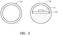
- FIG. 5shows an example of a flow channel according to the principles of the disclosure.
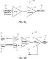
- FIGS. 6A & 6Bshow an example of signal amplification and filtering through a single amplifier or multiple amplifiers.
- FIG. 7is an electrical diagram of an eCig comprising a first and second thermopile.
- FIG. 8is an electrical diagram of an eCig comprising one thermopile.
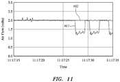
- FIGS. 9-11are graphs of an embodiment of the output of a reference signal and an airflow sensor according to the disclosure.
- FIG. 12is a flowchart illustrating one embodiment of a process for interpreting signals according to the disclosure.
- FIG. 1shows an example of an eCig 10 that is constructed according to an aspect of the disclosure.
- the eCig 10comprise a cartridge 14 and an eCig body 18 .
- the cartridge 14comprises an opening 12 through which aerosol may be delivered to a user.
- the cartridge 14comprises a flavorant (not shown) and an atomizer (not shown).
- the flavorantmay include, e.g., a liquid solution, a gel, a solid, or a gas that comprises molecules to be delivered in an aerosol to a user.
- the eCig body 18includes a power supply (e.g., a rechargeable Li-ion battery) (not shown) and an LED (not shown).
- the eCig 10includes a flow sensor device (not shown), which may include a microcontroller 20 (shown in FIG. 2 ) and a flow sensor 30 (shown in FIG. 3 ).
- FIG. 2shows an example of the microcontroller 20 constructed according to an aspect of the disclosure.
- the microcontroller 20comprises a microcomputer 26 , a memory 24 and an interface 28 .
- the microcontroller 20may include a driver 22 that drives an atomizer (not shown).
- the driver 22may include, e.g., a pulse-width modulator (PWM) or signal generator.
- PWMpulse-width modulator
- the microcomputer 20is configured to execute a computer program, which may be stored externally or in the memory 24 , to control operations of the eCig (e.g., eCig 10 , shown in FIG. 1 ), including activation (and deactivation) of the heating element.
- eCige.g., eCig 10 , shown in FIG. 1
- the memory 24includes a computer-readable medium that may store one or more segments or sections of computer code to carry out the processes described in the instant disclosure. Alternatively (or additionally) code segments or code sections may be provide on an external computer-readable medium (not shown) that may be accessed through the interface 28 .
- microcontroller 20may include an application specific integrated circuit (IC), or the like, in lieu of the microcomputer 26 , driver 22 , memory 22 , and/or interface 28 .
- ICapplication specific integrated circuit
- the microcontrollermay be configured to log medium flow data, including mass flow, volume flow, velocity data, time data, date data, flow duration data, and the like, that are associated with the medium flow.
- the mediummay comprise an aerosol, a gas (e.g., air), a liquid, or the like.
- the microcontrollermay be configured not only to turn ON/OFF a heater based on such data, but to also adjust control parameters such as heater PWM or amount of liquid solution dispensed onto a heating surface. This control may be done proportionally to the flow data or according to an algorithm where flow data is a parameter.
- the microcontrollermay use flow data to determine flow direction and restrict or limit false activation of the heater in case the user accidentally blows into the eCig 10 .
- FIG. 3shows an example of a flow sensor 30 that is constructed according to an aspect of the disclosure.
- the flow sensor 30comprises a substrate 31 and a thermopile (e.g., two or more thermocouples), including an upstream thermopile (or thermocouple) 32 and a downstream thermopile (or thermocouple) 33 .
- the substrate 31may include a thermal isolation base.
- the flow sensor 30may comprise a heater element 34 .
- the flow sensor 30may comprise a reference element 35 .
- the heater element 34may include a heater resistor.
- the reference element 35may include a reference resistor.
- thermopiles 32 , 33may be symmetrically positioned upstream and downstream from the heater element 34 .
- the heater element 34heats up the hot junctions of the thermopiles 32 , 33 .
- each of the thermopiles 32 , 33generates an output voltage that is proportional to the temperature gradient between its hot and cold junctions (the “Seebeck” effect).
- the hot junctions of the thermopiles 32 , 33 and the heater element 34may reside on the thermal isolation base.
- Mass air flow sensor signal conditioningmay be composed of various forms of filters or gain amplifiers. Filters may be used to eliminate noise before or after signal amplification, thereby reducing sensitivity to unwanted environmental noises or pressure changes.
- Filteringcan be accomplished using low pass, high pass, band pass, or a combination thereof.
- Signal gain amplificationmay be accomplished by employing electronic amplification on the upstream or downstream thermopile signals, or a combination thereof.
- Amplification of upstream or downstream thermopile signalsmay use a single state or multiple cascaded stages for each signal, or combination of these signals to form a sum or difference.
- the amplifier circuitmay include means to introducing a signal offset.
- the amplifiermay include transistors, operational amplifiers, or other integrated circuits.
- FIGS. 4A and 4Bshow examples of temperature profiles 41 , 42 as a function of airflow movement
- the temperature profile 41 upstream and downstream from the heating element 34is substantially symmetric (shown in FIG. 4A ).
- the temperature profile 42skews in the flow direction due to heat transport of the flowing medium, causing changes in the outputs of the thermopiles 32 , 33 .
- Heat transportis proportional to mass flow and heat capacity of the medium. Therefore, the flow sensor 30 measures the mass flow of the medium.
- the reference element 35may be placed next to the cold junction of the upstream thermopile 32 to provide data for temperature compensation.
- the microcontroller 20 and flow sensor 30may be provided in the cartridge 14 or the body 18 of the eCig 10 .
- the eCig 10may include multiple microcontrollers 20 and/or flow sensors 30 .
- the flow sensor 30may be positioned in a medium flow channel in the eCig 10 , so as to detect and measure medium flow (e.g., air flow, aerosol flow, liquid flow, or the like) when a user puffs (or draws) on the mouthpiece of the eCig 10 .
- medium flowe.g., air flow, aerosol flow, liquid flow, or the like
- a flow sensor 30may be placed near the air inlet, near the aerosol outlet, in an air channel, or the like, in the eCig 10 .
- the microcontroller 20may perform an adaptive algorithm that senses medium flow in the region of the flow sensor 30 by, e.g., driving and heating the heating element 34 in short bursts, using infrequent intervals and receiving the sensor signals from the thermopiles 32 , 33 , and, then, when a puff is detected (e.g., medium flowing above a predetermined threshold), switching to a more frequent cycle of driving the heating element 34 and receiving the sensor signals from the thermopiles 32 , 33 .
- an infrequent cyclemay comprise a 10 ms pulse every second and a frequent cycle may comprise a 10 ms pulse every 50 ms.
- the eCig 10may include an ON/OFF sensor, such as, for example: a capacitive sensor (not shown) that detects when a user contacts the cartridge 14 (e.g., user's finger or lips) and/or body 18 (e.g., user's fingers); a temperature sensor (not shown) that detects user contact (e.g. finger or lips) of the cartridge 14 and/or body 18 ; a pressure sensor (not shown) that detects a force applied to cartridge 14 and/or body 18 (e.g., squeeze by fingers or lips); an inertia sensor (not shown) that senses movement of the eCig 10 ; and the like.
- a capacitive sensornot shown
- a temperature sensorthat detects user contact (e.g. finger or lips) of the cartridge 14 and/or body 18
- a pressure sensornot shown
- an inertia sensornot shown that senses movement of the eCig 10 ; and the like.
- the microcontroller 20may be awoken (e.g., from a sleep mode) to drive the flow sensor 20 at a higher frequency cycle (e.g., a 50 ms cycle) so as to minimize any delay between user draw on the eCig 10 and delivery of the aerosol.
- a higher frequency cyclee.g., a 50 ms cycle
- the microcontroller 20may be set to a sleep mode to save battery life. In the sleep mode, the flow sensor may 20 may be driven at a low frequency cycle (e.g., a 1 sec cycle).
- the flow sensor 30is suitable for measurement of liquid flow, gas flow, and differential pressure applications.
- the flow sensor 30is sensitive at very low flow rates and pressure levels and does not have significant offset or offset drift due to its differential nature.
- the flow sensor 30provides for fast response and is resistant to vibration and pressure shock.
- the sensor 30is resistant to corrosive gases/liquids and abrasive wear.
- the flow sensor 30allows for implementation of simplified signal conditioning circuits ( FIGS. 6A & 6B ) in, e.g., the eCig 10 (shown in FIG. 1 ).
- the thermopiles and heatermay be used to determine temperature. For example, when there is no air flow, the heater may be turned ON in order to generate a known signal. The thermopiles would respond to the known heater input. This response would be impacted by the ambient temperature and may be determined. In this regard, rather than looking at a differential signal, one would look at the signal from only one of the thermopiles.
- FIG. 5shows an example of a flow channel according to the principles of the disclosure.
- the flow channelmay be shaped in the vicinity of the sensor so as to direct a majority of flow over the sensing surface, thus increasing the sensitivity of the system.
- the housing 120 of a normal cross-sectionis mostly open. In the cross-section near a sensor 131 , a housing 130 is restricted such that a pcb 132 and the sensor 131 are positioned so that a majority of the flow moves over the sensor 131 .
- a thermistor or other temperature measuring sensorcould be placed in the airflow.
- the signal from this sensorcould be used alone or in conjunction with a MAF in order to adjust the heater control signal or disable the eCig in response to temperature limits.
- a reference resistorcan be used to determine ambient environment and either adjust the heater via PWM or disable the heater when storage/operation temperature limits are exceeded.
- the mass airflow sensormay place an electrical current demand on the battery, it may be desirable to include a secondary means by which to initiate the operation of the mass airflow sensor.
- a secondary means by which to initiate the operation of the mass airflow sensoris possible in the rechargeable configuration of the eCig, a configuration where the liquid and heater are housed in a separate and detachable housing from the sensor and the battery.
- the microcontrollerwhich may also be housed with the sensor.
- the heaterwhich electronically behaves as a resistor, may complete a circuit that triggers an interrupt signal to be caused on an input pin of the microcontroller.
- This interrupt eventcould then cause the microcontroller to activate the previously inactive mass airflow sensor and begin to take readings using the mass airflow sensor.
- the microcontrollermay then deactivate the mass airflow sensor.
- the initiation of the mass airflow sensorcould be accomplished by using the heater resistance to complete a circuit, however, this is not the only means to accomplish such a trigger event.
- Other ways of accomplishing such a trigger eventinclude incorporating a dedicated physical connection or trace that completes a circuit, a capacitor that discharges or charges when the connection is made, and an integrated circuit that establishes communication with the microcontroller when the connection is made.
- FIGS. 6A and 6Billustrate an example of a single amplifier with a filter 164 and a difference amplifier and filters for upstream and downstream, with offset 180 .
- the airflow signal 160passes through a filter 161 and a gain amplifier 162 before a signal output 163 is transmitted.
- the difference amplifier and filters for upstream and downstream, with offset 180 shown in FIG. 6Bcomprises an upstream airflow signal 170 and a downstream airflow signal 171 .
- the upstream airflow signal 170passes through a first filter 172 and the downstream airflow signal passes through a second filter 173 .
- the outputs of the first and second filters 171 , 172then enter a difference amplifier 174 .
- a signalis then output from the difference amplifier 174 and enters a gain amplifier 175 along with an offset 175 .
- the gain amplifier 175then outputs a signal output 177 .
- FIG. 7illustrates an electrical diagram of an embodiment of the disclosure comprising a first thermopile 252 and a second thermopile 253 .
- the eCig depicted in FIG. 7comprises a microcontroller 240 , a mass airflow sensor 250 , an amplifier 249 , and a heater 256 .
- the mass airflow sensor 250comprises a mass airflow heater 251 , a first thermopile 252 , and a second thermopile 253 .
- the electrical diagramfurther illustrates the direction of airflow 254 over the mass airflow heater 251 and the first and second thermopiles 252 , 253 .
- the microcontroller 240can comprise a data acquisition circuit 241 , and an analog-to-digital converter 242 .
- the data acquisition circuit 241can log and transmit data such as temperature of the heater 256 , the number of times the heater 256 has been activated in a certain time, the length of time the heater 256 had been activated, and other information.
- data acquisition and transmissioncan be found in commonly assigned U.S. Provisional Application No. 61/907,239 filed 21 Nov. 2013, the entire disclosure of which is hereby incorporated by reference as though fully set forth herein.
- the analog-to-digital converter 242can output information about the eCig to the microcontroller 240 , the data acquisition circuit 241 , and other devices and sensors that may be present on the microcontroller 240 or otherwise connected to the eCig.
- FIG. 8illustrates an electrical diagram of another embodiment of the disclosure comprising one thermopile 352 .
- the eCig depicted in FIG. 8comprises a microcontroller 340 , a mass airflow sensor 350 , an amplifier 349 , and a heater 356 .
- the mass airflow sensor 350comprises a mass airflow heater 351 and a thermopile 352 .
- the electrical diagramfurther illustrates the direction of airflow over the heater 354 and the thermopile 352 .
- the microcontroller 340can comprise a data acquisition circuit 341 , and an analog-to-digital converter 342 .
- the data acquisition circuit 341can log and transmit data such as temperature of the heater 356 , the number of times the heater 356 has been activated in a certain time, the length of time the heater 356 had been activated, and other information.
- the analog-to-digital converter 342can output information about the eCig to the microcontroller 340 , the data acquisition circuit 341 , and other devices and sensors that may be present on the microcontroller 340 or otherwise connected to the eCig.
- the eCigcan also comprise feedback and gain resistors 357 , 358 .
- FIGS. 9-11illustrate graphical representations of the outputs of the reference signal and the mass air-flow sensor as discussed throughout the disclosure.
- a reference signal 460is normalized to a baseline of 2.0 volts.
- the reference signal 460can be normalized to a different baseline.
- the reference signal 460is composed of a moving average of the airflow signal when no airflow is present. This can establish a no-flow baseline condition.
- the output of the mass air flow sensor in relation to the reference signal 461can then be conditioned to output a baseline of 2.0 volts.
- the reference signal 460will normalize that change to the baseline.
- the output of the mass air flow sensor in relation to the reference signal 461can allow for subtle changes to occur in the environment, such as temperature change or battery depletion, without the output of the mass air flow sensor in relation to the reference signal 461 to drift.
- the reference signal 460will stay at the previously normalized baseline and the output of the mass air flow sensor in relation to the reference signal 461 will change proportionally to the amount of fluid flowing over the sensor.
- the output of the mass air flow sensorcan then change proportionally to the volume or velocity of the fluid moving past the sensor.
- the output of sensorcan change, but at a rate below the predetermined threshold, and can cause the microcontroller to normalize the reference signal 460 and the output of the mass air flow sensor in relation to the reference signal 461 to the desired baseline.
- the stress to the mass airflow sensorcan be either electrical or mechanical in nature.
- the stress to the mass airflow sensorcan also occur because of a change in the ambient temperature of the fluid flowing over the mass air flow sensor.
- the microcontrollercan vary the power output to the atomizer or heater coil. By varying the power output, the microcontroller can better control the temperature of the atomizer or heater coil.
- the microcontrollercan use the data from the flow sensor to run the eCig heater at a constant temperature over varying rates of flow. This constant temperature can result in a better experience for a user, as the flavorant or juice within the cartomizer or eCig will be vaporized at a constant temperature.
- FIG. 12illustrates a flow-chart of the process by which the microcontroller or other component can interpret signals from the mass airflow sensor or other device.
- a microcontrollercan monitor a sensor signal sent from the mass airflow sensor.
- the microcontrollercan determine if the change in the sensor signal is below a programmed threshold 501 . If the change in the sensor signal over a length of time is below the programmed threshold the microcontroller or other component can alter a reference signal and a relation signal to a predetermined baseline 502 .
- the reference signalcan be set to a baseline reading of 2.0 volts.
- the microcontrollerthan continues to monitor the mass airflow sensor for a change in the sensor signal 500 . If the change in the sensor signal over time is above a programmed threshold 501 , then the microcontroller or other component reads the difference between the reference signal and the relation signal 503 . In step 504 , the microcontroller or other component can operate a device, sensor, or other component according to the difference between the reference signal and the relation signal. The process then goes back to step 500 and the microcontroller or other component continues to monitor the mass airflow sensor for a change in the sensor signal over time.
- the microcontrollercan determine an amount of air flow that is passing over the mass airflow sensor by the difference between the reference signal and the relation signal. In another embodiment, the microcontroller can determine an amount of air flow that is passing through the body by the difference between the reference signal and the relation signal. Once the microcontroller determines or estimates an amount of air flow that is passing over the mass airflow sensor or through the body, the microcontroller can then vary the output of energy that is sent to the atomizer or heater. The microcontroller can vary the output of energy to keep the temperature of the atomizer or heater at a constant temperature or to otherwise control an aspect of the atomizer or heater.
- HVACheating ventilation and air conditioning
- automotivee.g., automotive, medical respirators, medical ventilators, diesel generators and engines (e.g., to monitor fuel consumption), drug delivery, biomedical analytical tools, and the like.
- HVACheating ventilation and air conditioning
- automotivee.g., automotive, medical respirators, medical ventilators, diesel generators and engines (e.g., to monitor fuel consumption), drug delivery, biomedical analytical tools, and the like.
- a “computer” or “microcomputer,” as used in this disclosure,means any machine, device, circuit, component, or module, or any system of machines, devices, circuits, components, modules, or the like, which are capable of manipulating data according to one or more instructions, such as, for example, without limitation, a processor, a microprocessor, a central processing unit, a general purpose computer, or the like, or an array of processors, microprocessors, central processing units, general purpose computers, or the like.
- a “computer-readable medium,” as used in this disclosure,means any medium that participates in providing data (for example, instructions) which may be read by a computer. Such a medium may take many forms, including non-volatile media, volatile media, and transmission media. Non-volatile media may include, for example, optical or magnetic disks and other persistent memory. Volatile media may include dynamic random access memory (DRAM). Transmission media may include coaxial cables, copper wire and fiber optics, including the wires that comprise a system bus coupled to the processor. Transmission media may include or convey acoustic waves, light waves and electromagnetic emissions, such as those generated during radio frequency (RF) and infrared (IR) data communications.
- RFradio frequency
- IRinfrared
- Computer-readable mediainclude, for example, a flexible disk, hard disk, magnetic tape, any other magnetic medium, any other optical medium, a RAM, a PROM, an EPROM, a FLASH-EEPROM, any other memory chip or cartridge, a carrier wave as described hereinafter, or any other medium from which a computer can read.
- sequences of instructionmay be delivered from a RAM to a processor, (ii) may be carried over a wireless transmission medium, and/or (iii) may be formatted according to numerous formats, standards or protocols known in the art as of the date of this writing.
- Devices that are in communication with each otherneed not be in continuous communication with each other, unless expressly specified otherwise.
- devices that are in communication with each othermay communicate directly or indirectly through one or more intermediaries.
Landscapes
- Health & Medical Sciences (AREA)
- Engineering & Computer Science (AREA)
- Hematology (AREA)
- Life Sciences & Earth Sciences (AREA)
- Veterinary Medicine (AREA)
- Anesthesiology (AREA)
- Biomedical Technology (AREA)
- Heart & Thoracic Surgery (AREA)
- Public Health (AREA)
- General Health & Medical Sciences (AREA)
- Animal Behavior & Ethology (AREA)
- General Physics & Mathematics (AREA)
- Physics & Mathematics (AREA)
- Fluid Mechanics (AREA)
- Bioinformatics & Cheminformatics (AREA)
- Pulmonology (AREA)
- Measuring Volume Flow (AREA)
- Radiation Pyrometers (AREA)
Abstract
Description
Claims (17)
Priority Applications (1)
| Application Number | Priority Date | Filing Date | Title |
|---|---|---|---|
| US14/899,103US10905162B2 (en) | 2013-06-19 | 2014-06-19 | Device and method for sensing mass airflow |
Applications Claiming Priority (3)
| Application Number | Priority Date | Filing Date | Title |
|---|---|---|---|
| US201361836923P | 2013-06-19 | 2013-06-19 | |
| PCT/US2014/043253WO2014205263A1 (en) | 2013-06-19 | 2014-06-19 | Device and method for sensing mass airflow |
| US14/899,103US10905162B2 (en) | 2013-06-19 | 2014-06-19 | Device and method for sensing mass airflow |
Publications (2)
| Publication Number | Publication Date |
|---|---|
| US20160366939A1 US20160366939A1 (en) | 2016-12-22 |
| US10905162B2true US10905162B2 (en) | 2021-02-02 |
Family
ID=52105307
Family Applications (1)
| Application Number | Title | Priority Date | Filing Date |
|---|---|---|---|
| US14/899,103Active2035-08-14US10905162B2 (en) | 2013-06-19 | 2014-06-19 | Device and method for sensing mass airflow |
Country Status (12)
| Country | Link |
|---|---|
| US (1) | US10905162B2 (en) |
| EP (1) | EP3011405B1 (en) |
| JP (3) | JP2016525345A (en) |
| KR (1) | KR102321843B1 (en) |
| CN (1) | CN105452977B (en) |
| AU (1) | AU2014281351B2 (en) |
| BR (1) | BR112015032001B1 (en) |
| CA (1) | CA2916242C (en) |
| MX (2) | MX356938B (en) |
| RU (2) | RU2763434C2 (en) |
| WO (1) | WO2014205263A1 (en) |
| ZA (1) | ZA201600046B (en) |
Cited By (3)
| Publication number | Priority date | Publication date | Assignee | Title |
|---|---|---|---|---|
| US12213535B2 (en) | 2013-11-12 | 2025-02-04 | Vmr Products Llc | Vaporizer |
| US12226567B2 (en) | 2016-09-22 | 2025-02-18 | Pax Labs, Inc. | Leak-resistant vaporizer device |
| US12279646B2 (en) | 2014-02-06 | 2025-04-22 | Juul Labs, Inc. | Cartridge of vaporization device systems having unequal transverse cartridge dimensions |
Families Citing this family (91)
| Publication number | Priority date | Publication date | Assignee | Title |
|---|---|---|---|---|
| US20160345631A1 (en) | 2005-07-19 | 2016-12-01 | James Monsees | Portable devices for generating an inhalable vapor |
| US10517530B2 (en) | 2012-08-28 | 2019-12-31 | Juul Labs, Inc. | Methods and devices for delivering and monitoring of tobacco, nicotine, or other substances |
| US10279934B2 (en) | 2013-03-15 | 2019-05-07 | Juul Labs, Inc. | Fillable vaporizer cartridge and method of filling |
| CN105263345A (en) | 2013-05-06 | 2016-01-20 | 派克斯实验公司 | Nicotine salt formulations for aerosol devices and methods thereof |
| CN105473012B (en) | 2013-06-14 | 2020-06-19 | 尤尔实验室有限公司 | Multiple heating elements with separate vaporizable materials in electronic vaporization equipment |
| CN106102811B (en)* | 2013-11-21 | 2020-03-10 | 方特慕控股第四私人有限公司 | Apparatus, method and system for recording smoking data |
| KR20240070710A (en) | 2013-12-05 | 2024-05-21 | 쥴 랩스, 인크. | Nicotine liquid formulations for aerosol devices and methods thereof |
| DE202014011260U1 (en) | 2013-12-23 | 2018-11-13 | Juul Labs Uk Holdco Limited | Systems for an evaporation device |
| US10076139B2 (en) | 2013-12-23 | 2018-09-18 | Juul Labs, Inc. | Vaporizer apparatus |
| US10159282B2 (en) | 2013-12-23 | 2018-12-25 | Juul Labs, Inc. | Cartridge for use with a vaporizer device |
| US10058129B2 (en) | 2013-12-23 | 2018-08-28 | Juul Labs, Inc. | Vaporization device systems and methods |
| USD825102S1 (en) | 2016-07-28 | 2018-08-07 | Juul Labs, Inc. | Vaporizer device with cartridge |
| USD842536S1 (en) | 2016-07-28 | 2019-03-05 | Juul Labs, Inc. | Vaporizer cartridge |
| US20160366947A1 (en) | 2013-12-23 | 2016-12-22 | James Monsees | Vaporizer apparatus |
| TWI761216B (en) | 2014-02-06 | 2022-04-11 | 美商尤爾實驗室有限公司 | A device for generating an inhalable aerosol and a separable cartridge for use therewith |
| US10130119B2 (en) | 2014-02-28 | 2018-11-20 | Beyond Twenty Ltd. | Electronic vaporiser system |
| GB201413027D0 (en) | 2014-02-28 | 2014-09-03 | Beyond Twenty Ltd | Beyond 4 |
| US10472226B2 (en) | 2014-02-28 | 2019-11-12 | Ayr Ltd. | Electronic vaporiser system |
| US12295411B2 (en) | 2014-02-28 | 2025-05-13 | Ayr Ltd. | Electronic vaporizer system |
| US10588176B2 (en) | 2014-02-28 | 2020-03-10 | Ayr Ltd. | Electronic vaporiser system |
| US10091839B2 (en) | 2014-02-28 | 2018-10-02 | Beyond Twenty Ltd. | Electronic vaporiser system |
| US11085550B2 (en) | 2014-02-28 | 2021-08-10 | Ayr Ltd. | Electronic vaporiser system |
| US10136674B2 (en) | 2014-02-28 | 2018-11-27 | Beyond Twenty Ltd. | Electronic vaporiser system |
| WO2015175979A1 (en) | 2014-05-16 | 2015-11-19 | Pax Labs, Inc. | Systems and methods for aerosolizing a smokeable material |
| CA160775S (en) | 2014-08-11 | 2015-09-29 | Ploom Inc | Electronic vaporization device with cartridge |
| CN111449299B (en) | 2014-08-22 | 2024-02-13 | 富特姆投资有限公司 | Method, system and apparatus for controlling a heating element |
| MX394125B (en) | 2014-12-05 | 2025-03-24 | Juul Labs Inc | CALIBRATED DOSE CONTROL |
| EA034513B1 (en)* | 2015-02-27 | 2020-02-14 | Джапан Тобакко Инк. | Non-burning type flavor inhaler |
| CA2997119C (en)* | 2015-09-01 | 2023-10-24 | Beyond Twenty Limited | Electronic vaporiser system |
| CN105167203B (en)* | 2015-09-09 | 2016-12-07 | 深圳麦克韦尔股份有限公司 | Electronic cigarette and heating atomization control method thereof |
| CN105394817B (en)* | 2015-12-09 | 2018-06-29 | 卓尔悦欧洲控股有限公司 | A control device with reminder function, electronic cigarette and control method |
| US11291252B2 (en)* | 2015-12-18 | 2022-04-05 | Rai Strategic Holdings, Inc. | Proximity sensing for an aerosol delivery device |
| EP3413960B1 (en) | 2016-02-11 | 2021-03-31 | Juul Labs, Inc. | Fillable vaporizer cartridge and method of filling |
| CO2018009342A2 (en) | 2016-02-11 | 2018-09-20 | Juul Labs Inc | Secure fixing cartridges for vaporizing devices |
| EP4467952A3 (en) | 2016-02-11 | 2025-03-05 | Juul Labs, Inc. | Vaporizer devices with blow discrimination |
| EP3205244A1 (en)† | 2016-02-12 | 2017-08-16 | Qbo Coffee GmbH | Machine for making beverages |
| UA126061C2 (en) | 2016-02-25 | 2022-08-10 | Джуул Лебз, Інк. | SYSTEMS AND METHODS OF CONTROLLING THE EVAPORATION DEVICE |
| US10405582B2 (en) | 2016-03-10 | 2019-09-10 | Pax Labs, Inc. | Vaporization device with lip sensing |
| USD849996S1 (en) | 2016-06-16 | 2019-05-28 | Pax Labs, Inc. | Vaporizer cartridge |
| USD836541S1 (en) | 2016-06-23 | 2018-12-25 | Pax Labs, Inc. | Charging device |
| USD848057S1 (en) | 2016-06-23 | 2019-05-07 | Pax Labs, Inc. | Lid for a vaporizer |
| USD851830S1 (en) | 2016-06-23 | 2019-06-18 | Pax Labs, Inc. | Combined vaporizer tamp and pick tool |
| US10757973B2 (en) | 2016-07-25 | 2020-09-01 | Fontem Holdings 1 B.V. | Electronic cigarette with mass air flow sensor |
| US11147315B2 (en) | 2016-07-25 | 2021-10-19 | Fontem Holdings 1 B.V. | Controlling an operation of an electronic cigarette |
| CN107649327A (en)* | 2016-07-26 | 2018-02-02 | 上海新微技术研发中心有限公司 | Atomizing device and atomizing method |
| US10837813B2 (en) | 2016-08-25 | 2020-11-17 | The Trustees Of Princeton University | Nanowires integration for real-time compensation |
| CA173126S (en)* | 2016-09-30 | 2019-02-14 | Fontem Holdings 1 Bv | Electronic vaping device |
| EP3547861B1 (en) | 2016-12-02 | 2021-01-20 | VMR Products LLC | Combination vaporizer |
| CN106579567A (en)* | 2017-01-17 | 2017-04-26 | 深圳市合元科技有限公司 | Atomizer and control method therefor |
| US10080388B2 (en)* | 2017-01-25 | 2018-09-25 | Rai Strategic Holdings, Inc. | Aerosol delivery device including a shape-memory alloy and a related method |
| CN108338414B (en)* | 2017-01-25 | 2022-05-27 | 贵州中烟工业有限责任公司 | Control method and control system for electric heating smoking system |
| USD887632S1 (en) | 2017-09-14 | 2020-06-16 | Pax Labs, Inc. | Vaporizer cartridge |
| US11039645B2 (en)* | 2017-09-19 | 2021-06-22 | Rai Strategic Holdings, Inc. | Differential pressure sensor for an aerosol delivery device |
| EP3691482B1 (en)* | 2017-10-05 | 2022-02-09 | Philip Morris Products S.A. | Electrically operated aerosol-generating device with continuous power regulation |
| ES2875352T3 (en)* | 2017-11-20 | 2021-11-10 | Presspart Gmbh & Co Kg | Inhalation system |
| IL263217B (en) | 2017-11-24 | 2022-06-01 | Juul Labs Inc | Emission sensing and power circuit for vaporizers |
| US11035704B2 (en) | 2017-12-29 | 2021-06-15 | Altria Client Services Llc | Sensor apparatus |
| US11592838B2 (en) | 2018-02-28 | 2023-02-28 | Instrumems Inc. | Velocity sensing for aircraft |
| CN108308720B (en)* | 2018-04-12 | 2025-03-18 | 深圳市新宜康科技股份有限公司 | Atomization device and control method thereof using thermal field temperature difference control |
| GB201806826D0 (en)* | 2018-04-26 | 2018-06-13 | Nicoventures Trading Ltd | Electronic aerosol provision system and method |
| EP3574779A3 (en)* | 2018-05-28 | 2020-03-04 | Hauni Maschinenbau GmbH | Arrangement for an inhaler |
| DE102018127927A1 (en)* | 2018-05-28 | 2019-11-28 | Hauni Maschinenbau Gmbh | Arrangement and base part for an inhaler, and inhaler |
| US10986875B2 (en) | 2018-06-25 | 2021-04-27 | Juul Labs, Inc. | Vaporizer device heater control |
| CN108851242B (en)* | 2018-07-18 | 2021-02-19 | 东莞市麦斯莫科电子科技有限公司 | Heating element temperature control method and device and electronic smoking system |
| CN109283867A (en)* | 2018-08-24 | 2019-01-29 | 深圳市合元科技有限公司 | A switch control circuit, switch control method and electronic cigarette |
| US11413409B2 (en) | 2018-09-12 | 2022-08-16 | Juul Labs, Inc. | Vaporizer including positive temperature coefficient of resistivity (PTCR) heating element |
| US11517051B2 (en)* | 2018-09-19 | 2022-12-06 | Fontem Ventures B.V. | Electronic smoking device with self-heating compensation |
| JP6577113B1 (en)* | 2018-10-03 | 2019-09-18 | 日本たばこ産業株式会社 | Aerosol generating device, control unit, method and program for aerosol generating device |
| JP2020058236A (en) | 2018-10-04 | 2020-04-16 | 日本たばこ産業株式会社 | Suction component generation device, control circuit, control method and control program for suction component generation device |
| JP6557391B1 (en)* | 2018-10-11 | 2019-08-07 | 日本たばこ産業株式会社 | Suction component generation device, control circuit, control method and control program for suction component generation device |
| WO2020084761A1 (en)* | 2018-10-26 | 2020-04-30 | 日本たばこ産業株式会社 | Suction device |
| WO2020090374A1 (en) | 2018-10-30 | 2020-05-07 | 日本たばこ産業株式会社 | Power supply unit of aerosol generation device, control method of power supply unit of aerosol generation device, and program for power supply unit of aerosol generation device |
| GB201818007D0 (en) | 2018-11-05 | 2018-12-19 | Nicoventures Trading Ltd | Device calibration and method |
| PL3958696T3 (en)* | 2019-04-23 | 2024-05-13 | Philip Morris Products S.A. | Aerosol generating device with puff detection and puff detection method |
| JP2022120206A (en)* | 2019-04-24 | 2022-08-18 | 株式会社村田製作所 | Non-combustion type aspirator |
| CN111838755B (en)* | 2019-04-25 | 2025-07-11 | 常州市派腾电子技术服务有限公司 | Electronic cigarette and control method thereof |
| US20200338282A1 (en)* | 2019-04-27 | 2020-10-29 | Michael Trzecieski | Vaporizer cartridge system for identifying a cartridge inserted into a battery unit |
| CN113993399A (en)* | 2019-06-21 | 2022-01-28 | 日本烟草国际股份有限公司 | Mass flow meter for electronic cigarette |
| CN110279155B (en) | 2019-06-27 | 2025-05-13 | 深圳雾芯科技有限公司 | Electronic atomizer device, electronic atomizer device body and operation method |
| WO2021011739A1 (en)* | 2019-07-17 | 2021-01-21 | Instrumems Inc. | Vaporizer flow detection |
| CN112438438A (en)* | 2019-08-28 | 2021-03-05 | 常州市派腾电子技术服务有限公司 | Power supply device, aerosol generating device and control method thereof |
| CN110506997A (en)* | 2019-09-03 | 2019-11-29 | 上海矽睿科技有限公司 | A kind of electronic cigarette and its control method |
| GB201917489D0 (en)* | 2019-11-29 | 2020-01-15 | Nicoventures Trading Ltd | Vapour provision systems |
| CN112326101A (en)* | 2020-11-20 | 2021-02-05 | 深圳市康泓威科技有限公司 | Electronic atomization device with digital air pressure sensing chip and control method thereof |
| CN112716060B (en)* | 2021-01-26 | 2024-01-05 | 深圳市海派特光伏科技有限公司 | Electronic cigarette heating control circuit and method, integrated circuit and electronic cigarette |
| EP4340164A4 (en) | 2021-05-10 | 2025-05-14 | Japan Tobacco Inc. | Power supply unit of aerosol generation device |
| JP7467770B2 (en) | 2021-05-10 | 2024-04-15 | 日本たばこ産業株式会社 | Aerosol generator power supply unit |
| WO2023037445A1 (en)* | 2021-09-08 | 2023-03-16 | 日本たばこ産業株式会社 | Inhalation device, substrate, and control method |
| CN118369003A (en) | 2021-12-10 | 2024-07-19 | 日本烟草产业株式会社 | Power supply unit for aerosol-generating device |
| CN115435855B (en)* | 2022-08-25 | 2024-11-01 | 上海声动微科技有限公司 | Flow sensor and preparation method thereof |
| WO2025004180A1 (en)* | 2023-06-27 | 2025-01-02 | 日本たばこ産業株式会社 | Aerosol generation system, information processing method, and program |
Citations (27)
| Publication number | Priority date | Publication date | Assignee | Title |
|---|---|---|---|---|
| US3548841A (en)* | 1967-10-30 | 1970-12-22 | Gallaher Ltd | Cigarette smoking machines |
| US4660510A (en)* | 1984-07-31 | 1987-04-28 | Westinghouse Electric Corp. | Model steam generator having a thermosyphon heating means |
| JPS63122963A (en) | 1986-11-04 | 1988-05-26 | フアオ・デ−・オ−・ア−ドルフ・シントリング・アクチエンゲゼルシヤフト | Fluid-direction measuring device |
| US4947875A (en)* | 1988-09-08 | 1990-08-14 | R. J. Reynolds Tobacco Company | Flavor delivery articles utilizing electrical energy |
| US5967148A (en)* | 1997-10-16 | 1999-10-19 | Philip Morris Incorporated | Lighter actuation system |
| US6040560A (en)* | 1996-10-22 | 2000-03-21 | Philip Morris Incorporated | Power controller and method of operating an electrical smoking system |
| JP2004516101A (en) | 2000-12-22 | 2004-06-03 | クリサリス テクノロジーズ インコーポレイテッド | Aerosol generator with multiple heating zones and method of use |
| JP2004212103A (en) | 2002-12-27 | 2004-07-29 | Yamatake Corp | Thermal flow meter and smoking device |
| CN1541577A (en) | 2003-04-29 | 2004-11-03 | Non-combustible electronic spray cigarette | |
| JP2005038058A (en) | 2003-07-16 | 2005-02-10 | Tokyo Electron Ltd | Equipment and method for manufacturing semiconductor |
| US7034677B2 (en)* | 2002-07-19 | 2006-04-25 | Smiths Detection Inc. | Non-specific sensor array detectors |
| US20070144514A1 (en)* | 2005-12-22 | 2007-06-28 | Yeates Donovan B | Aerosol processing and inhalation method and system for high dose rate aerosol drug delivery |
| US20090090361A1 (en)* | 2007-10-09 | 2009-04-09 | Anand Gumaste | Inhalation device |
| WO2010003480A1 (en) | 2008-07-08 | 2010-01-14 | Philip Morris Products S.A. | A flow sensor system |
| US20100163063A1 (en)* | 2008-12-24 | 2010-07-01 | Philip Morris Usa Inc. | Article Including Identification Information for Use in an Electrically Heated Smoking System |
| GB2468932A (en) | 2009-03-24 | 2010-09-29 | Beijing Green World Technologies Ltd | Electronic cigarette |
| US20100307518A1 (en)* | 2007-05-11 | 2010-12-09 | Smokefree Innotec Corporation | Smoking device, charging means and method of using it |
| US20110031419A1 (en)* | 2008-04-24 | 2011-02-10 | Panasonic Electric Works Co., Ltd. | Smoke sensor |
| US20110226236A1 (en) | 2008-10-23 | 2011-09-22 | Helmut Buchberger | Inhaler |
| CN102227175A (en) | 2009-09-18 | 2011-10-26 | 微创高科有限公司 | e-cigarette |
| US20110265806A1 (en)* | 2010-04-30 | 2011-11-03 | Ramon Alarcon | Electronic smoking device |
| WO2011160788A1 (en) | 2010-06-23 | 2011-12-29 | Philip Morris Products S.A. | An improved aerosol generator and liquid storage portion for use with the aerosol generator |
| US20120048266A1 (en)* | 2010-08-24 | 2012-03-01 | Eli Alelov | Inhalation device including substance usage controls |
| US20120050750A1 (en)* | 2009-04-21 | 2012-03-01 | Michigan Aerospace Corporation | Atmospheric measurement system |
| CN202172847U (en) | 2011-07-26 | 2012-03-28 | 比尔丹尼·马朗戈斯 | Electronic cigarette |
| US20120199146A1 (en)* | 2011-02-09 | 2012-08-09 | Bill Marangos | Electronic cigarette |
| WO2013060781A1 (en) | 2011-10-27 | 2013-05-02 | Philip Morris Products S.A. | Aerosol generating system with improved aerosol production |
Family Cites Families (5)
| Publication number | Priority date | Publication date | Assignee | Title |
|---|---|---|---|---|
| US7082825B2 (en)* | 2002-12-27 | 2006-08-01 | Yamatake Corporation | Smoking device including a flowmeter |
| CA2554005C (en)* | 2004-02-24 | 2013-05-28 | Microdose Technologies, Inc. | Directional flow sensor inhaler |
| JP5279898B2 (en)* | 2008-05-23 | 2013-09-04 | エーティーラブ・インコーポレーテッド | Contact sensor device and operation mode switching method of the device |
| KR102177660B1 (en)* | 2011-08-16 | 2020-11-12 | 쥴 랩스, 인크. | Low temperature electronic vaporization device and methods |
| RU115629U1 (en)* | 2011-10-10 | 2012-05-10 | Сергей Павлович Кузьмин | ELECTRONIC CIGARETTE |
- 2014
- 2014-06-19CACA2916242Apatent/CA2916242C/enactiveActive
- 2014-06-19WOPCT/US2014/043253patent/WO2014205263A1/enactiveApplication Filing
- 2014-06-19CNCN201480035481.8Apatent/CN105452977B/enactiveActive
- 2014-06-19MXMX2015017962Apatent/MX356938B/enactiveIP Right Grant
- 2014-06-19AUAU2014281351Apatent/AU2014281351B2/enactiveActive
- 2014-06-19BRBR112015032001-5Apatent/BR112015032001B1/enactiveIP Right Grant
- 2014-06-19MXMX2018007545Apatent/MX373005B/enunknown
- 2014-06-19EPEP14813245.9Apatent/EP3011405B1/enactiveActive
- 2014-06-19RURU2018118600Apatent/RU2763434C2/enactive
- 2014-06-19JPJP2016521819Apatent/JP2016525345A/enactivePending
- 2014-06-19KRKR1020167001524Apatent/KR102321843B1/enactiveActive
- 2014-06-19USUS14/899,103patent/US10905162B2/enactiveActive
- 2014-06-19RURU2016101273Apatent/RU2655908C2/enactive
- 2016
- 2016-01-04ZAZA2016/00046Apatent/ZA201600046B/enunknown
- 2019
- 2019-01-17JPJP2019006388Apatent/JP2019071897A/enactivePending
- 2021
- 2021-03-30JPJP2021057663Apatent/JP7181335B2/enactiveActive
Patent Citations (34)
| Publication number | Priority date | Publication date | Assignee | Title |
|---|---|---|---|---|
| US3548841A (en)* | 1967-10-30 | 1970-12-22 | Gallaher Ltd | Cigarette smoking machines |
| US4660510A (en)* | 1984-07-31 | 1987-04-28 | Westinghouse Electric Corp. | Model steam generator having a thermosyphon heating means |
| JPS63122963A (en) | 1986-11-04 | 1988-05-26 | フアオ・デ−・オ−・ア−ドルフ・シントリング・アクチエンゲゼルシヤフト | Fluid-direction measuring device |
| US4947875A (en)* | 1988-09-08 | 1990-08-14 | R. J. Reynolds Tobacco Company | Flavor delivery articles utilizing electrical energy |
| US6040560A (en)* | 1996-10-22 | 2000-03-21 | Philip Morris Incorporated | Power controller and method of operating an electrical smoking system |
| US5967148A (en)* | 1997-10-16 | 1999-10-19 | Philip Morris Incorporated | Lighter actuation system |
| JP2004516101A (en) | 2000-12-22 | 2004-06-03 | クリサリス テクノロジーズ インコーポレイテッド | Aerosol generator with multiple heating zones and method of use |
| US7034677B2 (en)* | 2002-07-19 | 2006-04-25 | Smiths Detection Inc. | Non-specific sensor array detectors |
| JP2004212103A (en) | 2002-12-27 | 2004-07-29 | Yamatake Corp | Thermal flow meter and smoking device |
| CN1541577A (en) | 2003-04-29 | 2004-11-03 | Non-combustible electronic spray cigarette | |
| EP1618803A1 (en) | 2003-04-29 | 2006-01-25 | Lik Hon | A flameless electronic atomizing cigarette |
| US20060196518A1 (en)* | 2003-04-29 | 2006-09-07 | Lik Hon | Flameless electronic atomizing cigarette |
| JP2005038058A (en) | 2003-07-16 | 2005-02-10 | Tokyo Electron Ltd | Equipment and method for manufacturing semiconductor |
| US20060172442A1 (en) | 2003-07-16 | 2006-08-03 | Tsuneyuki Okabe | Semiconductor production system and semiconductor production process |
| US20070144514A1 (en)* | 2005-12-22 | 2007-06-28 | Yeates Donovan B | Aerosol processing and inhalation method and system for high dose rate aerosol drug delivery |
| US20100307518A1 (en)* | 2007-05-11 | 2010-12-09 | Smokefree Innotec Corporation | Smoking device, charging means and method of using it |
| US20090090361A1 (en)* | 2007-10-09 | 2009-04-09 | Anand Gumaste | Inhalation device |
| US20110031419A1 (en)* | 2008-04-24 | 2011-02-10 | Panasonic Electric Works Co., Ltd. | Smoke sensor |
| WO2010003480A1 (en) | 2008-07-08 | 2010-01-14 | Philip Morris Products S.A. | A flow sensor system |
| JP2012506263A (en) | 2008-10-23 | 2012-03-15 | ブッフベルガー,ヘルムート | Inhaler |
| US20110226236A1 (en) | 2008-10-23 | 2011-09-22 | Helmut Buchberger | Inhaler |
| US20100163063A1 (en)* | 2008-12-24 | 2010-07-01 | Philip Morris Usa Inc. | Article Including Identification Information for Use in an Electrically Heated Smoking System |
| GB2468932A (en) | 2009-03-24 | 2010-09-29 | Beijing Green World Technologies Ltd | Electronic cigarette |
| US20100242974A1 (en)* | 2009-03-24 | 2010-09-30 | Guocheng Pan | Electronic Cigarette |
| US20120050750A1 (en)* | 2009-04-21 | 2012-03-01 | Michigan Aerospace Corporation | Atmospheric measurement system |
| US20120186594A1 (en)* | 2009-09-18 | 2012-07-26 | Minilogic Device Corporation Ltd. | Electronic smoke |
| CN102227175A (en) | 2009-09-18 | 2011-10-26 | 微创高科有限公司 | e-cigarette |
| US20110265806A1 (en)* | 2010-04-30 | 2011-11-03 | Ramon Alarcon | Electronic smoking device |
| CN102970885A (en) | 2010-04-30 | 2013-03-13 | 洛艾克有限公司 | Electronic smoking device |
| WO2011160788A1 (en) | 2010-06-23 | 2011-12-29 | Philip Morris Products S.A. | An improved aerosol generator and liquid storage portion for use with the aerosol generator |
| US20120048266A1 (en)* | 2010-08-24 | 2012-03-01 | Eli Alelov | Inhalation device including substance usage controls |
| US20120199146A1 (en)* | 2011-02-09 | 2012-08-09 | Bill Marangos | Electronic cigarette |
| CN202172847U (en) | 2011-07-26 | 2012-03-28 | 比尔丹尼·马朗戈斯 | Electronic cigarette |
| WO2013060781A1 (en) | 2011-10-27 | 2013-05-02 | Philip Morris Products S.A. | Aerosol generating system with improved aerosol production |
Cited By (4)
| Publication number | Priority date | Publication date | Assignee | Title |
|---|---|---|---|---|
| US12213535B2 (en) | 2013-11-12 | 2025-02-04 | Vmr Products Llc | Vaporizer |
| US12279646B2 (en) | 2014-02-06 | 2025-04-22 | Juul Labs, Inc. | Cartridge of vaporization device systems having unequal transverse cartridge dimensions |
| US12226567B2 (en) | 2016-09-22 | 2025-02-18 | Pax Labs, Inc. | Leak-resistant vaporizer device |
| US12311099B2 (en) | 2016-09-22 | 2025-05-27 | Pax Labs, Inc. | Leak-resistant vaporizer device |
Also Published As
| Publication number | Publication date |
|---|---|
| MX373005B (en) | 2020-06-22 |
| JP2021112188A (en) | 2021-08-05 |
| RU2763434C2 (en) | 2021-12-29 |
| RU2016101273A (en) | 2017-07-25 |
| KR102321843B1 (en) | 2021-11-08 |
| WO2014205263A1 (en) | 2014-12-24 |
| EP3011405B1 (en) | 2018-03-28 |
| KR20160033112A (en) | 2016-03-25 |
| ZA201600046B (en) | 2017-04-26 |
| EP3011405A1 (en) | 2016-04-27 |
| BR112015032001B1 (en) | 2022-04-26 |
| MX2015017962A (en) | 2016-10-28 |
| JP2016525345A (en) | 2016-08-25 |
| MX356938B (en) | 2018-06-20 |
| BR112015032001A2 (en) | 2017-07-25 |
| AU2014281351B2 (en) | 2020-03-12 |
| AU2014281351A1 (en) | 2016-01-28 |
| JP2019071897A (en) | 2019-05-16 |
| US20160366939A1 (en) | 2016-12-22 |
| CA2916242C (en) | 2022-02-22 |
| RU2018118600A3 (en) | 2021-10-22 |
| CN105452977B (en) | 2021-11-02 |
| CA2916242A1 (en) | 2014-12-24 |
| RU2018118600A (en) | 2018-11-08 |
| RU2655908C2 (en) | 2018-05-29 |
| EP3011405A4 (en) | 2017-03-01 |
| JP7181335B2 (en) | 2022-11-30 |
| CN105452977A (en) | 2016-03-30 |
Similar Documents
| Publication | Publication Date | Title |
|---|---|---|
| US10905162B2 (en) | Device and method for sensing mass airflow | |
| US10201186B2 (en) | Method, system and device for controlling a heating element | |
| US11051558B2 (en) | Unburned tobacco controller in true response to smoker's puff process | |
| US20170280779A1 (en) | Electronic cigarette temperature control system and method, and electronic cigarette with the same | |
| CN107228693B (en) | System and method for determining gas | |
| AU2025204147A1 (en) | Anemometric-assisted control of a vaporizer | |
| JP2021112188A5 (en) | ||
| WO2013098397A3 (en) | Aerosol generating device with air flow detection | |
| US20080009980A1 (en) | Method for controlling system to work at appropriate temperature | |
| US9163964B2 (en) | Device for detecting at least one flow characteristic of a fluid medium | |
| CN109007976A (en) | Electric heater unit with puff number tally function | |
| CN204191588U (en) | Temperature control electronic cigarette | |
| KR20230038725A (en) | Steady-State Resistance Estimation for Overheat Protection in Nicotine E-vaping Devices | |
| WO2004025286A1 (en) | Urea concentration identifying system, method for identifying urea concentration and automobile exhaust gas reducing system using same, and method for reducing automobile exhaust gas | |
| CN208523778U (en) | Electronic cigarette control system | |
| DE502004004371D1 (en) | Temperature sensor | |
| CN108308720B (en) | Atomization device and control method thereof using thermal field temperature difference control | |
| JP2009539069A (en) | Method and device for operating a MOX gas sensor | |
| CN101075152B (en) | Method for controlling computer system to work at proper temperature | |
| US20240277070A1 (en) | Aerosol generating device and operating method thereof | |
| JPH06194329A (en) | Gas detector | |
| CN115379599A (en) | An atomizer heating circuit and control method with controllable output power | |
| KR20250018088A (en) | Sensor with reduced power consumption and associated method | |
| EA050330B1 (en) | POWER SUPPLY FOR AEROSOL GENERATING DEVICE | |
| RU2023103121A (en) | EVAPORATORY DEVICE AND METHOD OF ITS OPERATION |
Legal Events
| Date | Code | Title | Description |
|---|---|---|---|
| AS | Assignment | Owner name:LOEC, INC., NORTH CAROLINA Free format text:ASSIGNMENT OF ASSIGNORS INTEREST;ASSIGNOR:ALARCON, RAMON;REEL/FRAME:038364/0577 Effective date:20160211 | |
| AS | Assignment | Owner name:LOEC, INC., NORTH CAROLINA Free format text:ASSIGNMENT OF ASSIGNORS INTEREST;ASSIGNOR:STARMAN, MICHAEL;REEL/FRAME:046098/0851 Effective date:20160211 Owner name:FONTEM HOLDINGS 4 B.V., NETHERLANDS Free format text:ASSIGNMENT OF ASSIGNORS INTEREST;ASSIGNOR:LOEC, INC.;REEL/FRAME:046098/0928 Effective date:20160718 | |
| STPP | Information on status: patent application and granting procedure in general | Free format text:DOCKETED NEW CASE - READY FOR EXAMINATION | |
| STPP | Information on status: patent application and granting procedure in general | Free format text:NON FINAL ACTION MAILED | |
| STPP | Information on status: patent application and granting procedure in general | Free format text:RESPONSE TO NON-FINAL OFFICE ACTION ENTERED AND FORWARDED TO EXAMINER | |
| STPP | Information on status: patent application and granting procedure in general | Free format text:FINAL REJECTION MAILED | |
| STPP | Information on status: patent application and granting procedure in general | Free format text:ADVISORY ACTION MAILED | |
| STPP | Information on status: patent application and granting procedure in general | Free format text:NON FINAL ACTION MAILED | |
| FEPP | Fee payment procedure | Free format text:PETITION RELATED TO MAINTENANCE FEES GRANTED (ORIGINAL EVENT CODE: PTGR); ENTITY STATUS OF PATENT OWNER: LARGE ENTITY | |
| STCF | Information on status: patent grant | Free format text:PATENTED CASE | |
| AS | Assignment | Owner name:FONTEM HOLDINGS B.V., NETHERLANDS Free format text:MERGER;ASSIGNOR:FONTEM HOLDINGS 4 B.V.;REEL/FRAME:065078/0280 Effective date:20220928 Owner name:FONTEM VENTURES B.V., NETHERLANDS Free format text:MERGER;ASSIGNOR:FONTEM HOLDINGS B.V.;REEL/FRAME:065078/0864 Effective date:20220929 | |
| MAFP | Maintenance fee payment | Free format text:PAYMENT OF MAINTENANCE FEE, 4TH YEAR, LARGE ENTITY (ORIGINAL EVENT CODE: M1551); ENTITY STATUS OF PATENT OWNER: LARGE ENTITY Year of fee payment:4 |