US10902821B2 - Controlling light sources of a directional backlight - Google Patents
Controlling light sources of a directional backlightDownload PDFInfo
- Publication number
- US10902821B2 US10902821B2US16/100,511US201816100511AUS10902821B2US 10902821 B2US10902821 B2US 10902821B2US 201816100511 AUS201816100511 AUS 201816100511AUS 10902821 B2US10902821 B2US 10902821B2
- Authority
- US
- United States
- Prior art keywords
- light
- light sources
- luminous flux
- waveguide
- distribution
- Prior art date
- Legal status (The legal status is an assumption and is not a legal conclusion. Google has not performed a legal analysis and makes no representation as to the accuracy of the status listed.)
- Active
Links
Images


Classifications
- H—ELECTRICITY
- H04—ELECTRIC COMMUNICATION TECHNIQUE
- H04N—PICTORIAL COMMUNICATION, e.g. TELEVISION
- H04N13/00—Stereoscopic video systems; Multi-view video systems; Details thereof
- H04N13/30—Image reproducers
- H04N13/302—Image reproducers for viewing without the aid of special glasses, i.e. using autostereoscopic displays
- H04N13/32—Image reproducers for viewing without the aid of special glasses, i.e. using autostereoscopic displays using arrays of controllable light sources; using moving apertures or moving light sources
- G—PHYSICS
- G06—COMPUTING OR CALCULATING; COUNTING
- G06F—ELECTRIC DIGITAL DATA PROCESSING
- G06F3/00—Input arrangements for transferring data to be processed into a form capable of being handled by the computer; Output arrangements for transferring data from processing unit to output unit, e.g. interface arrangements
- G06F3/01—Input arrangements or combined input and output arrangements for interaction between user and computer
- G06F3/011—Arrangements for interaction with the human body, e.g. for user immersion in virtual reality
- G06F3/012—Head tracking input arrangements
- H—ELECTRICITY
- H04—ELECTRIC COMMUNICATION TECHNIQUE
- H04N—PICTORIAL COMMUNICATION, e.g. TELEVISION
- H04N13/00—Stereoscopic video systems; Multi-view video systems; Details thereof
- H04N13/30—Image reproducers
- G—PHYSICS
- G02—OPTICS
- G02B—OPTICAL ELEMENTS, SYSTEMS OR APPARATUS
- G02B6/00—Light guides; Structural details of arrangements comprising light guides and other optical elements, e.g. couplings
- G02B6/0001—Light guides; Structural details of arrangements comprising light guides and other optical elements, e.g. couplings specially adapted for lighting devices or systems
- G02B6/0011—Light guides; Structural details of arrangements comprising light guides and other optical elements, e.g. couplings specially adapted for lighting devices or systems the light guides being planar or of plate-like form
- G02B6/0033—Means for improving the coupling-out of light from the light guide
- G02B6/0035—Means for improving the coupling-out of light from the light guide provided on the surface of the light guide or in the bulk of it
- G02B6/0045—Means for improving the coupling-out of light from the light guide provided on the surface of the light guide or in the bulk of it by shaping at least a portion of the light guide
- G02B6/0046—Tapered light guide, e.g. wedge-shaped light guide
- G02B6/0048—Tapered light guide, e.g. wedge-shaped light guide with stepwise taper
- B—PERFORMING OPERATIONS; TRANSPORTING
- B60—VEHICLES IN GENERAL
- B60K—ARRANGEMENT OR MOUNTING OF PROPULSION UNITS OR OF TRANSMISSIONS IN VEHICLES; ARRANGEMENT OR MOUNTING OF PLURAL DIVERSE PRIME-MOVERS IN VEHICLES; AUXILIARY DRIVES FOR VEHICLES; INSTRUMENTATION OR DASHBOARDS FOR VEHICLES; ARRANGEMENTS IN CONNECTION WITH COOLING, AIR INTAKE, GAS EXHAUST OR FUEL SUPPLY OF PROPULSION UNITS IN VEHICLES
- B60K35/00—Instruments specially adapted for vehicles; Arrangement of instruments in or on vehicles
- B60K35/20—Output arrangements, i.e. from vehicle to user, associated with vehicle functions or specially adapted therefor
- B60K35/21—Output arrangements, i.e. from vehicle to user, associated with vehicle functions or specially adapted therefor using visual output, e.g. blinking lights or matrix displays
- B60K35/22—Display screens
- B—PERFORMING OPERATIONS; TRANSPORTING
- B60—VEHICLES IN GENERAL
- B60K—ARRANGEMENT OR MOUNTING OF PROPULSION UNITS OR OF TRANSMISSIONS IN VEHICLES; ARRANGEMENT OR MOUNTING OF PLURAL DIVERSE PRIME-MOVERS IN VEHICLES; AUXILIARY DRIVES FOR VEHICLES; INSTRUMENTATION OR DASHBOARDS FOR VEHICLES; ARRANGEMENTS IN CONNECTION WITH COOLING, AIR INTAKE, GAS EXHAUST OR FUEL SUPPLY OF PROPULSION UNITS IN VEHICLES
- B60K35/00—Instruments specially adapted for vehicles; Arrangement of instruments in or on vehicles
- B60K35/60—Instruments characterised by their location or relative disposition in or on vehicles
- B—PERFORMING OPERATIONS; TRANSPORTING
- B60—VEHICLES IN GENERAL
- B60K—ARRANGEMENT OR MOUNTING OF PROPULSION UNITS OR OF TRANSMISSIONS IN VEHICLES; ARRANGEMENT OR MOUNTING OF PLURAL DIVERSE PRIME-MOVERS IN VEHICLES; AUXILIARY DRIVES FOR VEHICLES; INSTRUMENTATION OR DASHBOARDS FOR VEHICLES; ARRANGEMENTS IN CONNECTION WITH COOLING, AIR INTAKE, GAS EXHAUST OR FUEL SUPPLY OF PROPULSION UNITS IN VEHICLES
- B60K35/00—Instruments specially adapted for vehicles; Arrangement of instruments in or on vehicles
- B60K35/80—Arrangements for controlling instruments
- G—PHYSICS
- G02—OPTICS
- G02B—OPTICAL ELEMENTS, SYSTEMS OR APPARATUS
- G02B30/00—Optical systems or apparatus for producing three-dimensional [3D] effects, e.g. stereoscopic images
- G02B30/20—Optical systems or apparatus for producing three-dimensional [3D] effects, e.g. stereoscopic images by providing first and second parallax images to an observer's left and right eyes
- G02B30/26—Optical systems or apparatus for producing three-dimensional [3D] effects, e.g. stereoscopic images by providing first and second parallax images to an observer's left and right eyes of the autostereoscopic type
- G02B30/33—Optical systems or apparatus for producing three-dimensional [3D] effects, e.g. stereoscopic images by providing first and second parallax images to an observer's left and right eyes of the autostereoscopic type involving directional light or back-light sources
- G—PHYSICS
- G02—OPTICS
- G02B—OPTICAL ELEMENTS, SYSTEMS OR APPARATUS
- G02B6/00—Light guides; Structural details of arrangements comprising light guides and other optical elements, e.g. couplings
- G02B6/0001—Light guides; Structural details of arrangements comprising light guides and other optical elements, e.g. couplings specially adapted for lighting devices or systems
- G02B6/0011—Light guides; Structural details of arrangements comprising light guides and other optical elements, e.g. couplings specially adapted for lighting devices or systems the light guides being planar or of plate-like form
- G02B6/0013—Means for improving the coupling-in of light from the light source into the light guide
- G02B6/0023—Means for improving the coupling-in of light from the light source into the light guide provided by one optical element, or plurality thereof, placed between the light guide and the light source, or around the light source
- G02B6/003—Lens or lenticular sheet or layer
- G—PHYSICS
- G02—OPTICS
- G02B—OPTICAL ELEMENTS, SYSTEMS OR APPARATUS
- G02B6/00—Light guides; Structural details of arrangements comprising light guides and other optical elements, e.g. couplings
- G02B6/0001—Light guides; Structural details of arrangements comprising light guides and other optical elements, e.g. couplings specially adapted for lighting devices or systems
- G02B6/0011—Light guides; Structural details of arrangements comprising light guides and other optical elements, e.g. couplings specially adapted for lighting devices or systems the light guides being planar or of plate-like form
- G02B6/0066—Light guides; Structural details of arrangements comprising light guides and other optical elements, e.g. couplings specially adapted for lighting devices or systems the light guides being planar or of plate-like form characterised by the light source being coupled to the light guide
- G02B6/0068—Arrangements of plural sources, e.g. multi-colour light sources
- G—PHYSICS
- G09—EDUCATION; CRYPTOGRAPHY; DISPLAY; ADVERTISING; SEALS
- G09G—ARRANGEMENTS OR CIRCUITS FOR CONTROL OF INDICATING DEVICES USING STATIC MEANS TO PRESENT VARIABLE INFORMATION
- G09G5/00—Control arrangements or circuits for visual indicators common to cathode-ray tube indicators and other visual indicators
- G09G5/10—Intensity circuits
- H—ELECTRICITY
- H04—ELECTRIC COMMUNICATION TECHNIQUE
- H04N—PICTORIAL COMMUNICATION, e.g. TELEVISION
- H04N13/00—Stereoscopic video systems; Multi-view video systems; Details thereof
- H04N13/30—Image reproducers
- H04N13/356—Image reproducers having separate monoscopic and stereoscopic modes
- H—ELECTRICITY
- H04—ELECTRIC COMMUNICATION TECHNIQUE
- H04N—PICTORIAL COMMUNICATION, e.g. TELEVISION
- H04N13/00—Stereoscopic video systems; Multi-view video systems; Details thereof
- H04N13/30—Image reproducers
- H04N2013/40—Privacy aspects, i.e. devices showing different images to different viewers, the images not being viewpoints of the same scene
- H04N2013/403—Privacy aspects, i.e. devices showing different images to different viewers, the images not being viewpoints of the same scene the images being monoscopic
- H—ELECTRICITY
- H04—ELECTRIC COMMUNICATION TECHNIQUE
- H04N—PICTORIAL COMMUNICATION, e.g. TELEVISION
- H04N2213/00—Details of stereoscopic systems
- H04N2213/001—Constructional or mechanical details
Definitions
- This disclosuregenerally relates to illumination of spatial light modulators, and more specifically relates to directional backlights for providing large area illumination from localized light sources for use in 2D, 3D, and/or autostereoscopic display devices.
- Spatially multiplexed autostereoscopic display devicestypically align a parallax component such as a lenticular screen or parallax barrier with an array of images arranged as at least first and second sets of pixels on a spatial light modulator, for example an LCD.
- the parallax componentdirects light from each of the sets of pixels into different respective directions to provide first and second viewing windows in front of the display.
- An observer with an eye placed in the first viewing windowcan see a first image with light from the first set of pixels; and with an eye placed in the second viewing window can see a second image, with light from the second set of pixels.
- Such display deviceshave reduced spatial resolution compared to the native resolution of the spatial light modulator and further, the structure of the viewing windows is determined by the pixel aperture shape and parallax component imaging function. Gaps between the pixels, for example for electrodes, typically produce non-uniform viewing windows. Undesirably such displays exhibit image flicker as an observer moves laterally with respect to the display and so limit the viewing freedom of the display. Such flicker can be reduced by defocusing the optical elements; however such defocusing results in increased levels of image cross talk and increases visual strain for an observer. Such flicker can be reduced by adjusting the shape of the pixel aperture, however such changes can reduce display brightness and can include addressing electronics in the spatial light modulator.
- the directional backlightmay include a waveguide having an input end and the array of light sources may be disposed at different input positions in a lateral direction across the input end of the waveguide.
- the waveguidemay have first and second opposed guide surfaces for guiding light along the waveguide.
- the waveguidemay be arranged to direct input light from the light sources, as output light through the first guide surface into optical windows in output directions distributed in a lateral direction to the normal to the first guide surface that may be primarily dependent on the input positions.
- the methodmay selectively operate the light sources to direct light into varying optical windows corresponding to the output directions, and the light sources may be controlled to output light with luminous fluxes, scaled inversely by the width associated with the respective light sources in the lateral direction, that vary across the array of light sources.
- the variation of display luminance with viewing anglemay be modified to achieve a backlight that has Lambertian characteristics from waveguides that exhibit non-Lambertian optical output characteristics when illuminated by light source arrays with uniform luminous fluxes across the array of light sources.
- the backlightmay appear to have a visual appearance similar to paper and may be comfortable to view as each eye of an observer may perceive an illumination structure with the same perceived image brightness.
- the luminance of the backlightmay be arranged to fall for off axis viewing positions at a faster rate than for a Lambertian characteristic.
- a backlightmay achieve substantially lower power consumption in comparison to Lambertian output backlights.
- the backlightmay achieve a Lambertian illumination appearance for a given viewing position, while the change in intensity with viewing position may vary in a non-Lambertian manner.
- the imagemay have high comfort to view, while the backlight power consumption may be reduced in comparison to Lambertian displays.
- the backlight luminancemay be arranged to vary across a viewing window; the cross talk of an autostereoscopic image may be reduced while achieving acceptable levels of image flicker for a moving observer.
- a directional display apparatusin which a control system is arranged to implement a similar method.
- the directional backlightmay include a waveguide having an input end and the array of light sources disposed at different input positions in a lateral direction across the input end of the waveguide.
- the waveguidemay further include first and second opposed guide surfaces for guiding light along the waveguide, and a reflective end facing the input end for reflecting input light from the light sources back through the waveguide.
- the waveguidemay be arranged to direct input light from the light sources, after reflection from the reflective end, as output light through the first guide surface into optical windows in output directions distributed in a lateral direction to the normal to the first guide surface that may be primarily dependent on the input positions.
- the methodmay include supplying drive signals to the light sources that selectively operate the light sources to direct light into varying optical windows corresponding to the output directions and sensing light incident on the input end from the light sources after reflection from the reflective end.
- the drive signalsmay be calibrated in response to the sensed light incident on the input end.
- the scaled luminous flux of a light source arraymay vary spatially due to non-uniformities in luminance and chromaticity between respective light source of the array.
- the present embodimentsmay advantageously achieve calibration of variation between fluxes of respective light sources so that an optical output may be provided that achieves control of light source scaled luminous flux that may vary in a uniform manner for an observer.
- the scaled luminous fluxmay vary with time, for example due to ageing effects of the light source.
- the present embodimentsmay achieve in-field correction of light source ageing effects, advantageously providing extended device lifetime and uniformity of output.
- a small number of detectorsmay be used to monitor the whole array during a calibration step, reducing cost.
- Sensing the light incident on the input endmay use sensor elements arranged at a region of the input end outside the array of light sources in the lateral direction. In another example, sensing the light incident on the input end may use sensor elements arranged at regions of the input end outside the array of light sources in the lateral direction on both sides of the array of light sources. In yet another example, sensing the light incident on the input end may use light sources of the array that are not concurrently operated. The levels of the drive signals may be calibrated such that the light sources output light with luminous fluxes that have a predetermined distribution across the array of light sources
- a directional backlight apparatusin which a control system is arranged to implement a similar method.
- Embodiments hereinmay provide an autostereoscopic display with large area and thin structure. Further, as will be described, the optical valves of the present disclosure may achieve thin optical components with large back working distances. Such components can be used in directional backlights, to provide directional displays including autostereoscopic displays. Further, embodiments may provide a controlled illuminator for the purposes of an efficient autostereoscopic and efficient 2D image display.
- Embodiments of the present disclosuremay be used in a variety of optical systems.
- the embodimentmay include or work with a variety of projectors, projection systems, optical components, displays, microdisplays, computer systems, processors, self-contained projector systems, visual and/or audiovisual systems and electrical and/or optical devices.
- aspects of the present disclosuremay be used with practically any apparatus related to optical and electrical devices, optical systems, presentation systems or any apparatus that may contain any type of optical system. Accordingly, embodiments of the present disclosure may be employed in optical systems, devices used in visual and/or optical presentations, visual peripherals and so on and in a number of computing environments.
- Directional backlightsoffer control over the illumination emanating from substantially the entire output surface controlled typically through modulation of independent LED light sources arranged at the input aperture side of an optical waveguide. Controlling the emitted light directional distribution can achieve single person viewing for a security function, where the display can only be seen by a single viewer from a limited range of angles; high electrical efficiency, where illumination is only provided over a small angular directional distribution; alternating left and right eye viewing for time sequential stereoscopic and auto stereoscopic display; and low cost.
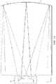
- FIG. 1Ais a schematic diagram illustrating a front view of light propagation in one embodiment of a directional display device, in accordance with the present disclosure
- FIG. 1Bis a schematic diagram illustrating a side view of light propagation in one embodiment of the directional display device of FIG. 1A , in accordance with the present disclosure
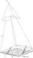
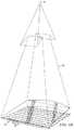
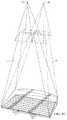
- FIG. 2Ais a schematic diagram illustrating in a top view of light propagation in another embodiment of a directional display device, in accordance with the present disclosure
- FIG. 2Bis a schematic diagram illustrating light propagation in a front view of the directional display device of FIG. 2A , in accordance with the present disclosure
- FIG. 2Cis a schematic diagram illustrating light propagation in a side view of the directional display device of FIG. 2A , in accordance with the present disclosure
- FIG. 3is a schematic diagram illustrating in a side view of a directional display device, in accordance with the present disclosure
- FIG. 4Ais schematic diagram illustrating in a front view, generation of a viewing window in a directional display device and including curved light extraction features, in accordance with the present disclosure
- FIG. 4Bis a schematic diagram illustrating in a front view, generation of a first and a second viewing window in a directional display device and including curved light extraction features, in accordance with the present disclosure
- FIG. 5is a schematic diagram illustrating generation of a first viewing window in a directional display device including linear light extraction features, in accordance with the present disclosure
- FIG. 6Ais a schematic diagram illustrating one embodiment of the generation of a first viewing window in a time multiplexed directional display device, in accordance with the present disclosure
- FIG. 6Bis a schematic diagram illustrating another embodiment of the generation of a second viewing window in a time multiplexed directional display device in a second time slot, in accordance with the present disclosure
- FIG. 6Cis a schematic diagram illustrating another embodiment of the generation of a first and a second viewing window in a time multiplexed directional display device, in accordance with the present disclosure
- FIG. 7is a schematic diagram illustrating an observer tracking autostereoscopic directional display device, in accordance with the present disclosure.
- FIG. 8is a schematic diagram illustrating a multi-viewer directional display device, in accordance with the present disclosure.
- FIG. 9is a schematic diagram illustrating a privacy directional display device, in accordance with the present disclosure.
- FIG. 10is a schematic diagram illustrating in side view, the structure of a directional display device, in accordance with the present disclosure.
- FIG. 11is a schematic diagram illustrating a front view of a wedge type directional backlight, in accordance with the present disclosure.
- FIG. 12is a schematic diagram illustrating a side view of a wedge type directional display device, in accordance with the present disclosure.
- FIG. 13is a schematic diagram illustrating a control system for an observer tracking directional display apparatus, in accordance with the present disclosure
- FIG. 14Ais a schematic diagram illustrating a top view of a directional display including a directional backlight, in accordance with the present disclosure
- FIG. 14Bis a schematic diagram illustrating a graph of optical window luminous intensity against viewing position in the window plane, in accordance with the present disclosure
- FIG. 15Ais a schematic diagram illustrating a graph of optical window luminous intensity against viewing position in the window plane and a method to adjust luminous fluxes of light sources in the array, in accordance with the present disclosure
- FIG. 15Bis a schematic diagram illustrating a graph of luminous flux distribution for an array of light sources and method to adjust luminous fluxes of light sources in the array, in accordance with the present disclosure
- FIG. 15Cis a schematic diagram illustrating a detail of FIG. 15B , in accordance with the present disclosure.
- FIG. 15Dis a schematic diagram illustrating a graph of luminous flux distribution and a front view of a directional backlight aligned with the luminous flux distribution, in accordance with the present disclosure
- FIG. 15Eis a schematic diagram illustrating a graph of luminous flux distribution for an autostereoscopic Lambertian display system, in accordance with the present disclosure.
- FIG. 15Fis a schematic diagram illustrating a graph of luminous flux distribution for an autostereoscopic display system with a gain of greater than one and an on-axis viewing position, in accordance with the present disclosure
- FIG. 15Gis a schematic diagram illustrating a graph of luminous flux distribution for an autostereoscopic display system with a gain of greater than one and an off-axis viewing position, in accordance with the present disclosure
- FIG. 15His a schematic diagram illustrating a further graph of luminous flux distribution for an autostereoscopic display system with a gain of greater than one and an off-axis viewing position, in accordance with the present disclosure
- FIG. 16is a schematic diagram illustrating a light source addressing apparatus, in accordance with the present disclosure.
- FIG. 17is a schematic diagram illustrating a graph of luminous intensity for an array of optical windows and respective optical windows, in accordance with the present disclosure
- FIG. 18is a schematic diagram illustrating a graph of optical window luminous intensity against viewing position for a waveguide including uniform luminous intensity of light sources, in accordance with the present disclosure
- FIG. 19Ais a schematic diagram illustrating a perspective view of a light ray incident with a first direction onto a light extraction feature of a waveguide, in accordance with the present disclosure
- FIG. 19Bis a schematic diagram illustrating a perspective view of a light ray incident with a second direction onto a light extraction feature of a waveguide, in accordance with the present disclosure
- FIG. 20Ais a schematic diagram illustrating a graph of optical window luminous intensity against viewing position in the window plane of a waveguide and a method to adjust luminous fluxes of light sources in the array, in accordance with the present disclosure
- FIG. 20Bis a schematic diagram illustrating a graph of luminous flux distribution for an array of light sources and method to adjust luminous fluxes of light sources in the array for a waveguide, in accordance with the present disclosure
- FIG. 21Ais a schematic diagram illustrating a graph of optical window luminous intensity against viewing position in the window plane of a waveguide and a method to adjust luminous fluxes of light sources in the array, in accordance with the present disclosure
- FIG. 21Bis a schematic diagram illustrating a graph of luminous flux distribution for an array of light sources and method to adjust luminous fluxes of light sources in the array for a waveguide, in accordance with the present disclosure
- FIG. 22is a schematic diagram illustrating a graph of optical window luminous intensity against viewing position in the window plane and a method to adjust luminous fluxes of light sources in the array for left and right eye illumination phases, in accordance with the present disclosure
- FIG. 23Ais a schematic diagram illustrating a graph of optical window luminous intensity against viewing position in the window plane of a waveguide and a method to adjust luminous fluxes of light sources in the array for the right eye illumination phase, in accordance with the present disclosure
- FIG. 23Bis a schematic diagram illustrating a graph of luminous flux distribution for an array of light sources for left and right eye illumination phases and method to adjust luminous fluxes of light sources in the array for a waveguide for the right eye illumination phase, in accordance with the present disclosure
- FIG. 24is a schematic diagram illustrating a graph of optical window luminous intensity against viewing position in the window plane of a waveguide, in accordance with the present disclosure
- FIG. 25is a schematic diagram illustrating a further graph of optical window luminous intensity against viewing position in the window plane of a waveguide, in accordance with the present disclosure
- FIG. 26Ais a schematic diagram illustrating a further graph of optical window luminous intensity against viewing position in the window plane of a waveguide, in accordance with the present disclosure
- FIG. 26Bis a schematic diagram illustrating a graph of luminous flux distribution for an array of light sources to compensate for light source degradation, in accordance with the present disclosure
- FIG. 27Ais a schematic diagram illustrating a front view of a directional display apparatus in landscape mode, in accordance with the present disclosure
- FIG. 27Bis a schematic diagram illustrating a front view of a directional display apparatus in portrait mode, in accordance with the present disclosure
- FIG. 27Cis a schematic diagram illustrating a further graph of optical window luminous intensity against viewing position in the window plane of a waveguide for the arrangement of FIG. 27B , in accordance with the present disclosure
- FIG. 28is a schematic diagram illustrating a side view of a waveguide and viewing windows for observer movement, in accordance with the present disclosure
- FIG. 29is a schematic diagram illustrating a graph of luminous flux distribution for an array of light sources and method to adjust luminous fluxes of light sources in the array for a waveguide with the viewer movement of FIG. 28 , in accordance with the present disclosure
- FIG. 30is a schematic diagram illustrating an arrangement of viewing windows during observer motion between viewing positions in accordance with the present disclosure
- FIG. 31is a schematic diagram illustrating intensity distribution of an arrangement of viewing windows in accordance with the present disclosure.
- FIG. 32is a schematic diagram illustrating a further intensity distribution of an arrangement of viewing windows in accordance with the present disclosure
- FIG. 33is a schematic diagram illustrating a further intensity distribution of an arrangement of viewing windows in accordance with the present disclosure.
- FIG. 34is a schematic diagram illustrating a further intensity distribution of an arrangement of viewing windows in accordance with the present disclosure.
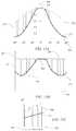
- FIG. 35is a schematic diagram illustrating non-uniformities of display illumination arising from a non-uniform window intensity distribution in accordance with the present disclosure
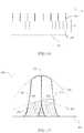
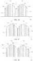
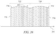
- FIGS. 36-41are schematic diagrams illustrating non-uniform luminous flux distributions from light sources, in accordance with the present disclosure
- FIG. 42is a schematic diagram illustrating a 2D directional display in landscape orientation, in accordance with the present disclosure.
- FIG. 43is a schematic diagram illustrating a graph of scaled luminous flux against light source position for the display of FIG. 42 , in accordance with the present disclosure
- FIG. 44is a schematic diagram illustrating a 2D directional display in portrait orientation, in accordance with the present disclosure.
- FIG. 45is a schematic diagram illustrating a graph of scaled luminous flux against light source position for the display of FIG. 44 , in accordance with the present disclosure
- FIG. 46is a schematic diagram illustrating a control system and front view of a directional backlight apparatus, in accordance with the present disclosure
- FIG. 47is a schematic diagram illustrating a control system and front view of a directional backlight apparatus, in accordance with the present disclosure
- FIG. 48is a schematic diagram illustrating an apparatus to drive a light source for a calibration mode of operation, in accordance with the present disclosure
- FIG. 49is a schematic diagram illustrating a light source array in calibration mode of operation; in accordance with the present disclosure.
- FIG. 50is a schematic diagram illustrating a front view of a light source array arranged to achieve color correction, in accordance with the present disclosure
- FIG. 51is a schematic diagram illustrating a front view of a further light source array arranged to achieve color correction, in accordance with the present disclosure
- FIG. 52is a schematic diagram illustrating a graph of optical window chromaticity variations and a method to correct chromaticity variations, in accordance with the present disclosure
- FIG. 53is a schematic diagram illustrating a front view of a light source array, in accordance with the present disclosure.
- FIG. 54is a schematic diagram illustrating a front view of a light source array and method to correct a light source failure, in accordance with the present disclosure.
- Time multiplexed autostereoscopic displayscan advantageously improve the spatial resolution of autostereoscopic display by directing light from all of the pixels of a spatial light modulator to a first viewing window in a first time slot, and all of the pixels to a second viewing window in a second time slot.
- Time multiplexed displayscan advantageously achieve directional illumination by directing an illuminator array through a substantially transparent time multiplexed spatial light modulator using directional optical elements, wherein the directional optical elements substantially form an image of the illuminator array in the window plane.
- the uniformity of the viewing windowsmay be advantageously independent of the arrangement of pixels in the spatial light modulator.
- Such displayscan provide observer tracking displays which have low flicker, with low levels of cross talk for a moving observer.
- the illuminator elements of the time sequential illumination systemmay be provided, for example, by pixels of a spatial light modulator with size approximately 100 micrometers in combination with a lens array.
- pixelssuffer from similar difficulties as for spatially multiplexed displays. Further, such devices may have low efficiency and higher cost, requiring additional display components.
- High window plane uniformitycan be conveniently achieved with macroscopic illuminators, for example, an array of LEDs in combination with homogenizing and diffusing optical elements that are typically of size 1 mm or greater.
- the increased size of the illuminator elementsmeans that the size of the directional optical elements increases proportionately. For example, a 16 mm wide illuminator imaged to a 65 mm wide viewing window may require a 200 mm back working distance.
- the increased thickness of the optical elementscan prevent useful application, for example, to mobile displays, or large area displays.
- optical valves as described in commonly-owned U.S. patent application Ser. No. 13/300,293advantageously can be arranged in combination with fast switching transmissive spatial light modulators to achieve time multiplexed autostereoscopic illumination in a thin package while providing high resolution images with flicker free observer tracking and low levels of cross talk.
- Describedis a one dimensional array of viewing positions, or windows, that can display different images in a first, typically horizontal, direction, but contain the same images when moving in a second, typically vertical, direction.
- imaging directional backlightsare arranged to direct the illumination from multiple light sources through a display panel to respective multiple optical windows in at least one axis.
- Each optical windowis substantially formed as an image in at least one axis of a light source by the imaging system of the imaging directional backlight.
- An imaging systemmay be formed to image multiple light sources to respective viewing windows. In this manner, the light from each of the multiple light sources is substantially not visible for an observer's eye outside of the respective viewing window.
- Non-imaging backlightsare typically arranged to direct the illumination from multiple light sources through a display panel into a substantially common viewing zone for each of the multiple light sources to achieve wide viewing angle and high display uniformity.
- non-imaging backlightsdo not form viewing windows. In this manner, the light from each of the multiple light sources may be visible for an observer's eye at substantially all positions across the viewing zone.
- Such conventional non-imaging backlightsmay have some directionality, for example, to increase screen gain compared to Lambertian illumination, which may be provided by brightness enhancement films such as BEFTM from 3M. However, such directionality may be substantially the same for each of the respective light sources. Thus, for these reasons and others that should be apparent to persons of ordinary skill, conventional non-imaging backlights are different to imaging directional backlights.
- Edge lit non-imaging backlight illumination structuresmay be used in liquid crystal display systems such as those seen in 2D Laptops, Monitors and TVs. Light propagates from the edge of a lossy waveguide which may include sparse features; typically local indentations in the surface of the guide which cause light to be lost regardless of the propagation direction of the light.
- an optical valveis an optical structure that may be a type of light guiding structure or device referred to as, for example, a light valve, an optical valve directional backlight, and a valve directional backlight (“v-DBL”).
- optical valveis different to a spatial light modulator (even though spatial light modulators may be sometimes generally referred to as a “light valve” in the art).
- One example of an imaging directional backlightis an optical valve that may employ a folded optical system. Light may propagate substantially without loss in one direction through the optical valve, may be incident on an imaging reflector, and may counter-propagate such that the light may be extracted by reflection off tilted light extraction features, and directed to viewing windows as described in patent application Ser. No. 13/300,293, which is herein incorporated by reference in its entirety.
- an imaging directional backlightexamples include a stepped waveguide imaging directional backlight, a folded imaging directional backlight, a wedge type directional backlight, or an optical valve.
- a stepped waveguide imaging directional backlightmay be an optical valve.
- a stepped waveguideis a waveguide for an imaging directional backlight including a waveguide for guiding light, further including a first light guiding surface; and a second light guiding surface, opposite the first light guiding surface, further including a plurality of guiding features interspersed with a plurality of extraction features arranged as steps.
- a folded imaging directional backlightmay be at least one of a wedge type directional backlight, or an optical valve.
- lightmay propagate within an exemplary optical valve in a first direction from an input end to a reflective end and may be transmitted substantially without loss.
- Lightmay be reflected at the reflective end and propagates in a second direction substantially opposite the first direction.
- the lightmay be incident on light extraction features, which are operable to redirect the light outside the optical valve.
- the optical valvegenerally allows light to propagate in the first direction and may allow light to be extracted while propagating in the second direction.
- the optical valvemay achieve time sequential directional illumination of large display areas. Additionally, optical elements may be employed that are thinner than the back working distance of the optical elements to direct light from macroscopic illuminators to a nominal window plane. Such displays may use an array of light extraction features arranged to extract light counter propagating in a substantially parallel waveguide.
- Thin imaging directional backlight implementations for use with LCDshave been proposed and demonstrated by 3M, for example U.S. Pat. No. 7,528,893; by Microsoft, for example U.S. Pat. No. 7,970,246 which may be referred to herein as a “wedge type directional backlight;” by RealD, for example U.S. patent application Ser. No. 13/300,293 which may be referred to herein as an “optical valve” or “optical valve directional backlight,” all of which are herein incorporated by reference in their entirety.
- the present disclosureprovides stepped waveguide imaging directional backlights in which light may reflect back and forth between the internal faces of, for example, a stepped waveguide which may include a first guide surface and a second guide surface comprising a plurality of light extraction features and intermediate regions.
- a stepped waveguidewhich may include a first guide surface and a second guide surface comprising a plurality of light extraction features and intermediate regions.
- the lightmay not substantially change angle of incidence with respect to the first and second guide surfaces and so may not reach the critical angle of the medium at these internal surfaces.
- Light extractionmay be advantageously achieved by a light extraction features which may be facets of the second guide surface (the step “risers”) that are inclined to the intermediate regions (the step “treads”).
- the light extraction featuresmay not be part of the light guiding operation of the stepped waveguide, but may be arranged to provide light extraction from the structure.
- a wedge type imaging directional backlightmay allow light to guide within a wedge profiled waveguide having continuous internal surfaces.
- the stepped waveguideoptical valve
- the stepped waveguideis thus not a wedge type imaging directional backlight.
- FIG. 1Ais a schematic diagram illustrating a front view of light propagation in one embodiment of a directional display device
- FIG. 1Bis a schematic diagram illustrating a side view of light propagation in the directional display device of FIG. 1A .
- FIG. 1Aillustrates a front view in the xy plane of a directional backlight of a directional display device, and includes an illuminator array 15 which may be used to illuminate a stepped waveguide 1 .
- Illuminator array 15includes illuminator elements 15 a through illuminator element 15 n (where n is an integer greater than one).
- the stepped waveguide 1 of FIG. 1Amay be a stepped, display sized waveguide 1 .
- Illuminator elements 15 a through 15 nare light sources that may be light emitting diodes (LEDs).
- FIG. 1Billustrates a side view in the xz plane, and includes illuminator array 15 , SLM (spatial light modulator) 48 , extraction features 12 , intermediate regions 10 , and stepped waveguide 1 , arranged as shown.
- the side view provided in FIG. 1Bis an alternative view of the front view shown in FIG. 1A . Accordingly, the illuminator array 15 of FIGS. 1A and 1B corresponds to one another and the stepped waveguide 1 of FIGS. 1A and 1B may correspond to one another.
- the stepped waveguide 1may have an input end 2 that is thin and a reflective end 4 that is thick.
- the waveguide 1extends between the input end 2 that receives input light and the reflective end 4 that reflects the input light back through the waveguide 1 .
- the length of the input end 2 in a lateral direction across the waveguideis greater than the height of the input end 2 .
- the illuminator elements 15 a - 15 nare disposed at different input positions in a lateral direction across the input end 2 .
- the waveguide 1has first and second, opposed guide surfaces extending between the input end 2 and the reflective end 4 for guiding light forwards and back along the waveguide 1 by total internal reflection (TIR).
- the first guide surfaceis planar.
- the second guide surfacehas a plurality of light extraction features 12 facing the reflective end 4 and inclined to reflect at least some of the light guided back through the waveguide 1 from the reflective end in directions that break the total internal reflection at the first guide surface and allow output through the first guide surface, for example, upwards in FIG. 1B , that is supplied to the SLM 48 .
- the light extraction features 12are reflective facets, although other reflective features could be used.
- the light extraction features 12do not guide light through the waveguide, whereas the intermediate regions of the second guide surface intermediate the light extraction features 12 guide light without extracting it. Those regions of the second guide surface are planar and may extend parallel to the first guide surface, or at a relatively low inclination.
- the light extraction features 12extend laterally to those regions so that the second guide surface has a stepped shape including of the light extraction features 12 and intermediate regions.
- the light extraction features 12are oriented to reflect light from the light sources, after reflection from the reflective end 4 , through the first guide surface.
- the light extraction features 12are arranged to direct input light from different input positions in the lateral direction across the input end in different directions relative to the first guide surface that are dependent on the input position.
- the illumination elements 15 a - 15 nare arranged at different input positions, the light from respective illumination elements 15 a - 15 n is reflected in those different directions.
- each of the illumination elements 15 a - 15 ndirects light into a respective optical window in output directions distributed in the lateral direction in dependence on the input positions.
- the lateral direction across the input end 2 in which the input positions are distributedcorresponds with regard to the output light to a lateral direction to the normal to the first guide surface.
- the illuminator elements 15 a - 15 nmay be selectively operated to direct light into a selectable optical window.
- the optical windowsmay be used individually or in groups as viewing windows.
- an optical windowmay correspond to the image of a single light source in the window plane, being a nominal plane in which optical windows form across the entirety of the display device.
- an optical windowmay correspond to the image of a groups of light sources that are driven together.
- such groups of light sourcesmay increase uniformity of the optical windows of the array 121 .
- a viewing windowis a region in the window plane wherein light is provided comprising image data of substantially the same image from across the display area.
- a viewing windowmay be formed from a single optical window or from plural optical windows, under the control of the control system.
- the SLM 48extends across the waveguide is transmissive and modulates the light passing therethrough.
- the SLM 48may be a liquid crystal display (LCD) but this is merely by way of example, and other spatial light modulators or displays may be used including LCOS, DLP devices, and so forth, as this illuminator may work in reflection.
- the SLM 48is disposed across the first guide surface of the waveguide and modulates the light output through the first guide surface after reflection from the light extraction features 12 .
- FIG. 1AThe operation of a directional display device that may provide a one dimensional array of optical windows is illustrated in front view in FIG. 1A , with its side profile shown in FIG. 1B .
- the lightmay propagate along +x in a first direction, within the stepped waveguide 1 , while at the same time, the light may fan out in the xy plane and upon reaching the reflective end 4 that is curved to have a positive optical power in the lateral direction, may substantially or entirely fill the curved end side 4 . While propagating, the light may spread out to a set of angles in the xz plane up to, but not exceeding the critical angle of the guide material.
- the extraction features 12 that link the intermediate regions 10 of the second guide surface of the stepped waveguide 1may have a tilt angle greater than the critical angle and hence may be missed by substantially all light propagating along +x in the first direction, ensuring the substantially lossless forward propagation.
- the reflective end 4 of the stepped waveguide 1may be made reflective, typically by being coated with a reflective material such as, for example, silver, although other reflective techniques may be employed.
- Lightmay therefore be redirected in a second direction, back down the guide in the direction of ⁇ x and may be substantially collimated in the xy or display plane.
- the angular spreadmay be substantially preserved in the xz plane about the principal propagation direction, which may allow light to hit the riser edges and reflect out of the guide.
- lightmay be effectively directed approximately normal to the xy display plane with the xz angular spread substantially maintained relative to the propagation direction. This angular spread may be increased when light exits the stepped waveguide 1 through refraction, but may be decreased somewhat dependent on the reflective properties of the extraction features 12 .
- reflectionmay be reduced when total internal reflection (TIR) fails, squeezing the xz angular profile and shifting off normal.
- TIRtotal internal reflection
- the increased angular spread and central normal directionmay be preserved.
- lightmay exit the stepped waveguide 1 approximately collimated and may be directed off normal in proportion to the y-position of the respective illuminator element 15 a - 15 n in illuminator array 15 from the input edge center. Having independent illuminator elements 15 a - 15 n along the input end 2 then enables light to exit from the entire first guide surface 6 and propagate at different external angles, as illustrated in FIG. 1A .
- Illuminating a spatial light modulator (SLM) 48 such as a fast liquid crystal display (LCD) panel with such a devicemay achieve autostereoscopic 3D as shown in top view or yz-plane viewed from the illuminator array 15 end in FIG. 2A , front view in FIG. 2B and side view in FIG. 2C .
- FIG. 2Ais a schematic diagram illustrating in a top view, propagation of light in a directional display device
- FIG. 2Bis a schematic diagram illustrating in a front view, propagation of light in a directional display device
- FIG. 2Cis a schematic diagram illustrating in side view propagation of light in a directional display device.
- FIGS. 1spatial light modulator
- a stepped waveguide 1may be located behind a fast e.g., greater than 100 Hz) LCD panel SLM 48 that displays sequential right and left eye images.
- a fast e.g., greater than 100 Hz LCD panel SLM 48that displays sequential right and left eye images.
- specific illuminator elements 15 a through 15 n of illuminator array 15may be selectively turned on and off, providing illuminating light that enters right and left eyes substantially independently by virtue of the system's directionality.
- sets of illuminator elements of illuminator array 15are turned on together, providing a one dimensional viewing window 26 or an optical pupil with limited width in the horizontal direction, but extended in the vertical direction, in which both eyes horizontally separated may view a left eye image, and another viewing window 44 in which a right eye image may primarily be viewed by both eyes, and a central position in which both the eyes may view different images.
- Viewing window 26may comprise an array of optical windows 260 and viewing window 44 may comprise an array of optical windows 440 , wherein each optical window is formed by a single illuminator of the array 15 .
- multiple illuminatorsmay be arranged to form viewing windows 26 and 44 .
- the viewing window 26is shown as formed by a single illuminator 15 a and may thus comprise a single optical window 260 .
- the viewing window 44is shown as formed by a single illuminator 15 n and may thus comprise a single optical window 440 .
- 3Dmay be viewed when the head of a viewer is approximately centrally aligned. Movement to the side away from the central position may result in the scene collapsing onto a 2D image.
- the reflective end 4may have positive optical power in the lateral direction across the waveguide.
- the optical axismay be defined with reference to the shape of the reflective end 4 , for example being a line that passes through the centre of curvature of the reflective end 4 and coincides with the axis of reflective symmetry of the end 4 about the x-axis.
- the optical axismay be similarly defined with respect to other components having optical power, for example the light extraction features 12 if they are curved, or the Fresnel lens 62 described below.
- the optical axis 238is typically coincident with the mechanical axis of the waveguide 1 .
- the optical axis 238is a line that passes through the centre of curvature of the surface at end 4 and coincides with the axis of reflective symmetry of the side 4 about the x-axis.
- the optical axis 238is typically coincident with the mechanical axis of the waveguide 1 .
- the cylindrical reflecting surface at end 4may typically be a spherical profile to optimize performance for on-axis and off-axis viewing positions. Other profiles may be used.
- FIG. 3is a schematic diagram illustrating in side view a directional display device. Further. FIG. 3 illustrates additional detail of a side view of the operation of a stepped waveguide 1 , which may be a transparent material.
- the stepped waveguide 1may include an illuminator input end 2 , a reflective end 4 , a first guide surface 6 which may be substantially planar, and a second guide surface 8 which includes intermediate regions 10 and light extraction features 12 .
- light rays 16 from an illuminator element 15 c of an illuminator array 15(not shown in FIG.
- reflective end 4may be a mirrored surface and may reflect light, it may in some embodiments also be possible for light to pass through reflective end 4 .
- light ray 18 reflected by the reflective end 4may be further guided in the stepped waveguide 1 by total internal reflection at the reflective end 4 and may be reflected by extraction features 12 .
- Light rays 18 that are incident on extraction features 12may be substantially deflected away from guiding modes of the stepped waveguide 1 and may be directed, as shown by ray 20 , through the first guide surface 6 to an optical pupil that may form a viewing window 26 of an autostereoscopic display.
- the width of the viewing window 26may be determined by at least the size of the illuminator, number of illuminator elements 15 n illuminated, output design distance and optical power in the reflective end 4 and extraction features 12 .
- each viewing window 26represents a range of separate output directions with respect to the surface normal direction of the spatial light modulator 48 that intersect with a window plane 106 at the nominal viewing distance.
- FIG. 4Ais a schematic diagram illustrating in front view a directional display device which may be illuminated by a first illuminator element and including curved light extraction features. Further, FIG. 4A shows in front view further guiding of light rays from illuminator element 15 c of illuminator array 15 , in the stepped waveguide 1 having an optical axis 28 .
- the directional backlightmay include the stepped waveguide 1 and the light source illuminator array 15 .
- Each of the output raysare directed from the input end 2 towards the same optical window 260 from the respective illuminator 15 c .
- the light rays of FIG. 4Amay exit the reflective end 4 of the stepped waveguide 1 .
- ray 16may be directed from the illuminator element 15 c towards the reflective end 4 .
- Ray 18may then reflect from a light extraction feature 12 and exit the reflective end 4 towards the optical window 260 .
- light ray 30may intersect the ray 20 in the optical window 260 , or may have a different height in the viewing window as shown by ray 32 .
- sides 22 , 24 of the waveguide 1may be transparent, mirrored, or blackened surfaces.
- light extraction features 12may be elongate, and the orientation of light extraction features 12 in a first region 34 of the second guide surface 8 (shown in FIG. 3 , but not shown in FIG.
- the stepped waveguide 1may include a reflective surface on reflective end 4 .
- the reflective end of the stepped waveguide 1may have positive optical power in a lateral direction across the stepped waveguide 1 .
- the light extraction features 12 of each directional backlightmay have positive optical power in a lateral direction across the waveguide.
- each directional backlightmay include light extraction features 12 which may be facets of the second guide surface.
- the second guide surfacemay have regions alternating with the facets that may be arranged to direct light through the waveguide without substantially extracting it.
- FIG. 4Bis a schematic diagram illustrating in front view a directional display device which may illuminated by a second illuminator element. Further, FIG. 4B shows the light rays 40 , 42 from a second illuminator element 15 h of the illuminator array 15 .
- the curvature of the reflective surface on the reflective end 4 and the light extraction features 12cooperatively produce a second optical window 440 laterally separated from the optical window 260 with light rays from the illuminator element 15 h.
- the arrangement illustrated in FIG. 4Bmay provide a real image of the illuminator element 15 c at an optical window 260 in which the real image may be formed by cooperation of optical power in reflective end 4 and optical power which may arise from different orientations of elongate light extraction features 12 between regions 34 and 36 , as shown in FIG. 4A .
- the arrangement of FIG. 4Bmay achieve improved aberrations of the imaging of illuminator element 15 c to lateral positions in optical window 260 . Improved aberrations may achieve an extended viewing freedom for an autostereoscopic display while achieving low cross talk levels.
- FIG. 5is a schematic diagram illustrating in front view an embodiment of a directional display device having substantially linear light extraction features. Further, FIG. 5 shows a similar arrangement of components to FIG. 1 (with corresponding elements being similar), with one of the differences being that the light extraction features 12 are substantially linear and parallel to each other. Advantageously, such an arrangement may provide substantially uniform illumination across a display surface and may be more convenient to manufacture than the curved extraction features of FIG. 4A and FIG. 4B .
- the optical axis 321 of the directional waveguide 1may be the optical axis direction of the surface at the reflective end 4 .
- the optical power of the reflective end 4is arranged to be across the optical axis direction, thus rays incident on the reflective end 4 will have an angular deflection that varies according to the lateral offset 319 of the incident ray from the optical axis 321 .
- FIG. 6Ais a schematic diagram illustrating one embodiment of the generation of a first viewing window in a time multiplexed imaging directional display device in a first time slot
- FIG. 6Bis a schematic diagram illustrating another embodiment of the generation of a second viewing window in a time multiplexed imaging directional backlight apparatus in a second time slot
- FIG. 6Cis a schematic diagram illustrating another embodiment of the generation of a first and a second viewing window in a time multiplexed imaging directional display device.
- FIG. 6Ashows schematically the generation of viewing window 26 from stepped waveguide 1 .
- Illuminator element group 31 in illuminator array 15may provide a light cone 17 directed towards a viewing window 26 (that may comprise a single optical window 260 or an array of optical windows 260 ).
- FIG. 6Bshows schematically the generation of viewing window 44 .
- Illuminator element group 33 in illuminator array 15may provide a light cone 19 directed towards viewing window 44 (that may comprise a single optical window 440 or an array of optical windows 440 ).
- viewing windows 26 and 44may be provided in sequence as shown in FIG. 6C . If the image on a spatial light modulator 48 (not shown in FIGS.
- illuminator element groups 31 , 33each include one or more illumination elements from illumination elements 15 a to 15 n , where n is an integer greater than one.
- FIG. 7is a schematic diagram illustrating one embodiment of an observer tracking autostereoscopic display apparatus including a time multiplexed directional display device.
- selectively turning on and off illuminator elements 15 a to 15 n along axis 29provides for directional control of viewing windows 26 , 44 .
- the head 45 positionmay be monitored with a camera, motion sensor, motion detector, or any other appropriate optical, mechanical or electrical means, and the appropriate illuminator elements of illuminator array 15 may be turned on and off to provide substantially independent images to each eye irrespective of the head 45 position.
- the head tracking system(or a second head tracking system) may provide monitoring of more than one head 45 , 47 (head 47 not shown in FIG. 7 ) and may supply the same left and right eye images to each viewers' left and right eyes providing 3D to all viewers. Again similar operation can be achieved with all the imaging directional backlights described herein.
- FIG. 8is a schematic diagram illustrating one embodiment of a multi-viewer directional display device as an example including an imaging directional backlight.
- at least two 2D imagesmay be directed towards a pair of viewers 45 , 47 so that each viewer may watch a different image on the spatial light modulator 48 .
- the two 2D images of FIG. 8may be generated in a similar manner as described with respect to FIG. 7 in that the two images would be displayed in sequence and in synchronization with sources whose light is directed toward the two viewers.
- One imageis presented on the spatial light modulator 48 in a first phase
- a second imageis presented on the spatial light modulator 48 in a second phase different from the first phase.
- the output illuminationis adjusted to provide first and second viewing windows 26 , 44 respectively. An observer with both eyes in viewing window 26 will perceive a first image while an observer with both eyes in viewing window 44 will perceive a second image.
- FIG. 9is a schematic diagram illustrating a privacy directional display device which includes an imaging directional backlight
- 2D display systemsmay also utilize directional backlighting for security and efficiency purposes in which light may be primarily directed at the eyes of a first viewer 45 as shown in FIG. 9 .
- first viewer 45may be able to view an image on device 50
- lightis not directed towards second viewer 47 .
- second viewer 47is prevented from viewing an image on device 50 .
- Each of the embodiments of the present disclosuremay advantageously provide autostereoscopic, dual image or privacy display functions.
- FIG. 10is a schematic diagram illustrating in side view the structure of a time multiplexed directional display device as an example including an imaging directional backlight. Further, FIG. 10 shows in side view an autostereoscopic directional display device, which may include the stepped waveguide 1 and a Fresnel lens 62 arranged to provide the viewing window 26 for a substantially collimated output across the stepped waveguide 1 output surface.
- a vertical diffuser 68may be arranged to extend the height of the viewing window 26 further and to achieve blurring in directions in the vertical direction (parallel to the x-axis) while minimizing blurring in directions in the lateral direction (y axis). The light may then be imaged through the spatial light modulator 48 .
- the illuminator array 15may include light emitting diodes (LEDs) that may, for example, be phosphor converted blue LEDs, or may be separate RGB LEDs.
- the illuminator elements in illuminator array 15may include a uniform light source and spatial light modulator arranged to provide separate illumination regions.
- the illuminator elementsmay include laser light source(s).
- the laser outputmay be directed onto a diffuser by means of scanning, for example, using a galvo or MEMS scanner.
- laser lightmay thus be used to provide the appropriate illuminator elements in illuminator array 15 to provide a substantially uniform light source with the appropriate output angle, and further to provide reduction in speckle.
- the illuminator array 15may be an array of laser light emitting elements.
- the diffusermay be a wavelength converting phosphor, so that illumination may be at a different wavelength to the visible output light.
- FIGS. 1 to 10variously describe: a waveguide 1 ; a directional backlight comprising such a waveguide 1 and an illuminator array 15 ; and a directional display device including such a directional backlight and an SLM 48 .
- a waveguide 1a waveguide 1 ; a directional backlight comprising such a waveguide 1 and an illuminator array 15 ; and a directional display device including such a directional backlight and an SLM 48 .
- FIG. 11is a schematic diagram illustrating a front view of another imaging directional backlight, as illustrated, a wedge type directional backlight
- FIG. 12is a schematic diagram illustrating a side view of a similar wedge type directional display device.
- a wedge type directional backlightis generally discussed by U.S. Pat. No. 7,660,047 and entitled “Flat Panel Lens,” which is herein incorporated by reference in its entirety.
- the structuremay include a wedge type waveguide 1104 with a bottom surface which may be preferentially coated with a reflecting layer 1106 and with an end corrugated surface 1102 , which may also be preferentially coated with a reflecting layer 1106 .
- a directional display devicemay include a waveguide having an input end, first and second opposed guide surfaces for guiding light along the waveguide, and a reflective end facing the input end for reflecting light from the input light back through the waveguide.
- the directional display devicemay also include an array of light sources disposed at different input positions across the input end of the waveguide.
- the waveguidemay be arranged to direct input light from the light sources as output light through the first guide surface after reflection from the reflective end into optical windows in output directions relative to the normal to the first guide surface and may be primarily dependent on the input positions.
- the directional display devicemay also include a transmissive spatial light modulator arranged to receive the output light from the first guide surface and arranged to modulate a first polarization component of the output light having a first polarization.
- the first guide surfacemay be arranged to guide light by total internal reflection and the second guide surface may be substantially planar and inclined at an angle to reflect light in directions that break the total internal reflection for outputting light through the first guide surface.
- the wedge type directional backlightmay be part of a directional display device.
- the directional display devicemay also include a deflection element extending across the first guide surface of the waveguide for deflecting light towards the normal to the spatial light modulator.
- lightmay enter the wedge type waveguide 1104 from local sources 1101 and the light may propagate in a first direction before reflecting off the end surface.
- Lightmay exit the wedge type waveguide 1104 while on its return path and may illuminate a display panel 1110 .
- a wedge type waveguideprovides extraction by a taper that reduces the incidence angle of propagating light so that when the light is incident at the critical angle on an output surface, it may escape. Escaping light at the critical angle in the wedge type waveguide propagates substantially parallel to the surface until deflected by a redirection layer 1108 such as a prism array. Errors or dust on the wedge type waveguide output surface may change the critical angle, creating stray light and uniformity errors.
- an imaging directional backlight that uses a mirror to fold the beam path in the wedge type directional backlightmay employ a faceted mirror that biases the light cone directions in the wedge type waveguide.
- Such faceted mirrorsare generally complex to fabricate and may result in illumination uniformity errors as well as stray light.
- the wedge type directional backlight and optical valvefurther process light beams in different ways.
- light input at an appropriate anglewill output at a defined position on a major surface, but light rays will exit at substantially the same angle and substantially parallel to the major surface.
- light input to a stepped waveguide of an optical valve at a certain anglemay output from points across the first side, with output angle determined by input angle.
- the stepped waveguide of the optical valvemay not require further light re-direction films to extract light towards an observer and angular non-uniformities of input may not provide non-uniformities across the display surface.
- a wedge type waveguidesuch as wedge type waveguide 1104 may be used in a directional backlight, and may replace the stepped waveguide 1 in the various structures shown in FIGS. 1 to 10 described above and in the structures described below.
- the directional display deviceincludes a directional backlight including a waveguide and an SLM.
- the waveguides, directional backlights and directional display devicesare based on and incorporate the structures of FIGS. 1 to 10 above, but could equally be adapted to replace the stepped waveguide 1 by a wedge type waveguide as described above. Except for the modifications and/or additional features which will now be described, the above description applies equally to the following waveguides, directional backlights and display devices, but for brevity will not be repeated.
- FIG. 13is a schematic diagram illustrating a directional display apparatus including a display device 100 and a control system. The arrangement and operation of the control system will now be described and may be applied, with changes as necessary, to each of the display devices disclosed herein.
- the directional display device 100includes a directional backlight that includes waveguide 1 and an array 15 of illuminator elements 15 n arranged as described above.
- the control systemis arranged to selectively operate the illumination elements 15 a - 15 n to direct light into selectable optical windows.
- the waveguide 1is arranged as described above.
- the reflective end 4converges the reflected light.
- a Fresnel lens 62may be arranged to cooperate with reflective end 4 to achieve viewing windows 26 at a window plane 106 observed by an observer 99 .
- a transmissive spatial light modulator (SIM) 48may be arranged to receive the light from the directional backlight. Further a diffuser 68 may be provided to substantially remove Moiré beating between the waveguide 1 and pixels of the SLM 48 as well as the Fresnel lens 62 .
- the control systemmay include a sensor system arranged to detect the position of the observer 99 relative to the display device 100 .
- the sensor systemincludes a position sensor 70 , such as a camera, and a head position measurement system 72 that may for example include a computer vision image processing system.
- the control systemmay further include an illumination controller 74 and an image controller 76 that are both supplied with the detected position of the observer supplied from the head position measurement system 72 .
- the illumination controller 74supplies drive signals to the illuminator elements 15 n . By controlling the drive signals, the illumination controller 74 selectively operates the illuminator elements 15 n to direct light to into the viewing windows 26 in cooperation with waveguide 1 .
- the illumination controller 74selects the illuminator elements 15 n to be operated in dependence on the position of the observer detected by the head position measurement system 72 , so that the viewing windows 26 into which light is directed are in positions corresponding to the left and right eyes of the observer 99 . In this manner, the lateral output directionality of the waveguide 1 corresponds with the observer position.
- the illumination controller 74may be arranged to vary the drive signals supplied to respective illuminator element 15 to control the luminous flux of the light emitted by the respective light sources of the array 15 , which may be referred to as the grey level of light.
- the luminous flux of a light sourceis a measure of the optical power emitted by the light source, measured in lumens.
- Control of the luminous fluxmay be effected by any suitable drive scheme including, without limitation, voltage modulation, current modulation, pulse width modulation, control of a spatial light modulator arranged between a light source and the input end 2 , or other known greyscale drive scheme.
- the luminous flux emitted by each illuminator element 15 nmay be varied by altering the current flowing in each addressable device, or by a pulse width modulation scheme where the length of one or more pulses is changed in order to vary the brightness perceived by the observer due to the persistence of vision. It is also possible to combine these two effects to achieve the brightness control desired.
- the image controller 76controls the SLM 48 to display images.
- the image controller 76 and the illumination controller 74may operate as follows.
- the image controller 76controls the SLM 48 to display temporally multiplexed left and right eye images.
- the illumination controller 74operate the light sources 15 to direct light into viewing windows in positions corresponding to the left and right eyes of an observer synchronously with the display of left and right eye images. The position of the viewing windows may primarily depend on the detected position of the observer. In this manner, an autostereoscopic effect is achieved using a time division multiplexing technique.
- a luminous flux controller 580operating under user or automatic control, may control the illumination controller 74 to implement a method of controlling the illuminator elements 15 n of the directional backlight to output light with luminous fluxes, scaled inversely by the width associated with the respective illuminator elements 15 n in the lateral direction, that varies across the array of illuminator elements 15 .
- the quantity of luminous flux that is varied across the array 15is the luminous flux of an individual illuminator 15 that is scaled.
- the scalingis inverse with the width associated with the respective illuminator elements 15 n in the lateral direction.
- the purpose of that scalingis to take account of any variation in the pitch of the illuminator elements 15 n across the array 15 .
- the scaled luminous fluxesare simply the actual luminous fluxes of the illuminator elements 15 n , because the scaling is constant.
- the pitch of the illuminator elements 15 n in the lateral directionis variable, then the scaled luminous fluxes take into account that varying pitch.
- the scaled luminous fluxesmay therefore take into account gaps between the light sources and non-uniformities across luminous flux of the respective outputs.
- the width associated with an illuminator element 15 nmay be taken as the pitch of the array illuminator elements 15 n at the illuminator element 15 n being considered.
- the width associated with an illuminator element 15 nmay be taken as the width between the mid-points of the gaps between the illuminator elements 15 n .
- the scaled luminous fluxis described further in reference to FIG. 53 .
- the scaled luminous fluxesare considered, because in the display device 100 this quantity affects the luminous intensity of the output light as described further below.
- the luminous intensity of the display deviceis a measure of the power emitted by the display device in a particular direction per unit solid angle. Therefore the scaled luminous fluxes are controlled to provide a desired luminous intensity.
- the brightness of the display device 100 as perceived by the observer 99is elicited by the luminance which is a photometric measure of the luminous intensity per unit area of light traveling in a given direction.
- variation of the luminous flux linear densityallows the perceived brightness to be controlled, for example allowing the perceived brightness (luminance) to be varied for different positions of the observer 99 and/or power consumption to be minimized for a given perceived brightness.
- the luminous flux under considerationis the total luminous flux emitted. This may be derived by integrating the luminous flux emitted by the illuminator elements 15 n over the direction perpendicular to the lateral direction.
- the luminous flux controller 580may control the luminous flux to vary across the array of illuminator elements 15 n in a luminous flux distribution that is fixed with respect the position in the lateral direction.
- the luminous flux controller 580may control the luminous flux to vary across the array of illuminator elements 15 n in dependence on the detected position of the observer 99 , as detected by the sensor system.
- the luminous flux controller 580may control the luminous flux to vary across the array of illuminator elements 15 n.
- the luminous flux controller 580controls the scaled luminous fluxes to vary across the array of illuminator elements 15 n in a luminous flux distribution that is fixed with respect the position in the lateral direction.
- Thishas particular advantage when the display device 100 is operated to display a 2D image viewable from a wide angle compared to a directional mode of operation such as an autostereoscopic mode. In that case, all the illuminator elements 15 n may simultaneously be operated, in which case the sensor system might be unused or omitted.
- the illumination controller 74may operate the light sources 15 to direct light into a single viewing window visible by both eyes in dependence on the detected position of the observer with the SLM 48 arranged to operate in a single phase for 2D viewing for privacy and high efficiency modes of operation. Such a viewing window is sufficiently wide to be seen by both the left and right eyes of an observer.
- the fixed luminous flux distributionmay also be applied when the display device is operated to provide an autostereoscopic 3D display.
- FIG. 14Ais a schematic diagram illustrating a top view of a directional backlight that includes waveguide 1 and an array of illuminator elements 15 n that provide an array of optical windows 260 in a window plane 106 , the output direction and hence nominal lateral position in the window plane of each optical window 260 being dependant on the lateral position of the respective illuminator in the array 15 .
- the luminous intensity of the display seen from the optical windows 260may vary with position of an observer 99 (with right and left eye positions 560 , 562 as indicated).
- each element of the array 15 of illuminator elements 15 n and each optical window 260 of the array of optical windowswill comprise the effects of scatter diffusion, diffraction and imaging properties of the optical components arranged between the array 15 and window plane 106 .
- the optical windows 260are not perfect images of the illuminator elements 15 n .
- the lateral position 262 of the optical windows 260will typically be directly related to the lateral position 261 of the illuminator elements 15 n in the array 15 .
- the luminous flux controller 580may control the scaled luminous fluxes to vary across the array of illuminator elements 15 n in a luminous flux distribution with the input position of the illuminator element 15 in the lateral direction, that produces a desired luminance intensity distribution that represents the variation of the luminous intensity of the output light with the angle of the output directions, examples of which will now be described.
- FIG. 14Bis a schematic diagram illustrating a graph of the luminous intensity 264 of the output light against viewing position 262 in the window plane 106 corresponding to the angle ⁇ of the output directions.
- Luminous intensity distribution 266is Lambertian, having a luminous intensity that varies as the cosine of viewing angle ⁇ and so the luminous intensity across the display may vary, while the observed luminance of the display is constant from viewing positions 500 to 502 within the viewing windows.
- a Lambertian emitterachieves the same apparent luminance of a surface independent of the observer's angle of view.
- the surfacehas an isotropic luminance (measured in candela per metre 2 , or lumen per steradian per metre 2 ) and the variation of luminous intensity (measured in candela, or lumen per steradian) 264 obeys Lamberts cosine law wherein luminous intensity observed from an ideal diffuse radiator is directly proportional to the cosine of the angle ⁇ between the observer's line of sight and the surface normal.
- Lambertianis used to describe the emission of a display over a defined angular range, for example the total width of optical windows of the display. Thus at positions in the window plane outside the width of the optical windows, the luminous intensity distribution may behave in a non-Lambertian manner.
- the luminous intensitymay typically be considered for a point on the backlight, for example the point corresponding to the centre of the SLM 48 .
- the luminance (luminous intensity per unit area) of the display systemmay vary across the display area due to non-uniformities of output and will further vary with subtended viewing angle of the respective unit area.
- FIG. 14Bfurther shows a luminous intensity distribution for a luminous intensity distribution 272 having a gain greater than one.
- the luminous intensity distribution 272has a maximum luminous intensity, corresponding to the global maximum of the luminous flux distribution, that is greater than the luminous intensity distribution 266 that is Lambertian, wherein the total power of the two luminous intensity distributions 266 and 272 is the same over all output directions 500 to 502 .
- the peak luminous intensityis greater for on-axis positions, and falls at a faster rate than the luminous intensity distribution 266 that is Lambertian.
- the display luminancefalls for off-axis viewing positions.
- the ratio of luminance of distribution 272 to peak luminance of distribution 266is often referred to as the gain of a display system.
- the luminous flux controller 580may control the scaled luminous fluxes to vary across the array of illuminator elements 15 n in a luminous flux distribution that provides the output light with a luminous intensity distribution 266 that is Lambertian or with a luminous intensity distribution 272 having a gain greater than one, as follows.
- FIG. 15Ais a schematic diagram illustrating a graph of luminous intensity of the output light against viewing position 262 in the window plane 106 corresponding to the lateral angle ⁇ of the output direction with respect to the optical axis 238 , as well as a method to adjust the scaled luminous fluxes of array 15 .
- the luminous intensity distributions 266 and 272are shown but with their peak luminous intensities matched so that the on-axis luminances are matched and the display appears equally bright for on-axis viewing positions.
- the luminous intensity distribution 266 that is Lambertianmay be achieved by controlling all of the illuminator elements of array 15 to have substantially the same scaled luminous flux output.
- the luminous intensity for off-axis positionsmay be reduced in comparison to the distribution 266 , as indicated by arrows 270 .
- Thismay be achieved by controlling the scaled luminous fluxes of the illuminator elements to vary across the array 15 in luminous flux distribution as follows.
- FIG. 15Bis a schematic diagram illustrating a graph of luminous flux distribution for an array of illuminator elements and method to adjust the scaled luminous fluxes of the array 15 .
- the scaled luminous fluxes 263may be plotted against the lateral position 261 in the lateral direction across the input end 2 of the waveguide 1 .
- the scaled luminous fluxes 263has a constant luminous flux distribution 269 to provide the luminous intensity distribution 266 that is Lambertian.
- Arrows 271shows the drop in scaled luminous flux, compared to constant luminous flux distribution 269 , for respective light sources corresponding to arrow 270 at respective optical window position 262 , to reach a non-linear luminous flux distribution 273 that provides the luminous intensity distribution 272 having a gain greater than one.
- the luminous flux distribution 273has a global maximum 508 of luminous flux and reduces on either side of the global maximum 508 .
- the global maximum 508occurs in respect of the illuminator elements aligned with the optical axis of the waveguide 1 .
- illuminator elements of the array 15may be controlled so that their scaled luminous fluxes vary in accordance with the non-linear luminous flux distribution 273 , thereby providing the display device 100 with the luminous intensity distribution 272 having a gain greater than one. That is, the luminous intensity 264 of the output light varies with the angle 262 of the output directions in an actual luminous intensity distribution 272 that is greater than a notional luminous intensity distribution 266 that is Lambertian and has the same total luminous intensity over all output directions as the actual luminous intensity distribution 272 .
- FIG. 15Cis a schematic diagram illustrating a detail of FIG. 15B , but with the y-axis plotting the actual luminous flux 265 integrated over the direction perpendicular to the lateral direction.
- the actual luminous flux 265 at a given lateral position 261 across the input end 2is the integral of light captured by the waveguide in a slice perpendicular to the lateral direction, i.e. parallel to the z-axis.
- the actual luminous flux 265is the same as the integrated flux output of a slice of the light source in the z-axis.
- FIG. 15Cfor detail 293 of FIG.
- the light sources of the array 15will typically have substantially non-uniform distribution of actual luminous flux 265 in the lateral direction (y-axis) due to gaps between light sources and structure within the light sources.
- the light sourcemay comprise an LED with blue and yellow light emitting regions. Different actual luminous flux 265 and chromaticity outputs in the lateral direction when integrated across the thickness of the input end 2 may thus be achieved.
- the light sourcesmay be arranged in a stepwise manner so that light source number 504 is related to a given luminous flux 506 providing the scaled luminous fluxes with the luminous flux distribution 273 .
- luminous flux distribution 273may be provided by the actual luminous flux 265 averaged over the width in the lateral direction associated with a single illuminator element 15 n .
- the illuminator elements 15 nare not imaged precisely in the window plane 106 so that the viewing windows may include laterally diffused overlapping optical windows.
- the transformation from luminous flux distribution 273 to luminous intensity distribution 272may further take into account blurring between adjacent optical windows 260 within the viewing windows 26 , and may be arranged to achieve the desired luminous intensity distribution 262 .
- the output luminance of the displaymay be maintained for on-axis viewing positions, and reduced for off-axis viewing positions.
- the power consumption of the displaymay be reduced for less advantageous viewing positions, improving display efficiency, battery charge lifetime and reducing display cost.
- FIG. 15Dis a schematic diagram illustrating a graph of luminous flux distribution and a front view of a directional backlight aligned with the luminous flux distribution.
- luminous flux distribution 273 of the scaled luminous fluxes 263 with lateral position 261is shown aligned with respective illuminator elements of array 15 .
- illuminator elements 514 , 516have respective scaled luminous fluxes 510 , 512 , including the global maximum 508 of distribution 273 that is aligned with the optical axis 232 of the waveguide 1 .
- the distribution 273is provided between positions 261 of 501 , 503 .
- the global maximum of the flux distributionmay be in respect of the illuminator elements aligned with the optical axis 232 of the waveguide.
- the global maximum of the flux distributionmay be in respect of the illuminator elements 514 , 516 aligned with the optical axis 232 of the waveguide 1 .
- the peak luminous intensity of outputis provided on-axis with respect to the display normal 107 that may be aligned with the optical axis 232 .
- the luminanceis greatest for the on-axis position for displays with gains greater than one.
- the on-axis positionis typically the desirable viewing position, particularly for mobile displays and so the display will look brightest for the optimum viewing conditions while achieving reduced power consumption for off-axis viewing positions.
- the global maximum 508 of the luminous flux distributionmay be in respect of the illuminator elements 514 , 516 aligned with the optical axis 232 of the waveguide 1 .
- Such an arrangementmay achieve a global maximum 259 of luminous intensity 264 , which may be for respective optical windows that are aligned with the optical axis 232 of the waveguide 1 .
- FIG. 15Dillustrates one arrangement of illuminator elements for wide angle 2D viewing; that is the illuminator elements may operate continuously or in a single phase and the spatial light modulator 48 may include a single 2D image. As all the illuminator elements 15 n may simultaneously be operated, the sensor system might be unused or omitted. It would be further desirable to provide the power saving advantages of increased display gain in autostereoscopic mode for off-axis viewing positions.
- FIGS. 15E to 15Fare schematic diagrams illustrating a graph of luminous flux distribution for an autostereoscopic Lambertian display system.
- the scaled luminous fluxesvary across the array of illuminator elements 15 n in a luminous flux distribution that is fixed with respect the position in the lateral direction, but the display device is operated to provide an autostereoscopic 3D display as described above by means of the SLM 48 displaying temporally multiplexed left and right eye images and light being directed into viewing windows in positions corresponding to the left and right eyes of an observer synchronously with the display of left and right eye images.
- FIG. 15Eillustrates an example in which a constant luminous flux distribution 269 is used to provide a luminous intensity distribution 266 that is Lambertian as shown in FIG. 14B .
- Viewing windows 26may be formed from illumination of illuminator elements in a sub-array 520 for a left eye phase and a sub-array 522 in a right eye phase.
- the scaled luminous fluxesmay have a constant value and the display may maintain a Lambertian appearance with viewing angle.
- the number of illuminator elements illuminatedis much reduced compared to the arrangement of FIG. 15D .
- the luminance for each eyewill be substantially constant, reducing the appearance of depth errors in autostereoscopic viewing and increasing viewer comfort.
- FIGS. 15F and 15Gillustrate an example in which a non-linear luminous flux distribution 273 is used to provide a luminous intensity distribution 272 having a gain greater than one.
- the illuminator elementsmay be controlled to output light with scaled luminous fluxes 263 that vary across the illuminator elements in dependence on the detected position of the observer 99 .
- FIG. 15Fillustrates the case that the detected position of the observer is aligned with the optical axis
- FIG. 15Fillustrates the case that the detected position of the observer is offset.
- Sub-arrays 520 , 522 of illuminator elements for the left and right eyesare selectively operated, changing with the detected position of the observer.
- the sub-arrays 520 , 522 of illuminator elementshave varying luminous intensity across their width to achieve the gain.
- the illuminator elementsmay be controlled to output light with scaled.
- luminous fluxes 263that vary across the illuminator elements in dependence on the detected position of the observer 99 in a manner that produces a luminous intensity 264 of the output light that varies with the angle 262 of the output light in the luminous intensity distribution 272 having a gain greater than one.
- the power consumption of the array 15 of illuminator elementsis reduced compared to the arrangement of FIG. 15E , since not all the illuminator elements are operated at any one time.
- Off-axis power consumptionmay be reduced compared to on-axis positions, reducing power consumption further.
- FIG. 15His a schematic diagram illustrating a further graph of luminous flux distribution for an autostereoscopic display system with a gain of greater than one and an off-axis viewing position.
- the arrays 520 , 522 of illuminator elementsare arranged to track the distribution 273 shown by matching the scaled luminous fluxes at position 524 , but have equal luminous flux linear density across the sub-arrays 520 and 522 .
- the scaled luminous fluxesvary across the array of illuminator elements 15 n in a luminous flux distribution that is not fixed with respect the position in the lateral direction the illuminator elements but is varies in dependence on the detected position of the observer. In particular, this is controlled in a manner that produces a luminous intensity 264 of the output light that varies with the angle 262 of the detected position of the observer in the luminous intensity distribution 272 having a gain greater than one.
- the left and right eye viewing windowsmay be arranged with luminous intensity 264 distributions to achieve substantially equal luminance for each eye in the manner of Lambertian distribution of luminous intensity.
- the power consumption of the array 15 of illuminator elementsis reduced compared to the arrangement of FIG. 15E , since not all the illuminator elements are operated at any one time.
- Off-axis power consumptionmay be reduced compared to on-axis positions and each eye may perceive an image luminance that is substantially equally, reducing depth errors in autostereoscopic viewing and increasing viewer comfort.
- FIG. 16is a schematic diagram illustrating an illuminator element addressing apparatus.
- illumination controller 74may be arranged to address illuminator elements 243 of array 15 by means of drive lines 244 to provide drive signals to the array of illuminator elements.
- illuminator elements 243may have varying scaled luminous fluxes, as described elsewhere.
- scaled luminous flux variationsmay be achieved by means of controlling current into the respective sources 243 by the illumination controller 74 and control system.
- Control of luminous flux distributionmay be achieved by means of current control or voltage control for example. Further the variation may be adjusted according to user requirements, thus a user may select a high gain, low power consumption mode or may select a wide field of view mode.
- the array 15 of illuminator elementsmay be arranged at the input end 2 of a waveguide 1 , for example as shown in FIG. 13 or may be at the input end 1103 of a wedge waveguide 1104 as shown in FIG. 12 .
- FIG. 17is a schematic diagram illustrating a graph of luminous intensity for an array of optical windows and respective optical windows, in a further example in which the display device is operated to provide an autostereoscopic 3D display as described above, and the scaled luminous fluxes vary across the array of illuminator elements 15 n in dependence on the detected position of the observer.
- illuminator elements of array 15may provide a constant scaled luminous fluxes and an optical system in such conditions may achieve a Lambertian profile of luminous intensity at the window plane.
- Each source of array 15may provide an optical window 249 in the window plane 106 .
- a left eye viewing window 247is provided by an array 530 of left eye optical windows and a right eye viewing widow 251 is provided by an array 532 of right eye optical windows, in left and right eye illumination phases respectively.
- the left and right eye viewing windows 247 and 251are generated in dependence on the detected position of the observer.
- the scaled luminous fluxesvary across the array of illuminator elements 15 n in accordance with a luminous flux distribution that produces a luminous intensity of the output light in the optical windows that varies with the angle of the output directions in a luminous intensity distribution 267 .
- luminous intensity distributions 266 , 267may be Lambertian.
- similar formation of viewing windows from optical windowsare provided.
- Different luminous intensity distributions for viewing windows 26 other than Lambertianare further provided by combining arrays of optical windows 249 .
- FIG. 18is a schematic diagram illustrating a graph of optical window luminous intensity 264 against viewing position 262 for a waveguide 1 including uniform luminous intensity of illuminator elements in array 15 , in an alternative construction of the waveguide 1 .
- a substantially Lambertian luminous intensity distribution 266is achieved for a luminous flux distribution 269 .
- non-Lambertian behaviourmay be exhibited by the waveguide 1 as will be described with reference to FIGS. 19A-19B .
- a luminous intensity distribution 268may be achieved by the waveguide 1 including horn shaped features 540 , 542 .
- the off-axis luminous intensityis substantially higher than that provided by a Lambertian output luminous emittance distribution 266 ; in other words the luminance of the display may increase for some off-axis viewing positions. It would be desirable to reduce power consumption of the array 15 of illuminator elements when operating in 2D mode by means of compensation of the distribution 268 .
- FIG. 19Ais a schematic diagram illustrating a perspective view of a light ray incident with a first direction onto a light extraction feature of a waveguide 1 of an alternative construction in which the light extraction feature 12 are not mirrored and instead reflect light by TIR.
- Surface 8 of the waveguide 1may include intermediate regions 10 and light extraction features 12 , which may be referred to herein as light extraction facets.
- light rays 300 at an angle 307 to the normal 304 to feature 12 and that are parallel to features 10are reflected by total internal reflection at feature 12 along ray 302 .
- light rays 301 that remain in the same x-z plane as rays 300 that at a smaller angle 307 to the surface normal 304 of features 12may be transmitted to ray 305 .
- rays 305may be lost to the output luminous intensity distribution.
- FIG. 19Bis a schematic diagram illustrating a perspective view of a light ray incident with a second direction onto a light extraction feature of a waveguide 1 of the same construction as FIG. 19A .
- Off-axis rays 308may be provided by an off-axis illuminator element of array 15 and are incident at an angle 308 to on-axis rays in the x-y plane.
- Rays 309 that for on axis incidence that would be transmitted by the feature 12are incident at an angle 312 to the normal 304 that has a greater resolved angle than angle 307 and thus undergoes total internal reflection at the feature 12 .
- light rays 311are reflected rather than transmitted.
- the luminous flux of the output light reflected by the feature 12varies for different illuminator elements 15 n .
- Thiscontributes to increased luminous intensity 264 at the respective off-axis position 262 in the window plane, and produce the horn features 540 , 542 .
- the control systemis arranged to control the illuminator elements to output light with scaled luminous fluxes that vary across the array of illuminator elements in manner that compensates for this variation in the luminous flux of the output light reflected by the facets, as follows.
- FIG. 20Ais a schematic diagram illustrating a graph of optical window luminous intensity against viewing position in the window plane of a waveguide and a method to adjust scaled luminous fluxes of the illuminator elements 15 n .
- the luminous intensity distributionmay be modified as shown by arrows 270 . This may be achieved by controlling the scaled luminous fluxes of the illuminator elements 15 n to vary across the array 15 in luminous flux distribution as follows.
- FIG. 20Bis a schematic diagram illustrating a graph of luminous flux distribution for an array of illuminator elements and method to adjust the scaled luminous fluxes of the illuminator elements 15 n for a waveguide 1 .
- Arrows 271shows the drop in the scaled luminous fluxes, compared to constant luminous flux distribution 269 , for respective light sources corresponding to arrow 270 at respective optical window position 262 , to reach a non-linear luminous flux distribution 277 that provides the luminous intensity distribution 266 that is Lambertian.
- arrows 271that may have a length proportionately equivalent to the length of arrows 270 for a respective equivalent positions 262 , 261 , and the luminous flux distribution 277 may be provided.
- the luminous flux distribution 277has a global maximum 508 of luminous flux and reduces on either side of the global maximum 508 is provided across the array 15 .
- the global maximum 508occurs in respect of the illuminator elements aligned with the optical axis of the waveguide 1 .
- the luminous flux distribution 277also has ‘anti-horn’ features 544 , 546 to compensate for horn features in the distribution 268 .
- the illuminator elements of the array 15 corresponding to optical windows that are not seen by the observer 99may be extinguished, advantageously reducing power consumption
- the illuminator elementsmay be controlled to output light with scaled luminous fluxes 263 that vary across the illuminator elements in dependence on the detected position of the observer 99 in a manner that produces a luminous intensity 264 of the output light that varies with the angle 262 of the detected position of the observer 99 in a luminous intensity distribution 266 that is Lambertian.
- the non-Lambertian luminous intensity output of the waveguide 1can be compensated for, achieving substantially uniform luminance across the viewing angle of the display.
- FIG. 21Ais a schematic diagram illustrating a graph of optical window luminous intensity against viewing position in the window plane of a waveguide and a method to adjust the scaled luminous fluxes of the illuminator elements 15 n in another embodiment, the luminous intensity distribution 268 can be adjusted to achieve luminance intensity distribution 272 having a gain greater than one.
- the luminous intensity distributionmay be modified as shown by arrows 270 . This may be achieved by controlling the scaled luminous flux of the illuminator elements to vary across the array 15 in luminous flux distribution as follows.
- FIG. 21Bis a schematic diagram illustrating a graph of luminous flux distribution for an array of illuminator elements and method to adjust the scaled luminous fluxes of the of the illuminator elements 15 n for a waveguide 1 .
- the luminous flux distribution 275may be achieved in a similar manner to that described for FIG. 20B .
- Arrows 271shows the drop in scaled luminous flux, compared to constant luminous flux distribution 269 , for respective light sources corresponding to arrow 270 at respective optical window position 262 , to reach a non-linear luminous flux distribution 275 that provides the luminous intensity distribution 272 having a gain greater than one.
- the luminous flux distribution 275has a global maximum 508 of scaled luminous flux and reduces on either side of the global maximum 508 is provided across the array 15 .
- the global maximum 508occurs in respect of the illuminator elements aligned with the optical axis of the waveguide 1 .
- the luminous flux distribution 277also has ‘anti-horn’ features 544 , 546 to compensate for horn features in the distribution 268 .
- the array 15may include a luminous flux distribution for a constant drive current that varies as shown by distribution 550 . Such a variation can be removed during the correction of scaled luminous fluxes described by non-linear luminous flux distribution 275 by knowledge of the distribution 550 prior to applying correction shown by arrows 271 .
- the total luminous intensity under curve 272may be the same as the total luminous intensity under curve 266 .
- illuminator elements of the array 15may be controlled so that their scaled luminous fluxes vary in accordance with the non-linear luminous flux distribution 273 , thereby providing the display device 100 with the luminous intensity distribution 272 having a gain greater than one. That is, the luminous intensity 264 of the output light varies with the angle 262 of the output directions in an actual luminous intensity distribution 272 that is greater than a notional luminous intensity distribution 266 that is Lambertian and has the same total luminous intensity over all output directions as the actual luminous intensity distribution 272 .
- a 15.6′′ spatial light modulatormay be illuminated by a waveguide 1 including an array 15 of 86 illuminator elements, each that may achieve 16 lumen per steradian of optical output in CW mode in a Lambertian distribution for the illuminator element arranged in air.
- Such illuminator elementsmay each be driven with 350 mW of electrical power if the luminous flux distribution 269 is provided, delivering a total array power consumption of 30 W.
- the total electrical power consumption of the array 15may be reduced to 16 W, in autostereoscopic mode of operation, the illuminator elements are operated in pulsed mode, for example with a 25% duty cycle and 50% current overdrive, thus the illuminator elements may have substantially a 50% total luminance compared to CW mode.
- the total power consumption of the array 15may be reduced to 8 W.
- FIG. 22is a schematic diagram illustrating a graph of optical window luminous intensity against viewing position in the window plane, corresponding to the angle of the output light in the lateral direction, in an example in which the display device is operated to provide an autostereoscopic 3D display as described above and a method to adjust scaled luminous fluxes of illuminator elements 15 n for left and right eye illumination phases.
- the luminous intensity distribution 272 for a gain of greater than oneis marked, and left eye 560 and right eye 562 positions are marked for observer 99 at various viewing positions.
- the left eye positionis indicated to follow the luminous intensity distribution 272 .
- the displayshould achieve a difference in the luminous intensity between the left and right eyes of the observer that is Lambertian.
- Lambertian distribution 266may be arranged to pass through the left eye 560 and provide a desired luminous intensity 564 at the right eye position 562 across the window plane 106 position 262 .
- points 564can be interpolated across the window plane for the right eye to provide right eye luminous intensity distribution 280 .
- the right eyemay follow the luminous intensity distribution 272
- the left eyemay provide distribution 282 in a similar manner.
- FIG. 23Ais a schematic diagram illustrating a graph of optical window luminous intensity against viewing position in the window plane of a waveguide 1 and a method to adjust scaled luminous fluxes of illuminator elements 15 n for the right eye illumination phase.
- the waveguide luminous intensity distribution 268may be modified to the luminous intensity distribution 272 for positions to the left of the optical axis and distribution 280 to the right of the optical axis.
- the waveguide luminous intensity distribution 268may be modified to the luminous intensity distribution 272 for positions to the right of the optical axis and distribution 282 to the left of the optical axis. This may be achieved by controlling the scaled luminous flux of the illuminator elements 15 n to vary across the array 15 in dependence on the detected position of the observer and in dependence on whether the output light is modulated by a left or right image, as follows as follows.
- FIG. 23Bis a schematic diagram illustrating a graph of luminous flux distribution for an array of illuminator elements for left and right eye illumination phases and method to adjust scaled luminous fluxes of the illuminator elements 15 n for a waveguide 1 for the right eye illumination phase.
- the right eye luminous flux distribution 279may be different to the left eye luminous flux distribution 281 .
- Arrows 271shows the drop in scaled luminous flux, compared to constant luminous flux distribution 269 , for respective light sources corresponding to arrow 270 at respective optical window positions 262 , to reach the right eye luminous flux distribution 279 when the output light is modulated by a right image and the left eye luminous flux distribution 281 the output light is modulated by a left image.
- the power consumption of the array 15may be substantially reduced in a 2D mode while maintaining equal luminance between left and right eyes, thus improving display luminance.
- an observer tracking display for the purposes of an autostereoscopic display, privacy display or high efficiency 2D mode displaycan achieve low power consumption while maintaining comfortable luminance properties of the display for left and right eye images.
- control of the scaled luminous fluxis effected to provide a luminous intensity distribution 266 that is Lambertian or a luminous intensity distribution 272 that has a gain greater than one.
- thisis not limitative and the scaled luminous flux may be controlled so to provide a luminous intensity distribution of other shape.
- FIG. 24is a schematic diagram illustrating a graph of optical window luminous intensity against viewing position in the window plane of a waveguide 1 , corresponding to the angle of the output direction. It may be desirable to further modify the luminance intensity distribution, for example to provide a broader region of Lambertian behaviour near to on-axis positions but to increase the slope of the distribution 274 in off-axis positions in comparison to distribution 272 .
- the displaymay have substantially Lambertian behaviour on-axis, may have sufficient light for off-axis viewing while achieving low power consumption for off-axis viewing.
- FIG. 25is a schematic diagram illustrating a further graph of optical window luminous intensity against viewing position in the window plane of a waveguide 1 , corresponding to the angle of the output direction.
- distribution 276may have a very narrow central region and a fast drop-off to a background illumination profile.
- the distributions for example 266 , 272 , 274 or 276may be controlled by a user selection or by automatic selection by a control system, for example by means of luminous flux controller 580 shown in FIG. 13 .
- the properties of the displaymay be modified to suit remaining battery lifetime, privacy requirements, multiple viewers, display brightness environment, user experience and other user requirements.
- FIG. 26Ais a schematic diagram illustrating a further graph of optical window luminous intensity against viewing position in the window plane of a waveguide 1 , corresponding to the angle of the output direction
- FIG. 26Bis a schematic diagram illustrating a graph of luminous flux distribution for an array of illuminator elements to compensate for light source degradation.
- Illuminator elementssuch as LEDs including gallium nitride blue emitters and yellow phosphors may undergo ageing wherein the scaled luminous fluxes and chromaticity may vary with usage.
- on-axis illuminator elementsmay be used more frequently than off-axis illuminator elements that may provide a non-uniform degradation in luminous emittance.
- Such errorscan be corrected as shown by distribution 279 of scaled luminous fluxes from the respective illuminator elements.
- the luminance distribution of the displaymay be maintained throughout the device lifetime.
- FIG. 27Ais a schematic diagram illustrating a front view of a directional display apparatus in landscape mode.
- display 290may provide vertical viewing windows 292 .
- FIG. 27Bis a schematic diagram illustrating a front view of a directional display apparatus in portrait mode.
- FIG. 27Cis a schematic diagram illustrating a further graph of optical window luminous intensity against viewing position in the window plane of a waveguide 1 for the arrangement of FIG. 27B .
- distribution 294may be offset from the on-axis position, achieving high brightness for the preferred vertical viewing position, while achieving low power consumption for other viewing angles, while maintaining a display that is visible.
- FIG. 28is a schematic diagram illustrating a side view of a waveguide 1 and viewing windows 26 for observer movement in a direction perpendicular to the lateral direction at the same distance from the waveguide 1 (hereinafter referred to as “vertical”) and/or along the normal to the first guide surface of the waveguide 1 .
- FIG. 29is a schematic diagram illustrating a graph of luminous flux distribution for an array 15 of illuminator elements and method to adjust the scaled luminous fluxes of the illuminator elements 15 n for a waveguide 1 with the observer movement of FIG. 28 .
- the scaled luminous fluxesare controlled in dependence on the position of the observer, as detected by the sensor system as described above, to provide aluminous intensity of the output light that varies with the angle of the detected position in the observer in the lateral direction, and also varies with the vertical position of the observer and/or the position of the observer along the normal to the first guide surface of the waveguide 1 .
- the respective luminous flux distributions 600 , 602 , 604may be provided for vertical viewing positions 601 , 603 , 605 .
- the output luminous flux distributionsmay be adjusted accordingly.
- the profiles of the distributions 600 , 602 , 604are shown here as being different shapes; the shape of the distributions can be modified for example to achieve a high quality Lambertian output for preferred vertical viewing angles, but higher gain performance for different viewing angles, thus saving power for viewing from those directions.
- viewer movement to plane 607 away from the window plane 106may be used to modify the luminous flux distribution across the array 15 .
- Observer tracking displaysmay suffer from image flicker for moving observers.
- the whole displaymay change intensity simultaneously due to non-uniformities of the integrated optical window array 121 in the window plane. If the observer is away from the window plane or the illumination system output is aberrated, then different regions of the display surface may appear to flicker by different amounts. It is desirable that the tracking and illumination steering systems cooperate to remove flicker for moving observers, which may be achieved by reducing the amplitude of the perceived intensity variation.
- an eye that moves into a non-illuminated optical windowmay see a large intensity variation on the display. It may be desirable to increase the intensity of this window prior to movement so that the flicker artefact may be reduced.
- increasing the intensity of optical windows, particularly the interocular optical windows located between the observer's eyesmay increase image cross talk, and may degrade 3D image quality. Further increasing window intensity at times when the observer is substantially stationary, when low cross talk is desirable, and when the observer is moving, when low flicker is desirable, may result in an additional flicker artefact.
- FIG. 30is a schematic diagram illustrating an arrangement of viewing windows during observer motion between viewing positions in an example in which the display device is operated to provide an autostereoscopic 3D display as described above. Further, FIG. 30 shows another switching arrangement for an array 721 of optical windows during movement of an observer and arranged to reduce display flicker while substantially maintaining reduced image cross talk.
- the illuminator elements 15 nare controlled to direct light into a left viewing window 730 and a right viewing window 732 that each comprise plural optical windows, in positions corresponding to left and right eyes of an observer, in dependence on the detected position of the observer.
- there is a gap of one optical window between the left and right viewing windows 730 and 732but alternatively there may be no gap or a larger gap.
- each of the left and right viewing windows 730 and 732comprises five optical windows, but in general a viewing window could comprise any number of optical windows.
- the illuminator elements 15 nmay be controlled to output light with a scaled luminous fluxes that varies across each of the left and right viewing windows 730 and 732 .
- the distribution of the scaled luminous fluxes across each of the left and right viewing windows 730 and 732is as follows.
- the distributionhas a global maximum for the optical windows 730 and 734 which are central in the left and right viewing windows 730 and 732 .
- the distribution for the the left and right viewing windows 730reduce on both sides of that global maximum, that is in optical windows 722 and 726 of the left viewing window 730 and in optical windows 724 and 728 of the right viewing window 732 .
- the example of FIG. 30shows a single optical window 722 , 724 , 726 , 728 on each side of optical window array 730 having a reduced, scaled luminous flux, but in general more than one optical window may have a reduced, scaled luminous flux of the same or different levels.
- the reduced, scaled luminous flux of optical window 722 , 724 , 726 , 728may be achieved by change in the illumination level, pulse width or pulse pattern, or any combination of these.
- Advantageously using the luminous flux switching of FIG. 30may reduce the perception of flicker by the observer while substantially maintaining low cross talk and thereby may improve display quality.
- Such an embodimentmay achieve windows suitable for both stationary and moving observers, while reducing the effect of flicker from increasing the intensity of adjacent or interocular optical windows.
- Flickeris reduced in particular by reducing the scaled luminous flux on the side of the viewing window adjacent the other viewing window, i.e. for the left viewing window 730 in the optical window 726 on the side of the right viewing window 732 , and similarly for the right viewing window 732 reduces below the global maximum in the optical window 724 on the side of the left viewing window 730 .
- the number of optical windows illuminatedmay be reduced, for example, in battery powered equipment which may extend battery operation time. Reducing the number of illuminated optical windows may increase the perceived flicker.
- FIGS. 31 to 35illustrate some other distributions of scaled luminous flux that may be applied across the left and right viewing windows at the window plane, being schematic graphs of luminous intensity 700 against input position 702 in the lateral direction (y-direction).
- FIG. 31shows distributions 708 , 710 for left eye 110 and right eye 108 of an observer i. Eye positions 704 , 706 can then be used to determine the intensity and cross talk at a given location across the window plane.
- the arrangement of FIG. 31would be for near-perfect windows, such that no cross talk is observed, however such windows are not typically present.
- FIG. 32shows distributions 712 , 714 having sloped sides so that eyes see some light from adjacent viewing windows, creating undesirable image cross talk and visual fatigue for users.
- FIG. 33shows distributions 712 , 714 which are similar to FIG. 32 but more widely separated, for example as would be achieved by illumination wherein the illuminator elements to achieve left and right viewing windows 730 , 732 having substantially the same scaled luminous fluxes.
- the cross talkis reduced.
- small movements of the observercan reduce display intensity that creates flicker for a moving observer in observer tracked displays.
- FIG. 34shows distributions 716 , 718 similar to that which would be achieved in the arrangement of FIG. 30 .
- Such an arrangementincreases the intensity of the windows near the observer's nose for the moving observer, but has reduced image cross talk for a stationary observer.
- FIG. 35shows the distribution 714 for the right eye illustrating non-uniformities of display uniformity arising from a non-uniform window intensity distribution.
- the right eye 108 of the observermay be positioned at a distance 746 between the window plane 106 and display device 720 .
- light rays that are directed from the display region 742 to the eye 108are those rays that would have been directed to the uniform portion 723 of the window 714 and light rays from display region 724 are those rays that would have been directed to non-uniform portion 725 of the window 714 .
- non-uniform window structurecan result in display non-uniformities for observers not in the window plane so that regions 742 and 744 of display 720 have different intensity profiles.
- the grey scale arrangement of FIG. 30can advantageously achieve improved performance of uniformity visibility for moving and non-moving observers, while achieving reduced image cross talk.
- FIGS. 36-41are schematic diagrams illustrating some further non-uniform luminous flux distributions that may be applied across the left and right viewing windows at the window plane, being schematic graphs of scaled luminous flux 263 against input position 261 in the lateral direction (y-direction).
- the left eye viewing window 730comprises plural optical windows 770 with luminous flux distribution 772
- the right eye viewing window 732comprises plural optical windows 771 with luminous flux distribution 774 .
- the luminous flux distributions 772 , 774are non-uniform with global maxima 773 , 775 respectively, and reduce on both sides of those global maxima 773 , 775 .
- each of the left and right viewing windows 730 and 732comprises five optical windows, but in general similar distributions reducing on both sides of a global maximum could be provided to viewing windows comprising any number of at least three optical windows.
- the global maxima 773 , 775 of the illuminator elementsmay be directed by the optical system towards the pupils of an observer in an observer tracked display in dependence on the detected position of the observer 99 , obtained using the sensor system.
- the global maxima 773 , 775may for example be arranged to be positioned 32 mm each side of the measured nose position of an observer 99 .
- the luminous flux distributions of FIG. 36substantially achieve similar profiles of optical and viewing window arrangements, however diffusion and scatter within the optical system may serve to blur such window arrangements in comparison with the distributions of FIG. 36 .
- the brightness of the observed imagemay be obtained, particularly in the central region of the display area.
- the amount of light present in the systemmay be reduced, and thus cross talk from stray light may be minimised.
- the visibility of flicker artefacts for a moving observermay be further reduced, by providing wider total window width for similar or less cross talk. Further, the total power consumption of the apparatus may be reduced, increasing efficiency and reducing cost.
- FIG. 36illustrates the situation that the detected position of the observer 99 is aligned with the optical axis 232 of the waveguide 1
- FIG. 37illustrates the situation for an observer 99 that has moved laterally with respect to the optical axis 232 of the waveguide 1 .
- the luminous flux distributions 772 , 774 of the left and right viewing windows 730 and 732may be displaced laterally in dependence on the detected position of the observer 99 , while maintaining variations in intensity across the viewing windows.
- the change in intensity of the outer optical windowscan be reduced in comparison to uniform scaled luminous flux illuminator elements for a viewing window, reducing flicker for a moving observer 99 .
- FIG. 38illustrates an alternative form of the left and right viewing windows 730 and 732 for an observer that has moved laterally with respect to the optical axis 232 of the waveguide 1 .
- the global maxima 773 , 775may be arranged to follow luminous flux distributions 777 , 779 to achieve a Lambertian luminous intensity distribution of optical windows, and may track luminous intensity distribution 769 for example.
- Illuminator elements 770 , 771 that are not at the global maxima 773 , 775may be modified in scaled luminous flux accordingly.
- the displaymay appear equally bright from a range of viewing angles, while achieving reduced cross talk, flicker and power consumption.
- further power saving characteristicscan be achieved by further reducing display luminance for off-axis viewing positions.
- the distribution 769may be modified to increase the gain of the display and further reduce power consumption for off-axis positions.
- FIG. 39illustrates an alternative form of the left and right viewing windows 730 and 732 for an observer that, in comparison to FIG. 36 , has moved longitudinally along the optical axis 232 of the waveguide 1 , that is along the normal to the first guide surface of the waveguide 1 , in this case, the scaled luminous flux is also varied in dependence on the detected longitudinal position, in this example to provide respective optical windows and viewing windows that comprise flatter luminous flux distributions.
- the variation of luminous intensity across the optical windowscan provide a variation in display uniformity. As an observer moves longitudinally with respect to the display, non-uniformities may increase as more optical windows may be captured across the display area. Thus it may be desirable to reduce the intensity variation across the optical windows.
- a usermay select a preferred gain profile for the whole display, and within windows to suit personal preferences for efficiency, cross talk, uniformity and image flicker as well as measured eye separation.
- FIGS. 40 and 41illustrate alternative forms of the left and right viewing windows 730 and 732 .
- the scaled luminous flux of illuminator elements that are directed to optical windows between the observer's eyes, and are thus located between the global maxima 773 , 775is reduced less than the reduction of scaled luminous flux of the illuminator elements that are located outside the maxima 773 , 775 .
- Such an arrangementprovides some light towards the edge of the display for observers 99 away from the window plane 106 , while achieving relatively uniform brightness for regions in the centre of the display.
- Advantageously display uniformityis maintained while perceived image flicker is reduced.
- the display deviceis operated to provide an autostereoscopic 3D display
- similar variation in the scaled luminous flux across a viewing windowmay be applied in the case that display device is operated to display a 2D image and the control system operate the light sources 15 to direct light into a single viewing window in dependence on the detected position of the observer 99 .
- the control systemoperate the light sources 15 to direct light into a single viewing window in dependence on the detected position of the observer 99 .
- FIG. 42is a schematic diagram illustrating a 2D directional display in landscape orientation.
- the display device 100is arranged to provide a single viewing window 790 in dependence on the detected position of the observer 99 in the lateral direction.
- the light sourcesare controlled to output light with scaled luminous fluxes that vary across the array of light sources to provide a luminous intensity that varies with the angle of the detected position of the observer in the luminous intensity distribution 793 with global maxima 773 , 775 substantially aligned with right and left eyes 791 , 792 of observer 99 .
- the array 15is arranged with non-illuminated illuminator elements 797 and illuminated group 804 of illuminator elements of array 15 achieving the global maxima 773 , 775 in the viewing window 790 .
- the array 15may be arranged with a substantially constant pitch 803 to minimise non-uniformities in the viewing window when imaged in combination with asymmetric diffuser 68 and other scattering components in the display.
- the array 15 of illuminator elementsmay be disposed at different input positions 261 with a constant pitch 803 in the lateral direction across the input end of the waveguide, whereby the scaled luminous fluxes are the actual luminous fluxes of the illuminator elements 15 n.
- Further illuminator elements 802may be provided corresponding to off axis viewing positions that have a larger pitch and/or lower scaled luminous flux than the illuminator elements for on axis viewing positions. In combination with the control of scaled luminous flux of the illuminator elements for more on-axis positions, such illuminator elements can reduce cost of the array of illuminator elements without compromising the desired optical window output.
- FIG. 43is a schematic diagram illustrating a graph of scaled luminous flux against input position for the display of FIG. 42 .
- the illumination of a 2D displaymay be arranged to provide reduced power consumption compared to a Lambertian illuminated display.
- the operation of the displayis similar to that shown for FIGS. 36-41 , however, the group 804 is arranged to be illuminated in a single phase for both eyes and may provide continuous operation.
- the power consumption of the devicemay be reduced, while achieving substantially the same brightness of the centre of the display for an observer at the window plane, and minimizing display flicker for a moving observer.
- the spatial light modulator 48may operate continuously rather than in synchronization with left and right eye illumination phases, reducing cost of the spatial light modulator 48 .
- FIG. 44is a schematic diagram illustrating a 2D directional display in portrait orientation.
- the height 808 of the window 795 (in the lateral direction) in the portrait orientationis reduced compared to the width 806 of the window (in the lateral direction) in the landscape orientation as the eyes are arranged parallel to the extent in the x-axis of the viewing windows 795 and luminous intensity distribution 796 may be provided.
- the power consumptioncan advantageously be further reduced compared to the arrangement of FIG. 42 .
- FIG. 45is a schematic diagram illustrating a graph of scaled luminous flux against input position for the display of FIG. 44 .
- the luminous flux distribution 800 of optical windows 812may be of narrower width than the arrangement of FIG. 44 to form viewing window 794 and a single maximum 810 may be provided so that advantageously the centre of the display is optimally illuminated for on-axis viewing positions away from the window plane.
- the viewing window 794may be stationary or may be adjusted in correspondence to the detected position of observer 99 .
- a step of selectively operating the illuminator elements to direct light into varying optical windows corresponding to said output directionsmay be performed to direct light into at least one viewing window 794 comprising at least two simultaneously illuminated optical windows 812 , the illuminator elements being controlled to output light with luminous flux linear density 263 that varies in dependence on the detected position of the observer 99 and further varies across the plural optical windows 812 of said at least one viewing window 794 .
- FIG. 46is a schematic diagram illustrating a control system and front view of a directional backlight apparatus comprising a directional backlight as described above including a waveguide 1 and array 15 of illuminator elements.
- the directional backlight apparatusincludes a control system, as described above, that implements a method of controlling the illuminator elements 15 n making a calibration of the drive signals, as follows.
- Light rays 210 from illuminator element 216are directed to reflective end 4 , reflected and directed back towards the input end 2 . Some of the light from source 216 will be extracted by means of light extraction features 12 , while some of the light will be incident on at least a portion of the input end 2 .
- Sensor elements 208 , 214may be arranged at the input end in regions 209 , 215 outside the lateral extent of the array 15 on both sides of the array 15 . In regions 212 , an illumination void is present so that light from source 216 will not be substantially incident on sensor 214 ; however light rays from source 216 will be incident on sensor 208 .
- Each sensor 208 , 214may include a light intensity measurement sensor. Preferably as shown in FIG.
- the sensors 208 , 214may include optical filters 202 , 206 and light intensity sensors 200 , 204 . Such an arrangement may advantageously provide a measurement of both the light intensity and a measurement of chromaticity coordinate for the light from source 216 .
- light rays 220 from source 218may not be incident on sensor 208 , but will incident on sensor 214 .
- sensors 208 , 214may both detect light from respective on-axis illuminator elements 217 .
- Measured signals from sensors 208 , 214may be passed to illumination controller 74 which drives illuminator elements of array 15 using an illuminator element driver 233 which may be a current driver with grey level control to drive lines 244 to provide drive signals to the array of illuminator elements.
- the illumination controller 74calibrates the drive signals supplied to the illuminator elements 15 n in response the measured signals representing the sensed light, as follows.
- Array luminous flux distribution controller 224may include for example a stored reference grey level profile 230 from front of screen measurements that may be provided at the time of manufacture, for example including luminous flux distribution data for distribution 550 in FIG. 21B . This allows the control system to output scaled luminous fluxes that have a predetermined distribution across the array of light sources, for example to vary the scaled luminous fluxes as described above.
- Data from sensors 208 , 214may be supplied for example to calibration measurement system 222 that may provide data to a look up table 226 within the luminous flux distribution controller 224 . Further selection of luminous intensity distribution (for example to select between luminous intensity distributions 266 , 272 , 274 , 276 , 294 ) may be provided by selection controller 228 . Selection controller may have user input or an automatic input that is determined by sensing of display viewing conditions. For example the number of viewers, the room brightness, display orientation, the image quality settings and/or the power savings mode settings may be used to vary the selected distribution.
- the output of the sensors 208 , 214 in response to each of the light sources of the array 15may be compared to the signal from a camera or detector placed in the window plane of the display. This achieves an initial calibration or referencing of the internal sensors with respect to light in the window plane. Such calibration may be stored in a look up table or similar.
- a single illuminator element of the array 15is illuminated and sensors 208 , 214 may measure a signal for the said illuminator element.
- the said illuminator elementis extinguished and the next source of the array operated and a measurement taken.
- the output of the array of measurementsis compared with a factory calibration so that the output luminous intensity for the given luminous flux distribution can be interpolated.
- the appropriate luminous flux distribution for the required luminous intensity distributionis then derived by the controller 224 and the illuminator element controller 233 appropriately configured to achieve the desired luminous flux distribution.
- the light from the whole array 15may be measured by a combination of sensors 208 , 214 and a desired luminous intensity distribution may be achieved.
- said sensing of light incident on the input end 2may use sensor elements 208 arranged at region 209 of the input end 2 outside the array 15 of illuminator elements in the lateral direction.
- Said sensing of light incident on the input end 2may use sensor elements 208 , 214 arranged at regions 209 , 215 of the input end 2 outside the array 15 of illuminator elements in the lateral direction on both sides of the array of illuminator elements.
- the sensor systemmay be arranged with the waveguide 1 only during the fabrication of the display for characterization purposes and removed after completion of product fabrication. Preferably the sensor system may be arranged with the waveguide 1 during normal operation.
- the in-field calibration phasemay be applied during display switch-on.
- the spatial light modulatormay be arranged with a black image during calibration to remove visibility to the user of the calibration phase.
- the calibration phasemay be repeated on a daily, weekly or monthly basis for example to compensated for ageing artefacts as shown in FIGS. 26A-B .
- FIG. 47is a schematic diagram illustrating a control system and front view of a directional backlight apparatus, similar to that of FIG. 47 but with the following modifications in which the sensors 208 , 214 are removed and replaced by using the illuminator elements of the array 15 in a sensing mode as will be described.
- an illuminator elementis illuminated and all of the other illuminator elements are arranged to sense light rather than emit light. The sensed light on the input end is used in the same was as described with reference to FIG. 46 .
- the illuminator elements 15 nIn using the illuminator elements 15 n to sense light, an integrated intensity measurement is made to provide an averaging of total detected intensity. Thus, while the illuminator elements individually may not provide high quality measurement, the signal to noise ratio of the array may improve the performance. Once a calibration of performance has been made and compared to a factory setting, then the required luminous intensity distribution can be achieved as described with reference to FIG. 46 .
- the cost of the sensormay be reduced or eliminated, and the sensing may take place over a wide range of positions at the input end, providing an averaging of optical performance.
- FIG. 48is a schematic diagram illustrating an apparatus to drive an illuminator element for a calibration mode of operation.
- the illuminator elementsare LEDs 248 and the sensing of light is performed by operating the LEDs 248 under reverse bias.
- FIG. 48illustrates a semiconductor p-n junction device including LED 248 that may be operated as an illuminator element with a first forward bias and may also be operated with a reverse bias as a photo-detector.
- LED 248is driven from drive amplifier 244 , which has a signal input 243 and an enable input 251 such that when switch 253 is in the GNU position 254 , amplifier 244 is enabled and the LED 248 emits light 252 in response to signal input 243 .
- switch 253When switch 253 is in position 256 , a positive voltage is applied to the cathode of LED 248 such that it is arranged with reversed bias.
- reversed bias LED 248operates to detect light 250 in cooperation with photo amplifier 246 . Therefore the circuitry 240 can operate p-n junction device 248 as either a LED or a photodetector.
- each source of the arraymay have the arrangement of FIG. 48 and each individual p-n junction device in the array 15 may have its own photo amplifier 246 .
- FIG. 49is a schematic diagram illustrating an illuminator element array in calibration mode of operation. Also as shown in FIG. 49 , a p-n junction of the array 15 may be driven with forward bias as an LED by drive amplifier 244 may be separated from the p-n junctions driven as detectors by switch 249 . Similar switches may be configured at other positions in array 15 .
- the current output of more than one p-n junction device 248may be summed at the virtual ground input of photo amplifier 246 .
- the sensitivity of detectionmay be improved and the number of photo amplifiers 246 may be reduced.
- Illuminator elementsmay typically include white LEDs, in particular LEDs that include a gallium nitride blue light emitting chip and a wavelength converting layer that is typically a phosphor arranged to convert some of the blue light to yellow light.
- the blue and yellow lightmay achieve white light output.
- the blue and yellow light emitting elementsmay change output at different rates, and thus the color temperature of the white light output may change with age.
- Color variationsmay provide chromatic variations of the optical windows, and thus perceived luminance and chrominance changes in the viewing windows. Such changes may increase display flicker for a moving observer and achieve non-uniformities across the display area. It would be desirable to compensate the output of the illuminator elements for such chromaticity changes.
- FIG. 50is a schematic diagram illustrating a front view of an illuminator element array arranged to achieve color correction.
- Illuminator element array 400may be arranged in alignment with the input end 402 of a waveguide 1 .
- Each illuminator element package 412 of the arraymay include first and second gallium nitride chips 404 , 408 and respective aligned phosphors 406 , 410 , with the pair aligned in portrait arrangement compared to the input aperture 402 .
- Individual drive lines 405 , 407are arranged to provide a desired luminous flux distribution across the array 15 of illuminator elements.
- the phosphorsmay be rare earth macroscopic phosphors or may be quantum dot phosphors.
- FIG. 51is a schematic diagram illustrating a front view of a further array of illuminator elements arranged to achieve color correction.
- the packagemay be arranged in landscape orientation compared to the input end 402 , and thus the input end may have reduced height, and higher efficiency may be achieved.
- adjacent optical windows in the window plane 106may have different chromatic appearance; however diffusion by asymmetric diffuser 68 of the optical windows in the lateral direction may be arranged to reduce the chromatic variation in the window plane.
- this arrangementmay achieve higher efficiency and lower cross talk of the waveguide 1 for a given height of the reflective end 4 compared to the arrangement of FIG. 50 .
- FIG. 52is a schematic diagram illustrating a graph of optical window chromaticity variations and a method to correct chromaticity variations.
- a factory setting for chromaticity coordinate(being the average of the two sources 404 , 406 and 408 , 410 ) may be provided as point 422 .
- the average chromaticitymay move in direction 430 to point 424 .
- Such a chromaticitymay be measured by means of sensor and filter elements 204 , 206 and 200 , 202 respectively as shown in FIG. 46 .
- the control system of FIG. 46can further provide different corrected drive signals along drive lines 405 , 407 for each illuminator element to correct for said variation in output chromaticity and move chromaticity coordinate in direction 428 back to point 422 .
- the chromaticity and output of illuminator elementsmay vary with temperature.
- illuminator elements in a heavily used part of the array 15such as for on-axis positions may operate at a higher temperature than less frequently used parts of the array.
- the luminance of the illuminator elementsmay vary with time due to temperature effects.
- the sensors 208 , 214may be arranged to operate during display operation to compensate for said temperature variations by means of control system as described above.
- non-operating illuminator elements or separate sensorsmay be arranged to continuously monitor output luminance and provide adjustment of the illuminator element output dynamically.
- FIG. 53is a schematic diagram illustrating a front view of a array of illuminator elements
- FIG. 54is a schematic diagram illustrating a front view of a array of illuminator elements and method to correct an illuminator element failure.
- viewing window 26may include light from adjacent optical windows 249 , such that for a given viewing position in the window plane, the viewing window for example includes light from at least two and preferably three or more illuminator elements as shown by region 560 .
- Failure of illuminator elementsmay result in a dip in viewing window profile and can be detected by the sensing system, such as that described in FIG. 46 . Such a failure can be compensated as described above, and further by increasing the drive to drive lines 566 , 568 to neighbouring illuminator elements, removing drive to drive line 564 .
- Pitch 421 of the light source 420 of the array 15 of illuminator elements 15 nmay comprise widths 422 , 426 of light with a higher yellow light content due to predominantly phosphor emission compared to width 424 comprising GaN chip area with a higher blue light content. Further gap 428 (that may comprise parts of the the light source mechanical, thermal and electrical package) may have no light emission.
- the scaled luminous fluxis therefore a measure of the average luminous flux across the pitch 421 .
- the pitch 421may vary across the lateral width of the array 15 of illuminator elements 15 n.
- the terms “substantially” and “approximately”provide an industry-accepted tolerance for its corresponding term and/or relativity between items. Such an industry-accepted tolerance ranges from zero percent to ten percent and corresponds to, but is not limited to, component values, angles, et cetera. Such relativity between items ranges between approximately zero percent to ten percent.
Landscapes
- Engineering & Computer Science (AREA)
- Physics & Mathematics (AREA)
- General Physics & Mathematics (AREA)
- Optics & Photonics (AREA)
- Transportation (AREA)
- Mechanical Engineering (AREA)
- Combustion & Propulsion (AREA)
- Chemical & Material Sciences (AREA)
- Signal Processing (AREA)
- Multimedia (AREA)
- Theoretical Computer Science (AREA)
- General Engineering & Computer Science (AREA)
- Computer Hardware Design (AREA)
- Human Computer Interaction (AREA)
- Liquid Crystal (AREA)
- Planar Illumination Modules (AREA)
- Testing, Inspecting, Measuring Of Stereoscopic Televisions And Televisions (AREA)
- Liquid Crystal Display Device Control (AREA)
- Control Of Indicators Other Than Cathode Ray Tubes (AREA)
- Arrangement Of Elements, Cooling, Sealing, Or The Like Of Lighting Devices (AREA)
Abstract
Description
Claims (50)
Priority Applications (3)
| Application Number | Priority Date | Filing Date | Title |
|---|---|---|---|
| US16/100,511US10902821B2 (en) | 2012-05-18 | 2018-08-10 | Controlling light sources of a directional backlight |
| US17/121,551US11287878B2 (en) | 2012-05-18 | 2020-12-14 | Controlling light sources of a directional backlight |
| US17/679,350US11681359B2 (en) | 2012-05-18 | 2022-02-24 | Controlling light sources of a directional backlight |
Applications Claiming Priority (4)
| Application Number | Priority Date | Filing Date | Title |
|---|---|---|---|
| US201261649050P | 2012-05-18 | 2012-05-18 | |
| US201361791928P | 2013-03-15 | 2013-03-15 | |
| US13/896,870US10062357B2 (en) | 2012-05-18 | 2013-05-17 | Controlling light sources of a directional backlight |
| US16/100,511US10902821B2 (en) | 2012-05-18 | 2018-08-10 | Controlling light sources of a directional backlight |
Related Parent Applications (1)
| Application Number | Title | Priority Date | Filing Date |
|---|---|---|---|
| US13/896,870DivisionUS10062357B2 (en) | 2012-05-18 | 2013-05-17 | Controlling light sources of a directional backlight |
Related Child Applications (1)
| Application Number | Title | Priority Date | Filing Date |
|---|---|---|---|
| US17/121,551ContinuationUS11287878B2 (en) | 2012-05-18 | 2020-12-14 | Controlling light sources of a directional backlight |
Publications (2)
| Publication Number | Publication Date |
|---|---|
| US20180350324A1 US20180350324A1 (en) | 2018-12-06 |
| US10902821B2true US10902821B2 (en) | 2021-01-26 |
Family
ID=49584324
Family Applications (4)
| Application Number | Title | Priority Date | Filing Date |
|---|---|---|---|
| US13/896,870Expired - Fee RelatedUS10062357B2 (en) | 2012-05-18 | 2013-05-17 | Controlling light sources of a directional backlight |
| US16/100,511ActiveUS10902821B2 (en) | 2012-05-18 | 2018-08-10 | Controlling light sources of a directional backlight |
| US17/121,551ActiveUS11287878B2 (en) | 2012-05-18 | 2020-12-14 | Controlling light sources of a directional backlight |
| US17/679,350ActiveUS11681359B2 (en) | 2012-05-18 | 2022-02-24 | Controlling light sources of a directional backlight |
Family Applications Before (1)
| Application Number | Title | Priority Date | Filing Date |
|---|---|---|---|
| US13/896,870Expired - Fee RelatedUS10062357B2 (en) | 2012-05-18 | 2013-05-17 | Controlling light sources of a directional backlight |
Family Applications After (2)
| Application Number | Title | Priority Date | Filing Date |
|---|---|---|---|
| US17/121,551ActiveUS11287878B2 (en) | 2012-05-18 | 2020-12-14 | Controlling light sources of a directional backlight |
| US17/679,350ActiveUS11681359B2 (en) | 2012-05-18 | 2022-02-24 | Controlling light sources of a directional backlight |
Country Status (8)
| Country | Link |
|---|---|
| US (4) | US10062357B2 (en) |
| EP (2) | EP2850482B1 (en) |
| JP (1) | JP6508832B2 (en) |
| KR (1) | KR102099590B1 (en) |
| CN (1) | CN104321686B (en) |
| EA (1) | EA032190B8 (en) |
| TW (1) | TWI636283B (en) |
| WO (1) | WO2013173695A1 (en) |
Families Citing this family (83)
| Publication number | Priority date | Publication date | Assignee | Title |
|---|---|---|---|---|
| US9235057B2 (en) | 2012-05-18 | 2016-01-12 | Reald Inc. | Polarization recovery in a directional display device |
| US9188731B2 (en) | 2012-05-18 | 2015-11-17 | Reald Inc. | Directional backlight |
| KR102099590B1 (en) | 2012-05-18 | 2020-04-10 | 리얼디 스파크, 엘엘씨 | Controlling light sources of a directional backlight |
| EP2850488A4 (en) | 2012-05-18 | 2016-03-02 | Reald Inc | Directional backlight |
| US9678267B2 (en) | 2012-05-18 | 2017-06-13 | Reald Spark, Llc | Wide angle imaging directional backlights |
| CN111487707A (en) | 2013-02-22 | 2020-08-04 | 瑞尔D斯帕克有限责任公司 | directional backlight |
| JP2014206638A (en)* | 2013-04-12 | 2014-10-30 | 株式会社ジャパンディスプレイ | Stereoscopic display device |
| KR102254799B1 (en) | 2013-06-17 | 2021-05-24 | 리얼디 스파크, 엘엘씨 | Controlling light sources of a directional backlight |
| US9591295B2 (en)* | 2013-09-24 | 2017-03-07 | Amazon Technologies, Inc. | Approaches for simulating three-dimensional views |
| US9437038B1 (en) | 2013-09-26 | 2016-09-06 | Amazon Technologies, Inc. | Simulating three-dimensional views using depth relationships among planes of content |
| KR102366346B1 (en) | 2013-10-14 | 2022-02-23 | 리얼디 스파크, 엘엘씨 | Light input for directional backlight |
| EP3058562A4 (en) | 2013-10-14 | 2017-07-26 | RealD Spark, LLC | Control of directional display |
| EP3161550A4 (en) | 2014-06-26 | 2018-04-18 | RealD Spark, LLC | Directional privacy display |
| WO2016057690A1 (en) | 2014-10-08 | 2016-04-14 | Reald Inc. | Directional backlight |
| US10356383B2 (en) | 2014-12-24 | 2019-07-16 | Reald Spark, Llc | Adjustment of perceived roundness in stereoscopic image of a head |
| RU2596062C1 (en) | 2015-03-20 | 2016-08-27 | Автономная Некоммерческая Образовательная Организация Высшего Профессионального Образования "Сколковский Институт Науки И Технологий" | Method for correction of eye image using machine learning and method of machine learning |
| WO2016168345A1 (en) | 2015-04-13 | 2016-10-20 | Reald Inc. | Wide angle imaging directional backlights |
| CN107850804B (en) | 2015-05-27 | 2021-06-11 | 瑞尔D斯帕克有限责任公司 | Wide-angle imaging directional backlight |
| CN105093580B (en)* | 2015-08-06 | 2020-12-01 | 京东方科技集团股份有限公司 | An anti-peeping structure, a display panel, a backlight module and a display device |
| US10475418B2 (en) | 2015-10-26 | 2019-11-12 | Reald Spark, Llc | Intelligent privacy system, apparatus, and method thereof |
| WO2017083526A1 (en) | 2015-11-10 | 2017-05-18 | Reald Inc. | Distortion matching polarization conversion systems and methods thereof |
| WO2017083583A1 (en) | 2015-11-13 | 2017-05-18 | Reald Spark, Llc | Surface features for imaging directional backlights |
| EP3374692B1 (en) | 2015-11-13 | 2021-02-24 | RealD Spark, LLC | Wide angle imaging directional backlights |
| CN114143495B (en) | 2016-01-05 | 2025-07-15 | 瑞尔D斯帕克有限责任公司 | Gaze Correction for Multi-View Images |
| IL260048B2 (en)* | 2016-01-12 | 2023-09-01 | Magic Leap Inc | Beam angle sensor in virtual/augmented reality system |
| KR101760453B1 (en)* | 2016-01-18 | 2017-07-24 | 한국과학기술연구원 | Apparatus for 3-dimensional displaying having modified sub-pixel structure |
| FI128124B (en)* | 2016-04-25 | 2019-10-15 | Teknologian Tutkimuskeskus Vtt Oy | Optical sensor, system and methods |
| EP3458897B1 (en) | 2016-05-19 | 2025-04-02 | RealD Spark, LLC | Wide angle imaging directional backlights |
| US10425635B2 (en) | 2016-05-23 | 2019-09-24 | Reald Spark, Llc | Wide angle imaging directional backlights |
| CN106328017B (en)* | 2016-10-21 | 2018-05-08 | 京东方科技集团股份有限公司 | A kind of display device and preparation method thereof |
| WO2018129059A1 (en) | 2017-01-04 | 2018-07-12 | Reald Spark, Llc | Optical stack for imaging directional backlights |
| EP3607387A4 (en) | 2017-04-03 | 2020-11-25 | RealD Spark, LLC | Segmented imaging directional backlights |
| CN116841075A (en) | 2017-05-08 | 2023-10-03 | 瑞尔D斯帕克有限责任公司 | Optical stack for directional display |
| US10126575B1 (en) | 2017-05-08 | 2018-11-13 | Reald Spark, Llc | Optical stack for privacy display |
| US20210199879A1 (en) | 2017-05-08 | 2021-07-01 | Reald Spark, Llc | Optical stack for imaging directional backlights |
| US10453374B2 (en) | 2017-06-23 | 2019-10-22 | Samsung Electronics Co., Ltd. | Display apparatus and method for displaying |
| CN111183405A (en) | 2017-08-08 | 2020-05-19 | 瑞尔D斯帕克有限责任公司 | Adjust the digital representation of the head area |
| TWI878209B (en) | 2017-09-15 | 2025-04-01 | 美商瑞爾D斯帕克有限責任公司 | Display device and a view angle control optical element for application to a display device |
| US10948648B2 (en) | 2017-09-29 | 2021-03-16 | Reald Spark, Llc | Backlights having stacked waveguide and optical components with different coefficients of friction |
| WO2019090246A1 (en) | 2017-11-06 | 2019-05-09 | Reald Spark, Llc | Privacy display apparatus |
| KR102759510B1 (en) | 2018-01-25 | 2025-02-04 | 리얼디 스파크, 엘엘씨 | Touchscreen for privacy display |
| US10976578B2 (en) | 2018-01-25 | 2021-04-13 | Reald Spark, Llc | Reflective optical stack for privacy display |
| EP3769516B1 (en) | 2018-03-22 | 2025-06-25 | RealD Spark, LLC | Optical waveguide for directional backlight |
| US11079645B2 (en) | 2018-06-29 | 2021-08-03 | Reald Spark, Llc | Stabilization for privacy display |
| WO2020018552A1 (en) | 2018-07-18 | 2020-01-23 | Reald Spark, Llc | Optical stack for switchable directional display |
| US10936061B2 (en)* | 2018-09-17 | 2021-03-02 | Facebook Technologies, Llc | Eye tracking using reverse-biased light-emitting diode devices |
| US11106103B2 (en) | 2018-10-03 | 2021-08-31 | Reald Spark, Llc | Privacy display apparatus controlled in response to environment of apparatus |
| US11092852B2 (en) | 2018-11-07 | 2021-08-17 | Reald Spark, Llc | Directional display apparatus |
| CN109387900A (en)* | 2018-11-27 | 2019-02-26 | 深圳市隆利科技股份有限公司 | Light guide plate, backlight module and the liquid crystal display device of adjustable emergent light angle |
| US11287677B2 (en) | 2019-01-07 | 2022-03-29 | Reald Spark, Llc | Optical stack for privacy display |
| US11029566B2 (en) | 2019-02-12 | 2021-06-08 | Reald Spark, Llc | Diffuser for privacy display |
| US11991343B2 (en)* | 2019-06-07 | 2024-05-21 | Interdigital Madison Patent Holdings, Sas | Optical method and system for light field displays based on distributed apertures |
| US11101987B2 (en)* | 2019-06-10 | 2021-08-24 | International Business Machines Corporation | Adaptive encryption for entity resolution |
| TW202102883A (en) | 2019-07-02 | 2021-01-16 | 美商瑞爾D斯帕克有限責任公司 | Directional display apparatus |
| CN112241100B (en)* | 2019-07-16 | 2024-02-20 | 深圳光峰科技股份有限公司 | Color correction method of lighting system and lighting system |
| WO2021026018A1 (en) | 2019-08-02 | 2021-02-11 | Reald Spark, Llc | Optical stack for privacy display |
| EP4038605B1 (en) | 2019-10-02 | 2024-09-25 | RealD Spark, LLC | Privacy display apparatus |
| US11733578B2 (en) | 2019-11-13 | 2023-08-22 | ReaID Spark, LLC | Display device with uniform off-axis luminance reduction |
| CN110995992B (en)* | 2019-12-04 | 2021-04-06 | 深圳传音控股股份有限公司 | Light supplement device, control method of light supplement device, and computer storage medium |
| CN114761844A (en) | 2019-12-10 | 2022-07-15 | 瑞尔D斯帕克有限责任公司 | Control of reflection of display device |
| WO2021126707A1 (en) | 2019-12-18 | 2021-06-24 | Reald Spark, Llc | Control of ambient light for a privacy display |
| CN113126315B (en)* | 2020-01-16 | 2023-03-31 | 驻景(广州)科技有限公司 | Three-dimensional display module assembly that optical waveguide sagittal is shaded |
| WO2021222598A1 (en) | 2020-04-30 | 2021-11-04 | Reald Spark, Llc | Directional display apparatus |
| US11353752B2 (en) | 2020-04-30 | 2022-06-07 | Reald Spark, Llc | Directional display apparatus |
| WO2021222606A1 (en) | 2020-04-30 | 2021-11-04 | Reald Spark, Llc | Directional display apparatus |
| US11750795B2 (en)* | 2020-05-12 | 2023-09-05 | Apple Inc. | Displays with viewer tracking |
| EP4189447A4 (en) | 2020-07-29 | 2024-07-31 | RealD Spark, LLC | Pupillated illumination apparatus |
| EP4189285A4 (en) | 2020-07-29 | 2024-07-24 | RealD Spark, LLC | REAR LIGHTING FOR A SWITCHABLE DIRECTION INDICATOR |
| TWI874682B (en)* | 2020-08-13 | 2025-03-01 | 日商索尼集團公司 | Lighting device, lighting device control method, and projection display device |
| CN116194812A (en) | 2020-09-16 | 2023-05-30 | 瑞尔D斯帕克有限责任公司 | Vehicle Exterior Lighting |
| TW202232186A (en)* | 2020-12-20 | 2022-08-16 | 以色列商魯姆斯有限公司 | Image projector |
| EP4264128A4 (en)* | 2020-12-20 | 2024-11-20 | Glint Photonics, Inc. | OPTICAL CONCEPT FOR ADJUSTABLE REFLECTIVE LUMINAIRE |
| US11985296B2 (en)* | 2021-06-02 | 2024-05-14 | Lg Electronics Inc. | Display device and method for controlling display device |
| US11709411B2 (en) | 2021-07-16 | 2023-07-25 | Meta Platforms Technologies, Llc | Display with image light steering |
| TWI769058B (en)* | 2021-08-19 | 2022-06-21 | 宏碁股份有限公司 | Calibration method and system of stereoscopic display |
| US12050319B2 (en)* | 2021-08-30 | 2024-07-30 | Sun Yat-Sen University | Optical-waveguide display module with multiple light sources |
| US11892717B2 (en) | 2021-09-30 | 2024-02-06 | Reald Spark, Llc | Marks for privacy display |
| WO2023154217A1 (en) | 2022-02-09 | 2023-08-17 | Reald Spark, Llc | Observer-tracked privacy display |
| EP4505240A1 (en) | 2022-04-07 | 2025-02-12 | RealD Spark, LLC | Directional display apparatus |
| US11966049B2 (en) | 2022-08-02 | 2024-04-23 | Reald Spark, Llc | Pupil tracking near-eye display |
| WO2024035796A1 (en) | 2022-08-11 | 2024-02-15 | Reald Spark, Llc | Anamorphic directional illumination device |
| WO2024226506A1 (en) | 2023-04-25 | 2024-10-31 | Reald Spark, Llc | Switchable privacy display |
| WO2025030030A2 (en) | 2023-08-03 | 2025-02-06 | Reald Spark, Llc | Privacy displays |
Citations (136)
| Publication number | Priority date | Publication date | Assignee | Title |
|---|---|---|---|---|
| US2133121A (en) | 1936-04-02 | 1938-10-11 | Richard I Stearns | Stereoscopic screen and method stereoscopic vision |
| US2810905A (en) | 1949-08-23 | 1957-10-22 | Sperry Rand Corp | High frequency directive beam apparatus |
| US5061489A (en) | 1987-12-24 | 1991-10-29 | Imperial Chemical Industries Plc | Insecticidal bacillus thuringiensis strains with activity against lepidoptera |
| US5347644A (en) | 1992-06-11 | 1994-09-13 | Sedlmayr Steven R | Three-dimensional image display device and systems and methods for implementation thereof |
| JPH08237691A (en) | 1994-12-29 | 1996-09-13 | Sharp Corp | Observer tracking type autostereoscopic display device and observer tracking method |
| JPH08254617A (en) | 1995-01-30 | 1996-10-01 | Hoshi Seisakusho:Kk | Surface light emitting device |
| JPH08340556A (en) | 1995-06-14 | 1996-12-24 | Mitsubishi Electric Corp | 3D image display device |
| US5703667A (en) | 1996-05-31 | 1997-12-30 | Shimada Precision, Co., Ltd. | Light guide plates and light guide plate assembly utilizing diffraction grating |
| US5727107A (en) | 1995-08-03 | 1998-03-10 | Nitto Denko Corporation | Light guide plate, surface light source device, polarized light source device and liquid crystal display |
| US5771066A (en) | 1997-01-03 | 1998-06-23 | Barnea; Daniel I. | Three dimensional display device |
| EP0860729A2 (en) | 1997-02-20 | 1998-08-26 | Canon Kabushiki Kaisha | Image display system, information processing apparatus, and method of controlling the same |
| US5896225A (en) | 1993-05-24 | 1999-04-20 | Deutsche Thomson Brandt Gmbh | Device for stereoscopic image observation within an increased observation area |
| US5903388A (en) | 1992-06-11 | 1999-05-11 | Sedlmayr Steven R | High efficiency electromagnetic beam projector and systems and method for implementation thereof |
| EP0939273A1 (en) | 1998-02-26 | 1999-09-01 | Nitto Denko Corporation | Light guide plate, planar light source unit and reflection-type liquid-crystal display device |
| US5971559A (en) | 1994-08-12 | 1999-10-26 | Enplas Corporation | Surface light source device |
| US6014164A (en) | 1993-12-01 | 2000-01-11 | Sharp Kabushiki Kaisha | Display for 3D images |
| US6075557A (en) | 1997-04-17 | 2000-06-13 | Sharp Kabushiki Kaisha | Image tracking system and method and observer tracking autostereoscopic display |
| JP2000200049A (en) | 1998-11-02 | 2000-07-18 | Sony Corp | Reflection type display device |
| US6108059A (en) | 1998-03-10 | 2000-08-22 | Sony Corporation | Reflective display having a laminated structure of a polarizer and quarter wave plate being attached to a light guide plate |
| US6144118A (en) | 1998-09-18 | 2000-11-07 | General Scanning, Inc. | High-speed precision positioning apparatus |
| JP2001093321A (en) | 1999-09-22 | 2001-04-06 | Hitachi Ltd | Illumination device and display device using the same |
| WO2001061241A1 (en) | 2000-02-16 | 2001-08-23 | 3M Innovative Properties Company | Wedge light extractor with risers |
| US6305813B1 (en) | 1999-08-11 | 2001-10-23 | North American Lighting, Inc. | Display device using a light guide for exterior automotive lighting |
| JP2002049004A (en) | 2000-07-31 | 2002-02-15 | Mixed Reality Systems Laboratory Inc | Display controller and method |
| US20020113866A1 (en) | 1996-01-31 | 2002-08-22 | Naosato Taniguchi | Stereoscopic image display apparatus whose observation area is widened |
| US6464365B1 (en) | 1999-07-23 | 2002-10-15 | Bae Systems Information And Electronic Systems Integration Inc. | Light collimator for liquid crystal displays |
| US20030137738A1 (en) | 2002-01-18 | 2003-07-24 | Fuji Photo Optical Co., Ltd. | Optical device with barrier layer, optical system, and projector apparatus |
| JP2003215705A (en) | 2001-11-06 | 2003-07-30 | Samsung Electronics Co Ltd | Illumination system and projection system adopting the same |
| KR20030064258A (en) | 2002-01-23 | 2003-07-31 | 후지쯔 디스플레이 테크놀로지스 코포레이션 | Light guide plate, light source device equipped therewith and display device |
| US6663254B2 (en) | 2000-03-30 | 2003-12-16 | Enplas Corporation | Light guide plate, surface light source device and display |
| CN1466005A (en) | 2002-06-20 | 2004-01-07 | 三星电子株式会社 | Lighting device for flat panel display |
| US20040108971A1 (en) | 1998-04-09 | 2004-06-10 | Digilens, Inc. | Method of and apparatus for viewing an image |
| US20040170011A1 (en) | 2002-11-04 | 2004-09-02 | Samsung Electronics Co., Ltd. | Backlight unit |
| JP2004319364A (en) | 2003-04-18 | 2004-11-11 | Alps Electric Co Ltd | Lighting system and liquid crystal display device |
| US20040263968A1 (en) | 2003-04-21 | 2004-12-30 | Masanori Kobayashi | Method and apparatus for displaying three-dimensional stereo image using light deflector |
| US6847488B2 (en) | 2001-04-07 | 2005-01-25 | Cambridge Flat Projection Displays Limited | Far-field display |
| US6870671B2 (en) | 2000-10-03 | 2005-03-22 | Cambridge 3D Display Limited | Flat-panel display |
| US6883919B2 (en) | 2000-11-25 | 2005-04-26 | Cambridge Flat Projection Displays Limited | Achromatic flat-panel display |
| JP2005135844A (en) | 2003-10-31 | 2005-05-26 | Sony Corp | Optical element and backlight device |
| US20050135116A1 (en) | 2003-12-17 | 2005-06-23 | 3M Innovative Properties Company | Illumination device |
| JP2005183030A (en) | 2003-12-16 | 2005-07-07 | Seiko Epson Corp | Light guide plate and lighting device |
| US20050180167A1 (en) | 2002-03-28 | 2005-08-18 | Hoelen Christoph G.A. | Compact lighting system and display device |
| JP2005259361A (en) | 2004-03-09 | 2005-09-22 | Goyo Paper Working Co Ltd | Surface light source device |
| CN1696788A (en) | 2004-05-11 | 2005-11-16 | 株式会社日立显示器 | LCD Monitor |
| US20050264717A1 (en) | 2004-05-25 | 2005-12-01 | Ko-Wei Chien | Three-dimensional display system and method thereof |
| US20050276071A1 (en) | 2002-09-19 | 2005-12-15 | Mitsubishi Denki Kabushiki Kaisha | Display unit and electronic apparatus with display unit |
| JP2006004877A (en) | 2004-06-21 | 2006-01-05 | Nippon Leiz Co Ltd | Light guide plate, and flat illumination device |
| JP2006031941A (en) | 2004-07-12 | 2006-02-02 | Sharp Corp | Planar light source unit |
| US7058252B2 (en) | 2001-08-06 | 2006-06-06 | Ocuity Limited | Optical switching apparatus |
| US20060132423A1 (en) | 2003-06-06 | 2006-06-22 | Travis Adrian R L | Scanning backlight for flat-panel display |
| US20060139447A1 (en) | 2004-12-23 | 2006-06-29 | Unkrich Mark A | Eye detection system and method for control of a three-dimensional display |
| US20060145064A1 (en)* | 2003-06-16 | 2006-07-06 | Peter Lurkens | Projection system |
| US20060158729A1 (en) | 2003-02-21 | 2006-07-20 | Koninklijke Philips Electronics N.V. | Autostereoscopic display |
| US7101048B2 (en) | 2001-09-25 | 2006-09-05 | Cambridge Flat Protection Displays Limited | Flat-panel projection display |
| US20060215129A1 (en) | 2003-04-16 | 2006-09-28 | Upstream Engineering Oy | 2D/3D data projector |
| JP2006310269A (en) | 2005-03-31 | 2006-11-09 | Casio Comput Co Ltd | Illumination device that emits at least two illumination lights having directivity and display device using the same |
| US7136031B2 (en) | 2000-12-18 | 2006-11-14 | Byoungho Lee | Reflecting three-dimensional display system |
| US20060269213A1 (en) | 2005-05-31 | 2006-11-30 | Bright View Electronics Co., Ltd. | Illumination apparatus providing longitudinal illumination |
| US20060291243A1 (en) | 2005-06-24 | 2006-12-28 | Nec Corporation | Optical member, light source apparatus, display apparatus, and terminal apparatus |
| US20060291053A1 (en) | 2006-01-23 | 2006-12-28 | Colorlink, Inc. | Achromatic Polarization Switches |
| US20070025680A1 (en) | 1992-03-23 | 2007-02-01 | 3M Innovative Properties Company | Luminaire device |
| US7215415B2 (en) | 2003-03-14 | 2007-05-08 | Fujitsu Limited | Measurement method by OTDR and terminal station apparatus |
| US20070115552A1 (en) | 2005-09-02 | 2007-05-24 | Colorlink, Inc. | Polarization beam splitter and combiner |
| US20070115551A1 (en) | 2005-04-01 | 2007-05-24 | Alexis Spilman | Space-variant waveplate for polarization conversion, methods and applications |
| US20070189701A1 (en) | 2006-02-10 | 2007-08-16 | Chakmakjian Stephen H | Optical devices for guiding illumination |
| US20070188667A1 (en) | 2003-12-18 | 2007-08-16 | Seereal Technologies Gmbh | Multi-user autostereoscopic display with position tracking |
| US20070223252A1 (en) | 2006-03-24 | 2007-09-27 | Junwon Lee | Illumination apparatus and film |
| JP2007273288A (en) | 2006-03-31 | 2007-10-18 | Nippon Leiz Co Ltd | Light guide plate and flat lighting system |
| US20080086289A1 (en) | 2006-10-06 | 2008-04-10 | 3M Innovative Properties Company | Method of designing a matched light guide for a stereoscopic 3d liquid crystal display |
| US7410286B2 (en) | 2001-08-02 | 2008-08-12 | Microsoft Corporation | Flat-panel display using tapered waveguide |
| JP2008204874A (en) | 2007-02-21 | 2008-09-04 | Fujifilm Corp | Surface lighting device |
| US20080225205A1 (en) | 2007-03-13 | 2008-09-18 | Microsoft Corporation | Display With Focussed Illumination |
| US7430358B2 (en) | 2005-04-20 | 2008-09-30 | Wavefront Technology, Inc. | Elliptical diffusers used in displays |
| US20080259012A1 (en) | 1994-10-25 | 2008-10-23 | Fergason James L | Optical display system and method, active and passive dithering using birefringence, color image superpositioning and display enhancement with phase coordinated polarization switching |
| US20080291359A1 (en) | 2007-05-08 | 2008-11-27 | Junji Miyashita | Optical member, backlight unit and display apparatus |
| US20080297459A1 (en) | 2004-01-15 | 2008-12-04 | Hitachi Chemical Co., Ltd. | Reflector and Backlight Device |
| US20080304282A1 (en) | 2007-06-11 | 2008-12-11 | Xiang-Dong Mi | Backlight containing formed birefringence reflective polarizer |
| US20080316768A1 (en) | 2005-02-05 | 2008-12-25 | Cambridge Flat Projection Displays Limited | Flat Panel Lens |
| US20090016057A1 (en) | 2006-12-29 | 2009-01-15 | Oy Modines Ltd | Incoupling structure for lighting applications |
| US20090067156A1 (en) | 2004-01-17 | 2009-03-12 | Sharp Kabushiki Kaisha | Illumination system and display device |
| US7528893B2 (en) | 2007-05-18 | 2009-05-05 | 3M Innovative Properties Company | Backlight for liquid crystal display |
| US20090140656A1 (en) | 2005-08-12 | 2009-06-04 | Seiji Kohashikawa | Light source control device, illuminaton device, and liquid crystal display device |
| US7545429B2 (en) | 2000-11-30 | 2009-06-09 | Microsoft Corporation | Flat-panel camera |
| US20090160757A1 (en) | 2007-12-20 | 2009-06-25 | Real D | Intra-pixel illumination system |
| US20090190079A1 (en) | 2002-03-19 | 2009-07-30 | Seiko Epson Corporation | Electro-optic device, electronic instrument, and projection display |
| US20090225380A1 (en) | 2005-05-06 | 2009-09-10 | Seereal Technologies S.A. | Device for holographic reconstruction of three-dimensional scenes |
| US20090278936A1 (en) | 2004-12-11 | 2009-11-12 | Siegmund Pastoor | Method for autostereoscopically producing three-dimensional image information from scanned sub-pixel extracts and device for carrying out said method |
| KR100932304B1 (en) | 2007-10-30 | 2009-12-16 | 제일모직주식회사 | Light guide plate for backlight unit having an asymmetric prism on the back and liquid crystal display using the same |
| US7660047B1 (en) | 2008-09-03 | 2010-02-09 | Microsoft Corporation | Flat panel lens |
| US20100091254A1 (en) | 2006-10-02 | 2010-04-15 | Microsoft Corporation | Flat-Panel Optical Projection Apparatus with Reduced Distortion |
| US20100165598A1 (en) | 2008-12-31 | 2010-07-01 | National Tsing Hua University (Taiwan) | Microstructural polarized light-guide device |
| US7750982B2 (en) | 2008-03-19 | 2010-07-06 | 3M Innovative Properties Company | Autostereoscopic display with fresnel lens element and double sided prism film adjacent a backlight having a light transmission surface with left and right eye light sources at opposing ends modulated at a rate of at least 90 hz |
| US7750981B2 (en) | 2005-08-04 | 2010-07-06 | Samsung Electronics Co., Ltd. | High-resolution autostereoscopic display |
| US20100177387A1 (en) | 2009-01-15 | 2010-07-15 | Microsoft Corporation | End reflector for a flat panel lens |
| JP2010160527A (en) | 2008-04-03 | 2010-07-22 | Sumitomo Chemical Co Ltd | Liquid crystal display |
| US20100188438A1 (en) | 2007-07-20 | 2010-07-29 | Lg Innotek Co., Ltd. | Backlight and Liquid Crystal Display Device |
| US20100188602A1 (en) | 2009-01-28 | 2010-07-29 | Sharp Laboratories Of America, Inc. | Area active backlight with steerable light source |
| US20100214135A1 (en) | 2009-02-26 | 2010-08-26 | Microsoft Corporation | Dynamic rear-projected user interface |
| US20100220260A1 (en) | 2009-03-02 | 2010-09-02 | Hitachi Displays, Ltd. | Liquid crystal display device |
| US20100231498A1 (en) | 2009-03-13 | 2010-09-16 | Microsoft Corporation | Image display via multiple light guide sections |
| US20100277575A1 (en) | 2009-04-30 | 2010-11-04 | Tetracam, Inc. | Method and apparatus for providing a 3d image via a media device |
| US20100278480A1 (en) | 2009-04-21 | 2010-11-04 | Vasylyev Sergiy V | Light collection and illumination systems employing planar waveguide |
| US20100295930A1 (en) | 2007-04-20 | 2010-11-25 | Stunny 3D, Llc | Stereoscopic method and a device for implementation thereof |
| US20100300608A1 (en) | 2009-05-28 | 2010-12-02 | Microsoft Corporation | Making an optic with a cladding |
| US20100309296A1 (en)* | 2009-06-03 | 2010-12-09 | Au Optronics Corporation | Autostereoscopic Display Apparatus |
| KR20110006773A (en) | 2009-07-15 | 2011-01-21 | 삼성전자주식회사 | Display and Television |
| US20110032483A1 (en) | 2009-08-07 | 2011-02-10 | Hruska Curtis R | Multi-segment optical retarder for creating 3d images |
| KR20110017918A (en) | 2008-06-18 | 2011-02-22 | 쓰리엠 이노베이티브 프로퍼티즈 컴파니 | Film that enables autostereoscopic methods |
| US20110043501A1 (en) | 2009-01-15 | 2011-02-24 | Tyler Jon Daniel | Material Simulation Device |
| US20110044056A1 (en) | 2009-08-21 | 2011-02-24 | Microsoft Corporation | Light collector for an illumination optic |
| US20110043142A1 (en)* | 2009-08-21 | 2011-02-24 | Microsoft Corporation | Scanning collimation of light via flat panel lamp |
| US20110044579A1 (en) | 2009-08-21 | 2011-02-24 | Microsoft Corporation | Efficient collimation of light with optical wedge |
| US20110051237A1 (en) | 2009-08-25 | 2011-03-03 | Sony Corporation | Stereoscopic image displaying device and a method of manufacturing the same |
| KR20110067534A (en) | 2009-12-14 | 2011-06-22 | 엘지전자 주식회사 | Optical assembly, backlight unit and display device having same |
| US20110188120A1 (en) | 2010-01-29 | 2011-08-04 | Beam Engineering For Advanced Measurement Co. | Broadband optics for manipulating light beams and images |
| US20110187635A1 (en) | 2010-02-04 | 2011-08-04 | Hong Seok Lee | Three-dimensional image display apparatus and method |
| US20110216266A1 (en) | 2010-03-02 | 2011-09-08 | Microsoft Corporation | Wedge backlight with diffraction grating |
| US8016475B2 (en) | 2006-10-10 | 2011-09-13 | Microsoft Corporation | Prismatic film backlight |
| US20110242298A1 (en) | 2009-08-21 | 2011-10-06 | Microsoft Corporation | Private video presentation |
| US20110255303A1 (en) | 2010-04-16 | 2011-10-20 | Anthony John Nichol | Illumination device comprising a film-based lightguide |
| US20110285927A1 (en) | 2010-05-24 | 2011-11-24 | Schultz John C | Directional Backlight with Reduced Crosstalk |
| WO2011149739A2 (en) | 2010-05-26 | 2011-12-01 | Microsoft Corporation | Shadow elimination in the backlight for a 3-d display |
| US20110310232A1 (en) | 2010-06-21 | 2011-12-22 | Microsoft Corporation | Spatial and temporal multiplexing display |
| US20120002136A1 (en) | 2006-09-26 | 2012-01-05 | Takayuki Nagata | Planar illumination device and liquid crystal display device using the same |
| KR20120004989A (en) | 2009-03-12 | 2012-01-13 | 스테리트록스 리미티드 | Sterilization and / or Purification of Confined Environments |
| US20120013720A1 (en) | 2010-07-14 | 2012-01-19 | Shinichi Kadowaki | Display device |
| KR20120048301A (en) | 2010-11-05 | 2012-05-15 | 삼성전자주식회사 | Display apparatus and method |
| US20120127573A1 (en) | 2010-11-19 | 2012-05-24 | Reald Inc. | Directional flat illuminators |
| US8223296B2 (en) | 2008-08-25 | 2012-07-17 | Lg Display Co. Ltd. | Backlight unit and liquid crystal display device having the same |
| US20120243204A1 (en) | 2010-11-19 | 2012-09-27 | Reald Inc. | Efficient polarized directional backlight |
| US20130101253A1 (en) | 2011-10-19 | 2013-04-25 | Milan Momcilo Popovich | Compact wearable display |
| US20130135588A1 (en) | 2011-11-29 | 2013-05-30 | Milan Momcilo Popovich | 3D display apparatus |
| US8534901B2 (en) | 2010-09-13 | 2013-09-17 | Teledyne Reynolds, Inc. | Collimating waveguide apparatus and method |
| US8556491B2 (en) | 2010-01-20 | 2013-10-15 | Samsung Display Co., Ltd. | Backlight assembly having a plurality of light guide plates |
| US8651725B2 (en) | 2010-09-30 | 2014-02-18 | Global Lighting Technology Inc. | Backlight module |
| US8714804B2 (en) | 2010-10-29 | 2014-05-06 | Samsung Display Co., Ltd | Backlight assembly and display apparatus having the same |
Family Cites Families (248)
| Publication number | Priority date | Publication date | Assignee | Title |
|---|---|---|---|---|
| US1128979A (en) | 1912-06-01 | 1915-02-16 | Walter Hess | Stereoscopic picture. |
| US1970311A (en) | 1931-02-14 | 1934-08-14 | Bell Telephone Labor Inc | Projection of images for viewing in stereoscopic relief |
| US2247969A (en) | 1937-12-31 | 1941-07-01 | Adlake Co | Edge glow lighting system |
| US2480178A (en) | 1946-05-08 | 1949-08-30 | Ivan H Zinberg | Light conductor |
| US3409351A (en) | 1966-02-07 | 1968-11-05 | Douglas F. Winnek | Composite stereography |
| DE2011417A1 (en) | 1970-03-11 | 1971-09-23 | Agfa Gevaert Ag | Projection screen for projection with a three-dimensional impression |
| US3992841A (en) | 1974-08-30 | 1976-11-23 | Ward Jr Robertson | Panel construction and projection screen constructed from such panels |
| US4528617A (en) | 1982-02-08 | 1985-07-09 | Sheltered Workshop For The Disabled, Inc. | Light distribution apparatus |
| US4542958A (en) | 1983-01-13 | 1985-09-24 | Vasco, Ltd. | Variable aspect display |
| JPS6134583A (en) | 1984-07-26 | 1986-02-18 | シャープ株式会社 | Lighting apparatus |
| US4829365A (en) | 1986-03-07 | 1989-05-09 | Dimension Technologies, Inc. | Autostereoscopic display with illuminating lines, light valve and mask |
| US4804253A (en) | 1986-05-15 | 1989-02-14 | General Electric Company | Lenticular filter for display devices |
| US4807978A (en) | 1987-09-10 | 1989-02-28 | Hughes Aircraft Company | Color display device and method using holographic lenses |
| US6392689B1 (en) | 1991-02-21 | 2002-05-21 | Eugene Dolgoff | System for displaying moving images pseudostereoscopically |
| JP2566087B2 (en) | 1992-01-27 | 1996-12-25 | 株式会社東芝 | Colored microlens array and manufacturing method thereof |
| JP2746790B2 (en) | 1992-03-02 | 1998-05-06 | 富士写真フイルム株式会社 | Stereoscopic image recording method and stereoscopic image recording apparatus |
| US5528720A (en) | 1992-03-23 | 1996-06-18 | Minnesota Mining And Manufacturing Co. | Tapered multilayer luminaire devices |
| JPH05289208A (en) | 1992-04-15 | 1993-11-05 | Fuji Photo Film Co Ltd | Method and device for recording stereoscopic image |
| US5459592A (en) | 1992-04-24 | 1995-10-17 | Sharp Kabushiki Kaisha | Projection display system including a collimating tapered waveguide or lens with the normal to optical axis angle increasing toward the lens center |
| US5278608A (en) | 1992-05-19 | 1994-01-11 | Eastman Kodak Company | Electronically printed depth photography system with improved viewing range |
| EP0659324B1 (en) | 1992-09-09 | 2000-04-12 | EICHENLAUB, Jesse B. | Stroboscopic illumination system for video displays |
| US5796451A (en) | 1993-10-23 | 1998-08-18 | Samsung Display Devices Co., Ltd. | Liquid crystal cell with an external color filter |
| GB2284068A (en) | 1993-11-12 | 1995-05-24 | Sharp Kk | Three-dimensional projection display apparatus |
| US5581402A (en) | 1993-11-22 | 1996-12-03 | Eastman Kodak Company | Method for producing an improved stereoscopic picture and stereoscopic picture obtained according to this method |
| GB2294350A (en) | 1994-10-21 | 1996-04-24 | Sharp Kk | Light source and display |
| KR100349284B1 (en) | 1993-12-21 | 2002-12-31 | 미네소타 마이닝 앤드 매뉴팩춰링 캄파니 | Optical display |
| EP0742940A4 (en) | 1994-01-31 | 1998-09-30 | Sdl Inc | Laser illuminated display system |
| US5510831A (en) | 1994-02-10 | 1996-04-23 | Vision Iii Imaging, Inc. | Autostereoscopic imaging apparatus and method using suit scanning of parallax images |
| JP3384867B2 (en) | 1994-03-31 | 2003-03-10 | 株式会社エンプラス | Surface light source device with polarization function provided with polarization conversion means |
| US5588526A (en) | 1994-04-01 | 1996-12-31 | Insight, Inc. | Flat box system with multiple view optics |
| EP0760962B1 (en) | 1994-04-11 | 2002-10-02 | Minnesota Mining And Manufacturing Company | Tapered multilayer luminaire device |
| US5933276A (en) | 1994-04-13 | 1999-08-03 | Board Of Trustees, University Of Arkansas, N.A. | Aberration-free directional image window sheet |
| JPH0870475A (en) | 1994-06-23 | 1996-03-12 | Sanyo Electric Co Ltd | Method and device for encoding and decoding stereoscopic animation |
| GB2297876A (en) | 1995-02-09 | 1996-08-14 | Sharp Kk | Observer tracking autostereoscopic display |
| JP3459721B2 (en) | 1995-05-22 | 2003-10-27 | キヤノン株式会社 | Stereoscopic image display method and stereoscopic image display device using the same |
| JPH0915532A (en) | 1995-06-29 | 1997-01-17 | Canon Inc | Stereoscopic image display method and stereoscopic image display device using the same |
| US6023315A (en) | 1995-07-04 | 2000-02-08 | Sharp Kabushiki Kaisha | Spatial light modulator and directional display |
| GB9513658D0 (en) | 1995-07-05 | 1995-09-06 | Philips Electronics Uk Ltd | Autostereoscopic display apparatus |
| US6061179A (en) | 1996-01-23 | 2000-05-09 | Canon Kabushiki Kaisha | Stereoscopic image display apparatus with two-/three-dimensional image display switching function |
| US6064424A (en) | 1996-02-23 | 2000-05-16 | U.S. Philips Corporation | Autostereoscopic display apparatus |
| TW413993B (en) | 1996-03-15 | 2000-12-01 | Sharp Kk | Image display device |
| IT1285368B1 (en) | 1996-05-27 | 1998-06-03 | Fiat Ricerche | MICROFILTERS AND MICROCHOPPER DEVICE FOR THE DYNAMIC SELECTION OF COLORS AND IMAGES. |
| GB2320156A (en) | 1996-12-07 | 1998-06-10 | Sharp Kk | Directional display and method of making a mask for a directional display |
| JP3096639B2 (en) | 1996-07-22 | 2000-10-10 | 三洋電機株式会社 | 3D image display device |
| GB9618593D0 (en) | 1996-09-06 | 1996-10-16 | Central Research Lab Ltd | Apparatus for displaying an image |
| GB2321815A (en) | 1997-02-04 | 1998-08-05 | Sharp Kk | Autostereoscopic display with viewer position indicator |
| GB2317291A (en) | 1996-09-12 | 1998-03-18 | Sharp Kk | Observer tracking directional display |
| DE19638081A1 (en) | 1996-09-19 | 1998-03-26 | Hella Kg Hueck & Co | Light for vehicles |
| GB2317771A (en) | 1996-09-27 | 1998-04-01 | Sharp Kk | Observer tracking directional display |
| GB2317710A (en) | 1996-09-27 | 1998-04-01 | Sharp Kk | Spatial light modulator and directional display |
| US5959702A (en) | 1996-10-04 | 1999-09-28 | Goodman; John Mott | Lensless video projector |
| JP3397602B2 (en) | 1996-11-11 | 2003-04-21 | 富士通株式会社 | Image display apparatus and method |
| GB9623682D0 (en) | 1996-11-14 | 1997-01-08 | Philips Electronics Nv | Autostereoscopic display apparatus |
| US6219113B1 (en) | 1996-12-17 | 2001-04-17 | Matsushita Electric Industrial Co., Ltd. | Method and apparatus for driving an active matrix display panel |
| WO1998043441A1 (en) | 1997-03-27 | 1998-10-01 | Litton Systems, Inc. | Autostereoscopic projection system |
| TW509808B (en) | 1997-06-12 | 2002-11-11 | Sharp Kk | Liquid crystal display device |
| GB9715397D0 (en) | 1997-07-23 | 1997-09-24 | Philips Electronics Nv | Lenticular screen adaptor |
| DE19737449A1 (en) | 1997-08-22 | 1999-02-25 | Hertz Inst Heinrich | Viewer-tracking autostereoscopic flat screen display |
| JP3199313B2 (en) | 1997-11-10 | 2001-08-20 | キヤノン株式会社 | Reflection type liquid crystal display device and projection type liquid crystal display device using the same |
| US6295109B1 (en) | 1997-12-26 | 2001-09-25 | Sharp Kabushiki Kaisha | LCD with plurality of pixels having reflective and transmissive regions |
| US7239293B2 (en) | 1998-01-21 | 2007-07-03 | New York University | Autostereoscopic display |
| JPH11242908A (en) | 1998-02-25 | 1999-09-07 | Hitachi Ltd | Illumination device and liquid crystal display device using the same |
| WO1999055358A1 (en) | 1998-04-27 | 1999-11-04 | Praecis Pharmaceuticals Incorporated | Methods for treating hot flashes and gynaecomastia |
| DE19827590C2 (en) | 1998-06-20 | 2001-05-03 | Christoph Grosmann | Method and device for autostereoscopy |
| JP3862422B2 (en) | 1998-07-10 | 2006-12-27 | キヤノン株式会社 | Image reading device |
| JP2000048618A (en) | 1998-07-29 | 2000-02-18 | Casio Comput Co Ltd | Lighting panel and display device using the same |
| US6456340B1 (en) | 1998-08-12 | 2002-09-24 | Pixonics, Llc | Apparatus and method for performing image transforms in a digital display system |
| JP2000069504A (en) | 1998-08-25 | 2000-03-03 | Terumo Corp | Stereoscopic image display device |
| US6476850B1 (en) | 1998-10-09 | 2002-11-05 | Kenneth Erbey | Apparatus for the generation of a stereoscopic display |
| JP2000131683A (en) | 1998-10-29 | 2000-05-12 | Hitachi Ltd | Color display |
| US6816158B1 (en) | 1998-10-30 | 2004-11-09 | Lemelson Jerome H | Three-dimensional display system |
| GB9828287D0 (en) | 1998-12-23 | 1999-02-17 | Secr Defence Brit | Image display system |
| US6256447B1 (en) | 1998-12-31 | 2001-07-03 | Physical Optics Corporation | Backlight for correcting diagonal line distortion |
| JP2000231339A (en) | 1999-02-10 | 2000-08-22 | Dainippon Printing Co Ltd | Display device |
| US7088333B1 (en) | 1999-03-12 | 2006-08-08 | Matsushita Electric Industrial Co., Ltd. | Surface lighting device and portable terminal using the same |
| US6859240B1 (en) | 2000-01-27 | 2005-02-22 | Mems Optical Inc. | Autostereoscopic display |
| DE60024653T2 (en) | 1999-10-08 | 2006-08-10 | 3M Innovative Properties Co., Saint Paul | LIGHTING DISPLAY DEVICE AND METHOD FOR BRIGHTENING INCREASE IN LIGHTING DISPLAY DEVICE |
| JP3457591B2 (en) | 1999-10-08 | 2003-10-20 | インターナショナル・ビジネス・マシーンズ・コーポレーション | Liquid crystal display |
| GB0003311D0 (en) | 2000-02-15 | 2000-04-05 | Koninkl Philips Electronics Nv | Autostereoscopic display driver |
| HU0000752D0 (en) | 2000-02-21 | 2000-04-28 | Pixel element for three-dimensional screen | |
| JP4994556B2 (en) | 2000-03-17 | 2012-08-08 | ストラテジック パテント アクイジションズ エルエルシー | High clarity lens system |
| US6847354B2 (en) | 2000-03-23 | 2005-01-25 | The United States Of America As Represented By The Administrator Of The National Aeronautics And Space Administration | Three dimensional interactive display |
| US6975455B1 (en) | 2000-04-18 | 2005-12-13 | 3M Innovative Properties Company | Transflective layer for displays |
| JP4412441B2 (en) | 2000-07-11 | 2010-02-10 | 日本電気株式会社 | Liquid crystal display |
| US6373637B1 (en) | 2000-09-13 | 2002-04-16 | Eastman Kodak Company | Diagonal lenticular image system |
| US6422713B1 (en) | 2000-10-17 | 2002-07-23 | Ford Global Technologies, Inc. | Thin-sheet collimation optics for diode laser illumination systems for use in night vision and exterior lighting applications |
| US6891200B2 (en) | 2001-01-25 | 2005-05-10 | Matsushita Electric Industrial Co., Ltd. | Light-emitting unit, light-emitting unit assembly, and lighting apparatus produced using a plurality of light-emitting units |
| JP4049267B2 (en) | 2001-06-01 | 2008-02-20 | フィリップス ルミレッズ ライティング カンパニー リミテッド ライアビリティ カンパニー | Compact lighting system and display device |
| EP1412803A2 (en) | 2001-07-13 | 2004-04-28 | Mems Optical, Inc. | Autostereoscopic display with rotated microlens-array and method of displaying multidimensional images, especially color images |
| US20030117395A1 (en) | 2001-08-17 | 2003-06-26 | Byoungyi Yoon | Method and system for calculating a photographing ratio of a camera |
| US7365908B2 (en) | 2001-11-08 | 2008-04-29 | Eugene Dolgoff | Tiling of panels for multiple-image displays |
| TW594119B (en) | 2001-12-21 | 2004-06-21 | Au Optronics Corp | Backlight module for thin film transistor liquid crystal display |
| JP2003207743A (en) | 2002-01-16 | 2003-07-25 | Olympus Optical Co Ltd | Stereoscopic observation apparatus |
| CN100445824C (en) | 2002-01-31 | 2008-12-24 | 三菱丽阳株式会社 | Light deflection element and light source device using the same |
| US7256881B2 (en) | 2002-02-15 | 2007-08-14 | Coopervision, Inc. | Systems and methods for inspection of ophthalmic lenses |
| JP2003262734A (en) | 2002-03-08 | 2003-09-19 | Citizen Electronics Co Ltd | Light guide plate |
| JP4348457B2 (en) | 2002-03-13 | 2009-10-21 | ドルビー ラボラトリーズ ライセンシング コーポレイション | High dynamic range display, display controller, and image display method |
| US20040046709A1 (en) | 2002-09-05 | 2004-03-11 | Kazutora Yoshino | 3 Dimensional image projector and holodeck |
| US7437765B2 (en) | 2002-06-04 | 2008-10-14 | Sap Aktiengesellschaft | Sensitive display system |
| JP3969252B2 (en) | 2002-08-27 | 2007-09-05 | 日本電気株式会社 | Stereoscopic image plane image switching display device and portable terminal device |
| JP2004095390A (en) | 2002-08-30 | 2004-03-25 | Fujitsu Display Technologies Corp | Lighting device and display device |
| GB2393344A (en) | 2002-09-17 | 2004-03-24 | Sharp Kk | Autostereoscopic display |
| JP4398141B2 (en) | 2002-10-31 | 2010-01-13 | パイオニア株式会社 | Display apparatus and method |
| US20040263969A1 (en) | 2002-11-25 | 2004-12-30 | Lenny Lipton | Lenticular antireflection display |
| US6811274B2 (en) | 2002-12-04 | 2004-11-02 | General Electric Company | Polarization sensitive optical substrate |
| US7125131B2 (en) | 2002-12-06 | 2006-10-24 | General Electric Company | Brightness enhancement film with improved view angle |
| JP4143444B2 (en) | 2003-03-07 | 2008-09-03 | キヤノン株式会社 | Illumination optics |
| US7976169B2 (en) | 2003-05-14 | 2011-07-12 | Sun Innovations, Inc. | Waveguide display |
| GB2403815A (en) | 2003-07-10 | 2005-01-12 | Ocuity Ltd | Birefringent lens array structure |
| GB2403814A (en) | 2003-07-10 | 2005-01-12 | Ocuity Ltd | Directional display apparatus with birefringent lens structure |
| JP4727629B2 (en) | 2003-07-23 | 2011-07-20 | シャープ株式会社 | Liquid crystal display |
| CN100390631C (en) | 2003-07-23 | 2008-05-28 | 夏普株式会社 | Liquid crystal display device |
| GB2405542A (en) | 2003-08-30 | 2005-03-02 | Sharp Kk | Multiple view directional display having display layer and parallax optic sandwiched between substrates. |
| CA2581612A1 (en) | 2003-09-22 | 2005-04-07 | Gene Dolgoff | Omnidirectional lenticular and barrier-grid image display |
| GB2406730A (en) | 2003-09-30 | 2005-04-06 | Ocuity Ltd | Directional display. |
| JP3569522B2 (en) | 2003-10-02 | 2004-09-22 | 公佑 橋本 | Display device |
| JP4411923B2 (en) | 2003-10-06 | 2010-02-10 | セイコーエプソン株式会社 | Lighting device, display device, and projector |
| JP4408368B2 (en) | 2003-12-24 | 2010-02-03 | 株式会社 日立ディスプレイズ | DISPLAY DEVICE, DISPLAY METHOD, AND DEVICE USING THEM |
| JP4845893B2 (en) | 2004-01-20 | 2011-12-28 | シャープ株式会社 | Directional backlight and multi-view display devices |
| US7300177B2 (en) | 2004-02-11 | 2007-11-27 | 3M Innovative Properties | Illumination system having a plurality of light source modules disposed in an array with a non-radially symmetrical aperture |
| JP4558651B2 (en) | 2004-02-13 | 2010-10-06 | 三菱電機株式会社 | Liquid crystal display device and information equipment |
| US6962415B2 (en) | 2004-02-27 | 2005-11-08 | Honeywell International Inc. | Electro-optical dimming system |
| US7375886B2 (en) | 2004-04-19 | 2008-05-20 | Stereographics Corporation | Method and apparatus for optimizing the viewing distance of a lenticular stereogram |
| JP4616577B2 (en) | 2004-04-22 | 2011-01-19 | 株式会社日立製作所 | Video display device |
| GB2414127A (en) | 2004-05-12 | 2005-11-16 | Sharp Kk | Time sequential colour projection |
| US7064353B2 (en) | 2004-05-26 | 2006-06-20 | Philips Lumileds Lighting Company, Llc | LED chip with integrated fast switching diode for ESD protection |
| JP4367258B2 (en) | 2004-06-18 | 2009-11-18 | 日本電気株式会社 | Input/output devices and terminals |
| JP3908241B2 (en) | 2004-06-24 | 2007-04-25 | オリンパス株式会社 | Video display device |
| US7088488B2 (en) | 2004-07-13 | 2006-08-08 | Imation Corp. | Spatial light modulator device with diffusive element |
| US7215391B2 (en) | 2004-07-16 | 2007-05-08 | United Microelectronics Corp. | Liquid crystal on silicon display with micro color filters positioned on the top surface of the transparent substrate |
| US7278775B2 (en) | 2004-09-09 | 2007-10-09 | Fusion Optix Inc. | Enhanced LCD backlight |
| US20080128728A1 (en) | 2004-09-10 | 2008-06-05 | Luminus Devices, Inc. | Polarized light-emitting devices and methods |
| US7227567B1 (en) | 2004-09-14 | 2007-06-05 | Avaya Technology Corp. | Customizable background for video communications |
| GB2418315A (en) | 2004-09-21 | 2006-03-22 | Sharp Kk | Multiple view display |
| JP4186918B2 (en) | 2004-12-01 | 2008-11-26 | セイコーエプソン株式会社 | Image display device |
| DE102004063838A1 (en) | 2004-12-23 | 2006-07-06 | Seereal Technologies Gmbh | Method and apparatus for calculating computer generated video holograms |
| US7355800B2 (en) | 2005-02-07 | 2008-04-08 | Coherent, Inc. | Apparatus for projecting a line of light from a diode-laser array |
| TWI407772B (en) | 2005-03-17 | 2013-09-01 | Koninkl Philips Electronics Nv | Autostereoscopic display device and color filter thereof |
| WO2006110646A2 (en) | 2005-04-08 | 2006-10-19 | Real D | Autostereoscopic display with planar pass-through |
| US8675125B2 (en) | 2005-04-27 | 2014-03-18 | Parellel Consulting Limited Liability Company | Minimized-thickness angular scanner of electromagnetic radiation |
| US7188953B2 (en) | 2005-05-03 | 2007-03-13 | Eastman Kodak Company | Display apparatus using LCD panel |
| GB2426351A (en) | 2005-05-19 | 2006-11-22 | Sharp Kk | A dual view display |
| US7404645B2 (en) | 2005-06-20 | 2008-07-29 | Digital Display Innovations, Llc | Image and light source modulation for a digital display system |
| KR100813977B1 (en) | 2005-07-08 | 2008-03-14 | 삼성전자주식회사 | High resolution 2D-3D switchable autostereoscopic display apparatus |
| GB2428345A (en) | 2005-07-13 | 2007-01-24 | Sharp Kk | A display having multiple view and single view modes |
| JP4626467B2 (en) | 2005-09-29 | 2011-02-09 | カシオ計算機株式会社 | Liquid crystal display device |
| US7429035B2 (en) | 2005-09-29 | 2008-09-30 | Wprwmdm, L.L.C. | Equipment handling apparatus |
| US7378686B2 (en) | 2005-10-18 | 2008-05-27 | Goldeneye, Inc. | Light emitting diode and side emitting lens |
| JP2009521137A (en) | 2005-11-14 | 2009-05-28 | リアルデー | Monitor with integral interdigitation |
| KR20070071293A (en) | 2005-12-29 | 2007-07-04 | 엘지.필립스 엘시디 주식회사 | LCD and its manufacturing method |
| JPWO2007086456A1 (en) | 2006-01-27 | 2009-06-18 | 株式会社エンプラス | Surface light source device and display device |
| KR20070080985A (en) | 2006-02-09 | 2007-08-14 | 삼성전자주식회사 | Laser display device |
| WO2007091610A1 (en) | 2006-02-09 | 2007-08-16 | Matsushita Electric Industrial Co., Ltd. | Liquid crystal display device |
| KR100813975B1 (en) | 2006-02-27 | 2008-03-14 | 삼성전자주식회사 | High resolution 2D-3D switchable autostereoscopic display apparatus |
| CN2872404Y (en) | 2006-03-06 | 2007-02-21 | 胡国辉 | High-brightness light-conductive board |
| JP2007279474A (en) | 2006-04-10 | 2007-10-25 | Hitachi Displays Ltd | Liquid crystal display |
| US7646453B2 (en) | 2006-06-05 | 2010-01-12 | Skc Haas Display Films Co., Ltd. | Reflective polarizer with polarization splitting microstructure |
| US7876489B2 (en) | 2006-06-05 | 2011-01-25 | Pixtronix, Inc. | Display apparatus with optical cavities |
| EP2045516A4 (en) | 2006-07-21 | 2011-04-13 | Fujifilm Corp | Unit light guide plate, light guide plate unit, planar illuminating device and liquid crystal display device |
| KR100823274B1 (en) | 2006-07-26 | 2008-04-17 | 삼성전자주식회사 | Lighting device and display device employing the same |
| JP4197716B2 (en) | 2006-10-03 | 2008-12-17 | 株式会社東芝 | 3D image display device |
| WO2008053739A1 (en) | 2006-10-27 | 2008-05-08 | Toray Industries, Inc. | White polyester film for light reflective plate |
| CN200983052Y (en) | 2006-11-27 | 2007-11-28 | 比亚迪股份有限公司 | A backlight module for 3D LCD |
| JP4967731B2 (en) | 2007-03-15 | 2012-07-04 | セイコーエプソン株式会社 | Image display device and optical member therefor |
| US7806579B2 (en) | 2007-03-30 | 2010-10-05 | Honeywell International Inc. | Luminaire having a two-way waveguide |
| JP4902431B2 (en) | 2007-06-07 | 2012-03-21 | 富士フイルム株式会社 | Surface lighting device |
| KR100897804B1 (en) | 2007-08-07 | 2009-05-15 | (주)비젼텍 | Light guide plate for patterned backlight unit |
| JP5248062B2 (en) | 2007-08-24 | 2013-07-31 | 株式会社東芝 | Directional backlight, display device, and stereoscopic image display device |
| US8087793B2 (en) | 2007-10-30 | 2012-01-03 | Edward Pakhchyan | Back-light assembly |
| US7791683B2 (en) | 2007-11-19 | 2010-09-07 | Honeywell International Inc. | Backlight systems for liquid crystal displays |
| JP4996433B2 (en) | 2007-11-27 | 2012-08-08 | ミネベア株式会社 | Surface lighting device |
| US20090168459A1 (en) | 2007-12-27 | 2009-07-02 | Qualcomm Incorporated | Light guide including conjugate film |
| KR101421626B1 (en) | 2008-01-09 | 2014-07-22 | 삼성디스플레이 주식회사 | Light source unit and backlight unit and liquid crystal display having the same |
| CN101743433B (en) | 2008-01-23 | 2013-01-16 | 松下电器产业株式会社 | Wavelength separator, planar illumination device and liquid crystal display device using the wavelength separator |
| CN101896765B (en) | 2008-02-05 | 2012-07-04 | 夏普株式会社 | Lighting device and liquid crystal display device |
| US8684588B2 (en) | 2008-06-04 | 2014-04-01 | Sharp Kabushiki Kaisha | Light guide elements for display device |
| US9253416B2 (en) | 2008-06-19 | 2016-02-02 | Motorola Solutions, Inc. | Modulation of background substitution based on camera attitude and motion |
| WO2010019922A1 (en) | 2008-08-15 | 2010-02-18 | Real D | Enhanced ghost compensation for stereoscopic imagery |
| US8621635B2 (en) | 2008-08-18 | 2013-12-31 | Microsoft Corporation | Web page privacy risk detection |
| KR101287636B1 (en) | 2008-08-25 | 2013-07-24 | 엘지디스플레이 주식회사 | Backlight unit and liquid crystal display device having the same |
| KR101450146B1 (en) | 2008-09-02 | 2014-10-14 | 삼성디스플레이 주식회사 | Backlight assembly and display device having the same |
| EP2340534B1 (en) | 2008-10-03 | 2013-07-24 | RealD Inc. | Optimal depth mapping |
| EP2351377A1 (en) | 2008-10-21 | 2011-08-03 | Koninklijke Philips Electronics N.V. | Method and system for processing an input three dimensional video signal |
| WO2010048632A1 (en) | 2008-10-24 | 2010-04-29 | Real D | Stereoscopic image format with depth information |
| US7798699B2 (en) | 2008-11-10 | 2010-09-21 | Nokia Corporation | Layered light guide with diffractive structures |
| JP2010164914A (en) | 2009-01-19 | 2010-07-29 | Hitachi Displays Ltd | Liquid crystal display device |
| KR20100092152A (en) | 2009-02-12 | 2010-08-20 | 엘지이노텍 주식회사 | Backlight unit |
| JP5275441B2 (en) | 2009-02-17 | 2013-08-28 | シャープ株式会社 | Light guide, surface light source device, and liquid crystal display device |
| DE102009010538B4 (en) | 2009-02-25 | 2022-02-03 | tooz technologies GmbH | Multifunctional glass with an optically effective surface, which at least partially has a Fresnel structure with a number of Fresnel segments, and a method for producing such an optical multifunctional glass |
| US8721152B2 (en) | 2009-05-01 | 2014-05-13 | Abl Ip Holding Llc | Light emitting devices and applications thereof |
| DE102009003069A1 (en) | 2009-05-13 | 2010-11-25 | Seereal Technologies S.A. | 3D display with controllable visibility tracker |
| US8203595B2 (en) | 2009-05-21 | 2012-06-19 | Alcatel Lucent | Method and apparatus for enabling improved eye contact in video teleconferencing applications |
| KR20120018370A (en) | 2009-05-28 | 2012-03-02 | 코닌클리케 필립스 일렉트로닉스 엔.브이. | Autostereoscopic display device |
| FR2949264B1 (en) | 2009-08-18 | 2012-02-24 | Screen Res | METHOD FOR MANUFACTURING A PROJECTION SCREEN AND SCREEN THEREFOR |
| US8154798B2 (en) | 2009-12-01 | 2012-04-10 | Luminit Llc | Projection screen for displaying two-dimensional and three-dimensional motion pictures and method of use thereof |
| US20120236484A1 (en) | 2009-12-01 | 2012-09-20 | Hideyuki Miyake | Foldable mobile terminal |
| JP2013080562A (en) | 2010-02-10 | 2013-05-02 | Sharp Corp | Backlight device, liquid crystal display, and television receiver |
| JP5055398B2 (en) | 2010-03-12 | 2012-10-24 | 株式会社ジャパンディスプレイイースト | Illumination device and liquid crystal display device |
| US9628722B2 (en) | 2010-03-30 | 2017-04-18 | Personify, Inc. | Systems and methods for embedding a foreground video into a background feed based on a control input |
| KR20110109565A (en) | 2010-03-31 | 2011-10-06 | 삼성전자주식회사 | Backlight unit, 3D display and 3D image forming method having the same |
| JP5528885B2 (en) | 2010-03-31 | 2014-06-25 | 嶋田プレシジョン株式会社 | Light guide plate using diffraction grating and direct backlight device for liquid crystal television |
| EP2558893A4 (en)* | 2010-04-16 | 2014-06-11 | Flex Lighting Ii Llc | TEACH COMPRISING A LIGHT GUIDE BASED ON A FILM |
| KR101680770B1 (en) | 2010-07-09 | 2016-11-29 | 삼성전자주식회사 | Back light unit and display apparatus employing the same |
| KR101729556B1 (en) | 2010-08-09 | 2017-04-24 | 엘지전자 주식회사 | A system, an apparatus and a method for displaying a 3-dimensional image and an apparatus for tracking a location |
| WO2012021967A1 (en) | 2010-08-16 | 2012-02-23 | Tandemlaunch Technologies Inc. | System and method for analyzing three-dimensional (3d) media content |
| US9024997B2 (en) | 2010-09-03 | 2015-05-05 | At&T Intellectual Property L.L.P. | Virtual presence via mobile |
| JP5364666B2 (en) | 2010-09-13 | 2013-12-11 | 株式会社東芝 | Stereoscopic image display apparatus, method and program |
| US8854356B2 (en) | 2010-09-28 | 2014-10-07 | Nintendo Co., Ltd. | Storage medium having stored therein image processing program, image processing apparatus, image processing system, and image processing method |
| US8848040B2 (en) | 2010-10-08 | 2014-09-30 | 3Dv Co., Ltd. | 3D display system with active shutter plate |
| US9294717B2 (en) | 2010-10-13 | 2016-03-22 | At&T Intellectual Property I, L.P. | System and method to enable layered video messaging |
| MX2013004518A (en) | 2010-10-22 | 2013-07-05 | Johnson & Son Inc S C | Compressible pouch with multiple collapsible channels across bottom. |
| US20140041205A1 (en) | 2010-11-19 | 2014-02-13 | Reald Inc. | Method of manufacturing directional backlight apparatus and directional structured optical film |
| US9250448B2 (en) | 2010-11-19 | 2016-02-02 | Reald Inc. | Segmented directional backlight and related methods of backlight illumination |
| US20130328866A1 (en) | 2010-11-19 | 2013-12-12 | Reald Inc. | Spatially multiplexed imaging directional backlight displays |
| US8988336B2 (en) | 2010-12-16 | 2015-03-24 | 3M Innovative Properties Company | Dual-orientation autostereoscopic backlight and display |
| KR20120074825A (en) | 2010-12-28 | 2012-07-06 | 엘지전자 주식회사 | Display apparatus |
| US8823769B2 (en) | 2011-01-05 | 2014-09-02 | Ricoh Company, Ltd. | Three-dimensional video conferencing system with eye contact |
| JP2012204370A (en) | 2011-03-23 | 2012-10-22 | Sony Corp | Light source circuit unit, lighting device, and display device |
| KR101788723B1 (en) | 2011-04-28 | 2017-10-20 | 엘지이노텍 주식회사 | Light emitting device package |
| JP5751922B2 (en) | 2011-05-09 | 2015-07-22 | キヤノン株式会社 | Light emitting device and display device |
| WO2012158574A1 (en) | 2011-05-13 | 2012-11-22 | Reald Inc. | Efficient polarized directional backlight |
| US9153031B2 (en) | 2011-06-22 | 2015-10-06 | Microsoft Technology Licensing, Llc | Modifying video regions using mobile device input |
| KR101912408B1 (en) | 2011-06-29 | 2018-10-26 | 엘지전자 주식회사 | Mobile terminal and control method for mobile terminal |
| JP5649526B2 (en) | 2011-07-01 | 2015-01-07 | 株式会社ジャパンディスプレイ | Display device |
| US8752200B2 (en) | 2011-07-12 | 2014-06-10 | At&T Intellectual Property I, L.P. | Devices, systems and methods for security using magnetic field based identification |
| US8760762B1 (en) | 2011-08-12 | 2014-06-24 | Google Inc. | Image waveguide utilizing two mirrored or polarized surfaces |
| KR101884628B1 (en) | 2011-08-24 | 2018-08-02 | 엘지이노텍 주식회사 | Light emitting module and backlight unit having the same |
| US9097826B2 (en) | 2011-10-08 | 2015-08-04 | Svv Technology Innovations, Inc. | Collimating illumination systems employing a waveguide |
| US20130107340A1 (en) | 2011-10-31 | 2013-05-02 | Yoon Kean Wong | Autostereoscopic Steering Light-Guide Three-Dimensional Displays |
| US20130127861A1 (en) | 2011-11-18 | 2013-05-23 | Jacques Gollier | Display apparatuses and methods for simulating an autostereoscopic display device |
| HK1201331A1 (en) | 2012-01-31 | 2015-08-28 | Alphamicron Incorporated | Electronically dimmable optical device |
| CN202486493U (en) | 2012-02-07 | 2012-10-10 | 天津三多水科技有限公司 | Projection curtain |
| US8950883B2 (en) | 2012-03-09 | 2015-02-10 | Corning Incorporated | Bezel-free display device using directional backlighting |
| EP2850473B1 (en) | 2012-05-18 | 2018-09-12 | RealD Spark, LLC | Directional display apparatus |
| KR102099590B1 (en) | 2012-05-18 | 2020-04-10 | 리얼디 스파크, 엘엘씨 | Controlling light sources of a directional backlight |
| US9678267B2 (en) | 2012-05-18 | 2017-06-13 | Reald Spark, Llc | Wide angle imaging directional backlights |
| US9188731B2 (en) | 2012-05-18 | 2015-11-17 | Reald Inc. | Directional backlight |
| KR102062019B1 (en) | 2012-05-18 | 2020-01-03 | 리얼디 스파크, 엘엘씨 | Directionally illuminated waveguide arrangement |
| US9350980B2 (en) | 2012-05-18 | 2016-05-24 | Reald Inc. | Crosstalk suppression in a directional backlight |
| WO2013173760A1 (en) | 2012-05-18 | 2013-11-21 | Reald Inc. | Source conditioning for imaging directional backlights |
| WO2014018269A1 (en) | 2012-07-23 | 2014-01-30 | Reald Inc. | Observer tracking autostereoscopic display |
| US9081195B2 (en) | 2012-08-13 | 2015-07-14 | Innolux Corporation | Three-dimensional image display apparatus and three-dimensional image processing method |
| CN103807664A (en) | 2012-11-07 | 2014-05-21 | 纬创资通股份有限公司 | Light source module and method for making light source module |
| CN111487707A (en) | 2013-02-22 | 2020-08-04 | 瑞尔D斯帕克有限责任公司 | directional backlight |
| US9262648B2 (en) | 2013-02-22 | 2016-02-16 | Fujitsu Limited | Display device with automatic viewing angle control |
| KR101538935B1 (en) | 2013-05-28 | 2015-07-24 | 주식회사 포디컬쳐 | Method for classifying elements of face using depth difference |
| KR102254799B1 (en) | 2013-06-17 | 2021-05-24 | 리얼디 스파크, 엘엘씨 | Controlling light sources of a directional backlight |
| EP3936934B1 (en) | 2014-03-21 | 2024-04-24 | RealD Spark, LLC | Directional backlight |
- 2013
- 2013-05-17KRKR1020147035261Apatent/KR102099590B1/enactiveActive
- 2013-05-17JPJP2015512879Apatent/JP6508832B2/enactiveActive
- 2013-05-17EAEA201401264Apatent/EA032190B8/ennot_activeIP Right Cessation
- 2013-05-17EPEP13790942.0Apatent/EP2850482B1/enactiveActive
- 2013-05-17WOPCT/US2013/041548patent/WO2013173695A1/enactiveApplication Filing
- 2013-05-17CNCN201380026076.5Apatent/CN104321686B/enactiveActive
- 2013-05-17USUS13/896,870patent/US10062357B2/ennot_activeExpired - Fee Related
- 2013-05-17TWTW102117633Apatent/TWI636283B/enactive
- 2013-05-17EPEP22186287.3Apatent/EP4123348B1/enactiveActive
- 2018
- 2018-08-10USUS16/100,511patent/US10902821B2/enactiveActive
- 2020
- 2020-12-14USUS17/121,551patent/US11287878B2/enactiveActive
- 2022
- 2022-02-24USUS17/679,350patent/US11681359B2/enactiveActive
Patent Citations (155)
| Publication number | Priority date | Publication date | Assignee | Title |
|---|---|---|---|---|
| US2133121A (en) | 1936-04-02 | 1938-10-11 | Richard I Stearns | Stereoscopic screen and method stereoscopic vision |
| US2810905A (en) | 1949-08-23 | 1957-10-22 | Sperry Rand Corp | High frequency directive beam apparatus |
| US5061489A (en) | 1987-12-24 | 1991-10-29 | Imperial Chemical Industries Plc | Insecticidal bacillus thuringiensis strains with activity against lepidoptera |
| US20070025680A1 (en) | 1992-03-23 | 2007-02-01 | 3M Innovative Properties Company | Luminaire device |
| US5903388A (en) | 1992-06-11 | 1999-05-11 | Sedlmayr Steven R | High efficiency electromagnetic beam projector and systems and method for implementation thereof |
| US5347644A (en) | 1992-06-11 | 1994-09-13 | Sedlmayr Steven R | Three-dimensional image display device and systems and methods for implementation thereof |
| US5896225A (en) | 1993-05-24 | 1999-04-20 | Deutsche Thomson Brandt Gmbh | Device for stereoscopic image observation within an increased observation area |
| US6014164A (en) | 1993-12-01 | 2000-01-11 | Sharp Kabushiki Kaisha | Display for 3D images |
| US5971559A (en) | 1994-08-12 | 1999-10-26 | Enplas Corporation | Surface light source device |
| US20080259012A1 (en) | 1994-10-25 | 2008-10-23 | Fergason James L | Optical display system and method, active and passive dithering using birefringence, color image superpositioning and display enhancement with phase coordinated polarization switching |
| JPH08237691A (en) | 1994-12-29 | 1996-09-13 | Sharp Corp | Observer tracking type autostereoscopic display device and observer tracking method |
| US5959664A (en) | 1994-12-29 | 1999-09-28 | Sharp Kabushiki Kaisha | Observer tracking autostereoscopic display and method of tracking an observer |
| JPH08254617A (en) | 1995-01-30 | 1996-10-01 | Hoshi Seisakusho:Kk | Surface light emitting device |
| JPH08340556A (en) | 1995-06-14 | 1996-12-24 | Mitsubishi Electric Corp | 3D image display device |
| US5727107A (en) | 1995-08-03 | 1998-03-10 | Nitto Denko Corporation | Light guide plate, surface light source device, polarized light source device and liquid crystal display |
| US20020113866A1 (en) | 1996-01-31 | 2002-08-22 | Naosato Taniguchi | Stereoscopic image display apparatus whose observation area is widened |
| US5703667A (en) | 1996-05-31 | 1997-12-30 | Shimada Precision, Co., Ltd. | Light guide plates and light guide plate assembly utilizing diffraction grating |
| US5771066A (en) | 1997-01-03 | 1998-06-23 | Barnea; Daniel I. | Three dimensional display device |
| EP0860729A2 (en) | 1997-02-20 | 1998-08-26 | Canon Kabushiki Kaisha | Image display system, information processing apparatus, and method of controlling the same |
| US6075557A (en) | 1997-04-17 | 2000-06-13 | Sharp Kabushiki Kaisha | Image tracking system and method and observer tracking autostereoscopic display |
| EP0939273A1 (en) | 1998-02-26 | 1999-09-01 | Nitto Denko Corporation | Light guide plate, planar light source unit and reflection-type liquid-crystal display device |
| US6199995B1 (en) | 1998-02-26 | 2001-03-13 | Nitto Denko Corporation | Light guide plate, planer light source unit and reflection-type liquid-crystal display device |
| US6108059A (en) | 1998-03-10 | 2000-08-22 | Sony Corporation | Reflective display having a laminated structure of a polarizer and quarter wave plate being attached to a light guide plate |
| US20040108971A1 (en) | 1998-04-09 | 2004-06-10 | Digilens, Inc. | Method of and apparatus for viewing an image |
| US6144118A (en) | 1998-09-18 | 2000-11-07 | General Scanning, Inc. | High-speed precision positioning apparatus |
| JP2000200049A (en) | 1998-11-02 | 2000-07-18 | Sony Corp | Reflection type display device |
| US6464365B1 (en) | 1999-07-23 | 2002-10-15 | Bae Systems Information And Electronic Systems Integration Inc. | Light collimator for liquid crystal displays |
| US6305813B1 (en) | 1999-08-11 | 2001-10-23 | North American Lighting, Inc. | Display device using a light guide for exterior automotive lighting |
| JP2001093321A (en) | 1999-09-22 | 2001-04-06 | Hitachi Ltd | Illumination device and display device using the same |
| WO2001061241A1 (en) | 2000-02-16 | 2001-08-23 | 3M Innovative Properties Company | Wedge light extractor with risers |
| JP3968742B2 (en) | 2000-03-30 | 2007-08-29 | 株式会社エンプラス | Light guide plate, surface light source device and display device |
| US6663254B2 (en) | 2000-03-30 | 2003-12-16 | Enplas Corporation | Light guide plate, surface light source device and display |
| JP2002049004A (en) | 2000-07-31 | 2002-02-15 | Mixed Reality Systems Laboratory Inc | Display controller and method |
| US6870671B2 (en) | 2000-10-03 | 2005-03-22 | Cambridge 3D Display Limited | Flat-panel display |
| US6883919B2 (en) | 2000-11-25 | 2005-04-26 | Cambridge Flat Projection Displays Limited | Achromatic flat-panel display |
| US7545429B2 (en) | 2000-11-30 | 2009-06-09 | Microsoft Corporation | Flat-panel camera |
| US7136031B2 (en) | 2000-12-18 | 2006-11-14 | Byoungho Lee | Reflecting three-dimensional display system |
| US6847488B2 (en) | 2001-04-07 | 2005-01-25 | Cambridge Flat Projection Displays Limited | Far-field display |
| US7410286B2 (en) | 2001-08-02 | 2008-08-12 | Microsoft Corporation | Flat-panel display using tapered waveguide |
| US7058252B2 (en) | 2001-08-06 | 2006-06-06 | Ocuity Limited | Optical switching apparatus |
| US7101048B2 (en) | 2001-09-25 | 2006-09-05 | Cambridge Flat Protection Displays Limited | Flat-panel projection display |
| JP2003215705A (en) | 2001-11-06 | 2003-07-30 | Samsung Electronics Co Ltd | Illumination system and projection system adopting the same |
| US20030137738A1 (en) | 2002-01-18 | 2003-07-24 | Fuji Photo Optical Co., Ltd. | Optical device with barrier layer, optical system, and projector apparatus |
| KR20030064258A (en) | 2002-01-23 | 2003-07-31 | 후지쯔 디스플레이 테크놀로지스 코포레이션 | Light guide plate, light source device equipped therewith and display device |
| US7073933B2 (en) | 2002-01-23 | 2006-07-11 | Sharp Kabushiki Kaisha | Light guide plate, light source device equipped therewith and display device |
| US20090190079A1 (en) | 2002-03-19 | 2009-07-30 | Seiko Epson Corporation | Electro-optic device, electronic instrument, and projection display |
| US20050180167A1 (en) | 2002-03-28 | 2005-08-18 | Hoelen Christoph G.A. | Compact lighting system and display device |
| CN1466005A (en) | 2002-06-20 | 2004-01-07 | 三星电子株式会社 | Lighting device for flat panel display |
| US20050276071A1 (en) | 2002-09-19 | 2005-12-15 | Mitsubishi Denki Kabushiki Kaisha | Display unit and electronic apparatus with display unit |
| US20040170011A1 (en) | 2002-11-04 | 2004-09-02 | Samsung Electronics Co., Ltd. | Backlight unit |
| US20060158729A1 (en) | 2003-02-21 | 2006-07-20 | Koninklijke Philips Electronics N.V. | Autostereoscopic display |
| US7215415B2 (en) | 2003-03-14 | 2007-05-08 | Fujitsu Limited | Measurement method by OTDR and terminal station apparatus |
| US20060215129A1 (en) | 2003-04-16 | 2006-09-28 | Upstream Engineering Oy | 2D/3D data projector |
| JP2004319364A (en) | 2003-04-18 | 2004-11-11 | Alps Electric Co Ltd | Lighting system and liquid crystal display device |
| US20040263968A1 (en) | 2003-04-21 | 2004-12-30 | Masanori Kobayashi | Method and apparatus for displaying three-dimensional stereo image using light deflector |
| US20060132423A1 (en) | 2003-06-06 | 2006-06-22 | Travis Adrian R L | Scanning backlight for flat-panel display |
| US7944428B2 (en) | 2003-06-06 | 2011-05-17 | Microsoft Corporation | Scanning backlight for flat-panel display |
| US20110187293A1 (en) | 2003-06-06 | 2011-08-04 | Microsoft Corporation | Scanning backlight for flat-panel display |
| US20060145064A1 (en)* | 2003-06-16 | 2006-07-06 | Peter Lurkens | Projection system |
| JP2005135844A (en) | 2003-10-31 | 2005-05-26 | Sony Corp | Optical element and backlight device |
| JP2005183030A (en) | 2003-12-16 | 2005-07-07 | Seiko Epson Corp | Light guide plate and lighting device |
| US20050135116A1 (en) | 2003-12-17 | 2005-06-23 | 3M Innovative Properties Company | Illumination device |
| US7052168B2 (en) | 2003-12-17 | 2006-05-30 | 3M Innovative Properties Company | Illumination device |
| US20070188667A1 (en) | 2003-12-18 | 2007-08-16 | Seereal Technologies Gmbh | Multi-user autostereoscopic display with position tracking |
| US20080297459A1 (en) | 2004-01-15 | 2008-12-04 | Hitachi Chemical Co., Ltd. | Reflector and Backlight Device |
| US20090067156A1 (en) | 2004-01-17 | 2009-03-12 | Sharp Kabushiki Kaisha | Illumination system and display device |
| JP2005259361A (en) | 2004-03-09 | 2005-09-22 | Goyo Paper Working Co Ltd | Surface light source device |
| CN1696788A (en) | 2004-05-11 | 2005-11-16 | 株式会社日立显示器 | LCD Monitor |
| US20050264717A1 (en) | 2004-05-25 | 2005-12-01 | Ko-Wei Chien | Three-dimensional display system and method thereof |
| JP2006004877A (en) | 2004-06-21 | 2006-01-05 | Nippon Leiz Co Ltd | Light guide plate, and flat illumination device |
| JP2006031941A (en) | 2004-07-12 | 2006-02-02 | Sharp Corp | Planar light source unit |
| US20090278936A1 (en) | 2004-12-11 | 2009-11-12 | Siegmund Pastoor | Method for autostereoscopically producing three-dimensional image information from scanned sub-pixel extracts and device for carrying out said method |
| US20060139447A1 (en) | 2004-12-23 | 2006-06-29 | Unkrich Mark A | Eye detection system and method for control of a three-dimensional display |
| US20080316768A1 (en) | 2005-02-05 | 2008-12-25 | Cambridge Flat Projection Displays Limited | Flat Panel Lens |
| US7976208B2 (en) | 2005-02-05 | 2011-07-12 | Microsoft Corporation | Flat panel lens |
| JP2006310269A (en) | 2005-03-31 | 2006-11-09 | Casio Comput Co Ltd | Illumination device that emits at least two illumination lights having directivity and display device using the same |
| CN101598863A (en) | 2005-03-31 | 2009-12-09 | 卡西欧计算机株式会社 | Driving method of display device |
| US20090174700A1 (en)* | 2005-03-31 | 2009-07-09 | Casio Computer Co., Ltd. | Illuminator for emitting at least two lights having directivity and display apparatus using same |
| US20070115551A1 (en) | 2005-04-01 | 2007-05-24 | Alexis Spilman | Space-variant waveplate for polarization conversion, methods and applications |
| US7430358B2 (en) | 2005-04-20 | 2008-09-30 | Wavefront Technology, Inc. | Elliptical diffusers used in displays |
| US20090225380A1 (en) | 2005-05-06 | 2009-09-10 | Seereal Technologies S.A. | Device for holographic reconstruction of three-dimensional scenes |
| US20060269213A1 (en) | 2005-05-31 | 2006-11-30 | Bright View Electronics Co., Ltd. | Illumination apparatus providing longitudinal illumination |
| US20060291243A1 (en) | 2005-06-24 | 2006-12-28 | Nec Corporation | Optical member, light source apparatus, display apparatus, and terminal apparatus |
| US7750981B2 (en) | 2005-08-04 | 2010-07-06 | Samsung Electronics Co., Ltd. | High-resolution autostereoscopic display |
| US20090140656A1 (en) | 2005-08-12 | 2009-06-04 | Seiji Kohashikawa | Light source control device, illuminaton device, and liquid crystal display device |
| US20070115552A1 (en) | 2005-09-02 | 2007-05-24 | Colorlink, Inc. | Polarization beam splitter and combiner |
| US20060291053A1 (en) | 2006-01-23 | 2006-12-28 | Colorlink, Inc. | Achromatic Polarization Switches |
| US20070189701A1 (en) | 2006-02-10 | 2007-08-16 | Chakmakjian Stephen H | Optical devices for guiding illumination |
| US20070223252A1 (en) | 2006-03-24 | 2007-09-27 | Junwon Lee | Illumination apparatus and film |
| JP2007273288A (en) | 2006-03-31 | 2007-10-18 | Nippon Leiz Co Ltd | Light guide plate and flat lighting system |
| US20120002136A1 (en) | 2006-09-26 | 2012-01-05 | Takayuki Nagata | Planar illumination device and liquid crystal display device using the same |
| US20100091254A1 (en) | 2006-10-02 | 2010-04-15 | Microsoft Corporation | Flat-Panel Optical Projection Apparatus with Reduced Distortion |
| US20080084519A1 (en) | 2006-10-06 | 2008-04-10 | 3M Innovative Properties Company | Stereoscopic 3d liquid crystal display apparatus with scanning backlight |
| US20080086289A1 (en) | 2006-10-06 | 2008-04-10 | 3M Innovative Properties Company | Method of designing a matched light guide for a stereoscopic 3d liquid crystal display |
| US8016475B2 (en) | 2006-10-10 | 2011-09-13 | Microsoft Corporation | Prismatic film backlight |
| US20090016057A1 (en) | 2006-12-29 | 2009-01-15 | Oy Modines Ltd | Incoupling structure for lighting applications |
| JP2008204874A (en) | 2007-02-21 | 2008-09-04 | Fujifilm Corp | Surface lighting device |
| US20080225205A1 (en) | 2007-03-13 | 2008-09-18 | Microsoft Corporation | Display With Focussed Illumination |
| US20100295930A1 (en) | 2007-04-20 | 2010-11-25 | Stunny 3D, Llc | Stereoscopic method and a device for implementation thereof |
| US20080291359A1 (en) | 2007-05-08 | 2008-11-27 | Junji Miyashita | Optical member, backlight unit and display apparatus |
| US7528893B2 (en) | 2007-05-18 | 2009-05-05 | 3M Innovative Properties Company | Backlight for liquid crystal display |
| US20080304282A1 (en) | 2007-06-11 | 2008-12-11 | Xiang-Dong Mi | Backlight containing formed birefringence reflective polarizer |
| EP2003394A2 (en) | 2007-06-11 | 2008-12-17 | Rohm and Haas Denmark Finance A/S | Backlight containing formed birefringence reflective polarizer |
| US20100188438A1 (en) | 2007-07-20 | 2010-07-29 | Lg Innotek Co., Ltd. | Backlight and Liquid Crystal Display Device |
| KR100932304B1 (en) | 2007-10-30 | 2009-12-16 | 제일모직주식회사 | Light guide plate for backlight unit having an asymmetric prism on the back and liquid crystal display using the same |
| US20090160757A1 (en) | 2007-12-20 | 2009-06-25 | Real D | Intra-pixel illumination system |
| US7750982B2 (en) | 2008-03-19 | 2010-07-06 | 3M Innovative Properties Company | Autostereoscopic display with fresnel lens element and double sided prism film adjacent a backlight having a light transmission surface with left and right eye light sources at opposing ends modulated at a rate of at least 90 hz |
| JP2010160527A (en) | 2008-04-03 | 2010-07-22 | Sumitomo Chemical Co Ltd | Liquid crystal display |
| KR20110017918A (en) | 2008-06-18 | 2011-02-22 | 쓰리엠 이노베이티브 프로퍼티즈 컴파니 | Film that enables autostereoscopic methods |
| US8223296B2 (en) | 2008-08-25 | 2012-07-17 | Lg Display Co. Ltd. | Backlight unit and liquid crystal display device having the same |
| US7660047B1 (en) | 2008-09-03 | 2010-02-09 | Microsoft Corporation | Flat panel lens |
| US20100053771A1 (en) | 2008-09-03 | 2010-03-04 | Microsoft Corporation | Flat panel lens |
| US20100165598A1 (en) | 2008-12-31 | 2010-07-01 | National Tsing Hua University (Taiwan) | Microstructural polarized light-guide device |
| US20110043501A1 (en) | 2009-01-15 | 2011-02-24 | Tyler Jon Daniel | Material Simulation Device |
| US20100177387A1 (en) | 2009-01-15 | 2010-07-15 | Microsoft Corporation | End reflector for a flat panel lens |
| US20100188602A1 (en) | 2009-01-28 | 2010-07-29 | Sharp Laboratories Of America, Inc. | Area active backlight with steerable light source |
| US20100214135A1 (en) | 2009-02-26 | 2010-08-26 | Microsoft Corporation | Dynamic rear-projected user interface |
| US8325295B2 (en) | 2009-03-02 | 2012-12-04 | Hitachi Displays, Ltd. | Liquid crystal display device |
| US20100220260A1 (en) | 2009-03-02 | 2010-09-02 | Hitachi Displays, Ltd. | Liquid crystal display device |
| KR20120004989A (en) | 2009-03-12 | 2012-01-13 | 스테리트록스 리미티드 | Sterilization and / or Purification of Confined Environments |
| US20100231498A1 (en) | 2009-03-13 | 2010-09-16 | Microsoft Corporation | Image display via multiple light guide sections |
| US20100278480A1 (en) | 2009-04-21 | 2010-11-04 | Vasylyev Sergiy V | Light collection and illumination systems employing planar waveguide |
| US20100277575A1 (en) | 2009-04-30 | 2010-11-04 | Tetracam, Inc. | Method and apparatus for providing a 3d image via a media device |
| US8216405B2 (en) | 2009-05-28 | 2012-07-10 | Microsoft Corporation | Making an optic with a cladding |
| US20100300608A1 (en) | 2009-05-28 | 2010-12-02 | Microsoft Corporation | Making an optic with a cladding |
| US20100309296A1 (en)* | 2009-06-03 | 2010-12-09 | Au Optronics Corporation | Autostereoscopic Display Apparatus |
| KR20110006773A (en) | 2009-07-15 | 2011-01-21 | 삼성전자주식회사 | Display and Television |
| US20110032483A1 (en) | 2009-08-07 | 2011-02-10 | Hruska Curtis R | Multi-segment optical retarder for creating 3d images |
| US7970246B2 (en) | 2009-08-21 | 2011-06-28 | Microsoft Corporation | Efficient collimation of light with optical wedge |
| US20110043142A1 (en)* | 2009-08-21 | 2011-02-24 | Microsoft Corporation | Scanning collimation of light via flat panel lamp |
| US20110044579A1 (en) | 2009-08-21 | 2011-02-24 | Microsoft Corporation | Efficient collimation of light with optical wedge |
| US20110044056A1 (en) | 2009-08-21 | 2011-02-24 | Microsoft Corporation | Light collector for an illumination optic |
| US20110242298A1 (en) | 2009-08-21 | 2011-10-06 | Microsoft Corporation | Private video presentation |
| US8354806B2 (en) | 2009-08-21 | 2013-01-15 | Microsoft Corporation | Scanning collimation of light via flat panel lamp |
| JP2013502693A (en) | 2009-08-21 | 2013-01-24 | マイクロソフト コーポレーション | Scanning collimation of light by flat panel lamp |
| US20110051237A1 (en) | 2009-08-25 | 2011-03-03 | Sony Corporation | Stereoscopic image displaying device and a method of manufacturing the same |
| KR20110067534A (en) | 2009-12-14 | 2011-06-22 | 엘지전자 주식회사 | Optical assembly, backlight unit and display device having same |
| US8556491B2 (en) | 2010-01-20 | 2013-10-15 | Samsung Display Co., Ltd. | Backlight assembly having a plurality of light guide plates |
| US20110188120A1 (en) | 2010-01-29 | 2011-08-04 | Beam Engineering For Advanced Measurement Co. | Broadband optics for manipulating light beams and images |
| US20110187635A1 (en) | 2010-02-04 | 2011-08-04 | Hong Seok Lee | Three-dimensional image display apparatus and method |
| US20110216266A1 (en) | 2010-03-02 | 2011-09-08 | Microsoft Corporation | Wedge backlight with diffraction grating |
| US20110255303A1 (en) | 2010-04-16 | 2011-10-20 | Anthony John Nichol | Illumination device comprising a film-based lightguide |
| US20110285927A1 (en) | 2010-05-24 | 2011-11-24 | Schultz John C | Directional Backlight with Reduced Crosstalk |
| WO2011149739A2 (en) | 2010-05-26 | 2011-12-01 | Microsoft Corporation | Shadow elimination in the backlight for a 3-d display |
| US8477261B2 (en) | 2010-05-26 | 2013-07-02 | Microsoft Corporation | Shadow elimination in the backlight for a 3-D display |
| US20110310232A1 (en) | 2010-06-21 | 2011-12-22 | Microsoft Corporation | Spatial and temporal multiplexing display |
| US20120013720A1 (en) | 2010-07-14 | 2012-01-19 | Shinichi Kadowaki | Display device |
| US8534901B2 (en) | 2010-09-13 | 2013-09-17 | Teledyne Reynolds, Inc. | Collimating waveguide apparatus and method |
| US8651725B2 (en) | 2010-09-30 | 2014-02-18 | Global Lighting Technology Inc. | Backlight module |
| US8714804B2 (en) | 2010-10-29 | 2014-05-06 | Samsung Display Co., Ltd | Backlight assembly and display apparatus having the same |
| KR20120048301A (en) | 2010-11-05 | 2012-05-15 | 삼성전자주식회사 | Display apparatus and method |
| US20120243204A1 (en) | 2010-11-19 | 2012-09-27 | Reald Inc. | Efficient polarized directional backlight |
| US20120127573A1 (en) | 2010-11-19 | 2012-05-24 | Reald Inc. | Directional flat illuminators |
| US20130101253A1 (en) | 2011-10-19 | 2013-04-25 | Milan Momcilo Popovich | Compact wearable display |
| US20130135588A1 (en) | 2011-11-29 | 2013-05-30 | Milan Momcilo Popovich | 3D display apparatus |
Non-Patent Citations (26)
| Title |
|---|
| CN-201380026076.5 Office first action dated May 11, 2016. |
| EA-201401264 office action dated Jun. 23, 2017. |
| EP-13790942.0 European Extended Search Report of European Patent Office dated May 23, 2016. |
| International Preliminary Report on Patentability in PCTIUS20111061511 dated May 21, 2013. |
| International search report and written opinion of international searching authority for co-pending PCT application No. PCT/US2013/041192 dated Aug. 28, 2013. |
| International search report and written opinion of international searching authority for co-pending PCT application No. PCT/US2013/041228 dated Aug. 23, 2013. |
| International search report and written opinion of international searching authority for co-pending PCT application No. PCT/US2013/041235 dated Aug. 23, 2013. |
| International search report and written opinion of international searching authority for co-pending PCT application No. PCT/US2013/041548 dated Aug. 27, 2013. |
| International search report and written opinion of international searching authority for co-pending PCT application No. PCT/US2013/041619 dated Aug. 27, 2013. |
| International search report and written opinion of international searching authority for co-pending PCT application No. PCT/US2013/041655 dated Aug. 27, 2013. |
| International search report and written opinion of international searching authority for co-pending PCT application No. PCT/US2013/041683 dated Aug. 27, 2013. |
| International search report and written opinion of international searching authority for co-pending PCT application No. PCT/US2013/041697 dated Aug. 23, 2013. |
| International search report and written opinion of international searching authority for co-pending PCT application No. PCT/US2013/041703 dated Aug. 27, 2013. |
| International search report and written opinion of international searching authority for PCT application PCT/US2013/063125 dated Jan. 20, 2014. |
| International search report and written opinion of international searching authority for PCT application PCT/US2013/063133 dated Jan. 20, 2014. |
| International search report and written opinion of international searching authority for PCT application PCT/US2013/077288 dated Apr. 18, 2014. |
| International search report and written opinion of international searching authority for PCT application PCT/US2014/017779 dated May 28, 2014. |
| International search report and written opinion of international searching authority in PCTIUS20111061511 dated Jun. 29, 2012. |
| International search report and written opinion of international searching authority in PCTIUS2012/037677 dated Jun. 29, 2012. |
| International search report and written opinion of international searching authority in PCTIUS2012/042279 dated Feb. 26, 2013. |
| International search report and written opinion of the international searching authority from PCTIUS12/052189 dated Jan. 29, 2013. |
| JP 2015-512879 1st Office Action (translated) dated Apr. 11, 2017. |
| Kalantar, et al. "Backlight Unit With Double Surface Light Emission," J. Soc. Inf. Display, vol. 12, Issue 4, pp. 379-387 (Dec. 2004). |
| Tabiryan et al., "The Promise of Diffractive Waveplates," Optics and Photonics News, vol. 21, Issue 3, pp. 40-45 (Mar. 2010). |
| Travis, et al. "Backlight for view-sequential autostereo 3D". |
| TW-102117633 office action dated Aug. 11, 2017. |
Also Published As
| Publication number | Publication date |
|---|---|
| EP4123348B1 (en) | 2024-04-10 |
| US20180350324A1 (en) | 2018-12-06 |
| US20210174765A1 (en) | 2021-06-10 |
| US10062357B2 (en) | 2018-08-28 |
| CN104321686A (en) | 2015-01-28 |
| EP2850482A1 (en) | 2015-03-25 |
| EA032190B8 (en) | 2019-06-28 |
| US20140009508A1 (en) | 2014-01-09 |
| WO2013173695A1 (en) | 2013-11-21 |
| JP6508832B2 (en) | 2019-05-08 |
| KR102099590B1 (en) | 2020-04-10 |
| US20220374071A1 (en) | 2022-11-24 |
| TW201411193A (en) | 2014-03-16 |
| EP2850482B1 (en) | 2022-07-27 |
| US11287878B2 (en) | 2022-03-29 |
| EA201401264A1 (en) | 2015-08-31 |
| EP2850482A4 (en) | 2016-06-22 |
| EA032190B1 (en) | 2019-04-30 |
| JP2015527597A (en) | 2015-09-17 |
| TWI636283B (en) | 2018-09-21 |
| EP4123348A1 (en) | 2023-01-25 |
| US11681359B2 (en) | 2023-06-20 |
| CN104321686B (en) | 2017-04-12 |
| KR20150020210A (en) | 2015-02-25 |
Similar Documents
| Publication | Publication Date | Title |
|---|---|---|
| US11681359B2 (en) | Controlling light sources of a directional backlight | |
| US10634840B2 (en) | Wide angle imaging directional backlights | |
| US20220365361A1 (en) | Directional backlight | |
| US9740034B2 (en) | Control of directional display | |
| US10175418B2 (en) | Wide angle imaging directional backlights | |
| US11067736B2 (en) | Directional privacy display |
Legal Events
| Date | Code | Title | Description |
|---|---|---|---|
| FEPP | Fee payment procedure | Free format text:ENTITY STATUS SET TO UNDISCOUNTED (ORIGINAL EVENT CODE: BIG.); ENTITY STATUS OF PATENT OWNER: LARGE ENTITY | |
| FEPP | Fee payment procedure | Free format text:ENTITY STATUS SET TO SMALL (ORIGINAL EVENT CODE: SMAL); ENTITY STATUS OF PATENT OWNER: LARGE ENTITY | |
| AS | Assignment | Owner name:JEFFERIES FINANCE LLC, AS COLLATERAL AGENT, NEW YORK Free format text:SECURITY INTEREST;ASSIGNORS:REALD INC.;RHOMBUS INTERMEDIATE HOLDINGS, LP;REALD HOLDINGS, INC;AND OTHERS;REEL/FRAME:047723/0767 Effective date:20181130 Owner name:JEFFERIES FINANCE LLC, AS COLLATERAL AGENT, NEW YO Free format text:SECURITY INTEREST;ASSIGNORS:REALD INC.;RHOMBUS INTERMEDIATE HOLDINGS, LP;REALD HOLDINGS, INC;AND OTHERS;REEL/FRAME:047723/0767 Effective date:20181130 | |
| AS | Assignment | Owner name:JEFFERIES FINANCE LLC, AS COLLATERAL AGENT, NEW YORK Free format text:SECURITY INTEREST;ASSIGNORS:REALD INC.;RHOMBUS INTERMEDIATE HOLDINGS, LP;REALD HOLDINGS, INC;AND OTHERS;REEL/FRAME:047740/0085 Effective date:20181130 Owner name:JEFFERIES FINANCE LLC, AS COLLATERAL AGENT, NEW YO Free format text:SECURITY INTEREST;ASSIGNORS:REALD INC.;RHOMBUS INTERMEDIATE HOLDINGS, LP;REALD HOLDINGS, INC;AND OTHERS;REEL/FRAME:047740/0085 Effective date:20181130 | |
| STPP | Information on status: patent application and granting procedure in general | Free format text:NON FINAL ACTION MAILED | |
| STPP | Information on status: patent application and granting procedure in general | Free format text:RESPONSE TO NON-FINAL OFFICE ACTION ENTERED AND FORWARDED TO EXAMINER | |
| STPP | Information on status: patent application and granting procedure in general | Free format text:FINAL REJECTION MAILED | |
| AS | Assignment | Owner name:REALD SPARK, LLC, CALIFORNIA Free format text:ASSIGNMENT OF ASSIGNORS INTEREST;ASSIGNORS:ROBINSON, MICHAEL G;WOODGATE, GRAHAM J;HARROLD, JONATHAN;SIGNING DATES FROM 20130320 TO 20130817;REEL/FRAME:052183/0076 | |
| AS | Assignment | Owner name:HPS INVESTMENT PARTNERS, LLC, AS THE SUCCESSOR-IN-INTEREST, NEW YORK Free format text:SECURITY INTEREST;ASSIGNOR:JEFFERIES FINANCE LLC, AS COLLATERAL AGENT;REEL/FRAME:052622/0104 Effective date:20200506 Owner name:CORTLAND CAPITAL MARKET SERVICES LLC, AS THE SUCCESSOR COLLATERAL AGENT, ILLINOIS Free format text:ASSIGNMENT OF SECURITY INTEREST IN COLLATERAL;ASSIGNOR:JEFFERIES FINANCE LLC, AS COLLATERAL AGENT;REEL/FRAME:052623/0086 Effective date:20200506 | |
| STCV | Information on status: appeal procedure | Free format text:APPEAL BRIEF (OR SUPPLEMENTAL BRIEF) ENTERED AND FORWARDED TO EXAMINER | |
| STPP | Information on status: patent application and granting procedure in general | Free format text:NOTICE OF ALLOWANCE MAILED -- APPLICATION RECEIVED IN OFFICE OF PUBLICATIONS | |
| AS | Assignment | Owner name:RHOMBUS INTERMEDIATE HOLDINGS, LP, CALIFORNIA Free format text:RELEASE OF SECURITY INTEREST RECORDED AT REEL/FRAME 047740/0085;ASSIGNOR:CORTLAND CAPITAL MARKET SERVICES, LLC;REEL/FRAME:054593/0247 Effective date:20201120 Owner name:REALD DDMG ACQUISITION, LLC, CALIFORNIA Free format text:RELEASE OF SECURITY INTEREST RECORDED AT REEL/FRAME 047740/0085;ASSIGNOR:CORTLAND CAPITAL MARKET SERVICES, LLC;REEL/FRAME:054593/0247 Effective date:20201120 Owner name:REALD INC., CALIFORNIA Free format text:RELEASE OF SECURITY INTEREST RECORDED AT REEL/FRAME 047740/0085;ASSIGNOR:CORTLAND CAPITAL MARKET SERVICES, LLC;REEL/FRAME:054593/0247 Effective date:20201120 Owner name:COLORLINK, INC., CALIFORNIA Free format text:RELEASE OF SECURITY INTEREST RECORDED AT REEL/FRAME 047740/0085;ASSIGNOR:CORTLAND CAPITAL MARKET SERVICES, LLC;REEL/FRAME:054593/0247 Effective date:20201120 Owner name:REALD SPARK, LLC, CALIFORNIA Free format text:RELEASE OF SECURITY INTEREST RECORDED AT REEL/FRAME 047740/0085;ASSIGNOR:CORTLAND CAPITAL MARKET SERVICES, LLC;REEL/FRAME:054593/0247 Effective date:20201120 | |
| FEPP | Fee payment procedure | Free format text:ENTITY STATUS SET TO UNDISCOUNTED (ORIGINAL EVENT CODE: BIG.); ENTITY STATUS OF PATENT OWNER: LARGE ENTITY | |
| STPP | Information on status: patent application and granting procedure in general | Free format text:PUBLICATIONS -- ISSUE FEE PAYMENT VERIFIED | |
| STCF | Information on status: patent grant | Free format text:PATENTED CASE | |
| AS | Assignment | Owner name:REALD SPARK, LLC, CALIFORNIA Free format text:PARTIAL RELEASE OF SECURITY INTEREST;ASSIGNOR:HPS INVESTMENT PARTNERS, LLC;REEL/FRAME:055333/0559 Effective date:20210217 | |
| MAFP | Maintenance fee payment | Free format text:PAYMENT OF MAINTENANCE FEE, 4TH YEAR, LARGE ENTITY (ORIGINAL EVENT CODE: M1551); ENTITY STATUS OF PATENT OWNER: LARGE ENTITY Year of fee payment:4 |