US10900680B2 - Humidifier system - Google Patents
Humidifier systemDownload PDFInfo
- Publication number
- US10900680B2 US10900680B2US15/782,894US201715782894AUS10900680B2US 10900680 B2US10900680 B2US 10900680B2US 201715782894 AUS201715782894 AUS 201715782894AUS 10900680 B2US10900680 B2US 10900680B2
- Authority
- US
- United States
- Prior art keywords
- enclosure
- humidifier
- air
- fluid
- water
- Prior art date
- Legal status (The legal status is an assumption and is not a legal conclusion. Google has not performed a legal analysis and makes no representation as to the accuracy of the status listed.)
- Active, expires
Links
Images


Classifications
- F—MECHANICAL ENGINEERING; LIGHTING; HEATING; WEAPONS; BLASTING
- F24—HEATING; RANGES; VENTILATING
- F24F—AIR-CONDITIONING; AIR-HUMIDIFICATION; VENTILATION; USE OF AIR CURRENTS FOR SCREENING
- F24F6/00—Air-humidification, e.g. cooling by humidification
- F24F6/12—Air-humidification, e.g. cooling by humidification by forming water dispersions in the air
- F24F6/14—Air-humidification, e.g. cooling by humidification by forming water dispersions in the air using nozzles
- F—MECHANICAL ENGINEERING; LIGHTING; HEATING; WEAPONS; BLASTING
- F24—HEATING; RANGES; VENTILATING
- F24F—AIR-CONDITIONING; AIR-HUMIDIFICATION; VENTILATION; USE OF AIR CURRENTS FOR SCREENING
- F24F6/00—Air-humidification, e.g. cooling by humidification
- F24F6/02—Air-humidification, e.g. cooling by humidification by evaporation of water in the air
- F24F6/04—Air-humidification, e.g. cooling by humidification by evaporation of water in the air using stationary unheated wet elements
- F24F6/043—Air-humidification, e.g. cooling by humidification by evaporation of water in the air using stationary unheated wet elements with self-sucking action, e.g. wicks
- F—MECHANICAL ENGINEERING; LIGHTING; HEATING; WEAPONS; BLASTING
- F24—HEATING; RANGES; VENTILATING
- F24F—AIR-CONDITIONING; AIR-HUMIDIFICATION; VENTILATION; USE OF AIR CURRENTS FOR SCREENING
- F24F11/00—Control or safety arrangements
- F24F11/0008—Control or safety arrangements for air-humidification
- F—MECHANICAL ENGINEERING; LIGHTING; HEATING; WEAPONS; BLASTING
- F24—HEATING; RANGES; VENTILATING
- F24F—AIR-CONDITIONING; AIR-HUMIDIFICATION; VENTILATION; USE OF AIR CURRENTS FOR SCREENING
- F24F11/00—Control or safety arrangements
- F24F11/30—Control or safety arrangements for purposes related to the operation of the system, e.g. for safety or monitoring
- F—MECHANICAL ENGINEERING; LIGHTING; HEATING; WEAPONS; BLASTING
- F24—HEATING; RANGES; VENTILATING
- F24F—AIR-CONDITIONING; AIR-HUMIDIFICATION; VENTILATION; USE OF AIR CURRENTS FOR SCREENING
- F24F13/00—Details common to, or for air-conditioning, air-humidification, ventilation or use of air currents for screening
- F24F13/22—Means for preventing condensation or evacuating condensate
- F24F13/222—Means for preventing condensation or evacuating condensate for evacuating condensate
- F—MECHANICAL ENGINEERING; LIGHTING; HEATING; WEAPONS; BLASTING
- F24—HEATING; RANGES; VENTILATING
- F24F—AIR-CONDITIONING; AIR-HUMIDIFICATION; VENTILATION; USE OF AIR CURRENTS FOR SCREENING
- F24F6/00—Air-humidification, e.g. cooling by humidification
- F—MECHANICAL ENGINEERING; LIGHTING; HEATING; WEAPONS; BLASTING
- F24—HEATING; RANGES; VENTILATING
- F24F—AIR-CONDITIONING; AIR-HUMIDIFICATION; VENTILATION; USE OF AIR CURRENTS FOR SCREENING
- F24F13/00—Details common to, or for air-conditioning, air-humidification, ventilation or use of air currents for screening
- F24F13/22—Means for preventing condensation or evacuating condensate
- F24F2013/221—Means for preventing condensation or evacuating condensate to avoid the formation of condensate, e.g. dew
- F—MECHANICAL ENGINEERING; LIGHTING; HEATING; WEAPONS; BLASTING
- F24—HEATING; RANGES; VENTILATING
- F24F—AIR-CONDITIONING; AIR-HUMIDIFICATION; VENTILATION; USE OF AIR CURRENTS FOR SCREENING
- F24F13/00—Details common to, or for air-conditioning, air-humidification, ventilation or use of air currents for screening
- F24F13/22—Means for preventing condensation or evacuating condensate
- F24F13/222—Means for preventing condensation or evacuating condensate for evacuating condensate
- F24F2013/225—Means for preventing condensation or evacuating condensate for evacuating condensate by evaporating the condensate in the cooling medium, e.g. in air flow from the condenser
- F—MECHANICAL ENGINEERING; LIGHTING; HEATING; WEAPONS; BLASTING
- F24—HEATING; RANGES; VENTILATING
- F24F—AIR-CONDITIONING; AIR-HUMIDIFICATION; VENTILATION; USE OF AIR CURRENTS FOR SCREENING
- F24F2110/00—Control inputs relating to air properties
- F24F2110/10—Temperature
- F—MECHANICAL ENGINEERING; LIGHTING; HEATING; WEAPONS; BLASTING
- F24—HEATING; RANGES; VENTILATING
- F24F—AIR-CONDITIONING; AIR-HUMIDIFICATION; VENTILATION; USE OF AIR CURRENTS FOR SCREENING
- F24F2110/00—Control inputs relating to air properties
- F24F2110/20—Humidity
- F—MECHANICAL ENGINEERING; LIGHTING; HEATING; WEAPONS; BLASTING
- F24—HEATING; RANGES; VENTILATING
- F24F—AIR-CONDITIONING; AIR-HUMIDIFICATION; VENTILATION; USE OF AIR CURRENTS FOR SCREENING
- F24F2110/00—Control inputs relating to air properties
- F24F2110/30—Velocity
- Y—GENERAL TAGGING OF NEW TECHNOLOGICAL DEVELOPMENTS; GENERAL TAGGING OF CROSS-SECTIONAL TECHNOLOGIES SPANNING OVER SEVERAL SECTIONS OF THE IPC; TECHNICAL SUBJECTS COVERED BY FORMER USPC CROSS-REFERENCE ART COLLECTIONS [XRACs] AND DIGESTS
- Y02—TECHNOLOGIES OR APPLICATIONS FOR MITIGATION OR ADAPTATION AGAINST CLIMATE CHANGE
- Y02B—CLIMATE CHANGE MITIGATION TECHNOLOGIES RELATED TO BUILDINGS, e.g. HOUSING, HOUSE APPLIANCES OR RELATED END-USER APPLICATIONS
- Y02B30/00—Energy efficient heating, ventilation or air conditioning [HVAC]
- Y02B30/54—Free-cooling systems
Definitions
- the present disclosurepertains to heating, ventilation and air conditioning. Particularly, the disclosure pertains to humidifiers, and more particularly to techniques of humidifying.
- the disclosurereveals a system that may provide effective and efficient introduction of water droplets into an air flow.
- the water dropletsare sufficiently small so as to evaporate primarily before leaving the mixing enclosure where the droplets are injected by spray nozzles. Large droplets are kept to a minimum, thus reducing condensation and water accumulation to a very small amount.
- An amount of water usagemay be significantly less than that of a conventional evaporative humidifier of the same capacity.
- the present systemmay be placed in an enclosure that can readily replace other conventional evaporative humidifiers in enclosures.
- the present enclosure and systemmay be installed in lieu of a conventional enclosure and evaporative humidifier with minimal effort.
- the present enclosurehas features that facilitate droplet to air mixing, viewing, humidification, and testing. In permissible situations, the present system may replace a conventional system but retain the conventional enclosure.
- FIG. 1is a diagram of an illustrative example of a system for introducing very small droplets into a flow of air;
- FIGS. 2 a , 2 b , 2 c and 2 dare diagrams of various configurations of arrays for spray nozzles
- FIG. 3is a diagram of a nebulizer that may be used as a spray nozzle
- FIGS. 4 a and 4 bare diagrams that indicate the water flow rates from the nebulizers relative to frequency
- FIG. 5is a diagram of a self-adjusting drive circuit for a nebulizer
- FIGS. 6 a and 6 bare diagrams that illustrate a design for obtaining a laminar flow of air for injection of droplets
- FIGS. 7 and 8are diagrams that show a couple of ways in which nebulizers may be mounted on a wall of a wing shaped nebulizer head;
- FIGS. 9 and 10are diagrams that illustrate a pill type enclosure of a humidifier
- FIGS. 11 and 12are diagrams that illustrate a round type enclosure of a humidifier
- FIGS. 13 and 14are diagrams that that illustrate a cyclone type enclosure of a humidifier
- FIG. 15is a diagram of a model “A” humidifier enclosure
- FIG. 16is a diagram of the humidifier enclosure without front shell thereby revealing some internal components in the enclosure
- FIG. 17is a diagram revealing an air flow through the enclosure
- FIG. 18is a diagram of a back view of the enclosure.
- FIG. 19is a diagram showing an emitter housing with emitters and one or more LEDs for the enclosure.
- FIG. 20is a diagram of an illustrative example of a system for humidifying
- FIG. 21is a diagram of another illustrative example of a system for humidifying.
- FIG. 22is a diagram of an illustrative example of an approach for humidifying.
- the present system and approachmay incorporate one or more processors, computers, controllers, user interfaces, wireless and/or wire connections, and/or the like, in an implementation described and/or shown herein.
- This descriptionmay provide one or more illustrative and specific examples or ways of implementing the present system and approach. There may be numerous other examples or ways of implementing the system and approach.
- Symbolsmay have virtually any shape (e.g., a block) and may designate hardware, objects, components, activities, states, steps, procedures, and other items.
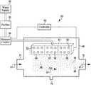
- FIG. 1is a diagram of an illustrative example of humidifying system 55 .
- Arrays 56 , 57 and 58may contain spray units 59 .
- Watermay be fed to a manifold device 61 that distributes the water to spray units 59 .
- the watermay come from a supply 62 . If the water is not truly clean, like distilled water, the water may go to a purifier 63 for cleansing.
- Purifier 63may use, for example, reverse osmosis for obtaining clean water from ordinary water, such as tap or faucet water from a well or city supply.
- the wateris controlled relative to pressure with a pressure control module 64 .
- the watermay flow from pressure control 64 to a unit 61 via a water conveyance line or pipe 65 to distribution or manifold device 61 .
- the watermay be provided to the spray units of array 56 , 57 and 58 .
- Pressure control unit 64may have an input from a controller 60 that indicates an amount of pressure for the water in pipe 65 to the spray units 59 .
- a pressuremay be 2.5 inches of water from a top of a reservoir under atmospheric conditions to a spray unit 59 .
- a line 66 from controller 60may provide an actuation signal to spray units 59 , which actuates or turns on one or more of spray units 59 .
- Spray units 59may be turned on separately according to array.
- Array 56 , of spray units 59may be on for a given period of time or have a duty cycle while the other arrays 57 and 58 are turned off or inactive.
- Arrays 57 and 58 of spray units 59may, in turn, be actuated while the other two arrays are turned off or inactive.
- the spray unitsmay be actuated individually, in a pattern, or a sequence, of various kinds.
- Arrays 56 , 57 and 58may be removed and cleaned, repaired or replaced, as needed. There may be more or less than three arrays and there may be more or less than six spray units in each array.
- System 55may be placed in an enclosure 66 where water droplets 68 from spray units 59 are mixed in with air 67 , from duct 71 , moving past spray units 59 .
- Droplets 68may be small enough such that the droplets 68 result in a vapor that moves with air 67 through enclosure 66 and to an air return duct 72 .
- Spray units 59may eject water droplets 68 up, down or sideways relative to enclosure 66 .
- the droplets 68may be ejected perpendicular, parallel or at other angles relative to a flow of air 67 .
- Duct 71may be the warmer and/or higher pressure duct in comparison to air return duct 72 , which would accommodate vaporization of droplets 68 and movement of air 67 from duct 71 to duct 72 .
- the designmay also work with reverse airflow configurations to accommodate installations where the bypass humidifier was installed on the high pressure duct, with the bypass attached to the low pressure, resulting in backwards airflow.
- Enclosure 66may also incorporate one or more components of pressure control 64 , controller 60 , purifier 63 , and other items as desired.
- Enclosure 66 and its componentsmay replace current humidifier systems in present HVAC systems in homes and buildings in a very easy manner.
- Enclosure 66may be designed to fit in as a replacement having the same size duct connections, mounting fasteners, water, electrical connections, and more as desired.
- a tool-like clamp designmay be used to attach enclosure 66 to an existing opening in existing ducts.
- a strap that wraps around an existing humidifier enclosure or bodymay be used to secure the new present humidifying system 55 to the ducts.
- the present systemmay replace a conventional system or a portion of elements of the existing system such as a cover and/or air hydration elements like evaporative pads and frames or steam generating elements, but retain the existing or conventional enclosure.
- Spray units 59 or emittersmay be monitored with associated detectors, or other ways, so as to provide a notification that an array containing a poor spray unit should be removed, repaired or replaced.
- the water for the spray units 59may be monitored to provide a notification in the event that purifier 63 is not working at or near optimal performance, and that repair or replacement is needed, such as, e.g., a reverse osmosis filter.
- Enclosure 66may be designed to recapture droplets 68 that have not evaporated and drain them via a drain 73 to prevent their entry to low pressure or return duct 72 .
- Flow of air 67may be circulated in a cyclonic vortex so that water droplets 68 are displayed in a way, such as through a clear window on enclosure 66 or other disclosure, that lets one witness water being put into air 67 and to keep droplets from attaching to surfaces near spray unit 59 .
- the vortex approachmay offer an effectively extended evaporation distance that can help increase the amount of evaporation that occurs.
- the vortexmay serve as a cyclonic separator that can drive any large droplets that might occur on the sidewalls and let them drain away in a controlled way instead of injecting them into the air duct.
- the arrays of spray units 59may be grouped in a manner that the arrays can be enabled selectively, so that for any time interval, only one array is enabled, and after a number of time intervals equal to, for instance, the number of arrays, each spray unit in the respective array will have to be operating for the same length of time as each of the other arrays.
- a purpose for rotating which spray units are enabledmay be to extend the operating life of an entire array by reducing the duty cycle for each spray unit. Visual observation through a window of enclosure 66 may aid in determining satisfactory operation of each spray unit 59 .
- Purifier 63such as an RO filtration component, may be within the same enclosure 66 as spray units 59 and drain 73 , in that, for instance, seal failure may result in leaked water being directed to drain 73 .
- a power supply and logic board of controller 60may power multiple spray units 59 individually, or in groups, to provide desired functions of spray units 59 .
- Air temperature and humiditymay be measured in a plenum just downstream of an associated furnace and AC unit for diagnosis so as to provide proper sizing and health of the furnace and AC unit, for example, to avoid too low temperature of heated air or too high temperature of cooled air.
- Humidifying system 55may be connected such that operation and sensor status may be conveyed to an outside computing device.
- System 55may be connected such that a computing device on-board, such as controller 60 , can be remotely controlled by another computing device, by recalling in a resident memory of any type.
- System 55may be connected to the internet to gather data, alert an owner about maintenance or an HVAC system issue, or other item of concern or interest, particularly relative to system 55 .
- Spray units 59 of system 55may be arranged in various configurations other than that revealed in FIG. 1 .
- FIGS. 2 a -2 dare diagrams of spray units 59 in various circular fashions.
- Spray units 59may be arranged in a square, triangular, oval, rectangular, and other geometrical forms.
- Spray units 59may be oriented to emit droplets up, down, sideways, and at various other angles, or in a combination of different directions.
- the geometrical forms for placing spray units 59may be two-dimensional or three dimensional.
- Spray units 59may be arranged in a three-dimensional manner which may provide certain desired effects of a respective spray unit arrangement.
- FIG. 2 ais a diagram of a round plate layout 75 of spray units 59 on a manifold-like interface 76 with a tube or conveyance mechanism 77 for providing fluid to spray units 59 .
- FIG. 2 bis a diagram of a thick plate layout 81 with spray units 59 on the plate surface and spray units on the surface of a thick edge of the plate. A center of the plate and its spray units might be absent leaving a ring-like structure having just the thick edge with spray units 59 . Such configuration may be referred to a dog-collar.
- FIG. 2 cis a diagram of a drum layout 82 having multiple rows of spray units 59 on the side surface of the drum. The bottom or the top surface may have spray units 59 .
- FIG. 2 dis a diagram of a layout 83 like that of layout 75 of FIG. 2 a , but being oriented with spray units 59 at an angle, either up or down, or other ways.
- Spray units 59may be selected from a variety of devices such as nozzle injectors, atomizers, nebulizers, and so forth.
- example nebulizersmay be noted.
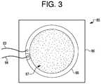
- FIG. 3is a diagram of nebulizer 85 .
- Nebulizer 85may be a stainless steel plate 86 having about 600 to 800 holes 87 . Each hole 87 may have a diameter of five to seven microns. Other variations of nebulizer 85 may have 50 to 5000 holes in plate 86 , having a diameter between 0.5 and 50 microns.
- a piezoelectric ring 88may be attached to steel plate 86 encircling holes 87 in plate 86 . Plate 86 may be made from other materials.
- Piezoelectric ring 88may actuate plate 86 with an AC current applied to leads 93 and 94 . Other kinds of mechanisms may be used to actuate plate 86 .
- a shape of the nebulizer 85 layout of holes 87 and piezoelectric ring 88may each have a shape other than shown in the diagram of FIG. 3 .
- About twenty nebulizers 85 as described in FIG. 3 used as spray units 59 in system 55may use, as an estimate, about twelve gallons of purified water per day. An amount of water used may vary, particularly in accordance with a design for system 55 , associated HVAC, and nebulizers 85 .
- Plate 86may have a thickness of about 0.5 mm. Holes 87 may be made within a circle of about 6.5 mm in diameter. Ring 88 of piezoelectric material may be glued to a surface of plate 86 so that holes 87 are within an inner diameter of ring 88 . As an AC current or voltage is applied to ring 88 , the piezoelectric material of ring 88 may shrink and expand radially. The shrinking may make metal plate 86 buckle and thus eject droplets of fluid (e.g., water).
- fluide.g., water
- Nebulizers 85may be operated with plates 86 in resonance in order to increase movement of plates 86 , output and efficiency of the nebulizers.
- a steady flow of fluide.g., water
- nebulizers 85for instance, in a humidifier, there may be a decrease in fluid flow due to a change of resonant frequency of nebulizers 85 , for example, due to a load or stiffness change of vibrating plates 86 , such as some material being deposited or removed from plates 86 or holes 87 .
- Deposited materialsmay consist of minerals or other materials or particles, including organics, that are in the water. If each plate 86 is coated with a special film, e.g., hydrophobic or hydrophilic, the material deposited on plate 86 , material on plate 86 may be washed out during operation of respective nebulizer 85 .
- More than one nebulizermay be on a plate.
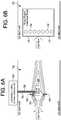
- FIG. 4 a and FIG. 4 bare diagrams 91 and 92 , respectively, that appear to show an impact of washing nebulizers 85 in soapy water on the resonant frequency of a plate 86 .
- a nebulizer resonant frequency in diagram 92may indicate a shift in resonant frequency from an original 100 kHz to about 104 kHz. The shift may be attributed to an ultrasound washing with soapy water that removed some mass from plate 86 and increased the resonant frequency.
- An opposite frequency shiftmay be caused by a material deposition during operation of nebulizers 85 as spray units 59 during operation in a humidifier system 55 having a purifier 63 that uses an RO filter which cleans out, perhaps, just 95 percent of the minerals of the water conveyed by nebulizers 85 .
- Diagram 91is a graph of plots of frequency of plate 85 in kHz relative to drive current in milliamps. Curves # 1 through # 6 are plotted in diagram 91 and are listed in diagram 92 indicating the various nebulizer flows for 100 kHz and 104 kHz, respectively, as indicated by the legend in FIG. 4 a . From the plot in FIG.
- FIG. 5is a diagram of a drive circuit 95 , which may be modified to adjust the frequency to a maximum current consumption, and may be an optimization of current for a nebulizer or a 30 group of nebulizers.
- Drive circuit 95may maximize flow by maximizing current. So the nebulizer may be actuated to operate close to or at the resonant frequency.
- Frequency tuningmay be achieved by measuring current magnitude at lead 93 or 94 of piezoelectric ring or element 88 , that makes the mesh plate vibrate. The current may be the largest in magnitude during resonance since most of the water is pushed out by plate 86 as it moves by the largest amount. Pushing out more water may require more energy than is provided by the electric current.
- frequency optimizationmay be achieved by changing the frequency of the drive current to piezoelectric element 88 reaches a maximum amount of drive current.
- Current measurements and frequency adjustmentsmay be done for an individual device or for groups of devices to avoid costs of additional electrical components.
- the approach for a group of nebulizersis feasible if all nebulizers in the group have the same mass addition or removal.
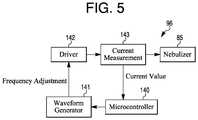
- FIG. 5is a diagram of a driver circuit 96 , which may be a part of controller 60 in FIG. 1 .
- a microcontroller 140may provide a signal to a waveform generator 141 , which may output an AC signal having a frequency that is adjustable according to a signal from microcontroller 140 .
- the AC signalmay go to a driver 142 .
- Driver 142may provide the signal from generator 141 with sufficient current to drive piezoelectric ring 88 ( FIG. 3 ).
- Measuring circuit 143can provide a current magnitude measurement to microcontroller 140 , which may vary the signal to waveform generator 141 that adjusts the frequency so that the current magnitude achieves a maximum.
- nebulizer 85may go to a nebulizer 85 or an array of nebulizers 85 via leads 93 and 94 to piezoelectric ring 88 of the one or more nebulizers 85 .
- Microcontroller 140 , waveform generator 141 , driver 142 and current measuring circuit 143may constitute a servo loop of circuit 96 for self-calibration and maximizing the current of the drive signals for maximizing flow by nebulizer or nebulizers 85 .
- Circuit 96may ensure automatic adjustment of the nebulizer drive frequency to be at resonance in spite of drift of the resonant frequency of nebulizer 85 over time.
- nebulizers 85that may be used as spray units 59 , some issues might appear apparent. Running nebulizers dry in periods of long activity to prevent an appearance of pathogens in standing water, a dry state may be detected by observing a higher current in each nebulizer. Nebulizers should not be left to run dry for long periods of time.
- Determining leakage in system 55may be done by measuring a water flow rate that exceeds the nebulizer flow rate. Each nebulizer 85 flow may be characterized periodically so that a correct amount of water is delivered to air to avoid condensation.
- a design of a nebulizer and a wing to provide or improve a laminar air flowmay be one way to optimize droplet mixing with air and ensuing evaporation.
- a humidifierthat injects small water droplets in an air stream or flow may cause droplet accumulation on nearby surfaces if the air flow is turbulent. Accumulated water may drip down and form a puddle that can cause water damage and encourage a growth of algae, bacteria or mold.
- An example of such a humidifiermay be a nozzle injection system or a nebulizer system.
- Nebulizer plates 86may be a way of generating small droplets 68 .
- the nozzle or hole 87 size in plates 86should be very uniform because even a few micro holes with a larger diameter than holes 87 may result in a big quantity of large droplets.
- the large dropletsmay also form from collisions between small droplets. Large droplets may take a long time to evaporate and during that time can hit and accumulate on return air duct structure 72 ( FIG. 1 ).
- the dropletsshould be very small, e.g., 5-7 microns, so as to evaporate before they have many chances of collision or create a deposition of water on air duct 72 features like corners or walls.
- the large droplets that follow a straight path due to their larger momentummay be hit by small droplets that follow a slightly turbulent direction. This activity may generate even larger droplets.
- the small dropletsmay be injected in a laminar air flow so that they follow parallel paths and have a lower probability of colliding and creating large droplets.
- Laminar air flowmay be obtained with a special shape of a nebulizer head 151 as shown in diagrams of FIG. 6 a and FIG. 6 b .
- the nebulizer head 151may have a shape of a rectangular wing that is attached in the middle of an air duct 152 .
- Arrays 153 of nebulizersmay be situated at a leading edge of head 151 on the bottom and top of head 151 .
- Electronics, a valve and filter e.g., RO,may be in a box 154 with a water line 155 and electrical drive 156 connected to nebulizer arrays 153 .
- the diagram of FIG. 6 ashows a side view of wing shaped nebulizer head 151
- the diagram of FIG. 6 bshows a bottom view of the wing shaped nebulizer head 151 .
- a level sensor 164may be placed at nebulizer head 151 .
- An edge of an opening holding nebulizer array 153 , or plate 86 ( FIG. 3 ) on nebulizer head 151may cause turbulence that could be removed with a water proof gasket 162 by attaching nebulizer array 153 with double-sided sticky tape 161 or gluing array 153 to an outside wall of nozzle head 151 shown in a diagram of FIG. 7 .
- Such configurationmay remove surface features that produce air flow eddies, and provide for an entrainment of droplets in the air flow or stream without collisions.
- the nozzlesmay also be placed on a top surface of nebulizer head 151 as in a diagram of FIG. 8 , and water may be delivered to the nozzles by filling a container or providing a wick.
- Nebulizer head 151may be manufactured with 3 D printing. Double sticky tape 161 with a thin layer of foam may be recommended to allow for vibration of nebulizer array 153 plate 86 , as it may be a vibration force that ejects droplets 68 ( FIG. 1 ).
- the rest of a systemmay consist of a water purifier, e.g., reverse osmosis, a nebulizer drive and controller that turns the nozzle plates 86 on and off, and maintains a water level in head 151 .
- a nebulizermay be damaged if it operates without water. On the other hand, leakage may develop if the water level for the nebulizer gets too high.
- the water levelmay be sensed by a level detector, e.g., a conductivity based detector.
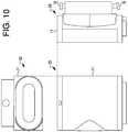
- FIG. 9is a diagram of enclosure 11 for a humidifier arrangement that incorporates an emitter or nebulizer array 12 that provides droplets 13 of water into an air 14 that flows sideways from duct 15 through a volume 16 where the air 14 interacts with droplets 13 to become misty air 17 that flows down toward the bottom of enclosure 11 and out of the enclosure through a cold air return duct 18 .
- the term “down”may mean toward the earth's surface.
- the term “up”may mean away from the surface of the earth.
- a clear window 19may be part of enclosure 11 that might permit one to see the misty air 17 flowing through enclosure 11 .
- a drainmay be at the bottom of enclosure 11 for removal of water from the enclosure.
- Items 21may be magnetic plugs that aid in connecting enclosure 11 to ducts 15 and 18 .
- FIG. 10is a diagram that reveals a top view 22 , a front view 23 and a right or side view 24 of enclosure 11 .
- Enclosure 11may be regarded as a pill type enclosure.
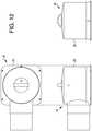
- FIG. 11is a diagram of an enclosure 25 for a humidifier arrangement that incorporates an emitter nebulizer array 26 that provide droplets 27 of water downward into an upward flow of air 28 from a duct 31 to a center portion of enclosure 25 and become an air and mist mixture or misty air 29 that moves downward toward a bottom of enclosure 25 into a cold air return duct 32 .
- FIG. 12is a diagram that reveals a front view 33 , a bottom view 34 and a side or right view 35 of enclosure 25 .
- Enclosure 25may be oriented in different positions where the droplets 26 are emitted sideways and that the mist and air 29 move sideways into duct 32 .
- Enclosure 25may be regarded as a round type enclosure.
- FIG. 13is a diagram of an enclosure 38 for a humidifier arrangement that incorporates an emitter or nebulizer array 39 that provides droplets 41 of water upward into an incoming air flow 42 from an entrance or duct 43 . Droplets 41 may move upward from array 39 along with air 42 and mix into a mist and air 43 to move upward in a center tube 44 and then downward in an outer concentric tube 45 and then upward at an inside volume of wall 47 of enclosure 38 to a cold air return duct 48 .
- FIG. 14is a diagram that reveals a top view 51 , a front view 52 , and a side or right view 53 of enclosure 38 .
- Enclosure 38may be regarded as a cyclone type of enclosure.
- FIG. 15is a diagram of a model “A” humidifier enclosure 245 .
- Enclosure 245may have a lower housing 246 and an upper housing 247 .
- FIG. 16is a diagram of enclosure 245 without front shell 252 thereby revealing some internal components in enclosure 245 .
- Emitter housing 251may contain an emitter arrangement and an LED.
- An air guide 254 and an air output port 255are shown.
- FIG. 17is a diagram revealing an air flow 257 through enclosure 245 .
- Dry airmay enter air intake port 249 , go past the emitter in housing 251 where micro water droplets 258 are released by the emitter into the dry air of air flow 257 where the air becomes humid and flows through lower housing 246 , around air guide 254 into upper housing 247 , and through output port 255 as humid air.
- Air flow 257may follow a path that is of an extended nature for a given size of enclosure 245 to ensure evaporation of droplets 258 before reaching output port 255 .
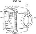
- FIG. 18is a diagram of a back view of enclosure 245 .
- Air intake port 249may have a pipe placement or attachment component.
- Enclosure 245may be attached to the existing bracket 248 with output 255 for humidified air moving into a return air duct.
- Pegs 261may secure enclosure 245 to existing bracket 248 .
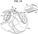
- FIG. 19is a diagram showing emitter housing 251 with emitters 262 and one or more LEDs 263 .
- Housing 251may fit into a cavity 264 of enclosure 245 .
- Emitters 262may eject micro droplets 258 into dry air coming through air intake port 249 .
- the approachmay incorporate determining a temperature in a space associated with a humidifying unit, determining a relative humidity in the space, determining an air speed associated with the humidifying unit, and adjusting an amount of water sprayed by the humidifying unit based, at least in part, on the temperature, the relative humidity, and the air speed.
- a humidifying devicemay be modular and scaled for use in small spaces (e.g., vehicles, residences, or the like) and/or large spaces (e.g., large residences, commercial buildings, and the like) as well as spaces in between.
- Humidifying devices in accordance with the present disclosuremay be used in spaces designated for specialized commercial operations, such as internet server centers and/or clean rooms (e.g., spaces for integrated circuit fabrication).
- Items of the present disclosuremay be modular, such as those that are easier to control, more efficient, and/or more reliable than previous approaches.
- spray unitse.g., spray heads
- an arrayfor instance (e.g., as part of a humidifying device or unit (hereinafter referred to as a “humidifier”)).
- Each spray unit of the arraymay be controlled and/or operated (e.g., turned on and/or off) independently. Independent operation may be performed using a respective control component (e.g., an actuator and/or electric switch) associated with each spray unit.
- a respective control componente.g., an actuator and/or electric switch
- each spray unitBy operating the spray units independently of each other, one may allow each spray unit to be used for a reduced period of time and/or at intervals with respect to previous approaches. Independent operation may increase a lifetime of each individual spray unit, for instance, as well as a humidifier incorporating the array of spray heads.
- spraying units in the humidifiermay allow for a gradual degradation of humidifier performance rather than abrupt degradation and/or failure as with previous approaches. For example, a humidifier having twelve spray heads where one has failed may be just minimally reduced in performance versus a humidifier having a single spray head that fails. Thus, a useful life of the humidifier may be extended in instances where some of the spray heads experience failure(s).
- independent operation of spray unitsmay allow for rotation of active spray units. That is, some embodiments may allow cycling of activated (e.g., turned-on and/or spraying) spray units. For example, a first subset of the array of spray units (e.g., a first nozzle plate) may be operated for a period of time (e.g., 1-2 minutes) and then a second subset of the array of spray units (e.g., a second nozzle plate) may be operated for another period of time (e.g., 1-2 minutes) while the first subset is deactivated. Thereafter, the first subset may be reactivated and/or a third subset (or more subsets) may be activated similarly. Using independent operational control of the spray units may also allow the activation and deactivation of spray units within a single nozzle plate.
- activatede.g., turned-on and/or spraying
- Condensation problems associated with some approachesmay be reduced (e.g., eliminated) because by rotating activated spray units, the present approach may avoid cooling portions of a humidifier (e.g., nozzle plate fixtures) to a degree such that water vapor condenses thereon. By reducing condensation, the present approach may increase efficiency associated with operation of a humidifier and reduce (e.g., eliminate) contamination of air ducts with water, for instance. Durations of activity and/or inactivity of spray units may be determined based on one or more factors. For instance, rotation frequency may be increased based on increased level(s) of humidity.
- Rotation frequencymay be decreased based on decreased fan speed(s) and/or temperature(s).
- rotationmay incorporate a first subset of plurality of spray units being activated for a particular period of time. Then, the rotation may incorporate a second subset of the plurality of spray units being activated and the first subset of the plurality of spray units being deactivated for the particular period of time.
- the subsetsmay be determined based on their location. For example, the firsts subset may be located on a first side of the humidifier and the second subset may be located on a second (e.g., opposing) side of the humidifier. Reducing condensation by rotating spray units may reduce humidifier deterioration caused by prolonged presence of moisture (e.g., on dry side of humidifier), for instance.
- coatings with super-hydrophobic propertiesmay also provide a way to mitigate the condensation, or accumulation of water by preventing it from accumulating at all.
- Super-hydrophobic coatingsmay be applied to surfaces within the system which have a high likelihood of accumulating water droplets, or are susceptible to problems such as growth of biological contaminants, accumulation of water-borne materials, corrosion, rot, discoloration or pooling.
- Modular designs in accordance with the present systemare not necessarily limited to a particular configuration. Rather, such designs may be customized according to duct access, orientation (e.g., vertical or horizontal) and/or size.
- the present approach and systemmay incorporate vertical configurations of one or more arrays of spray units and/or horizontal configurations of one or more arrays of spray units (e.g., using narrow trays and a nozzle plate or plates inserted in a middle of a duct).
- the present approach and systemmay provide humidification in conjunction with cooling more efficiently than some other approaches.
- standard cooling heat exchange coilsmay extract humidity from air due to condensation on cold surfaces. Because the condensation may release heat, air conditioning units might need to compensate and thus consume more electricity.
- an additional humidifying devicee.g., an evaporator
- an evaporatormay be employed to replenish it.
- such devicesmay generate heat and thus utilize more electricity.
- energymay be expended twice—first to condensate water from vapor, and then to evaporate water.
- the present systemmay reduce electricity usage by providing humidification and cooling in a single device.
- the systemmay allow a regulation of water dispersed (e.g., sprayed) by a humidifier such that the water (e.g., virtually all the water) evaporates rather than condenses on surfaces of ducts.
- a humidifiersuch that the water (e.g., virtually all the water) evaporates rather than condenses on surfaces of ducts.
- Such systemmay be based on a principle that the evaporation speed of a water droplet is proportional to the diameter of the droplet squared and inversely proportional to a difference between the dry and wet bulb temperatures.
- a time of flight of a droplet before it reaches a surface on which it may be depositedmay also be inversely proportional to the speed of the air carrying it. That speed, for instance, may be controlled and/or determined by the speed (e.g., setting) of a fan in forced air conditioning systems. Accordingly, embodiments of the present system may finely control an amount of water used by a humidifier to achieve desired cooling and/or humidification while reducing condensation based, at least in part, on air temperature, humidity, and air speed.
- a number of spray unitsmay refer to one or more spray units.
- An array of nebulizersmay be configured to expel air to prevent the degradation of array performance from trapped air.
- the expulsion of water dropletsalso has the possibility of ingesting air bubbles, which can accumulate near or against the water source facing surface of the nebulizer, causing an interruption in normal operation.
- the systemmay use one or more mechanisms to regulate water pressure within the system to prevent over-pressurization which can lead to nebulizers “sweating” when not operating.
- a reservoirmay be used within the system to hold water at a depth which cannot exceed that which causes water pressure to exceed the maximum supported by the nebulizer.
- the systemmay incorporate several visual elements to give human operators feedback as to the operational health of the system.
- the Systemmay incorporate LED illumination to make the mist more visible to an observer, and also incorporate transparent viewing elements into the design to further enable the observation of water mist.
- the systemmay incorporate a user input button which can allow the unit to begin operating regardless of the normal operating stats it is in.
- This functionis designed to show an operator that the unit is functioning properly, even if the related systems that control it (i.e.: the furnace and/or humidistat) are not presently telling the unit to operate.
- activating the featuremay cause the unit to begin operating, as if under normal operating conditions to allow for the creation of water mist by the nebulizer array, and illumination to be turned on, so that an observer can see that plumbing has been installed properly, and the system has power needed to function.
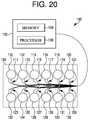
- FIG. 20is a diagram of a system 100 for humidifying.
- System 100may incorporate a control unit 102 communicatively coupled to a humidifying unit 108 .
- Control unit 102may, for example, be a computing device having a memory 104 (e.g., storing a set of executable instructions) and a processor 106 (e.g., configured to execute the executable instructions), though various versions of the present system are not necessarily limited.
- control unit 102may incorporate an integrated circuit and/or logic to perform a number of the functionalities described herein.
- Control unit 102may incorporate a memory 104 and a processor 106 .
- Memory 104may be any type of storage medium that can be accessed by processor 106 to perform various examples of the present disclosure.
- memory 104may be a non-transitory computer readable medium having computer readable instructions (e.g., computer program instructions) stored thereon that are executable by processor 106 for humidifying in accordance with one or more embodiments of the present disclosure.
- Memory 104may be volatile or nonvolatile memory. Memory 104 may also be removable (e.g., portable) memory, or non-removable (e.g., internal) memory.
- memory 104may be random access memory (RAM) (e.g., dynamic random access memory (DRAM) and/or phase change random access memory (PCRAM)), read-only memory (ROM) (e.g., electrically erasable programmable read-only memory (EEPROM) and/or compact-disc read-only memory (CD-ROM)), flash memory, a laser disc, a digital versatile disc (DVD) or other optical disk storage, and/or a magnetic medium such as magnetic cassettes, tapes, or disks, among other types of memory.
- RAMrandom access memory
- DRAMdynamic random access memory
- PCRAMphase change random access memory
- ROMread-only memory
- EEPROMelectrically erasable programmable read-only memory
- CD-ROMcompact-disc read-only memory
- flash memorya laser disc, a digital
- memory 104may be illustrated as being located in control unit 102 , embodiments of the present disclosure are not necessarily so limited.
- memory 104may also be located internal to another computing resource (e.g., enabling computer readable instructions to be downloaded over the Internet or another wired or wireless connection).
- Humidifying unit 108may incorporate a plurality (e.g., array) of spray units. As shown in FIG. 20 humidifying unit 108 may incorporate a spray unit 110 , a spray unit 112 , a spray unit 114 , a spray unit 116 , a spray unit 118 , a spray unit 120 , a spray unit 122 , a spray unit 124 , a spray unit 126 , a spray unit 128 , a spray unit 130 , and a spray unit 132 (sometimes generally herein referred to as “spray units 110 - 132 ”). Although 12 spray units may be illustrated in the example shown in FIG. 20 , embodiments of the present disclosure are not necessarily limited to a particular number of spray units.
- each of spray units 110 - 132may be connected (e.g., communicatively coupled) to control unit 102 by a respective pair of wires.
- Spray unit 110may be connected via wires 111
- spray unit 112may be connected via wires 113
- spray unit 114may be connected via wires 115
- spray unit 116may be connected via wires 117
- spray unit 118may be connected via wires 119
- spray unit 120may be connected via wires 121
- spray unit 122may be connected via wires 123
- spray unit 124may be connected via wires 125
- spray unit 126may be connected via wires 127
- spray unit 128may be connected via wires 129
- spray unit 130may be connected via wires 131
- spray unit 132may be connected via wires 133 (the wires illustrated in FIG. 20 may sometimes be cumulatively referred to herein as “wires 111 - 133 ”).
- control unit 102may communicate with and/or control an operation of (e.g., activate and/or deactivate) each of spray units 110 - 132 independently (e.g., individually).
- Each of spray units 110 - 132may incorporate a spray nozzle.
- each of spray units 110 - 132may incorporate an ultrasonic atomizer and/or nebulizer having a piezoelectric element (e.g., ceramic, crystal, and so forth) attached to a metal plate with an array of small openings (e.g., holes), for instance (e.g., 5 microns in diameter).
- voltage applied across the piezoelectric elementmay cause the element to vibrate and expel water droplets through the openings (e.g., a fine mist of water).
- the present systemis not necessarily limited to a particular type of spray unit and may incorporate various devices configured to disperse water (e.g., fine water droplets) into air.
- the system illustrated in FIG. 20may allow for the minimization of condensation upon any portion of humidifying unit 108 . Because condensation may release heat, air conditioning units may use increased energy to maintain cool temperature levels in some other approaches.
- the present systemmay regulate a length of activation time and/or an amount of water sprayed by one or more spray units of a humidifying unit such that the sprayed water is evaporated rather than condensed. Reducing condensation may incorporate, for instance, rotating one or more spray units.
- FIG. 21is a diagram of a system 236 for humidifying.
- System 236may, for example, combine a cooling system (e.g., an air conditioner) with a humidification system (e.g., a humidifier).
- System 236may make use of a principle that a rate of water droplet evaporation is proportional to a diameter of the water droplet squared and inversely proportional to a difference between a dry bulb temperature and a wet bulb temperature.
- Another principle usedmay be that a time of flight (e.g., through a duct) of water droplets before they reach a surface on which they may be deposited is inversely proportional to a velocity of the air (e.g., the fan speed setting in a forced air conditioning system).
- a target (e.g., desired) cooling and/or humidification ratemay be controlled by varying an amount of water released by the humidifier.
- a target cooling and/or humidification ratemay be controlled by varying an air speed passing (e.g., passing by, over, under, across, and so on) a humidifier.
- the air speedmay be proportional and/or related to a speed (e.g., speed setting) of a fan of an HVAC system associated with the space.
- System 236may incorporate a humidifier 200 (e.g., a humidifier analogous to system 100 ( FIG. 20 ) and a sensor unit 240 inside an air duct 238 (illustrated as a cross-section of a portion of a duct in FIG. 21 ).
- Sensor unit 240may be located a particular distance 242 , in a direction of air flowing through the duct, from humidifier 200 .
- system 236may incorporate a fan.
- the fanmay be in communication with a control unit (e.g., control unit 102 of FIG. 20 ) through a wired and/or wireless connection.
- the fanmay have a fixed speed, or the fan may have a number of discrete speed settings. Or fan speed may be continuously adjustable over a range of speeds. There may be an adjusting a speed of a fan (e.g., to provide desire cooling and/or air flow).
- Sensor unit 240may incorporate a number of sensors. Although sensor unit 240 is illustrated as a single component, various adaptations sensor unit 240 may be in accordance with the present system. For example, sensor unit 240 may incorporate one or more temperature sensors. Temperature sensors may be configured to determine (detect, measure, and/or acquire) dry bulb temperature(s) inside duct 238 .
- sensor unit 240may incorporate one or more relative humidity sensors.
- the wet bulb temperaturemay be inferred from humidity and temperature measurements using a known relationship (e.g., dependence), which may be represented in a table and/or equation, for instance.
- a known relationshipe.g., dependence
- sensor unit 240may incorporate any number and/or type of sensor configured to determine various parameters associated with the air flowing through duct 238 .
- System 236may incorporate an upstream sensor unit 241 .
- Upstream sensor unit 214may incorporate one or more temperature sensors and/or relative humidity sensors in a manner analogous to sensor unit 240 , for instance.
- Upstream sensor unit 241may be in communication with a control unit (e.g., control unit 102 , noted in connection with FIG. 20 ) through a wired and/or wireless connection, for instance.
- Upstream sensor unit 241may be used in conjunction with sensor unit 240 to determine change(s) in temperature and/or humidity caused by humidifier 200 . Locating upstream sensor 241 immediately upstream from humidifier 200 may allow embodiments of the present disclosure to moderate and/or finely tune one or more operations of humidifier 200 .
- humidifier 200may disperse water droplets which can be carried through the air along distance 242 .
- Distance 242may be determined and/or selected such that the water droplets released from humidifier 200 have sufficient time to evaporate (e.g., sufficient time for humidity mixing in the air) before reaching sensor unit 240 , for instance.
- Measurements associated with the flowing (e.g., flowing and humidified) airmay be taken by sensor unit 240 and used by embodiments of the present disclosure to vary an amount of water released by humidifier 200 , for instance, in controlling and/or maintaining a target cooling and/or humidification rate.
- the present systemmay incorporate maintaining relative humidity within a particular humidity range. That is, it may maintain relative humidity below a first threshold and above a second threshold.
- a control unitmay be configured to receive an indication of the relative humidity and an indication of the temperature and cause a modification of an operation of the humidifying unit in response to at least one of the relative humidity and the temperature exceeding a particular threshold.
- Increased temperature differencesmay be used in the system having larger droplets (e.g., if droplet diameter increases by a factor of 1.41, temperature difference may increase two-fold).
- Droplet sizemay be kept constant by maintaining parameters of spray units (e.g., nozzles). For example, droplet size may be kept constant by keeping the spray unit frequency and/or actuation voltage under a threshold at which the droplets may tend to merge into a continuous stream of water.
- spray unitse.g., nozzles
- the present systemmay adjust a number of spray units that are activated and/or deactivated.
- the activation and/or deactivationmay be responsive to a temperature exceeding a particular threshold.
- a threshold temperaturemay be established (e.g., 16 degrees Celsius and/or 8 degrees Celsius below a set point of a thermostat associated with humidifier 200 ). Then, if a temperature determined by sensor unit 240 increases above the threshold temperature and a relative humidity determined by sensor unit 240 decreases below the curve, a spray unit (e.g., spray unit 122 ) may be activated.
- the threshold temperaturemay be higher (e.g., 20 degrees Celsius and/or 2 degrees Celsius below the thermostat set point), so the cooling may not be as pronounced as previously discussed, but humidification may still be occurring.
- the present systemmay reduce (e.g., prevent) condensation by ensuring that water droplets are evaporated (rather than condensed).
- the present systemmay deactivate humidifier 200 if relative humidity is determined by sensor unit 240 to exceed a particular threshold (e.g., 35%).
- a particular thresholde.g., 35%).
- air conditioninge.g., traditional air conditioning
- the present systemmay accordingly cause a modification of an operation of the humidifying unit in response to the relative humidity exceeding a particular threshold and/or the temperature exceeding a particular threshold.
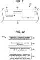
- FIG. 22is a diagram of an approach 344 for humidifying in accordance with the present system.
- Approach 344may be performed by a control unit (e.g., control unit 102 ( FIG. 20 ), for instance.
- the control unitmay, for example, be a computing device, but not necessarily so limited.
- the control unitmay incorporate an integrated circuit and/or logic.
- approach 344may incorporate determining a temperature in a space associated with a humidifying unit.
- a temperaturemay be determined in a duct associated with a humidifying unit. That is, approach 344 may incorporate determining a temperature in a duct at a particular distance downstream from the humidifying unit.
- a temperaturemay be determined at other locations.
- a space associated with a humidifying unitmay contain a thermostat. The thermostat may determine a temperature at its location in the space, for example. The thermostat may be in communication with the control unit through a wired and/or wireless connection, for instance. However, a temperature may be determined at additional or other locations within the space.
- approach 344may incorporate determining a relative humidity in the space.
- a relative humiditymay be determined in a duct associated with a humidifying unit. That is, approach 344 may incorporate determining a downstream relative humidity in a duct at the particular distance downstream from the humidifying unit.
- a relative humiditymay be determined at other locations.
- a space associated with a humidifying unitmay contain a thermostat.
- the thermostatmay determine a relative humidity at its location in the space, for example.
- the thermostatmay be in communication with the control unit through a wired and/or wireless connection, for instance.
- a relative humiditymay be determined at additional or other locations within the space.
- approach 344incorporate determining an air speed associated with the humidifying unit.
- An air speedmay be a speed of air passing (e.g., passing by, over, under, across, or otherwise) the humidifying unit.
- the air speedmay be proportional and/or related to a speed (e.g., speed setting) of a fan of an HVAC system associated with the space.
- determining the air speedmay incorporate determining the fan speed.
- a relationship between fan speed and air speedmay allow the determination of air speed based on fan speed. It may be understood that such a relationship may vary depending on the particular installation and may be determined (e.g., calibrated), for instance, at the time of installation.
- the fanmay be in communication with the control unit through a wired and/or wireless connection.
- a fanmay have a fixed speed.
- a fanmay have a number of discrete speed settings.
- a fan speedmay be continuously adjustable over a range of speeds.
- a fane.g., a fan speed associated with the humidifying unit may be adjusted (e.g., to provide desired cooling, humidity, and/or air flow).
- approach 344may incorporate adjusting an amount of water sprayed by the humidifying unit based on the temperature, the relative humidity, and the air speed. Adjusting an amount of water sprayed by the humidifying unit may incorporate activating and/or deactivating a portion of the humidifying unit (e.g., a number of spray units of the humidifying unit).
- Adjustingmay incorporate cycling of activated (e.g., turned-on and/or spraying) spray units. Individual spray units may be controlled independently. The amount of water sprayed may be adjusted based on a desired humidity level in the space associated with the humidifying unit.
- activatede.g., turned-on and/or spraying
- Approach 344may incorporate determining an upstream relative humidity in a duct upstream from the humidifying unit.
- the upstream relative humiditymay be determined using an upstream sensor unit (e.g., upstream sensor unit 214 ), which may incorporate one or more temperature sensors and/or relative humidity sensors. Determining the upstream relative humidity may allow the determination of change(s) in temperature and/or humidity caused by the humidifier and/or the fine tuning of one or more operations of the humidifier.
- Embodiments of the present disclosurecould be used as a humidifier that uses small “atomizer” plates that create droplets of water that are microscopic and uniform.
- the systemmay output a significantly level of moisture without risk of condensation in the ductwork.
- the deviceBy spraying fine droplets in the air, the device may output far more moisture than an evaporative pad style device, and without the pressure drop associated with a honeycomb style pad. In this way, it may function as an evaporative cooler while recirculating the indoor air, regardless of the outdoor conditions.
- the present systemdoes not necessarily rely on bringing in outdoor air, which may be undesirable for a number of reasons (e.g., high temperature, pollution, allergens). It may be retrofitted to existing ductwork without new ductwork or adding an outdoor unit to the home. It may function together with an air conditioner, instead of working against it.
- the present systemmay operate as an “atomizer” device that could be set up as a “stage” of cooling alongside a current temperature and relative humidity (RH %) to understand how much moisture could be absorbed in the airstream efficiently.
- the systemcould operate the humidifier instead of the air conditioner to attempt to meet the homeowner's set point. If the temperature load became too great, or the RH % rises above the desired level, the unit could be turned off and the traditional A/C could be used instead. The energy savings for doing this could be substantial.
- SEERSeasonal Energy Efficiency Ratio
- a gallon of watermay be $0.004/gallon (or $0.02 per gallon if one needs to use reverse osmosis (RO) and only get 20% efficiency). So a 12 gallon/day system could save the homeowner over $13 per day in energy costs.
- Versions of the present systemmay be used like a traditional humidifier as well.
- the unitmay add humidity to the air. This may increase the heating load and cause the furnace to run to reach temperature set points.
- One advantage of the present system in such a mannermay be that it may run both during “heat” cycles, but also just “fan” cycles on the main HVAC unit, since it does not necessarily rely on the furnace heat to evaporate moisture.
- a humidifier systemmay incorporate an enclosure having an input port and an output port, one or more spray units situated in the enclosure, and a conveyance mechanism having an output connected to the one or more spray units, and having an input for receiving a fluid.
- the one or more spray unitsmay provide fluid droplets into air flowing through the enclosure.
- the enclosuremay incorporate one or more channels that effectively extend an evaporation distance due to cyclonic effects from the one or more channels, and consequently increase evaporation of fluid droplets from the spray units in the air flowing from the input port to the output port.
- Each spray unitmay be a nebulizer.
- Each nebulizermay incorporate a plate having one or more holes with diameters between one and one hundred microns, and a piezoelectric material attached to the plate. The piezoelectric material may have an opening that encloses the one or more holes of the plate.
- a nebulizermay share a plate with one or more nebulizers.
- the input port of the enclosuremay be for receiving a flow of air having a first temperature.
- the output port of the enclosuremay be for providing a flow of air having a second temperature.
- the first temperaturemay be higher than the second temperature.
- the systemmay further incorporate a water purifier having an output connected to the input of the conveyance mechanism and having an input for receiving a fluid.
- the fluidmay be water.
- the water purifiermay clean the water with a reverse osmosis process.
- the enclosuremay have a drain for removal of condensed fluid in the enclosure.
- the piezoelectric materialmay actuate the plate to vibrate at a frequency according to an AC current applied to the piezoelectric material.
- the systemmay further incorporate a driver that applies the AC current to the piezoelectric material.
- a self-calibrating circuit of the drivermay adjust the frequency of the AC current to a resonant frequency of the plate of the nebulizer.
- An approach for humidifying airmay incorporate flowing air through a first port into an enclosure, through the enclosure, and out of the enclosure through a second port of the enclosure, spraying the air flowing through the enclosure with droplets of water from a spray assembly, determining a relative humidity of the air flowing out of the enclosure through the second port of the enclosure, and adjusting an amount of water provided by the spray assembly as droplets of water into the air flowing through the enclosure to achieve the relative humidity at a predetermined percentage of the air flowing out of the second port of the enclosure.
- the spray assemblymay incorporate one or more spray units, and a manifold having an input connected to a water supply and one or more outputs connected to one or more spray units.
- Each spray unitmay incorporate one or more plates attached to the one or more outputs, respectively, of the manifold.
- Each of the one or more platesmay have one or more holes.
- the amount of water provided to the spray assemblymay first enter the input of the manifold and go through the one or more outputs of the manifold to the one or more plates and come out from the one or more holes of each plate as droplets of water into the air flowing through the enclosure.
- the droplets of watermay be sufficiently small enough to form a vapor in the air flowing through the enclosure or flowing out of the enclosure through the second port of the enclosure.
- Each of the one or more platesmay incorporate a group of 100 to 1000 holes having a diameter between one and 20 microns.
- Each of the one or more platesmay further incorporate a piezoelectric material on a perimeter on a surface of each plate around the group of holes.
- the approachmay further incorporate purifying the amount of water provided to the spray assembly.
- the one or more platesmay be actuated with an AC current applied to the piezoelectric material, to provide the droplets of water.
- a humidifiermay incorporate an enclosure having an input and an output, one or more emitters situated in the enclosure, a fluid conveyance mechanism connected to the one or more emitters, and a control unit connected to the one or more emitters.
- the control unitmay be configured to activate the one or more emitters.
- the one or more emittersWhen the one or more emitters are activated, the one or more emitters may be configured to provide droplets of fluid that evaporate within a predetermined distance from the emitters, in the enclosure.
- the humidifiermay further incorporate a fluid filtration component having an input for connection to fluid supply and having an output connected to the fluid conveyance mechanism.
- Airmay enter the input of the enclosure, flow through the enclosure, and exit through the output of the enclosure.
- the droplets of fluid from the one or more emittersmay evaporate within the air and due to cyclonic effects on the droplets, the cyclonic effects may reduce the evaporation distance to increase an amount of evaporation of the droplets flowing through one or more channels of the enclosure.
- a temperature of the air at the input of the enclosuremay be higher than a temperature of the air at the output of the enclosure.
- the humidifiermay be installed to existing humidifier ductwork by attaching it to a housing of a previously installed humidifier.
Landscapes
- Engineering & Computer Science (AREA)
- Chemical & Material Sciences (AREA)
- Combustion & Propulsion (AREA)
- Mechanical Engineering (AREA)
- General Engineering & Computer Science (AREA)
- Dispersion Chemistry (AREA)
- Air Humidification (AREA)
- Air Conditioning Control Device (AREA)
Abstract
Description
0.0216*T{circumflex over ( )}2+1.8944*T+30.656.
The curve may be derived from various properties of humid air by maintaining the difference between the dry bulb temperature and wet bulb temperature at 5 degrees Celsius, for instance. It may be to be understood that a different curve would correspond to a different temperature difference (e.g., a different curve would result from a difference between the dry bulb temperature and wet bulb temperature being 7 degrees Celsius) as well as other factors.
Claims (22)
Priority Applications (2)
| Application Number | Priority Date | Filing Date | Title |
|---|---|---|---|
| US15/782,894US10900680B2 (en) | 2013-07-19 | 2017-10-13 | Humidifier system |
| US17/146,710US20210131684A1 (en) | 2013-07-19 | 2021-01-12 | Humidifier system |
Applications Claiming Priority (4)
| Application Number | Priority Date | Filing Date | Title |
|---|---|---|---|
| US201361856484P | 2013-07-19 | 2013-07-19 | |
| US14/334,865US9822990B2 (en) | 2013-07-19 | 2014-07-18 | Methods, systems, and devices for humidifying |
| US201662408668P | 2016-10-14 | 2016-10-14 | |
| US15/782,894US10900680B2 (en) | 2013-07-19 | 2017-10-13 | Humidifier system |
Related Parent Applications (1)
| Application Number | Title | Priority Date | Filing Date |
|---|---|---|---|
| US14/334,865Continuation-In-PartUS9822990B2 (en) | 2013-07-19 | 2014-07-18 | Methods, systems, and devices for humidifying |
Related Child Applications (1)
| Application Number | Title | Priority Date | Filing Date |
|---|---|---|---|
| US17/146,710DivisionUS20210131684A1 (en) | 2013-07-19 | 2021-01-12 | Humidifier system |
Publications (2)
| Publication Number | Publication Date |
|---|---|
| US20180094825A1 US20180094825A1 (en) | 2018-04-05 |
| US10900680B2true US10900680B2 (en) | 2021-01-26 |
Family
ID=61758047
Family Applications (2)
| Application Number | Title | Priority Date | Filing Date |
|---|---|---|---|
| US15/782,894Active2035-07-16US10900680B2 (en) | 2013-07-19 | 2017-10-13 | Humidifier system |
| US17/146,710AbandonedUS20210131684A1 (en) | 2013-07-19 | 2021-01-12 | Humidifier system |
Family Applications After (1)
| Application Number | Title | Priority Date | Filing Date |
|---|---|---|---|
| US17/146,710AbandonedUS20210131684A1 (en) | 2013-07-19 | 2021-01-12 | Humidifier system |
Country Status (1)
| Country | Link |
|---|---|
| US (2) | US10900680B2 (en) |
Cited By (2)
| Publication number | Priority date | Publication date | Assignee | Title |
|---|---|---|---|---|
| US20200378639A1 (en)* | 2013-07-19 | 2020-12-03 | Ademco Inc. | Methods, systems, and devices for humidifying |
| US11293651B1 (en) | 2021-06-22 | 2022-04-05 | Yong Qiang Wang | Humidifier for use with a forced-air heating system |
Families Citing this family (18)
| Publication number | Priority date | Publication date | Assignee | Title |
|---|---|---|---|---|
| US10907461B1 (en) | 2015-02-12 | 2021-02-02 | Raymond C. Sherry | Water hydration system |
| WO2016190675A1 (en)* | 2015-05-27 | 2016-12-01 | Samsung Electronics Co., Ltd. | Humidifying apparatus |
| US10513444B1 (en)* | 2016-11-02 | 2019-12-24 | Raymond C. Sherry | Water disposal system using an engine as a water heater |
| US10782038B2 (en)* | 2016-12-16 | 2020-09-22 | Omachron Intellectual Property Inc. | Fan coil apparatus including a humidification unit and a humidification unit |
| US10830469B2 (en)* | 2017-08-01 | 2020-11-10 | D-M-S Holdings, Inc. | Humidifier measurement and control |
| US20200360957A1 (en)* | 2018-02-27 | 2020-11-19 | Sharp Kabushiki Kaisha | Atomizing device and humidity regulating device |
| CN108800388B (en)* | 2018-07-16 | 2021-01-22 | 山东诺德能源科技有限公司 | Air conditioner energy-saving system and method for office building |
| US11353238B2 (en) | 2018-09-21 | 2022-06-07 | Gas Technology Institute | Ultrasonic condensate neutralization and disposal system |
| US10955156B1 (en)* | 2019-12-11 | 2021-03-23 | Sten Kreuger | Air conditioning and humidity control system and methods of making and using the same |
| US11370272B2 (en)* | 2020-01-03 | 2022-06-28 | Nio Technology (Anhui) Co., Ltd. | Vehicle climate control system with filtered condensate misting |
| US11674700B2 (en)* | 2020-05-06 | 2023-06-13 | Ademco Inc. | Humidifier cartridge with handle |
| US20220146129A1 (en)* | 2020-11-10 | 2022-05-12 | Research Products Corporation | System and method for humidification control with fan delay |
| US12085292B2 (en)* | 2020-12-21 | 2024-09-10 | Dr. Noze Best, LLC | Humidifier system and methods for using same |
| CN113009114B (en)* | 2021-03-10 | 2022-03-08 | 中国水利水电科学研究院 | Test device for generating, transmitting and monitoring temperature-controlled water vapor in soil body gradual humidification test |
| CN113883654B (en)* | 2021-11-11 | 2022-10-28 | 宁波奥克斯电气股份有限公司 | Control method of air conditioner, air conditioner and computer readable storage medium |
| CN114845516B (en)* | 2022-03-11 | 2025-04-15 | 江苏天创科技有限公司 | A platform information security detection device and detection method thereof |
| US12302801B2 (en) | 2023-06-07 | 2025-05-20 | Haier Us Appliance Solutions, Inc. | Climate control system for a mushroom growing appliance |
| CN119958780B (en)* | 2025-04-09 | 2025-06-20 | 上海群骊企业(集团)有限公司 | Ton bucket gas tightness detection device |
Citations (198)
| Publication number | Priority date | Publication date | Assignee | Title |
|---|---|---|---|---|
| US1994331A (en) | 1931-05-13 | 1935-03-12 | V D Zeve Inc | Apparatus for evaporating liquids |
| US2101603A (en) | 1935-11-13 | 1937-12-07 | Bahnson Co | Humidifier |
| US2140516A (en) | 1936-10-15 | 1938-12-20 | Cowan Harry | Electrical steam generator |
| US2519515A (en) | 1949-10-25 | 1950-08-22 | Thomas L Turner | Electric vaporizer |
| US2533794A (en) | 1947-10-18 | 1950-12-12 | Hankseraft Company | Vaporizer |
| US2587834A (en) | 1948-05-08 | 1952-03-04 | Ernest L Goode | Minnow bucket |
| US2777935A (en) | 1955-12-19 | 1957-01-15 | Vilbiss Co | Electric vaporizer |
| US3289936A (en) | 1965-06-28 | 1966-12-06 | Clare W Coburn | Humidification apparatus for forced air heating system |
| US3319046A (en) | 1964-06-03 | 1967-05-09 | Kaz Mfg Co Inc | Electrode and heating chamber for vaporizers |
| US3365181A (en) | 1965-07-20 | 1968-01-23 | Northern Electric Co | Vaporizer |
| US3491746A (en) | 1967-10-23 | 1970-01-27 | Berns Air King Corp | Forced air furnace humidifier |
| US3523175A (en) | 1968-05-27 | 1970-08-04 | Ernest F Gygax | Humidifier |
| US3570822A (en) | 1968-02-01 | 1971-03-16 | Lennox Ind Inc | Humidifier |
| US3610879A (en) | 1969-12-15 | 1971-10-05 | Lawrence Katzman | Insulated heating chamber for vaporizers |
| US3630378A (en) | 1968-05-24 | 1971-12-28 | Dow Chemical Co | Novel water treating and storage apparatus |
| US3659078A (en) | 1970-09-29 | 1972-04-25 | Erik Rudstrom | Electrode air humidifier |
| US3660635A (en) | 1970-11-12 | 1972-05-02 | Liebert Corp | Humidification system |
| US3672706A (en) | 1970-01-26 | 1972-06-27 | Eaton Corp | Mounting means |
| US3689037A (en) | 1970-09-14 | 1972-09-05 | Spra Kleen Co Inc The | Humidifier unit for warm air heating systems |
| US3714392A (en) | 1971-12-13 | 1973-01-30 | Kaz Mfg Co Inc | Non spitting vaporizing unit |
| US3726793A (en) | 1971-05-03 | 1973-04-10 | Desalination Systems | Reverse osmosis water purifying system with gradient barrier water storage container |
| US3809374A (en) | 1969-06-11 | 1974-05-07 | G Schossow | Vaporizer-humidifier |
| US3846295A (en) | 1972-04-06 | 1974-11-05 | Ultrascience Inc | Method and apparatus for use in water purification by reverse osmosis |
| US3855371A (en) | 1973-01-03 | 1974-12-17 | Aqua Mist Inc | Humidifying apparatus for warm air ducts and the like |
| US3867485A (en) | 1972-07-26 | 1975-02-18 | Skuttle Mfg Co | Humidifier with automatic flushing |
| US3892945A (en) | 1973-07-26 | 1975-07-01 | Robert Lerner | Electric bottle warmer |
| US3898976A (en) | 1974-10-21 | 1975-08-12 | Lewbill Ind Inc | Humidifier mounting for warm air heating system |
| US3990427A (en)* | 1975-01-09 | 1976-11-09 | Clinebell Virgil L | Air humidifying method and apparatus |
| US4028526A (en) | 1969-06-11 | 1977-06-07 | Schossow George W | Electrically grounded vaporizer structure |
| US4031918A (en) | 1976-05-24 | 1977-06-28 | Sahlin International, Inc. | Rotary spool valve |
| US4054122A (en) | 1975-09-22 | 1977-10-18 | Reed Hugh T | Gas humidifier |
| US4132883A (en) | 1976-06-14 | 1979-01-02 | Champion Spark Plug Company | Electric steam vaporizer |
| JPS5423240A (en) | 1977-07-25 | 1979-02-21 | Hitachi Ltd | Air conditioner |
| US4155001A (en) | 1974-02-21 | 1979-05-15 | Schossow George W | Electrode-type vaporizer |
| US4158679A (en) | 1978-02-22 | 1979-06-19 | General Filters, Inc. | Water distributor trough primarily for a warm air furnace mounted humidifier |
| US4169261A (en) | 1978-05-08 | 1979-09-25 | Alpaugh F Nelson | Liquid level sensing apparatus |
| USD253846S (en) | 1978-02-22 | 1980-01-01 | Aqua-Mist, Inc. | By-pass humidifier |
| US4211735A (en) | 1979-01-16 | 1980-07-08 | Herrmidifier Company, Inc. | Humidifier nozzle mounting |
| USD258609S (en) | 1978-07-20 | 1981-03-17 | Seventy Seven Ltd. | Clothes dryer vent valve and filter housing |
| US4257389A (en) | 1979-02-01 | 1981-03-24 | Julio Texidor | Humidifier |
| US4257989A (en) | 1979-02-22 | 1981-03-24 | Tdk Electronics Co., Ltd. | Humidifier |
| US4287407A (en) | 1978-08-17 | 1981-09-01 | Hobart Corporation | Tank flushing delay arrangement for a steam generator |
| US4384873A (en) | 1982-02-10 | 1983-05-24 | Herrmidifier Company, Inc. | Central steam humidifier |
| US4463248A (en) | 1981-11-09 | 1984-07-31 | Kaz Manufacturing Co., Inc. | Non-spitting noiseless electric steam vaporizer |
| USD280660S (en) | 1982-04-30 | 1985-09-17 | Ernst Muchenberger | Humidifier |
| USD281271S (en) | 1983-05-11 | 1985-11-05 | Deflecto Corporation | Lint trap |
| US4559789A (en) | 1984-03-15 | 1985-12-24 | Research Products Corporation | Variable cycle moisturizing control circuit for a gas-liquid contact pad |
| US4564746A (en) | 1984-07-11 | 1986-01-14 | Dri Steem Humidifier Company | Steam humidifier cabinet construction |
| USD283265S (en) | 1983-07-19 | 1986-04-01 | Preskey Marvin R | Combined bin valve and conveyor duct section for pressurized delivery systems |
| US4589409A (en) | 1983-10-28 | 1986-05-20 | Chatburn Robert L | Heat and humidification system for high frequency jet ventilation |
| US4626346A (en) | 1986-02-10 | 1986-12-02 | Hall Belton E | Reverse osmosis water purification system for use in limited water supply installations |
| US4650586A (en) | 1983-09-26 | 1987-03-17 | Kinetico, Inc. | Fluid treatment system |
| JPS6295189A (en) | 1985-10-23 | 1987-05-01 | Toray Ind Inc | Purified water generator |
| US4668854A (en) | 1985-08-13 | 1987-05-26 | Napco Scientific Company | Humidification system |
| US4675505A (en) | 1986-01-21 | 1987-06-23 | Armstrong International, Inc. | Stepped output steam humidifier |
| US4705936A (en) | 1985-01-17 | 1987-11-10 | Masco Corporation | Electronically controlled electric steam humidifier |
| US4724104A (en) | 1986-02-27 | 1988-02-09 | Gold Star Co., Ltd. | Humidifier provided with a purifier |
| US4770770A (en) | 1987-09-28 | 1988-09-13 | Everpure, Inc. | Water supply system using reverse osmosis unit for treatment of water supply |
| JPS63270592A (en) | 1987-04-30 | 1988-11-08 | Ebara Corp | Fresh water generator by reverse-osmosis membrane module |
| US4841122A (en) | 1984-03-02 | 1989-06-20 | Atlas Air (Australia) Pty, Limited | Humidifier having a heating chamber with a continuously open drain and flushing outlet |
| US4869853A (en) | 1989-01-05 | 1989-09-26 | Chen C H | Warm mist humidifier with automatic cleaning device |
| US4952779A (en) | 1988-03-18 | 1990-08-28 | Eaton Williams Raymond H | Humidifier control means |
| US4997553A (en) | 1990-03-15 | 1991-03-05 | Clack Corporation | Storage and dispensing apparatus for reverse osmosis filtration purification system |
| US5024265A (en) | 1989-12-18 | 1991-06-18 | Honeywell Inc. | Zone control system providing synchronization of system operation with the zone of greatest demand |
| USD320072S (en) | 1990-06-25 | 1991-09-17 | Herrmidifier Company, Inc. | Humidifier |
| USD322122S (en) | 1989-03-20 | 1991-12-03 | Research Products Corporation | Humidifier casing |
| US5075047A (en) | 1990-06-25 | 1991-12-24 | Herrmidifier Company, Inc. | Spray pad humidifier |
| US5079950A (en) | 1990-05-03 | 1992-01-14 | Sealand Technology, Inc. | Level indicating in vehicle holding tanks |
| US5128035A (en) | 1990-03-15 | 1992-07-07 | Clack Corporation | Fluid flow control device for water treatment systems |
| USD338952S (en) | 1991-09-12 | 1993-08-31 | Unilever Patent Holdings B.V. | Air freshener |
| US5252260A (en) | 1992-05-14 | 1993-10-12 | Research Products Corporation | Humidifier electrical control assembly |
| US5256279A (en) | 1992-07-02 | 1993-10-26 | Carr-Griff, Inc. | Liquid storage system with unpressurized reservoir engagable with level sensors |
| JPH05296505A (en) | 1992-04-24 | 1993-11-09 | Sanyo Electric Co Ltd | Humidifier |
| USD342989S (en) | 1992-07-29 | 1994-01-04 | Carrier Corporation | Humidifier |
| US5294197A (en) | 1990-10-29 | 1994-03-15 | Asphalt Product Technologies | Asphalt manufacturing assembly |
| US5317670A (en) | 1991-10-19 | 1994-05-31 | Paul Elia | Hot water storage system |
| US5341986A (en) | 1993-10-21 | 1994-08-30 | Galba Mark A | Control circuit and device for humidifying air in a heating system |
| US5363471A (en) | 1993-01-29 | 1994-11-08 | Eaton-Williams Group Limited | Electrode boilers with cylinder full sensor control |
| US5407604A (en) | 1994-01-26 | 1995-04-18 | Luffman; Douglas | Humidifier using a neubilizer |
| US5406673A (en) | 1994-01-14 | 1995-04-18 | The Hoover Company | Tank carry handle and securement latch |
| US5425902A (en) | 1993-11-04 | 1995-06-20 | Tom Miller, Inc. | Method for humidifying air |
| US5440668A (en) | 1993-02-23 | 1995-08-08 | Eaton-Williams Group Limited | Electrode boiler with automatic drain control responsive to measured electrode current |
| US5445143A (en) | 1992-09-23 | 1995-08-29 | Fisher & Paykel Limited | Humidifier with dual float valves |
| JPH07293953A (en) | 1994-04-20 | 1995-11-10 | Matsushita Seiko Co Ltd | Ultrasonic humidifier |
| US5516466A (en) | 1994-10-27 | 1996-05-14 | Armstrong International, Inc. | Steam humidifier system |
| USD370254S (en) | 1995-04-04 | 1996-05-28 | S. C. Johnson & Son, Inc. | Device for dispensing volatile substances |
| US5543090A (en) | 1991-04-18 | 1996-08-06 | Dri Steem Humidifier Company | Rapid absorption steam humidifying system |
| US5546926A (en) | 1994-10-07 | 1996-08-20 | Lake; Jared L. | Whole house humidifier for use with hot air heating systems |
| US5598971A (en) | 1995-08-17 | 1997-02-04 | Bevles Company, Inc. | Humidity control system |
| US5620503A (en) | 1993-11-04 | 1997-04-15 | Tom Miller, Inc. | Humidifier and method for humidifying air |
| JPH103442A (en) | 1996-06-17 | 1998-01-06 | Mitsubishi Electric Corp | Communication device and communication system |
| US5758018A (en) | 1995-03-27 | 1998-05-26 | American Metal Products Co. | Power steam humidifier |
| US5851444A (en) | 1997-03-13 | 1998-12-22 | Skuttle Manufacturing Company | Air-treating apparatus having improved water distribution tray |
| US5880438A (en) | 1997-04-04 | 1999-03-09 | Steris Corporation | Steam sterilization apparatus and control system |
| USD409737S (en) | 1997-09-22 | 1999-05-11 | Ab Ph. Nederman & Co. | Fan |
| US5906800A (en) | 1997-04-04 | 1999-05-25 | Steris Corporation | Steam delivery system for a decontamination apparatus |
| US5942163A (en) | 1997-06-03 | 1999-08-24 | Armstrong International, Inc. | Low pressure jacketed steam manifold |
| US5976363A (en) | 1996-10-11 | 1999-11-02 | Monroe; Jerry | Compact water-conserving kitchen water station with sink for supplying copious purified water, particularly for restaurants |
| JPH11300341A (en) | 1998-04-24 | 1999-11-02 | Yamato Scient Co Ltd | Distillation equipment |
| USD416994S (en) | 1997-05-05 | 1999-11-23 | Honeywell Inc. | Water distribution tray for an in-duct humidifier |
| US6019820A (en) | 1997-05-07 | 2000-02-01 | E. I. Du Pont De Nemours And Company | Liquid jet compressor |
| US6053482A (en) | 1997-01-31 | 2000-04-25 | Holmes Products Corp. | Humidifier including a water filtration device |
| US6078729A (en) | 1997-10-21 | 2000-06-20 | National Environmental Products Ltd., Inc. | Foam, drain and fill control system for humidifier |
| US6092794A (en) | 1998-12-23 | 2000-07-25 | Cool Fog Systems, Inc. | Secondary air humidification handler |
| US6103125A (en) | 1994-08-18 | 2000-08-15 | Theodore A. Kuepper | Zero waste effluent water desalination system |
| US6120682A (en) | 1998-10-02 | 2000-09-19 | Cook; James E. | Portable pump-type reverse osmosis apparatus |
| US6148144A (en) | 1999-01-27 | 2000-11-14 | Euroflex Srl | Portable linear shaped steam cleaner |
| US6190558B1 (en) | 1999-04-01 | 2001-02-20 | Nimbus Water Systems, Inc. | Reverse osmosis purification system |
| US6195013B1 (en) | 1999-11-09 | 2001-02-27 | Breed Automotive Technology, Inc. | Fluid level sensor |
| US6253964B1 (en) | 1997-11-28 | 2001-07-03 | J Tim Rainey | Remotely actuable flushing system |
| US6260514B1 (en) | 2000-01-13 | 2001-07-17 | Sunbeam Products, Inc. | Vaporizer having a revised boiling chamber geometry |
| US6286181B1 (en) | 1997-07-09 | 2001-09-11 | Bissell Homecare, Inc. | Upright extraction cleaning machine |
| US6339952B1 (en) | 1999-08-10 | 2002-01-22 | Teadt, Rising, Burton & Associates, L.L.C. | Hot fill apparatus and process therefor |
| US6354572B1 (en) | 1999-07-06 | 2002-03-12 | MENASSA CHéRIF | Flow-through humidifier |
| US6375849B1 (en) | 1998-04-03 | 2002-04-23 | Alliedsignal Inc. | Integrated environmental control system and humidification system |
| USD456887S1 (en) | 2001-05-16 | 2002-05-07 | Pestco, Inc. | Cover for a deodorant cabinet |
| US6397001B1 (en) | 2000-01-13 | 2002-05-28 | Sunbeam Products, Inc. | Vaporizer with mineral salt additive |
| US6394427B1 (en) | 2000-09-13 | 2002-05-28 | Research Products Corp. | Drainless humidifier with water level sensing |
| US6398196B1 (en) | 2000-03-20 | 2002-06-04 | Allied Systems Research, Inc. | Steam humidifier for furnaces |
| USD458356S1 (en) | 2001-09-17 | 2002-06-04 | General Filters, Inc. | Furnace mounted humidifier |
| US20020100716A1 (en) | 2001-02-01 | 2002-08-01 | Bosko Robert S. | Constant pressure filtered water delivery system |
| US6560408B2 (en) | 2001-04-20 | 2003-05-06 | Appliance Development Corporation | Humidifier |
| US6588734B2 (en) | 2001-11-21 | 2003-07-08 | General Filters, Inc. | Humidifier with swingable cover |
| US20030133842A1 (en)* | 2000-12-12 | 2003-07-17 | Williams Roger O. | Acoustically mediated fluid transfer methods and uses thereof |
| US20030146757A1 (en)* | 2000-11-07 | 2003-08-07 | Aguero Victor M. | System and method of micro-fluidic handling and dispensing using micro-nozzle structures |
| JP2003314865A (en) | 2002-04-19 | 2003-11-06 | Fujitsu General Ltd | humidifier |
| US20030230522A1 (en) | 2002-06-17 | 2003-12-18 | Augustin Pavel | Portable high-pressure washing and rinsing system producing and using ultrapure ultrasoft reverse osmosis water |
| USD486896S1 (en) | 2003-05-29 | 2004-02-17 | The Coleman Company, Inc. | Water heater |
| US6715743B2 (en) | 2001-11-27 | 2004-04-06 | Chaojiong Zhang | Gas humidifier |
| US6727822B2 (en) | 2002-06-27 | 2004-04-27 | Standex International Corporation | Liquid level sensor apparatus and method of using thereof |
| US20040084787A1 (en) | 2002-11-05 | 2004-05-06 | Emerson Electric Co. | Humidifier bottle latch carry handle |
| USD492759S1 (en) | 2003-01-20 | 2004-07-06 | Maruyama Mfg. Co., Inc. | Air cleaner |
| US6773588B2 (en) | 2002-06-12 | 2004-08-10 | The Water System Group, Incorporated | Purified water supply system |
| JP2004293936A (en) | 2003-03-27 | 2004-10-21 | Hitachi Hometec Ltd | humidifier |
| US6810732B2 (en) | 2001-07-13 | 2004-11-02 | Samsung Electronics Co., Ltd. | Water level sensor |
| US6846407B2 (en) | 2001-04-26 | 2005-01-25 | Emi, Llc | Method and apparatus for recovery of waste water |
| US6845755B2 (en) | 1997-07-25 | 2005-01-25 | Siemens Vdo Automotive Inc. | Regulated linear purge solenoid valve |
| US20050150491A1 (en) | 2004-01-13 | 2005-07-14 | Yu-Yu Chen | Steam inhaler |
| US20050212152A1 (en)* | 2004-03-23 | 2005-09-29 | Reens Daniel J | System and method for humidifying homes and commercial sites |
| US20060027267A1 (en) | 2004-07-26 | 2006-02-09 | Karl Fritze | Systems and methods for detecting and eliminating leaks in water delivery systems for use with appliances |
| USD516192S1 (en) | 2004-07-07 | 2006-02-28 | Ohsung Co., Ltd | Humidifier |
| USD516689S1 (en) | 2004-05-10 | 2006-03-07 | Reckitt Benckiser Inc. | Air purification device |
| USD519622S1 (en) | 2003-05-16 | 2006-04-25 | Misal Arexons S.P.A. | Air freshener dispenser |
| US7043974B2 (en) | 2000-09-15 | 2006-05-16 | Q-Panel Lab Products Corporation | Multiple-blower relative humidity controlled test chamber |
| US7068924B2 (en) | 2004-06-14 | 2006-06-27 | Matsushita Electric Works, Ltd. | Steam generator |
| US7066452B2 (en) | 2002-10-11 | 2006-06-27 | Honeywell International Inc. | Humidifier with reverse osmosis filter |
| USD532497S1 (en) | 2005-10-11 | 2006-11-21 | Emerson Electric Co. | Water heater enclosure |
| USD540929S1 (en) | 2005-08-24 | 2007-04-17 | Briggs & Stratton Corporation | Air cleaner cover |
| USD540819S1 (en) | 2004-11-04 | 2007-04-17 | Briggs & Stratton Corporation | Air cleaner housing |
| US20070187530A1 (en)* | 2006-02-13 | 2007-08-16 | Byrd Virgil O | Process of controlled injection of fluid into air movement systems |
| US7281498B2 (en) | 1996-06-03 | 2007-10-16 | Besik Ferdinand K | Compact high efficiency gas fired steam generator-humidifier |
| USD554246S1 (en) | 2004-08-03 | 2007-10-30 | Mcneil-Ppc, Inc. | Vaporizer |
| US20070254255A1 (en) | 2006-03-28 | 2007-11-01 | Neville James E | System, apparatus and methods for board cooling |
| USD557784S1 (en) | 2007-03-21 | 2007-12-18 | Stead Ronald D | Air filtration and aromatizing apparatus |
| US20080079177A1 (en) | 2006-09-29 | 2008-04-03 | Rps Products, Inc. | Humidifier |
| US20080131103A1 (en) | 2006-11-07 | 2008-06-05 | Regina Nordmann | Method and device for humidifying air with water vapor |
| US7389688B1 (en) | 2006-01-20 | 2008-06-24 | John Vander Horst | Indirect liquid level measurement |
| USD573703S1 (en) | 2007-09-11 | 2008-07-22 | Osram Sylvania Inc. | Heater |
| US20080173032A1 (en) | 2007-01-18 | 2008-07-24 | Az Evap, Llc | Evaporative Cooler With Dual Water Inflow |
| US7434741B2 (en) | 2004-10-22 | 2008-10-14 | Trane International Inc. | Automatic damper control for air conditioning system humidifier |
| USD593190S1 (en) | 2008-05-21 | 2009-05-26 | Liquid Combustion Technology, Llc | Air filter assembly |
| USD596728S1 (en) | 2007-11-13 | 2009-07-21 | Hunter Fan Company | Air purifier housing |
| USD598526S1 (en) | 2007-10-15 | 2009-08-18 | Eric Pitchford | Portable heater |
| USD600252S1 (en) | 2008-01-08 | 2009-09-15 | Jiangsu Lister Utility Engine Manufacturing Company Ltd. | Engine air cleaner |
| US7623771B2 (en) | 2007-06-25 | 2009-11-24 | Honeywell International Inc. | Detection of deposits in steam humidifiers |
| US20100001097A1 (en) | 2008-07-03 | 2010-01-07 | Paul Spivak | Atomizing Spray Apparatus and Method |
| US7673859B2 (en) | 2006-09-26 | 2010-03-09 | Honeywell International Inc. | Twist locking connection for steam humidifier |
| US7673855B2 (en) | 2007-10-18 | 2010-03-09 | Honeywell International Inc. | Steam humidifier quick liquid connection |
| US7673858B2 (en) | 2006-09-26 | 2010-03-09 | Honeywell International Inc. | Low pressure steam humidifier |
| US7766310B2 (en) | 2007-10-17 | 2010-08-03 | Honeywell International Inc. | Humidifier with water tank quick assembly feature |
| US7826725B2 (en) | 2007-10-18 | 2010-11-02 | Honeywell International Inc. | Water level sensor for steam humidifier |
| USD630310S1 (en) | 2009-09-23 | 2011-01-04 | Honeywell International Inc. | Humidifier housing |
| USD631145S1 (en) | 2009-09-23 | 2011-01-18 | Honeywell International Inc. | Humidifier housing |
| US7904608B2 (en) | 2004-05-04 | 2011-03-08 | Price Robert M | System and method for updating software in electronic devices |
| US20110203456A1 (en) | 2010-02-25 | 2011-08-25 | Alstom Technology Ltd | Wet scrubber and a method of cleaning a process gas |
| US20120145255A1 (en)* | 2010-12-10 | 2012-06-14 | Spano Jr William J | Scent nebulizer for air handling systems |
| US8231112B2 (en) | 2009-09-23 | 2012-07-31 | Honeywell International Inc. | Humidifier with field reconfigurable bypass feature |
| US8292270B2 (en) | 2009-09-23 | 2012-10-23 | Honeywell International Inc. | Compact humidifier |
| US8302943B2 (en) | 2009-09-23 | 2012-11-06 | Honeywell International Inc. | Humidifier components for pad access |
| US8376322B2 (en) | 2009-12-11 | 2013-02-19 | Honeywell International Inc. | Steam humidifier with auto-cleaning feature |
| US20130139996A1 (en) | 2011-11-18 | 2013-06-06 | Shinwa Controls Co., Ltd. | Method and system for conditioning air |
| US8490951B2 (en) | 2008-04-04 | 2013-07-23 | Creston Electronics Inc. | High pressure humidifier |
| US20130327156A1 (en) | 2012-06-12 | 2013-12-12 | Honeywell International Inc. | Ultrasonic flow sensor and method |
| US20140007698A1 (en) | 2012-07-05 | 2014-01-09 | Honeywell International Inc. | Ultrasonic air flow sensor |
| WO2014066882A1 (en) | 2012-10-28 | 2014-05-01 | Axalta Coating Systems IP Co. LLC | Spray booth humidity control |
| US20140199484A1 (en) | 2011-07-27 | 2014-07-17 | John Charles Larson | Process and system for producing waterborne coating layer in high temperature and low humidity climate |
| US8794603B2 (en) | 2009-09-23 | 2014-08-05 | Honeywell International Inc. | Humidifier with variable water delivery |
| US8833739B2 (en) | 2009-09-23 | 2014-09-16 | Honeywell International Inc. | Humidifier with versatile humidifier pad access |
| CN203852774U (en) | 2014-04-20 | 2014-10-01 | 郑州大学 | Intelligent ultrasonic-atomization fire extinguisher |
| US20150021796A1 (en) | 2013-07-19 | 2015-01-22 | Honeywell International Inc. | Methods, systems, and devices for humidifying |
| US8991794B1 (en)* | 2009-11-05 | 2015-03-31 | Keith E. Boonstra | Humidifier utilizing filtered water |
| US9004461B2 (en) | 2012-11-26 | 2015-04-14 | Honeywell International Inc. | Humidifier with field-replacement components |
| US9091497B2 (en) | 2012-11-26 | 2015-07-28 | Honeywell International Inc. | Humidifier with scale collection features |
| US9174017B2 (en) | 2009-06-05 | 2015-11-03 | Fisher & Paykel Healthcare Limited | Humidifier heater base |
| US9406666B2 (en) | 2013-03-14 | 2016-08-02 | Fuji Electric Co., Ltd. | Semiconductor device |
| US20170134214A1 (en) | 2015-11-06 | 2017-05-11 | Honeywell International Inc. | Site management system with dynamic site threat level based on geo-location data |
| US9806705B2 (en) | 2013-04-23 | 2017-10-31 | Honeywell International Inc. | Active triac triggering circuit |
| US10508820B2 (en)* | 2014-10-01 | 2019-12-17 | Condair Group Ag | Device for producing water droplets for air humidification and a humidification system with such devices |
Family Cites Families (10)
| Publication number | Priority date | Publication date | Assignee | Title |
|---|---|---|---|---|
| US5938117A (en)* | 1991-04-24 | 1999-08-17 | Aerogen, Inc. | Methods and apparatus for dispensing liquids as an atomized spray |
| ATE131421T1 (en)* | 1991-12-04 | 1995-12-15 | The Technology Partnership Plc | DEVICE AND METHOD FOR GENERATING LIQUID DROPS |
| PL194790B1 (en)* | 1999-03-05 | 2007-07-31 | Johnson & Son Inc S C | Control system for atomizing liquids with a piezoelectric vibrator |
| HK1043955B (en)* | 1999-03-08 | 2004-09-10 | 约翰逊父子公司 | Method for joining members of an atomizer subject to vibration and atomizer |
| US6539937B1 (en)* | 2000-04-12 | 2003-04-01 | Instrumentarium Corp. | Method of maximizing the mechanical displacement of a piezoelectric nebulizer apparatus |
| US6341732B1 (en)* | 2000-06-19 | 2002-01-29 | S. C. Johnson & Son, Inc. | Method and apparatus for maintaining control of liquid flow in a vibratory atomizing device |
| US7389943B2 (en)* | 2004-06-30 | 2008-06-24 | S.C. Johnson & Son, Inc. | Electromechanical apparatus for dispensing volatile substances with single dispensing mechanism and cartridge for holding multiple receptacles |
| FR2903331B1 (en)* | 2006-07-07 | 2008-10-10 | Oreal | GENERATOR FOR EXCITING A PIEZOELECTRIC TRANSDUCER |
| TWI337555B (en)* | 2008-03-25 | 2011-02-21 | Ind Tech Res Inst | Liquid nebulization system |
| US11674700B2 (en)* | 2020-05-06 | 2023-06-13 | Ademco Inc. | Humidifier cartridge with handle |
- 2017
- 2017-10-13USUS15/782,894patent/US10900680B2/enactiveActive
- 2021
- 2021-01-12USUS17/146,710patent/US20210131684A1/ennot_activeAbandoned
Patent Citations (203)
| Publication number | Priority date | Publication date | Assignee | Title |
|---|---|---|---|---|
| US1994331A (en) | 1931-05-13 | 1935-03-12 | V D Zeve Inc | Apparatus for evaporating liquids |
| US2101603A (en) | 1935-11-13 | 1937-12-07 | Bahnson Co | Humidifier |
| US2140516A (en) | 1936-10-15 | 1938-12-20 | Cowan Harry | Electrical steam generator |
| US2533794A (en) | 1947-10-18 | 1950-12-12 | Hankseraft Company | Vaporizer |
| US2587834A (en) | 1948-05-08 | 1952-03-04 | Ernest L Goode | Minnow bucket |
| US2519515A (en) | 1949-10-25 | 1950-08-22 | Thomas L Turner | Electric vaporizer |
| US2777935A (en) | 1955-12-19 | 1957-01-15 | Vilbiss Co | Electric vaporizer |
| US3319046A (en) | 1964-06-03 | 1967-05-09 | Kaz Mfg Co Inc | Electrode and heating chamber for vaporizers |
| US3289936A (en) | 1965-06-28 | 1966-12-06 | Clare W Coburn | Humidification apparatus for forced air heating system |
| US3365181A (en) | 1965-07-20 | 1968-01-23 | Northern Electric Co | Vaporizer |
| US3491746A (en) | 1967-10-23 | 1970-01-27 | Berns Air King Corp | Forced air furnace humidifier |
| US3570822A (en) | 1968-02-01 | 1971-03-16 | Lennox Ind Inc | Humidifier |
| US3630378A (en) | 1968-05-24 | 1971-12-28 | Dow Chemical Co | Novel water treating and storage apparatus |
| US3523175A (en) | 1968-05-27 | 1970-08-04 | Ernest F Gygax | Humidifier |
| US4028526A (en) | 1969-06-11 | 1977-06-07 | Schossow George W | Electrically grounded vaporizer structure |
| US3809374A (en) | 1969-06-11 | 1974-05-07 | G Schossow | Vaporizer-humidifier |
| US3610879A (en) | 1969-12-15 | 1971-10-05 | Lawrence Katzman | Insulated heating chamber for vaporizers |
| US3672706A (en) | 1970-01-26 | 1972-06-27 | Eaton Corp | Mounting means |
| US3689037A (en) | 1970-09-14 | 1972-09-05 | Spra Kleen Co Inc The | Humidifier unit for warm air heating systems |
| US3659078A (en) | 1970-09-29 | 1972-04-25 | Erik Rudstrom | Electrode air humidifier |
| US3660635A (en) | 1970-11-12 | 1972-05-02 | Liebert Corp | Humidification system |
| US3726793A (en) | 1971-05-03 | 1973-04-10 | Desalination Systems | Reverse osmosis water purifying system with gradient barrier water storage container |
| US3714392A (en) | 1971-12-13 | 1973-01-30 | Kaz Mfg Co Inc | Non spitting vaporizing unit |
| US3846295A (en) | 1972-04-06 | 1974-11-05 | Ultrascience Inc | Method and apparatus for use in water purification by reverse osmosis |
| US3867485A (en) | 1972-07-26 | 1975-02-18 | Skuttle Mfg Co | Humidifier with automatic flushing |
| US3855371A (en) | 1973-01-03 | 1974-12-17 | Aqua Mist Inc | Humidifying apparatus for warm air ducts and the like |
| US3892945A (en) | 1973-07-26 | 1975-07-01 | Robert Lerner | Electric bottle warmer |
| US4155001A (en) | 1974-02-21 | 1979-05-15 | Schossow George W | Electrode-type vaporizer |
| US3898976A (en) | 1974-10-21 | 1975-08-12 | Lewbill Ind Inc | Humidifier mounting for warm air heating system |
| US3990427A (en)* | 1975-01-09 | 1976-11-09 | Clinebell Virgil L | Air humidifying method and apparatus |
| US4054122A (en) | 1975-09-22 | 1977-10-18 | Reed Hugh T | Gas humidifier |
| US4031918A (en) | 1976-05-24 | 1977-06-28 | Sahlin International, Inc. | Rotary spool valve |
| US4132883A (en) | 1976-06-14 | 1979-01-02 | Champion Spark Plug Company | Electric steam vaporizer |
| JPS5423240A (en) | 1977-07-25 | 1979-02-21 | Hitachi Ltd | Air conditioner |
| USD253846S (en) | 1978-02-22 | 1980-01-01 | Aqua-Mist, Inc. | By-pass humidifier |
| US4158679A (en) | 1978-02-22 | 1979-06-19 | General Filters, Inc. | Water distributor trough primarily for a warm air furnace mounted humidifier |
| US4169261A (en) | 1978-05-08 | 1979-09-25 | Alpaugh F Nelson | Liquid level sensing apparatus |
| USD258609S (en) | 1978-07-20 | 1981-03-17 | Seventy Seven Ltd. | Clothes dryer vent valve and filter housing |
| US4287407A (en) | 1978-08-17 | 1981-09-01 | Hobart Corporation | Tank flushing delay arrangement for a steam generator |
| US4211735A (en) | 1979-01-16 | 1980-07-08 | Herrmidifier Company, Inc. | Humidifier nozzle mounting |
| US4257389A (en) | 1979-02-01 | 1981-03-24 | Julio Texidor | Humidifier |
| US4257989A (en) | 1979-02-22 | 1981-03-24 | Tdk Electronics Co., Ltd. | Humidifier |
| US4463248A (en) | 1981-11-09 | 1984-07-31 | Kaz Manufacturing Co., Inc. | Non-spitting noiseless electric steam vaporizer |
| US4384873A (en) | 1982-02-10 | 1983-05-24 | Herrmidifier Company, Inc. | Central steam humidifier |
| USD280660S (en) | 1982-04-30 | 1985-09-17 | Ernst Muchenberger | Humidifier |
| USD281271S (en) | 1983-05-11 | 1985-11-05 | Deflecto Corporation | Lint trap |
| USD283265S (en) | 1983-07-19 | 1986-04-01 | Preskey Marvin R | Combined bin valve and conveyor duct section for pressurized delivery systems |
| US4650586A (en) | 1983-09-26 | 1987-03-17 | Kinetico, Inc. | Fluid treatment system |
| US4589409A (en) | 1983-10-28 | 1986-05-20 | Chatburn Robert L | Heat and humidification system for high frequency jet ventilation |
| US4841122A (en) | 1984-03-02 | 1989-06-20 | Atlas Air (Australia) Pty, Limited | Humidifier having a heating chamber with a continuously open drain and flushing outlet |
| US4559789A (en) | 1984-03-15 | 1985-12-24 | Research Products Corporation | Variable cycle moisturizing control circuit for a gas-liquid contact pad |
| US4564746A (en) | 1984-07-11 | 1986-01-14 | Dri Steem Humidifier Company | Steam humidifier cabinet construction |
| US4705936A (en) | 1985-01-17 | 1987-11-10 | Masco Corporation | Electronically controlled electric steam humidifier |
| US4668854A (en) | 1985-08-13 | 1987-05-26 | Napco Scientific Company | Humidification system |
| JPS6295189A (en) | 1985-10-23 | 1987-05-01 | Toray Ind Inc | Purified water generator |
| US4675505A (en) | 1986-01-21 | 1987-06-23 | Armstrong International, Inc. | Stepped output steam humidifier |
| US4626346A (en) | 1986-02-10 | 1986-12-02 | Hall Belton E | Reverse osmosis water purification system for use in limited water supply installations |
| US4724104A (en) | 1986-02-27 | 1988-02-09 | Gold Star Co., Ltd. | Humidifier provided with a purifier |
| JPS63270592A (en) | 1987-04-30 | 1988-11-08 | Ebara Corp | Fresh water generator by reverse-osmosis membrane module |
| US4770770A (en) | 1987-09-28 | 1988-09-13 | Everpure, Inc. | Water supply system using reverse osmosis unit for treatment of water supply |
| US4952779A (en) | 1988-03-18 | 1990-08-28 | Eaton Williams Raymond H | Humidifier control means |
| US4869853A (en) | 1989-01-05 | 1989-09-26 | Chen C H | Warm mist humidifier with automatic cleaning device |
| USD322122S (en) | 1989-03-20 | 1991-12-03 | Research Products Corporation | Humidifier casing |
| US5024265A (en) | 1989-12-18 | 1991-06-18 | Honeywell Inc. | Zone control system providing synchronization of system operation with the zone of greatest demand |
| US4997553A (en) | 1990-03-15 | 1991-03-05 | Clack Corporation | Storage and dispensing apparatus for reverse osmosis filtration purification system |
| US5128035A (en) | 1990-03-15 | 1992-07-07 | Clack Corporation | Fluid flow control device for water treatment systems |
| US5079950A (en) | 1990-05-03 | 1992-01-14 | Sealand Technology, Inc. | Level indicating in vehicle holding tanks |
| USD320072S (en) | 1990-06-25 | 1991-09-17 | Herrmidifier Company, Inc. | Humidifier |
| US5075047A (en) | 1990-06-25 | 1991-12-24 | Herrmidifier Company, Inc. | Spray pad humidifier |
| US5294197A (en) | 1990-10-29 | 1994-03-15 | Asphalt Product Technologies | Asphalt manufacturing assembly |
| US5543090A (en) | 1991-04-18 | 1996-08-06 | Dri Steem Humidifier Company | Rapid absorption steam humidifying system |
| USD338952S (en) | 1991-09-12 | 1993-08-31 | Unilever Patent Holdings B.V. | Air freshener |
| US5317670A (en) | 1991-10-19 | 1994-05-31 | Paul Elia | Hot water storage system |
| JPH05296505A (en) | 1992-04-24 | 1993-11-09 | Sanyo Electric Co Ltd | Humidifier |
| US5252260A (en) | 1992-05-14 | 1993-10-12 | Research Products Corporation | Humidifier electrical control assembly |
| US5256279A (en) | 1992-07-02 | 1993-10-26 | Carr-Griff, Inc. | Liquid storage system with unpressurized reservoir engagable with level sensors |
| USD342989S (en) | 1992-07-29 | 1994-01-04 | Carrier Corporation | Humidifier |
| US5445143A (en) | 1992-09-23 | 1995-08-29 | Fisher & Paykel Limited | Humidifier with dual float valves |
| US5363471A (en) | 1993-01-29 | 1994-11-08 | Eaton-Williams Group Limited | Electrode boilers with cylinder full sensor control |
| US5440668A (en) | 1993-02-23 | 1995-08-08 | Eaton-Williams Group Limited | Electrode boiler with automatic drain control responsive to measured electrode current |
| US5341986A (en) | 1993-10-21 | 1994-08-30 | Galba Mark A | Control circuit and device for humidifying air in a heating system |
| US5425902A (en) | 1993-11-04 | 1995-06-20 | Tom Miller, Inc. | Method for humidifying air |
| US5620503A (en) | 1993-11-04 | 1997-04-15 | Tom Miller, Inc. | Humidifier and method for humidifying air |
| US5406673A (en) | 1994-01-14 | 1995-04-18 | The Hoover Company | Tank carry handle and securement latch |
| US5407604A (en) | 1994-01-26 | 1995-04-18 | Luffman; Douglas | Humidifier using a neubilizer |
| JPH07293953A (en) | 1994-04-20 | 1995-11-10 | Matsushita Seiko Co Ltd | Ultrasonic humidifier |
| US6103125A (en) | 1994-08-18 | 2000-08-15 | Theodore A. Kuepper | Zero waste effluent water desalination system |
| US5546926A (en) | 1994-10-07 | 1996-08-20 | Lake; Jared L. | Whole house humidifier for use with hot air heating systems |
| US5516466A (en) | 1994-10-27 | 1996-05-14 | Armstrong International, Inc. | Steam humidifier system |
| US5758018A (en) | 1995-03-27 | 1998-05-26 | American Metal Products Co. | Power steam humidifier |
| USD370254S (en) | 1995-04-04 | 1996-05-28 | S. C. Johnson & Son, Inc. | Device for dispensing volatile substances |
| US5598971A (en) | 1995-08-17 | 1997-02-04 | Bevles Company, Inc. | Humidity control system |
| US7281498B2 (en) | 1996-06-03 | 2007-10-16 | Besik Ferdinand K | Compact high efficiency gas fired steam generator-humidifier |
| JPH103442A (en) | 1996-06-17 | 1998-01-06 | Mitsubishi Electric Corp | Communication device and communication system |
| US5976363A (en) | 1996-10-11 | 1999-11-02 | Monroe; Jerry | Compact water-conserving kitchen water station with sink for supplying copious purified water, particularly for restaurants |
| US6053482A (en) | 1997-01-31 | 2000-04-25 | Holmes Products Corp. | Humidifier including a water filtration device |
| US5851444A (en) | 1997-03-13 | 1998-12-22 | Skuttle Manufacturing Company | Air-treating apparatus having improved water distribution tray |
| US5880438A (en) | 1997-04-04 | 1999-03-09 | Steris Corporation | Steam sterilization apparatus and control system |
| US5906800A (en) | 1997-04-04 | 1999-05-25 | Steris Corporation | Steam delivery system for a decontamination apparatus |
| USD416994S (en) | 1997-05-05 | 1999-11-23 | Honeywell Inc. | Water distribution tray for an in-duct humidifier |
| US6019820A (en) | 1997-05-07 | 2000-02-01 | E. I. Du Pont De Nemours And Company | Liquid jet compressor |
| US5942163A (en) | 1997-06-03 | 1999-08-24 | Armstrong International, Inc. | Low pressure jacketed steam manifold |
| US6286181B1 (en) | 1997-07-09 | 2001-09-11 | Bissell Homecare, Inc. | Upright extraction cleaning machine |
| US6845755B2 (en) | 1997-07-25 | 2005-01-25 | Siemens Vdo Automotive Inc. | Regulated linear purge solenoid valve |
| USD409737S (en) | 1997-09-22 | 1999-05-11 | Ab Ph. Nederman & Co. | Fan |
| US6078729A (en) | 1997-10-21 | 2000-06-20 | National Environmental Products Ltd., Inc. | Foam, drain and fill control system for humidifier |
| US6253964B1 (en) | 1997-11-28 | 2001-07-03 | J Tim Rainey | Remotely actuable flushing system |
| US6375849B1 (en) | 1998-04-03 | 2002-04-23 | Alliedsignal Inc. | Integrated environmental control system and humidification system |
| JPH11300341A (en) | 1998-04-24 | 1999-11-02 | Yamato Scient Co Ltd | Distillation equipment |
| US6120682A (en) | 1998-10-02 | 2000-09-19 | Cook; James E. | Portable pump-type reverse osmosis apparatus |
| US6092794A (en) | 1998-12-23 | 2000-07-25 | Cool Fog Systems, Inc. | Secondary air humidification handler |
| US6148144A (en) | 1999-01-27 | 2000-11-14 | Euroflex Srl | Portable linear shaped steam cleaner |
| US6190558B1 (en) | 1999-04-01 | 2001-02-20 | Nimbus Water Systems, Inc. | Reverse osmosis purification system |
| US6354572B1 (en) | 1999-07-06 | 2002-03-12 | MENASSA CHéRIF | Flow-through humidifier |
| US6339952B1 (en) | 1999-08-10 | 2002-01-22 | Teadt, Rising, Burton & Associates, L.L.C. | Hot fill apparatus and process therefor |
| US6195013B1 (en) | 1999-11-09 | 2001-02-27 | Breed Automotive Technology, Inc. | Fluid level sensor |
| US6397001B1 (en) | 2000-01-13 | 2002-05-28 | Sunbeam Products, Inc. | Vaporizer with mineral salt additive |
| US6260514B1 (en) | 2000-01-13 | 2001-07-17 | Sunbeam Products, Inc. | Vaporizer having a revised boiling chamber geometry |
| US6398196B1 (en) | 2000-03-20 | 2002-06-04 | Allied Systems Research, Inc. | Steam humidifier for furnaces |
| US6394427B1 (en) | 2000-09-13 | 2002-05-28 | Research Products Corp. | Drainless humidifier with water level sensing |
| US7043974B2 (en) | 2000-09-15 | 2006-05-16 | Q-Panel Lab Products Corporation | Multiple-blower relative humidity controlled test chamber |
| US20030146757A1 (en)* | 2000-11-07 | 2003-08-07 | Aguero Victor M. | System and method of micro-fluidic handling and dispensing using micro-nozzle structures |
| US20030133842A1 (en)* | 2000-12-12 | 2003-07-17 | Williams Roger O. | Acoustically mediated fluid transfer methods and uses thereof |
| US20020100716A1 (en) | 2001-02-01 | 2002-08-01 | Bosko Robert S. | Constant pressure filtered water delivery system |
| US6560408B2 (en) | 2001-04-20 | 2003-05-06 | Appliance Development Corporation | Humidifier |
| US6846407B2 (en) | 2001-04-26 | 2005-01-25 | Emi, Llc | Method and apparatus for recovery of waste water |
| USD456887S1 (en) | 2001-05-16 | 2002-05-07 | Pestco, Inc. | Cover for a deodorant cabinet |
| US6810732B2 (en) | 2001-07-13 | 2004-11-02 | Samsung Electronics Co., Ltd. | Water level sensor |
| USD458356S1 (en) | 2001-09-17 | 2002-06-04 | General Filters, Inc. | Furnace mounted humidifier |
| US6588734B2 (en) | 2001-11-21 | 2003-07-08 | General Filters, Inc. | Humidifier with swingable cover |
| US6715743B2 (en) | 2001-11-27 | 2004-04-06 | Chaojiong Zhang | Gas humidifier |
| JP2003314865A (en) | 2002-04-19 | 2003-11-06 | Fujitsu General Ltd | humidifier |
| US6773588B2 (en) | 2002-06-12 | 2004-08-10 | The Water System Group, Incorporated | Purified water supply system |
| US20030230522A1 (en) | 2002-06-17 | 2003-12-18 | Augustin Pavel | Portable high-pressure washing and rinsing system producing and using ultrapure ultrasoft reverse osmosis water |
| US6727822B2 (en) | 2002-06-27 | 2004-04-27 | Standex International Corporation | Liquid level sensor apparatus and method of using thereof |
| US7066452B2 (en) | 2002-10-11 | 2006-06-27 | Honeywell International Inc. | Humidifier with reverse osmosis filter |
| US20040084787A1 (en) | 2002-11-05 | 2004-05-06 | Emerson Electric Co. | Humidifier bottle latch carry handle |
| USD492759S1 (en) | 2003-01-20 | 2004-07-06 | Maruyama Mfg. Co., Inc. | Air cleaner |
| JP2004293936A (en) | 2003-03-27 | 2004-10-21 | Hitachi Hometec Ltd | humidifier |
| USD519622S1 (en) | 2003-05-16 | 2006-04-25 | Misal Arexons S.P.A. | Air freshener dispenser |
| USD486896S1 (en) | 2003-05-29 | 2004-02-17 | The Coleman Company, Inc. | Water heater |
| US20050150491A1 (en) | 2004-01-13 | 2005-07-14 | Yu-Yu Chen | Steam inhaler |
| US20050212152A1 (en)* | 2004-03-23 | 2005-09-29 | Reens Daniel J | System and method for humidifying homes and commercial sites |
| US8128069B2 (en) | 2004-03-23 | 2012-03-06 | Reens Daniel J | System and method for humidifying homes and commercial sites |
| US7904608B2 (en) | 2004-05-04 | 2011-03-08 | Price Robert M | System and method for updating software in electronic devices |
| USD516689S1 (en) | 2004-05-10 | 2006-03-07 | Reckitt Benckiser Inc. | Air purification device |
| US7068924B2 (en) | 2004-06-14 | 2006-06-27 | Matsushita Electric Works, Ltd. | Steam generator |
| USD516192S1 (en) | 2004-07-07 | 2006-02-28 | Ohsung Co., Ltd | Humidifier |
| US20060027267A1 (en) | 2004-07-26 | 2006-02-09 | Karl Fritze | Systems and methods for detecting and eliminating leaks in water delivery systems for use with appliances |
| USD554246S1 (en) | 2004-08-03 | 2007-10-30 | Mcneil-Ppc, Inc. | Vaporizer |
| US7434741B2 (en) | 2004-10-22 | 2008-10-14 | Trane International Inc. | Automatic damper control for air conditioning system humidifier |
| USD540819S1 (en) | 2004-11-04 | 2007-04-17 | Briggs & Stratton Corporation | Air cleaner housing |
| USD540929S1 (en) | 2005-08-24 | 2007-04-17 | Briggs & Stratton Corporation | Air cleaner cover |
| USD532497S1 (en) | 2005-10-11 | 2006-11-21 | Emerson Electric Co. | Water heater enclosure |
| US7389688B1 (en) | 2006-01-20 | 2008-06-24 | John Vander Horst | Indirect liquid level measurement |
| US20070187530A1 (en)* | 2006-02-13 | 2007-08-16 | Byrd Virgil O | Process of controlled injection of fluid into air movement systems |
| US20070254255A1 (en) | 2006-03-28 | 2007-11-01 | Neville James E | System, apparatus and methods for board cooling |
| US7673858B2 (en) | 2006-09-26 | 2010-03-09 | Honeywell International Inc. | Low pressure steam humidifier |
| US7673859B2 (en) | 2006-09-26 | 2010-03-09 | Honeywell International Inc. | Twist locking connection for steam humidifier |
| US8079575B2 (en) | 2006-09-26 | 2011-12-20 | Honeywell International | Steam tube connection for steam humidifier |
| US20080079177A1 (en) | 2006-09-29 | 2008-04-03 | Rps Products, Inc. | Humidifier |
| US20080131103A1 (en) | 2006-11-07 | 2008-06-05 | Regina Nordmann | Method and device for humidifying air with water vapor |
| US20080173032A1 (en) | 2007-01-18 | 2008-07-24 | Az Evap, Llc | Evaporative Cooler With Dual Water Inflow |
| USD557784S1 (en) | 2007-03-21 | 2007-12-18 | Stead Ronald D | Air filtration and aromatizing apparatus |
| US7623771B2 (en) | 2007-06-25 | 2009-11-24 | Honeywell International Inc. | Detection of deposits in steam humidifiers |
| USD573703S1 (en) | 2007-09-11 | 2008-07-22 | Osram Sylvania Inc. | Heater |
| USD598526S1 (en) | 2007-10-15 | 2009-08-18 | Eric Pitchford | Portable heater |
| US7766310B2 (en) | 2007-10-17 | 2010-08-03 | Honeywell International Inc. | Humidifier with water tank quick assembly feature |
| US7673855B2 (en) | 2007-10-18 | 2010-03-09 | Honeywell International Inc. | Steam humidifier quick liquid connection |
| US7826725B2 (en) | 2007-10-18 | 2010-11-02 | Honeywell International Inc. | Water level sensor for steam humidifier |
| USD596728S1 (en) | 2007-11-13 | 2009-07-21 | Hunter Fan Company | Air purifier housing |
| USD600252S1 (en) | 2008-01-08 | 2009-09-15 | Jiangsu Lister Utility Engine Manufacturing Company Ltd. | Engine air cleaner |
| US8490951B2 (en) | 2008-04-04 | 2013-07-23 | Creston Electronics Inc. | High pressure humidifier |
| USD593190S1 (en) | 2008-05-21 | 2009-05-26 | Liquid Combustion Technology, Llc | Air filter assembly |
| US20100001097A1 (en) | 2008-07-03 | 2010-01-07 | Paul Spivak | Atomizing Spray Apparatus and Method |
| US9174017B2 (en) | 2009-06-05 | 2015-11-03 | Fisher & Paykel Healthcare Limited | Humidifier heater base |
| US8302943B2 (en) | 2009-09-23 | 2012-11-06 | Honeywell International Inc. | Humidifier components for pad access |
| USD630310S1 (en) | 2009-09-23 | 2011-01-04 | Honeywell International Inc. | Humidifier housing |
| US8231112B2 (en) | 2009-09-23 | 2012-07-31 | Honeywell International Inc. | Humidifier with field reconfigurable bypass feature |
| US8292270B2 (en) | 2009-09-23 | 2012-10-23 | Honeywell International Inc. | Compact humidifier |
| USD631145S1 (en) | 2009-09-23 | 2011-01-18 | Honeywell International Inc. | Humidifier housing |
| US8833739B2 (en) | 2009-09-23 | 2014-09-16 | Honeywell International Inc. | Humidifier with versatile humidifier pad access |
| US8794603B2 (en) | 2009-09-23 | 2014-08-05 | Honeywell International Inc. | Humidifier with variable water delivery |
| US8991794B1 (en)* | 2009-11-05 | 2015-03-31 | Keith E. Boonstra | Humidifier utilizing filtered water |
| US8376322B2 (en) | 2009-12-11 | 2013-02-19 | Honeywell International Inc. | Steam humidifier with auto-cleaning feature |
| US20110203456A1 (en) | 2010-02-25 | 2011-08-25 | Alstom Technology Ltd | Wet scrubber and a method of cleaning a process gas |
| US20120145255A1 (en)* | 2010-12-10 | 2012-06-14 | Spano Jr William J | Scent nebulizer for air handling systems |
| US20140199484A1 (en) | 2011-07-27 | 2014-07-17 | John Charles Larson | Process and system for producing waterborne coating layer in high temperature and low humidity climate |
| US9360261B2 (en) | 2011-11-18 | 2016-06-07 | Shinwa Controls Co., Ltd. | Method and system for conditioning air |
| US20130139996A1 (en) | 2011-11-18 | 2013-06-06 | Shinwa Controls Co., Ltd. | Method and system for conditioning air |
| US20130327156A1 (en) | 2012-06-12 | 2013-12-12 | Honeywell International Inc. | Ultrasonic flow sensor and method |
| US20140007698A1 (en) | 2012-07-05 | 2014-01-09 | Honeywell International Inc. | Ultrasonic air flow sensor |
| WO2014066882A1 (en) | 2012-10-28 | 2014-05-01 | Axalta Coating Systems IP Co. LLC | Spray booth humidity control |
| US9004461B2 (en) | 2012-11-26 | 2015-04-14 | Honeywell International Inc. | Humidifier with field-replacement components |
| US9091497B2 (en) | 2012-11-26 | 2015-07-28 | Honeywell International Inc. | Humidifier with scale collection features |
| US9406666B2 (en) | 2013-03-14 | 2016-08-02 | Fuji Electric Co., Ltd. | Semiconductor device |
| US9806705B2 (en) | 2013-04-23 | 2017-10-31 | Honeywell International Inc. | Active triac triggering circuit |
| US20150021796A1 (en) | 2013-07-19 | 2015-01-22 | Honeywell International Inc. | Methods, systems, and devices for humidifying |
| US9822990B2 (en)* | 2013-07-19 | 2017-11-21 | Honeywell International Inc. | Methods, systems, and devices for humidifying |
| US20180066862A1 (en) | 2013-07-19 | 2018-03-08 | Honeywell International Inc. | Methods, systems, and devices for humidifying |
| CN203852774U (en) | 2014-04-20 | 2014-10-01 | 郑州大学 | Intelligent ultrasonic-atomization fire extinguisher |
| US10508820B2 (en)* | 2014-10-01 | 2019-12-17 | Condair Group Ag | Device for producing water droplets for air humidification and a humidification system with such devices |
| US20170134214A1 (en) | 2015-11-06 | 2017-05-11 | Honeywell International Inc. | Site management system with dynamic site threat level based on geo-location data |
Non-Patent Citations (45)
Cited By (3)
| Publication number | Priority date | Publication date | Assignee | Title |
|---|---|---|---|---|
| US20200378639A1 (en)* | 2013-07-19 | 2020-12-03 | Ademco Inc. | Methods, systems, and devices for humidifying |
| US11639801B2 (en)* | 2013-07-19 | 2023-05-02 | Ademco Inc. | Methods, systems, and devices for humidifying |
| US11293651B1 (en) | 2021-06-22 | 2022-04-05 | Yong Qiang Wang | Humidifier for use with a forced-air heating system |
Also Published As
| Publication number | Publication date |
|---|---|
| US20210131684A1 (en) | 2021-05-06 |
| US20180094825A1 (en) | 2018-04-05 |
Similar Documents
| Publication | Publication Date | Title |
|---|---|---|
| US20210131684A1 (en) | Humidifier system | |
| US11639801B2 (en) | Methods, systems, and devices for humidifying | |
| CA2719104C (en) | Ultrasonic humidifier | |
| CA2502087C (en) | System and method for humidifying homes and commercial sites | |
| US20160235219A1 (en) | Product display system providing product humidification | |
| JP2009236370A (en) | Intake air cooling device for air cooled type condenser | |
| JP2006118825A (en) | refrigerator | |
| JP2005337694A (en) | refrigerator | |
| US5775580A (en) | Evaporative cooling system | |
| JP5276074B2 (en) | Hybrid spray system. | |
| KR101688577B1 (en) | Direct injection nozzle type humidification system using nanobubbles | |
| US11674700B2 (en) | Humidifier cartridge with handle | |
| CN105202941A (en) | Closed type adiabatic evaporation cooler | |
| CN205066503U (en) | Closed adiabatic evaporation cooler | |
| JP2011185475A (en) | Method of controlling water spray humidification of clean room and humidification control system | |
| KR20120011913A (en) | Clean room air conditioning system using fine spray nozzle | |
| JP5217267B2 (en) | refrigerator | |
| JP2006275383A (en) | Moisture conditioning and air conditioning system | |
| JP2006112737A (en) | refrigerator | |
| KR101153858B1 (en) | Forced evaporation type humidifier for airconditioning | |
| CN114413371B (en) | Evaporation type humidifier | |
| JP2009092377A (en) | Humidifier for refrigerator and cold storage | |
| JP5847043B2 (en) | Humidification mechanism | |
| KR20120013789A (en) | Air conditioners with fine water spray | |
| JP2008180411A (en) | Sauna equipment |
Legal Events
| Date | Code | Title | Description |
|---|---|---|---|
| FEPP | Fee payment procedure | Free format text:ENTITY STATUS SET TO UNDISCOUNTED (ORIGINAL EVENT CODE: BIG.); ENTITY STATUS OF PATENT OWNER: LARGE ENTITY | |
| STPP | Information on status: patent application and granting procedure in general | Free format text:DOCKETED NEW CASE - READY FOR EXAMINATION | |
| AS | Assignment | Owner name:JPMORGAN CHASE BANK, N.A., AS ADMINISTRATIVE AGENT, NEW YORK Free format text:SECURITY INTEREST;ASSIGNOR:ADEMCO INC.;REEL/FRAME:047337/0577 Effective date:20181025 Owner name:JPMORGAN CHASE BANK, N.A., AS ADMINISTRATIVE AGENT Free format text:SECURITY INTEREST;ASSIGNOR:ADEMCO INC.;REEL/FRAME:047337/0577 Effective date:20181025 | |
| AS | Assignment | Owner name:ADEMCO INC., MINNESOTA Free format text:ASSIGNMENT OF ASSIGNORS INTEREST;ASSIGNOR:HONEYWELL INTERNATIONAL INC.;REEL/FRAME:047785/0166 Effective date:20180729 | |
| STPP | Information on status: patent application and granting procedure in general | Free format text:NON FINAL ACTION MAILED | |
| STPP | Information on status: patent application and granting procedure in general | Free format text:RESPONSE TO NON-FINAL OFFICE ACTION ENTERED AND FORWARDED TO EXAMINER | |
| STPP | Information on status: patent application and granting procedure in general | Free format text:FINAL REJECTION MAILED | |
| AS | Assignment | Owner name:HONEYWELL INTERNATIONAL INC., NORTH CAROLINA Free format text:ASSIGNMENT OF ASSIGNORS INTEREST;ASSIGNORS:PECZALSKI, ANDRZEJ;WOOD, GRANT;ABLEITNER, JASON L.;AND OTHERS;SIGNING DATES FROM 20171012 TO 20201009;REEL/FRAME:054575/0331 | |
| STPP | Information on status: patent application and granting procedure in general | Free format text:PUBLICATIONS -- ISSUE FEE PAYMENT VERIFIED | |
| STCF | Information on status: patent grant | Free format text:PATENTED CASE | |
| AS | Assignment | Owner name:ADEMCO INC., MINNESOTA Free format text:ASSIGNMENT OF ASSIGNORS INTEREST;ASSIGNOR:HONEYWELL INTERNATIONAL INC.;REEL/FRAME:056522/0420 Effective date:20180729 | |
| MAFP | Maintenance fee payment | Free format text:PAYMENT OF MAINTENANCE FEE, 4TH YEAR, LARGE ENTITY (ORIGINAL EVENT CODE: M1551); ENTITY STATUS OF PATENT OWNER: LARGE ENTITY Year of fee payment:4 | |
| AS | Assignment | Owner name:RESIDEO LLC, DELAWARE Free format text:CHANGE OF NAME;ASSIGNOR:ADEMCO INC.;REEL/FRAME:071546/0001 Effective date:20241227 |