US10899503B2 - Spigot and spigot guard for an insulating container - Google Patents
Spigot and spigot guard for an insulating containerDownload PDFInfo
- Publication number
- US10899503B2 US10899503B2US16/200,213US201816200213AUS10899503B2US 10899503 B2US10899503 B2US 10899503B2US 201816200213 AUS201816200213 AUS 201816200213AUS 10899503 B2US10899503 B2US 10899503B2
- Authority
- US
- United States
- Prior art keywords
- insulating container
- spigot
- lid
- gasket
- mount
- Prior art date
- Legal status (The legal status is an assumption and is not a legal conclusion. Google has not performed a legal analysis and makes no representation as to the accuracy of the status listed.)
- Active, expires
Links
Images


Classifications
- B—PERFORMING OPERATIONS; TRANSPORTING
- B65—CONVEYING; PACKING; STORING; HANDLING THIN OR FILAMENTARY MATERIAL
- B65D—CONTAINERS FOR STORAGE OR TRANSPORT OF ARTICLES OR MATERIALS, e.g. BAGS, BARRELS, BOTTLES, BOXES, CANS, CARTONS, CRATES, DRUMS, JARS, TANKS, HOPPERS, FORWARDING CONTAINERS; ACCESSORIES, CLOSURES, OR FITTINGS THEREFOR; PACKAGING ELEMENTS; PACKAGES
- B65D25/00—Details of other kinds or types of rigid or semi-rigid containers
- B65D25/38—Devices for discharging contents
- B65D25/40—Nozzles or spouts
- B65D25/48—Separable nozzles or spouts
- B—PERFORMING OPERATIONS; TRANSPORTING
- B65—CONVEYING; PACKING; STORING; HANDLING THIN OR FILAMENTARY MATERIAL
- B65D—CONTAINERS FOR STORAGE OR TRANSPORT OF ARTICLES OR MATERIALS, e.g. BAGS, BARRELS, BOTTLES, BOXES, CANS, CARTONS, CRATES, DRUMS, JARS, TANKS, HOPPERS, FORWARDING CONTAINERS; ACCESSORIES, CLOSURES, OR FITTINGS THEREFOR; PACKAGING ELEMENTS; PACKAGES
- B65D53/00—Sealing or packing elements; Sealings formed by liquid or plastics material
- B65D53/02—Collars or rings
- B—PERFORMING OPERATIONS; TRANSPORTING
- B65—CONVEYING; PACKING; STORING; HANDLING THIN OR FILAMENTARY MATERIAL
- B65D—CONTAINERS FOR STORAGE OR TRANSPORT OF ARTICLES OR MATERIALS, e.g. BAGS, BARRELS, BOTTLES, BOXES, CANS, CARTONS, CRATES, DRUMS, JARS, TANKS, HOPPERS, FORWARDING CONTAINERS; ACCESSORIES, CLOSURES, OR FITTINGS THEREFOR; PACKAGING ELEMENTS; PACKAGES
- B65D25/00—Details of other kinds or types of rigid or semi-rigid containers
- B65D25/20—External fittings
- B65D25/24—External fittings for spacing bases of containers from supporting surfaces, e.g. legs
- B—PERFORMING OPERATIONS; TRANSPORTING
- B65—CONVEYING; PACKING; STORING; HANDLING THIN OR FILAMENTARY MATERIAL
- B65D—CONTAINERS FOR STORAGE OR TRANSPORT OF ARTICLES OR MATERIALS, e.g. BAGS, BARRELS, BOTTLES, BOXES, CANS, CARTONS, CRATES, DRUMS, JARS, TANKS, HOPPERS, FORWARDING CONTAINERS; ACCESSORIES, CLOSURES, OR FITTINGS THEREFOR; PACKAGING ELEMENTS; PACKAGES
- B65D43/00—Lids or covers for rigid or semi-rigid containers
- B65D43/14—Non-removable lids or covers
- B65D43/16—Non-removable lids or covers hinged for upward or downward movement
- B65D43/163—Non-removable lids or covers hinged for upward or downward movement the container and the lid being made separately
- B65D43/164—Non-removable lids or covers hinged for upward or downward movement the container and the lid being made separately and connected by interfitting hinge elements integrally with the container and the lid formed respectively
- B—PERFORMING OPERATIONS; TRANSPORTING
- B65—CONVEYING; PACKING; STORING; HANDLING THIN OR FILAMENTARY MATERIAL
- B65D—CONTAINERS FOR STORAGE OR TRANSPORT OF ARTICLES OR MATERIALS, e.g. BAGS, BARRELS, BOTTLES, BOXES, CANS, CARTONS, CRATES, DRUMS, JARS, TANKS, HOPPERS, FORWARDING CONTAINERS; ACCESSORIES, CLOSURES, OR FITTINGS THEREFOR; PACKAGING ELEMENTS; PACKAGES
- B65D47/00—Closures with filling and discharging, or with discharging, devices
- B65D47/04—Closures with discharging devices other than pumps
- B65D47/06—Closures with discharging devices other than pumps with pouring spouts or tubes; with discharge nozzles or passages
- B—PERFORMING OPERATIONS; TRANSPORTING
- B65—CONVEYING; PACKING; STORING; HANDLING THIN OR FILAMENTARY MATERIAL
- B65D—CONTAINERS FOR STORAGE OR TRANSPORT OF ARTICLES OR MATERIALS, e.g. BAGS, BARRELS, BOTTLES, BOXES, CANS, CARTONS, CRATES, DRUMS, JARS, TANKS, HOPPERS, FORWARDING CONTAINERS; ACCESSORIES, CLOSURES, OR FITTINGS THEREFOR; PACKAGING ELEMENTS; PACKAGES
- B65D81/00—Containers, packaging elements, or packages, for contents presenting particular transport or storage problems, or adapted to be used for non-packaging purposes after removal of contents
- B65D81/38—Containers, packaging elements, or packages, for contents presenting particular transport or storage problems, or adapted to be used for non-packaging purposes after removal of contents with thermal insulation
- B65D81/3813—Containers, packaging elements, or packages, for contents presenting particular transport or storage problems, or adapted to be used for non-packaging purposes after removal of contents with thermal insulation rigid container being in the form of a box, tray or like container
- B—PERFORMING OPERATIONS; TRANSPORTING
- B67—OPENING, CLOSING OR CLEANING BOTTLES, JARS OR SIMILAR CONTAINERS; LIQUID HANDLING
- B67D—DISPENSING, DELIVERING OR TRANSFERRING LIQUIDS, NOT OTHERWISE PROVIDED FOR
- B67D1/00—Apparatus or devices for dispensing beverages on draught
- B—PERFORMING OPERATIONS; TRANSPORTING
- B65—CONVEYING; PACKING; STORING; HANDLING THIN OR FILAMENTARY MATERIAL
- B65D—CONTAINERS FOR STORAGE OR TRANSPORT OF ARTICLES OR MATERIALS, e.g. BAGS, BARRELS, BOTTLES, BOXES, CANS, CARTONS, CRATES, DRUMS, JARS, TANKS, HOPPERS, FORWARDING CONTAINERS; ACCESSORIES, CLOSURES, OR FITTINGS THEREFOR; PACKAGING ELEMENTS; PACKAGES
- B65D2547/00—Closures with filling and discharging, or with discharging, devices
- B65D2547/04—Closures with discharging devices other than pumps
- B65D2547/06—Closures with discharging devices other than pumps with pouring spouts ot tubes; with discharge nozzles or passages
- B65D2547/063—Details of spouts
- B65D2547/066—Details of spouts inserted in or attached to the base element
Definitions
- Various types of containersare often used to store liquid, as well as containers or other items, such as food.
- an insulating containermay be used.
- conventional insulating containersare often not very durable. For instance, they have lids that may be lost or broken, handles that may protrude from a base portion of the container, and/or a spigot that protrudes outward from the container. In these arrangements, the lid, handle, and/or spigot may be susceptible to breakage, which, in some cases, may render the container virtually useless.
- the insulating containersmay include a base and a lid.
- the lidmay be rotatable about a hinge from a closed position or configuration to an open configuration.
- the insulating containermay include at least one latching device.
- the latching devicemay have a portion arranged on the lid and a portion arranged on the base and may be configured to secure the lid in the closed configuration.
- the latching devicemay include an additional portion arranged on another side of the base and configured to secure the lid in the open configuration.
- the rotatable lidmay be non-destructively removable from the base. Accordingly, the lid may be removed from the base, as desired, and reattached, as desired. In some arrangements, the removable lid, when removed, may be secured to the base via the additional portion of the latching device.
- the insulating containermay include handles that are integrally formed with the base.
- the handlesmay be formed as undercuts in a sidewall of the base and may be flush with an exterior surface of the base.
- the basemay include a recess in which a spigot is arranged.
- a spigot guardmay extend from one edge of the recess, across the spigot, to an opposite edge of the recess, in order to protect the spigot while allowing use of the spigot.
- the spigotmay be disassembled and reassembled to permit cleaning of the spigot and various components.
- the spigotmay include a spigot body, a threaded valve rod extending through the spigot body and connecting to a button configured to dispense fluid from the insulating container.
- the spigotmay further include a spigot nut connected to a threaded portion of the spigot body and arranged on an interior of the insulating container to maintain a position of the spigot.
- the spigot guardmay include two side spigot guards, one arranged on each side of the spigot.
- the side spigot guardsmay be integrally formed with the base of the insulating container.
- the spigot guardmay also include a spigot cross guard that may be formed separately from the base and connected to the base.
- the insulating containermay be mounted or secured to an insulating container mount.
- the insulating container mountprovides a base to secure the container in, for example, various types of vehicles such as a car, boat, all-terrain vehicle, golf cart, aircraft, or other platform.
- the interior of the insulating containermay be accessed while the insulating container is secured to the insulating container mount.
- the insulating containermay include a gasket that is configured to seal the opening when a lid is in a closed position.
- the gasketis anchored in a recess in the underside of the lid and the recess runs along the perimeter of the underside of the lid.
- the gasketalso includes a base or stem region, a first side, and a second side.
- the base or stem regionmay include a plurality of prongs that are configured for insertion into the recess in the underside of the lid.
- the first sidemay be connected to the base or stem region, and the first side can be substantially perpendicular to the stem or base region (i.e., the first side is horizontal).
- the second sideextends from and away (i.e., distally) from one end of the first side at an angle of about 30-60 degrees.
- the first side and the second sidemay form a V-shaped opening or extension that is configured to extend distally or away from the stem towards the interior of the insulating container.
- the gasket for the insulating containercan include at least one venting hole.
- the gasketincludes at least one venting hole, in which the venting hole may be configured to extend from an outside edge of the gasket wall to an interior gasket wall.
- the venting holecan provide a conduit to an interior void of the insulating container.
- the gasketcan be substantially square or substantially rectangular shaped, and the gasket can be constructed of a flexible PVC.
- FIGS. 1A and 1Bare front and rear perspective views, respectively, of an insulating container according to one or more aspects described herein.
- FIG. 2is a perspective view of the insulating container of FIGS. 1A and 1B with a lid portion removed according to one or more aspects described herein.
- FIG. 3is a plan view of a latching device or mechanism with a cut-away of an engaging portion according to one or more aspects described herein.
- FIG. 4is a perspective view of a latching device or mechanism according to one or more aspects described herein.
- FIGS. 5A-5Dillustrate one hinge arrangement in which a lid may be rotated from a closed configuration to an open configuration according to one or more aspects described herein.
- FIG. 6is a rear perspective view of an insulating container having one example securing portion for securing a lid in an open configuration according to one or more aspects described herein.
- FIG. 7is a rear perspective view of an insulating container having another example securing portion for securing a lid in an open configuration according to one or more aspects described herein.
- FIG. 8illustrates one example arrangement of an insulating container having a rotatable lid according to one or more aspects described herein.
- FIGS. 9A-9Cillustrates rotation of a lid from a closed configuration to an open configuration according to one or more aspects described herein.
- FIGS. 10A-10Billustrate one example hinged lid arrangement in which a lid may be removably connected to a base of an insulating container according to one or more aspects described herein.
- FIGS. 11A-11Billustrates one example gasket arrangement according to one or more aspects described herein.
- FIG. 12illustrates one example gasket arrangement including different sections of a gasket having a “V” facing in different directions according to one or more aspects described herein.
- FIG. 13illustrates another gasket arrangement which may be used in one or more insulating container configurations according to one or more aspects described herein.
- FIG. 14illustrates yet another gasket arrangement according to one or more aspects described herein.
- FIG. 15Aillustrates still another exemplary gasket arrangement which may be used in one or more insulating container configurations according to one or more aspects described herein.
- FIG. 15Billustrates an isometric bottom view of the example gasket arrangement of FIG. 15A including a bonded end of the gasket according to one or more aspects described herein.
- FIG. 15Cillustrates a perspective cross-sectional bottom view of the example gasket arrangement of FIG. 15A and according to one or more aspects described herein.
- FIG. 15Dillustrates another cross-sectional bottom view of the example gasket shown in FIG. 15C .
- FIG. 15Efurther illustrates the example gasket arrangement of FIG. 15A in which the gasket is anchored in the bottom of a lid of an insulating container having a “V” extension facing the base of an insulating container.
- FIG. 16illustrates another example insulating container having a hinge arrangement that permits a lid to be removed from a base according to one or more aspects described herein.
- FIGS. 16A-16Cillustrate one example method of removing a lid from a base of an insulating container according to one or more aspects described herein.
- FIG. 17illustrates yet another example of an insulating container having a removable lid according to one or more aspects described herein.
- FIGS. 18A-18Cillustrate one example of a lid being removed from a base according to one or more aspects described herein.
- FIGS. 19-21illustrate one example hinge insert that may be used in conjunction with one or more hinge arrangements according to one or more aspects discussed herein.
- FIG. 22illustrates another example insulating container according to one or more aspects described herein.
- FIGS. 23 and 24illustrate various spigot arrangements according to one or more aspects described herein.
- FIGS. 25-27illustrate various handle arrangements that may be used with one or more of the insulating containers described herein.
- FIG. 28illustrates one example insulating container having one example spigot and spigot guard arrangement according to one or more aspects described herein.
- FIG. 29illustrates one example spigot that may be used with one or more aspects described herein.
- FIG. 30is an exploded view of the example spigot of FIG. 29 .
- FIG. 31is a front view of an aperture formed in a portion of a spigot body according to one or more aspects described herein.
- FIG. 32is a side view of the example spigot of FIG. 29 shown in isolation.
- FIG. 33is a front view of an insulating container including one example spigot and spigot guard assembly described herein.
- FIG. 34is a side view of the insulating container of FIG. 33 .
- FIG. 35is a perspective view of a portion of an example spigot guard according to one or more aspects described herein.
- FIG. 36is a top view of the portion of the spigot guard shown in FIG. 35 .
- FIG. 37is a front view of an insulating container including a spigot and spigot guard assembly as well as an example insulating container mount described herein.
- FIG. 38illustrates one example insulating container mount that may be used in conjunction with an insulating container according to one or more aspects discussed herein.
- FIG. 39shows left and right sides of the insulating container of FIG. 38 .
- FIG. 40Ais a top view of the insulating container mount shown in FIG. 38 .
- FIG. 40Bis a front view of the insulating container mount with the hook points or flat hooks in the stowed position.
- FIG. 40Cis a side view of the insulating container mount with the flat hooks or hook points stowed in the loop point or slot.
- FIG. 41is a front view of the insulating container mount.
- FIG. 42is a perspective view of an example insulating container mount according to one or more aspects described herein.
- FIG. 43is a right side view of the insulating container mount of FIG. 42 .
- the insulating containermay include a locking lid that may be hinged to allow the lid to rotate from a closed position to an open position that is approximately 270° from the closed position, and/or be non-destructively removable (e.g., able to be removed and replaced) from a base portion of the insulating container.
- the insulating containermay include a gasket having a V-shaped portion that aids in venting the insulating container.
- the insulating containermay have handles that are integrally formed in the base portion of the insulating container.
- the insulating containermay include a guard or other device configured to protect a spigot or spout arranged on the insulating container, while permitting use of the spigot.
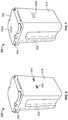
- FIGS. 1A and 1Bdepict perspective views of an insulating container 100 .
- the insulating container 100may comprise a base portion 102 and a lid 104 that, in some examples, may be non-destructively, removably coupled thereto.
- the base portion 102may be an insulated structure forming a void for containing a liquid, as will be discussed more fully herein.
- the base portion 102may be cuboidal or substantially cuboidal in shape.
- the base portion 102may be prismoidal or substantially prismoidal (e.g., a pentagonal prism, hexagonal prism, heptagonal prism, or the like) in shape.
- the base portion 102may be substantially cylindrical in shape or may have a substantially trapezoidal cross section. Various other shapes may be used without departing from the invention.
- the base portion 102may include a first end 106 , having a bottom surface 108 .
- the bottom surface 108may be configured to support the insulating container on a surface, such as a table, the ground, a vehicle bed, or the like.
- the bottom surfacemay have a shape that is configured to correspond to a mounting structure in order to facilitate mounting and/or securing the insulating container 100 to, for example, a bed of a truck.
- cut-outs 107 shown in FIGS. 1A and 1Bmay be configured to align with a mounting structure arranged in the vehicle bed and may aid in securing the insulating container 100 to the vehicle bed.
- the base portion 102further includes a second end 110 defining an opening 112 (shown in FIG. 2 ) that may be used for filling the insulating container.
- the opening 112may be covered by lid 104 , when the insulating container is in use (e.g., when the insulating container is in a closed configuration).
- the base portion 102may further include a plurality of side portions 114 connected to the bottom surface that define a void for receiving liquid in the insulating container 102 .
- the side portions 114may be arranged such that they extend generally perpendicularly from the bottom surface.
- one or more handles 190may be arranged in one or more side portions 114 (or other region of the base portion 102 ).
- the handlesmay be integrally molded with the base portion 102 and may generally be an undercut formed in the side portion 114 of the base 102 .
- the undercut forming the handlemay include a recess extending along substantially all or a majority of the side portion 114 . This may provide ease of manufacturing the base 102 with the integrally molded handles 190 .
- the handles 190may be flush with an exterior surface of the base 102 in order to reduce the risk of breakage.
- the insulating container 100may be configured to contain, store, carry, etc., a volume of liquid. In some examples, the insulating container 100 may be configured to store between five (5) and ten (10) gallons (between 18.93 and 37.85 L) of a liquid. In some examples, the insulating container may be configured to store approximately five (5) gallons (approximately 18.93 L) of a liquid.
- the insulating containermay be configured to store at least four (4) gallons (approximately 15.14 L) of liquid, at least approximately three (3) gallons (approximately 11.36 L) of liquid, at least approximately two (2) gallons (approximately 7.57 L) of liquid, or at least approximately one (1) gallon (approximately 3.79 L) of liquid, among others.
- the insulating container 100may be configured to store materials in a solid or a gaseous state, or combinations thereof, without departing from the scope of the disclosure described herein.
- the insulating container 100(and various other containers described herein) may be sized to accommodate the volumes of liquid described above.
- the insulating container 100may be between 10 and 24 inches tall, between 10 and 24 inches wide, and between 10 and 20 inches deep.
- the insulating container 100may include a lid 104 .
- the lid 104may connect to the base 102 in a closed configuration using a press fit. Additionally or alternatively, other securing systems or devices may be used to secure the lid 104 to the base, as will be discussed more fully herein.
- the lid 104may be hinged such that it is connected to (either removably or permanently) the base 102 at a hinge 116 and may be rotated about the hinge 116 .
- the hingemay be one of various types of hinges, including a continuous piano hinge, double hinge, ball joint hinge, living hinge, and the like. These and various other hinge arrangements may be discussed more fully herein.
- the hinge 116may permit the lid 104 to be opened and rotated away from the base portion 102 , to allow access to the void defined by the base portion 102 (e.g., via opening 112 ).
- the hingemay facilitate rotation of the lid 104 from a closed configuration of the insulating container (e.g., when the lid is in place covering the void formed by the base) to an open configuration (e.g., when the lid is not covering the void formed by the base), and vice versa.
- base 102 and lid 104may include an exterior surface or outer shell 117 surrounding and enclosing an insulating portion 118 , as shown in FIG. 2 .
- the shell 117is typically formed from various materials, such as one or more metals, alloys, polymers, ceramics, or fiber-reinforced materials.
- the shell 117may be formed of a plastic material, such as polyethylene, that is molded to form both the base 102 and lid 104 portions.
- the insulating portion 118is formed of an insulating material that exhibits low thermal conductivity.
- the insulating portion 118may be formed of (or filled with) a polymer foam, such as polyurethane foam.
- the base 102 and lid 104 portionsare formed using a roto-molded process as would be understood by one of ordinary skill in the art (not shown).
- various other types of molding or other manufacturing processese.g., stamping, casting, forging, and the like may be used to form the insulating container without departing from the invention.
- the lid 104may be configured to remain connected to the base portion 102 in both an open configuration and a closed configuration. For instance, the lid 104 may be secured or locked in a closed position using latching devices 120 .
- the latching devices 120may be various types of latches, including a t-latch having a latch portion and a keeper portion, as well as various other types of latches.
- latching device 120that may be used with the insulating container 100 is described with reference to FIGS. 3 and 4 .
- the latching device 120 shown and describedis merely one example latch that may be used and various other types of latches may be used without departing from the invention.
- FIG. 3is a plan view of an example latching device 120 including a cut-away of an engaging portion.
- the latching device 120includes a latch portion 122 and a keeper portion 140 .
- the keeper 140includes 2 portions that extend along either side of a stem 126 of the latch 122 .
- the latch 122is connected to lid 104
- the keeper 140is connected to the base 102 .
- the latch 122may be connected to the base 102 while the keeper 140 is connected to the lid 104 . Accordingly, the latch 122 and keeper 140 are interchangeably positionable on either portion of the insulating container 100 .
- the latch 122is configured to be releasably engageable with the latch keeper 140 such that when the latch 122 is in an engaged relationship with the keeper 140 , the opposing lid portion 104 and base portion 102 are maintained in the closed, secured, and/or sealed position.
- the latch 122includes a latch base 130 , a stem or body portion 126 extending from the latch base 130 , an engaging portion 128 extending from the body portion 126 and a grasping portion 124 extending from the engaging portion 128 .
- the latch base 130 of the latch 122is arranged on one end of the latch 122
- the grasping portion 124is arranged on the opposite distal end of the latch 122 .
- the engaging portion 128is configured for locking, mating relationship with a recessed pocket or notched area 142 of the latch keeper 140 as will be discussed in more detail below.
- the latching device 120further includes a latch slot 145 .
- the latch slot 145may be integrally formed into the surface of the lid 104 .
- the latch slot 145is configured for receiving the latch 122 . For instance, at least a portion of the latch base 130 of the latch 122 is received within the latch slot 145 when the latch 122 is engaged with the latch keeper 140 .
- the latch 122is made of a flexible, stretchable, resilient, one-piece molded material that is typically pivotally attached to the lid portion 104 of the container 100 and received within a recessed, elongated latch slot 145 which is typically integrally molded to the container 100 .
- the latch 122may be molded in a single-piece construction from rubbery materials as would be understood by those of ordinary skill in the art.
- the latch 122may be formed of a material that is formed or made from a plastics material or another suitable material which can be formed or molded into a shape and thus retain the shape to which it has been formed.
- the latch 122may be made of sufficient size, thickness and materials of construction to withstand repeated cycles of stress as the latch is engage/disengaged with the latch keeper 140 over time.
- the material of constructionis one that is stretchable and/or resilient (e.g. EPDM or Neoprene rubber) such that when the latch 122 is extended or otherwise stretched to an elongated position, either to engage or disengage the latch keeper 140 , it rebounds or otherwise returns to its originally un-stretched state or partially stretched state to maintain sufficient tension to maintain the closed position, with little or no deformation.
- the latch 120is able to recoil or spring back or otherwise return into its original or near-original shape after bending, stretching, or being compressed and when in an un-stretched position.
- the latch 122is configured such that the grasping portion 124 extends from the body portion 126 at an angle that departs from the plane of the latch 122 .
- the angle between the grasping portion 124 and the body portion 126may aid in or facilitate grasping the latch 122 by a user. At this angle, the user is easily able to slip his or her fingers between the grasping portion 124 and the side of the base portion 102 of the insulating container 100 for disengaging the latch 122 from the keeper 140 .
- the latch 122is made from a resilient material, even though the latch extends from the body of the container, it is not easily dislodged or broken.
- the grasping portion 124is typically formed into a shape that is easily grasped by a user, and as shown in the figures, the grasping portion 124 is formed into a t-shape to facilitate grasping by a user. Without intending to be limited thereby, other shapes contemplated for the grasping portion 124 include y-shaped and tab-shaped (not shown), or a small flap of material extending from the engaging portion and capable of being grasped for manipulation of the latch.
- the latch keeper 140is integrally molded within the base portion 102 .
- the latch keeper 140includes an elongated keeper slot 141 and a recessed pocket 142 formed in the keeper slot 141 .
- the recessed pocket 142is typically configured for receiving the engaging portion 128 of the latch 122
- the keeper slot 141is typically configured for receiving the body portion 126 of the latch 122 .
- the body portion 126 of the latch 122is formed into a cross-sectional inverted triangular shape 143 and the elongated keeper slot 141 of the latch keeper 140 is also formed/molded into a complimentary triangularly shape receiving portion to match the body portion 126 of the latch 122 .
- the latch 122when the latch 122 is seated/received within the elongated keeper slot 141 , the latch 122 forms a friction fit with the elongated keeper slot 141 .
- the body portion 126 and elongated keeper slot 141could be formed into complimentary three dimensional pyramidal, square or rectangular shapes (not shown).
- engaging portion 128 of the latch 122may be formed into a ball-shape and the recessed pocket 142 of the latch keeper 140 is configured as a complimentary shaped socket 142 to receive the ball-shaped engaging portion 128 .
- the engaging portionis capable of taking any shape that is easily received by a reciprocatingly shaped recessed pocket formed in the latch keeper.
- the engaging portioncould be formed into any geometric shape, such as a triangle, square, and the like.
- the recessed pocket of the latch keeper 140would have a corresponding configuration capable of receiving the shaped engaging portion.
- the engaging portion of the latch and the recessed pocket of the latch keeperare shaped so as to be matingly coupled together.
- the recessed pockethas a shape configured to receive the engaging portion while providing a surface-to-surface contact area sufficient to maintain the closure.
- the latchincludes is an integrated ball and socket latching system for an insulating container 100 .
- the latch keeper 140is designed to be part of the mold of the insulating container 100 and an exact fit for the ball-shaped engaging portion 128 is molded on a stretchable rubber latch 122 having a t-shaped end. This combination provides a strong and very secure lid latching system.
- FIG. 3illustrates the latching device 120 in a closed position
- FIG. 4illustrates the latching device 120 in an open position
- the latching device 120When in a closed position, the latching device 120 is positioned such that the lid 104 abuts the base 102 of the insulating container 100 , thus closing, securing, and/or sealing the container.
- the grasping portion 124is pulled/stretched generally downward, toward the base 102 of the container 100 .
- the body portion 126 of the latch 122stretches so that the engaging portion 128 disengages from the latch keeper 140 .
- the latch 122Once the engaging portion clears the latch keeper 140 , the latch 122 is swung upward, away from the container, and in an arc.
- the latch 122is moved in a downward arc, toward the container 100 .
- the latch 122is once again extended/stretched downward, toward the base 102 and the body portion 126 of the latch 122 is seated/positioned within the keeper slot 141 , preferably in a friction fit as described above.
- the body portion 126 of the latch 122may be mostly recessed within the latch slot 145 and the keeper slot 141 , and, in some examples, does not extend or protrude beyond the surface thereof.
- the latch 122When the stretching force is removed from the latch 122 , the latch is free to attempt to return to its former state, thus allowing the engaging portion 128 of the latch 122 to become seated and received within the recessed pocket 142 of the latch keeper 140 , thus closing the latching mechanism.
- the latch 122is made of materials and sized such that when in the closed/seated position, enough force remains to maintain the closed position of the container. In other words, in the closed position, a certain amount of tension is maintained on the latch 122 as it is not completely returned to its unstretched position/state. In the closed position, the engaging portion 128 of the latch 122 is received within the recessed pocket 142 of the keeper slot 140 .
- the engaging portion 128is sized and shaped so as to provide maximum contact with the recessed pocket 142 , thus ensuring an easily maintainable closure.
- the hinged lid 104may be rotated away from the base portion 102 and may rest along a rear side 114 of the base portion 102 (e.g., the lid may rotate 270° from a closed configuration (e.g., the position shown in FIGS. 1A and 1B ) to an open configuration).
- the fully open position or configurationmay include at least a portion of a top, exterior surface of the lid 104 being in contact with a rear (or other) side portion 114 of the base portion 102 of the insulating container 100 .
- FIGS. 5A-5Dillustrate one example rotation of the lid 104 with respect to the base portion 102 from a closed position or configuration ( FIG. 5A ) to a fully open position or configuration ( FIG. 5D ).
- the lid 104is in a substantially closed position. That is, the lid 104 is substantially perpendicular to the base 102 and is covering the opening (not shown in FIG. 5A ).
- the lid 104may be lifted upward, in the direction of the arrow shown in FIG. 5A .
- the lid 104may then rotate about hinge 116 , as shown in FIG. 5B . That is, the lid 104 is now shown at an angle relative to the former perpendicular position (shown in FIG. 5A ) which indicates that the lid 104 is being opened.
- the lid 104may continue to rotate about hinge 116 , as shown in FIGS. 5C and 5D , until the lid 104 is in the fully open position shown in FIG. 5D .
- the fully open position or configurationmay be 270° from the closed position.
- FIGS. 6 and 7illustrate some example latching systems that may be used to hold the lid 104 in the fully open position.
- the insulating containers 200 and 300shown in FIGS. 6 and 7 , respectively, may be substantially similar to insulating container 100 (or various other insulating container described herein) and may include some or all of the features described with respect to insulating container 100 , or any other insulating container described herein.
- FIG. 6illustrates one arrangement in which the insulating container 200 includes latching devices similar to those discussed with respect to FIGS. 3 and 4 . That is, the latching devices include keepers on the front of the container (e.g., similar to container 100 shown in FIG. 1A including latching devices to secure the lid 104 in the closed position).
- a second set of keepers 240may be arranged on a rear or back side 214 (e.g., the side receiving the lid 204 when open) of the base 202 , as shown in FIG. 6 . Accordingly, when the lid 204 is in the fully closed position, the engaging portion of a latch (not shown) will be received in and engaged with keepers formed on the front of the insulating container (as shown in FIGS.
- the engaging portion of the latchmay be received in the keepers 240 formed on the rear side 214 of the base 202 to maintain the position of the lid 204 (e.g., to secure the lid 204 to the rear side 214 of the base 202 ).
- the keepers 240may be molded into the base 202 .
- a similar process to that described abovemay be used to engage/disengage the latch with the keepers 240 (e.g., when engaged with the keepers, grasping portion is pulled downward and rotated up, away from container, when disengaged, grasping portion is rotated downward, toward container and is stretched downward to engage the keeper).
- FIG. 7illustrates another example arrangement in which an insulating container 300 having a lid 304 may be secured in both an open configuration and a closed configuration.
- the insulating container 300includes a lid 304 and a base 302 .
- the lid 304 and base 302may have one of various types of securing arrangements to secure the lid 304 to the base 302 when the lid 304 is in the closed configuration.
- the insulating container 300may include an open configuration latching system including a plurality of magnets 350 a , 350 b .
- a first magnet 350 amay be arranged on a top, exterior surface 303 of the lid 304 .
- a second magnet 350 bmay be arranged on a rear side 314 of the base 302 in a position corresponding to the position of the first magnet 350 a when the lid 304 is in a fully open position. Accordingly, when the lid 304 is in the fully open position (e.g., rotated approximately 270° from the closed position), the first magnet 350 a and second magnet 350 b may be in proximity to each other and may engage via a magnetic force (i.e., may be magnetically attracted to each other to secure the lid 304 in the open configuration). The magnetic force may be strong enough to secure the lid 304 in the fully open position relative to the base 302 .
- a force applied to the lid 304may be sufficient to overcome the magnetic force and the lid 304 may be rotated to the closed position, as desired.
- the arrangement of FIG. 7includes a first magnet 350 a arranged on the lid 304
- substantially all of the exterior surface 303 of the lid 304may be magnetic. Accordingly, in such arrangements, the placement or position of magnet 350 b may vary because a greater portion of the surface may be available to engage with magnet 350 b .
- magnets 350 a , 350 bmay also be used to display a logo or name of a company or manufacturer of the insulating container (e.g., a magnetic plate may be used that may display the logo or name).
- FIGS. 6 and 7are merely some example securing arrangements.
- a protrusione.g., male portion
- a corresponding recesse.g., female portion
- the protrusionmay be received in the recess and the lid may be secured via a snap fit.
- the lidmay be pulled away from the base to overcome the snap fit.
- the protrusionmay be formed on the base while the corresponding recess may be formed in the lid.
- a lid of the insulating containermay be secured in both an open configuration and a closed configuration may allow the insulating container to be used in a variety of manners without concern for the lid falling off, being lost, etc.
- the insulating containermay be secured in the bed of a vehicle, such as a pickup truck.
- the lidWhen driving, the lid may be secured in either the open configuration or the closed configuration to ensure that the lid is not lost due to wind, driving conditions, etc.
- FIG. 8illustrates another example arrangement of an insulating container 400 having a rotatable lid.
- the insulating container 400may include a double hinge arrangement. That is, each hinge 406 a , 406 b may have two pivot points to enable opening and closing of the lid 404 with respect to the base 402 .
- the lid 404may pivot with respect to point 408 (shown on hinge 406 b but also on hinge 406 a ), as well as point 410 (shown on hinge 406 b but also on hinge 406 a ).
- FIGS. 9A-9Cillustrate rotation of the lid 404 from the closed configuration to the open configuration.
- FIG. 9Ashows the lid 404 in a closed configuration with respect to the base 402 .
- FIG. 9Billustrates the lid 904 as partially open with respect to the base 402 .
- the lid 404is being rotated in direction of arrow 405 from the closed configuration to an open configuration.
- FIG. 9Cillustrates the lid 404 in a fully open position with respect to the base 402 .
- the lid 404has been further rotated in the direction of arrow 407 to open the lid 404 .
- the lid 404may rotate from a closed configuration (e.g., shown in FIG. 9A ) through an arc of between 90° and 270° to the open position.
- the hinge 406 a , 406 bmay be configured to aid in maintaining the lid 404 in the open position with respect to the base 402 .
- FIGS. 10A and 10Billustrate one example hinged lid arrangement in which the lid may be removably connected to the base of the insulating container.
- FIG. 10Aillustrates a portion of an insulating container 500 .
- the insulating container 500may be substantially similar to various other insulating containers (e.g., 100 , 200 , 300 , 400 , etc.) described herein and may include one or more features described with respect to one or more other insulating containers.
- the removable lid 504is shown substantially perpendicular to the base 502 in the closed configuration of FIG. 10A . Accordingly, to open the lid 504 (and subsequently remove it from the base 502 ), the lid 504 may be rotated in the direction of arrow 505 in FIG. 10B .
- the lid 504may be rotated around hinge 516 until first securing portion 570 (e.g., an end point of securing portion 570 ) is clear of second securing portion 572 (e.g., end point of second securing portion 572 ). At that point, the lid 504 may be lifted upward, in the direction of arrow 507 , to completely detach or remove the lid 504 from the base 502 . To replace the lid 504 , the lid 504 may be lowered toward base 502 until first securing portion 570 is aligned with and/or in contact with second securing portion 572 . Once the first and second securing portions are aligned and/or in contact, the lid 504 may be rotated downward, as indicated by arrow 505 , toward the base 502 .
- first securing portion 570e.g., an end point of securing portion 570
- second securing portion 572e.g., end point of second securing portion 572
- lid 504 that is non-destructively removable from the base 502 of the insulating containermay include one or more latching or securing arrangements, as discussed above.
- lid 504may be removable from the base 502 , a user may desire to secure the lid 504 to the base 502 in an open configuration.
- lid 504may include latches or a magnet (as discussed above with respect to lids 504 , 504 in FIGS. 6, 7 , respectively) to secure the lid 504 to a panel of the base 502 (similar to the arrangements discussed above with respect to FIGS. 6 and 7 ).
- first securing portion 570 and second securing portion 572may include a protrusion or stop 575 .
- the protrusionmay be configured to prevent the lid 504 from rotating beyond the stopping point and inadvertently become detached from the base 502 . Accordingly, in arrangements having a stop, the lid 504 may be rotated to a point at which the stop 575 is engaged and, if a user desires to remove the lid 504 , the user may apply an additional force to overcome the stop and subsequently remove the lid 504 from the base 502 .
- the insulating containermay include a gasket or other sealing device.
- the gasketmay be arranged in either the lid or the base and may aid in sealing the lid and base when the lid is in a closed configuration.
- the gasketmay be seated in a recess formed in at least one of the base and the lid and extending around a perimeter of the at least one of the base or the lid. The gasket may aid in maintaining the temperature of the liquid contained within the insulating container.
- One example gasket arrangementis shown in FIGS. 10A and 10B , although this and various other gasket arrangements may be used with any of the insulating containers described herein.
- the gasket 560is arranged in a recess or channel 564 in the base 502 .
- the gasket 560may be arranged in a recess or channel formed in the lid 504 .
- a protrusion 562 having a shape corresponding to recess 564may contact the gasket 560 and compress the gasket 560 and aid in sealing the lid and base in the closed configuration.
- the gasketmay include strategically placed cut-outs that may reduce or eliminate a need for a vent (e.g., a vent to prevent lid lock), as will be discussed more fully below.
- the gasketmay be a traditional gasket having a substantially circular cross section. In other examples, the gasket may have a particular cross section configured to aid in venting the insulating container.
- FIGS. 11A and 11BOne example arrangement is shown in FIGS. 11A and 11B .
- the gasket 600 a , 600 b shownincludes a base region 602 that may be received in a recess 604 in either a lid 606 or base 608 of an insulating container.
- the gasket 600may include a V-shaped or substantially V-shaped portion or extension 610 connected to the base or stem region 602 and extending outward from the recess 604 and into a space in which the lid 606 and base 608 meet with the insulating container is in a closed configuration.
- the V-shaped portion 610may extend generally horizontally from the base region 602 . That is, the V-shaped portion 610 may include a first side of the “V” 612 , that may be in contact with the base or stem region 602 in a substantially horizontal configuration. A second side of the “V” 614 may extend from one end of the first side 612 at an angle to side 612 , thereby forming a V-shaped arrangement from the two sides 612 , 614 .
- This V-shaped arrangementmay aid in permitting venting of the interior of the insulating container with the insulating container is in a closed configuration.
- the V-shaped arrangementmay aid in preventing leakage from the insulating container (e.g., of water or other fluids) while permitting at least some air to escape from the interior of the insulating container.
- the gasket 600may include at least one venting hole or a plurality of venting holes.
- the V-shaped portion 610 amay be arranged with the open area of the “V” (e.g., an end of side 612 not connected to side 614 ) facing away from an interior 616 of the insulating container.
- the open area of the “V” 610 bmay face toward the interior 616 of the insulating container.
- a gasketmay be formed in two or more sections. The two or more sections may include portions having the “V” facing in different directions.
- FIG. 12illustrates one example gasket arrangement in which different sections of gasket having a “V” facing in different directions may be used.
- FIG. 12illustrates three gasket sections, 700 a , 700 b , 700 c .
- sections 700 a and 700 cmay instead be a single gasket piece with section 700 a representing one end of the gasket and 700 c representing another end of the gasket.
- sections 700 a and 700 cmay include a gasket arrangement in which the “V” portion faces the interior of the insulating container (as shown in FIG. 11B ), while section 700 b may include a gasket arrangement in which the “V” portion faces away from an interior of the insulating container (as shown in FIG. 11A ).
- sections 700 a and 700 cmay include a V portion facing away from the interior, while section 700 b includes a V portion extending toward the interior.
- FIG. 12Although three sections are shown in FIG. 12 , more sections may also be used in such an arrangement.
- the additional sectionsmay be arranged in various patterns of gasket arrangements to enhance venting of the interior of the insulating container without departing from the invention.
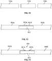
- FIG. 13illustrates another gasket arrangement which may be used in one or more insulating container configurations.
- the gasket shownincludes a first section 800 a and a second section 800 b .
- sections 800 a and 800 bmay be separate and distinct sections of gasket material or may be two ends of a single piece of gasket material.
- ends 801 a , 801 b of each section 800 a , 800 bmay abut each other (e.g., when the gasket is installed in either a lid or base of an insulating container).
- tape or other adhesive material 802may be applied to the gasket.
- the adhesive 802may extend from section 800 a to section 800 b and may span abutting ends 801 a , 801 b.
- FIG. 14illustrates another example gasket arrangement. Similar to the arrangement of FIG. 13 , the gasket may include a first section 900 a and a second section 900 b which may be two distinct sections or may be opposite ends of a single section of gasket material. Unlike the arrangement of FIG. 13 in which the ends of each section are abutting, end 901 a of section 900 a and end 901 b of section 900 b are not abutting. Instead, the ends 901 a , 901 b , are separate from each other to define a gap 904 between each end 901 a , 901 b , of each section 900 a , 900 b . Similar to FIG.
- an adhesive portion 902may be used to aid in maintaining a position and/or arrangement of the gasket.
- the adhesive portion 902may extend from section 900 a to section 900 b and may span end 901 a , 901 b , as well as gap 904 . This arrangement may aid in providing venting means for the interior of the insulating container.
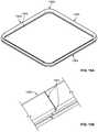
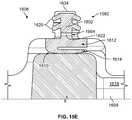
- FIGS. 15A-15Eillustrate another exemplary gasket arrangement configured to seal the lid 1606 to prevent the spillage of liquids, and wherein the insulating container is also configured to be paired with and mounted to an insulating container mount 1810 .
- the insulating container 1800may comprise a spigot 1880 , a gasket 1560 , and a lid 1606 that may be, non-destructively, removably coupled thereto in accordance with the disclosure herein.
- FIG. 15Aillustrates another example gasket.
- Gasket 1560includes bonded ends 1902 and at least one venting hole 1904 .
- the venting holes 1904reduce or eliminate the need for a vent to prevent lid lock from changes in pressure inside and outside the insulating container.
- the venting holes 1904are configured to allow air or fluid to exit or enter an interior void of the insulating container 1800 to equalize the internal pressure of the insulating container with the atmosphere or external pressure.
- the gasket 1560may include a plurality of venting holes 1904 .
- the gasket 1560may include three venting holes.
- the gasket 1560may include a front venting hole 1906 .
- the front venting hole 1906may be arranged on the side of the insulating container from which the lid 1804 is opened. In other configurations, the front venting hole 1906 may actually be configured on the back side of the insulating container 1800 where the lid 1804 is coupled to the insulating container 1800 .
- the venting holes 1902may be configured on the sides of the insulating container 1800 when the gasket 1560 is mounted to the insulating container.
- Gasket 1560may have a substantially square shape or a substantially rectangular shape. Gasket 1560 may have a corresponding shape that conforms to the opening of the insulating container, for example opening 112 .
- the gasket 1560has a unique profile or cross section configured to aid in venting the insulating container.
- Gasket 1560may include a base or stem region 1602 that may be received or anchored in recess 1604 in either a lid 1606 or base 1608 of an insulating container.
- the recess 1604runs along the entire perimeter of the underside of the lid 1606 or the perimeter of the top of the base 1608 .
- the gasket 1560may include a V-shaped or substantially V-shaped portion or extension 1610 connected to the base or stem 1602 and extending outward from the recess 1604 and into a space in which the lid 1606 and base 1608 meet with the insulating container in a closed configuration.
- venting hole 1904may aid in permitting venting of the interior of the insulating container with the insulating container is in a closed configuration.
- the V-shaped arrangementmay aid in preventing leakage from the insulating container (e.g., of water or other fluids) while permitting at least some air to escape from the interior 1616 of the insulating container.
- venting hole 1904provides a channel 1622 through the base or stem region 1602 to allow air to escape from the interior 1616 or allow air to enter the interior 1616 of the insulating container to equalize the pressure preventing lid lock.
- venting holes 1904extend from an outside edge of the gasket wall to an interior gasket wall forming the channel 1622 .
- the venting hole 1904 and the channel 1622are configured to vent fluid (e.g., air, water, or other fluids) from or to the interior 1616 or an interior void of the insulating container that is formed by the sidewall structure and a bottom portion of the insulating container when the lid is in a closed position.
- the venting hole 1904 and the channel 1622are configured to provide a conduit to the interior 1616 of the insulating container.
- the V-shaped portion or extension 1610may include a first side of the “V” 1612 , that may be in contact with the base or stem region 1602 in a substantially horizontal configuration.
- the base or stem region 1602is substantially perpendicular to the first side 1612 .
- a second side of the “V” 1614may extend distally or away from one end of the first side 1612 at an angle 1618 , thereby forming a V-shaped arrangement from the two sides 1612 and 1614 .
- the V-shaped portion or extension 1610may extend generally away or opposite (i.e., distally) from the base or stem portion 1602 .
- the angle 1618may be from about 30-60 degrees when the container is in an open configuration.
- the angle 1618may be about 45 degrees when the container is in an open configuration.
- base or stem region 1602may include a plurality of prongs 1620 .
- prongs 1620are configured to be inserted into the groove or recess 1604 runs along the entire perimeter of the underside of the lid 1606 or the perimeter of the top of the base 1608 to assist with the anchoring of the gasket 1560 in the insulating container.
- gasket 1560may include at least one bonded end 1902 or a plurality of bonded ends 1902 .
- the gasket 1560is arranged in a recess or channel 564 in the base 502 .
- the gasket 560may be arranged in a recess or channel formed in the lid 504 .
- a protrusion 562 having a shape corresponding to recess 564may contact the gasket 560 and compress the gasket 560 and aid in sealing the lid and base in the closed configuration.
- the gasketmay include strategically placed cut-outs that may reduce or eliminate a need for a vent (e.g., a vent to prevent lid lock), as will be discussed more fully below.
- This alternative V-shaped arrangement that incorporates at least one venting holemay aid in permitting venting of the interior of the insulating container with the insulating container is in a closed configuration.
- the V-shaped arrangementmay aid in preventing leakage from the insulating container (e.g., of water or other fluids) while permitting at least some air to escape from the interior of the insulating container via at least one vent hole or a plurality of vent holes.
- the gasketis formed from a plastic, a rubber, a silicone, a flexible PVC, or other similar material.
- the V-shaped portion or extension 1610may be arranged with the open area of the “V” facing away from an interior 1616 of the insulating container.
- the open area of the “V”may face toward the interior 1616 of the insulating container.
- a gasketmay be formed in two or more sections. The two or more sections may include portions having the “V” facing in different directions.
- FIGS. 11-15may be used as shown in each figure or may be used in combination with each other without departing from the invention.
- a portion of the basemay include a material that is breathable for air but does not permit water or other liquids to penetrate. This mesh material may allow venting without permitting spillage of the liquid contained within the insulating container.
- FIG. 16illustrates another example insulating container 1000 having a hinge arrangement that permits the lid 1004 to be removed from the base 1002 .
- the arrangement shown in FIG. 16is merely one example of a quick release arrangement that may be used with one or more aspects of the insulating containers described herein.
- the insulating container 1000includes two hinged portions 1006 .
- the hinged portions 1006are more clearly shown in FIGS. 16A-16C .
- the hinged portionsmay include an attaching member 1008 that connects to a rod or axel 1010 .
- the rod or axelmay extend across at least a portion of a top, rear of the insulating container 1000 .
- the rod or axel 1010may extend across the entire span of the top, rear portion of the insulating container.
- FIGS. 16A-16Cillustrate one example method of removing the lid 1004 from the base 1002 of the insulating container 1000 .
- FIG. 16Aillustrates the lid 1004 in a generally closed configuration with respect to the base 1002 .
- the attaching member 1008may rotate around rod or axel 1010 .
- the lid 1004may continue to be rotated until it is pulled toward a rear of the insulating container and removed from the base, as shown in FIG. 16C .
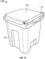
- FIG. 17illustrates yet another example of an insulating container 1100 having a removable lid.
- the insulating containerincludes a lid 1104 configured to rotate about a rod or axel 1110 . Upon reaching a certain point in the rotation, the lid 1104 may be removed from the base 1102 , as shown in FIGS. 18A-18C .
- FIG. 18Aillustrates the lid 1104 in a closed configuration relative to the base 1102 .
- the lid 1104has been moved upward, in the direction of arrow 1105 , and thereby rotates about axel 1110 .
- the lid 1104may be pulled toward a front of the insulating container 1100 (in the direction of arrow 1107 ) and thereby removed from the base 1102 , as shown in FIG. 18C .
- FIGS. 19-21illustrate one example hinge insert 1250 that may be used in conjunction with one or more hinge arrangement discussed herein.
- FIG. 22illustrates another insulating container 1300 having various advantageous features.
- the insulating container 1300may be similar to other insulating containers described herein (e.g., 100 , 200 , 300 , 400 , etc.) and may include one or more of the other features described with respect to the insulating containers described herein.
- the insulating container 1300includes a lid 1304 and a base 1302 .
- the lid 1304may be secured to the base 1302 using latching arrangements 1320 , similar to the arrangements discussed above. Further, the lid 1304 may be rotatable and/or removable relative to the base, as discussed herein.
- the insulating container 1300may include a spigot 1380 .
- the spigot 1380may protrude from the base 1302 and may be configured to dispense liquid stored in the insulating container.
- the spigot 1380may include a valve such that, the liquid may be contained within the insulating container 1300 until a user desires to dispense a portion of the liquid (e.g., the valve defaults to an off position). The valve may then be opened to permit liquid to flow through the spigot 1380 . When the desired amount of liquid is dispensed, the valve may be closed to prevent further liquid from dispensing.
- the spigot 1380may include an indicator, such as a color indicator, audible indicator, etc. to indicate when the spigot is on.
- Various types of spigot arrangementsmay be used with the insulating container without departing from the invention.
- the spigot 1380may be contained within a recess 1382 formed in the base 1302 .
- the spigot 1380may be mostly contained within the recess 1382 in order to protect the spigot 1380 from damage. For instance, sufficient impact with the spigot 1380 may cause it to crack or be sheared off. Accordingly, by positioning the spigot 1380 within the recess 1382 , much of the spigot 1380 may be protected by the portion of the base 1302 surrounding it. In some examples, 100% of the spigot 1380 (the entire spigot) may be contained within the recess 1382 such that no portion of the spigot 1380 extends beyond an exterior surface of the base 1302 .
- At least 90% of the spigot 1380may be contained within the recess (at most 10% of the spigot 580 may protrude beyond exterior wall 1314 of the base 1302 ), at least 75% of the spigot 1380 may be contained within the recess (with 25% protruding outward from exterior wall 1314 ), at least 50% may be contained within the recess (with 50% protruding outward from exterior wall 1314 ), at least 30% may be contained within the recess (with 70% protruding outward from exterior wall 1314 ), and the like.
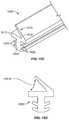
- the insulating container 500may include one or more guards 1384 that may be used to protect spigot 1380 .
- the guard 1384may extend outward from an edge of the recess 1382 , over the spigot, to an opposite edge of the recess 1382 . Accordingly, any object or force directed at the spigot 1380 would be intercepted by the guard 1382 .
- the guard 1384may be molded into the base 1302 or may be formed separately from the base 1302 and connected to the base 1302 .
- the guard 1384may be connected to the base 1302 using fasteners, a snap fit, adhesives, or the like.
- the guard 1384may be formed of various plastics, metals such as aluminum, steel, etc., composites, and the like.
- the guardsmay be arranged such that portions of each guard extend parallel or substantially parallel to other guards 1384 .
- the guardmay include one or more portions 1385 extending perpendicularly between parallel guards 1384 . This may provide additional protection of the spigot 1380 from small objects such as rocks, stones, or the like.
- the guard 1384may be arranged around the spigot 1380 such that it does not interfere with operation of the spigot 1380 . For instance, a user may be able to easily access the valve portion of the spigot 1380 to dispense liquid or cease dispensing liquid. Further, in arrangements in which the user may be filling a container such as a cup, water bottle, or the like, from the spigot 1380 , the guard 1384 may be arranged above the spout portion of the spigot 1380 so as not to interfere with placement of the container.
- FIGS. 23 and 24illustrate another spigot guard arrangement 1394 .
- the spigot 1380 shownmay be any suitable type of spigot 580 and, as shown in FIG. 24 , may protrude through a sidewall 1330 of the insulating container.
- one or more portions of the spigot 1380may be formed of stainless steel, aluminum, composite, synthetic materials such as NYLON, and the like.
- FIGS. 23 and 24are shown in isolation. However, the spigot shown 1380 may be used in various types of insulating containers, including those described herein.
- the spigot guard 1394protrudes outward from the sidewall 1330 of the insulating container.
- the spigot guard 1394includes two side portions 1396 that extend from the sidewall 1330 and a center portion 1398 joining one end of each of the two side portions 1396 .
- the spigot guard 1394may have curved portions where the side portion 1396 meets an end of the center portion 1398 .
- the connectionmay be made at an angle, such as a right angle.
- the center portion 1398extends over a top of the spigot 1380 in order to protect the spigot 1380 from damage. For instance, an article falling near the insulating container or thrown at the insulating container may break a spigot in a conventional arrangement. However, the spigot guard 1394 may protect the spigot from object that may cause damage to the spigot.
- the spigot guard 1394may be integrally molded in a sidewall 1330 of the insulating container (e.g., one piece with the sidewall or base). In another example, the spigot guard 1394 may be formed as a separate piece and joined to the sidewall 1330 via fasteners, adhesives, and the like.
- an insulating containermay have one or more handles formed in the base portion.
- FIGS. 25-27illustrate various additional handle arrangements that may be used with one or more of the insulating containers described herein.
- FIG. 25illustrates an insulating container 1400 having a handle arrangement 1492 formed in base 1402 .
- the handle arrangementincludes an undercut 1492 molded into the base portion 1402 . Because the undercut handle 1492 is integrally molded with the base 1402 , the handle is not likely (or less likely) to be broken (e.g., if the insulating container is dropped, struck, or the like). For instance, the undercut handle 1492 is formed flush with an exterior surface of the base 1402 .
- handle 1492protrudes outward from the base 1402 . Handles that protrude outward from the base may be more likely to be broken, etc.
- undercut handle 1492is shown on one side of base 1402 , a second undercut handle may be formed on an opposite side of the base 1402 to permit even carrying of the insulating container.
- the insulating container 1400may include a second handle arrangement 1495 in addition to the undercut handle 1492 .
- the insulating containermay include secondary handle 1495 that may be a piece formed separately from the base 1402 and connected thereto.
- the handle 1495may be connected to the base 1402 at each of two stem portions 1496 (only one stem portion is visible in FIG. 25 , however a second stem portion may extend from opposite end of cross bar 1497 ).
- the two stem portionsmay be connected by a cross bar 1497 which may form the hand engaging portion.
- the handle 1495may pivot with respect to the base 1402 such that, when not in use, the handle may be received in recess 1498 formed in side wall of base 1402 . When in use, the handle 1495 may be rotated outward from the recess 1498 such that a user may grip the cross bar 1497 to carry the insulating container.
- handle 1495may be formed of various suitable materials, such as one or more plastics.
- the handle 1495may have a core formed of polyvinyl chloride and an outer portion formed of ethylene vinyl acetate.
- the handle 1495is shown in FIG. 25 as having a solid structure, in some arrangements, the handle 1495 may have less structure and, instead may be formed of rope (such as polyester rope) that may be durable.
- the insulating container 1400may include only handle 1492 or only handle 1495 .
- FIG. 26illustrates another handle arrangement according to one or more aspects described herein.
- the insulating container 1500may be substantially similar to the various other insulating containers described herein and may include one or more features discussed with respect to other insulating containers described herein.
- Insulating container 1500may include an undercut handle 1590 formed in the base 1502 . Similar to handle 1492 , handle 1590 may be flush with the exterior surface of the base 1502 to avoid breakage of the handle. In some arrangements, insulating container 1500 may include a secondary handle arrangement 1595 . Secondary handle 1595 may be similar to handle 1495 discussed with respect to FIG. 25 .
- FIG. 27illustrates yet another insulating container 1600 arrangement.
- the insulating container 1600may be similar to various other insulating containers described herein and may include one or more features described with respect to those insulating containers.
- insulating container 1600includes an undercut handle 1690 , as well as a secondary handle arrangement 1695 .
- the insulating container 1600may include only the undercut handle 1690 .
- FIG. 28illustrates one example insulating container 1700 having one example spigot 1780 and spigot guard 1784 arrangement according to one or more aspects described herein.
- the example spigot 1780 and/or spigot guard 1784 arrangements described hereinmay be used alone or in combination with various different insulating containers and are not limited to use only with the insulating container shown in the figures or described herein.
- the insulating container 1700may include a base portion 1702 having a plurality of sides 1714 forming a sidewall structure and a bottom portion (not shown in FIG. 28 ).
- the sidewall structure and bottom portion forming the base 1702may define an interior void of the insulating container (similar to various other interior void arrangements discussed herein).
- the insulating container 1700may, in at least some examples include a lid 1704 .
- the insulating container 1700may include a spigot 1780 extending through a side 1714 of the base portion 1702 and between an interior void of the insulating container 1700 and an exterior of the insulating container 1700 .
- the spigot 1780may be configured to permit and/or control a flow of fluid stored in the interior void in the insulating container from the interior void to an exterior of the insulating container 1700 (e.g., to dispense fluid).
- the spigot 1780will be discussed more fully with respect to FIGS. 29-32 .
- the spigot 1780may generally include three regions.
- a first region 1780 amay extend outward from an exterior of a side 1714 of the insulating container 1700 .
- a second region 1780 bmay extend through a side 1714 of the insulating container 1700 (e.g., may be within the sidewall of the insulating container and, thus, not generally visible when the spigot 1780 is installed).
- a third region 1780 cmay extend from an interior of a side 1714 of the insulating container inward, toward the interior void of the insulating container.
- the spigot 1780may be configured to be disassembled and removed from the insulating container (e.g., for cleaning, etc.) and reassembled within the insulating container 1700 .
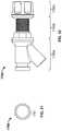
- the spigot 1780may include a spigot body 1785 having a spout 1782 extending therefrom (e.g., downward, at an angle) for dispensing fluid.
- the spigot body 1785may be configured to house portions of the spigot assembly, such as a spring 1786 , portions of a spigot valve rod 1787 , and the like, when the spigot 1780 is assembled in the insulating container 1700 .
- the spigot valve rod 1787(when assembled) may extend through the spigot body 1785 when assembled, through the spring 1786 , and may thread (e.g., via end threaded region 1788 shown in FIG. 30 ) into a dispensing button 1781 .
- the button 1781may include a finger engaging portion 1781 a which a user may depress in order to dispense fluid.
- the button 1781may further include an interior portion 1781 b which may be configured to be received in an aperture 1790 formed in an end of the spigot body 1785 .
- the aperture 1790may include one or more flat portions (e.g., flat portion 1791 shown in FIG. 31 ) which may prevent the button 1781 from rotating during use.
- flat portion 1791shown in FIG. 31
- any attempted rotation of the button, either during use or assembly,may be reduced or prevented by the flat portion 1791 contacting the interior portion 1781 b of the button 1781 .
- additional flat portionsmay be used or other shapes which may prevent turning of the button 1781 may be used without departing from the invention.
- the spigot assembly 1780may be configured to be disassembled and reassembled to permit cleaning of one or more parts of the spigot assembly 1780 .
- Assembly of the spigot 1780may involve extending the spigot valve rod 1787 through a wall 1714 of the insulating container 1700 and through the spigot body 1785 and spring 1786 and into the button 1781 .
- the threaded end 1788 of the threaded valve rodmay screw into or otherwise connect to the button 1781 when assembled.
- threaded portion 1788 of spigot valve rod 1787may be received by a mating threaded portion on an interior of the button 1781 .
- the spigot nut 1784may be connected to the spigot assembly 1780 from an interior of the insulating container 1700 to connect the spigot 1780 .
- the spigot nut 1784may be threaded onto threaded portion 1783 of the spigot body 1785 to fix the spigot assembly 1780 in place within the insulating container 1700 .
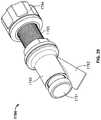
- An assembled spigot assembly(shown in isolation without the insulating container) is shown in FIGS. 29 and 32 .
- the spigot assembly 1780 and portions thereofmay be formed of various suitable materials.
- one or more components of the spigot assemblymay be formed of stainless steel, plastic, composite, or other suitable materials.
- the insulating container 1700may include a spigot guard 1794 .
- the spigot guard 1794 shownmay be used in combination with the spigot assembly 1780 shown, with another spigot assembly, or the like.
- the spigot guard 1791may be arranged on a same side 1714 of the insulating container as the spigot 1780 and may be configured to protect the spigot 1780 in case the insulating container 1700 is receives an impact force (e.g., is dropped, is struck, or the like).
- the spigot guard 1794will be discussed more fully herein with respect to FIGS. 33-36 .
- the spigot guard 1794may be arranged on a side 1714 of the insulating container 1700 in a location proximate the spigot 1780 .
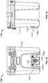
- the spigot guard 1794may include spigot side guards 1795 a , 1795 b and a spigot cross guard 1796 .
- spigot guard 1794may include two spigot side guards 1795 a , 1795 b arranged on either side of a spigot region (e.g., a region from which the spigot 1780 protrudes from the insulating container 1700 ).
- the spigot side guards 1795 a , 1795 bmay be integrally formed the base portion (e.g., sidewall structure, wall, etc.) of the insulating container 1700 .
- the spigot side guards 1795 a , 1795 bmay be molded into the side 1714 of the insulating container 1700 when the insulating container is formed.
- the spigot side guards 1795 a , 1795 bmay be formed as a single piece with the base of the insulating container 1700 . This may aid in efficiently manufacturing the insulating container.
- the spigot side guards 1795 a , 1795may be formed as solid portions of material or may be formed as hollow guards to permit additional insulating to be provided in a void created by the hollow side guards 1795 a , 1795 b .
- the spigot side guards 1795 a , 1795 bmay be double-walled, similar to the double-walled arrangements used in the base 1702 and/or lid 1704 .
- the spigot side guards 1795 a , 1795 bmay protrude outward from the side 1714 of the insulating container 1700 .
- at least a portion of the spigot side guards 1795 a , 1795 bmay protrude outward, from an exterior surface of the side 1714 of the insulating container 1700 in order to protect the spigot 1780 from, for example, a shear force.
- the spigot side guards 1795 a , 1795 bmay protrude outward between 50 and 60 millimeters from the exterior surface of the side 1714 .
- the spigot side guards 1795 a , 1795 bmay taper from one end of the side spigot guard 1795 a , 1795 b to an opposite end of the side spigot guard 1795 a , 1795 b .
- the spigot side guard 1795 bmay extend a greater distance outward from the side 1714 of the insulating container 1700 at an end proximate a bottom of the insulating container 1700 than at an end distal the bottom of the insulating container 1700 . This streamlined arrangement may accommodate the spigot cross guard 1796 .
- the spigot guard 1794may include a spigot cross guard 1796 .
- the spigot cross guard 1796may extend horizontally across a spigot region and between the first spigot side guard 1795 a and the second spigot side guard 1795 b .
- the spigot cross guard 1796may protect the spigot from, for example, objects falling downward onto the spigot 1780 .
- the spigot cross guard 1796may be formed as a component separate from the remainder of the insulating container 1700 or base 1702 of the insulating container 1700 .
- the spigot cross guard 1796may then be connected to the base 1702 via one or more fasteners, such as screws, adhesives, or the like.
- screws or other fastenersmay extend through apertures 1797 in the spigot cross guard 1796 to connect the spigot cross guard 1796 to the base 1702 of the insulating container 1700 .
- the spigot cross guard 1796may be formed of one or more suitable materials, such as various metals, including aluminum, stainless steel, and the like. In some examples, the spigot cross guard 1796 may be formed of one or more plastics or composite materials.
- portions of the spigot cross guard 1796may extend outward from the exterior surface of the side 1714 of the insulating container 1700 .
- the spigot cross guard 1796may have a tapered arrangement such that a first end and a second end are substantially flush with and/or in contact with the exterior surface of the side 1714 , while a central portion extending between the first end and the second end may protrude outward, away from the exterior surface of the side 1714 , thereby forming a gap between the spigot cross guard 1796 and the exterior surface of the side 1714 of the insulating container.
- the exterior surface of the side 1714may correspond to a recessed area in which the spigot 1780 is arranged. Accordingly, in these example arrangements, the gap may be formed between the spigot cross guard 1796 and the recessed exterior surface of the side 1714 of the insulating container.
- this gapmay be sufficiently sized to be used as a handle for lifting the insulating container 1700 .
- the distance A between an exterior surface of the central region of the spigot cross guard 1796 and an interior facing surface of the first end and the second end of the spigot cross guard 1796may be between 0.75 and 2.0 inches.
- a length B of the central portion of the spigot cross guard 1796may be between 2 inches and 6 inches, in some example arrangements.
- the spigot and spigot guard arrangementsmay be used in combination with one or more other aspects of various insulating containers including, for example, the insulating containers described herein.
- the spigot arrangementallows for ease of assembly/disassembly in order to facilitate cleaning of the spigot.
- the spigot guard arrangementsmay aid in preventing or reducing damage to the spigot in the event the insulating container is struck, dropped, falls, etc.
- the shape and position of the spigot side guardsmay aid in reducing or preventing damage to the spigot in the event the insulating container is subjected to, for example, a side force or front face force.
- the spigot cross guardmay aid in preventing or reducing damage to the spigot in the event the insulating container is subjected to, for example, a downward force along a front face or a front face force.
- the spigot guard arrangements described hereinmay aid in preventing or reducing damage to the spigot from additional forces or force directions.
- the insulating container 1800may comprise a spigot 1880 and a lid 1804 that, may be non-destructively, removably coupled thereto in accordance with the disclosure herein.
- the base portion 1814may be an insulated structure forming a void for containing a liquid or other contents that are desired to be hot or cold.
- the insulating containeris configured to include a spigot guard 1881 and a notch 1811 in the front of the mount 1810 to accommodate the spigot 1880 .
- the insulating containermay be configured to dispense fluid while secured to the insulating container mount 1810 .
- the insulating container 1800is mounted to the insulating container mount 1810 and secured in place by one or more hook points or flat hooks 1840 .
- the container mount 1810provides a flat surface that may be placed on the ground or mounted to, for example, a vehicle or boat.
- the insulating container 1800is can be placed into or “mated” to the container mount 1810 .
- the container mount 1810is configured in such a manner that the bottom surface 108 of the insulating container 1800 fits into the mount 1810 that is specifically formed in a shape that matches the profile of the bottom surface 108 of the insulating container 1800 .
- the arrangementallows the container 1800 and the mount 1810 to mate together in a secure fashion to stabilize and secure the insulating container 1800 .
- the mount 1810provides a stable platform and the insulating container 1800 may be further secured to the mount by straps 1850 that prevent movement of the insulating container 1800 .
- the insulating container mount 1810itself may be secured to a base or surface such as the deck of a boat or the floor of a vehicle without the insulating container 1800 .
- Such a configurationpermits an individual to easily remove the insulating container 1800 from, for example, a vehicle after transport or refilling. The configuration then permits an individual to quickly place the insulating container 1800 back into the mount 1810 , where it can again be secured for transport.
- the straps 1850may secure the insulating container 1800 to the mount 1810 in such a manner as to allow the hinged locking lid 1804 to rotate from a closed position to an open position that is approximately 270° from the closed position to allow for refilling or for access to the contents stored therein while mounted, and/or be non-destructively removable (e.g., able to be removed and replaced) from a base portion 1814 of the insulating container 1800 .
- the mount 1810is configured in such a manner that when the insulating container 1800 is mated and secured to the mount 1810 , an individual may use the spigot or spout 1880 arranged on the insulating container 1800 to dispense liquids or other fluids.
- FIG. 40Adepicts the top side of the anchor points 1890 , ratchet buckle 1830 , and hook point or flat hook 1840 .
- the mountincludes a plurality of anchor points 1890 that are configured to receive the insulating container. In this case four anchor points 1890 are provided; however, it is contemplated that more or less may be included.
- the anchor pointsare configured to include an anchor point receptacle 1891 . In other configurations, the anchor point and/or the anchor point receptacle may be configured to secure the mount to a platform via a bolt, screw, pin, weld, or other fastening means.
- the bottom side of the anchor pointmay include a nonskid type of material to prevent the mount from sliding or moving across a platform or the ground.
- the nonskid materialmay include nonskid paint, tape, or pads, non-slip tape or pads, rubber (e.g. EPDM or Neoprene rubber), or other composite or synthetic material.
- the anchor pointmay include a material that decreases the friction of a platform or the ground and provides for the easy movement of the mount. In such a configuration, the mount may be engaged with the insulating container or without the insulating container.
- FIG. 37is a front view and FIG. 39 shows right and left side views of the insulating container 1800 mounted in the insulating container mount 1810 .
- FIG. 40Adepicts a top view of the mount 1810
- FIG. 40Bdepicts a front view of the mount with the hook points or flat hooks 1840 stowed in the slot or loop point 1861 when the insulating container is not tensioned to the mount.
- FIG. 40Cis a side view of the stowed tie down strap 1850 .
- FIG. 41depicts a front view
- FIG. 42depicts a top right perspective view
- FIG. 43depicts a right view of the insulating container mount 1810 without the insulating container 1800 .
- the insulating container mount 1810accommodates the base portion 1814 , and the mount 1810 may be cuboidal or substantially cuboidal in shape.
- the mount 1810may be prismoidal or substantially prismoidal (e.g., a pentagonal prism, hexagonal prism, heptagonal prism, or the like) in shape.
- the mount 1810may be substantially cylindrical in shape or may have a substantially trapezoidal cross section. Various other shapes may be used without departing from the invention.
- the mountis in the required shape configured to accept the insulating container.
- the mount 1810may include a notch 1811 in the front of the mount 1810 to accommodate the spigot 1880 .
- the side portions of the insulating containermay include one or more hook point fastener receivers in the form of slots 1820 .
- the hook point or flat hook fasteners 1840 located on tie down straps 1850are configured to be secured to the hook point fastener receivers or slots 1820 thereby securing the insulating container 1800 to the insulating container mount 1810 .
- the hook point or flat hook fasteners 1840may alternatively be a metal S hook, rubber coated S hook, grabber hook, etc.
- the hook point or flat hook fastener 1840may also include a hook point loop 1841 for securing the straps or tie-downs 1850 to the hook point loops 1841 .
- the straps or tie-downs 1850may include one or more cam buckles or D-rings 1830 for adjusting the length of the straps 1850 and for providing tension on the straps 1850 to maintain the insulating container 1800 in the container mount 1810 .
- the cam buckle or ratchet buckle 1830may be a ratchet buckle, O-ring, footman loop, spring pin, slide, loop, strap adjuster, metal clasp buckle, snap hook, hook, side release buckle, tongue buckle, military buckle, airline-type seat-belt buckle, or carabiner.
- the hook point loop 1841 , hook point or flat hook fastener 1840 , and the cam or ratchet buckle 1830may be formed of stainless steel, aluminum, composite, synthetic materials such as plastic, NYLON, and the like.
- the strap or tie-down 1850may be formed of synthetic materials such as NYLON, polyester, ribbon, seat-belt webbing, tubular webbing, BioThane and the like.
- the flat hooks, tie down straps, and ratchet bucklesmay be replaced by other devices such as quarter-turn fasteners, ball and socket connections, bungie cords, cables, chains, etc.
- the insulating container mount 1810is configured to allow access to the interior void or chamber of the insulating container when the insulating container is secured to the mount. For example, if the mount 1810 is secured to a platform in a vehicle, an individual can still access the interior void of the insulating container to remove an object or to place an object into the container. In another example, the insulating container is secured to the mount 1810 in such a manner that the spigot 1880 may be accessed to dispense a fluid. In another example, as shown in FIGS. 39 and 40 , the insulating container mount 1810 includes one or more lock points 1870 that may be used to secure the mount 1810 to any suitable platform or other object.
- the lock points 1870are configured to receive a lock, cable, chain, removable fastener or other means to secure the mount from theft or other loss.
- the lock points 1870can be in the form of an elongated slot, such that, for example, a lock, cable, chain, removable fastener or other means can be inserted in lock points 1870 in order to secure the container mount 1810 .
- the mount 1810includes a hook point fastener receiver or slot 1860 .
- the hook point fastener receiver or slot 1860is configured to allow the strap 1850 to wrap over the top of the insulating container mount 1810 when the container is not in use.
- the ratchet or cam buckle 1830may be positioned at the bottom of the mount rather than the side and the hook point or flat hook fastener 1840 is configured to include a hook point loop 1841 which is secured to the hook point fastener receiver 1860 .
- FIG. 43is a right side view of the insulating container mount.
- the insulating container mountis configured to include a loop point or slot 1861 in the form of an elongated slot that may be configured to receive at least one strap 1850 , and the strap 1850 may be configured to secure the insulating container to the mount.
- the tie down strap 1850is configured to wrap below and around the mounting plate and below the loop point or slot 1861 , as shown in FIGS. 39, 42, and 43 , when the insulating container is secured to the mount.
- the base 1810includes one or more hook point fastener receivers 1860 and one or more lock points 1870 .
- the container mount 1810can include an integrally mounted base plate 1892 in the central portion of the container mount 1810 .
- the base plate 1892may be located on the top of the base mount 1894 and may project upwardly from the base mount.
- the base plate 1892may be recessed or raised.
- the base plate 1892can be integrally molded with the container mount 1810 or be fastened to the container mount 1810 by mechanical fastener, adhesives and other permanent or removable fastening methods.
- the base plate 1892projects upwards and is configured to mate with a recess (not shown) located in the bottom of the insulating container.
- the base plate 1892may include a logo or trademark embossed, molded, or stamped into the base plate 1892 and/or the top of the mount base.
- the insulating container mountmay include side walls 1893 .
- the mountmay include a plurality of anchor points 1890 that are configured to receive the insulating container.
- the anchor pointsare configured to include anchor point receptacles 1891 as shown in FIG. 42 . As shown in FIG.
- the anchor point receptacles 1891can include a series of concentric cylindrical openings that are configured to match the shape of the bottom surface 108 of the insulating container 1800 , such that when the container is mounted to the container mount 1810 , the shape of the anchor point receptacles 1891 and/or the recessed or the raised base plate 1892 facilitates the mounting and/or securing the insulating container.
- FIGS. 15A-15Eillustrate an alternative gasket arrangement configured to seal the insulating container 1800 to prevent the spillage of liquids, and wherein the insulating container is also configured to be paired with and mounted to an insulating container mount 1810 .
- the insulating container 1800may comprise a spigot 1880 , a gasket 1560 , and a lid 1804 that may be, non-destructively, removably coupled thereto in accordance with the disclosure herein.
- the insulating containers described hereininclude various features that ensure easy and efficient manufacture of the insulating containers, while providing durability and wear resistance.
- the insulating containers and the various integrally molded features, such as handles, a spigot recess, spigot guard, etc.,may be advantageous in improving durability and wear resistance.
- the various lid arrangements described hereinmay aid in securing the lid to the base in both the open configuration and closed configuration, and may aid in avoiding breakage and/or loss of a lid.
- the insulating container mount described hereinmay be used to secure the insulating container described herein to a stable base or other platform.
- the insulating container mountmay be configured to be permanently or temporarily prepositioned in a specific location, such as a vehicle or boat, and allows an individual to place the insulating container into the mount.
- the insulating containermay be permanently or temporarily secured to the mount, until such time that the individual may need to remove the insulating container.
Landscapes
- Engineering & Computer Science (AREA)
- Mechanical Engineering (AREA)
- Closures For Containers (AREA)
Abstract
Description
Claims (17)
Priority Applications (12)
| Application Number | Priority Date | Filing Date | Title |
|---|---|---|---|
| US16/200,213US10899503B2 (en) | 2016-04-20 | 2018-11-26 | Spigot and spigot guard for an insulating container |
| PCT/US2019/062837WO2020112557A2 (en) | 2018-11-26 | 2019-11-22 | Spigot and spigot guard for an insulating container |
| MX2021006159AMX2021006159A (en) | 2018-11-26 | 2019-11-22 | Spigot and spigot guard for an insulating container. |
| CN201980077891.1ACN113165789A (en) | 2018-11-26 | 2019-11-22 | Sleeve and sleeve protector for heat insulation container |
| EP23188874.4AEP4249395A3 (en) | 2018-11-26 | 2019-11-22 | Spigot and spigot guard for an insulating container |
| CA3121121ACA3121121A1 (en) | 2018-11-26 | 2019-11-22 | Spigot and spigot guard for an insulating container |
| EP19824043.4AEP3877291A2 (en) | 2018-11-26 | 2019-11-22 | Spigot and spigot guard for an insulating container |
| JP2021529794AJP2022508249A (en) | 2018-11-26 | 2019-11-22 | Faucets and faucet guards for insulated containers |
| NZ776530ANZ776530B2 (en) | 2019-11-22 | Insulating container | |
| AU2019390377AAU2019390377B2 (en) | 2018-11-26 | 2019-11-22 | Spigot and spigot guard for an insulating container |
| US17/133,146US11608213B2 (en) | 2016-04-20 | 2020-12-23 | Spigot and spigot guard for an insulating container |
| JP2023188465AJP2023181492A (en) | 2018-11-26 | 2023-11-02 | Faucets and faucet guards for insulated containers |
Applications Claiming Priority (4)
| Application Number | Priority Date | Filing Date | Title |
|---|---|---|---|
| US15/133,393US10526130B2 (en) | 2016-04-20 | 2016-04-20 | Insulating container |
| US15/296,557US10046885B2 (en) | 2016-04-20 | 2016-10-18 | Spigot and spigot guard for an insulating container |
| US15/787,441US10138047B2 (en) | 2016-04-20 | 2017-10-18 | Spigot and spigot guard for an insulating container |
| US16/200,213US10899503B2 (en) | 2016-04-20 | 2018-11-26 | Spigot and spigot guard for an insulating container |
Related Parent Applications (1)
| Application Number | Title | Priority Date | Filing Date |
|---|---|---|---|
| US15/787,441Continuation-In-PartUS10138047B2 (en) | 2016-04-20 | 2017-10-18 | Spigot and spigot guard for an insulating container |
Related Child Applications (1)
| Application Number | Title | Priority Date | Filing Date |
|---|---|---|---|
| US17/133,146DivisionUS11608213B2 (en) | 2016-04-20 | 2020-12-23 | Spigot and spigot guard for an insulating container |
Publications (2)
| Publication Number | Publication Date |
|---|---|
| US20190092530A1 US20190092530A1 (en) | 2019-03-28 |
| US10899503B2true US10899503B2 (en) | 2021-01-26 |
Family
ID=65808558
Family Applications (2)
| Application Number | Title | Priority Date | Filing Date |
|---|---|---|---|
| US16/200,213Active2036-06-03US10899503B2 (en) | 2016-04-20 | 2018-11-26 | Spigot and spigot guard for an insulating container |
| US17/133,146Active2036-05-01US11608213B2 (en) | 2016-04-20 | 2020-12-23 | Spigot and spigot guard for an insulating container |
Family Applications After (1)
| Application Number | Title | Priority Date | Filing Date |
|---|---|---|---|
| US17/133,146Active2036-05-01US11608213B2 (en) | 2016-04-20 | 2020-12-23 | Spigot and spigot guard for an insulating container |
Country Status (1)
| Country | Link |
|---|---|
| US (2) | US10899503B2 (en) |
Cited By (2)
| Publication number | Priority date | Publication date | Assignee | Title |
|---|---|---|---|---|
| USD1031374S1 (en) | 2021-06-28 | 2024-06-18 | Dometic Sweden Ab | Container |
| USD1043263S1 (en)* | 2021-07-22 | 2024-09-24 | Lifetime Products, Inc. | Container |
Families Citing this family (28)
| Publication number | Priority date | Publication date | Assignee | Title |
|---|---|---|---|---|
| US11976498B2 (en) | 2017-06-12 | 2024-05-07 | Yeti Coolers, Llc | Container and latching system |
| US11685573B2 (en) | 2017-06-12 | 2023-06-27 | Yeti Coolers, Llc | Carry strap for container |
| CA178734S (en) | 2017-06-12 | 2019-05-31 | Yeti Coolers Llc | Container |
| USD869160S1 (en) | 2017-06-12 | 2019-12-10 | Yeti Coolers, Llc | Container |
| JP7101199B2 (en) | 2017-06-12 | 2022-07-14 | イエティ クーラーズ エルエルシー | Container and latching system |
| USD872478S1 (en) | 2017-06-12 | 2020-01-14 | Yeti Coolers, Llc | Container |
| USD872485S1 (en)* | 2017-06-12 | 2020-01-14 | Yeti Coolers, Llc | Container |
| US12108853B2 (en) | 2019-01-06 | 2024-10-08 | Yeti Coolers, Llc | Luggage system |
| USD873020S1 (en) | 2017-06-12 | 2020-01-21 | Yeti Coolers, Llc | Container |
| USD907445S1 (en) | 2018-12-11 | 2021-01-12 | Yeti Coolers, Llc | Container accessories |
| USD904829S1 (en) | 2018-12-11 | 2020-12-15 | Yeti Coolers, Llc | Container accessories |
| US11970313B2 (en)* | 2018-12-12 | 2024-04-30 | Yeti Coolers, Llc | Insulating container |
| US10766672B2 (en) | 2018-12-12 | 2020-09-08 | Yeti Coolers, Llc | Insulating container |
| DK3905917T3 (en) | 2019-01-06 | 2023-09-11 | Yeti Coolers Llc | Luggage system |
| US12225993B2 (en) | 2019-01-06 | 2025-02-18 | Yeti Coolers, Llc | Luggage system |
| USD954436S1 (en) | 2020-06-30 | 2022-06-14 | Yeti Coolers, Llc | Luggage |
| USD951643S1 (en) | 2020-06-30 | 2022-05-17 | Yeti Coolers, Llc | Luggage |
| USD961926S1 (en) | 2020-06-30 | 2022-08-30 | Yeti Coolers, Llc | Luggage |
| USD963344S1 (en) | 2020-06-30 | 2022-09-13 | Yeti Coolers, Llc | Luggage |
| USD955821S1 (en)* | 2020-07-13 | 2022-06-28 | Dam Coolers, LLC | Cooler |
| USD985223S1 (en)* | 2020-08-13 | 2023-05-02 | Ningbo Kuer Plastic Technology Co., Ltd. | Multifunctional bucket |
| US12066245B2 (en)* | 2020-12-02 | 2024-08-20 | Brumate, Inc. | Portable beverage coolers and methods of using the same |
| USD985937S1 (en) | 2020-12-16 | 2023-05-16 | Yeti Coolers, Llc | Container |
| USD960648S1 (en) | 2020-12-16 | 2022-08-16 | Yeti Coolers, Llc | Container accessory |
| USD994438S1 (en) | 2020-12-16 | 2023-08-08 | Yeti Coolers, Llc | Container |
| US20230218116A1 (en)* | 2022-01-10 | 2023-07-13 | Hamilton Beach Brands, Inc. | Blender/Juicer Appliance With Safety Latch Arrangement |
| WO2023147430A1 (en)* | 2022-01-26 | 2023-08-03 | Pride Manufacturing Company, Llc | Systems and methods for an insulating container |
| USD1022568S1 (en)* | 2022-09-30 | 2024-04-16 | Pepsico, Inc. | Cooler |
Citations (182)
| Publication number | Priority date | Publication date | Assignee | Title |
|---|---|---|---|---|
| US1030306A (en)* | 1911-09-28 | 1912-06-25 | Wolcott A Hull | Faucet and support therefor. |
| CA176778A (en) | 1916-07-31 | 1917-05-01 | Edward Fisher Goben | Spike puller |
| US1565686A (en) | 1925-01-24 | 1925-12-15 | Thomas L Titus | Dispensing valve |
| US1825568A (en)* | 1926-05-14 | 1931-09-29 | Nat Brass Mfg Company | Valve structure |
| US2070488A (en) | 1933-06-23 | 1937-02-09 | Imp Brass Mfg Co | Dispensing apparatus for carbonated bottled liquids |
| GB484091A (en) | 1936-10-28 | 1938-04-28 | Rigid And Flexible Couplings L | Improvements in or relating to cocks or taps |
| US2628062A (en) | 1947-03-13 | 1953-02-10 | Knapp Monarch Co | Push-button spigot |
| US2638108A (en)* | 1949-06-24 | 1953-05-12 | Power Brake Equipment Co | Push-pull control valve |
| US3111014A (en) | 1961-09-29 | 1963-11-19 | Coleman Co | Food and beverage cooler |
| US3439835A (en) | 1967-09-14 | 1969-04-22 | Beverage Air Co | Liquid metering dispenser with reciprocable piston and rotatable control valve |
| US3592359A (en) | 1969-05-27 | 1971-07-13 | Leonard L Marraffino | Spring-valve member in pressurized two fluid dispenser |
| US3596808A (en) | 1970-01-08 | 1971-08-03 | Diamond Int Corp | Container with venting gasket |
| US3628704A (en) | 1969-12-10 | 1971-12-21 | Diamond Int Corp | Container with venting gasket |
| US3822906A (en) | 1970-09-14 | 1974-07-09 | A Gaines | Magnetic closure |
| US3863673A (en) | 1973-04-11 | 1975-02-04 | Robert E Sitton | Container dispenser valve |
| US3923949A (en) | 1973-12-20 | 1975-12-02 | Neil G Kane | Method of forming a such-back-preventing check valve in a liquid dispenser |
| USD248440S (en) | 1976-06-28 | 1978-07-11 | The Coleman Company, Inc. | Picnic jug |
| US4162029A (en) | 1977-08-03 | 1979-07-24 | Esch Howard L | Cooler chest/liquid dispenser combination |
| USD253369S (en) | 1977-08-26 | 1979-11-06 | Alexander Koelble | Water closet tank universal adaptor plate |
| US4181243A (en) | 1978-03-23 | 1980-01-01 | Frahm Carl E | Device for filtering beverages |
| USD261391S (en) | 1980-02-08 | 1981-10-20 | The Cornelius Company | Beverage dispenser valve |
| US4351455A (en) | 1980-06-19 | 1982-09-28 | Liqui-Box Corporation | Finger-actuated slideable dispensing valve |
| US4367572A (en) | 1980-06-19 | 1983-01-11 | Zielenski Anthony L | Elastic clamping apparatus |
| USD270704S (en) | 1981-10-02 | 1983-09-27 | Igloo Corporation | Dispensing spigot for an insulated beverage container |
| US4440316A (en) | 1980-02-27 | 1984-04-03 | Trinity Associates | Combined piercer and valve for flexible bag |
| USD290080S (en) | 1984-11-29 | 1987-06-02 | Brian Davis And Company Pty. Ltd. | Combination cooler box, bottle and tray |
| US4742851A (en) | 1986-07-17 | 1988-05-10 | The Coleman Company, Inc. | Dripless faucet for beverage containers |
| US4805859A (en) | 1987-11-05 | 1989-02-21 | Don Hudson | Apparatus for securing containers to moving platforms |
| US4815999A (en) | 1987-12-08 | 1989-03-28 | Puppet Kooler Industries, Inc. | Insulated container having a three-dimensional exterior caricature |
| US4892321A (en) | 1988-06-16 | 1990-01-09 | Colgate Samuel O | Ultra-high vacuum device gasket with means of insertion and removal |
| US4936409A (en) | 1989-08-14 | 1990-06-26 | Nix Charles D | Battery hold down device |
| US5118009A (en)* | 1989-09-28 | 1992-06-02 | Charles Novitsky | Carbonated beverage dispenser, system and method |
| US5161711A (en) | 1991-03-28 | 1992-11-10 | Dart Industries Inc. | Closure assembly with separable seal |
| US5165645A (en) | 1991-06-26 | 1992-11-24 | Tom Brown | Exterior vehicle cooler holder |
| US5222631A (en) | 1991-04-03 | 1993-06-29 | Hood Willis E | Removable liquid container for insulated coolers |
| US5353948A (en) | 1993-04-28 | 1994-10-11 | Ipl Inc. | Plastic container with hinged lids |
| US5373872A (en)* | 1993-06-30 | 1994-12-20 | International Flavors & Fragrances Inc. | Apparatus and method to provide bag-in-a-box system |
| USD365747S (en) | 1994-07-22 | 1996-01-02 | Hose-Mccann Telephone Co., Inc. | Two gang jack cover |
| USD368129S (en) | 1995-01-26 | 1996-03-19 | Peeples Leo F | Chemical dispenser valve for a boat engine flusher |
| US5535883A (en) | 1994-11-25 | 1996-07-16 | Henderson; Donald C. | Insulated beverage box for golf carts |
| US5555996A (en) | 1993-08-06 | 1996-09-17 | Rehrig Pacific Company | Bag-in box with split lid |
| DE19509843A1 (en) | 1995-03-17 | 1996-09-19 | Braun Aristides | Double-walled non/disposable insulated storage containers |
| US5579936A (en) | 1994-10-31 | 1996-12-03 | The Clorox Company | Reverse channel bi-directional venting liner |
| EP0755644A1 (en) | 1995-07-28 | 1997-01-29 | Gilles Thoraval | Thermally insulated or cooled container for magnetic treatment of foodstuff |
| US5607084A (en) | 1994-10-28 | 1997-03-04 | George; David L. | Locking system for beverage taps |
| US5755057A (en)* | 1996-04-17 | 1998-05-26 | Dancer; Kirk | Fishing accessory container |
| US5827023A (en) | 1995-10-30 | 1998-10-27 | Stull; William S. | Truckbed tie down system |
| US5860281A (en) | 1997-02-14 | 1999-01-19 | Igloo Products Corporation | Thermoelectric cooler and warmer for food with table top tray |
| US5913448A (en) | 1997-07-08 | 1999-06-22 | Rubbermaid Incorporated | Collapsible container |
| US5971218A (en) | 1998-03-12 | 1999-10-26 | Cambro Manufacturing Company | Food and beverage dispenser with a dynamic seal |
| US6059143A (en) | 1997-08-04 | 2000-05-09 | Weir; James F. | Pressurized fluid supply apparatus using portable cooler for reservoir |
| US6102356A (en) | 1998-03-02 | 2000-08-15 | Huntley; William F. | Battery retainer |
| US6105844A (en) | 1998-05-20 | 2000-08-22 | Outer Circle Products, Ltd. | Cooler |
| US6126046A (en) | 1998-07-31 | 2000-10-03 | Baculy; Eric J. | Spigot adaptor |
| US6126124A (en) | 1999-01-20 | 2000-10-03 | Wagner; Wolfgang | Removable perforated tray for coolers |
| US6176562B1 (en) | 1999-06-22 | 2001-01-23 | Bunn-O-Matic Corporation | Retaining assembly for a beverage server assembly |
| US6302051B1 (en) | 1997-08-04 | 2001-10-16 | Rick H. Hemmingson | Transom trunk |
| USD451765S1 (en) | 2000-07-31 | 2001-12-11 | The Coleman Company, Inc. | Insulated container |
| US20020038745A1 (en) | 2000-09-15 | 2002-04-04 | Lamming Michael W. | Soft-shell bag with removable liner |
| US6386557B1 (en) | 2000-11-28 | 2002-05-14 | Waterbuggy, Llc | Portable cooler caddy and cup holder |
| US6401989B1 (en)* | 1998-08-06 | 2002-06-11 | Guenter Grittmann | Stowable spigot |
| US6401752B1 (en) | 1998-01-16 | 2002-06-11 | Waddington & Duval Limited | Tap with incorporated air passageway |
| US6405557B1 (en) | 2000-08-12 | 2002-06-18 | The Coleman Company, Inc. | Cooler floor support tray |
| US6427886B1 (en) | 2000-10-25 | 2002-08-06 | Robert E. Essex | Straps to convert a cooler to be carried as a backpack |
| US20020158072A1 (en)* | 2001-07-17 | 2002-10-31 | Hotch Matthew Jon | Improved flush fuel cap |
| US6491189B2 (en) | 2000-04-07 | 2002-12-10 | International Dispensing Corporation | Dispensing valve for fluids |
| USD468071S1 (en) | 2002-03-25 | 2002-12-31 | Cambro Manufacturing Company | Portable ice chest |
| US6527153B1 (en) | 1999-09-08 | 2003-03-04 | John Louis Manos | Combination cooler and beach chair holder for a bicycle |
| USD472762S1 (en) | 2001-04-16 | 2003-04-08 | In Wha Song | Ventilated tap of the water bottle |
| US6564893B2 (en) | 2000-12-12 | 2003-05-20 | Murray Lipman | Pre-wired battery box for rapid installation and connection of batteries |
| DE10210055A1 (en) | 2002-03-07 | 2003-10-02 | Porsche Ag | Fastening system for cold storage box on luggage compartment floor uses carrier belt or strap to hold box in place with hooks engaging eyes in floor |
| US6666362B1 (en) | 2000-02-17 | 2003-12-23 | Sai Automotive Usa-Sal, Inc. | Cargo management container/organizer attachment apparatus and method |
| US6669205B2 (en) | 2001-03-28 | 2003-12-30 | Parker-Hannifin Corporation | Retainer gasket with pressure relief vents |
| US6695357B2 (en) | 2001-03-28 | 2004-02-24 | Parker-Hannifin Corporation | Threaded pipe connection having a retainer gasket with pressure relief vents |
| US6755428B2 (en) | 2001-05-08 | 2004-06-29 | Moeller Marine Products | Portable cooler assembly |
| US20040232637A1 (en) | 2002-05-09 | 2004-11-25 | Butler David L. | Portable cooler assembly |
| US20040251444A1 (en) | 2003-06-10 | 2004-12-16 | Levey Kenneth R. | Valve |
| US6845786B1 (en) | 2004-04-07 | 2005-01-25 | Heiner Ophardt | Spigot valve |
| US20050046121A1 (en) | 2003-08-26 | 2005-03-03 | Jones Jay M. | Retainer gasket construction |
| USD504713S1 (en) | 2002-10-16 | 2005-05-03 | Medical Instill Technologies, Inc. | Dispenser with sealed chamber, one-way valve, and actuator for dispensing substances therefrom |
| US6896158B2 (en) | 2000-05-05 | 2005-05-24 | The Procter & Gamble Company | Multiple-compartment container |
| US20050127081A1 (en) | 2003-03-12 | 2005-06-16 | Igloo Products Corporation | Ice chest |
| DE102004041583A1 (en) | 2004-08-26 | 2006-03-02 | Volkswagen Ag | Article e.g. cooling box, attaching device for use in vehicle, has adapter plate with pin section on its lower surface for locking in seat rail, and slider and locking device are placed between release and contact positions at article |
| USD528368S1 (en) | 2004-05-28 | 2006-09-19 | Igloo Products Corporation | Ice chest with wheels |
| US20060260327A1 (en) | 2005-05-18 | 2006-11-23 | Shoji Kanamori | Apparatus and method for rapidly freezing small objects |
| US20060261088A1 (en) | 2005-05-20 | 2006-11-23 | Qin's, Inc. | Container systems for beverages and other fluids, and associated methods of manufacture and use |
| US20060261111A1 (en) | 2002-11-04 | 2006-11-23 | Mccoy Richard W | Modular cargo carrier assembly |
| US20070045368A1 (en) | 2005-09-01 | 2007-03-01 | Lavelle Charles C | Vehicle carrier rack utilizing a grid system for mounting accessories and load blocks |
| DE202007000854U1 (en) | 2007-01-15 | 2007-03-15 | Esin, Michael, Dipl.-Wirtsch.-Ing. (FH) | Coating/sleeve for a non-returnable can/carton/beaker consists of flexible material to insulate from heat, preferably a synthetic rubber like neoprene |
| US20070095998A1 (en) | 2005-11-01 | 2007-05-03 | Gray David R | Cooler support shelf |
| US20070152003A1 (en) | 2006-01-04 | 2007-07-05 | Dollar Robert L Jr | Swingout portable beverage cooler caddy |
| US20070152002A1 (en) | 2006-01-04 | 2007-07-05 | Dollar Robert L Jr | Articulating cooler caddy for tailgates |
| USD546119S1 (en) | 2005-01-07 | 2007-07-10 | Kraft Foods Holdings, Inc. | Microwave oven pedestal |
| US20070181615A1 (en) | 2006-02-08 | 2007-08-09 | International Dispensing Corporation | Drip resistant dispensing valve for fluids |
| US20070187435A1 (en) | 2006-02-16 | 2007-08-16 | Krista Gould Quirk | Concurrent use water cooler |
| US7269969B2 (en) | 2004-01-20 | 2007-09-18 | Marc Duane Strickland | Double cooler “The cooler cooler” ice and beverage combination |
| US7284763B1 (en) | 2004-09-30 | 2007-10-23 | Kelly King | Portable storage container assembly |
| US7311229B1 (en) | 2003-07-18 | 2007-12-25 | Illinois Tool Works Inc | Slide tap |
| US7328818B2 (en) | 2004-05-29 | 2008-02-12 | Prabucki Robert W | Portable bottled water dispenser |
| US7331559B2 (en) | 2004-04-12 | 2008-02-19 | Nissan Motor Co., Ltd. | Support structure of parts for vehicle |
| USD566479S1 (en) | 2007-05-24 | 2008-04-15 | Paul Kabalin | Ice box |
| US20080093370A1 (en) | 2006-10-23 | 2008-04-24 | Darsey Jerome A | Insulated Beverage Container Housing |
| USD571188S1 (en) | 2007-02-22 | 2008-06-17 | Arkon Resources, Inc. | Adapter plate |
| US20080178629A1 (en) | 2007-01-30 | 2008-07-31 | The Coleman Company, Inc. | Insulated container utilizing non-contact cooling |
| US7455281B2 (en) | 2006-10-03 | 2008-11-25 | Rubbermaid Incorporated | Spigot |
| US7475561B2 (en) | 1997-09-19 | 2009-01-13 | Advanced Porous Technologies, Llc | Cooling jacket for containers |
| US20090241584A1 (en) | 2008-03-26 | 2009-10-01 | Rubbermaid Incorporated | Multi-spigot cooler |
| US7669828B2 (en) | 2004-01-29 | 2010-03-02 | Club Car, Inc. | Universal accessory mounting system for golf cars and utility vehicles |
| WO2010044074A1 (en) | 2008-10-18 | 2010-04-22 | Itw Automotive Products Gmbh | A dispensing valve arrangement for a container |
| US20100212351A1 (en) | 2009-02-25 | 2010-08-26 | Chapin Michael L | Cooler chest for dispensing beverages |
| US20100215455A1 (en) | 2009-02-20 | 2010-08-26 | Burris Andrew D | Load securement device |
| US7802709B1 (en) | 2006-04-07 | 2010-09-28 | Jeffrey Thomas Lewis | Universal hanger cargo carrier for a boat trailer |
| USD626406S1 (en) | 2009-12-22 | 2010-11-02 | Usg Interiors, Inc. | Mounting bracket useful for ceiling grid systems |
| US20100282762A1 (en) | 2009-05-11 | 2010-11-11 | Larry Wendall Leonard | Mobile Insulin Storage Cooler (MISC) |
| US7841635B2 (en) | 2006-08-16 | 2010-11-30 | Fuchs Frank C | Apparatus for securing and carrying a package |
| USD628566S1 (en) | 2010-06-01 | 2010-12-07 | Peerless Industries, Inc. | Display bracket for use with mounting systems for audio/visual devices or the like |
| US7854321B2 (en) | 2008-07-01 | 2010-12-21 | The Stanley Works Israel Ltd. | Rolling container assembly |
| US7897088B2 (en) | 2003-03-05 | 2011-03-01 | Elward-Louis Joint Venture Llp | Method of molding a multi-pole magnetized beverage container holder |
| US20110062156A1 (en) | 2009-09-14 | 2011-03-17 | Flextank, Inc. | Tank Valve Assemblies and Methods |
| US20110139672A1 (en)* | 2009-12-11 | 2011-06-16 | Rubbermaid Incorporated | Insulated cooler |
| US20110240684A1 (en) | 2010-02-25 | 2011-10-06 | Mcsavaney Robert Craig | Beverage Dispensing Spigot |
| USD648006S1 (en) | 2010-05-31 | 2011-11-01 | Asahi Kasei Chemicals Corporation | Pipe fitting for a filter |
| USD651860S1 (en) | 2011-03-03 | 2012-01-10 | Jiangmen City Xinhui Henglong Plastic Ltd. | Insulating box for household use |
| US8123236B1 (en) | 2010-02-12 | 2012-02-28 | James Helenihi | Universal cooler wheels |
| CN202170997U (en) | 2011-08-18 | 2012-03-21 | 昌图长汽密封制品厂 | Double-lipped rubber plane sealing gasket |
| US20120111892A1 (en) | 2010-11-05 | 2012-05-10 | Leith Sr James Mitchell | Multiple beverage dispenser adapter |
| USD662572S1 (en) | 2011-10-21 | 2012-06-26 | Ipex Technologies Inc. | Flow control adapter assembly |
| US8230697B2 (en) | 2007-05-07 | 2012-07-31 | Paul Lavallee | Cooler and cooler accessory with integrated liquid dispenser |
| US8251247B1 (en) | 2009-05-26 | 2012-08-28 | Breckner Jason J | Thermal holder for container |
| US20120318795A1 (en) | 2009-12-23 | 2012-12-20 | Seb S.A. | Gasket for a Utensil for Cooking Food and a Utensil Provided With Such a Gasket |
| USD674245S1 (en) | 2012-05-08 | 2013-01-15 | Williams Jr Donald T | Cooler with attached umbrella receiver |
| US8469223B2 (en) | 2009-06-05 | 2013-06-25 | Abbott Laboratories | Strength container |
| WO2013125813A1 (en) | 2012-02-24 | 2013-08-29 | Boru International Co., Ltd. | Rubber seal for vacuum receptacle and lid for the receptacle using the same |
| USD693220S1 (en) | 2011-12-08 | 2013-11-12 | Shantou Honqiao Packaging Industry., Ltd. | Safe sealing cap |
| USD695568S1 (en) | 2012-05-29 | 2013-12-17 | Donetta Hayes | Bag for carrying a plastic bladder of wine |
| US8746498B2 (en) | 2011-05-24 | 2014-06-10 | Igloo Products, Corp. | Coolers with storage hooks |
| US8827230B2 (en) | 2009-10-13 | 2014-09-09 | Nifco Inc. | Object holding device |
| US20140252010A1 (en) | 2013-03-11 | 2014-09-11 | Garrett Miller | Insulated Container and Drain Plug with Valve Aspect |
| US8875934B2 (en) | 2011-09-12 | 2014-11-04 | Donald Deka | Heavy duty cooler |
| US8950989B1 (en) | 2013-06-24 | 2015-02-10 | Darrell Toby Rivera | Bilateral cargo strap system |
| US20150048118A1 (en) | 2013-08-13 | 2015-02-19 | Edward A. English | Cooler with reservoir |
| EP2873626A1 (en) | 2013-11-19 | 2015-05-20 | IPV Inheidener Produktions- und Vertriebsgesellschaft mbH | Holding device |
| US9057552B2 (en) | 2008-12-11 | 2015-06-16 | M&C Innovations, LLC | Cooler having removable wheel assembly |
| US20150182012A1 (en) | 2013-12-26 | 2015-07-02 | Zak Designs, Inc. | Hand Carried Transport Assembly |
| USD738470S1 (en) | 2011-12-26 | 2015-09-08 | Gates Corporation | Hand tightened hydraulic fitting |
| US9150163B2 (en) | 2013-03-15 | 2015-10-06 | Mobile Title Agency Of Michigan, Llc | Equipment cradle for motor vehicles |
| US9150353B2 (en) | 2012-08-01 | 2015-10-06 | Live Oak Intellectual Property, Llc | Wind-resistant container systems, anchoring systems, and methods of use |
| US9199657B2 (en) | 2014-01-17 | 2015-12-01 | Daniel Todd Martin | Cooler transporting device |
| USD746128S1 (en) | 2014-11-21 | 2015-12-29 | Hampton Products International Corporation | Pair of mounting brackets |
| US20150375918A1 (en) | 2014-06-27 | 2015-12-31 | High Performance Coolers LLC | Heavy duty insulated beverage dispenser and cooler |
| US9227571B1 (en) | 2013-09-30 | 2016-01-05 | Geralyn Wilkens | Console top organizer systems |
| US9227768B2 (en) | 2007-09-25 | 2016-01-05 | Safeway, Inc. | Securable consumer goods transportation apparatus |
| USD749653S1 (en) | 2014-04-01 | 2016-02-16 | Jason J. Carnes | Cooler tie down system |
| US9269933B2 (en) | 2010-12-08 | 2016-02-23 | Nok Corporation | Gasket |
| US9278704B2 (en) | 2013-10-24 | 2016-03-08 | John David Cates | Wheeled system for coolers |
| USD752397S1 (en) | 2014-08-29 | 2016-03-29 | Yeti Coolers, Llc | Beverage holder |
| US20160114347A1 (en) | 2014-10-22 | 2016-04-28 | Geberit International Ag | Spray nozzle |
| US9352698B2 (en) | 2014-04-04 | 2016-05-31 | Extang Corporation | Universal mount system for pickup truck bed |
| US20160220925A1 (en) | 2015-01-30 | 2016-08-04 | Kx Technologies Llc | Filter cartridge |
| USD767973S1 (en) | 2015-06-12 | 2016-10-04 | HIDEit Mounts, Inc. | Mounting apparatus |
| USD772383S1 (en) | 2015-05-18 | 2016-11-22 | KMG Products, LLC | Double nut zero loss pipe union |
| US20160340217A1 (en) | 2015-05-21 | 2016-11-24 | Access Business Group International Llc | Water treatment system |
| USD773621S1 (en) | 2015-05-18 | 2016-12-06 | KMG Products, LLC | Double collar zero loss pipe union |
| US9533814B2 (en) | 2013-08-09 | 2017-01-03 | Scholle Ipn Corporation | Bag in box packaging having an inserted panel for receiving a spout of the bag |
| USD775952S1 (en) | 2013-11-15 | 2017-01-10 | Ksp Co., Ltd | Cap for a container |
| US9543558B2 (en) | 2013-08-30 | 2017-01-10 | King Products, LLC | Battery holder and isolation assembly |
| US9550508B1 (en) | 2015-09-25 | 2017-01-24 | Jose Parra | Non-rigid wheeled cart |
| USD782620S1 (en) | 2016-01-18 | 2017-03-28 | Graco Minnesota Inc. | Sprayer adapter |
| USD785140S1 (en) | 2016-04-05 | 2017-04-25 | World And Main (Cranbury), Llc | Plumbing nut |
| US9648990B1 (en) | 2014-03-07 | 2017-05-16 | Gojo Industries, Inc | Venting system for dispenser reservoir |
| USD787648S1 (en) | 2013-10-31 | 2017-05-23 | Bridgeport Fittings, Inc. | Raintight fitting connector body |
| US20170203308A1 (en) | 2016-01-19 | 2017-07-20 | Yuan-Mei Corp. | Controller of Water Dispensing Apparatus |
| US9750371B2 (en) | 2015-07-28 | 2017-09-05 | Jackson Kayak, Inc. | Cooler |
| US20170305638A1 (en) | 2016-04-20 | 2017-10-26 | Yeti Coolers, Llc | Insulating Container |
| US20170305605A1 (en) | 2016-04-20 | 2017-10-26 | Yeti Coolers, Llc | Spigot and Spigot Guard for an Insulating Container |
| JP1589997S (en) | 2016-12-06 | 2017-11-06 | ||
| USD801753S1 (en) | 2015-11-22 | 2017-11-07 | David Andrew Piper | Insulated beverage holder |
| US9889968B2 (en) | 2015-04-30 | 2018-02-13 | Cory L Morewitz | Cup and lid using magnetic-based spill-proof seal |
| US20180110350A1 (en) | 2016-10-26 | 2018-04-26 | CH Products | Adapters for beverage container thermal insulators or drink holders |
| US20180127165A1 (en) | 2016-11-08 | 2018-05-10 | AFJ Industries LLC | Container with Automatic Lid Closure |
| JP1603783S (en) | 2017-03-09 | 2018-05-14 | ||
| US20180335247A1 (en) | 2017-05-18 | 2018-11-22 | Huismaneering LLC | Adapter for a cooler assembly |
Family Cites Families (26)
| Publication number | Priority date | Publication date | Assignee | Title |
|---|---|---|---|---|
| US4592482A (en) | 1980-11-14 | 1986-06-03 | King-Seeley Thermos Co. | Handle mechanism for cooler or the like |
| USD281695S (en) | 1983-09-19 | 1985-12-10 | Ingrid, Ltd. | Portable cooler |
| JPH0747864B2 (en) | 1986-11-18 | 1995-05-24 | 大成建設株式会社 | Outer wall vertical joint gasket |
| USD311476S (en) | 1987-05-04 | 1990-10-23 | Twin Bird Industrial Co., Ltd. | Picnic box or the like |
| US5129537A (en)* | 1991-06-11 | 1992-07-14 | Bordner Paul G | Two-piece polymeric lid clamping ring |
| US5361928A (en)* | 1992-06-08 | 1994-11-08 | Stolzman Michael D | Closure assembly |
| US5538154A (en)* | 1993-06-14 | 1996-07-23 | Von Holdt; John W. | Snap-on, flexible lid |
| JP3769074B2 (en)* | 1996-06-25 | 2006-04-19 | 株式会社共立 | Molded cap with gasket |
| US6410186B1 (en)* | 1998-08-21 | 2002-06-25 | Eveready Battery Company, Inc. | Battery construction having double seam cover closure |
| JP2003172454A (en) | 2001-12-10 | 2003-06-20 | Nok Corp | Gasket |
| US8061547B2 (en) | 2003-11-24 | 2011-11-22 | Camp Jr William P | Insulated storage container having a removable liner |
| US7140507B2 (en) | 2004-05-25 | 2006-11-28 | Igloo Products Corporation | Insulated ice chest with accessory holders |
| US20100108706A1 (en)* | 2008-11-05 | 2010-05-06 | Kleen Test Products Inc | Closure mechanism for wipe dispenser |
| CA2716660C (en)* | 2009-10-16 | 2018-02-20 | Franklin Fueling Systems, Inc. | Spill containment system |
| US8544648B2 (en) | 2010-07-16 | 2013-10-01 | John D. Brush & Co., Inc. | System for stacking archive boxes including a fire-resistant drywall support shell |
| US8672000B2 (en) | 2010-09-16 | 2014-03-18 | Fres-Co System Usa, Inc. | Package system with automatic shut-off valve for use with dispensing devices |
| BRPI1005786A2 (en) | 2010-12-08 | 2013-04-16 | Brasilata Embalagens Metalicas | closing device for metal containers |
| US20140169926A1 (en) | 2012-12-13 | 2014-06-19 | The Drucker Company | Sample containment unit and process |
| TWI505969B (en) | 2013-03-20 | 2015-11-01 | Crown Mfg Corp | Food storage container with quick access lid |
| WO2015179359A1 (en)* | 2014-05-19 | 2015-11-26 | Virginia Sealing Products, Inc. | Manway lid gasket |
| CN113104403B (en) | 2015-10-30 | 2023-11-17 | 野醍冷却器有限责任公司 | Closure and cap and method of forming the same |
| US20170119212A1 (en) | 2015-10-30 | 2017-05-04 | Yeti Coolers, Llc | Containers and Lids and Methods of Forming Containers and Lids |
| AU2016370848B2 (en) | 2015-12-15 | 2022-06-23 | Rtc Industries, Inc. | Collapsible insulating device |
| CN116098431A (en) | 2016-05-04 | 2023-05-12 | 哈迪·斯坦曼 | Portable beverage container |
| US20180265267A1 (en) | 2017-03-17 | 2018-09-20 | Wki Holding Company, Inc. | Lid with a venting assembly |
| USD835472S1 (en) | 2017-07-12 | 2018-12-11 | Yeti Coolers, Llc | Combined container mounting apparatus and container |
- 2018
- 2018-11-26USUS16/200,213patent/US10899503B2/enactiveActive
- 2020
- 2020-12-23USUS17/133,146patent/US11608213B2/enactiveActive
Patent Citations (184)
| Publication number | Priority date | Publication date | Assignee | Title |
|---|---|---|---|---|
| US1030306A (en)* | 1911-09-28 | 1912-06-25 | Wolcott A Hull | Faucet and support therefor. |
| CA176778A (en) | 1916-07-31 | 1917-05-01 | Edward Fisher Goben | Spike puller |
| US1565686A (en) | 1925-01-24 | 1925-12-15 | Thomas L Titus | Dispensing valve |
| US1825568A (en)* | 1926-05-14 | 1931-09-29 | Nat Brass Mfg Company | Valve structure |
| US2070488A (en) | 1933-06-23 | 1937-02-09 | Imp Brass Mfg Co | Dispensing apparatus for carbonated bottled liquids |
| GB484091A (en) | 1936-10-28 | 1938-04-28 | Rigid And Flexible Couplings L | Improvements in or relating to cocks or taps |
| US2628062A (en) | 1947-03-13 | 1953-02-10 | Knapp Monarch Co | Push-button spigot |
| US2638108A (en)* | 1949-06-24 | 1953-05-12 | Power Brake Equipment Co | Push-pull control valve |
| US3111014A (en) | 1961-09-29 | 1963-11-19 | Coleman Co | Food and beverage cooler |
| US3439835A (en) | 1967-09-14 | 1969-04-22 | Beverage Air Co | Liquid metering dispenser with reciprocable piston and rotatable control valve |
| US3592359A (en) | 1969-05-27 | 1971-07-13 | Leonard L Marraffino | Spring-valve member in pressurized two fluid dispenser |
| US3628704A (en) | 1969-12-10 | 1971-12-21 | Diamond Int Corp | Container with venting gasket |
| US3596808A (en) | 1970-01-08 | 1971-08-03 | Diamond Int Corp | Container with venting gasket |
| US3822906A (en) | 1970-09-14 | 1974-07-09 | A Gaines | Magnetic closure |
| US3863673A (en) | 1973-04-11 | 1975-02-04 | Robert E Sitton | Container dispenser valve |
| US3923949A (en) | 1973-12-20 | 1975-12-02 | Neil G Kane | Method of forming a such-back-preventing check valve in a liquid dispenser |
| USD248440S (en) | 1976-06-28 | 1978-07-11 | The Coleman Company, Inc. | Picnic jug |
| US4162029A (en) | 1977-08-03 | 1979-07-24 | Esch Howard L | Cooler chest/liquid dispenser combination |
| USD253369S (en) | 1977-08-26 | 1979-11-06 | Alexander Koelble | Water closet tank universal adaptor plate |
| US4181243A (en) | 1978-03-23 | 1980-01-01 | Frahm Carl E | Device for filtering beverages |
| USD261391S (en) | 1980-02-08 | 1981-10-20 | The Cornelius Company | Beverage dispenser valve |
| US4440316A (en) | 1980-02-27 | 1984-04-03 | Trinity Associates | Combined piercer and valve for flexible bag |
| US4367572A (en) | 1980-06-19 | 1983-01-11 | Zielenski Anthony L | Elastic clamping apparatus |
| US4351455A (en) | 1980-06-19 | 1982-09-28 | Liqui-Box Corporation | Finger-actuated slideable dispensing valve |
| USD270704S (en) | 1981-10-02 | 1983-09-27 | Igloo Corporation | Dispensing spigot for an insulated beverage container |
| USD290080S (en) | 1984-11-29 | 1987-06-02 | Brian Davis And Company Pty. Ltd. | Combination cooler box, bottle and tray |
| US4742851A (en) | 1986-07-17 | 1988-05-10 | The Coleman Company, Inc. | Dripless faucet for beverage containers |
| US4805859A (en) | 1987-11-05 | 1989-02-21 | Don Hudson | Apparatus for securing containers to moving platforms |
| US4815999A (en) | 1987-12-08 | 1989-03-28 | Puppet Kooler Industries, Inc. | Insulated container having a three-dimensional exterior caricature |
| US4892321A (en) | 1988-06-16 | 1990-01-09 | Colgate Samuel O | Ultra-high vacuum device gasket with means of insertion and removal |
| US4936409A (en) | 1989-08-14 | 1990-06-26 | Nix Charles D | Battery hold down device |
| US5118009A (en)* | 1989-09-28 | 1992-06-02 | Charles Novitsky | Carbonated beverage dispenser, system and method |
| US5161711A (en) | 1991-03-28 | 1992-11-10 | Dart Industries Inc. | Closure assembly with separable seal |
| US5222631A (en) | 1991-04-03 | 1993-06-29 | Hood Willis E | Removable liquid container for insulated coolers |
| US5165645A (en) | 1991-06-26 | 1992-11-24 | Tom Brown | Exterior vehicle cooler holder |
| US5353948A (en) | 1993-04-28 | 1994-10-11 | Ipl Inc. | Plastic container with hinged lids |
| US5373872A (en)* | 1993-06-30 | 1994-12-20 | International Flavors & Fragrances Inc. | Apparatus and method to provide bag-in-a-box system |
| US5555996A (en) | 1993-08-06 | 1996-09-17 | Rehrig Pacific Company | Bag-in box with split lid |
| USD365747S (en) | 1994-07-22 | 1996-01-02 | Hose-Mccann Telephone Co., Inc. | Two gang jack cover |
| US5607084A (en) | 1994-10-28 | 1997-03-04 | George; David L. | Locking system for beverage taps |
| US5579936A (en) | 1994-10-31 | 1996-12-03 | The Clorox Company | Reverse channel bi-directional venting liner |
| US5535883A (en) | 1994-11-25 | 1996-07-16 | Henderson; Donald C. | Insulated beverage box for golf carts |
| USD368129S (en) | 1995-01-26 | 1996-03-19 | Peeples Leo F | Chemical dispenser valve for a boat engine flusher |
| DE19509843A1 (en) | 1995-03-17 | 1996-09-19 | Braun Aristides | Double-walled non/disposable insulated storage containers |
| EP0755644A1 (en) | 1995-07-28 | 1997-01-29 | Gilles Thoraval | Thermally insulated or cooled container for magnetic treatment of foodstuff |
| US5827023A (en) | 1995-10-30 | 1998-10-27 | Stull; William S. | Truckbed tie down system |
| US5755057A (en)* | 1996-04-17 | 1998-05-26 | Dancer; Kirk | Fishing accessory container |
| US5860281A (en) | 1997-02-14 | 1999-01-19 | Igloo Products Corporation | Thermoelectric cooler and warmer for food with table top tray |
| US5913448A (en) | 1997-07-08 | 1999-06-22 | Rubbermaid Incorporated | Collapsible container |
| US6059143A (en) | 1997-08-04 | 2000-05-09 | Weir; James F. | Pressurized fluid supply apparatus using portable cooler for reservoir |
| US6302051B1 (en) | 1997-08-04 | 2001-10-16 | Rick H. Hemmingson | Transom trunk |
| US7475561B2 (en) | 1997-09-19 | 2009-01-13 | Advanced Porous Technologies, Llc | Cooling jacket for containers |
| US6401752B1 (en) | 1998-01-16 | 2002-06-11 | Waddington & Duval Limited | Tap with incorporated air passageway |
| US6102356A (en) | 1998-03-02 | 2000-08-15 | Huntley; William F. | Battery retainer |
| US5971218A (en) | 1998-03-12 | 1999-10-26 | Cambro Manufacturing Company | Food and beverage dispenser with a dynamic seal |
| US6105844A (en) | 1998-05-20 | 2000-08-22 | Outer Circle Products, Ltd. | Cooler |
| US6126046A (en) | 1998-07-31 | 2000-10-03 | Baculy; Eric J. | Spigot adaptor |
| US6401989B1 (en)* | 1998-08-06 | 2002-06-11 | Guenter Grittmann | Stowable spigot |
| US6126124A (en) | 1999-01-20 | 2000-10-03 | Wagner; Wolfgang | Removable perforated tray for coolers |
| US6176562B1 (en) | 1999-06-22 | 2001-01-23 | Bunn-O-Matic Corporation | Retaining assembly for a beverage server assembly |
| US6527153B1 (en) | 1999-09-08 | 2003-03-04 | John Louis Manos | Combination cooler and beach chair holder for a bicycle |
| US6666362B1 (en) | 2000-02-17 | 2003-12-23 | Sai Automotive Usa-Sal, Inc. | Cargo management container/organizer attachment apparatus and method |
| US6491189B2 (en) | 2000-04-07 | 2002-12-10 | International Dispensing Corporation | Dispensing valve for fluids |
| US6896158B2 (en) | 2000-05-05 | 2005-05-24 | The Procter & Gamble Company | Multiple-compartment container |
| USD451765S1 (en) | 2000-07-31 | 2001-12-11 | The Coleman Company, Inc. | Insulated container |
| US6405557B1 (en) | 2000-08-12 | 2002-06-18 | The Coleman Company, Inc. | Cooler floor support tray |
| US20020038745A1 (en) | 2000-09-15 | 2002-04-04 | Lamming Michael W. | Soft-shell bag with removable liner |
| US6427886B1 (en) | 2000-10-25 | 2002-08-06 | Robert E. Essex | Straps to convert a cooler to be carried as a backpack |
| US6386557B1 (en) | 2000-11-28 | 2002-05-14 | Waterbuggy, Llc | Portable cooler caddy and cup holder |
| US6564893B2 (en) | 2000-12-12 | 2003-05-20 | Murray Lipman | Pre-wired battery box for rapid installation and connection of batteries |
| US6695357B2 (en) | 2001-03-28 | 2004-02-24 | Parker-Hannifin Corporation | Threaded pipe connection having a retainer gasket with pressure relief vents |
| US6669205B2 (en) | 2001-03-28 | 2003-12-30 | Parker-Hannifin Corporation | Retainer gasket with pressure relief vents |
| USD472762S1 (en) | 2001-04-16 | 2003-04-08 | In Wha Song | Ventilated tap of the water bottle |
| US6755428B2 (en) | 2001-05-08 | 2004-06-29 | Moeller Marine Products | Portable cooler assembly |
| US20020158072A1 (en)* | 2001-07-17 | 2002-10-31 | Hotch Matthew Jon | Improved flush fuel cap |
| DE10210055A1 (en) | 2002-03-07 | 2003-10-02 | Porsche Ag | Fastening system for cold storage box on luggage compartment floor uses carrier belt or strap to hold box in place with hooks engaging eyes in floor |
| USD468071S1 (en) | 2002-03-25 | 2002-12-31 | Cambro Manufacturing Company | Portable ice chest |
| US20040232637A1 (en) | 2002-05-09 | 2004-11-25 | Butler David L. | Portable cooler assembly |
| USD504713S1 (en) | 2002-10-16 | 2005-05-03 | Medical Instill Technologies, Inc. | Dispenser with sealed chamber, one-way valve, and actuator for dispensing substances therefrom |
| US20060261111A1 (en) | 2002-11-04 | 2006-11-23 | Mccoy Richard W | Modular cargo carrier assembly |
| US7897088B2 (en) | 2003-03-05 | 2011-03-01 | Elward-Louis Joint Venture Llp | Method of molding a multi-pole magnetized beverage container holder |
| US20050127081A1 (en) | 2003-03-12 | 2005-06-16 | Igloo Products Corporation | Ice chest |
| US20040251444A1 (en) | 2003-06-10 | 2004-12-16 | Levey Kenneth R. | Valve |
| US7311229B1 (en) | 2003-07-18 | 2007-12-25 | Illinois Tool Works Inc | Slide tap |
| US20050046121A1 (en) | 2003-08-26 | 2005-03-03 | Jones Jay M. | Retainer gasket construction |
| US7269969B2 (en) | 2004-01-20 | 2007-09-18 | Marc Duane Strickland | Double cooler “The cooler cooler” ice and beverage combination |
| US7669828B2 (en) | 2004-01-29 | 2010-03-02 | Club Car, Inc. | Universal accessory mounting system for golf cars and utility vehicles |
| US6845786B1 (en) | 2004-04-07 | 2005-01-25 | Heiner Ophardt | Spigot valve |
| US7331559B2 (en) | 2004-04-12 | 2008-02-19 | Nissan Motor Co., Ltd. | Support structure of parts for vehicle |
| USD528368S1 (en) | 2004-05-28 | 2006-09-19 | Igloo Products Corporation | Ice chest with wheels |
| US7328818B2 (en) | 2004-05-29 | 2008-02-12 | Prabucki Robert W | Portable bottled water dispenser |
| DE102004041583A1 (en) | 2004-08-26 | 2006-03-02 | Volkswagen Ag | Article e.g. cooling box, attaching device for use in vehicle, has adapter plate with pin section on its lower surface for locking in seat rail, and slider and locking device are placed between release and contact positions at article |
| US7284763B1 (en) | 2004-09-30 | 2007-10-23 | Kelly King | Portable storage container assembly |
| USD546119S1 (en) | 2005-01-07 | 2007-07-10 | Kraft Foods Holdings, Inc. | Microwave oven pedestal |
| US20060260327A1 (en) | 2005-05-18 | 2006-11-23 | Shoji Kanamori | Apparatus and method for rapidly freezing small objects |
| US20060261088A1 (en) | 2005-05-20 | 2006-11-23 | Qin's, Inc. | Container systems for beverages and other fluids, and associated methods of manufacture and use |
| US20070045368A1 (en) | 2005-09-01 | 2007-03-01 | Lavelle Charles C | Vehicle carrier rack utilizing a grid system for mounting accessories and load blocks |
| US20070095998A1 (en) | 2005-11-01 | 2007-05-03 | Gray David R | Cooler support shelf |
| US20070152002A1 (en) | 2006-01-04 | 2007-07-05 | Dollar Robert L Jr | Articulating cooler caddy for tailgates |
| US20070152003A1 (en) | 2006-01-04 | 2007-07-05 | Dollar Robert L Jr | Swingout portable beverage cooler caddy |
| US20070181615A1 (en) | 2006-02-08 | 2007-08-09 | International Dispensing Corporation | Drip resistant dispensing valve for fluids |
| US20070187435A1 (en) | 2006-02-16 | 2007-08-16 | Krista Gould Quirk | Concurrent use water cooler |
| US7802709B1 (en) | 2006-04-07 | 2010-09-28 | Jeffrey Thomas Lewis | Universal hanger cargo carrier for a boat trailer |
| US7841635B2 (en) | 2006-08-16 | 2010-11-30 | Fuchs Frank C | Apparatus for securing and carrying a package |
| US7455281B2 (en) | 2006-10-03 | 2008-11-25 | Rubbermaid Incorporated | Spigot |
| US20080093370A1 (en) | 2006-10-23 | 2008-04-24 | Darsey Jerome A | Insulated Beverage Container Housing |
| DE202007000854U1 (en) | 2007-01-15 | 2007-03-15 | Esin, Michael, Dipl.-Wirtsch.-Ing. (FH) | Coating/sleeve for a non-returnable can/carton/beaker consists of flexible material to insulate from heat, preferably a synthetic rubber like neoprene |
| US20080178629A1 (en) | 2007-01-30 | 2008-07-31 | The Coleman Company, Inc. | Insulated container utilizing non-contact cooling |
| USD571188S1 (en) | 2007-02-22 | 2008-06-17 | Arkon Resources, Inc. | Adapter plate |
| US8230697B2 (en) | 2007-05-07 | 2012-07-31 | Paul Lavallee | Cooler and cooler accessory with integrated liquid dispenser |
| USD566479S1 (en) | 2007-05-24 | 2008-04-15 | Paul Kabalin | Ice box |
| US9227768B2 (en) | 2007-09-25 | 2016-01-05 | Safeway, Inc. | Securable consumer goods transportation apparatus |
| US20090241584A1 (en) | 2008-03-26 | 2009-10-01 | Rubbermaid Incorporated | Multi-spigot cooler |
| US7854321B2 (en) | 2008-07-01 | 2010-12-21 | The Stanley Works Israel Ltd. | Rolling container assembly |
| WO2010044074A1 (en) | 2008-10-18 | 2010-04-22 | Itw Automotive Products Gmbh | A dispensing valve arrangement for a container |
| US9057552B2 (en) | 2008-12-11 | 2015-06-16 | M&C Innovations, LLC | Cooler having removable wheel assembly |
| US20100215455A1 (en) | 2009-02-20 | 2010-08-26 | Burris Andrew D | Load securement device |
| US20100212351A1 (en) | 2009-02-25 | 2010-08-26 | Chapin Michael L | Cooler chest for dispensing beverages |
| US20100282762A1 (en) | 2009-05-11 | 2010-11-11 | Larry Wendall Leonard | Mobile Insulin Storage Cooler (MISC) |
| US8251247B1 (en) | 2009-05-26 | 2012-08-28 | Breckner Jason J | Thermal holder for container |
| US8469223B2 (en) | 2009-06-05 | 2013-06-25 | Abbott Laboratories | Strength container |
| US20110062156A1 (en) | 2009-09-14 | 2011-03-17 | Flextank, Inc. | Tank Valve Assemblies and Methods |
| US8827230B2 (en) | 2009-10-13 | 2014-09-09 | Nifco Inc. | Object holding device |
| US9126747B2 (en) | 2009-12-11 | 2015-09-08 | Rubbermaid Incorporated | Insulated cooler |
| US20110139672A1 (en)* | 2009-12-11 | 2011-06-16 | Rubbermaid Incorporated | Insulated cooler |
| USD626406S1 (en) | 2009-12-22 | 2010-11-02 | Usg Interiors, Inc. | Mounting bracket useful for ceiling grid systems |
| US20120318795A1 (en) | 2009-12-23 | 2012-12-20 | Seb S.A. | Gasket for a Utensil for Cooking Food and a Utensil Provided With Such a Gasket |
| US8123236B1 (en) | 2010-02-12 | 2012-02-28 | James Helenihi | Universal cooler wheels |
| US20110240684A1 (en) | 2010-02-25 | 2011-10-06 | Mcsavaney Robert Craig | Beverage Dispensing Spigot |
| USD648006S1 (en) | 2010-05-31 | 2011-11-01 | Asahi Kasei Chemicals Corporation | Pipe fitting for a filter |
| USD628566S1 (en) | 2010-06-01 | 2010-12-07 | Peerless Industries, Inc. | Display bracket for use with mounting systems for audio/visual devices or the like |
| US20120111892A1 (en) | 2010-11-05 | 2012-05-10 | Leith Sr James Mitchell | Multiple beverage dispenser adapter |
| US9269933B2 (en) | 2010-12-08 | 2016-02-23 | Nok Corporation | Gasket |
| USD651860S1 (en) | 2011-03-03 | 2012-01-10 | Jiangmen City Xinhui Henglong Plastic Ltd. | Insulating box for household use |
| US8746498B2 (en) | 2011-05-24 | 2014-06-10 | Igloo Products, Corp. | Coolers with storage hooks |
| CN202170997U (en) | 2011-08-18 | 2012-03-21 | 昌图长汽密封制品厂 | Double-lipped rubber plane sealing gasket |
| US8875934B2 (en) | 2011-09-12 | 2014-11-04 | Donald Deka | Heavy duty cooler |
| USD662572S1 (en) | 2011-10-21 | 2012-06-26 | Ipex Technologies Inc. | Flow control adapter assembly |
| USD693220S1 (en) | 2011-12-08 | 2013-11-12 | Shantou Honqiao Packaging Industry., Ltd. | Safe sealing cap |
| USD738470S1 (en) | 2011-12-26 | 2015-09-08 | Gates Corporation | Hand tightened hydraulic fitting |
| WO2013125813A1 (en) | 2012-02-24 | 2013-08-29 | Boru International Co., Ltd. | Rubber seal for vacuum receptacle and lid for the receptacle using the same |
| USD674245S1 (en) | 2012-05-08 | 2013-01-15 | Williams Jr Donald T | Cooler with attached umbrella receiver |
| USD695568S1 (en) | 2012-05-29 | 2013-12-17 | Donetta Hayes | Bag for carrying a plastic bladder of wine |
| US9150353B2 (en) | 2012-08-01 | 2015-10-06 | Live Oak Intellectual Property, Llc | Wind-resistant container systems, anchoring systems, and methods of use |
| US20140252010A1 (en) | 2013-03-11 | 2014-09-11 | Garrett Miller | Insulated Container and Drain Plug with Valve Aspect |
| US9150163B2 (en) | 2013-03-15 | 2015-10-06 | Mobile Title Agency Of Michigan, Llc | Equipment cradle for motor vehicles |
| US8950989B1 (en) | 2013-06-24 | 2015-02-10 | Darrell Toby Rivera | Bilateral cargo strap system |
| US9533814B2 (en) | 2013-08-09 | 2017-01-03 | Scholle Ipn Corporation | Bag in box packaging having an inserted panel for receiving a spout of the bag |
| US20150048118A1 (en) | 2013-08-13 | 2015-02-19 | Edward A. English | Cooler with reservoir |
| US9543558B2 (en) | 2013-08-30 | 2017-01-10 | King Products, LLC | Battery holder and isolation assembly |
| US9227571B1 (en) | 2013-09-30 | 2016-01-05 | Geralyn Wilkens | Console top organizer systems |
| US9278704B2 (en) | 2013-10-24 | 2016-03-08 | John David Cates | Wheeled system for coolers |
| USD787648S1 (en) | 2013-10-31 | 2017-05-23 | Bridgeport Fittings, Inc. | Raintight fitting connector body |
| USD775952S1 (en) | 2013-11-15 | 2017-01-10 | Ksp Co., Ltd | Cap for a container |
| EP2873626A1 (en) | 2013-11-19 | 2015-05-20 | IPV Inheidener Produktions- und Vertriebsgesellschaft mbH | Holding device |
| US20150182012A1 (en) | 2013-12-26 | 2015-07-02 | Zak Designs, Inc. | Hand Carried Transport Assembly |
| US9199657B2 (en) | 2014-01-17 | 2015-12-01 | Daniel Todd Martin | Cooler transporting device |
| US9648990B1 (en) | 2014-03-07 | 2017-05-16 | Gojo Industries, Inc | Venting system for dispenser reservoir |
| USD749653S1 (en) | 2014-04-01 | 2016-02-16 | Jason J. Carnes | Cooler tie down system |
| US9352698B2 (en) | 2014-04-04 | 2016-05-31 | Extang Corporation | Universal mount system for pickup truck bed |
| US9878841B2 (en) | 2014-06-27 | 2018-01-30 | High Performance Coolers LLC | Heavy duty insulated beverage dispenser and cooler |
| US20150375918A1 (en) | 2014-06-27 | 2015-12-31 | High Performance Coolers LLC | Heavy duty insulated beverage dispenser and cooler |
| USD752397S1 (en) | 2014-08-29 | 2016-03-29 | Yeti Coolers, Llc | Beverage holder |
| US20160114347A1 (en) | 2014-10-22 | 2016-04-28 | Geberit International Ag | Spray nozzle |
| USD746128S1 (en) | 2014-11-21 | 2015-12-29 | Hampton Products International Corporation | Pair of mounting brackets |
| US20160220925A1 (en) | 2015-01-30 | 2016-08-04 | Kx Technologies Llc | Filter cartridge |
| US9889968B2 (en) | 2015-04-30 | 2018-02-13 | Cory L Morewitz | Cup and lid using magnetic-based spill-proof seal |
| USD772383S1 (en) | 2015-05-18 | 2016-11-22 | KMG Products, LLC | Double nut zero loss pipe union |
| USD773621S1 (en) | 2015-05-18 | 2016-12-06 | KMG Products, LLC | Double collar zero loss pipe union |
| US20160340217A1 (en) | 2015-05-21 | 2016-11-24 | Access Business Group International Llc | Water treatment system |
| USD767973S1 (en) | 2015-06-12 | 2016-10-04 | HIDEit Mounts, Inc. | Mounting apparatus |
| US9750371B2 (en) | 2015-07-28 | 2017-09-05 | Jackson Kayak, Inc. | Cooler |
| US9550508B1 (en) | 2015-09-25 | 2017-01-24 | Jose Parra | Non-rigid wheeled cart |
| USD801753S1 (en) | 2015-11-22 | 2017-11-07 | David Andrew Piper | Insulated beverage holder |
| USD782620S1 (en) | 2016-01-18 | 2017-03-28 | Graco Minnesota Inc. | Sprayer adapter |
| US20170203308A1 (en) | 2016-01-19 | 2017-07-20 | Yuan-Mei Corp. | Controller of Water Dispensing Apparatus |
| USD785140S1 (en) | 2016-04-05 | 2017-04-25 | World And Main (Cranbury), Llc | Plumbing nut |
| US20170305605A1 (en) | 2016-04-20 | 2017-10-26 | Yeti Coolers, Llc | Spigot and Spigot Guard for an Insulating Container |
| US20170305638A1 (en) | 2016-04-20 | 2017-10-26 | Yeti Coolers, Llc | Insulating Container |
| US20180110350A1 (en) | 2016-10-26 | 2018-04-26 | CH Products | Adapters for beverage container thermal insulators or drink holders |
| US20180127165A1 (en) | 2016-11-08 | 2018-05-10 | AFJ Industries LLC | Container with Automatic Lid Closure |
| JP1589997S (en) | 2016-12-06 | 2017-11-06 | ||
| JP1603783S (en) | 2017-03-09 | 2018-05-14 | ||
| US20180335247A1 (en) | 2017-05-18 | 2018-11-22 | Huismaneering LLC | Adapter for a cooler assembly |
Non-Patent Citations (13)
| Title |
|---|
| ARB [online], [retrieved Oct. 12, 2017], Retrieved from the Internet, URL: <https://www.streetsideauto.com/p/arb-10900010/?utm_source=googlepepla&utm_medium=adword&gclid=CPTh3omE69MCFRtYDQodyVIBUg>; 2 color pages, published date unknown, but for purposes of patent prosecution presumably more than a year prior to the filing date of the present application. |
| Engel USA Cooler Tie-Down Strap Kit [online], [retrieved Oct. 12, 2017], Retrieved from the Internet, URL: <https://www.amazon.com/Engel-USA-Cooler-Tie-Down-Strap/dp/B0078T3MWY>; 6 color pages, published date unknown, but for purposes of patent prosecution presumably more than a year prior to the fiing date of the present application. |
| Feb. 28, 2020—(WO) Partial International Search Report—App. No. PCT/US2019/062837. |
| Great Day Hitch-N-Ride Cargo Carriers—HNR100TF [online], [retrieved Oct. 12, 2017], Retrieved from the Internet, URL: <http://www.autoanything.com/roof-racks/77A7418A4464928.aspx>; 3 color pages, published date unknown, but for purposes of patent prosecution presumably more than a year prior to the filing date of the present application. |
| Jun. 24, 2020—(WO) International Search Report & Written Opinion—PCT/US19/062837. |
| Mar. 27, 2019—(AU)—Examination Report—App 2017254558. |
| MVP 7812 package—3 Burner Grill, Tailgate Transport & Ice Chest Tray [online], [retrieved Oct. 12, 2017], Retrieved from the Internet, URL: <http://partykinggrills.com/shop/mvp-grill-tailgate-transport-ice-chest-tray/>; 5 color pages, published date unknown, but for purposes of patent prosecution presumably more than a year prior to the filing date of the present application. |
| Now Selling Cooler Commander (7 Pictures) [online], [retrieved Oct. 12, 2017], Retrieved from the Internet, URL: <http://www.rzrforums.net/utv-family/304697-now-selling-cooler-commander-7-pictures.html>; 7 color pages, published date unknown, but for purposes of patent prosecution presumably more than a year prior to the filing date of the present application. |
| Oct. 28, 2019—(AU—Examination Report—App 2017254558. |
| Rubbermaid FG9F1900BLA ProServe Black Dolly with Retention Strap for 9F12, 9F13, 9F14, 9F15, and 9F16 Insulated Food Pan Carrier [online], [retrieved Oct. 12, 2017], Retrieved from the Internet, URL: <https://www.webstaurantstore.com/rubbermaid-9f19-proserve-black-dolly-with-retention-strap-for-9f12-9f13-9f14-9f15-and-9f16-insulated-food-pan-carrier-fg9f1900bla/6909F19.html>; 4 color pages, published date unknown, but for purposes of patent prosecution presumably more than a year prior to the filing date of the present application. |
| Sep. 29, 2017—(PCT) ISR & Written Opinion—App PCT/US2017/028288. |
| Yeti Cooler Mounted in Baja Basket—Photo 08 [online], [retrieved Oct. 12, 2017], Retrieved from the Internet, URL: <http://www.fourwheeler.com/how-to/body-chassis/1503-adding-synergy-manufacturings-baja-basket-storage-solution/photo-08.html>; 6 color pages, published date unknown, but for purposes of patent prosecution presumably more than a year prior to the filing date of the present application. |
| Yeti Cooler Slide Out Mounting Kit [online], [retrieved Oct. 12, 2017], Retrieved from the Internet, URL: <http://archive.constantcontact.com/fs085/1102686599059/archive/1108110340931.html>; 5 color pages, published date unknown, but for purposes of patent prosecution presumably more than a year prior to the filing date of the present application. |
Cited By (2)
| Publication number | Priority date | Publication date | Assignee | Title |
|---|---|---|---|---|
| USD1031374S1 (en) | 2021-06-28 | 2024-06-18 | Dometic Sweden Ab | Container |
| USD1043263S1 (en)* | 2021-07-22 | 2024-09-24 | Lifetime Products, Inc. | Container |
Also Published As
| Publication number | Publication date |
|---|---|
| US11608213B2 (en) | 2023-03-21 |
| US20190092530A1 (en) | 2019-03-28 |
| US20210114772A1 (en) | 2021-04-22 |
Similar Documents
| Publication | Publication Date | Title |
|---|---|---|
| US11608213B2 (en) | Spigot and spigot guard for an insulating container | |
| US10138047B2 (en) | Spigot and spigot guard for an insulating container | |
| AU2019390377B2 (en) | Spigot and spigot guard for an insulating container | |
| US10526130B2 (en) | Insulating container | |
| US10046885B2 (en) | Spigot and spigot guard for an insulating container | |
| US11623796B2 (en) | Insulating container | |
| US8910819B2 (en) | Insulating container and latching mechanism | |
| US11970313B2 (en) | Insulating container | |
| US8522997B2 (en) | Stopper and lanyard loop combination for a beverage container | |
| US20170349327A1 (en) | Magnetic holder | |
| US20250304356A1 (en) | Insulating container | |
| JP2025515797A (en) | Insulated container |
Legal Events
| Date | Code | Title | Description |
|---|---|---|---|
| FEPP | Fee payment procedure | Free format text:ENTITY STATUS SET TO UNDISCOUNTED (ORIGINAL EVENT CODE: BIG.); ENTITY STATUS OF PATENT OWNER: LARGE ENTITY | |
| STPP | Information on status: patent application and granting procedure in general | Free format text:DOCKETED NEW CASE - READY FOR EXAMINATION | |
| AS | Assignment | Owner name:YETI COOLERS, LLC, TEXAS Free format text:ASSIGNMENT OF ASSIGNORS INTEREST;ASSIGNORS:SEIDERS, ROY JOSEPH;SONNTAG, JAMES WILLIAM;KELLER, CHRISTOPHER M.;AND OTHERS;SIGNING DATES FROM 20181219 TO 20190418;REEL/FRAME:049007/0711 | |
| AS | Assignment | Owner name:BANK OF AMERICA, N.A., AS ADMINISTRATIVE AGENT, CA Free format text:PATENT SECURITY AGREEMENT;ASSIGNOR:YETI COOLERS, LLC;REEL/FRAME:051380/0314 Effective date:20191217 Owner name:BANK OF AMERICA, N.A., AS ADMINISTRATIVE AGENT, CALIFORNIA Free format text:PATENT SECURITY AGREEMENT;ASSIGNOR:YETI COOLERS, LLC;REEL/FRAME:051380/0314 Effective date:20191217 | |
| STPP | Information on status: patent application and granting procedure in general | Free format text:NON FINAL ACTION MAILED | |
| STPP | Information on status: patent application and granting procedure in general | Free format text:RESPONSE TO NON-FINAL OFFICE ACTION ENTERED AND FORWARDED TO EXAMINER | |
| STPP | Information on status: patent application and granting procedure in general | Free format text:NOTICE OF ALLOWANCE MAILED -- APPLICATION RECEIVED IN OFFICE OF PUBLICATIONS | |
| STPP | Information on status: patent application and granting procedure in general | Free format text:PUBLICATIONS -- ISSUE FEE PAYMENT VERIFIED | |
| STCF | Information on status: patent grant | Free format text:PATENTED CASE | |
| CC | Certificate of correction | ||
| MAFP | Maintenance fee payment | Free format text:PAYMENT OF MAINTENANCE FEE, 4TH YEAR, LARGE ENTITY (ORIGINAL EVENT CODE: M1551); ENTITY STATUS OF PATENT OWNER: LARGE ENTITY Year of fee payment:4 |