US10898671B2 - Method and device for the adaptive regulation of a positive end-expiratory pressure (PEEP) - Google Patents
Method and device for the adaptive regulation of a positive end-expiratory pressure (PEEP)Download PDFInfo
- Publication number
- US10898671B2 US10898671B2US15/793,201US201715793201AUS10898671B2US 10898671 B2US10898671 B2US 10898671B2US 201715793201 AUS201715793201 AUS 201715793201AUS 10898671 B2US10898671 B2US 10898671B2
- Authority
- US
- United States
- Prior art keywords
- exhalation
- peep
- expiratory
- phase
- pressure
- Prior art date
- Legal status (The legal status is an assumption and is not a legal conclusion. Google has not performed a legal analysis and makes no representation as to the accuracy of the status listed.)
- Active, expires
Links
- 238000000034methodMethods0.000titleclaimsabstractdescription17
- 230000003044adaptive effectEffects0.000titleabstractdescription6
- 230000008859changeEffects0.000claimsabstractdescription18
- 210000004072lungAnatomy0.000claimsdescription30
- 230000009467reductionEffects0.000description11
- 238000010586diagramMethods0.000description9
- 238000009423ventilationMethods0.000description9
- 230000029058respiratory gaseous exchangeEffects0.000description5
- CURLTUGMZLYLDI-UHFFFAOYSA-NCarbon dioxideChemical compoundO=C=OCURLTUGMZLYLDI-UHFFFAOYSA-N0.000description4
- 230000001276controlling effectEffects0.000description4
- 230000000241respiratory effectEffects0.000description4
- 230000002269spontaneous effectEffects0.000description4
- 238000005259measurementMethods0.000description3
- 206010011224CoughDiseases0.000description2
- 230000008901benefitEffects0.000description2
- 229910002092carbon dioxideInorganic materials0.000description2
- 239000001569carbon dioxideSubstances0.000description2
- 230000000694effectsEffects0.000description2
- 208000000782Intrinsic Positive-Pressure RespirationDiseases0.000description1
- 230000002238attenuated effectEffects0.000description1
- 238000001514detection methodMethods0.000description1
- 230000003292diminished effectEffects0.000description1
- 210000000056organAnatomy0.000description1
- 230000004962physiological conditionEffects0.000description1
- 230000001105regulatory effectEffects0.000description1
- 230000032258transportEffects0.000description1
Images


Classifications
- A—HUMAN NECESSITIES
- A61—MEDICAL OR VETERINARY SCIENCE; HYGIENE
- A61B—DIAGNOSIS; SURGERY; IDENTIFICATION
- A61B5/00—Measuring for diagnostic purposes; Identification of persons
- A61B5/08—Measuring devices for evaluating the respiratory organs
- A61B5/087—Measuring breath flow
- A—HUMAN NECESSITIES
- A61—MEDICAL OR VETERINARY SCIENCE; HYGIENE
- A61M—DEVICES FOR INTRODUCING MEDIA INTO, OR ONTO, THE BODY; DEVICES FOR TRANSDUCING BODY MEDIA OR FOR TAKING MEDIA FROM THE BODY; DEVICES FOR PRODUCING OR ENDING SLEEP OR STUPOR
- A61M16/00—Devices for influencing the respiratory system of patients by gas treatment, e.g. ventilators; Tracheal tubes
- A61M16/20—Valves specially adapted to medical respiratory devices
- A—HUMAN NECESSITIES
- A61—MEDICAL OR VETERINARY SCIENCE; HYGIENE
- A61M—DEVICES FOR INTRODUCING MEDIA INTO, OR ONTO, THE BODY; DEVICES FOR TRANSDUCING BODY MEDIA OR FOR TAKING MEDIA FROM THE BODY; DEVICES FOR PRODUCING OR ENDING SLEEP OR STUPOR
- A61M16/00—Devices for influencing the respiratory system of patients by gas treatment, e.g. ventilators; Tracheal tubes
- A61M16/0003—Accessories therefor, e.g. sensors, vibrators, negative pressure
- A—HUMAN NECESSITIES
- A61—MEDICAL OR VETERINARY SCIENCE; HYGIENE
- A61B—DIAGNOSIS; SURGERY; IDENTIFICATION
- A61B5/00—Measuring for diagnostic purposes; Identification of persons
- A61B5/08—Measuring devices for evaluating the respiratory organs
- A—HUMAN NECESSITIES
- A61—MEDICAL OR VETERINARY SCIENCE; HYGIENE
- A61B—DIAGNOSIS; SURGERY; IDENTIFICATION
- A61B5/00—Measuring for diagnostic purposes; Identification of persons
- A61B5/08—Measuring devices for evaluating the respiratory organs
- A61B5/091—Measuring volume of inspired or expired gases, e.g. to determine lung capacity
- A—HUMAN NECESSITIES
- A61—MEDICAL OR VETERINARY SCIENCE; HYGIENE
- A61M—DEVICES FOR INTRODUCING MEDIA INTO, OR ONTO, THE BODY; DEVICES FOR TRANSDUCING BODY MEDIA OR FOR TAKING MEDIA FROM THE BODY; DEVICES FOR PRODUCING OR ENDING SLEEP OR STUPOR
- A61M16/00—Devices for influencing the respiratory system of patients by gas treatment, e.g. ventilators; Tracheal tubes
- A61M16/0003—Accessories therefor, e.g. sensors, vibrators, negative pressure
- A61M16/0009—Accessories therefor, e.g. sensors, vibrators, negative pressure with sub-atmospheric pressure, e.g. during expiration
- A—HUMAN NECESSITIES
- A61—MEDICAL OR VETERINARY SCIENCE; HYGIENE
- A61M—DEVICES FOR INTRODUCING MEDIA INTO, OR ONTO, THE BODY; DEVICES FOR TRANSDUCING BODY MEDIA OR FOR TAKING MEDIA FROM THE BODY; DEVICES FOR PRODUCING OR ENDING SLEEP OR STUPOR
- A61M16/00—Devices for influencing the respiratory system of patients by gas treatment, e.g. ventilators; Tracheal tubes
- A61M16/10—Preparation of respiratory gases or vapours
- A61M16/14—Preparation of respiratory gases or vapours by mixing different fluids, one of them being in a liquid phase
- A61M16/18—Vaporising devices for anaesthetic preparations
- A—HUMAN NECESSITIES
- A61—MEDICAL OR VETERINARY SCIENCE; HYGIENE
- A61M—DEVICES FOR INTRODUCING MEDIA INTO, OR ONTO, THE BODY; DEVICES FOR TRANSDUCING BODY MEDIA OR FOR TAKING MEDIA FROM THE BODY; DEVICES FOR PRODUCING OR ENDING SLEEP OR STUPOR
- A61M16/00—Devices for influencing the respiratory system of patients by gas treatment, e.g. ventilators; Tracheal tubes
- A61M16/20—Valves specially adapted to medical respiratory devices
- A61M16/201—Controlled valves
- A61M16/202—Controlled valves electrically actuated
- A61M16/203—Proportional
- A61M16/205—Proportional used for exhalation control
- A—HUMAN NECESSITIES
- A61—MEDICAL OR VETERINARY SCIENCE; HYGIENE
- A61M—DEVICES FOR INTRODUCING MEDIA INTO, OR ONTO, THE BODY; DEVICES FOR TRANSDUCING BODY MEDIA OR FOR TAKING MEDIA FROM THE BODY; DEVICES FOR PRODUCING OR ENDING SLEEP OR STUPOR
- A61M16/00—Devices for influencing the respiratory system of patients by gas treatment, e.g. ventilators; Tracheal tubes
- A61M16/22—Carbon dioxide-absorbing devices ; Other means for removing carbon dioxide
- A—HUMAN NECESSITIES
- A61—MEDICAL OR VETERINARY SCIENCE; HYGIENE
- A61M—DEVICES FOR INTRODUCING MEDIA INTO, OR ONTO, THE BODY; DEVICES FOR TRANSDUCING BODY MEDIA OR FOR TAKING MEDIA FROM THE BODY; DEVICES FOR PRODUCING OR ENDING SLEEP OR STUPOR
- A61M16/00—Devices for influencing the respiratory system of patients by gas treatment, e.g. ventilators; Tracheal tubes
- A61M16/08—Bellows; Connecting tubes ; Water traps; Patient circuits
- A61M16/0816—Joints or connectors
- A61M16/0833—T- or Y-type connectors, e.g. Y-piece
- A—HUMAN NECESSITIES
- A61—MEDICAL OR VETERINARY SCIENCE; HYGIENE
- A61M—DEVICES FOR INTRODUCING MEDIA INTO, OR ONTO, THE BODY; DEVICES FOR TRANSDUCING BODY MEDIA OR FOR TAKING MEDIA FROM THE BODY; DEVICES FOR PRODUCING OR ENDING SLEEP OR STUPOR
- A61M16/00—Devices for influencing the respiratory system of patients by gas treatment, e.g. ventilators; Tracheal tubes
- A61M16/0003—Accessories therefor, e.g. sensors, vibrators, negative pressure
- A61M2016/0015—Accessories therefor, e.g. sensors, vibrators, negative pressure inhalation detectors
- A61M2016/0018—Accessories therefor, e.g. sensors, vibrators, negative pressure inhalation detectors electrical
- A61M2016/0021—Accessories therefor, e.g. sensors, vibrators, negative pressure inhalation detectors electrical with a proportional output signal, e.g. from a thermistor
- A—HUMAN NECESSITIES
- A61—MEDICAL OR VETERINARY SCIENCE; HYGIENE
- A61M—DEVICES FOR INTRODUCING MEDIA INTO, OR ONTO, THE BODY; DEVICES FOR TRANSDUCING BODY MEDIA OR FOR TAKING MEDIA FROM THE BODY; DEVICES FOR PRODUCING OR ENDING SLEEP OR STUPOR
- A61M16/00—Devices for influencing the respiratory system of patients by gas treatment, e.g. ventilators; Tracheal tubes
- A61M16/0003—Accessories therefor, e.g. sensors, vibrators, negative pressure
- A61M2016/0027—Accessories therefor, e.g. sensors, vibrators, negative pressure pressure meter
- A—HUMAN NECESSITIES
- A61—MEDICAL OR VETERINARY SCIENCE; HYGIENE
- A61M—DEVICES FOR INTRODUCING MEDIA INTO, OR ONTO, THE BODY; DEVICES FOR TRANSDUCING BODY MEDIA OR FOR TAKING MEDIA FROM THE BODY; DEVICES FOR PRODUCING OR ENDING SLEEP OR STUPOR
- A61M16/00—Devices for influencing the respiratory system of patients by gas treatment, e.g. ventilators; Tracheal tubes
- A61M16/0003—Accessories therefor, e.g. sensors, vibrators, negative pressure
- A61M2016/003—Accessories therefor, e.g. sensors, vibrators, negative pressure with a flowmeter
- A61M2016/0033—Accessories therefor, e.g. sensors, vibrators, negative pressure with a flowmeter electrical
- A61M2016/0036—Accessories therefor, e.g. sensors, vibrators, negative pressure with a flowmeter electrical in the breathing tube and used in both inspiratory and expiratory phase
- A—HUMAN NECESSITIES
- A61—MEDICAL OR VETERINARY SCIENCE; HYGIENE
- A61M—DEVICES FOR INTRODUCING MEDIA INTO, OR ONTO, THE BODY; DEVICES FOR TRANSDUCING BODY MEDIA OR FOR TAKING MEDIA FROM THE BODY; DEVICES FOR PRODUCING OR ENDING SLEEP OR STUPOR
- A61M16/00—Devices for influencing the respiratory system of patients by gas treatment, e.g. ventilators; Tracheal tubes
- A61M16/0003—Accessories therefor, e.g. sensors, vibrators, negative pressure
- A61M2016/003—Accessories therefor, e.g. sensors, vibrators, negative pressure with a flowmeter
- A61M2016/0033—Accessories therefor, e.g. sensors, vibrators, negative pressure with a flowmeter electrical
- A61M2016/0039—Accessories therefor, e.g. sensors, vibrators, negative pressure with a flowmeter electrical in the inspiratory circuit
- A—HUMAN NECESSITIES
- A61—MEDICAL OR VETERINARY SCIENCE; HYGIENE
- A61M—DEVICES FOR INTRODUCING MEDIA INTO, OR ONTO, THE BODY; DEVICES FOR TRANSDUCING BODY MEDIA OR FOR TAKING MEDIA FROM THE BODY; DEVICES FOR PRODUCING OR ENDING SLEEP OR STUPOR
- A61M16/00—Devices for influencing the respiratory system of patients by gas treatment, e.g. ventilators; Tracheal tubes
- A61M16/0003—Accessories therefor, e.g. sensors, vibrators, negative pressure
- A61M2016/003—Accessories therefor, e.g. sensors, vibrators, negative pressure with a flowmeter
- A61M2016/0033—Accessories therefor, e.g. sensors, vibrators, negative pressure with a flowmeter electrical
- A61M2016/0042—Accessories therefor, e.g. sensors, vibrators, negative pressure with a flowmeter electrical in the expiratory circuit
- A—HUMAN NECESSITIES
- A61—MEDICAL OR VETERINARY SCIENCE; HYGIENE
- A61M—DEVICES FOR INTRODUCING MEDIA INTO, OR ONTO, THE BODY; DEVICES FOR TRANSDUCING BODY MEDIA OR FOR TAKING MEDIA FROM THE BODY; DEVICES FOR PRODUCING OR ENDING SLEEP OR STUPOR
- A61M16/00—Devices for influencing the respiratory system of patients by gas treatment, e.g. ventilators; Tracheal tubes
- A61M16/04—Tracheal tubes
- A61M16/0402—Special features for tracheal tubes not otherwise provided for
- A61M16/0411—Special features for tracheal tubes not otherwise provided for with means for differentiating between oesophageal and tracheal intubation
- A61M2016/0413—Special features for tracheal tubes not otherwise provided for with means for differentiating between oesophageal and tracheal intubation with detectors of CO2 in exhaled gases
- A—HUMAN NECESSITIES
- A61—MEDICAL OR VETERINARY SCIENCE; HYGIENE
- A61M—DEVICES FOR INTRODUCING MEDIA INTO, OR ONTO, THE BODY; DEVICES FOR TRANSDUCING BODY MEDIA OR FOR TAKING MEDIA FROM THE BODY; DEVICES FOR PRODUCING OR ENDING SLEEP OR STUPOR
- A61M2205/00—General characteristics of the apparatus
- A61M2205/33—Controlling, regulating or measuring
- A—HUMAN NECESSITIES
- A61—MEDICAL OR VETERINARY SCIENCE; HYGIENE
- A61M—DEVICES FOR INTRODUCING MEDIA INTO, OR ONTO, THE BODY; DEVICES FOR TRANSDUCING BODY MEDIA OR FOR TAKING MEDIA FROM THE BODY; DEVICES FOR PRODUCING OR ENDING SLEEP OR STUPOR
- A61M2230/00—Measuring parameters of the user
- A61M2230/005—Parameter used as control input for the apparatus
- A—HUMAN NECESSITIES
- A61—MEDICAL OR VETERINARY SCIENCE; HYGIENE
- A61M—DEVICES FOR INTRODUCING MEDIA INTO, OR ONTO, THE BODY; DEVICES FOR TRANSDUCING BODY MEDIA OR FOR TAKING MEDIA FROM THE BODY; DEVICES FOR PRODUCING OR ENDING SLEEP OR STUPOR
- A61M2230/00—Measuring parameters of the user
- A61M2230/40—Respiratory characteristics
- A61M2230/46—Resistance or compliance of the lungs
Definitions
- the present inventionpertains to a method for controlling expiratory gas flow.
- Ventilatorsalso known as respirators
- the ventilatorsintroduce breathing air into the lungs of the patient and also remove the air from the lungs, e.g., in case of mandatory ventilation.
- some parameters of the lungs and of the tube system, with which the breathing air is transported from the device to the patient and optionally back,must be known to the ventilator.
- pneumatic resistances of the device, the compliance of the device, the compliance of the lungs as well as the airway resistanceare taken into consideration in this connection.
- a positive end-expiratory pressureis set by means of an exhalation valve, which defines the minimum pressure during the exhalation in the airways of the patient. Since the setting of a positive end-expiratory pressure causes an offset during the pressure stroke for the inhalation, a low PEEP is usually set in the range of 1 mbar to 10 mbar.
- Prior-art ventilatorstake only machine resistances from tubes, valves and other built-in parts (for example, tubes) into account when setting the PEEP.
- the pressurecannot be increased, once the PEEP has been set, to compensate additional resistances.
- an intrinsic PEEPmay increase the set PEEP if respiratory minute volumes are to be set as critical volumes. This may lead to so-called air trapping.
- the total lung volumeis not extracted in this case during the exhalation, so that an additional breath volume will be added up in the lungs following each breath.
- the pressurecontinues to increase at the end of the phases of inhalation with continuing breath cycles. This may lead to damage to the respiratory organs of the patient.
- carbon dioxideis accumulated in the lungs.
- ventilatorswhich can generate a sudden, greatly excessive vacuum for a short time in order to enable the patient to have a sort of cough when he or she cannot produce the work of exhalation himself or herself. Air trapping is not avoided in this case, but it can only be reduced by the cough. Furthermore, air trapping is not detected by these ventilators.
- the expiratory flowcannot be influenced during the phase of exhalation in prior-art devices, because the exhalation valve and the sensors are separated from the patient due to long gas paths. Changes in the flow of gas are therefore only passed on with a delay or are attenuated by the gas paths, so that the measurement of exhalation parameters simultaneously with changing the PEEP is not possible. The PEEP cannot consequently respond during the detection of changes in the ventilation parameters, which occur above all in case of spontaneous ventilation.
- An object of the present inventionis therefore to provide a device and a method that permits an adaptive change in the expiratory flow during exhalation.
- the following stepsare provided according to the present invention during a phase of exhalation in a method at a user interface of a ventilator, wherein the user interface has an exhalation valve, which provides a positive end-expiratory pressure: Changing the positive end-expiratory pressure from a basic PEEP value by means of the exhalation valve; returning the positive end-expiratory pressure to the basic PEEP value by means of the exhalation valve; and determining an exhalation parameter.
- the exhalation parameterscan be determined directly at the user interface, i.e., at the patient. A delay or an attenuation of the pneumatic effects due to long gas paths does not occur. At the same time, it is made possible thereby to measure and to change the exhalation parameters during a single phase of exhalation.
- a PEEP adapted to individual conditionsis provided. Depending on the demand during the exhalation, a rapid increase and/or a rapid reduction of the expiratory flow can take place due to the change in the PEEP. An adaptive change in the expiratory flow is thus brought about during the exhalation.
- a measured actual exhalation parametercan be compared for this with an exhalation parameter set point and the positive end-expiratory pressure can be changed based on the comparison directly in the same exhalation period by means of the exhalation valve, i.e., it can be adapted to the patient's physiological conditions and needs. For example, air trapping during the same phase of exhalation, in which air trapping threatens to develop based on the measured exhalation parameter, can be avoided with the adaptive changing of the PEEP.
- the exhalation parameteris advantageously an exhalation resistance. Due to the exact knowledge of the exhalation resistance, the PEEP can be set exactly for the patient.
- the exhalation resistanceacts in connection with the expiratory flow as a minimum pressure, which the patient or the ventilator must overcome for an exhalation. This pressure brings about a minimum PEEP, which can be added to the PEEP set on the device.
- the PEEP set on the devicecan be set at a lower value in this manner in order to set up an overall PEEP, which is the sum of the set PEEP and the minimum PEEP.
- the averaged exhalation resistancecan advantageously be determined over at least two breath cycles. Fluctuations between a plurality of breath cycles can be compensated in this manner. As a result, the PEEP must be set or regulated less frequently. The influence of single-time changes and fluctuations during a breath cycle can thus be diminished.
- the exhalation resistancecan advantageously be determined from estimated values from partial exhalation resistances of components in the exhalation path. This estimation may already be carried out before the ventilator is put into operation, so that an exact adaptive regulation of the PEEP can be carried out from the very beginning.
- the expiratory gas flowcan advantageously be determined and a PEEP can be reduced from the basic PEEP value by a value corresponding to a product of the expiratory gas flow and the averaged exhalation resistance. Air trapping can thus be avoided even more effectively, because a larger expiratory gas flow is brought about based on the lower PEEP value set point than with a higher PEEP.
- the PEEPmay be reduced from a first initial value during a phase of exhalation at a predefined time. Further, the PEEP is increased again to the first initial value during the same phase of exhalation. The gas flow is thus determined during the exhalation and a differential exhalation resistance as well as a compliance are further determined from the determined gas flow at the time of the reduction. The state of distension of the lungs and the compliance of the lungs can thus be calculated instead of the tidal volume at which the increase and the reduction of the PEEP occurred.
- a first intrinsic pressurecan, furthermore, be determined at the exhalation valve.
- the PEEPcan be increased here from a second initial value during a phase of exhalation at a predefined time.
- a second intrinsic pressurecan then be determined at the exhalation valve.
- a reduction of the PEEP to the second initial valuecan take place during the same phase of exhalation after the determination of the second intrinsic pressure at the exhalation valve.
- a comparisonmay be carried out between the first intrinsic pressure and the second intrinsic pressure.
- a plurality of lung parameterscan be determined in this manner with a rapid change in the ventilator PEEP.
- the compliancecan be calculated as a change in the volume relative to the pressure. This value can be determined precisely during spontaneous breathing or during assisted ventilation. Since the intrinsic pressure becomes established at the exhalation valve due to the brief interruption in the exhalation flow at the exhalation valve, this may suggest, for example, a high intrinsic overpressure or a high work of exhalation on the part of the patient.
- the present inventionalso pertains to a control device for controlling an exhalation valve, the control device being configured to carry out the above-described method.
- a device for controlling an expiratory gas flow in an exhalation pathwhich device has an exhalation valve at a user interface, which valve provides a positive end-expiratory pressure
- a control device for controlling the exhalation valveis characterized in that the control device has a determination module for determining an exhalation parameter during a phase of exhalation and a change module for changing the positive end-expiratory pressure during the same phase of exhalation by means of the exhalation valve.
- the devicemay be perfected according to the above-described control device.
- FIG. 1is a schematic view of a ventilator with an exhalation valve at a user interface
- FIG. 2 ais a schematic diagram view showing an increase in the expiratory gas flow
- FIG. 2 bis a schematic diagram view showing an increase in the expiratory gas flow
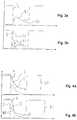
- FIG. 3 ais a schematic diagram view showing an initial increase in the expiratory gas flow to avoid air trapping
- FIG. 3 bis a schematic diagram view showing an initial increase in the expiratory gas flow to avoid air trapping
- FIG. 4 ais a schematic diagram view showing a brief reduction of the PEEP
- FIG. 4 bis a schematic diagram view showing a brief reduction of the PEEP
- FIG. 5 ais a schematic diagram view showing a brief increase in the PEEP.
- FIG. 5 bis a schematic diagram view showing a brief increase in the PEEP.
- a ventilatoris designated in its entirety by the reference number 1 in FIG. 1 . It has a blower unit 10 with a fan 17 , which blower unit 10 is connected to a patient 2 via a user interface 16 .
- the user interface 16comprises a tube 13 , which is connected to a gas flow-measuring unit 14 , a Y-piece 15 , which is connected with one end to the gas flow-measuring unit 14 , and an exhalation valve 11 , which is connected to a second end of the Y-piece 15 .
- the last end of the Y-piece 15is fluid-communicatingly connected to a fan 17 of the blower unit 10 via a tube 12 .
- the user interface 16may be configured as a mask, as a nasal mask or also in another form, the user interface 16 always comprising an exhalation valve 11 .
- the ventilator 1further comprises a control device 18 , which transmits control signals to the exhalation valve 11 and to the fan 17 , as well as received measured signals from the gas flow-measuring unit 14 .
- the control device 18determines the expiratory gas flow on the basis of the measured data of the gas flow-measuring unit 14 .
- the control device 18controls the exhalation valve 11 during the phase of exhalation on the basis of the data of the gas flow-measuring unit 14 . Further, the control device 18 can actuate the exhalation valve 11 during a phase of exhalation with predefined maneuvers and then detect the change in the expiratory gas flow in the same phase of exhalation by means of the gas flow-measuring unit 14 .
- the control device 18comprises for this a change module 182 , which transmits change signals to the exhalation valve 11 .
- the change signalscause the exhalation valve 11 to set a PEEP deviating from a basic PEEP value 31 .
- the control device 18has a determination module 180 .
- the determination module 180is further configured to receive pressure signals from pressure sensor 19 .
- the determination module 180can determine additional parameters, e.g., the exhalation resistance, from the transmitted signals.
- a plurality of exhalation parametersare plotted over time in FIG. 2 a .
- the rectangular curve drawn in solid linepresents the exhalation valve pressure 3 over time.
- a high exhalation valve pressure 3shows a phase of inhalation, while a low exhalation valve pressure 3 indicates a phase of exhalation.
- the exhalation valve pressure 3is not 0 mbar during the phase of exhalation, but it amounts to a few mbar, which corresponds to the PEEP.
- the difference between the maximum and the minimum of the exhalation valve pressure 3is the first pressure difference 30 .
- the minimum of the exhalation valve pressure 3 in FIG. 2 acorresponds to the basic PEEP value 31 .
- the airway pressure 4which becomes established in the lungs of the patient 2 , is represented by the broken line.
- the airway pressure 4drops markedly more slowly than the exhalation valve pressure 3 from a maximum during the phase of exhalation to the PEEP.
- a first expiratory gas flow 5which designates the gas flow during the phase of exhalation, is shown by the dash-dot line.
- the first expiratory gas flow 5drops to 0 L/sec at the end of the phase of exhalation from a maximum at the beginning of the phase of exhalation.
- the exhalation valve pressure 3is controlled by the control unit 18 .
- the first expiratory gas flow 5is determined by the gas flow-measuring unit 14 .
- FIG. 2 bshows the first expiratory gas flow 5 as a reference in order to illustrate the differences from the second expiratory gas flow 50 described below.
- the basic PEEP value 31is drawn as a double dash-dot line to illustrate the differences.
- the exhalation valve pressure 3is reduced by a PEEP pressure reduction 6 at the beginning of the phase of exhalation.
- the expiratory gas flowis increased, as is indicated by the broken line, which shows the second expiratory gas flow 50 .
- the airway pressure 4now drops more rapidly than in FIG. 2 b .
- the exhalation valve pressure 3is raised again to the basic PEEP valve 31 .
- the drop of the airway pressure 4takes place more slowly than before beginning from the rise, because the expiratory gas flow is reduced by the rise in the exhalation valve pressure 3 .
- the airway resistance of the systemcomprising the ventilator 1 and the patient 2 can be calculated. Further, the compliance of the system can be calculated.
- the PEEPcan be set at the exhalation valve 11 accurately by means of the calculated values by the control device 18 during the same phase of exhalation.
- the pressure at the exhalation valve 11may be lower in this case than the desired PEEP, because the PEEP is calculated from the pressure at the exhalation valve 11 in combination with the pressure that is calculated from the expiratory gas flow multiplied by the exhalation resistance.
- the averaged exhalation resistance of the system from a plurality of breathscan be used as a basis for the calculation of the optimal pressure at the exhalation valve 11 in order to suppress dynamic changes between different breaths.
- the exhalation resistancecan also be estimated with sufficient accuracy in case of known components.
- the exhalation resistanceshould be estimated rather as too low than as too high in order not to risk a PEEP that is too low for the patient 2 .
- FIG. 3 ashows a situation in which the expiatory gas flow is not sufficient during the phase of exhalation to allow the entire breath volume to flow out of the lungs during the phase of exhalation.
- the phase of inhalationthus starts too early.
- the expiratory gas flowis designated here as the third expiratory gas flow 51 , which is relatively low and has a flat course compared to the first expiratory gas flow 5 shown in FIG. 2 a .
- An air trapping indication 52can be seen at the end of the phase of exhalation.
- the air trapping indication 52arises from the fact that the expiratory gas flow 51 does not drop to 0 L/sec at the end of the phase of exhalation but remains at a value greater than 0 L/sec. This indicates that the PEEP was estimated to be too high or the exhalation resistance is higher than assumed.
- Airremains in the lungs of the patient 2 after each phase of exhalation due to the air trapping.
- the same volumeis introduced into the lungs of the patient 2 during each phase of inhalation. Due to the air trapping, there remains an offset, which increases with each breath, after each phase of exhalation, so that the residual volume in the lungs increases with each phase of inhalation.
- FIG. 3 bshows a maneuver that corresponds to the maneuver in FIG. 2 b , and air trapping is avoided according to FIG. 3 b .
- the exhalation valve pressure 3is reduced for this to far below the desired PEEP at the beginning of the phase of exhalation. This is represented by the PEEP pressure drop 6 .
- the third expiratory gas flow 51which is markedly lower at the beginning of the phase of exhalation than the fourth expiratory gas flow 53 , is additionally shown for comparison. Further, the fourth expiratory gas flow 53 drops markedly below the first expiratory gas flow 51 at the end of the phase of exhalation.
- the exhalation valve pressure 3is again raised to the basic PEEP value 31 .
- the fourth expiratory gas flow 53drops to 0 L/sec at the end of the phase of exhalation, so that the lungs were completely freed of the breath volume. Air trapping is avoided hereby.
- FIG. 4 ashows a reference curve, which is used to illustrate the differences of the curves shown in FIG. 4 b.
- FIG. 4 bshows an embodiment of the method with which the differential value can be calculated for the exhalation resistance and the compliance at the tidal volume or state of distension of the lungs that are present at this time.
- the exhalation valve pressure 3is briefly reduced for this within a pressure reduction period 35 .
- the pressure reduction period 35is very short relative to the entire phase of exhalation. It may be in the range of 10-30 msec.
- the first expiratory gas flow 5is briefly increased with an expiratory gas flow increase 57 .
- the pressure at the exhalation valve 11corresponds to the product of the expiratory gas flow times the exhalation resistance at this point of the tidal volume.
- the particular exhalation resistancecan therefore be determined in this manner at different points of the tidal volume, i.e., for different states of distension of the lungs. Further, the compliance can thus be determined as a function of the tidal volume of the lungs.
- FIG. 5 ashows a reference diagram
- FIG. 5 bshows an arbitrary brief interruption of the first expiratory gas flow 5 , which is due to the exhalation valve pressure 3 being briefly raised to the inhalation pressure within a pressure increase period 34 .
- An airway pressure increase 40now becomes established based on the briefly reduced expiratory gas flow 56 .
- the compliance of the lungscan be calculated based on the rise (in airway pressure 40 ) during the measurement period 42 and by means of the airway pressure difference 41 .
- This methodis suitable above all for a measurement of the compliance during spontaneous breathing or assisted ventilation. It was impossible or difficult to determine the compliance during spontaneous breathing or assisted ventilation before.
Landscapes
- Health & Medical Sciences (AREA)
- Life Sciences & Earth Sciences (AREA)
- Pulmonology (AREA)
- Veterinary Medicine (AREA)
- General Health & Medical Sciences (AREA)
- Animal Behavior & Ethology (AREA)
- Public Health (AREA)
- Engineering & Computer Science (AREA)
- Biomedical Technology (AREA)
- Heart & Thoracic Surgery (AREA)
- Anesthesiology (AREA)
- Emergency Medicine (AREA)
- Hematology (AREA)
- Biophysics (AREA)
- Surgery (AREA)
- Molecular Biology (AREA)
- Medical Informatics (AREA)
- Pathology (AREA)
- Physics & Mathematics (AREA)
- Physiology (AREA)
- Measurement Of The Respiration, Hearing Ability, Form, And Blood Characteristics Of Living Organisms (AREA)
- Respiratory Apparatuses And Protective Means (AREA)
Abstract
Description
Claims (6)
Applications Claiming Priority (3)
| Application Number | Priority Date | Filing Date | Title |
|---|---|---|---|
| DE102016012824.0ADE102016012824A1 (en) | 2016-10-25 | 2016-10-25 | Method and apparatus for adaptively controlling positive end-expiratory pressure (PEEP) |
| DE102016012824 | 2016-10-25 | ||
| DE102016012824.0 | 2016-10-25 |
Publications (2)
| Publication Number | Publication Date |
|---|---|
| US20180110957A1 US20180110957A1 (en) | 2018-04-26 |
| US10898671B2true US10898671B2 (en) | 2021-01-26 |
Family
ID=61865776
Family Applications (1)
| Application Number | Title | Priority Date | Filing Date |
|---|---|---|---|
| US15/793,201Active2038-10-26US10898671B2 (en) | 2016-10-25 | 2017-10-25 | Method and device for the adaptive regulation of a positive end-expiratory pressure (PEEP) |
Country Status (3)
| Country | Link |
|---|---|
| US (1) | US10898671B2 (en) |
| CN (1) | CN107970510B (en) |
| DE (1) | DE102016012824A1 (en) |
Families Citing this family (10)
| Publication number | Priority date | Publication date | Assignee | Title |
|---|---|---|---|---|
| DE102017008791B4 (en) | 2017-09-20 | 2025-10-02 | Drägerwerk AG & Co. KGaA | Ventilator with a control unit |
| EP3884981B1 (en)* | 2018-11-23 | 2024-07-10 | Shenzhen Mindray Bio-Medical Electronics Co., Ltd. | Positive end expiratory pressure determining apparatus |
| CN110237375B (en)* | 2019-04-18 | 2022-07-08 | 北京雅果科技有限公司 | Breathing machine and negative pressure sputum excretion machine |
| DE102019003643A1 (en)* | 2019-05-24 | 2020-11-26 | Drägerwerk AG & Co. KGaA | Arrangement with an inspiration valve for a ventilation system |
| CN110522451B (en)* | 2019-08-13 | 2022-11-08 | 深圳市美好创亿医疗科技股份有限公司 | Method and system for measuring dispersion amount of CO in multi-component gas |
| GB202005249D0 (en)* | 2020-04-08 | 2020-05-20 | Imp College Innovations Ltd | Control method for medical ventilators |
| US12292429B2 (en) | 2020-06-29 | 2025-05-06 | Dräger Safety AG & Co. KGaA | Monitoring system |
| DE102021111431A1 (en) | 2020-06-29 | 2021-12-30 | Dräger Safety AG & Co. KGaA | Surveillance system |
| CN113288113B (en)* | 2021-05-27 | 2023-02-28 | 湖南城市学院 | Method for online measuring and calculating respiratory tract air resistance and compliance of noninvasive positive pressure respirator |
| CN114146282B (en)* | 2021-12-08 | 2022-12-09 | 山东大学 | End-expiratory positive pressure valve for portable respirator and control method thereof |
Citations (20)
| Publication number | Priority date | Publication date | Assignee | Title |
|---|---|---|---|---|
| US5063925A (en)* | 1988-07-07 | 1991-11-12 | Dragerwerk Aktiengesellschaft | Controllable expiration valve arrangement for a ventilating apparatus |
| US5357946A (en) | 1992-10-19 | 1994-10-25 | Sherwood Medical Company | Ventilator manifold with accessory access port and adaptors therefore |
| US5575283A (en) | 1994-02-14 | 1996-11-19 | Siemens-Elema Ab | Device for determining an opening pressure in the lungs |
| US5915381A (en) | 1995-12-01 | 1999-06-29 | Siemens Elema Ab | Breathing apparatus and method for controlling same |
| US6257234B1 (en)* | 1998-08-21 | 2001-07-10 | Respironics, Inc. | Apparatus and method for determining respiratory mechanics of a patient and for controlling a ventilator based thereon |
| US6510851B2 (en) | 2000-06-29 | 2003-01-28 | Siemens-Elema Ab | Method and arrangement for evaluating effective flow resistance of patient breathing circuit |
| US6564798B1 (en)* | 1999-07-15 | 2003-05-20 | Siemens Elema Ab | Method and computer software product for controlling an expiratory valve in a ventilator |
| US20030168066A1 (en)* | 2002-03-05 | 2003-09-11 | Siemens Elema Ab | Mechanical breathing aid with adaptive expiration control |
| US20090114223A1 (en)* | 2007-11-01 | 2009-05-07 | Intermed-Equipamento Medico Hospitalar Ltda. | Method and system to control mechanical lung ventilation |
| US20100307499A1 (en)* | 2009-06-05 | 2010-12-09 | Drager Medical Ag & Co. Kg | Respirator with automatically controlled pressure-assist respiration |
| CN102369036A (en) | 2009-03-27 | 2012-03-07 | 马奎特紧急护理公司 | PEEP regulation of breathing equipment |
| US20120330177A1 (en)* | 2009-12-28 | 2012-12-27 | Nawar Nazar Yousif Al-Rawas | System and Method for Assessing Real Time Pulmonary Mechanics |
| DE102011106406A1 (en) | 2011-07-02 | 2013-01-03 | Dräger Medical GmbH | Method for controlling end-expiratory pressure in a ventilator circuit |
| US20130284177A1 (en)* | 2012-04-30 | 2013-10-31 | Nellcor Puritan Bennett Llc | Minimizing imposed expiratory resistance of mechanical ventilator by optimizing exhalation valve control |
| US20150045687A1 (en)* | 2013-08-07 | 2015-02-12 | Covidien Lp | Detection of expiratory airflow limitation in ventilated patient |
| US20150083135A1 (en)* | 2012-12-26 | 2015-03-26 | Beijing Aeonmed Co., Ltd. | Ventilator turbine-based volume-controlled ventilation method |
| US20150217069A1 (en)* | 2012-09-04 | 2015-08-06 | Hamilton Medical Ag | System for automated adjustment of a pressure set by a ventilation device |
| CN105899249A (en) | 2013-10-29 | 2016-08-24 | 通用电气公司 | Method and arrangement for determining a vetilation need specific for a patient |
| US9993604B2 (en)* | 2012-04-27 | 2018-06-12 | Covidien Lp | Methods and systems for an optimized proportional assist ventilation |
| US20190022342A1 (en)* | 2016-03-01 | 2019-01-24 | Ventinova Technologies B.V. | Method and Device for Ventilating a Patient |
Family Cites Families (3)
| Publication number | Priority date | Publication date | Assignee | Title |
|---|---|---|---|---|
| KR20130124172A (en)* | 2010-05-24 | 2013-11-13 | 월풀 에쎄.아. | Suction arrangement for a refrigeration compressor |
| EP2397074B1 (en)* | 2010-06-19 | 2012-10-24 | M Stenqvist AB | A system and computer readable medium for determination of transpulmonary pressure in a patient connected to a breathing apparatus |
| WO2012045560A2 (en)* | 2010-10-08 | 2012-04-12 | Aerocrine Ab | Apparatus for collecting expiratory air |
- 2016
- 2016-10-25DEDE102016012824.0Apatent/DE102016012824A1/enactivePending
- 2017
- 2017-10-25USUS15/793,201patent/US10898671B2/enactiveActive
- 2017-10-25CNCN201711011230.8Apatent/CN107970510B/enactiveActive
Patent Citations (21)
| Publication number | Priority date | Publication date | Assignee | Title |
|---|---|---|---|---|
| US5063925A (en)* | 1988-07-07 | 1991-11-12 | Dragerwerk Aktiengesellschaft | Controllable expiration valve arrangement for a ventilating apparatus |
| US5357946A (en) | 1992-10-19 | 1994-10-25 | Sherwood Medical Company | Ventilator manifold with accessory access port and adaptors therefore |
| US5575283A (en) | 1994-02-14 | 1996-11-19 | Siemens-Elema Ab | Device for determining an opening pressure in the lungs |
| US5915381A (en) | 1995-12-01 | 1999-06-29 | Siemens Elema Ab | Breathing apparatus and method for controlling same |
| US6257234B1 (en)* | 1998-08-21 | 2001-07-10 | Respironics, Inc. | Apparatus and method for determining respiratory mechanics of a patient and for controlling a ventilator based thereon |
| US6564798B1 (en)* | 1999-07-15 | 2003-05-20 | Siemens Elema Ab | Method and computer software product for controlling an expiratory valve in a ventilator |
| US6510851B2 (en) | 2000-06-29 | 2003-01-28 | Siemens-Elema Ab | Method and arrangement for evaluating effective flow resistance of patient breathing circuit |
| US20030168066A1 (en)* | 2002-03-05 | 2003-09-11 | Siemens Elema Ab | Mechanical breathing aid with adaptive expiration control |
| US20090114223A1 (en)* | 2007-11-01 | 2009-05-07 | Intermed-Equipamento Medico Hospitalar Ltda. | Method and system to control mechanical lung ventilation |
| CN102369036A (en) | 2009-03-27 | 2012-03-07 | 马奎特紧急护理公司 | PEEP regulation of breathing equipment |
| US20120167884A1 (en)* | 2009-03-27 | 2012-07-05 | Erik Cardelius | Peep regulation for a breathing apparatus |
| US20100307499A1 (en)* | 2009-06-05 | 2010-12-09 | Drager Medical Ag & Co. Kg | Respirator with automatically controlled pressure-assist respiration |
| US20120330177A1 (en)* | 2009-12-28 | 2012-12-27 | Nawar Nazar Yousif Al-Rawas | System and Method for Assessing Real Time Pulmonary Mechanics |
| DE102011106406A1 (en) | 2011-07-02 | 2013-01-03 | Dräger Medical GmbH | Method for controlling end-expiratory pressure in a ventilator circuit |
| US9993604B2 (en)* | 2012-04-27 | 2018-06-12 | Covidien Lp | Methods and systems for an optimized proportional assist ventilation |
| US20130284177A1 (en)* | 2012-04-30 | 2013-10-31 | Nellcor Puritan Bennett Llc | Minimizing imposed expiratory resistance of mechanical ventilator by optimizing exhalation valve control |
| US20150217069A1 (en)* | 2012-09-04 | 2015-08-06 | Hamilton Medical Ag | System for automated adjustment of a pressure set by a ventilation device |
| US20150083135A1 (en)* | 2012-12-26 | 2015-03-26 | Beijing Aeonmed Co., Ltd. | Ventilator turbine-based volume-controlled ventilation method |
| US20150045687A1 (en)* | 2013-08-07 | 2015-02-12 | Covidien Lp | Detection of expiratory airflow limitation in ventilated patient |
| CN105899249A (en) | 2013-10-29 | 2016-08-24 | 通用电气公司 | Method and arrangement for determining a vetilation need specific for a patient |
| US20190022342A1 (en)* | 2016-03-01 | 2019-01-24 | Ventinova Technologies B.V. | Method and Device for Ventilating a Patient |
Also Published As
| Publication number | Publication date |
|---|---|
| CN107970510A (en) | 2018-05-01 |
| US20180110957A1 (en) | 2018-04-26 |
| CN107970510B (en) | 2020-08-11 |
| DE102016012824A1 (en) | 2018-04-26 |
Similar Documents
| Publication | Publication Date | Title |
|---|---|---|
| US10898671B2 (en) | Method and device for the adaptive regulation of a positive end-expiratory pressure (PEEP) | |
| US11497869B2 (en) | Methods and systems for adaptive base flow | |
| EP3525857B1 (en) | Systems for drive pressure spontaneous ventilation | |
| US8844526B2 (en) | Methods and systems for triggering with unknown base flow | |
| US7984712B2 (en) | Patient circuit disconnect system for a ventilator and method of detecting patient circuit disconnect | |
| US10765822B2 (en) | Endotracheal tube extubation detection | |
| US9295796B2 (en) | Breathing system with flow estimation | |
| US9925346B2 (en) | Systems and methods for ventilation with unknown exhalation flow | |
| US11752285B2 (en) | System and method for accurate estimation of intentional and unintentional leaks in flow generation systems | |
| CN101467880A (en) | Method for improving tidal volume control and detection accuracy by introducing R value for calculation | |
| CN109316655B (en) | Air supply mask system | |
| US20230364369A1 (en) | Systems and methods for automatic cycling or cycling detection | |
| JP2020535909A (en) | Ventilator with automatic detection of flow sensor error for spontaneous respiration | |
| US20190083726A1 (en) | Process for operating a ventilator and ventilator operating according to the process | |
| EP2571423A1 (en) | System and method for estimating upper airway resistance and lung compliance employing induced central apneas | |
| CN103182121A (en) | Pressure trigger control method for breathing machine | |
| EP3655965B1 (en) | Ventilator gas delivery initiation via a virtual pressure triggering mechanism | |
| US9308338B2 (en) | Detection of dynamic hyperinflation in spontaneously breathing mechanically ventilated patients | |
| CN117731900B (en) | Ventilation monitoring system and method |
Legal Events
| Date | Code | Title | Description |
|---|---|---|---|
| FEPP | Fee payment procedure | Free format text:ENTITY STATUS SET TO UNDISCOUNTED (ORIGINAL EVENT CODE: BIG.); ENTITY STATUS OF PATENT OWNER: LARGE ENTITY | |
| AS | Assignment | Owner name:DRAEGERWERK AG & CO. KGAA, GERMANY Free format text:ASSIGNMENT OF ASSIGNORS INTEREST;ASSIGNORS:HANSMANN, HANS-ULLRICH;HILTAWSKY, KARSTEN, DR.;SIGNING DATES FROM 20171019 TO 20171106;REEL/FRAME:044398/0725 | |
| STPP | Information on status: patent application and granting procedure in general | Free format text:DOCKETED NEW CASE - READY FOR EXAMINATION | |
| STPP | Information on status: patent application and granting procedure in general | Free format text:NON FINAL ACTION MAILED | |
| STPP | Information on status: patent application and granting procedure in general | Free format text:FINAL REJECTION MAILED | |
| STPP | Information on status: patent application and granting procedure in general | Free format text:ADVISORY ACTION MAILED | |
| STPP | Information on status: patent application and granting procedure in general | Free format text:RESPONSE AFTER FINAL ACTION FORWARDED TO EXAMINER | |
| STPP | Information on status: patent application and granting procedure in general | Free format text:PUBLICATIONS -- ISSUE FEE PAYMENT VERIFIED | |
| STCF | Information on status: patent grant | Free format text:PATENTED CASE | |
| MAFP | Maintenance fee payment | Free format text:PAYMENT OF MAINTENANCE FEE, 4TH YEAR, LARGE ENTITY (ORIGINAL EVENT CODE: M1551); ENTITY STATUS OF PATENT OWNER: LARGE ENTITY Year of fee payment:4 |