US10898603B2 - System and apparatus thereof for destroying pathogens associated with footwear - Google Patents
System and apparatus thereof for destroying pathogens associated with footwearDownload PDFInfo
- Publication number
- US10898603B2 US10898603B2US15/626,615US201715626615AUS10898603B2US 10898603 B2US10898603 B2US 10898603B2US 201715626615 AUS201715626615 AUS 201715626615AUS 10898603 B2US10898603 B2US 10898603B2
- Authority
- US
- United States
- Prior art keywords
- leds
- led
- platform
- ultraviolet light
- disposed
- Prior art date
- Legal status (The legal status is an assumption and is not a legal conclusion. Google has not performed a legal analysis and makes no representation as to the accuracy of the status listed.)
- Expired - Fee Related
Links
Images


Classifications
- A—HUMAN NECESSITIES
- A61—MEDICAL OR VETERINARY SCIENCE; HYGIENE
- A61L—METHODS OR APPARATUS FOR STERILISING MATERIALS OR OBJECTS IN GENERAL; DISINFECTION, STERILISATION OR DEODORISATION OF AIR; CHEMICAL ASPECTS OF BANDAGES, DRESSINGS, ABSORBENT PADS OR SURGICAL ARTICLES; MATERIALS FOR BANDAGES, DRESSINGS, ABSORBENT PADS OR SURGICAL ARTICLES
- A61L2/00—Methods or apparatus for disinfecting or sterilising materials or objects other than foodstuffs or contact lenses; Accessories therefor
- A61L2/02—Methods or apparatus for disinfecting or sterilising materials or objects other than foodstuffs or contact lenses; Accessories therefor using physical phenomena
- A61L2/08—Radiation
- A61L2/10—Ultraviolet radiation
- H—ELECTRICITY
- H05—ELECTRIC TECHNIQUES NOT OTHERWISE PROVIDED FOR
- H05B—ELECTRIC HEATING; ELECTRIC LIGHT SOURCES NOT OTHERWISE PROVIDED FOR; CIRCUIT ARRANGEMENTS FOR ELECTRIC LIGHT SOURCES, IN GENERAL
- H05B45/00—Circuit arrangements for operating light-emitting diodes [LED]
- H05B45/20—Controlling the colour of the light
- H05B45/22—Controlling the colour of the light using optical feedback
- A—HUMAN NECESSITIES
- A47—FURNITURE; DOMESTIC ARTICLES OR APPLIANCES; COFFEE MILLS; SPICE MILLS; SUCTION CLEANERS IN GENERAL
- A47L—DOMESTIC WASHING OR CLEANING; SUCTION CLEANERS IN GENERAL
- A47L11/00—Machines for cleaning floors, carpets, furniture, walls, or wall coverings
- A47L11/40—Parts or details of machines not provided for in groups A47L11/02 - A47L11/38, or not restricted to one of these groups, e.g. handles, arrangements of switches, skirts, buffers, levers
- A47L11/4036—Parts or details of the surface treating tools
- A47L11/405—Machines using UV-lamps, IR-lamps, ultrasound or plasma cleaning
- A—HUMAN NECESSITIES
- A47—FURNITURE; DOMESTIC ARTICLES OR APPLIANCES; COFFEE MILLS; SPICE MILLS; SUCTION CLEANERS IN GENERAL
- A47L—DOMESTIC WASHING OR CLEANING; SUCTION CLEANERS IN GENERAL
- A47L23/00—Cleaning footwear
- A47L23/02—Shoe-cleaning machines, with or without applicators for shoe polish
- A—HUMAN NECESSITIES
- A61—MEDICAL OR VETERINARY SCIENCE; HYGIENE
- A61L—METHODS OR APPARATUS FOR STERILISING MATERIALS OR OBJECTS IN GENERAL; DISINFECTION, STERILISATION OR DEODORISATION OF AIR; CHEMICAL ASPECTS OF BANDAGES, DRESSINGS, ABSORBENT PADS OR SURGICAL ARTICLES; MATERIALS FOR BANDAGES, DRESSINGS, ABSORBENT PADS OR SURGICAL ARTICLES
- A61L2/00—Methods or apparatus for disinfecting or sterilising materials or objects other than foodstuffs or contact lenses; Accessories therefor
- A61L2/0005—Methods or apparatus for disinfecting or sterilising materials or objects other than foodstuffs or contact lenses; Accessories therefor for pharmaceuticals, biologicals or living parts
- A61L2/0011—Methods or apparatus for disinfecting or sterilising materials or objects other than foodstuffs or contact lenses; Accessories therefor for pharmaceuticals, biologicals or living parts using physical methods
- A61L2/0029—Radiation
- A61L2/0047—Ultraviolet radiation
- A—HUMAN NECESSITIES
- A61—MEDICAL OR VETERINARY SCIENCE; HYGIENE
- A61L—METHODS OR APPARATUS FOR STERILISING MATERIALS OR OBJECTS IN GENERAL; DISINFECTION, STERILISATION OR DEODORISATION OF AIR; CHEMICAL ASPECTS OF BANDAGES, DRESSINGS, ABSORBENT PADS OR SURGICAL ARTICLES; MATERIALS FOR BANDAGES, DRESSINGS, ABSORBENT PADS OR SURGICAL ARTICLES
- A61L2/00—Methods or apparatus for disinfecting or sterilising materials or objects other than foodstuffs or contact lenses; Accessories therefor
- A61L2/24—Apparatus using programmed or automatic operation
- A—HUMAN NECESSITIES
- A61—MEDICAL OR VETERINARY SCIENCE; HYGIENE
- A61L—METHODS OR APPARATUS FOR STERILISING MATERIALS OR OBJECTS IN GENERAL; DISINFECTION, STERILISATION OR DEODORISATION OF AIR; CHEMICAL ASPECTS OF BANDAGES, DRESSINGS, ABSORBENT PADS OR SURGICAL ARTICLES; MATERIALS FOR BANDAGES, DRESSINGS, ABSORBENT PADS OR SURGICAL ARTICLES
- A61L9/00—Disinfection, sterilisation or deodorisation of air
- A61L9/015—Disinfection, sterilisation or deodorisation of air using gaseous or vaporous substances, e.g. ozone
- E—FIXED CONSTRUCTIONS
- E04—BUILDING
- E04F—FINISHING WORK ON BUILDINGS, e.g. STAIRS, FLOORS
- E04F15/00—Flooring
- E04F15/02—Flooring or floor layers composed of a number of similar elements
- E04F15/024—Sectional false floors, e.g. computer floors
- E04F15/02405—Floor panels
- H—ELECTRICITY
- H05—ELECTRIC TECHNIQUES NOT OTHERWISE PROVIDED FOR
- H05B—ELECTRIC HEATING; ELECTRIC LIGHT SOURCES NOT OTHERWISE PROVIDED FOR; CIRCUIT ARRANGEMENTS FOR ELECTRIC LIGHT SOURCES, IN GENERAL
- H05B47/00—Circuit arrangements for operating light sources in general, i.e. where the type of light source is not relevant
- H05B47/10—Controlling the light source
- H05B47/105—Controlling the light source in response to determined parameters
- H05B47/11—Controlling the light source in response to determined parameters by determining the brightness or colour temperature of ambient light
- H—ELECTRICITY
- H05—ELECTRIC TECHNIQUES NOT OTHERWISE PROVIDED FOR
- H05B—ELECTRIC HEATING; ELECTRIC LIGHT SOURCES NOT OTHERWISE PROVIDED FOR; CIRCUIT ARRANGEMENTS FOR ELECTRIC LIGHT SOURCES, IN GENERAL
- H05B47/00—Circuit arrangements for operating light sources in general, i.e. where the type of light source is not relevant
- H05B47/10—Controlling the light source
- H05B47/105—Controlling the light source in response to determined parameters
- H05B47/115—Controlling the light source in response to determined parameters by determining the presence or movement of objects or living beings
- A—HUMAN NECESSITIES
- A61—MEDICAL OR VETERINARY SCIENCE; HYGIENE
- A61L—METHODS OR APPARATUS FOR STERILISING MATERIALS OR OBJECTS IN GENERAL; DISINFECTION, STERILISATION OR DEODORISATION OF AIR; CHEMICAL ASPECTS OF BANDAGES, DRESSINGS, ABSORBENT PADS OR SURGICAL ARTICLES; MATERIALS FOR BANDAGES, DRESSINGS, ABSORBENT PADS OR SURGICAL ARTICLES
- A61L2202/00—Aspects relating to methods or apparatus for disinfecting or sterilising materials or objects
- A61L2202/10—Apparatus features
- A61L2202/14—Means for controlling sterilisation processes, data processing, presentation and storage means, e.g. sensors, controllers, programs
- A—HUMAN NECESSITIES
- A61—MEDICAL OR VETERINARY SCIENCE; HYGIENE
- A61L—METHODS OR APPARATUS FOR STERILISING MATERIALS OR OBJECTS IN GENERAL; DISINFECTION, STERILISATION OR DEODORISATION OF AIR; CHEMICAL ASPECTS OF BANDAGES, DRESSINGS, ABSORBENT PADS OR SURGICAL ARTICLES; MATERIALS FOR BANDAGES, DRESSINGS, ABSORBENT PADS OR SURGICAL ARTICLES
- A61L2202/00—Aspects relating to methods or apparatus for disinfecting or sterilising materials or objects
- A61L2202/10—Apparatus features
- A61L2202/15—Biocide distribution means, e.g. nozzles, pumps, manifolds, fans, baffles, sprayers
- Y—GENERAL TAGGING OF NEW TECHNOLOGICAL DEVELOPMENTS; GENERAL TAGGING OF CROSS-SECTIONAL TECHNOLOGIES SPANNING OVER SEVERAL SECTIONS OF THE IPC; TECHNICAL SUBJECTS COVERED BY FORMER USPC CROSS-REFERENCE ART COLLECTIONS [XRACs] AND DIGESTS
- Y02—TECHNOLOGIES OR APPLICATIONS FOR MITIGATION OR ADAPTATION AGAINST CLIMATE CHANGE
- Y02B—CLIMATE CHANGE MITIGATION TECHNOLOGIES RELATED TO BUILDINGS, e.g. HOUSING, HOUSE APPLIANCES OR RELATED END-USER APPLICATIONS
- Y02B20/00—Energy efficient lighting technologies, e.g. halogen lamps or gas discharge lamps
- Y02B20/40—Control techniques providing energy savings, e.g. smart controller or presence detection
Definitions
- the present disclosurerelates to devices for cleaning footwear. More specifically, the present disclosure relates to an apparatus that uses ultraviolet light to destroy or inhibit the growth of surface pathogens, such as, for example, virus, bacteria, mold, spore, and fungi, and/or to reduce chemical contaminants.
- surface pathogenssuch as, for example, virus, bacteria, mold, spore, and fungi
- the soles of people's footwearare a primary vehicle for pathogens entering homes and healthcare facilities.
- the pathogenscan cause sickness, disease, and possible death.
- Door matsthe primary means for cleaning shoe bottoms, remove dirt but not pathogens, and can quickly become an incubator for germs.
- Other solutionssuch as liquid dips are not practical for high traffic areas and require frequent maintenance to stay effective.
- Disposable booties or shoe coversare used in professional environments, but do not work well in public areas, as people tend to be self-conscience about wearing them, and there are safety concerns over people tripping while wearing such covers.
- UV-Cshort-wavelength ultraviolet
- an apparatus for destroying pathogensincludes a platform and an LED matrix panel.
- the platformhas a portion configured to permit passage of ultraviolet light therethrough.
- the LED matrix panelis disposed below the portion of the platform and includes a grid defining a plurality of cells, and a plurality of discreetly-controlled, ultraviolet light LEDs (UV LEDs) that selectively emit ultraviolet light.
- Each UV LEDis associated with one of the cells such that the cells direct the ultraviolet light emitted by the UV LEDs upwardly through the portion of the platform to sanitize an object supported on the portion of the platform.
- the apparatusmay further include a plurality of visible light emitting LEDs (V LEDs) each electrically linked to a corresponding UV LED.
- V LEDsvisible light emitting LEDs
- Each V LEDmay be disposed adjacent its corresponding UV LED and may be configured to emit visible light concurrently with the emission of ultraviolet light from the corresponding UV LED.
- the apparatusmay further include a processor in communication with the UV LEDs and the V LEDS.
- the processormay be configured to selectively activate the V LEDs to emit a first color of visible light upon the corresponding UV LED being in an ON state, and a second color of visible light upon the corresponding UV LED being in an OFF state.
- the UV LEDsmay be further configured as photodiodes such that the UV LEDs sense a change in light upon an object being disposed on the portion of the platform to activate the UV LEDs.
- the apparatusmay further include a pressure sensor coupled to the platform and in communication with the UV LEDs.
- the UV LEDsmay be configured to be activated upon the pressure sensor sensing a threshold force.
- the apparatusmay further include a plurality of sensors.
- the sensorsmay be disposed within a respective one of the cells.
- a first UV LEDmay be activated in response to a first sensor sensing an object on the portion of the platform.
- the first UV LED and the first sensormay be disposed within the same cell.
- the first sensormay sense the object only when the object is disposed directly above the first sensor.
- the sensorsmay be infrared sensors and/or photodiodes.
- the gridmay include a plurality of spaced apart longitudinal walls and a plurality of spaced apart transverse walls in a crisscrossing arrangement with the longitudinal walls.
- the longitudinal and transverse wallsmay together define the cells.
- the platformmay include a frame and a pair of plates.
- the framemay define a pair of openings and may be fabricated from a material that prevents the transmission of ultraviolet light.
- the platesmay be fabricated from quartz and may be disposed within a respective opening. The quartz permits the transmission of ultraviolet light therethrough.
- each of the platesmay define an outer periphery that is in abutment with a respective inner side wall of the frame.
- the outer periphery of each of the platesmay be sealed to the respective inner side walls of the frame.
- the apparatusmay further include a housing assembly in which the LED matrix panel is disposed.
- the LED matrix panelmay be thermally coupled to an inner surface of the housing assembly.
- the LED matrix panelmay include a printed circuit board on which the UV LEDS are situated.
- the printed circuit boardmay be thermally coupled to a bottom housing of the housing assembly.
- a footwear-sanitizing systemin another aspect of the present disclosure, includes a user interface to be mounted to a wall, and an apparatus to be disposed on a floor.
- the user interfaceis configured to display a progress of a sanitization process.
- the apparatusis in communication with the user interface and includes a platform and an LED matrix panel.
- the platformhas a portion configured to permit passage of ultraviolet light therethrough.
- the LED matrix panelis disposed below the portion of the platform and includes a grid and a plurality of discreetly-controlled, ultraviolet light LEDs (UV LEDs) that selectively emit ultraviolet light.
- the griddefines a plurality of cells and each UV LED is associated with one of the cells such that the cells direct the ultraviolet light emitted by the UV LEDs upwardly through the portion of the platform to sanitize an object supported on the portion of the platform.
- the systemmay further include a processor in communication with each of the UV LEDs, the V LEDS, and the user interface.
- the processormay be configured to selectively activate the V LEDs of the apparatus and lights of the user interface to emit a first color of visible light upon the corresponding UV LED being in an ON state, and a second color of visible light upon the corresponding UV LED being in an OFF state.
- a method of installing a footwear-sanitizing systemincludes mounting a user interface to a wall of a room, positioning the apparatus on a floor of the room, and connecting the user interface and the UV LEDS of the apparatus to an external power source.
- parallel and perpendicularare understood to include relative configurations that are substantially parallel and substantially perpendicular up to about + or ⁇ 10 degrees from true parallel and true perpendicular.
- FIG. 1is a perspective view a footwear-sanitizing system including a footwear sanitizer and a user interface each installed in an operating room in accordance with the principles of the present disclosure
- FIG. 2is a top view of the footwear sanitizer of FIG. 1 ;
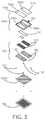
- FIG. 3is a perspective view, with parts separated, of the footwear sanitizer of FIG. 2 ;
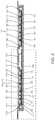
- FIG. 4is a cross-section, taken along line 4 - 4 of FIG. 2 , of the footwear sanitizer
- FIG. 5is an enlarged view of a portion of the footwear sanitizer indicated as detail 5 in FIG. 4 ;
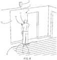
- FIG. 6is a perspective view of the footwear-sanitizing system of FIG. 1 , illustrating a person standing on the footwear sanitizer and interacting with the user interface;
- FIG. 7is a perspective view of the footwear-sanitizing system of FIG. 1 , illustrating the footwear sanitizer thereof installed into a floor of the operating room;
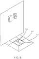
- FIG. 8is a perspective view of another embodiment of a footwear-sanitizing system including a footwear sanitizer and a user interface each installed in an operating room in accordance with the principles of the present disclosure.
- FIG. 9is a block diagram illustrating the sanitizing system of FIG. 1 installed in a room.
- pathogenincludes, but is not limited to, viruses, bacteria (e.g., Staphylococcus aureus , MRSA, CDIF, VRE, Pseudomonas aeruginosa and E. coli ), molds, spores, fungi, or the like.
- bacteriae.g., Staphylococcus aureus , MRSA, CDIF, VRE, Pseudomonas aeruginosa and E. coli
- moldsspores, fungi, or the like.
- the present disclosureprovides a footwear-sanitizing system that utilizes UV-C light-emitting LEDs to sanitize footwear in a variety of settings including, but not limited to, hospitals, homes, laboratories, etc.
- the UV-C LEDsare smaller than standard UV-C light bulbs allowing for a miniaturization of the overall footwear-sanitizing system.
- the UV LEDsare disposed on a printed circuit board and within individual cells of a grid. Each of the UV LEDs are discreetly controlled such that only those UV LEDs disposed directly below the feet of a user will be activated. Due to the UV LEDs being disposed within cells of the grid, the ultraviolet light is directed upwardly through a platform and onto the bottom of the footwear of the user to destroy pathogens associated therewith.
- a sanitizing systemsuch as a footwear-sanitizing system 10 is illustrated and generally includes an apparatus or footwear sanitizer 100 to be installed in or on a floor “F” of a room, a user interface 20 to be mounted on a vertically-extending wall “W” of the room, and a hand-sanitizing station 22 .
- the user interface 20 and the apparatus 100are in communication with one another and are each externally powered by an external power source via an electrical connection (e.g., wires or wireless connection).
- the apparatus 100is structured to support the weight of a user and to destroy pathogens associated with footwear worn by the user.
- the apparatus 100includes a housing assembly 102 and an LED matrix panel 120 disposed within the housing assembly 102 .
- the housing assembly 102includes a top housing or platform 102 a and a bottom housing 102 b , which when coupled to one another cooperatively define an internal cavity for housing components of the apparatus 100 .
- the housing assembly 102may have a square shape, but in some embodiments may assume any suitable size and shape such as trapezoidal, circular, rectangular, triangular, or the like.
- the platform 102 a of the housing assembly 102includes a frame 104 and a pair of plates 106 a , 106 b supported by the frame 104 .
- the frame 104 and the bottom housing 102 bmay be fabricated from a non-corrosive material that prevents the transmission of ultraviolet light therethrough.
- the frame 104 and the bottom housing 102 bmay be fabricated from any suitable material, such as, for example, various metals, including aluminum.
- the frame 104 of the platform 102 ahas a pair of openings 108 a , 108 b defined through a thickness thereof.
- the openings 108 a , 108 bare dimensioned to securely capture the respective plates 106 a , 106 b therein.
- the frame 104 of the platform 102 ahas a pair of inner side walls 110 a , 110 b , and a pair of ledges 112 a , 112 b extending perpendicularly from the inner side walls 110 a , 110 b and into the respective openings 108 a , 108 b .
- the plates 106 a , 106 bare disposed on the ledges 112 a , 112 b of the frame 104 such that a top surface of each of the plates 106 a , 106 b is flush with a top surface of the frame 104 .
- An outer periphery 114 a , 114 b of each of the plates 106 a , 106 bis in abutting engagement with the respective inner side walls 110 a , 110 b of the frame 104 such that all four sides of the plates 106 a , 106 b are encased by the inner side walls 110 a , 110 b of the frame 104 .
- a sealant “S”may be applied between the inner side walls 110 a , 110 b of the frame 104 and the outer periphery 114 a , 114 b of the plates 106 a , 106 b to form an air-tight seal therebetween.
- the plates 106 a , 106 b of the platform 102 aare elongated and sized to accommodate any size foot of a person standing on the platform 102 a .
- the plates 106 a , 106 bhave a rectangular shape, but it is contemplated that the plates 106 a , 106 b may assume any suitable shape dimensioned to accommodate an entire foot of a person.
- the plates 106 a , 106 bare received within the respective openings 108 a , 108 b of the frame 104 and are formed from a material (e.g., quartz) that permits the passage of UV-C light therethrough while also exhibiting sufficient strength to support the weight of a person.
- the plates 106 a , 106 bmay be fabricated from materials other than quartz, such as fused silica, glass, ruby, or the like.
- the LED matrix panel 120 of the apparatus 100is disposed below and in alignment with the openings 108 a , 108 b of the frame 104 of the platform 102 a , and in turn, the plates 106 a , 106 b of the platform 102 a .
- the LED matrix panel 120includes a plurality of ultraviolet light LEDs (“UV LEDs”) 122 and a grid 124 .
- the UV LEDs 122are discreetly controlled by a processor “P” in communication with a printed circuit board 126 of the LED matrix panel 120 .
- the UV LEDs 122emit short-wavelength ultraviolet radiation (“UV-C light”).
- UV LEDs 122may be configured to emit other wavelengths of ultraviolet light instead of or in addition to UV-C light.
- the UV LEDs 122are arranged on the printed circuit board 126 in a series of longitudinally-extending rows, but in some embodiments the UV LEDs 122 may be arranged on the printed circuit board 126 in any suitable pattern, whether random or defined.
- the UV LEDs 122are powered by a power source (not shown) disposed externally of the apparatus 100 . In some embodiments, the UV LEDs 122 may be replaced with ultraviolet light-emitting bulbs.
- the grid 124 of the LED matrix panel 120is fabricated from a material that prevents transmission of ultraviolet light therethrough, such as, for example, a thermoplastic resin. In some embodiments, inner surfaces of the grid 124 may be coated with a reflective material that reflects ultraviolet light.
- the grid 124includes a plurality of spaced apart longitudinal walls or bars 124 a and a plurality of spaced apart transverse walls or bars 124 b crisscrossing with the longitudinal walls 124 a .
- the longitudinal and transverse walls 124 a , 124 btogether define a plurality of discreet chambers or cells 128 .
- the cells 128are illustrated as having a square configuration, but it is contemplated that the cells 128 may have any suitable shape, such as, for example, circular, triangular, rectangular, oblong, uniform, non-uniform, or the like.
- the grid 124is supported on the printed circuit board 126 such that one UV LED 122 of the plurality of UV LEDs 122 is received in a respective one of the plurality of cells 128 of the grid 124 .
- the UV LEDs 122are partitioned off from adjacent UV LEDs 122 so that ultraviolet light emitted by one UV LED 122 is prevented from escaping laterally into adjacent cells 128 of the grid 124 .
- the longitudinal and transverse walls 124 a , 124 b of the grid 124are perpendicular to a plane defined by the printed circuit board 126 , whereby the ultraviolet light emitted from the UV LEDs 122 is directed or guided perpendicularly upward relative to the printed circuit board 126 . This construction will prevent UV-C light scattering in directions other than directly upward.
- the printed circuit board 126 of the LED matrix panel 120may be directly or indirectly thermally coupled to an inner surface of the housing assembly 102 .
- the printed circuit board 126may be thermally coupled to an inner surface of the bottom housing 102 b of the housing assembly 102 .
- heat generated by the LED matrix panel 120 during usemay be directly transmitted from the printed circuit board 126 and into the thermally conductive housing assembly 102 to facilitate cooling of the LED matrix panel 120 and the overall internal environment of the apparatus 100 .
- the printed circuit board 126 of the LED matrix panel 120is in communication with the processor “P,” which selectively activates particular UV LEDs 122 based on where on the platform 102 a a user's foot is positioned, as will be described.
- the processer “P”may be operably connected to a memory, which may include transitory type memory (e.g., RAM) and/or non-transitory type memory (e.g., flash media, disk media, etc.), collectively referred to as “memory” herein.
- the memorymay store instructions (e.g., software), which when executed on the processor “P” causes one or more footwear sanitizing sequence(s) to be performed by the apparatus 100 .
- the processor “P”transmits control signals to one or more of the described components in electrical communication, either wired or wireless, with the processor “P.”
- the processor “P”may additionally receive sensor signals from the one or more components in communication with the processor “P.”
- the processor “P”may be substituted by using any logic processor (e.g., control circuit) adapted to perform the calculations and/or set of instructions described herein including, but not limited to, field programmable gate arrays, digital signal processor, and combinations thereof.
- the apparatus 100may include a plurality of visible light emitting LEDs (“V LEDs”) 130 arranged on the printed circuit board 126 of the LED matrix panel 120 .
- V LEDs 130may selectively emit a variety of colors of visible light (e.g., blue, green, purple, etc.).
- One V LED 130 of the plurality of UV LEDs 130is received in a respective one of the plurality of cells 128 of the grid 124 , and each V LED 130 is disposed adjacent to and directly electrically linked with one corresponding UV LED 122 .
- a state of the UV LED 122e.g., ON or OFF
- a state of the respective V LED 130e.g., ON, OFF, or a type of color illuminated
- the V LEDs 130may act as status indicators for the UV LEDs 122 by switching on and off concurrently with the UV LEDs 122 .
- the processor “P”may be in communication with the UV LEDs 122 and the V LEDs 130 and may be programmed to selectively activate the V LEDs 130 to emit a particular color(s) based on the status of the associated UV LED 122 .
- the processor “P”may direct the V LEDs 130 associated with the set of UV LEDs 122 to emit a first color (e.g., green) indicating to a user that the UV LEDs 122 are in the OFF state.
- the processor “P”may direct the V LEDs 130 associated with the set of UV LEDs 122 to emit a second color (e.g., purple) indicating to the user that the UV LEDs 122 are in the ON state.
- a second colore.g., purple
- the apparatus 100may include a pressure sensor or sensors 132 for determining when a user is standing on the platform 102 a of the apparatus 100 .
- the pressure sensors 132may be disposed between the frame 104 of the housing assembly 102 and the bottom housing 102 b of the housing assembly 102 .
- the pressure sensors 132are in communication with the UV LEDs 122 and/or the processor “P.”
- the processor “P”may be configured to activate (i.e., switch on) the UV LEDs 122 in response to the pressure sensors 132 sensing a threshold force greater than approximately 40 to 70 lbs. As such, the UV LEDs 122 will remain in the OFF or inactive state until the pressure sensors 132 sense a user standing on the platform 102 a .
- each cell 128 of the LED matrix panel 120may include a pressure sensor 132 , each of which being electrically coupled to the corresponding UV LED 122 and V LED 130 .
- the apparatus 100may include light sensors 134 , such as, for example, infrared sensors or photodiodes.
- One light sensor 134may be disposed in each cell 128 of the grid 124 and may be electrically coupled to the UV LED 122 and V LED 130 disposed within that cell 128 . Due to the light sensors 134 being disposed directly below the plates 106 a , 106 b of the platform 102 a , the light sensors 134 sense a presence or absence of an object (e.g., footwear) on the plates 106 a , 106 b of the platform 102 a .
- an objecte.g., footwear
- the light sensors 134may be configured to sense the presence or absence of an object on the plates 106 a , 106 b of the platform 102 a via sensing a change in infrared heat, a change in visible light, or a change in any other detectable form of electromagnetic radiation.
- the light sensors 134are also in communication with the processor “P” and are configured to signal to the processor “P” when they detect an object on the plates 106 a , 106 b of the platform 102 a .
- the processor “P”is configured to activate only the UV LEDs 122 that are disposed in the cells 128 of the light sensors 134 that detect the object. Accordingly, only the set of UV LEDs 122 disposed directly beneath the object will be activated by the processor “P,” whereas the UV LEDs 122 disposed outside of the boundary of the object remain in an OFF state.
- the UV LEDs 122may assume the dual function of being a UV light emitting diode and a light sensing photodiode that senses a change in light upon an object being disposed on the plates 106 a , 106 b of the platform 102 a.
- a user desiring to sanitize their footwearmay position their feet on the pair of plates 106 a , 106 b of the apparatus 100 .
- the V LEDs 130Prior to standing on the plates 106 a , 106 b , the V LEDs 130 may emit a green color to invite the user to stand on the apparatus 100 .
- the pressure sensors 132sense the weight of the user and signals to the processor “P” that the apparatus 100 is ready for use, thereby switching the apparatus 100 from an inactive mode to an active mode. It is envisioned that if the pressure sensors 132 do not sense the threshold amount of weight, the apparatus 100 will remain in the inactive mode.
- the UV LEDs 122may be automatically activated by the processor “P” upon the pressure sensors 132 sensing the threshold weight. Alternately, the user may press a button on the user interface 20 to initiate the sanitizing process.
- the light sensors 134which are disposed directly beneath the feet of the user, will detect a change in light, e.g., from the infrared emitted by the feet of the user or a decrease in the amount of visible light reaching the light sensors 134 due to the user's feet blocking light from reaching the light sensors 134 .
- the processor “P”activates only those UV LEDs 122 disposed in the same cells 128 of the grid 124 as the light sensors 134 that detected the change in light.
- the V LEDs 130 associated with the activated LEDs 122are also activated to emit another color (e.g., purple) to indicate to the user that the UV LEDs 122 are turned ON. It is contemplated that all of the V LEDs 130 may be activated rather than only the V LEDs 130 associated with the activated UV LEDs 122 .
- the user interface 20may also be configured to emit the same color as the V LEDs 130 so that the user can be aware of the status of the apparatus 100 without having to look down.
- the walls 124 a , 124 b of the grid 124direct the UV-C light upwardly at a perpendicular angle relative to the printed circuit board 126 .
- the UV-C lightpasses uninterrupted through the pair of plates 106 a , 106 b of the platform 102 a and contacts the bottom surfaces of the user's footwear to sanitize the footwear.
- the UV LEDs 122remain activated for a preset amount of time predetermined to sufficiently destroy all pathogens.
- the user interface 20 and the V LEDs 130emit a color (e.g., green) indicating that the sanitizing process is complete and that the user may step off from the apparatus 100 .
- the user interface 20may also display an indication to the user that the sanitizing sequence is complete. For example, the user interface 20 may display a thumbs-up symbol when the sequence is completed. It is also contemplated that the user interface 20 may display a countdown to completion during the sanitizing sequence.
- the processor “P”may receive and store information regarding each use of the sanitizing system 10 .
- the processor “P”may store the number of uses of the apparatus 100 , the time of each use, whether each use was complete, identification information pertaining to the person using the apparatus 100 , etc. This information may be utilized to assist in enforcing compliance with hospital or laboratory rules. It is also contemplated that clinicians who use the apparatus 100 may be equipped with an RFID tag storing at least their name and identification number, and/or the clinicians may be required to input their identification information prior to using the apparatus 100 .
- a hole “H”may be formed in the flooring “F” of a room to accommodate the apparatus 100 therein.
- a trench “T”may also be formed in the flooring “F” that leads from a wall “W” of the room into the hole “H.”
- the apparatus 100may be placed directly on the floor rather than in a hole in the floor and “mud-up” to the apparatus 100 with a cement ramp and then tile over it.
- An install pan 136may be deposited into the hole “H” prior to positioning the apparatus 100 into the hole “H.”
- the apparatus 100is connected to an external power source (not explicitly shown) via a utility box “U” ( FIG. 1 ) mounted to the wall “W.” Due to the apparatus 100 being powered by the utility box “U,” the apparatus 100 does not have an internal power source, allowing the apparatus 100 to be manufactured with a much smaller footprint than if it required an internal power source.
- the user interface 20is mounted to the wall “W” and coupled to a power line “L” that runs through the trench “T.” By dropping the apparatus 100 into the hole “H,” a top surface of the apparatus 100 is flush with a top surface of the flooring “F.”
- a buildingmay be provided that includes a plurality of the sanitizing systems 10 installed in various rooms of the building.
- the apparatus 100may sit on top of the floor and have a ramped outer shell 140 surrounding the apparatus 100 that transitions from the floor to the platform 102 a of the apparatus 100 .
- FIG. 9illustrated is a block diagram of the sanitizing system 10 including the apparatus 100 , an external power converter 142 , and an optional user interface 20 .
- the power converter 142receives electrical energy from an external power supply (not shown) which may be in the form of alternating or direct current.
- the electrical energyis received by a power switch 144 of the power converter 142 .
- the power switch 144transfers the electrical energy to a power supply 146 of the power converter 142 .
- the power supply 146converts the electrical energy, if received in the form of alternating current (AC), into direct current (DC) to be transmitted to the internal components of the apparatus 100 , including a microcontroller converter 156 and an LED driver 158 .
- the microcontroller converter 156 and the led driver 158transmit the electrical energy to the microcontroller 154 , and the UV LEDs 122 , respectively.
- the microcontroller 154 of the apparatus 100includes the processor “P” and memory (not shown), the microcontroller 154 being in electrical communication with the LED driver 158 , the ambient light detector or sensor 134 , an audio device 150 , the V LEDs 130 , and a wireless communication module 148 .
- the microcontroller 154is also configured to transmit control signals to, and receive sensor signals from, the LED driver 158 , an LCD display 121 , a wireless communication module 148 , an audio device 150 , and the ambient light detector 134 .
- the microcontroller 154is further configured to transmit power to the V LEDs 130 to cause the V LEDs 130 to transmit light.
- microcontroller 154microcontroller converter 156 , wireless communication module 148 , V LEDs 130 , audio device 150 , load sensor amplifier 152 , and LED driver 158 are disposed on and connected by circuits located along a printed circuit board or controller board 160 .
- the wireless communication module 148may be any suitable wireless communication device configured to transmit and receive sensor signals such as, without limitation, radio frequency, optical, Wi-Fi®, Bluetooth®, ZigBee®, or the like.
- the audio device 150may include any suitable speaker for transmitting audio signals to one or more users.
- the audio signalsare determined by the microcontroller 154 in response to operation of the sterilization system 10 , the control signals being transmitted to the audio device 150 upon generation.
- the audio devicetransmits audio signals at one or more frequencies.
- the load sensor amplifier 152receives sensor signals from the pressure or load sensor 132 based on the application of a downward force to the apparatus 100 by a user or object, the sensor signals corresponding to a load measurement taken while the user or object is located on the apparatus 100 . Based on the sensor signals received from the load sensor 132 , the load sensor amplifier 152 transmits sensor signals to the microcontroller 154 . The microcontroller 154 may subsequently generate control signals based on the sensor signals received by the load sensor amplifier 152 during operation of the sterilization system 10 .
- the microcontroller 154may transmit control signals to cause one or more of the UV LEDs 122 to transmit UV-C light. Additionally, or alternatively, when a user or object is standing or located on the apparatus 100 , if the predetermined load has not been reached, the microcontroller 154 may not generate control signals to cause the one or more UV LEDs 122 to transmit UV-C light. It is contemplated that the microcontroller 154 may transmit control signals which cause the UV LEDs 122 to transmit UV-C light at varying intensities depending on the sensed load.
- a predetermined loade.g. 40-70 lbs of downward force applied to the top surface of the apparatus 100
- the microcontroller 154may transmit control signals to cause one or more of the UV LEDs 122 to transmit UV-C light.
- the microcontroller 154may transmit control signals which cause the UV LEDs 122 to transmit UV-C light at varying intensities depending on the sensed load.
- the LED driver 158receives control signals from the microcontroller 154 as well as electrical power from the power supply 146 . Based on the control signals received from the microcontroller 154 , the LED driver 158 transmits electrical power to one or more of the UV LEDs 122 to cause the UV LEDs 122 to transmit UV-C light to the plates 106 a , 106 b ( FIG. 2 ). It is contemplated that the UV-C light may be transmitted at varying or constant intensity levels.
- the microcontroller 154is configured to transmit control signals and/or electrical energy to the user interface 20 to control a stop light display 162 and/or an audio output device 164 of the user interface 20 . More particularly, the microcontroller 154 may transmit control signals to the stop light display 162 similar to signals transmitted to the V LEDs 130 to cause both the stop light display 162 and V LEDs 130 to project light corresponding to operation of the sanitization system 10 . Additionally, the microcontroller 154 may transmit control signals to the audio output device 164 to transmit audio signals in response to operation of the sterilization system 10 .
Landscapes
- Health & Medical Sciences (AREA)
- Engineering & Computer Science (AREA)
- Life Sciences & Earth Sciences (AREA)
- Architecture (AREA)
- Public Health (AREA)
- Veterinary Medicine (AREA)
- Animal Behavior & Ethology (AREA)
- General Health & Medical Sciences (AREA)
- Epidemiology (AREA)
- General Engineering & Computer Science (AREA)
- Structural Engineering (AREA)
- Civil Engineering (AREA)
- Plasma & Fusion (AREA)
- Molecular Biology (AREA)
- Medicinal Chemistry (AREA)
- Biomedical Technology (AREA)
- Chemical & Material Sciences (AREA)
- Physics & Mathematics (AREA)
- Footwear And Its Accessory, Manufacturing Method And Apparatuses (AREA)
- Radiation-Therapy Devices (AREA)
- Apparatus For Disinfection Or Sterilisation (AREA)
Abstract
Description
Claims (26)
Priority Applications (13)
| Application Number | Priority Date | Filing Date | Title |
|---|---|---|---|
| US15/626,615US10898603B2 (en) | 2016-12-05 | 2017-06-19 | System and apparatus thereof for destroying pathogens associated with footwear |
| EP17878875.8AEP3548142B1 (en) | 2016-12-05 | 2017-10-26 | Method for destroying pathogens associated with footwear |
| PCT/US2017/058439WO2018106354A1 (en) | 2016-12-05 | 2017-10-26 | System and apparatus thereof for destroying pathogens associated with footwear |
| MX2019006509AMX2019006509A (en) | 2016-12-05 | 2017-10-26 | System and apparatus thereof for destroying pathogens associated with footwear. |
| AU2017370439AAU2017370439A1 (en) | 2016-12-05 | 2017-10-26 | System and apparatus thereof for destroying pathogens associated with footwear |
| CA3046188ACA3046188A1 (en) | 2016-12-05 | 2017-10-26 | System and apparatus thereof for destroying pathogens associated with footwear |
| KR1020197019575AKR20190118549A (en) | 2016-12-05 | 2017-11-13 | System and apparatus for destroying pathogens associated with footwear |
| US15/909,311US10532119B2 (en) | 2016-12-05 | 2018-03-01 | System and apparatus thereof for destroying pathogens associated with footwear |
| US15/909,301US10117958B2 (en) | 2016-12-05 | 2018-03-01 | System and apparatus thereof for destroying pathogens associated with footwear |
| US16/385,858US10675371B2 (en) | 2016-12-05 | 2019-04-16 | System and apparatus thereof for destroying pathogens associated with footwear |
| IL267103AIL267103B (en) | 2016-12-05 | 2019-06-05 | System and apparatus thereof for destroying pathogens associated with footwear |
| US16/515,149US10660981B2 (en) | 2016-12-05 | 2019-07-18 | System and apparatus thereof for destroying pathogens associated with footwear |
| US17/158,085US20210145994A1 (en) | 2016-12-05 | 2021-01-26 | System and apparatus thereof for destroying pathogens associated with footwear |
Applications Claiming Priority (2)
| Application Number | Priority Date | Filing Date | Title |
|---|---|---|---|
| US201662430070P | 2016-12-05 | 2016-12-05 | |
| US15/626,615US10898603B2 (en) | 2016-12-05 | 2017-06-19 | System and apparatus thereof for destroying pathogens associated with footwear |
Related Child Applications (4)
| Application Number | Title | Priority Date | Filing Date |
|---|---|---|---|
| US15/909,311ContinuationUS10532119B2 (en) | 2016-12-05 | 2018-03-01 | System and apparatus thereof for destroying pathogens associated with footwear |
| US15/909,301ContinuationUS10117958B2 (en) | 2016-12-05 | 2018-03-01 | System and apparatus thereof for destroying pathogens associated with footwear |
| US16/515,149DivisionUS10660981B2 (en) | 2016-12-05 | 2019-07-18 | System and apparatus thereof for destroying pathogens associated with footwear |
| US17/158,085ContinuationUS20210145994A1 (en) | 2016-12-05 | 2021-01-26 | System and apparatus thereof for destroying pathogens associated with footwear |
Publications (2)
| Publication Number | Publication Date |
|---|---|
| US20180154032A1 US20180154032A1 (en) | 2018-06-07 |
| US10898603B2true US10898603B2 (en) | 2021-01-26 |
Family
ID=60953940
Family Applications (7)
| Application Number | Title | Priority Date | Filing Date |
|---|---|---|---|
| US15/626,615Expired - Fee RelatedUS10898603B2 (en) | 2016-12-05 | 2017-06-19 | System and apparatus thereof for destroying pathogens associated with footwear |
| US15/832,170AbandonedUS20180153367A1 (en) | 2016-12-05 | 2017-12-05 | Systems and methods for floor sanitization |
| US15/909,311Expired - Fee RelatedUS10532119B2 (en) | 2016-12-05 | 2018-03-01 | System and apparatus thereof for destroying pathogens associated with footwear |
| US15/909,301ActiveUS10117958B2 (en) | 2016-12-05 | 2018-03-01 | System and apparatus thereof for destroying pathogens associated with footwear |
| US16/385,858Expired - Fee RelatedUS10675371B2 (en) | 2016-12-05 | 2019-04-16 | System and apparatus thereof for destroying pathogens associated with footwear |
| US16/515,149Expired - Fee RelatedUS10660981B2 (en) | 2016-12-05 | 2019-07-18 | System and apparatus thereof for destroying pathogens associated with footwear |
| US17/158,085AbandonedUS20210145994A1 (en) | 2016-12-05 | 2021-01-26 | System and apparatus thereof for destroying pathogens associated with footwear |
Family Applications After (6)
| Application Number | Title | Priority Date | Filing Date |
|---|---|---|---|
| US15/832,170AbandonedUS20180153367A1 (en) | 2016-12-05 | 2017-12-05 | Systems and methods for floor sanitization |
| US15/909,311Expired - Fee RelatedUS10532119B2 (en) | 2016-12-05 | 2018-03-01 | System and apparatus thereof for destroying pathogens associated with footwear |
| US15/909,301ActiveUS10117958B2 (en) | 2016-12-05 | 2018-03-01 | System and apparatus thereof for destroying pathogens associated with footwear |
| US16/385,858Expired - Fee RelatedUS10675371B2 (en) | 2016-12-05 | 2019-04-16 | System and apparatus thereof for destroying pathogens associated with footwear |
| US16/515,149Expired - Fee RelatedUS10660981B2 (en) | 2016-12-05 | 2019-07-18 | System and apparatus thereof for destroying pathogens associated with footwear |
| US17/158,085AbandonedUS20210145994A1 (en) | 2016-12-05 | 2021-01-26 | System and apparatus thereof for destroying pathogens associated with footwear |
Country Status (8)
| Country | Link |
|---|---|
| US (7) | US10898603B2 (en) |
| EP (1) | EP3548142B1 (en) |
| KR (1) | KR20190118549A (en) |
| AU (1) | AU2017370439A1 (en) |
| CA (1) | CA3046188A1 (en) |
| IL (1) | IL267103B (en) |
| MX (1) | MX2019006509A (en) |
| WO (2) | WO2018106354A1 (en) |
Cited By (1)
| Publication number | Priority date | Publication date | Assignee | Title |
|---|---|---|---|---|
| US12390085B1 (en) | 2025-02-13 | 2025-08-19 | Luis G. Diaz | Boot scrubber device integrated in floor and related methods |
Families Citing this family (53)
| Publication number | Priority date | Publication date | Assignee | Title |
|---|---|---|---|---|
| US20210383403A1 (en)* | 2014-01-15 | 2021-12-09 | Federal Law Enforcement Development Services, Inc. | UV, SOUND POINT, iA OPERATING SYSTEM |
| US10898603B2 (en)* | 2016-12-05 | 2021-01-26 | Harbor Innovations, LLC | System and apparatus thereof for destroying pathogens associated with footwear |
| US10810481B2 (en)* | 2017-01-11 | 2020-10-20 | Thomas Danaher Harvey | Method and system to count movements of persons from vibrations in a floor |
| US10238763B2 (en)* | 2017-08-07 | 2019-03-26 | At&T Intellectual Property I, L.P. | Sterilizing floor array |
| DK3684285T3 (en)* | 2017-09-22 | 2024-05-21 | John Mansell | SURGICAL INSTRUMENT TABLE WITH STERILIZING FUNCTION |
| US11596118B2 (en) | 2017-10-04 | 2023-03-07 | Resilience Magnum IP, LLC | Intelligent horticulture light |
| US11244563B2 (en) | 2017-10-04 | 2022-02-08 | Resilience Magnum IP, LLC | Flow management light |
| US10574757B2 (en) | 2017-10-04 | 2020-02-25 | Resilience Magnum IP, LLC | Self aware lights that self-configure |
| US10794603B2 (en) | 2017-10-04 | 2020-10-06 | Resilience Magnum IP, LLC | Intelligent purifier light |
| US10510251B2 (en) | 2017-10-04 | 2019-12-17 | Resilience Magnum IP, LLC | Parking space light |
| US10251242B1 (en) | 2017-10-04 | 2019-04-02 | Resilience Magnum IP, LLC | Information and hub lights |
| US10867486B2 (en)* | 2017-10-04 | 2020-12-15 | Resilience Magnum IP, LLC | Hospitality light |
| US10408988B2 (en) | 2017-10-04 | 2019-09-10 | Resilience Magnum IP, LLC | Techniques for enhanced diffusion lighting |
| USD837997S1 (en)* | 2017-11-09 | 2019-01-08 | Hepco Holdings, Llc | Shoe sterilization device |
| USD915008S1 (en) | 2018-11-28 | 2021-03-30 | Harbor Innovations, LLC | Base plate of a footwear sanitizing device having footprints |
| USD922019S1 (en) | 2018-11-28 | 2021-06-08 | Harbor Innovations, LLC | Base of a footwear sanitizing device having ovals |
| US20210077643A1 (en)* | 2019-09-16 | 2021-03-18 | Harbor Innovations, LLC | Modular ultraviolet (uv) sterilization lighting assemblies |
| US11030944B1 (en) | 2019-12-04 | 2021-06-08 | Capital One Services, Llc | Systems and methods for correcting ambient-light illuminance differences of ambient light directed onto regions of a display |
| JP2023526715A (en) | 2020-03-03 | 2023-06-23 | ヘリオス シールド リミテッド | Pathogen reduction/growth suppression system using combined ultraviolet light A (UVA) and ultraviolet light C (UVC) |
| CA3177198A1 (en)* | 2020-03-26 | 2021-09-30 | Ray SC LLC | Device for eradicating bacteria and viruses |
| US20210316024A1 (en)* | 2020-04-10 | 2021-10-14 | Jeff Green | Uvc sanitation device and system for footwear and apparel and related methods |
| US12320147B2 (en)* | 2020-04-20 | 2025-06-03 | Overhead Door Corporation | Manual and automatic disinfecting door system and method |
| US11305025B1 (en)* | 2020-04-28 | 2022-04-19 | Robert Barry | Disinfectant apparatus |
| US11020502B1 (en) | 2020-05-01 | 2021-06-01 | Uv Innovators, Llc | Ultraviolet (UV) light emission device, and related methods of use, particularly suited for decontamination |
| CN111569100A (en)* | 2020-05-07 | 2020-08-25 | 深圳燕广生物科技有限公司 | Disinfection method and device for collecting and temporarily storing medical waste |
| USD1013893S1 (en) | 2020-05-19 | 2024-02-06 | Hepco Holdings, Llc | Shoe sterilization device |
| USD1013202S1 (en) | 2020-05-19 | 2024-01-30 | Hepco Holdings, Llc | Shoe sterilization device |
| US11559594B2 (en)* | 2020-06-26 | 2023-01-24 | Ali Shambayati | Hybrid far UV-C and visible lamp |
| USD957671S1 (en)* | 2020-06-26 | 2022-07-12 | Medical Illumination International Inc. | UV sanitizer |
| USD999930S1 (en)* | 2020-06-26 | 2023-09-26 | Medical Illumination International Inc. | UV sanitizer |
| IT202000015832A1 (en)* | 2020-07-01 | 2022-01-01 | Elio Muti | SANITATION DEVICE |
| CN111700572A (en)* | 2020-07-04 | 2020-09-25 | 李太祥 | A household non-contact shoe dust sterilizer |
| US20220008579A1 (en)* | 2020-07-07 | 2022-01-13 | HermTac LLC | Scalable disinfection system |
| US11246470B1 (en) | 2020-10-19 | 2022-02-15 | Nittany Solutions Group, LLC | Systems and methods for footwear sole debris cleaning and sanitization |
| US11478560B2 (en) | 2020-10-19 | 2022-10-25 | Nittany Solutions Group, LLC | Infinite ultraviolet shielding devices, systems, and methods |
| US11033646B1 (en) | 2020-10-19 | 2021-06-15 | Nittany Solutions Group, LLC | Ultraviolet shielding devices, systems, and methods |
| US11642426B2 (en) | 2020-10-19 | 2023-05-09 | Nittany Solutions Group, LLC | Ultraviolet sanitizer with individually-controlled UV emission interface cells |
| KR102250438B1 (en)* | 2020-10-23 | 2021-05-10 | 인영복 | Scaffolding for sterilization to prevent infectious diseases |
| JP2022072989A (en)* | 2020-10-30 | 2022-05-17 | 株式会社エンプラス | Ultraviolet sterilization device |
| CN112450817B (en)* | 2020-11-24 | 2022-04-01 | 牡丹江医学院 | Combined cleaning and sterilizing device for public health |
| JP7554468B2 (en)* | 2020-12-10 | 2024-09-20 | 株式会社オーディオテクニカ | Microphone Sterilizer |
| CN114623552B (en) | 2020-12-14 | 2024-04-05 | Lg电子株式会社 | Hygiene management device for entrance and exit |
| CN114623551B (en)* | 2020-12-14 | 2024-07-30 | Lg电子株式会社 | Sanitary management device for entrance and exit |
| CN114623553A (en) | 2020-12-14 | 2022-06-14 | Lg电子株式会社 | Sanitary management device for entrance and exit and control method thereof |
| CN114623555B (en) | 2020-12-14 | 2024-05-14 | Lg电子株式会社 | Hygiene management device for entrance and exit |
| US11982467B2 (en)* | 2021-01-12 | 2024-05-14 | Cable Management Solutions Inc. | Raised floor air sanitization system |
| EP4304666A1 (en)* | 2021-01-15 | 2024-01-17 | Nittany Solutions Group, LLC | Ultraviolet shielding device and systems |
| US12035871B1 (en) | 2021-04-26 | 2024-07-16 | Hedayat Harsini | Shoe sanitizing mat |
| US20230020383A1 (en)* | 2021-07-19 | 2023-01-19 | Larry Ford | Footwear, Feet and Animal Paw Disinfecting Doormat |
| GB2611062A (en)* | 2021-09-24 | 2023-03-29 | Finsen Tech Limited | A UV-C room disinfection device |
| US20230381353A1 (en)* | 2022-05-27 | 2023-11-30 | Vahe Jarahian | Sanitization systems and methods |
| US12151040B2 (en)* | 2023-03-21 | 2024-11-26 | Hepco Holdings, Llc | Extending UV emitter life |
| US20240382636A1 (en)* | 2023-05-18 | 2024-11-21 | Aleksandar Milutin Serdar | Adaptive footwear sanitization device |
Citations (45)
| Publication number | Priority date | Publication date | Assignee | Title |
|---|---|---|---|---|
| US3821500A (en)* | 1973-02-26 | 1974-06-28 | Marc Mfg Inc | Floor mat with electrical switch |
| EP1223989A1 (en) | 1999-04-16 | 2002-07-24 | Claude Bonduelle | Device for disinfecting the soles of a user's shoes |
| US6886210B2 (en) | 2001-08-08 | 2005-05-03 | Saratoga Hotel Group, Llc | Anti-microbial floor mat |
| US20080310996A1 (en) | 2007-04-13 | 2008-12-18 | Kim Darrick S H L | Germicidal Floor System (GFS) |
| US20090004047A1 (en) | 2005-11-08 | 2009-01-01 | Hunter Eric C | Air Supply Apparatus |
| US20090314308A1 (en) | 2007-04-13 | 2009-12-24 | Kim Darrick S H L | Germicidal Floor, Germicidal Foot, And Hand Cleaning System |
| US20100104470A1 (en)* | 2008-10-28 | 2010-04-29 | Mccabe Colin Adam | Anti-germicidal and/or antimicrobial apparatus for reducing and/or eliminating germs and/or bacteria from the soles of footwear and method for use |
| US20100193709A1 (en)* | 2009-02-04 | 2010-08-05 | Dalton Linda M | Apparatus and Method for Sanitizing Feet and the External Surfaces of Footwear |
| US7875869B1 (en)* | 2008-11-01 | 2011-01-25 | Kamyar Shadan | Apparatus for sanitizing feet of persons entering a home |
| US20110041452A1 (en)* | 2008-01-15 | 2011-02-24 | The Matworks Company, LLC | Edge-molding system for floor coverings |
| US20110240883A1 (en)* | 2006-03-13 | 2011-10-06 | Shoe Care Innovations, Inc. | Integrated footwear sanitizing and deodorizing system |
| US20120045363A1 (en)* | 2010-08-20 | 2012-02-23 | Patricia Gil | Portable sterilization device for footwear utilizing germicidal UV-C radiation |
| US8186004B2 (en) | 2006-02-22 | 2012-05-29 | Oreck Holdings Llc | Disinfecting device utilizing ultraviolet radiation |
| US8203124B2 (en) | 2007-04-27 | 2012-06-19 | Hand Held Products, Inc. | Sterilization apparatus |
| US20120167325A1 (en) | 2010-12-31 | 2012-07-05 | Julian Omidi | Sanitizing floor mat |
| US20120187313A1 (en) | 2011-01-20 | 2012-07-26 | Mike Clark | Systems, Devices, and/or Methods for Managing Disinfection |
| US8378324B2 (en)* | 2008-02-07 | 2013-02-19 | William G. Gardner, III | Handheld portable multi purpose sterilizing wavelength transforming converter |
| US20130101461A1 (en) | 2010-08-20 | 2013-04-25 | Hepco Medical, LLC | Foot/Footwear Sterilization System |
| US20130154441A1 (en) | 2011-08-23 | 2013-06-20 | Elizabeth Redmond | Flooring system and floor tile |
| US8470239B1 (en) | 2012-01-05 | 2013-06-25 | James Kerr | Sanitization devices and methods of their use |
| US20130177474A1 (en) | 2012-01-05 | 2013-07-11 | RJG Associates, LLC | Sanitizing devices and methods of their use |
| US20130259742A1 (en) | 2012-01-05 | 2013-10-03 | Rjg Associates | Sanitizing devices and methods of their use |
| US8631533B1 (en) | 2011-06-16 | 2014-01-21 | The United States Of America As Represented By The Secretary Of The Navy | Footwear cleaner and disinfectant |
| US8721119B2 (en) | 2010-01-25 | 2014-05-13 | Gt Biomescilt Light Limited | LED module design |
| US20140170019A1 (en)* | 2010-08-20 | 2014-06-19 | Hepco Medical, LLC | Foot/Footwear Sterilization System |
| US20150106710A1 (en)* | 2012-05-09 | 2015-04-16 | Meiko Maschinenbau Gmbh & Co. Kg | Method for Operating an Automatic Cleaning Machine |
| US20150132183A1 (en) | 2013-11-14 | 2015-05-14 | Sole Sanitizer, Inc. | Apparatus for destroying pathogens associated with footwear |
| US20150196674A1 (en)* | 2013-12-12 | 2015-07-16 | Paul Newham | Dynamic Enhanced and Diffuse Broad Spectrum UVC or Alternative Controlled Ionizing Radiation Source Emitters for Mobile and Fixed Placement Disinfection of Clinical Surfaces |
| US9135838B2 (en) | 2007-12-11 | 2015-09-15 | ADTI Media, LLC | Large scale LED display |
| US20150306267A1 (en)* | 2007-05-08 | 2015-10-29 | Finesse Solutions, Inc. | Bioprocess data management |
| US20150308091A1 (en) | 2014-04-28 | 2015-10-29 | Delta Faucet Company | Standing secondary and ergonomic toilets |
| US20150335246A1 (en)* | 2014-05-23 | 2015-11-26 | Abl Ip Holding Llc | Combinatorial light device for general lighting and lighting with beneficial wavelengths |
| US20150335775A1 (en)* | 2012-06-25 | 2015-11-26 | Mauro TOSO | Sanitizing machine |
| US9211352B2 (en) | 2014-04-09 | 2015-12-15 | Healthy Sole, Llc | Sanitizing device |
| US20160074547A1 (en)* | 2014-09-13 | 2016-03-17 | Sensor Electronic Technology, Inc. | Ultraviolet Illuminator for Footwear Treatment |
| US20160175896A1 (en)* | 2014-03-17 | 2016-06-23 | Michael W. Montgomery | Sanitizing device, system and methods of use thereof |
| US20160324997A1 (en) | 2014-04-28 | 2016-11-10 | Daylight Medical, Inc. | Decontamination method and apparatus |
| US20170035918A1 (en)* | 2014-04-09 | 2017-02-09 | Healthy Sole, Llc. | Sanitizing device |
| US9579410B2 (en) | 2015-06-05 | 2017-02-28 | Corinne K. Simmons | Self-powered footwear, sanitizing system |
| US20170165385A1 (en) | 2015-12-10 | 2017-06-15 | Phoseon Technology, Inc. | Radiation delivery system and method |
| US9764050B1 (en)* | 2016-11-08 | 2017-09-19 | Sanitizall, Llc | Sanitizing mat |
| US9801965B2 (en) | 2013-03-18 | 2017-10-31 | Sensor Electronic Technology, Inc. | Ultraviolet disinfection case |
| US9848727B2 (en) | 2012-03-27 | 2017-12-26 | Sunbeam Products, Inc. | Modular appliance |
| US20190142981A1 (en)* | 2015-06-26 | 2019-05-16 | Seoul Viosys Co., Ltd. | Sterilizing apparatus |
| US20190240363A1 (en)* | 2014-07-02 | 2019-08-08 | At&T Intellectual Property I, L.P. | Method and apparatus for sterilizing a surface |
Family Cites Families (20)
| Publication number | Priority date | Publication date | Assignee | Title |
|---|---|---|---|---|
| US7470507B2 (en) | 1999-09-01 | 2008-12-30 | Whitehead Institute For Biomedical Research | Genome-wide location and function of DNA binding proteins |
| CA2332190A1 (en)* | 2001-01-25 | 2002-07-25 | Efos Inc. | Addressable semiconductor array light source for localized radiation delivery |
| US6776790B1 (en)* | 2003-06-02 | 2004-08-17 | Kabushiki Kaisha Lucent | UV radiation treatment apparatus |
| US6828576B2 (en)* | 2003-06-11 | 2004-12-07 | Paul Spivak | UV LED light projection method and apparatus |
| US7080927B2 (en)* | 2003-07-09 | 2006-07-25 | Stephen Feuerborn | Modular lighting with blocks |
| US20080193919A1 (en)* | 2005-11-30 | 2008-08-14 | Searete Llc, A Limited Liability Corporation Of The State Of Delaware | Systems and methods for receiving pathogen related information and responding |
| US8895938B2 (en)* | 2006-03-13 | 2014-11-25 | Shoe Care Innovations, Inc. | Footwear sanitizing and deodorizing system exposing light-activated photocatalytic oxidation coating |
| US7960706B2 (en)* | 2006-03-13 | 2011-06-14 | Shoe Care Innovations, Inc. | Shoe sanitizer |
| US10413623B2 (en)* | 2016-06-03 | 2019-09-17 | Phillip Bogdanovich | Portable germicidal panel |
| US8241565B1 (en)* | 2008-08-18 | 2012-08-14 | Bibi Rabbia Abdul | Shoe sole sanitizing device and associated method for eradicating microorganisms from an exterior surface of a shoe sole |
| US8219249B2 (en)* | 2008-09-15 | 2012-07-10 | Johnson Controls Technology Company | Indoor air quality controllers and user interfaces |
| US8662705B2 (en)* | 2010-03-30 | 2014-03-04 | Virwall Systems, Inc. | Flexible ultraviolet LED sanitizing apparatus |
| US20110286882A1 (en)* | 2010-05-20 | 2011-11-24 | Allan Yang Wu | Automated infection control surfaces |
| US8371894B1 (en)* | 2011-12-23 | 2013-02-12 | LaRose Industries, LLC | Illuminated toy construction kit |
| US9101260B2 (en)* | 2013-03-19 | 2015-08-11 | Aishwarya, LLC | Device for cleaning and disinfecting footwear |
| AU2014309094A1 (en)* | 2013-08-21 | 2016-02-25 | Katadyn North America, Inc. | Portable water purification system using one or more low output power UV light sources |
| US10702126B2 (en)* | 2015-06-28 | 2020-07-07 | Aishwarya, LLC | Cleaning and disinfecting items |
| US10132478B2 (en)* | 2016-03-06 | 2018-11-20 | Svv Technology Innovations, Inc. | Flexible solid-state illumination devices |
| US10076582B1 (en)* | 2016-10-27 | 2018-09-18 | Rayvio Corporation | Baby feeding product sterilization device and methods |
| US10898603B2 (en)* | 2016-12-05 | 2021-01-26 | Harbor Innovations, LLC | System and apparatus thereof for destroying pathogens associated with footwear |
- 2017
- 2017-06-19USUS15/626,615patent/US10898603B2/ennot_activeExpired - Fee Related
- 2017-10-26AUAU2017370439Apatent/AU2017370439A1/ennot_activeAbandoned
- 2017-10-26EPEP17878875.8Apatent/EP3548142B1/ennot_activeNot-in-force
- 2017-10-26WOPCT/US2017/058439patent/WO2018106354A1/ennot_activeCeased
- 2017-10-26MXMX2019006509Apatent/MX2019006509A/enunknown
- 2017-10-26CACA3046188Apatent/CA3046188A1/enactivePending
- 2017-11-13KRKR1020197019575Apatent/KR20190118549A/ennot_activeCeased
- 2017-12-05WOPCT/US2017/064637patent/WO2018106650A1/ennot_activeCeased
- 2017-12-05USUS15/832,170patent/US20180153367A1/ennot_activeAbandoned
- 2018
- 2018-03-01USUS15/909,311patent/US10532119B2/ennot_activeExpired - Fee Related
- 2018-03-01USUS15/909,301patent/US10117958B2/enactiveActive
- 2019
- 2019-04-16USUS16/385,858patent/US10675371B2/ennot_activeExpired - Fee Related
- 2019-06-05ILIL267103Apatent/IL267103B/enactiveIP Right Grant
- 2019-07-18USUS16/515,149patent/US10660981B2/ennot_activeExpired - Fee Related
- 2021
- 2021-01-26USUS17/158,085patent/US20210145994A1/ennot_activeAbandoned
Patent Citations (50)
| Publication number | Priority date | Publication date | Assignee | Title |
|---|---|---|---|---|
| US3821500A (en)* | 1973-02-26 | 1974-06-28 | Marc Mfg Inc | Floor mat with electrical switch |
| EP1223989A1 (en) | 1999-04-16 | 2002-07-24 | Claude Bonduelle | Device for disinfecting the soles of a user's shoes |
| US6886210B2 (en) | 2001-08-08 | 2005-05-03 | Saratoga Hotel Group, Llc | Anti-microbial floor mat |
| US20090004047A1 (en) | 2005-11-08 | 2009-01-01 | Hunter Eric C | Air Supply Apparatus |
| US8186004B2 (en) | 2006-02-22 | 2012-05-29 | Oreck Holdings Llc | Disinfecting device utilizing ultraviolet radiation |
| US20110240883A1 (en)* | 2006-03-13 | 2011-10-06 | Shoe Care Innovations, Inc. | Integrated footwear sanitizing and deodorizing system |
| US20090314308A1 (en) | 2007-04-13 | 2009-12-24 | Kim Darrick S H L | Germicidal Floor, Germicidal Foot, And Hand Cleaning System |
| US20080310996A1 (en) | 2007-04-13 | 2008-12-18 | Kim Darrick S H L | Germicidal Floor System (GFS) |
| US8203124B2 (en) | 2007-04-27 | 2012-06-19 | Hand Held Products, Inc. | Sterilization apparatus |
| US20150306267A1 (en)* | 2007-05-08 | 2015-10-29 | Finesse Solutions, Inc. | Bioprocess data management |
| US9135838B2 (en) | 2007-12-11 | 2015-09-15 | ADTI Media, LLC | Large scale LED display |
| US20110041452A1 (en)* | 2008-01-15 | 2011-02-24 | The Matworks Company, LLC | Edge-molding system for floor coverings |
| US8378324B2 (en)* | 2008-02-07 | 2013-02-19 | William G. Gardner, III | Handheld portable multi purpose sterilizing wavelength transforming converter |
| US20100104470A1 (en)* | 2008-10-28 | 2010-04-29 | Mccabe Colin Adam | Anti-germicidal and/or antimicrobial apparatus for reducing and/or eliminating germs and/or bacteria from the soles of footwear and method for use |
| US8277741B2 (en)* | 2008-10-28 | 2012-10-02 | Mccabe Colin Adam | Anti-germicidal and/or antimicrobial apparatus for reducing and/or eliminating germs and/or bacteria from the soles of footwear and method for use |
| US7875869B1 (en)* | 2008-11-01 | 2011-01-25 | Kamyar Shadan | Apparatus for sanitizing feet of persons entering a home |
| US20100193709A1 (en)* | 2009-02-04 | 2010-08-05 | Dalton Linda M | Apparatus and Method for Sanitizing Feet and the External Surfaces of Footwear |
| US8721119B2 (en) | 2010-01-25 | 2014-05-13 | Gt Biomescilt Light Limited | LED module design |
| US8624202B2 (en) | 2010-08-20 | 2014-01-07 | Hepco Medical, LLC | Portable sterilization device for footwear utilizing germicidal UV-C radiation |
| US20140170019A1 (en)* | 2010-08-20 | 2014-06-19 | Hepco Medical, LLC | Foot/Footwear Sterilization System |
| US20120045363A1 (en)* | 2010-08-20 | 2012-02-23 | Patricia Gil | Portable sterilization device for footwear utilizing germicidal UV-C radiation |
| US8784731B2 (en) | 2010-08-20 | 2014-07-22 | Hepco Medical, LLC | Foot/footwear sterilization system |
| US8617479B2 (en) | 2010-08-20 | 2013-12-31 | Hepco Medical, LLC | Foot/footwear sterilization system |
| US20130101461A1 (en) | 2010-08-20 | 2013-04-25 | Hepco Medical, LLC | Foot/Footwear Sterilization System |
| US20120167325A1 (en) | 2010-12-31 | 2012-07-05 | Julian Omidi | Sanitizing floor mat |
| US20120187313A1 (en) | 2011-01-20 | 2012-07-26 | Mike Clark | Systems, Devices, and/or Methods for Managing Disinfection |
| US8631533B1 (en) | 2011-06-16 | 2014-01-21 | The United States Of America As Represented By The Secretary Of The Navy | Footwear cleaner and disinfectant |
| US20130154441A1 (en) | 2011-08-23 | 2013-06-20 | Elizabeth Redmond | Flooring system and floor tile |
| US20130177474A1 (en) | 2012-01-05 | 2013-07-11 | RJG Associates, LLC | Sanitizing devices and methods of their use |
| US20130259742A1 (en) | 2012-01-05 | 2013-10-03 | Rjg Associates | Sanitizing devices and methods of their use |
| US8470239B1 (en) | 2012-01-05 | 2013-06-25 | James Kerr | Sanitization devices and methods of their use |
| US9848727B2 (en) | 2012-03-27 | 2017-12-26 | Sunbeam Products, Inc. | Modular appliance |
| US20150106710A1 (en)* | 2012-05-09 | 2015-04-16 | Meiko Maschinenbau Gmbh & Co. Kg | Method for Operating an Automatic Cleaning Machine |
| US20150335775A1 (en)* | 2012-06-25 | 2015-11-26 | Mauro TOSO | Sanitizing machine |
| US9801965B2 (en) | 2013-03-18 | 2017-10-31 | Sensor Electronic Technology, Inc. | Ultraviolet disinfection case |
| US20150132183A1 (en) | 2013-11-14 | 2015-05-14 | Sole Sanitizer, Inc. | Apparatus for destroying pathogens associated with footwear |
| US9198991B2 (en)* | 2013-11-14 | 2015-12-01 | Sole Sanitizer, Inc. | Apparatus for destroying pathogens associated with footwear |
| US20150196674A1 (en)* | 2013-12-12 | 2015-07-16 | Paul Newham | Dynamic Enhanced and Diffuse Broad Spectrum UVC or Alternative Controlled Ionizing Radiation Source Emitters for Mobile and Fixed Placement Disinfection of Clinical Surfaces |
| US20160175896A1 (en)* | 2014-03-17 | 2016-06-23 | Michael W. Montgomery | Sanitizing device, system and methods of use thereof |
| US9211352B2 (en) | 2014-04-09 | 2015-12-15 | Healthy Sole, Llc | Sanitizing device |
| US20170035918A1 (en)* | 2014-04-09 | 2017-02-09 | Healthy Sole, Llc. | Sanitizing device |
| US20160324997A1 (en) | 2014-04-28 | 2016-11-10 | Daylight Medical, Inc. | Decontamination method and apparatus |
| US20150308091A1 (en) | 2014-04-28 | 2015-10-29 | Delta Faucet Company | Standing secondary and ergonomic toilets |
| US20150335246A1 (en)* | 2014-05-23 | 2015-11-26 | Abl Ip Holding Llc | Combinatorial light device for general lighting and lighting with beneficial wavelengths |
| US20190240363A1 (en)* | 2014-07-02 | 2019-08-08 | At&T Intellectual Property I, L.P. | Method and apparatus for sterilizing a surface |
| US20160074547A1 (en)* | 2014-09-13 | 2016-03-17 | Sensor Electronic Technology, Inc. | Ultraviolet Illuminator for Footwear Treatment |
| US9579410B2 (en) | 2015-06-05 | 2017-02-28 | Corinne K. Simmons | Self-powered footwear, sanitizing system |
| US20190142981A1 (en)* | 2015-06-26 | 2019-05-16 | Seoul Viosys Co., Ltd. | Sterilizing apparatus |
| US20170165385A1 (en) | 2015-12-10 | 2017-06-15 | Phoseon Technology, Inc. | Radiation delivery system and method |
| US9764050B1 (en)* | 2016-11-08 | 2017-09-19 | Sanitizall, Llc | Sanitizing mat |
Non-Patent Citations (6)
| Title |
|---|
| "Ultraviolet" Wikipedia, Apr. 2, 2019. (Year: 2019).* |
| European Search Report dated Dec. 12, 2019 corresponding to counterpart Patent Application EP 17878875.8. |
| International Preliminary Report on Patentability dated Jun. 11, 2019 including a Written Opinion of the International Searching Authority dated Jan. 4, 2018 (6 pp). |
| PCT International Search Report and Written Opinion corresponding to International Application No. PCT/US1758439 dated Jan. 4, 2018; 15 total pages. |
| PCT International Search Report and Written Opinion for PCT/US2014/065766 dated Feb. 26, 2015. |
| Sensacell, Interactive panel-lighting system, www.sensacell.com, 15 pages (Sep. 2015), retrieved from Internet Archive, https://web.archive.org/web/20150926105310/http://www.sensacell.com/wp-content/uploads/2013/09/Sensacell-Application-Doc-1.1.pdf, 1 page (Feb. 2019). |
Cited By (1)
| Publication number | Priority date | Publication date | Assignee | Title |
|---|---|---|---|---|
| US12390085B1 (en) | 2025-02-13 | 2025-08-19 | Luis G. Diaz | Boot scrubber device integrated in floor and related methods |
Also Published As
| Publication number | Publication date |
|---|---|
| US20180154032A1 (en) | 2018-06-07 |
| US20190240365A1 (en) | 2019-08-08 |
| EP3548142B1 (en) | 2022-08-31 |
| IL267103B (en) | 2020-11-30 |
| IL267103A (en) | 2019-08-29 |
| US10532119B2 (en) | 2020-01-14 |
| WO2018106650A1 (en) | 2018-06-14 |
| US20180153367A1 (en) | 2018-06-07 |
| US20180185534A1 (en) | 2018-07-05 |
| US20190336632A1 (en) | 2019-11-07 |
| US10117958B2 (en) | 2018-11-06 |
| CA3046188A1 (en) | 2018-06-14 |
| KR20190118549A (en) | 2019-10-18 |
| EP3548142A1 (en) | 2019-10-09 |
| EP3548142A4 (en) | 2020-01-15 |
| MX2019006509A (en) | 2019-11-05 |
| WO2018106354A1 (en) | 2018-06-14 |
| US10675371B2 (en) | 2020-06-09 |
| US10660981B2 (en) | 2020-05-26 |
| AU2017370439A1 (en) | 2019-07-11 |
| US20210145994A1 (en) | 2021-05-20 |
| US20180185535A1 (en) | 2018-07-05 |
Similar Documents
| Publication | Publication Date | Title |
|---|---|---|
| US10660981B2 (en) | System and apparatus thereof for destroying pathogens associated with footwear | |
| JP7049295B2 (en) | A device that emits ultraviolet irradiation | |
| US11364313B2 (en) | Fixed position hybrid germicidal irradiation apparatus, method, and system | |
| KR101034070B1 (en) | Sterilization combined LED lighting | |
| US20200289686A1 (en) | Using Light Fixtures For Disinfection | |
| US12201740B2 (en) | Automated robotic system and method for sanitization and disinfection | |
| KR20200073830A (en) | Portable Intelligent Sterilizer using UVC LED | |
| KR101602827B1 (en) | The apparatus of smart footboard | |
| US20210353806A1 (en) | Elevator sterilization system and associated methods | |
| KR20210137615A (en) | Sterilization device using UV-C light | |
| KR102235257B1 (en) | Hybrid portable sterilizer, sterilization system including the same | |
| EP3960209B1 (en) | A system for determining a condition of a sensor of a lighting device | |
| JP2012239828A (en) | Bath lid and bathtub monitoring system | |
| US20250127945A1 (en) | Uv-b light generating system | |
| KR102575593B1 (en) | UV light sterilization lamp control system using dimming control method | |
| US12345397B2 (en) | Multi-lamp lighting system | |
| CN214859438U (en) | Disinfection base | |
| WO2022028870A1 (en) | A disinfection device and disinfection method | |
| EP4460339A1 (en) | Automated robotic system and method for sanitization and disinfection | |
| IT202200002390U1 (en) | ULTRAVIOLET DISINFECTION DEVICE, WITH IMPROVED SAFETY. |
Legal Events
| Date | Code | Title | Description |
|---|---|---|---|
| AS | Assignment | Owner name:SOLE SANITIZER, INC., NEW YORK Free format text:ASSIGNMENT OF ASSIGNORS INTEREST;ASSIGNORS:DOMBROWSKY, RACHEL;MONTALBANO, CHRISTOPHER;MARTIN, ANDREW;AND OTHERS;SIGNING DATES FROM 20170609 TO 20170614;REEL/FRAME:042748/0139 | |
| STPP | Information on status: patent application and granting procedure in general | Free format text:DOCKETED NEW CASE - READY FOR EXAMINATION | |
| STPP | Information on status: patent application and granting procedure in general | Free format text:NON FINAL ACTION MAILED | |
| AS | Assignment | Owner name:HEALTHIERSTEP LLC, NEW YORK Free format text:ASSIGNMENT OF ASSIGNORS INTEREST;ASSIGNOR:SOLE SANITIZER, INC.;REEL/FRAME:049373/0425 Effective date:20190604 Owner name:HARBOR INNOVATIONS, LLC, NEW YORK Free format text:ASSIGNMENT OF ASSIGNORS INTEREST;ASSIGNOR:HEALTHIERSTEP LLC;REEL/FRAME:049373/0025 Effective date:20190604 | |
| STPP | Information on status: patent application and granting procedure in general | Free format text:FINAL REJECTION MAILED | |
| STPP | Information on status: patent application and granting procedure in general | Free format text:ADVISORY ACTION MAILED | |
| STPP | Information on status: patent application and granting procedure in general | Free format text:DOCKETED NEW CASE - READY FOR EXAMINATION | |
| STPP | Information on status: patent application and granting procedure in general | Free format text:NON FINAL ACTION MAILED | |
| STPP | Information on status: patent application and granting procedure in general | Free format text:RESPONSE TO NON-FINAL OFFICE ACTION ENTERED AND FORWARDED TO EXAMINER | |
| STPP | Information on status: patent application and granting procedure in general | Free format text:RESPONSE AFTER FINAL ACTION FORWARDED TO EXAMINER | |
| STPP | Information on status: patent application and granting procedure in general | Free format text:RESPONSE AFTER FINAL ACTION FORWARDED TO EXAMINER | |
| STPP | Information on status: patent application and granting procedure in general | Free format text:DOCKETED NEW CASE - READY FOR EXAMINATION | |
| STPP | Information on status: patent application and granting procedure in general | Free format text:PUBLICATIONS -- ISSUE FEE PAYMENT VERIFIED | |
| STCF | Information on status: patent grant | Free format text:PATENTED CASE | |
| FEPP | Fee payment procedure | Free format text:MAINTENANCE FEE REMINDER MAILED (ORIGINAL EVENT CODE: REM.); ENTITY STATUS OF PATENT OWNER: SMALL ENTITY | |
| LAPS | Lapse for failure to pay maintenance fees | Free format text:PATENT EXPIRED FOR FAILURE TO PAY MAINTENANCE FEES (ORIGINAL EVENT CODE: EXP.); ENTITY STATUS OF PATENT OWNER: SMALL ENTITY | |
| STCH | Information on status: patent discontinuation | Free format text:PATENT EXPIRED DUE TO NONPAYMENT OF MAINTENANCE FEES UNDER 37 CFR 1.362 | |
| FP | Lapsed due to failure to pay maintenance fee | Effective date:20250126 |