US10898408B2 - Fascial mobility tool - Google Patents
Fascial mobility toolDownload PDFInfo
- Publication number
- US10898408B2 US10898408B2US15/917,343US201815917343AUS10898408B2US 10898408 B2US10898408 B2US 10898408B2US 201815917343 AUS201815917343 AUS 201815917343AUS 10898408 B2US10898408 B2US 10898408B2
- Authority
- US
- United States
- Prior art keywords
- mobility tool
- mobility
- tool
- height
- inner body
- Prior art date
- Legal status (The legal status is an assumption and is not a legal conclusion. Google has not performed a legal analysis and makes no representation as to the accuracy of the status listed.)
- Active, expires
Links
Images


Classifications
- A—HUMAN NECESSITIES
- A61—MEDICAL OR VETERINARY SCIENCE; HYGIENE
- A61H—PHYSICAL THERAPY APPARATUS, e.g. DEVICES FOR LOCATING OR STIMULATING REFLEX POINTS IN THE BODY; ARTIFICIAL RESPIRATION; MASSAGE; BATHING DEVICES FOR SPECIAL THERAPEUTIC OR HYGIENIC PURPOSES OR SPECIFIC PARTS OF THE BODY
- A61H7/00—Devices for suction-kneading massage; Devices for massaging the skin by rubbing or brushing not otherwise provided for
- A61H7/002—Devices for suction-kneading massage; Devices for massaging the skin by rubbing or brushing not otherwise provided for by rubbing or brushing
- A61H7/003—Hand-held or hand-driven devices
- A—HUMAN NECESSITIES
- A61—MEDICAL OR VETERINARY SCIENCE; HYGIENE
- A61H—PHYSICAL THERAPY APPARATUS, e.g. DEVICES FOR LOCATING OR STIMULATING REFLEX POINTS IN THE BODY; ARTIFICIAL RESPIRATION; MASSAGE; BATHING DEVICES FOR SPECIAL THERAPEUTIC OR HYGIENIC PURPOSES OR SPECIFIC PARTS OF THE BODY
- A61H1/00—Apparatus for passive exercising; Vibrating apparatus; Chiropractic devices, e.g. body impacting devices, external devices for briefly extending or aligning unbroken bones
- A—HUMAN NECESSITIES
- A61—MEDICAL OR VETERINARY SCIENCE; HYGIENE
- A61H—PHYSICAL THERAPY APPARATUS, e.g. DEVICES FOR LOCATING OR STIMULATING REFLEX POINTS IN THE BODY; ARTIFICIAL RESPIRATION; MASSAGE; BATHING DEVICES FOR SPECIAL THERAPEUTIC OR HYGIENIC PURPOSES OR SPECIFIC PARTS OF THE BODY
- A61H7/00—Devices for suction-kneading massage; Devices for massaging the skin by rubbing or brushing not otherwise provided for
- A61H7/001—Devices for suction-kneading massage; Devices for massaging the skin by rubbing or brushing not otherwise provided for without substantial movement between the skin and the device
- A—HUMAN NECESSITIES
- A61—MEDICAL OR VETERINARY SCIENCE; HYGIENE
- A61H—PHYSICAL THERAPY APPARATUS, e.g. DEVICES FOR LOCATING OR STIMULATING REFLEX POINTS IN THE BODY; ARTIFICIAL RESPIRATION; MASSAGE; BATHING DEVICES FOR SPECIAL THERAPEUTIC OR HYGIENIC PURPOSES OR SPECIFIC PARTS OF THE BODY
- A61H7/00—Devices for suction-kneading massage; Devices for massaging the skin by rubbing or brushing not otherwise provided for
- A61H7/007—Kneading
- A—HUMAN NECESSITIES
- A61—MEDICAL OR VETERINARY SCIENCE; HYGIENE
- A61H—PHYSICAL THERAPY APPARATUS, e.g. DEVICES FOR LOCATING OR STIMULATING REFLEX POINTS IN THE BODY; ARTIFICIAL RESPIRATION; MASSAGE; BATHING DEVICES FOR SPECIAL THERAPEUTIC OR HYGIENIC PURPOSES OR SPECIFIC PARTS OF THE BODY
- A61H2201/00—Characteristics of apparatus not provided for in the preceding codes
- A61H2201/01—Constructive details
- A61H2201/0107—Constructive details modular
- A—HUMAN NECESSITIES
- A61—MEDICAL OR VETERINARY SCIENCE; HYGIENE
- A61H—PHYSICAL THERAPY APPARATUS, e.g. DEVICES FOR LOCATING OR STIMULATING REFLEX POINTS IN THE BODY; ARTIFICIAL RESPIRATION; MASSAGE; BATHING DEVICES FOR SPECIAL THERAPEUTIC OR HYGIENIC PURPOSES OR SPECIFIC PARTS OF THE BODY
- A61H2201/00—Characteristics of apparatus not provided for in the preceding codes
- A61H2201/01—Constructive details
- A61H2201/0119—Support for the device
- A61H2201/0126—Support for the device on a wall
- A—HUMAN NECESSITIES
- A61—MEDICAL OR VETERINARY SCIENCE; HYGIENE
- A61H—PHYSICAL THERAPY APPARATUS, e.g. DEVICES FOR LOCATING OR STIMULATING REFLEX POINTS IN THE BODY; ARTIFICIAL RESPIRATION; MASSAGE; BATHING DEVICES FOR SPECIAL THERAPEUTIC OR HYGIENIC PURPOSES OR SPECIFIC PARTS OF THE BODY
- A61H2201/00—Characteristics of apparatus not provided for in the preceding codes
- A61H2201/01—Constructive details
- A61H2201/0157—Constructive details portable
- A—HUMAN NECESSITIES
- A61—MEDICAL OR VETERINARY SCIENCE; HYGIENE
- A61H—PHYSICAL THERAPY APPARATUS, e.g. DEVICES FOR LOCATING OR STIMULATING REFLEX POINTS IN THE BODY; ARTIFICIAL RESPIRATION; MASSAGE; BATHING DEVICES FOR SPECIAL THERAPEUTIC OR HYGIENIC PURPOSES OR SPECIFIC PARTS OF THE BODY
- A61H2201/00—Characteristics of apparatus not provided for in the preceding codes
- A61H2201/12—Driving means
- A61H2201/1253—Driving means driven by a human being, e.g. hand driven
- A61H2201/1261—Driving means driven by a human being, e.g. hand driven combined with active exercising of the patient
- A61H2201/1284—Driving means driven by a human being, e.g. hand driven combined with active exercising of the patient using own weight
- A—HUMAN NECESSITIES
- A61—MEDICAL OR VETERINARY SCIENCE; HYGIENE
- A61H—PHYSICAL THERAPY APPARATUS, e.g. DEVICES FOR LOCATING OR STIMULATING REFLEX POINTS IN THE BODY; ARTIFICIAL RESPIRATION; MASSAGE; BATHING DEVICES FOR SPECIAL THERAPEUTIC OR HYGIENIC PURPOSES OR SPECIFIC PARTS OF THE BODY
- A61H2201/00—Characteristics of apparatus not provided for in the preceding codes
- A61H2201/16—Physical interface with patient
- A61H2201/1602—Physical interface with patient kind of interface, e.g. head rest, knee support or lumbar support
- A61H2201/1645—Physical interface with patient kind of interface, e.g. head rest, knee support or lumbar support contoured to fit the user
- A—HUMAN NECESSITIES
- A61—MEDICAL OR VETERINARY SCIENCE; HYGIENE
- A61H—PHYSICAL THERAPY APPARATUS, e.g. DEVICES FOR LOCATING OR STIMULATING REFLEX POINTS IN THE BODY; ARTIFICIAL RESPIRATION; MASSAGE; BATHING DEVICES FOR SPECIAL THERAPEUTIC OR HYGIENIC PURPOSES OR SPECIFIC PARTS OF THE BODY
- A61H2201/00—Characteristics of apparatus not provided for in the preceding codes
- A61H2201/16—Physical interface with patient
- A61H2201/1683—Surface of interface
- A61H2201/169—Physical characteristics of the surface, e.g. material, relief, texture or indicia
- A61H2201/1692—Enhanced rubbing effect
Definitions
- This disclosurerelates to mobility tools and similar tools for massage and assisting athletic recovery, rehabilitation, and therapy, and more specifically to a tool of this type that is configured to improve access and treatment of fascia and other tissues that are difficult to engage.
- Mobility toolsare frequently used in various environments to massage, separate, and treat body tissues, including muscles, joints, and connective tissue. Such tools can be used to enhance recovery, rehabilitation, therapy, or comfort, among other purposes.
- a wide variety of mobility toolscurrently exist, including various rollers, balls, knobs, bands, and other tools, which may be designed for use by the user alone or with assistance, e.g., by a therapist.
- certain tissuesare difficult to access and/or engage with existing mobility tools, particularly when used without assistance. Fascia is one such type of tissue that is often located in areas that are difficult to access with existing mobility tools, or by an unassisted user. Other tissues in various locations present similar difficulties.
- a mobility toolthat includes a body having first and second opposed ends and an outer surface, and a connection structure at the first end of the body, where the connection structure is configured for connection to a mounting structure.
- the outer surface of the bodyincludes a top surface, a bottom surface, and side surfaces extending between the first and second ends, where the top and bottom surfaces have greater surface area than the side surfaces.
- the bottom surfacehas a contour that includes a convex portion proximate the first end and a concave portion proximate the second end. The height of the body measured between the top and bottom surfaces is greater at the convex portion than the concave portion, and the height is smallest at the second end.
- the bodyfurther includes an inner body formed of a rigid material, and an outer body formed of a flexible material having greater flexibility than the rigid material.
- the outer bodyis disposed to cover the inner body on the top surface, the bottom surface, the side surfaces, and the second end of the body, such that the inner body is exposed only at the first end.
- the mobility toolmay also include the mounting structure, which includes a shaft configured to be received through a passage in a support beam to mount the mobility tool on the support beam, with the shaft having a connection end connected to the connection structure of the body.
- the mounting structurealso includes a retaining member configured to retain the shaft within the passage in the support beam.
- the retaining membermay be a cap connected by threading onto the shaft opposite the connection end.
- the mounting structuremay also include a bushing disposed around the shaft and engaging the first end of the body, such that the cap and the bushing are configured to engage opposite sides of the support beam when the mounting structure is connected to the support beam.
- connection structureincludes a threaded bore extending inwardly from the first end of the body.
- a threaded steel sleeve insert received within the inner body at the first end of the bodymay be used to define the threaded bore.
- a mobility toolthat includes a body having first and second opposed ends and an outer surface formed of a flexible material, with the outer surface including a top surface, a bottom surface, and side surfaces extending between the first and second ends, where the top and bottom surfaces have greater surface area than the side surfaces, and with the outer surface having specified contours.
- the top surfaceis curved toward the bottom surface, and the bottom surface has a contour that includes an inclined portion more proximate to the first end, a declined portion more proximate the second end, and a concave portion forming a transition between the inclined portion and the declined portion.
- the height of the body measured between the top and bottom surfacesis greatest at an area of greatest height proximate the first end and decreases from the area of greatest height to the second end, such that the height is smallest at the second end and the body tapers toward the second end.
- the bodyincludes a bulbous portion proximate the first end and a tongue extending from the bulbous portion to the second end, where the concave portion, the declined portion, and at least a portion of the inclined portion are part of the tongue, and wherein the height of the body decreases from the bulbous portion to the second end.
- a mobility toolthat includes a body having first and second opposed ends and an outer surface including a top surface, a bottom surface, and side surfaces extending between the first and second ends, wherein the body tapers to the second end such that a height of the body measured between the top and bottom surfaces is smallest at the second end.
- the bodyfurther includes an inner body formed of a rigid material having a hardness of 60 to 70 Shore D and an outer body formed of a flexible material having a hardness of 55 to 65 Shore A.
- the outer bodyis disposed to cover the inner body on at least a portion of the top surface, at least a portion of the bottom surface, and at least a portion of the side surfaces, the outer body further disposed to cover the inner body on the second end of the body and to form a majority of the outer surface of the body.
- the inner bodymay be formed of nylon and the outer body may be formed of thermoplastic polyurethane molded onto the inner body.
- the outer bodyis disposed to cover the inner body on the top surface, the bottom surface, the side surfaces, and the second end of the body such that the inner body is exposed only at the first end.
- Still further aspects of the disclosurerelate to a weight rack comprising a plurality of support beams or other support members, with a the mobility tool as described herein mounted on one of the support members.
- the mobility toolmay have a mounting structure connected to a connection structure of the mobility tool, and the mounting structure is connected to the one of the support members to mount the mobility tool.
- aspects of the disclosurerelate to a method of using a mobility tool as described herein, including mounting the mobility tool on a support beam or other support member and using the tool unassisted, such as by a user pressing a back or other body part into the body of the mobility tool and using weight and/or body force against the body of the tool.
- FIG. 1is a perspective view of one embodiment of a mobility tool according to aspects of the disclosure
- FIG. 2is a side view of the mobility tool of FIG. 1 ;
- FIG. 3is a top view of the mobility tool of FIG. 1 ;
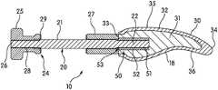
- FIG. 4is a cross-section taken along lines 4 - 4 of FIG. 3 ;
- FIG. 5is an exploded perspective view of the mobility tool of FIG. 1 ;
- FIG. 6is a top view of a head of the mobility tool of FIG. 1 ;
- FIG. 7is a cross-section taken along lines 7 - 7 of FIG. 6 ;
- FIG. 8is a cross-section view of another embodiment of a mobility tool according to aspects of the disclosure.
- FIG. 9is a side view of the mobility tool of FIG. 1 mounted on a support beam according to aspects of the disclosure.
- FIGS. 1-7illustrate an example embodiment of a mobility tool 10 according to aspects of the disclosure.
- the mobility tool 10 in FIGS. 1-7includes a head 12 configured for engaging a user's body for massage, treatment, and other purposes, which is connected to an external structure 14 that can be used to control the head 12 during use.
- the external structure 14 in FIGS. 1-7is configured as a mounting structure 20 that can be connected to a support member 16 as shown in FIG. 9 , such as a support beam of a weight rack, to mount the mobility tool 10 on the support member 16 .
- the external structure 14may be configured for different functionality, such as a handle for manual use and control of the mobility tool 10 or a mounting structure 20 for a different mounting configuration. It is understood that various different external structures 14 can be used interchangeably with the mobility tool 10 .
- the head 12 of the mobility tool 10 in FIGS. 1-7includes a body 30 with a connection structure 50 connected to the body 30 and configured to connect to the external structure 14 (e.g., the mounting structure 20 ) or a number of different external structures 14 as described above.
- the connection structure 50will be described in greater detail below, and the connection structure 50 in FIGS. 1-7 includes a bore 51 with a center axis A in the direction of elongation of the bore 51 (also referred to as a center axis of elongation).
- the body 30 in one embodimentis designed with a shape, contour, and/or rigidity in order to mimic a human hand, particularly the shape, contour, and rigidity of the human hand when engaged in a massage or therapy activity.
- the materials of the inner and outer bodies 31 , 32have different hardnesses or flexibilities, and in one embodiment, the material of the inner body 31 is a rigid material, and the material of the outer body 32 is a flexible material having greater flexibility and lower hardness than the rigid material.
- the material of the inner body 31has a hardness in the range of 60-70 Shore D (e.g., 65 Shore D), and the material of the outer body 32 has a hardness in the range of 55-65 Shore A (e.g., 60 Shore A).
- the mobility tool 10 in FIGS. 1-7may be manufactured in one embodiment by molding or otherwise forming the inner body 31 and then subsequently molding the outer body 32 onto the inner body 31 , potentially in a co-molding process.
- the body 30may have a single-material and/or single piece construction in other embodiments, such as the embodiment of FIG. 8 described below.
- the body 30generally has opposed first and second ends 33 , 34 , which may be considered proximal and distal ends, respectively, relative to the connecting structure 50 .
- the body 30generally also an outer surface 18 that includes a top surface 35 , a bottom surface 36 , and side surfaces 37 that extend between the ends 33 , 34 .
- the body 30 as shown in FIGS. 1-7has a somewhat elongated and flattened shape, such that the top and bottom surfaces 35 , 36 each have greater surface area than either of the side surfaces 37 , and in one embodiment, each of the top and bottom surfaces 35 , 36 may have greater surface area than the combined side surfaces 37 .
- the side surfaces 37 in FIGS. 1-7are generally rounded and elongated between the first and second ends 33 , 34 .
- the body 30includes a bulbous portion 38 at or proximate the first end 33 and a tongue 39 that extends from the bulbous portion 38 to the second end 34 , where the tongue 39 tapers toward the second end 34 such that the tongue has a height H (see FIG. 7 ) that decreases from the bulbous portion 38 to a minimum height H at the second end 34 .
- the height H of the body 30is measured between the top and bottom surfaces 35 and is greatest proximate the first end 33 , e.g., at the bulbous portion 38 , and smallest at the second end 34 .
- the height Hslightly decreases at a narrowed portion immediately adjacent the first end 33 .
- the top surface 35 in the embodiment of FIGS. 1-7generally is level or very slightly convex proximate the first end 33 and curves downward in a convex manner toward the second end 34 .
- the bottom surface 36has contours that may mimic the human hand in one embodiment, as described herein.
- the bottom surface 36 of the body 30 in FIGS. 1-7includes an inclined portion 40 that begins proximate the first end 33 and extends upward toward the second end 34 , and a declined portion 41 that extends downward from the inclined portion 40 to the second end 34 .
- the contours of the bottom surface 36may form smooth and/or curved transitions between the inclined and declined portions 40 , 41 themselves and between the inclined and declined portions 40 , 41 and adjacent surfaces.
- the convex portion 42forms part or all of the bottom side of the bulbous portion 38 , and the maximum height H of the body 30 is located at the convex portion 42 .
- the height H as indicated in FIG. 7is roughly the maximum height H of the body 30 when measured perpendicular to the center axis A.
- the height H in this embodimentdecreases continuously from the point of maximum height H to the second end 34 .
- the concave portion 43 in this embodimentis located on the tongue 39 , and the height H of the body 30 at the convex portion 42 is greater than the height H at the concave portion 43 .
- the maximum height H of the body 30may be at least two times, or at least three times, the minimum height H of the body 30 in one embodiment.
- the height H of the body at the apex of the convex portion 42may be at least 1.5 times the height H at the apex of the concave portion 43 in one embodiment, with the “apex” determined by reference to the center axis A as shown in FIG. 7 .
- orientations of the inclined and declined portions 40 , 41 relative to each other and to the other components of the mobility tool 10may be expressed as angles.
- the “angle” of a surface such as the inclined and declined portions 40 , 41can be expressed as best-fit lines that follow the surface of the inclined or declined portion 40 , 41 and are in the same plane as the lateral centerline of the body 30 (e.g., the center axis A of the bore 51 ).
- the “angle” of a volumetric structure such as the downward-curved portion of the tongue 39can be expressed as a line that passes through a volumetric center of the structure.
- FIG. 7illustrates examples of such lines. As shown in FIG.
- the inclined portion 40 and the declined portion 41may be oriented at an angle W of 135° to 155° (or approximately 145°) to each other, the inclined portion 40 may be oriented at an angle X of 17° to 27° (or approximately 22°) to the center axis A, and the declined portion 41 may be oriented at an angle Y of 8° to 18° (or approximately 13°) to the center axis A.
- the downward-curved portion of the tongue 39 in this embodimentmay be oriented at an angle Z of 13° to 23° (or approximately 18°) to the center axis A.
- This contour and shapegive the body 30 , and in particular the second end 34 , a shape that is advantageous for certain massage or treatment techniques and for engaging certain body tissue, including fascia.
- the second end 34 of the body 30is also contoured and shaped advantageous for certain massage or treatment techniques and for engaging certain body tissue, including fascia.
- the second end 34is rounded in the embodiment of FIGS. 1-7 , and the rounded end 34 in this embodiment has a radius of curvature of 0.20′′ to 0.40′′, or approximately 0.30′′.
- the rounded second end 34also has an arc of 145° to 170° in one embodiment.
- the junctures between the side surfaces 37 and the second end 34are also rounded when viewed from above or below, as seen in FIGS. 3 and 6 . These contours provide both functionality as described herein and comfort during use.
- the outer body 32is engaged with the surface of the inner body 31 and covers at least a portion of the surface of the inner body 31 .
- the outer surface 18 of the body 30 in one embodimentis defined by portions of the outer body 32 and the inner body 31 .
- the outer body 32may cover at least a portion of the top surface 35 , the bottom surface 36 , and the side surfaces 37 in some embodiments.
- the outer body 32may define a majority of the outer surface 18 of the body 30 and/or cover a majority of the surface of the inner body 31 in one embodiment.
- the outer body 32may define at least 75% or at least 90% of the outer surface 18 of the body 30 and/or cover at least 75% or at least 90% of the surface of the inner body 31 in another embodiment.
- the outer body 32covers the vast majority of the inner body 31 and forms the vast majority of the outer surface 18 of the body 30 .
- the inner body 31is exposed and forms part of the outer surface 18 of the body 30 only at the first end 33
- the outer body 32covers the inner body 31 and forms the entire outer surface 18 of the body on the top surface 35 , the bottom surface 36 , the side surfaces 37 , and the second end 34 .
- the outer body 32forms a portion of the first end 33 as well in FIGS. 1-7 .
- the outer body 32may completely cover the inner body 31 and form the entire outer surface 18 (with the possible exception of a bore 51 ), or the inner body 31 may cover less than 50% of the outer body 32 and/or form less than 50% of the outer surface 18 , such as covering only the portions of the tongue 39 proximate the second end 34 .
- the thickness T of the outer body 32may vary (see FIG. 7 ), and in one embodiment, the thickness T is greatest at the second end 34 .
- the thickness T of the outer body 32 at the second end 34may be at least two times, or at least three times, the thickness T at other locations on the body 30 .
- the thickness T of the outer body 32 at the second end 34is 0.68′′ to 0.78′′ (or approximately 0.73′′), and the thickness T of the outer body 32 in other locations is approximately 0.15′′ to 0.25′′ (or approximately 0.20′′). This increased thickness at the second end 34 assists in comfort and functionality.
- connection structure 50is generally configured for connection to an external component 14 , such as the mounting structure 20 in one embodiment.
- the connection structure 50 in FIGS. 1-7includes a bore 51 with a center axis A, where the bore 51 is configured to receive a portion (e.g., an end) of the mounting structure 20 .
- the bore 51is threaded in one embodiment in order to form a threaded connection with a threaded end 22 of the mounting structure 20 , as described in greater detail herein.
- the threading in the bore 51is provided by a sleeve insert 52 received in the bore 51 with internal threading to create a threaded bore 51 .
- the bore 51extends to the outer surface 18 of the body 30 to form an opening 53 for insertion of the connecting portion of the external component 14 .
- the connection structure 50 in FIGS. 1-7is positioned at the first end 33 of the body 30 and configured for engagement of the external component 14 at the first end 33 .
- the first end 33 of the body 30is relatively flattened in this embodiment, in order to facilitate engagement with the mounting structure 20 .
- the mobility tool 10may include additional connection structure 50 in one embodiment, such as a second bore 51 or other connection structure 50 configured for connection to an external component 14 in a different orientation and/or location.
- the body 30may include a second bore 51 on the bottom surface 36 , such as within the bulbous portion 38 , that is oriented at 90° or another transverse angle to the central axis A.
- the bore 51is defined exclusively within the inner body 31 and the opening 53 is formed in the first end 33 in the inner body 31 , such that the external component 14 engages only the inner body 31 .
- Any additional bores 51 or other connection structure 50 as described hereinmay be similarly configured for engagement with the inner body 31 .
- connection structure 50may be used.
- the bore 51may be smooth and/or the connection structure 50 may include a different type of retaining structure, including tabs, fasteners, adhesive, etc.
- a connection structure 50 with a smooth bore 51may be used to place the mobility tool 10 on the end of a barbell for ease of use in a gym setting where a mounting structure 20 is not provided.
- a connection structure 50 without a bore 51may be used, for example, an external structure such as a clamp, buckle, lock, post, etc. It is understood that the head 12 may be used as a mobility tool 10 without connection to any external component 14 , and that the head 12 may not have any connection structure 50 in one embodiment.
- the mounting structure 20 in FIGS. 1-7is configured for connection to a support member 16 , such as a support beam of a weight rack, to mount the mobility tool 10 on the support member 16 , as shown in FIG. 9 .
- the mounting structure 20includes a shaft 21 with an end 22 that is configured to engage the connection structure 50 , where the shaft 21 is configured to be received into and/or through a passage 23 in the support member 16 to mount the mobility tool 10 on the support member 16 .
- the end 22 in FIGS. 1-7is a threaded end 22 configured to engage the threaded bore 51 by threading, as described herein.
- the central portion of the shaft 21is smooth in FIGS. 1-7 , and is intended to be received in the passage 23 as shown in FIG. 9 .
- the mounting structure 20may also include retaining structure 24 to retain the mounting structure 20 in engagement with the support member 16 and/or to tighten the connections between these components.
- the retaining structure 24includes a retaining member 25 for connection to a second end 26 of the shaft 21 and a bushing 27 for abutting engagement with the support member 16 and/or the head 12 .
- the retaining member 24 and the bushing 27abuttingly engage opposed surfaces of the support member 16
- the bushing 27is abuttingly engaged on opposed ends by the support member 16 and the first end 33 of the body 30 .
- 1-7is in the form of a threaded cap that has a threaded bore 28 for threading onto the second end 26 of the shaft 21 (which is also threaded).
- Other retaining members 25may be used in other embodiments, and it is understood that the shaft 21 may be configured for engagement with such retaining members 25 .
- the bushing 27also receives a portion of the shaft 21 , and may be provided with structure to retain the bushing 27 in position with respect to the shaft 21 (e.g., internal threading) in one embodiment. Spacers 29 such as washers may further be used, such as for direct engagement of the surfaces of the support member 16 .
- Mounting of the mobility tool 10 as shown in FIG. 9may be accomplished by threading the head 12 onto the first end 33 of the shaft 21 of the mounting structure 20 , then inserting the second end 26 of the shaft 21 through the passage 23 in the support member 16 such that the bushing 27 is positioned between the head 12 and the support member 16 , then threading the retaining member 25 onto the second end 26 of the shaft 21 until the connection is tight and secure.
- the mobility tool 10may be mounted at different heights and orientations for desired use, and in one embodiment, may be mounted at a height and orientation so that a user can push his/her back against the second end 34 of the body 30 , using body weight and the force of gravity for assistance with accessing fascia or other deep/inaccessible tissues. Disconnection and/or disassembly of the mobility tool 10 may be accomplished in reverse order.
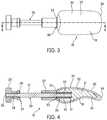
- FIG. 8illustrates another embodiment of a mobility tool 10 according to aspects of the disclosure.
- the mobility tool 10 in FIG. 8includes many components and features in common with the mobility tool 10 in FIGS. 1-7 , and these components and features are not re-described herein for the sake of brevity.
- the mobility tool 10 in FIG. 8has the same size and external shape as the mobility tool 10 in FIGS. 1-7 , as well as the same connection structure 50 .
- the mobility tool 10 in FIG. 8does not include both an inner body and an outer body as described herein with respect to FIGS. 1-7 , and instead, the mobility tool in FIG. 8 is made from a single material, which may be a single molded piece.
- the material of the mobility tool in FIG. 8may have a higher hardness than the material for outer body 32 described herein but lower hardness than the material for the inner body 31 described herein.
- Other components and features described herein, including any variations or alternate embodiments,may be incorporated into the embodiment of FIG. 8 .
- the embodiments of mobility tools 10 described hereinprovide benefits and advantages over existing mobility tools and similar devices.
- the mobility tools 10 described hereincan be quickly and easily mounted on a weight rack or other athletic equipment in a fixed position, providing the ability for a user to use the mobility tool 10 unassisted or with limited assistance.
- the mobility tools 10 described hereinhave a shape, contour, and rigidity that are particularly useful for accessing fascia and other tissues that are inaccessible for various reasons, including their depth and/or location relative to other tissue.
- the mobility tools 10 described hereinprovide for use in a variety of different configurations. Other benefits and advantages are recognizable to those skilled in the art.
- top,” “bottom,” “front,” “back,” “side,” “rear,” “proximal,” “distal,” and the like, as used herein,are intended for illustrative purposes only and do not limit the embodiments in any way unless specified with reference to a specific orientation or feature. None in this specification should be construed as requiring a specific three dimensional orientation of structures in order to fall within the scope of this invention, unless explicitly specified by the claims.
- “Integral joining technique,” as used herein,means a technique for joining two pieces so that the two pieces effectively become a single, integral piece, including, but not limited to, irreversible joining techniques such as welding, brazing, soldering, or the like, where separation of the joined pieces cannot be accomplished without structural damage thereto.
Landscapes
- Health & Medical Sciences (AREA)
- Life Sciences & Earth Sciences (AREA)
- Epidemiology (AREA)
- Pain & Pain Management (AREA)
- Physical Education & Sports Medicine (AREA)
- Rehabilitation Therapy (AREA)
- Animal Behavior & Ethology (AREA)
- General Health & Medical Sciences (AREA)
- Public Health (AREA)
- Veterinary Medicine (AREA)
- Dermatology (AREA)
- Orthopedics, Nursing, And Contraception (AREA)
- Surgical Instruments (AREA)
Abstract
Description
Claims (27)
Priority Applications (1)
| Application Number | Priority Date | Filing Date | Title |
|---|---|---|---|
| US15/917,343US10898408B2 (en) | 2017-03-09 | 2018-03-09 | Fascial mobility tool |
Applications Claiming Priority (2)
| Application Number | Priority Date | Filing Date | Title |
|---|---|---|---|
| US201762469420P | 2017-03-09 | 2017-03-09 | |
| US15/917,343US10898408B2 (en) | 2017-03-09 | 2018-03-09 | Fascial mobility tool |
Publications (2)
| Publication Number | Publication Date |
|---|---|
| US20190015288A1 US20190015288A1 (en) | 2019-01-17 |
| US10898408B2true US10898408B2 (en) | 2021-01-26 |
Family
ID=65000770
Family Applications (1)
| Application Number | Title | Priority Date | Filing Date |
|---|---|---|---|
| US15/917,343Active2038-07-28US10898408B2 (en) | 2017-03-09 | 2018-03-09 | Fascial mobility tool |
Country Status (1)
| Country | Link |
|---|---|
| US (1) | US10898408B2 (en) |
Cited By (3)
| Publication number | Priority date | Publication date | Assignee | Title |
|---|---|---|---|---|
| US20200078266A1 (en)* | 2018-09-10 | 2020-03-12 | Jeff Miller | Myofascial release apparatus |
| USD1007696S1 (en)* | 2022-11-10 | 2023-12-12 | Sichuan Qianli-beoka Medical Technology Inc. | Massage head of the fascia gun |
| USD1008473S1 (en)* | 2022-06-10 | 2023-12-19 | Sichuan Qianli-beoka Medical Technology Inc. | Massage head of the fascia gun |
Families Citing this family (4)
| Publication number | Priority date | Publication date | Assignee | Title |
|---|---|---|---|---|
| WO2020041763A1 (en)* | 2018-08-23 | 2020-02-27 | Thornburg James Gordon | Handheld massage tool and method of using the same |
| USD914988S1 (en)* | 2019-05-20 | 2021-03-30 | Jay L. LaBonte | Back scratcher |
| US11246792B2 (en)* | 2019-10-23 | 2022-02-15 | Joan Mary Held | Wall-mounted massage device |
| US20210283000A1 (en)* | 2020-03-14 | 2021-09-16 | Kusha Karvandi | Apparatus and method for relieving tightness in the hip flexor muscles |
Citations (124)
| Publication number | Priority date | Publication date | Assignee | Title |
|---|---|---|---|---|
| US1516464A (en)* | 1924-03-03 | 1924-11-18 | George C Taplin | Fulcrum block for foot treatment |
| US1723024A (en)* | 1927-02-07 | 1929-08-06 | Anna M Fisher | Exercising or molding tool for facial treatments |
| US1769872A (en)* | 1930-01-06 | 1930-07-01 | Armand Company | Massage implement |
| US1833105A (en)* | 1928-10-26 | 1931-11-24 | Louis V Aronson | Massage device |
| US2929374A (en)* | 1957-10-10 | 1960-03-22 | Frank Pasko | Combination heat transfer applicator and massager |
| US3382866A (en)* | 1965-10-20 | 1968-05-14 | Harris Jack Ramsay | Massage device with hollow applicator for holding heating or cooling media |
| US3512328A (en)* | 1967-07-07 | 1970-05-19 | Bofors Ab | Fastening device |
| US3994289A (en)* | 1975-11-17 | 1976-11-30 | The Scott & Fetzer Company | Acupressure instrument |
| USD247312S (en)* | 1976-07-19 | 1978-02-21 | Associated Mills, Inc. | Head rest for a back massaging cushion |
| US4483328A (en)* | 1982-06-18 | 1984-11-20 | Wolocko Roman A | Chiropractic instrument |
| US4520798A (en)* | 1981-11-04 | 1985-06-04 | Lewis Tommy K | Self acupressure method |
| US5016617A (en)* | 1989-12-27 | 1991-05-21 | Russell P. Wood | Automatic body massaging apparatus |
| USD326327S (en)* | 1989-06-07 | 1992-05-19 | Harold Sue | Massager |
| US5170778A (en)* | 1990-11-01 | 1992-12-15 | Ron Jamis | Body massaging device |
| USD338964S (en)* | 1991-08-07 | 1993-08-31 | Tarjoto Heru K | Massager |
| USD345801S (en)* | 1992-02-28 | 1994-04-05 | Bosch Mimi L | Massager |
| USD357323S (en)* | 1993-09-13 | 1995-04-11 | C. L. Femme Inc. | Massager |
| US5470303A (en)* | 1994-04-01 | 1995-11-28 | C. L. Femme Inc. | Massage device |
| USD373197S (en)* | 1994-06-20 | 1996-08-27 | Richard Schepper | Deep tissue massager |
| USD386879S (en)* | 1996-11-12 | 1997-11-25 | Daniels Michael P | Massage tool |
| US5810875A (en)* | 1997-05-12 | 1998-09-22 | Meilus; Algis A. | Low back and hip treatment device |
| US5817037A (en)* | 1996-01-31 | 1998-10-06 | Zurbay; Gregory J. | Soft tissue injury treatment apparatus and method |
| US5843005A (en)* | 1996-10-04 | 1998-12-01 | Chubinsky; Vladimir | Device for deep tissue massage and ionic therapy |
| US5848980A (en)* | 1997-04-25 | 1998-12-15 | Demerais; Donald A. | Hoop shaped massage apparatus |
| US5904661A (en)* | 1997-07-18 | 1999-05-18 | Bonz; Karen F. | Back scratcher with a moving arm |
| US6105182A (en)* | 1999-08-23 | 2000-08-22 | Elnar; Joseph G. | Adjustable, spa massager mounting assembly |
| US6254555B1 (en)* | 1996-08-12 | 2001-07-03 | Primary Care Delivery Corporation | Instrument for diagnosing and treating soft tissue abnormalities through augmented soft tissue mobilization |
| US20020072692A1 (en)* | 2000-12-13 | 2002-06-13 | Antonietta Batula | Crib mounted baby soothing device |
| US20020107460A1 (en)* | 2001-02-05 | 2002-08-08 | Jeanne Scheele | Intraoral myofascial release tool |
| US20020183661A1 (en)* | 2001-06-01 | 2002-12-05 | Yoo Dong-Hoon | Exercising tool for acupressure |
| US20020193714A1 (en)* | 2001-06-13 | 2002-12-19 | Pecora Ralph R. | Article and method for self-administered physical therapy to alleviate back pain |
| US20040230139A1 (en)* | 2003-05-15 | 2004-11-18 | Freddie Chang | Floating massage pad structure |
| US6830532B1 (en)* | 2003-07-30 | 2004-12-14 | Daimlerchrysler Corporation | Method for controlling a powertrain having multiple torque sources |
| US6837860B1 (en)* | 2002-09-30 | 2005-01-04 | Lynda Auletta | Cranial base massage unit |
| US6887211B1 (en)* | 1996-08-12 | 2005-05-03 | Performance Dynamics, Inc. | Instrument for diagnosing and treating soft tissue abnormalities though augmented soft tissue mobilization |
| USD518576S1 (en)* | 1996-08-12 | 2006-04-04 | Performance Dynamics, Inc. | Instrument for diagnosing and treating soft tissue abnormalities |
| US20060142675A1 (en)* | 2004-12-28 | 2006-06-29 | Sargent Eric W | Apparatus for applying pressure to a head or neck and a method for relief |
| US20070287940A1 (en)* | 2006-06-07 | 2007-12-13 | Bows, Llc | Device for caressing the body |
| US20080086066A1 (en)* | 2004-12-14 | 2008-04-10 | Munday Mary M | Neuro-muscular pressure point messager |
| US20080097262A1 (en)* | 2006-10-19 | 2008-04-24 | Darrell Adams | Massage Apparatus and Method |
| US20080139981A1 (en)* | 2006-12-08 | 2008-06-12 | Gary Walquist | Trigger point therapy device |
| US7431706B2 (en)* | 2005-06-22 | 2008-10-07 | Louis John G | Generally triangular-shaped massage tool with three different contact elements |
| USD590066S1 (en)* | 2008-07-11 | 2009-04-07 | Sportsheets International, Inc. | Contoured massager |
| US20090177210A1 (en)* | 2006-05-25 | 2009-07-09 | Roberto Francesco Durso | Skin treatment tool |
| USD596307S1 (en)* | 2008-07-11 | 2009-07-14 | Sportsheets International, Inc. | Contoured massager with bend |
| US20100004574A1 (en)* | 2008-07-07 | 2010-01-07 | Hung-Chang Chen | Kneading massage device |
| US20100036298A1 (en)* | 2008-08-08 | 2010-02-11 | Lpg Finance Industrie | Massage head and massage apparatus employing said head |
| US20100145244A1 (en)* | 2008-12-08 | 2010-06-10 | Robert Schwartz | Apparatus for application of trigger point pressure in personal fitness centers and the like before or after exercise |
| USD638549S1 (en)* | 2010-09-16 | 2011-05-24 | Scappaticci Mark J | Soft tissue massage tool |
| US20110218465A1 (en)* | 2010-03-08 | 2011-09-08 | Tsung-Hsun Yang | Massaging apparatus |
| USD645569S1 (en)* | 2008-03-07 | 2011-09-20 | Koninklijke Philips Electronics N.V. | Massager |
| US20120028765A1 (en)* | 2010-07-29 | 2012-02-02 | Christopher Robert Morin | Adjustable standing muscular releasing and stretching exercise device |
| US20120158040A1 (en)* | 2010-12-21 | 2012-06-21 | Jonathan Edward Dehors | Soft Tissue Tech Instrument |
| US20120209363A1 (en)* | 2011-02-10 | 2012-08-16 | R2T2 Solutions Llc | Hot and cold therapy device |
| US20120232446A1 (en)* | 2011-03-08 | 2012-09-13 | Ormsbee D C Dabco Roy S | Apparatus for Treating Foot Disorders |
| US20120310125A1 (en)* | 2009-11-10 | 2012-12-06 | Wendell Hall | Cylindrical roller massage tool |
| US20120323151A1 (en)* | 2007-02-16 | 2012-12-20 | Polar Fusion Llc | Rolling muscle massager |
| US20130030464A1 (en)* | 2011-03-14 | 2013-01-31 | Hiroshi Taguchi | Low back pain treatment tool |
| USD676566S1 (en)* | 2003-12-30 | 2013-02-19 | Kneads Must Limited | Massage device |
| USD677394S1 (en)* | 2012-03-09 | 2013-03-05 | Dale Montelione Grust | Massage therapy toe device |
| USD678539S1 (en)* | 2010-11-24 | 2013-03-19 | Todd M. Narson | Multifunction soft tissue mobilization instrument |
| US20130165827A1 (en)* | 2011-12-27 | 2013-06-27 | Su-Ning LIU | Body massage apparatus |
| USD686333S1 (en)* | 2012-01-31 | 2013-07-16 | Malcolm Innes | Massage tool |
| US20130197405A1 (en)* | 2011-02-10 | 2013-08-01 | R2T2 Solutions Llc | Hot and cold therapy device |
| USD687957S1 (en)* | 2012-01-27 | 2013-08-13 | Martin Heskier | Massage appliance |
| USD692570S1 (en)* | 2012-09-14 | 2013-10-29 | Derma Dream Group Ltd. | Iontophoresis device |
| US20130296750A1 (en)* | 2011-04-21 | 2013-11-07 | Mark W. Pursel | Instruments for treatment of soft tissue |
| USD696414S1 (en)* | 2013-06-12 | 2013-12-24 | Bloom Classic Co., Ltd. | Massage tool |
| US20140005581A1 (en)* | 2010-11-26 | 2014-01-02 | Mark J. Scappaticci | Fascial Abrasion Tool With Textured Surface |
| USD697629S1 (en)* | 2011-06-08 | 2014-01-14 | Hee-Soo Kim | Device for myofascial release |
| USD701613S1 (en)* | 2013-08-28 | 2014-03-25 | Christopher J. Twiggs | Massage pin |
| USD706445S1 (en)* | 2013-03-26 | 2014-06-03 | Lee Tack Stationery Manufactory Limited | Hand held massage and toning device |
| USD707842S1 (en)* | 2013-07-15 | 2014-06-24 | Hoi Ming Michael HO | Massaging backrest |
| US8801642B1 (en)* | 2011-07-11 | 2014-08-12 | Arnold Slominski | Massage tool |
| USD712056S1 (en)* | 2013-12-04 | 2014-08-26 | Align Bodyworks LLC | Massage tool |
| USD716465S1 (en)* | 2013-11-22 | 2014-10-28 | Maurice S. Kanbar Revocable Trust | Personal massager head |
| US20140336549A1 (en)* | 2013-05-13 | 2014-11-13 | Tsung-Hsun Yang | Massage Apparatus |
| US20150148592A1 (en)* | 2013-11-22 | 2015-05-28 | Maurice S. Kanbar Revocable Trust | Personal massager |
| US20150150749A1 (en)* | 2013-12-04 | 2015-06-04 | Julie Deramo | Massage tool and methods of use |
| US20150231016A1 (en)* | 2014-02-20 | 2015-08-20 | Dana Stearns | Therapeutic Compression Apparatus |
| US9132055B1 (en)* | 2010-01-08 | 2015-09-15 | Carey M Wallace | Athletic massage device |
| US20150328080A1 (en)* | 2014-05-15 | 2015-11-19 | Ian Q. Ryan | Fascial Release Ball |
| US20150351996A1 (en)* | 2012-09-25 | 2015-12-10 | Galina Bukharina | Expandable pressure point mat |
| US20160058656A1 (en)* | 2014-08-27 | 2016-03-03 | Curtis Harvel | Deep tissue massage lever roller with single-hand operation |
| USD752239S1 (en)* | 2015-04-30 | 2016-03-22 | Brant Stock | Fascial tool |
| USD752238S1 (en)* | 2015-04-20 | 2016-03-22 | Brant Stock | Fascial tool |
| USD754869S1 (en)* | 2014-06-18 | 2016-04-26 | Brant Tucker Stock | Massage tool |
| USD767780S1 (en)* | 2015-07-23 | 2016-09-27 | Tissue Tools Llc | Multi-edge instrument for treatment of soft tissue |
| US20160317387A1 (en)* | 2015-04-01 | 2016-11-03 | Bradley Cox | Combined mobility and stability apparatus |
| US20160317386A1 (en)* | 2013-05-01 | 2016-11-03 | Georgette Constance Suttman | Device for Administering Sustained Static Pressure and Force on Muscles |
| US20160324711A1 (en)* | 2009-07-09 | 2016-11-10 | Barbara J. Richmond | Craniosacral cradle system and method |
| US20160324717A1 (en)* | 2015-05-06 | 2016-11-10 | Brett W. Burton | Self-Administering Massage Device |
| US20160361223A1 (en)* | 2015-06-09 | 2016-12-15 | Geoffrey M. Muller | Massage apparatus with knuckle-shaped nodes |
| US20160367015A1 (en)* | 2013-07-03 | 2016-12-22 | Aesthetic Medical Devices | Device to optimize cosmetic injectable procedures |
| US20160367425A1 (en)* | 2015-06-20 | 2016-12-22 | Theragun, LLC | Apparatus, system, and method for a reciprocating treatment device |
| US20170135892A1 (en)* | 2015-11-12 | 2017-05-18 | Tech Tank, LLC | Trigger Point Treatment Device |
| USD788934S1 (en)* | 2015-12-04 | 2017-06-06 | Shiseido Co., Ltd. | Massage appliance |
| US20170202723A1 (en)* | 2016-01-14 | 2017-07-20 | Richard J. Serola | Contoured device for anatomical traction or correction of the spine |
| US20170216136A1 (en)* | 2014-10-17 | 2017-08-03 | Beurer Gmbh | Tissue Treatment Stick |
| US20170216133A1 (en)* | 2016-02-02 | 2017-08-03 | Chinchin Yih | Massage Roller |
| US20170231851A1 (en)* | 2014-08-06 | 2017-08-17 | Polar Fusion Llc | Massage device and system |
| US20170266794A1 (en)* | 2016-03-17 | 2017-09-21 | Ludwig Hettich Holding Gmbh & Co. Kg | Drive Element for Transmitting a Torque to a Threaded Insert Sleeve |
| US20170273850A1 (en)* | 2016-03-24 | 2017-09-28 | New Pelvic Pain Technologies Inc. | Trigger point therapy device |
| USD809151S1 (en)* | 2016-05-11 | 2018-01-30 | Lien-Tsung Li | Massage device |
| US9925110B1 (en)* | 2009-10-26 | 2018-03-27 | Tecnica Gavilan, Llc | Soft tissue massage tools |
| US20180103808A1 (en)* | 2016-10-18 | 2018-04-19 | Shenzhen Apex Technology Co., Ltd. | Back Massaging and Cleaning Device |
| US20180142832A1 (en)* | 2016-11-21 | 2018-05-24 | Warren Inouye | Multi-use mounting bracket with extension for therapeutic devices and gym accessories |
| USD825770S1 (en)* | 2017-07-31 | 2018-08-14 | Douglas J. Siemer | Back pressure point massage device |
| USD828926S1 (en)* | 2017-07-17 | 2018-09-18 | The Boiler Operation, Llc | Fascial tool |
| USD833636S1 (en)* | 2017-06-06 | 2018-11-13 | Ditu Inc. | Myofascial release tool |
| US20190008716A1 (en)* | 2017-07-05 | 2019-01-10 | Wave Tools, LLC | Physical Therapy Tools and Related Methods |
| US20190017528A1 (en)* | 2017-07-11 | 2019-01-17 | Theragun, LLC | Treatment element attachment system |
| US20190029916A1 (en)* | 2017-07-31 | 2019-01-31 | Kristie Orecchio Ennis | Fascia Therapy Tool |
| USD850642S1 (en)* | 2017-11-14 | 2019-06-04 | Kakuro Yokoyama | Massage tool |
| US10314762B1 (en)* | 2018-11-12 | 2019-06-11 | Hyper Ice, Inc. | Battery-powered percussive massage device with pressure sensor |
| USD857223S1 (en)* | 2018-06-26 | 2019-08-20 | Shiseido Co., Ltd. | Massage appliance |
| USD861182S1 (en)* | 2017-07-11 | 2019-09-24 | Theragun, LLC | Massage element |
| USD861829S1 (en)* | 2018-06-12 | 2019-10-01 | Fang Wang | Breast massager |
| USD863585S1 (en)* | 2018-06-12 | 2019-10-15 | The Pause Group, Inc. | Combined skin massage and collagen stimulating tool |
| US20190350793A1 (en)* | 2017-07-11 | 2019-11-21 | Theragun, LLC | Attachment system for a plurality of treatment members |
| US20190388295A1 (en)* | 2016-12-13 | 2019-12-26 | Sang-Man LIM | Device for strengthening spinal muscles |
| US20200078266A1 (en)* | 2018-09-10 | 2020-03-12 | Jeff Miller | Myofascial release apparatus |
| USD878615S1 (en)* | 2018-09-13 | 2020-03-17 | Darren Robert Ankosko | Instrument assisted soft tissue mobilization device |
| USD879980S1 (en)* | 2018-07-10 | 2020-03-31 | Ryan Johnston | Tool for soft tissue mobilization |
- 2018
- 2018-03-09USUS15/917,343patent/US10898408B2/enactiveActive
Patent Citations (127)
| Publication number | Priority date | Publication date | Assignee | Title |
|---|---|---|---|---|
| US1516464A (en)* | 1924-03-03 | 1924-11-18 | George C Taplin | Fulcrum block for foot treatment |
| US1723024A (en)* | 1927-02-07 | 1929-08-06 | Anna M Fisher | Exercising or molding tool for facial treatments |
| US1833105A (en)* | 1928-10-26 | 1931-11-24 | Louis V Aronson | Massage device |
| US1769872A (en)* | 1930-01-06 | 1930-07-01 | Armand Company | Massage implement |
| US2929374A (en)* | 1957-10-10 | 1960-03-22 | Frank Pasko | Combination heat transfer applicator and massager |
| US3382866A (en)* | 1965-10-20 | 1968-05-14 | Harris Jack Ramsay | Massage device with hollow applicator for holding heating or cooling media |
| US3512328A (en)* | 1967-07-07 | 1970-05-19 | Bofors Ab | Fastening device |
| US3994289A (en)* | 1975-11-17 | 1976-11-30 | The Scott & Fetzer Company | Acupressure instrument |
| USD247312S (en)* | 1976-07-19 | 1978-02-21 | Associated Mills, Inc. | Head rest for a back massaging cushion |
| US4520798A (en)* | 1981-11-04 | 1985-06-04 | Lewis Tommy K | Self acupressure method |
| US4483328A (en)* | 1982-06-18 | 1984-11-20 | Wolocko Roman A | Chiropractic instrument |
| USD326327S (en)* | 1989-06-07 | 1992-05-19 | Harold Sue | Massager |
| US5016617A (en)* | 1989-12-27 | 1991-05-21 | Russell P. Wood | Automatic body massaging apparatus |
| US5170778A (en)* | 1990-11-01 | 1992-12-15 | Ron Jamis | Body massaging device |
| USD338964S (en)* | 1991-08-07 | 1993-08-31 | Tarjoto Heru K | Massager |
| USD345801S (en)* | 1992-02-28 | 1994-04-05 | Bosch Mimi L | Massager |
| USD357323S (en)* | 1993-09-13 | 1995-04-11 | C. L. Femme Inc. | Massager |
| US5470303A (en)* | 1994-04-01 | 1995-11-28 | C. L. Femme Inc. | Massage device |
| USD373197S (en)* | 1994-06-20 | 1996-08-27 | Richard Schepper | Deep tissue massager |
| US5817037A (en)* | 1996-01-31 | 1998-10-06 | Zurbay; Gregory J. | Soft tissue injury treatment apparatus and method |
| USD518576S1 (en)* | 1996-08-12 | 2006-04-04 | Performance Dynamics, Inc. | Instrument for diagnosing and treating soft tissue abnormalities |
| US6887211B1 (en)* | 1996-08-12 | 2005-05-03 | Performance Dynamics, Inc. | Instrument for diagnosing and treating soft tissue abnormalities though augmented soft tissue mobilization |
| USD530823S1 (en)* | 1996-08-12 | 2006-10-24 | Performance Dynamics, Inc. | Instrument for diagnosing and treating soft tissue abnormalities |
| USD530429S1 (en)* | 1996-08-12 | 2006-10-17 | Performance Dynamics, Inc. | Instrument for diagnosing and treating soft tissue abnormalities |
| US6254555B1 (en)* | 1996-08-12 | 2001-07-03 | Primary Care Delivery Corporation | Instrument for diagnosing and treating soft tissue abnormalities through augmented soft tissue mobilization |
| US20010051778A1 (en)* | 1996-08-12 | 2001-12-13 | Sevier Thomas L. | Instruments for diagnosing and treating fibrotic soft tissues |
| US5843005A (en)* | 1996-10-04 | 1998-12-01 | Chubinsky; Vladimir | Device for deep tissue massage and ionic therapy |
| USD386879S (en)* | 1996-11-12 | 1997-11-25 | Daniels Michael P | Massage tool |
| US5848980A (en)* | 1997-04-25 | 1998-12-15 | Demerais; Donald A. | Hoop shaped massage apparatus |
| US5810875A (en)* | 1997-05-12 | 1998-09-22 | Meilus; Algis A. | Low back and hip treatment device |
| US5904661A (en)* | 1997-07-18 | 1999-05-18 | Bonz; Karen F. | Back scratcher with a moving arm |
| US6105182A (en)* | 1999-08-23 | 2000-08-22 | Elnar; Joseph G. | Adjustable, spa massager mounting assembly |
| US20020072692A1 (en)* | 2000-12-13 | 2002-06-13 | Antonietta Batula | Crib mounted baby soothing device |
| US20020107460A1 (en)* | 2001-02-05 | 2002-08-08 | Jeanne Scheele | Intraoral myofascial release tool |
| US20020183661A1 (en)* | 2001-06-01 | 2002-12-05 | Yoo Dong-Hoon | Exercising tool for acupressure |
| US20020193714A1 (en)* | 2001-06-13 | 2002-12-19 | Pecora Ralph R. | Article and method for self-administered physical therapy to alleviate back pain |
| US6837860B1 (en)* | 2002-09-30 | 2005-01-04 | Lynda Auletta | Cranial base massage unit |
| US20040230139A1 (en)* | 2003-05-15 | 2004-11-18 | Freddie Chang | Floating massage pad structure |
| US6830532B1 (en)* | 2003-07-30 | 2004-12-14 | Daimlerchrysler Corporation | Method for controlling a powertrain having multiple torque sources |
| USD676566S1 (en)* | 2003-12-30 | 2013-02-19 | Kneads Must Limited | Massage device |
| US20080086066A1 (en)* | 2004-12-14 | 2008-04-10 | Munday Mary M | Neuro-muscular pressure point messager |
| US20060142675A1 (en)* | 2004-12-28 | 2006-06-29 | Sargent Eric W | Apparatus for applying pressure to a head or neck and a method for relief |
| US7431706B2 (en)* | 2005-06-22 | 2008-10-07 | Louis John G | Generally triangular-shaped massage tool with three different contact elements |
| US20090177210A1 (en)* | 2006-05-25 | 2009-07-09 | Roberto Francesco Durso | Skin treatment tool |
| US20070287940A1 (en)* | 2006-06-07 | 2007-12-13 | Bows, Llc | Device for caressing the body |
| US20080097262A1 (en)* | 2006-10-19 | 2008-04-24 | Darrell Adams | Massage Apparatus and Method |
| US20080139981A1 (en)* | 2006-12-08 | 2008-06-12 | Gary Walquist | Trigger point therapy device |
| US20120323151A1 (en)* | 2007-02-16 | 2012-12-20 | Polar Fusion Llc | Rolling muscle massager |
| USD645569S1 (en)* | 2008-03-07 | 2011-09-20 | Koninklijke Philips Electronics N.V. | Massager |
| US20100004574A1 (en)* | 2008-07-07 | 2010-01-07 | Hung-Chang Chen | Kneading massage device |
| USD596307S1 (en)* | 2008-07-11 | 2009-07-14 | Sportsheets International, Inc. | Contoured massager with bend |
| USD590066S1 (en)* | 2008-07-11 | 2009-04-07 | Sportsheets International, Inc. | Contoured massager |
| US20100036298A1 (en)* | 2008-08-08 | 2010-02-11 | Lpg Finance Industrie | Massage head and massage apparatus employing said head |
| US20100145244A1 (en)* | 2008-12-08 | 2010-06-10 | Robert Schwartz | Apparatus for application of trigger point pressure in personal fitness centers and the like before or after exercise |
| US20160324711A1 (en)* | 2009-07-09 | 2016-11-10 | Barbara J. Richmond | Craniosacral cradle system and method |
| US9925110B1 (en)* | 2009-10-26 | 2018-03-27 | Tecnica Gavilan, Llc | Soft tissue massage tools |
| US20120310125A1 (en)* | 2009-11-10 | 2012-12-06 | Wendell Hall | Cylindrical roller massage tool |
| US9132055B1 (en)* | 2010-01-08 | 2015-09-15 | Carey M Wallace | Athletic massage device |
| US20110218465A1 (en)* | 2010-03-08 | 2011-09-08 | Tsung-Hsun Yang | Massaging apparatus |
| US20120028765A1 (en)* | 2010-07-29 | 2012-02-02 | Christopher Robert Morin | Adjustable standing muscular releasing and stretching exercise device |
| USD638549S1 (en)* | 2010-09-16 | 2011-05-24 | Scappaticci Mark J | Soft tissue massage tool |
| USD678539S1 (en)* | 2010-11-24 | 2013-03-19 | Todd M. Narson | Multifunction soft tissue mobilization instrument |
| US20140005581A1 (en)* | 2010-11-26 | 2014-01-02 | Mark J. Scappaticci | Fascial Abrasion Tool With Textured Surface |
| US20120158040A1 (en)* | 2010-12-21 | 2012-06-21 | Jonathan Edward Dehors | Soft Tissue Tech Instrument |
| US20130197405A1 (en)* | 2011-02-10 | 2013-08-01 | R2T2 Solutions Llc | Hot and cold therapy device |
| US20120209363A1 (en)* | 2011-02-10 | 2012-08-16 | R2T2 Solutions Llc | Hot and cold therapy device |
| US20120232446A1 (en)* | 2011-03-08 | 2012-09-13 | Ormsbee D C Dabco Roy S | Apparatus for Treating Foot Disorders |
| US20130030464A1 (en)* | 2011-03-14 | 2013-01-31 | Hiroshi Taguchi | Low back pain treatment tool |
| US20130296750A1 (en)* | 2011-04-21 | 2013-11-07 | Mark W. Pursel | Instruments for treatment of soft tissue |
| USD697629S1 (en)* | 2011-06-08 | 2014-01-14 | Hee-Soo Kim | Device for myofascial release |
| US8801642B1 (en)* | 2011-07-11 | 2014-08-12 | Arnold Slominski | Massage tool |
| US20130165827A1 (en)* | 2011-12-27 | 2013-06-27 | Su-Ning LIU | Body massage apparatus |
| USD687957S1 (en)* | 2012-01-27 | 2013-08-13 | Martin Heskier | Massage appliance |
| USD686333S1 (en)* | 2012-01-31 | 2013-07-16 | Malcolm Innes | Massage tool |
| USD677394S1 (en)* | 2012-03-09 | 2013-03-05 | Dale Montelione Grust | Massage therapy toe device |
| USD692570S1 (en)* | 2012-09-14 | 2013-10-29 | Derma Dream Group Ltd. | Iontophoresis device |
| US20150351996A1 (en)* | 2012-09-25 | 2015-12-10 | Galina Bukharina | Expandable pressure point mat |
| USD706445S1 (en)* | 2013-03-26 | 2014-06-03 | Lee Tack Stationery Manufactory Limited | Hand held massage and toning device |
| US20160317386A1 (en)* | 2013-05-01 | 2016-11-03 | Georgette Constance Suttman | Device for Administering Sustained Static Pressure and Force on Muscles |
| US20140336549A1 (en)* | 2013-05-13 | 2014-11-13 | Tsung-Hsun Yang | Massage Apparatus |
| USD696414S1 (en)* | 2013-06-12 | 2013-12-24 | Bloom Classic Co., Ltd. | Massage tool |
| US20160367015A1 (en)* | 2013-07-03 | 2016-12-22 | Aesthetic Medical Devices | Device to optimize cosmetic injectable procedures |
| USD707842S1 (en)* | 2013-07-15 | 2014-06-24 | Hoi Ming Michael HO | Massaging backrest |
| USD701613S1 (en)* | 2013-08-28 | 2014-03-25 | Christopher J. Twiggs | Massage pin |
| USD716465S1 (en)* | 2013-11-22 | 2014-10-28 | Maurice S. Kanbar Revocable Trust | Personal massager head |
| US20150148592A1 (en)* | 2013-11-22 | 2015-05-28 | Maurice S. Kanbar Revocable Trust | Personal massager |
| US20150150749A1 (en)* | 2013-12-04 | 2015-06-04 | Julie Deramo | Massage tool and methods of use |
| USD712056S1 (en)* | 2013-12-04 | 2014-08-26 | Align Bodyworks LLC | Massage tool |
| US20150231016A1 (en)* | 2014-02-20 | 2015-08-20 | Dana Stearns | Therapeutic Compression Apparatus |
| US20150328080A1 (en)* | 2014-05-15 | 2015-11-19 | Ian Q. Ryan | Fascial Release Ball |
| USD754869S1 (en)* | 2014-06-18 | 2016-04-26 | Brant Tucker Stock | Massage tool |
| US20170231851A1 (en)* | 2014-08-06 | 2017-08-17 | Polar Fusion Llc | Massage device and system |
| US20160058656A1 (en)* | 2014-08-27 | 2016-03-03 | Curtis Harvel | Deep tissue massage lever roller with single-hand operation |
| US20170216136A1 (en)* | 2014-10-17 | 2017-08-03 | Beurer Gmbh | Tissue Treatment Stick |
| US20160317387A1 (en)* | 2015-04-01 | 2016-11-03 | Bradley Cox | Combined mobility and stability apparatus |
| USD752238S1 (en)* | 2015-04-20 | 2016-03-22 | Brant Stock | Fascial tool |
| USD752239S1 (en)* | 2015-04-30 | 2016-03-22 | Brant Stock | Fascial tool |
| US20160324717A1 (en)* | 2015-05-06 | 2016-11-10 | Brett W. Burton | Self-Administering Massage Device |
| US20160361223A1 (en)* | 2015-06-09 | 2016-12-15 | Geoffrey M. Muller | Massage apparatus with knuckle-shaped nodes |
| US20160367425A1 (en)* | 2015-06-20 | 2016-12-22 | Theragun, LLC | Apparatus, system, and method for a reciprocating treatment device |
| USD767780S1 (en)* | 2015-07-23 | 2016-09-27 | Tissue Tools Llc | Multi-edge instrument for treatment of soft tissue |
| US20170135892A1 (en)* | 2015-11-12 | 2017-05-18 | Tech Tank, LLC | Trigger Point Treatment Device |
| USD788934S1 (en)* | 2015-12-04 | 2017-06-06 | Shiseido Co., Ltd. | Massage appliance |
| US20170202723A1 (en)* | 2016-01-14 | 2017-07-20 | Richard J. Serola | Contoured device for anatomical traction or correction of the spine |
| US20170216133A1 (en)* | 2016-02-02 | 2017-08-03 | Chinchin Yih | Massage Roller |
| US20170266794A1 (en)* | 2016-03-17 | 2017-09-21 | Ludwig Hettich Holding Gmbh & Co. Kg | Drive Element for Transmitting a Torque to a Threaded Insert Sleeve |
| US20170273850A1 (en)* | 2016-03-24 | 2017-09-28 | New Pelvic Pain Technologies Inc. | Trigger point therapy device |
| USD809151S1 (en)* | 2016-05-11 | 2018-01-30 | Lien-Tsung Li | Massage device |
| US20180103808A1 (en)* | 2016-10-18 | 2018-04-19 | Shenzhen Apex Technology Co., Ltd. | Back Massaging and Cleaning Device |
| US20180142832A1 (en)* | 2016-11-21 | 2018-05-24 | Warren Inouye | Multi-use mounting bracket with extension for therapeutic devices and gym accessories |
| US20190388295A1 (en)* | 2016-12-13 | 2019-12-26 | Sang-Man LIM | Device for strengthening spinal muscles |
| USD833636S1 (en)* | 2017-06-06 | 2018-11-13 | Ditu Inc. | Myofascial release tool |
| US20190008716A1 (en)* | 2017-07-05 | 2019-01-10 | Wave Tools, LLC | Physical Therapy Tools and Related Methods |
| US20190017528A1 (en)* | 2017-07-11 | 2019-01-17 | Theragun, LLC | Treatment element attachment system |
| US20190350793A1 (en)* | 2017-07-11 | 2019-11-21 | Theragun, LLC | Attachment system for a plurality of treatment members |
| USD861182S1 (en)* | 2017-07-11 | 2019-09-24 | Theragun, LLC | Massage element |
| USD828926S1 (en)* | 2017-07-17 | 2018-09-18 | The Boiler Operation, Llc | Fascial tool |
| US20190029916A1 (en)* | 2017-07-31 | 2019-01-31 | Kristie Orecchio Ennis | Fascia Therapy Tool |
| USD825770S1 (en)* | 2017-07-31 | 2018-08-14 | Douglas J. Siemer | Back pressure point massage device |
| USD850642S1 (en)* | 2017-11-14 | 2019-06-04 | Kakuro Yokoyama | Massage tool |
| USD863585S1 (en)* | 2018-06-12 | 2019-10-15 | The Pause Group, Inc. | Combined skin massage and collagen stimulating tool |
| USD861829S1 (en)* | 2018-06-12 | 2019-10-01 | Fang Wang | Breast massager |
| USD857223S1 (en)* | 2018-06-26 | 2019-08-20 | Shiseido Co., Ltd. | Massage appliance |
| USD879980S1 (en)* | 2018-07-10 | 2020-03-31 | Ryan Johnston | Tool for soft tissue mobilization |
| US20200078266A1 (en)* | 2018-09-10 | 2020-03-12 | Jeff Miller | Myofascial release apparatus |
| USD878615S1 (en)* | 2018-09-13 | 2020-03-17 | Darren Robert Ankosko | Instrument assisted soft tissue mobilization device |
| US10314762B1 (en)* | 2018-11-12 | 2019-06-11 | Hyper Ice, Inc. | Battery-powered percussive massage device with pressure sensor |
Non-Patent Citations (3)
| Title |
|---|
| Hudacek, Laura, "How to Optimize Adhesion in Hard-Soft Overmolding" Feb. 1, 2004 https://www.ptonline.com/articles/articles/how-to-optimize-adhesion-in-hard-soft-overmolding (Year: 2004).* |
| Omnexus "Comprehensive Guide on Polyvinyl Chloride (PVC)" https://onnnexus.specialchem.com/selection-guide/polyvinyl-chloride-pvc-plastic#RigidvsFlexible (Year: 2018).* |
| Star Thermoplastics "Using Hardness Scales with TPEs" https://www.starthermoplastics.com/our-chemistry/shore-hardness-scale/ (Year: 2014).* |
Cited By (6)
| Publication number | Priority date | Publication date | Assignee | Title |
|---|---|---|---|---|
| US20200078266A1 (en)* | 2018-09-10 | 2020-03-12 | Jeff Miller | Myofascial release apparatus |
| US11986438B2 (en)* | 2018-09-10 | 2024-05-21 | Jeff Miller | Myofascial release apparatus |
| US20240261187A1 (en)* | 2018-09-10 | 2024-08-08 | Jeff Miller | Myofascial release apparatus |
| US12233023B2 (en)* | 2018-09-10 | 2025-02-25 | Jeff Miller | Myofascial release apparatus |
| USD1008473S1 (en)* | 2022-06-10 | 2023-12-19 | Sichuan Qianli-beoka Medical Technology Inc. | Massage head of the fascia gun |
| USD1007696S1 (en)* | 2022-11-10 | 2023-12-12 | Sichuan Qianli-beoka Medical Technology Inc. | Massage head of the fascia gun |
Also Published As
| Publication number | Publication date |
|---|---|
| US20190015288A1 (en) | 2019-01-17 |
Similar Documents
| Publication | Publication Date | Title |
|---|---|---|
| US10898408B2 (en) | Fascial mobility tool | |
| US12233023B2 (en) | Myofascial release apparatus | |
| US9023078B2 (en) | Soft tissue tech instrument | |
| US8821425B2 (en) | Device and method for applying pressure to mammalian limb | |
| US20180126218A1 (en) | Finger training method and device thereof | |
| USD898844S1 (en) | Cross-member for a climbing hold exercise rig | |
| US20170296889A1 (en) | Hosel Assembly | |
| US8267844B2 (en) | Gripping device | |
| US20090012435A1 (en) | Adjustable massage tool | |
| JP3244201U (en) | New fins and fin blades | |
| US10814162B2 (en) | Exercise equipment for strengthening pelvis | |
| US7090588B2 (en) | Golf swing training device | |
| US20190070067A1 (en) | Stress Ball Massaging Device | |
| TR201809152T4 (en) | A handle for a cognitive training device and a cognitive training device containing this handle. | |
| US20050049068A1 (en) | Supplementary structure of swinging a golf club | |
| US7951053B1 (en) | Exercising assist method and apparatus | |
| JP6559909B2 (en) | Apparatus and method for golf practice | |
| JP6746654B2 (en) | Golf practice equipment | |
| US20070105638A1 (en) | Prosthetic device for golfing | |
| US11638847B2 (en) | Stretch exercise tool | |
| USD1013078S1 (en) | Head for a golf club | |
| US11358044B2 (en) | Upper body rotational assistive device | |
| JP3149428U (en) | Walking aid | |
| CA2528018C (en) | Gripping device | |
| KR200285540Y1 (en) | Grip corrective golf club |
Legal Events
| Date | Code | Title | Description |
|---|---|---|---|
| FEPP | Fee payment procedure | Free format text:ENTITY STATUS SET TO UNDISCOUNTED (ORIGINAL EVENT CODE: BIG.); ENTITY STATUS OF PATENT OWNER: LARGE ENTITY | |
| AS | Assignment | Owner name:COULTER VENTURES, LLC, OHIO Free format text:ASSIGNMENT OF ASSIGNORS INTEREST;ASSIGNOR:AVUS DESIGN LP;REEL/FRAME:047907/0049 Effective date:20180925 Owner name:COULTER VENTURES, LLC, OHIO Free format text:ASSIGNMENT OF ASSIGNORS INTEREST;ASSIGNOR:MERRILL, CHARLES SCOTT;REEL/FRAME:047906/0392 Effective date:20180706 Owner name:AVUS DESIGN LP, CALIFORNIA Free format text:ASSIGNMENT OF ASSIGNORS INTEREST;ASSIGNOR:JONES, DYLAN;REEL/FRAME:047906/0693 Effective date:20180925 | |
| STPP | Information on status: patent application and granting procedure in general | Free format text:DOCKETED NEW CASE - READY FOR EXAMINATION | |
| STPP | Information on status: patent application and granting procedure in general | Free format text:NON FINAL ACTION MAILED | |
| STPP | Information on status: patent application and granting procedure in general | Free format text:RESPONSE TO NON-FINAL OFFICE ACTION ENTERED AND FORWARDED TO EXAMINER | |
| STPP | Information on status: patent application and granting procedure in general | Free format text:NOTICE OF ALLOWANCE MAILED -- APPLICATION RECEIVED IN OFFICE OF PUBLICATIONS | |
| STPP | Information on status: patent application and granting procedure in general | Free format text:AWAITING TC RESP, ISSUE FEE PAYMENT VERIFIED | |
| STCF | Information on status: patent grant | Free format text:PATENTED CASE | |
| MAFP | Maintenance fee payment | Free format text:PAYMENT OF MAINTENANCE FEE, 4TH YEAR, LARGE ENTITY (ORIGINAL EVENT CODE: M1551); ENTITY STATUS OF PATENT OWNER: LARGE ENTITY Year of fee payment:4 |