US10898336B2 - Femoral and humeral stem geometry and implantation method for orthopedic joint reconstruction - Google Patents
Femoral and humeral stem geometry and implantation method for orthopedic joint reconstructionDownload PDFInfo
- Publication number
- US10898336B2 US10898336B2US15/250,606US201615250606AUS10898336B2US 10898336 B2US10898336 B2US 10898336B2US 201615250606 AUS201615250606 AUS 201615250606AUS 10898336 B2US10898336 B2US 10898336B2
- Authority
- US
- United States
- Prior art keywords
- stem
- body portion
- proximal
- medial
- proximal body
- Prior art date
- Legal status (The legal status is an assumption and is not a legal conclusion. Google has not performed a legal analysis and makes no representation as to the accuracy of the status listed.)
- Active
Links
- 230000000399orthopedic effectEffects0.000titleclaimsabstractdescription13
- 238000000034methodMethods0.000titleabstractdescription29
- 238000002513implantationMethods0.000titledescription7
- 210000000988bone and boneAnatomy0.000claimsabstractdescription79
- 238000002271resectionMethods0.000claimsabstractdescription41
- 210000002758humerusAnatomy0.000claimsdescription50
- 210000000689upper legAnatomy0.000claimsdescription11
- 238000001356surgical procedureMethods0.000claimsdescription5
- 238000002278reconstructive surgeryMethods0.000claims1
- 239000007943implantSubstances0.000abstractdescription99
- 230000003278mimic effectEffects0.000abstractdescription7
- 210000003739neckAnatomy0.000description18
- 210000000323shoulder jointAnatomy0.000description16
- 241001653121GlenoidesSpecies0.000description9
- 241001465754MetazoaSpecies0.000description8
- 230000008901benefitEffects0.000description6
- 230000008878couplingEffects0.000description6
- 238000010168coupling processMethods0.000description6
- 238000005859coupling reactionMethods0.000description6
- 239000000463materialSubstances0.000description6
- 210000003205muscleAnatomy0.000description6
- 238000002360preparation methodMethods0.000description6
- 210000001624hipAnatomy0.000description5
- 210000000281joint capsuleAnatomy0.000description5
- 210000003041ligamentAnatomy0.000description5
- 230000008569processEffects0.000description5
- 210000000513rotator cuffAnatomy0.000description5
- 210000001258synovial membraneAnatomy0.000description5
- 230000037237body shapeEffects0.000description4
- 210000004394hip jointAnatomy0.000description4
- 238000003780insertionMethods0.000description4
- 230000037431insertionEffects0.000description4
- 238000012986modificationMethods0.000description4
- 230000004048modificationEffects0.000description4
- 210000001991scapulaAnatomy0.000description4
- 210000002435tendonAnatomy0.000description4
- 206010023204Joint dislocationDiseases0.000description3
- 210000002659acromionAnatomy0.000description3
- 210000000845cartilageAnatomy0.000description3
- 230000001054cortical effectEffects0.000description3
- 230000006378damageEffects0.000description3
- 230000006870functionEffects0.000description3
- 230000000750progressive effectEffects0.000description3
- 210000001519tissueAnatomy0.000description3
- 230000007704transitionEffects0.000description3
- 208000024288Rotator Cuff injuryDiseases0.000description2
- 208000027418Wounds and injuryDiseases0.000description2
- 210000000588acetabulumAnatomy0.000description2
- 210000000784arm boneAnatomy0.000description2
- 239000002775capsuleSubstances0.000description2
- 208000037976chronic inflammationDiseases0.000description2
- 230000006020chronic inflammationEffects0.000description2
- 210000003109clavicleAnatomy0.000description2
- 208000014674injuryDiseases0.000description2
- 230000001788irregularEffects0.000description2
- 210000001503jointAnatomy0.000description2
- 201000008482osteoarthritisDiseases0.000description2
- 206010039073rheumatoid arthritisDiseases0.000description2
- 238000004513sizingMethods0.000description2
- 210000004872soft tissueAnatomy0.000description2
- 210000001562sternumAnatomy0.000description2
- 210000001694thigh boneAnatomy0.000description2
- 241001260012BursaSpecies0.000description1
- 206010006811BursitisDiseases0.000description1
- 208000008877Shoulder DislocationDiseases0.000description1
- 208000000491TendinopathyDiseases0.000description1
- 206010043255TendonitisDiseases0.000description1
- 210000000142acromioclavicular jointAnatomy0.000description1
- 210000003484anatomyAnatomy0.000description1
- 210000000436anusAnatomy0.000description1
- 210000001188articular cartilageAnatomy0.000description1
- 230000002146bilateral effectEffects0.000description1
- 230000037180bone healthEffects0.000description1
- 230000008859changeEffects0.000description1
- 230000007850degenerationEffects0.000description1
- 230000003412degenerative effectEffects0.000description1
- 230000001627detrimental effectEffects0.000description1
- 238000011161developmentMethods0.000description1
- 238000005553drillingMethods0.000description1
- 238000002474experimental methodMethods0.000description1
- 210000003414extremityAnatomy0.000description1
- 239000000835fiberSubstances0.000description1
- 210000000968fibrocartilageAnatomy0.000description1
- 238000007429general methodMethods0.000description1
- 230000005484gravityEffects0.000description1
- 210000004095humeral headAnatomy0.000description1
- 230000003447ipsilateral effectEffects0.000description1
- 230000008407joint functionEffects0.000description1
- 210000002414legAnatomy0.000description1
- 238000005259measurementMethods0.000description1
- 230000007246mechanismEffects0.000description1
- 239000012528membraneSubstances0.000description1
- 239000002184metalSubstances0.000description1
- 239000000203mixtureSubstances0.000description1
- 210000003049pelvic boneAnatomy0.000description1
- 210000004197pelvisAnatomy0.000description1
- 230000002093peripheral effectEffects0.000description1
- 230000003252repetitive effectEffects0.000description1
- 230000004044responseEffects0.000description1
- 238000007493shaping processMethods0.000description1
- 239000007858starting materialSubstances0.000description1
- 210000001898sternoclavicular jointAnatomy0.000description1
- 238000005728strengtheningMethods0.000description1
- 239000000126substanceSubstances0.000description1
- 230000009182swimmingEffects0.000description1
- 201000004415tendinitisDiseases0.000description1
- 238000012360testing methodMethods0.000description1
- 230000000007visual effectEffects0.000description1
Images


Classifications
- A—HUMAN NECESSITIES
- A61—MEDICAL OR VETERINARY SCIENCE; HYGIENE
- A61F—FILTERS IMPLANTABLE INTO BLOOD VESSELS; PROSTHESES; DEVICES PROVIDING PATENCY TO, OR PREVENTING COLLAPSING OF, TUBULAR STRUCTURES OF THE BODY, e.g. STENTS; ORTHOPAEDIC, NURSING OR CONTRACEPTIVE DEVICES; FOMENTATION; TREATMENT OR PROTECTION OF EYES OR EARS; BANDAGES, DRESSINGS OR ABSORBENT PADS; FIRST-AID KITS
- A61F2/00—Filters implantable into blood vessels; Prostheses, i.e. artificial substitutes or replacements for parts of the body; Appliances for connecting them with the body; Devices providing patency to, or preventing collapsing of, tubular structures of the body, e.g. stents
- A61F2/02—Prostheses implantable into the body
- A61F2/30—Joints
- A61F2/32—Joints for the hip
- A61F2/36—Femoral heads ; Femoral endoprostheses
- A61F2/3662—Femoral shafts
- A—HUMAN NECESSITIES
- A61—MEDICAL OR VETERINARY SCIENCE; HYGIENE
- A61B—DIAGNOSIS; SURGERY; IDENTIFICATION
- A61B17/00—Surgical instruments, devices or methods
- A61B17/16—Instruments for performing osteoclasis; Drills or chisels for bones; Trepans
- A61B17/164—Instruments for performing osteoclasis; Drills or chisels for bones; Trepans intramedullary
- A—HUMAN NECESSITIES
- A61—MEDICAL OR VETERINARY SCIENCE; HYGIENE
- A61B—DIAGNOSIS; SURGERY; IDENTIFICATION
- A61B17/00—Surgical instruments, devices or methods
- A61B17/16—Instruments for performing osteoclasis; Drills or chisels for bones; Trepans
- A61B17/1659—Surgical rasps, files, planes, or scrapers
- A—HUMAN NECESSITIES
- A61—MEDICAL OR VETERINARY SCIENCE; HYGIENE
- A61B—DIAGNOSIS; SURGERY; IDENTIFICATION
- A61B17/00—Surgical instruments, devices or methods
- A61B17/16—Instruments for performing osteoclasis; Drills or chisels for bones; Trepans
- A61B17/1662—Instruments for performing osteoclasis; Drills or chisels for bones; Trepans for particular parts of the body
- A61B17/1664—Instruments for performing osteoclasis; Drills or chisels for bones; Trepans for particular parts of the body for the hip
- A61B17/1668—Instruments for performing osteoclasis; Drills or chisels for bones; Trepans for particular parts of the body for the hip for the upper femur
- A—HUMAN NECESSITIES
- A61—MEDICAL OR VETERINARY SCIENCE; HYGIENE
- A61B—DIAGNOSIS; SURGERY; IDENTIFICATION
- A61B17/00—Surgical instruments, devices or methods
- A61B17/16—Instruments for performing osteoclasis; Drills or chisels for bones; Trepans
- A61B17/1662—Instruments for performing osteoclasis; Drills or chisels for bones; Trepans for particular parts of the body
- A61B17/1684—Instruments for performing osteoclasis; Drills or chisels for bones; Trepans for particular parts of the body for the shoulder
- A—HUMAN NECESSITIES
- A61—MEDICAL OR VETERINARY SCIENCE; HYGIENE
- A61F—FILTERS IMPLANTABLE INTO BLOOD VESSELS; PROSTHESES; DEVICES PROVIDING PATENCY TO, OR PREVENTING COLLAPSING OF, TUBULAR STRUCTURES OF THE BODY, e.g. STENTS; ORTHOPAEDIC, NURSING OR CONTRACEPTIVE DEVICES; FOMENTATION; TREATMENT OR PROTECTION OF EYES OR EARS; BANDAGES, DRESSINGS OR ABSORBENT PADS; FIRST-AID KITS
- A61F2/00—Filters implantable into blood vessels; Prostheses, i.e. artificial substitutes or replacements for parts of the body; Appliances for connecting them with the body; Devices providing patency to, or preventing collapsing of, tubular structures of the body, e.g. stents
- A61F2/02—Prostheses implantable into the body
- A61F2/30—Joints
- A61F2/40—Joints for shoulders
- A61F2/4059—Humeral shafts
- A—HUMAN NECESSITIES
- A61—MEDICAL OR VETERINARY SCIENCE; HYGIENE
- A61B—DIAGNOSIS; SURGERY; IDENTIFICATION
- A61B17/00—Surgical instruments, devices or methods
- A61B2017/0046—Surgical instruments, devices or methods with a releasable handle; with handle and operating part separable
- A—HUMAN NECESSITIES
- A61—MEDICAL OR VETERINARY SCIENCE; HYGIENE
- A61B—DIAGNOSIS; SURGERY; IDENTIFICATION
- A61B17/00—Surgical instruments, devices or methods
- A61B2017/0046—Surgical instruments, devices or methods with a releasable handle; with handle and operating part separable
- A61B2017/00464—Surgical instruments, devices or methods with a releasable handle; with handle and operating part separable for use with different instruments
- A—HUMAN NECESSITIES
- A61—MEDICAL OR VETERINARY SCIENCE; HYGIENE
- A61B—DIAGNOSIS; SURGERY; IDENTIFICATION
- A61B90/00—Instruments, implements or accessories specially adapted for surgery or diagnosis and not covered by any of the groups A61B1/00 - A61B50/00, e.g. for luxation treatment or for protecting wound edges
- A61B90/06—Measuring instruments not otherwise provided for
- A61B2090/062—Measuring instruments not otherwise provided for penetration depth
- A—HUMAN NECESSITIES
- A61—MEDICAL OR VETERINARY SCIENCE; HYGIENE
- A61F—FILTERS IMPLANTABLE INTO BLOOD VESSELS; PROSTHESES; DEVICES PROVIDING PATENCY TO, OR PREVENTING COLLAPSING OF, TUBULAR STRUCTURES OF THE BODY, e.g. STENTS; ORTHOPAEDIC, NURSING OR CONTRACEPTIVE DEVICES; FOMENTATION; TREATMENT OR PROTECTION OF EYES OR EARS; BANDAGES, DRESSINGS OR ABSORBENT PADS; FIRST-AID KITS
- A61F2/00—Filters implantable into blood vessels; Prostheses, i.e. artificial substitutes or replacements for parts of the body; Appliances for connecting them with the body; Devices providing patency to, or preventing collapsing of, tubular structures of the body, e.g. stents
- A61F2/02—Prostheses implantable into the body
- A61F2/30—Joints
- A61F2/32—Joints for the hip
- A61F2/36—Femoral heads ; Femoral endoprostheses
- A—HUMAN NECESSITIES
- A61—MEDICAL OR VETERINARY SCIENCE; HYGIENE
- A61F—FILTERS IMPLANTABLE INTO BLOOD VESSELS; PROSTHESES; DEVICES PROVIDING PATENCY TO, OR PREVENTING COLLAPSING OF, TUBULAR STRUCTURES OF THE BODY, e.g. STENTS; ORTHOPAEDIC, NURSING OR CONTRACEPTIVE DEVICES; FOMENTATION; TREATMENT OR PROTECTION OF EYES OR EARS; BANDAGES, DRESSINGS OR ABSORBENT PADS; FIRST-AID KITS
- A61F2/00—Filters implantable into blood vessels; Prostheses, i.e. artificial substitutes or replacements for parts of the body; Appliances for connecting them with the body; Devices providing patency to, or preventing collapsing of, tubular structures of the body, e.g. stents
- A61F2/02—Prostheses implantable into the body
- A61F2/30—Joints
- A61F2002/30001—Additional features of subject-matter classified in A61F2/28, A61F2/30 and subgroups thereof
- A61F2002/30316—The prosthesis having different structural features at different locations within the same prosthesis; Connections between prosthetic parts; Special structural features of bone or joint prostheses not otherwise provided for
- A61F2002/30329—Connections or couplings between prosthetic parts, e.g. between modular parts; Connecting elements
- A61F2002/30331—Connections or couplings between prosthetic parts, e.g. between modular parts; Connecting elements made by longitudinally pushing a protrusion into a complementarily-shaped recess, e.g. held by friction fit
- A61F2002/30332—Conically- or frustoconically-shaped protrusion and recess
- A—HUMAN NECESSITIES
- A61—MEDICAL OR VETERINARY SCIENCE; HYGIENE
- A61F—FILTERS IMPLANTABLE INTO BLOOD VESSELS; PROSTHESES; DEVICES PROVIDING PATENCY TO, OR PREVENTING COLLAPSING OF, TUBULAR STRUCTURES OF THE BODY, e.g. STENTS; ORTHOPAEDIC, NURSING OR CONTRACEPTIVE DEVICES; FOMENTATION; TREATMENT OR PROTECTION OF EYES OR EARS; BANDAGES, DRESSINGS OR ABSORBENT PADS; FIRST-AID KITS
- A61F2/00—Filters implantable into blood vessels; Prostheses, i.e. artificial substitutes or replacements for parts of the body; Appliances for connecting them with the body; Devices providing patency to, or preventing collapsing of, tubular structures of the body, e.g. stents
- A61F2/02—Prostheses implantable into the body
- A61F2/30—Joints
- A61F2002/30001—Additional features of subject-matter classified in A61F2/28, A61F2/30 and subgroups thereof
- A61F2002/30316—The prosthesis having different structural features at different locations within the same prosthesis; Connections between prosthetic parts; Special structural features of bone or joint prostheses not otherwise provided for
- A61F2002/30535—Special structural features of bone or joint prostheses not otherwise provided for
- A61F2002/30537—Special structural features of bone or joint prostheses not otherwise provided for adjustable
- A61F2002/30538—Special structural features of bone or joint prostheses not otherwise provided for adjustable for adjusting angular orientation
- A61F2002/3054—Special structural features of bone or joint prostheses not otherwise provided for adjustable for adjusting angular orientation about a connection axis or implantation axis for selecting any one of a plurality of radial orientations between two modular parts, e.g. Morse taper connections, at discrete positions, angular positions or continuous positions
- A—HUMAN NECESSITIES
- A61—MEDICAL OR VETERINARY SCIENCE; HYGIENE
- A61F—FILTERS IMPLANTABLE INTO BLOOD VESSELS; PROSTHESES; DEVICES PROVIDING PATENCY TO, OR PREVENTING COLLAPSING OF, TUBULAR STRUCTURES OF THE BODY, e.g. STENTS; ORTHOPAEDIC, NURSING OR CONTRACEPTIVE DEVICES; FOMENTATION; TREATMENT OR PROTECTION OF EYES OR EARS; BANDAGES, DRESSINGS OR ABSORBENT PADS; FIRST-AID KITS
- A61F2/00—Filters implantable into blood vessels; Prostheses, i.e. artificial substitutes or replacements for parts of the body; Appliances for connecting them with the body; Devices providing patency to, or preventing collapsing of, tubular structures of the body, e.g. stents
- A61F2/02—Prostheses implantable into the body
- A61F2/30—Joints
- A61F2002/30001—Additional features of subject-matter classified in A61F2/28, A61F2/30 and subgroups thereof
- A61F2002/30316—The prosthesis having different structural features at different locations within the same prosthesis; Connections between prosthetic parts; Special structural features of bone or joint prostheses not otherwise provided for
- A61F2002/30535—Special structural features of bone or joint prostheses not otherwise provided for
- A61F2002/30604—Special structural features of bone or joint prostheses not otherwise provided for modular
- A61F2002/30607—Kits of prosthetic parts to be assembled in various combinations for forming different prostheses
- A—HUMAN NECESSITIES
- A61—MEDICAL OR VETERINARY SCIENCE; HYGIENE
- A61F—FILTERS IMPLANTABLE INTO BLOOD VESSELS; PROSTHESES; DEVICES PROVIDING PATENCY TO, OR PREVENTING COLLAPSING OF, TUBULAR STRUCTURES OF THE BODY, e.g. STENTS; ORTHOPAEDIC, NURSING OR CONTRACEPTIVE DEVICES; FOMENTATION; TREATMENT OR PROTECTION OF EYES OR EARS; BANDAGES, DRESSINGS OR ABSORBENT PADS; FIRST-AID KITS
- A61F2/00—Filters implantable into blood vessels; Prostheses, i.e. artificial substitutes or replacements for parts of the body; Appliances for connecting them with the body; Devices providing patency to, or preventing collapsing of, tubular structures of the body, e.g. stents
- A61F2/02—Prostheses implantable into the body
- A61F2/30—Joints
- A61F2002/30001—Additional features of subject-matter classified in A61F2/28, A61F2/30 and subgroups thereof
- A61F2002/30316—The prosthesis having different structural features at different locations within the same prosthesis; Connections between prosthetic parts; Special structural features of bone or joint prostheses not otherwise provided for
- A61F2002/30535—Special structural features of bone or joint prostheses not otherwise provided for
- A61F2002/30604—Special structural features of bone or joint prostheses not otherwise provided for modular
- A61F2002/30616—Sets comprising a plurality of prosthetic parts of different sizes or orientations
- A—HUMAN NECESSITIES
- A61—MEDICAL OR VETERINARY SCIENCE; HYGIENE
- A61F—FILTERS IMPLANTABLE INTO BLOOD VESSELS; PROSTHESES; DEVICES PROVIDING PATENCY TO, OR PREVENTING COLLAPSING OF, TUBULAR STRUCTURES OF THE BODY, e.g. STENTS; ORTHOPAEDIC, NURSING OR CONTRACEPTIVE DEVICES; FOMENTATION; TREATMENT OR PROTECTION OF EYES OR EARS; BANDAGES, DRESSINGS OR ABSORBENT PADS; FIRST-AID KITS
- A61F2/00—Filters implantable into blood vessels; Prostheses, i.e. artificial substitutes or replacements for parts of the body; Appliances for connecting them with the body; Devices providing patency to, or preventing collapsing of, tubular structures of the body, e.g. stents
- A61F2/02—Prostheses implantable into the body
- A61F2/30—Joints
- A61F2/32—Joints for the hip
- A61F2/36—Femoral heads ; Femoral endoprostheses
- A61F2/3609—Femoral heads or necks; Connections of endoprosthetic heads or necks to endoprosthetic femoral shafts
- A61F2002/3625—Necks
- A61F2002/3631—Necks with an integral complete or partial peripheral collar or bearing shoulder at its base
- A—HUMAN NECESSITIES
- A61—MEDICAL OR VETERINARY SCIENCE; HYGIENE
- A61F—FILTERS IMPLANTABLE INTO BLOOD VESSELS; PROSTHESES; DEVICES PROVIDING PATENCY TO, OR PREVENTING COLLAPSING OF, TUBULAR STRUCTURES OF THE BODY, e.g. STENTS; ORTHOPAEDIC, NURSING OR CONTRACEPTIVE DEVICES; FOMENTATION; TREATMENT OR PROTECTION OF EYES OR EARS; BANDAGES, DRESSINGS OR ABSORBENT PADS; FIRST-AID KITS
- A61F2/00—Filters implantable into blood vessels; Prostheses, i.e. artificial substitutes or replacements for parts of the body; Appliances for connecting them with the body; Devices providing patency to, or preventing collapsing of, tubular structures of the body, e.g. stents
- A61F2/02—Prostheses implantable into the body
- A61F2/30—Joints
- A61F2/40—Joints for shoulders
- A61F2/4014—Humeral heads or necks; Connections of endoprosthetic heads or necks to endoprosthetic humeral shafts
- A61F2002/4018—Heads or epiphyseal parts of humerus
- A—HUMAN NECESSITIES
- A61—MEDICAL OR VETERINARY SCIENCE; HYGIENE
- A61F—FILTERS IMPLANTABLE INTO BLOOD VESSELS; PROSTHESES; DEVICES PROVIDING PATENCY TO, OR PREVENTING COLLAPSING OF, TUBULAR STRUCTURES OF THE BODY, e.g. STENTS; ORTHOPAEDIC, NURSING OR CONTRACEPTIVE DEVICES; FOMENTATION; TREATMENT OR PROTECTION OF EYES OR EARS; BANDAGES, DRESSINGS OR ABSORBENT PADS; FIRST-AID KITS
- A61F2/00—Filters implantable into blood vessels; Prostheses, i.e. artificial substitutes or replacements for parts of the body; Appliances for connecting them with the body; Devices providing patency to, or preventing collapsing of, tubular structures of the body, e.g. stents
- A61F2/02—Prostheses implantable into the body
- A61F2/30—Joints
- A61F2/40—Joints for shoulders
- A61F2/4014—Humeral heads or necks; Connections of endoprosthetic heads or necks to endoprosthetic humeral shafts
- A61F2002/4051—Connections of heads directly to shafts
- A—HUMAN NECESSITIES
- A61—MEDICAL OR VETERINARY SCIENCE; HYGIENE
- A61F—FILTERS IMPLANTABLE INTO BLOOD VESSELS; PROSTHESES; DEVICES PROVIDING PATENCY TO, OR PREVENTING COLLAPSING OF, TUBULAR STRUCTURES OF THE BODY, e.g. STENTS; ORTHOPAEDIC, NURSING OR CONTRACEPTIVE DEVICES; FOMENTATION; TREATMENT OR PROTECTION OF EYES OR EARS; BANDAGES, DRESSINGS OR ABSORBENT PADS; FIRST-AID KITS
- A61F2/00—Filters implantable into blood vessels; Prostheses, i.e. artificial substitutes or replacements for parts of the body; Appliances for connecting them with the body; Devices providing patency to, or preventing collapsing of, tubular structures of the body, e.g. stents
- A61F2/02—Prostheses implantable into the body
- A61F2/30—Joints
- A61F2/40—Joints for shoulders
- A61F2/4059—Humeral shafts
- A61F2002/4062—Proximal or metaphyseal parts of shafts
- A—HUMAN NECESSITIES
- A61—MEDICAL OR VETERINARY SCIENCE; HYGIENE
- A61F—FILTERS IMPLANTABLE INTO BLOOD VESSELS; PROSTHESES; DEVICES PROVIDING PATENCY TO, OR PREVENTING COLLAPSING OF, TUBULAR STRUCTURES OF THE BODY, e.g. STENTS; ORTHOPAEDIC, NURSING OR CONTRACEPTIVE DEVICES; FOMENTATION; TREATMENT OR PROTECTION OF EYES OR EARS; BANDAGES, DRESSINGS OR ABSORBENT PADS; FIRST-AID KITS
- A61F2/00—Filters implantable into blood vessels; Prostheses, i.e. artificial substitutes or replacements for parts of the body; Appliances for connecting them with the body; Devices providing patency to, or preventing collapsing of, tubular structures of the body, e.g. stents
- A61F2/02—Prostheses implantable into the body
- A61F2/30—Joints
- A61F2/40—Joints for shoulders
- A61F2/4059—Humeral shafts
- A61F2002/4077—Distal or diaphyseal parts of shafts
- A—HUMAN NECESSITIES
- A61—MEDICAL OR VETERINARY SCIENCE; HYGIENE
- A61F—FILTERS IMPLANTABLE INTO BLOOD VESSELS; PROSTHESES; DEVICES PROVIDING PATENCY TO, OR PREVENTING COLLAPSING OF, TUBULAR STRUCTURES OF THE BODY, e.g. STENTS; ORTHOPAEDIC, NURSING OR CONTRACEPTIVE DEVICES; FOMENTATION; TREATMENT OR PROTECTION OF EYES OR EARS; BANDAGES, DRESSINGS OR ABSORBENT PADS; FIRST-AID KITS
- A61F2220/00—Fixations or connections for prostheses classified in groups A61F2/00 - A61F2/26 or A61F2/82 or A61F9/00 or A61F11/00 or subgroups thereof
- A61F2220/0025—Connections or couplings between prosthetic parts, e.g. between modular parts; Connecting elements
- A61F2220/0033—Connections or couplings between prosthetic parts, e.g. between modular parts; Connecting elements made by longitudinally pushing a protrusion into a complementary-shaped recess, e.g. held by friction fit
- A—HUMAN NECESSITIES
- A61—MEDICAL OR VETERINARY SCIENCE; HYGIENE
- A61F—FILTERS IMPLANTABLE INTO BLOOD VESSELS; PROSTHESES; DEVICES PROVIDING PATENCY TO, OR PREVENTING COLLAPSING OF, TUBULAR STRUCTURES OF THE BODY, e.g. STENTS; ORTHOPAEDIC, NURSING OR CONTRACEPTIVE DEVICES; FOMENTATION; TREATMENT OR PROTECTION OF EYES OR EARS; BANDAGES, DRESSINGS OR ABSORBENT PADS; FIRST-AID KITS
- A61F2250/00—Special features of prostheses classified in groups A61F2/00 - A61F2/26 or A61F2/82 or A61F9/00 or A61F11/00 or subgroups thereof
- A61F2250/0004—Special features of prostheses classified in groups A61F2/00 - A61F2/26 or A61F2/82 or A61F9/00 or A61F11/00 or subgroups thereof adjustable
- A61F2250/0006—Special features of prostheses classified in groups A61F2/00 - A61F2/26 or A61F2/82 or A61F9/00 or A61F11/00 or subgroups thereof adjustable for adjusting angular orientation
- A—HUMAN NECESSITIES
- A61—MEDICAL OR VETERINARY SCIENCE; HYGIENE
- A61F—FILTERS IMPLANTABLE INTO BLOOD VESSELS; PROSTHESES; DEVICES PROVIDING PATENCY TO, OR PREVENTING COLLAPSING OF, TUBULAR STRUCTURES OF THE BODY, e.g. STENTS; ORTHOPAEDIC, NURSING OR CONTRACEPTIVE DEVICES; FOMENTATION; TREATMENT OR PROTECTION OF EYES OR EARS; BANDAGES, DRESSINGS OR ABSORBENT PADS; FIRST-AID KITS
- A61F2250/00—Special features of prostheses classified in groups A61F2/00 - A61F2/26 or A61F2/82 or A61F9/00 or A61F11/00 or subgroups thereof
- A61F2250/0058—Additional features; Implant or prostheses properties not otherwise provided for
- A61F2250/006—Additional features; Implant or prostheses properties not otherwise provided for modular
- A61F2250/0062—Kits of prosthetic parts to be assembled in various combinations for forming different prostheses
Definitions
- the present inventionsrelates generally to orthopedic implants, and more specifically, to a reconstructive joint replacement implant and a method of positioning and fitting such an implant.
- a jointis generally a movable junction between two or more bones.
- jointis a broad term that is meant to include the different kinds of ligaments, tendons, cartilages, bursae, synovial membranes and bones comprising the mobile skeletal system of a subject in various quantities and configurations.
- the hip jointis a ball and socket joint comprising the “ball” at the head of the thigh bone (femur) with a cup-shaped “socket” (acetabulum) in the pelvic bone.
- the ballnormally is held in the socket by powerful ligaments that form a complete sleeve around the joint (i.e., the joint capsule).
- the joint capsulehas a delicate lining (the synovium).
- Cartilagewhich covers the head of the femur and lines the socket, cushions the joint, and allows the bones to move on each other with very little friction.
- the spherical head of the thighbone (femur)moves inside the acetabulum of the pelvis. Normally, all of these components replace the worn-out hip socket.
- the shoulderis the body's most mobile joint, in that it can turn in many directions.
- the shoulderis a ball-and-socket joint that is made up of three bones: the upper arm bone (humerus), shoulder blade (scapula) and collarbone (clavicle).
- the acromioiclavicular (AC) jointjoins one end of the collarbone with the shoulder blade; it is located between the acromion (the part of the scapula that forms the highest point of the shoulder) and the clavicle.
- the other end of the collarboneis joined with the breastbone (sternum) by the sternoclavicular joint.
- the glenohumeral jointcommonly called the shoulder joint, is a ball-and-socket type joint that helps move the shoulder forward and backward and allows the arm to rotate in a circular fashion or hinge out and up away from the body.
- the ball of glenohurneral jointis the top, rounded portion of the humerus;
- the socket, or glenoidis a dish-shaped part of the outer edge of the scapula into which the ball fits.
- the socket of the glenoidis surrounded by a soft-tissue ring of fibrocartilage (the glenoid labrum) that runs around the cavity of the scapula (glenoid cavity) in which the head of the humerus fits.
- the labrumdeepens the glenoid cavity and effectively increases the surface of the shoulder joint, which helps stabilize the joint.
- the bones of the shoulderare held in place by muscles, tendons (tough cords of tissue that attach the shoulder muscles to bone and assist the muscles in moving the shoulder) and ligaments (bands of fibrous tissue that connects bone to bone or cartilage to bone, supporting or strengthening a joint).
- a smooth, durable surface(the articular cartilage) on the head of the arm bone, and a thin lining (synovium) allows smooth motion of the shoulder joint.
- the joint capsulea thin sheet of fibers that encircles the shoulder joint, allows a wide range of motion yet provides stability of the joint.
- the capsuleis lined by a thin, smooth synovial membrane.
- the front of the joint capsuleis anchored by three geneohumeral ligaments.
- the rotator cuffa structure composed of tendons and associated muscles that holds the ball at the top of the humerus in the glenoid socket, covers the shoulder joint and joint capsule.
- the rotator cuffprovides mobility and strength to the shoulder joint.
- a sac-like membrane (bursa) between the rotator cuff and the shoulder bladecushions and helps lubricate the motion between these two structures.
- the shoulderis an unstable joint easily subject to injury because of its range of motion, and because the ball of the humerus is larger than the glenoid that holds it. To remain stable, the shoulder must be anchored by its muscles, tendons and ligaments. Some shoulder problems arise from the disruption of these soft tissues due to injury or overuse, or underuse of the shoulder. Other problems can arise from degenerative processes.
- instability of the shoulder jointcan refer to situations that occur when one of the shoulder joints moves or is forced out of its normal position.
- the two basic forms of shoulder instabilityare subluxations and dislocations.
- a partial or incomplete dislocation of the shoulder joint(subluxation) means the head of the humerus is partially out of the socket (glenoid).
- a complete dislocation of the shoulder jointmeans that the head of the humerus is completely out of the socket.
- Anterior instabilityfor example, can refer to a type of shoulder dislocation where the shoulder slips forward, meaning that the humerus moved forward and down out of its joint.
- Anterior instabilitymay occur when the arm is placed in a throwing position. Both partial and complete dislocation cause pain and unsteadiness in the shoulder joint. Patients with repeat dislocation usually require surgery.
- Bursitis or tendonitiscan occur with overuse from repetitive activities, which cause rubbing or squeezing (impingment) of the rotator cuff under the acromion and in the acromioclavicular joint.
- Partial thickness rotator cuff tearsmost often the result of heavy lifting or falls, can be associated with chronic inflammation and the development of spurs on the underside of the acromion or the AC joint.
- Full thickness rotator cuff tearsmost often are the result of impingement.
- Osteoarthritis and rheumatoid arthritiscan cause destruction of the shoulder joint and surrounding tissue and degeneration and tearing of the capsule or rotator cuff.
- the articular surface of the jointwears thin.
- Rheumatoid arthritisis associated with chronic inflammation of the synovium lining, which can produce substances that eventually destroy the inner lining of the joint, including the articular surface.
- humeral stemsare implanted using a fairly common procedure. First the head is resected and the humeral canal is reamed to a best fit diameter. The humerus is then broached or reamed, using the canal as a guide, to accept the proximal body.
- This methodposes several basic problems. First, because the distal stem is meant to be a tight fit with respect to the reamed cavity, it dictates the position of the stem and therefore, the position of the head. Since the size, location, and orientation of the head with respect to the humeral canal vary greatly from person to person, a single stem geometry per size cannot accommodate natural head placement or proximal body shape.
- proximal body position and orientationare governed by the distal canal, the proximal body must be made small enough to fit the smallest possible envelope within the proximal humerus. This excessively small proximal body causes poor proximal fixation and leads to over-reliance on distal fixation. Over time, when too much emphasis is placed on distal fixation, the strength of the proximal bone begins to deteriorate. This, in turn leads to stem loosening and potentially fracture. While some companies have tried to improve upon this model by offering different neck angles, they typically use the same proximal body geometry and simply vary the resection angle. While this may improve head center placement, it offers little to accommodate varying shapes of the proximal body.
- an embodiment of the present inventionsis an orthopedic device for joint reconstruction that comprises an implantable stem component comprising a proximal section or proximal body portion.
- the proximal body of the stem componentcan be inserted into a central cavity region created in a bone of a joint.
- the orthopedic deviceoptionally comprises a distal section or distal body portion, wherein the distal section of the implantable stem component is placed at least one distal stem angle with respect to the proximal body component of the implantable stem component of the device.
- a longitudinal axis of the distal body portioncan be oriented at a discrete angle with respect to a neck axis of the proximal body portion.
- the stem componentcan taper from the proximal body portion toward the distal body portion to define medial and lateral curved surfaces.
- the medial and lateral curved surfacescan be configured to mimic the geometric shape of the bone for improving conformance and fixation of the stem component to the central cavity region of the bone.
- the proximal body of the stem componentcan be inserted into a central cavity region created in the bone of a joint.
- the attachment portioncan be tapered.
- the bonecan be a humerus.
- the humeruscan comprise a proximal portion having a shape and a distal portion.
- the medial and lateral curved surfacescan conforms to the shape of the proximal portion of the implant.
- the distal section of the stem componentcan have a cylindrical, elliptical, tapered, or irregular shape.
- the distal body portion of the stem componentcan further comprise at least one feature selected from the group consisting of: a groove, a slot, a cutout, and a protrusion.
- the jointis a hip joint.
- the jointis a shoulder joint.
- the boneis a humerus.
- the humeruscomprises a proximal portion having a shape and a distal portion.
- the proximal body shape of the deviceconforms to the shape of the proximal portion of the humerus.
- the boneis a femur.
- the distal section of the stem component of the devicehas a tapered shape.
- the distal section of the stem component of the devicehas a cylindrical, elliptical, tapered, or irregular shape.
- the distal section of the stem component of the devicefurther comprises at least one feature selected from the group consisting of a groove, a slot, a cutout, and a protrusion.
- the distal section of the stem component of the devicefurther comprises a ball.
- a system of orthopedic devices for joint reconstruction surgerycan comprise a plurality of stem components, wherein each stem component comprising a distal body portion and a proximal body portion.
- the stem componentcan be sized and configured to be implanted to within a cavity of a bone.
- the distal body portioncan define a longitudinal axis
- the proximal body portioncan define a neck axis and a head center.
- the proximal body portioncan comprise a resection surface.
- the head centercan be spaced from the longitudinal axis at a medial offset, and the resection surface can be oriented at an inclination angle with respect to the longitudinal axis.
- each stem component of the systemcan be configured with a different medial offset when compared to other of the stem components of the system.
- the systemcan thus provide a variety of potential matching geometries for a surgeon when performing the joint reconstruction surgery.
- the proximal body of a given stem componentcan be insertable into a central cavity region created in a bone of the joint.
- each stem component of the systemcan have the same inclination angle. Further, the inclination angle of each stem component can vary as a function of the medial offset of the respective stem component. In some embodiments, the system can be configured such that each of the stem components of the system has a medial offset of between approximately 4 mm and approximately 15 mm. In addition, in other embodiments, the medial offset can be varied while the inclination angle is constant.
- the systemcan include, for example, at least three stem components. Accordingly, a first stem component can have a medial offset of approximately 12 mm, a second stem component can have a medial offset of approximately 8 mm, and a third stem component can have a medial offset of approximately 5 mm. Additionally, the first stem component can have an inclination angle of approximately 44 degrees, the second stem component can have an inclination angle of approximately 49 degrees, and the third stem component can have an inclination angle of approximately 54 degrees. The inclination angle can be between approximately 30 degrees and approximately 55 degrees.
- an orthopedic reconstructive joint replacement stem implantis also provided in accordance with another embodiment.
- the methodcan comprise: resecting a head of a bone of a joint; using a single instrument to successively broach and ream a central cavity region in the bone of the joint; and inserting a proximal body portion of the stem implant into the central cavity region of the bone of the joint.
- embodiments disclosed hereincan facilitate the insertion of the proximal body portion into the central cavity region of the bone of the joint can be performed without damaging the supraspinatus.
- the methodcan further comprise the step of resecting a neck of the bone of the joint.
- the bonecan be, for example, a femur or a humerus.
- the jointcan be, for example, a hip joint or a shoulder joint.
- Another embodiment of the methodcan further comprise the step of selecting a stem implant in response to a geometric shape of the central cavity region of the bone.
- the stem implantcan taper from the proximal body portion toward a distal body portion to define medial and lateral curved surfaces.
- the methodcan be implemented such that the medial and lateral curved surfaces can be configured to mimic the geometric shape of the central cavity region of the bone for improving conformance and fixation of the stem implant to the central cavity region of the bone.
- an instrumentfor creating a central cavity region in a bone of a joint.
- the instrumentcomprises a broaching section, a reaming section, and a handle.
- the reaming sectioncan be disposed at a distal end of the instrument.
- the reaming sectioncan be sized and configured to facilitate reaming of the bone.
- the broaching sectioncan be disposed axially adjacent to the reaming section and can be sized and configured to facilitate broaching of the central cavity region of the bone successive to the reaming of the bone by the reaming section.
- the handlecan be disposed at a proximal end of the instrument and being coupled to the broaching and reaming sections for facilitating driving of the broaching and reaming sections.
- FIG. 1is a side cross-sectional view of a prior art implant with a distal stem inserted into a humeral canal.
- FIG. 2is top view schematic illustration of a prior art eccentric head, which is used to adjust medial and posterior offset.
- FIG. 3is a cross-sectional side cross-sectional view of a prior art implant.
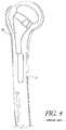
- FIG. 4is a side view of a humeral bone and implant illustrating stem fracture.
- FIG. 5Ais a side view of a prior art implant illustrating a unique head orientation of a proximal portion thereof.
- FIG. 5Bis a side view of another prior art implant illustrating a unique head orientation of a proximal portion thereof.
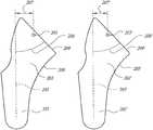
- FIG. 6Ais a side view of an embodiment of a humeral stem having certain features and advantages according to the present inventions.
- FIG. 6Bis a side view of another embodiment of a humeral stem having certain features and advantages.
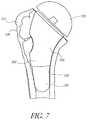
- FIG. 7is a side view of a humeral stem positioned within a proximal humerus, according to another embodiment.
- FIG. 8is a schematic illustration of a proximal end of a broach, according to an embodiment.
- FIG. 9Aillustrates a humeral stem, according to another embodiment.
- FIG. 9Billustrates a femoral stem, according to another embodiment.
- FIG. 10Ais a side view of an embodiment of the stem wherein a proximal body portion thereof is oriented at an inclination angle with respect to a distal body portion thereof.
- FIG. 10Bis a side view of another embodiment of the stem wherein the proximal body portion is oriented at another inclination angle with respect to the distal body portion.
- FIG. 10Cis a side view of yet another embodiment of the stem wherein the proximal body portion is oriented at yet another inclination angle with respect to the distal body portion.
- FIG. 10Dis a side view of yet another embodiment of the stem wherein the proximal body portion is oriented at yet another inclination angle with respect to the distal body portion.
- FIG. 11Ais a side view of an implant of a system of implants wherein an inclination angle of the implant changes relative to a medial offset thereof, according to an embodiment.
- FIG. 11Bis a side view of another implant of the system, according to another embodiment.
- FIG. 11Cis a side view of yet another implant of the system, according to yet another embodiment.
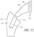
- FIG. 12shows how the broach can be inserted into the humerus.
- FIG. 13shows the broach when it is fully inserted to the correct size marking.
- FIG. 14shows a stem with a shortened distal region.
- FIG. 15shows how a reamer is inserted into a broached humeral cavity.
- FIG. 16shows how the broach is guided by the conforming proximal humerus.
- FIG. 17shows an instrument that combines a broach and a reamer.
- a stemis a broad term that is used to designate a device that is implanted into the bone for the purpose of supporting a functional component of a joint replacement and resisting the loads applied to the functional component.
- a stemcan be a device implanted into a humerus or femur to support a modular prosthetic humeral or femoral head (i.e. the supported structure).
- the supported structurecan be an integral part of the stem, as with a monolithic stem and head.
- Femoral and humeral stemstypically include distal and proximal sections as well as a taper or other coupling device to which the functional component is attached.
- femoral stemstypically include a neck section that extends the distance between the proximal section and the head.
- the neckis not embedded in the bone, but sits proud.
- neckcan refer to the portion of a femoral stem that does not reside within the femur bone, and extends the distance between the proximal body and the head.
- proximal bodycan refer to the portion of the humeral or femoral stem that resides within the bone and is nearer to the head (more proximal).
- the proximal limit of the proximal bodyis typically denoted by the resection plane or coupling device.
- the distal limit of the proximal bodyis typically denoted by a transition from a substantially diverging shape to a slightly diverging or substantially elongated shape. These shapes are intended to somewhat mimic the shapes of the bone in their corresponding locations.
- distal regioncan refer to the portion of the humeral or femoral stem that resides in the bone and is farther from the head.
- the proximal limit of the distal regionis typically denoted by a transition from a slightly diverging or substantially elongated shape, to a substantially diverging shape. These shapes are intended to somewhat mimic the shapes of the bone in their corresponding locations.
- distal stem anglecan refer to the angle between the best fit central axis of the distal region of the stem and the resection plane.
- the term “cavity”can refer to the entire prepared hole in which the stem will be implanted.
- centrala proximal location is implied because the distal humerus and femur are very elongated distally and consequently dictate central placement.
- the term “bone canal”can refer to the portion of the humerus or femur that is substantially elongated and accepts the distal region of the stem.
- the proximal limit of the distal regionis typically denoted by a transition from a slightly diverging or substantially elongated shape, to a substantially diverging shape.
- the term “broach”can refer to a bonecutting tool comprising a series of progressively taller points mounted on a single piece of metal, typically used to enlarge a circular hole into a larger noncircular shape such as a square or other desired shape.
- the amount of material removed by each broach tooth (or chisel)varies with the material being cut.
- a broachalso may also be designed to be pushed or pulled through an existing hole.
- the term “broaching” as used herein,can refer to this bone-removal process.
- the term “reaming”can refer to a process whereby a hole is enlarged to an accurate size. Although generally reaming must be preceded by a drilling or boring operation, that is not true in embodiments disclosed herein, for example, where the starting material is a hole or other shape that is being cleaned up. Reaming can also be performed on surfaces such as a sphere or other concave or convex surfaces as it is when a glenoid is reamed with a spherical reamer.
- the term “resect,” “resecting,” or “resection” as used hereincan refer to a process whereby a portion of a structure is cut off or cut out.
- subjectas used herein includes animals of mammalian origin, including humans.
- the head endis referred to as the cranial end
- the tail endis referred to as the caudal end.
- rostralcan refer to the direction toward the end of the nose
- caudalis used to refer to the tail direction.
- proximalOn the limbs or other appendages, a point closer to the joint contact is “proximal”; a point farther away is “distal.” This principle shall be followed in relation to embodiments of the apparatuses disclosed herein; a point closer to the main body of the apparatus shall be referred to as “proximal;” a point farther away shall be referred to as “distal.”
- a “sagittal” planedivides the body into left and right portions.
- the “midsagittal” planeis in the midline, i.e. it would pass through midline structures such as the spine, and all other sagittal planes are parallel to it.
- a “coronal” planedivides the body into dorsal and ventral portions.
- a “transverse” planedivides the body into cranial and caudal portions.
- a transverse, axial, or horizontal planeis an X-Y plane, parallel to the ground, which separates the superior/head from the inferior/feet.
- a corona] or frontal planeis an Y-Z plane, perpendicular to the ground, which separates the anterior from the posterior.
- a sagittal planeis an X-Z plane, perpendicular to the ground and to the corona] plane, which separates left from right.
- the midsagittal planeis the specific sagittal plane that is exactly in the middle of the body.
- Structures near the midlineare called medial and those near the sides of animals are called lateral. Therefore, medial structures are closer to the midsagittal plane, lateral structures are further from the midsagittal plane. Structures in the midline of the body are median. For example, the tip of a human subject's nose is in the median line.
- Ipsilateralmeans on the same side, contralateral means on the other side and bilateral means on both sides. Structures that are close to the center of the body are proximal or central, while ones more distant are distal or peripheral. For example, the hands are at the distal end of the arms, while the shoulders are at the proximal ends.
- a symmetric subjectis assumed when the terms “medial,” “lateral,” “inferior,” “superior,” “anterior,” and “posterior,” are used to refer to an implant.
- Embodiments disclosed hereinrelate to a method that can improve the positioning and fit of orthopedic reconstructive joint replacement implants.
- One of the goals in performing an orthopedic reconstructive joint replacementis to place a stem implant centrally within the bone and to provide good proximal fill. This not only more evenly loads the bone, but also eliminates the need for head position adjustment.
- specific explanationswill refer to either the shoulder (humerus) or the hip (femur), the methods disclosed herein are mutually exclusive and can be used alone or in combination as a general method for reconstructing joints.
- FIG. 1a prior art stem implant 10 that is implanted into a humerus bone 12 is shown.
- a head 14 of the humerus bone 12is resected in order to accommodate a tool (not shown) used to ream or broach a humeral canal 16 of the bone 12 in preparation for implantation.
- the humeral canal 16defines a best fit diameter.
- the humeral canal 16 of the humerus bone 12is then used as a guide to accept the stem implant 10 .
- the stem implant 10can include distal and proximal body portions 20 , 22 .
- the distal body portion 22 of the stem implant 10is inserted into the humeral canal 16 until the distal body portion 22 is tightly fitted into a distal area of the humeral canal 16 .
- the proximal body portion 20 or head portion of the stem implant 10is positioned in a proximal area 23 of the humeral canal 16 .
- the distal body portion 22is configured to form a tight fit with respect to the reamed humeral canal 16 , the canal 16 dictates the position of the distal body portion 22 and therefore, the position of the proximal body portion 20 of the implant 10 .
- the proximal body portion 20 of such prior art implantsdoes not fill the proximal area 23 of the humeral canal 16 , and causes detrimental reliance on distal stem geometry and fit, as described below.
- FIG. 2since the size, location, and orientation of the head portion 45 with respect to the humeral canal 16 vary greatly from person to person, a single stem geometry per size cannot accommodate natural placement or shape of the head portion 45 .
- proximal body portion 20An additional problem in the prior art is that the position and orientation of the proximal body portion 20 are governed by the distal area of the canal 16 , as shown in FIG. 3 . As such, the proximal body portion 20 must be made small enough to fit the smallest possible envelope within the proximal area of the humerus 12 . An excessively small proximal body portion 20 can cause poor proximal fixation of the implant 10 to the humerus 12 and lead to over-reliance on distal fixation of the implant 10 . Over time, when too much emphasis is placed on distal fixation, the strength of the proximal area of the bone 12 begins to deteriorate. This, as shown in FIG. 4 , can lead to loosening of the stem implant 10 and potentially fracture of the implant 10 .
- implants 50While some companies have tried to improve upon this model by offering different neck angles, such as with implants 50 having different configurations, as illustratively shown in FIGS. 5A-B . As illustrated, such implants 50 use the same geometry for the proximal body portion 52 and simply vary a resection angle 54 of the implant 50 . While this may improve placement of the head portion, it offers little to accommodate varying shapes of the proximal body portion 52 .
- an angle of a distal section of a stem implantcan be varied with respect to an entire proximal body instead of changing an angle of a resection cut or a neck. This means that, for different distal angles, the proximal body will move with respect to the humeral canal.
- the stem implant 100defines a proximal body 102 and a distal body 104 .
- the distal body 104 of the implant 100can be configured at a variety of angular orientations 106 ′, 106 ′′, 106 ′′′ relative to the proximal body 102 .
- the result, as shown in FIG. 6Bis that the proximal body 102 of the implant 100 can be configured at a variety of angular orientations 108 ′, 108 ′′, 108 ′′′ relative to the proximal body 102 .
- a plurality of implants 100can be provided to a surgeon such that the surgeon can select one of the implants 100 depending on the configuration required for the implant procedure.
- the surgeoncan be provided with a kit that comprises a variety of implants 100 with a variety of angular orientations 108 ′, 108 ′′, 108 ′′′ relative to the proximal body 102 .
- FIG. 7illustrates that the stem 100 can be selected based on the shape and sizing of the proximal body 102 and the angle of the humeral canal, which is accommodated with one of the implants 100 that provides the best fitting distal angle from a selection of multiple angles.
- the proximal body 102need not be fitted at a single orientation into the humerus bone 110 , the proximal body 102 can be larger and more conforming with a cortical portion 112 of the humerus bone 110 , thus providing better proximal fixation and bone loading.
- the proximal body 102is more conforming to the shape a cavity 118 of the humerus 110 , and the stem 100 will tend to center itself during insertion, accommodating proper placement of the stem 100 and potentially eliminating the need for offset adjustment of a head 120 of the stem 100 .
- stem sizes of embodiments disclosed hereincan be based on a continuous and progressive curvature.
- a single broach 130could be used to prepare the cavity 118 of the humerus 110 for multiple sizes, simply by adjusting the depth that the broach 130 is inserted.
- the prior art implants referred to abovecurrently require a different broach for each size, and in order to determine the proper size for use with a particular patient, one must experiment with multiple broaches, which can make it difficult to determine whether the next size is too large.
- an embodiment disclosed hereinprovides for a broach 130 having a progressive curvature.
- the broach 130can be used to prepare the cavity 118 of the bone 110 for implants 100 of any size.
- the broach 130can be configured to include a depth indicator 132 , which can comprise a plurality of markings 134 .
- a depth indicator 132can comprise a plurality of markings 134 .
- FIG. 9Aillustrates an embodiment of a stem implant 150 for use in a shoulder prosthesis.
- the implant 150can comprise: a distal section 152 (optional stems without the distal section 152 can be used); a proximal section 154 ; a resection plane or neck 156 ; and a coupling device 158 .
- various configurations of the implant 150can also be provided such that a surgeon can use a particularly configured implant 150 that suits the shape of the humeral cavity.
- Such variations in the implant 150can be performed by altering the angular orientation of the distal section 152 and the proximal section 154 with respect to each other.
- the distal section 152 of the implant 150can define a longitudinal axis 160 and the proximal section 154 of the implant 150 can define a neck axis 162 .
- various configurations of the implant 150can be designed with the longitudinal axis 160 of the distal section 152 being placed at a discrete angle 166 with respect to the neck axis 162 of the proximal section 154 .
- Additional embodiments of the implant 150can be configured with the longitudinal axis 162 of the distal section 152 being oriented at another discrete angle 168 with respect to the resection plane 156 .
- the angle 166can be varied while the angle 168 remains constant, and vice versa.
- prior art stemsvary the angle between the resection plane and the longitudinal axis by simply varying the resection angle.
- the angle between the resection plane and the longitudinal axisis varied by adjusting the angle between the distal section of the stem and the proximal section such that in certain embodiments the entire proximal section is pivoted about a point.
- the coupling device 158can be a tapered shape or other device for attachment of the humeral or femoral head.
- the term “tapered shape”can refer to a shape that is gradually narrower or thinner toward one end.
- the shape of the proximal portion 154 of the implant 150can curve medially to approximate the contours of the natural proximal humerus (as noted and illustrated above with respect to the embodiment shown in FIG. 7 ) and allow self-centered broaching.
- the hip stem implant 180can comprise: a distal section 182 (optional stems without the distal section 182 can be used); a proximal section 184 ; a resection plane or neck 186 ; and a coupling device 188 .
- various configurations of the implant 180can also be provided such that a surgeon can use a particularly configured implant 180 that suits the shape of the humeral cavity.
- Such variations in the implant 180can be performed by altering the angular orientation of the distal section 182 and the proximal section 184 with respect to each other.
- the distal section 182 of the implant 180can define a longitudinal axis 190 and the proximal section 184 of the implant 180 can define a neck axis 192 .
- various configurations of the implant 180can be designed with the longitudinal axis 190 of the distal section 182 being placed at a discrete angle 196 with respect to the neck axis 192 of the proximal section 184 .
- Additional embodiments of the implant 180can be configured with the longitudinal axis 190 of the distal section 182 being oriented at another discrete angle 198 with respect to the resection plane 186 .
- the angle 196can be varied while the angle 198 remains constant, and vice versa.
- the distal section 182is tapered.
- the coupling device 188can be a tapered shape or other device for attachment of the humeral or femoral head.
- the shape of the proximal portion 184 of the implant 180can curve medially to approximate the contours of the natural proximal humerus (as noted and illustrated above with respect to the embodiment shown in FIG. 7 ) and allow self-centered broaching.
- FIGS. 10A-Dillustrate an embodiment of a stem implant 200 comprising proximal and distal body portions 201 , 202 .
- the proximal body portion 201can be angularly oriented with respect to the distal body portion 202 at a plurality of angles, thus yielding a plurality of potential configurations of the stem implant, indicated as 200 , 200 ′, 200 ′′, and 200 ′′′.
- the proximal body portion 201can define a head center 203 and a resection plane 204 .
- the head center 203can lie in the resection plane 204 , and in particular, in a central location of the proximal body portion 201 in the resection plane 204 .
- the distal body portion 202can define a longitudinal axis 205 that is oriented at an inclination angle 206 with respect to the resection plane 204 .
- the head center 203 and the longitudinal axis 205are spaced apart at a medial offset 207 .
- the medial offset 207can be the distance between the head center 203 of the proximal body portion 201 and a closest point along the longitudinal axis 205 . If illustrated graphically, the medial offset 207 would be the length of a line oriented perpendicularly to the longitudinal axis 205 and extending between the head center 203 and the longitudinal axis 205 . Therefore, in accordance with a preferred embodiment, the stem implant 200 can be configured such that the inclination angle 206 remains constant while the medial offset 207 varies.
- the medial offset 207can be between approximately 4 mm and approximately 15 mm, and is preferably between approximately 5 mm to approximately 11 mm.
- a plurality of implants 200such as four, can be provided, and that the implants can have medial offsets of approximately 5 mm, approximately 7 mm, approximately 9 mm, and approximately 11 mm, respectively. Accordingly, each implant would have a different medial offset, but all of the implants could have the same inclination angle.
- Other embodiments and combinationscan be created by one of skill utilizing these teachings.
- FIGS. 11A-Cillustrate a system of implants 200 ′, 200 ′′, and 200 ′′′. As similarly described with respect to the embodiment shown in FIG.
- each of the implants 200 ′, 200 ′′, and 200 ′′′can include proximal and distal body portions 201 ′, 201 ′′, 201 ′′′ and 202 ′, 202 ′′, 202 ′′′, respectively, as well as medial offsets 207 ′, 207 ′′, 207 ′′′ defined as the distance between head centers 203 ′, 203 ′′, 203 ′′′ of the respective ones of the proximal body portions 201 ′, 201 ′′, 201 ′′′ and longitudinal axes 205 ′, 205 ′′, 205 ′′′ of the respective ones of the distal body portions 202 ′, 202 ′′, 202 ′′′.
- FIGS. 11A-Cillustrate an embodiment of a system of implants 200 ′, 200 ′′, 200 ′′′ wherein the medial offsets 207 ′, 207 ′′, 207 ′′′ change as a function of inclination angle 206 ′, 206 ′′, 206 ′′′, respectively.
- the medial offset 207 ′is approximately 12 mm while the inclination angle 206 ′ is approximately 45 degrees.
- the medial offset 207 ′′is approximately 8 mm while the inclination angle 206 ′′ is approximately 41 degrees.
- the medial offset 207 ′′′is approximately 5 mm while the inclination angle 206 ′′′ is approximately 37 degrees. These measurements are those of exemplary embodiments for purposes of illustration only. It is contemplated that the medial offset can be in the range of approximately 4 mm to approximately 15 mm, and that the inclination angle can be in the range of approximately 30 degrees to approximately 55 degrees.
- FIGS. 12-13an embodiment of a procedure will be described for preparing a humeral cavity 210 of a humerus bone 212 and implanting the stem into the prepared cavity 210 .
- an initial or pilot hole 216may be drilled in the center of the resected head.
- a broach 220can then be inserted through a central area of the resection surface 214 , through the pilot hole 216 , and driven into the humerus 212 with a mallet or other impaction device.
- the broach 220As the broach 220 is being driven in, it is guided by a proximal area 222 of the humerus bone 212 .
- the broach 220can be configured for use with multiple sizes, and a depth indicator 224 , such as graduations, marking, or other visual or physical devices used on or with the broach 220 .
- a depth indicator 224such as graduations, marking, or other visual or physical devices used on or with the broach 220 .
- the depth indicator 224can illustrate the depth or distance required to further insert the broach 220 in order to reach a given stem implant size, as illustrated in FIG. 13 .
- the sizing of a proximal body 226 of the broach 220can be configured such that it increases in size in the proximal direction. Such increases in size can be progressive, if desired, depending on the geometry of the implants being used. Thus, one broach 220 could be used to prepare the cavity 210 for an implant of small size or of large size, depending on how much of the proximal body 226 of the broach 220 is inserted to within the bone 212 during preparation. Because of this, a single broach 220 can be used to prepare a cavity 210 for several sizes simply by changing the depth of insertion. This will make it very simple for a surgeon to determine the proper size. For example, if the broach is inserted for a size 3, the depth indicator 224 can show the location for a size such that the difference in insertion depth is clearly illustrated.
- the surgeonmay trial one or many implants to determine what size of the distal portion of the implant is necessary. If the surgeon feels that stem stability will be sufficient without the distal portion, he/she may opt to stop the preparation of the cavity 210 at that point and implant a short stem. Thus, the surgeon can exercise caution and discretion in incrementally reaming the cavity 210 so that a stem 230 with a shorter distal portion 232 can be used if desired, as shown in FIG. 14 .
- the next stepis to ream the canal 210 of the humerus 212 using a tapered or cylindrical reamer 240 .
- the reamer 240is inserted into the humeral canal 210 at a base 242 of the cavity 210 and reamed to a desired depth. Once the canal 210 has been reamed to its proper depth, a trial of the reamer 240 can be used to determine which of the angled stems is needed, and the stem can then be implanted.
- the humeral canalmust be reamed if a stem with a distal section is to be used.
- the angle of the stem of the certain embodimentscan be adjusted by varying the angle of the distal section with respect to the proximal body. Because of this, instead of fitting the stem to the humeral canal and forcing a non-conforming proximal body to be poorly placed in the humerus, a conforming proximal body can be fit to the proximal humerus and different distal stem angles can be used to fit the canal.
- a set of stemscan be provided that have three discrete stem angles of approximately 35, approximately 40, and approximately 45 degrees (as measured between the longitudinal axis and the resection plane, discussed in FIGS. 9A-B ). Alternate embodiments comprising more angles and/or a wider range also may be used. With a five degree interval between angles, a maximum 2.5 degree mismatch could exist between the stem distal angle and the humeral canal; however, such a mismatch could still allow proper placement of the stem. In some embodiments, the distal portions of the reamer and the stem implant can be tapered to help accommodate this difference.
- a broach 250can be configured to have a medial curve/surface 252 and a lateral curve/surface 254 that are configured to provide the broach 250 with a shape that facilitates proper alignment of the stem 250 within a cavity 256 of a bone 258 such that the broach 250 can be centered within a cortical portion 260 of the bone 258 .
- the medial curve 252and to a somewhat lesser extent, the lateral curve 254 , can be designed to mimic the general shape of the proximal area of the humerus 258 .
- the broach 250will want to follow the path of least resistance, which will be through the weakest bone at the center of the humerus 258 and not through the cortical portion 260 thereof.
- the final resultis that a proximal body 262 of the broach 250 can be placed in the center of a resected surface 264 of the humerus 258 regardless of its position with respect to the humeral canal 256 .
- proximal bodies 262 of large sizescan be used and that they will be supported by more structural bone than a traditional humeral stem. Since the proximal body 262 can be placed essentially in the center of the humerus 258 , little or no adjustment of the proximal portion 262 will be required.
- a reamer guidecould be placed into the prepared proximal cavity to eliminate any angular mismatch between sizes instead of reaming using the canal for guidance.
- more angled stemscould be added to reduce the potential for mismatch.
- the humeral canalcould be reamed and the proximal cavity could be broached using the reamer for guidance, instead of broaching before reaming. While this could somewhat influence proximal stem placement, the benefit of multiple distal angles would still vastly improve placement and fill over current stems.
- curves that mimic the proximal body shapecould be used in areas other than the medial and lateral curves/surfaces. They could be placed anterior and posterior or at any number of regular intervals around the stem.
- the distal stem shapecould also have a local increase in size at its tip (such as, but not limited to, a ball on the end of the distal section). This would help accommodate any mismatch between the distal section and the reamed humeral canal. The distal increase would contact the reamed cavity and the gap after the increase would allow the distal stem center to vary slightly from the humeral canal center.
- the shape of the distal section of the stem and/or reamercan be cylindrical, elliptical, or irregularly shaped instead of being tapered.
- ellipticalcan refer to a shape that resembles an elongated or flattened circle
- cylindricalcan refer to a shape that is round in cross section, and equally wide throughout its length
- intraregularly shapedcan refer to a shape that does not vary consistently in shape or size, for example, a distal region that is substantially tapered, but has one area that has a significantly increased size.
- the shape of the distal section of the stem and/or reamercan incorporate any grooves, slots, or cutouts for flexibility, fit, or fixation.
- the term “groove”can refer to an elongated channel in the distal region of the stem. These grooves are typically narrow and distributed around the distal region at close intervals, creating narrow raised ridges between them. When inserted with slight interference with the bone, these ridges can embed themselves within the bone, providing mechanical locking and allowing a tight fit with some mismatch in shape between the canal and the distal region.
- the term “slot”can refer to an elongated opening in the distal region of the stem placed to increase the flexibility of that portion of the stem.
- a single slotcan extend through the entire thickness of the distal region of the stem, dividing it in two. If multiple slots are used, they can intersect and end near the central axis of the distal region of the stem, dividing the distal region in as many sections as there are slots.
- the term “cut out”can refer to a recess in the distal region of the stem that is meant to increase the flexibility of that portion of the stem. These cutouts are typically on one or more sides of distal region of the stem and are placed around the periphery, not through the center.
- the entire cavitycould be prepared by broaching instead of by broaching and then reaming.
- the cavitycould be broached first and then reamed using a reamer that was guided by the broach or ream first and use a broach that was guided by the reamer instead of broaching and reaming independently.
- an instrument 300is provide that incorporates a reaming section 302 and a broaching section 304 that are coupled together with a handle or driving member 306 .
- the reaming section 302can be disposed at a distal end of the instrument 300 and be used to ream the bone for preparation thereof for implantation.
- the broaching section 304can incorporate a broach and be disposed intermediate the reaming section 302 and the handle 306 , such that during use, after the reaming section 302 has reamed the cavity of the bone, the instrument 300 can continue to be driven into the bone such that the broaching section 304 can be used to broach a proximal portion of the cavity.
- a single toolcan be used to perform both of the broaching and reaming operations in preparation for implantation of a stem.
- the instrument 300can incorporate a joint 310 that would allow for slight angular adjustments of the orientation of the reaming section 302 relative to the broaching section 304 .
- the distal region of the stemcould be angled in the anterior/posterior direction as well as the medial/lateral direction,
- the neck of the stemcould be made modular, such that a given stem would accept multiple necks that would be fixed to the stem using a taper or other locking mechanism.
Landscapes
- Health & Medical Sciences (AREA)
- Life Sciences & Earth Sciences (AREA)
- Surgery (AREA)
- Orthopedic Medicine & Surgery (AREA)
- Veterinary Medicine (AREA)
- Public Health (AREA)
- Oral & Maxillofacial Surgery (AREA)
- Engineering & Computer Science (AREA)
- Biomedical Technology (AREA)
- Heart & Thoracic Surgery (AREA)
- General Health & Medical Sciences (AREA)
- Animal Behavior & Ethology (AREA)
- Molecular Biology (AREA)
- Medical Informatics (AREA)
- Nuclear Medicine, Radiotherapy & Molecular Imaging (AREA)
- Dentistry (AREA)
- Cardiology (AREA)
- Transplantation (AREA)
- Vascular Medicine (AREA)
- Prostheses (AREA)
Abstract
Description
Claims (20)
Priority Applications (2)
| Application Number | Priority Date | Filing Date | Title |
|---|---|---|---|
| US15/250,606US10898336B2 (en) | 2006-03-21 | 2016-08-29 | Femoral and humeral stem geometry and implantation method for orthopedic joint reconstruction |
| US17/149,527US20210128310A1 (en) | 2006-03-21 | 2021-01-14 | Femoral and humeral stem geometry and implantation method for orthopedic joint reconstruction |
Applications Claiming Priority (3)
| Application Number | Priority Date | Filing Date | Title |
|---|---|---|---|
| US78423606P | 2006-03-21 | 2006-03-21 | |
| US11/689,470US20070225821A1 (en) | 2006-03-21 | 2007-03-21 | Femoral and humeral stem geometry and implantation method for orthopedic joint reconstruction |
| US15/250,606US10898336B2 (en) | 2006-03-21 | 2016-08-29 | Femoral and humeral stem geometry and implantation method for orthopedic joint reconstruction |
Related Parent Applications (1)
| Application Number | Title | Priority Date | Filing Date |
|---|---|---|---|
| US11/689,470ContinuationUS20070225821A1 (en) | 2006-03-21 | 2007-03-21 | Femoral and humeral stem geometry and implantation method for orthopedic joint reconstruction |
Related Child Applications (1)
| Application Number | Title | Priority Date | Filing Date |
|---|---|---|---|
| US17/149,527ContinuationUS20210128310A1 (en) | 2006-03-21 | 2021-01-14 | Femoral and humeral stem geometry and implantation method for orthopedic joint reconstruction |
Publications (2)
| Publication Number | Publication Date |
|---|---|
| US20160361173A1 US20160361173A1 (en) | 2016-12-15 |
| US10898336B2true US10898336B2 (en) | 2021-01-26 |
Family
ID=38523099
Family Applications (3)
| Application Number | Title | Priority Date | Filing Date |
|---|---|---|---|
| US11/689,470AbandonedUS20070225821A1 (en) | 2006-03-21 | 2007-03-21 | Femoral and humeral stem geometry and implantation method for orthopedic joint reconstruction |
| US15/250,606ActiveUS10898336B2 (en) | 2006-03-21 | 2016-08-29 | Femoral and humeral stem geometry and implantation method for orthopedic joint reconstruction |
| US17/149,527PendingUS20210128310A1 (en) | 2006-03-21 | 2021-01-14 | Femoral and humeral stem geometry and implantation method for orthopedic joint reconstruction |
Family Applications Before (1)
| Application Number | Title | Priority Date | Filing Date |
|---|---|---|---|
| US11/689,470AbandonedUS20070225821A1 (en) | 2006-03-21 | 2007-03-21 | Femoral and humeral stem geometry and implantation method for orthopedic joint reconstruction |
Family Applications After (1)
| Application Number | Title | Priority Date | Filing Date |
|---|---|---|---|
| US17/149,527PendingUS20210128310A1 (en) | 2006-03-21 | 2021-01-14 | Femoral and humeral stem geometry and implantation method for orthopedic joint reconstruction |
Country Status (3)
| Country | Link |
|---|---|
| US (3) | US20070225821A1 (en) |
| EP (1) | EP1996124B1 (en) |
| WO (1) | WO2007109340A2 (en) |
Cited By (1)
| Publication number | Priority date | Publication date | Assignee | Title |
|---|---|---|---|---|
| US11679006B2 (en) | 2011-10-31 | 2023-06-20 | Tornier Orthopedics Ireland, Ltd. | Systems for shoulder prostheses |
Families Citing this family (49)
| Publication number | Priority date | Publication date | Assignee | Title |
|---|---|---|---|---|
| US7887544B2 (en) | 2003-03-10 | 2011-02-15 | Tornier Sas | Ancillary tool for positioning a glenoid implant |
| FR2863865B1 (en) | 2003-12-19 | 2006-10-06 | Tornier Sa | SHOULDER OR HIP PROSTHESIS AND METHOD OF MOUNTING |
| FR2871371B1 (en) | 2004-06-15 | 2007-04-06 | Tornier Sas | GLENOIDAL COMPONENT OF SHOULDER PROSTHESIS, SET OF COMPONENT ELEMENTS OF SUCH COMPONENT AND TOTAL SHOULDER PROSTHESIS INCORPORATING SUCH COMPONENT |
| US7678150B2 (en) | 2004-06-15 | 2010-03-16 | Tornier Sas | Total shoulder prosthesis of an inverted type |
| US8303665B2 (en) | 2004-06-15 | 2012-11-06 | Tornier Sas | Glenoidal component, set of such components and shoulder prosthesis incorporating such a glenoidal component |
| FR2872025B1 (en) | 2004-06-28 | 2006-08-25 | Tornier Sas | PROSTHESIS OF SHOULDER OR HIP |
| EP1996123B1 (en) | 2006-03-21 | 2019-08-28 | Tornier, Inc. | Non-spherical articulating surfaces in shoulder and hip prosthesis |
| WO2007109319A2 (en) | 2006-03-21 | 2007-09-27 | Axiom Orthopaedics, Inc. | Glenoid component with improved fixation stability |
| WO2007109340A2 (en) | 2006-03-21 | 2007-09-27 | Axiom Orthopaedics, Inc. | Femoral and humeral stem geometry and implantation method for orthopedic joint reconstruction |
| FR2899790B1 (en)* | 2006-04-13 | 2008-06-13 | Tornier Sas | GLENOIDAL COMPONENT FOR TOTAL SHOULDER PROSTHESIS, SET OF SUCH COMPONENTS, AND TOTAL SHOULDER PROSTHESIS COMPRISING SUCH A COMPONENT |
| FR2900045B1 (en) | 2006-04-21 | 2009-01-16 | Tornier Sas | PROSTHESIS OF SHOULDER OR HIP |
| FR2911773B1 (en) | 2007-01-30 | 2009-03-27 | Tornier Sas | METHOD AND ASSEMBLY OF SURGICAL INSTRUMENTATION FOR POSITIONING A TOTAL REVERSE SHOULDER PROSTHESIS, AND CORRESPONDING PROSTHESIS |
| US20090287309A1 (en) | 2007-01-30 | 2009-11-19 | Tornier Sas | Intra-articular joint replacement |
| US20100262254A1 (en)* | 2009-04-09 | 2010-10-14 | Solana Surgical LLC | Metatarsal bone implant |
| US9512445B2 (en) | 2009-08-31 | 2016-12-06 | The Cleveland Clinic Foundation | Humeral joint replacement component |
| DE102010000419A1 (en)* | 2009-12-23 | 2011-06-30 | Aesculap AG, 78532 | Modular denture rasp |
| US9408652B2 (en) | 2010-04-27 | 2016-08-09 | Tornier Sas | Intra-articular joint replacement and method |
| FR2961684B1 (en)* | 2010-06-25 | 2013-04-26 | T O | SET OF SURGICAL INSTRUMENTS FOR PREPARING A FEMORAL FUTURE |
| CN103153240B (en) | 2010-08-16 | 2017-02-15 | 史密夫和内修有限公司 | Patient-matched acetabular alignment tool |
| FR2966343B1 (en) | 2010-10-22 | 2012-12-07 | Tornier Sa | SET OF GLENOIDIAN COMPONENTS OF SHOULDER PROSTHESIS |
| FR2972627B1 (en)* | 2011-03-18 | 2013-03-22 | Fx Solutions | HUMERAL ROD OF SHOULDER PROSTHESIS, AND ASSEMBLY FORMED THEREBY AND BY A RECONSTRUCTION ELEMENT SUITABLE TO BE ASSEMBLED THEREBY |
| WO2013102089A1 (en) | 2011-12-30 | 2013-07-04 | Howmedica Osteonics Corp. | Systems for preparing bone voids to receive a prosthesis |
| CA2907537C (en) | 2012-08-01 | 2020-08-25 | Exactech, Inc. | Prosthetic devices to improve joint mechanics in arthroplasty |
| US9320603B2 (en) | 2012-09-20 | 2016-04-26 | Depuy (Ireland) | Surgical instrument system with multiple lengths of broaches sharing a common geometry |
| US9532879B2 (en) | 2012-09-20 | 2017-01-03 | Depuy Ireland Unlimited Company | Femoral knee prosthesis system with augments and multiple lengths of sleeves sharing a common geometry |
| BR112015007174A8 (en) | 2012-10-29 | 2018-04-24 | Tornier Orthopedics Ireland Ltd | Modular reverse shoulder prosthesis and respective systems |
| US9526513B2 (en) | 2013-03-13 | 2016-12-27 | Howmedica Osteonics Corp. | Void filling joint prosthesis and associated instruments |
| US10433969B2 (en) | 2013-12-30 | 2019-10-08 | United Orthopedic Corp. | Arthroplasty implants and methods for orienting joint prosthesis |
| US9962266B2 (en) | 2015-09-11 | 2018-05-08 | Deltoid, Llc | Arthroplasty components |
| US9956083B2 (en) | 2013-12-30 | 2018-05-01 | Deltoid, Llc | Instruments and techniques for orienting prosthesis components for joint prostheses |
| US9681960B2 (en) | 2014-05-16 | 2017-06-20 | Howmedica Osteonics Corp. | Guides for fracture system |
| US10575968B2 (en) | 2014-05-16 | 2020-03-03 | Howmedica Osteonics Corp. | Guides for fracture system |
| DE102014012853B3 (en)* | 2014-09-03 | 2015-10-29 | Implantec Deutschland Gmbh | Set with a number of hip stem implants |
| FR3029769A1 (en) | 2014-12-10 | 2016-06-17 | Tornier Sa | KIT FOR A PROSTHESIS OF SHOULDER |
| US10149763B2 (en) | 2015-01-12 | 2018-12-11 | Howmedica Osteonics Corp. | Multipurpose void filling prosthesis |
| DE102016100312B3 (en) | 2016-01-11 | 2017-04-06 | Aesculap Ag | Medical Instrument |
| EP3445292B1 (en) | 2016-04-19 | 2022-12-21 | Imascap SAS | Pre-operatively planned humeral implant and planning method |
| US10575781B2 (en) | 2016-05-24 | 2020-03-03 | AOD Holdings, LLC. | Hip broach with embedded sensor and a feedback broach system |
| EP4233740A3 (en) | 2016-08-24 | 2023-09-27 | Howmedica Osteonics Corp. | Humeral head implant system |
| WO2018183484A1 (en) | 2017-03-31 | 2018-10-04 | Tornier, Inc. | Modular humeral head |
| US10893874B2 (en) | 2017-08-15 | 2021-01-19 | Howmedica Osteonics Corp. | Instruments and methods for preparing a bone to receive a prosthesis |
| US12370052B2 (en) | 2018-10-02 | 2025-07-29 | Howmedica Osteonics Corp. | Modular humeral head |
| US11931264B2 (en) | 2018-10-02 | 2024-03-19 | Howmedica Osteonics Corp. | Modular humeral head |
| WO2020144651A2 (en)* | 2019-01-10 | 2020-07-16 | Synthes Gmbh | Surgical instrument handle with implant sizing feature and method of using |
| US11224517B2 (en) | 2019-06-26 | 2022-01-18 | DePuy Synthes Products, Inc. | Mechanically coupled revision hip system and method |
| CN110338943B (en)* | 2019-07-17 | 2023-11-24 | 天津市天津医院 | Computer aided design individuation humerus prosthesis and manufacturing method |
| USD938590S1 (en) | 2019-10-01 | 2021-12-14 | Howmedica Osteonics Corp. | Humeral implant |
| AU2021202801A1 (en) | 2020-05-07 | 2021-11-25 | Howmedica Osteonics Corp. | Stemless metaphyseal humeral implant |
| US20240138854A1 (en) | 2022-11-02 | 2024-05-02 | Zimmer, Inc. | Universal broach system for humeral implants |
Citations (327)
| Publication number | Priority date | Publication date | Assignee | Title |
|---|---|---|---|---|
| CH426096A (en) | 1965-01-29 | 1966-12-15 | Maurice E Prof Dr Med Mueller | Hip joint prosthesis |
| CH507704A (en) | 1969-03-05 | 1971-05-31 | Osteo Ag Arzt Und Krankenhausb | Femoral head prosthesis |
| US3694820A (en) | 1969-08-25 | 1972-10-03 | Nat Res Dev | Prosthetic shoulder joint |
| US3815157A (en) | 1971-11-30 | 1974-06-11 | Nat Res Dev | Prosthetic shoulder joint devices |
| US3842442A (en) | 1972-09-04 | 1974-10-22 | Nat Res Dev | Endoprosthetic shoulder joint |
| US3864758A (en) | 1973-08-31 | 1975-02-11 | Sam Savo Yakich | Hip joint bearing prosthesis |
| US3869730A (en) | 1973-07-25 | 1975-03-11 | Barry A Skobel | Surgically implantable joint prosthesis |
| FR2248820A1 (en) | 1973-10-29 | 1975-05-23 | Benoist Girard & Cie | Complete artificial joint between bones - has interlocked rings permanently attached together |
| US3916451A (en) | 1974-10-25 | 1975-11-04 | Frederick F Buechel | Floating center prosthetic joint |
| US3978528A (en) | 1975-06-26 | 1976-09-07 | Howmedica, Inc. | Bone and joint prosthesis |
| US3979778A (en) | 1976-01-14 | 1976-09-14 | Stroot Jerome H | Shoulder prosthesis |
| US3992726A (en) | 1974-08-07 | 1976-11-23 | National Research Development Corporation | Endoprosthetic bone joint devices |
| US4003095A (en) | 1976-04-29 | 1977-01-18 | Howmedica, Inc. | Trispherical prosthetic shoulder device |
| US4030143A (en) | 1975-01-31 | 1977-06-21 | National Research Development Corporation | Endoprosthetic bone joint devices |
| US4054955A (en) | 1976-01-29 | 1977-10-25 | Arnold Ivanovich Seppo | Orthopaedic endoapparatus designed to grow a new live shoulder and hip joint, to reconstruct a deformed joint or to restore a pathologically dysplastic and congenitally luxated joint |
| GB1504055A (en) | 1975-06-02 | 1978-03-15 | English T | Femoral prosthesis |
| US4135517A (en) | 1977-07-21 | 1979-01-23 | Minnesota Mining And Manufacturing Company | Femoral prosthesis trial fitting device |
| US4179758A (en) | 1976-04-29 | 1979-12-25 | Howmedica, Inc. | Fixation stem for prosthetic device |
| US4206517A (en) | 1977-12-01 | 1980-06-10 | Biomedical Engineering Corp. | Floating center prosthetic joint |
| SU749392A1 (en) | 1978-06-02 | 1980-07-23 | Ворошиловградский государственный медицинский институт | Arm joint endoprothesis |
| US4261062A (en) | 1979-03-22 | 1981-04-14 | The Regents Of The University Of California | Natural shoulder joint prosthesis |
| US4310931A (en)* | 1979-10-11 | 1982-01-19 | Gebruder Sulzer A.G. | Hip joint prosthesis |
| FR2545352A1 (en) | 1983-05-02 | 1984-11-09 | Gabard Jean Jacques | SHOULDER PROSTHESIS |
| US4550450A (en) | 1984-07-24 | 1985-11-05 | Kinnett James G | Total shoulder prosthesis system |
| FR2574283A1 (en) | 1984-12-07 | 1986-06-13 | Tornier Sa | Prosthesis for the neck of the femur with eccentric ball |
| EP0257359A1 (en) | 1986-08-15 | 1988-03-02 | Boehringer Mannheim Corporation | Modular hip prosthesis |
| US4795471A (en) | 1982-01-18 | 1989-01-03 | Indong Oh | Conversion femoral endoprosthesis |
| EP0299889A2 (en) | 1987-07-15 | 1989-01-18 | Universite De Bourgogne (U.F.R. De Medecine) | Total shoulder prosthesis |
| US4822370A (en) | 1986-01-14 | 1989-04-18 | Orthoplant Endoprothetik | Hip joint femoral prosthesis |
| US4846840A (en) | 1986-09-09 | 1989-07-11 | Sylvain Leclercq | Joint prosthesis |
| US4865605A (en) | 1988-02-02 | 1989-09-12 | Dines David M | Modular shoulder prosthesis |
| US4865609A (en) | 1988-03-02 | 1989-09-12 | Bioconcepts, Inc. | Modular joint prosthesis assembly and method of removing |
| US4892549A (en) | 1989-01-31 | 1990-01-09 | Osteonics Corp. | Dual-radius acetabular cup component |
| US4919670A (en) | 1988-02-03 | 1990-04-24 | Intermedics Orthopedics, Inc. | Modular humeral prosthesis |
| US4957510A (en) | 1987-08-03 | 1990-09-18 | Patrizio Cremascoli | Hip prosthesis structure adapted for easy fitting to the patient coxo-femural articulation |
| US4963155A (en) | 1989-08-30 | 1990-10-16 | Zimmer, Inc. | Attachment mechanism for modular surgical products |
| FR2652498A1 (en) | 1989-10-04 | 1991-04-05 | Medinov | Modular assembly for a shoulder prosthesis |
| WO1991007932A1 (en) | 1989-11-30 | 1991-06-13 | Ab Volvo | Artificial hip-joint |
| US5032132A (en) | 1990-01-22 | 1991-07-16 | Boehringer Mannheim Corporation | Glenoid component |
| US5080673A (en) | 1988-02-03 | 1992-01-14 | Intermedics Orthopedics, Inc. | Glenoid prosthesis and method of use |
| US5080685A (en) | 1986-08-15 | 1992-01-14 | Boehringer Mannheim Corporation | Modular hip prosthesis |
| FR2664809A1 (en) | 1990-07-19 | 1992-01-24 | Erato Ste Civile | Shoulder prosthesis system |
| US5108451A (en)* | 1991-01-31 | 1992-04-28 | Forte Mark R | Femoral component of a hip joint prosthesis |
| US5127920A (en) | 1987-03-27 | 1992-07-07 | Macarthur A Creig | Prosthesis and methods for subtotal dome arthroplasty of the hip joint |
| US5133760A (en) | 1990-02-12 | 1992-07-28 | Alvarado Orthopedic Research, Inc. | Universal modular prosthesis stem extension |
| US5135529A (en) | 1989-11-03 | 1992-08-04 | Dow Corning Wright Corporation | Instrument for implanting modular hip joint prosthesis with adjustable anteversion and method of using said instrument |
| US5163961A (en) | 1991-04-17 | 1992-11-17 | Harwin Steven F | Compression-fit hip prosthesis and procedures for implantation thereof |
| EP0524857A1 (en) | 1991-07-26 | 1993-01-27 | S.N.R. Roulements | Combined radial axial bearing |
| US5192329A (en) | 1991-03-07 | 1993-03-09 | Joint Medical Products Corporation | Oblong acetabular cup |
| US5201882A (en) | 1989-11-03 | 1993-04-13 | Paxson Robert D | Modular hip joint prosthesis with adjustable anteversion |
| US5206925A (en) | 1990-06-29 | 1993-04-27 | Hitachi Cable Limited | Rare earth element-doped optical waveguide and process for producing the same |
| WO1993009733A1 (en) | 1991-11-18 | 1993-05-27 | Depuy Inc. | Modular prosthesis |
| US5222984A (en) | 1990-03-15 | 1993-06-29 | Forte Mark R | Implantable acetabular prosthetic hip joint with universal adjustability |
| EP0549480A1 (en) | 1991-12-27 | 1993-06-30 | Etablissements TORNIER | Modular humeral prosthesis |
| US5261914A (en) | 1987-09-02 | 1993-11-16 | Russell Warren | Surgical fastener |
| EP0579868A2 (en) | 1992-07-24 | 1994-01-26 | HOWMEDICA INTERNATIONAL Div.ne PFIZER ITALIANA S.p.A. | Femoral rod for a complete hip prosthesis |
| US5314487A (en) | 1991-02-14 | 1994-05-24 | Smith & Nephew Richards Inc. | Acetabular prosthesis with anchoring pegs |
| EP0599429A2 (en) | 1992-11-26 | 1994-06-01 | Bristol-Myers Squibb Company | Femoral part of a hip joint endoprosthesis |
| FR2699400A1 (en) | 1992-12-18 | 1994-06-24 | Medinov Sa | Artificial shoulder prosthesis |
| US5330531A (en) | 1991-12-10 | 1994-07-19 | Howmedica Gmbh | Humeral endoprosthesis |
| EP0617934A1 (en) | 1993-03-30 | 1994-10-05 | LANDANGER-LANDOS, Société Anonyme | Head for a modular shoulder prosthesis |
| US5383936A (en) | 1992-09-26 | 1995-01-24 | Joachim Theusner | Artificial joint as an endoprosthesis for the human shoulder joint |
| US5425779A (en) | 1992-08-05 | 1995-06-20 | U.S. Medical Products, Inc. | Prosthetic implant for joint structures |
| EP0664108A2 (en) | 1994-01-24 | 1995-07-26 | ESKA Implants GmbH & Co. | Shoulder endoprosthesis |
| US5443519A (en) | 1993-04-22 | 1995-08-22 | Implex Corporation | Prosthetic ellipsoidal acetabular cup |
| US5462563A (en) | 1991-01-17 | 1995-10-31 | Minnesota Mining And Manufacturing Company | Orthopaedic implant |
| EP0679375A1 (en) | 1994-04-25 | 1995-11-02 | EUROS Société Anonyme | Modular prosthetic set for the shoulder joint |
| FR2721200A1 (en) | 1994-06-17 | 1995-12-22 | Cremascoli France | Hip prosthesis with variable articulation |
| US5507817A (en) | 1994-02-22 | 1996-04-16 | Kirschner Medical Corporation | Modular humeral prosthesis for reconstruction of the humerus |
| US5507824A (en) | 1993-02-23 | 1996-04-16 | Lennox; Dennis W. | Adjustable prosthetic socket component, for articulating anatomical joints |
| US5507818A (en) | 1994-06-30 | 1996-04-16 | Mclaughlin; John A. | Multipolar joint endoprosthesis |
| EP0712617A1 (en) | 1994-11-18 | 1996-05-22 | Tornier Sa | Spherical humeral prosthesis |
| FR2726994A1 (en) | 1994-11-17 | 1996-05-24 | Caffiniere Jean Yves De | Fixing cage for fractured upper end of humerus |
| EP0715836A1 (en) | 1994-12-08 | 1996-06-12 | CEDIOR S.a.r.L | Total shoulder endoprosthesis |
| WO1996017553A1 (en) | 1994-12-05 | 1996-06-13 | Wright Medical Technology, Inc. | A modular humeral prosthesis, and modular instrumentation for preparing a humerus for same, and a method for implanting same |
| US5549682A (en) | 1994-06-16 | 1996-08-27 | Roy; Stephen C. | Shoulder joint prosthesis with angular adjustment |
| DE19509037C1 (en) | 1995-03-14 | 1996-09-12 | Sq Services Ag | Humerus-head prosthesis for orthopaedic surgery |
| US5580352A (en) | 1990-06-06 | 1996-12-03 | Sekel; Ronald | Distal shaft with fast and slow screw threads |
| FR2737107A1 (en) | 1995-07-26 | 1997-01-31 | Medinov Sa | Assembly connection for two parts of joint prosthesis component - has connecting screw with enlarged head secured in female component by threaded locking washer and threaded shaft securing male component |
| EP0790044A2 (en) | 1996-02-13 | 1997-08-20 | Howmedica Inc. | Polyetheretherketone (peek) retaining ring for an acetabular cup assembly |
| EP0797694A1 (en) | 1994-12-12 | 1997-10-01 | Akzo Nobel N.V. | Solvent-spun cellulosic filaments |
| EP0807426A2 (en) | 1996-05-17 | 1997-11-19 | JOHNSON & JOHNSON PROFESSIONAL Inc. | Acetabular trial |
| EP0809986A2 (en) | 1996-05-28 | 1997-12-03 | Howmedica International Inc. | Tibial element for a replacement knee prosthesis |
| US5702447A (en) | 1995-11-30 | 1997-12-30 | Tornier S.A. | Device for the attachment of a glenoid prosthesis of the shoulder blade |
| DE19630298A1 (en) | 1996-07-26 | 1998-01-29 | Basim A Dr Fleega | Total shoulder arthroplasty |
| US5723018A (en) | 1992-11-17 | 1998-03-03 | Cyprien; Jean-Maxwell | Shoulder-joint endoprosthesis |
| US5728161A (en) | 1995-06-08 | 1998-03-17 | Depuy Orthopedics, Inc. | Large taper modular shoulder prosthesis |
| US5755807A (en) | 1996-06-17 | 1998-05-26 | Folsom Metal Products | Implant module unit and rotating seal for prosthetic joint |
| FR2758256A1 (en) | 1997-01-16 | 1998-07-17 | Aesculap Sa | Humeral prosthesis for orthopaedic rehabilitation |
| US5800551A (en) | 1997-03-10 | 1998-09-01 | Biomet, Inc. | Apparatus and method for shoulder arthroplasty |
| EP0864306A2 (en) | 1997-03-13 | 1998-09-16 | Zimmer Ltd | Prosthesis for knee replacement |
| WO1998046172A1 (en) | 1997-04-11 | 1998-10-22 | Smith & Nephew, Inc. | Modular humeral prosthesis |
| EP0898946A1 (en) | 1997-08-29 | 1999-03-03 | Stratec Medical S.A. | Humeral head prosthesis |
| US5879405A (en) | 1995-11-27 | 1999-03-09 | Smith & Nephew, Inc. | Acetabular cup body prosthesis |
| EP0903128A1 (en) | 1997-09-12 | 1999-03-24 | Tornier SA | Humeral prosthesis with indexed sphere |
| EP0903127A2 (en) | 1997-09-09 | 1999-03-24 | Howmedica Inc. | Anatomic glenoid shoulder prosthesis together with methods and tools for implanting same |
| US5902340A (en) | 1996-10-29 | 1999-05-11 | Hayes Medical, Inc. | Method of assembling a modular prosthesis used for bone replacement |
| US5910171A (en) | 1993-03-12 | 1999-06-08 | Hospital For Joint Diseases | Components for a modular shoulder and hip prosthesis |
| EP0927548A2 (en) | 1997-12-29 | 1999-07-07 | Johnson & Johnson Professional, Inc. | Acetabular prosthesis |
| FR2773469A1 (en) | 1998-01-09 | 1999-07-16 | Alain Leonard | SURGICAL EQUIPMENT FOR THE IMPLANTATION OF A TOTAL SHOULDER PROSTHESIS, AND TOTAL SHOULDER PROSTHESIS |
| US5928285A (en) | 1997-05-30 | 1999-07-27 | Bristol-Myers Squibb Co. | Orthopaedic implant having an articulating surface with a conforming and translational surface |
| EP0931522A1 (en) | 1998-01-16 | 1999-07-28 | Sulzer Orthopädie AG | Assembling set for shaft prostheses |
| US5944758A (en) | 1996-10-09 | 1999-08-31 | Minnesota Mining And Manufacturing Company | Shoulder prosthesis |
| US5961555A (en) | 1998-03-17 | 1999-10-05 | Huebner; Randall J. | Modular shoulder prosthesis |
| WO1999049792A1 (en) | 1998-04-01 | 1999-10-07 | Bionx Implants Oy | Bioabsorbable surgical fastener for tissue treatment |
| US5984927A (en) | 1998-03-03 | 1999-11-16 | Ethicon, Inc. | Device for sutureless attachment of soft tissue to bone |
| WO1999065413A1 (en) | 1998-06-13 | 1999-12-23 | Pfefferkorn & Co. Gmbh | Pressure element for exerting a pressure on a surface |
| US6015437A (en) | 1997-04-18 | 2000-01-18 | Headcorn Instrumentation Ltd. | Shoulder prosthesis |
| WO2000015154A1 (en) | 1998-09-11 | 2000-03-23 | Argomedical Ag | Implantable prosthesis having at least two sections which can be displaced in relation to one another, and the use of displaceable sections |
| US6045582A (en) | 1998-09-25 | 2000-04-04 | Sulzer Orthopedics Inc. | Implantable humeral shoulder prosthesis having extended articular surface |
| US6045583A (en) | 1997-03-25 | 2000-04-04 | Sulzer Orthopaedie Ag | Twin-shelled artificial hip joint and its manufacture |
| WO2000041653A1 (en) | 1999-01-11 | 2000-07-20 | Fenlin John M | Modular shoulder prosthesis system |
| US6129764A (en) | 1998-11-24 | 2000-10-10 | Stryker Technologies Corporation | Modular prosthetic joint components |
| EP1048274A2 (en) | 1999-01-29 | 2000-11-02 | Depuy Orthopaedics, Inc. | Shoulder prothesis with humeral fracture stem |
| WO2000074554A2 (en) | 1999-06-04 | 2000-12-14 | Depuy Orthopaedics, Inc. | Cartilage repair unit |
| US6165224A (en) | 1997-10-01 | 2000-12-26 | Tornier Sa | Prosthesis intended to be anchored in a long bone |
| EP1062923A2 (en) | 1999-06-23 | 2000-12-27 | Plus Endoprothetik Ag | Hip joint endoprostheses system |
| EP1064890A1 (en) | 1999-06-28 | 2001-01-03 | Aston Medical Limited | Prosthetic assembly for a shoulder joint |
| US6171341B1 (en) | 1996-08-02 | 2001-01-09 | Tornier Sa | Prosthesis for the upper extremity of the humerus |
| US6187012B1 (en) | 1999-07-08 | 2001-02-13 | Medidea, Llc | Prosthetic element removal apparatus and methods |
| EP1093777A2 (en) | 1999-10-22 | 2001-04-25 | Keramed Medizintechnik GmbH | Shoulder-endoprosthesis |
| US6228119B1 (en) | 1998-06-09 | 2001-05-08 | Depuy Orthopaedics, Inc. | Modular glenoid assembly |
| WO2001047442A1 (en) | 1999-12-23 | 2001-07-05 | Depuy France | Shoulder prosthesis assembly |
| US6267767B1 (en) | 1998-11-06 | 2001-07-31 | Karl Storz Gmbh & Co. Kg | Instrumentarium and method for implanting a cruciate ligament replacement in a knee joint |
| US20010011193A1 (en) | 2000-01-28 | 2001-08-02 | Cremascoli Ortho S.A. | Shoulder endoprosthesis for fractures of the upper end of the humerus |
| US20010032021A1 (en) | 2000-03-14 | 2001-10-18 | Mckinnon Brian W. | Variable geometry rim surface acetabular shell liner |
| US6312467B1 (en) | 1995-07-18 | 2001-11-06 | Iowa State University Research Foundation, Inc. | Method of restructuring bone |
| US20010041940A1 (en) | 1999-12-31 | 2001-11-15 | Pearl Michael L. | Modular shoulder prostheses |
| US20010047210A1 (en) | 2000-03-16 | 2001-11-29 | Wolf Eugene M. | Facile total shoulder arthroplasty apparatus and method |
| US6334874B1 (en) | 1999-06-09 | 2002-01-01 | Tornier Sa | Humeral prosthesis |
| US20020032484A1 (en) | 2000-06-13 | 2002-03-14 | Hyde Edward R. | Magnetic array implant and prosthesis |
| US6364910B1 (en) | 2001-07-11 | 2002-04-02 | Biomet, Inc. | Method and apparatus for use of a glenoid component |
| US6368353B1 (en) | 1999-02-24 | 2002-04-09 | Michel A. Arcand | Shoulder prosthesis apparatus and methods |
| EP1195149A2 (en) | 1998-05-22 | 2002-04-10 | Howmedica Osteonics Corp. | Acetabular cup assembly with selected bearing |
| US20020049502A1 (en) | 1998-08-20 | 2002-04-25 | Decarlo Alfred F. | Bone engaging prosthesis |
| WO2002039931A1 (en) | 2000-11-16 | 2002-05-23 | Willi Horber | Joint prosthesis |
| WO2002039933A1 (en) | 2000-11-16 | 2002-05-23 | Willi Horber | Endoprosthesis for a shoulder joint |
| US6398812B1 (en) | 2000-02-10 | 2002-06-04 | Medidea, Llc | Shoulder prosthesis with anatomic reattachment features |
| US6406495B1 (en) | 1998-12-22 | 2002-06-18 | Sulzer Orthopedics Ltd. | Glenoid prosthesis and a modular system with glenoid prostheses |
| US6406496B1 (en) | 1998-01-22 | 2002-06-18 | Sulzer Orthopedics Ltd. | Humerus head prosthesis |
| US20020099381A1 (en) | 2001-01-23 | 2002-07-25 | Maroney Brian J. | Method and apparatus for resecting a greater tubercle from a humerus of a patient during performance of a shoulder replacement procedure |
| US20020099445A1 (en) | 2001-01-23 | 2002-07-25 | Maroney Brian J. | Method and apparatus for performing a shoulder replacement procedure in the treatment of cuff tear arthropathy |
| US6436144B1 (en) | 1999-09-28 | 2002-08-20 | Aap Implantate Ag | Shoulder joint endoprosthesis |
| WO2002067821A2 (en) | 2001-02-21 | 2002-09-06 | New York Society For The Relief Of The Ruptured And Crippled Maintaining The Hospital For Special S Urgery | Dual-radius glenoid prosthetic component for total shoulder arthroplasty |
| US20020138148A1 (en) | 2001-01-16 | 2002-09-26 | Hyde Edward R. | Transosseous core approach and instrumentation for joint replacement and repair |
| US6458136B1 (en) | 2000-05-11 | 2002-10-01 | Zimmer, Inc. | Orthopaedic instrument for sizing implant sites and for pressurizing bone cement and a method for using the same |
| US20020143402A1 (en) | 1995-09-04 | 2002-10-03 | Limber Ltd. | Hip joint prostheses |
| US20020156534A1 (en) | 2001-04-19 | 2002-10-24 | Grusin N. Kelley | Modular humeral head with eccentric connector |
| US6494913B1 (en) | 1998-03-17 | 2002-12-17 | Acumed, Inc. | Shoulder prosthesis |
| US20030009171A1 (en) | 2001-07-09 | 2003-01-09 | Alain Tornier | Ancillary tool for fitting a humeral component of an elbow prosthesis |
| US6506214B1 (en) | 2000-05-02 | 2003-01-14 | R. Michael Gross | Method and means for cementing a liner onto the face of the glenoid cavity of a scapula |
| US6508840B1 (en) | 1999-04-07 | 2003-01-21 | Depuy Orthopaedis, Inc. | Collarless shoulder arthroplasty prosthesis |
| WO2003005933A2 (en) | 2001-07-11 | 2003-01-23 | Biomet, Inc. | Shoulder prosthesis |
| US6530957B1 (en) | 2001-08-23 | 2003-03-11 | Howmedica Osteonics Corp. | Modular joint prosthesis with multiple offset humeral head component and method |
| US20030097183A1 (en) | 2001-11-21 | 2003-05-22 | Markus Rauscher | Shoulder joint prosthesis |
| US6569202B2 (en) | 2001-04-02 | 2003-05-27 | Whiteside Biomechanics, Inc. | Tray and liner for joint replacement system |
| FR2835425A1 (en) | 2002-02-04 | 2003-08-08 | Tornier Sa | PROSTHETIC ELEMENT COMPRISING TWO COMPONENTS AND METHOD FOR ASSEMBLING SUCH A PROSTHETIC ELEMENT |
| FR2836039A1 (en) | 2002-02-15 | 2003-08-22 | Tornier Sa | GLENOIDAL COMPONENT OF SHOULDER PROSTHESIS AND TOTAL SHOULDER PROSTHESIS INCORPORATING SUCH COMPONENT |
| US20030171816A1 (en) | 2002-03-06 | 2003-09-11 | Christopher Scifert | Intramedullary trial fixation device |
| US6626946B1 (en) | 1996-06-25 | 2003-09-30 | Tornier Sa | Shoulder prosthesis and humeral stems for such a prosthesis |
| US6648894B2 (en) | 2000-12-21 | 2003-11-18 | Stryker Spine | Bone graft forming guide and method of forming bone grafts |
| WO2003094806A1 (en) | 2002-05-10 | 2003-11-20 | Ferree Bret A | Prosthetic components with cushioning elements |
| US6673114B2 (en) | 2000-05-03 | 2004-01-06 | Smith & Nephew, Inc. | Multi modular trialing system and instrumentation |
| US20040006392A1 (en) | 2001-04-19 | 2004-01-08 | Grusin N. Kelly | Prosthesis with compressible stem |
| EP1380274A1 (en) | 2002-07-05 | 2004-01-14 | Société Anonyme TORNIER | Shoulder or hip prosthetic for facilitating abduction |
| US6679916B1 (en) | 2002-04-29 | 2004-01-20 | Mark A. Frankle | Shoulder prosthesis system |
| US6702854B1 (en) | 1999-06-01 | 2004-03-09 | Apex Surgical, Llc | Implantable joint prosthesis |
| EP1402854A2 (en) | 2002-09-30 | 2004-03-31 | Depuy Products, Inc. | Reverse-type humeral prosthesis |
| US6719799B1 (en) | 1998-09-11 | 2004-04-13 | Argomedical Ag | Implantable prosthesis having at least two sections which can be displaced in relation to one another, and the use of displaceable sections |
| US6723102B2 (en) | 2001-06-14 | 2004-04-20 | Alexandria Research Technologies, Llc | Apparatus and method for minimally invasive total joint replacement |
| EP1415621A2 (en) | 2002-08-21 | 2004-05-06 | Centerpulse Orthopedics Ltd. | Shoulder prosthesis |
| DE10250390A1 (en) | 2002-10-29 | 2004-05-13 | Plus Endoprothetik Ag | Hip joint cup handling involves spreader cone of axi-slots dividing wall sectors expanded radially onto cup inner wall by central expander for handling all cup types. |
| US6736851B2 (en) | 2002-06-28 | 2004-05-18 | Depuy Orthopaedics, Inc. | Modular shoulder prosthesis |
| US6749637B1 (en) | 1999-09-24 | 2004-06-15 | Baehler Andre | Endoprosthesis for a shoulder joint |
| US6755866B2 (en) | 2002-08-20 | 2004-06-29 | Depuy Products, Inc. | Prosthetic stem with bearings |
| US20040133276A1 (en) | 2002-10-07 | 2004-07-08 | Imaging Therapeutics, Inc. | Minimally invasive joint implant with 3-Dimensional geometry matching the articular surfaces |
| US20040148033A1 (en) | 2003-01-24 | 2004-07-29 | Schroeder David Wayne | Wear surface for metal-on-metal articulation |
| US20040153161A1 (en) | 2003-02-04 | 2004-08-05 | Stone Kevin T. | Humeral stem with anatomical location of taper access for fixation of humeral head |
| US6783549B1 (en) | 2001-07-27 | 2004-08-31 | Biomet, Inc. | Modular humeral head resurfacing system |
| US6790234B1 (en) | 2002-01-04 | 2004-09-14 | Frankle Mark A | Reverse shoulder prosthesis system |
| WO2004080331A2 (en) | 2003-03-10 | 2004-09-23 | Implants Industrie | Total shoulder prosthesis kit |
| US20040193277A1 (en) | 2003-03-31 | 2004-09-30 | Long Jack F. | Extended articulation orthopaedic implant and associated method |
| US20040193276A1 (en) | 2003-03-31 | 2004-09-30 | Maroney Brian J. | Modular articulating surface replacement prosthesis |
| US20040193278A1 (en) | 2003-03-31 | 2004-09-30 | Maroney Brian J. | Articulating surface replacement prosthesis |
| US20040210317A1 (en) | 2000-07-28 | 2004-10-21 | Brian Maroney | Device and method for positioning an eccentric humeral head of a humerus prosthesis for a shoulder arthroplasty |
| EP1472999A1 (en) | 2003-04-30 | 2004-11-03 | LIMA Lto SpA | Prosthesis for the articulation of the shoulder |
| US20040220673A1 (en) | 2003-04-30 | 2004-11-04 | Pria Paolo Dalla | Inverse prosthesis for the articulation of the shoulder |
| US20040225367A1 (en) | 2001-12-14 | 2004-11-11 | Mathys Orthopadie Gmbh | Hip-joint and shoulder-joint endoprosthesis |
| US20040230197A1 (en) | 2003-03-10 | 2004-11-18 | Alain Tornier | Ancillary tool for positioning a glenoid implant |
| US20040230311A1 (en) | 2003-05-16 | 2004-11-18 | Jean-Maxwell Cyprien | Composite shoulder prosthesis |
| US20040254646A1 (en) | 2003-06-16 | 2004-12-16 | Stone Kevin T. | Provisional coupling mechanism |
| US20040267370A1 (en) | 2003-06-30 | 2004-12-30 | Ondrla Jeffrey Michael | Joint prosthesis having infinitely adjustable head |
| US20050008672A1 (en) | 2002-12-12 | 2005-01-13 | John Winterbottom | Formable and settable polymer bone composite and method of production thereof |
| US20050015154A1 (en) | 2003-06-25 | 2005-01-20 | Baylor College Of Medicine Office Of Technology Administration | Tissue integration design for seamless implant fixation |
| US20050043805A1 (en) | 2003-08-11 | 2005-02-24 | Chudik Steven C. | Devices and methods used for shoulder replacement |
| US20050049709A1 (en) | 2003-08-25 | 2005-03-03 | Alain Tornier | Glenoid component of a shoulder prosthesis and complete shoulder prosthesis incorporating such a component |
| US6863690B2 (en) | 2002-09-27 | 2005-03-08 | Depuy Products, Inc. | Humeral shoulder prosthesis |
| US20050065612A1 (en) | 2003-09-24 | 2005-03-24 | Winslow Nathan A. | Extended articular surface resurfacing head |
| US20050071014A1 (en) | 2003-09-30 | 2005-03-31 | Barnett Gary D. | Modular long bone prosthesis for partial or total bone replacement |
| EP1520562A2 (en) | 2003-10-01 | 2005-04-06 | Biomet Deutschland GmbH | Device for mixing and delivering of liquid and powdery substances for medical use. |
| US20050085921A1 (en) | 2003-07-22 | 2005-04-21 | Amitava Gupta | Prosthetic wrist implant |
| US20050085919A1 (en) | 2003-10-17 | 2005-04-21 | Zimmer Technology, Inc. | Method and instruments for positioning humeral component during shoulder arthroplasty |
| US6890358B2 (en) | 2002-03-29 | 2005-05-10 | Depuy Products, Inc. | Distal component for wrist prosthesis |
| US20050107882A1 (en) | 2001-07-27 | 2005-05-19 | Stone Kevin T. | Modular humeral head resurfacing system |
| US20050113931A1 (en) | 2002-05-15 | 2005-05-26 | Willi Horber | Endoprosthesis for replacing a joint, especially a shoulder joint |
| US20050119531A1 (en) | 2000-09-01 | 2005-06-02 | Minnesota Scientific, Inc. | Method of performing shoulder surgery |
| US20050143829A1 (en) | 2003-12-30 | 2005-06-30 | Jeff Ondrla | Joint prosthesis with infinitely positionable head |
| US20050165490A1 (en) | 2003-12-19 | 2005-07-28 | Alain Tornier | Shoulder or hip prosthesis and process for fitting same |
| US20050177241A1 (en) | 2004-02-05 | 2005-08-11 | Laurent Angibaud | Shoulder prosthesis with humeral fracture stem |
| US20050209700A1 (en) | 2000-03-17 | 2005-09-22 | Rockwood Charles A Jr | Method for securing a glenoid component to a scapula |
| US20050216092A1 (en) | 2004-03-23 | 2005-09-29 | Sdgi Holdings, Inc. | Constrained artificial implant for orthopaedic applications |
| US20050251263A1 (en) | 2002-08-30 | 2005-11-10 | Michael Forrer | Operation system |
| US20050256584A1 (en) | 2000-12-01 | 2005-11-17 | Richard Farrar | Orthopaedic joint prosthesis |
| US20050267590A1 (en) | 2004-05-28 | 2005-12-01 | Lee Joong-Myung | Femoral stem for artificial coxal articulation and method for processing neck portion thereof |
| US20050278033A1 (en) | 2004-06-15 | 2005-12-15 | Alain Tornier | Total shoulder prosthesis or inverted type |
| US20050278030A1 (en) | 2004-06-15 | 2005-12-15 | Tornier | Glenoidal component, set of such components and shoulder prosthesis incorporating such a glenoidal component |
| US20050278032A1 (en) | 2004-06-15 | 2005-12-15 | Tornier | Glenoidal component of a shoulder prosthesis, set of elements constituting such a component and total shoulder prosthesis incorporating such a component |
| US20050288791A1 (en) | 2004-06-28 | 2005-12-29 | Tornier | Shoulder or hip prosthesis |
| US20050288681A1 (en) | 2004-06-29 | 2005-12-29 | Conrad Klotz | Instrumentation for recording and replicating orthopaedic implant orientation |
| US20060009852A1 (en) | 2001-07-27 | 2006-01-12 | Biomet Manufacturing Corp. | Modular humeral head resurfacing system |
| US20060020344A1 (en) | 2002-07-10 | 2006-01-26 | Biomet Manufacturing Corp. | Shoulder implant assembly |
| US20060030946A1 (en) | 2002-03-26 | 2006-02-09 | Ball Robert J | Wrist prosthesis |
| US7001389B1 (en) | 2002-07-05 | 2006-02-21 | Navarro Richard R | Fixed and variable locking fixation assembly |
| US20060069445A1 (en) | 2004-09-27 | 2006-03-30 | Ondrla Jeffrey M | Extended articulation prosthesis adaptor and associated method |
| US7066959B2 (en) | 2001-07-16 | 2006-06-27 | Spinecore, Inc. | Artificial intervertebral disc having limited rotation using a captured ball and socket joint with a solid ball, a compression locking post, and an interference pin |
| DE102005003097A1 (en) | 2005-01-22 | 2006-07-27 | Aesculap Ag & Co. Kg | Coupling for dimensionally stable connection of a prosthesis part with a holding element |
| US7108719B2 (en) | 2000-11-16 | 2006-09-19 | Willi Horber | Joint prosthesis |
| EP1520560B1 (en) | 2003-10-01 | 2006-10-04 | Biomet France | Humeral implant for a shoulder prosthesis |
| US20060241775A1 (en) | 2005-04-21 | 2006-10-26 | Buss Daniel D | Humeral joint prosthesis |
| WO2006126238A2 (en) | 2005-05-27 | 2006-11-30 | Enrico Russo | Improved osteosynthesis modular prosthesis, particularly for humerus osteosynthesis |
| US7166132B2 (en) | 2001-02-27 | 2007-01-23 | Incumed, Inc. | Adjustable bone prostheses and related methods |
| US7175663B1 (en) | 2003-10-08 | 2007-02-13 | Biomet Manufacturing Corp. | Shoulder implant assembly |
| US7195645B2 (en) | 2003-07-11 | 2007-03-27 | Depuy Products, Inc. | In vivo joint space measurement device and method |
| EP1782765A1 (en) | 2005-09-23 | 2007-05-09 | Biomet Manufacturing Corp. | Shoulder implant assembly |
| US7238207B2 (en) | 2001-12-21 | 2007-07-03 | Mathys Ag Bettlach | Shoulder prosthesis |
| US20070162140A1 (en) | 2001-02-27 | 2007-07-12 | Mcdevitt Dennis M | Method and apparatus for reconstructing a joint |
| US20070173945A1 (en) | 2006-01-20 | 2007-07-26 | Zimmer Technology, Inc. | Shoulder arthroplasty system |
| WO2007082925A2 (en) | 2006-01-20 | 2007-07-26 | Zimmer Gmbh | Humeral component |
| US20070179624A1 (en) | 2006-02-02 | 2007-08-02 | Biomet Manufacturing Corp | Method and apparatus for performing a shoulder implant procedure |
| WO2007109291A2 (en) | 2006-03-21 | 2007-09-27 | Axiom Orthopaedics, Inc. | Non-spherical articulating surfaces in shoulder and hip prosthesis |
| US20070225817A1 (en) | 2006-03-21 | 2007-09-27 | Reubelt Leo M | Glenoid component with improved fixation stability |
| US20070225821A1 (en) | 2006-03-21 | 2007-09-27 | Axiom Orthopaedics, Inc. | Femoral and humeral stem geometry and implantation method for orthopedic joint reconstruction |
| US20070244564A1 (en) | 2006-04-13 | 2007-10-18 | Tornier | Glenoid component with an anatomically optimized keel |
| US20070244565A1 (en) | 2006-04-17 | 2007-10-18 | Stchur Robert P | Prosthetic humeral device and method |
| US7309360B2 (en)* | 2004-06-15 | 2007-12-18 | Tornier | Set of humeral components for total shoulder prosthesis |
| WO2008000928A2 (en) | 2006-06-28 | 2008-01-03 | Trois S Ortho | Shoulder prosthesis and set of instruments for the implantation thereof |
| US7329284B2 (en) | 2002-09-27 | 2008-02-12 | Depuy Products, Inc. | Concave resurfacing prosthesis |
| US7338498B2 (en) | 2003-03-31 | 2008-03-04 | Depuy Products, Inc. | Prosthetic implant, trial and associated method |
| WO2008050091A1 (en) | 2006-10-23 | 2008-05-02 | Biomet Uk Limited | Shoulder prosthesis |
| US20080183297A1 (en) | 2007-01-30 | 2008-07-31 | Tornier | Method and apparatus for fitting a shoulder prosthesis |
| WO2008109751A1 (en) | 2007-03-06 | 2008-09-12 | The Cleveland Clinic Foundation | Method and apparatus for preparing for a surgical procedure |
| US20080228281A1 (en) | 2005-09-16 | 2008-09-18 | Zimmer Gmbh | Insert and Shell of a Joint Ball Receptacle |
| US7445638B2 (en) | 2005-03-03 | 2008-11-04 | Biomet France | Humeral implant for shoulder prosthesis |
| DE102008010478A1 (en) | 2008-02-21 | 2009-08-27 | Smith & Nephew Orthopaedics Ag | Shoulder joint prosthesis, in particular inverse shoulder joint prosthesis |
| FR2932678A1 (en) | 2008-06-24 | 2009-12-25 | Tornier Sa | Prosthesis e.g. reverse shoulder prosthesis, gripping device for use in e.g. femur during articular fracture treatment, has handle with deformation units permitting reversible passage of grip unit between grip and detached configurations |
| US20100049327A1 (en) | 2007-03-07 | 2010-02-25 | Biomet Manufacturing Corp. | Method and Apparatus for Removing a Bearing |
| US20100114326A1 (en) | 2008-10-30 | 2010-05-06 | Biomet Manufacturing Corp. | Modular implant for joint prosthesis |
| US7749278B2 (en) | 2005-05-09 | 2010-07-06 | Smith & Nephew, Inc. | Method of implanting using a set of femoral prostheses |
| US7758650B2 (en) | 1998-04-03 | 2010-07-20 | Smith & Nephew, Inc. | Modular humeral prosthesis and method |
| US7802503B2 (en) | 2006-07-14 | 2010-09-28 | Couvillion Roy J | Method and apparatus for preparing bone grafts, including grafts for lumbar/thoracic interbody fusion |
| US20100268232A1 (en) | 2009-02-12 | 2010-10-21 | Osteotech, Inc. | Delivery systems, tools, and methods of use |
| US20100288421A1 (en) | 2004-06-24 | 2010-11-18 | Boston Scientific Scimed, Inc. | Implantable prosthesis having reinforced attachment sites |
| US20110029089A1 (en) | 2006-08-03 | 2011-02-03 | Plustek S.R.L. | Shoulder Prosthesis |
| US20110125285A1 (en)* | 2003-09-18 | 2011-05-26 | Mariasal Investment N.V. | Set of mobile necks for inserting into the stem of a hip prosthesis |
| US7998217B1 (en) | 2005-02-02 | 2011-08-16 | Biomet Manufacturing Corp. | Modular offset stem implants |
| US8070820B2 (en) | 2003-10-08 | 2011-12-06 | Biomet Manufacturing Corp. | Shoulder implant assembly |
| US20120143204A1 (en) | 2010-12-07 | 2012-06-07 | Zimmer, Inc. | Prosthetic inserter |
| US8231684B2 (en) | 2007-03-20 | 2012-07-31 | Tornier, Inc. | Humeral head augment device and method for use in a shoulder prosthesis |
| US8257363B2 (en) | 2007-10-12 | 2012-09-04 | Howmedica Osteonics Corp. | Expandable reverse shoulder trial |
| US20120253350A1 (en) | 2011-03-31 | 2012-10-04 | Depuy Products, Inc. | Bone graft shaper |
| US20120253467A1 (en) | 2011-02-13 | 2012-10-04 | Mark Frankle | Shoulder Arthroplasty Systems and Configurations for Components Thereof |
| EP2564814A1 (en) | 2011-08-31 | 2013-03-06 | Rangan Implants and Procedures Ltd. | Stemless shoulder implant assembly |
| US20130090736A1 (en) | 2011-10-05 | 2013-04-11 | Biomet Manufacturing Corp. | Multiple Bearing Humeral Prosthesis |
| WO2013064569A1 (en) | 2011-10-31 | 2013-05-10 | Tornier Orthopedics Ireland Ltd. | Systems and methods for shoulder prostheses |
| EP2604227A1 (en) | 2011-12-15 | 2013-06-19 | FX Solutions | Bone anchoring base and set of elements including said base |
| US20130197652A1 (en) | 2010-05-07 | 2013-08-01 | Depuy (Ireland) | Rotatable collar for a prosthesis |
| US8512410B2 (en) | 2011-01-11 | 2013-08-20 | Arthex, Inc. | Stemless shoulder implant |
| US20130289738A1 (en) | 2012-04-26 | 2013-10-31 | Optimus Orthopedic Designs LLC | Prosthesis Having a Metaphyseal Element and Methods for Achieving a Press-Fit and Removal of the Prosthesis |
| US20130325134A1 (en) | 2012-05-31 | 2013-12-05 | Howmedica Osteonics Corp. | Lateral entry insert for cup trial |
| US8623092B2 (en) | 2009-10-10 | 2014-01-07 | Simplicity Orthopedics, Inc. | Method and apparatus for restoring a joint, including the provision and use of a longitudinally-adjustable and rotationally-adjustable joint prosthesis |
| WO2014005644A1 (en) | 2012-07-05 | 2014-01-09 | Limacorporate S.P.A. | Humeral implant for a shoulder prosthesis |
| US8647387B2 (en) | 2005-03-09 | 2014-02-11 | Biomet Manufacturing, Llc | Method and apparatus for trialing a modular humeral head |
| US8663333B2 (en) | 2011-01-11 | 2014-03-04 | Arthrex, Inc. | Method of shoulder arthroplasty with adjustable angle of inclination |
| US8663334B2 (en) | 2012-05-31 | 2014-03-04 | Howmedica Osteonics Corp. | Lateral entry insert for cup trial |
| US20140121709A1 (en) | 2011-10-27 | 2014-05-01 | Eduardo Gonzalez-Hernandez | System and method for fracture replacement of comminuted bone fractures or portions thereof adjacent bone joints |
| FR2997290A1 (en) | 2012-10-26 | 2014-05-02 | Aston Medical | Humeral implant for prosthesis of reverse shoulder joint of patient, has plate comprising anchoring rod with reduced height and engaged on metaphyseal part of humeral channel and humerus, where rod has openings to facilitate bone ingrowth |
| WO2014067961A1 (en) | 2012-10-29 | 2014-05-08 | Tornier Orthopedics Ireland Ltd. | System for reverse shoulder implants |
| US8764845B2 (en) | 2007-03-28 | 2014-07-01 | Depuy International Limited | Head component of an orthopaedic joint prosthesis |
| US8764846B2 (en) | 2009-04-20 | 2014-07-01 | Guido Grappiolo | Hip prosthesis |
| US8795379B2 (en) | 2001-07-11 | 2014-08-05 | Biomet Manufacturing, Llc | Variable prosthesis |
| US8845742B2 (en) | 2011-03-25 | 2014-09-30 | Zimmer Gmbh | Shoulder prosthesis |
| WO2014178706A1 (en) | 2013-04-30 | 2014-11-06 | Universiti Malaya | A method for manufacturing a customized implant |
| US8888855B2 (en) | 2012-05-31 | 2014-11-18 | Exactech, Inc. | Reverse shoulder humeral adapter trays |
| US20140379089A1 (en) | 2013-06-19 | 2014-12-25 | Arthrex, Inc. | Stemless shoulder implant |
| US20150134066A1 (en) | 2013-11-14 | 2015-05-14 | Arthrex, Inc. | Shoulder implant with stem |
| US20150190237A1 (en) | 2012-07-03 | 2015-07-09 | Smith & Nephew, Inc | Orthopedic prosthesis with suture anchor features |
| WO2015112307A1 (en) | 2014-01-24 | 2015-07-30 | Tornier Inc. | Stemless humeral anchor |
| US20150238324A1 (en) | 2008-08-13 | 2015-08-27 | Smed-Ta/Td, Llc | Orthopaedic implant with porous structural member |
| US20150245912A1 (en) | 2012-09-21 | 2015-09-03 | Waldemar Link Gmbh & Co. Kg | Joint Implant |
| US20150250601A1 (en) | 2013-12-30 | 2015-09-10 | Shoulder Options, Inc. | Instruments and techniques for orienting prosthesis components for joint prostheses |
| FR3025089A1 (en) | 2014-08-29 | 2016-03-04 | Jean Marc Chaudruc | PROSTHESIS ROD FOR SHOULDER |
| US9326862B2 (en) | 2011-12-02 | 2016-05-03 | Biomet Manufacturing, Llc | Variable prosthesis |
| WO2016094739A1 (en) | 2014-12-10 | 2016-06-16 | Tornier Sas | Convertible stem / fracture stem |
| US20160324648A1 (en) | 2014-01-24 | 2016-11-10 | Tornier, Inc. | Humeral implant anchor system |
| US20170030449A1 (en) | 2015-07-30 | 2017-02-02 | Ricoh Company, Ltd. | Drive device and image forming apparatus incorporating the drive device |
| US9566162B2 (en) | 2015-03-03 | 2017-02-14 | Biomet Manufacturing, Llc | Adjustable humeral tray for shoulder arthroplasty |
| US20170043052A1 (en) | 2015-08-12 | 2017-02-16 | Howmedica Osteonics Corp. | Methods for forming scaffolds |
| US20170056187A1 (en) | 2015-08-27 | 2017-03-02 | Zimmer, Inc. | Directional locking reverse shoulder prostheses and systems |
| US9597190B2 (en) | 2015-01-15 | 2017-03-21 | DePuy Synthes Products, Inc. | Modular reverse shoulder orthopaedic implant and method of implanting the same |
| US9610165B2 (en) | 2005-10-01 | 2017-04-04 | Cecile Nerot | Humeral component of a shoulder joint prosthesis |
| US9622869B2 (en) | 2004-10-25 | 2017-04-18 | Cecile Nerot | Modular humeral prosthesis for an inverted shoulder prosthesis |
| WO2017184792A1 (en) | 2016-04-19 | 2017-10-26 | Imascap Sas | Pre-operatively planned humeral implant and planning method |
| US20180000598A1 (en) | 2015-01-13 | 2018-01-04 | Imperial Innovations Limited | Hip stem |
| US9867710B2 (en) | 2013-06-06 | 2018-01-16 | Limacorporate S.P.A. | Modular humeral prosthesis |
| US9925047B2 (en) | 2004-12-29 | 2018-03-27 | DePuy Synthes Products, Inc. | Method of implanting joint prosthesis with infinitely positionable head |
| US20180280152A1 (en) | 2017-03-31 | 2018-10-04 | Tornier, Inc. | Modular humeral head |
| US20180333265A1 (en) | 2017-05-22 | 2018-11-22 | Hip Innovation Technology, LLC | Reconfigurable hip prosthesis, method of use and kit |
| US10143559B2 (en) | 2010-11-30 | 2018-12-04 | Shoulder Innovations, Llc | Stem for use in joint arthroplasty |
| US10172714B2 (en) | 2016-02-28 | 2019-01-08 | Consortium Of Focused Orthopedists, Llc | Shoulder arthroplasty implant system |
| US10226349B2 (en) | 2013-03-08 | 2019-03-12 | Mayo Foundation For Medical Education And Research | Shoulder prosthesis with variable inclination humeral head component |
| WO2019053576A1 (en) | 2017-09-12 | 2019-03-21 | Permedica S.P.A. | Perfected total shoulder prosthesis |
| US20190105169A1 (en) | 2017-03-24 | 2019-04-11 | Mayo Foundation For Medical Education And Research | Method for Modeling Humeral Anatomy and Optimization of Component Design |
| WO2019106277A1 (en) | 2017-11-28 | 2019-06-06 | Shoulder Friends Institute | Modular humeral implant for an inverted shoulder prosthesis |
| WO2019106276A1 (en) | 2017-11-28 | 2019-06-06 | Shoulder Friends Institute | Humoral stem for a shoulder prosthesis humoral implant |
| US20190231540A1 (en) | 2016-10-19 | 2019-08-01 | Kcis Co., Ltd. | Artificial hip joint stem and stem providing method |
| US20190231544A1 (en) | 2018-01-31 | 2019-08-01 | Tornier | Prosthesis for a fractured long bone |
| WO2019178104A1 (en) | 2018-03-12 | 2019-09-19 | Shoulder Innovations, Llc | Convertible total shoulder prosthesis |
Family Cites Families (4)
| Publication number | Priority date | Publication date | Assignee | Title |
|---|---|---|---|---|
| US4011686A (en)* | 1975-08-04 | 1977-03-15 | Carmine Foods, Inc. | Door interlock security device |
| US4330531A (en)* | 1976-03-26 | 1982-05-18 | Howard Alliger | Germ-killing materials |
| DE19819937C1 (en)* | 1998-05-05 | 2000-02-17 | Daimler Chrysler Ag | Operation controller for internal combustion engine |
| US20060004492A1 (en)* | 2004-07-01 | 2006-01-05 | Terlson Brad A | Devices and methods for providing configuration information to a controller |
- 2007
- 2007-03-21WOPCT/US2007/007059patent/WO2007109340A2/enactiveApplication Filing
- 2007-03-21EPEP07753667.0Apatent/EP1996124B1/enactiveActive
- 2007-03-21USUS11/689,470patent/US20070225821A1/ennot_activeAbandoned
- 2016
- 2016-08-29USUS15/250,606patent/US10898336B2/enactiveActive
- 2021
- 2021-01-14USUS17/149,527patent/US20210128310A1/enactivePending
Patent Citations (424)
| Publication number | Priority date | Publication date | Assignee | Title |
|---|---|---|---|---|
| CH426096A (en) | 1965-01-29 | 1966-12-15 | Maurice E Prof Dr Med Mueller | Hip joint prosthesis |
| CH507704A (en) | 1969-03-05 | 1971-05-31 | Osteo Ag Arzt Und Krankenhausb | Femoral head prosthesis |
| US3694820A (en) | 1969-08-25 | 1972-10-03 | Nat Res Dev | Prosthetic shoulder joint |
| US3815157A (en) | 1971-11-30 | 1974-06-11 | Nat Res Dev | Prosthetic shoulder joint devices |
| US3842442A (en) | 1972-09-04 | 1974-10-22 | Nat Res Dev | Endoprosthetic shoulder joint |
| US3869730A (en) | 1973-07-25 | 1975-03-11 | Barry A Skobel | Surgically implantable joint prosthesis |
| US3864758A (en) | 1973-08-31 | 1975-02-11 | Sam Savo Yakich | Hip joint bearing prosthesis |
| FR2248820A1 (en) | 1973-10-29 | 1975-05-23 | Benoist Girard & Cie | Complete artificial joint between bones - has interlocked rings permanently attached together |
| US3992726A (en) | 1974-08-07 | 1976-11-23 | National Research Development Corporation | Endoprosthetic bone joint devices |
| US3916451A (en) | 1974-10-25 | 1975-11-04 | Frederick F Buechel | Floating center prosthetic joint |
| US4030143A (en) | 1975-01-31 | 1977-06-21 | National Research Development Corporation | Endoprosthetic bone joint devices |
| GB1504055A (en) | 1975-06-02 | 1978-03-15 | English T | Femoral prosthesis |
| US3978528A (en) | 1975-06-26 | 1976-09-07 | Howmedica, Inc. | Bone and joint prosthesis |
| US3979778A (en) | 1976-01-14 | 1976-09-14 | Stroot Jerome H | Shoulder prosthesis |
| US4054955A (en) | 1976-01-29 | 1977-10-25 | Arnold Ivanovich Seppo | Orthopaedic endoapparatus designed to grow a new live shoulder and hip joint, to reconstruct a deformed joint or to restore a pathologically dysplastic and congenitally luxated joint |
| US4040131A (en) | 1976-04-29 | 1977-08-09 | Howmedica, Inc. | Trispherical prosthetic shoulder device |
| US4003095A (en) | 1976-04-29 | 1977-01-18 | Howmedica, Inc. | Trispherical prosthetic shoulder device |
| US4179758A (en) | 1976-04-29 | 1979-12-25 | Howmedica, Inc. | Fixation stem for prosthetic device |
| US4135517A (en) | 1977-07-21 | 1979-01-23 | Minnesota Mining And Manufacturing Company | Femoral prosthesis trial fitting device |
| US4206517A (en) | 1977-12-01 | 1980-06-10 | Biomedical Engineering Corp. | Floating center prosthetic joint |
| SU749392A1 (en) | 1978-06-02 | 1980-07-23 | Ворошиловградский государственный медицинский институт | Arm joint endoprothesis |
| US4261062A (en) | 1979-03-22 | 1981-04-14 | The Regents Of The University Of California | Natural shoulder joint prosthesis |
| US4310931A (en)* | 1979-10-11 | 1982-01-19 | Gebruder Sulzer A.G. | Hip joint prosthesis |
| US4795471A (en) | 1982-01-18 | 1989-01-03 | Indong Oh | Conversion femoral endoprosthesis |
| FR2545352A1 (en) | 1983-05-02 | 1984-11-09 | Gabard Jean Jacques | SHOULDER PROSTHESIS |
| US4693723A (en) | 1983-05-02 | 1987-09-15 | Commissariat A L'energie Atomique | Shoulder prosthesis |
| US4550450A (en) | 1984-07-24 | 1985-11-05 | Kinnett James G | Total shoulder prosthesis system |
| FR2574283A1 (en) | 1984-12-07 | 1986-06-13 | Tornier Sa | Prosthesis for the neck of the femur with eccentric ball |
| US4822370A (en) | 1986-01-14 | 1989-04-18 | Orthoplant Endoprothetik | Hip joint femoral prosthesis |
| EP0257359A1 (en) | 1986-08-15 | 1988-03-02 | Boehringer Mannheim Corporation | Modular hip prosthesis |
| US5314479A (en) | 1986-08-15 | 1994-05-24 | Depuy Inc. | Modular prosthesis |
| US5080685A (en) | 1986-08-15 | 1992-01-14 | Boehringer Mannheim Corporation | Modular hip prosthesis |
| US5181928A (en) | 1986-08-15 | 1993-01-26 | Boehringer Mannheim Corporation | Modular hip prosthesis |
| US4846840A (en) | 1986-09-09 | 1989-07-11 | Sylvain Leclercq | Joint prosthesis |
| US5127920A (en) | 1987-03-27 | 1992-07-07 | Macarthur A Creig | Prosthesis and methods for subtotal dome arthroplasty of the hip joint |
| EP0299889A2 (en) | 1987-07-15 | 1989-01-18 | Universite De Bourgogne (U.F.R. De Medecine) | Total shoulder prosthesis |
| US4957510A (en) | 1987-08-03 | 1990-09-18 | Patrizio Cremascoli | Hip prosthesis structure adapted for easy fitting to the patient coxo-femural articulation |
| US5261914A (en) | 1987-09-02 | 1993-11-16 | Russell Warren | Surgical fastener |
| US4865605A (en) | 1988-02-02 | 1989-09-12 | Dines David M | Modular shoulder prosthesis |
| US4919670A (en) | 1988-02-03 | 1990-04-24 | Intermedics Orthopedics, Inc. | Modular humeral prosthesis |
| US5080673A (en) | 1988-02-03 | 1992-01-14 | Intermedics Orthopedics, Inc. | Glenoid prosthesis and method of use |
| US4865609A (en) | 1988-03-02 | 1989-09-12 | Bioconcepts, Inc. | Modular joint prosthesis assembly and method of removing |
| US4892549B1 (en) | 1989-01-31 | 1999-10-05 | Stryker Corp | Dual-radius acetubular cup component |
| US4892549A (en) | 1989-01-31 | 1990-01-09 | Osteonics Corp. | Dual-radius acetabular cup component |
| US4963155A (en) | 1989-08-30 | 1990-10-16 | Zimmer, Inc. | Attachment mechanism for modular surgical products |
| FR2652498A1 (en) | 1989-10-04 | 1991-04-05 | Medinov | Modular assembly for a shoulder prosthesis |
| US5201882A (en) | 1989-11-03 | 1993-04-13 | Paxson Robert D | Modular hip joint prosthesis with adjustable anteversion |
| US5135529A (en) | 1989-11-03 | 1992-08-04 | Dow Corning Wright Corporation | Instrument for implanting modular hip joint prosthesis with adjustable anteversion and method of using said instrument |
| WO1991007932A1 (en) | 1989-11-30 | 1991-06-13 | Ab Volvo | Artificial hip-joint |
| US5032132A (en) | 1990-01-22 | 1991-07-16 | Boehringer Mannheim Corporation | Glenoid component |
| US5133760A (en) | 1990-02-12 | 1992-07-28 | Alvarado Orthopedic Research, Inc. | Universal modular prosthesis stem extension |
| US5222984A (en) | 1990-03-15 | 1993-06-29 | Forte Mark R | Implantable acetabular prosthetic hip joint with universal adjustability |
| US5580352A (en) | 1990-06-06 | 1996-12-03 | Sekel; Ronald | Distal shaft with fast and slow screw threads |
| US5206925A (en) | 1990-06-29 | 1993-04-27 | Hitachi Cable Limited | Rare earth element-doped optical waveguide and process for producing the same |
| FR2664809A1 (en) | 1990-07-19 | 1992-01-24 | Erato Ste Civile | Shoulder prosthesis system |
| US5462563A (en) | 1991-01-17 | 1995-10-31 | Minnesota Mining And Manufacturing Company | Orthopaedic implant |
| US5108451A (en)* | 1991-01-31 | 1992-04-28 | Forte Mark R | Femoral component of a hip joint prosthesis |
| US5314487A (en) | 1991-02-14 | 1994-05-24 | Smith & Nephew Richards Inc. | Acetabular prosthesis with anchoring pegs |
| US5192329A (en) | 1991-03-07 | 1993-03-09 | Joint Medical Products Corporation | Oblong acetabular cup |
| US5163961A (en) | 1991-04-17 | 1992-11-17 | Harwin Steven F | Compression-fit hip prosthesis and procedures for implantation thereof |
| EP0524857A1 (en) | 1991-07-26 | 1993-01-27 | S.N.R. Roulements | Combined radial axial bearing |
| WO1993009733A1 (en) | 1991-11-18 | 1993-05-27 | Depuy Inc. | Modular prosthesis |
| US5330531A (en) | 1991-12-10 | 1994-07-19 | Howmedica Gmbh | Humeral endoprosthesis |
| US5358526A (en) | 1991-12-27 | 1994-10-25 | Etablissements Tornier | Modular shoulder prosthesis |
| EP0549480A1 (en) | 1991-12-27 | 1993-06-30 | Etablissements TORNIER | Modular humeral prosthesis |
| EP0579868A2 (en) | 1992-07-24 | 1994-01-26 | HOWMEDICA INTERNATIONAL Div.ne PFIZER ITALIANA S.p.A. | Femoral rod for a complete hip prosthesis |
| US5425779A (en) | 1992-08-05 | 1995-06-20 | U.S. Medical Products, Inc. | Prosthetic implant for joint structures |
| US5383936A (en) | 1992-09-26 | 1995-01-24 | Joachim Theusner | Artificial joint as an endoprosthesis for the human shoulder joint |
| US5723018A (en) | 1992-11-17 | 1998-03-03 | Cyprien; Jean-Maxwell | Shoulder-joint endoprosthesis |
| EP0599429A2 (en) | 1992-11-26 | 1994-06-01 | Bristol-Myers Squibb Company | Femoral part of a hip joint endoprosthesis |
| FR2699400A1 (en) | 1992-12-18 | 1994-06-24 | Medinov Sa | Artificial shoulder prosthesis |
| US5507824A (en) | 1993-02-23 | 1996-04-16 | Lennox; Dennis W. | Adjustable prosthetic socket component, for articulating anatomical joints |
| US5910171A (en) | 1993-03-12 | 1999-06-08 | Hospital For Joint Diseases | Components for a modular shoulder and hip prosthesis |
| EP0617934A1 (en) | 1993-03-30 | 1994-10-05 | LANDANGER-LANDOS, Société Anonyme | Head for a modular shoulder prosthesis |
| US5443519A (en) | 1993-04-22 | 1995-08-22 | Implex Corporation | Prosthetic ellipsoidal acetabular cup |
| EP0664108A2 (en) | 1994-01-24 | 1995-07-26 | ESKA Implants GmbH & Co. | Shoulder endoprosthesis |
| US5507817A (en) | 1994-02-22 | 1996-04-16 | Kirschner Medical Corporation | Modular humeral prosthesis for reconstruction of the humerus |
| US5702486A (en) | 1994-02-22 | 1997-12-30 | Kirschner Medical Corporation | Modular humeral prosthesis for reconstruction of the humerus |
| EP0679375A1 (en) | 1994-04-25 | 1995-11-02 | EUROS Société Anonyme | Modular prosthetic set for the shoulder joint |
| US5549682A (en) | 1994-06-16 | 1996-08-27 | Roy; Stephen C. | Shoulder joint prosthesis with angular adjustment |
| FR2721200A1 (en) | 1994-06-17 | 1995-12-22 | Cremascoli France | Hip prosthesis with variable articulation |
| US5507818A (en) | 1994-06-30 | 1996-04-16 | Mclaughlin; John A. | Multipolar joint endoprosthesis |
| FR2726994A1 (en) | 1994-11-17 | 1996-05-24 | Caffiniere Jean Yves De | Fixing cage for fractured upper end of humerus |
| US5702457A (en) | 1994-11-18 | 1997-12-30 | Tornier Sa | Humeral prosthesis incorporating a sphere |
| EP0712617A1 (en) | 1994-11-18 | 1996-05-22 | Tornier Sa | Spherical humeral prosthesis |
| WO1996017553A1 (en) | 1994-12-05 | 1996-06-13 | Wright Medical Technology, Inc. | A modular humeral prosthesis, and modular instrumentation for preparing a humerus for same, and a method for implanting same |
| EP0715836A1 (en) | 1994-12-08 | 1996-06-12 | CEDIOR S.a.r.L | Total shoulder endoprosthesis |
| US5741335A (en) | 1994-12-08 | 1998-04-21 | Cedior | Total shoulder prosthesis |
| EP0797694A1 (en) | 1994-12-12 | 1997-10-01 | Akzo Nobel N.V. | Solvent-spun cellulosic filaments |
| DE19509037C1 (en) | 1995-03-14 | 1996-09-12 | Sq Services Ag | Humerus-head prosthesis for orthopaedic surgery |
| US6368352B1 (en) | 1995-06-08 | 2002-04-09 | Depuy Orthopaedics, Inc. | Large taper modular shoulder prosthesis |
| US5728161A (en) | 1995-06-08 | 1998-03-17 | Depuy Orthopedics, Inc. | Large taper modular shoulder prosthesis |
| US6033439A (en) | 1995-06-08 | 2000-03-07 | Depuy Orthopaedics, Inc. | Large taper modular shoulder prosthesis |
| US7238208B2 (en) | 1995-06-08 | 2007-07-03 | Depuy Products, Inc. | Large taper modular shoulder prosthesis |
| US6312467B1 (en) | 1995-07-18 | 2001-11-06 | Iowa State University Research Foundation, Inc. | Method of restructuring bone |
| FR2737107A1 (en) | 1995-07-26 | 1997-01-31 | Medinov Sa | Assembly connection for two parts of joint prosthesis component - has connecting screw with enlarged head secured in female component by threaded locking washer and threaded shaft securing male component |
| US20020143402A1 (en) | 1995-09-04 | 2002-10-03 | Limber Ltd. | Hip joint prostheses |
| US5879405A (en) | 1995-11-27 | 1999-03-09 | Smith & Nephew, Inc. | Acetabular cup body prosthesis |
| US5702447A (en) | 1995-11-30 | 1997-12-30 | Tornier S.A. | Device for the attachment of a glenoid prosthesis of the shoulder blade |
| EP0790044A2 (en) | 1996-02-13 | 1997-08-20 | Howmedica Inc. | Polyetheretherketone (peek) retaining ring for an acetabular cup assembly |
| EP0807426A2 (en) | 1996-05-17 | 1997-11-19 | JOHNSON & JOHNSON PROFESSIONAL Inc. | Acetabular trial |
| EP0809986A2 (en) | 1996-05-28 | 1997-12-03 | Howmedica International Inc. | Tibial element for a replacement knee prosthesis |
| US5755807A (en) | 1996-06-17 | 1998-05-26 | Folsom Metal Products | Implant module unit and rotating seal for prosthetic joint |
| US6626946B1 (en) | 1996-06-25 | 2003-09-30 | Tornier Sa | Shoulder prosthesis and humeral stems for such a prosthesis |
| DE19630298A1 (en) | 1996-07-26 | 1998-01-29 | Basim A Dr Fleega | Total shoulder arthroplasty |
| US6171341B1 (en) | 1996-08-02 | 2001-01-09 | Tornier Sa | Prosthesis for the upper extremity of the humerus |
| US5944758A (en) | 1996-10-09 | 1999-08-31 | Minnesota Mining And Manufacturing Company | Shoulder prosthesis |
| US5902340A (en) | 1996-10-29 | 1999-05-11 | Hayes Medical, Inc. | Method of assembling a modular prosthesis used for bone replacement |
| FR2758256A1 (en) | 1997-01-16 | 1998-07-17 | Aesculap Sa | Humeral prosthesis for orthopaedic rehabilitation |
| US5800551A (en) | 1997-03-10 | 1998-09-01 | Biomet, Inc. | Apparatus and method for shoulder arthroplasty |
| EP0864306A2 (en) | 1997-03-13 | 1998-09-16 | Zimmer Ltd | Prosthesis for knee replacement |
| US6045583A (en) | 1997-03-25 | 2000-04-04 | Sulzer Orthopaedie Ag | Twin-shelled artificial hip joint and its manufacture |
| US6197063B1 (en) | 1997-04-11 | 2001-03-06 | Smith & Nephew, Inc. | Modular humeral prosthesis and method |
| WO1998046172A1 (en) | 1997-04-11 | 1998-10-22 | Smith & Nephew, Inc. | Modular humeral prosthesis |
| US20010049561A1 (en) | 1997-04-11 | 2001-12-06 | Dews Paul M. | Modular humeral prosthesis and method |
| US6015437A (en) | 1997-04-18 | 2000-01-18 | Headcorn Instrumentation Ltd. | Shoulder prosthesis |
| US5928285A (en) | 1997-05-30 | 1999-07-27 | Bristol-Myers Squibb Co. | Orthopaedic implant having an articulating surface with a conforming and translational surface |
| EP0898946A1 (en) | 1997-08-29 | 1999-03-03 | Stratec Medical S.A. | Humeral head prosthesis |
| EP0903127A2 (en) | 1997-09-09 | 1999-03-24 | Howmedica Inc. | Anatomic glenoid shoulder prosthesis together with methods and tools for implanting same |
| US6673115B2 (en) | 1997-09-09 | 2004-01-06 | Stryker Technologies Corporation | Anatomic glenoid shoulder prosthesis together with methods and tools for implanting same |
| US6206925B1 (en) | 1997-09-12 | 2001-03-27 | Tornier Sa | Elbow prosthesis with indexed sphere |
| EP0903128A1 (en) | 1997-09-12 | 1999-03-24 | Tornier SA | Humeral prosthesis with indexed sphere |
| US6165224A (en) | 1997-10-01 | 2000-12-26 | Tornier Sa | Prosthesis intended to be anchored in a long bone |
| EP0927548A2 (en) | 1997-12-29 | 1999-07-07 | Johnson & Johnson Professional, Inc. | Acetabular prosthesis |
| US6228120B1 (en) | 1998-01-09 | 2001-05-08 | Alain Leonard | Surgical equipment for implanting a total shoulder prosthesis, and total shoulder prosthesis constituting same |
| FR2773469A1 (en) | 1998-01-09 | 1999-07-16 | Alain Leonard | SURGICAL EQUIPMENT FOR THE IMPLANTATION OF A TOTAL SHOULDER PROSTHESIS, AND TOTAL SHOULDER PROSTHESIS |
| US6203575B1 (en) | 1998-01-16 | 2001-03-20 | Sulzer Orthopaedie Ag | Modular system for shaft prostheses |
| EP0931522A1 (en) | 1998-01-16 | 1999-07-28 | Sulzer Orthopädie AG | Assembling set for shaft prostheses |
| US6406496B1 (en) | 1998-01-22 | 2002-06-18 | Sulzer Orthopedics Ltd. | Humerus head prosthesis |
| US5984927A (en) | 1998-03-03 | 1999-11-16 | Ethicon, Inc. | Device for sutureless attachment of soft tissue to bone |
| US5961555A (en) | 1998-03-17 | 1999-10-05 | Huebner; Randall J. | Modular shoulder prosthesis |
| US20030149486A1 (en) | 1998-03-17 | 2003-08-07 | Huebner Randall J. | Shoulder prosthesis |
| US6494913B1 (en) | 1998-03-17 | 2002-12-17 | Acumed, Inc. | Shoulder prosthesis |
| US6102953A (en) | 1998-03-17 | 2000-08-15 | Acumed, Inc. | Shoulder prosthesis |
| WO1999049792A1 (en) | 1998-04-01 | 1999-10-07 | Bionx Implants Oy | Bioabsorbable surgical fastener for tissue treatment |
| US7758650B2 (en) | 1998-04-03 | 2010-07-20 | Smith & Nephew, Inc. | Modular humeral prosthesis and method |
| US6475243B1 (en) | 1998-05-22 | 2002-11-05 | Howmedica Osteonics Corp. | Acetabular cup assembly with selected bearing |
| EP1195149A2 (en) | 1998-05-22 | 2002-04-10 | Howmedica Osteonics Corp. | Acetabular cup assembly with selected bearing |
| US6514287B2 (en) | 1998-06-09 | 2003-02-04 | Depuy Orthopaedics, Inc. | Modular glenoid assembly having bearing insert |
| US6228119B1 (en) | 1998-06-09 | 2001-05-08 | Depuy Orthopaedics, Inc. | Modular glenoid assembly |
| WO1999065413A1 (en) | 1998-06-13 | 1999-12-23 | Pfefferkorn & Co. Gmbh | Pressure element for exerting a pressure on a surface |
| US20020049502A1 (en) | 1998-08-20 | 2002-04-25 | Decarlo Alfred F. | Bone engaging prosthesis |
| WO2000015154A1 (en) | 1998-09-11 | 2000-03-23 | Argomedical Ag | Implantable prosthesis having at least two sections which can be displaced in relation to one another, and the use of displaceable sections |
| US6719799B1 (en) | 1998-09-11 | 2004-04-13 | Argomedical Ag | Implantable prosthesis having at least two sections which can be displaced in relation to one another, and the use of displaceable sections |
| US6045582A (en) | 1998-09-25 | 2000-04-04 | Sulzer Orthopedics Inc. | Implantable humeral shoulder prosthesis having extended articular surface |
| US6267767B1 (en) | 1998-11-06 | 2001-07-31 | Karl Storz Gmbh & Co. Kg | Instrumentarium and method for implanting a cruciate ligament replacement in a knee joint |
| US6129764A (en) | 1998-11-24 | 2000-10-10 | Stryker Technologies Corporation | Modular prosthetic joint components |
| US6406495B1 (en) | 1998-12-22 | 2002-06-18 | Sulzer Orthopedics Ltd. | Glenoid prosthesis and a modular system with glenoid prostheses |
| WO2000041653A1 (en) | 1999-01-11 | 2000-07-20 | Fenlin John M | Modular shoulder prosthesis system |
| US6197062B1 (en)* | 1999-01-11 | 2001-03-06 | Howmedica Osteonics, Corp. | Modular shoulder prosthesis system |
| US6283999B1 (en) | 1999-01-29 | 2001-09-04 | Depuy Orthopaedics, Inc. | Shoulder prothesis with humeral fracture stem |
| US6558425B2 (en) | 1999-01-29 | 2003-05-06 | Depuy Orthopaedics, Inc. | Shoulder prosthesis with humeral fracture stem |
| US20010037152A1 (en) | 1999-01-29 | 2001-11-01 | Rockwood Charles A. | Shoulder prosthesis with humeral fracture stem |
| EP1048274A2 (en) | 1999-01-29 | 2000-11-02 | Depuy Orthopaedics, Inc. | Shoulder prothesis with humeral fracture stem |
| US6368353B1 (en) | 1999-02-24 | 2002-04-09 | Michel A. Arcand | Shoulder prosthesis apparatus and methods |
| US6508840B1 (en) | 1999-04-07 | 2003-01-21 | Depuy Orthopaedis, Inc. | Collarless shoulder arthroplasty prosthesis |
| US6702854B1 (en) | 1999-06-01 | 2004-03-09 | Apex Surgical, Llc | Implantable joint prosthesis |
| WO2000074554A2 (en) | 1999-06-04 | 2000-12-14 | Depuy Orthopaedics, Inc. | Cartilage repair unit |
| US20010010023A1 (en) | 1999-06-04 | 2001-07-26 | Schwartz Robert E. | Cartilage repair unit |
| US6334874B1 (en) | 1999-06-09 | 2002-01-01 | Tornier Sa | Humeral prosthesis |
| EP1062923A2 (en) | 1999-06-23 | 2000-12-27 | Plus Endoprothetik Ag | Hip joint endoprostheses system |
| US6436147B1 (en) | 1999-06-23 | 2002-08-20 | Plus Endoprothetik Ag | Hip-joint endoprosthesis system |
| EP1064890A1 (en) | 1999-06-28 | 2001-01-03 | Aston Medical Limited | Prosthetic assembly for a shoulder joint |
| US6187012B1 (en) | 1999-07-08 | 2001-02-13 | Medidea, Llc | Prosthetic element removal apparatus and methods |
| US6749637B1 (en) | 1999-09-24 | 2004-06-15 | Baehler Andre | Endoprosthesis for a shoulder joint |
| US6436144B1 (en) | 1999-09-28 | 2002-08-20 | Aap Implantate Ag | Shoulder joint endoprosthesis |
| EP1093777A2 (en) | 1999-10-22 | 2001-04-25 | Keramed Medizintechnik GmbH | Shoulder-endoprosthesis |
| US6953478B2 (en) | 1999-12-23 | 2005-10-11 | Depuy France | Shoulder prosthesis assembly |
| WO2001047442A1 (en) | 1999-12-23 | 2001-07-05 | Depuy France | Shoulder prosthesis assembly |
| US20010041940A1 (en) | 1999-12-31 | 2001-11-15 | Pearl Michael L. | Modular shoulder prostheses |
| US6589282B2 (en) | 1999-12-31 | 2003-07-08 | Implex Corporation | Modular shoulder prostheses |
| US6520994B2 (en) | 2000-01-28 | 2003-02-18 | Cremascoli Ortho S.A. | Shoulder endoprosthesis for fractures of the upper end of the humerus |
| US20010011193A1 (en) | 2000-01-28 | 2001-08-02 | Cremascoli Ortho S.A. | Shoulder endoprosthesis for fractures of the upper end of the humerus |
| US20020151982A1 (en) | 2000-02-10 | 2002-10-17 | Masini Michael A. | Shoulder prosthesis with anatomic reattachment features |
| US20050090902A1 (en) | 2000-02-10 | 2005-04-28 | Masini Michael A. | Shoulder prosthesis with anatomic reattachment features |
| US6398812B1 (en) | 2000-02-10 | 2002-06-04 | Medidea, Llc | Shoulder prosthesis with anatomic reattachment features |
| US20010032021A1 (en) | 2000-03-14 | 2001-10-18 | Mckinnon Brian W. | Variable geometry rim surface acetabular shell liner |
| US20010047210A1 (en) | 2000-03-16 | 2001-11-29 | Wolf Eugene M. | Facile total shoulder arthroplasty apparatus and method |
| US20050209700A1 (en) | 2000-03-17 | 2005-09-22 | Rockwood Charles A Jr | Method for securing a glenoid component to a scapula |
| US6506214B1 (en) | 2000-05-02 | 2003-01-14 | R. Michael Gross | Method and means for cementing a liner onto the face of the glenoid cavity of a scapula |
| US6673114B2 (en) | 2000-05-03 | 2004-01-06 | Smith & Nephew, Inc. | Multi modular trialing system and instrumentation |
| US6458136B1 (en) | 2000-05-11 | 2002-10-01 | Zimmer, Inc. | Orthopaedic instrument for sizing implant sites and for pressurizing bone cement and a method for using the same |
| US20020032484A1 (en) | 2000-06-13 | 2002-03-14 | Hyde Edward R. | Magnetic array implant and prosthesis |
| US20040210317A1 (en) | 2000-07-28 | 2004-10-21 | Brian Maroney | Device and method for positioning an eccentric humeral head of a humerus prosthesis for a shoulder arthroplasty |
| US20050119531A1 (en) | 2000-09-01 | 2005-06-02 | Minnesota Scientific, Inc. | Method of performing shoulder surgery |
| WO2002039931A1 (en) | 2000-11-16 | 2002-05-23 | Willi Horber | Joint prosthesis |
| US7108719B2 (en) | 2000-11-16 | 2006-09-19 | Willi Horber | Joint prosthesis |
| WO2002039933A1 (en) | 2000-11-16 | 2002-05-23 | Willi Horber | Endoprosthesis for a shoulder joint |
| US20050256584A1 (en) | 2000-12-01 | 2005-11-17 | Richard Farrar | Orthopaedic joint prosthesis |
| US6648894B2 (en) | 2000-12-21 | 2003-11-18 | Stryker Spine | Bone graft forming guide and method of forming bone grafts |
| US6589281B2 (en) | 2001-01-16 | 2003-07-08 | Edward R. Hyde, Jr. | Transosseous core approach and instrumentation for joint replacement and repair |
| US20020138148A1 (en) | 2001-01-16 | 2002-09-26 | Hyde Edward R. | Transosseous core approach and instrumentation for joint replacement and repair |
| US20040034431A1 (en) | 2001-01-23 | 2004-02-19 | Maroney Brian J. | Method and apparatus for performing a shoulder replacement procedure in the treatment of cuff tear arthropathy |
| US20020099381A1 (en) | 2001-01-23 | 2002-07-25 | Maroney Brian J. | Method and apparatus for resecting a greater tubercle from a humerus of a patient during performance of a shoulder replacement procedure |
| US6620197B2 (en) | 2001-01-23 | 2003-09-16 | Depuy Orthopaedics, Inc. | Method and apparatus for performing a shoulder replacement procedure in the treatment of cuff tear arthropathy |
| US20020099445A1 (en) | 2001-01-23 | 2002-07-25 | Maroney Brian J. | Method and apparatus for performing a shoulder replacement procedure in the treatment of cuff tear arthropathy |
| US6780190B2 (en) | 2001-01-23 | 2004-08-24 | Depuy Orthopaedics, Inc. | Method and apparatus for resecting a greater tubercle from a humerus of a patient during performance of a shoulder replacement procedure |
| WO2002067821A2 (en) | 2001-02-21 | 2002-09-06 | New York Society For The Relief Of The Ruptured And Crippled Maintaining The Hospital For Special S Urgery | Dual-radius glenoid prosthetic component for total shoulder arthroplasty |
| US6875234B2 (en) | 2001-02-21 | 2005-04-05 | The New York, Society For The Ruptured And Crippled Maintaining Hospital For Special Surgery | Dual-radius glenoid prosthetic component for total shoulder arthroplasty |
| US20070162140A1 (en) | 2001-02-27 | 2007-07-12 | Mcdevitt Dennis M | Method and apparatus for reconstructing a joint |
| US7166132B2 (en) | 2001-02-27 | 2007-01-23 | Incumed, Inc. | Adjustable bone prostheses and related methods |
| US6569202B2 (en) | 2001-04-02 | 2003-05-27 | Whiteside Biomechanics, Inc. | Tray and liner for joint replacement system |
| US20040006392A1 (en) | 2001-04-19 | 2004-01-08 | Grusin N. Kelly | Prosthesis with compressible stem |
| US20020156534A1 (en) | 2001-04-19 | 2002-10-24 | Grusin N. Kelley | Modular humeral head with eccentric connector |
| US6723102B2 (en) | 2001-06-14 | 2004-04-20 | Alexandria Research Technologies, Llc | Apparatus and method for minimally invasive total joint replacement |
| US20030009171A1 (en) | 2001-07-09 | 2003-01-09 | Alain Tornier | Ancillary tool for fitting a humeral component of an elbow prosthesis |
| US8906103B2 (en) | 2001-07-11 | 2014-12-09 | Biomet Manufacturing, Llc | Shoulder prosthesis |
| US6364910B1 (en) | 2001-07-11 | 2002-04-02 | Biomet, Inc. | Method and apparatus for use of a glenoid component |
| US9241803B2 (en) | 2001-07-11 | 2016-01-26 | Biomet Manufacturing, Llc. | Shoulder prosthesis |
| US20030028253A1 (en) | 2001-07-11 | 2003-02-06 | Stone Kevin T. | Shoulder prosthesis |
| US20160213480A1 (en) | 2001-07-11 | 2016-07-28 | Biomet Manufacturing, Llc | Shoulder prosthesis |
| US9700423B2 (en) | 2001-07-11 | 2017-07-11 | Biomet Manufacturing, Llc | Shoulder prosthesis |
| US8236059B2 (en) | 2001-07-11 | 2012-08-07 | Biomet Manufacturing, Inc. | Shoulder prothesis |
| WO2003005933A2 (en) | 2001-07-11 | 2003-01-23 | Biomet, Inc. | Shoulder prosthesis |
| US20050197708A1 (en) | 2001-07-11 | 2005-09-08 | Stone Kevin T. | Shoulder prosthesis |
| US7819923B2 (en) | 2001-07-11 | 2010-10-26 | Biomet Manufacturing Corp. | Shoulder prosthesis |
| US6942699B2 (en) | 2001-07-11 | 2005-09-13 | Biomet, Inc. | Shoulder prosthesis |
| US8795379B2 (en) | 2001-07-11 | 2014-08-05 | Biomet Manufacturing, Llc | Variable prosthesis |
| US7066959B2 (en) | 2001-07-16 | 2006-06-27 | Spinecore, Inc. | Artificial intervertebral disc having limited rotation using a captured ball and socket joint with a solid ball, a compression locking post, and an interference pin |
| US6783549B1 (en) | 2001-07-27 | 2004-08-31 | Biomet, Inc. | Modular humeral head resurfacing system |
| US20050107882A1 (en) | 2001-07-27 | 2005-05-19 | Stone Kevin T. | Modular humeral head resurfacing system |
| US20060009852A1 (en) | 2001-07-27 | 2006-01-12 | Biomet Manufacturing Corp. | Modular humeral head resurfacing system |
| US6530957B1 (en) | 2001-08-23 | 2003-03-11 | Howmedica Osteonics Corp. | Modular joint prosthesis with multiple offset humeral head component and method |
| US6887277B2 (en) | 2001-11-21 | 2005-05-03 | Centerpulse Orthopedics Ltd. | Shoulder joint prosthesis |
| US20030097183A1 (en) | 2001-11-21 | 2003-05-22 | Markus Rauscher | Shoulder joint prosthesis |
| US20040225367A1 (en) | 2001-12-14 | 2004-11-11 | Mathys Orthopadie Gmbh | Hip-joint and shoulder-joint endoprosthesis |
| US7238207B2 (en) | 2001-12-21 | 2007-07-03 | Mathys Ag Bettlach | Shoulder prosthesis |
| US6790234B1 (en) | 2002-01-04 | 2004-09-14 | Frankle Mark A | Reverse shoulder prosthesis system |
| FR2835425A1 (en) | 2002-02-04 | 2003-08-08 | Tornier Sa | PROSTHETIC ELEMENT COMPRISING TWO COMPONENTS AND METHOD FOR ASSEMBLING SUCH A PROSTHETIC ELEMENT |
| US6969406B2 (en) | 2002-02-04 | 2005-11-29 | Tornier Sa | Prosthetic element comprising two components and process for assembling such a prosthetic element |
| FR2836039A1 (en) | 2002-02-15 | 2003-08-22 | Tornier Sa | GLENOIDAL COMPONENT OF SHOULDER PROSTHESIS AND TOTAL SHOULDER PROSTHESIS INCORPORATING SUCH COMPONENT |
| US6761740B2 (en) | 2002-02-15 | 2004-07-13 | Tornier | Glenoid component of a shoulder prosthesis and complete shoulder prosthesis incorporating such a component |
| US20030171816A1 (en) | 2002-03-06 | 2003-09-11 | Christopher Scifert | Intramedullary trial fixation device |
| US6746487B2 (en) | 2002-03-06 | 2004-06-08 | Smith & Nephew, Inc. | Intramedullary trial fixation device |
| US20060030946A1 (en) | 2002-03-26 | 2006-02-09 | Ball Robert J | Wrist prosthesis |
| US6890358B2 (en) | 2002-03-29 | 2005-05-10 | Depuy Products, Inc. | Distal component for wrist prosthesis |
| US6679916B1 (en) | 2002-04-29 | 2004-01-20 | Mark A. Frankle | Shoulder prosthesis system |
| WO2003094806A1 (en) | 2002-05-10 | 2003-11-20 | Ferree Bret A | Prosthetic components with cushioning elements |
| US20050113931A1 (en) | 2002-05-15 | 2005-05-26 | Willi Horber | Endoprosthesis for replacing a joint, especially a shoulder joint |
| US6736851B2 (en) | 2002-06-28 | 2004-05-18 | Depuy Orthopaedics, Inc. | Modular shoulder prosthesis |
| US7001389B1 (en) | 2002-07-05 | 2006-02-21 | Navarro Richard R | Fixed and variable locking fixation assembly |
| US7033396B2 (en) | 2002-07-05 | 2006-04-25 | Tornier | Shoulder or hip prosthesis facilitating abduction |
| EP1380274A1 (en) | 2002-07-05 | 2004-01-14 | Société Anonyme TORNIER | Shoulder or hip prosthetic for facilitating abduction |
| US20060020344A1 (en) | 2002-07-10 | 2006-01-26 | Biomet Manufacturing Corp. | Shoulder implant assembly |
| US8062376B2 (en) | 2002-07-10 | 2011-11-22 | Biomet Manufacturing Corp. | Shoulder implant assembly |
| US6755866B2 (en) | 2002-08-20 | 2004-06-29 | Depuy Products, Inc. | Prosthetic stem with bearings |
| US6899736B1 (en) | 2002-08-21 | 2005-05-31 | Centerpulse Orthopedics, Ltd. | Shoulder joint prosthesis |
| EP1415621A2 (en) | 2002-08-21 | 2004-05-06 | Centerpulse Orthopedics Ltd. | Shoulder prosthesis |
| US20050251263A1 (en) | 2002-08-30 | 2005-11-10 | Michael Forrer | Operation system |
| US6863690B2 (en) | 2002-09-27 | 2005-03-08 | Depuy Products, Inc. | Humeral shoulder prosthesis |
| US7329284B2 (en) | 2002-09-27 | 2008-02-12 | Depuy Products, Inc. | Concave resurfacing prosthesis |
| US20040064190A1 (en) | 2002-09-30 | 2004-04-01 | Ball Robert J. | Reverse-type humeral prosthesis |
| EP1402854A2 (en) | 2002-09-30 | 2004-03-31 | Depuy Products, Inc. | Reverse-type humeral prosthesis |
| US7011686B2 (en) | 2002-09-30 | 2006-03-14 | Depuy Products, Inc. | Reverse-type humeral prosthesis |
| JP2004121850A (en) | 2002-09-30 | 2004-04-22 | Depuy Products Inc | Inverted type humerus prosthesis |
| US20040133276A1 (en) | 2002-10-07 | 2004-07-08 | Imaging Therapeutics, Inc. | Minimally invasive joint implant with 3-Dimensional geometry matching the articular surfaces |
| US20040138754A1 (en) | 2002-10-07 | 2004-07-15 | Imaging Therapeutics, Inc. | Minimally invasive joint implant with 3-Dimensional geometry matching the articular surfaces |
| DE10250390A1 (en) | 2002-10-29 | 2004-05-13 | Plus Endoprothetik Ag | Hip joint cup handling involves spreader cone of axi-slots dividing wall sectors expanded radially onto cup inner wall by central expander for handling all cup types. |
| US20050008672A1 (en) | 2002-12-12 | 2005-01-13 | John Winterbottom | Formable and settable polymer bone composite and method of production thereof |
| US20040148033A1 (en) | 2003-01-24 | 2004-07-29 | Schroeder David Wayne | Wear surface for metal-on-metal articulation |
| US20040153161A1 (en) | 2003-02-04 | 2004-08-05 | Stone Kevin T. | Humeral stem with anatomical location of taper access for fixation of humeral head |
| US20040230197A1 (en) | 2003-03-10 | 2004-11-18 | Alain Tornier | Ancillary tool for positioning a glenoid implant |
| US20070250174A1 (en) | 2003-03-10 | 2007-10-25 | Tornier | Ancillary tool for positioning a glenoid implant |
| WO2004080331A2 (en) | 2003-03-10 | 2004-09-23 | Implants Industrie | Total shoulder prosthesis kit |
| US20040193276A1 (en) | 2003-03-31 | 2004-09-30 | Maroney Brian J. | Modular articulating surface replacement prosthesis |
| US7338498B2 (en) | 2003-03-31 | 2008-03-04 | Depuy Products, Inc. | Prosthetic implant, trial and associated method |
| US20040193278A1 (en) | 2003-03-31 | 2004-09-30 | Maroney Brian J. | Articulating surface replacement prosthesis |
| US20040193277A1 (en) | 2003-03-31 | 2004-09-30 | Long Jack F. | Extended articulation orthopaedic implant and associated method |
| US20040220674A1 (en) | 2003-04-30 | 2004-11-04 | Pria Paolo Dalla | Prosthesis for the articulation of the shoulder |
| US20040220673A1 (en) | 2003-04-30 | 2004-11-04 | Pria Paolo Dalla | Inverse prosthesis for the articulation of the shoulder |
| EP1472999A1 (en) | 2003-04-30 | 2004-11-03 | LIMA Lto SpA | Prosthesis for the articulation of the shoulder |
| US20040230311A1 (en) | 2003-05-16 | 2004-11-18 | Jean-Maxwell Cyprien | Composite shoulder prosthesis |
| US20040254646A1 (en) | 2003-06-16 | 2004-12-16 | Stone Kevin T. | Provisional coupling mechanism |
| US20050015154A1 (en) | 2003-06-25 | 2005-01-20 | Baylor College Of Medicine Office Of Technology Administration | Tissue integration design for seamless implant fixation |
| US20040267370A1 (en) | 2003-06-30 | 2004-12-30 | Ondrla Jeffrey Michael | Joint prosthesis having infinitely adjustable head |
| US7195645B2 (en) | 2003-07-11 | 2007-03-27 | Depuy Products, Inc. | In vivo joint space measurement device and method |
| US20050085921A1 (en) | 2003-07-22 | 2005-04-21 | Amitava Gupta | Prosthetic wrist implant |
| US20060004462A1 (en) | 2003-07-22 | 2006-01-05 | Amitava Gupta | Prosthetic wrist implant |
| US20050043805A1 (en) | 2003-08-11 | 2005-02-24 | Chudik Steven C. | Devices and methods used for shoulder replacement |
| US20050049709A1 (en) | 2003-08-25 | 2005-03-03 | Alain Tornier | Glenoid component of a shoulder prosthesis and complete shoulder prosthesis incorporating such a component |
| US20110125285A1 (en)* | 2003-09-18 | 2011-05-26 | Mariasal Investment N.V. | Set of mobile necks for inserting into the stem of a hip prosthesis |
| US8357204B2 (en)* | 2003-09-18 | 2013-01-22 | Adler Ortho S.R.L. | Set of mobile necks for inserting into the stem of a hip prosthesis |
| US20050065612A1 (en) | 2003-09-24 | 2005-03-24 | Winslow Nathan A. | Extended articular surface resurfacing head |
| US20050071014A1 (en) | 2003-09-30 | 2005-03-31 | Barnett Gary D. | Modular long bone prosthesis for partial or total bone replacement |
| EP1520562A2 (en) | 2003-10-01 | 2005-04-06 | Biomet Deutschland GmbH | Device for mixing and delivering of liquid and powdery substances for medical use. |
| EP1520560B1 (en) | 2003-10-01 | 2006-10-04 | Biomet France | Humeral implant for a shoulder prosthesis |
| US20160262902A1 (en) | 2003-10-08 | 2016-09-15 | Biomet Manufacturing, Llc | Shoulder implant assembly |
| US9283083B2 (en) | 2003-10-08 | 2016-03-15 | Biomet Manufacturing, Llc | Shoulder implant assembly |
| US7175663B1 (en) | 2003-10-08 | 2007-02-13 | Biomet Manufacturing Corp. | Shoulder implant assembly |
| US7621961B2 (en) | 2003-10-08 | 2009-11-24 | Biomet Manufacturing Corp. | Shoulder implant assembly |
| US8070820B2 (en) | 2003-10-08 | 2011-12-06 | Biomet Manufacturing Corp. | Shoulder implant assembly |
| US8545504B2 (en) | 2003-10-17 | 2013-10-01 | Zimmer, Inc. | Method and instruments for positioning humeral component during shoulder arthroplasty |
| US20050085919A1 (en) | 2003-10-17 | 2005-04-21 | Zimmer Technology, Inc. | Method and instruments for positioning humeral component during shoulder arthroplasty |
| US20050165490A1 (en) | 2003-12-19 | 2005-07-28 | Alain Tornier | Shoulder or hip prosthesis and process for fitting same |
| US20050143829A1 (en) | 2003-12-30 | 2005-06-30 | Jeff Ondrla | Joint prosthesis with infinitely positionable head |
| US20090265010A1 (en) | 2004-02-05 | 2009-10-22 | Laurent Angibaud | Shoulder prosthesis with humeral fracture stem |
| US20050177241A1 (en) | 2004-02-05 | 2005-08-11 | Laurent Angibaud | Shoulder prosthesis with humeral fracture stem |
| US8529629B2 (en) | 2004-02-05 | 2013-09-10 | Exactech, Inc. | Shoulder prosthesis with humeral fracture stem |
| US20050216092A1 (en) | 2004-03-23 | 2005-09-29 | Sdgi Holdings, Inc. | Constrained artificial implant for orthopaedic applications |
| US20050267590A1 (en) | 2004-05-28 | 2005-12-01 | Lee Joong-Myung | Femoral stem for artificial coxal articulation and method for processing neck portion thereof |
| US7309360B2 (en)* | 2004-06-15 | 2007-12-18 | Tornier | Set of humeral components for total shoulder prosthesis |
| US20050278030A1 (en) | 2004-06-15 | 2005-12-15 | Tornier | Glenoidal component, set of such components and shoulder prosthesis incorporating such a glenoidal component |
| US20050278033A1 (en) | 2004-06-15 | 2005-12-15 | Alain Tornier | Total shoulder prosthesis or inverted type |
| US20050278032A1 (en) | 2004-06-15 | 2005-12-15 | Tornier | Glenoidal component of a shoulder prosthesis, set of elements constituting such a component and total shoulder prosthesis incorporating such a component |
| US20100288421A1 (en) | 2004-06-24 | 2010-11-18 | Boston Scientific Scimed, Inc. | Implantable prosthesis having reinforced attachment sites |
| US20050288791A1 (en) | 2004-06-28 | 2005-12-29 | Tornier | Shoulder or hip prosthesis |
| US20050288681A1 (en) | 2004-06-29 | 2005-12-29 | Conrad Klotz | Instrumentation for recording and replicating orthopaedic implant orientation |
| US20060069445A1 (en) | 2004-09-27 | 2006-03-30 | Ondrla Jeffrey M | Extended articulation prosthesis adaptor and associated method |
| JP2006095300A (en) | 2004-09-27 | 2006-04-13 | Depuy Products Inc | Extended articulation prosthesis adapter and associated method |
| US9622869B2 (en) | 2004-10-25 | 2017-04-18 | Cecile Nerot | Modular humeral prosthesis for an inverted shoulder prosthesis |
| US9925047B2 (en) | 2004-12-29 | 2018-03-27 | DePuy Synthes Products, Inc. | Method of implanting joint prosthesis with infinitely positionable head |
| DE102005003097A1 (en) | 2005-01-22 | 2006-07-27 | Aesculap Ag & Co. Kg | Coupling for dimensionally stable connection of a prosthesis part with a holding element |
| US7998217B1 (en) | 2005-02-02 | 2011-08-16 | Biomet Manufacturing Corp. | Modular offset stem implants |
| US7445638B2 (en) | 2005-03-03 | 2008-11-04 | Biomet France | Humeral implant for shoulder prosthesis |
| US8647387B2 (en) | 2005-03-09 | 2014-02-11 | Biomet Manufacturing, Llc | Method and apparatus for trialing a modular humeral head |
| US20060241775A1 (en) | 2005-04-21 | 2006-10-26 | Buss Daniel D | Humeral joint prosthesis |
| US7749278B2 (en) | 2005-05-09 | 2010-07-06 | Smith & Nephew, Inc. | Method of implanting using a set of femoral prostheses |
| WO2006126238A2 (en) | 2005-05-27 | 2006-11-30 | Enrico Russo | Improved osteosynthesis modular prosthesis, particularly for humerus osteosynthesis |
| US20080228281A1 (en) | 2005-09-16 | 2008-09-18 | Zimmer Gmbh | Insert and Shell of a Joint Ball Receptacle |
| US8608805B2 (en) | 2005-09-16 | 2013-12-17 | Zimmer Gmbh | Insert and shell of a joint ball receptacle |
| EP1782765A1 (en) | 2005-09-23 | 2007-05-09 | Biomet Manufacturing Corp. | Shoulder implant assembly |
| US9610165B2 (en) | 2005-10-01 | 2017-04-04 | Cecile Nerot | Humeral component of a shoulder joint prosthesis |
| US9770334B2 (en) | 2006-01-20 | 2017-09-26 | Zimmer, Inc. | Shoulder arthroplasty system |
| US20070173945A1 (en) | 2006-01-20 | 2007-07-26 | Zimmer Technology, Inc. | Shoulder arthroplasty system |
| WO2007082925A2 (en) | 2006-01-20 | 2007-07-26 | Zimmer Gmbh | Humeral component |
| WO2007084939A2 (en) | 2006-01-20 | 2007-07-26 | Zimmer Technology, Inc. | Shoulder arthroplasty system |
| US20070179624A1 (en) | 2006-02-02 | 2007-08-02 | Biomet Manufacturing Corp | Method and apparatus for performing a shoulder implant procedure |
| WO2007109340A2 (en) | 2006-03-21 | 2007-09-27 | Axiom Orthopaedics, Inc. | Femoral and humeral stem geometry and implantation method for orthopedic joint reconstruction |
| WO2007109319A2 (en) | 2006-03-21 | 2007-09-27 | Axiom Orthopaedics, Inc. | Glenoid component with improved fixation stability |
| US20070225818A1 (en) | 2006-03-21 | 2007-09-27 | Axiom Orthopaedics, Inc. | Non-spherical articulating surfaces in shoulder and hip replacement |
| US20070225821A1 (en) | 2006-03-21 | 2007-09-27 | Axiom Orthopaedics, Inc. | Femoral and humeral stem geometry and implantation method for orthopedic joint reconstruction |
| US20070225817A1 (en) | 2006-03-21 | 2007-09-27 | Reubelt Leo M | Glenoid component with improved fixation stability |
| WO2007109291A2 (en) | 2006-03-21 | 2007-09-27 | Axiom Orthopaedics, Inc. | Non-spherical articulating surfaces in shoulder and hip prosthesis |
| US20070244564A1 (en) | 2006-04-13 | 2007-10-18 | Tornier | Glenoid component with an anatomically optimized keel |
| US20070244565A1 (en) | 2006-04-17 | 2007-10-18 | Stchur Robert P | Prosthetic humeral device and method |
| US20090281630A1 (en) | 2006-06-28 | 2009-11-12 | Trois S Ortho | Shoulder prosthesis and set of instruments for the implantation thereof |
| WO2008000928A2 (en) | 2006-06-28 | 2008-01-03 | Trois S Ortho | Shoulder prosthesis and set of instruments for the implantation thereof |
| US7802503B2 (en) | 2006-07-14 | 2010-09-28 | Couvillion Roy J | Method and apparatus for preparing bone grafts, including grafts for lumbar/thoracic interbody fusion |
| US20110029089A1 (en) | 2006-08-03 | 2011-02-03 | Plustek S.R.L. | Shoulder Prosthesis |
| WO2008050091A1 (en) | 2006-10-23 | 2008-05-02 | Biomet Uk Limited | Shoulder prosthesis |
| US20080183297A1 (en) | 2007-01-30 | 2008-07-31 | Tornier | Method and apparatus for fitting a shoulder prosthesis |
| WO2008109751A1 (en) | 2007-03-06 | 2008-09-12 | The Cleveland Clinic Foundation | Method and apparatus for preparing for a surgical procedure |
| US20100049327A1 (en) | 2007-03-07 | 2010-02-25 | Biomet Manufacturing Corp. | Method and Apparatus for Removing a Bearing |
| US8231684B2 (en) | 2007-03-20 | 2012-07-31 | Tornier, Inc. | Humeral head augment device and method for use in a shoulder prosthesis |
| US8764845B2 (en) | 2007-03-28 | 2014-07-01 | Depuy International Limited | Head component of an orthopaedic joint prosthesis |
| US8257363B2 (en) | 2007-10-12 | 2012-09-04 | Howmedica Osteonics Corp. | Expandable reverse shoulder trial |
| US20110060417A1 (en) | 2008-02-21 | 2011-03-10 | Smith & Nephew Orthopaedics Ag | Shoulder joint prosthesis, especially reverse shoulder joint prosthesis |
| DE102008010478A1 (en) | 2008-02-21 | 2009-08-27 | Smith & Nephew Orthopaedics Ag | Shoulder joint prosthesis, in particular inverse shoulder joint prosthesis |
| FR2932678A1 (en) | 2008-06-24 | 2009-12-25 | Tornier Sa | Prosthesis e.g. reverse shoulder prosthesis, gripping device for use in e.g. femur during articular fracture treatment, has handle with deformation units permitting reversible passage of grip unit between grip and detached configurations |
| US20150238324A1 (en) | 2008-08-13 | 2015-08-27 | Smed-Ta/Td, Llc | Orthopaedic implant with porous structural member |
| US20100114326A1 (en) | 2008-10-30 | 2010-05-06 | Biomet Manufacturing Corp. | Modular implant for joint prosthesis |
| US20100268232A1 (en) | 2009-02-12 | 2010-10-21 | Osteotech, Inc. | Delivery systems, tools, and methods of use |
| US8764846B2 (en) | 2009-04-20 | 2014-07-01 | Guido Grappiolo | Hip prosthesis |
| US9474618B2 (en) | 2009-10-10 | 2016-10-25 | Simplicity Orthopedics, Inc. | Method and apparatus for restoring a joint, including the provision and use of a longitudinally-adjustable and rotationally-adjustable joint prosthesis |
| US8623092B2 (en) | 2009-10-10 | 2014-01-07 | Simplicity Orthopedics, Inc. | Method and apparatus for restoring a joint, including the provision and use of a longitudinally-adjustable and rotationally-adjustable joint prosthesis |
| US10383734B2 (en) | 2010-05-07 | 2019-08-20 | Depuy Ireland Unlimited Company | Rotatable collar for a prosthesis |
| US20130197652A1 (en) | 2010-05-07 | 2013-08-01 | Depuy (Ireland) | Rotatable collar for a prosthesis |
| US10143559B2 (en) | 2010-11-30 | 2018-12-04 | Shoulder Innovations, Llc | Stem for use in joint arthroplasty |
| US20120143204A1 (en) | 2010-12-07 | 2012-06-07 | Zimmer, Inc. | Prosthetic inserter |
| US8512410B2 (en) | 2011-01-11 | 2013-08-20 | Arthex, Inc. | Stemless shoulder implant |
| US9421105B2 (en) | 2011-01-11 | 2016-08-23 | Arthrex, Inc. | Humeral component of a shoulder prosthesis |
| US8663333B2 (en) | 2011-01-11 | 2014-03-04 | Arthrex, Inc. | Method of shoulder arthroplasty with adjustable angle of inclination |
| US10143558B2 (en) | 2011-02-13 | 2018-12-04 | Encore Medical, Lp | Shoulder arthroplasty systems and configurations for components thereof |
| US20120253467A1 (en) | 2011-02-13 | 2012-10-04 | Mark Frankle | Shoulder Arthroplasty Systems and Configurations for Components Thereof |
| US8845742B2 (en) | 2011-03-25 | 2014-09-30 | Zimmer Gmbh | Shoulder prosthesis |
| US20120253350A1 (en) | 2011-03-31 | 2012-10-04 | Depuy Products, Inc. | Bone graft shaper |
| EP2564814A1 (en) | 2011-08-31 | 2013-03-06 | Rangan Implants and Procedures Ltd. | Stemless shoulder implant assembly |
| US20130090736A1 (en) | 2011-10-05 | 2013-04-11 | Biomet Manufacturing Corp. | Multiple Bearing Humeral Prosthesis |
| US9844439B2 (en) | 2011-10-05 | 2017-12-19 | Biomet Manufacturing, Llc | Multiple bearing humeral prosthesis |
| US20140121709A1 (en) | 2011-10-27 | 2014-05-01 | Eduardo Gonzalez-Hernandez | System and method for fracture replacement of comminuted bone fractures or portions thereof adjacent bone joints |
| US20170049573A1 (en) | 2011-10-31 | 2017-02-23 | Tornier Orthopedics Ireland Ltd. | Systems and methods for shoulder prostheses |
| US20140236304A1 (en) | 2011-10-31 | 2014-08-21 | Tornier Orthopedics Ireland Ltd. | Systems and methods for shoulder prostheses |
| US20200214847A1 (en) | 2011-10-31 | 2020-07-09 | Tornier Orthopedics Ireland, Ltd. | Systems and methods for shoulder prostheses |
| US10548737B2 (en) | 2011-10-31 | 2020-02-04 | Tornier Orthopedics Ireland Ltd. | Reverse shoulder prostheses with anti-rotation features |
| US9498344B2 (en) | 2011-10-31 | 2016-11-22 | Tornier Orthopedics Ireland, Ltd. | Modular reverse shoulder prostheses |
| EP2604225A1 (en) | 2011-10-31 | 2013-06-19 | Tornier Orthopedics Ireland Ltd. | Modular reverse shoulder prosthesis |
| WO2013064569A1 (en) | 2011-10-31 | 2013-05-10 | Tornier Orthopedics Ireland Ltd. | Systems and methods for shoulder prostheses |
| US9326862B2 (en) | 2011-12-02 | 2016-05-03 | Biomet Manufacturing, Llc | Variable prosthesis |
| EP2604227A1 (en) | 2011-12-15 | 2013-06-19 | FX Solutions | Bone anchoring base and set of elements including said base |
| US20130289738A1 (en) | 2012-04-26 | 2013-10-31 | Optimus Orthopedic Designs LLC | Prosthesis Having a Metaphyseal Element and Methods for Achieving a Press-Fit and Removal of the Prosthesis |
| US8945234B2 (en) | 2012-04-26 | 2015-02-03 | Optimus Orthopedic Designs LLC | Prosthesis having a metaphyseal element |
| US8888855B2 (en) | 2012-05-31 | 2014-11-18 | Exactech, Inc. | Reverse shoulder humeral adapter trays |
| US20130325134A1 (en) | 2012-05-31 | 2013-12-05 | Howmedica Osteonics Corp. | Lateral entry insert for cup trial |
| US8663334B2 (en) | 2012-05-31 | 2014-03-04 | Howmedica Osteonics Corp. | Lateral entry insert for cup trial |
| US20150190237A1 (en) | 2012-07-03 | 2015-07-09 | Smith & Nephew, Inc | Orthopedic prosthesis with suture anchor features |
| WO2014005644A1 (en) | 2012-07-05 | 2014-01-09 | Limacorporate S.P.A. | Humeral implant for a shoulder prosthesis |
| US20150245912A1 (en) | 2012-09-21 | 2015-09-03 | Waldemar Link Gmbh & Co. Kg | Joint Implant |
| FR2997290A1 (en) | 2012-10-26 | 2014-05-02 | Aston Medical | Humeral implant for prosthesis of reverse shoulder joint of patient, has plate comprising anchoring rod with reduced height and engaged on metaphyseal part of humeral channel and humerus, where rod has openings to facilitate bone ingrowth |
| US20150265411A1 (en) | 2012-10-29 | 2015-09-24 | Tornier Orthopedics Ireland Ltd. | Systems for reverse shoulder implants |
| WO2014067961A1 (en) | 2012-10-29 | 2014-05-08 | Tornier Orthopedics Ireland Ltd. | System for reverse shoulder implants |
| US20180325687A1 (en) | 2012-10-29 | 2018-11-15 | Tornier Orthopedics Ireland, Ltd. | Systems for reverse shoulder implants |
| US10034759B2 (en) | 2012-10-29 | 2018-07-31 | Tornier Orthopedics Ireland Ltd. | Reverse shoulder implants |
| CN104755047A (en) | 2012-10-29 | 2015-07-01 | 东尼尔矫形爱尔兰有限公司 | Systems for Reverse Shoulder Implants |
| US10226349B2 (en) | 2013-03-08 | 2019-03-12 | Mayo Foundation For Medical Education And Research | Shoulder prosthesis with variable inclination humeral head component |
| WO2014178706A1 (en) | 2013-04-30 | 2014-11-06 | Universiti Malaya | A method for manufacturing a customized implant |
| US9867710B2 (en) | 2013-06-06 | 2018-01-16 | Limacorporate S.P.A. | Modular humeral prosthesis |
| US20140379089A1 (en) | 2013-06-19 | 2014-12-25 | Arthrex, Inc. | Stemless shoulder implant |
| US9603712B2 (en) | 2013-11-14 | 2017-03-28 | Arthrex, Inc. | Shoulder implant with stem |
| US20150134066A1 (en) | 2013-11-14 | 2015-05-14 | Arthrex, Inc. | Shoulder implant with stem |
| US9956083B2 (en) | 2013-12-30 | 2018-05-01 | Deltoid, Llc | Instruments and techniques for orienting prosthesis components for joint prostheses |
| US20150250601A1 (en) | 2013-12-30 | 2015-09-10 | Shoulder Options, Inc. | Instruments and techniques for orienting prosthesis components for joint prostheses |
| WO2015112307A1 (en) | 2014-01-24 | 2015-07-30 | Tornier Inc. | Stemless humeral anchor |
| US20160324648A1 (en) | 2014-01-24 | 2016-11-10 | Tornier, Inc. | Humeral implant anchor system |
| FR3025089A1 (en) | 2014-08-29 | 2016-03-04 | Jean Marc Chaudruc | PROSTHESIS ROD FOR SHOULDER |
| WO2016094739A1 (en) | 2014-12-10 | 2016-06-16 | Tornier Sas | Convertible stem / fracture stem |
| US10433967B2 (en) | 2014-12-10 | 2019-10-08 | Tornier | Convertible stem / fracture stem |
| US20180000598A1 (en) | 2015-01-13 | 2018-01-04 | Imperial Innovations Limited | Hip stem |
| US9597190B2 (en) | 2015-01-15 | 2017-03-21 | DePuy Synthes Products, Inc. | Modular reverse shoulder orthopaedic implant and method of implanting the same |
| US9566162B2 (en) | 2015-03-03 | 2017-02-14 | Biomet Manufacturing, Llc | Adjustable humeral tray for shoulder arthroplasty |
| US20170030449A1 (en) | 2015-07-30 | 2017-02-02 | Ricoh Company, Ltd. | Drive device and image forming apparatus incorporating the drive device |
| US20170043052A1 (en) | 2015-08-12 | 2017-02-16 | Howmedica Osteonics Corp. | Methods for forming scaffolds |
| US20170056187A1 (en) | 2015-08-27 | 2017-03-02 | Zimmer, Inc. | Directional locking reverse shoulder prostheses and systems |
| US10172714B2 (en) | 2016-02-28 | 2019-01-08 | Consortium Of Focused Orthopedists, Llc | Shoulder arthroplasty implant system |
| US20190046326A1 (en) | 2016-04-19 | 2019-02-14 | Imascap Sas | Pre-operatively planned humeral implant and planning method |
| WO2017184792A1 (en) | 2016-04-19 | 2017-10-26 | Imascap Sas | Pre-operatively planned humeral implant and planning method |
| US20190231540A1 (en) | 2016-10-19 | 2019-08-01 | Kcis Co., Ltd. | Artificial hip joint stem and stem providing method |
| US20190105169A1 (en) | 2017-03-24 | 2019-04-11 | Mayo Foundation For Medical Education And Research | Method for Modeling Humeral Anatomy and Optimization of Component Design |
| US20180280152A1 (en) | 2017-03-31 | 2018-10-04 | Tornier, Inc. | Modular humeral head |
| US20180333265A1 (en) | 2017-05-22 | 2018-11-22 | Hip Innovation Technology, LLC | Reconfigurable hip prosthesis, method of use and kit |
| WO2019053576A1 (en) | 2017-09-12 | 2019-03-21 | Permedica S.P.A. | Perfected total shoulder prosthesis |
| WO2019106277A1 (en) | 2017-11-28 | 2019-06-06 | Shoulder Friends Institute | Modular humeral implant for an inverted shoulder prosthesis |
| WO2019106276A1 (en) | 2017-11-28 | 2019-06-06 | Shoulder Friends Institute | Humoral stem for a shoulder prosthesis humoral implant |
| US20190231544A1 (en) | 2018-01-31 | 2019-08-01 | Tornier | Prosthesis for a fractured long bone |
| WO2019178104A1 (en) | 2018-03-12 | 2019-09-19 | Shoulder Innovations, Llc | Convertible total shoulder prosthesis |
Non-Patent Citations (71)
Cited By (1)
| Publication number | Priority date | Publication date | Assignee | Title |
|---|---|---|---|---|
| US11679006B2 (en) | 2011-10-31 | 2023-06-20 | Tornier Orthopedics Ireland, Ltd. | Systems for shoulder prostheses |
Also Published As
| Publication number | Publication date |
|---|---|
| EP1996124A2 (en) | 2008-12-03 |
| EP1996124A4 (en) | 2009-12-30 |
| US20210128310A1 (en) | 2021-05-06 |
| WO2007109340A2 (en) | 2007-09-27 |
| EP1996124B1 (en) | 2019-10-30 |
| WO2007109340A3 (en) | 2008-07-24 |
| US20160361173A1 (en) | 2016-12-15 |
| US20070225821A1 (en) | 2007-09-27 |
Similar Documents
| Publication | Publication Date | Title |
|---|---|---|
| US20210128310A1 (en) | Femoral and humeral stem geometry and implantation method for orthopedic joint reconstruction | |
| JP4774485B2 (en) | Shoulder prosthesis using a fracture stem of the humerus | |
| US8814943B2 (en) | Bone preparation tool kit and associated method | |
| US9474619B2 (en) | Glenoid component with improved fixation stability | |
| US10507113B2 (en) | Reverse total hip replacement | |
| US20040225294A1 (en) | Acetabular reamer | |
| DK2934395T3 (en) | Medical implant for relieving pain in diseased joints | |
| JP2007536944A5 (en) | ||
| AU2006218936A1 (en) | Shoulder implant for glenoid replacement and methods of use thereof | |
| US11865016B2 (en) | Shoulder arthroplasty system method with combination humeral sizer, trial, and guide | |
| US20190314159A1 (en) | Radial head replacement prosthesis | |
| EP3606476B1 (en) | Total shoulder prosthesis | |
| RU2662419C1 (en) | Set of split endoprostheses for cement-free fixation in bones for mammals |
Legal Events
| Date | Code | Title | Description |
|---|---|---|---|
| AS | Assignment | Owner name:MIDCAP FUNDING IV TRUST, AS AGENT, MARYLAND Free format text:SECURITY INTEREST;ASSIGNORS:WRIGHT MEDICAL GROUP N.V.;WRIGHT MEDICAL GROUP, INC.;BIOMIMETIC THERAPEUTICS CANADA, INC.;AND OTHERS;REEL/FRAME:046291/0001 Effective date:20180507 | |
| STPP | Information on status: patent application and granting procedure in general | Free format text:DOCKETED NEW CASE - READY FOR EXAMINATION | |
| STPP | Information on status: patent application and granting procedure in general | Free format text:NON FINAL ACTION MAILED | |
| STPP | Information on status: patent application and granting procedure in general | Free format text:RESPONSE TO NON-FINAL OFFICE ACTION ENTERED AND FORWARDED TO EXAMINER | |
| STPP | Information on status: patent application and granting procedure in general | Free format text:FINAL REJECTION MAILED | |
| STPP | Information on status: patent application and granting procedure in general | Free format text:DOCKETED NEW CASE - READY FOR EXAMINATION | |
| AS | Assignment | Owner name:TORNIER US HOLDINGS, INC., MINNESOTA Free format text:RELEASE BY SECURED PARTY;ASSIGNOR:MIDCAP FUNDING IV TRUST;REEL/FRAME:054480/0001 Effective date:20201112 Owner name:INBONE TECHNOLOGIES, INC., TENNESSEE Free format text:RELEASE BY SECURED PARTY;ASSIGNOR:MIDCAP FUNDING IV TRUST;REEL/FRAME:054480/0001 Effective date:20201112 Owner name:TORNIER, INC., MINNESOTA Free format text:RELEASE BY SECURED PARTY;ASSIGNOR:MIDCAP FUNDING IV TRUST;REEL/FRAME:054480/0001 Effective date:20201112 Owner name:BIOMIMETIC THERAPEUTICS CANADA, INC., TENNESSEE Free format text:RELEASE BY SECURED PARTY;ASSIGNOR:MIDCAP FUNDING IV TRUST;REEL/FRAME:054480/0001 Effective date:20201112 Owner name:BIOMIMETIC THERAPEUTICS, LLC, TENNESSEE Free format text:RELEASE BY SECURED PARTY;ASSIGNOR:MIDCAP FUNDING IV TRUST;REEL/FRAME:054480/0001 Effective date:20201112 Owner name:WRIGHT MEDICAL TECHNOLOGY, INC., TENNESSEE Free format text:RELEASE BY SECURED PARTY;ASSIGNOR:MIDCAP FUNDING IV TRUST;REEL/FRAME:054480/0001 Effective date:20201112 Owner name:SOLANA SURGICAL, LLC, TENNESSEE Free format text:RELEASE BY SECURED PARTY;ASSIGNOR:MIDCAP FUNDING IV TRUST;REEL/FRAME:054480/0001 Effective date:20201112 Owner name:ORTHOHELIX SURGICAL DESIGNS, INC., MINNESOTA Free format text:RELEASE BY SECURED PARTY;ASSIGNOR:MIDCAP FUNDING IV TRUST;REEL/FRAME:054480/0001 Effective date:20201112 Owner name:TROOPER HOLDINGS INC., MINNESOTA Free format text:RELEASE BY SECURED PARTY;ASSIGNOR:MIDCAP FUNDING IV TRUST;REEL/FRAME:054480/0001 Effective date:20201112 Owner name:BIOMIMETIC THERAPEUTICS USA, INC., TENNESSEE Free format text:RELEASE BY SECURED PARTY;ASSIGNOR:MIDCAP FUNDING IV TRUST;REEL/FRAME:054480/0001 Effective date:20201112 Owner name:ORTHOPRO, L.L.C., TENNESSEE Free format text:RELEASE BY SECURED PARTY;ASSIGNOR:MIDCAP FUNDING IV TRUST;REEL/FRAME:054480/0001 Effective date:20201112 Owner name:WRIGHT MEDICAL GROUP, INC., TENNESSEE Free format text:RELEASE BY SECURED PARTY;ASSIGNOR:MIDCAP FUNDING IV TRUST;REEL/FRAME:054480/0001 Effective date:20201112 Owner name:WRIGHT MEDICAL GROUP INTELLECTUAL PROPERTY, INC., TENNESSEE Free format text:RELEASE BY SECURED PARTY;ASSIGNOR:MIDCAP FUNDING IV TRUST;REEL/FRAME:054480/0001 Effective date:20201112 Owner name:WHITE BOX ORTHOPEDICS, LLC, TENNESSEE Free format text:RELEASE BY SECURED PARTY;ASSIGNOR:MIDCAP FUNDING IV TRUST;REEL/FRAME:054480/0001 Effective date:20201112 Owner name:WRIGHT MEDICAL CAPITAL, INC., TENNESSEE Free format text:RELEASE BY SECURED PARTY;ASSIGNOR:MIDCAP FUNDING IV TRUST;REEL/FRAME:054480/0001 Effective date:20201112 Owner name:WRIGHT MEDICAL GROUP N.V., NETHERLANDS Free format text:RELEASE BY SECURED PARTY;ASSIGNOR:MIDCAP FUNDING IV TRUST;REEL/FRAME:054480/0001 Effective date:20201112 | |
| STPP | Information on status: patent application and granting procedure in general | Free format text:PUBLICATIONS -- ISSUE FEE PAYMENT VERIFIED | |
| STCF | Information on status: patent grant | Free format text:PATENTED CASE | |
| AS | Assignment | Owner name:HOWMEDICA OSTEONICS CORP., NEW JERSEY Free format text:ASSIGNMENT OF ASSIGNORS INTEREST;ASSIGNOR:TORNIER, INC.;REEL/FRAME:056439/0435 Effective date:20210521 | |
| MAFP | Maintenance fee payment | Free format text:PAYMENT OF MAINTENANCE FEE, 4TH YEAR, LARGE ENTITY (ORIGINAL EVENT CODE: M1551); ENTITY STATUS OF PATENT OWNER: LARGE ENTITY Year of fee payment:4 |