US10898234B2 - Polyaxial bone fixation element - Google Patents
Polyaxial bone fixation elementDownload PDFInfo
- Publication number
- US10898234B2 US10898234B2US16/172,995US201816172995AUS10898234B2US 10898234 B2US10898234 B2US 10898234B2US 201816172995 AUS201816172995 AUS 201816172995AUS 10898234 B2US10898234 B2US 10898234B2
- Authority
- US
- United States
- Prior art keywords
- collet
- bone anchor
- diameter
- assembly
- bore
- Prior art date
- Legal status (The legal status is an assumption and is not a legal conclusion. Google has not performed a legal analysis and makes no representation as to the accuracy of the status listed.)
- Active
Links
Images


Classifications
- A—HUMAN NECESSITIES
- A61—MEDICAL OR VETERINARY SCIENCE; HYGIENE
- A61B—DIAGNOSIS; SURGERY; IDENTIFICATION
- A61B17/00—Surgical instruments, devices or methods
- A61B17/56—Surgical instruments or methods for treatment of bones or joints; Devices specially adapted therefor
- A61B17/58—Surgical instruments or methods for treatment of bones or joints; Devices specially adapted therefor for osteosynthesis, e.g. bone plates, screws or setting implements
- A61B17/68—Internal fixation devices, including fasteners and spinal fixators, even if a part thereof projects from the skin
- A61B17/70—Spinal positioners or stabilisers, e.g. stabilisers comprising fluid filler in an implant
- A61B17/7001—Screws or hooks combined with longitudinal elements which do not contact vertebrae
- A61B17/7035—Screws or hooks, wherein a rod-clamping part and a bone-anchoring part can pivot relative to each other
- A61B17/7037—Screws or hooks, wherein a rod-clamping part and a bone-anchoring part can pivot relative to each other wherein pivoting is blocked when the rod is clamped
- A—HUMAN NECESSITIES
- A61—MEDICAL OR VETERINARY SCIENCE; HYGIENE
- A61B—DIAGNOSIS; SURGERY; IDENTIFICATION
- A61B17/00—Surgical instruments, devices or methods
- A61B17/56—Surgical instruments or methods for treatment of bones or joints; Devices specially adapted therefor
- A61B17/58—Surgical instruments or methods for treatment of bones or joints; Devices specially adapted therefor for osteosynthesis, e.g. bone plates, screws or setting implements
- A61B17/68—Internal fixation devices, including fasteners and spinal fixators, even if a part thereof projects from the skin
- A61B17/70—Spinal positioners or stabilisers, e.g. stabilisers comprising fluid filler in an implant
- A61B17/7074—Tools specially adapted for spinal fixation operations other than for bone removal or filler handling
- A61B17/7076—Tools specially adapted for spinal fixation operations other than for bone removal or filler handling for driving, positioning or assembling spinal clamps or bone anchors specially adapted for spinal fixation
- A61B17/7077—Tools specially adapted for spinal fixation operations other than for bone removal or filler handling for driving, positioning or assembling spinal clamps or bone anchors specially adapted for spinal fixation for moving bone anchors attached to vertebrae, thereby displacing the vertebrae
- A—HUMAN NECESSITIES
- A61—MEDICAL OR VETERINARY SCIENCE; HYGIENE
- A61B—DIAGNOSIS; SURGERY; IDENTIFICATION
- A61B17/00—Surgical instruments, devices or methods
- A61B17/56—Surgical instruments or methods for treatment of bones or joints; Devices specially adapted therefor
- A61B17/58—Surgical instruments or methods for treatment of bones or joints; Devices specially adapted therefor for osteosynthesis, e.g. bone plates, screws or setting implements
- A61B17/68—Internal fixation devices, including fasteners and spinal fixators, even if a part thereof projects from the skin
- A61B17/70—Spinal positioners or stabilisers, e.g. stabilisers comprising fluid filler in an implant
- A61B17/7074—Tools specially adapted for spinal fixation operations other than for bone removal or filler handling
- A61B17/7076—Tools specially adapted for spinal fixation operations other than for bone removal or filler handling for driving, positioning or assembling spinal clamps or bone anchors specially adapted for spinal fixation
- A61B17/7082—Tools specially adapted for spinal fixation operations other than for bone removal or filler handling for driving, positioning or assembling spinal clamps or bone anchors specially adapted for spinal fixation for driving, i.e. rotating, screws or screw parts specially adapted for spinal fixation, e.g. for driving polyaxial or tulip-headed screws
- A—HUMAN NECESSITIES
- A61—MEDICAL OR VETERINARY SCIENCE; HYGIENE
- A61B—DIAGNOSIS; SURGERY; IDENTIFICATION
- A61B17/00—Surgical instruments, devices or methods
- A61B17/56—Surgical instruments or methods for treatment of bones or joints; Devices specially adapted therefor
- A61B17/58—Surgical instruments or methods for treatment of bones or joints; Devices specially adapted therefor for osteosynthesis, e.g. bone plates, screws or setting implements
- A61B17/68—Internal fixation devices, including fasteners and spinal fixators, even if a part thereof projects from the skin
- A61B17/84—Fasteners therefor or fasteners being internal fixation devices
- A61B17/86—Pins or screws or threaded wires; nuts therefor
- A61B17/864—Pins or screws or threaded wires; nuts therefor hollow, e.g. with socket or cannulated
- A—HUMAN NECESSITIES
- A61—MEDICAL OR VETERINARY SCIENCE; HYGIENE
- A61B—DIAGNOSIS; SURGERY; IDENTIFICATION
- A61B17/00—Surgical instruments, devices or methods
- A61B17/56—Surgical instruments or methods for treatment of bones or joints; Devices specially adapted therefor
- A61B17/58—Surgical instruments or methods for treatment of bones or joints; Devices specially adapted therefor for osteosynthesis, e.g. bone plates, screws or setting implements
- A61B17/88—Osteosynthesis instruments; Methods or means for implanting or extracting internal or external fixation devices
- A61B17/8802—Equipment for handling bone cement or other fluid fillers
- A61B17/8841—Tools specially adapted to engage a prosthesis
Definitions
- One methodinvolves a pair of elongated members, typically spinal rods, longitudinally placed on the posterior spine on either side of spinous processes of the vertebral column.
- Each rodis attached to various vertebrae along the length of the spine by way of pedicle screws.
- the pedicle screwseach may include a body having a U-shaped rod-receiving channel for receiving a portion of the longitudinal spinal rod therein.
- the bodyoften interacts with a locking cap to clamp and secure the position of the spinal rod within the rod-receiving channel.
- pedicle screwshave been developed wherein the body is pivotable with respect to the bone anchor (commonly known as polyaxial pedicle screws).
- pedicle screwthat is simple for a surgeon to use, provides for polyaxial rotation and is able to securely mount the rod to the selected vertebra.
- a preferred embodiment of the present inventionis directed to a polyaxial bone fixation element for use in a spinal fixation procedure.
- the polyaxial bone fixation elementpreferably includes a bone anchor having an enlarged head portion (e.g., a bone screw), a collet (e.g., an insert member), a body having an axial bore for receiving the collet and the enlarged head portion of the bone anchor.
- the bodyalso includes a rod-receiving channel and threads for threadably receiving a locking cap (e.g., an externally threaded set screw).
- the polyaxial bone fixation elementpreferably enables in-situ assembly.
- the polyaxial bone fixation elementis preferably configured so that in use, the bone anchor may be secured to the patient's vertebra prior to being received within the body. Accordingly, the polyaxial bone fixation element preferably enables a surgeon to implant the bone anchor without the body and collet to maximize visibility and access around the anchoring site. Once the bone anchor has been secured to the patient's vertebra, the body can “pop-on” to the bone anchor.
- the bone anchormay also include an instrument interface so that a surgical instrument can be directly coupled to the bone anchor.
- the polyaxial bone fixation elementincludes a bone anchor, a body, a collet and a locking cap.
- the bone anchorpreferably includes an enlarged head portion.
- the head portionpreferably includes a drive surface for engaging a first surgical instrument and an instrument interface for engaging a second surgical instrument.
- the bodypreferably includes a longitudinal axis, an upper end with an upper opening, a lower end with a lower opening, a bore extending between the upper opening and the lower opening wherein the bore has a first diameter, and a rod-receiving channel for receiving the spinal rod.
- the rod-receiving channelhas a channel axis that is oriented substantially perpendicular to the longitudinal axis.
- the bodypreferably also includes a lower edge portion adjacent the lower opening.
- the lower edge portionhas a second diameter smaller than the first diameter.
- the colletpreferably includes a first end, a second end and one or more slots extending from the second end, wherein the slots define a plurality of flexible arms.
- the colletis preferably movably positioned within the bore of the body.
- the locking capis preferably removably engageable with the body. The locking cap is movable from an unlocked position to a locked position, wherein movement of the locking cap from the unlocked position to the locked position urges the rod against the collet and the flexible arms against the lower edge portion to secure a position of the bone anchor relative to the body.
- the polyaxial bone fixation elementincludes a body sized and configured to snap onto a head portion of an implanted bone anchor.
- the bodypreferably includes a longitudinal axis, an upper end with an upper opening, a lower end with a lower opening, a bore extending between the upper and lower openings wherein the bore has a first diameter, and a rod-receiving channel extending from the upper end toward the lower end and positioned on a channel axis that is oriented substantially perpendicular to the longitudinal axis.
- the borepreferably includes a lower edge portion terminating proximate the lower end and an enlarged diameter portion disposed adjacent to the lower edge portion and between the lower edge portion and the upper end.
- the lower edge portionpreferably has a second diameter while the enlarged diameter portion has a third diameter, wherein the third diameter is preferably larger than the first diameter, which is larger than the second diameter.
- the colletpreferably includes a first end, a second end and one or more slots extending from the second end, wherein the slots define a plurality of flexible arms.
- the flexible armspreferably each have a root end, a terminal end and a generally spherical, external surface proximate the terminal end.
- the flexible armsrender the collet expandable to accept the head of the bone anchor and compressible to secure the head of the bone anchor relative to the collet.
- the flexible armsare preferably positioned proximate the enlarged diameter portion in a loading position and at least a portion of the external surface of the flexible arms contact the lower edge portion in a locked position.
- the polyaxial bone fixation elementpreferably includes a bone anchor, a body and a collet.
- the bone anchorpreferably includes a head portion, wherein the head portion includes a drive surface for engaging a first surgical instrument and an instrument interface for engaging a second surgical instrument.
- the bodypreferably includes a longitudinal axis, an upper end with an upper opening, a lower end with a lower opening, a bore extending between the upper and lower openings, and a rod-receiving channel extending from the upper end toward the lower end and positioned on a channel axis that is oriented substantially perpendicular to the longitudinal axis.
- the borepreferably also includes a lower edge portion proximate the lower end and an enlarged diameter portion adjacent to the lower edge portion and between the lower edge portion and the upper end.
- the colletis preferably movably positioned within the bore of the body.
- the colletpreferably includes a first end, a second end and one or more slots extending from the second end, wherein the slots define a plurality of flexible arms.
- the flexible armspreferably render the collet expandable to accept the head of the bone anchor and compressible to secure the head of the bone anchor relative to the collet.
- the colletpreferably further includes a cavity extending from the second end.
- the flexible arms of the colletare preferably positioned in general vertical alignment with the enlarged diameter portion in a loading position so that the head of the bone anchor can be received in the cavity formed in the collet. At least a portion of the flexible arms preferably contact the lower edge portion in a locked position so that the head of the bone anchor is secured with respect to the collet. In the locked position, the contact is generally a line contact between the collet and the body.
- FIG. 1illustrates an exploded, perspective view of a preferred embodiment of a polyaxial bone fixation element
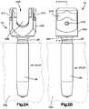
- FIG. 2Aillustrates a front elevational view of a portion the polyaxial bone fixation element shown in FIG. 1 , mounted in a patient's vertebra;
- FIG. 2Billustrates a side elevational view of the portion of the polyaxial bone fixation element shown in FIG. 1 , mounted in the patient's vertebra;
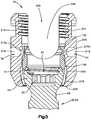
- FIG. 3illustrates a partial, cross-sectional view of the polyaxial bone fixation element shown in FIG. 1 , taken along line 3 - 3 of FIG. 2B ;
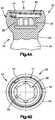
- FIG. 4Aillustrates a magnified cross-sectional view of a head portion of a bone anchor used in connection with the polyaxial bone fixation element shown in FIG. 1 ;
- FIG. 4Billustrates a top plan view of the bone anchor shown in FIG. 4A ;
- FIG. 5Aillustrates a front elevational view of a collet used in connection with the polyaxial bone fixation element shown in FIG. 1 ;
- FIG. 5Billustrates a side elevational view of the collet shown in FIG. 5A ;
- FIG. 5Cillustrates a cross-sectional view of the collet shown in FIG. 5A , taken along line 5 C- 5 C of FIG. 5B ;
- FIG. 6Aillustrates a front elevational view of a first preferred embodiment of a body used in connection with the polyaxial bone fixation element shown in FIG. 1 ;
- FIG. 6Billustrates a side elevational view of the body shown in FIG. 6A ;
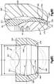
- FIG. 6Cillustrates a cross-sectional view of the body shown in FIG. 6A , taken along line 6 C- 6 C of FIG. 6B ;
- FIG. 6Dillustrates a magnified, cross-sectional view of a lower end of the body shown in FIG. 6A , taken from within circle 6 D of FIG. 6C ;
- FIG. 6Eillustrates a magnified, cross-sectional view of the lower end of the body shown in FIG. 6D and a collet and head of a bone anchor of the polyaxial bone fixation element shown in FIG. 1 ;
- FIG. 6Fillustrates a magnified, cross-sectional view of a second preferred embodiment of a lower end of a body of the polyaxial bone fixation element shown in FIG. 1 ;
- FIG. 6Gillustrates a magnified, cross-sectional view of the lower end of the body shown in FIG. 6F ;
- FIG. 7Aillustrates a top plan view of a locking cap used in connection with the polyaxial bone fixation element shown in FIG. 1 ;
- FIG. 7Billustrates a cross-sectional view of the locking cap shown in FIG. 7A , taken along line 7 B- 7 B of FIG. 7A ;
- FIG. 8Aillustrates a side perspective view of a preferred embodiment of a screw driver and a sleeve coupled to a portion of the polyaxial bone fixation element of FIG. 1 ;
- FIG. 8Billustrates a cross-sectional view of the screw driver and sleeve coupled to the portion of the polyaxial bone fixation element of FIG. 1 , taken along line 8 B- 8 B of FIG. 8A ;
- FIG. 9Aillustrates a cross-sectional view of a syringe assembly and the sleeve coupled to a portion of the polyaxial bone fixation element of FIG. 1 ;
- FIG. 9Billustrates a magnified, cross-sectional view of the syringe assembly and sleeve shown in FIG. 9A , taken from within the circle 9 B of FIG. 9A .
- a preferred polyaxial bone fixation element 10includes a bone anchor 20 (shown as a bone screw), a collet 150 , a body 200 , and a locking cap 300 (shown as an externally threaded set screw).
- the polyaxial bone fixation element 10preferably enables in-situ assembly. That is, preferably, the polyaxial bone fixation element 10 is configured so that in use, the bone anchor 20 may be secured to a patient's vertebra 700 prior to being received within the body 200 .
- the polyaxial bone fixation element 10preferably enables a surgeon to implant the bone anchor 20 without the body 200 and collet 150 pre-assembled to the bone anchor 20 .
- the polyaxial bone fixation element 10maximizes visibility and access around the anchoring site.
- the body 200 and collet 150may “pop-on” to the bone anchor 20 .
- the preferred polyaxial bone fixation element 10is typically considered a bottom loading device, because the bone anchor 20 enters the body 200 through a lower or bottom end 204 .
- the polyaxial bone fixation element 10may be provided pre-assembled using identical components as described herein or may be configured for top loading with minor modifications, as would be apparent to one having ordinary skill in the art.
- collet 150 and body 200 assemblymay be popped-off of the bone anchor 20 in-situ by arranging the collet 150 relative to the body 200 in a loading position, after the fixation element 10 has been arranged in the locked position, and removing the assembly from the bone anchor 20 , as will be described in greater detail below.
- polyaxial bone fixation element 10will be described as and may generally be used in the spine (for example, in the lumbar, thoracic or cervical regions), those skilled in the art will appreciate that the polyaxial bone fixation element 10 may be used for fixation of other parts of the body such as, for example, joints, long bones or bones in the hand, face, feet, extremities, cranium, etc.
- spinal rod 250may include, but is not limited to, a solid rod, a non-solid rod, a flexible or dynamic rod, etc.
- polyaxial bone fixation element 10is not limited in use to any particular type of spinal rod 250 .
- the bone anchor 20preferably is in the form of a bone screw 22 .
- the bone anchor 20may be, for example, a hook or other fastener such as, a clamp, an implant, etc.
- the bone screw 22preferably includes an enlarged, curvate head portion 24 and an externally threaded shaft portion 26 for engaging the patient's vertebra 700 .
- the specific features of the shaft 26including, for example, thread pitch, shaft diameter, shaft shape, etc. are interchangeable, and it would be apparent to one having ordinary skill in the art that the bone screw 22 is not limited to any particular type of shaft 26 .
- the bone screw 22may or may not be cannulated (See FIGS. 9A and 9B ).
- the bone screw 22may also include a reduced diameter neck portion 28 between the head portion 24 and the shaft portion 26 , which accommodates the polyaxial nature of the bone fixation element 10 .
- the bone screw 22may further be cannulated and fenestrated (not shown) such that openings extend outwardly from a central hollow channel in a cannulated screw to urge fluid out of the screw during injection or draw fluid into the central hollow channel from sides of the screw during extraction of material adjacent the screw.
- the enlarged curvate head portion 24preferably has a curvate or semi-spherical shape to facilitate rotation with respect to the collet 150 , as will be described in greater detail below.
- the head portion 24also preferably includes a drive surface 30 for receiving a corresponding tip 501 formed on a drive tool, such as a screw driver 500 ( FIGS. 8A and 8B ) for rotating the bone screw 22 into engagement with the patient's vertebra 700 .
- the drive surface 30may have any form now or hereafter known including, but not limited to, an external hexagon, a star drive pattern, a Phillips head pattern, a slot for a screw driver, a threading for a correspondingly threaded post, etc.
- the drive surface 30is comprised of a first tool interface or an internal recess 32 , but is not so limited and may be comprised of an external drive feature that engages a female-type driver (not shown).
- the specific shape of the drive surface 30 or first tool interface 32may be chosen to cooperate with the corresponding drive tool.
- the head portion 24may also include a second tool interface or a sleeve interface 40 .
- the second tool interface 40may be in any form now or hereafter known including, but not limited to, an internal or external thread, an external hexagon, a star drive pattern, a Phillips head pattern, a slot for a screw driver, a groove, a slot, etc.
- the second tool interface 40includes a plurality of threads 42 for threadably engaging a surgical instrument, such as a sleeve 600 ( FIGS. 8A-9B ), bone augmentation instrumentation, aspiration instrumentation, reduction tool for sagittal reduction or other reduction, coronal rotation tool, soft tissue refraction tool, kyphosis and lordosis correction tool, etc.
- the second tool interface 40 of the preferred embodimentpermits application of forces to the bone anchor 20 along a longitudinal axis of the bone anchor 20 , as well as along or at angles to the axis.
- the sleeve 600is adaptable for use in combination with at least the screw driver 500 and an injection assembly 650 .
- the surgical instrumentmay alternatively be any surgical instrument now or hereafter used in connection with a spinal fixation procedure including, but not limited to, a compressor, a distractor, minimally invasive instrumentation, etc.
- the sleeve 600is able to directly engage the bone anchor 20 thus eliminating the need for the sleeve 600 to engage the body 200 of the polyaxial bone fixation element 10 and thereby, limiting toggling between the sleeve 600 , screw driver 500 and/or bone anchor 20 in a working configuration, as will be described in greater detail below.
- the preferred second tool interface 40permits application of forces to the bone anchor 20 through the sleeve 600 or another tool that mates with the second tool interface 40 to manipulate the bone anchor 20 and potentially the bone that the bone anchor 20 is mounted in.
- the second tool interface 40 and the first tool interface 32are preferably formed in a head interface cavity 41 exposed from the top end of the head 24 . Exposing both the second tool interface 40 and the first tool interface 32 at the top end of the head 24 permits simultaneous engagement of instruments with the second tool interface 40 and first tool interface 32 for manipulating the bone anchor 20 . Both the second tool interface 40 and the first tool interface 32 may be engaged individually or simultaneously by an instrument prior to mounting the collet 150 and body 200 to the head 24 or after the collet 150 and body 200 are mounted to the head 24 (See FIGS. 8B and 9B ).
- the collet 150preferably includes a first or upper end 152 sized and configured to contact at least a portion of the spinal rod 250 (schematically depicted in FIG. 5A ) when the spinal rod 250 is received within a rod-receiving channel 208 formed in the body 200 and a second or lower end 154 sized and configured to contact at least a portion of the head portion 24 of the bone anchor 20 .
- the upper end 152 of the collet 150includes a seat 160 sized and configured to receive at least a portion of the spinal rod 250 when the spinal rod 250 is received within the rod-receiving channel 208 of the body 200 .
- the lower end 154 of the collet 150preferably includes an interior cavity 165 for receiving and securing the head portion 24 of the bone anchor 20 so that, as will be generally appreciated by one of ordinary skill in the art, the bone anchor 20 can polyaxially rotate through a range of angles with respect to the collet 150 and hence with respect to the body 200 .
- the cavity 165 formed in the collet 150preferably has a curvate or semi-spherical shape for receiving the curvate or semi-spherical head portion 24 of the bone anchor 20 so that the bone anchor 20 can polyaxially rotate with respect to the collet 150 and hence with respect to the body 200 .
- the outer surface of the collet 150is comprised of a curvate or spherical, convex surface 151 having a radius of curvature r.sub.5 for contacting the inner surface 211 of the body 200 , preferably the lower edge portion 218 , as will be described in greater detail below.
- the collet 150preferably also includes one or more slots 170 (shown as a plurality of slots) extending from the lower end 154 thereof so that at least a portion of the collet 150 is: (i) radially expandable so that the head portion 24 of the bone anchor 20 can be inserted through the lower end 154 and into the cavity 165 of the collet 150 and (ii) radially compressible to compress or crush-lock against the head portion 24 of the bone anchor 20 , in accordance with the application of radial forces applied thereto.
- the slots 170define a plurality of flexible arms 172 .
- each flexible arm 172includes a root end 173 and a terminal end 174 .
- the outer surface of the flexible arms 172preferably include the curvate or spherical convex surface 151 of the collet 150 for defining a line-contact with the inner surface 211 of the body 200 , preferably the first undercut 218 a , as will be described in greater detail below.
- the collet 150may also include one or more grooves 175 formed on the outer surface thereof for engaging a projection or dimple 216 a formed in the inner surface 211 of the body 200 .
- the collet 150is permitted to float within the axial bore 206 formed in the body 200 between a loading position and a locked position. That is, the collet 150 is preferably movably positioned within the body 200 in an assembled configuration. Interaction between the one or more grooves 175 and the projection or dimples 216 a prevents the collet 150 from moving out of the upper end 202 of the body 200 when in the loading position.
- the collet 150also includes a bore 156 extending from the upper end 152 to the lower end 154 with an upper opening at the upper end 152 so that, for example, a drive tool, such as, for example, a screw driver 500 , can be inserted through the collet 150 and into engagement with the bone anchor 20 so that the bone anchor 20 may be rotated into engagement with the patient's vertebra 700 .
- the upper opening at the upper end 152 of the collet 150also permits simultaneous insertion of the screw driver 500 and a second tool, such as the sleeve 600 , therethrough to engage the head 24 ( FIGS. 8B and 9B ).
- the collet 150may also include one or more provisional rod-locking features so that the spinal rod 250 may be provisionally coupled to the collet 150 , and hence with respect to the body 200 .
- the provisional rod-locking featuresmay be any mechanism now or hereafter developed for such purpose.
- the collet 150includes one or more inwardly projecting ledges 184 , 186 disposed on an inner surface 161 of the seat 160 adjacent the upper end 152 of the collet 150 .
- the ledges 184 , 186may be engaged by a tool (not shown) to apply a force between the collet 150 and the body 200 to move the collet 150 relative to the body 200 .
- the body 200may be urged downwardly toward the bone anchor 20 relative to the collet 150 when the collet 150 , body 200 and bone anchor 20 are in the locked position.
- Such application of a forcemay move the collet 150 from the locked position into the loading position, in situ, such that the flexible arms 172 are able to flex outwardly within an enlarged diameter portion 220 to permit the head 24 to move out of the cavity 165 .
- the ledges 184 , 186may be utilized to disassemble the collet 150 and body 200 from the bone anchor 20 after the collet 150 and body 200 have been locked to the head 24 .
- the body 200may generally be described as a cylindrical tubular body having a longitudinal axis 201 , an upper end 202 having an upper opening 203 , a lower end 204 having a lower opening 205 , and an axial bore 206 substantially coaxial with the longitudinal axis 201 of the body 200 .
- the axial bore 206extends from the upper opening 203 to the lower opening 205 .
- the axial bore 206preferably has a first diameter portion D 1 proximate the upper end 202 .
- the body 200also includes a substantially transverse rod-receiving channel 208 (shown as a top loading U-shaped rod-receiving channel) defining a pair of spaced apart arms 209 , 210 .
- the inner surface 211 of the spaced apart arms 209 , 210preferably includes a plurality of threads 212 for engaging a locking cap 300 .
- the body 200 and, in particular, the spaced apart arms 209 , 210may have nearly any mounting receiving structure for engaging the locking cap 300 including, but not limited to, external threads, cam-lock, quarter lock, clamps, etc.
- the outer surface 213 of the spaced apart arms 209 , 210may each include a recess 214 for engaging one or more surgical instruments such as, for example, rocker forceps, a compressor, a distractor, a sleeve, minimally invasive instrumentation, etc.
- surgical instrumentssuch as, for example, rocker forceps, a compressor, a distractor, a sleeve, minimally invasive instrumentation, etc.
- the axial bore 206preferably has the first diameter portion D 1 proximate the upper end 202 .
- the inner surface 211 of the axial bore 206preferably also includes a lower end portion 218 proximate the lower end 204 thereof.
- the lower end portion 218defines a second diameter portion D 2 , which is comprised of the smallest diameter portion of the axial bore 206 .
- the second diameter portion D 2is preferably defined by a first spherical undercut 218 a adjacent the lower end 204 of the body 200 .
- the first spherical undercut 218 apreferably has a second radius of curvature r2 that is centered on the longitudinal axis 201 of the body 200 .
- the second diameter portion D 2is preferably smaller than the first diameter portion D 1 of the axial bore 206 such that the collet 150 may be inserted through the upper end 202 into the axial bore 206 , but generally preventing the collet 150 from being inserted into the lower end 204 or from falling out of the lower end 204 once inserted into the axial bore 206 .
- the first spherical undercut 218 ais preferably defined as a curvate or spherical concave surface for accommodating the outer curvate or spherical convex surface 151 of the collar 150 .
- the first spherical undercut 218 a and the spherical convex surface 151preferably have a different radius of curvature such that line contact is defined between the surfaces 151 , 218 when the collet 150 is positioned proximate the lower end 204 .
- the second diameter portion D 2is preferably sized and configured so that the enlarged head portion 24 of the bone anchor 20 may be passed through the lower opening 205 of the body 200 , but is prevented from passing therethrough once the head portion 24 of the bone anchor 20 is received within the interior cavity 165 of the collar 150 .
- the inner surface 211 of the axial bore 206preferably includes an enlarged portion 220 that is located toward the lower end 204 relative to the first diameter portion D 1 .
- the enlarged portion 220preferably defines a third diameter D 3 comprised of a curvate, preferably spherical, radially outwardly recessed portion.
- the third diameter D 3is larger than the first diameter D 1 of the axial bore 206 .
- the third diameter D 3is larger than the second diameter D 2 .
- the third diameter D 3is defined by a second spherical undercut 220 a.
- the enlarged portion 220is preferably located in between the upper end 202 and the lower end portion 218 and accommodates expansion of the flexible arm 172 therein when the head 24 is loaded into the collet 150 , as will be described in greater detail below.
- the enlarged portion 220is preferably in the form of a curvate or spherical concave surface having a third radius of curvature r3, which defines the third diameter D 3 at the largest diameter within the axial bore 206 .
- the third radius of curvature r3defines the spherical nature of the second spherical undercut 220 a .
- the enlarged portion 220is sized and configured so that when the collet 150 is placed in general alignment with the curvate or spherical concave surface of the enlarged portion 220 , the flexible arms 172 of the collet 160 are permitted to radially expand within the axial bore 206 of the body 200 so that the head portion 24 of the bone anchor 20 can be inserted through the lower opening 205 formed in the body 200 and into the cavity 165 formed in the collet 150 . More preferably, the enlarged portion 220 is sized and configured so that the outer curvate or spherical convex surface 151 of the collet 150 does not touch or contact the enlarged portion 220 of the body 200 when the head 24 is loaded into the collet 150 .
- the enlarged portion 220 formed in the body 200is preferably sized and configured so that a gap remains between the outer curvate or spherical convex surface 151 of the collet 150 and the enlarged portion 220 of the body 200 even when the flexible arms 172 radially expand to accept the head portion 24 of the bone anchor 20 .
- the enlarged portion 220is not limited to constructions comprised of the preferred curvate or spherical undercut defined by the third radius of curvature r3 and may be constructed of nearly any undercut having nearly any shape that permits expansion of the collet 150 therein in the loading position to accept the head 24 .
- the enlarged portion 220may be defined by a rectangular slot or groove on the inner surface 211 that results in the third diameter D 3 being larger than the first and second diameters D 1 , D 2 .
- the second radius of curvature r2 of the first spherical undercut 218 ais preferably different than an outer radius of curvature r5 of the outer curvate or spherical convex surface 151 of the collet 150 so a line contact results between the first spherical undercut 218 a and the outer convex surface 151 when the collet 150 is positioned adjacent the lower end portion 218 .
- the line contact between the collet 150 and body 200permits disengagement of the collet 150 from the body 200 after the collet 150 and body 200 are engaged in the locked position or popping-off of the body 200 and collet 150 from the bone anchor 20 , in situ.
- the second and third diameters D 2 , D 3may be formed by a single internal radius of curvature r4 that undercuts the body 200 in the axial bore 206 .
- the single internal radius of curvature r4preferably permits expansion of the collet 150 to accept the head 24 , insertion of the collet 150 into the axial bore 206 from the upper end 202 but not the lower end 204 and line contact between the outer curvate or spherical convex surface 151 of the collet and the lower end portion 218 when the collet 150 is in facing engagement with the lower end portion 218 .
- the second diameter portion D 2is smaller than the first diameter portion D 1 , which is smaller than the third diameter portion D 3 .
- the body 200 and collet 150also preferably include a collet retention feature 50 so that once the collet 150 has been inserted into the bore 206 formed in the body 200 and, if necessary, the collet retention feature 50 has been engaged, the collet retention feature 50 inhibits the collet 150 from passing back through the upper opening 203 formed in the body 200 , but permits some degree of vertical translation or floating of the collet 150 with respect to the body 200 . That is, once inserted into the axial bore 206 of the body 200 , the collet 150 is sized and configured to float or move within the axial bore 206 between a loading position and a locking position.
- the collet retention feature 50preferably prevents the collet 150 from moving out of the upper opening 203 of the body 200 .
- the collet retention feature 50permits the flexible arms 172 to align with the enlarged portion 220 in the loading position when the lower edge of the grooves 175 come into contact with the dimples 216 a .
- the collet 150is preferably permitted to float between the loading position and the locking position prior to locking of the head 24 in the collet 150 .
- the collet 150may float between the loading position where the dimples 216 a are in contact with the lower edge of the grooves 175 and the locking position wherein the outer curvate or spherical convex surface 151 is in line contact with the lower end portion 218 .
- the collet retention feature 50preferably limits rotation of the collet 150 with respect to the body 200 , because the dimples 216 a slide within the grooves 175 , so that the seat 160 formed in the collet 150 is aligned with the rod-receiving channel 208 formed in the body 200 .
- the retention feature 50is not limited to limiting rotation of the collet 150 with respect to the body 200 and may be configured to permit unlimited rotation of the collet 150 relative to the body 200 by eliminating the grooves 175 from the collet 150 and forming a shelf (not shown) around the collet 150 at the bottom end of the grooves 175 such that the dimples 216 a engage the shelf to limit removal of the collet 150 out of the upper end 202 of the body 200 , but permit unlimited rotation of the collet 150 relative to the body 200 in the assembled configuration.
- the collet retention feature 50may be any feature now or hereafter known for such purpose including, but not limited to, for example, an inwardly protruding shoulder or detent formed on the collet 150 for engaging corresponding indentations formed on the inner surface 211 of the body 200 .
- the body 200includes one or more partial passageways 216 formed therein so that once the collet 150 has been received within the axial bore 206 of the body 200 , a force may be applied to the partial passageways 216 formed in the body 200 deforming the remaining portion of the partial passageway 217 into the dimple or projection 216 a formed in the inner surface 211 of the body 200 .
- an external forcemay be applied to the partial passageways 216 formed in the body 200 transforming the passageways 216 into the projections or dimples 216 a that extend inwardly from the inner surface 211 of the spaced apart arms 209 , 210 and into the bore 206 formed in the body 200 .
- the dimples or projections 216 aare preferably sized and configured to interact with the longitudinal groove 175 formed in the outer surface of the collet 150 so that the collet 150 is permitted to move with respect to the body 200 at least along the longitudinal axis 201 , but inhibited from moving back through the upper opening 203 formed in the body 200 .
- the collet 150is also preferably partially inhibited from rotational movement with respect to the body 200 . Movement of the collet 150 with respect to the body 200 toward the upper end 202 is preferably inhibited by the projections or dimples 216 a contacting the bottom and/or lateral surfaces of the grooves 175 . Limiting rotational movement of the collet 150 with respect to the body 200 permits alignment of the rod-receiving channel 208 and the seat 160 for receiving the rod 250 , as will be described in greater detail below.
- positioning the collet 150 in general alignment with the curvate or spherical concave surface of the enlarged portion 220 in the loading positionpreferably enables the flexible arms 172 of the collet 150 to radially expand within the axial bore 206 of the body 200 so that the head portion 24 of the bone anchor 20 can be inserted through the lower opening 205 formed in the body 200 and into the cavity 165 formed in the collet 150 .
- the enlarged portion 220 formed in the body 200is preferably sized and configured so that a gap remains between the outer curvate or spherical convex surface 151 of the collet 150 and the enlarged portion 220 of the body 200 even when the flexible arms 172 radially expand to accept the head portion 24 of the bone anchor 20 .
- movement of the collet 150 into general alignment and engagement with the first spherical undercut 218 a of the lower end portion 218causes a radial inward force to be applied to the flexible arms 172 , which in turn causes the flexible arms 172 to compress against the head portion 24 of the bone anchor 20 , thereby securing the position of the bone anchor 20 with respect to the collet 150 and hence with respect to the body 200 .
- the lower end portion 218 and the outer curvate or spherical convex surface 151 of the collet 150have non-matching radii of curvature r2, r4, r5 so that only line contact occurs between these components.
- the head portion 24 of the bone anchor 20 and interaction of the dimples 216 with the grooves 175preferably moves the collet 150 into alignment with the enlarged portion 220 as the head portion 24 is inserted through the lower opening 205 and into the axial bore 206 . Moreover, the collet 150 is preferably moved into alignment and engagement with the lower edge portion 218 via engagement of the locking cap 300 , as will be described in greater detail below.
- the locking cap 300is preferably an externally threaded set screw 302 for threadably engaging the threads 212 formed on the inner surface 211 of the body 200 .
- the externally threaded set screw 302generally provides flexibility when inserting a spinal rod 250 into the body 200 such that the spinal rod 250 does not have to be completely reduced or seated within the body 200 prior to engagement of the cap 300 . Incorporation of a threaded set screw 302 also enables the set screw 302 to reduce the spinal rod 250 during tightening of the locking cap with respect to the body 200 .
- the locking cap 300may be any locking cap now or hereafter developed for such purpose including, but not limited to, an externally threaded cap, a quarter-turn or partial-turn locking cap, two-piece set screw, etc.
- the externally threaded set screw 302preferably includes a drive surface 304 for engaging a corresponding drive tool for securing (e.g., threading) the set screw 302 onto the body 200 .
- the drive surface 304may take on any form now or hereafter developed for such purpose, including, but not limited to, an external hexagon, a star drive pattern, a Phillips head pattern, a slot for a screw driver, a threading for a correspondingly threaded post, etc.
- the drive surface 304is preferably comprised of an internal recess. The specific shape of the internal recess may be chosen to cooperate with the corresponding drive tool.
- the drive surface 304may also be configured to include the first and second tool interfaces 40 , as were described above.
- the externally threaded set screw 302preferably also includes a saddle 310 operatively coupled thereto.
- the saddle 310includes a transverse recess 312 formed therein for contacting at least a portion of the spinal rod 250 .
- the rod-contacting surface of the recess 312may include a surface finish (not shown) that adds roughness, such as, for example, a knurl, bead blasting, grooves, or other textured finish that increases surface roughness and enhances rod push through strength.
- the saddle 310may be coupled to the set screw 302 by any means now or hereafter developed for such purpose including, but not limited to, adhesion, mechanically fastening, etc.
- the set screw 302preferably includes a bore 306 for receiving a stem 316 formed on a top surface 311 of the saddle 310 .
- the saddle 310is preferably coupled to the set screw 302 but is free to rotate with respect to the set screw 302 so that the saddle 310 can self-align with the spinal rod 250 while the set screw 302 is being rotated with respect to the body 200 .
- the threads formed on the externally threaded set screw 302may incorporate inclined load flanks forming an angle with respect to the longitudinal axis 201 of the body 200 .
- the load flanksmay be converging so that the top surface of the thread and the bottom surface of the thread converge.
- the anglemay be about five degrees (5.degree.), although, as will be generally appreciated by one of ordinary skill in the art, the threads may take on any other form now or hereafter known for such purpose including, negative load threads, perpendicular threads flanks, buttress threads, etc.
- the polyaxial bone fixation element 10is preferably provided to the user in a kit including at least (1) bone anchors, (2) locking caps, and (3) pre-assembled collet/body subassemblies.
- the pre-assembled collet/body subassembliesare preferably assembled by inserting the collet 150 into the axial bore 206 formed in the body 200 through the upper opening 203 formed in the body 200 .
- the flexible arms 172may flex inwardly as the collet 150 is inserted into the axial bore 206 , if the greatest diameter of the flexible arms 172 is larger than the first diameter D 1 .
- Such a configurationgenerally results in the collet 150 being retained within the axial bore 206 , even before the collet retention feature 50 is engaged.
- the projection or dimple 216 ais positioned within the longitudinal groove 175 formed in the collet 150 so that the collet 150 is free to vertically translate or float within the bore 206 with respect to the body 200 , but generally prevented from passing back up through the upper opening 203 formed in the body 200 and limited in its ability to rotate relative to the body 200 .
- the kitis preferably shipped to the user for use in spinal surgery.
- the surgeonpreferably identifies a level of the spine where the surgery will take place, makes and incision to expose the selected area and implants the bone anchors 20 into the desired vertebrae 700 .
- the body/collet subassembliesare preferably popped-on to the bone anchors 20 by urging the head 24 through the lower opening 205 . Accordingly, the collet/body subassembly may be engaged with the head portion 24 of the bone anchor 20 in situ. Specifically, as the head 24 moves into the lower opening 205 , the collet 150 is urged toward and into the loading position wherein the lower end of the longitudinal grooves 175 contact the dimples 216 a .
- the outer curvate or spherical convex surface 151 of the collet 150is in general vertical alignment with the enlarged curvate or spherical concave surface of the enlarged portion 220 formed in the axial bore 206 of the body 200 . Alignment of the enlarged portion 220 with the collet 150 enables the collet 150 to radially or outwardly expand so that the head portion 24 of the bone anchor 20 can be received within the cavity 165 formed in the collet 150 .
- the head portion 24 of the bone anchor 20 and the collet 150are both preferably constrained within the body 200 .
- the bone anchor 20is preferably able to polyaxially rotate with respect to the collet 150 and the body 200 in this configuration.
- the spinal rod 250is inserted into the rod-receiving channel 208 formed in the body 200 and onto the inner surface 161 of the seat 160 .
- the spinal rod 250is preferably positioned in facing engagement with the inner surface 161 of the seat 160 .
- the set screw 302is preferably threaded into engagement with the threads 212 formed in the body 200 to urge the spinal rod 250 and collet 150 toward the lower end 204 .
- Rotation of the set screw 302causes the bottom surface of the set screw 300 , preferably the saddle 310 , to contact the top surface of the spinal rod 250 , which in turn causes the spinal rod 250 and the collet 150 to move downwards with respect to the body 200 .
- Downward movement of the collet 150 with respect to the body 200causes line contact between the outer curvate or spherical convex surface 151 of the collet 150 and the first spherical undercut 218 a of the lower end portion 218 .
- the line contact between the collet 150 and body 200 proximate the terminal ends 174direct the radial inward force on the flexible arms 172 at a location preferably below the largest diameter of the head 24 to efficiently urge the terminal ends 174 beneath the curved outer surface of the head 24 in the locked position.
- the spinal rod 250is sandwiched between the set screw 302 and the collet 150 in the locking position, thereby securing the position of the spinal rod 250 with respect to the body 200 and the bone anchor 20 .
- the collet 150 and body 200may be popped-off of the bone anchor 20 , in situ, after the bone fixation element 10 is engaged in the locked configuration.
- the set screw 300may be removed from the body 200 and the spinal rod 250 may be extracted from the rod-receiving channel 208 and the seat 160 .
- a tool(not shown) engages the ledges 184 , 186 and the body 200 and applies a force between the collet 150 and the body 200 to move the body 200 downwardly toward the body anchor 20 .
- the line contact between the body 200 and the collet 150is released and the collet 150 is urged into the loading position.
- the flexible arms 172flex outwardly within the enlarged portion 220 to permit popping-off of the body 200 and collet 150 from the head 24 of the bone anchor 20 .
- the collet 150 and body 200may then be popped back onto the bone anchor 20 .
- the head portion 24 of the bone anchor 20preferably includes a drive surface 30 in the form of an internal drive recess or a first tool interface 32 and a second tool interface 40 .
- the second tool interface 40preferably includes a plurality of threads 42 for threadably engaging the sleeve 600 .
- the sleeve 600preferably accommodates a variety of surgical instruments now or hereafter known including, but not limited to, the screw driver 500 , a fluid delivery device such as the injection assembly 650 , a compressor, a distractor, minimally invasive instrumentation, etc.
- the surgical instrumentsare able to directly engage the bone anchor 20 , thus eliminating the need for the surgical instruments and/or the sleeve 600 to engage the body 200 or collet 150 of the polyaxial bone fixation element 10 .
- the sleeve 600is engaged with the second tool interface 40 , toggling between the screw driver 500 or another instrument inserted through an internal bore in the sleeve 600 and the bone anchor 20 is limited.
- the sleeve 600is utilized to draw the screw driver 500 into the first tool interface 32 to limit toggling between the screw driver 500 and the bone anchor 20 .
- the second tool interface 40is described herein as interacting or engaging the sleeve 600 , but is not so limited and may be configured to interact or engage with nearly any tool or instrument that preferably is utilized to positively engage the head 24 and apply forces to the bone anchor 20 for manipulating the bone anchor 20 , vertebra 700 mounted to the bone anchor 20 or any other structure that is mounted to the bone anchor 20 .
- the sleeve 600includes a threaded distal portion 602 for threadably engaging the threads 42 of the second tool interface 40 . In this manner, the sleeve 600 is directly coupled and secured to the bone anchor 20 .
- the direct connection of the sleeve 600 with the bone anchor 20facilitates protection of the polyaxial locking mechanism (the collet 150 and the body 200 ) of the polyaxial bone fixation element 10 and provides a more stable distraction, because the forces applied to the sleeve 600 are transferred directly to the bone anchor 20 via the second tool interface 40 and into the vertebra 700 , as opposed to acting through these elements as well as the collet 150 and/or the body 200 , which may distort some of the forces and cause toggling.
- instrumentssuch as the screw driver 500 or the injection assembly 650 may be securely positioned in engagement with the bone anchor 20 to drive the bone anchor 20 with the screw driver 500 , inject bone cement or other fluid into and through the bone anchor 20 or otherwise conduct a procedure with the bone anchor 2 , without operating through the body 200 and/or collet 150 .
- the second tool interface 40preferably does not obstruct access to the drive recess 32 , because the second tool interface 40 is preferably located above and radially outwardly relative to the drive recess 32 .
- the second tool interface 40is not limited to being located above and radially outwardly relative to the drive recess or first tool interface 32 and may be located below and radially inwardly relative to the first tool interface 32 , as long as tools or instruments are able to engage the first and second tool interfaces 32 , 40 simultaneously.
- the second tool interface 40may be comprised of a threaded recess in the bone anchor 20 having a smaller diameter and located below the first tool interface 32 .
- the sleeve 600preferably includes the longitudinal bore so that the screw driver 500 , for example, may engage the drive recess 32 formed in the head portion 24 of the bone anchor 20 . In this manner, the sleeve 600 engages the bone anchor 20 via the second tool interface 40 while the screw driver 500 simultaneously engages the drive recess 32 .
- the sleeve 600is preferably associated with a slip sleeve 800 that surrounds the sleeve 600 in a working configuration.
- the sleeve 600 and the screw driver 500are rotatable relative to the slip sleeve 800 such that a surgeon may grasp the slip sleeve 800 while turning a handle 502 on a distal end of the screw driver 500 to screw the bone anchor 20 into or out of the vertebra 700 .
- the surgeonrotates the handle 502 , the sleeve 600 , screw driver 500 and bone anchor 20 each rotate relative to the slip sleeve 800 .
- the injection assembly 650may be utilized with the sleeve 600 to inject bone cement or other flowable materials into a cannulated bone anchor 20 ′.
- a cannula 652 of the injection assembly 650is inserted into the sleeve 600 .
- the cannula 652is associated with a syringe 654 at a proximal end and includes a blunt tip 656 at a distal end.
- the cannula 652preferably includes an engagement mechanism 656 proximate the proximal end to engage a proximal end of the sleeve 600 to secure the cannula 652 to the sleeve 600 .
- the engagement mechanism 656preferably urges the blunt tip 656 of the cannula 652 into engagement with a shelf 32 a at the bottom of the first tool interface 32 such that a flow channel 34 of the cannula 652 is in communication with a flow channel 652 a of the cannula and a seal is created between the blunt tip 656 and the shelf 32 a .
- the engagement mechanism 656is comprised of a threaded joint that may be tightened to secure the cannula 652 relative to the sleeve 600 and securely seal the blunt tip 656 to the shelf 32 a , thereby generally preventing leakage of bone cement or other flowable fluid into the first tool interface 32 .
- Bone cementis preferably injected into the flow channel 652 a with the injection assembly 650 and into the vertebra 700 to securely mount the bone anchor 20 ′ to the vertebra 700 , particularly in generally weak, brittle and/or osteoporotic bone.
- the bone anchor 20 ′may also be fenestrated to inject bone cement toward the sides of the bone anchor 20 ′ or to generally directionally dispense the bone cement or other fluid.
- the bone anchor 20 ′may be utilized to extract material from the vertebra 700 or other bone that the bone anchor 20 ′ is engaged with by drawing the material into the flow channel 652 a , by, for example, creating a vacuum in the flow channel 652 a .
- the bone anchor 20 ′may be utilized to extract bone marrow from the bone.
- the bone anchor 20 ′may be utilized to aid in bone graft extension, as would be apparent to one having ordinary skill in the art.
- the bone anchor 20is being described herein as preferably including the second tool interface 40 , the second tool interface 40 is optional. Furthermore, it should be understood that the bone anchor 20 including the second tool interface 40 may be used in any other type of bone screw application such as, for example, long bone fixation, fracture fixation, or in connection with securing a bone plate, vertebral spacer, dental implant, etc.
- the polyaxial bone fixation element 10 including the bone anchor 20 , the collet 150 , the body 200 and the locking cap 300may be made from any biocompatible material now or hereafter known including, but not limited to, metals such as, for example, titanium, titanium alloys, stainless steel, Nitinol, etc.
- any or all of the components described hereinmay be provided in sets or kits so that the surgeon may select various combinations of components to perform a fixation procedure and create a fixation system which is configured specifically for the particular needs/anatomy of a patient. It should be noted that one or more of each component may be provided in a kit or set. In some kits or sets, the same device may be provided in different shapes and/or sizes.
Landscapes
- Health & Medical Sciences (AREA)
- Orthopedic Medicine & Surgery (AREA)
- Neurology (AREA)
- Life Sciences & Earth Sciences (AREA)
- Surgery (AREA)
- Heart & Thoracic Surgery (AREA)
- Engineering & Computer Science (AREA)
- Biomedical Technology (AREA)
- Nuclear Medicine, Radiotherapy & Molecular Imaging (AREA)
- Medical Informatics (AREA)
- Molecular Biology (AREA)
- Animal Behavior & Ethology (AREA)
- General Health & Medical Sciences (AREA)
- Public Health (AREA)
- Veterinary Medicine (AREA)
- Surgical Instruments (AREA)
Abstract
Description
Claims (20)
Priority Applications (5)
| Application Number | Priority Date | Filing Date | Title |
|---|---|---|---|
| US16/172,995US10898234B2 (en) | 2007-07-20 | 2018-10-29 | Polyaxial bone fixation element |
| US17/124,625US11819247B2 (en) | 2007-07-20 | 2020-12-17 | Polyaxial bone fixation element |
| US17/328,230US11357550B2 (en) | 2007-07-20 | 2021-05-24 | Polyaxial bone fixation element |
| US17/663,714US11998246B2 (en) | 2007-07-20 | 2022-05-17 | Polyaxial bone fixation element |
| US18/660,365US20240285314A1 (en) | 2007-07-20 | 2024-05-10 | Polyaxial bone fixation element |
Applications Claiming Priority (7)
| Application Number | Priority Date | Filing Date | Title |
|---|---|---|---|
| US95099507P | 2007-07-20 | 2007-07-20 | |
| US98858407P | 2007-11-16 | 2007-11-16 | |
| PCT/US2008/070670WO2009015100A2 (en) | 2007-07-20 | 2008-07-21 | Polyaxial bone fixation element |
| US66922410A | 2010-01-15 | 2010-01-15 | |
| US14/163,482US9439681B2 (en) | 2007-07-20 | 2014-01-24 | Polyaxial bone fixation element |
| US15/254,382US10136923B2 (en) | 2007-07-20 | 2016-09-01 | Polyaxial bone fixation element |
| US16/172,995US10898234B2 (en) | 2007-07-20 | 2018-10-29 | Polyaxial bone fixation element |
Related Parent Applications (1)
| Application Number | Title | Priority Date | Filing Date |
|---|---|---|---|
| US15/254,382ContinuationUS10136923B2 (en) | 2007-07-20 | 2016-09-01 | Polyaxial bone fixation element |
Related Child Applications (1)
| Application Number | Title | Priority Date | Filing Date |
|---|---|---|---|
| US17/124,625ContinuationUS11819247B2 (en) | 2007-07-20 | 2020-12-17 | Polyaxial bone fixation element |
Publications (2)
| Publication Number | Publication Date |
|---|---|
| US20190059953A1 US20190059953A1 (en) | 2019-02-28 |
| US10898234B2true US10898234B2 (en) | 2021-01-26 |
Family
ID=56896274
Family Applications (7)
| Application Number | Title | Priority Date | Filing Date |
|---|---|---|---|
| US14/163,482ActiveUS9439681B2 (en) | 2007-07-20 | 2014-01-24 | Polyaxial bone fixation element |
| US15/254,382ActiveUS10136923B2 (en) | 2007-07-20 | 2016-09-01 | Polyaxial bone fixation element |
| US16/172,995ActiveUS10898234B2 (en) | 2007-07-20 | 2018-10-29 | Polyaxial bone fixation element |
| US17/124,625Active2028-12-04US11819247B2 (en) | 2007-07-20 | 2020-12-17 | Polyaxial bone fixation element |
| US17/328,230ActiveUS11357550B2 (en) | 2007-07-20 | 2021-05-24 | Polyaxial bone fixation element |
| US17/663,714ActiveUS11998246B2 (en) | 2007-07-20 | 2022-05-17 | Polyaxial bone fixation element |
| US18/660,365PendingUS20240285314A1 (en) | 2007-07-20 | 2024-05-10 | Polyaxial bone fixation element |
Family Applications Before (2)
| Application Number | Title | Priority Date | Filing Date |
|---|---|---|---|
| US14/163,482ActiveUS9439681B2 (en) | 2007-07-20 | 2014-01-24 | Polyaxial bone fixation element |
| US15/254,382ActiveUS10136923B2 (en) | 2007-07-20 | 2016-09-01 | Polyaxial bone fixation element |
Family Applications After (4)
| Application Number | Title | Priority Date | Filing Date |
|---|---|---|---|
| US17/124,625Active2028-12-04US11819247B2 (en) | 2007-07-20 | 2020-12-17 | Polyaxial bone fixation element |
| US17/328,230ActiveUS11357550B2 (en) | 2007-07-20 | 2021-05-24 | Polyaxial bone fixation element |
| US17/663,714ActiveUS11998246B2 (en) | 2007-07-20 | 2022-05-17 | Polyaxial bone fixation element |
| US18/660,365PendingUS20240285314A1 (en) | 2007-07-20 | 2024-05-10 | Polyaxial bone fixation element |
Country Status (1)
| Country | Link |
|---|---|
| US (7) | US9439681B2 (en) |
Families Citing this family (49)
| Publication number | Priority date | Publication date | Assignee | Title |
|---|---|---|---|---|
| US9980753B2 (en) | 2009-06-15 | 2018-05-29 | Roger P Jackson | pivotal anchor with snap-in-place insert having rotation blocking extensions |
| US8444681B2 (en) | 2009-06-15 | 2013-05-21 | Roger P. Jackson | Polyaxial bone anchor with pop-on shank, friction fit retainer and winged insert |
| US8100946B2 (en) | 2005-11-21 | 2012-01-24 | Synthes Usa, Llc | Polyaxial bone anchors with increased angulation |
| US8979904B2 (en)* | 2007-05-01 | 2015-03-17 | Roger P Jackson | Connecting member with tensioned cord, low profile rigid sleeve and spacer with torsion control |
| US9439681B2 (en) | 2007-07-20 | 2016-09-13 | DePuy Synthes Products, Inc. | Polyaxial bone fixation element |
| AU2010260521C1 (en)* | 2008-08-01 | 2013-08-01 | Roger P. Jackson | Longitudinal connecting member with sleeved tensioned cords |
| JP5815407B2 (en) | 2008-09-12 | 2015-11-17 | ジンテス ゲゼルシャフト ミット ベシュレンクテル ハフツング | Spinal stabilization and guided fixation system |
| KR20110081208A (en) | 2008-09-29 | 2011-07-13 | 신세스 게엠바하 | Multi-Axis Bottom-Loading Screw and Rod Assemblies |
| CA2742399A1 (en) | 2008-11-03 | 2010-06-03 | Dustin M. Harvey | Uni-planar bone fixation assembly |
| KR20120013312A (en) | 2009-04-15 | 2012-02-14 | 신세스 게엠바하 | Orthodontic Connectors for Spinal Structures |
| CN103826560A (en) | 2009-06-15 | 2014-05-28 | 罗杰.P.杰克逊 | Polyaxial Bone Anchor with Socket Stem and Winged Inserts with Friction Fit Compression Collars |
| US11464549B2 (en) | 2009-06-15 | 2022-10-11 | Roger P. Jackson | Pivotal bone anchor assembly with horizontal tool engagement grooves and insert with upright arms having flared outer portions |
| CA2764841A1 (en) | 2009-06-17 | 2010-12-23 | Synthes Usa, Llc | Revision connector for spinal constructs |
| EP2485654B1 (en) | 2009-10-05 | 2021-05-05 | Jackson P. Roger | Polyaxial bone anchor with non-pivotable retainer and pop-on shank, some with friction fit |
| AU2011324058A1 (en)* | 2010-11-02 | 2013-06-20 | Roger P. Jackson | Polyaxial bone anchor with pop-on shank and pivotable retainer |
| JP5865479B2 (en) | 2011-03-24 | 2016-02-17 | ロジャー・ピー・ジャクソン | Multiaxial bone anchor with compound joint and pop-mounted shank |
| EP2606841B1 (en)* | 2011-12-23 | 2016-03-09 | Biedermann Technologies GmbH & Co. KG | Polyaxial bone anchoring device |
| KR101199458B1 (en)* | 2012-02-17 | 2012-11-09 | 고려대학교 산학협력단 | Apparatus for fixation of spine |
| US9259247B2 (en) | 2013-03-14 | 2016-02-16 | Medos International Sarl | Locking compression members for use with bone anchor assemblies and methods |
| DE102013109895A1 (en)* | 2013-09-10 | 2015-03-12 | Aesculap Ag | Medical instrument |
| EP2932929B1 (en)* | 2014-04-15 | 2017-02-08 | Biedermann Technologies GmbH & Co. KG | A screw element for use in spinal, orthopedic or trauma surgery and a system of such a screw element and a screw driver adapted thereto |
| DE102014109200A1 (en) | 2014-07-01 | 2016-01-07 | Aesculap Ag | Medical screwdriver, shaft for the medical screwdriver and method for introducing pedicle screws |
| US10543021B2 (en) | 2014-10-21 | 2020-01-28 | Roger P. Jackson | Pivotal bone anchor assembly having an open ring positioner for a retainer |
| US10368923B2 (en)* | 2014-10-28 | 2019-08-06 | Neurostructures, Inc. | Bone fixation system |
| EP3023064B1 (en) | 2014-11-20 | 2019-01-09 | Biedermann Technologies GmbH & Co. KG | Receiving part for coupling a bone anchor to a rod and bone anchoring device with such a receiving part |
| DE102015008036A1 (en) | 2015-06-09 | 2016-12-15 | Signus Medizintechnik Gmbh | Pedicle screw with tulip |
| US9968378B1 (en)* | 2015-07-22 | 2018-05-15 | University Of South Florida | Adaptation sphere saddle |
| FR3052657B1 (en)* | 2016-06-21 | 2020-12-18 | Innoprod Medical | SPECIFIC INSTRUMENTATION DEDICATED TO THE PERCUTANEOUS PLACEMENT OF AN IMPLANT ALLOWING A TARGETED INJECTION |
| US10568667B2 (en) | 2016-07-13 | 2020-02-25 | Medos International Sàrl | Bone anchor assemblies and related instrumentation |
| US10874438B2 (en) | 2016-07-13 | 2020-12-29 | Medos International Sarl | Bone anchor assemblies and related instrumentation |
| US10463402B2 (en) | 2016-07-13 | 2019-11-05 | Medos International Sàrl | Bone anchor assemblies and related instrumentation |
| US10363073B2 (en) | 2016-07-13 | 2019-07-30 | Medos International Sàrl | Bone anchor assemblies and related instrumentation |
| JP2019531835A (en)* | 2016-10-31 | 2019-11-07 | エピックス オーソペディックス インコーポレイテッド | Sterilization tray for facilitating attachment of implant insertion devices to implantable devices |
| US10980641B2 (en) | 2017-05-04 | 2021-04-20 | Neurostructures, Inc. | Interbody spacer |
| US10512547B2 (en) | 2017-05-04 | 2019-12-24 | Neurostructures, Inc. | Interbody spacer |
| US10610365B2 (en)* | 2017-12-23 | 2020-04-07 | Onkos Surgical, Inc. | Implant with ability to capture extravasating fixation medium |
| US11076892B2 (en) | 2018-08-03 | 2021-08-03 | Neurostructures, Inc. | Anterior cervical plate |
| US11071629B2 (en) | 2018-10-13 | 2021-07-27 | Neurostructures Inc. | Interbody spacer |
| WO2020102787A1 (en) | 2018-11-16 | 2020-05-22 | Surber, James L. | Pivotal bone anchor assembly having a deployable collet insert with internal pressure ring |
| EP3656320B1 (en)* | 2018-11-20 | 2022-08-24 | Biedermann Technologies GmbH & Co. KG | Anchoring member for a polyaxial bone anchoring device and polyaxial bone anchoring device with such an anchoring member |
| US12082848B2 (en) | 2019-02-27 | 2024-09-10 | Orthopediatrics Corp. | Bone anchors with cord retention features |
| US11633219B2 (en)* | 2019-06-26 | 2023-04-25 | Globus Medical, Inc. | Fenestrated pedicle nail |
| US11382761B2 (en) | 2020-04-11 | 2022-07-12 | Neurostructures, Inc. | Expandable interbody spacer |
| US11304817B2 (en) | 2020-06-05 | 2022-04-19 | Neurostructures, Inc. | Expandable interbody spacer |
| US11717419B2 (en) | 2020-12-10 | 2023-08-08 | Neurostructures, Inc. | Expandable interbody spacer |
| US11903620B2 (en) | 2021-01-25 | 2024-02-20 | Medos International Sarl | Flexible sleeve for bone fixation, and related systems and methods |
| WO2022184797A1 (en) | 2021-03-05 | 2022-09-09 | Medos International Sarl | Selectively locking polyaxial screw |
| US12364515B2 (en) | 2021-03-05 | 2025-07-22 | Medos International Sàrl | Multi-feature polyaxial screw |
| GB2605204B (en)* | 2021-03-26 | 2025-07-02 | Airspan Ip Holdco Llc | Wireless radio system for adjusting path loss calculations |
Citations (437)
| Publication number | Priority date | Publication date | Assignee | Title |
|---|---|---|---|---|
| US405546A (en) | 1889-06-18 | Insulator | ||
| US513630A (en) | 1894-01-30 | Detachable electric-wire-holding device | ||
| US527678A (en) | 1894-10-16 | Compression-tank | ||
| US802896A (en) | 1904-11-01 | 1905-10-24 | Nicholas W Webb | Electric lock. |
| US2005348A (en) | 1932-05-23 | 1935-06-18 | Anthony G M Michell | Nut, screw, and like article |
| US2338659A (en) | 1942-10-24 | 1944-01-04 | Adel Prec Products Corp | Conduit clip and supporting bracket |
| US2396925A (en) | 1942-08-01 | 1946-03-19 | Adel Prec Products Corp | Subassembly conduit clip |
| GB820252A (en) | 1957-10-04 | 1959-09-16 | Standard Telephones Cables Ltd | Semiconductor device |
| US3173987A (en) | 1963-03-04 | 1965-03-16 | Lumidor Products Corp | Terminal box with yoke and clip supporting means for cables |
| US3463427A (en) | 1967-08-07 | 1969-08-26 | Illinois Tool Works | Cable strap |
| US4447934A (en) | 1982-06-07 | 1984-05-15 | National Molding Corporation | Cable harness |
| US4601491A (en) | 1983-10-19 | 1986-07-22 | Vetco Offshore, Inc. | Pipe connector |
| US4719905A (en) | 1985-11-01 | 1988-01-19 | Acromed Corporation | Apparatus and method for maintaining vertebrae in a desired relationship |
| US4805602A (en) | 1986-11-03 | 1989-02-21 | Danninger Medical Technology | Transpedicular screw and rod system |
| US4846614A (en) | 1986-12-08 | 1989-07-11 | Rolf Steinbock | Differential thread for transfer of screw thread forces |
| US4863383A (en) | 1987-03-17 | 1989-09-05 | Grafelmann Hans L | self-taping screw-in bone implant for dental purposes |
| US4936851A (en) | 1988-08-26 | 1990-06-26 | Colin Electronics Co., Ltd. | Analytic bone implant |
| US4944475A (en) | 1987-09-04 | 1990-07-31 | Yazaki Corporation | Electric wire bundler |
| US4946458A (en) | 1986-04-25 | 1990-08-07 | Harms Juergen | Pedicle screw |
| US5005562A (en) | 1988-06-24 | 1991-04-09 | Societe De Fabrication De Material Orthopedique | Implant for spinal osteosynthesis device, in particular in traumatology |
| US5116337A (en) | 1991-06-27 | 1992-05-26 | Johnson Lanny L | Fixation screw and method for ligament reconstruction |
| US5129388A (en) | 1989-02-09 | 1992-07-14 | Vignaud Jean Louis | Device for supporting the spinal column |
| US5207678A (en) | 1989-07-20 | 1993-05-04 | Prufer | Pedicle screw and receiver member therefore |
| US5242446A (en) | 1992-01-02 | 1993-09-07 | Acromed Corporation | Connector for a spinal column corrective device |
| US5270678A (en) | 1992-03-06 | 1993-12-14 | Walker Magnetics Group, Inc. | Magnetic rail chuck |
| US5282825A (en) | 1993-06-02 | 1994-02-01 | Muck Kin C | Surgical ligaturing and animal restraining device |
| DE9314297U1 (en) | 1993-09-22 | 1994-04-14 | Schäfer micomed GmbH, 73614 Schorndorf | Bone surgery holding device |
| US5304178A (en) | 1992-05-29 | 1994-04-19 | Acromed Corporation | Sublaminar wire |
| US5306275A (en) | 1992-12-31 | 1994-04-26 | Bryan Donald W | Lumbar spine fixation apparatus and method |
| US5306285A (en) | 1993-04-30 | 1994-04-26 | Komet Medical | Surgical saw blade |
| US5312410A (en) | 1992-12-07 | 1994-05-17 | Danek Medical, Inc. | Surgical cable tensioner |
| JPH06154258A (en) | 1992-08-12 | 1994-06-03 | Synthes Ag | Vertebral column fixation element |
| WO1994017736A1 (en) | 1993-02-10 | 1994-08-18 | Rivard Charles Hilaire | Apparatus for treating spinal disorder |
| EP0408489B1 (en) | 1989-07-12 | 1994-09-14 | SULZER Medizinaltechnik AG | Implant for the fixation of two vertebrae |
| US5360431A (en) | 1990-04-26 | 1994-11-01 | Cross Medical Products | Transpedicular screw system and method of use |
| US5383882A (en) | 1992-08-28 | 1995-01-24 | Ethicon, Inc. | Ligature and ligature applying endoscopic instrument |
| US5395374A (en) | 1993-09-02 | 1995-03-07 | Danek Medical, Inc. | Orthopedic cabling method and apparatus |
| DE4329220A1 (en) | 1993-08-31 | 1995-03-09 | Volkmar Dipl Ing Dr Me Jansson | Medical wire-twisting forceps |
| US5413602A (en) | 1991-09-30 | 1995-05-09 | Howmedica Gmbh | Vertebral body spacer device |
| US5417684A (en) | 1993-03-11 | 1995-05-23 | Wilson Greatbatch Ltd. | Laparoscopic surgical grasper with a loop with gripping formations |
| US5443467A (en) | 1993-03-10 | 1995-08-22 | Biedermann Motech Gmbh | Bone screw |
| US5449361A (en) | 1993-04-21 | 1995-09-12 | Amei Technologies Inc. | Orthopedic cable tensioner |
| EP0674880A1 (en) | 1994-03-29 | 1995-10-04 | Andreas C. Dr. med. Stähelin | Biodegradable osteosynthesis screw and corresponding screwdriver |
| US5466237A (en) | 1993-11-19 | 1995-11-14 | Cross Medical Products, Inc. | Variable locking stabilizer anchor seat and screw |
| US5468241A (en) | 1988-02-18 | 1995-11-21 | Howmedica Gmbh | Support device for the human vertebral column |
| US5476464A (en) | 1993-02-25 | 1995-12-19 | Howmedica Gmbh | Device for setting a spine |
| US5486174A (en) | 1993-02-24 | 1996-01-23 | Soprane S.A. | Fastener for the osteosynthesis of the spinal column |
| US5496321A (en) | 1993-11-19 | 1996-03-05 | Cross Medical Products, Inc. | Rod anchor seat having a sliding interlocking rod connector |
| US5498262A (en) | 1992-12-31 | 1996-03-12 | Bryan; Donald W. | Spinal fixation apparatus and method |
| US5501684A (en) | 1992-06-25 | 1996-03-26 | Synthes (U.S.A.) | Osteosynthetic fixation device |
| JPH08112291A (en) | 1994-10-17 | 1996-05-07 | Terumo Corp | Screw fixing system |
| US5520690A (en) | 1995-04-13 | 1996-05-28 | Errico; Joseph P. | Anterior spinal polyaxial locking screw plate assembly |
| US5520689A (en) | 1992-06-04 | 1996-05-28 | Synthes (U.S.A.) | Osteosynthetic fastening device |
| US5527183A (en) | 1993-08-18 | 1996-06-18 | Collaborative Enterprises, Inc. | Endosseous implant system |
| US5534001A (en) | 1993-05-11 | 1996-07-09 | Synthes (U.S.A.) | Osteosynthetic fixation element and manipulation device |
| US5536270A (en) | 1994-02-24 | 1996-07-16 | Pioneer Laboratories, Inc. | Cable system for bone securance |
| US5536268A (en) | 1992-12-23 | 1996-07-16 | Plus Endoprothetik Ag | System for osteosynthesis at the vertebral column, connecting element for such a system and tool for its placement and removal |
| US5540698A (en) | 1993-04-21 | 1996-07-30 | Amei Technologies Inc. | System and method for securing a medical cable |
| JPH08206976A (en) | 1995-02-02 | 1996-08-13 | Max Co Ltd | Trigger lock device of nailing machine |
| US5549608A (en) | 1995-07-13 | 1996-08-27 | Fastenetix, L.L.C. | Advanced polyaxial locking screw and coupling element device for use with rod fixation apparatus |
| US5549677A (en) | 1991-05-13 | 1996-08-27 | Walter Durr | Implant with pressing surface |
| US5554157A (en) | 1995-07-13 | 1996-09-10 | Fastenetix, L.L.C. | Rod securing polyaxial locking screw and coupling element assembly |
| US5562661A (en) | 1995-03-16 | 1996-10-08 | Alphatec Manufacturing Incorporated | Top tightening bone fixation apparatus |
| US5575792A (en) | 1995-07-14 | 1996-11-19 | Fastenetix, L.L.C. | Extending hook and polyaxial coupling element device for use with top loading rod fixation devices |
| US5578033A (en) | 1995-07-13 | 1996-11-26 | Fastenetix, L.L.C. | Advanced polyaxial locking hook and coupling element device for use with side loading rod fixation devices |
| US5584834A (en) | 1995-07-13 | 1996-12-17 | Fastenetix, L.L.C. | Polyaxial locking screw and coupling element assembly for use with side loading rod fixation apparatus |
| US5584832A (en) | 1993-03-15 | 1996-12-17 | Synthes (U.S.A.) | Hook with screw for treatment of vertebral column deformities |
| US5586984A (en) | 1995-07-13 | 1996-12-24 | Fastenetix, L.L.C. | Polyaxial locking screw and coupling element assembly for use with rod fixation apparatus |
| WO1997002786A1 (en) | 1995-07-13 | 1997-01-30 | Fastenetix, L.L.C. | A polyaxial locking mechanism |
| US5601261A (en) | 1994-07-29 | 1997-02-11 | Kato Hatsujo Kaisha, Ltd. | Band clip |
| US5601429A (en) | 1995-08-11 | 1997-02-11 | Blacklock; Gordon D. | Dental implant anchor |
| US5605458A (en) | 1995-03-06 | 1997-02-25 | Crystal Medical Technology, A Division Of Folsom Metal Products, Inc. | Negative load flank implant connector |
| US5605457A (en) | 1995-02-13 | 1997-02-25 | Crystal Medical Technology, A Division Of Folsom Metal Products, Inc. | Implant connector |
| US5607304A (en) | 1995-04-17 | 1997-03-04 | Crystal Medical Technology, A Division Of Folsom Metal Products, Inc. | Implant connector |
| US5609594A (en) | 1995-07-13 | 1997-03-11 | Fastenetix Llc | Extending hook and polyaxial coupling element device for use with side loading road fixation devices |
| US5609593A (en) | 1995-07-13 | 1997-03-11 | Fastenetix, Llc | Advanced polyaxial locking hook and coupling element device for use with top loading rod fixation devices |
| US5643260A (en) | 1995-02-14 | 1997-07-01 | Smith & Nephew, Inc. | Orthopedic fixation system |
| US5643262A (en) | 1994-06-04 | 1997-07-01 | Howmedica Gmbh | Device for spinal column |
| US5645544A (en) | 1995-09-13 | 1997-07-08 | Danek Medical, Inc. | Variable angle extension rod |
| US5662651A (en) | 1994-09-15 | 1997-09-02 | Tornier S.A. | External or internal fixator for repairing fractures or arthroplasties of the skeleton |
| US5667508A (en) | 1996-05-01 | 1997-09-16 | Fastenetix, Llc | Unitary locking cap for use with a pedicle screw |
| US5669911A (en) | 1995-04-13 | 1997-09-23 | Fastenetix, L.L.C. | Polyaxial pedicle screw |
| US5672175A (en) | 1993-08-27 | 1997-09-30 | Martin; Jean Raymond | Dynamic implanted spinal orthosis and operative procedure for fitting |
| US5683404A (en) | 1996-06-05 | 1997-11-04 | Metagen, Llc | Clamp and method for its use |
| US5683392A (en) | 1995-10-17 | 1997-11-04 | Wright Medical Technology, Inc. | Multi-planar locking mechanism for bone fixation |
| US5683390A (en) | 1994-02-22 | 1997-11-04 | Howmedica Gmbh | Correcting a spinal column |
| US5688273A (en) | 1995-10-23 | 1997-11-18 | Fastenetix, Llc. | Spinal implant apparatus having a single central rod and plow hooks |
| US5694760A (en) | 1996-07-19 | 1997-12-09 | General Electric Company | Cumbustor lean flameout control |
| US5704939A (en) | 1996-04-09 | 1998-01-06 | Justin; Daniel F. | Intramedullary skeletal distractor and method |
| WO1998008454A1 (en) | 1994-05-25 | 1998-03-05 | Jackson Roger P | Apparatus and method for spinal fixation and correction of spinal deformities |
| US5725582A (en) | 1992-08-19 | 1998-03-10 | Surgicraft Limited | Surgical implants |
| US5728098A (en) | 1996-11-07 | 1998-03-17 | Sdgi Holdings, Inc. | Multi-angle bone screw assembly using shape-memory technology |
| US5733285A (en) | 1995-07-13 | 1998-03-31 | Fastenetix, Llc | Polyaxial locking mechanism |
| US5738685A (en) | 1993-05-18 | 1998-04-14 | Schafer Micomed Gmbh | Osteosynthesis device |
| US5772663A (en) | 1994-02-17 | 1998-06-30 | Whiteside; Leo A. | Surgical device for banding bone with cable |
| US5782833A (en) | 1996-12-20 | 1998-07-21 | Haider; Thomas T. | Pedicle screw system for osteosynthesis |
| US5782831A (en) | 1996-11-06 | 1998-07-21 | Sdgi Holdings, Inc. | Method an device for spinal deformity reduction using a cable and a cable tensioning system |
| US5797911A (en) | 1996-09-24 | 1998-08-25 | Sdgi Holdings, Inc. | Multi-axial bone screw assembly |
| US5810818A (en) | 1995-10-23 | 1998-09-22 | Fastenetix, Llc | Spinal hook implant having a low blade and S swivel hook |
| WO1998052482A1 (en) | 1997-05-17 | 1998-11-26 | Synthes Ag Chur | Device for connecting a longitudinal support with a pedicle screw |
| US5860987A (en) | 1994-10-04 | 1999-01-19 | United States Surgical Corporation | Surgical retractor |
| US5863293A (en) | 1996-10-18 | 1999-01-26 | Spinal Innovations | Spinal implant fixation assembly |
| US5868748A (en) | 1994-03-11 | 1999-02-09 | Burke; Dennis W. | Apparatus for both tensioning and crimping a surgical wire |
| US5879350A (en) | 1996-09-24 | 1999-03-09 | Sdgi Holdings, Inc. | Multi-axial bone screw assembly |
| US5882350A (en) | 1995-04-13 | 1999-03-16 | Fastenetix, Llc | Polyaxial pedicle screw having a threaded and tapered compression locking mechanism |
| US5885286A (en) | 1996-09-24 | 1999-03-23 | Sdgi Holdings, Inc. | Multi-axial bone screw assembly |
| US5888204A (en) | 1996-04-15 | 1999-03-30 | Fastenetix, Llc | Acetabular cup having capped polyaxial locking screws |
| US5891145A (en) | 1997-07-14 | 1999-04-06 | Sdgi Holdings, Inc. | Multi-axial screw |
| US5899940A (en) | 1997-02-11 | 1999-05-04 | Carchidi; Joseph Edward | Maxillofacial anchoring system for alveolar and small bone skeletal distraction |
| US5902305A (en) | 1996-07-11 | 1999-05-11 | Aesculap Ag & Co. Kg | Surgical tensioning device |
| DE29903342U1 (en) | 1999-02-24 | 1999-06-02 | Grzibek, Egbert, 97534 Waigolshausen | Fixing element for holding elements of spinal implants |
| US5938663A (en) | 1995-03-06 | 1999-08-17 | Stryker France, S.A. | Spinal instruments, particularly for a rod |
| US5951287A (en) | 1997-04-17 | 1999-09-14 | Hawkinson; Roy T. | Dental implant failed fastener recovery systems, devices and methods |
| US5961329A (en) | 1997-07-02 | 1999-10-05 | Stucki-Mccormick; Suzanne U. | Combination distraction dental implant and method of use |
| US5964760A (en) | 1996-10-18 | 1999-10-12 | Spinal Innovations | Spinal implant fixation assembly |
| DE29810798U1 (en) | 1998-06-17 | 1999-10-28 | SCHÄFER micomed GmbH, 73035 Göppingen | Osteosynthesis device |
| US6001098A (en) | 1997-01-17 | 1999-12-14 | Howmedica Gmbh | Connecting element for spinal stabilizing system |
| US6010503A (en) | 1998-04-03 | 2000-01-04 | Spinal Innovations, Llc | Locking mechanism |
| US6017177A (en) | 1997-10-06 | 2000-01-25 | Mcgard, Inc. | Multi-tier security fastener |
| US6019760A (en) | 1996-01-19 | 2000-02-01 | Howmedica Gmbh | Spine implant |
| US6022350A (en) | 1996-05-13 | 2000-02-08 | Stryker France S.A. | Bone fixing device, in particular for fixing to the sacrum during osteosynthesis of the backbone |
| WO2000015125A1 (en) | 1998-09-11 | 2000-03-23 | Synthes Ag Chur | Variable angle spinal fixation system |
| WO2000021455A1 (en) | 1998-10-09 | 2000-04-20 | Carmichael Robert P | Bone implant |
| US6063090A (en) | 1996-12-12 | 2000-05-16 | Synthes (U.S.A.) | Device for connecting a longitudinal support to a pedicle screw |
| US6074391A (en) | 1997-06-16 | 2000-06-13 | Howmedica Gmbh | Receiving part for a retaining component of a vertebral column implant |
| US6077263A (en) | 1997-08-13 | 2000-06-20 | Aesculap Ag & Co. Kg | Vertebral osteosynthetic system |
| US6077262A (en) | 1993-06-04 | 2000-06-20 | Synthes (U.S.A.) | Posterior spinal implant |
| US6083224A (en) | 1995-01-25 | 2000-07-04 | Sdgi Holdings, Inc. | Dynamic spinal screw-rod connectors |
| US6090110A (en) | 1992-03-02 | 2000-07-18 | Howmedica Gmbh | Apparatus for bracing vertebrae |
| US6126662A (en) | 1998-10-09 | 2000-10-03 | Carmichael; Robert P. | Bone implant |
| DE19912364A1 (en) | 1999-03-19 | 2000-10-12 | Peter Brehm | Screw to fix reinforcement rod along spinal column; has U-shaped recess for reinforcement rod with saw-tooth thread having surfaces at negative angle to secure fixing screw |
| WO2001006940A1 (en) | 1999-07-22 | 2001-02-01 | Stryker Spine | Multiaxial connection for osteosynthesis |
| US6183472B1 (en) | 1998-04-09 | 2001-02-06 | Howmedica Gmbh | Pedicle screw and an assembly aid therefor |
| US6217331B1 (en) | 1997-10-03 | 2001-04-17 | Implant Innovations, Inc. | Single-stage implant system |
| US6224598B1 (en) | 2000-02-16 | 2001-05-01 | Roger P. Jackson | Bone screw threaded plug closure with central set screw |
| US6248105B1 (en) | 1997-05-17 | 2001-06-19 | Synthes (U.S.A.) | Device for connecting a longitudinal support with a pedicle screw |
| WO2001052758A1 (en) | 2000-01-19 | 2001-07-26 | Surgical Dynamics, Inc. | Device for securing spinal rods |
| US6273914B1 (en) | 1995-09-28 | 2001-08-14 | Sparta, Inc. | Spinal implant |
| US6280442B1 (en) | 1999-09-01 | 2001-08-28 | Sdgi Holdings, Inc. | Multi-axial bone screw assembly |
| US6296642B1 (en) | 1998-11-09 | 2001-10-02 | Sdgi Holdings, Inc. | Reverse angle thread for preventing splaying in medical devices |
| US20010047173A1 (en) | 1998-09-29 | 2001-11-29 | Fridolin Schlapfer | Device for connecting a longitudinal support to a bone anchor |
| WO2002000124A1 (en) | 2000-06-30 | 2002-01-03 | Sdgi Holdings, Inc. | Intervertebral linking device |
| WO2002017803A2 (en) | 2000-09-01 | 2002-03-07 | Hôpital Sainte-Justine | Mobile dynamic system for treating spinal disorder |
| US6368321B1 (en) | 2000-12-04 | 2002-04-09 | Roger P. Jackson | Lockable swivel head bone screw |
| US20020045899A1 (en) | 1995-04-13 | 2002-04-18 | Errico Joseph P. | Anterior cervical plate having polyaxial locking screws and sliding coupling elements |
| EP1210914A1 (en) | 1999-08-05 | 2002-06-05 | Traiber, S.A. | Intervertebral fixing system used in treatments of the spinal column |
| US20020068940A1 (en) | 2000-12-01 | 2002-06-06 | Gaines Robert W. | Method and apparatus for performing spinal procedures |
| US6402752B2 (en) | 2000-02-07 | 2002-06-11 | Ulrich Gmbh & Co. Kg | Polyaxial pedicle-screw |
| US20020069537A1 (en) | 2000-10-27 | 2002-06-13 | Peter Wenzler | Cutting pliers |
| US20020072753A1 (en) | 2000-10-02 | 2002-06-13 | Surgical Dynamics, Inc. | System and method for spinal reconstruction |
| US20020103487A1 (en) | 2001-01-30 | 2002-08-01 | Errico Thomas J. | Porous interbody fusion device having integrated polyaxial locking interference screws |
| US6440132B1 (en) | 2000-05-24 | 2002-08-27 | Roger P. Jackson | Open head bone screw closure with threaded boss |
| US20020117321A1 (en) | 2001-02-26 | 2002-08-29 | Beebe Joyce E. | Rigidized protective sleeving |
| US6443953B1 (en) | 2000-02-08 | 2002-09-03 | Cross Medical Products, Inc. | Self-aligning cap nut for use with a spinal rod anchor |
| US6443955B1 (en) | 1998-11-25 | 2002-09-03 | Alliance Orthopedic, Inc. | Fracture reduction clamp |
| US6451021B1 (en) | 2001-02-15 | 2002-09-17 | Third Millennium Engineering, Llc | Polyaxial pedicle screw having a rotating locking element |
| US6454768B1 (en) | 2000-12-05 | 2002-09-24 | Roger P. Jackson | Removable gripping set screw |
| US6454772B1 (en) | 2000-12-08 | 2002-09-24 | Roger P. Jackson | Set screw for medical implant with gripping side slots |
| US20020138077A1 (en) | 2001-03-26 | 2002-09-26 | Ferree Bret A. | Spinal alignment apparatus and methods |
| WO2002076314A1 (en) | 2001-03-27 | 2002-10-03 | Biedermann Motech Gmbh | Anchor element |
| US20020151900A1 (en) | 2001-01-12 | 2002-10-17 | Craig Glascott | Polyaxial screw with improved locking |
| US6471705B1 (en) | 1999-08-02 | 2002-10-29 | Lutz Biedermann | Bone screw |
| US6482207B1 (en) | 2000-07-13 | 2002-11-19 | Fastenetix, Llc | Efficient assembling modular locking pedicle screw |
| US6485491B1 (en) | 2000-09-15 | 2002-11-26 | Sdgi Holdings, Inc. | Posterior fixation system |
| US6491696B1 (en) | 1998-05-20 | 2002-12-10 | Medicon Chirurgiemechaniker-Genossenschaft | Device for distracting bone segments, especially in the area of a jaw |
| EP1269929A1 (en) | 2001-06-20 | 2003-01-02 | Copf jun., Franz | Connection system for the spinal fusion of the lumbar column |
| US6508820B2 (en) | 2000-02-03 | 2003-01-21 | Joel Patrick Bales | Intramedullary interlock screw |
| US6514255B1 (en) | 2000-02-25 | 2003-02-04 | Bret Ferree | Sublaminar spinal fixation apparatus |
| US6520963B1 (en) | 2001-08-13 | 2003-02-18 | Mckinley Lawrence M. | Vertebral alignment and fixation assembly |
| US6533226B2 (en) | 2000-09-14 | 2003-03-18 | Hellermanntyton Corporation | Saddle mount |
| US20030100896A1 (en) | 2001-11-27 | 2003-05-29 | Lutz Biedermann | Element with a shank and a holding element connected to it for connecting to a rod |
| US20030100904A1 (en) | 2001-11-27 | 2003-05-29 | Lutz Biedermann | Locking device for securing a rod-shaped element in a holding element connected to a shank |
| WO2003045261A1 (en) | 2001-11-27 | 2003-06-05 | Eurosurgical Sa | Connector for vertebral anchoring system |
| US6585740B2 (en) | 1998-11-26 | 2003-07-01 | Synthes (U.S.A.) | Bone screw |
| EP1323391A2 (en) | 2001-12-28 | 2003-07-02 | BIEDERMANN MOTECH GmbH | Locking device for securing a rod in a holder, especially of a polyaxial bone screw |
| US20030149431A1 (en) | 2002-02-01 | 2003-08-07 | Varieur Michael S. | Closure system for spinal fixation instrumentation |
| US20030163133A1 (en) | 2002-02-13 | 2003-08-28 | Moti Altarac | Posterior rod system |
| US6616667B1 (en) | 1999-11-25 | 2003-09-09 | Sulzer Orthopedics, Ltd. | Surgical instrument for tensioning a cable-like tensioning element |
| US20030176861A1 (en) | 2002-03-15 | 2003-09-18 | Reed Gary J. | Orthopedic stabilization device and method |
| DE20207785U1 (en) | 2002-05-17 | 2003-09-25 | GEOMED Medizin-Technik GmbH & Co., 78532 Tuttlingen | Surgical cutter, has cavities in opposing cutting edges forming locating cavity for object being cut |
| US6626908B2 (en) | 2000-07-22 | 2003-09-30 | Corin Spinal Systems Limited | Pedicle attachment assembly |
| US6641588B2 (en) | 2001-05-08 | 2003-11-04 | Medtronic, Inc. | Surgical tool for tensioning a cranial-flap clamp |
| US20040006342A1 (en) | 2002-02-13 | 2004-01-08 | Moti Altarac | Posterior polyaxial plate system for the spine |
| US6695852B2 (en) | 2001-10-31 | 2004-02-24 | Spineology, Inc. | Tension tools for tension band clip |
| US20040039384A1 (en) | 2002-08-21 | 2004-02-26 | Boehm Frank H. | Device and method for pertcutaneous placement of lumbar pedicle screws and connecting rods |
| US6716214B1 (en) | 2003-06-18 | 2004-04-06 | Roger P. Jackson | Polyaxial bone screw with spline capture connection |
| US6726687B2 (en) | 2000-12-08 | 2004-04-27 | Jackson Roger P | Closure plug for open-headed medical implant |
| US6736820B2 (en) | 2000-11-10 | 2004-05-18 | Biedermann Motech Gmbh | Bone screw |
| US6738527B2 (en) | 1997-06-09 | 2004-05-18 | Seiko Epson Corporation | Image processing apparatus, an image processing method, a medium on which an image processing control program is recorded, an image evaluation device, and image evaluation method and a medium on which an image evaluation program is recorded |
| US6740086B2 (en) | 2002-04-18 | 2004-05-25 | Spinal Innovations, Llc | Screw and rod fixation assembly and device |
| US20040111088A1 (en) | 2002-12-06 | 2004-06-10 | Picetti George D. | Multi-rod bone attachment member |
| US6749613B1 (en) | 1999-02-18 | 2004-06-15 | Stryker Spine | Distraction/contraction device for spinal osteosynthesis system |
| WO2004052218A1 (en) | 2002-12-06 | 2004-06-24 | Synthes Ag Chur | Device for stabilising bones |
| US6755829B1 (en) | 2000-09-22 | 2004-06-29 | Depuy Acromed, Inc. | Lock cap anchor assembly for orthopaedic fixation |
| US20040138660A1 (en) | 2003-01-10 | 2004-07-15 | Serhan Hassan A. | Locking cap assembly for spinal fixation instrumentation |
| US20040143265A1 (en) | 2002-10-30 | 2004-07-22 | Landry Michael E. | Spinal stabilization systems and methods using minimally invasive surgical procedures |
| US6770075B2 (en) | 2001-05-17 | 2004-08-03 | Robert S. Howland | Spinal fixation apparatus with enhanced axial support and methods for use |
| US20040157186A1 (en) | 2001-09-12 | 2004-08-12 | Norbert Abels | Self-ligating orthodontic brackets including a metal ligation cover hingedly connected to a bracket base |
| US20040162558A1 (en) | 2003-02-18 | 2004-08-19 | Hegde Sajan K. | Spinal plate having an integral rod connector portion |
| US6783527B2 (en) | 2001-10-30 | 2004-08-31 | Sdgi Holdings, Inc. | Flexible spinal stabilization system and method |
| US20040181224A1 (en) | 2003-03-11 | 2004-09-16 | Biedermann Motech Gmbh | Anchoring element for use in spine or bone surgery, methods for use and production thereof |
| US20040186474A1 (en) | 2002-12-02 | 2004-09-23 | Biedermann Motech Gmbh | Implant having a shaft and a holding element connected therewith for connecting with a rod |
| US20040186473A1 (en) | 2003-03-21 | 2004-09-23 | Cournoyer John R. | Spinal fixation devices of improved strength and rigidity |
| US20040199169A1 (en) | 2002-11-20 | 2004-10-07 | Koons Kirk C. | Cable clamp tool for surgical applications |
| WO2004089245A2 (en) | 2003-04-04 | 2004-10-21 | Theken Surgical, Llc | Bone anchor |
| US20040225292A1 (en) | 2003-05-05 | 2004-11-11 | Sasso Ricardo C. | Bone anchor and methods of using the same |
| US20040230192A1 (en) | 2001-07-20 | 2004-11-18 | Henry Graf | Intervertebral linking device |
| US20040236330A1 (en) | 2003-05-22 | 2004-11-25 | Thomas Purcell | Variable angle spinal screw assembly |
| US20040267264A1 (en) | 2003-06-27 | 2004-12-30 | Konieczynski David D. | Polyaxial bone screw |
| US20050033298A1 (en) | 2001-10-31 | 2005-02-10 | Ortho Development Corporation | Cervical plate for stabilizing the human spine |
| WO2005016161A1 (en) | 2003-07-25 | 2005-02-24 | Traiber, S.A. | Vertebral fixation device for the treatment of spondylolisthesis |
| US20050049588A1 (en) | 2003-08-28 | 2005-03-03 | Jackson Roger P. | Polyaxial bone screw with split retainer ring |
| US20050049589A1 (en) | 2003-08-28 | 2005-03-03 | Jackson Roger P. | Polyaxial bone screw apparatus |
| US20050055026A1 (en) | 2002-10-02 | 2005-03-10 | Biedermann Motech Gmbh | Bone anchoring element |
| US6866664B2 (en) | 2000-01-13 | 2005-03-15 | Synthes (U.S.A.) | Device for releasably clamping a longitudinal member within a surgical implant |
| US20050080420A1 (en) | 2003-08-20 | 2005-04-14 | Farris Robert A. | Multi-axial orthopedic device and system |
| US20050080415A1 (en) | 2003-10-14 | 2005-04-14 | Keyer Thomas R. | Polyaxial bone anchor and method of spinal fixation |
| US6887275B2 (en) | 2001-12-15 | 2005-05-03 | Ace Surgical Supply Co., Inc. | Maxillofacial anchoring system for alveolar and small bone skeletal distraction |
| US20050143737A1 (en) | 2003-12-31 | 2005-06-30 | John Pafford | Dynamic spinal stabilization system |
| US20050154391A1 (en) | 2003-12-30 | 2005-07-14 | Thomas Doherty | Bone anchor assemblies |
| US20050154389A1 (en) | 2003-12-16 | 2005-07-14 | Depuy Spine, Inc. | Methods and devices for minimally invasive spinal fixation element placement |
| US6918911B2 (en) | 2002-03-27 | 2005-07-19 | Biedermann Motech Gmbh | Bone anchoring device for stabilizing bone segments and seat part of a bone anchoring device |
| US20050177166A1 (en) | 2003-05-02 | 2005-08-11 | Timm Jens P. | Mounting mechanisms for pedicle screws and related assemblies |
| US20050177179A1 (en) | 2004-02-10 | 2005-08-11 | Baynham Bret O. | Surgical cable system |
| US6933440B2 (en) | 2003-09-02 | 2005-08-23 | Yazaki Corporation | Protector |
| US20050187548A1 (en) | 2004-01-13 | 2005-08-25 | Butler Michael S. | Pedicle screw constructs for spine fixation systems |
| US20050192571A1 (en) | 2004-02-27 | 2005-09-01 | Custom Spine, Inc. | Polyaxial pedicle screw assembly |
| US20050203516A1 (en) | 2004-03-03 | 2005-09-15 | Biedermann Motech Gmbh | Anchoring element and stabilization device for the dynamic stabilization of vertebrae or bones using such anchoring elements |
| US20050209592A1 (en) | 2000-05-11 | 2005-09-22 | Fridolin Schlapfer | Plug-type connection for releasably connecting two bodies |
| US20050216001A1 (en) | 2004-03-23 | 2005-09-29 | Stryker Spine | Sphere and bone plate |
| US20050216003A1 (en) | 2004-03-03 | 2005-09-29 | Biedermann Motech Gmbh | Bone anchoring element for anchoring in a bone or vertebra, and stabilization device with such a bone anchoring element |
| US20050228378A1 (en) | 2004-03-31 | 2005-10-13 | Iain Kalfas | Spinal rod connector |
| US20050228385A1 (en) | 2004-04-08 | 2005-10-13 | Globus Medical Inc. | Polyaxial screw |
| US20050234451A1 (en) | 2004-04-16 | 2005-10-20 | Markworth Aaron D | Pedicle screw assembly |
| US20050234421A1 (en) | 2004-04-14 | 2005-10-20 | Uni-Charm Corporation | Disposable diaper |
| US6964666B2 (en) | 2003-04-09 | 2005-11-15 | Jackson Roger P | Polyaxial bone screw locking mechanism |
| US20050261687A1 (en) | 2004-04-20 | 2005-11-24 | Laszlo Garamszegi | Pedicle screw assembly |
| US6974460B2 (en) | 2001-09-14 | 2005-12-13 | Stryker Spine | Biased angulation bone fixation assembly |
| US20050277928A1 (en) | 2004-06-14 | 2005-12-15 | Boschert Paul F | Spinal implant fixation assembly |
| US20050283157A1 (en) | 2004-06-17 | 2005-12-22 | Coates Bradley J | Multi-axial bone attachment assembly |
| US6981973B2 (en) | 2003-08-11 | 2006-01-03 | Mckinley Laurence M | Low profile vertebral alignment and fixation assembly |
| US20060025767A1 (en) | 2002-11-04 | 2006-02-02 | Khalili Farid B | Orthopedic rod system |
| US20060036252A1 (en) | 2004-08-12 | 2006-02-16 | Baynham Bret O | Polyaxial screw |
| US7008227B2 (en) | 2002-03-04 | 2006-03-07 | Carmichael Robert P | Self-drilling implant |
| US20060052818A1 (en) | 2004-09-08 | 2006-03-09 | Drake Daniel H | Surgical clamp and cutting blade |
| US20060064091A1 (en) | 2004-03-31 | 2006-03-23 | Depuy Spine, Inc. | Rod attachment for head to head cross connector |
| US7018378B2 (en) | 2000-12-27 | 2006-03-28 | Biedermann Motech Gmbh | Screw |
| US20060079892A1 (en) | 2001-10-31 | 2006-04-13 | Suranjan Roychowdhury | Adjustable tandem connectors for corrective devices for the spinal column and other bones and joints |
| US20060089634A1 (en) | 2002-05-13 | 2006-04-27 | Anderson Neil L | Ablation catheter |
| US20060089643A1 (en) | 2004-06-09 | 2006-04-27 | Mujwid James R | Spinal fixation device |
| US20060100622A1 (en) | 2004-11-10 | 2006-05-11 | Jackson Roger P | Polyaxial bone screw with helically wound capture connection |
| US20060111779A1 (en) | 2004-11-22 | 2006-05-25 | Orthopedic Development Corporation, A Florida Corporation | Minimally invasive facet joint fusion |
| JP2006154258A (en) | 2004-11-29 | 2006-06-15 | Nikon Corp | Autofocus device |
| US20060129149A1 (en) | 2004-04-08 | 2006-06-15 | Andrew Iott | Polyaxial screw |
| US20060149241A1 (en) | 2002-04-18 | 2006-07-06 | Marc Richelsoph | Screw and rod fixation assembly and device |
| US20060149233A1 (en) | 2004-12-16 | 2006-07-06 | Richelsoph Marc E | Locking mechanism |
| US20060149265A1 (en) | 2004-09-07 | 2006-07-06 | Anthony James | Minimal thickness bone plate locking mechanism |
| US20060149232A1 (en) | 2004-12-15 | 2006-07-06 | Sasing Jude L | Multi-axial bone screw mechanism |
| US7073415B2 (en) | 2003-04-24 | 2006-07-11 | Centerpulse Orthopedics Ltd. | Instrument system for pedicle screws |
| US20060155277A1 (en) | 2002-03-21 | 2006-07-13 | Peter Metz-Stavenhagen | Anchoring element for securing a rod of a device for adjusting a human or animal vertrebal column on a vertreba |
| US20060173456A1 (en) | 2005-01-31 | 2006-08-03 | Hawkes David T | Polyaxial pedicle screw assembly |
| WO2006088452A2 (en) | 2005-02-11 | 2006-08-24 | Innovative Spinal Design | Surgical cable system |
| USD527678S1 (en) | 2005-10-13 | 2006-09-05 | Exhart Environmental Systems, Inc. | Fanciful fish novelty |
| US20060200131A1 (en) | 2005-03-04 | 2006-09-07 | Depuy Spine Sarl | Constrained motion bone screw assembly |
| US20060212034A1 (en) | 2005-02-22 | 2006-09-21 | Triplett Daniel J | Polyaxial orhtopedic fastening apparatus with independent locking modes |
| US20060217717A1 (en) | 2005-03-24 | 2006-09-28 | Dale Whipple | Methods and devices for stabilizing a bone anchor |
| US20060229611A1 (en) | 2005-03-30 | 2006-10-12 | Sdgi Holdings, Inc. | Spinal rod connector |
| US20060235385A1 (en) | 2005-03-31 | 2006-10-19 | Dale Whipple | Low profile polyaxial screw |
| US7125410B2 (en) | 2002-05-21 | 2006-10-24 | Spinelab Gmbh | Elastic stabilization system for vertebral columns |
| US20060241624A1 (en) | 2005-04-13 | 2006-10-26 | Padl Inc. | Bone fixation device for surgical operation, cutting device and band head for the same |
| US20060241594A1 (en) | 2005-04-08 | 2006-10-26 | Mccarthy Richard | Systems, devices and methods for stabilization of the spinal column |
| WO2006114437A1 (en) | 2005-04-26 | 2006-11-02 | Deere & Company | Electric interface device for the transmission of electric power between a vehicle and an implement coupled to the vehicle |
| WO2006116437A2 (en) | 2005-04-25 | 2006-11-02 | Synthes (U.S.A.) | Bone anchor with locking cap and method of spinal fixation |
| US20060247668A1 (en) | 2005-04-28 | 2006-11-02 | Park Kee B | Surgical tool |
| US7131467B2 (en) | 2002-10-24 | 2006-11-07 | Pilling Weck Incorporated | Instrument for applying a tie to two items and method of making same |
| US20060271047A1 (en) | 2005-05-10 | 2006-11-30 | Jackson Roger P | Polyaxial bone screw with compound articulation |
| US7144396B2 (en) | 2002-02-13 | 2006-12-05 | Endius Incorporated | Apparatus for connecting a longitudinal member to a bone portion |
| US20060282080A1 (en) | 2005-06-08 | 2006-12-14 | Accin Corporation | Vertebral facet stabilizer |
| US20060293664A1 (en) | 2005-05-04 | 2006-12-28 | Jorg Schumacher | Orthopaedic anchorage element and osteosynthesis device |
| EP1741396A1 (en) | 2005-07-08 | 2007-01-10 | BIEDERMANN MOTECH GmbH | Bone anchoring device |
| US7163539B2 (en) | 2004-02-27 | 2007-01-16 | Custom Spine, Inc. | Biased angle polyaxial pedicle screw assembly |
| US20070016200A1 (en) | 2003-04-09 | 2007-01-18 | Jackson Roger P | Dynamic stabilization medical implant assemblies and methods |
| US7175622B2 (en) | 2004-06-15 | 2007-02-13 | Warsaw Orthopedic, Inc. | Spinal rod system |
| US20070043365A1 (en) | 2005-07-19 | 2007-02-22 | Stephen Ritland | Rod extension for extending fusion construct |
| US20070049932A1 (en) | 2005-08-23 | 2007-03-01 | Aesculap Ag & Co. Kg | Rod to rod connector |
| WO2007038350A2 (en) | 2005-09-23 | 2007-04-05 | Synthes (Usa) | Bone support apparatus |
| US20070088357A1 (en) | 2005-10-18 | 2007-04-19 | Sdgi Holdings, Inc. | Adjustable bone anchor assembly |
| WO2007047711A2 (en) | 2005-10-20 | 2007-04-26 | Warsaw Orthopedic, Inc. | Bottom loading multi-axial screw assembly |
| WO2007045892A1 (en) | 2005-10-22 | 2007-04-26 | Depuy International Limited | An implant kit for supporting a spinal column |
| US20070118123A1 (en) | 2005-11-21 | 2007-05-24 | Strausbaugh William L | Polyaxial bone anchors with increased angulation |
| US20070118118A1 (en) | 2005-10-21 | 2007-05-24 | Depuy Spine, Inc. | Adjustable bone screw assembly |
| US20070118121A1 (en) | 2005-10-07 | 2007-05-24 | Alphatec Spine, Inc. | Adjustable occipital plate |
| US20070123860A1 (en) | 2005-11-04 | 2007-05-31 | Sdgi Holdings, Inc. | Dorsal adjusting multi-rod connector |
| US20070123870A1 (en) | 2005-07-18 | 2007-05-31 | Jeon Dong M | Bi-polar screw assembly |
| US20070135817A1 (en) | 2005-12-08 | 2007-06-14 | Ensign Michael D | Percutaneous screw assembly |
| US20070161987A1 (en) | 2005-12-15 | 2007-07-12 | Sdgi Holdings, Inc. | Variable angle offset spinal connector assembly |
| US20070161994A1 (en) | 2005-09-30 | 2007-07-12 | Lowery Gary L | Hinged Polyaxial Screw and methods of use |
| US20070167949A1 (en) | 2004-10-20 | 2007-07-19 | Moti Altarac | Screw systems and methods for use in stabilization of bone structures |
| US20070167946A1 (en) | 2004-02-17 | 2007-07-19 | Facet Solutions, Inc. | System and Method for Multiple Level Facet joint Arthroplasty and Fusion |
| US20070179501A1 (en) | 2006-01-13 | 2007-08-02 | Paul Firkins | Spinal Rod Support Kit |
| EP1815812A1 (en) | 2006-02-03 | 2007-08-08 | Spinelab AG | Spinal implant |
| US20070191844A1 (en) | 2006-01-31 | 2007-08-16 | Sdgi Holdings, Inc. | In-series, dual locking mechanism device |
| US20070198014A1 (en) | 2006-02-07 | 2007-08-23 | Sdgi Holdings, Inc. | Articulating connecting member and anchor systems for spinal stabilization |
| US7270665B2 (en) | 2003-06-11 | 2007-09-18 | Sdgi Holdings, Inc. | Variable offset spinal fixation system |
| US20070225711A1 (en) | 2006-03-22 | 2007-09-27 | Ensign Michael D | Low top bone fixation system and method for using the same |
| US20070233087A1 (en) | 2004-07-12 | 2007-10-04 | Fridolin Schlapfer | Device for the dynamic fixation of bones |
| US20070233091A1 (en) | 2006-02-23 | 2007-10-04 | Naifeh Bill R | Multi-level spherical linkage implant system |
| US20070250061A1 (en) | 2006-04-24 | 2007-10-25 | Spinefrontier Lls | Spine fixation method and apparatus |
| US20070250064A1 (en) | 2006-04-21 | 2007-10-25 | Davol, Inc. | Method and apparatus for surgical fastening |
| US20070246614A1 (en) | 2006-04-19 | 2007-10-25 | Veritas Ag | Holding device for at least one pipe |
| WO2007127632A2 (en) | 2006-04-26 | 2007-11-08 | Warsaw Orthopedic, Inc. | Revision fixation plate and method of use |
| US20070270817A1 (en) | 2006-04-24 | 2007-11-22 | Sdgi Holdings, Inc. | Connector apparatus |
| US20070270880A1 (en) | 2006-04-28 | 2007-11-22 | Lindemann Gary S | Bone screw revision tools and methods of use |
| US20070270805A1 (en) | 2006-04-07 | 2007-11-22 | Sdgi Holdings, Inc. | Spinal rod connector system and method for a bone anchor |
| US20070282339A1 (en) | 2006-04-29 | 2007-12-06 | Frank Johann Schwab | Variable connector |
| US20070288004A1 (en) | 2006-06-05 | 2007-12-13 | Luis Marquez Alvarez | Vertebral fixation device and tool for assembling the device |
| WO2007146032A2 (en) | 2006-06-07 | 2007-12-21 | Disc Motion Technologies, Inc. | Pedicle screw system |
| US20080021455A1 (en) | 2006-07-21 | 2008-01-24 | Depuy Spine, Inc. | Articulating Sacral or Iliac Connector |
| US20080021456A1 (en) | 2006-07-21 | 2008-01-24 | Depuy Spine, Inc. | Sacral or iliac cross connector |
| US7322548B2 (en) | 2003-10-17 | 2008-01-29 | Newfrey Llc | Suspension for elongated objects, in particular cables |
| US7330490B2 (en) | 2005-06-30 | 2008-02-12 | Canon Kabushiki Kaisha | Optical wavelength converter and image forming apparatus using the same |
| US20080039843A1 (en) | 2006-08-11 | 2008-02-14 | Abdou M S | Spinal motion preservation devices and methods of use |
| US7338490B2 (en) | 2002-05-21 | 2008-03-04 | Warsaw Orthopedic, Inc. | Reduction cable and bone anchor |
| WO2008027940A1 (en) | 2006-08-31 | 2008-03-06 | Warsaw Orthopedic, Inc | Spinal rod extenders and methods of use |
| US20080058805A1 (en) | 2006-08-28 | 2008-03-06 | Microdexterity Systems, Inc. | Spinal fusion implant |
| US20080086126A1 (en) | 2006-08-31 | 2008-04-10 | Warsaw Orthopedic, Inc. | Spinal Rod Extenders and Methods of Use |
| WO2008048953A2 (en) | 2006-10-16 | 2008-04-24 | Innovative Delta Technology Llc | Bone screw and associated assembly and methods of use thereof |
| US20080103502A1 (en) | 2006-04-26 | 2008-05-01 | Warsaw Orthopedic, Inc. | Revision Fixation Plate and Method of Use |
| US20080140075A1 (en) | 2006-12-07 | 2008-06-12 | Ensign Michael D | Press-On Pedicle Screw Assembly |
| WO2008069420A1 (en) | 2006-12-07 | 2008-06-12 | Soo-Kyung Kim | Spinal stabilization apparatus |
| US20080154308A1 (en) | 2006-12-21 | 2008-06-26 | Warsaw Orthopedic, Inc. | Spinal fixation system |
| US20080154277A1 (en) | 2004-10-26 | 2008-06-26 | Scott Machalk | Tool apparatus for locking a spinal rod in an anchoring device therefor |
| US20080177260A1 (en) | 2007-01-12 | 2008-07-24 | Lanx, Inc. | Bone fastener assembly |
| US20080177323A1 (en) | 2006-10-18 | 2008-07-24 | Null William B | Orthopedic revision connector |
| US20080188260A1 (en) | 2007-02-02 | 2008-08-07 | Motorola, Inc. | Method and apparatus for uplink power control in a communication system |
| EP1961392A1 (en) | 2007-02-23 | 2008-08-27 | BIEDERMANN MOTECH GmbH | Device for stabilizing vertebrae and rod connector used therefor |
| US20080208257A1 (en) | 2005-01-18 | 2008-08-28 | Romano Matthys | Angularly Stable Device for Mutually Fixing a Longitudinal Carrier with A Bone Fixation Element |
| US20080234743A1 (en) | 2007-02-20 | 2008-09-25 | Warsaw Orthopedic, Inc. | Flexible coupling members for spinal stabilization members |
| US20080243185A1 (en) | 2006-09-27 | 2008-10-02 | Felix Brent A | Spinal stabilizing system |
| US20080249570A1 (en) | 2007-04-06 | 2008-10-09 | Warsaw Orthopedic, Inc. | Adjustable multi-axial spinal coupling assemblies |
| US20080262553A1 (en) | 2007-04-18 | 2008-10-23 | Ebi, Llc | Spinal connector |
| US20080269810A1 (en) | 2007-04-12 | 2008-10-30 | Texas Scottish Rite Hospital For Children | Orthopedic Fastener for Stabilization and Fixation |
| US7452360B2 (en) | 1999-11-19 | 2008-11-18 | Pioneer Surgical Technology, Inc. | Method and apparatus for clamping surgical wires or cables |
| US20080294194A1 (en) | 2007-05-22 | 2008-11-27 | Marco Dagoberto Capote | Spinal stabilization systems and methods |
| WO2008146185A1 (en) | 2007-05-27 | 2008-12-04 | Simon Christian Hede | A tightening means for orthopaedic surgery |
| GB0820252D0 (en) | 2008-11-05 | 2008-12-10 | Dalmatic Lystrup As | Bone fixation system |
| US20080306553A1 (en) | 2007-06-05 | 2008-12-11 | Spartek Medical, Inc. | Bone anchor with a compressor element for receiving a rod for a dynamic stabilization and motion preservation spinal implantation system and method |
| US20080312692A1 (en) | 2007-06-15 | 2008-12-18 | Terrence Brennan | Multi-level spinal stabilization system |
| KR20080112851A (en) | 2007-06-22 | 2008-12-26 | 주식회사 지에스메디칼 | Rod clamp |
| WO2009015100A2 (en) | 2007-07-20 | 2009-01-29 | Synthes (U.S.A.) | Polyaxial bone fixation element |
| US20090088803A1 (en) | 2007-10-01 | 2009-04-02 | Warsaw Orthopedic, Inc. | Flexible members for correcting spinal deformities |
| US20090093847A1 (en) | 2007-10-09 | 2009-04-09 | Warsaw Orthopedic, Inc. | Variable angle rod connectors and the methods of use |
| US20090105770A1 (en) | 2007-10-23 | 2009-04-23 | Gregory Berrevoets | Rod Coupling Assembly and Methods for Bone Fixation |
| EP2052690A1 (en) | 2007-10-24 | 2009-04-29 | DePuy Spine Sàrl | Assembly for orthopaedic surgery |
| US7547319B2 (en) | 2005-06-15 | 2009-06-16 | Ouroboros Medical | Mechanical apparatus and method for artificial disc replacement |
| US20090187217A1 (en) | 2008-01-18 | 2009-07-23 | Mark Weiman | Transverse Connector |
| GB2414674B (en) | 2004-06-04 | 2009-08-12 | John Burke | Apparatus for the correction of skeletal deformities |
| US7592546B2 (en) | 2002-11-05 | 2009-09-22 | Volvo Lastvagnar Ab | Cable duct for a vehicle |
| US20090259256A1 (en) | 2008-04-11 | 2009-10-15 | Warsaw Orthopedic, Inc. | Connectors for Elongated Surgical Members and Methods of Use |
| US20090270916A1 (en) | 2008-04-28 | 2009-10-29 | Ramsay Christopher L | Implants for securing spinal fixation elements |
| US20100004694A1 (en) | 2008-07-01 | 2010-01-07 | Alphatec Spine, Inc. | Screw assembly |
| US7645282B2 (en) | 2003-11-20 | 2010-01-12 | Osseus, Llc | Method and device for cutting surgical wire or cable |
| US20100042165A1 (en) | 2008-07-29 | 2010-02-18 | Kamran Aflatoon | Bone anchoring member |
| US20100057125A1 (en) | 2008-09-03 | 2010-03-04 | Zimmer Spine Inc. | Vertebral fixation system |
| WO2010028287A2 (en) | 2008-09-05 | 2010-03-11 | Synthes Usa, Llc | Bone fixation assembly |
| WO2010030906A1 (en) | 2008-09-12 | 2010-03-18 | Synthes Usa, Llc | Spinal stabilizing and guiding fixation system |
| US20100087864A1 (en) | 2008-10-03 | 2010-04-08 | Assaf Klein | Fastener assembly that fastens to polyaxial pedicle screw |
| US20100094345A1 (en) | 2006-09-26 | 2010-04-15 | Sean Saidha | Transconnector |
| US20100145394A1 (en) | 2008-11-03 | 2010-06-10 | Harvey Dustin M | Uni-planer bone fixation assembly |
| US20100191286A1 (en) | 2008-10-03 | 2010-07-29 | Butler Jesse P | Facet compression system and related surgical methods |
| US7780706B2 (en) | 2005-04-27 | 2010-08-24 | Trinity Orthopedics, Llc | Mono-planar pedicle screw method, system and kit |
| US7785352B2 (en) | 2006-07-13 | 2010-08-31 | Mass Modular Spine Group, Inc. | Modular spinal fixation system |
| US7799054B2 (en) | 2004-12-30 | 2010-09-21 | Depuy Spine, Inc. | Facet joint replacement |
| US20100241172A1 (en) | 2009-03-23 | 2010-09-23 | Ashok Biyani | Pedicle screw including stationary and movable members for facilitating the surgical correction of spinal deformities |
| US20100249843A1 (en) | 2009-03-24 | 2010-09-30 | Wegrzyn Iii Thomas J | Supplementary Spinal Fixation/Stabilization Apparatus With Dynamic Inter-Vertebral Connection |
| US7806895B2 (en) | 2006-05-08 | 2010-10-05 | Device Evolutions Llc | Thoracic closure device and methods |
| WO2010120989A1 (en) | 2009-04-15 | 2010-10-21 | Synthes Usa, Llc | Revision connector for spinal constructs |
| US7819902B2 (en) | 2004-02-27 | 2010-10-26 | Custom Spine, Inc. | Medialised rod pedicle screw assembly |
| US20100276051A1 (en) | 2005-08-26 | 2010-11-04 | The Yokohama Rubber Co., Ltd. | Pneumatic tire |
| US20100292736A1 (en) | 2009-05-15 | 2010-11-18 | Warsaw Orthopedic, Inc. | Linkage for Connection of Fusion and Non-Fusion Systems |
| US20100298891A1 (en) | 2004-11-23 | 2010-11-25 | Jackson Roger P | Bone anchors with longitudinal connecting member engaging inserts and closures for fixation and optional angulation |
| US20100305621A1 (en) | 2009-06-02 | 2010-12-02 | Alphatec Spine, Inc. | Bone screw assembly for limited angulation |
| US20100313428A1 (en) | 2009-06-12 | 2010-12-16 | Osteomed L.P. | Multifunctional Plate Cutter |
| US20100318131A1 (en) | 2009-06-10 | 2010-12-16 | Spine Wave, Inc. | Devices and Methods for Adding an Additional Level of Fixation to an Existing Construct |
| WO2010148231A1 (en) | 2009-06-17 | 2010-12-23 | Synthes Usa, Llc | Revision connector for spinal constructs |
| US20110087289A1 (en) | 2009-10-12 | 2011-04-14 | Khiem Pham | Trans-Iliac Connector |
| US20110118791A1 (en) | 2008-06-11 | 2011-05-19 | K2M, Inc. | Rod reduction device |
| US8001946B2 (en) | 2005-12-21 | 2011-08-23 | Mahle International Gmbh | Piston for an internal combustion engine and method for its production |
| US20110213424A1 (en) | 2009-08-12 | 2011-09-01 | Lutz Biedermann | receiving part for receiving a rod for coupling the rod to a bone anchoring element |
| US8029513B2 (en) | 2005-05-02 | 2011-10-04 | Alfresa Pharma Corporation | Tightly binding device for bone joining cable |
| US8038701B2 (en) | 2007-10-22 | 2011-10-18 | K2M, Inc. | Uni-planar, taper lock bone screw |
| US20110270325A1 (en) | 2008-09-29 | 2011-11-03 | Thomas Keyer | Polyaxial bottom-loading screw and rod assembly |
| US20110276051A1 (en) | 2010-03-09 | 2011-11-10 | Vot, Llc | Tether and apparatus for performing a bone resection and method of use |
| US20120010629A1 (en) | 2010-07-08 | 2012-01-12 | Warsaw Orthopedic, Inc. | Surgical assembly with flexible arm |
| US8096998B2 (en) | 2007-09-26 | 2012-01-17 | Ebi, Llc | External fixation tensioner |
| US8137356B2 (en) | 2008-12-29 | 2012-03-20 | Zimmer Spine, Inc. | Flexible guide for insertion of a vertebral stabilization system |
| US8162946B2 (en) | 2005-09-21 | 2012-04-24 | Zimmer Spine S.A.S. | Instrument for tensioning a flexible tie |
| US20120101533A1 (en) | 2010-10-20 | 2012-04-26 | Alphatec Spine, Inc. | Polyaxial bone screw with lateral connector |
| US20120109200A1 (en) | 2008-11-24 | 2012-05-03 | Simpirica Spine, Inc. | Methods and devices for restricting flexion and extension of a spinal segment |
| US8172772B2 (en) | 2008-12-11 | 2012-05-08 | Ethicon Endo-Surgery, Inc. | Specimen retrieval device |
| US8197517B1 (en) | 2007-05-08 | 2012-06-12 | Theken Spine, Llc | Frictional polyaxial screw assembly |
| US8216245B2 (en) | 2009-10-30 | 2012-07-10 | Warsaw Orthopedic | Apparatus and method for applying sustained tension on a tether |
| US8221464B2 (en) | 2007-09-25 | 2012-07-17 | Zimmer Spine, S.A.S. | Device for clamping two portions of a braid and an intervertebral implant comprising a spacer, a braid, and such a clamping device |
| US8231626B2 (en) | 2009-05-12 | 2012-07-31 | Synthes Usa, Llc | Self-retaining cable tie |
| US8246659B2 (en) | 2007-05-02 | 2012-08-21 | Zimmer Spine, Inc. | Installation systems for spinal stabilization system and related methods |
| US8257367B2 (en) | 2008-08-12 | 2012-09-04 | Pioneer Surgical Technology, Inc. | Surgical cable tensioning apparatus and method |
| US20120265249A1 (en) | 2010-10-06 | 2012-10-18 | Simpirica Spine, Inc. | Device and accessories for limiting flexion |
| WO2012154772A2 (en) | 2011-05-11 | 2012-11-15 | Babikian George | Cerclage wire insertion device |
| US20130012995A1 (en) | 2009-12-23 | 2013-01-10 | Qspine Limited | Interspinous Implant |
| US20130012955A1 (en) | 2010-03-17 | 2013-01-10 | Dean Lin | System and Method for Pedicle Screw Placement in Vertebral Alignment |
| US20130018421A1 (en) | 2011-07-15 | 2013-01-17 | Milan George | Coupling Devices and Methods of Using the Same |
| US20130079827A1 (en) | 2011-09-27 | 2013-03-28 | Douglas Wayne Neary | Spinal rod persuader |
| US8444681B2 (en) | 2009-06-15 | 2013-05-21 | Roger P. Jackson | Polyaxial bone anchor with pop-on shank, friction fit retainer and winged insert |
| US8469960B2 (en) | 2007-10-23 | 2013-06-25 | Alphatec Spine, Inc. | Systems and methods for spinal fixation |
| US8469966B2 (en) | 2004-09-23 | 2013-06-25 | Smith & Nephew, Inc. | Systems, methods, and apparatuses for tensioning an orthopedic surgical cable |
| US20130261680A1 (en) | 2010-12-08 | 2013-10-03 | Implanet, Societe Anonyme | Device for tensioning a flexible band |
| US20130268011A1 (en) | 2012-04-06 | 2013-10-10 | Warsaw Orthopedic, Inc. | Spinal correction system and method |
| US8556938B2 (en) | 2009-06-15 | 2013-10-15 | Roger P. Jackson | Polyaxial bone anchor with non-pivotable retainer and pop-on shank, some with friction fit |
| US8632572B2 (en) | 2007-04-19 | 2014-01-21 | Zimmer Spine, Inc. | Method and associated instrumentation for installation of spinal dynamic stabilization system |
| US8758411B1 (en) | 2011-10-25 | 2014-06-24 | Nuvasive, Inc. | Implants and methods for treating spinal disorders |
| US8870869B2 (en) | 2007-10-23 | 2014-10-28 | Zimmer Spine | Fixing devices and stabilization systems using said fixing devices |
| US8870870B2 (en) | 2005-09-20 | 2014-10-28 | Zimmer Spine S.A.S. | Vertebral fixing system |
| US8882803B2 (en) | 2009-04-01 | 2014-11-11 | Globus Medical, Inc. | Orthopedic clamp and extension rod |
| US8911470B2 (en) | 2012-09-04 | 2014-12-16 | A.M. Surgical, Inc. | Compact endoscopic surgical blade assembly and method of use thereof |
| US8911479B2 (en) | 2012-01-10 | 2014-12-16 | Roger P. Jackson | Multi-start closures for open implants |
| US8911478B2 (en) | 2012-11-21 | 2014-12-16 | Roger P. Jackson | Splay control closure for open bone anchor |
| US8926672B2 (en) | 2004-11-10 | 2015-01-06 | Roger P. Jackson | Splay control closure for open bone anchor |
| US8979904B2 (en) | 2007-05-01 | 2015-03-17 | Roger P Jackson | Connecting member with tensioned cord, low profile rigid sleeve and spacer with torsion control |
| US8998959B2 (en) | 2009-06-15 | 2015-04-07 | Roger P Jackson | Polyaxial bone anchors with pop-on shank, fully constrained friction fit retainer and lock and release insert |
| US8998961B1 (en) | 2009-02-26 | 2015-04-07 | Lanx, Inc. | Spinal rod connector and methods |
| US9039708B2 (en) | 2009-07-31 | 2015-05-26 | Zimmer Spine | Bone fixing system |
| US9168069B2 (en) | 2009-06-15 | 2015-10-27 | Roger P. Jackson | Polyaxial bone anchor with pop-on shank and winged insert with lower skirt for engaging a friction fit retainer |
| US9216041B2 (en) | 2009-06-15 | 2015-12-22 | Roger P. Jackson | Spinal connecting members with tensioned cords and rigid sleeves for engaging compression inserts |
| US9439681B2 (en) | 2007-07-20 | 2016-09-13 | DePuy Synthes Products, Inc. | Polyaxial bone fixation element |
| US9451993B2 (en) | 2014-01-09 | 2016-09-27 | Roger P. Jackson | Bi-radial pop-on cervical bone anchor |
| US9480517B2 (en) | 2009-06-15 | 2016-11-01 | Roger P. Jackson | Polyaxial bone anchor with pop-on shank, shank, friction fit retainer, winged insert and low profile edge lock |
| US9717533B2 (en) | 2013-12-12 | 2017-08-01 | Roger P. Jackson | Bone anchor closure pivot-splay control flange form guide and advancement structure |
Family Cites Families (7)
| Publication number | Priority date | Publication date | Assignee | Title |
|---|---|---|---|---|
| US6371957B1 (en) | 1997-01-22 | 2002-04-16 | Synthes (Usa) | Device for connecting a longitudinal bar to a pedicle screw |
| FR2822053B1 (en) | 2001-03-15 | 2003-06-20 | Stryker Spine Sa | ANCHORING MEMBER WITH SAFETY RING FOR SPINAL OSTEOSYNTHESIS SYSTEM |
| FR2830433B1 (en) | 2001-10-04 | 2005-07-01 | Stryker Spine | ASSEMBLY FOR OSTEOSYNTHESIS OF THE SPINACH COMPRISING AN ANCHORING MEMBER HEAD AND A TOOL FOR HEAD FIXING |
| US7094240B2 (en) | 2003-01-10 | 2006-08-22 | Sdgi Holdings, Inc. | Flexible member tensioning instruments and methods |
| US7572281B2 (en) | 2004-08-06 | 2009-08-11 | Depuy Spine, Inc. | Instrument for guiding a rod into an implant in a spinal fixation system |
| US8029544B2 (en) | 2007-01-02 | 2011-10-04 | Zimmer Spine, Inc. | Spine stiffening device |
| US9232968B2 (en) | 2007-12-19 | 2016-01-12 | DePuy Synthes Products, Inc. | Polymeric pedicle rods and methods of manufacturing |
- 2014
- 2014-01-24USUS14/163,482patent/US9439681B2/enactiveActive
- 2016
- 2016-09-01USUS15/254,382patent/US10136923B2/enactiveActive
- 2018
- 2018-10-29USUS16/172,995patent/US10898234B2/enactiveActive
- 2020
- 2020-12-17USUS17/124,625patent/US11819247B2/enactiveActive
- 2021
- 2021-05-24USUS17/328,230patent/US11357550B2/enactiveActive
- 2022
- 2022-05-17USUS17/663,714patent/US11998246B2/enactiveActive
- 2024
- 2024-05-10USUS18/660,365patent/US20240285314A1/enactivePending
Patent Citations (597)
| Publication number | Priority date | Publication date | Assignee | Title |
|---|---|---|---|---|
| US405546A (en) | 1889-06-18 | Insulator | ||
| US513630A (en) | 1894-01-30 | Detachable electric-wire-holding device | ||
| US527678A (en) | 1894-10-16 | Compression-tank | ||
| US802896A (en) | 1904-11-01 | 1905-10-24 | Nicholas W Webb | Electric lock. |
| US2005348A (en) | 1932-05-23 | 1935-06-18 | Anthony G M Michell | Nut, screw, and like article |
| US2396925A (en) | 1942-08-01 | 1946-03-19 | Adel Prec Products Corp | Subassembly conduit clip |
| US2338659A (en) | 1942-10-24 | 1944-01-04 | Adel Prec Products Corp | Conduit clip and supporting bracket |
| GB820252A (en) | 1957-10-04 | 1959-09-16 | Standard Telephones Cables Ltd | Semiconductor device |
| US3173987A (en) | 1963-03-04 | 1965-03-16 | Lumidor Products Corp | Terminal box with yoke and clip supporting means for cables |
| US3463427A (en) | 1967-08-07 | 1969-08-26 | Illinois Tool Works | Cable strap |
| US4447934A (en) | 1982-06-07 | 1984-05-15 | National Molding Corporation | Cable harness |
| US4601491A (en) | 1983-10-19 | 1986-07-22 | Vetco Offshore, Inc. | Pipe connector |
| US4719905A (en) | 1985-11-01 | 1988-01-19 | Acromed Corporation | Apparatus and method for maintaining vertebrae in a desired relationship |
| US4719905B1 (en) | 1985-11-01 | 1995-10-31 | Acromed Corp | Apparatus and method for maintaining vertebrae in a desired relationship |
| US4946458A (en) | 1986-04-25 | 1990-08-07 | Harms Juergen | Pedicle screw |
| US4805602A (en) | 1986-11-03 | 1989-02-21 | Danninger Medical Technology | Transpedicular screw and rod system |
| US4846614A (en) | 1986-12-08 | 1989-07-11 | Rolf Steinbock | Differential thread for transfer of screw thread forces |
| US4863383A (en) | 1987-03-17 | 1989-09-05 | Grafelmann Hans L | self-taping screw-in bone implant for dental purposes |
| US4944475A (en) | 1987-09-04 | 1990-07-31 | Yazaki Corporation | Electric wire bundler |
| US5468241A (en) | 1988-02-18 | 1995-11-21 | Howmedica Gmbh | Support device for the human vertebral column |
| US5005562A (en) | 1988-06-24 | 1991-04-09 | Societe De Fabrication De Material Orthopedique | Implant for spinal osteosynthesis device, in particular in traumatology |
| US4936851A (en) | 1988-08-26 | 1990-06-26 | Colin Electronics Co., Ltd. | Analytic bone implant |
| US5129388A (en) | 1989-02-09 | 1992-07-14 | Vignaud Jean Louis | Device for supporting the spinal column |
| EP0408489B1 (en) | 1989-07-12 | 1994-09-14 | SULZER Medizinaltechnik AG | Implant for the fixation of two vertebrae |
| US5207678A (en) | 1989-07-20 | 1993-05-04 | Prufer | Pedicle screw and receiver member therefore |
| US5474555A (en) | 1990-04-26 | 1995-12-12 | Cross Medical Products | Spinal implant system |
| US5624442A (en) | 1990-04-26 | 1997-04-29 | Cross Medical Products, Inc. | Transverse link for use with a spinal implant system |
| US5360431A (en) | 1990-04-26 | 1994-11-01 | Cross Medical Products | Transpedicular screw system and method of use |
| US5549677A (en) | 1991-05-13 | 1996-08-27 | Walter Durr | Implant with pressing surface |
| US5116337A (en) | 1991-06-27 | 1992-05-26 | Johnson Lanny L | Fixation screw and method for ligament reconstruction |
| US5413602A (en) | 1991-09-30 | 1995-05-09 | Howmedica Gmbh | Vertebral body spacer device |
| US5242446A (en) | 1992-01-02 | 1993-09-07 | Acromed Corporation | Connector for a spinal column corrective device |
| US6090110A (en) | 1992-03-02 | 2000-07-18 | Howmedica Gmbh | Apparatus for bracing vertebrae |
| US6537276B2 (en) | 1992-03-02 | 2003-03-25 | Stryker Trauma Gmbh | Apparatus for bracing vertebrae |
| US7128743B2 (en) | 1992-03-02 | 2006-10-31 | Stryker Trauma Gmbh | Apparatus for bracing vertebrae |
| US6214006B1 (en) | 1992-03-02 | 2001-04-10 | Howmedica Gmbh | Apparatus for bracing vertebrae |
| US6261287B1 (en) | 1992-03-02 | 2001-07-17 | Stryker Trauma Gmbh | Apparatus for bracing vertebrae |
| US20060084996A1 (en) | 1992-03-02 | 2006-04-20 | Stryker Trauma Gmbh | Apparatus for bracing vertebrae |
| US5270678A (en) | 1992-03-06 | 1993-12-14 | Walker Magnetics Group, Inc. | Magnetic rail chuck |
| US5304178A (en) | 1992-05-29 | 1994-04-19 | Acromed Corporation | Sublaminar wire |
| US5520689A (en) | 1992-06-04 | 1996-05-28 | Synthes (U.S.A.) | Osteosynthetic fastening device |
| US5501684A (en) | 1992-06-25 | 1996-03-26 | Synthes (U.S.A.) | Osteosynthetic fixation device |
| US6325802B1 (en) | 1992-08-12 | 2001-12-04 | Synthes (U.S.A.) | Spinal fixation element |
| JPH06154258A (en) | 1992-08-12 | 1994-06-03 | Synthes Ag | Vertebral column fixation element |
| US5725582A (en) | 1992-08-19 | 1998-03-10 | Surgicraft Limited | Surgical implants |
| US5383882A (en) | 1992-08-28 | 1995-01-24 | Ethicon, Inc. | Ligature and ligature applying endoscopic instrument |
| US5312410A (en) | 1992-12-07 | 1994-05-17 | Danek Medical, Inc. | Surgical cable tensioner |
| US5536268A (en) | 1992-12-23 | 1996-07-16 | Plus Endoprothetik Ag | System for osteosynthesis at the vertebral column, connecting element for such a system and tool for its placement and removal |
| US5498262A (en) | 1992-12-31 | 1996-03-12 | Bryan; Donald W. | Spinal fixation apparatus and method |
| US5306275A (en) | 1992-12-31 | 1994-04-26 | Bryan Donald W | Lumbar spine fixation apparatus and method |
| EP0683644B1 (en) | 1993-02-10 | 2000-06-28 | Centre De Recherche De L'hopital Ste-Justine | Apparatus for treating spinal disorder |
| US5413576A (en) | 1993-02-10 | 1995-05-09 | Rivard; Charles-Hilaire | Apparatus for treating spinal disorder |
| WO1994017736A1 (en) | 1993-02-10 | 1994-08-18 | Rivard Charles Hilaire | Apparatus for treating spinal disorder |
| US5486174A (en) | 1993-02-24 | 1996-01-23 | Soprane S.A. | Fastener for the osteosynthesis of the spinal column |
| EP0612507B1 (en) | 1993-02-24 | 1998-12-09 | Societe De Fabrication De Materiel Orthopedique Sofamor | Fixator for osteosynthesis of the lumbosacral spine |
| US5476464A (en) | 1993-02-25 | 1995-12-19 | Howmedica Gmbh | Device for setting a spine |
| US5443467A (en) | 1993-03-10 | 1995-08-22 | Biedermann Motech Gmbh | Bone screw |
| US5417684A (en) | 1993-03-11 | 1995-05-23 | Wilson Greatbatch Ltd. | Laparoscopic surgical grasper with a loop with gripping formations |
| US5584832A (en) | 1993-03-15 | 1996-12-17 | Synthes (U.S.A.) | Hook with screw for treatment of vertebral column deformities |
| US5540698A (en) | 1993-04-21 | 1996-07-30 | Amei Technologies Inc. | System and method for securing a medical cable |
| US5449361A (en) | 1993-04-21 | 1995-09-12 | Amei Technologies Inc. | Orthopedic cable tensioner |
| US5306285A (en) | 1993-04-30 | 1994-04-26 | Komet Medical | Surgical saw blade |
| US5534001A (en) | 1993-05-11 | 1996-07-09 | Synthes (U.S.A.) | Osteosynthetic fixation element and manipulation device |
| US5738685A (en) | 1993-05-18 | 1998-04-14 | Schafer Micomed Gmbh | Osteosynthesis device |
| US5282825A (en) | 1993-06-02 | 1994-02-01 | Muck Kin C | Surgical ligaturing and animal restraining device |
| US6077262A (en) | 1993-06-04 | 2000-06-20 | Synthes (U.S.A.) | Posterior spinal implant |
| US5527183A (en) | 1993-08-18 | 1996-06-18 | Collaborative Enterprises, Inc. | Endosseous implant system |
| US5672175A (en) | 1993-08-27 | 1997-09-30 | Martin; Jean Raymond | Dynamic implanted spinal orthosis and operative procedure for fitting |
| DE4329220A1 (en) | 1993-08-31 | 1995-03-09 | Volkmar Dipl Ing Dr Me Jansson | Medical wire-twisting forceps |
| US5395374A (en) | 1993-09-02 | 1995-03-07 | Danek Medical, Inc. | Orthopedic cabling method and apparatus |
| DE9314297U1 (en) | 1993-09-22 | 1994-04-14 | Schäfer micomed GmbH, 73614 Schorndorf | Bone surgery holding device |
| US5466237A (en) | 1993-11-19 | 1995-11-14 | Cross Medical Products, Inc. | Variable locking stabilizer anchor seat and screw |
| US5496321A (en) | 1993-11-19 | 1996-03-05 | Cross Medical Products, Inc. | Rod anchor seat having a sliding interlocking rod connector |
| US5772663A (en) | 1994-02-17 | 1998-06-30 | Whiteside; Leo A. | Surgical device for banding bone with cable |
| US5683390A (en) | 1994-02-22 | 1997-11-04 | Howmedica Gmbh | Correcting a spinal column |
| US5536270A (en) | 1994-02-24 | 1996-07-16 | Pioneer Laboratories, Inc. | Cable system for bone securance |
| US5868748A (en) | 1994-03-11 | 1999-02-09 | Burke; Dennis W. | Apparatus for both tensioning and crimping a surgical wire |
| EP0674880A1 (en) | 1994-03-29 | 1995-10-04 | Andreas C. Dr. med. Stähelin | Biodegradable osteosynthesis screw and corresponding screwdriver |
| US6015409A (en) | 1994-05-25 | 2000-01-18 | Sdgi Holdings, Inc. | Apparatus and method for spinal fixation and correction of spinal deformities |
| WO1998008454A1 (en) | 1994-05-25 | 1998-03-05 | Jackson Roger P | Apparatus and method for spinal fixation and correction of spinal deformities |
| US5643262A (en) | 1994-06-04 | 1997-07-01 | Howmedica Gmbh | Device for spinal column |
| US5601261A (en) | 1994-07-29 | 1997-02-11 | Kato Hatsujo Kaisha, Ltd. | Band clip |
| US5662651A (en) | 1994-09-15 | 1997-09-02 | Tornier S.A. | External or internal fixator for repairing fractures or arthroplasties of the skeleton |
| US5860987A (en) | 1994-10-04 | 1999-01-19 | United States Surgical Corporation | Surgical retractor |
| JPH08112291A (en) | 1994-10-17 | 1996-05-07 | Terumo Corp | Screw fixing system |
| US6083224A (en) | 1995-01-25 | 2000-07-04 | Sdgi Holdings, Inc. | Dynamic spinal screw-rod connectors |
| JPH08206976A (en) | 1995-02-02 | 1996-08-13 | Max Co Ltd | Trigger lock device of nailing machine |
| US5605457A (en) | 1995-02-13 | 1997-02-25 | Crystal Medical Technology, A Division Of Folsom Metal Products, Inc. | Implant connector |
| US5643260A (en) | 1995-02-14 | 1997-07-01 | Smith & Nephew, Inc. | Orthopedic fixation system |
| US5938663A (en) | 1995-03-06 | 1999-08-17 | Stryker France, S.A. | Spinal instruments, particularly for a rod |
| US5605458A (en) | 1995-03-06 | 1997-02-25 | Crystal Medical Technology, A Division Of Folsom Metal Products, Inc. | Negative load flank implant connector |
| US5562661A (en) | 1995-03-16 | 1996-10-08 | Alphatec Manufacturing Incorporated | Top tightening bone fixation apparatus |
| US5882350A (en) | 1995-04-13 | 1999-03-16 | Fastenetix, Llc | Polyaxial pedicle screw having a threaded and tapered compression locking mechanism |
| US5607426A (en) | 1995-04-13 | 1997-03-04 | Fastenletix, L.L.C. | Threaded polyaxial locking screw plate assembly |
| WO1996032071A1 (en) | 1995-04-13 | 1996-10-17 | Fastenetix, L.L.C. | A polyaxial locking screw collar and plate assembly |
| US6780186B2 (en) | 1995-04-13 | 2004-08-24 | Third Millennium Engineering Llc | Anterior cervical plate having polyaxial locking screws and sliding coupling elements |
| US5690630A (en) | 1995-04-13 | 1997-11-25 | Fastenetix, Llc | Polyaxial pedicle screw |
| USRE39089E1 (en) | 1995-04-13 | 2006-05-02 | Fastenetix, Llc | Polyaxial pedicle screw having a threaded and tapered compression locking mechanism |
| US20020045899A1 (en) | 1995-04-13 | 2002-04-18 | Errico Joseph P. | Anterior cervical plate having polyaxial locking screws and sliding coupling elements |
| US5669911A (en) | 1995-04-13 | 1997-09-23 | Fastenetix, L.L.C. | Polyaxial pedicle screw |
| US5725588A (en) | 1995-04-13 | 1998-03-10 | Fastenetix, Llc | Acetabular cup having polyaxial locking screws |
| US5817094A (en) | 1995-04-13 | 1998-10-06 | Fastenetix, Llc | Polyaxial locking screw and coupling element |
| US5531746A (en) | 1995-04-13 | 1996-07-02 | Fastenetix, L.L.C. | Posterior spinal polyaxial locking lateral mass screw plate assembly |
| EP0828459A1 (en) | 1995-04-13 | 1998-03-18 | Fastenetix, L.L.C. | A polyaxial locking screw collar and plate assembly |
| EP1637085A2 (en) | 1995-04-13 | 2006-03-22 | Fastenetix, L.L.C. | A polyaxial locking screw collar and plate assembly |
| US5647873A (en) | 1995-04-13 | 1997-07-15 | Fastenetix, L.L.C. | Bicentric polyaxial locking screw and coupling element |
| US5876402A (en) | 1995-04-13 | 1999-03-02 | Errico; Joseph P. | Anterior spinal polyaxial locking screw plate assembly having recessed retaining rings |
| US5643265A (en) | 1995-04-13 | 1997-07-01 | Fastenetix, L.L.C. | Dynamic compression polyaxial locking screw plate assembly |
| US5520690A (en) | 1995-04-13 | 1996-05-28 | Errico; Joseph P. | Anterior spinal polyaxial locking screw plate assembly |
| USRE37665E1 (en) | 1995-04-13 | 2002-04-16 | Fastenetix, Llc | Polyaxial pedicle screw having a threaded and tapered compression locking mechanism |
| US5607304A (en) | 1995-04-17 | 1997-03-04 | Crystal Medical Technology, A Division Of Folsom Metal Products, Inc. | Implant connector |
| US5609594A (en) | 1995-07-13 | 1997-03-11 | Fastenetix Llc | Extending hook and polyaxial coupling element device for use with side loading road fixation devices |
| US5554157A (en) | 1995-07-13 | 1996-09-10 | Fastenetix, L.L.C. | Rod securing polyaxial locking screw and coupling element assembly |
| US5584834A (en) | 1995-07-13 | 1996-12-17 | Fastenetix, L.L.C. | Polyaxial locking screw and coupling element assembly for use with side loading rod fixation apparatus |
| WO1997002786A1 (en) | 1995-07-13 | 1997-01-30 | Fastenetix, L.L.C. | A polyaxial locking mechanism |
| US5586984A (en) | 1995-07-13 | 1996-12-24 | Fastenetix, L.L.C. | Polyaxial locking screw and coupling element assembly for use with rod fixation apparatus |
| US5609593A (en) | 1995-07-13 | 1997-03-11 | Fastenetix, Llc | Advanced polyaxial locking hook and coupling element device for use with top loading rod fixation devices |
| US5549608A (en) | 1995-07-13 | 1996-08-27 | Fastenetix, L.L.C. | Advanced polyaxial locking screw and coupling element device for use with rod fixation apparatus |
| US5578033A (en) | 1995-07-13 | 1996-11-26 | Fastenetix, L.L.C. | Advanced polyaxial locking hook and coupling element device for use with side loading rod fixation devices |
| EP0837656A1 (en) | 1995-07-13 | 1998-04-29 | Fastenetix, L.L.C. | A polyaxial locking mechanism |
| US5733285A (en) | 1995-07-13 | 1998-03-31 | Fastenetix, Llc | Polyaxial locking mechanism |
| US5575792A (en) | 1995-07-14 | 1996-11-19 | Fastenetix, L.L.C. | Extending hook and polyaxial coupling element device for use with top loading rod fixation devices |
| US5601429A (en) | 1995-08-11 | 1997-02-11 | Blacklock; Gordon D. | Dental implant anchor |
| US5645544A (en) | 1995-09-13 | 1997-07-08 | Danek Medical, Inc. | Variable angle extension rod |
| US6273914B1 (en) | 1995-09-28 | 2001-08-14 | Sparta, Inc. | Spinal implant |
| US5683392A (en) | 1995-10-17 | 1997-11-04 | Wright Medical Technology, Inc. | Multi-planar locking mechanism for bone fixation |
| US5688273A (en) | 1995-10-23 | 1997-11-18 | Fastenetix, Llc. | Spinal implant apparatus having a single central rod and plow hooks |
| US5810818A (en) | 1995-10-23 | 1998-09-22 | Fastenetix, Llc | Spinal hook implant having a low blade and S swivel hook |
| US6019760A (en) | 1996-01-19 | 2000-02-01 | Howmedica Gmbh | Spine implant |
| US5704939A (en) | 1996-04-09 | 1998-01-06 | Justin; Daniel F. | Intramedullary skeletal distractor and method |
| US5888204A (en) | 1996-04-15 | 1999-03-30 | Fastenetix, Llc | Acetabular cup having capped polyaxial locking screws |
| US5667508A (en) | 1996-05-01 | 1997-09-16 | Fastenetix, Llc | Unitary locking cap for use with a pedicle screw |
| US6022350A (en) | 1996-05-13 | 2000-02-08 | Stryker France S.A. | Bone fixing device, in particular for fixing to the sacrum during osteosynthesis of the backbone |
| EP0807420B1 (en) | 1996-05-13 | 2002-07-31 | Stryker France S.A. | Bone fixation device, particularly of the sacrum, for spinal osteosynthesis |
| US5683404A (en) | 1996-06-05 | 1997-11-04 | Metagen, Llc | Clamp and method for its use |
| US5902305A (en) | 1996-07-11 | 1999-05-11 | Aesculap Ag & Co. Kg | Surgical tensioning device |
| US5694760A (en) | 1996-07-19 | 1997-12-09 | General Electric Company | Cumbustor lean flameout control |
| US5885286A (en) | 1996-09-24 | 1999-03-23 | Sdgi Holdings, Inc. | Multi-axial bone screw assembly |
| US5797911A (en) | 1996-09-24 | 1998-08-25 | Sdgi Holdings, Inc. | Multi-axial bone screw assembly |
| US5879350A (en) | 1996-09-24 | 1999-03-09 | Sdgi Holdings, Inc. | Multi-axial bone screw assembly |
| US6053917A (en) | 1996-09-24 | 2000-04-25 | Sdgi Holdings, Inc. | Multi-axial bone screw assembly |
| US5964760A (en) | 1996-10-18 | 1999-10-12 | Spinal Innovations | Spinal implant fixation assembly |
| US6132432A (en) | 1996-10-18 | 2000-10-17 | Spinal Innovations Llc | Spinal implant fixation assembly |
| US5863293A (en) | 1996-10-18 | 1999-01-26 | Spinal Innovations | Spinal implant fixation assembly |
| US5782831A (en) | 1996-11-06 | 1998-07-21 | Sdgi Holdings, Inc. | Method an device for spinal deformity reduction using a cable and a cable tensioning system |
| US5728098A (en) | 1996-11-07 | 1998-03-17 | Sdgi Holdings, Inc. | Multi-angle bone screw assembly using shape-memory technology |
| US6063090A (en) | 1996-12-12 | 2000-05-16 | Synthes (U.S.A.) | Device for connecting a longitudinal support to a pedicle screw |
| US5782833A (en) | 1996-12-20 | 1998-07-21 | Haider; Thomas T. | Pedicle screw system for osteosynthesis |
| US6001098A (en) | 1997-01-17 | 1999-12-14 | Howmedica Gmbh | Connecting element for spinal stabilizing system |
| US5899940A (en) | 1997-02-11 | 1999-05-04 | Carchidi; Joseph Edward | Maxillofacial anchoring system for alveolar and small bone skeletal distraction |
| US5951287A (en) | 1997-04-17 | 1999-09-14 | Hawkinson; Roy T. | Dental implant failed fastener recovery systems, devices and methods |
| CA2289629A1 (en) | 1997-05-17 | 1998-11-26 | Synthes (U.S.A.) | Device for connecting a longitudinal support with a pedicle screw |
| US6248105B1 (en) | 1997-05-17 | 2001-06-19 | Synthes (U.S.A.) | Device for connecting a longitudinal support with a pedicle screw |
| WO1998052482A1 (en) | 1997-05-17 | 1998-11-26 | Synthes Ag Chur | Device for connecting a longitudinal support with a pedicle screw |
| US6738527B2 (en) | 1997-06-09 | 2004-05-18 | Seiko Epson Corporation | Image processing apparatus, an image processing method, a medium on which an image processing control program is recorded, an image evaluation device, and image evaluation method and a medium on which an image evaluation program is recorded |
| US6074391A (en) | 1997-06-16 | 2000-06-13 | Howmedica Gmbh | Receiving part for a retaining component of a vertebral column implant |
| US5961329A (en) | 1997-07-02 | 1999-10-05 | Stucki-Mccormick; Suzanne U. | Combination distraction dental implant and method of use |
| US6537070B1 (en) | 1997-07-02 | 2003-03-25 | Osteogen L.L.C. | Combination distraction dental implant and method of use |
| US5891145A (en) | 1997-07-14 | 1999-04-06 | Sdgi Holdings, Inc. | Multi-axial screw |
| US6077263A (en) | 1997-08-13 | 2000-06-20 | Aesculap Ag & Co. Kg | Vertebral osteosynthetic system |
| US6217331B1 (en) | 1997-10-03 | 2001-04-17 | Implant Innovations, Inc. | Single-stage implant system |
| US6017177A (en) | 1997-10-06 | 2000-01-25 | Mcgard, Inc. | Multi-tier security fastener |
| US6355040B1 (en) | 1998-04-03 | 2002-03-12 | Spinal Innovations, L.L.C. | Locking mechanism |
| US6010503A (en) | 1998-04-03 | 2000-01-04 | Spinal Innovations, Llc | Locking mechanism |
| US6183472B1 (en) | 1998-04-09 | 2001-02-06 | Howmedica Gmbh | Pedicle screw and an assembly aid therefor |
| US6491696B1 (en) | 1998-05-20 | 2002-12-10 | Medicon Chirurgiemechaniker-Genossenschaft | Device for distracting bone segments, especially in the area of a jaw |
| DE29810798U1 (en) | 1998-06-17 | 1999-10-28 | SCHÄFER micomed GmbH, 73035 Göppingen | Osteosynthesis device |
| US20020120272A1 (en) | 1998-06-17 | 2002-08-29 | Hansen Yuan | Device for securing spinal rods |
| US20060247636A1 (en) | 1998-06-17 | 2006-11-02 | Hansen Yuan | Methods for securing spinal rods |
| US20050288671A1 (en) | 1998-06-17 | 2005-12-29 | Hansen Yuan | Methods for securing spinal rods |
| US20030125742A1 (en) | 1998-06-17 | 2003-07-03 | Howmedica Osteonics Corp. | Device for securing spinal rods |
| US6565565B1 (en) | 1998-06-17 | 2003-05-20 | Howmedica Osteonics Corp. | Device for securing spinal rods |
| WO2000015125A1 (en) | 1998-09-11 | 2000-03-23 | Synthes Ag Chur | Variable angle spinal fixation system |
| US20010047173A1 (en) | 1998-09-29 | 2001-11-29 | Fridolin Schlapfer | Device for connecting a longitudinal support to a bone anchor |
| US6126662A (en) | 1998-10-09 | 2000-10-03 | Carmichael; Robert P. | Bone implant |
| WO2000021455A1 (en) | 1998-10-09 | 2000-04-20 | Carmichael Robert P | Bone implant |
| US6296642B1 (en) | 1998-11-09 | 2001-10-02 | Sdgi Holdings, Inc. | Reverse angle thread for preventing splaying in medical devices |
| US6443955B1 (en) | 1998-11-25 | 2002-09-03 | Alliance Orthopedic, Inc. | Fracture reduction clamp |
| US6585740B2 (en) | 1998-11-26 | 2003-07-01 | Synthes (U.S.A.) | Bone screw |
| US6749613B1 (en) | 1999-02-18 | 2004-06-15 | Stryker Spine | Distraction/contraction device for spinal osteosynthesis system |
| DE29903342U1 (en) | 1999-02-24 | 1999-06-02 | Grzibek, Egbert, 97534 Waigolshausen | Fixing element for holding elements of spinal implants |
| DE19912364A1 (en) | 1999-03-19 | 2000-10-12 | Peter Brehm | Screw to fix reinforcement rod along spinal column; has U-shaped recess for reinforcement rod with saw-tooth thread having surfaces at negative angle to secure fixing screw |
| US7316684B1 (en) | 1999-07-22 | 2008-01-08 | Stryker Spine | Multiaxial connection for osteosynthesis |
| WO2001006940A1 (en) | 1999-07-22 | 2001-02-01 | Stryker Spine | Multiaxial connection for osteosynthesis |
| EP1198205A1 (en) | 1999-07-22 | 2002-04-24 | Stryker Spine | Multiaxial connection for osteosynthesis |
| US6471705B1 (en) | 1999-08-02 | 2002-10-29 | Lutz Biedermann | Bone screw |
| EP1210914A1 (en) | 1999-08-05 | 2002-06-05 | Traiber, S.A. | Intervertebral fixing system used in treatments of the spinal column |
| US6660004B2 (en) | 1999-09-01 | 2003-12-09 | Sdgi Holdings, Inc. | Multi-axial bone screw assembly |
| US6280442B1 (en) | 1999-09-01 | 2001-08-28 | Sdgi Holdings, Inc. | Multi-axial bone screw assembly |
| US7452360B2 (en) | 1999-11-19 | 2008-11-18 | Pioneer Surgical Technology, Inc. | Method and apparatus for clamping surgical wires or cables |
| US6616667B1 (en) | 1999-11-25 | 2003-09-09 | Sulzer Orthopedics, Ltd. | Surgical instrument for tensioning a cable-like tensioning element |
| US6866664B2 (en) | 2000-01-13 | 2005-03-15 | Synthes (U.S.A.) | Device for releasably clamping a longitudinal member within a surgical implant |
| EP1248573A1 (en) | 2000-01-19 | 2002-10-16 | Surgical Dynamics, Inc. | Device for securing spinal rods |
| WO2001052758A1 (en) | 2000-01-19 | 2001-07-26 | Surgical Dynamics, Inc. | Device for securing spinal rods |
| US6508820B2 (en) | 2000-02-03 | 2003-01-21 | Joel Patrick Bales | Intramedullary interlock screw |
| US6402752B2 (en) | 2000-02-07 | 2002-06-11 | Ulrich Gmbh & Co. Kg | Polyaxial pedicle-screw |
| US6443953B1 (en) | 2000-02-08 | 2002-09-03 | Cross Medical Products, Inc. | Self-aligning cap nut for use with a spinal rod anchor |
| US6224598B1 (en) | 2000-02-16 | 2001-05-01 | Roger P. Jackson | Bone screw threaded plug closure with central set screw |
| US6361535B2 (en) | 2000-02-16 | 2002-03-26 | Roger P. Jackson | Bone screw threaded plug closure with central set screw |
| US6514255B1 (en) | 2000-02-25 | 2003-02-04 | Bret Ferree | Sublaminar spinal fixation apparatus |
| US20050209592A1 (en) | 2000-05-11 | 2005-09-22 | Fridolin Schlapfer | Plug-type connection for releasably connecting two bodies |
| US6440132B1 (en) | 2000-05-24 | 2002-08-27 | Roger P. Jackson | Open head bone screw closure with threaded boss |
| EP1294297B1 (en) | 2000-06-30 | 2010-08-11 | Warsaw Orthopedic, Inc. | Intervertebral linking device |
| US7691131B2 (en) | 2000-06-30 | 2010-04-06 | Sofamor S.N.C. | Intervertebral connecting device |
| US20100168797A1 (en) | 2000-06-30 | 2010-07-01 | Warsaw Orthopedic, Inc. | Intervertebral Connecting Device |
| WO2002000124A1 (en) | 2000-06-30 | 2002-01-03 | Sdgi Holdings, Inc. | Intervertebral linking device |
| US20030153912A1 (en) | 2000-06-30 | 2003-08-14 | Henry Graf | Intervertebral connecting device |
| US6482207B1 (en) | 2000-07-13 | 2002-11-19 | Fastenetix, Llc | Efficient assembling modular locking pedicle screw |
| US6626908B2 (en) | 2000-07-22 | 2003-09-30 | Corin Spinal Systems Limited | Pedicle attachment assembly |
| US6554831B1 (en) | 2000-09-01 | 2003-04-29 | Hopital Sainte-Justine | Mobile dynamic system for treating spinal disorder |
| EP1313403B1 (en) | 2000-09-01 | 2006-10-04 | Hopital Sainte-Justine | Mobile dynamic system for treating spinal disorder |
| WO2002017803A2 (en) | 2000-09-01 | 2002-03-07 | Hôpital Sainte-Justine | Mobile dynamic system for treating spinal disorder |
| EP1665994B1 (en) | 2000-09-01 | 2008-06-04 | Hôpital Sainte Justine | Mobile dynamic anchoring assembly for connecting an implantable rod with a bone |
| US6533226B2 (en) | 2000-09-14 | 2003-03-18 | Hellermanntyton Corporation | Saddle mount |
| US6485491B1 (en) | 2000-09-15 | 2002-11-26 | Sdgi Holdings, Inc. | Posterior fixation system |
| US20060235393A1 (en) | 2000-09-22 | 2006-10-19 | Depuy Spine, Inc. | Locking cap assembly for spinal fixation instrumentation |
| US7125426B2 (en) | 2000-09-22 | 2006-10-24 | Depuy Spine Sarl | Locking cap assembly for spinal fixation instrumentation |
| US6755829B1 (en) | 2000-09-22 | 2004-06-29 | Depuy Acromed, Inc. | Lock cap anchor assembly for orthopaedic fixation |
| US20050177154A1 (en) | 2000-09-22 | 2005-08-11 | Missoum Moumene | Locking cap assembly for spinal fixation instrumentation |
| US7081117B2 (en) | 2000-09-22 | 2006-07-25 | Depuy Acromed, Inc. | Locking cap assembly for spinal fixation instrumentation |
| US20020072753A1 (en) | 2000-10-02 | 2002-06-13 | Surgical Dynamics, Inc. | System and method for spinal reconstruction |
| US6689140B2 (en) | 2000-10-02 | 2004-02-10 | Howmedica Osteonics Corp. | System and method for spinal reconstruction |
| US20020069537A1 (en) | 2000-10-27 | 2002-06-13 | Peter Wenzler | Cutting pliers |
| US20040153077A1 (en) | 2000-11-10 | 2004-08-05 | Lutz Biedermann | Bone screw |
| US20060106383A1 (en) | 2000-11-10 | 2006-05-18 | Biedermann Motech Gmbh | Bone screw |
| US20060084995A1 (en) | 2000-11-10 | 2006-04-20 | Biedermann Motech Gmbh | Bone screw |
| US7785354B2 (en) | 2000-11-10 | 2010-08-31 | Biedermann Motech Gmbh | Bone screw |
| US6736820B2 (en) | 2000-11-10 | 2004-05-18 | Biedermann Motech Gmbh | Bone screw |
| US20020068940A1 (en) | 2000-12-01 | 2002-06-06 | Gaines Robert W. | Method and apparatus for performing spinal procedures |
| US6368321B1 (en) | 2000-12-04 | 2002-04-09 | Roger P. Jackson | Lockable swivel head bone screw |
| US6454768B1 (en) | 2000-12-05 | 2002-09-24 | Roger P. Jackson | Removable gripping set screw |
| US6454772B1 (en) | 2000-12-08 | 2002-09-24 | Roger P. Jackson | Set screw for medical implant with gripping side slots |
| US6726687B2 (en) | 2000-12-08 | 2004-04-27 | Jackson Roger P | Closure plug for open-headed medical implant |
| US7018378B2 (en) | 2000-12-27 | 2006-03-28 | Biedermann Motech Gmbh | Screw |
| US6869433B2 (en) | 2001-01-12 | 2005-03-22 | Depuy Acromed, Inc. | Polyaxial screw with improved locking |
| US20040249380A1 (en) | 2001-01-12 | 2004-12-09 | Craig Glascott | Polyaxial screw with improved locking |
| US20020151900A1 (en) | 2001-01-12 | 2002-10-17 | Craig Glascott | Polyaxial screw with improved locking |
| US20020103487A1 (en) | 2001-01-30 | 2002-08-01 | Errico Thomas J. | Porous interbody fusion device having integrated polyaxial locking interference screws |
| US6558387B2 (en) | 2001-01-30 | 2003-05-06 | Fastemetix, Llc | Porous interbody fusion device having integrated polyaxial locking interference screws |
| US20040024464A1 (en) | 2001-01-30 | 2004-02-05 | Errico Thomas J. | Porous interbody fusion device having integrated polyaxial locking interference screws |
| US6451021B1 (en) | 2001-02-15 | 2002-09-17 | Third Millennium Engineering, Llc | Polyaxial pedicle screw having a rotating locking element |
| US6840940B2 (en) | 2001-02-15 | 2005-01-11 | K2 Medical, Llc | Polyaxial pedicle screw having a rotating locking element |
| US6827719B2 (en) | 2001-02-15 | 2004-12-07 | K2 Medical, Llc | Polyaxial pedicle screw having a rotating locking element |
| US20020117321A1 (en) | 2001-02-26 | 2002-08-29 | Beebe Joyce E. | Rigidized protective sleeving |
| US6802844B2 (en) | 2001-03-26 | 2004-10-12 | Nuvasive, Inc | Spinal alignment apparatus and methods |
| US20020138077A1 (en) | 2001-03-26 | 2002-09-26 | Ferree Bret A. | Spinal alignment apparatus and methods |
| WO2002076314A1 (en) | 2001-03-27 | 2002-10-03 | Biedermann Motech Gmbh | Anchor element |
| US20020143341A1 (en) | 2001-03-27 | 2002-10-03 | Lutz Biedermann | Anchoring element |
| US6835196B2 (en) | 2001-03-27 | 2004-12-28 | Biedermann Motech Gmbh | Anchoring element |
| US20050171542A1 (en) | 2001-03-27 | 2005-08-04 | Lutz Biedermann | Anchoring element |
| US6641588B2 (en) | 2001-05-08 | 2003-11-04 | Medtronic, Inc. | Surgical tool for tensioning a cranial-flap clamp |
| US6770075B2 (en) | 2001-05-17 | 2004-08-03 | Robert S. Howland | Spinal fixation apparatus with enhanced axial support and methods for use |
| EP1269929A1 (en) | 2001-06-20 | 2003-01-02 | Copf jun., Franz | Connection system for the spinal fusion of the lumbar column |
| US20040230192A1 (en) | 2001-07-20 | 2004-11-18 | Henry Graf | Intervertebral linking device |
| US6520963B1 (en) | 2001-08-13 | 2003-02-18 | Mckinley Lawrence M. | Vertebral alignment and fixation assembly |
| US20040157186A1 (en) | 2001-09-12 | 2004-08-12 | Norbert Abels | Self-ligating orthodontic brackets including a metal ligation cover hingedly connected to a bracket base |
| US6974460B2 (en) | 2001-09-14 | 2005-12-13 | Stryker Spine | Biased angulation bone fixation assembly |
| US6783527B2 (en) | 2001-10-30 | 2004-08-31 | Sdgi Holdings, Inc. | Flexible spinal stabilization system and method |
| US20060079892A1 (en) | 2001-10-31 | 2006-04-13 | Suranjan Roychowdhury | Adjustable tandem connectors for corrective devices for the spinal column and other bones and joints |
| US20050033298A1 (en) | 2001-10-31 | 2005-02-10 | Ortho Development Corporation | Cervical plate for stabilizing the human spine |
| US6695852B2 (en) | 2001-10-31 | 2004-02-24 | Spineology, Inc. | Tension tools for tension band clip |
| WO2003045261A1 (en) | 2001-11-27 | 2003-06-05 | Eurosurgical Sa | Connector for vertebral anchoring system |
| JP2005510286A (en) | 2001-11-27 | 2005-04-21 | ユーロサージカル エスア | Joint for vertebral fixation device |
| US20030100904A1 (en) | 2001-11-27 | 2003-05-29 | Lutz Biedermann | Locking device for securing a rod-shaped element in a holding element connected to a shank |
| US20050171537A1 (en) | 2001-11-27 | 2005-08-04 | Christian Mazel | Connector for vertebral anchoring system |
| US20030100896A1 (en) | 2001-11-27 | 2003-05-29 | Lutz Biedermann | Element with a shank and a holding element connected to it for connecting to a rod |
| EP1316295A2 (en) | 2001-11-27 | 2003-06-04 | BIEDERMANN MOTECH GmbH | Element with a shaft and a retaining element connected to the shaft for attaching a rod |
| US7223268B2 (en) | 2001-11-27 | 2007-05-29 | Biedermann Mötech GmbH | Locking device for securing a rod-shaped element in a holding element connected to a shank |
| US6887275B2 (en) | 2001-12-15 | 2005-05-03 | Ace Surgical Supply Co., Inc. | Maxillofacial anchoring system for alveolar and small bone skeletal distraction |
| US20030125741A1 (en) | 2001-12-28 | 2003-07-03 | Biedermann Motech Gmbh | Locking device for securing a rod-shaped element in a holding element connected to a shank |
| EP1323391A2 (en) | 2001-12-28 | 2003-07-02 | BIEDERMANN MOTECH GmbH | Locking device for securing a rod in a holder, especially of a polyaxial bone screw |
| US7211086B2 (en) | 2001-12-28 | 2007-05-01 | Biedermann Motech Gmbh | Locking device for securing a rod-shaped element in a holding element connected to a shank |
| US20030149431A1 (en) | 2002-02-01 | 2003-08-07 | Varieur Michael S. | Closure system for spinal fixation instrumentation |
| US6641586B2 (en) | 2002-02-01 | 2003-11-04 | Depuy Acromed, Inc. | Closure system for spinal fixation instrumentation |
| US20040006342A1 (en) | 2002-02-13 | 2004-01-08 | Moti Altarac | Posterior polyaxial plate system for the spine |
| US7144396B2 (en) | 2002-02-13 | 2006-12-05 | Endius Incorporated | Apparatus for connecting a longitudinal member to a bone portion |
| US20030163133A1 (en) | 2002-02-13 | 2003-08-28 | Moti Altarac | Posterior rod system |
| US7008227B2 (en) | 2002-03-04 | 2006-03-07 | Carmichael Robert P | Self-drilling implant |
| US20030176861A1 (en) | 2002-03-15 | 2003-09-18 | Reed Gary J. | Orthopedic stabilization device and method |
| US20060155277A1 (en) | 2002-03-21 | 2006-07-13 | Peter Metz-Stavenhagen | Anchoring element for securing a rod of a device for adjusting a human or animal vertrebal column on a vertreba |
| US6918911B2 (en) | 2002-03-27 | 2005-07-19 | Biedermann Motech Gmbh | Bone anchoring device for stabilizing bone segments and seat part of a bone anchoring device |
| US20040193160A1 (en) | 2002-04-18 | 2004-09-30 | Marc Richelsoph | Screw and rod fixation asembly and device |
| US20060149241A1 (en) | 2002-04-18 | 2006-07-06 | Marc Richelsoph | Screw and rod fixation assembly and device |
| US6740086B2 (en) | 2002-04-18 | 2004-05-25 | Spinal Innovations, Llc | Screw and rod fixation assembly and device |
| US20060089634A1 (en) | 2002-05-13 | 2006-04-27 | Anderson Neil L | Ablation catheter |
| DE20207785U1 (en) | 2002-05-17 | 2003-09-25 | GEOMED Medizin-Technik GmbH & Co., 78532 Tuttlingen | Surgical cutter, has cavities in opposing cutting edges forming locating cavity for object being cut |
| US7766944B2 (en) | 2002-05-21 | 2010-08-03 | Peter Metz-Stavenhagen | Anchoring element for fastening a rod of a device for adjusting a human or animal vertebral column on a vertebra |
| US7125410B2 (en) | 2002-05-21 | 2006-10-24 | Spinelab Gmbh | Elastic stabilization system for vertebral columns |
| US7338490B2 (en) | 2002-05-21 | 2008-03-04 | Warsaw Orthopedic, Inc. | Reduction cable and bone anchor |
| US20040039384A1 (en) | 2002-08-21 | 2004-02-26 | Boehm Frank H. | Device and method for pertcutaneous placement of lumbar pedicle screws and connecting rods |
| US20050055026A1 (en) | 2002-10-02 | 2005-03-10 | Biedermann Motech Gmbh | Bone anchoring element |
| US7131467B2 (en) | 2002-10-24 | 2006-11-07 | Pilling Weck Incorporated | Instrument for applying a tie to two items and method of making same |
| US20040172022A1 (en) | 2002-10-30 | 2004-09-02 | Landry Michael E. | Bone fastener assembly for a spinal stabilization system |
| US20040143265A1 (en) | 2002-10-30 | 2004-07-22 | Landry Michael E. | Spinal stabilization systems and methods using minimally invasive surgical procedures |
| US7250052B2 (en) | 2002-10-30 | 2007-07-31 | Abbott Spine Inc. | Spinal stabilization systems and methods |
| US20060142761A1 (en) | 2002-10-30 | 2006-06-29 | Landry Michael E | Spinal stabilization systems and methods |
| US20060084993A1 (en) | 2002-10-30 | 2006-04-20 | Landry Michael E | Spinal stabilization systems and methods |
| US20060025767A1 (en) | 2002-11-04 | 2006-02-02 | Khalili Farid B | Orthopedic rod system |
| US7592546B2 (en) | 2002-11-05 | 2009-09-22 | Volvo Lastvagnar Ab | Cable duct for a vehicle |
| US20040199169A1 (en) | 2002-11-20 | 2004-10-07 | Koons Kirk C. | Cable clamp tool for surgical applications |
| US20040186474A1 (en) | 2002-12-02 | 2004-09-23 | Biedermann Motech Gmbh | Implant having a shaft and a holding element connected therewith for connecting with a rod |
| US20060025770A1 (en) | 2002-12-06 | 2006-02-02 | Fridolin Schlapfer | Device for stabilizing bones |
| WO2004052218A1 (en) | 2002-12-06 | 2004-06-24 | Synthes Ag Chur | Device for stabilising bones |
| US20040111088A1 (en) | 2002-12-06 | 2004-06-10 | Picetti George D. | Multi-rod bone attachment member |
| JP2006508748A (en) | 2002-12-06 | 2006-03-16 | ジンテーズ アクチエンゲゼルシャフト クール | Bone stabilization device |
| US20040138660A1 (en) | 2003-01-10 | 2004-07-15 | Serhan Hassan A. | Locking cap assembly for spinal fixation instrumentation |
| US6843791B2 (en) | 2003-01-10 | 2005-01-18 | Depuy Acromed, Inc. | Locking cap assembly for spinal fixation instrumentation |
| US20040162558A1 (en) | 2003-02-18 | 2004-08-19 | Hegde Sajan K. | Spinal plate having an integral rod connector portion |
| US20040181224A1 (en) | 2003-03-11 | 2004-09-16 | Biedermann Motech Gmbh | Anchoring element for use in spine or bone surgery, methods for use and production thereof |
| US20040186473A1 (en) | 2003-03-21 | 2004-09-23 | Cournoyer John R. | Spinal fixation devices of improved strength and rigidity |
| WO2004089245A2 (en) | 2003-04-04 | 2004-10-21 | Theken Surgical, Llc | Bone anchor |
| US6964666B2 (en) | 2003-04-09 | 2005-11-15 | Jackson Roger P | Polyaxial bone screw locking mechanism |
| US20070016200A1 (en) | 2003-04-09 | 2007-01-18 | Jackson Roger P | Dynamic stabilization medical implant assemblies and methods |
| US7073415B2 (en) | 2003-04-24 | 2006-07-11 | Centerpulse Orthopedics Ltd. | Instrument system for pedicle screws |
| US20050177166A1 (en) | 2003-05-02 | 2005-08-11 | Timm Jens P. | Mounting mechanisms for pedicle screws and related assemblies |
| US20040225292A1 (en) | 2003-05-05 | 2004-11-11 | Sasso Ricardo C. | Bone anchor and methods of using the same |
| WO2004098425A2 (en) | 2003-05-05 | 2004-11-18 | Sdgi Holdings, Inc. | Bone screw with means for guiding a screwdriver |
| JP2006525102A (en) | 2003-05-05 | 2006-11-09 | エスディージーアイ・ホールディングス・インコーポレーテッド | Bone anchor |
| US20040236330A1 (en) | 2003-05-22 | 2004-11-25 | Thomas Purcell | Variable angle spinal screw assembly |
| US7270665B2 (en) | 2003-06-11 | 2007-09-18 | Sdgi Holdings, Inc. | Variable offset spinal fixation system |
| US6716214B1 (en) | 2003-06-18 | 2004-04-06 | Roger P. Jackson | Polyaxial bone screw with spline capture connection |
| US7087057B2 (en) | 2003-06-27 | 2006-08-08 | Depuy Acromed, Inc. | Polyaxial bone screw |
| US20080140135A1 (en) | 2003-06-27 | 2008-06-12 | Depuy Spine, Inc. | Polyaxial bone screw |
| US20060241599A1 (en) | 2003-06-27 | 2006-10-26 | Konieczynski David D | Polyaxial Bone Screw |
| US20040267264A1 (en) | 2003-06-27 | 2004-12-30 | Konieczynski David D. | Polyaxial bone screw |
| US20060293659A1 (en) | 2003-07-25 | 2006-12-28 | Alvarez Luis M | Vertebral fixation device for the treatment of spondylolisthesis |
| WO2005016161A1 (en) | 2003-07-25 | 2005-02-24 | Traiber, S.A. | Vertebral fixation device for the treatment of spondylolisthesis |
| US6981973B2 (en) | 2003-08-11 | 2006-01-03 | Mckinley Laurence M | Low profile vertebral alignment and fixation assembly |
| US20050080420A1 (en) | 2003-08-20 | 2005-04-14 | Farris Robert A. | Multi-axial orthopedic device and system |
| US20050049588A1 (en) | 2003-08-28 | 2005-03-03 | Jackson Roger P. | Polyaxial bone screw with split retainer ring |
| US8241333B2 (en) | 2003-08-28 | 2012-08-14 | Jackson Roger P | Polyaxial bone screw with split retainer ring |
| US20050049589A1 (en) | 2003-08-28 | 2005-03-03 | Jackson Roger P. | Polyaxial bone screw apparatus |
| US6933440B2 (en) | 2003-09-02 | 2005-08-23 | Yazaki Corporation | Protector |
| US20050080415A1 (en) | 2003-10-14 | 2005-04-14 | Keyer Thomas R. | Polyaxial bone anchor and method of spinal fixation |
| US7322548B2 (en) | 2003-10-17 | 2008-01-29 | Newfrey Llc | Suspension for elongated objects, in particular cables |
| US7645282B2 (en) | 2003-11-20 | 2010-01-12 | Osseus, Llc | Method and device for cutting surgical wire or cable |
| US20050154389A1 (en) | 2003-12-16 | 2005-07-14 | Depuy Spine, Inc. | Methods and devices for minimally invasive spinal fixation element placement |
| US20050154391A1 (en) | 2003-12-30 | 2005-07-14 | Thomas Doherty | Bone anchor assemblies |
| US20050203515A1 (en) | 2003-12-30 | 2005-09-15 | Thomas Doherty | Bone anchor assemblies |
| US20050143737A1 (en) | 2003-12-31 | 2005-06-30 | John Pafford | Dynamic spinal stabilization system |
| US20050187548A1 (en) | 2004-01-13 | 2005-08-25 | Butler Michael S. | Pedicle screw constructs for spine fixation systems |
| US20050177179A1 (en) | 2004-02-10 | 2005-08-11 | Baynham Bret O. | Surgical cable system |
| US20070167946A1 (en) | 2004-02-17 | 2007-07-19 | Facet Solutions, Inc. | System and Method for Multiple Level Facet joint Arthroplasty and Fusion |
| US20050192571A1 (en) | 2004-02-27 | 2005-09-01 | Custom Spine, Inc. | Polyaxial pedicle screw assembly |
| US7163539B2 (en) | 2004-02-27 | 2007-01-16 | Custom Spine, Inc. | Biased angle polyaxial pedicle screw assembly |
| US7819902B2 (en) | 2004-02-27 | 2010-10-26 | Custom Spine, Inc. | Medialised rod pedicle screw assembly |
| US20050203516A1 (en) | 2004-03-03 | 2005-09-15 | Biedermann Motech Gmbh | Anchoring element and stabilization device for the dynamic stabilization of vertebrae or bones using such anchoring elements |
| US20050216003A1 (en) | 2004-03-03 | 2005-09-29 | Biedermann Motech Gmbh | Bone anchoring element for anchoring in a bone or vertebra, and stabilization device with such a bone anchoring element |
| US7591839B2 (en) | 2004-03-03 | 2009-09-22 | Biedermann Motech Gmbh | Bone anchoring element for anchoring in a bone or vertebra, and stabilization device with such a bone anchoring element |
| US20050216001A1 (en) | 2004-03-23 | 2005-09-29 | Stryker Spine | Sphere and bone plate |
| US20050228378A1 (en) | 2004-03-31 | 2005-10-13 | Iain Kalfas | Spinal rod connector |
| US20060064091A1 (en) | 2004-03-31 | 2006-03-23 | Depuy Spine, Inc. | Rod attachment for head to head cross connector |
| US20050228385A1 (en) | 2004-04-08 | 2005-10-13 | Globus Medical Inc. | Polyaxial screw |
| US20060129149A1 (en) | 2004-04-08 | 2006-06-15 | Andrew Iott | Polyaxial screw |
| US20060004357A1 (en) | 2004-04-08 | 2006-01-05 | Andrew Lee | Polyaxial screw |
| US20050234421A1 (en) | 2004-04-14 | 2005-10-20 | Uni-Charm Corporation | Disposable diaper |
| US7648520B2 (en) | 2004-04-16 | 2010-01-19 | Kyphon Sarl | Pedicle screw assembly |
| CN1997321A (en) | 2004-04-16 | 2007-07-11 | 科丰公司 | Screw assembly |
| US20050234451A1 (en) | 2004-04-16 | 2005-10-20 | Markworth Aaron D | Pedicle screw assembly |
| US20050261687A1 (en) | 2004-04-20 | 2005-11-24 | Laszlo Garamszegi | Pedicle screw assembly |
| GB2414674B (en) | 2004-06-04 | 2009-08-12 | John Burke | Apparatus for the correction of skeletal deformities |
| US20060089643A1 (en) | 2004-06-09 | 2006-04-27 | Mujwid James R | Spinal fixation device |
| US20050277928A1 (en) | 2004-06-14 | 2005-12-15 | Boschert Paul F | Spinal implant fixation assembly |
| US7175622B2 (en) | 2004-06-15 | 2007-02-13 | Warsaw Orthopedic, Inc. | Spinal rod system |
| US20050283157A1 (en) | 2004-06-17 | 2005-12-22 | Coates Bradley J | Multi-axial bone attachment assembly |
| US20070233087A1 (en) | 2004-07-12 | 2007-10-04 | Fridolin Schlapfer | Device for the dynamic fixation of bones |
| US20060036252A1 (en) | 2004-08-12 | 2006-02-16 | Baynham Bret O | Polyaxial screw |
| US7186255B2 (en) | 2004-08-12 | 2007-03-06 | Atlas Spine, Inc. | Polyaxial screw |
| US20060149265A1 (en) | 2004-09-07 | 2006-07-06 | Anthony James | Minimal thickness bone plate locking mechanism |
| US20060052818A1 (en) | 2004-09-08 | 2006-03-09 | Drake Daniel H | Surgical clamp and cutting blade |
| US8469966B2 (en) | 2004-09-23 | 2013-06-25 | Smith & Nephew, Inc. | Systems, methods, and apparatuses for tensioning an orthopedic surgical cable |
| US20070167949A1 (en) | 2004-10-20 | 2007-07-19 | Moti Altarac | Screw systems and methods for use in stabilization of bone structures |
| US20080154277A1 (en) | 2004-10-26 | 2008-06-26 | Scott Machalk | Tool apparatus for locking a spinal rod in an anchoring device therefor |
| US20060100622A1 (en) | 2004-11-10 | 2006-05-11 | Jackson Roger P | Polyaxial bone screw with helically wound capture connection |
| US8926672B2 (en) | 2004-11-10 | 2015-01-06 | Roger P. Jackson | Splay control closure for open bone anchor |
| US20060111779A1 (en) | 2004-11-22 | 2006-05-25 | Orthopedic Development Corporation, A Florida Corporation | Minimally invasive facet joint fusion |
| US8308782B2 (en) | 2004-11-23 | 2012-11-13 | Jackson Roger P | Bone anchors with longitudinal connecting member engaging inserts and closures for fixation and optional angulation |
| US9522021B2 (en) | 2004-11-23 | 2016-12-20 | Roger P. Jackson | Polyaxial bone anchor with retainer with notch for mono-axial motion |
| US8840652B2 (en) | 2004-11-23 | 2014-09-23 | Roger P. Jackson | Bone anchors with longitudinal connecting member engaging inserts and closures for fixation and optional angulation |
| US20100298891A1 (en) | 2004-11-23 | 2010-11-25 | Jackson Roger P | Bone anchors with longitudinal connecting member engaging inserts and closures for fixation and optional angulation |
| JP2006154258A (en) | 2004-11-29 | 2006-06-15 | Nikon Corp | Autofocus device |
| US20060149232A1 (en) | 2004-12-15 | 2006-07-06 | Sasing Jude L | Multi-axial bone screw mechanism |
| US20060149233A1 (en) | 2004-12-16 | 2006-07-06 | Richelsoph Marc E | Locking mechanism |
| US7799054B2 (en) | 2004-12-30 | 2010-09-21 | Depuy Spine, Inc. | Facet joint replacement |
| US20080208257A1 (en) | 2005-01-18 | 2008-08-28 | Romano Matthys | Angularly Stable Device for Mutually Fixing a Longitudinal Carrier with A Bone Fixation Element |
| US20060173456A1 (en) | 2005-01-31 | 2006-08-03 | Hawkes David T | Polyaxial pedicle screw assembly |
| US7445627B2 (en) | 2005-01-31 | 2008-11-04 | Alpinespine, Llc | Polyaxial pedicle screw assembly |
| WO2006088452A2 (en) | 2005-02-11 | 2006-08-24 | Innovative Spinal Design | Surgical cable system |
| US20060212034A1 (en) | 2005-02-22 | 2006-09-21 | Triplett Daniel J | Polyaxial orhtopedic fastening apparatus with independent locking modes |
| US20060200131A1 (en) | 2005-03-04 | 2006-09-07 | Depuy Spine Sarl | Constrained motion bone screw assembly |
| US7951172B2 (en) | 2005-03-04 | 2011-05-31 | Depuy Spine Sarl | Constrained motion bone screw assembly |
| US20060217717A1 (en) | 2005-03-24 | 2006-09-28 | Dale Whipple | Methods and devices for stabilizing a bone anchor |
| US20060229611A1 (en) | 2005-03-30 | 2006-10-12 | Sdgi Holdings, Inc. | Spinal rod connector |
| US20060235385A1 (en) | 2005-03-31 | 2006-10-19 | Dale Whipple | Low profile polyaxial screw |
| US20060241594A1 (en) | 2005-04-08 | 2006-10-26 | Mccarthy Richard | Systems, devices and methods for stabilization of the spinal column |
| US7708762B2 (en) | 2005-04-08 | 2010-05-04 | Warsaw Orthopedic, Inc. | Systems, devices and methods for stabilization of the spinal column |
| US20060241624A1 (en) | 2005-04-13 | 2006-10-26 | Padl Inc. | Bone fixation device for surgical operation, cutting device and band head for the same |
| US20080294202A1 (en) | 2005-04-25 | 2008-11-27 | Joseph Peterson | Bone Anchor With Locking Cap and Method of Spinal Fixation |
| WO2006116437A2 (en) | 2005-04-25 | 2006-11-02 | Synthes (U.S.A.) | Bone anchor with locking cap and method of spinal fixation |
| WO2006114437A1 (en) | 2005-04-26 | 2006-11-02 | Deere & Company | Electric interface device for the transmission of electric power between a vehicle and an implement coupled to the vehicle |
| US20100298890A1 (en) | 2005-04-27 | 2010-11-25 | James Marino | Mono-planar pedicle screw method, system and kit |
| US7780706B2 (en) | 2005-04-27 | 2010-08-24 | Trinity Orthopedics, Llc | Mono-planar pedicle screw method, system and kit |
| US20060247668A1 (en) | 2005-04-28 | 2006-11-02 | Park Kee B | Surgical tool |
| US8029513B2 (en) | 2005-05-02 | 2011-10-04 | Alfresa Pharma Corporation | Tightly binding device for bone joining cable |
| US20060293664A1 (en) | 2005-05-04 | 2006-12-28 | Jorg Schumacher | Orthopaedic anchorage element and osteosynthesis device |
| US7476239B2 (en) | 2005-05-10 | 2009-01-13 | Jackson Roger P | Polyaxial bone screw with compound articulation |
| US20060271047A1 (en) | 2005-05-10 | 2006-11-30 | Jackson Roger P | Polyaxial bone screw with compound articulation |
| WO2006135555A2 (en) | 2005-06-08 | 2006-12-21 | Accelerated Innovation, Llc | Vertebral facet stabilizer |
| US20060282080A1 (en) | 2005-06-08 | 2006-12-14 | Accin Corporation | Vertebral facet stabilizer |
| US7547319B2 (en) | 2005-06-15 | 2009-06-16 | Ouroboros Medical | Mechanical apparatus and method for artificial disc replacement |
| US7330490B2 (en) | 2005-06-30 | 2008-02-12 | Canon Kabushiki Kaisha | Optical wavelength converter and image forming apparatus using the same |
| EP1741396A1 (en) | 2005-07-08 | 2007-01-10 | BIEDERMANN MOTECH GmbH | Bone anchoring device |
| US20070055240A1 (en) | 2005-07-08 | 2007-03-08 | Wilfried Matthis | Bone anchoring device |
| US20070123870A1 (en) | 2005-07-18 | 2007-05-31 | Jeon Dong M | Bi-polar screw assembly |
| US20070043365A1 (en) | 2005-07-19 | 2007-02-22 | Stephen Ritland | Rod extension for extending fusion construct |
| US20070049932A1 (en) | 2005-08-23 | 2007-03-01 | Aesculap Ag & Co. Kg | Rod to rod connector |
| US20100276051A1 (en) | 2005-08-26 | 2010-11-04 | The Yokohama Rubber Co., Ltd. | Pneumatic tire |
| US8870870B2 (en) | 2005-09-20 | 2014-10-28 | Zimmer Spine S.A.S. | Vertebral fixing system |
| US8814910B2 (en) | 2005-09-21 | 2014-08-26 | Zimmer Spine S.A.S. | Method and instrument for tensioning a flexible tie |
| US8323318B2 (en) | 2005-09-21 | 2012-12-04 | Zimmer Spine S.A.S. | Flexible tie fastening system |
| US8162946B2 (en) | 2005-09-21 | 2012-04-24 | Zimmer Spine S.A.S. | Instrument for tensioning a flexible tie |
| WO2007038350A2 (en) | 2005-09-23 | 2007-04-05 | Synthes (Usa) | Bone support apparatus |
| US20090149887A1 (en) | 2005-09-23 | 2009-06-11 | Fridolin Schlaepfer | Bone support apparatus |
| EP1928358A2 (en) | 2005-09-28 | 2008-06-11 | Depuy Spine, Inc. | Rod attachment for head to head cross connector |
| WO2007040824A2 (en) | 2005-09-28 | 2007-04-12 | Depuy Spine, Inc. | Rod attachment for head to head cross connector |
| US20070161994A1 (en) | 2005-09-30 | 2007-07-12 | Lowery Gary L | Hinged Polyaxial Screw and methods of use |
| US20070118121A1 (en) | 2005-10-07 | 2007-05-24 | Alphatec Spine, Inc. | Adjustable occipital plate |
| USD527678S1 (en) | 2005-10-13 | 2006-09-05 | Exhart Environmental Systems, Inc. | Fanciful fish novelty |
| US20070088357A1 (en) | 2005-10-18 | 2007-04-19 | Sdgi Holdings, Inc. | Adjustable bone anchor assembly |
| US8002806B2 (en) | 2005-10-20 | 2011-08-23 | Warsaw Orthopedic, Inc. | Bottom loading multi-axial screw assembly |
| WO2007047711A2 (en) | 2005-10-20 | 2007-04-26 | Warsaw Orthopedic, Inc. | Bottom loading multi-axial screw assembly |
| US20070090238A1 (en) | 2005-10-20 | 2007-04-26 | Sdgi Holdings, Inc. | Bottom loading multi-axial screw assembly |
| US20070118118A1 (en) | 2005-10-21 | 2007-05-24 | Depuy Spine, Inc. | Adjustable bone screw assembly |
| WO2007045892A1 (en) | 2005-10-22 | 2007-04-26 | Depuy International Limited | An implant kit for supporting a spinal column |
| US7803174B2 (en) | 2005-11-04 | 2010-09-28 | Warsaw Orthopedic, Inc. | Dorsal adjusting multi-rod connector |
| US20070123860A1 (en) | 2005-11-04 | 2007-05-31 | Sdgi Holdings, Inc. | Dorsal adjusting multi-rod connector |
| US8100946B2 (en) | 2005-11-21 | 2012-01-24 | Synthes Usa, Llc | Polyaxial bone anchors with increased angulation |
| US20070118123A1 (en) | 2005-11-21 | 2007-05-24 | Strausbaugh William L | Polyaxial bone anchors with increased angulation |
| US20120089194A1 (en) | 2005-11-21 | 2012-04-12 | Strausbaugh William L | Polyaxial bone anchors with increased angulation |
| US20070135817A1 (en) | 2005-12-08 | 2007-06-14 | Ensign Michael D | Percutaneous screw assembly |
| US20070161987A1 (en) | 2005-12-15 | 2007-07-12 | Sdgi Holdings, Inc. | Variable angle offset spinal connector assembly |
| US8029546B2 (en) | 2005-12-15 | 2011-10-04 | Warsaw Orthopedic, Inc. | Variable angle offset spinal connector assembly |
| US8001946B2 (en) | 2005-12-21 | 2011-08-23 | Mahle International Gmbh | Piston for an internal combustion engine and method for its production |
| US20070179501A1 (en) | 2006-01-13 | 2007-08-02 | Paul Firkins | Spinal Rod Support Kit |
| US20070191844A1 (en) | 2006-01-31 | 2007-08-16 | Sdgi Holdings, Inc. | In-series, dual locking mechanism device |
| US8162986B2 (en) | 2006-02-03 | 2012-04-24 | Spinelab Ag | Vertebral column implant |
| US20080058812A1 (en) | 2006-02-03 | 2008-03-06 | Thomas Zehnder | Vertebral column implant |
| ES2330132T3 (en) | 2006-02-03 | 2009-12-04 | Spinelab Ag | VERTEBRAL COLUMN IMPLANT. |
| EP1815812A1 (en) | 2006-02-03 | 2007-08-08 | Spinelab AG | Spinal implant |
| US20070198014A1 (en) | 2006-02-07 | 2007-08-23 | Sdgi Holdings, Inc. | Articulating connecting member and anchor systems for spinal stabilization |
| US20070233091A1 (en) | 2006-02-23 | 2007-10-04 | Naifeh Bill R | Multi-level spherical linkage implant system |
| US20070225711A1 (en) | 2006-03-22 | 2007-09-27 | Ensign Michael D | Low top bone fixation system and method for using the same |
| US20070270805A1 (en) | 2006-04-07 | 2007-11-22 | Sdgi Holdings, Inc. | Spinal rod connector system and method for a bone anchor |
| US20070246614A1 (en) | 2006-04-19 | 2007-10-25 | Veritas Ag | Holding device for at least one pipe |
| US20070250064A1 (en) | 2006-04-21 | 2007-10-25 | Davol, Inc. | Method and apparatus for surgical fastening |
| US20070270817A1 (en) | 2006-04-24 | 2007-11-22 | Sdgi Holdings, Inc. | Connector apparatus |
| US20070250061A1 (en) | 2006-04-24 | 2007-10-25 | Spinefrontier Lls | Spine fixation method and apparatus |
| JP2009535114A (en) | 2006-04-26 | 2009-10-01 | ウォーソー・オーソペディック・インコーポレーテッド | Modified fixing plate |
| WO2007127632A2 (en) | 2006-04-26 | 2007-11-08 | Warsaw Orthopedic, Inc. | Revision fixation plate and method of use |
| US20080103502A1 (en) | 2006-04-26 | 2008-05-01 | Warsaw Orthopedic, Inc. | Revision Fixation Plate and Method of Use |
| US20070270820A1 (en) | 2006-04-26 | 2007-11-22 | Sdgi Holdings, Inc. | Revision fixation plate and method of use |
| US20070270880A1 (en) | 2006-04-28 | 2007-11-22 | Lindemann Gary S | Bone screw revision tools and methods of use |
| US20070282339A1 (en) | 2006-04-29 | 2007-12-06 | Frank Johann Schwab | Variable connector |
| US7806895B2 (en) | 2006-05-08 | 2010-10-05 | Device Evolutions Llc | Thoracic closure device and methods |
| US20070288004A1 (en) | 2006-06-05 | 2007-12-13 | Luis Marquez Alvarez | Vertebral fixation device and tool for assembling the device |
| WO2007146032A2 (en) | 2006-06-07 | 2007-12-21 | Disc Motion Technologies, Inc. | Pedicle screw system |
| US7785352B2 (en) | 2006-07-13 | 2010-08-31 | Mass Modular Spine Group, Inc. | Modular spinal fixation system |
| US20080021455A1 (en) | 2006-07-21 | 2008-01-24 | Depuy Spine, Inc. | Articulating Sacral or Iliac Connector |
| US20080021456A1 (en) | 2006-07-21 | 2008-01-24 | Depuy Spine, Inc. | Sacral or iliac cross connector |
| US20080039843A1 (en) | 2006-08-11 | 2008-02-14 | Abdou M S | Spinal motion preservation devices and methods of use |
| US20080058805A1 (en) | 2006-08-28 | 2008-03-06 | Microdexterity Systems, Inc. | Spinal fusion implant |
| US20080086126A1 (en) | 2006-08-31 | 2008-04-10 | Warsaw Orthopedic, Inc. | Spinal Rod Extenders and Methods of Use |
| WO2008027940A1 (en) | 2006-08-31 | 2008-03-06 | Warsaw Orthopedic, Inc | Spinal rod extenders and methods of use |
| US20100094345A1 (en) | 2006-09-26 | 2010-04-15 | Sean Saidha | Transconnector |
| US20080243185A1 (en) | 2006-09-27 | 2008-10-02 | Felix Brent A | Spinal stabilizing system |
| WO2008048953A2 (en) | 2006-10-16 | 2008-04-24 | Innovative Delta Technology Llc | Bone screw and associated assembly and methods of use thereof |
| US20080177323A1 (en) | 2006-10-18 | 2008-07-24 | Null William B | Orthopedic revision connector |
| US20080262552A1 (en) | 2006-12-07 | 2008-10-23 | Soo-Kyung Kim | Spinal Stabilization Apparatus |
| US20080140075A1 (en) | 2006-12-07 | 2008-06-12 | Ensign Michael D | Press-On Pedicle Screw Assembly |
| WO2008069420A1 (en) | 2006-12-07 | 2008-06-12 | Soo-Kyung Kim | Spinal stabilization apparatus |
| US20080154308A1 (en) | 2006-12-21 | 2008-06-26 | Warsaw Orthopedic, Inc. | Spinal fixation system |
| US20080177260A1 (en) | 2007-01-12 | 2008-07-24 | Lanx, Inc. | Bone fastener assembly |
| WO2008089096A2 (en) | 2007-01-12 | 2008-07-24 | Lanx, Inc. | Bone fastener assembly |
| US20080188260A1 (en) | 2007-02-02 | 2008-08-07 | Motorola, Inc. | Method and apparatus for uplink power control in a communication system |
| US20080234743A1 (en) | 2007-02-20 | 2008-09-25 | Warsaw Orthopedic, Inc. | Flexible coupling members for spinal stabilization members |
| CN101249017A (en) | 2007-02-23 | 2008-08-27 | 比德曼莫泰赫有限公司 | Device for stabilizing vertebrae and rod connector used therefor |
| US20080215095A1 (en) | 2007-02-23 | 2008-09-04 | Lutz Biedermann | Stabilization device for stabilizing bones of a vertebra and rod connector used therefor |
| EP1961392A1 (en) | 2007-02-23 | 2008-08-27 | BIEDERMANN MOTECH GmbH | Device for stabilizing vertebrae and rod connector used therefor |
| US7967849B2 (en) | 2007-04-06 | 2011-06-28 | Warsaw Orthopedic, Inc. | Adjustable multi-axial spinal coupling assemblies |
| US20080249570A1 (en) | 2007-04-06 | 2008-10-09 | Warsaw Orthopedic, Inc. | Adjustable multi-axial spinal coupling assemblies |
| US20110230917A1 (en) | 2007-04-06 | 2011-09-22 | Warsaw Orthopedic, Inc. | Adjustable multi-axial spinal coupling assemblies |
| US20080269810A1 (en) | 2007-04-12 | 2008-10-30 | Texas Scottish Rite Hospital For Children | Orthopedic Fastener for Stabilization and Fixation |
| US20080262553A1 (en) | 2007-04-18 | 2008-10-23 | Ebi, Llc | Spinal connector |
| US8632572B2 (en) | 2007-04-19 | 2014-01-21 | Zimmer Spine, Inc. | Method and associated instrumentation for installation of spinal dynamic stabilization system |
| US8979904B2 (en) | 2007-05-01 | 2015-03-17 | Roger P Jackson | Connecting member with tensioned cord, low profile rigid sleeve and spacer with torsion control |
| US8246659B2 (en) | 2007-05-02 | 2012-08-21 | Zimmer Spine, Inc. | Installation systems for spinal stabilization system and related methods |
| US8197517B1 (en) | 2007-05-08 | 2012-06-12 | Theken Spine, Llc | Frictional polyaxial screw assembly |
| US20080294194A1 (en) | 2007-05-22 | 2008-11-27 | Marco Dagoberto Capote | Spinal stabilization systems and methods |
| WO2008147663A1 (en) | 2007-05-22 | 2008-12-04 | Warsaw Orthopedic, Inc. | Spinal stabilization systems and methods |
| WO2008146185A1 (en) | 2007-05-27 | 2008-12-04 | Simon Christian Hede | A tightening means for orthopaedic surgery |
| US20080306553A1 (en) | 2007-06-05 | 2008-12-11 | Spartek Medical, Inc. | Bone anchor with a compressor element for receiving a rod for a dynamic stabilization and motion preservation spinal implantation system and method |
| US8317836B2 (en) | 2007-06-05 | 2012-11-27 | Spartek Medical, Inc. | Bone anchor for receiving a rod for stabilization and motion preservation spinal implantation system and method |
| US20080312692A1 (en) | 2007-06-15 | 2008-12-18 | Terrence Brennan | Multi-level spinal stabilization system |
| KR20080112851A (en) | 2007-06-22 | 2008-12-26 | 주식회사 지에스메디칼 | Rod clamp |
| WO2009001978A1 (en) | 2007-06-22 | 2008-12-31 | Gs Medical Co., Ltd. | A rod clamp |
| KR100896043B1 (en) | 2007-06-22 | 2009-05-11 | 주식회사 지에스메디칼 | Rod clamp |
| WO2009015100A2 (en) | 2007-07-20 | 2009-01-29 | Synthes (U.S.A.) | Polyaxial bone fixation element |
| US9439681B2 (en) | 2007-07-20 | 2016-09-13 | DePuy Synthes Products, Inc. | Polyaxial bone fixation element |
| US10136923B2 (en)* | 2007-07-20 | 2018-11-27 | DePuy Synthes Products, Inc. | Polyaxial bone fixation element |
| US20100198272A1 (en) | 2007-07-20 | 2010-08-05 | Thomas Keyer | Polyaxial bone fixation element |
| US8663298B2 (en) | 2007-07-20 | 2014-03-04 | DePuy Synthes Products, LLC | Polyaxial bone fixation element |
| US8221464B2 (en) | 2007-09-25 | 2012-07-17 | Zimmer Spine, S.A.S. | Device for clamping two portions of a braid and an intervertebral implant comprising a spacer, a braid, and such a clamping device |
| US8096998B2 (en) | 2007-09-26 | 2012-01-17 | Ebi, Llc | External fixation tensioner |
| US20090088803A1 (en) | 2007-10-01 | 2009-04-02 | Warsaw Orthopedic, Inc. | Flexible members for correcting spinal deformities |
| US20090093847A1 (en) | 2007-10-09 | 2009-04-09 | Warsaw Orthopedic, Inc. | Variable angle rod connectors and the methods of use |
| US8038701B2 (en) | 2007-10-22 | 2011-10-18 | K2M, Inc. | Uni-planar, taper lock bone screw |
| US8870869B2 (en) | 2007-10-23 | 2014-10-28 | Zimmer Spine | Fixing devices and stabilization systems using said fixing devices |
| US20090105770A1 (en) | 2007-10-23 | 2009-04-23 | Gregory Berrevoets | Rod Coupling Assembly and Methods for Bone Fixation |
| US8469960B2 (en) | 2007-10-23 | 2013-06-25 | Alphatec Spine, Inc. | Systems and methods for spinal fixation |
| EP2052690A1 (en) | 2007-10-24 | 2009-04-29 | DePuy Spine Sàrl | Assembly for orthopaedic surgery |
| US20090198280A1 (en) | 2007-10-24 | 2009-08-06 | Frank Spratt | Assembly for Orthopaedic Surgery |
| US20090187217A1 (en) | 2008-01-18 | 2009-07-23 | Mark Weiman | Transverse Connector |
| US20090259256A1 (en) | 2008-04-11 | 2009-10-15 | Warsaw Orthopedic, Inc. | Connectors for Elongated Surgical Members and Methods of Use |
| US20090270916A1 (en) | 2008-04-28 | 2009-10-29 | Ramsay Christopher L | Implants for securing spinal fixation elements |
| US20110118791A1 (en) | 2008-06-11 | 2011-05-19 | K2M, Inc. | Rod reduction device |
| US20100004694A1 (en) | 2008-07-01 | 2010-01-07 | Alphatec Spine, Inc. | Screw assembly |
| US20100042165A1 (en) | 2008-07-29 | 2010-02-18 | Kamran Aflatoon | Bone anchoring member |
| US8257367B2 (en) | 2008-08-12 | 2012-09-04 | Pioneer Surgical Technology, Inc. | Surgical cable tensioning apparatus and method |
| US20100057125A1 (en) | 2008-09-03 | 2010-03-04 | Zimmer Spine Inc. | Vertebral fixation system |
| WO2010028287A2 (en) | 2008-09-05 | 2010-03-11 | Synthes Usa, Llc | Bone fixation assembly |
| WO2010028287A3 (en) | 2008-09-05 | 2010-06-03 | Synthes Usa, Llc | Bone fixation assembly |
| WO2010030906A1 (en) | 2008-09-12 | 2010-03-18 | Synthes Usa, Llc | Spinal stabilizing and guiding fixation system |
| US20110270325A1 (en) | 2008-09-29 | 2011-11-03 | Thomas Keyer | Polyaxial bottom-loading screw and rod assembly |
| US9320546B2 (en) | 2008-09-29 | 2016-04-26 | DePuy Synthes Products, Inc. | Polyaxial bottom-loading screw and rod assembly |
| US10154859B2 (en) | 2008-09-29 | 2018-12-18 | DePuy Synthes Products, Inc. | Polyaxial bottom-loading screw and rod assembly |
| US20100087864A1 (en) | 2008-10-03 | 2010-04-08 | Assaf Klein | Fastener assembly that fastens to polyaxial pedicle screw |
| US20100191286A1 (en) | 2008-10-03 | 2010-07-29 | Butler Jesse P | Facet compression system and related surgical methods |
| US8628558B2 (en) | 2008-11-03 | 2014-01-14 | DePuy Synthes Products, LLC | Uni-planer bone fixation assembly |
| US20100145394A1 (en) | 2008-11-03 | 2010-06-10 | Harvey Dustin M | Uni-planer bone fixation assembly |
| US9326796B2 (en) | 2008-11-03 | 2016-05-03 | DePuy Synthes Products, Inc. | Uni-planer bone fixation assembly |
| GB0820252D0 (en) | 2008-11-05 | 2008-12-10 | Dalmatic Lystrup As | Bone fixation system |
| GB2465156A (en) | 2008-11-05 | 2010-05-12 | Dalmatic Lystrup As | Bone fixation system |
| US20120109200A1 (en) | 2008-11-24 | 2012-05-03 | Simpirica Spine, Inc. | Methods and devices for restricting flexion and extension of a spinal segment |
| US8172772B2 (en) | 2008-12-11 | 2012-05-08 | Ethicon Endo-Surgery, Inc. | Specimen retrieval device |
| US8137356B2 (en) | 2008-12-29 | 2012-03-20 | Zimmer Spine, Inc. | Flexible guide for insertion of a vertebral stabilization system |
| US8998961B1 (en) | 2009-02-26 | 2015-04-07 | Lanx, Inc. | Spinal rod connector and methods |
| US20100241172A1 (en) | 2009-03-23 | 2010-09-23 | Ashok Biyani | Pedicle screw including stationary and movable members for facilitating the surgical correction of spinal deformities |
| US20100249843A1 (en) | 2009-03-24 | 2010-09-30 | Wegrzyn Iii Thomas J | Supplementary Spinal Fixation/Stabilization Apparatus With Dynamic Inter-Vertebral Connection |
| US8882803B2 (en) | 2009-04-01 | 2014-11-11 | Globus Medical, Inc. | Orthopedic clamp and extension rod |
| US10105163B2 (en) | 2009-04-15 | 2018-10-23 | DePuy Synthes Products, Inc. | Revision connector for spinal constructs |
| JP2012523927A (en) | 2009-04-15 | 2012-10-11 | ジンテス ゲゼルシャフト ミット ベシュレンクテル ハフツング | Correction connector for spinal components |
| KR20120013312A (en) | 2009-04-15 | 2012-02-14 | 신세스 게엠바하 | Orthodontic Connectors for Spinal Structures |
| CN102368967A (en) | 2009-04-15 | 2012-03-07 | 斯恩蒂斯有限公司 | Revision connector for spinal constructs |
| WO2010120989A1 (en) | 2009-04-15 | 2010-10-21 | Synthes Usa, Llc | Revision connector for spinal constructs |
| US20110106166A1 (en) | 2009-04-15 | 2011-05-05 | Tom Keyer | Revision connector for spinal constructs |
| US8231626B2 (en) | 2009-05-12 | 2012-07-31 | Synthes Usa, Llc | Self-retaining cable tie |
| US20100292736A1 (en) | 2009-05-15 | 2010-11-18 | Warsaw Orthopedic, Inc. | Linkage for Connection of Fusion and Non-Fusion Systems |
| US20100305621A1 (en) | 2009-06-02 | 2010-12-02 | Alphatec Spine, Inc. | Bone screw assembly for limited angulation |
| US20100318131A1 (en) | 2009-06-10 | 2010-12-16 | Spine Wave, Inc. | Devices and Methods for Adding an Additional Level of Fixation to an Existing Construct |
| US20100313428A1 (en) | 2009-06-12 | 2010-12-16 | Osteomed L.P. | Multifunctional Plate Cutter |
| US9168069B2 (en) | 2009-06-15 | 2015-10-27 | Roger P. Jackson | Polyaxial bone anchor with pop-on shank and winged insert with lower skirt for engaging a friction fit retainer |
| US9504496B2 (en) | 2009-06-15 | 2016-11-29 | Roger P. Jackson | Polyaxial bone anchor with pop-on shank, friction fit retainer and winged insert |
| US8556938B2 (en) | 2009-06-15 | 2013-10-15 | Roger P. Jackson | Polyaxial bone anchor with non-pivotable retainer and pop-on shank, some with friction fit |
| US8998959B2 (en) | 2009-06-15 | 2015-04-07 | Roger P Jackson | Polyaxial bone anchors with pop-on shank, fully constrained friction fit retainer and lock and release insert |
| US9717534B2 (en) | 2009-06-15 | 2017-08-01 | Roger P. Jackson | Polyaxial bone anchor with pop-on shank and friction fit retainer with low profile edge lock |
| US8444681B2 (en) | 2009-06-15 | 2013-05-21 | Roger P. Jackson | Polyaxial bone anchor with pop-on shank, friction fit retainer and winged insert |
| US9216041B2 (en) | 2009-06-15 | 2015-12-22 | Roger P. Jackson | Spinal connecting members with tensioned cords and rigid sleeves for engaging compression inserts |
| US9393047B2 (en) | 2009-06-15 | 2016-07-19 | Roger P. Jackson | Polyaxial bone anchor with pop-on shank and friction fit retainer with low profile edge lock |
| US9480517B2 (en) | 2009-06-15 | 2016-11-01 | Roger P. Jackson | Polyaxial bone anchor with pop-on shank, shank, friction fit retainer, winged insert and low profile edge lock |
| US20100324599A1 (en) | 2009-06-17 | 2010-12-23 | Albert Montello | Revision connector for spinal constructs |
| KR20120039622A (en) | 2009-06-17 | 2012-04-25 | 신세스 게엠바하 | Revision connector for spinal constructs |
| JP2012530550A (en) | 2009-06-17 | 2012-12-06 | ジンテス ゲゼルシャフト ミット ベシュレンクテル ハフツング | Correction connector for spine construction |
| CN102458279A (en) | 2009-06-17 | 2012-05-16 | 斯恩蒂斯有限公司 | Revision connector for spinal constructs |
| WO2010148231A1 (en) | 2009-06-17 | 2010-12-23 | Synthes Usa, Llc | Revision connector for spinal constructs |
| US9039708B2 (en) | 2009-07-31 | 2015-05-26 | Zimmer Spine | Bone fixing system |
| US20110213424A1 (en) | 2009-08-12 | 2011-09-01 | Lutz Biedermann | receiving part for receiving a rod for coupling the rod to a bone anchoring element |
| US20180036041A1 (en) | 2009-10-12 | 2018-02-08 | Globus Medical, Inc. | Trans-iliac connector |
| US20110087289A1 (en) | 2009-10-12 | 2011-04-14 | Khiem Pham | Trans-Iliac Connector |
| US8216245B2 (en) | 2009-10-30 | 2012-07-10 | Warsaw Orthopedic | Apparatus and method for applying sustained tension on a tether |
| US20130012995A1 (en) | 2009-12-23 | 2013-01-10 | Qspine Limited | Interspinous Implant |
| US20110276051A1 (en) | 2010-03-09 | 2011-11-10 | Vot, Llc | Tether and apparatus for performing a bone resection and method of use |
| US20130012955A1 (en) | 2010-03-17 | 2013-01-10 | Dean Lin | System and Method for Pedicle Screw Placement in Vertebral Alignment |
| US20120010629A1 (en) | 2010-07-08 | 2012-01-12 | Warsaw Orthopedic, Inc. | Surgical assembly with flexible arm |
| US20120265249A1 (en) | 2010-10-06 | 2012-10-18 | Simpirica Spine, Inc. | Device and accessories for limiting flexion |
| US20120101533A1 (en) | 2010-10-20 | 2012-04-26 | Alphatec Spine, Inc. | Polyaxial bone screw with lateral connector |
| US20130261680A1 (en) | 2010-12-08 | 2013-10-03 | Implanet, Societe Anonyme | Device for tensioning a flexible band |
| WO2012154772A2 (en) | 2011-05-11 | 2012-11-15 | Babikian George | Cerclage wire insertion device |
| US20130018421A1 (en) | 2011-07-15 | 2013-01-17 | Milan George | Coupling Devices and Methods of Using the Same |
| US20130079827A1 (en) | 2011-09-27 | 2013-03-28 | Douglas Wayne Neary | Spinal rod persuader |
| US8758411B1 (en) | 2011-10-25 | 2014-06-24 | Nuvasive, Inc. | Implants and methods for treating spinal disorders |
| US9636146B2 (en) | 2012-01-10 | 2017-05-02 | Roger P. Jackson | Multi-start closures for open implants |
| US8911479B2 (en) | 2012-01-10 | 2014-12-16 | Roger P. Jackson | Multi-start closures for open implants |
| US20130268011A1 (en) | 2012-04-06 | 2013-10-10 | Warsaw Orthopedic, Inc. | Spinal correction system and method |
| US8911470B2 (en) | 2012-09-04 | 2014-12-16 | A.M. Surgical, Inc. | Compact endoscopic surgical blade assembly and method of use thereof |
| US8911478B2 (en) | 2012-11-21 | 2014-12-16 | Roger P. Jackson | Splay control closure for open bone anchor |
| US9717533B2 (en) | 2013-12-12 | 2017-08-01 | Roger P. Jackson | Bone anchor closure pivot-splay control flange form guide and advancement structure |
| US9451993B2 (en) | 2014-01-09 | 2016-09-27 | Roger P. Jackson | Bi-radial pop-on cervical bone anchor |
Non-Patent Citations (14)
| Title |
|---|
| Aebi et al., "AO ASIF Principles in Spine Surgery", Springer , 1998, 186-190. |
| International Patent Application No. PCT/US2006/037120: International Search Report dated Jul. 11, 2007, 4 pages. |
| International Patent Application No. PCT/US2006/047986: International Search Report dated May 2, 2007, 2 pages. |
| International Patent Application No. PCT/US2008/070670: International Search Report dated Feb. 17, 2009, 3 pages. |
| International Patent Application No. PCT/US2008/070670; International Preliminary Report on Patentability, dated Jul. 9, 2009, 6 pages. |
| International Patent Application No. PCT/US2009/056692: International Search Report and Written Opinion dated Dec. 3, 2009, 14 pages. |
| International Patent Application No. PCT/US2010/031178: International Search Report dated Jun. 22, 2010, 8 pages. |
| International Patent Application No. PCT/US2010/031178: Notification of Transmittal of the International Preliminary Report on Patentability dated Jun. 14, 2011, 12 pages. |
| International Patent Application No. PCT/US2010/039037: International Preliminary Report on Patentability dated Jul. 11, 2011, 14 pages. |
| International Patent Application No. PCT/US2010/039037: International Search Report dated Jan. 9, 2010, 5 pages. |
| International Preliminary Report on Patentability dated Dec. 4, 2011 in application PCT/US2009/058788, 7 pgs. |
| International Preliminary Report on Patentability dated May 3, 2011 in PCT application PCT/US2009/063056. |
| U.S. Provisional Application Filed on Apr. 15, 2009 by Nicholas Theodore et. al., entitled "Revision Connector for Spinal Constructs", U.S. Appl. No. 61/169,336. |
| U.S. Provisional Application Filed on Jun. 17, 2009 by Albert Montello et. al., entitled Top-Loading Polyaxial Construct Extender for Spinal Surgery, U.S. Appl. No. 61/187,902. |
Also Published As
| Publication number | Publication date |
|---|---|
| US20210275232A1 (en) | 2021-09-09 |
| US20220273344A1 (en) | 2022-09-01 |
| US10136923B2 (en) | 2018-11-27 |
| US11357550B2 (en) | 2022-06-14 |
| US9439681B2 (en) | 2016-09-13 |
| US20210100590A1 (en) | 2021-04-08 |
| US11998246B2 (en) | 2024-06-04 |
| US20160367293A1 (en) | 2016-12-22 |
| US11819247B2 (en) | 2023-11-21 |
| US20140142632A1 (en) | 2014-05-22 |
| US20190059953A1 (en) | 2019-02-28 |
| US20240285314A1 (en) | 2024-08-29 |
Similar Documents
| Publication | Publication Date | Title |
|---|---|---|
| US11357550B2 (en) | Polyaxial bone fixation element | |
| US8663298B2 (en) | Polyaxial bone fixation element | |
| US12251137B2 (en) | Bone fixation assembly | |
| US10709479B2 (en) | Polyaxial bottom-loading screw and rod assembly |
Legal Events
| Date | Code | Title | Description |
|---|---|---|---|
| FEPP | Fee payment procedure | Free format text:ENTITY STATUS SET TO UNDISCOUNTED (ORIGINAL EVENT CODE: BIG.); ENTITY STATUS OF PATENT OWNER: LARGE ENTITY | |
| STPP | Information on status: patent application and granting procedure in general | Free format text:DOCKETED NEW CASE - READY FOR EXAMINATION | |
| STPP | Information on status: patent application and granting procedure in general | Free format text:NON FINAL ACTION MAILED | |
| STPP | Information on status: patent application and granting procedure in general | Free format text:RESPONSE TO NON-FINAL OFFICE ACTION ENTERED AND FORWARDED TO EXAMINER | |
| STPP | Information on status: patent application and granting procedure in general | Free format text:FINAL REJECTION MAILED | |
| STPP | Information on status: patent application and granting procedure in general | Free format text:NOTICE OF ALLOWANCE MAILED -- APPLICATION RECEIVED IN OFFICE OF PUBLICATIONS | |
| STPP | Information on status: patent application and granting procedure in general | Free format text:DOCKETED NEW CASE - READY FOR EXAMINATION | |
| STPP | Information on status: patent application and granting procedure in general | Free format text:PUBLICATIONS -- ISSUE FEE PAYMENT RECEIVED | |
| STPP | Information on status: patent application and granting procedure in general | Free format text:PUBLICATIONS -- ISSUE FEE PAYMENT VERIFIED | |
| STCF | Information on status: patent grant | Free format text:PATENTED CASE | |
| MAFP | Maintenance fee payment | Free format text:PAYMENT OF MAINTENANCE FEE, 4TH YEAR, LARGE ENTITY (ORIGINAL EVENT CODE: M1551); ENTITY STATUS OF PATENT OWNER: LARGE ENTITY Year of fee payment:4 |