US10898189B2 - Push-pull stapler with two degree of freedom wrist - Google Patents
Push-pull stapler with two degree of freedom wristDownload PDFInfo
- Publication number
- US10898189B2 US10898189B2US15/772,530US201615772530AUS10898189B2US 10898189 B2US10898189 B2US 10898189B2US 201615772530 AUS201615772530 AUS 201615772530AUS 10898189 B2US10898189 B2US 10898189B2
- Authority
- US
- United States
- Prior art keywords
- cam
- jaw
- levering
- linear
- drive
- Prior art date
- Legal status (The legal status is an assumption and is not a legal conclusion. Google has not performed a legal analysis and makes no representation as to the accuracy of the status listed.)
- Active, expires
Links
Images


Classifications
- A—HUMAN NECESSITIES
- A61—MEDICAL OR VETERINARY SCIENCE; HYGIENE
- A61B—DIAGNOSIS; SURGERY; IDENTIFICATION
- A61B17/00—Surgical instruments, devices or methods
- A61B17/068—Surgical staplers, e.g. containing multiple staples or clamps
- A61B17/072—Surgical staplers, e.g. containing multiple staples or clamps for applying a row of staples in a single action, e.g. the staples being applied simultaneously
- A61B17/07207—Surgical staplers, e.g. containing multiple staples or clamps for applying a row of staples in a single action, e.g. the staples being applied simultaneously the staples being applied sequentially
- A—HUMAN NECESSITIES
- A61—MEDICAL OR VETERINARY SCIENCE; HYGIENE
- A61B—DIAGNOSIS; SURGERY; IDENTIFICATION
- A61B17/00—Surgical instruments, devices or methods
- A61B17/28—Surgical forceps
- A61B17/29—Forceps for use in minimally invasive surgery
- A—HUMAN NECESSITIES
- A61—MEDICAL OR VETERINARY SCIENCE; HYGIENE
- A61B—DIAGNOSIS; SURGERY; IDENTIFICATION
- A61B17/00—Surgical instruments, devices or methods
- A61B2017/00681—Aspects not otherwise provided for
- A61B2017/0069—Aspects not otherwise provided for with universal joint, cardan joint
- A—HUMAN NECESSITIES
- A61—MEDICAL OR VETERINARY SCIENCE; HYGIENE
- A61B—DIAGNOSIS; SURGERY; IDENTIFICATION
- A61B17/00—Surgical instruments, devices or methods
- A61B17/068—Surgical staplers, e.g. containing multiple staples or clamps
- A61B17/072—Surgical staplers, e.g. containing multiple staples or clamps for applying a row of staples in a single action, e.g. the staples being applied simultaneously
- A61B2017/07214—Stapler heads
- A61B2017/07257—Stapler heads characterised by its anvil
- A—HUMAN NECESSITIES
- A61—MEDICAL OR VETERINARY SCIENCE; HYGIENE
- A61B—DIAGNOSIS; SURGERY; IDENTIFICATION
- A61B17/00—Surgical instruments, devices or methods
- A61B17/28—Surgical forceps
- A61B17/29—Forceps for use in minimally invasive surgery
- A61B2017/2901—Details of shaft
- A61B2017/2902—Details of shaft characterized by features of the actuating rod
- A61B2017/2903—Details of shaft characterized by features of the actuating rod transferring rotary motion
- A—HUMAN NECESSITIES
- A61—MEDICAL OR VETERINARY SCIENCE; HYGIENE
- A61B—DIAGNOSIS; SURGERY; IDENTIFICATION
- A61B17/00—Surgical instruments, devices or methods
- A61B17/28—Surgical forceps
- A61B17/29—Forceps for use in minimally invasive surgery
- A61B2017/2926—Details of heads or jaws
- A61B2017/2927—Details of heads or jaws the angular position of the head being adjustable with respect to the shaft
- A—HUMAN NECESSITIES
- A61—MEDICAL OR VETERINARY SCIENCE; HYGIENE
- A61B—DIAGNOSIS; SURGERY; IDENTIFICATION
- A61B17/00—Surgical instruments, devices or methods
- A61B17/28—Surgical forceps
- A61B17/29—Forceps for use in minimally invasive surgery
- A61B2017/2926—Details of heads or jaws
- A61B2017/2932—Transmission of forces to jaw members
- A61B2017/2933—Transmission of forces to jaw members camming or guiding means
- A61B2017/2936—Pins in guiding slots
- A—HUMAN NECESSITIES
- A61—MEDICAL OR VETERINARY SCIENCE; HYGIENE
- A61B—DIAGNOSIS; SURGERY; IDENTIFICATION
- A61B34/00—Computer-aided surgery; Manipulators or robots specially adapted for use in surgery
- A61B34/30—Surgical robots
- A61B34/37—Leader-follower robots
Definitions
- Minimally invasive surgical techniquesare aimed at reducing the amount of extraneous tissue that is damaged during diagnostic or surgical procedures, thereby reducing patient recovery time, discomfort, and deleterious side effects.
- the average length of a hospital stay for standard surgerymay be shortened significantly using minimally invasive surgical techniques.
- patient recovery times, patient discomfort, surgical side effects, and time away from workmay also be reduced with minimally invasive surgery.
- Minimally invasive teleoperated surgical systemshave been developed to increase a surgeon's dexterity when working on an internal surgical site, as well as to allow a surgeon to operate on a patient from a remote location (outside the sterile field).
- the surgeonis often provided with an image of the surgical site at a control console. While viewing a three dimensional image of the surgical site on a suitable viewer or display, the surgeon performs the surgical procedures on the patient by manipulating master input or control devices of the control console. Each of the master input devices controls the motion of a servo-mechanically actuated/articulated surgical instrument.
- the teleoperated surgical systemcan provide mechanical actuation and control of a variety of surgical instruments or tools having end effectors that perform various functions for the surgeon, for example, holding or driving a needle, grasping a blood vessel, dissecting tissue, stapling tissue, or the like, in response to manipulation of the master input devices.
- a surgical instrumentin one aspect, includes a first jaw having a distal end and a proximal end, wherein the proximal end of the first jaw is attached to a lever arm that includes a levering cam slot having a proximal portion and a distal portion.
- a second jawhas a distal end and a proximal end, wherein the proximal end of the second jaw is secured to a base that includes a linear cam slot aligned with a longitudinal axis of the second jaw axis and having a proximal portion and a distal portion.
- a pivotrotatably mounts the first jaw to the second jaw.
- a pivot axisextends between the first jaw and the lever arm.
- a cam pinis configured to extend through and engage the levering cam slot and the linear cam slot.
- a linear drive memberis operatively coupled to drive the cam pin to follow the linear cam slot.
- the distal portion of the levering cam slotis disposed such that the cam pin imparts a lever force upon the lever arm that rotates the first jaw away from the second jaw when the cam pin contacts the distal portion of the levering cam slot.
- the proximal portion of the levering cam slotis disposed such that the cam pin imparts a lever force upon the lever arm that rotates the first jaw toward the second jaw when the cam pin contacts the proximal end portion of the levering cam slot.
- FIG. 1is an illustrative plan view illustration of a teleoperated surgical system system in accordance with some embodiments.
- FIG. 2is an illustrative perspective view of the Surgeon's Console in accordance with some embodiments.
- FIG. 3is an illustrative perspective view of the Electronics Cart in accordance with some embodiments.
- FIG. 4is an illustrative bock diagram diagrammatically representing functional relationships among components of a teleoperated surgery system in accordance with some embodiments.
- FIGS. 5A-5Bare illustrative drawings showing a Patient Side Cart and a surgical tool 62 , respectively in accordance with some embodiments.
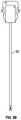
- FIG. 6is an illustrative drawing showing an example surgical tool in accordance with some embodiments.
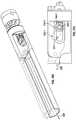
- FIG. 7Ais an illustrative partially transparent side view of a surgical tool assembly in accordance with some embodiments.
- FIG. 7Bis an illustrative partially transparent side view of the distal portion of the surgical tool assembly of FIG. 7A , enlarged to show additional details in accordance with some embodiments.
- FIG. 8is an illustrative exploded view of the second jaw in accordance with some embodiments.
- FIG. 9is an illustrative exploded view of the first and second jaws including a cam mechanism to open and close the jaws in accordance with some embodiments.
- FIGS. 10A-10Care illustrative partially transparent upper-side perspective views of the jaws and base portions of an end effector in accordance with some embodiments in open ( FIG. 10A ), partially closed ( FIG. 10B ) and closed ( FIG. 10C ) positions in accordance with some embodiments.
- FIGS. 11A-11Care enlarged side views of the first cam follower slot and the first roller cam disposed therein abutting a cam follower distal edge ( FIG. 11A ), abutting cam follower side edges ( FIG. 11B ) and abutting a cam follower proximal edge ( FIG. 11C ) in accordance with some embodiments.
- FIG. 12is an illustrative cross-sectional view of a portion of the surgical tool assembly of FIGS. 7A-7B showing details of the cam drive cable flexible segment traversing the wrist and also showing a staple driver drive cable segment traversing the wrist, in accordance with some embodiments.
- FIG. 13is an illustrative partially transparent perspective view of a portion of the surgical tool assembly of FIGS. 1A-1B showing details of the cam drive cable flexible segment and wrist control cable segments, in accordance with some embodiments.
- FIG. 1is an illustrative plan view of a teleoperated surgical system system 10 , typically used for performing a minimally invasive diagnostic or surgical procedure on a Patient 12 who is lying down on an Operating table 14 .
- the systemcan include a Surgeon's Console 16 for use by a Surgeon 18 during the procedure.
- One or more Assistants 20may also participate in the procedure.
- the teleoperated surgical system 10can further include a Patient Side Cart 22 and an Electronics Cart 24 .
- the Patient Side Cart 22can manipulate at least one removably coupled tool assembly 26 (hereinafter also referred to as a “tool”) through a minimally invasive incision in the body of the Patient 12 while the Surgeon 18 views the surgical site through the Console 16 .
- An image of the surgical sitecan be obtained by an endoscope 28 , such as a stereoscopic endoscope, which can be manipulated by the Patient Side Cart 22 to orient the endoscope 28 .
- the Electronics Cart 24can be used to process the images of the surgical site for subsequent display to the Surgeon 18 through the Surgeon's Console 16 .
- the number of surgical tools 26 used at one timewill generally depend on the diagnostic or surgical procedure and the space constraints within the operating room among other factors.
- FIG. 2is an illustrative perspective view of the Surgeon's Console 16 .
- the Surgeon's Console 16includes a left eye display 32 and a right eye display 34 for presenting the Surgeon 18 with a coordinated stereo view of the surgical site that enables depth perception.
- the Console 16further includes one or more input control devices 36 , which in turn cause the Patient Side Cart 22 (shown in FIG. 1 ) to manipulate one or more tools.
- the input control devices 36can provide the same degrees of freedom as their associated tools 26 (shown in FIG. 1 ) to provide the Surgeon with telepresence, or the perception that the input control devices 36 are integral with the tools 26 so that the Surgeon has a strong sense of directly controlling the tools 26 .
- position, force, and tactile feedback sensorsmay be employed to transmit position, force, and tactile sensations from the tools 26 back to the Surgeon's hands through the input control devices 36 .
- FIG. 3is an illustrative perspective view of the Electronics Cart 24 .
- the Electronics Cart 24can be coupled with the endoscope 28 and can include a processor to process captured images for subsequent display, such as to a Surgeon on the Surgeon's Console, or on another suitable display located locally and/or remotely.
- the Electronics Cart 24can process the captured images to present the Surgeon with coordinated stereo images of the surgical site.
- Such coordinationcan include alignment between the opposing images and can include adjusting the stereo working distance of the stereoscopic endoscope.
- FIG. 4is an illustrative bock diagram diagrammatically representing functional relationships among components of a teleoperated surgery system 50 (such as system system 10 of FIG. 1 ).
- a Surgeon's Console 52(such as Surgeon's Console 16 in FIG. 1 ) can be used by a Surgeon to control a Patient Side Cart (Surgical Robot) 54 (such as Patent Side Cart 22 in FIG. 1 ) during a minimally invasive procedure.
- the Patient Side Cart 54can use an imaging device, such as a stereoscopic endoscope, to capture images of the procedure site and output the captured images to an Electronics Cart 56 (such as the Electronics Cart 24 in FIG. 1 ).
- an imaging devicesuch as a stereoscopic endoscope
- the Electronics Cart 56can process the captured images in a variety of ways prior to any subsequent display.
- the Electronics Cart 56can overlay the captured images with a virtual control interface prior to displaying the combined images to the Surgeon via the Surgeon's Console 52 .
- the Patient Side Cart 54can output the captured images for processing outside the Electronics Cart 56 .
- the Patient Side Cart 54can output the captured images to a processor 58 , which can be used to process the captured images.
- the imagescan also be processed by a combination the Electronics Cart 56 and the processor 58 , which can be coupled together to process the captured images jointly, sequentially, and/or combinations thereof.
- One or more separate displays 60can also be coupled with the processor 58 and/or the Electronics Cart 56 for local and/or remote display of images, such as images of the procedure site, or other related images.
- FIGS. 5A-5Bare illustrative drawings showing a Patient Side Cart 22 and a surgical tool 62 , respectively in accordance with some embodiments.
- the surgical tool 62is an example of the surgical tools 26 .
- the Patient Side Cart 22 shownprovides for the manipulation of three surgical tools 26 and an imaging device 28 , such as a stereoscopic endoscope used for the capture of images of the site of the procedure. Manipulation is provided by teleoperated mechanisms having a number of robotic joints.
- the imaging device 28 and the surgical tools 26can be positioned and manipulated through incisions in the patient so that a kinematic remote center is maintained at the incision to minimize the size of the incision.
- Images of the surgical sitecan include images of the distal ends of the surgical tools 26 when they are positioned within the field-of-view of the imaging device 28 .
- FIG. 6is an illustrative drawing showing an example surgical tool 70 that includes a proximal chassis 72 , an instrument shaft 74 , and a distal end effector 76 having a jaw 78 that can be articulated to grip a patient tissue.
- the proximal chassisincludes input couplers that are configured to interface with and be driven by corresponding output couplers of the Patient Side Cart 22 .
- the input couplersare drivingly coupled with drive shafts that are disposed within the instrument shaft 74 .
- the drive shaftsare drivingly coupled with the end effector 76 .
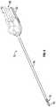
- FIG. 7Ais an illustrative partially transparent side view of a surgical tool assembly 200 with first and second jaws 214 , 216 shown in a partially open position in accordance with some embodiments.
- FIG. 7Bis an illustrative partially transparent side view of the distal portion of the surgical tool assembly of FIG. 7A , enlarged to show additional details in accordance with some embodiments.
- the tool assembly 200includes a proximal actuation assembly 202 , a main shaft 206 , a two degree of freedom (2-dof) wrist 208 , shown partially transparent using dashed lines, and an end effector 210 that includes the first and second jaws 214 , 216 .
- the end effector 210includes an end effector base 212 coupled to a distal side of the 2-dof wrist 208 , a first articulable jaw 214 and a stationary second jaw 216 .
- the first jaw 214has a distal end 214 - 1 and a proximal end 214 - 2 .
- the second jaw 216also has a distal end 216 - 1 and a proximal end 216 - 2 .
- the end effector base 212includes a pivot pin 217 rotatably secured to the end effector base 212 between a proximal end of the first jaw 214 and first and second lever arms 320 - 1 , 320 - 2 (only one visible), about which the proximal end of the first jaw 214 and the lever arms pivots to achieve opening and closing movement of the first jaw 214 relative to the second jaw 216 .
- a pivot pin 217rotatably secured to the end effector base 212 between a proximal end of the first jaw 214 and first and second lever arms 320 - 1 , 320 - 2 (only one visible), about which the proximal end of the first jaw 214 and the lever arms pivots to achieve opening and closing movement of the first jaw 214 relative to the second jaw 216 .
- the first jaw 214is rotated to a position in which distal ends 214 - 1 , 216 - 1 of the first and second jaws 214 , 216 are spaced apart sufficiently so that the jaws can be more easily maneuvered within a surgical site to encompass anatomical tissue (not shown) between them without actually clamping the tissue in place between them.
- the main shaft 206is indicated transparent using dashed lines to reveal a rigid plunger 280 that is transversely centered inside the main shaft and moveable parallel to a longitudinal axis of the main shaft 206 .
- the plunger 280includes an elongated plunger housing 282 operatively coupled to a distal cam drive member 344 (only a portion shown) that moves in unison with the rigid plunger 280 and passes through the wrist 208 , and that in turn, is operatively connected to a cam assembly 284 used to open and close the jaws 214 , 216 in response to longitudinal axial movement of the plunger 280 within the main shaft 206 .
- the drive member 344includes a cable.
- the drive member 344includes a composite structure or a closed collided spring with a return cable, for example. Movement of the plunger 280 is controlled using one or more motors within the actuation assembly 202 .
- a first motor 281 pivotally mounted on pin 283pushes and pulls on the plunger 280 to move it axially within the shaft 206 .
- a second motor 285rotates a rotational drive cable 292 , described below, which rotatably drives a worm gear 293 , which in turn, drives a staple pusher 244 through a staple cartridge 218 .
- the actuation assembly 202is operatively coupled with the wrist 208 so as to selectively reorient the end effector 210 relative to the main shaft 206 in two dimensions, referred to as pitch and yaw, and also is operatively coupled with the end effector 210 so as to actuate one or more end effector features, such as rotation of the first jaw 214 about the pivot pin 217 to open and close the first jaw 214 relative to the end effector base 212 and the second jaw 216 .
- the wrist 208is shown partially transparent using dashed lines to show a wrist bearing 346 .
- wrist control cableswhich include flexible distal cam drive cable segments coupled with more rigid proximal hypotubes, are used to operatively couple the actuation assembly 202 with the wrist 208 so as to cause 2-dof movement of the end effector 210 .
- the wrist control cablesare routed between the actuation assembly 202 and the wrist 208 within the plunger housing 282 , within the main shaft 206 .
- the cam drive member 344passes through the wrist bearing 346 (extension through the wrist bearing not shown), and can flex to reorient its path in response to 2-dof wrist movements.
- the cam drive cablewhile in a flexed condition, due to 2-dof wrist movement for example, can move in unison with the plunger 280 deliver force to the cam assembly 284 to control the opening and closing of the jaws.
- the cam assembly 284includes levering-guide rollers 336 - 1 , 336 - 2 that act as roller cams and corresponding levering-guide roller surfaces 332 - 1 , 332 - 2 that act as levering-guide cam followers.
- the cam assembly 284also includes linear-guide rollers 334 - 1 , 334 - 2 that act as linear-guide cams, and corresponding linear-guide roller guide surfaces 326 - 1 , 326 - 2 , that act as linear-guide cam followers.
- the first lever arm 320 - 1is shown partially transparent using dashed lines to reveal a roller guide 326 - 1 formed in the base 212 disposed behind it and to better reveal the linear-guide roller 334 - 1 that moves in contact with the linear-guide roller guide surface 326 - 1 .
- the end effector 210includes a surgical stapler.
- the first and second jaws 214 , 216are disposed parallel to each other spaced apart by an amount to accommodate anatomical tissue (not shown) that may be clamped between them.
- the first jaw 214includes an anvil 220 that faces the second jaw 216 .
- staplesare disposed in a cartridge 218 (indicated by dashed lines) described below, are deformed against the anvil 220 to staple together tissue (not shown) disposed between the first and second jaws 214 , 216 .
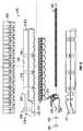
- FIG. 8is an illustrative exploded view of the second jaw 216 in accordance with some embodiments.
- the second jaw 216includes an elongated stapler cartridge 218 seated within a stapler cartridge support channel 221 , staples 242 , staple pushers 244 , a drive shuttle 246 , a knife 247 , a lead screw 293 , a thrust washer 262 and a lead screw nut 264 used to secure the lead screw.
- the elongated cartridge 218includes a proximal end 218 - 1 and a distal end 218 - 2 .
- the cartridgeincludes cartridge outer sidewalls 234 and an upper surface 236 .
- the cartridge 218carries fasteners, e.g., staples 242 to be used to attach tissue during a surgical procedure.
- the stapler cartridge 218defines a central longitudinal cartridge slot 238 that extends through the cartridge 218 and extends along substantially its entire length.
- the stapler cartridge 218also defines multiple laterally spaced rows of staple retention slots 240 that extend longitudinally along one side of the first cartridge slot 238 and defines multiple laterally rows of spaced staple retention slots 240 that extend longitudinally along an opposite side of the first cartridge slot 238 .
- Each staple retention slot 240is sized to receive a staple 242 .
- the second jaw 216 containing a full load of staplescooperates with a surface of the anvil surface 220 facing the second jaw 216 , so as to deform staples so as to fasten them to staple anatomical tissue (not shown) disposed between the jaws when they are in a closed position.
- the spent cartridge 218can be removed and may be replaced by a replacement with a fully loaded stapler cartridge 218 .
- the pusher shuttle 246includes a plurality of inclined upstanding cam wedges 248 and the knife 247 upstanding between and proximal to the cam wedges 248 .
- the cartridge 218defines multiple longitudinal pusher slots (not shown) in its underside along which the cam wedges 248 can slide with the knife upstanding from and sliding within the first cartridge slot 238 .
- pusher shuttle 246translates through the longitudinal pusher slots formed in an underside of the cartridge 218 to advance the cam wedges 248 into sequential contact with pushers 244 within the longitudinally spaced retention slots 240 , to cause pushers 244 to translate vertically within retention slots 240 , and to urge fasteners 242 from retention slots 240 into the staple deforming cavities (not shown) formed within the anvil 220 of the first jaw 214 .
- the pusher shuttle 246translates longitudinally, it pushes up fasteners 242 , which are deformed against the anvil 220 .
- FIG. 9is an illustrative exploded view of a cam mechanism to open and close the jaws in accordance with some embodiments.
- the proximal end 214 - 2 of the first jaw 214is integrally secured to opposed facing first and second lever arms 320 - 1 , 320 - 2 that extend proximal to the first jaw 214 .
- the second jaw 216is integrally secured to the end effector base 212 .
- the first and second first and second lever arms 320 - 1 , 320 - 2 jawsdefine first pivot bores 217 - 1 , 217 - 2 and the second jaw 216 defines a third pivot bore 217 - 3 that are aligned to receive a pivot axle 217
- the pivot axle 217is received in the pivot bores, 217 - 1 , 217 - 2 , 217 - 3 to rotatably mount the first jaw 214 and the first and second lever arms 320 - 1 , 320 - 2 to the base 212 with the distal end 214 - 1 of the first jaw 214 extending distally to from the base 212 opposite the second jaw 216 , and with the first and second lever arms 320 - 1 , 320 - 2 extending along opposite sides of the base 212 .
- the base 212defines first and second linear roller guide slots 324 - 1 , 324 - 2 (only one visible.) that are aligned parallel to a longitudinal axis 325 of the second jaw 216 and that are bounded by first and second roller guide surfaces 326 - 1 , 326 - 2 . (only one roller guide surface visible)
- the basealso defines a center slot 327 bounded by an surface 328 between the first and second roller guide slots 324 - 1 , 324 - 2 and the first and second roller guide surfaces 326 - 1 , 326 - 2 .
- the first and second lever arms 320 - 1 , 320 - 2define first and second cam follower slots 330 - 1 , 330 - 2 that are bounded by the first and second levering cam follower surfaces 332 - 1 , 332 - 2 .
- a levering forceis imparted by a pair of levering-guide rollers 336 - 1 , 336 - 2 to move the first jaw 214 between open and closed positions.
- the levering surfacesare covered.
- the levering cam follower surfaces 332 - 1 , 332 - 2are straight but configured at an angle to a pair of linear roller guide slots 324 - 1 , 324 - 2 .
- a cam pin 349includes an axle 338 that coaxially mounts a pair of linear-guide rollers 334 - 1 , 334 - 2 and a pair of levering-guide rollers 336 - 1 , 336 - 2 .
- the cam pinis mounted on a bearing 342 .
- the cam pinis disposed so that first and second linear-guide rollers 334 - 1 , 334 - 2 engage the first and second linear roller guide slots 324 - 1 , 324 - 2 and so that the first and second levering-guide rollers 336 - 1 , 336 - 2 engage the first and second cam follower slots.
- first and second linear roller guide slots 324 - 1 , 324 - 2each is sized to receive one of a pair of linear-guide rollers 334 - 1 , 334 - 2 that are rotatably moveable to traverse its length.
- first and second cam follower slots 330 - 1 , 330 - 2each is sized to receive one of a pair of levering-guide rollers 336 - 1 , 336 - 2 that are rotatably moveable to traverse its length.
- the pair of rollers 334 - 1 , 334 - 2 and the pair of roller cams 336 - 1 , 336 - 2are rotatably mounted, coaxially, to an axle 338 , which acts as a bearing for the pair of roller cams 334 - 1 , 334 - 2 and for the pair of roller cams 336 - 1 , 336 - 2 . More particularly, the pair of roller cams 336 - 1 , 336 - 2 are mounted to the axle 338 between the pair of levering-guide roller cams 336 - 1 , 336 - 2 .
- An axle bearing 340is mounted within the center slot 327 defined by surface 328
- the axle 338is mounted within in a bore 342 formed in the axle bearing 340 to permit rotation of the linear-guide rollers 334 - 1 , 334 - 2 and the levering-guide rollers 336 - 1 , 336 - 2 .
- a flexible distal cam drive cable segments 344 - 1extends through the wrist bearing 346 in the 2-dof wrist 208 and into the center slot 327 and acts as a linear drive to drive the axle bearing 340 , in a linear motion, parallel to the second jaw axis 325 within the center slot 327 .
- the cam drive member 344is moveable axially, through force applied by the first motor 281 , within the center slot 327 in a direction parallel to the longitudinal axis 325 of the second jaw 216 .
- a distal end of the cam drive member 344is secured proximal to the axle bearing 340 so that the axle bearing 342 , and the linear-guide rollers 334 - 1 , 334 - 2 and levering-guide roller guides 336 - 1 , 336 - 2 mounted thereto, move in unison with axial movement of the cam drive member segment 344 .
- axle bearing 340acts as a cam driver since it mounts the axle 338 on which the linear-guide rollers 334 - 1 , 334 - 2 and the roller cams 336 - 1 , 336 - 2 are rotatably mounted, and linear motion of the axle bearing 340 within the center slot 327 drives the cam action of the roller cams 336 - 1 , 336 - 2 .
- roller guide surfaces 326 - 1 , 326 - 2act as cam guide surfaces that guide movement direction of the linear-guide rollers 334 - 1 , 334 - 2 and the levering-guide rollers 336 - 1 , 336 - 2 coaxially mounted to the axle 338 .
- the second jawis integrally secured to and is an integral portion of the base and that direction of linear motion of the axle bearing within the center slot and direction of linear motion of the roller cams along the linear roller guide surfaces 326 - 1 , 326 - 2 are parallel to a longitudinal axis 325 of the second jaw 216 .
- FIGS. 10A-10Care illustrative partially transparent upper-side perspective views of the jaws and base portions of an end effector in accordance with some embodiments in open ( FIG. 10A ), partially closed ( FIG. 10B ) and closed ( FIG. 10C ) positions in accordance with some embodiments.
- the first jaw 214 and the first lever arm 320 - 1are shown partially transparent, using dashed lines, so as to reveal structures disposed behind them; the second lever arm 320 - 2 is not visible.
- the second jaw 216is shown with the cartridge 218 removed so as to simplify the drawing.
- FIG. 11A-11Care enlarged partially transparent enlarged side views of the first cam follower slot 330 - 1 and the first levering-guide roller cam 336 - 1 disposed therein abutting a levering cam follower distal end edge ( FIG. 11A ), abutting only levering cam follower side edges ( FIG. 11B ) and abutting a levering cam follower proximal end edge ( FIG. 11C ) in accordance with some embodiments.
- the enlarged portion of the first lever arm 320 - 1is shown partially transparent, using dashed lines, so as to reveal structures disposed behind it.
- the cam drive member 344drives the pair of levering-guide rollers 336 - 1 , 336 - 2 (only the first roller cam visible) parallel to the longitudinal axis 325 of the second jaw 216 .
- the cable drive 344imparts a linear motion to the bearing 340 , which imparts a linear motion to the linear-guide rollers 334 - 1 , 334 - 2 within the linear roller guide slots 324 - 1 , 324 - 2 bounded by the first and second linear roller guide surfaces 326 - 1 , 326 - 1 .
- the levering-guide rollers 336 - 1 , 336 - 2 coaxially mounted to axle 338move in a linear direction in unison with the roller cams 334 - 1 , 334 - 2 within levering roller guide slots 330 - 1 , 330 - 2 bounded by the first and second levering roller guide surfaces 332 - 1 , 332 - 2 .
- the first and second levering roller guides 332 - 1 , 332 - 2each includes a respective distal portion 347 - 1 , 347 - 2 and respective proximal portion 348 - 1 , 348 - 2 .
- the distal portion 347 - 1 , 347 - 2 of each levering roller guide 332 - 1 , 332 - 2is disposed relative to the pivot 217 so that interaction between the levering-guide roller cams 336 - 1 , 336 - 2 and the distal portions 347 - 1 , 347 - 2 of the levering roller guides 332 - 1 , 332 - 2 imparts a lever force to cause the first jaw 214 to rotate in a direction toward the second jaw 216 so as to close the jaws.
- each levering roller guide 332 - 1 , 332 - 2is disposed relative to the pivot 217 so that interaction between the roller cams 336 - 1 , 336 - 2 and the proximal portions 348 - 1 , 348 - 2 of the levering roller guides 332 - 1 , 332 - 2 imparts a lever force to cause the first jaw 214 to rotate in a direction away from the second jaw 216 so as to open the jaws.
- the base 212defines the first and second elongated linear roller guide slots 324 - 1 , 324 - 2 each sized to receive one of the pair of linear-guide rollers 334 - 1 , 334 - 2 .
- the first and second linear roller guide slots 324 - 1 , 324 - 2constrain the first and second roller guides 334 - 1 , 334 - 2 to movement parallel to the longitudinal axis 325 of the second jaw 216 .
- the first and second roller linear-guide rollers 334 - 1 , 334 - 2are mounted coaxially with the first and second rollers 336 - 1 , 336 - 2 so as to guide the levering-guide rollers 336 - 1 , 336 - 2 in a linear motion parallel to the longitudinal axis 325 of the second jaw 216 while the levering-guide rollers 336 - 1 , 336 - 2 interact with the pair of levering roller guides 332 - 1 , 332 - 2 to impart rotation motion to the first jaw 314 about the pivot 217 .
- first and second linear roller guide slots 324 - 1 , 324 - 2are aligned parallel to the longitudinal axis 325 of the second jaw 216 and are bounded by first and second linear roller guide surfaces 326 - 1 , 326 - 2 .
- the first and second linear guide slots 324 - 1 , 324 - 2are disposed on opposed sides of the base 212 and are aligned with each other.
- the first and second linear roller guide surfaces 326 - 1 , 326 - 2each include a respective distal end portion 351 - 1 and a respective proximal end portion 352 - 1 .
- the first and second linear roller guide surfaces 326 - 1 , 326 - 2each includes a corresponding pair of opposed roller guide side edges uniformly spaced apart from each other along their lengths to constrain movement of a linear-guide roller guide roller 334 - 1 , 334 - 2 received between them to a linear path that is parallel to the longitudinal axis 325 of the second jaw 216 and that extends between its distal end portion 351 - 1 , 351 - 2 and its proximal end portion 352 - 1 , 352 - 2 .
- the linear roller guide surface distal end portions 351 - 1 , 351 - 2define respective distal stop surfaces to constrain distal-direction movement of the roller cams 334 - 1 , 334 - 2 .
- the linear roller guide surface proximal end portions 352 - 1 , 352 - 2define respective proximal stop surfaces to constrain proximal direction movement of the roller cams 334 - 1 , 334 - 2 .
- Each of the first and second roller levering roller guide surfaces 332 - 1 , 332 - 2includes a respective pair of opposed cam follower side edges uniformly spaced apart from each other along their lengths the between the roller cam follower distal end portions 347 - 1 , 347 - 2 and the roller cam follower proximal end portions 348 - 1 , 348 - 2 .
- the levering roller cam surface distal end portions 347 - 1 , 347 - 2define respective distal stop surfaces to constrain distal-direction movement of the levering-guide roller cams 336 - 1 , 336 - 2 .
- levering roller cam surface proximal end portions 348 - 1 , 348 - 2define respective proximal stop surfaces to constrain proximal direction movement of the levering-guide roller cams 336 - 1 , 336 - 2 .
- the first and second linear roller guide surfaces 326 - 1 , 326 - 2constrain both the linear-guide roller guides 334 - 1 , 334 - 1 and the roller cams 336 - 1 , 336 - 2 to follow a path parallel to the axis 325 of the second jaw 216 .
- the first and second levering roller guide surfaces 332 - 1 , 332 - 2 formed in the base 212are inclined relative to the first and second linear roller guide surfaces 326 - 1 , 326 - 2 formed in the first and second lever arms 320 - 1 , 320 - 2 such that during linear motion of the linear-guide rollers 334 - 1 , 334 - 2 and the roller cams 336 - 1 , 336 - 2 parallel to the axis 325 , the first and second roller levering cams surfaces 336 - 1 , 336 - 2 impart a lever force to the first and second levering-guide rollers 336 - 1 , 336 - 2 causing rotation of the first arm 214 and of the first and second lever arms 320 - 1 , 320 - 2 about the pivot axis 217 .
- first and second levering roller guide surfaces 332 - 1 , 332 - 2are contoured so as to amplify the lever force imparted by the roller cams 336 - 1 , 336 - 2 when they are disposed in either the distal end portions 347 - 1 , 347 - 2 or the proximal end portions 348 - 1 , 348 - 2 of the first and second levering roller guide surfaces 332 - 1 , 332 - 2 .
- the first and second levering roller guide slots 330 - 1 , 330 - 2 and the opposed levering roller guide surface side edges 332 - 1 , 332 - 2have a curved contour to steer the levering-guide rollers 336 - 1 , 336 - 2 to and from the levering roller guide surface' distal end portions 347 - 1 , 347 - 2 and to and from the levering roller guide surfaces' proximal end portions 348 - 1 , 348 - 2 .
- roller cams 336 - 1 , 336 - 2interact with the roller levering roller guide surfaces 332 - 1 , 332 - 2 to impart rotation motion to the lever arms 320 - 1 , 320 - 2 and to the first arm 214 .
- FIG. 10A and FIG. 10Billustrate that during passage of the roller cams 336 - 1 , 336 - 2 within portions of the first and second levering roller guide surfaces 332 - 1 , 332 - 2 that are between the proximal and distal end portions, the roller cams 336 - 1 , 336 - 2 interact with the roller levering roller guide surfaces 332 - 1 , 332 - 2 to impart rotation motion to the lever arms 320 - 1 , 320 - 2 and to the first arm 214 .
- levering-guide rollers 336 - 1 , 336 - 2transfer to the levering roller guide surface distal edges 347 - 1 , 347 - 2 a lever force that matches the distal direction force applied by the cam drive member 344 to the axle bearing 342 , resulting in the exerting of a maximal jaw opening rotation force to the first jaw 214 .
- levering-guide roller cams 336 - 1 , 336 - 2transfer to the cam follower proximal edges 348 - 1 , 348 - 2 a lever force that matches the proximal direction force applied by the cam drive member 344 to the axle bearing 342 , resulting in the exerting of a maximal jaw closing rotation force to the first jaw 214 .
- FIG. 12is an illustrative cross-sectional view of a portion of the surgical tool assembly of FIGS. 7A-7B showing details of the cam drive member 344 traversing the wrist 208 and also showing a staple driver drive cable 902 traversing the wrist 208 in accordance with some embodiments.
- the plunger 280defines a centrally disposed cam drive cable passage 286 in which the cam drive member 344 is attached so that the cam drive member 344 moves in unison with axial movement of the plunger 280 within the main shaft 206 .
- the center passage 286 defined by the plungeris aligned with a center passage 288 defined through the wrist bearing 346 through which the flexible cam drive 344 passes and moves freely in unison with axial movement of the plunger 280 within the main shaft 206 .
- the cam drive member 344extends distally from the wrist bearing and is secured to a proximal side of to the axle bearing 340 , which moves in unison with it as explained above.
- the plunger 280also defines a staple drive cable passage 290 in which a rotatable flexible rotational drive cable 292 extends between the proximal actuation assembly 202 and a lead screw 293 .
- the flexible staple drive cable 292 and the lead screw 293are axially secured so that they rotate in unison; rotation imparted by the second motor 285 to the rotational drive cable 292 is imparted to lead screw 293 .
- the lead screw 293engages with a complementary threaded surface of the staple pusher 244 such that that rotation of the lead screw 293 results in linear motion of the staple pusher 244 in a distal direction along the second jaw axis 325 whereby staples are driven for deformation against the anvil 221 as described above.
- the staple drive cable 292includes a rotational torque coil (sometimes referred to as a ‘speedo cable’) to impart a rotational force to the lead screw, which also permits two-degree of freedom flexing of the rotational drive cable 292 in a region 294 where it traverses the wrist 208 portion.
- the staple drive cable 292can include a wound up coil such as a closed coiled spring that is configured to provide toque when rotated.
- a two-degree of freedom flexible coupling membersuch as a cardan, a flexible drive shaft, a U-joint, a double U-joint, or snake-style linkages secures the rotational drive cable 292 to the lead screw 293 in the region 294 , to permit two-degree of freedom flexing, while the rotational drive cable 292 imparts an off-axis rotation force to the lead screw 293 , for example.
- FIG. 13is an illustrative partially transparent perspective view of a portion of the surgical tool assembly of FIGS. 7A-7B showing details of the flexible cam drive member 344 traversing the wrist 208 in accordance with some embodiments.
- the wristincludes a ball joint bearing 346 that depends from a distal end of the shaft 206 .
- Coupling pins 402rotatably mount the base portion 212 of the end effector 210 to the bearing 346 for motion in two degrees of freedom (2-dof). More specifically, wrist coupling pin 402 rotatably mounts the bearing 346 to the base 212 so as to permit rotation of the end effector 210 in a first degree of freedom relative to the bearing 346 .
- the base 212defines transverse slots 404 that permit rotation of the end effector 210 in a second degree of freedom relative to the bearing 346 .
- Wrist control cable segments 296 - 1 to 296 - 4extend through the main shaft 206 and the plunger 280 secured within wrist 208 to control wrist movement, in accordance with some embodiments.
- the main shaft 206 and the base 212are shown partially transparent using dashed lines to show structures within them.
- the wrist control cable segments 296 - 1 to 296 - 4extend into the wrist 208 to attachments 298 - 1 to 298 - 4 used to secure them to the wrist 208 .
- the end effector 210which includes the first and second jaws 214 , 216 is moveable in two degrees of freedom (2-dof) in response to selective tension and corresponding relaxation forces provided to the wrist control cables.
- the plunger 280defines passages 298 - 1 , 298 - 2 (only one visible) to permit passage of first and second wrist cables 296 - 1 , 296 - 2 .
- the passage 290is sized large enough to allow passage of third and fourth wrist cables 296 - 3 , 296 - 4 in addition to the rotational drive cable 292 .
- U.S. Pat. No. 8,852,174(filed Nov. 12, 2010) issued to Burbank, which is incorporated herein in its entirety by this reference, discloses prior surgical tools that include two degree of freedom wrists.
Landscapes
- Health & Medical Sciences (AREA)
- Surgery (AREA)
- Life Sciences & Earth Sciences (AREA)
- Biomedical Technology (AREA)
- Nuclear Medicine, Radiotherapy & Molecular Imaging (AREA)
- Engineering & Computer Science (AREA)
- Heart & Thoracic Surgery (AREA)
- Medical Informatics (AREA)
- Molecular Biology (AREA)
- Animal Behavior & Ethology (AREA)
- General Health & Medical Sciences (AREA)
- Public Health (AREA)
- Veterinary Medicine (AREA)
- Ophthalmology & Optometry (AREA)
- Surgical Instruments (AREA)
Abstract
Description
This patent application is a U.S. National Stage Filing under 35 U.S.C. 371 from International Application No. PCT/US2016/059649, filed on Oct. 31, 2016, and published as WO 2017/083130 A1 on May 18, 2017, which claims priority to and the benefit of the filing date of U.S.Provisional Patent Application 62/255,150, entitled “PUSH-PULL STAPLER WITH Two DEGREE OF FREEDOM WRIST” filed Nov. 13, 2015, each of which is incorporated by reference herein in its entirety.
Minimally invasive surgical techniques are aimed at reducing the amount of extraneous tissue that is damaged during diagnostic or surgical procedures, thereby reducing patient recovery time, discomfort, and deleterious side effects. As a consequence, the average length of a hospital stay for standard surgery may be shortened significantly using minimally invasive surgical techniques. Also, patient recovery times, patient discomfort, surgical side effects, and time away from work may also be reduced with minimally invasive surgery.
Minimally invasive teleoperated surgical systems have been developed to increase a surgeon's dexterity when working on an internal surgical site, as well as to allow a surgeon to operate on a patient from a remote location (outside the sterile field). In a teleoperated surgical system, the surgeon is often provided with an image of the surgical site at a control console. While viewing a three dimensional image of the surgical site on a suitable viewer or display, the surgeon performs the surgical procedures on the patient by manipulating master input or control devices of the control console. Each of the master input devices controls the motion of a servo-mechanically actuated/articulated surgical instrument. During the surgical procedure, the teleoperated surgical system can provide mechanical actuation and control of a variety of surgical instruments or tools having end effectors that perform various functions for the surgeon, for example, holding or driving a needle, grasping a blood vessel, dissecting tissue, stapling tissue, or the like, in response to manipulation of the master input devices.
In one aspect, a surgical instrument includes a first jaw having a distal end and a proximal end, wherein the proximal end of the first jaw is attached to a lever arm that includes a levering cam slot having a proximal portion and a distal portion. A second jaw has a distal end and a proximal end, wherein the proximal end of the second jaw is secured to a base that includes a linear cam slot aligned with a longitudinal axis of the second jaw axis and having a proximal portion and a distal portion. A pivot rotatably mounts the first jaw to the second jaw. A pivot axis extends between the first jaw and the lever arm. A cam pin is configured to extend through and engage the levering cam slot and the linear cam slot. A linear drive member is operatively coupled to drive the cam pin to follow the linear cam slot. The distal portion of the levering cam slot is disposed such that the cam pin imparts a lever force upon the lever arm that rotates the first jaw away from the second jaw when the cam pin contacts the distal portion of the levering cam slot. The proximal portion of the levering cam slot is disposed such that the cam pin imparts a lever force upon the lever arm that rotates the first jaw toward the second jaw when the cam pin contacts the proximal end portion of the levering cam slot.
Aspects of the present disclosure are best understood from the following detailed description when read with the accompanying figures. It is emphasized that, in accordance with the standard practice in the industry, various features are not drawn to scale. In fact, the dimensions of the various features may be arbitrarily increased or reduced for clarity of discussion. In addition, the present disclosure may repeat reference numerals and/or letters in the various examples. This repetition is for the purpose of simplicity and clarity and does not in itself dictate a relationship between the various embodiments and/or configurations discussed.
The following description is presented to enable any person skilled in the art to create and use a push-pull stapler with two-degree of freedom wrist for use in surgery. Various modifications to the embodiments will be readily apparent to those skilled in the art, and the generic principles defined herein may be applied to other embodiments and applications without departing from the spirit and scope of the inventive subject matter. Moreover, in the following description, numerous details are set forth for the purpose of explanation. However, one of ordinary skill in the art will realize that the inventive subject matter might be practiced without the use of these specific details. In other instances, well-known machine components, processes and data structures are shown in block diagram form in order not to obscure the disclosure with unnecessary detail. Identical reference numerals may be used to represent different views of the same item in different drawings. Flow diagrams in drawings referenced below are used to represent processes. A computer system may be configured to perform some of these processes. Modules within flow diagrams representing computer implemented processes represent the configuration of a computer system according to computer program code to perform the acts described with reference to these modules. Thus, the inventive subject matter is not intended to be limited to the embodiments shown, but is to be accorded the widest scope consistent with the principles and features disclosed herein.
Referring now to the drawings, in which like reference numerals represent like parts throughout the several views,FIG. 1 is an illustrative plan view of a teleoperatedsurgical system system 10, typically used for performing a minimally invasive diagnostic or surgical procedure on aPatient 12 who is lying down on an Operating table14. The system can include a Surgeon'sConsole 16 for use by aSurgeon 18 during the procedure. One ormore Assistants 20 may also participate in the procedure. The teleoperatedsurgical system 10 can further include aPatient Side Cart 22 and anElectronics Cart 24. ThePatient Side Cart 22 can manipulate at least one removably coupled tool assembly26 (hereinafter also referred to as a “tool”) through a minimally invasive incision in the body of thePatient 12 while theSurgeon 18 views the surgical site through theConsole 16. An image of the surgical site can be obtained by anendoscope 28, such as a stereoscopic endoscope, which can be manipulated by thePatient Side Cart 22 to orient theendoscope 28. TheElectronics Cart 24 can be used to process the images of the surgical site for subsequent display to theSurgeon 18 through the Surgeon'sConsole 16. The number ofsurgical tools 26 used at one time will generally depend on the diagnostic or surgical procedure and the space constraints within the operating room among other factors.
Themain shaft 206 is indicated transparent using dashed lines to reveal arigid plunger 280 that is transversely centered inside the main shaft and moveable parallel to a longitudinal axis of themain shaft 206. As explained more fully below, theplunger 280 includes anelongated plunger housing 282 operatively coupled to a distal cam drive member344 (only a portion shown) that moves in unison with therigid plunger 280 and passes through thewrist 208, and that in turn, is operatively connected to acam assembly 284 used to open and close thejaws plunger 280 within themain shaft 206. In some embodiments, thedrive member 344 includes a cable. Alternatively, for example, thedrive member 344 includes a composite structure or a closed collided spring with a return cable, for example. Movement of theplunger 280 is controlled using one or more motors within theactuation assembly 202. In accordance with some embodiments, afirst motor 281 pivotally mounted onpin 283 pushes and pulls on theplunger 280 to move it axially within theshaft 206. Asecond motor 285 rotates arotational drive cable 292, described below, which rotatably drives aworm gear 293, which in turn, drives astaple pusher 244 through astaple cartridge 218.
In many embodiments, theactuation assembly 202 is operatively coupled with thewrist 208 so as to selectively reorient theend effector 210 relative to themain shaft 206 in two dimensions, referred to as pitch and yaw, and also is operatively coupled with theend effector 210 so as to actuate one or more end effector features, such as rotation of thefirst jaw 214 about thepivot pin 217 to open and close thefirst jaw 214 relative to theend effector base 212 and thesecond jaw 216. Thewrist 208 is shown partially transparent using dashed lines to show awrist bearing 346. In accordance with some embodiments, wrist control cables (not shown), which include flexible distal cam drive cable segments coupled with more rigid proximal hypotubes, are used to operatively couple theactuation assembly 202 with thewrist 208 so as to cause 2-dof movement of theend effector 210. As explained more fully below, the wrist control cables are routed between theactuation assembly 202 and thewrist 208 within theplunger housing 282, within themain shaft 206. Thecam drive member 344 passes through the wrist bearing346 (extension through the wrist bearing not shown), and can flex to reorient its path in response to 2-dof wrist movements. The cam drive cable, while in a flexed condition, due to 2-dof wrist movement for example, can move in unison with theplunger 280 deliver force to thecam assembly 284 to control the opening and closing of the jaws.
Thecam assembly 284 includes levering-guide rollers336-1,336-2 that act as roller cams and corresponding levering-guide roller surfaces332-1,332-2 that act as levering-guide cam followers. Thecam assembly 284 also includes linear-guide rollers334-1,334-2 that act as linear-guide cams, and corresponding linear-guide roller guide surfaces326-1,326-2, that act as linear-guide cam followers. The first lever arm320-1 is shown partially transparent using dashed lines to reveal a roller guide326-1 formed in the base212 disposed behind it and to better reveal the linear-guide roller334-1 that moves in contact with the linear-guide roller guide surface326-1.
In some embodiments, theend effector 210 includes a surgical stapler. In a closed position (not shown), the first andsecond jaws first jaw 214 includes ananvil 220 that faces thesecond jaw 216. In operation, staples are disposed in a cartridge218 (indicated by dashed lines) described below, are deformed against theanvil 220 to staple together tissue (not shown) disposed between the first andsecond jaws
Thepusher shuttle 246 includes a plurality of inclinedupstanding cam wedges 248 and theknife 247 upstanding between and proximal to thecam wedges 248. Thecartridge 218 defines multiple longitudinal pusher slots (not shown) in its underside along which thecam wedges 248 can slide with the knife upstanding from and sliding within thefirst cartridge slot 238. During operation of surgicalstapler end effector 210,pusher shuttle 246 translates through the longitudinal pusher slots formed in an underside of thecartridge 218 to advance thecam wedges 248 into sequential contact withpushers 244 within the longitudinally spacedretention slots 240, to causepushers 244 to translate vertically withinretention slots 240, and to urgefasteners 242 fromretention slots 240 into the staple deforming cavities (not shown) formed within theanvil 220 of thefirst jaw 214. As thepusher shuttle 246 translates longitudinally, it pushes upfasteners 242, which are deformed against theanvil 220. Meanwhile, theknife 247 upstands through thefirst cartridge slot 238 and cuts tissue between tissue regions stapled through action of thecam wedges 248,fasteners 242 and theanvil 221. U.S. Pat. No. 8,991,678 (filed Oct. 26, 2012) issued to Wellman et al., which is incorporated herein in its entirety by this reference, discloses a surgical stapler cartridge and its operation.
Thebase 212 defines first and second linear roller guide slots324-1,324-2 (only one visible.) that are aligned parallel to alongitudinal axis 325 of thesecond jaw 216 and that are bounded by first and second roller guide surfaces326-1,326-2. (only one roller guide surface visible) The base also defines a center slot327 bounded by ansurface 328 between the first and second roller guide slots324-1,324-2 and the first and second roller guide surfaces326-1,326-2. The first and second lever arms320-1,320-2 define first and second cam follower slots330-1,330-2 that are bounded by the first and second levering cam follower surfaces332-1,332-2. As explained more fully below, a levering force is imparted by a pair of levering-guide rollers336-1,336-2 to move thefirst jaw 214 between open and closed positions. In some embodiments the levering surfaces are covered. In an alternative embodiment, the levering cam follower surfaces332-1,332-2 are straight but configured at an angle to a pair of linear roller guide slots324-1,324-2.
Acam pin 349 includes anaxle 338 that coaxially mounts a pair of linear-guide rollers334-1,334-2 and a pair of levering-guide rollers336-1,336-2. The cam pin is mounted on a bearing342. The cam pin is disposed so that first and second linear-guide rollers334-1,334-2 engage the first and second linear roller guide slots324-1,324-2 and so that the first and second levering-guide rollers336-1,336-2 engage the first and second cam follower slots.
More particularly, the first and second linear roller guide slots324-1,324-2 each is sized to receive one of a pair of linear-guide rollers334-1,334-2 that are rotatably moveable to traverse its length. Similarly, the first and second cam follower slots330-1,330-2 each is sized to receive one of a pair of levering-guide rollers336-1,336-2 that are rotatably moveable to traverse its length. The pair of rollers334-1,334-2 and the pair of roller cams336-1,336-2 are rotatably mounted, coaxially, to anaxle 338, which acts as a bearing for the pair of roller cams334-1,334-2 and for the pair of roller cams336-1,336-2. More particularly, the pair of roller cams336-1,336-2 are mounted to theaxle 338 between the pair of levering-guide roller cams336-1,336-2. An axle bearing340 is mounted within the center slot327 defined bysurface 328 Theaxle 338 is mounted within in a bore342 formed in the axle bearing340 to permit rotation of the linear-guide rollers334-1,334-2 and the levering-guide rollers336-1,336-2. In some embodiments, a flexible distal cam drive cable segments344-1 extends through thewrist bearing 346 in the 2-dof wrist 208 and into the center slot327 and acts as a linear drive to drive theaxle bearing 340, in a linear motion, parallel to thesecond jaw axis 325 within the center slot327. Thecam drive member 344 is moveable axially, through force applied by thefirst motor 281, within the center slot327 in a direction parallel to thelongitudinal axis 325 of thesecond jaw 216. A distal end of thecam drive member 344 is secured proximal to the axle bearing340 so that the axle bearing342, and the linear-guide rollers334-1,334-2 and levering-guide roller guides336-1,336-2 mounted thereto, move in unison with axial movement of the camdrive member segment 344.
It will be appreciated that the axle bearing340 acts as a cam driver since it mounts theaxle 338 on which the linear-guide rollers334-1,334-2 and the roller cams336-1,336-2 are rotatably mounted, and linear motion of the axle bearing340 within the center slot327 drives the cam action of the roller cams336-1,336-2. It will be further appreciated that the roller guide surfaces326-1,326-2 act as cam guide surfaces that guide movement direction of the linear-guide rollers334-1,334-2 and the levering-guide rollers336-1,336-2 coaxially mounted to theaxle 338. It will be further appreciated that the second jaw is integrally secured to and is an integral portion of the base and that direction of linear motion of the axle bearing within the center slot and direction of linear motion of the roller cams along the linear roller guide surfaces326-1,326-2 are parallel to alongitudinal axis 325 of thesecond jaw 216.
Referring collectively toFIG. 9 and toFIGS. 10A-10C and toFIGS. 11A-11C , in operation, thecam drive member 344 drives the pair of levering-guide rollers336-1,336-2 (only the first roller cam visible) parallel to thelongitudinal axis 325 of thesecond jaw 216.
Thecable drive 344 imparts a linear motion to thebearing 340, which imparts a linear motion to the linear-guide rollers334-1,334-2 within the linear roller guide slots324-1,324-2 bounded by the first and second linear roller guide surfaces326-1,326-1. The levering-guide rollers336-1,336-2 coaxially mounted toaxle 338 move in a linear direction in unison with the roller cams334-1,334-2 within levering roller guide slots330-1,330-2 bounded by the first and second levering roller guide surfaces332-1,332-2. Interaction of the linear-guide rollers334-1,334-2 with the first and second levering roller guide surfaces332-1,332-2 imparts lever force to lever arms320-1,320-2 that causes a rotation motion of the about thepivot 217 that moves thefirst jaw 214 in a direction opposite to the direction of the lever force.
The first and second levering roller guides332-1,332-2 each includes a respective distal portion347-1,347-2 and respective proximal portion348-1,348-2. The distal portion347-1,347-2 of each levering roller guide332-1,332-2 is disposed relative to thepivot 217 so that interaction between the levering-guide roller cams336-1,336-2 and the distal portions347-1,347-2 of the levering roller guides332-1,332-2 imparts a lever force to cause thefirst jaw 214 to rotate in a direction toward thesecond jaw 216 so as to close the jaws. The proximal portions348-1,348-2 of each levering roller guide332-1,332-2 is disposed relative to thepivot 217 so that interaction between the roller cams336-1,336-2 and the proximal portions348-1,348-2 of the levering roller guides332-1,332-2 imparts a lever force to cause thefirst jaw 214 to rotate in a direction away from thesecond jaw 216 so as to open the jaws.
Thebase 212 defines the first and second elongated linear roller guide slots324-1,324-2 each sized to receive one of the pair of linear-guide rollers334-1,334-2. The first and second linear roller guide slots324-1,324-2 constrain the first and second roller guides334-1,334-2 to movement parallel to thelongitudinal axis 325 of thesecond jaw 216. The first and second roller linear-guide rollers334-1,334-2 are mounted coaxially with the first and second rollers336-1,336-2 so as to guide the levering-guide rollers336-1,336-2 in a linear motion parallel to thelongitudinal axis 325 of thesecond jaw 216 while the levering-guide rollers336-1,336-2 interact with the pair of levering roller guides332-1,332-2 to impart rotation motion to the first jaw314 about thepivot 217.
More specifically, the first and second linear roller guide slots324-1,324-2 are aligned parallel to thelongitudinal axis 325 of thesecond jaw 216 and are bounded by first and second linear roller guide surfaces326-1,326-2. The first and second linear guide slots324-1,324-2 are disposed on opposed sides of thebase 212 and are aligned with each other. The first and second linear roller guide surfaces326-1,326-2 each include a respective distal end portion351-1 and a respective proximal end portion352-1. The first and second linear roller guide surfaces326-1,326-2 each includes a corresponding pair of opposed roller guide side edges uniformly spaced apart from each other along their lengths to constrain movement of a linear-guide roller guide roller334-1,334-2 received between them to a linear path that is parallel to thelongitudinal axis 325 of thesecond jaw 216 and that extends between its distal end portion351-1,351-2 and its proximal end portion352-1,352-2. The linear roller guide surface distal end portions351-1,351-2 define respective distal stop surfaces to constrain distal-direction movement of the roller cams334-1,334-2. Additionally, the linear roller guide surface proximal end portions352-1,352-2 define respective proximal stop surfaces to constrain proximal direction movement of the roller cams334-1,334-2.
Each of the first and second roller levering roller guide surfaces332-1,332-2 includes a respective pair of opposed cam follower side edges uniformly spaced apart from each other along their lengths the between the roller cam follower distal end portions347-1,347-2 and the roller cam follower proximal end portions348-1,348-2. The levering roller cam surface distal end portions347-1,347-2 define respective distal stop surfaces to constrain distal-direction movement of the levering-guide roller cams336-1,336-2. Additionally, the levering roller cam surface proximal end portions348-1,348-2 define respective proximal stop surfaces to constrain proximal direction movement of the levering-guide roller cams336-1,336-2.
As explained above, in operation, the first and second linear roller guide surfaces326-1,326-2 constrain both the linear-guide roller guides334-1,334-1 and the roller cams336-1,336-2 to follow a path parallel to theaxis 325 of thesecond jaw 216. The first and second levering roller guide surfaces332-1,332-2 formed in thebase 212 are inclined relative to the first and second linear roller guide surfaces326-1,326-2 formed in the first and second lever arms320-1,320-2 such that during linear motion of the linear-guide rollers334-1,334-2 and the roller cams336-1,336-2 parallel to theaxis 325, the first and second roller levering cams surfaces336-1,336-2 impart a lever force to the first and second levering-guide rollers336-1,336-2 causing rotation of thefirst arm 214 and of the first and second lever arms320-1,320-2 about thepivot axis 217.
Moreover, the first and second levering roller guide surfaces332-1,332-2 are contoured so as to amplify the lever force imparted by the roller cams336-1,336-2 when they are disposed in either the distal end portions347-1,347-2 or the proximal end portions348-1,348-2 of the first and second levering roller guide surfaces332-1,332-2. More specifically, in accordance with some embodiments, the first and second levering roller guide slots330-1,330-2 and the opposed levering roller guide surface side edges332-1,332-2 have a curved contour to steer the levering-guide rollers336-1,336-2 to and from the levering roller guide surface' distal end portions347-1,347-2 and to and from the levering roller guide surfaces' proximal end portions348-1,348-2.
As best shown inFIG. 10B andFIG. 11B , during passage of the roller cams336-1,336-2 within portions of the first and second levering roller guide surfaces332-1,332-2 that are between the proximal and distal end portions, the roller cams336-1,336-2 interact with the roller levering roller guide surfaces332-1,332-2 to impart rotation motion to the lever arms320-1,320-2 and to thefirst arm 214. As best shown inFIG. 10A andFIG. 10A , when the roller cams336-1,336-2 abut the levering roller guide surfaces' distal edges347-1,347-2, no further rotation of the lever arms320-1,320-2 and thefirst arm 214 is possible since the roller cams have reached the distal ends347-1,347-2 of the levering roller guide surfaces332-1,332-2. Consequently, the levering-guide rollers336-1,336-2 transfer to the levering roller guide surface distal edges347-1,347-2 a lever force that matches the distal direction force applied by thecam drive member 344 to the axle bearing342, resulting in the exerting of a maximal jaw opening rotation force to thefirst jaw 214. Conversely, as best shown inFIG. 10C andFIG. 11C , when the levering-guide rollers336-1,336-2 abut the levering roller guide surface proximal edges348-1,348-2, no further rotation of the lever arms320-1,320-2 and thefirst arm 214 is possible since the roller cams have reached the proximal ends348-1,348-2 of the levering roller guide surfaces332-1,332-2. Consequently, the levering-guide roller cams336-1,336-2 transfer to the cam follower proximal edges348-1,348-2 a lever force that matches the proximal direction force applied by thecam drive member 344 to the axle bearing342, resulting in the exerting of a maximal jaw closing rotation force to thefirst jaw 214.
In accordance with some embodiments, theplunger 280 also defines a stapledrive cable passage 290 in which a rotatable flexiblerotational drive cable 292 extends between theproximal actuation assembly 202 and alead screw 293. The flexiblestaple drive cable 292 and thelead screw 293 are axially secured so that they rotate in unison; rotation imparted by thesecond motor 285 to therotational drive cable 292 is imparted to leadscrew 293. Thelead screw 293 engages with a complementary threaded surface of thestaple pusher 244 such that that rotation of thelead screw 293 results in linear motion of thestaple pusher 244 in a distal direction along thesecond jaw axis 325 whereby staples are driven for deformation against theanvil 221 as described above. U.S. Pat. No. 8,991,678, which has been incorporated by reference, describes use of a screw drive to drive a staple pusher. In some embodiments, thestaple drive cable 292 includes a rotational torque coil (sometimes referred to as a ‘speedo cable’) to impart a rotational force to the lead screw, which also permits two-degree of freedom flexing of therotational drive cable 292 in aregion 294 where it traverses thewrist 208 portion. Alternatively, for example, thestaple drive cable 292 can include a wound up coil such as a closed coiled spring that is configured to provide toque when rotated. Alternatively, a two-degree of freedom flexible coupling member (not shown) such as a cardan, a flexible drive shaft, a U-joint, a double U-joint, or snake-style linkages secures therotational drive cable 292 to thelead screw 293 in theregion 294, to permit two-degree of freedom flexing, while therotational drive cable 292 imparts an off-axis rotation force to thelead screw 293, for example.
The foregoing description and drawings of embodiments in accordance with the present invention are merely illustrative of the principles of the invention. Therefore, it will be understood that various modifications can be made to the embodiments by those skilled in the art without departing from the spirit and scope of the invention, which is defined in the appended claims.
Claims (17)
1. A surgical instrument comprising:
a first jaw having a distal end and a proximal end wherein the proximal end of the first jaw is attached to a lever arm that includes a levering cam slot having a proximal portion and a distal portion;
a second jaw having a distal end and a proximal end wherein the proximal end of the second jaw is secured to a base that includes a linear cam slot aligned with a longitudinal axis of the second jaw axis and having a proximal portion and a distal portion;
a pivot rotatably mounting the first jaw to the second jaw, wherein a pivot axis extends between the first jaw and the lever arm;
a cam pin configured to extend through and engage the levering cam slot and the linear cam slot;
a shaft that includes a proximal end portion and a distal end portion;
a two degree of freedom wrist that includes a ball joint bearing that extends from the distal end portion of the shaft, the bearing defining a passage through the bearing; and
a flexible cam drive member that passes within the passage through the bearing, and that can flex to reorient a path of the flexible cam drive member in response to two degree of freedom wrist movement, and that is operatively coupled to drive the cam pin to follow the linear cam slot;
wherein the distal portion of the levering cam slot is disposed such that the cam pin imparts a lever force upon the lever arm that rotates the first jaw away from the second jaw when the cam pin contacts the distal portion of the levering cam slot and wherein the proximal portion of the levering cam slot is disposed such that the cam pin imparts a lever force upon the lever arm that rotates the first jaw toward the second jaw when the cam pin contacts the proximal end portion of the levering cam slot.
2. The surgical instrument ofclaim 1 ,
wherein the cam pin includes a levering-guide cam disposed to follow the levering cam slot and includes a linear-guide cam disposed to follow the linear cam slot and the levering-guide cam and the linear guide cam are operatively coupled to move in unison.
3. The surgical instrument ofclaim 1 ,
wherein the first jaw levering cam slot has a curved contour.
4. The surgical instrument ofclaim 1 ,
wherein the levering cam slot has a linear contour.
5. The surgical instrument ofclaim 1 ,
wherein the cam pin includes a levering-guide roller cam disposed to follow the levering cam slot and includes a linear-guide roller cam disposed to follow the linear cam slot; and
wherein the levering-guide roller cam and the linear-guide roller cam are operatively coupled to move in unison.
6. The surgical instrument ofclaim 1 ,
wherein the cam pin includes a levering-guide roller cam disposed to follow the levering cam slot and includes a linear-guide roller cam disposed to follow the linear cam slot; and
wherein the cam pin includes an axle coaxially mounting the levering-guide roller and the linear-guide roller; and
wherein the flexible cam drive member is disposed to impart a linear motion to the axle, to drive the linear-guide roller mounted thereon, in contact with the second jaw linear guide surface, in a direction parallel to the longitudinal axis of the second jaw.
7. The surgical instrument ofclaim 1 ,
wherein the cam pin includes a levering-guide roller cam disposed to follow the levering cam slot and includes a linear-guide roller cam disposed to follow the linear cam slot; and
wherein the cam pin includes an axle coaxially mounting the levering-guide roller and the linear-guide roller; and
wherein the flexible cam member is disposed to impart a linear motion to the axle, to drive the linear-guide roller mounted thereon, in contact with the linear guide surface, in a direction parallel to the longitudinal axis of the second jaw; and
wherein the flexible cam member is disposed to impart a linear motion to the axle,
to drive the linear-guide roller mounted thereon within the second jaw linear guide slot in a direction parallel to the longitudinal axis of the second jaw, and
to drive the levering-guide roller mounted thereon within the levering-guide slots between the proximal portion of the levering cam slot levering-guide and the distal portion of the levering cam slot levering-guide.
8. The surgical instrument ofclaim 1 further including:
a motor to move the flexible cam drive cable longitudinally within the shaft.
9. The surgical instrument ofclaim 1 further including:
a staple cartridge disposed within the second jaw;
a drive shuttle;
a screw drive to drive the drive shuttle within the cartridge in a direction parallel to a longitudinal axis of the second jaw; and
a rotational drive extending within the shaft between the proximal end portion of the shaft and the distal end portion of the shaft, including a flexible region that traverses the wrist, operatively coupled to impart a rotational force to the screw drive that can flex to permit two-degree of freedom flexing of the rotational drive while the rotational drive cable imparts an off-axis rotation force to the lead screw drive.
10. The surgical instrument ofclaim 9 ,
the rotational drive including a rotational drive cable that extends within the shaft between the proximal end portion of the shaft and the distal end portion of the shaft; and further including:
a two degree of freedom coupling member operatively coupled between the rotational drive cable and the screw drive.
11. A surgical instrument comprising:
a first jaw having a distal end and a proximal end wherein the proximal end of the first jaw is attached to a lever arm that includes first and second levering cam slots, each having a proximal portion and a distal portion;
a second jaw having a distal end and a proximal end wherein the proximal end of the second jaw is secured to a base that includes first and second linear cam slots, each aligned with a longitudinal axis of the second jaw axis and having a proximal portion and a distal portion;
a pivot rotatably mounting the first jaw to the second jaw, wherein a pivot axis extends between the first jaw and the lever arm;
first and second levering-guide roller cams configured to respectively extend through and engage the first and second levering cam slots;
first and second linear-guide roller cams, that are coaxially mounted with the first and second levering-guide roller cams and that are configured to respectively extend through and engage the first and second linear cam slots;
a shaft that includes a proximal end portion and a distal end portion;
a two degree of freedom wrist that includes a ball joint bearing that extends from the distal end portion of the shaft, the bearing defining a passage through the bearing;
a flexible cam drive member that passes within the passage through the bearing, and that can flex to reorient a path of the flexible cam drive member in response to two degree of freedom wrist movement, and that is operatively coupled to drive the first and second linear-guide roller cams follow the first and second linear cam slots in parallel with the longitudinal axis of the second jaw;
wherein the distal portions of the first and second levering cam slots are disposed such that the levering-guide roller cams impart a lever force upon the lever arm that rotates the first jaw away from the second jaw when the levering-guide roller cams contact the distal portions of the first and second levering cam slots and wherein the proximal portions of the first and second levering cam slots are disposed such that the levering-guide roller cams impart a lever force upon the lever arm that rotates the first jaw toward the second jaw when the levering-guide roller cams contact the proximal end portions of the first and second levering cam slots further including:
a staple cartridge disposed within the second jaw;
a drive shuttle;
a screw drive to drive the drive shuttle within the cartridge in a direction parallel to a longitudinal axis of the second jaw; and
a rotational drive extending within the shaft between the proximal end portion of the shaft and the distal end portion of the shaft, including a flexible region that traverses the wrist, operatively coupled to impart a rotational force to the screw drive that can flex to permit two-degree of freedom flexing of the rotational drive while the rotational drive cable imparts an off-axis rotation force to the lead screw drive.
12. The surgical instrument ofclaim 11
the bearing including a ball joint bearing.
13. The surgical instrument ofclaim 11
the rotational drive including rotational drive cable that extends within the shaft between the proximal portion of the shaft and the distal portion of the shaft; further including:
a two degree of freedom coupling member operatively coupled between the rotational drive cable and the screw drive.
14. The surgical instrument ofclaim 1 ,
the wrist further including at least one coupling pin rotatably mounting the bearing to the base to permit rotation of the end effector in a first degree of freedom relative to the bearing and including at least one transverse slot to receive the at least one coupling pin to permit rotation of the end effector in a second degree of freedom relative to the bearing.
15. The surgical instrument ofclaim 1 further including:
a rigid plunger transversely centered inside the shaft and moveable parallel to the longitudinal axis of the shaft; and
the flexible cam drive member operatively coupled to the plunger to move in unison with the plunger to deliver force to control opening and closing of the jaws.
16. The surgical instrument ofclaim 11 ,
the wrist further including at least one coupling pin rotatably mounting the bearing to the base to permit rotation of the end effector in a first degree of freedom relative to the bearing and including at least one transverse slot to receive the at least one coupling pin to permit rotation of the end effector in a second degree of freedom relative to the bearing.
17. The surgical instrument ofclaim 11 further including:
a rigid plunger transversely centered inside the shaft and moveable parallel to the longitudinal axis of the shaft; and
the flexible cam drive member operatively coupled to the plunger to move in unison with the plunger to deliver force to control opening and closing of the jaws.
Priority Applications (1)
| Application Number | Priority Date | Filing Date | Title |
|---|---|---|---|
| US15/772,530US10898189B2 (en) | 2015-11-13 | 2016-10-31 | Push-pull stapler with two degree of freedom wrist |
Applications Claiming Priority (3)
| Application Number | Priority Date | Filing Date | Title |
|---|---|---|---|
| US201562255150P | 2015-11-13 | 2015-11-13 | |
| US15/772,530US10898189B2 (en) | 2015-11-13 | 2016-10-31 | Push-pull stapler with two degree of freedom wrist |
| PCT/US2016/059649WO2017083130A1 (en) | 2015-11-13 | 2016-10-31 | Push-pull stapler with two degree of freedom wrist |
Publications (2)
| Publication Number | Publication Date |
|---|---|
| US20180317915A1 US20180317915A1 (en) | 2018-11-08 |
| US10898189B2true US10898189B2 (en) | 2021-01-26 |
Family
ID=58695955
Family Applications (1)
| Application Number | Title | Priority Date | Filing Date |
|---|---|---|---|
| US15/772,530Active2037-07-07US10898189B2 (en) | 2015-11-13 | 2016-10-31 | Push-pull stapler with two degree of freedom wrist |
Country Status (4)
| Country | Link |
|---|---|
| US (1) | US10898189B2 (en) |
| EP (1) | EP3373831B1 (en) |
| CN (1) | CN108289691B (en) |
| WO (1) | WO2017083130A1 (en) |
Cited By (154)
| Publication number | Priority date | Publication date | Assignee | Title |
|---|---|---|---|---|
| US11090047B2 (en) | 2018-03-28 | 2021-08-17 | Cilag Gmbh International | Surgical instrument comprising an adaptive control system |
| US11123070B2 (en) | 2017-10-30 | 2021-09-21 | Cilag Gmbh International | Clip applier comprising a rotatable clip magazine |
| US11147607B2 (en) | 2017-12-28 | 2021-10-19 | Cilag Gmbh International | Bipolar combination device that automatically adjusts pressure based on energy modality |
| US11179204B2 (en) | 2017-12-28 | 2021-11-23 | Cilag Gmbh International | Wireless pairing of a surgical device with another device within a sterile surgical field based on the usage and situational awareness of devices |
| US11179175B2 (en) | 2017-12-28 | 2021-11-23 | Cilag Gmbh International | Controlling an ultrasonic surgical instrument according to tissue location |
| US11234756B2 (en) | 2017-12-28 | 2022-02-01 | Cilag Gmbh International | Powered surgical tool with predefined adjustable control algorithm for controlling end effector parameter |
| US11257589B2 (en) | 2017-12-28 | 2022-02-22 | Cilag Gmbh International | Real-time analysis of comprehensive cost of all instrumentation used in surgery utilizing data fluidity to track instruments through stocking and in-house processes |
| US11253315B2 (en) | 2017-12-28 | 2022-02-22 | Cilag Gmbh International | Increasing radio frequency to create pad-less monopolar loop |
| US11259830B2 (en) | 2018-03-08 | 2022-03-01 | Cilag Gmbh International | Methods for controlling temperature in ultrasonic device |
| US11259807B2 (en) | 2019-02-19 | 2022-03-01 | Cilag Gmbh International | Staple cartridges with cam surfaces configured to engage primary and secondary portions of a lockout of a surgical stapling device |
| US11284936B2 (en) | 2017-12-28 | 2022-03-29 | Cilag Gmbh International | Surgical instrument having a flexible electrode |
| US11291495B2 (en) | 2017-12-28 | 2022-04-05 | Cilag Gmbh International | Interruption of energy due to inadvertent capacitive coupling |
| US11291510B2 (en) | 2017-10-30 | 2022-04-05 | Cilag Gmbh International | Method of hub communication with surgical instrument systems |
| US11298148B2 (en) | 2018-03-08 | 2022-04-12 | Cilag Gmbh International | Live time tissue classification using electrical parameters |
| US11308075B2 (en) | 2017-12-28 | 2022-04-19 | Cilag Gmbh International | Surgical network, instrument, and cloud responses based on validation of received dataset and authentication of its source and integrity |
| US11304699B2 (en) | 2017-12-28 | 2022-04-19 | Cilag Gmbh International | Method for adaptive control schemes for surgical network control and interaction |
| US11304720B2 (en) | 2017-12-28 | 2022-04-19 | Cilag Gmbh International | Activation of energy devices |
| US11317915B2 (en) | 2019-02-19 | 2022-05-03 | Cilag Gmbh International | Universal cartridge based key feature that unlocks multiple lockout arrangements in different surgical staplers |
| US11317919B2 (en) | 2017-10-30 | 2022-05-03 | Cilag Gmbh International | Clip applier comprising a clip crimping system |
| US11317937B2 (en) | 2018-03-08 | 2022-05-03 | Cilag Gmbh International | Determining the state of an ultrasonic end effector |
| USD950728S1 (en) | 2019-06-25 | 2022-05-03 | Cilag Gmbh International | Surgical staple cartridge |
| US11324557B2 (en) | 2017-12-28 | 2022-05-10 | Cilag Gmbh International | Surgical instrument with a sensing array |
| USD952144S1 (en) | 2019-06-25 | 2022-05-17 | Cilag Gmbh International | Surgical staple cartridge retainer with firing system authentication key |
| US11337746B2 (en) | 2018-03-08 | 2022-05-24 | Cilag Gmbh International | Smart blade and power pulsing |
| US11357503B2 (en) | 2019-02-19 | 2022-06-14 | Cilag Gmbh International | Staple cartridge retainers with frangible retention features and methods of using same |
| US11364075B2 (en) | 2017-12-28 | 2022-06-21 | Cilag Gmbh International | Radio frequency energy device for delivering combined electrical signals |
| US11382697B2 (en) | 2017-12-28 | 2022-07-12 | Cilag Gmbh International | Surgical instruments comprising button circuits |
| US11389164B2 (en) | 2017-12-28 | 2022-07-19 | Cilag Gmbh International | Method of using reinforced flexible circuits with multiple sensors to optimize performance of radio frequency devices |
| US11419667B2 (en) | 2017-12-28 | 2022-08-23 | Cilag Gmbh International | Ultrasonic energy device which varies pressure applied by clamp arm to provide threshold control pressure at a cut progression location |
| US11423007B2 (en) | 2017-12-28 | 2022-08-23 | Cilag Gmbh International | Adjustment of device control programs based on stratified contextual data in addition to the data |
| US11432890B2 (en) | 2018-01-04 | 2022-09-06 | Covidien Lp | Systems and assemblies for mounting a surgical accessory to robotic surgical systems, and providing access therethrough |
| US11432891B2 (en) | 2015-06-03 | 2022-09-06 | Covidien Lp | Offset instrument drive unit |
| USD963851S1 (en) | 2020-07-10 | 2022-09-13 | Covidien Lp | Port apparatus |
| USD964564S1 (en) | 2019-06-25 | 2022-09-20 | Cilag Gmbh International | Surgical staple cartridge retainer with a closure system authentication key |
| US11446099B2 (en) | 2016-06-03 | 2022-09-20 | Covidien Lp | Control arm for robotic surgical systems |
| US11446052B2 (en) | 2017-12-28 | 2022-09-20 | Cilag Gmbh International | Variation of radio frequency and ultrasonic power level in cooperation with varying clamp arm pressure to achieve predefined heat flux or power applied to tissue |
| US11464535B2 (en) | 2017-12-28 | 2022-10-11 | Cilag Gmbh International | Detection of end effector emersion in liquid |
| US11464593B2 (en) | 2016-06-03 | 2022-10-11 | Covidien Lp | Passive axis system for robotic surgical systems |
| US11464511B2 (en) | 2019-02-19 | 2022-10-11 | Cilag Gmbh International | Surgical staple cartridges with movable authentication key arrangements |
| US11484372B2 (en) | 2019-02-15 | 2022-11-01 | Covidien Lp | Articulation mechanisms for surgical instruments such as for use in robotic surgical systems |
| US11510747B2 (en) | 2017-05-25 | 2022-11-29 | Covidien Lp | Robotic surgical systems and drapes for covering components of robotic surgical systems |
| US11510741B2 (en) | 2017-10-30 | 2022-11-29 | Cilag Gmbh International | Method for producing a surgical instrument comprising a smart electrical system |
| US11523509B2 (en) | 2016-05-26 | 2022-12-06 | Covidien Lp | Instrument drive units |
| US11517183B2 (en) | 2015-10-23 | 2022-12-06 | Covidien Lp | Surgical system for detecting gradual changes in perfusion |
| US11529203B2 (en) | 2015-09-25 | 2022-12-20 | Covidien Lp | Robotic surgical assemblies and instrument drive connectors thereof |
| US11540855B2 (en) | 2017-12-28 | 2023-01-03 | Cilag Gmbh International | Controlling activation of an ultrasonic surgical instrument according to the presence of tissue |
| US11547508B2 (en) | 2016-05-26 | 2023-01-10 | Covidien Lp | Robotic surgical assemblies |
| US11553974B2 (en) | 2017-05-25 | 2023-01-17 | Covidien Lp | Systems and methods for detection of objects within a field of view of an image capture device |
| US11553984B2 (en) | 2016-06-03 | 2023-01-17 | Covidien Lp | Robotic surgical system with an embedded imager |
| US11559307B2 (en) | 2017-12-28 | 2023-01-24 | Cilag Gmbh International | Method of robotic hub communication, detection, and control |
| US11559308B2 (en) | 2017-12-28 | 2023-01-24 | Cilag Gmbh International | Method for smart energy device infrastructure |
| US11564756B2 (en) | 2017-10-30 | 2023-01-31 | Cilag Gmbh International | Method of hub communication with surgical instrument systems |
| US11571234B2 (en) | 2017-12-28 | 2023-02-07 | Cilag Gmbh International | Temperature control of ultrasonic end effector and control system therefor |
| US11576677B2 (en) | 2017-12-28 | 2023-02-14 | Cilag Gmbh International | Method of hub communication, processing, display, and cloud analytics |
| US11576739B2 (en) | 2018-07-03 | 2023-02-14 | Covidien Lp | Systems, methods, and computer-readable media for detecting image degradation during surgical procedures |
| US11576562B2 (en) | 2016-04-07 | 2023-02-14 | Titan Medical Inc. | Camera positioning method and apparatus for capturing images during a medical procedure |
| US11576733B2 (en) | 2019-02-06 | 2023-02-14 | Covidien Lp | Robotic surgical assemblies including electrosurgical instruments having articulatable wrist assemblies |
| US11586106B2 (en) | 2018-12-28 | 2023-02-21 | Titan Medical Inc. | Imaging apparatus having configurable stereoscopic perspective |
| US11583358B2 (en) | 2017-09-06 | 2023-02-21 | Covidien Lp | Boundary scaling of surgical robots |
| US11589888B2 (en) | 2017-12-28 | 2023-02-28 | Cilag Gmbh International | Method for controlling smart energy devices |
| US11589932B2 (en) | 2017-12-28 | 2023-02-28 | Cilag Gmbh International | Usage and technique analysis of surgeon / staff performance against a baseline to optimize device utilization and performance for both current and future procedures |
| US11596291B2 (en) | 2017-12-28 | 2023-03-07 | Cilag Gmbh International | Method of compressing tissue within a stapling device and simultaneously displaying of the location of the tissue within the jaws |
| US11601371B2 (en) | 2017-12-28 | 2023-03-07 | Cilag Gmbh International | Surgical network determination of prioritization of communication, interaction, or processing based on system or device needs |
| US11596489B2 (en) | 2015-03-10 | 2023-03-07 | Covidien Lp | Measuring health of a connector member of a robotic surgical system |
| US11602366B2 (en) | 2017-10-30 | 2023-03-14 | Cilag Gmbh International | Surgical suturing instrument configured to manipulate tissue using mechanical and electrical power |
| US11612446B2 (en) | 2016-06-03 | 2023-03-28 | Covidien Lp | Systems, methods, and computer-readable program products for controlling a robotically delivered manipulator |
| US11615884B2 (en) | 2018-03-06 | 2023-03-28 | Digital Surgery Limited | Techniques for virtualized tool interaction |
| US11612444B2 (en) | 2017-12-28 | 2023-03-28 | Cilag Gmbh International | Adjustment of a surgical device function based on situational awareness |
| US11618171B2 (en) | 2013-12-11 | 2023-04-04 | Covidien Lp | Wrist and jaw assemblies for robotic surgical systems |
| US11622824B2 (en) | 2015-06-16 | 2023-04-11 | Covidien Lp | Robotic surgical system torque transduction sensing |
| US11628022B2 (en) | 2017-09-05 | 2023-04-18 | Covidien Lp | Collision handling algorithms for robotic surgical systems |
| US11628024B2 (en) | 2018-03-08 | 2023-04-18 | Covidien Lp | Surgical robotic systems |
| US11633243B2 (en) | 2018-10-10 | 2023-04-25 | Titan Medical Inc. | Instrument insertion system, method, and apparatus for performing medical procedures |
| US11647888B2 (en) | 2018-04-20 | 2023-05-16 | Covidien Lp | Compensation for observer movement in robotic surgical systems having stereoscopic displays |
| US11666395B2 (en) | 2015-06-23 | 2023-06-06 | Covidien Lp | Robotic surgical assemblies |
| US11690691B2 (en) | 2017-02-15 | 2023-07-04 | Covidien Lp | System and apparatus for crush prevention for medical robot applications |
| US11717361B2 (en) | 2017-05-24 | 2023-08-08 | Covidien Lp | Electrosurgical robotic system having tool presence detection |
| US11717355B2 (en) | 2019-01-29 | 2023-08-08 | Covidien Lp | Drive mechanisms for surgical instruments such as for use in robotic surgical systems |
| US11737668B2 (en) | 2017-12-28 | 2023-08-29 | Cilag Gmbh International | Communication hub and storage device for storing parameters and status of a surgical device to be shared with cloud based analytics systems |
| US11751958B2 (en) | 2017-12-28 | 2023-09-12 | Cilag Gmbh International | Surgical hub coordination of control and communication of operating room devices |
| US11775682B2 (en) | 2017-12-28 | 2023-10-03 | Cilag Gmbh International | Data stripping method to interrogate patient records and create anonymized record |
| US11771487B2 (en) | 2017-12-28 | 2023-10-03 | Cilag Gmbh International | Mechanisms for controlling different electromechanical systems of an electrosurgical instrument |
| US11779413B2 (en) | 2015-11-19 | 2023-10-10 | Covidien Lp | Optical force sensor for robotic surgical system |
| US11786251B2 (en) | 2017-12-28 | 2023-10-17 | Cilag Gmbh International | Method for adaptive control schemes for surgical network control and interaction |
| US11818052B2 (en) | 2017-12-28 | 2023-11-14 | Cilag Gmbh International | Surgical network determination of prioritization of communication, interaction, or processing based on system or device needs |
| US11839441B2 (en) | 2017-05-25 | 2023-12-12 | Covidien Lp | Robotic surgical system with automated guidance |
| US11864728B2 (en) | 2017-12-28 | 2024-01-09 | Cilag Gmbh International | Characterization of tissue irregularities through the use of mono-chromatic light refractivity |
| US11871901B2 (en) | 2012-05-20 | 2024-01-16 | Cilag Gmbh International | Method for situational awareness for surgical network or surgical network connected device capable of adjusting function based on a sensed situation or usage |
| US11890065B2 (en) | 2017-12-28 | 2024-02-06 | Cilag Gmbh International | Surgical system to limit displacement |
| US11896443B2 (en) | 2017-12-28 | 2024-02-13 | Cilag Gmbh International | Control of a surgical system through a surgical barrier |
| US11896322B2 (en) | 2017-12-28 | 2024-02-13 | Cilag Gmbh International | Sensing the patient position and contact utilizing the mono-polar return pad electrode to provide situational awareness to the hub |
| US11903587B2 (en) | 2017-12-28 | 2024-02-20 | Cilag Gmbh International | Adjustment to the surgical stapling control based on situational awareness |
| US11925429B2 (en) | 2015-02-19 | 2024-03-12 | Covidien Lp | Repositioning method of input device for robotic surgical system |
| US11937769B2 (en) | 2017-12-28 | 2024-03-26 | Cilag Gmbh International | Method of hub communication, processing, storage and display |
| US11937817B2 (en) | 2018-03-28 | 2024-03-26 | Cilag Gmbh International | Surgical instruments with asymmetric jaw arrangements and separate closure and firing systems |
| US11948226B2 (en) | 2021-05-28 | 2024-04-02 | Covidien Lp | Systems and methods for clinical workspace simulation |
| US11957371B2 (en) | 2014-08-13 | 2024-04-16 | Covidien Lp | Robotically controlling mechanical advantage gripping |
| US11963730B2 (en) | 2021-11-30 | 2024-04-23 | Endoquest Robotics, Inc. | Steerable overtube assemblies for robotic surgical systems |
| US11969216B2 (en) | 2017-12-28 | 2024-04-30 | Cilag Gmbh International | Surgical network recommendations from real time analysis of procedure variables against a baseline highlighting differences from the optimal solution |
| US11986261B2 (en) | 2018-04-20 | 2024-05-21 | Covidien Lp | Systems and methods for surgical robotic cart placement |
| US11998288B2 (en) | 2018-09-17 | 2024-06-04 | Covidien Lp | Surgical robotic systems |
| US11998193B2 (en) | 2017-12-28 | 2024-06-04 | Cilag Gmbh International | Method for usage of the shroud as an aspect of sensing or controlling a powered surgical device, and a control algorithm to adjust its default operation |
| US12029506B2 (en) | 2017-12-28 | 2024-07-09 | Cilag Gmbh International | Method of cloud based data analytics for use with the hub |
| US12029523B2 (en) | 2017-12-01 | 2024-07-09 | Covidien Lp | Drape management assembly for robotic surgical systems |
| US12029510B2 (en) | 2018-01-10 | 2024-07-09 | Covidien Lp | Determining positions and conditions of tools of a robotic surgical system utilizing computer vision |
| US12030195B2 (en) | 2020-05-27 | 2024-07-09 | Covidien Lp | Tensioning mechanisms and methods for articulating surgical instruments such as for use in robotic surgical systems |
| US12035890B2 (en) | 2017-12-28 | 2024-07-16 | Cilag Gmbh International | Method of sensing particulate from smoke evacuated from a patient, adjusting the pump speed based on the sensed information, and communicating the functional parameters of the system to the hub |
| US12042207B2 (en) | 2017-12-28 | 2024-07-23 | Cilag Gmbh International | Estimating state of ultrasonic end effector and control system therefor |
| US12048496B2 (en) | 2017-12-28 | 2024-07-30 | Cilag Gmbh International | Adaptive control program updates for surgical hubs |
| US12062442B2 (en) | 2017-12-28 | 2024-08-13 | Cilag Gmbh International | Method for operating surgical instrument systems |
| US12059124B2 (en) | 2017-12-28 | 2024-08-13 | Cilag Gmbh International | Surgical hub spatial awareness to determine devices in operating theater |
| US12064196B2 (en) | 2021-11-30 | 2024-08-20 | Endoquest Robotics, Inc. | Master control systems for robotic surgical systems |
| US12076010B2 (en) | 2017-12-28 | 2024-09-03 | Cilag Gmbh International | Surgical instrument cartridge sensor assemblies |
| US12102403B2 (en) | 2018-02-02 | 2024-10-01 | Coviden Lp | Robotic surgical systems with user engagement monitoring |
| US12127729B2 (en) | 2017-12-28 | 2024-10-29 | Cilag Gmbh International | Method for smoke evacuation for surgical hub |
| US12133773B2 (en) | 2017-12-28 | 2024-11-05 | Cilag Gmbh International | Surgical hub and modular device response adjustment based on situational awareness |
| US12138001B2 (en) | 2021-11-30 | 2024-11-12 | Endoquest Robotics, Inc. | Patient console 5-degree of freedom positioning systems |
| US12137991B2 (en) | 2017-12-28 | 2024-11-12 | Cilag Gmbh International | Display arrangements for robot-assisted surgical platforms |
| US12144571B2 (en) | 2021-11-30 | 2024-11-19 | Endoquest Robotics, Inc. | Force transmission systems for robotically controlled medical devices |
| US12144537B2 (en) | 2017-08-16 | 2024-11-19 | Covidien Lp | End effector including wrist assembly and electrosurgical tool for robotic surgical systems |
| US12144518B2 (en) | 2017-12-28 | 2024-11-19 | Cilag Gmbh International | Surgical systems for detecting end effector tissue distribution irregularities |
| US12178528B2 (en) | 2018-09-14 | 2024-12-31 | Covidien Lp | Surgical robotic systems and methods of tracking usage of surgical instruments thereof |
| US12186040B2 (en) | 2018-09-17 | 2025-01-07 | Covidien Lp | Surgical robotic systems |
| US12186007B2 (en) | 2021-11-30 | 2025-01-07 | Endoquest Robotics, Inc. | Disposable end effectors |
| US12193766B2 (en) | 2017-12-28 | 2025-01-14 | Cilag Gmbh International | Situationally aware surgical system configured for use during a surgical procedure |
| US12207894B2 (en) | 2017-09-08 | 2025-01-28 | Covidien Lp | Energy disconnect for robotic surgical assemblies |
| US12223629B2 (en) | 2019-09-11 | 2025-02-11 | Covidien Lp | Systems and methods for smoke-reduction in images |
| US12226151B2 (en) | 2017-12-28 | 2025-02-18 | Cilag Gmbh International | Capacitive coupled return path pad with separable array elements |
| USD1066382S1 (en) | 2023-01-13 | 2025-03-11 | Covidien Lp | Display screen with graphical user interface |
| USD1066381S1 (en) | 2023-01-13 | 2025-03-11 | Covidien Lp | Display screen with graphical user interface |
| USD1066383S1 (en) | 2023-01-13 | 2025-03-11 | Covidien Lp | Display screen with graphical user interface |
| USD1066378S1 (en) | 2023-01-13 | 2025-03-11 | Covidien Lp | Display screen with graphical user interface |
| USD1066405S1 (en) | 2023-01-13 | 2025-03-11 | Covidien Lp | Display screen with graphical user interface |
| USD1066379S1 (en) | 2023-01-13 | 2025-03-11 | Covidien Lp | Display screen with graphical user interface |
| USD1066404S1 (en) | 2023-01-13 | 2025-03-11 | Covidien Lp | Display screen with graphical user interface |
| USD1066380S1 (en) | 2023-01-13 | 2025-03-11 | Covidien Lp | Display screen with graphical user interface |
| US12256890B2 (en) | 2019-12-23 | 2025-03-25 | Covidien Lp | Systems and methods for guiding surgical procedures |
| US12262863B2 (en) | 2020-05-12 | 2025-04-01 | Covidien Lp | Systems and methods for image mapping and fusion during surgical procedures |
| US12262964B2 (en) | 2020-02-26 | 2025-04-01 | Covidien Lp | Robotic surgical instrument including linear encoders for measuring cable displacement |
| US12303159B2 (en) | 2018-03-08 | 2025-05-20 | Cilag Gmbh International | Methods for estimating and controlling state of ultrasonic end effector |
| US12315109B2 (en) | 2019-09-11 | 2025-05-27 | Covidien Lp | Systems and methods for neural-network based color restoration |
| US12318152B2 (en) | 2017-12-28 | 2025-06-03 | Cilag Gmbh International | Computer implemented interactive surgical systems |
| US12329475B2 (en) | 2016-03-04 | 2025-06-17 | Covidien Lp | Inverse kinematic control systems for robotic surgical system |
| US12350828B2 (en) | 2019-12-16 | 2025-07-08 | Covidien Lp | Surgical robotic systems including surgical instruments with articulation |
| US12369998B2 (en) | 2021-05-28 | 2025-07-29 | Covidien Lp | Real time monitoring of a robotic drive module |
| US12376934B2 (en) | 2019-05-22 | 2025-08-05 | Covidien Lp | Surgical robotic arm storage assemblies and methods of replacing surgical robotic arms using the storage assemblies |
| USD1087135S1 (en) | 2023-08-02 | 2025-08-05 | Covidien Lp | Surgeon display screen with a graphical user interface having spent staple icon |
| USD1087995S1 (en) | 2023-08-02 | 2025-08-12 | Covidien Lp | Surgeon display screen with a transitional graphical user interface having staple firing icon |
| US12390294B2 (en) | 2021-12-14 | 2025-08-19 | Covidien Lp | Robotic surgical assemblies including surgical instruments having articulatable wrist assemblies |
| US12396806B2 (en) | 2017-12-28 | 2025-08-26 | Cilag Gmbh International | Adjustment of a surgical device function based on situational awareness |
| US12409003B2 (en) | 2021-05-14 | 2025-09-09 | Covidien Lp | Instrument cassette assemblies for robotic surgical instruments |
| US12433508B2 (en) | 2017-12-28 | 2025-10-07 | Cilag Gmbh International | Surgical system having a surgical instrument controlled based on comparison of sensor and database data |
| US12433699B2 (en) | 2022-02-10 | 2025-10-07 | Covidien Lp | Surgical robotic systems and robotic arm carts thereof |
| US12433708B2 (en) | 2021-11-30 | 2025-10-07 | Endoquest Robotics, Inc. | Barrier drape adapters for robotic surgical systems |
Families Citing this family (248)
| Publication number | Priority date | Publication date | Assignee | Title |
|---|---|---|---|---|
| US20070084897A1 (en) | 2003-05-20 | 2007-04-19 | Shelton Frederick E Iv | Articulating surgical stapling instrument incorporating a two-piece e-beam firing mechanism |
| US9060770B2 (en) | 2003-05-20 | 2015-06-23 | Ethicon Endo-Surgery, Inc. | Robotically-driven surgical instrument with E-beam driver |
| US11998198B2 (en) | 2004-07-28 | 2024-06-04 | Cilag Gmbh International | Surgical stapling instrument incorporating a two-piece E-beam firing mechanism |
| US9072535B2 (en) | 2011-05-27 | 2015-07-07 | Ethicon Endo-Surgery, Inc. | Surgical stapling instruments with rotatable staple deployment arrangements |
| US11890012B2 (en) | 2004-07-28 | 2024-02-06 | Cilag Gmbh International | Staple cartridge comprising cartridge body and attached support |
| US7669746B2 (en) | 2005-08-31 | 2010-03-02 | Ethicon Endo-Surgery, Inc. | Staple cartridges for forming staples having differing formed staple heights |
| US10159482B2 (en) | 2005-08-31 | 2018-12-25 | Ethicon Llc | Fastener cartridge assembly comprising a fixed anvil and different staple heights |
| US11246590B2 (en) | 2005-08-31 | 2022-02-15 | Cilag Gmbh International | Staple cartridge including staple drivers having different unfired heights |
| US20120292367A1 (en) | 2006-01-31 | 2012-11-22 | Ethicon Endo-Surgery, Inc. | Robotically-controlled end effector |
| US7845537B2 (en) | 2006-01-31 | 2010-12-07 | Ethicon Endo-Surgery, Inc. | Surgical instrument having recording capabilities |
| US8186555B2 (en) | 2006-01-31 | 2012-05-29 | Ethicon Endo-Surgery, Inc. | Motor-driven surgical cutting and fastening instrument with mechanical closure system |
| US11793518B2 (en) | 2006-01-31 | 2023-10-24 | Cilag Gmbh International | Powered surgical instruments with firing system lockout arrangements |
| US8708213B2 (en) | 2006-01-31 | 2014-04-29 | Ethicon Endo-Surgery, Inc. | Surgical instrument having a feedback system |
| US8992422B2 (en) | 2006-03-23 | 2015-03-31 | Ethicon Endo-Surgery, Inc. | Robotically-controlled endoscopic accessory channel |
| US11980366B2 (en) | 2006-10-03 | 2024-05-14 | Cilag Gmbh International | Surgical instrument |
| US8632535B2 (en) | 2007-01-10 | 2014-01-21 | Ethicon Endo-Surgery, Inc. | Interlock and surgical instrument including same |
| US8684253B2 (en) | 2007-01-10 | 2014-04-01 | Ethicon Endo-Surgery, Inc. | Surgical instrument with wireless communication between a control unit of a robotic system and remote sensor |
| US20080169333A1 (en) | 2007-01-11 | 2008-07-17 | Shelton Frederick E | Surgical stapler end effector with tapered distal end |
| US11564682B2 (en) | 2007-06-04 | 2023-01-31 | Cilag Gmbh International | Surgical stapler device |
| US8931682B2 (en) | 2007-06-04 | 2015-01-13 | Ethicon Endo-Surgery, Inc. | Robotically-controlled shaft based rotary drive systems for surgical instruments |
| US11849941B2 (en) | 2007-06-29 | 2023-12-26 | Cilag Gmbh International | Staple cartridge having staple cavities extending at a transverse angle relative to a longitudinal cartridge axis |
| US11986183B2 (en) | 2008-02-14 | 2024-05-21 | Cilag Gmbh International | Surgical cutting and fastening instrument comprising a plurality of sensors to measure an electrical parameter |
| JP5410110B2 (en) | 2008-02-14 | 2014-02-05 | エシコン・エンド−サージェリィ・インコーポレイテッド | Surgical cutting / fixing instrument with RF electrode |
| US8636736B2 (en) | 2008-02-14 | 2014-01-28 | Ethicon Endo-Surgery, Inc. | Motorized surgical cutting and fastening instrument |
| US8573465B2 (en) | 2008-02-14 | 2013-11-05 | Ethicon Endo-Surgery, Inc. | Robotically-controlled surgical end effector system with rotary actuated closure systems |
| US9585657B2 (en) | 2008-02-15 | 2017-03-07 | Ethicon Endo-Surgery, Llc | Actuator for releasing a layer of material from a surgical end effector |
| US11648005B2 (en) | 2008-09-23 | 2023-05-16 | Cilag Gmbh International | Robotically-controlled motorized surgical instrument with an end effector |
| US8210411B2 (en) | 2008-09-23 | 2012-07-03 | Ethicon Endo-Surgery, Inc. | Motor-driven surgical cutting instrument |
| US9005230B2 (en) | 2008-09-23 | 2015-04-14 | Ethicon Endo-Surgery, Inc. | Motorized surgical instrument |
| US9386983B2 (en) | 2008-09-23 | 2016-07-12 | Ethicon Endo-Surgery, Llc | Robotically-controlled motorized surgical instrument |
| US8608045B2 (en) | 2008-10-10 | 2013-12-17 | Ethicon Endo-Sugery, Inc. | Powered surgical cutting and stapling apparatus with manually retractable firing system |
| US11812965B2 (en) | 2010-09-30 | 2023-11-14 | Cilag Gmbh International | Layer of material for a surgical end effector |
| US9788834B2 (en) | 2010-09-30 | 2017-10-17 | Ethicon Llc | Layer comprising deployable attachment members |
| US12213666B2 (en) | 2010-09-30 | 2025-02-04 | Cilag Gmbh International | Tissue thickness compensator comprising layers |
| US11925354B2 (en) | 2010-09-30 | 2024-03-12 | Cilag Gmbh International | Staple cartridge comprising staples positioned within a compressible portion thereof |
| US9386988B2 (en) | 2010-09-30 | 2016-07-12 | Ethicon End-Surgery, LLC | Retainer assembly including a tissue thickness compensator |
| US9629814B2 (en) | 2010-09-30 | 2017-04-25 | Ethicon Endo-Surgery, Llc | Tissue thickness compensator configured to redistribute compressive forces |
| US10945731B2 (en) | 2010-09-30 | 2021-03-16 | Ethicon Llc | Tissue thickness compensator comprising controlled release and expansion |
| AU2012250197B2 (en) | 2011-04-29 | 2017-08-10 | Ethicon Endo-Surgery, Inc. | Staple cartridge comprising staples positioned within a compressible portion thereof |
| US11207064B2 (en) | 2011-05-27 | 2021-12-28 | Cilag Gmbh International | Automated end effector component reloading system for use with a robotic system |
| BR112014024098B1 (en) | 2012-03-28 | 2021-05-25 | Ethicon Endo-Surgery, Inc. | staple cartridge |
| MX358135B (en) | 2012-03-28 | 2018-08-06 | Ethicon Endo Surgery Inc | Tissue thickness compensator comprising a plurality of layers. |
| US9101358B2 (en) | 2012-06-15 | 2015-08-11 | Ethicon Endo-Surgery, Inc. | Articulatable surgical instrument comprising a firing drive |
| US12383267B2 (en) | 2012-06-28 | 2025-08-12 | Cilag Gmbh International | Robotically powered surgical device with manually-actuatable reversing system |
| US9289256B2 (en) | 2012-06-28 | 2016-03-22 | Ethicon Endo-Surgery, Llc | Surgical end effectors having angled tissue-contacting surfaces |
| US20140001231A1 (en) | 2012-06-28 | 2014-01-02 | Ethicon Endo-Surgery, Inc. | Firing system lockout arrangements for surgical instruments |
| RU2672520C2 (en) | 2013-03-01 | 2018-11-15 | Этикон Эндо-Серджери, Инк. | Hingedly turnable surgical instruments with conducting ways for signal transfer |
| BR112015021082B1 (en) | 2013-03-01 | 2022-05-10 | Ethicon Endo-Surgery, Inc | surgical instrument |
| US9629629B2 (en) | 2013-03-14 | 2017-04-25 | Ethicon Endo-Surgey, LLC | Control systems for surgical instruments |
| BR112015026109B1 (en) | 2013-04-16 | 2022-02-22 | Ethicon Endo-Surgery, Inc | surgical instrument |
| US9775609B2 (en) | 2013-08-23 | 2017-10-03 | Ethicon Llc | Tamper proof circuit for surgical instrument battery pack |
| US20150272580A1 (en) | 2014-03-26 | 2015-10-01 | Ethicon Endo-Surgery, Inc. | Verification of number of battery exchanges/procedure count |
| US12232723B2 (en) | 2014-03-26 | 2025-02-25 | Cilag Gmbh International | Systems and methods for controlling a segmented circuit |
| US10013049B2 (en) | 2014-03-26 | 2018-07-03 | Ethicon Llc | Power management through sleep options of segmented circuit and wake up control |
| US20150297225A1 (en) | 2014-04-16 | 2015-10-22 | Ethicon Endo-Surgery, Inc. | Fastener cartridges including extensions having different configurations |
| CN106456176B (en) | 2014-04-16 | 2019-06-28 | 伊西康内外科有限责任公司 | Fastener Cartridge Including Extensions With Different Configurations |
| CN106456159B (en) | 2014-04-16 | 2019-03-08 | 伊西康内外科有限责任公司 | Fastener Cartridge Assembly and Nail Retainer Cover Arrangement |
| BR112016023825B1 (en) | 2014-04-16 | 2022-08-02 | Ethicon Endo-Surgery, Llc | STAPLE CARTRIDGE FOR USE WITH A SURGICAL STAPLER AND STAPLE CARTRIDGE FOR USE WITH A SURGICAL INSTRUMENT |
| US10327764B2 (en) | 2014-09-26 | 2019-06-25 | Ethicon Llc | Method for creating a flexible staple line |
| BR112017004361B1 (en) | 2014-09-05 | 2023-04-11 | Ethicon Llc | ELECTRONIC SYSTEM FOR A SURGICAL INSTRUMENT |
| US11311294B2 (en) | 2014-09-05 | 2022-04-26 | Cilag Gmbh International | Powered medical device including measurement of closure state of jaws |
| US10105142B2 (en) | 2014-09-18 | 2018-10-23 | Ethicon Llc | Surgical stapler with plurality of cutting elements |
| US11523821B2 (en) | 2014-09-26 | 2022-12-13 | Cilag Gmbh International | Method for creating a flexible staple line |
| US9924944B2 (en) | 2014-10-16 | 2018-03-27 | Ethicon Llc | Staple cartridge comprising an adjunct material |
| US10517594B2 (en) | 2014-10-29 | 2019-12-31 | Ethicon Llc | Cartridge assemblies for surgical staplers |
| US11504192B2 (en) | 2014-10-30 | 2022-11-22 | Cilag Gmbh International | Method of hub communication with surgical instrument systems |
| US10736636B2 (en) | 2014-12-10 | 2020-08-11 | Ethicon Llc | Articulatable surgical instrument system |
| US9987000B2 (en) | 2014-12-18 | 2018-06-05 | Ethicon Llc | Surgical instrument assembly comprising a flexible articulation system |
| US10085748B2 (en) | 2014-12-18 | 2018-10-02 | Ethicon Llc | Locking arrangements for detachable shaft assemblies with articulatable surgical end effectors |
| US11154301B2 (en) | 2015-02-27 | 2021-10-26 | Cilag Gmbh International | Modular stapling assembly |
| US10441279B2 (en) | 2015-03-06 | 2019-10-15 | Ethicon Llc | Multiple level thresholds to modify operation of powered surgical instruments |
| US10433844B2 (en) | 2015-03-31 | 2019-10-08 | Ethicon Llc | Surgical instrument with selectively disengageable threaded drive systems |
| US10105139B2 (en) | 2015-09-23 | 2018-10-23 | Ethicon Llc | Surgical stapler having downstream current-based motor control |
| US10299878B2 (en) | 2015-09-25 | 2019-05-28 | Ethicon Llc | Implantable adjunct systems for determining adjunct skew |
| US10478188B2 (en) | 2015-09-30 | 2019-11-19 | Ethicon Llc | Implantable layer comprising a constricted configuration |
| US10433846B2 (en) | 2015-09-30 | 2019-10-08 | Ethicon Llc | Compressible adjunct with crossing spacer fibers |
| US11890015B2 (en) | 2015-09-30 | 2024-02-06 | Cilag Gmbh International | Compressible adjunct with crossing spacer fibers |
| ITUB20154977A1 (en) | 2015-10-16 | 2017-04-16 | Medical Microinstruments S R L | Medical instrument and method of manufacture of said medical instrument |
| US10973517B2 (en)* | 2015-11-13 | 2021-04-13 | Intuitive Surgical Operations, Inc. | Stapler with composite cardan and screw drive |
| US10292704B2 (en) | 2015-12-30 | 2019-05-21 | Ethicon Llc | Mechanisms for compensating for battery pack failure in powered surgical instruments |
| US10265068B2 (en) | 2015-12-30 | 2019-04-23 | Ethicon Llc | Surgical instruments with separable motors and motor control circuits |
| US11213293B2 (en) | 2016-02-09 | 2022-01-04 | Cilag Gmbh International | Articulatable surgical instruments with single articulation link arrangements |
| US10448948B2 (en) | 2016-02-12 | 2019-10-22 | Ethicon Llc | Mechanisms for compensating for drivetrain failure in powered surgical instruments |
| US10357247B2 (en) | 2016-04-15 | 2019-07-23 | Ethicon Llc | Surgical instrument with multiple program responses during a firing motion |
| US10828028B2 (en) | 2016-04-15 | 2020-11-10 | Ethicon Llc | Surgical instrument with multiple program responses during a firing motion |
| US20170296173A1 (en) | 2016-04-18 | 2017-10-19 | Ethicon Endo-Surgery, Llc | Method for operating a surgical instrument |
| US10500000B2 (en) | 2016-08-16 | 2019-12-10 | Ethicon Llc | Surgical tool with manual control of end effector jaws |
| JP6417384B2 (en) | 2016-12-16 | 2018-11-07 | 上銀科技股▲分▼有限公司 | Clamping device |
| US20180168625A1 (en) | 2016-12-21 | 2018-06-21 | Ethicon Endo-Surgery, Llc | Surgical stapling instruments with smart staple cartridges |
| US10813638B2 (en) | 2016-12-21 | 2020-10-27 | Ethicon Llc | Surgical end effectors with expandable tissue stop arrangements |
| US10973516B2 (en) | 2016-12-21 | 2021-04-13 | Ethicon Llc | Surgical end effectors and adaptable firing members therefor |
| US11090048B2 (en) | 2016-12-21 | 2021-08-17 | Cilag Gmbh International | Method for resetting a fuse of a surgical instrument shaft |
| JP7010956B2 (en) | 2016-12-21 | 2022-01-26 | エシコン エルエルシー | How to staple tissue |
| JP7010957B2 (en) | 2016-12-21 | 2022-01-26 | エシコン エルエルシー | Shaft assembly with lockout |
| US10433842B2 (en) | 2017-04-07 | 2019-10-08 | Lexington Medical, Inc. | Surgical handle assembly |
| US10779820B2 (en) | 2017-06-20 | 2020-09-22 | Ethicon Llc | Systems and methods for controlling motor speed according to user input for a surgical instrument |
| US10307170B2 (en) | 2017-06-20 | 2019-06-04 | Ethicon Llc | Method for closed loop control of motor velocity of a surgical stapling and cutting instrument |
| US10912560B2 (en) | 2017-06-23 | 2021-02-09 | Lexington Medical, Inc. | Surgical reloadable cartridge assembly |
| USD906355S1 (en) | 2017-06-28 | 2020-12-29 | Ethicon Llc | Display screen or portion thereof with a graphical user interface for a surgical instrument |
| US11484310B2 (en) | 2017-06-28 | 2022-11-01 | Cilag Gmbh International | Surgical instrument comprising a shaft including a closure tube profile |
| EP3420947B1 (en) | 2017-06-28 | 2022-05-25 | Cilag GmbH International | Surgical instrument comprising selectively actuatable rotatable couplers |
| US10932772B2 (en) | 2017-06-29 | 2021-03-02 | Ethicon Llc | Methods for closed loop velocity control for robotic surgical instrument |
| US11974742B2 (en) | 2017-08-03 | 2024-05-07 | Cilag Gmbh International | Surgical system comprising an articulation bailout |
| US11944300B2 (en) | 2017-08-03 | 2024-04-02 | Cilag Gmbh International | Method for operating a surgical system bailout |
| US11134944B2 (en) | 2017-10-30 | 2021-10-05 | Cilag Gmbh International | Surgical stapler knife motion controls |
| US11911045B2 (en) | 2017-10-30 | 2024-02-27 | Cllag GmbH International | Method for operating a powered articulating multi-clip applier |
| US11229436B2 (en) | 2017-10-30 | 2022-01-25 | Cilag Gmbh International | Surgical system comprising a surgical tool and a surgical hub |
| US11801098B2 (en) | 2017-10-30 | 2023-10-31 | Cilag Gmbh International | Method of hub communication with surgical instrument systems |
| US11311342B2 (en) | 2017-10-30 | 2022-04-26 | Cilag Gmbh International | Method for communicating with surgical instrument systems |
| US10842490B2 (en) | 2017-10-31 | 2020-11-24 | Ethicon Llc | Cartridge body design with force reduction based on firing completion |
| US10863988B2 (en) | 2017-11-29 | 2020-12-15 | Intuitive Surgical Operations, Inc. | Surgical instrument with lockout mechanism |
| US10779826B2 (en) | 2017-12-15 | 2020-09-22 | Ethicon Llc | Methods of operating surgical end effectors |
| US10835330B2 (en) | 2017-12-19 | 2020-11-17 | Ethicon Llc | Method for determining the position of a rotatable jaw of a surgical instrument attachment assembly |
| US11179151B2 (en) | 2017-12-21 | 2021-11-23 | Cilag Gmbh International | Surgical instrument comprising a display |
| US12336705B2 (en) | 2017-12-21 | 2025-06-24 | Cilag Gmbh International | Continuous use self-propelled stapling instrument |
| US11786245B2 (en) | 2017-12-28 | 2023-10-17 | Cilag Gmbh International | Surgical systems with prioritized data transmission capabilities |
| US11051876B2 (en) | 2017-12-28 | 2021-07-06 | Cilag Gmbh International | Surgical evacuation flow paths |
| US11304745B2 (en) | 2017-12-28 | 2022-04-19 | Cilag Gmbh International | Surgical evacuation sensing and display |
| US11278281B2 (en) | 2017-12-28 | 2022-03-22 | Cilag Gmbh International | Interactive surgical system |
| US11903601B2 (en) | 2017-12-28 | 2024-02-20 | Cilag Gmbh International | Surgical instrument comprising a plurality of drive systems |
| US11069012B2 (en) | 2017-12-28 | 2021-07-20 | Cilag Gmbh International | Interactive surgical systems with condition handling of devices and data capabilities |
| US11529187B2 (en) | 2017-12-28 | 2022-12-20 | Cilag Gmbh International | Surgical evacuation sensor arrangements |
| US11744604B2 (en) | 2017-12-28 | 2023-09-05 | Cilag Gmbh International | Surgical instrument with a hardware-only control circuit |
| US10898622B2 (en) | 2017-12-28 | 2021-01-26 | Ethicon Llc | Surgical evacuation system with a communication circuit for communication between a filter and a smoke evacuation device |
| US11602393B2 (en) | 2017-12-28 | 2023-03-14 | Cilag Gmbh International | Surgical evacuation sensing and generator control |
| US11832899B2 (en) | 2017-12-28 | 2023-12-05 | Cilag Gmbh International | Surgical systems with autonomously adjustable control programs |
| US10755813B2 (en) | 2017-12-28 | 2020-08-25 | Ethicon Llc | Communication of smoke evacuation system parameters to hub or cloud in smoke evacuation module for interactive surgical platform |
| US11678881B2 (en) | 2017-12-28 | 2023-06-20 | Cilag Gmbh International | Spatial awareness of surgical hubs in operating rooms |
| US11659023B2 (en) | 2017-12-28 | 2023-05-23 | Cilag Gmbh International | Method of hub communication |
| US10966791B2 (en) | 2017-12-28 | 2021-04-06 | Ethicon Llc | Cloud-based medical analytics for medical facility segmented individualization of instrument function |
| US11160605B2 (en) | 2017-12-28 | 2021-11-02 | Cilag Gmbh International | Surgical evacuation sensing and motor control |
| US11056244B2 (en) | 2017-12-28 | 2021-07-06 | Cilag Gmbh International | Automated data scaling, alignment, and organizing based on predefined parameters within surgical networks |
| US11832840B2 (en) | 2017-12-28 | 2023-12-05 | Cilag Gmbh International | Surgical instrument having a flexible circuit |
| US10849697B2 (en) | 2017-12-28 | 2020-12-01 | Ethicon Llc | Cloud interface for coupled surgical devices |
| US11666331B2 (en) | 2017-12-28 | 2023-06-06 | Cilag Gmbh International | Systems for detecting proximity of surgical end effector to cancerous tissue |
| US12376855B2 (en) | 2017-12-28 | 2025-08-05 | Cilag Gmbh International | Safety systems for smart powered surgical stapling |
| US10944728B2 (en) | 2017-12-28 | 2021-03-09 | Ethicon Llc | Interactive surgical systems with encrypted communication capabilities |
| US11273001B2 (en) | 2017-12-28 | 2022-03-15 | Cilag Gmbh International | Surgical hub and modular device response adjustment based on situational awareness |
| US11100631B2 (en) | 2017-12-28 | 2021-08-24 | Cilag Gmbh International | Use of laser light and red-green-blue coloration to determine properties of back scattered light |
| US10943454B2 (en) | 2017-12-28 | 2021-03-09 | Ethicon Llc | Detection and escalation of security responses of surgical instruments to increasing severity threats |
| US11419630B2 (en) | 2017-12-28 | 2022-08-23 | Cilag Gmbh International | Surgical system distributed processing |
| US11266468B2 (en) | 2017-12-28 | 2022-03-08 | Cilag Gmbh International | Cooperative utilization of data derived from secondary sources by intelligent surgical hubs |
| US11096693B2 (en) | 2017-12-28 | 2021-08-24 | Cilag Gmbh International | Adjustment of staple height of at least one row of staples based on the sensed tissue thickness or force in closing |
| US10932872B2 (en) | 2017-12-28 | 2021-03-02 | Ethicon Llc | Cloud-based medical analytics for linking of local usage trends with the resource acquisition behaviors of larger data set |
| US11410259B2 (en) | 2017-12-28 | 2022-08-09 | Cilag Gmbh International | Adaptive control program updates for surgical devices |
| US11424027B2 (en) | 2017-12-28 | 2022-08-23 | Cilag Gmbh International | Method for operating surgical instrument systems |
| US10987178B2 (en) | 2017-12-28 | 2021-04-27 | Ethicon Llc | Surgical hub control arrangements |
| US11179208B2 (en) | 2017-12-28 | 2021-11-23 | Cilag Gmbh International | Cloud-based medical analytics for security and authentication trends and reactive measures |
| US10892899B2 (en) | 2017-12-28 | 2021-01-12 | Ethicon Llc | Self describing data packets generated at an issuing instrument |
| US10695081B2 (en) | 2017-12-28 | 2020-06-30 | Ethicon Llc | Controlling a surgical instrument according to sensed closure parameters |
| US11696760B2 (en) | 2017-12-28 | 2023-07-11 | Cilag Gmbh International | Safety systems for smart powered surgical stapling |
| US11432885B2 (en) | 2017-12-28 | 2022-09-06 | Cilag Gmbh International | Sensing arrangements for robot-assisted surgical platforms |
| CN111989051B (en) | 2018-02-12 | 2024-09-24 | 直观外科手术操作公司 | Surgical instruments with locking mechanism |
| US11439390B2 (en) | 2018-02-26 | 2022-09-13 | Intuitive Surgical Operations, Inc. | Surgical instrument with lockout mechanism |
| US11207067B2 (en) | 2018-03-28 | 2021-12-28 | Cilag Gmbh International | Surgical stapling device with separate rotary driven closure and firing systems and firing member that engages both jaws while firing |
| US11278280B2 (en) | 2018-03-28 | 2022-03-22 | Cilag Gmbh International | Surgical instrument comprising a jaw closure lockout |
| US11219453B2 (en) | 2018-03-28 | 2022-01-11 | Cilag Gmbh International | Surgical stapling devices with cartridge compatible closure and firing lockout arrangements |
| US10973520B2 (en) | 2018-03-28 | 2021-04-13 | Ethicon Llc | Surgical staple cartridge with firing member driven camming assembly that has an onboard tissue cutting feature |
| US11096688B2 (en) | 2018-03-28 | 2021-08-24 | Cilag Gmbh International | Rotary driven firing members with different anvil and channel engagement features |
| US11471156B2 (en) | 2018-03-28 | 2022-10-18 | Cilag Gmbh International | Surgical stapling devices with improved rotary driven closure systems |
| US11213294B2 (en) | 2018-03-28 | 2022-01-04 | Cilag Gmbh International | Surgical instrument comprising co-operating lockout features |
| US12029473B2 (en) | 2018-05-31 | 2024-07-09 | Intuitive Surgical Operations, Inc. | Surgical instruments having a jaw locking mechanism |
| US11278285B2 (en)* | 2018-08-13 | 2022-03-22 | Cilag GbmH International | Clamping assembly for linear surgical stapler |
| US11207065B2 (en) | 2018-08-20 | 2021-12-28 | Cilag Gmbh International | Method for fabricating surgical stapler anvils |
| US11291440B2 (en) | 2018-08-20 | 2022-04-05 | Cilag Gmbh International | Method for operating a powered articulatable surgical instrument |
| US20200054321A1 (en) | 2018-08-20 | 2020-02-20 | Ethicon Llc | Surgical instruments with progressive jaw closure arrangements |
| CN118750062A (en) | 2018-10-19 | 2024-10-11 | 直观外科手术操作公司 | Endoscopic purse-line suture surgical device |
| EP3897405A4 (en) | 2018-12-21 | 2022-09-14 | Intuitive Surgical Operations, Inc. | ACTUATION MECHANISMS FOR SURGICAL INSTRUMENTS |
| WO2020131692A1 (en) | 2018-12-21 | 2020-06-25 | Intuitive Surgical Operations, Inc. | Surgical instruments having mechanisms for identifying and/or deactivating stapler cartridges |
| JP7241178B2 (en) | 2018-12-21 | 2023-03-16 | インテュイティブ サージカル オペレーションズ, インコーポレイテッド | Surgical instrument with reinforced staple cartridge |
| US11857188B2 (en) | 2018-12-21 | 2024-01-02 | Intuitive Surgical Operations, Inc. | Articulation assemblies for surgical instruments |
| US10856871B2 (en) | 2019-01-16 | 2020-12-08 | Lexington Medical, Inc. | Advancing a toothed rack of a surgical handle assembly |
| US11369377B2 (en) | 2019-02-19 | 2022-06-28 | Cilag Gmbh International | Surgical stapling assembly with cartridge based retainer configured to unlock a firing lockout |
| US11696761B2 (en) | 2019-03-25 | 2023-07-11 | Cilag Gmbh International | Firing drive arrangements for surgical systems |
| US11944302B2 (en) | 2019-04-15 | 2024-04-02 | Intuitive Surgical Operations, Inc. | Staple cartridge for a surgical instrument |
| WO2020214397A1 (en) | 2019-04-17 | 2020-10-22 | Intuitive Surgical Operations, Inc. | Surgical stapling instrument |
| US20200345359A1 (en) | 2019-04-30 | 2020-11-05 | Ethicon Llc | Tissue stop for a surgical instrument |
| US11903581B2 (en) | 2019-04-30 | 2024-02-20 | Cilag Gmbh International | Methods for stapling tissue using a surgical instrument |
| CN113905675B (en) | 2019-05-31 | 2025-01-14 | 直观外科手术操作公司 | Staple cartridge for surgical instruments |
| US11771419B2 (en) | 2019-06-28 | 2023-10-03 | Cilag Gmbh International | Packaging for a replaceable component of a surgical stapling system |
| US11241235B2 (en) | 2019-06-28 | 2022-02-08 | Cilag Gmbh International | Method of using multiple RFID chips with a surgical assembly |
| US11684434B2 (en) | 2019-06-28 | 2023-06-27 | Cilag Gmbh International | Surgical RFID assemblies for instrument operational setting control |
| US11786325B2 (en) | 2019-07-02 | 2023-10-17 | Intuitive Surgical Operations, Inc. | Remotely controlling a system using video |
| CN114502083A (en) | 2019-10-18 | 2022-05-13 | 直观外科手术操作公司 | Surgical instrument with adjustable jaws |
| US20210177500A1 (en)* | 2019-12-12 | 2021-06-17 | Intuitive Surgical Operations, Inc. | Surgical instruments having non-linear cam slots |
| US12035913B2 (en) | 2019-12-19 | 2024-07-16 | Cilag Gmbh International | Staple cartridge comprising a deployable knife |
| US11701111B2 (en) | 2019-12-19 | 2023-07-18 | Cilag Gmbh International | Method for operating a surgical stapling instrument |
| WO2021141971A1 (en) | 2020-01-07 | 2021-07-15 | Intuitive Surgical Operations, Inc. | Surgical instruments for applying multiple clips |
| US11298131B2 (en) | 2020-01-15 | 2022-04-12 | Lexington Medical, Inc. | Multidirectional apparatus |
| US11642129B2 (en) | 2020-01-15 | 2023-05-09 | Intuitive Surgical Operations, Inc. | Staple cartridge and drive member for surgical instrument |
| US11116501B1 (en) | 2020-04-10 | 2021-09-14 | Lexington Medical, Inc. | Surgical handle articulation assemblies |
| US11871925B2 (en) | 2020-07-28 | 2024-01-16 | Cilag Gmbh International | Surgical instruments with dual spherical articulation joint arrangements |
| CN114098865B (en)* | 2020-08-28 | 2024-02-09 | 江苏风和医疗器材股份有限公司 | Surgical instrument |
| US11779330B2 (en) | 2020-10-29 | 2023-10-10 | Cilag Gmbh International | Surgical instrument comprising a jaw alignment system |
| US12053175B2 (en) | 2020-10-29 | 2024-08-06 | Cilag Gmbh International | Surgical instrument comprising a stowed closure actuator stop |
| US11896217B2 (en) | 2020-10-29 | 2024-02-13 | Cilag Gmbh International | Surgical instrument comprising an articulation lock |
| USD1013170S1 (en) | 2020-10-29 | 2024-01-30 | Cilag Gmbh International | Surgical instrument assembly |
| US11931025B2 (en) | 2020-10-29 | 2024-03-19 | Cilag Gmbh International | Surgical instrument comprising a releasable closure drive lock |
| US11849943B2 (en) | 2020-12-02 | 2023-12-26 | Cilag Gmbh International | Surgical instrument with cartridge release mechanisms |
| US11944296B2 (en) | 2020-12-02 | 2024-04-02 | Cilag Gmbh International | Powered surgical instruments with external connectors |
| US11737751B2 (en) | 2020-12-02 | 2023-08-29 | Cilag Gmbh International | Devices and methods of managing energy dissipated within sterile barriers of surgical instrument housings |
| US11744581B2 (en) | 2020-12-02 | 2023-09-05 | Cilag Gmbh International | Powered surgical instruments with multi-phase tissue treatment |
| US11890010B2 (en) | 2020-12-02 | 2024-02-06 | Cllag GmbH International | Dual-sided reinforced reload for surgical instruments |
| US12402883B2 (en) | 2021-01-08 | 2025-09-02 | Intuitive Surgical Operations, Inc. | Surgical instrument with linear and purse string suture staples |
| US11864757B2 (en) | 2021-01-15 | 2024-01-09 | Lexington, Medical, Inc. | Reloadable cartridge assembly |
| US12108951B2 (en) | 2021-02-26 | 2024-10-08 | Cilag Gmbh International | Staple cartridge comprising a sensing array and a temperature control system |
| US12324580B2 (en) | 2021-02-26 | 2025-06-10 | Cilag Gmbh International | Method of powering and communicating with a staple cartridge |
| US11701113B2 (en) | 2021-02-26 | 2023-07-18 | Cilag Gmbh International | Stapling instrument comprising a separate power antenna and a data transfer antenna |
| US11950777B2 (en) | 2021-02-26 | 2024-04-09 | Cilag Gmbh International | Staple cartridge comprising an information access control system |
| US11730473B2 (en) | 2021-02-26 | 2023-08-22 | Cilag Gmbh International | Monitoring of manufacturing life-cycle |
| US11980362B2 (en) | 2021-02-26 | 2024-05-14 | Cilag Gmbh International | Surgical instrument system comprising a power transfer coil |
| US11744583B2 (en) | 2021-02-26 | 2023-09-05 | Cilag Gmbh International | Distal communication array to tune frequency of RF systems |
| US11696757B2 (en) | 2021-02-26 | 2023-07-11 | Cilag Gmbh International | Monitoring of internal systems to detect and track cartridge motion status |
| US11812964B2 (en) | 2021-02-26 | 2023-11-14 | Cilag Gmbh International | Staple cartridge comprising a power management circuit |
| US11723657B2 (en) | 2021-02-26 | 2023-08-15 | Cilag Gmbh International | Adjustable communication based on available bandwidth and power capacity |
| US11751869B2 (en) | 2021-02-26 | 2023-09-12 | Cilag Gmbh International | Monitoring of multiple sensors over time to detect moving characteristics of tissue |
| US11793514B2 (en) | 2021-02-26 | 2023-10-24 | Cilag Gmbh International | Staple cartridge comprising sensor array which may be embedded in cartridge body |
| US11749877B2 (en) | 2021-02-26 | 2023-09-05 | Cilag Gmbh International | Stapling instrument comprising a signal antenna |
| US11826042B2 (en) | 2021-03-22 | 2023-11-28 | Cilag Gmbh International | Surgical instrument comprising a firing drive including a selectable leverage mechanism |
| US11759202B2 (en) | 2021-03-22 | 2023-09-19 | Cilag Gmbh International | Staple cartridge comprising an implantable layer |
| US11826012B2 (en) | 2021-03-22 | 2023-11-28 | Cilag Gmbh International | Stapling instrument comprising a pulsed motor-driven firing rack |
| US11723658B2 (en) | 2021-03-22 | 2023-08-15 | Cilag Gmbh International | Staple cartridge comprising a firing lockout |
| US11737749B2 (en) | 2021-03-22 | 2023-08-29 | Cilag Gmbh International | Surgical stapling instrument comprising a retraction system |
| US11806011B2 (en) | 2021-03-22 | 2023-11-07 | Cilag Gmbh International | Stapling instrument comprising tissue compression systems |
| US11717291B2 (en) | 2021-03-22 | 2023-08-08 | Cilag Gmbh International | Staple cartridge comprising staples configured to apply different tissue compression |
| US11896218B2 (en)* | 2021-03-24 | 2024-02-13 | Cilag Gmbh International | Method of using a powered stapling device |
| US11903582B2 (en) | 2021-03-24 | 2024-02-20 | Cilag Gmbh International | Leveraging surfaces for cartridge installation |
| US12102323B2 (en) | 2021-03-24 | 2024-10-01 | Cilag Gmbh International | Rotary-driven surgical stapling assembly comprising a floatable component |
| US11744603B2 (en) | 2021-03-24 | 2023-09-05 | Cilag Gmbh International | Multi-axis pivot joints for surgical instruments and methods for manufacturing same |
| US11896219B2 (en) | 2021-03-24 | 2024-02-13 | Cilag Gmbh International | Mating features between drivers and underside of a cartridge deck |
| US11849945B2 (en) | 2021-03-24 | 2023-12-26 | Cilag Gmbh International | Rotary-driven surgical stapling assembly comprising eccentrically driven firing member |
| US11786243B2 (en) | 2021-03-24 | 2023-10-17 | Cilag Gmbh International | Firing members having flexible portions for adapting to a load during a surgical firing stroke |
| US11793516B2 (en) | 2021-03-24 | 2023-10-24 | Cilag Gmbh International | Surgical staple cartridge comprising longitudinal support beam |
| US11832816B2 (en) | 2021-03-24 | 2023-12-05 | Cilag Gmbh International | Surgical stapling assembly comprising nonplanar staples and planar staples |
| US11786239B2 (en) | 2021-03-24 | 2023-10-17 | Cilag Gmbh International | Surgical instrument articulation joint arrangements comprising multiple moving linkage features |
| US11857183B2 (en) | 2021-03-24 | 2024-01-02 | Cilag Gmbh International | Stapling assembly components having metal substrates and plastic bodies |
| US11849944B2 (en) | 2021-03-24 | 2023-12-26 | Cilag Gmbh International | Drivers for fastener cartridge assemblies having rotary drive screws |
| US11622764B2 (en) | 2021-04-27 | 2023-04-11 | Lexington Medical, Inc. | Surgical handle assembly |
| US11826047B2 (en) | 2021-05-28 | 2023-11-28 | Cilag Gmbh International | Stapling instrument comprising jaw mounts |
| US12343009B2 (en) | 2021-06-07 | 2025-07-01 | Lexington Medical, Inc. | Motorized surgical handle assembly |
| WO2023034616A1 (en) | 2021-09-03 | 2023-03-09 | Lexington Medical, Inc. | Staple line surgical buttress |
| US11980363B2 (en) | 2021-10-18 | 2024-05-14 | Cilag Gmbh International | Row-to-row staple array variations |
| US12089841B2 (en) | 2021-10-28 | 2024-09-17 | Cilag CmbH International | Staple cartridge identification systems |
| US11937816B2 (en) | 2021-10-28 | 2024-03-26 | Cilag Gmbh International | Electrical lead arrangements for surgical instruments |
| US12432790B2 (en) | 2021-10-28 | 2025-09-30 | Cilag Gmbh International | Method and device for transmitting UART communications over a security short range wireless communication |
| US12285230B2 (en)* | 2021-11-03 | 2025-04-29 | Cilag Gmbh International | Surgical tool end effectors with alignment arms |
| US12279842B2 (en)* | 2021-11-03 | 2025-04-22 | Cilag Gmbh International | Surgical tool end effectors with distal wedge slot constraint |
| CN118750101B (en)* | 2024-06-27 | 2025-05-02 | 中科医通科技(南京)有限公司 | Joint structure and surgical instrument |
Citations (16)
| Publication number | Priority date | Publication date | Assignee | Title |
|---|---|---|---|---|
| EP0484672A1 (en) | 1990-11-09 | 1992-05-13 | PERMON, státni podnik | Submersible pneumatic drilling unit |
| US5433721A (en)* | 1992-01-17 | 1995-07-18 | Ethicon, Inc. | Endoscopic instrument having a torsionally stiff drive shaft for applying fasteners to tissue |
| US5522830A (en) | 1990-10-05 | 1996-06-04 | United States Surgical Corporation | Endoscopic surgical instrument |
| US20060020287A1 (en)* | 2003-10-30 | 2006-01-26 | Woojin Lee | Surgical instrument |
| US20110230910A1 (en)* | 2010-03-18 | 2011-09-22 | Joshua Benjamin Stopek | Surgical grasper with integrated probe |
| US20120022584A1 (en) | 2010-07-23 | 2012-01-26 | Stephen Donnigan | Jaw Movement Mechanism and Method for a Surgical Tool |
| US20120181322A1 (en) | 2011-01-14 | 2012-07-19 | Whitman Michael P | Surgical stapling device and method |
| EP2522280A1 (en) | 2011-05-11 | 2012-11-14 | University Of Dundee | Medical instrument for grasping an object, in particular a needle holder |
| US20130066318A1 (en) | 2011-09-09 | 2013-03-14 | Tyco Healthcare Group Lp | Apparatus For Performing Electrosurgical Procedures Having A Spring Mechanism Associated With The Jaw Members |
| US8403197B2 (en) | 1993-04-30 | 2013-03-26 | Covidien Lp | Surgical instrument having an articulated jaw structure and a detachable knife |
| US20130240604A1 (en) | 2010-07-20 | 2013-09-19 | Cardica, Inc. | Surgical stapler with cartridge-adjustable clamp gap |
| US20140012290A1 (en) | 2012-07-06 | 2014-01-09 | Intuitive Surgical Operations, Inc. | Remotely actuated surgical gripper with seize resistance |
| US20140343550A1 (en) | 2010-04-12 | 2014-11-20 | Ethicon Endo-Surgery, Inc. | Electrosurgical cutting and sealing instruments with cam-actuated jaws |
| US9168050B1 (en)* | 2011-03-24 | 2015-10-27 | Cambridge Endoscopic Devices, Inc. | End effector construction |
| US9498242B2 (en)* | 2013-03-18 | 2016-11-22 | Inuitive Surgical Operations, Inc. | Surgical instrument drive element, and related devices, systems, and methods |
| US9566081B2 (en)* | 2012-10-26 | 2017-02-14 | Karl Storz Gmbh & Co. Kg | Actuation grip for a microsurgical instrument, and microsurgical instrument |
Family Cites Families (2)
| Publication number | Priority date | Publication date | Assignee | Title |
|---|---|---|---|---|
| KR102152042B1 (en) | 2009-11-13 | 2020-09-04 | 인튜어티브 서지컬 오퍼레이션즈 인코포레이티드 | Surgical tool with a compact wrist |
| CN111281457B (en) | 2011-11-15 | 2023-10-20 | 直观外科手术操作公司 | Surgical instrument with retracting blade |
- 2016
- 2016-10-31EPEP16864783.2Apatent/EP3373831B1/enactiveActive
- 2016-10-31WOPCT/US2016/059649patent/WO2017083130A1/ennot_activeCeased
- 2016-10-31USUS15/772,530patent/US10898189B2/enactiveActive
- 2016-10-31CNCN201680065649.9Apatent/CN108289691B/enactiveActive
Patent Citations (16)
| Publication number | Priority date | Publication date | Assignee | Title |
|---|---|---|---|---|
| US5522830A (en) | 1990-10-05 | 1996-06-04 | United States Surgical Corporation | Endoscopic surgical instrument |
| EP0484672A1 (en) | 1990-11-09 | 1992-05-13 | PERMON, státni podnik | Submersible pneumatic drilling unit |
| US5433721A (en)* | 1992-01-17 | 1995-07-18 | Ethicon, Inc. | Endoscopic instrument having a torsionally stiff drive shaft for applying fasteners to tissue |
| US8403197B2 (en) | 1993-04-30 | 2013-03-26 | Covidien Lp | Surgical instrument having an articulated jaw structure and a detachable knife |
| US20060020287A1 (en)* | 2003-10-30 | 2006-01-26 | Woojin Lee | Surgical instrument |
| US20110230910A1 (en)* | 2010-03-18 | 2011-09-22 | Joshua Benjamin Stopek | Surgical grasper with integrated probe |
| US20140343550A1 (en) | 2010-04-12 | 2014-11-20 | Ethicon Endo-Surgery, Inc. | Electrosurgical cutting and sealing instruments with cam-actuated jaws |
| US20130240604A1 (en) | 2010-07-20 | 2013-09-19 | Cardica, Inc. | Surgical stapler with cartridge-adjustable clamp gap |
| US20120022584A1 (en) | 2010-07-23 | 2012-01-26 | Stephen Donnigan | Jaw Movement Mechanism and Method for a Surgical Tool |
| US20120181322A1 (en) | 2011-01-14 | 2012-07-19 | Whitman Michael P | Surgical stapling device and method |
| US9168050B1 (en)* | 2011-03-24 | 2015-10-27 | Cambridge Endoscopic Devices, Inc. | End effector construction |
| EP2522280A1 (en) | 2011-05-11 | 2012-11-14 | University Of Dundee | Medical instrument for grasping an object, in particular a needle holder |
| US20130066318A1 (en) | 2011-09-09 | 2013-03-14 | Tyco Healthcare Group Lp | Apparatus For Performing Electrosurgical Procedures Having A Spring Mechanism Associated With The Jaw Members |
| US20140012290A1 (en) | 2012-07-06 | 2014-01-09 | Intuitive Surgical Operations, Inc. | Remotely actuated surgical gripper with seize resistance |
| US9566081B2 (en)* | 2012-10-26 | 2017-02-14 | Karl Storz Gmbh & Co. Kg | Actuation grip for a microsurgical instrument, and microsurgical instrument |
| US9498242B2 (en)* | 2013-03-18 | 2016-11-22 | Inuitive Surgical Operations, Inc. | Surgical instrument drive element, and related devices, systems, and methods |
Non-Patent Citations (3)
| Title |
|---|
| Extended European Search Report for Application No. 16864783.2 dated Jun. 5, 2019, 9 pages. |
| International Search Report and Written Opinion for Application No. PCT/US2016/059649, dated Feb. 16, 2017, 11 pages (ISRG07380/PCT). |
| Vertut, Jean and Phillipe Coiffet, Robot Technology: Teleoperation and Robotics Evolution and Development, English translation, Prentice-Hall, Inc., Inglewood Cliffs, NJ, USA 1986, vol. 3A, 332 pages. |
Cited By (223)
| Publication number | Priority date | Publication date | Assignee | Title |
|---|---|---|---|---|
| US11871901B2 (en) | 2012-05-20 | 2024-01-16 | Cilag Gmbh International | Method for situational awareness for surgical network or surgical network connected device capable of adjusting function based on a sensed situation or usage |
| US11618171B2 (en) | 2013-12-11 | 2023-04-04 | Covidien Lp | Wrist and jaw assemblies for robotic surgical systems |
| US11957371B2 (en) | 2014-08-13 | 2024-04-16 | Covidien Lp | Robotically controlling mechanical advantage gripping |
| US11925429B2 (en) | 2015-02-19 | 2024-03-12 | Covidien Lp | Repositioning method of input device for robotic surgical system |
| US11596489B2 (en) | 2015-03-10 | 2023-03-07 | Covidien Lp | Measuring health of a connector member of a robotic surgical system |
| US11432891B2 (en) | 2015-06-03 | 2022-09-06 | Covidien Lp | Offset instrument drive unit |
| US12048499B2 (en) | 2015-06-16 | 2024-07-30 | Covidien Lp | Robotic surgical system torque transduction sensing |
| US11622824B2 (en) | 2015-06-16 | 2023-04-11 | Covidien Lp | Robotic surgical system torque transduction sensing |
| US12433700B2 (en) | 2015-06-23 | 2025-10-07 | Covidien Lp | Robotic surgical assemblies |
| US11666395B2 (en) | 2015-06-23 | 2023-06-06 | Covidien Lp | Robotic surgical assemblies |
| US11529203B2 (en) | 2015-09-25 | 2022-12-20 | Covidien Lp | Robotic surgical assemblies and instrument drive connectors thereof |
| US12137995B2 (en) | 2015-09-25 | 2024-11-12 | Covidien Lp | Robotic surgical assemblies and instrument drive connectors thereof |
| US11517183B2 (en) | 2015-10-23 | 2022-12-06 | Covidien Lp | Surgical system for detecting gradual changes in perfusion |
| US11779413B2 (en) | 2015-11-19 | 2023-10-10 | Covidien Lp | Optical force sensor for robotic surgical system |
| US12329475B2 (en) | 2016-03-04 | 2025-06-17 | Covidien Lp | Inverse kinematic control systems for robotic surgical system |
| US11576562B2 (en) | 2016-04-07 | 2023-02-14 | Titan Medical Inc. | Camera positioning method and apparatus for capturing images during a medical procedure |
| US11547508B2 (en) | 2016-05-26 | 2023-01-10 | Covidien Lp | Robotic surgical assemblies |
| US11523509B2 (en) | 2016-05-26 | 2022-12-06 | Covidien Lp | Instrument drive units |
| US11553984B2 (en) | 2016-06-03 | 2023-01-17 | Covidien Lp | Robotic surgical system with an embedded imager |
| US11446099B2 (en) | 2016-06-03 | 2022-09-20 | Covidien Lp | Control arm for robotic surgical systems |
| US11612446B2 (en) | 2016-06-03 | 2023-03-28 | Covidien Lp | Systems, methods, and computer-readable program products for controlling a robotically delivered manipulator |
| US11464593B2 (en) | 2016-06-03 | 2022-10-11 | Covidien Lp | Passive axis system for robotic surgical systems |
| US11690691B2 (en) | 2017-02-15 | 2023-07-04 | Covidien Lp | System and apparatus for crush prevention for medical robot applications |
| US12419711B2 (en) | 2017-02-15 | 2025-09-23 | Covidien Lp | System and apparatus for crush prevention for medical robot applications |
| US11717361B2 (en) | 2017-05-24 | 2023-08-08 | Covidien Lp | Electrosurgical robotic system having tool presence detection |
| US11839441B2 (en) | 2017-05-25 | 2023-12-12 | Covidien Lp | Robotic surgical system with automated guidance |
| US11553974B2 (en) | 2017-05-25 | 2023-01-17 | Covidien Lp | Systems and methods for detection of objects within a field of view of an image capture device |
| US11510747B2 (en) | 2017-05-25 | 2022-11-29 | Covidien Lp | Robotic surgical systems and drapes for covering components of robotic surgical systems |
| US12144537B2 (en) | 2017-08-16 | 2024-11-19 | Covidien Lp | End effector including wrist assembly and electrosurgical tool for robotic surgical systems |
| US11628022B2 (en) | 2017-09-05 | 2023-04-18 | Covidien Lp | Collision handling algorithms for robotic surgical systems |
| US11583358B2 (en) | 2017-09-06 | 2023-02-21 | Covidien Lp | Boundary scaling of surgical robots |
| US12207894B2 (en) | 2017-09-08 | 2025-01-28 | Covidien Lp | Energy disconnect for robotic surgical assemblies |
| US11291510B2 (en) | 2017-10-30 | 2022-04-05 | Cilag Gmbh International | Method of hub communication with surgical instrument systems |
| US11406390B2 (en) | 2017-10-30 | 2022-08-09 | Cilag Gmbh International | Clip applier comprising interchangeable clip reloads |
| US11602366B2 (en) | 2017-10-30 | 2023-03-14 | Cilag Gmbh International | Surgical suturing instrument configured to manipulate tissue using mechanical and electrical power |
| US11564756B2 (en) | 2017-10-30 | 2023-01-31 | Cilag Gmbh International | Method of hub communication with surgical instrument systems |
| US12059218B2 (en) | 2017-10-30 | 2024-08-13 | Cilag Gmbh International | Method of hub communication with surgical instrument systems |
| US12035983B2 (en) | 2017-10-30 | 2024-07-16 | Cilag Gmbh International | Method for producing a surgical instrument comprising a smart electrical system |
| US11317919B2 (en) | 2017-10-30 | 2022-05-03 | Cilag Gmbh International | Clip applier comprising a clip crimping system |
| US12121255B2 (en) | 2017-10-30 | 2024-10-22 | Cilag Gmbh International | Electrical power output control based on mechanical forces |
| US11413042B2 (en) | 2017-10-30 | 2022-08-16 | Cilag Gmbh International | Clip applier comprising a reciprocating clip advancing member |
| US12329467B2 (en) | 2017-10-30 | 2025-06-17 | Cilag Gmbh International | Method of hub communication with surgical instrument systems |
| US11696778B2 (en) | 2017-10-30 | 2023-07-11 | Cilag Gmbh International | Surgical dissectors configured to apply mechanical and electrical energy |
| US11141160B2 (en) | 2017-10-30 | 2021-10-12 | Cilag Gmbh International | Clip applier comprising a motor controller |
| US11123070B2 (en) | 2017-10-30 | 2021-09-21 | Cilag Gmbh International | Clip applier comprising a rotatable clip magazine |
| US11510741B2 (en) | 2017-10-30 | 2022-11-29 | Cilag Gmbh International | Method for producing a surgical instrument comprising a smart electrical system |
| US11819231B2 (en) | 2017-10-30 | 2023-11-21 | Cilag Gmbh International | Adaptive control programs for a surgical system comprising more than one type of cartridge |
| US12029523B2 (en) | 2017-12-01 | 2024-07-09 | Covidien Lp | Drape management assembly for robotic surgical systems |
| US11771487B2 (en) | 2017-12-28 | 2023-10-03 | Cilag Gmbh International | Mechanisms for controlling different electromechanical systems of an electrosurgical instrument |
| US12226151B2 (en) | 2017-12-28 | 2025-02-18 | Cilag Gmbh International | Capacitive coupled return path pad with separable array elements |
| US11464535B2 (en) | 2017-12-28 | 2022-10-11 | Cilag Gmbh International | Detection of end effector emersion in liquid |
| US12096985B2 (en) | 2017-12-28 | 2024-09-24 | Cilag Gmbh International | Surgical network recommendations from real time analysis of procedure variables against a baseline highlighting differences from the optimal solution |
| US11446052B2 (en) | 2017-12-28 | 2022-09-20 | Cilag Gmbh International | Variation of radio frequency and ultrasonic power level in cooperation with varying clamp arm pressure to achieve predefined heat flux or power applied to tissue |
| US12433508B2 (en) | 2017-12-28 | 2025-10-07 | Cilag Gmbh International | Surgical system having a surgical instrument controlled based on comparison of sensor and database data |
| US11147607B2 (en) | 2017-12-28 | 2021-10-19 | Cilag Gmbh International | Bipolar combination device that automatically adjusts pressure based on energy modality |
| US11179204B2 (en) | 2017-12-28 | 2021-11-23 | Cilag Gmbh International | Wireless pairing of a surgical device with another device within a sterile surgical field based on the usage and situational awareness of devices |
| US12396806B2 (en) | 2017-12-28 | 2025-08-26 | Cilag Gmbh International | Adjustment of a surgical device function based on situational awareness |
| US12383115B2 (en) | 2017-12-28 | 2025-08-12 | Cilag Gmbh International | Method for smart energy device infrastructure |
| US12096916B2 (en) | 2017-12-28 | 2024-09-24 | Cilag Gmbh International | Method of sensing particulate from smoke evacuated from a patient, adjusting the pump speed based on the sensed information, and communicating the functional parameters of the system to the hub |
| US11423007B2 (en) | 2017-12-28 | 2022-08-23 | Cilag Gmbh International | Adjustment of device control programs based on stratified contextual data in addition to the data |
| US11419667B2 (en) | 2017-12-28 | 2022-08-23 | Cilag Gmbh International | Ultrasonic energy device which varies pressure applied by clamp arm to provide threshold control pressure at a cut progression location |
| US12076010B2 (en) | 2017-12-28 | 2024-09-03 | Cilag Gmbh International | Surgical instrument cartridge sensor assemblies |
| US11540855B2 (en) | 2017-12-28 | 2023-01-03 | Cilag Gmbh International | Controlling activation of an ultrasonic surgical instrument according to the presence of tissue |
| US12127729B2 (en) | 2017-12-28 | 2024-10-29 | Cilag Gmbh International | Method for smoke evacuation for surgical hub |
| US12059124B2 (en) | 2017-12-28 | 2024-08-13 | Cilag Gmbh International | Surgical hub spatial awareness to determine devices in operating theater |
| US11389164B2 (en) | 2017-12-28 | 2022-07-19 | Cilag Gmbh International | Method of using reinforced flexible circuits with multiple sensors to optimize performance of radio frequency devices |
| US11559307B2 (en) | 2017-12-28 | 2023-01-24 | Cilag Gmbh International | Method of robotic hub communication, detection, and control |
| US11559308B2 (en) | 2017-12-28 | 2023-01-24 | Cilag Gmbh International | Method for smart energy device infrastructure |
| US11382697B2 (en) | 2017-12-28 | 2022-07-12 | Cilag Gmbh International | Surgical instruments comprising button circuits |
| US11571234B2 (en) | 2017-12-28 | 2023-02-07 | Cilag Gmbh International | Temperature control of ultrasonic end effector and control system therefor |
| US11576677B2 (en) | 2017-12-28 | 2023-02-14 | Cilag Gmbh International | Method of hub communication, processing, display, and cloud analytics |
| US12059169B2 (en) | 2017-12-28 | 2024-08-13 | Cilag Gmbh International | Controlling an ultrasonic surgical instrument according to tissue location |
| US11364075B2 (en) | 2017-12-28 | 2022-06-21 | Cilag Gmbh International | Radio frequency energy device for delivering combined electrical signals |
| US12062442B2 (en) | 2017-12-28 | 2024-08-13 | Cilag Gmbh International | Method for operating surgical instrument systems |
| US11179175B2 (en) | 2017-12-28 | 2021-11-23 | Cilag Gmbh International | Controlling an ultrasonic surgical instrument according to tissue location |
| US11234756B2 (en) | 2017-12-28 | 2022-02-01 | Cilag Gmbh International | Powered surgical tool with predefined adjustable control algorithm for controlling end effector parameter |
| US11589888B2 (en) | 2017-12-28 | 2023-02-28 | Cilag Gmbh International | Method for controlling smart energy devices |
| US11589932B2 (en) | 2017-12-28 | 2023-02-28 | Cilag Gmbh International | Usage and technique analysis of surgeon / staff performance against a baseline to optimize device utilization and performance for both current and future procedures |
| US12133660B2 (en) | 2017-12-28 | 2024-11-05 | Cilag Gmbh International | Controlling a temperature of an ultrasonic electromechanical blade according to frequency |
| US11596291B2 (en) | 2017-12-28 | 2023-03-07 | Cilag Gmbh International | Method of compressing tissue within a stapling device and simultaneously displaying of the location of the tissue within the jaws |
| US11601371B2 (en) | 2017-12-28 | 2023-03-07 | Cilag Gmbh International | Surgical network determination of prioritization of communication, interaction, or processing based on system or device needs |
| US12053159B2 (en) | 2017-12-28 | 2024-08-06 | Cilag Gmbh International | Method of sensing particulate from smoke evacuated from a patient, adjusting the pump speed based on the sensed information, and communicating the functional parameters of the system to the hub |
| US12048496B2 (en) | 2017-12-28 | 2024-07-30 | Cilag Gmbh International | Adaptive control program updates for surgical hubs |
| US12318152B2 (en) | 2017-12-28 | 2025-06-03 | Cilag Gmbh International | Computer implemented interactive surgical systems |
| US11284936B2 (en) | 2017-12-28 | 2022-03-29 | Cilag Gmbh International | Surgical instrument having a flexible electrode |
| US11612444B2 (en) | 2017-12-28 | 2023-03-28 | Cilag Gmbh International | Adjustment of a surgical device function based on situational awareness |
| US12042207B2 (en) | 2017-12-28 | 2024-07-23 | Cilag Gmbh International | Estimating state of ultrasonic end effector and control system therefor |
| US12310586B2 (en) | 2017-12-28 | 2025-05-27 | Cilag Gmbh International | Method for adaptive control schemes for surgical network control and interaction |
| US11291495B2 (en) | 2017-12-28 | 2022-04-05 | Cilag Gmbh International | Interruption of energy due to inadvertent capacitive coupling |
| US11324557B2 (en) | 2017-12-28 | 2022-05-10 | Cilag Gmbh International | Surgical instrument with a sensing array |
| US12133773B2 (en) | 2017-12-28 | 2024-11-05 | Cilag Gmbh International | Surgical hub and modular device response adjustment based on situational awareness |
| US11633237B2 (en) | 2017-12-28 | 2023-04-25 | Cilag Gmbh International | Usage and technique analysis of surgeon / staff performance against a baseline to optimize device utilization and performance for both current and future procedures |
| US12295674B2 (en) | 2017-12-28 | 2025-05-13 | Cilag Gmbh International | Usage and technique analysis of surgeon / staff performance against a baseline to optimize device utilization and performance for both current and future procedures |
| US12035890B2 (en) | 2017-12-28 | 2024-07-16 | Cilag Gmbh International | Method of sensing particulate from smoke evacuated from a patient, adjusting the pump speed based on the sensed information, and communicating the functional parameters of the system to the hub |
| US12256995B2 (en) | 2017-12-28 | 2025-03-25 | Cilag Gmbh International | Surgical network recommendations from real time analysis of procedure variables against a baseline highlighting differences from the optimal solution |
| US12133709B2 (en) | 2017-12-28 | 2024-11-05 | Cilag Gmbh International | Communication hub and storage device for storing parameters and status of a surgical device to be shared with cloud based analytics systems |
| US12029506B2 (en) | 2017-12-28 | 2024-07-09 | Cilag Gmbh International | Method of cloud based data analytics for use with the hub |
| US12009095B2 (en) | 2017-12-28 | 2024-06-11 | Cilag Gmbh International | Real-time analysis of comprehensive cost of all instrumentation used in surgery utilizing data fluidity to track instruments through stocking and in-house processes |
| US12239320B2 (en) | 2017-12-28 | 2025-03-04 | Cilag Gmbh International | Method of using reinforced flexible circuits with multiple sensors to optimize performance of radio frequency devices |
| US11701185B2 (en) | 2017-12-28 | 2023-07-18 | Cilag Gmbh International | Wireless pairing of a surgical device with another device within a sterile surgical field based on the usage and situational awareness of devices |
| US11998193B2 (en) | 2017-12-28 | 2024-06-04 | Cilag Gmbh International | Method for usage of the shroud as an aspect of sensing or controlling a powered surgical device, and a control algorithm to adjust its default operation |
| US12137991B2 (en) | 2017-12-28 | 2024-11-12 | Cilag Gmbh International | Display arrangements for robot-assisted surgical platforms |
| US11969142B2 (en) | 2017-12-28 | 2024-04-30 | Cilag Gmbh International | Method of compressing tissue within a stapling device and simultaneously displaying the location of the tissue within the jaws |
| US11712303B2 (en) | 2017-12-28 | 2023-08-01 | Cilag Gmbh International | Surgical instrument comprising a control circuit |
| US11304720B2 (en) | 2017-12-28 | 2022-04-19 | Cilag Gmbh International | Activation of energy devices |
| US12226166B2 (en) | 2017-12-28 | 2025-02-18 | Cilag Gmbh International | Surgical instrument with a sensing array |
| US11737668B2 (en) | 2017-12-28 | 2023-08-29 | Cilag Gmbh International | Communication hub and storage device for storing parameters and status of a surgical device to be shared with cloud based analytics systems |
| US11969216B2 (en) | 2017-12-28 | 2024-04-30 | Cilag Gmbh International | Surgical network recommendations from real time analysis of procedure variables against a baseline highlighting differences from the optimal solution |
| US11751958B2 (en) | 2017-12-28 | 2023-09-12 | Cilag Gmbh International | Surgical hub coordination of control and communication of operating room devices |
| US11775682B2 (en) | 2017-12-28 | 2023-10-03 | Cilag Gmbh International | Data stripping method to interrogate patient records and create anonymized record |
| US11253315B2 (en) | 2017-12-28 | 2022-02-22 | Cilag Gmbh International | Increasing radio frequency to create pad-less monopolar loop |
| US11779337B2 (en) | 2017-12-28 | 2023-10-10 | Cilag Gmbh International | Method of using reinforced flexible circuits with multiple sensors to optimize performance of radio frequency devices |
| US11304699B2 (en) | 2017-12-28 | 2022-04-19 | Cilag Gmbh International | Method for adaptive control schemes for surgical network control and interaction |
| US11786251B2 (en) | 2017-12-28 | 2023-10-17 | Cilag Gmbh International | Method for adaptive control schemes for surgical network control and interaction |
| US11818052B2 (en) | 2017-12-28 | 2023-11-14 | Cilag Gmbh International | Surgical network determination of prioritization of communication, interaction, or processing based on system or device needs |
| US11308075B2 (en) | 2017-12-28 | 2022-04-19 | Cilag Gmbh International | Surgical network, instrument, and cloud responses based on validation of received dataset and authentication of its source and integrity |
| US12144518B2 (en) | 2017-12-28 | 2024-11-19 | Cilag Gmbh International | Surgical systems for detecting end effector tissue distribution irregularities |
| US11937769B2 (en) | 2017-12-28 | 2024-03-26 | Cilag Gmbh International | Method of hub communication, processing, storage and display |
| US12193766B2 (en) | 2017-12-28 | 2025-01-14 | Cilag Gmbh International | Situationally aware surgical system configured for use during a surgical procedure |
| US11844579B2 (en) | 2017-12-28 | 2023-12-19 | Cilag Gmbh International | Adjustments based on airborne particle properties |
| US11864728B2 (en) | 2017-12-28 | 2024-01-09 | Cilag Gmbh International | Characterization of tissue irregularities through the use of mono-chromatic light refractivity |
| US11864845B2 (en) | 2017-12-28 | 2024-01-09 | Cilag Gmbh International | Sterile field interactive control displays |
| US11257589B2 (en) | 2017-12-28 | 2022-02-22 | Cilag Gmbh International | Real-time analysis of comprehensive cost of all instrumentation used in surgery utilizing data fluidity to track instruments through stocking and in-house processes |
| US11890065B2 (en) | 2017-12-28 | 2024-02-06 | Cilag Gmbh International | Surgical system to limit displacement |
| US11896443B2 (en) | 2017-12-28 | 2024-02-13 | Cilag Gmbh International | Control of a surgical system through a surgical barrier |
| US11896322B2 (en) | 2017-12-28 | 2024-02-13 | Cilag Gmbh International | Sensing the patient position and contact utilizing the mono-polar return pad electrode to provide situational awareness to the hub |
| US11903587B2 (en) | 2017-12-28 | 2024-02-20 | Cilag Gmbh International | Adjustment to the surgical stapling control based on situational awareness |
| US11918302B2 (en) | 2017-12-28 | 2024-03-05 | Cilag Gmbh International | Sterile field interactive control displays |
| US12193636B2 (en) | 2017-12-28 | 2025-01-14 | Cilag Gmbh International | Characterization of tissue irregularities through the use of mono-chromatic light refractivity |
| US12011238B2 (en) | 2018-01-04 | 2024-06-18 | Covidien Lp | Systems and assemblies for mounting a surgical accessory to robotic surgical systems, and providing access therethrough |
| US11432890B2 (en) | 2018-01-04 | 2022-09-06 | Covidien Lp | Systems and assemblies for mounting a surgical accessory to robotic surgical systems, and providing access therethrough |
| US12029510B2 (en) | 2018-01-10 | 2024-07-09 | Covidien Lp | Determining positions and conditions of tools of a robotic surgical system utilizing computer vision |
| US12102403B2 (en) | 2018-02-02 | 2024-10-01 | Coviden Lp | Robotic surgical systems with user engagement monitoring |
| US12380998B2 (en) | 2018-03-06 | 2025-08-05 | Digital Surgery Limited | Methods and systems for using multiple data structures to process surgical data |
| US11615884B2 (en) | 2018-03-06 | 2023-03-28 | Digital Surgery Limited | Techniques for virtualized tool interaction |
| US11344326B2 (en) | 2018-03-08 | 2022-05-31 | Cilag Gmbh International | Smart blade technology to control blade instability |
| US11589915B2 (en) | 2018-03-08 | 2023-02-28 | Cilag Gmbh International | In-the-jaw classifier based on a model |
| US11707293B2 (en) | 2018-03-08 | 2023-07-25 | Cilag Gmbh International | Ultrasonic sealing algorithm with temperature control |
| US11464532B2 (en) | 2018-03-08 | 2022-10-11 | Cilag Gmbh International | Methods for estimating and controlling state of ultrasonic end effector |
| US11986233B2 (en) | 2018-03-08 | 2024-05-21 | Cilag Gmbh International | Adjustment of complex impedance to compensate for lost power in an articulating ultrasonic device |
| US11298148B2 (en) | 2018-03-08 | 2022-04-12 | Cilag Gmbh International | Live time tissue classification using electrical parameters |
| US11701162B2 (en) | 2018-03-08 | 2023-07-18 | Cilag Gmbh International | Smart blade application for reusable and disposable devices |
| US11701139B2 (en) | 2018-03-08 | 2023-07-18 | Cilag Gmbh International | Methods for controlling temperature in ultrasonic device |
| US11317937B2 (en) | 2018-03-08 | 2022-05-03 | Cilag Gmbh International | Determining the state of an ultrasonic end effector |
| US11534196B2 (en) | 2018-03-08 | 2022-12-27 | Cilag Gmbh International | Using spectroscopy to determine device use state in combo instrument |
| US11399858B2 (en) | 2018-03-08 | 2022-08-02 | Cilag Gmbh International | Application of smart blade technology |
| US11678927B2 (en) | 2018-03-08 | 2023-06-20 | Cilag Gmbh International | Detection of large vessels during parenchymal dissection using a smart blade |
| US11259830B2 (en) | 2018-03-08 | 2022-03-01 | Cilag Gmbh International | Methods for controlling temperature in ultrasonic device |
| US11839396B2 (en) | 2018-03-08 | 2023-12-12 | Cilag Gmbh International | Fine dissection mode for tissue classification |
| US11678901B2 (en) | 2018-03-08 | 2023-06-20 | Cilag Gmbh International | Vessel sensing for adaptive advanced hemostasis |
| US11389188B2 (en) | 2018-03-08 | 2022-07-19 | Cilag Gmbh International | Start temperature of blade |
| US11628024B2 (en) | 2018-03-08 | 2023-04-18 | Covidien Lp | Surgical robotic systems |
| US12303159B2 (en) | 2018-03-08 | 2025-05-20 | Cilag Gmbh International | Methods for estimating and controlling state of ultrasonic end effector |
| US11617597B2 (en) | 2018-03-08 | 2023-04-04 | Cilag Gmbh International | Application of smart ultrasonic blade technology |
| US11457944B2 (en) | 2018-03-08 | 2022-10-04 | Cilag Gmbh International | Adaptive advanced tissue treatment pad saver mode |
| US11337746B2 (en) | 2018-03-08 | 2022-05-24 | Cilag Gmbh International | Smart blade and power pulsing |
| US11844545B2 (en) | 2018-03-08 | 2023-12-19 | Cilag Gmbh International | Calcified vessel identification |
| US12121256B2 (en) | 2018-03-08 | 2024-10-22 | Cilag Gmbh International | Methods for controlling temperature in ultrasonic device |
| US11937817B2 (en) | 2018-03-28 | 2024-03-26 | Cilag Gmbh International | Surgical instruments with asymmetric jaw arrangements and separate closure and firing systems |
| US11090047B2 (en) | 2018-03-28 | 2021-08-17 | Cilag Gmbh International | Surgical instrument comprising an adaptive control system |
| US11986185B2 (en) | 2018-03-28 | 2024-05-21 | Cilag Gmbh International | Methods for controlling a surgical stapler |
| US11931027B2 (en) | 2018-03-28 | 2024-03-19 | Cilag Gmbh Interntional | Surgical instrument comprising an adaptive control system |
| US11647888B2 (en) | 2018-04-20 | 2023-05-16 | Covidien Lp | Compensation for observer movement in robotic surgical systems having stereoscopic displays |
| US11986261B2 (en) | 2018-04-20 | 2024-05-21 | Covidien Lp | Systems and methods for surgical robotic cart placement |
| US11576739B2 (en) | 2018-07-03 | 2023-02-14 | Covidien Lp | Systems, methods, and computer-readable media for detecting image degradation during surgical procedures |
| US12029517B2 (en) | 2018-07-03 | 2024-07-09 | Covidien Lp | Systems, methods, and computer-readable media for detecting image degradation during surgical procedures |
| US12178528B2 (en) | 2018-09-14 | 2024-12-31 | Covidien Lp | Surgical robotic systems and methods of tracking usage of surgical instruments thereof |
| US12186040B2 (en) | 2018-09-17 | 2025-01-07 | Covidien Lp | Surgical robotic systems |
| US11998288B2 (en) | 2018-09-17 | 2024-06-04 | Covidien Lp | Surgical robotic systems |
| US11633243B2 (en) | 2018-10-10 | 2023-04-25 | Titan Medical Inc. | Instrument insertion system, method, and apparatus for performing medical procedures |
| US11586106B2 (en) | 2018-12-28 | 2023-02-21 | Titan Medical Inc. | Imaging apparatus having configurable stereoscopic perspective |
| US12310685B2 (en) | 2019-01-29 | 2025-05-27 | Covidien Lp | Drive mechanisms for surgical instruments such as for use in robotic surgical systems |
| US11717355B2 (en) | 2019-01-29 | 2023-08-08 | Covidien Lp | Drive mechanisms for surgical instruments such as for use in robotic surgical systems |
| US11576733B2 (en) | 2019-02-06 | 2023-02-14 | Covidien Lp | Robotic surgical assemblies including electrosurgical instruments having articulatable wrist assemblies |
| US11484372B2 (en) | 2019-02-15 | 2022-11-01 | Covidien Lp | Articulation mechanisms for surgical instruments such as for use in robotic surgical systems |
| US11298129B2 (en) | 2019-02-19 | 2022-04-12 | Cilag Gmbh International | Method for providing an authentication lockout in a surgical stapler with a replaceable cartridge |
| US11357503B2 (en) | 2019-02-19 | 2022-06-14 | Cilag Gmbh International | Staple cartridge retainers with frangible retention features and methods of using same |
| US11291445B2 (en) | 2019-02-19 | 2022-04-05 | Cilag Gmbh International | Surgical staple cartridges with integral authentication keys |
| US11259807B2 (en) | 2019-02-19 | 2022-03-01 | Cilag Gmbh International | Staple cartridges with cam surfaces configured to engage primary and secondary portions of a lockout of a surgical stapling device |
| US11291444B2 (en) | 2019-02-19 | 2022-04-05 | Cilag Gmbh International | Surgical stapling assembly with cartridge based retainer configured to unlock a closure lockout |
| US11517309B2 (en) | 2019-02-19 | 2022-12-06 | Cilag Gmbh International | Staple cartridge retainer with retractable authentication key |
| US11464511B2 (en) | 2019-02-19 | 2022-10-11 | Cilag Gmbh International | Surgical staple cartridges with movable authentication key arrangements |
| US11925350B2 (en) | 2019-02-19 | 2024-03-12 | Cilag Gmbh International | Method for providing an authentication lockout in a surgical stapler with a replaceable cartridge |
| US11298130B2 (en) | 2019-02-19 | 2022-04-12 | Cilag Gmbh International | Staple cartridge retainer with frangible authentication key |
| US11272931B2 (en) | 2019-02-19 | 2022-03-15 | Cilag Gmbh International | Dual cam cartridge based feature for unlocking a surgical stapler lockout |
| US11751872B2 (en) | 2019-02-19 | 2023-09-12 | Cilag Gmbh International | Insertable deactivator element for surgical stapler lockouts |
| US11331100B2 (en) | 2019-02-19 | 2022-05-17 | Cilag Gmbh International | Staple cartridge retainer system with authentication keys |
| US11317915B2 (en) | 2019-02-19 | 2022-05-03 | Cilag Gmbh International | Universal cartridge based key feature that unlocks multiple lockout arrangements in different surgical staplers |
| US11331101B2 (en) | 2019-02-19 | 2022-05-17 | Cilag Gmbh International | Deactivator element for defeating surgical stapling device lockouts |
| US12376934B2 (en) | 2019-05-22 | 2025-08-05 | Covidien Lp | Surgical robotic arm storage assemblies and methods of replacing surgical robotic arms using the storage assemblies |
| USD964564S1 (en) | 2019-06-25 | 2022-09-20 | Cilag Gmbh International | Surgical staple cartridge retainer with a closure system authentication key |
| USD952144S1 (en) | 2019-06-25 | 2022-05-17 | Cilag Gmbh International | Surgical staple cartridge retainer with firing system authentication key |
| USD950728S1 (en) | 2019-06-25 | 2022-05-03 | Cilag Gmbh International | Surgical staple cartridge |
| US12315109B2 (en) | 2019-09-11 | 2025-05-27 | Covidien Lp | Systems and methods for neural-network based color restoration |
| US12223629B2 (en) | 2019-09-11 | 2025-02-11 | Covidien Lp | Systems and methods for smoke-reduction in images |
| US12350828B2 (en) | 2019-12-16 | 2025-07-08 | Covidien Lp | Surgical robotic systems including surgical instruments with articulation |
| US12256890B2 (en) | 2019-12-23 | 2025-03-25 | Covidien Lp | Systems and methods for guiding surgical procedures |
| US12262964B2 (en) | 2020-02-26 | 2025-04-01 | Covidien Lp | Robotic surgical instrument including linear encoders for measuring cable displacement |
| US12262863B2 (en) | 2020-05-12 | 2025-04-01 | Covidien Lp | Systems and methods for image mapping and fusion during surgical procedures |
| US12030195B2 (en) | 2020-05-27 | 2024-07-09 | Covidien Lp | Tensioning mechanisms and methods for articulating surgical instruments such as for use in robotic surgical systems |
| USD1035870S1 (en) | 2020-07-10 | 2024-07-16 | Covidien Lp | Port apparatus |
| USD963851S1 (en) | 2020-07-10 | 2022-09-13 | Covidien Lp | Port apparatus |
| US12409003B2 (en) | 2021-05-14 | 2025-09-09 | Covidien Lp | Instrument cassette assemblies for robotic surgical instruments |
| US11948226B2 (en) | 2021-05-28 | 2024-04-02 | Covidien Lp | Systems and methods for clinical workspace simulation |
| US12369998B2 (en) | 2021-05-28 | 2025-07-29 | Covidien Lp | Real time monitoring of a robotic drive module |
| US12138001B2 (en) | 2021-11-30 | 2024-11-12 | Endoquest Robotics, Inc. | Patient console 5-degree of freedom positioning systems |
| US12186007B2 (en) | 2021-11-30 | 2025-01-07 | Endoquest Robotics, Inc. | Disposable end effectors |
| US12433708B2 (en) | 2021-11-30 | 2025-10-07 | Endoquest Robotics, Inc. | Barrier drape adapters for robotic surgical systems |
| US11963730B2 (en) | 2021-11-30 | 2024-04-23 | Endoquest Robotics, Inc. | Steerable overtube assemblies for robotic surgical systems |
| US12144571B2 (en) | 2021-11-30 | 2024-11-19 | Endoquest Robotics, Inc. | Force transmission systems for robotically controlled medical devices |
| US12064196B2 (en) | 2021-11-30 | 2024-08-20 | Endoquest Robotics, Inc. | Master control systems for robotic surgical systems |
| US12390294B2 (en) | 2021-12-14 | 2025-08-19 | Covidien Lp | Robotic surgical assemblies including surgical instruments having articulatable wrist assemblies |
| US12433699B2 (en) | 2022-02-10 | 2025-10-07 | Covidien Lp | Surgical robotic systems and robotic arm carts thereof |
| USD1066380S1 (en) | 2023-01-13 | 2025-03-11 | Covidien Lp | Display screen with graphical user interface |
| USD1066382S1 (en) | 2023-01-13 | 2025-03-11 | Covidien Lp | Display screen with graphical user interface |
| USD1066378S1 (en) | 2023-01-13 | 2025-03-11 | Covidien Lp | Display screen with graphical user interface |
| USD1066405S1 (en) | 2023-01-13 | 2025-03-11 | Covidien Lp | Display screen with graphical user interface |
| USD1066379S1 (en) | 2023-01-13 | 2025-03-11 | Covidien Lp | Display screen with graphical user interface |
| USD1066404S1 (en) | 2023-01-13 | 2025-03-11 | Covidien Lp | Display screen with graphical user interface |
| USD1066383S1 (en) | 2023-01-13 | 2025-03-11 | Covidien Lp | Display screen with graphical user interface |
| USD1066381S1 (en) | 2023-01-13 | 2025-03-11 | Covidien Lp | Display screen with graphical user interface |
| USD1087995S1 (en) | 2023-08-02 | 2025-08-12 | Covidien Lp | Surgeon display screen with a transitional graphical user interface having staple firing icon |
| USD1087135S1 (en) | 2023-08-02 | 2025-08-05 | Covidien Lp | Surgeon display screen with a graphical user interface having spent staple icon |
Also Published As
| Publication number | Publication date |
|---|---|
| WO2017083130A1 (en) | 2017-05-18 |
| EP3373831B1 (en) | 2024-01-03 |
| EP3373831A4 (en) | 2019-07-03 |
| CN108289691A (en) | 2018-07-17 |
| US20180317915A1 (en) | 2018-11-08 |
| CN108289691B (en) | 2021-04-09 |
| EP3373831A1 (en) | 2018-09-19 |
Similar Documents
| Publication | Publication Date | Title |
|---|---|---|
| US10898189B2 (en) | Push-pull stapler with two degree of freedom wrist | |
| US20210282775A1 (en) | Stapler anvil with compliant tip | |
| US10772630B2 (en) | Staple pusher with lost motion between ramps | |
| US10631858B2 (en) | Stapler with cable-driven advanceable clamping element and distal pulley | |
| US10350016B2 (en) | Stapler with cable-driven advanceable clamping element and dual distal pulleys | |
| US12359696B2 (en) | Stapler with composite cardan and screw drive | |
| US11684381B2 (en) | Surgical instrument with single drive input for two end effector mechanisms | |
| US11717290B2 (en) | End effector with redundant closing mechanisms | |
| CN113811257B (en) | Medical tool with length conservation mechanism for actuating a tension band | |
| JP7241178B2 (en) | Surgical instrument with reinforced staple cartridge | |
| US12011242B2 (en) | Computer-assisted tele-operated surgery systems and methods | |
| US11007024B2 (en) | Geared grip actuation for medical instruments |
Legal Events
| Date | Code | Title | Description |
|---|---|---|---|
| FEPP | Fee payment procedure | Free format text:ENTITY STATUS SET TO UNDISCOUNTED (ORIGINAL EVENT CODE: BIG.); ENTITY STATUS OF PATENT OWNER: LARGE ENTITY | |
| AS | Assignment | Owner name:INTUITIVE SURGICAL OPERATIONS, INC., CALIFORNIA Free format text:ASSIGNMENT OF ASSIGNORS INTEREST;ASSIGNOR:MCDONALD, WILLIAM A., II;REEL/FRAME:045683/0986 Effective date:20170907 | |
| STPP | Information on status: patent application and granting procedure in general | Free format text:DOCKETED NEW CASE - READY FOR EXAMINATION | |
| STPP | Information on status: patent application and granting procedure in general | Free format text:RESPONSE TO NON-FINAL OFFICE ACTION ENTERED AND FORWARDED TO EXAMINER | |
| STPP | Information on status: patent application and granting procedure in general | Free format text:PUBLICATIONS -- ISSUE FEE PAYMENT VERIFIED | |
| STCF | Information on status: patent grant | Free format text:PATENTED CASE | |
| CC | Certificate of correction | ||
| MAFP | Maintenance fee payment | Free format text:PAYMENT OF MAINTENANCE FEE, 4TH YEAR, LARGE ENTITY (ORIGINAL EVENT CODE: M1551); ENTITY STATUS OF PATENT OWNER: LARGE ENTITY Year of fee payment:4 |