US10895592B2 - Probe heater remaining useful life determination - Google Patents
Probe heater remaining useful life determinationDownload PDFInfo
- Publication number
- US10895592B2 US10895592B2US15/468,872US201715468872AUS10895592B2US 10895592 B2US10895592 B2US 10895592B2US 201715468872 AUS201715468872 AUS 201715468872AUS 10895592 B2US10895592 B2US 10895592B2
- Authority
- US
- United States
- Prior art keywords
- heating element
- probe
- resistive heating
- antenna
- control circuit
- Prior art date
- Legal status (The legal status is an assumption and is not a legal conclusion. Google has not performed a legal analysis and makes no representation as to the accuracy of the status listed.)
- Active, expires
Links
Images


Classifications
- G—PHYSICS
- G01—MEASURING; TESTING
- G01R—MEASURING ELECTRIC VARIABLES; MEASURING MAGNETIC VARIABLES
- G01R31/00—Arrangements for testing electric properties; Arrangements for locating electric faults; Arrangements for electrical testing characterised by what is being tested not provided for elsewhere
- G01R31/005—Testing of electric installations on transport means
- G01R31/008—Testing of electric installations on transport means on air- or spacecraft, railway rolling stock or sea-going vessels
- B—PERFORMING OPERATIONS; TRANSPORTING
- B64—AIRCRAFT; AVIATION; COSMONAUTICS
- B64D—EQUIPMENT FOR FITTING IN OR TO AIRCRAFT; FLIGHT SUITS; PARACHUTES; ARRANGEMENT OR MOUNTING OF POWER PLANTS OR PROPULSION TRANSMISSIONS IN AIRCRAFT
- B64D15/00—De-icing or preventing icing on exterior surfaces of aircraft
- B64D15/12—De-icing or preventing icing on exterior surfaces of aircraft by electric heating
- B—PERFORMING OPERATIONS; TRANSPORTING
- B64—AIRCRAFT; AVIATION; COSMONAUTICS
- B64D—EQUIPMENT FOR FITTING IN OR TO AIRCRAFT; FLIGHT SUITS; PARACHUTES; ARRANGEMENT OR MOUNTING OF POWER PLANTS OR PROPULSION TRANSMISSIONS IN AIRCRAFT
- B64D45/00—Aircraft indicators or protectors not otherwise provided for
- B—PERFORMING OPERATIONS; TRANSPORTING
- B64—AIRCRAFT; AVIATION; COSMONAUTICS
- B64D—EQUIPMENT FOR FITTING IN OR TO AIRCRAFT; FLIGHT SUITS; PARACHUTES; ARRANGEMENT OR MOUNTING OF POWER PLANTS OR PROPULSION TRANSMISSIONS IN AIRCRAFT
- B64D47/00—Equipment not otherwise provided for
- B64D47/08—Arrangements of cameras
- G—PHYSICS
- G01—MEASURING; TESTING
- G01K—MEASURING TEMPERATURE; MEASURING QUANTITY OF HEAT; THERMALLY-SENSITIVE ELEMENTS NOT OTHERWISE PROVIDED FOR
- G01K13/00—Thermometers specially adapted for specific purposes
- G01K13/02—Thermometers specially adapted for specific purposes for measuring temperature of moving fluids or granular materials capable of flow
- G01K13/028—Thermometers specially adapted for specific purposes for measuring temperature of moving fluids or granular materials capable of flow for use in total air temperature [TAT] probes
- G—PHYSICS
- G01—MEASURING; TESTING
- G01K—MEASURING TEMPERATURE; MEASURING QUANTITY OF HEAT; THERMALLY-SENSITIVE ELEMENTS NOT OTHERWISE PROVIDED FOR
- G01K15/00—Testing or calibrating of thermometers
- G01K15/007—Testing
- G—PHYSICS
- G01—MEASURING; TESTING
- G01N—INVESTIGATING OR ANALYSING MATERIALS BY DETERMINING THEIR CHEMICAL OR PHYSICAL PROPERTIES
- G01N27/00—Investigating or analysing materials by the use of electric, electrochemical, or magnetic means
- G01N27/02—Investigating or analysing materials by the use of electric, electrochemical, or magnetic means by investigating impedance
- G01N27/026—Dielectric impedance spectroscopy
- G—PHYSICS
- G01—MEASURING; TESTING
- G01N—INVESTIGATING OR ANALYSING MATERIALS BY DETERMINING THEIR CHEMICAL OR PHYSICAL PROPERTIES
- G01N27/00—Investigating or analysing materials by the use of electric, electrochemical, or magnetic means
- G01N27/02—Investigating or analysing materials by the use of electric, electrochemical, or magnetic means by investigating impedance
- G01N27/04—Investigating or analysing materials by the use of electric, electrochemical, or magnetic means by investigating impedance by investigating resistance
- G01N27/20—Investigating the presence of flaws
- G—PHYSICS
- G01—MEASURING; TESTING
- G01N—INVESTIGATING OR ANALYSING MATERIALS BY DETERMINING THEIR CHEMICAL OR PHYSICAL PROPERTIES
- G01N27/00—Investigating or analysing materials by the use of electric, electrochemical, or magnetic means
- G01N27/02—Investigating or analysing materials by the use of electric, electrochemical, or magnetic means by investigating impedance
- G01N27/22—Investigating or analysing materials by the use of electric, electrochemical, or magnetic means by investigating impedance by investigating capacitance
- G01N27/24—Investigating the presence of flaws
- G—PHYSICS
- G01—MEASURING; TESTING
- G01P—MEASURING LINEAR OR ANGULAR SPEED, ACCELERATION, DECELERATION, OR SHOCK; INDICATING PRESENCE, ABSENCE, OR DIRECTION, OF MOVEMENT
- G01P13/00—Indicating or recording presence, absence, or direction, of movement
- G01P13/02—Indicating direction only, e.g. by weather vane
- G01P13/025—Indicating direction only, e.g. by weather vane indicating air data, i.e. flight variables of an aircraft, e.g. angle of attack, side slip, shear, yaw
- G—PHYSICS
- G01—MEASURING; TESTING
- G01P—MEASURING LINEAR OR ANGULAR SPEED, ACCELERATION, DECELERATION, OR SHOCK; INDICATING PRESENCE, ABSENCE, OR DIRECTION, OF MOVEMENT
- G01P5/00—Measuring speed of fluids, e.g. of air stream; Measuring speed of bodies relative to fluids, e.g. of ship, of aircraft
- G01P5/14—Measuring speed of fluids, e.g. of air stream; Measuring speed of bodies relative to fluids, e.g. of ship, of aircraft by measuring differences of pressure in the fluid
- G01P5/16—Measuring speed of fluids, e.g. of air stream; Measuring speed of bodies relative to fluids, e.g. of ship, of aircraft by measuring differences of pressure in the fluid using Pitot tubes, e.g. Machmeter
- G01P5/165—Arrangements or constructions of Pitot tubes
- G—PHYSICS
- G01—MEASURING; TESTING
- G01R—MEASURING ELECTRIC VARIABLES; MEASURING MAGNETIC VARIABLES
- G01R19/00—Arrangements for measuring currents or voltages or for indicating presence or sign thereof
- G01R19/32—Compensating for temperature change
- G—PHYSICS
- G01—MEASURING; TESTING
- G01R—MEASURING ELECTRIC VARIABLES; MEASURING MAGNETIC VARIABLES
- G01R31/00—Arrangements for testing electric properties; Arrangements for locating electric faults; Arrangements for electrical testing characterised by what is being tested not provided for elsewhere
- G01R31/28—Testing of electronic circuits, e.g. by signal tracer
- G01R31/282—Testing of electronic circuits specially adapted for particular applications not provided for elsewhere
- G01R31/2829—Testing of circuits in sensor or actuator systems
- H—ELECTRICITY
- H05—ELECTRIC TECHNIQUES NOT OTHERWISE PROVIDED FOR
- H05B—ELECTRIC HEATING; ELECTRIC LIGHT SOURCES NOT OTHERWISE PROVIDED FOR; CIRCUIT ARRANGEMENTS FOR ELECTRIC LIGHT SOURCES, IN GENERAL
- H05B1/00—Details of electric heating devices
- H05B1/02—Automatic switching arrangements specially adapted to apparatus ; Control of heating devices
- H05B1/0227—Applications
- H05B1/023—Industrial applications
- H05B1/0236—Industrial applications for vehicles
- H—ELECTRICITY
- H05—ELECTRIC TECHNIQUES NOT OTHERWISE PROVIDED FOR
- H05B—ELECTRIC HEATING; ELECTRIC LIGHT SOURCES NOT OTHERWISE PROVIDED FOR; CIRCUIT ARRANGEMENTS FOR ELECTRIC LIGHT SOURCES, IN GENERAL
- H05B3/00—Ohmic-resistance heating
- H05B3/40—Heating elements having the shape of rods or tubes
- H05B3/42—Heating elements having the shape of rods or tubes non-flexible
- H05B3/44—Heating elements having the shape of rods or tubes non-flexible heating conductor arranged within rods or tubes of insulating material
- H—ELECTRICITY
- H05—ELECTRIC TECHNIQUES NOT OTHERWISE PROVIDED FOR
- H05B—ELECTRIC HEATING; ELECTRIC LIGHT SOURCES NOT OTHERWISE PROVIDED FOR; CIRCUIT ARRANGEMENTS FOR ELECTRIC LIGHT SOURCES, IN GENERAL
- H05B3/00—Ohmic-resistance heating
- H05B3/40—Heating elements having the shape of rods or tubes
- H05B3/54—Heating elements having the shape of rods or tubes flexible
- H05B3/56—Heating cables
- B—PERFORMING OPERATIONS; TRANSPORTING
- B64—AIRCRAFT; AVIATION; COSMONAUTICS
- B64D—EQUIPMENT FOR FITTING IN OR TO AIRCRAFT; FLIGHT SUITS; PARACHUTES; ARRANGEMENT OR MOUNTING OF POWER PLANTS OR PROPULSION TRANSMISSIONS IN AIRCRAFT
- B64D45/00—Aircraft indicators or protectors not otherwise provided for
- B64D2045/0085—Devices for aircraft health monitoring, e.g. monitoring flutter or vibration
- G—PHYSICS
- G01—MEASURING; TESTING
- G01J—MEASUREMENT OF INTENSITY, VELOCITY, SPECTRAL CONTENT, POLARISATION, PHASE OR PULSE CHARACTERISTICS OF INFRARED, VISIBLE OR ULTRAVIOLET LIGHT; COLORIMETRY; RADIATION PYROMETRY
- G01J5/00—Radiation pyrometry, e.g. infrared or optical thermometry
- G01J2005/0077—Imaging
- G—PHYSICS
- G01—MEASURING; TESTING
- G01J—MEASUREMENT OF INTENSITY, VELOCITY, SPECTRAL CONTENT, POLARISATION, PHASE OR PULSE CHARACTERISTICS OF INFRARED, VISIBLE OR ULTRAVIOLET LIGHT; COLORIMETRY; RADIATION PYROMETRY
- G01J5/00—Radiation pyrometry, e.g. infrared or optical thermometry
- G01J5/02—Constructional details
- G01J5/025—Interfacing a pyrometer to an external device or network; User interface
- G—PHYSICS
- G01—MEASURING; TESTING
- G01R—MEASURING ELECTRIC VARIABLES; MEASURING MAGNETIC VARIABLES
- G01R29/00—Arrangements for measuring or indicating electric quantities not covered by groups G01R19/00 - G01R27/00
- G01R29/08—Measuring electromagnetic field characteristics
- G01R29/0864—Measuring electromagnetic field characteristics characterised by constructional or functional features
- G01R29/0871—Complete apparatus or systems; circuits, e.g. receivers or amplifiers
- G01R31/025—
- G—PHYSICS
- G01—MEASURING; TESTING
- G01R—MEASURING ELECTRIC VARIABLES; MEASURING MAGNETIC VARIABLES
- G01R31/00—Arrangements for testing electric properties; Arrangements for locating electric faults; Arrangements for electrical testing characterised by what is being tested not provided for elsewhere
- G01R31/28—Testing of electronic circuits, e.g. by signal tracer
- G01R31/282—Testing of electronic circuits specially adapted for particular applications not provided for elsewhere
- G01R31/2822—Testing of electronic circuits specially adapted for particular applications not provided for elsewhere of microwave or radiofrequency circuits
- G01R31/2824—Testing of electronic circuits specially adapted for particular applications not provided for elsewhere of microwave or radiofrequency circuits testing of oscillators or resonators
- G—PHYSICS
- G01—MEASURING; TESTING
- G01R—MEASURING ELECTRIC VARIABLES; MEASURING MAGNETIC VARIABLES
- G01R31/00—Arrangements for testing electric properties; Arrangements for locating electric faults; Arrangements for electrical testing characterised by what is being tested not provided for elsewhere
- G01R31/50—Testing of electric apparatus, lines, cables or components for short-circuits, continuity, leakage current or incorrect line connections
- G01R31/52—Testing for short-circuits, leakage current or ground faults
- H—ELECTRICITY
- H05—ELECTRIC TECHNIQUES NOT OTHERWISE PROVIDED FOR
- H05B—ELECTRIC HEATING; ELECTRIC LIGHT SOURCES NOT OTHERWISE PROVIDED FOR; CIRCUIT ARRANGEMENTS FOR ELECTRIC LIGHT SOURCES, IN GENERAL
- H05B2214/00—Aspects relating to resistive heating, induction heating and heating using microwaves, covered by groups H05B3/00, H05B6/00
- H05B2214/02—Heaters specially designed for de-icing or protection against icing
Definitions
- the present inventionrelates generally to probes, and in particular to a system and method for determining a remaining useful life of aircraft sensor probes.
- Probesare utilized to determine characteristics of an environment.
- probesmay be implemented on the external portions of the aircraft to aide in determination of conditions such as airspeed, Mach number and flight direction, among others. Due to the harsh conditions of flight, ice may build-up on portions of the probe. To combat this, heaters are implemented within the probe to prevent the formation of ice that may impact proper functionality of the probe.
- probesWhen probes break down, they need to be replaced, often prior to a subsequent takeoff.
- the heating element of a probeis often the most life-limited part. Therefore, probes need to be replaced as soon as the heating element breaks down. It is desirable to predict a remaining useful life of the probe heating element in order to better predict maintenance needs of the probe itself.
- a system for an aircraftincludes a probe, an antenna and a control circuit.
- the probeincludes a heater comprising a resistive heating element routed through the probe.
- An operational voltageis provided to the resistive heating element to provide heating for the probe.
- the control circuitis configured to determine an antenna interaction between the resistive heating element and the antenna and determine a remaining useful life of the probe based on the antenna interaction over time.
- a method for determining a remaining useful life of a probeincludes providing an operational voltage to a resistive heating element of the aircraft probe during a plurality of flights of an aircraft to provide heat for the probe; providing, by a radio-frequency (RF) antenna, a radio-frequency (RF) signal to the probe; determining, by a control circuit, an antenna response of the resistive heating element of the aircraft probe during the plurality of flights; and determining the remaining useful life based upon the antenna response over time.
- RFradio-frequency
- RFradio-frequency
- a probe systemconfigured to receive a radio-frequency (RF) signal from a radio-frequency (RF) antenna includes a heater and a control circuit.
- the heaterincludes a resistive heating element routed through the probe system.
- An operational voltageis provided to the resistive heating element to provide heating for the probe system and the resistive heating element has an element capacitance.
- the control circuitis configured to determine an antenna response of the resistive heating element and determine a remaining useful life of the probe system based on the antenna response over time.
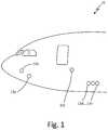
- FIG. 1is a diagram illustrating an aircraft that includes a plurality of probes.
- FIG. 2is a diagram of an aircraft probe that includes a heating element.
- FIG. 3is a diagram illustrating a heating element of an aircraft probe.
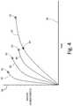
- FIG. 4is chart illustrating functions of a monitored characteristic of a plurality of probe heating elements over time.
- FIGS. 5A and 5Bare charts illustrating monitored current based on a low voltage for a heating element over time.
- FIG. 6is a chart illustrating a resonant frequency over time for a heating element of an aircraft probe.
- FIGS. 7A and 7Bare thermal images of an aircraft probe.
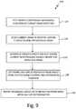
- FIG. 8is a flowchart illustrating a method of determining a remaining useful life of a probe based upon detected micro-fractures.
- FIG. 9is a flowchart illustrating a method of determining a remaining useful life of a probe based upon a monitored current draw over time by a heating element of a probe.
- FIG. 10is a flowchart illustrating a method of determining a remaining useful life of a probe based upon a determined capacitance of a heating element of a probe.
- FIG. 11is a flowchart illustrating a method of determining a remaining useful life of a probe based upon current leakage of a heating element of the probe.
- FIG. 12is a flowchart illustrating a method of determining a remaining useful life of a probe based upon a resonant frequency of a heating element of the probe.
- FIG. 13is a flowchart illustrating a method of determining a remaining useful life of a probe based upon thermal imaging of the probe.
- FIG. 14is a flowchart illustrating a method of determining a remaining useful life of a probe based upon an antenna response of a heater element of the probe.
- a system and method for determining the remaining useful life of a probeincludes monitoring characteristics of the probe over time.
- the probewhich may be an aircraft total-air-temperature (TAT) probe or any other probe, includes a resistive heating element, such as a heater wire, routed through the probe. Over time, as the heater wire ages, the heater wire may degrade, causing characteristics of the heater wire to change. These changing characteristics may be monitored and plotted over time, for example. The remaining useful life of the probe may then be determined and reported based upon the monitored characteristics.
- TATtotal-air-temperature
- FIG. 1is a diagram illustrating aircraft 10 that includes a plurality of probes 12 a - 12 n . While illustrated as a commercial aircraft, other vehicles, such as unmanned aerial vehicles, helicopters and ground vehicles may also include probes 12 a - 12 n configured to sense characteristics of the environment. Probes 12 a - 12 n may be any type of probe such as, but not limited to, pitot probes, TAT probes, angle-of-attack (AOA) probes and any other probes that may include a resistive heating element.
- AOAangle-of-attack
- FIG. 2illustrates aircraft probe 12 a that includes resistive heating element 14 . While illustrated in FIG. 2 as a TAT probe 12 a , aircraft probe 12 a may be any other type of probe 12 a - 12 n or sensing element. Probe 12 a is connected to receive control and power from control and interface circuit 16 . Control and interface circuit 16 may be implemented local to probe 12 a (e.g., implemented as a “smart probe”) or remote of probe 12 a . Control and interface circuit 16 may include, for example, a microcontroller, programmable logic device, application integrated circuit (ASIC), or any other digital and/or analog circuitry.
- ASICapplication integrated circuit
- Resistive heating element 14which may be a heater wire, for example, may receive power directly, or through control and interface circuit 16 , from aircraft power bus 18 to provide heating for probe 12 a .
- Power bus 18may be any direct current (DC) or alternating current (AC) aircraft power bus.
- resistive heating element 14may receive power from a 28 Volt DC power bus.
- An operational currentbased on the power received from power bus 18 , flows through resistive heating element 14 , which provides heating for probe 12 a .
- Control and interface circuit 16may also be connected to aircraft avionics 20 . Alternatively, control and interface circuit 16 may be implemented integral to aircraft avionics 20 . Control and interface circuit 16 may be configured to provide data to, and receive data from, aircraft avionics 20 .
- Current sensors 22 a and 22 bmay sense current flowing into, and out of, resistive heating element 14 at heating element input 26 a and heating element output 26 b , respectively.
- Current sensors 22 a and 22 bmay provide a signal indicative of the sensed current at the respective locations to control and interface circuit 16 .
- Temperature sensor 24may be positioned to sense a temperature of probe 12 a and provide the sensed temperature to control and interface circuit 16 . In other embodiments, a temperature may be estimated, for example, based upon sensed aircraft conditions and provided to control and interface circuit 16 from avionics 20 .
- avionics 20may determine a present altitude and/or airspeed of aircraft 10 and may estimate the temperature of probe 12 a based upon, among other items, the present altitude and/or airspeed.
- Current sensors 22 a and 22 bmay be any devices that sense current.
- current sensors 22 a and 22 bmay be non-contact current sensors such as, for example, a current transformer or Hall effect sensor.
- Thermal imager 28may be located integral to, or separate from, aircraft 10 .
- Thermal imager 28may be any device capable of receiving infrared radiation, for example, and providing an electrical output indicative of the received infrared radiation. While not illustrated as such, thermal imager 28 may be connected to communicate with control and interface circuit 16 and/or avionics 20 through a wired or wireless connection. This way, thermal images of probe 12 a may be obtained, analyzed and stored over time.
- Radio-frequency (RF) antenna 30is any antenna structure capable of emitting and/or receiving an RF signal.
- RF antenna 30may be configured to receive power and emit RF radiation that may be received by heating element 14 , for example.
- Heating element 14which may include a large loop of heater wire having dielectric properties, may act as an antenna, capable of emitting and/or receiving RF energy.
- RF antenna 30may be located integral to, or separate from, aircraft 10 .
- RF antenna 30may be connected to communicate with control and interface circuit 16 and/or avionics 20 through a wired or wireless connection (not shown). This way, control and interface circuit 16 may control RF antenna 30 to emit a plurality of RF signal frequencies, and/or may analyze a response of RF antenna 30 to an RF signal emitted by heater wire 14 , for example.
- resistive heating element 14may degrade, and eventually break down such that current may no longer flow through resistive heating element 14 to provide heating for probe 12 a .
- aircraft probe 12 amust be repaired or replaced.
- a TAT probemay be utilized, among other things, to determine a Mach number for the aircraft. The Mach number may be needed for takeoff and thus, the TAT probe may be required to be functional prior to taking off. If the TAT probe is malfunctioning, it must be replaced, which may cause undesirable flight delays. If the remaining useful life of the TAT probe is known, the TAT probe can be replaced between flights or at another convenient time for repair, preventing delays or other costs incurred due to an unexpected failure of the probe.
- FIG. 3is a diagram illustrating an embodiment of heating element 14 of aircraft probe 12 a .
- Heating element 14which is shown as a heater wire in the embodiment illustrated in FIG. 3 , includes lead wire 40 , heater element 42 , insulation 44 and sheath casing 46 .
- Sheath casing 46may be a metallic sheath and thus, there may be a measurable capacitance between sheath casing 46 and lead wire 40 .
- Ring oscillator 48may be any oscillator circuit in which a capacitance may be utilized to drive an output frequency, for example.
- Capacitive measurement circuit 50is any circuit capable of providing a value to control and interface circuit 16 , for example, that allows control and interface circuit 16 to determine the capacitance between sheath casing 46 and lead wire 40 .
- capacitive measurement circuit 50may be a resistor-capacitor (RC) or resistor-inductor-capacitor (RLC) circuit connected such that the capacitor for the RC or RLC circuit is the capacitance between lead wire 40 and metallic sheath 46 .
- ring oscillator 48 and capacitive measurement circuit 50may be the same circuit.
- heating element 14may be oxidized and the dielectric material properties of heating element 14 may change. This may lead to certain characteristics of heating element 14 such as resistance and the capacitance between wire 40 and metallic sheath 46 , among other characteristics, to change over time.
- FIG. 4illustrates functions 60 of a monitored characteristic over the life of several resistive heating elements 14 of several respective probes 12 a - 12 n until breakdown 62 .
- a heater wiremay degrade as the heater wire ages. This degradation may cause changes in characteristics of heater wire 14 such as resistance and capacitance.
- the current drawn through resistive heating element 14may increase monotonically over the life of heating element 14 . This increase is not linear, but rather follows exponential function 60 , with a point 64 of interest. Point 64 may be the point on function 60 , for example, at which the slope transitions from greater than 1 to less than 1. While the maximum normalized characteristic and life of each resistive heating element 14 at breakdown 62 may fluctuate, exponential function 60 of the heater characteristic over the life of each resistive heating element 14 remains similar.
- Functions 60 shown in FIG. 4may be obtained, for example, through testing of probes 12 a - 12 n .
- function 60may be determined through the testing of probes 12 a - 12 n .
- Currentmay be cycled, for example, until heating element 14 of a respective test probe 12 a - 12 n breaks down.
- a characteristic of heating element 14may be monitored each test cycle and plotted over time until breakdown 62 . The plots of the characteristic may then be utilized to determine function 60 .
- Function 60may then be utilized during normal operation of a probe 12 a - 12 n to determine, for example, a half-life estimate of heating element 14 .
- other algorithmsmay be utilized to determine the remaining useful life of heating element 14 based upon the plotted data.
- currentmay be sampled using current sensor 22 a or 22 b at any time during flight and provided to control and interface circuit 16 several times each flight. This sampled current may be stored in a memory of control and interface circuit 16 , for example, or some other memory or storage device. Because current is directly affected by temperature, a temperature may also be sensed using temperature sensor 24 and stored along with a respective sensed current so that the current may be normalized with respect to temperature. Alternatively, a temperature may be estimated using data from avionics 20 , for example. Control and interface circuit 16 may utilize the sensed or estimated temperature to directly normalize the current prior to storage, or may store the two values for later normalization.
- Function 60may be used in conjunction with the stored normalized current to determine the half-life estimate of heating element 14 .
- the stored normalized currentmay be plotted by control and interface circuit 16 such that a present slope of the plot may be determined. This present slope may be utilized, for example, to detect point 64 by detecting that the slope of the plot has transitioned from greater than 1 to less than 1, or any other point on function 60 . Once point 64 is detected, for example, the half-life of heating element 14 may be determined.
- FIGS. 5A and 5Bare charts illustrating monitored current based upon a normal operating voltage and a low voltage for heating element 14 over time.
- FIG. 5Aillustrates both a current draw 70 for an operating voltage and current draw 72 for a low voltage.
- FIG. 5Bshows a zoomed in view of current draw 72 for a low voltage.
- the operating voltagemay be, for example, 28 Volts while the low voltage may be, for example, 0.1 Volts.
- heating element 14At the end of the life of heating element 14 , thermal fatigue causes heater wire 40 to fracture and gradually become electrically open, which increases the resistance of heating element 14 .
- electron tunnelingis the main mechanism for electrical current conduction.
- Arcing that occurs at 0.1 Voltsmay indicate a micro fracture with a gap on the order of 1 nanometer (nm), while arcing that occurs at 28 Volts may correspond to an approximately 0.3 micrometer (um) gap.
- micro fracturesmay be detected by monitoring a current response using a low voltage prior to failure of heating element 14 .
- the current drawn during normal operation(e.g., receiving 28 Volts from power bus 18 ) remains substantially greater than zero over all cycles.
- the current drawn with 0.1 Voltsbegins to degrade to, and remain at, zero while the current drawn during normal operation continues to be substantially greater than zero.
- This degradation of current to zero at low voltageindicates that a micro fracture is present in heating element 14 .
- This micro fracturemay eventually grow in size, ultimately causing failure of probe 12 a .
- failure of probe 12 amay be predicted such that a remaining useful life of heating element 14 , and in turn, probe 12 a , may be determined.
- the amount of remaining useful life of probe 12 a following detection of a micro fracturemay be determined, for example, through testing of probes 12 a - 12 n .
- Currentmay be cycled, for example, until heating element 14 of a respective test probe 12 a - 12 n breaks down.
- a low voltagemay be provided to test probes 12 a - 12 n . While the low voltage is supplied, a current may be sensed and stored. This way, the cycle at which a micro fracture on the order of 1 nm is detected may be determined.
- a percentage of life after detection of the micro fracturemay be determined.
- a low voltagemay be provided, for example, by control and interface circuit 16 between flights of aircraft 10 , or at any other time during which heating element 14 is not receiving an operational voltage.
- Current sensor 22 a or 22 bmay be utilized by control and interface circuit 16 to obtain a sensed current while providing the low voltage. Upon detection of the sensed current going to zero at low voltage, a remaining useful life may be determined based upon the percentage of life determined during testing of the probes 12 a - 12 n.
- FIG. 6is a chart illustrating a resonant frequency over time for heating element 14 of aircraft probe 12 a .
- FIG. 6also illustrates a curve 80 fit to the resonant frequency plot over time.
- a capacitanceexists between metallic sheath 46 and lead wire 40 .
- changes to heating element 14happen due to hot and cold cycles in addition to varying environmental conditions such as temperature, pressure, humidity, environmental gases, and aerosols, among others. These conditions, in addition to the temperature cycling of probe 12 a , cause the probe heater sealing to be compromised, which may lead to various materials leaking into insulation 44 and heater element 42 .
- Wire 40may be oxidized and dielectric material properties may change, leading to a change in capacitance and resistance of heating element 14 . Because the capacitance changes, the resonant frequency also changes.
- the capacitance between metallic sheath 46 and lead wire 40may be swept with frequencies ranging from 1 kilohertz (KHz) to 100 megahertz (MHz) by control and interface circuit 16 , for example, through capacitive measurement circuit 50 .
- the peak frequency response and bandwidthmay be identified by control and interface circuit 16 .
- This peak frequency responsemay be monitored and stored over time and plotted as shown in FIG. 6 .
- a function 80 obtained during testing of probes 12 a - 12 nmay then be utilized in conjunction with the stored and plotted resonant frequency to determine a remaining useful life of probe 12 a .
- the slope of the plotted resonancetransitions from greater than ⁇ 1 to less than ⁇ 1, or when the slope transitions from a negative value to a positive value, as seen in FIG. 6 . Determination of a present point on function 80 allows control and interface circuit 16 to determine a remaining useful life of probe 12 a.
- algorithms that separate data indicative of a healthy probe and data indicative of an increasingly unhealthy probemay be executed utilizing various signal processing techniques to determine the remaining useful life of heating element 14 .
- various signal processing techniquesFor example, time-frequency analysis, machine learning, index theory and other signal processing techniques may be utilized to determine remaining useful life of heating element 14 based upon the monitored resonant frequency.
- ring oscillator 48may be utilized with probe 12 a as the driving element of the output frequency of ring oscillator 48 .
- Ring oscillator 48or other oscillator circuit, has an output frequency dependent upon the structure of the circuit and the input voltage to the circuit. By controlling the input voltage, the output frequency of ring oscillator 48 can be made dependent solely upon the capacitance between metallic sheath 46 and lead wire 40 . As this capacitance changes as heating element 14 degrades, so does the output frequency of ring oscillator 48 . The changing output frequency may be stored and plotted over time to determine a remaining useful life of probe 12 a .
- testing of probes 12 a - 12 nmay result in a function of the output frequency similar to that shown in FIG. 4 or 6 .
- This functionin conjunction with the stored and plotted output frequency, may be utilized to determine the remaining useful life of probe 12 a during normal operation.
- RF antenna 30may be controlled to sweep a wide range of frequencies.
- control and interface circuit 16may provide AC power to antenna 30 at varying frequencies to facilitate emission of RF radiation at a plurality of frequencies from antenna 30 .
- the S12 parameter for heating element 14which is a measure of the power received at heating element 14 from the RF emission of antenna 30 , may be determined and monitored by control and interface circuit 16 .
- This antenna response of heating element 14may be analyzed by control and interface circuit 16 to determine, for example, a resonant frequency response of heating element 14 .
- the antenna properties of heating element 14may be dependent upon, among other things, length and shape of heating element 14 , and dielectric properties of heating element 14 . These dielectric properties may include, for example, permittivity, permeability, homogeneity and thickness, among others. As the wire ages and degrades, the dielectric properties of heating element 14 may change, which may lead to a change in the resonant frequency of heating element 14 .
- the determined resonant frequencymay be monitored and plotted over time by control and interface circuit 16 .
- Testing of probes 12 a - 12 nmay be utilized to determine a function at which the resonant frequency changes over time. This function may substantially follow those shown in FIG. 4 or 6 , for example. This function may then be utilized to determine, for example, a half-life of heating element 14 base upon the determined resonant frequency during normal operation of probe 12 a .
- an algorithmmay be executed using signal processing techniques to determine the remaining useful life of probe 12 a based upon the resonant frequency changes over time.
- control and interface circuit 16may provide AC power to heating element 14 at varying frequencies to facilitate emission of RF radiation at a plurality of frequencies from heating element 14 . Control and interface circuit 16 may then monitor the S12 parameter of RF antenna 30 to determine a resonant frequency, which may be monitored and analyzed over time to determine a half-life of heating element 14 .
- FIGS. 7A and 7Bare representatives of thermal images of aircraft probe 12 a . These images may be obtained, for example, using thermal imager 28 ( FIG. 2 ).
- FIG. 7Aillustrates probe 12 a at a beginning of its lifetime
- FIG. 7Billustrates probe 12 a at a later point in its lifetime.
- the thermal imagesmay be utilized, for example, to determine a thermal response of heating element 14 over time. Points of interest 90 a and 92 a show a thermal response of heating element 14 at the beginning of life of heating element 14 , while points of interest 90 b and 92 b show a thermal response of heating element 14 at a later point in life.
- any number of thermal images at any angle with respect to probe 12 amay be obtained by imager 28 .
- Other points of interest for heating element 14may also be monitored separately, or in conjunction with, points 90 a , 90 b , 92 a and 92 b to determine the thermal response of heating element 14 .
- the temperature at points 90 b and 92 b of heating element 14has increased from the temperature at points 90 a and 92 a shown in FIG. 7A .
- This increasemay be due to changes in heating element caused by degradation of heating element 14 over time.
- the increase in temperature over timemay substantially follow an exponential function similar to those illustrated in FIG. 4 .
- the thermal response of heating element 14e.g., the increase in temperature seen at points 90 b and 92 b
- An exponential function determined during testing of probes 12 a - 12 nmay then be used in conjunction with the stored and plotted thermal response to determine a half-life of heating element 14 .
- FIG. 8is a flowchart illustrating method 100 of determining a remaining useful life of probe 12 a based upon detected micro-fractures.
- a low voltageis provided to heating element 14 of probe 12 a .
- This low voltagemay be provided at any time, such as right after power down of probe 12 a .
- the low voltagemay be approximately 0.1 V, which may be low enough to detect micro fractures on the order of 1 nm.
- a step 104while the low voltage is being supplied to heating element 14 , current is sensed by one of current sensors 22 a and 22 b .
- the sensed currentmay be provided to, and stored by, control and interface circuit 16 .
- the process in steps 102 and 104is repeated over time, and the sensed current is monitored by control and interface circuit 16 at step 106 .
- micro fractures in heating element 14are detected based upon the monitored current. For example, if the monitored current has dropped to zero, as illustrated in FIG. 5B , a micro fracture is detected by control and interface circuit 16 .
- the remaining useful life of heating element 14may be estimated. This estimation may be based upon testing of heating elements 14 , for example. Probes 12 a - 12 n may be tested to determine an average remaining useful life of heating element 14 following detection of a micro fracture of approximately 1 nm.
- the remaining useful life of resistive heating element 14may be reported at step 110 .
- This reportmay be made to the cockpit through avionics 20 , or to some other computer system. By reporting the remaining useful life, probes 12 a - 12 n may be replaced prior to breaking down and thus, unnecessary flight delays may be avoided.
- FIG. 9is a flowchart illustrating method 120 of determining a remaining useful life of a probe 12 a - 12 n based upon monitored current drawn over time by a respective heating element 14 .
- an exponential function for a respective probe 12 a - 12 nmay be determined, for example, through testing of similar probes 12 a - 12 n .
- the test probesmay have a test current provided to a respective resistive heating element 14 during a plurality of test cycles. The current may be sensed at common points during each of the plurality of test cycles and the sensed currents may then be plotted and functions 60 may be determined as shown in FIG. 4 for the respective resistive heating elements 14 .
- This exponential functionmay then be used for all similar probes 12 a - 12 n during normal probe operation in order to determine a half-life of a respective resistive heating element 14 , for example.
- resistive heating element 14may fluctuate based upon the operating point of probe 12 a - 12 n . Therefore, it may be desirable at step 124 to sense the operational current at a similar point of operation of heating element 14 . For example, upon initial power-on of resistive heating element 14 , the current may rise to a peak current. As resistive heating element 14 increases in temperature, the current through resistive heating element 14 will decrease to a lower, steady-state current. Thus, current may be sampled and stored consistently at the peak value, at the steady-state value, or at some other expected value, for example.
- Temperaturemay also be sensed and provided to control and interface circuit 16 using temperature sensor 24 .
- control and interface circuit 16may normalize the sensed current using the sensed temperature. Steps 124 and 126 may be repeated and the normalized sensed current may be plotted over several flights, for example, to establish a curve fit. The curve fit may substantially follow the exponential function determined, for example, at step 122 .
- the present slope of the sensed currentmay be determined based upon the exponential function. This slope may then be utilized to determine the half-life of resistive heating element 14 . By knowing the half-life of resistive heating element 14 , the remaining useful life of resistive heating element 14 may be determined by control and interface circuit 16 , for example.
- the remaining useful life of resistive heating element 14may be reported at step 130 .
- This reportmay be made to the cockpit through avionics 20 , or to some other computer system. By reporting the remaining useful life, probes 12 a - 12 n may be replaced prior to breaking down and thus, unnecessary flight delays may be avoided.
- FIG. 10is a flowchart illustrating method 140 of determining a remaining useful life of probes 12 a - 12 n based upon a determined capacitance of a respective heating element 14 .
- an exponential function for a respective probe 12 a - 12 nmay be determined, for example, through testing of similar test probes.
- the test probesmay have a test current provided to a respective resistive heating element 14 during a plurality of test cycles to simulate the life of the respective probe 12 a - 12 n .
- the currentmay be cycled until failure of each respective probe 12 a - 12 n .
- the capacitance of each respective heating element 14may be determined during each cycle, for example.
- An exponential functionsuch as those shown in FIG. 4 , may be determined based upon the determined capacitances. This exponential function may then be used for all similar probes 12 a - 12 n during normal probe operation in order to determine a half-life of a respective resistive heating element 14 , for example.
- capacitive measurement circuit 50may be utilized to determine a capacitance between metallic sheath 46 and lead wire 40 .
- the capacitance and capacitance measurement circuit 50may be directly affected by temperature.
- temperaturemay be sensed and provided to control and interface circuit 16 using temperature sensor 24 .
- Steps 144 and 146may be repeated throughout the life of probe 12 a and control and interface circuit 16 may normalize the determined capacitance using the sensed temperature and may plot the normalized determined capacitance over several flights, for example, to establish a curve fit.
- the curve fitmay substantially follow the exponential function determined, for example, at step 142 .
- the present slope of the determined capacitancemay be determined based upon the exponential function. This slope may then be utilized to determine the half-life of resistive heating element 14 . By knowing the half-life of resistive heating element 14 , the remaining useful life of resistive heating element 14 may be determined by control and interface circuit 16 , for example.
- the remaining useful life of resistive heating element 14may be reported at step 150 .
- This reportmay be made to the cockpit through avionics 20 , or to some other computer system. By reporting the remaining useful life, probes 12 a - 12 n may be replaced prior to breaking down and thus, unnecessary flight delays may be avoided.
- FIG. 11is a flowchart illustrating method 160 of determining a remaining useful life of probes 12 a - 12 n based upon a measured leakage current for a respective heating element 14 .
- an exponential function for a respective probe 12 a - 12 nmay be determined, for example, through testing of similar probes 12 a - 12 n .
- the test probesmay have a test current provided to a respective resistive heating element 14 during a plurality of test cycles to simulate the life of the respective probe 12 a - 12 n .
- Currentmay be sampled by both current sensors 22 a and 22 b and provided to control and interface circuit 16 .
- the current from current sensor 22 bmay be subtracted from the current from current sensor 22 a to determine a leakage current of resistive heating element 14 .
- the currentmay be cycled until failure of each respective probe 12 a - 12 n at which time the exponential function, similar to those illustrated in FIG. 4 , may be determined.
- leakage current from resistive heating element 14may be determined based upon sensed current from both current sensors 22 a and 22 b .
- Current through resistive heating element 14may fluctuate based upon the operating point of probe 12 a - 12 n . Therefore, it may be desirable to determine the leakage current at a similar point of operation of heating element 14 each time the current is sensed and stored. For example, upon initial power-on of resistive heating element 14 , the current may rise to a peak current. As resistive heating element 14 increases in temperature, the current through resistive heating element 14 will decrease to a lower, steady-state current. Thus, current may be sampled and stored consistently at the peak value, at the steady-state value, or at some other expected value, for example.
- Temperaturemay also be sensed and provided to control and interface circuit 16 using temperature sensor 24 .
- control and interface circuit 16may normalize the determined leakage current using the sensed temperature. Steps 164 and 166 may be repeated and control and interface circuit 16 may plot the normalized leakage current over several flights, for example, to establish a curve fit. The curve fit may substantially follow the exponential function determined, for example, at step 162 .
- the present slope of the determined leakage currentmay be determined based upon the exponential function. This slope may then be utilized to determine the half-life of resistive heating element 14 . By knowing the half-life of resistive heating element 14 , the remaining useful life of resistive heating element 14 may be determined by control and interface circuit 16 , for example.
- the remaining useful life of resistive heating element 14may be reported at step 170 .
- This reportmay be made to the cockpit through avionics 20 , or to some other computer system. By reporting the remaining useful life, probes 12 a - 12 n may be replaced prior to breaking down and thus, unnecessary flight delays may be avoided.
- FIG. 12is a flowchart illustrating method 180 of determining a remaining useful life of probes 12 a - 12 n based upon a resonant frequency of a respective heating element 14 .
- an exponential function for a respective probe 12 a - 12 nmay be determined, for example, through testing of similar test probes.
- the exponential functionmay be similar to that shown in FIG. 6 .
- the test probesmay have a test current provided to a respective resistive heating element 14 during a plurality of test cycles to simulate the life of the respective probe 12 a - 12 n . The current may be cycled until failure of each respective probe 12 a - 12 n .
- the resonant frequency based on the capacitance of each respective heating element 14may be determined during each cycle, for example, using capacitive measurement circuit 50 .
- an output frequency of oscillator circuit 48 driven by the capacitance of heating element 14may be determined during each cycle.
- An exponential functionsuch as that shown in FIG. 4 or FIG. 6 , may be determined based upon the determined resonant or output frequency. This exponential function may then be used for all similar probes 12 a - 12 n during normal probe operation in order to determine a half-life of a respective resistive heating element 14 , for example.
- capacitive measurement circuit 50may be used to determine a resonant frequency of heating element 14 or ring oscillator circuit 48 may be utilized to determine an output frequency of ring oscillator 48 driven by the capacitance of heating element 14 .
- temperaturemay also be sensed and provided to control and interface circuit 16 using temperature sensor 24 .
- Control and interface circuit 16may normalize the determined resonant frequency using the sensed temperature. Steps 184 and 186 may be repeated and control and interface circuit 16 may plot the normalized resonant or output frequency over several flights, for example, to establish a curve fit.
- both the capacitance and ring oscillator circuit 48may be directly affected by temperature.
- the curve fitmay substantially follow the exponential function determined, for example, at step 182 .
- the present slope of the determined resonancemay be determined based upon the exponential function. This slope may then be utilized to determine the half-life of resistive heating element 14 . By knowing the half-life of resistive heating element 14 , the remaining useful life of resistive heating element 14 may be determined by control and interface circuit 16 , for example.
- the remaining useful life of resistive heating element 14may be reported at step 190 .
- This reportmay be made to the cockpit through avionics 20 , or to some other computer system. By reporting the remaining useful life, probes 12 a - 12 n may be replaced prior to breaking down and thus, unnecessary flight delays may be avoided.
- FIG. 13is a flowchart illustrating method 200 of determining a remaining useful life of probes 12 a - 12 n based upon thermal imaging of a respective heating element 14 .
- an exponential function for a respective probe 12 a - 12 nmay be determined, for example, through testing of similar test probes.
- the exponential functionmay be similar to that shown in FIG. 4 .
- the test probesmay have a test current provided to a respective resistive heating element 14 during a plurality of test cycles to simulate the life of the respective probe 12 a - 12 n .
- the currentmay be cycled until failure of each respective probe 12 a - 12 n .
- Thermal imagesmay be taken by thermal imager 28 for each respective heating element 14 each cycle, for example.
- An exponential functionsuch as that shown in FIG. 4 , may be determined based upon the thermal images. This exponential function may then be used for all similar probes 12 a - 12 n during normal probe operation in order to determine a half-life of a respective resistive heating element 14 , for example.
- thermal imager 28may be utilized to obtain thermal images of heating element 14 .
- temperaturemay also be sensed and provided to control and interface circuit 16 using temperature sensor 24 .
- Control and interface circuit 16may normalize the thermal data using the sensed temperature.
- Control and interface circuit 16may also normalize the thermal image data to compensate for probe shape and surface emissivity, for example.
- Steps 204 and 206may be repeated and control and interface circuit 16 may plot the normalized thermal data over several flights, for example, to establish a curve fit.
- the curve fitmay substantially follow the exponential function determined, for example, at step 202 .
- the present slope of the determined thermal databe determined based upon the exponential function. This slope may then be utilized to determine the half-life of resistive heating element 14 . By knowing the half-life of resistive heating element 14 , the remaining useful life of resistive heating element 14 may be determined by control and interface circuit 16 , for example.
- the remaining useful life of resistive heating element 14may be reported at step 210 .
- This reportmay be made to the cockpit through avionics 20 , or to some other computer system. By reporting the remaining useful life, probes 12 a - 12 n may be replaced prior to breaking down and thus, unnecessary flight delays may be avoided.
- FIG. 14is a flowchart illustrating method 220 of determining a remaining useful life of probes 12 a - 12 n based upon an antenna response of a respective heating element 14 .
- an exponential function for a respective probe 12 a - 12 nmay be determined, for example, through testing of similar test probes.
- the exponential functionmay be similar to that shown in FIG. 4 .
- the test probesmay have a test current provided to a respective resistive heating element 14 during a plurality of test cycles to simulate the life of the respective probe 12 a - 12 n . The current may be cycled until failure of each respective probe 12 a - 12 n .
- RF antenna 30may be utilized during each cycle, for example, to sweep frequencies of RF radiation to heating element 14 .
- An exponential functionsuch as that shown in FIG. 4 , may be determined based upon a detected resonant frequency of heater element 14 in response to the RF radiation from antenna 30 over each cycle. This exponential function may then be used for all similar probes 12 a - 12 n during normal probe operation in order to determine a half-life of a respective resistive heating element 14 , for example.
- RF antenna 30may be utilized to provide RF radiation to heating element 14 .
- control and interface circuit 16may monitor the S12 parameter of heating element 14 to determine a resonant frequency response of heating element 14 to the RF radiation.
- heating element 14may be energized to provide RF radiation to antenna 30 and control and interface circuit 16 may monitor the S12 parameter of antenna 30 to determine a resonant frequency response of antenna 30 .
- Steps 224 and 226may be repeated and control and interface circuit 16 may plot the resonant frequency response over several flights, for example, to establish a curve fit.
- the curve fitmay substantially follow the exponential function determined, for example, at step 222 .
- the present slope of the determined RF responsemay be determined based upon the exponential function. This slope may then be utilized to determine the half-life of resistive heating element 14 . By knowing the half-life of resistive heating element 14 , the remaining useful life of resistive heating element 14 may be determined by control and interface circuit 16 , for example.
- the RF responsemay be normalized to account for, among other things, temperature. This may be accomplished using data from temperature sensor 24 , or an estimate temperature based upon data from avionics 20 , for example.
- the remaining useful life of resistive heating element 14may be reported at step 230 .
- This reportmay be made to the cockpit through avionics 20 , or to some other computer system. By reporting the remaining useful life, probes 12 a - 12 n may be replaced prior to breaking down and thus, unnecessary flight delays may be avoided.
- a system for an aircraftincludes a probe, an antenna and a control circuit.
- the probeincludes a heater comprising a resistive heating element routed through the probe.
- An operational voltageis provided to the resistive heating element to provide heating for the probe.
- the control circuitis configured to determine an antenna interaction between the resistive heating element and the antenna and determine a remaining useful life of the probe based on the antenna interaction over time.
- the system of the preceding paragraphcan optionally include, additionally and/or alternatively, any one or more of the following features, configurations and/or additional components:
- RFradio-frequency
- the RF antennais configured to provide a radio-frequency (RF) signal to the probe
- the control circuitis configured to determine the response of the resistive heating element to the RF signal as the antenna interaction.
- the RF signalcomprises a plurality of signal frequencies
- the control circuitis configured to determine a resonant frequency from the resistive heating element in response to the plurality of signal frequencies.
- control circuitis configured to determine the resonant frequency from the resistive heating element over a plurality of flights of the aircraft.
- control circuitis configured to plot the resonant frequency over the plurality of flights and determine a half-life estimate of the resistive heating element based on the plot.
- control circuitis configured to provide a heater signal having a plurality of frequencies to the resistive heating element, and wherein the resistive heating element generates a radio-frequency (RF) signal based on the heater signal, and wherein the control circuit is configured to determine the response of the RF antenna to the RF signal.
- RFradio-frequency
- a further embodiment of any of the foregoing systemsfurther comprising a temperature sensor configured to sense a temperature of the probe and provide the sensed temperature to the control circuit, wherein the control circuit is configured to normalize the antenna interaction based on the sensed temperature.
- control circuitis configured to normalize the antenna interaction based on an estimate temperature of the heater.
- a method for determining a remaining useful life of a probeincludes providing an operational voltage to a resistive heating element of the aircraft probe during a plurality of flights of an aircraft to provide heat for the probe; providing, by a radio-frequency (RF) antenna, a radio-frequency (RF) signal to the probe; determining, by a control circuit, an antenna response of the resistive heating element of the aircraft probe during the plurality of flights; and determining the remaining useful life based upon the antenna response over time.
- RFradio-frequency
- RFradio-frequency
- the method of the preceding paragraphcan optionally include, additionally and/or alternatively, any one or more of the following features, configurations and/or additional components:
- a further embodiment of the foregoing method, wherein providing, by the RF antenna, the RF signal to the probeincludes providing the RF signal at plurality of signal frequencies.
- determining, by the control circuit, the antenna response of the resistive heating element of the aircraft probe during the plurality of flightsincludes determining a resonant frequency from the resistive heating element in response to the plurality of signal frequencies.
- determining the remaining useful life based upon the antenna response over timeincludes plotting the resonant frequency over the plurality of flights; and determining a half-life estimate of the resistive heating element based on the plot.
- a probe systemconfigured to receive a radio-frequency (RF) signal from a radio-frequency (RF) antenna includes a heater and a control circuit.
- the heaterincludes a resistive heating element routed through the probe system.
- An operational voltageis provided to the resistive heating element to provide heating for the probe system and the resistive heating element has an element capacitance.
- the control circuitis configured to determine an antenna response of the resistive heating element and determine a remaining useful life of the probe system based on the antenna response over time.
- the probe system of the preceding paragraphcan optionally include, additionally and/or alternatively, any one or more of the following features, configurations and/or additional components:
- the RF signalcomprises a plurality of signal frequencies
- the control circuitis configured to determine a resonant frequency from the resistive heating element in response to the plurality of signal frequencies.
- control circuitis configured to determine the resonant frequency from the resistive heating element over a plurality of flights of the aircraft.
- control circuitis configured to plot the resonant frequency over the plurality of flights and determine a half-life estimate of the resistive heating element based on the plot.
- a further embodiment of any of the foregoing probe systemsfurther comprising a temperature sensor configured to sense a temperature of the probe system and provide the sensed temperature to the control circuit, wherein the control circuit is configured to normalize the antenna response based on the sensed temperature.
- control circuitis configured to normalize the antenna response based on an estimated temperature of the heater.
Landscapes
- Physics & Mathematics (AREA)
- General Physics & Mathematics (AREA)
- Engineering & Computer Science (AREA)
- Aviation & Aerospace Engineering (AREA)
- Chemical & Material Sciences (AREA)
- Analytical Chemistry (AREA)
- General Health & Medical Sciences (AREA)
- Electrochemistry (AREA)
- Health & Medical Sciences (AREA)
- Life Sciences & Earth Sciences (AREA)
- Pathology (AREA)
- Biochemistry (AREA)
- Chemical Kinetics & Catalysis (AREA)
- Immunology (AREA)
- Electromagnetism (AREA)
- General Engineering & Computer Science (AREA)
- Spectroscopy & Molecular Physics (AREA)
- Investigating Or Analyzing Materials Using Thermal Means (AREA)
- Control Of Resistance Heating (AREA)
- Testing Electric Properties And Detecting Electric Faults (AREA)
Abstract
Description
Claims (8)
Priority Applications (3)
| Application Number | Priority Date | Filing Date | Title |
|---|---|---|---|
| US15/468,872US10895592B2 (en) | 2017-03-24 | 2017-03-24 | Probe heater remaining useful life determination |
| EP18153834.9AEP3379265B1 (en) | 2017-03-24 | 2018-01-29 | Probe heater remaining useful life determination |
| EP19203208.4AEP3614152B1 (en) | 2017-03-24 | 2018-01-29 | Probe heater remaining useful life determination |
Applications Claiming Priority (1)
| Application Number | Priority Date | Filing Date | Title |
|---|---|---|---|
| US15/468,872US10895592B2 (en) | 2017-03-24 | 2017-03-24 | Probe heater remaining useful life determination |
Publications (2)
| Publication Number | Publication Date |
|---|---|
| US20180275183A1 US20180275183A1 (en) | 2018-09-27 |
| US10895592B2true US10895592B2 (en) | 2021-01-19 |
Family
ID=61094241
Family Applications (1)
| Application Number | Title | Priority Date | Filing Date |
|---|---|---|---|
| US15/468,872Active2038-07-10US10895592B2 (en) | 2017-03-24 | 2017-03-24 | Probe heater remaining useful life determination |
Country Status (2)
| Country | Link |
|---|---|
| US (1) | US10895592B2 (en) |
| EP (2) | EP3379265B1 (en) |
Cited By (3)
| Publication number | Priority date | Publication date | Assignee | Title |
|---|---|---|---|---|
| US20200379027A1 (en)* | 2019-05-29 | 2020-12-03 | Rosemount Aerospace Inc. | Differential leakage current measurement for heater health monitoring |
| US11472562B2 (en) | 2019-06-14 | 2022-10-18 | Rosemount Aerospace Inc. | Health monitoring of an electrical heater of an air data probe |
| US12146794B2 (en) | 2021-05-17 | 2024-11-19 | Rosemount Aerospace Inc. | Infrared inspection system for heaters comprised of positive temperature coefficient resistors |
Families Citing this family (16)
| Publication number | Priority date | Publication date | Assignee | Title |
|---|---|---|---|---|
| US11060992B2 (en) | 2017-03-24 | 2021-07-13 | Rosemount Aerospace Inc. | Probe heater remaining useful life determination |
| US10914777B2 (en) | 2017-03-24 | 2021-02-09 | Rosemount Aerospace Inc. | Probe heater remaining useful life determination |
| US10895592B2 (en) | 2017-03-24 | 2021-01-19 | Rosemount Aerospace Inc. | Probe heater remaining useful life determination |
| US10962580B2 (en) | 2018-12-14 | 2021-03-30 | Rosemount Aerospace Inc. | Electric arc detection for probe heater PHM and prediction of remaining useful life |
| US11061080B2 (en) | 2018-12-14 | 2021-07-13 | Rosemount Aerospace Inc. | Real time operational leakage current measurement for probe heater PHM and prediction of remaining useful life |
| US11930563B2 (en) | 2019-09-16 | 2024-03-12 | Rosemount Aerospace Inc. | Monitoring and extending heater life through power supply polarity switching |
| US11293995B2 (en) | 2020-03-23 | 2022-04-05 | Rosemount Aerospace Inc. | Differential leakage current measurement for heater health monitoring |
| US11630140B2 (en)* | 2020-04-22 | 2023-04-18 | Rosemount Aerospace Inc. | Prognostic health monitoring for heater |
| US11982721B2 (en) | 2021-01-08 | 2024-05-14 | Rosemount Aerospace Inc. | Detecting leakage currents in a powered electrical system |
| US11549390B2 (en)* | 2021-01-09 | 2023-01-10 | Rosemount Aerospace Inc. | Health-monitoring system for determining rotation frequency of a shaft |
| US11914003B2 (en) | 2021-03-30 | 2024-02-27 | Rosemount Aerospace Inc. | Predicting failure and/or estimating remaining useful life of an air-data-probe heater |
| US11913977B2 (en)* | 2021-05-17 | 2024-02-27 | Rosemount Aerospace Inc. | Positive temperature coefficient resistor heater assembly health monitoring |
| US11867746B2 (en) | 2021-09-14 | 2024-01-09 | Hamilton Sundstrand Corporation | Failure detection system for integrated circuit components |
| US12392796B2 (en)* | 2022-02-07 | 2025-08-19 | Rosemount Aerospace Inc. | Dynamic multi-stage air data probe prognostics health monitoring system |
| US20230252831A1 (en)* | 2022-02-07 | 2023-08-10 | Rosemount Aerospace Inc. | Dynamic multi-stage air data probe prognostics health monitoring management |
| US12420946B2 (en) | 2022-02-07 | 2025-09-23 | Rosemount Aerospace Inc. | Dynamic air data probe prognostics health monitoring coordinator |
Citations (150)
| Publication number | Priority date | Publication date | Assignee | Title |
|---|---|---|---|---|
| GB809608A (en) | 1955-04-22 | 1959-02-25 | Curtiss Wright Corp | Improved aircraft static pressure simulating system |
| GB884415A (en) | 1958-11-10 | 1961-12-13 | Kyowa Hakko Kogyo Kk | Method for producing l-pyrrolidonecarboxylic acid and its salts |
| US3798652A (en) | 1972-09-11 | 1974-03-19 | Gen Electric | Pitot tube dielectric antenna system |
| US4207566A (en) | 1978-05-05 | 1980-06-10 | American Aerospace Controls, Inc. | DC Current level detector for monitoring a pitot tube heater and associated method |
| US4267721A (en) | 1979-11-09 | 1981-05-19 | Timeter Instrument Corp. | Respiratory analyzer |
| US4506259A (en) | 1981-11-24 | 1985-03-19 | Raychem Corporation | Digital fault monitor for conductive heaters |
| US4698583A (en) | 1985-03-26 | 1987-10-06 | Raychem Corporation | Method of monitoring a heater for faults |
| WO1990011532A1 (en) | 1989-03-28 | 1990-10-04 | Raychem Limited | Monitoring electric cables |
| US5130652A (en) | 1988-11-30 | 1992-07-14 | Eddio Corporation | AC magnetic flux leakage flaw detecting apparatus for detecting flaws in flat surfaces with rotating leakage detection element |
| CA1311028C (en) | 1988-05-20 | 1992-12-01 | Westinghouse Electric Corporation | Instrumentation and monitoring systems employing differential temperature |
| US5216226A (en) | 1991-03-04 | 1993-06-01 | Mitsubishi Denki Kabushiki Kaisha | Apparatus for preventing and predicting deterioration of insulation in an electric equipment |
| US5218294A (en) | 1991-01-22 | 1993-06-08 | Advanced Test Technologies Inc. | Contactless test method for testing printed circuit boards |
| US5464965A (en) | 1993-04-20 | 1995-11-07 | Honeywell Inc. | Apparatus for controlling temperature of an element having a temperature variable resistance |
| WO1998016837A1 (en) | 1996-10-16 | 1998-04-23 | Rosemount Aerospace Inc. | Heated air data probe |
| US5767781A (en) | 1995-06-15 | 1998-06-16 | Applied Materials, Inc. | Method for detection of failed heater in a daisy chain connection |
| US5883512A (en) | 1995-12-14 | 1999-03-16 | Siemens Aktiengesellschaft | Checking heat exchanger tubes with an eddy-current integrity test |
| WO1999043066A1 (en) | 1998-02-19 | 1999-08-26 | Square D Company | Zone arc fault detection |
| US6070475A (en) | 1997-10-15 | 2000-06-06 | Rosemont Aerospace Inc. | Air data probe with heater means within wall |
| US6107661A (en) | 1995-09-29 | 2000-08-22 | Nippondenso Co., Ltd. | Semiconductor device and method of manufacturing same |
| US6151560A (en) | 1995-03-27 | 2000-11-21 | Jones; Thaddeus M. | Open circuit failure monitoring apparatus for controlled electrical resistance heaters |
| US6188423B1 (en) | 1997-09-15 | 2001-02-13 | Monarch Marking Systems, Inc. | Early thermal printhead failure prediction system |
| US6218647B1 (en) | 1998-01-19 | 2001-04-17 | Msx, Inc. | Method and apparatus for using direct current to detect ground faults in a shielded heater wire |
| US6270460B1 (en) | 1999-06-24 | 2001-08-07 | Acuson Corporation | Apparatus and method to limit the life span of a diagnostic medical ultrasound probe |
| US6300767B1 (en) | 1998-11-30 | 2001-10-09 | General Electric Company | System and apparatus for predicting failure in insulated systems |
| US20010054611A1 (en) | 1999-08-19 | 2001-12-27 | Totoku Electric Co., Ltd. | Heater cable in combination with a lead cable |
| US6336083B1 (en) | 1999-05-21 | 2002-01-01 | Watlow Electric Manufacturing Company | Method and apparatus for predicting heater failure |
| US6400334B1 (en) | 1999-08-11 | 2002-06-04 | Fuba Automotive Gmbh & Co. Kg | Diversity antenna system for a motor vehicle |
| US20020078752A1 (en)* | 2000-12-22 | 2002-06-27 | Braunling Russell D. | Method for detecting multiple types of corrosion |
| US6414508B1 (en) | 1999-06-28 | 2002-07-02 | Adaptec, Inc. | Methods for predicting reliability of semiconductor devices using voltage stressing |
| US6414282B1 (en) | 2000-11-01 | 2002-07-02 | Rosemount Aerospace Inc. | Active heater control circuit and method used for aerospace probes |
| US6430996B1 (en) | 1999-11-09 | 2002-08-13 | Mark Anderson | Probe and integrated ice detection and air data system |
| US20020154029A1 (en)* | 1999-02-26 | 2002-10-24 | Sri International | Sensor devices for structural health monitoring |
| US6476624B1 (en) | 1999-11-16 | 2002-11-05 | Mitsubishi Heavy Industries, Ltd. | Crack monitoring method and apparatus |
| US20030206111A1 (en) | 2002-05-03 | 2003-11-06 | General Electric Company | Monitoring system and method for wiring systems |
| US20040032270A1 (en) | 2002-08-19 | 2004-02-19 | Goldberg Joshua I. | System for controlling the temperature of an aircraft airfoil component |
| US20040075567A1 (en) | 2002-07-17 | 2004-04-22 | Peck Kevin B. | Heating element condition monitor |
| US20040124358A1 (en) | 2002-01-24 | 2004-07-01 | Central Glass Company, Limited | Method for finding disconnection of conductive wires formed on plate glass and apparatus therefor |
| EP1441429A1 (en) | 2003-01-24 | 2004-07-28 | Schneider Electric Industries Sas | Differential protection device and apparatus for switching off comprising such a device |
| US20040217106A1 (en) | 2003-04-29 | 2004-11-04 | Igor Giterman | High reliability heater modules |
| US20040243949A1 (en) | 2003-05-30 | 2004-12-02 | Wang Albert Zihui | Parameter checking method for on-chip ESD protection circuit physical design layout verification |
| US20050200363A1 (en) | 2004-03-12 | 2005-09-15 | Mitsui Mining & Smelting Co., Ltd. | Electrical inspection method and apparatus for printed wiring board for the electronic component mounting, and computer-readable recording medium |
| US20050232332A1 (en) | 2003-09-16 | 2005-10-20 | Thales | Device and method for determining total temperature for aircraft |
| US20050232331A1 (en)* | 2004-04-15 | 2005-10-20 | Rosemount Aerospace Inc. | Temperature sensor with controlled thermal offset for determining static temperature |
| US20060033504A1 (en) | 2004-08-10 | 2006-02-16 | United Technologies Corporation | Non-destructive monitoring of material integrity |
| JP2006088391A (en) | 2004-09-21 | 2006-04-06 | Fuji Xerox Co Ltd | Failure prediction system of inkjet recording head |
| US20060096971A1 (en) | 2004-11-08 | 2006-05-11 | Allied Precision Industries, Inc. | System and method of deactivating a fluid receptacle deicer |
| US20060250143A1 (en) | 2002-12-06 | 2006-11-09 | Anthony Moon | Capacitive sensor and associated methods of operation |
| US7202451B2 (en) | 2002-06-26 | 2007-04-10 | Mitsui Engineering & Shipbuilding Co., Ltd. | Induction heating method and unit |
| US20070084857A1 (en) | 2005-10-13 | 2007-04-19 | Sanken Electric Co., Ltd. | Induction heating apparatus |
| US7209651B1 (en) | 2005-12-07 | 2007-04-24 | Aos Holding Company | Fluid-heating apparatus, circuit for heating a fluid, and method of operating the same |
| US7219023B2 (en) | 2004-11-19 | 2007-05-15 | ESW-Extel Systems Wedel Gësellschaft fuer Ausruestung mbH | Method and device for the detection of fault current arcing in electric circuits |
| US20070125764A1 (en) | 2005-12-07 | 2007-06-07 | Aos Holding Company | Fluid-heating apparatus, circuit for heating a fluid, and method of operating the same |
| US20070208520A1 (en) | 2006-03-01 | 2007-09-06 | Siemens Energy & Automation, Inc. | Systems, devices, and methods for arc fault management |
| US20080018340A1 (en) | 2004-07-06 | 2008-01-24 | Chauvin Arnoux | Method for Determining Loop Impedance Active and Reactive Components of an Alternative Current Network |
| US20080112100A1 (en) | 2006-11-10 | 2008-05-15 | Daniel Liu | Digital electric leakage detecting and monitoring device |
| US20080183404A1 (en) | 2007-01-13 | 2008-07-31 | Arsalan Alan Emami | Monitoring heater condition to predict or detect failure of a heating element |
| US20080250796A1 (en) | 2005-02-15 | 2008-10-16 | Control Devices, Inc. | Methods and Apparatus for Detecting and Making Ice |
| US7490510B2 (en) | 2005-10-24 | 2009-02-17 | Ametek, Inc. | Multi-function air data sensor |
| US20090055036A1 (en)* | 2005-08-26 | 2009-02-26 | Yevgeny Semenovich Vozhdaev | System for acquiring air data during flight |
| US20090065502A1 (en) | 2005-04-04 | 2009-03-12 | Haruo Suenaga | Power control method of high frequency dielectric heating and apparatus thereof |
| US20090251152A1 (en) | 2006-12-22 | 2009-10-08 | Mettler-Toledo Ag | Method and device for monitoring and/or determining the condition of a measuring probe |
| US20090321415A1 (en) | 2008-06-25 | 2009-12-31 | Honeywell International Inc. | Flexible heater comprising a temperature sensor at least partially embedded within |
| US7647843B2 (en) | 2006-09-19 | 2010-01-19 | Los Robles Advertising, Inc. | Universal sensor controller for a thermal anemometer |
| US20100156426A1 (en) | 2008-08-11 | 2010-06-24 | Ju-Hyun Kang | Apparatus and method for sensing leakage current of battery, and battery-driven apparatus and battery pack comprising the apparatus |
| US20100163433A1 (en) | 2005-04-05 | 2010-07-01 | Harald Horn | Method and device for measuring the condition of steel structures |
| US20100213960A1 (en) | 2007-10-11 | 2010-08-26 | Sammy Mok | Probe Card Test Apparatus And Method |
| US20100231249A1 (en) | 2009-03-12 | 2010-09-16 | Dang Son N | Probe Head Structure For Probe Test Cards |
| US20110036160A1 (en) | 2007-11-30 | 2011-02-17 | Thales | Aeronautical Probe with Integrated Heater |
| US20110058397A1 (en) | 2009-09-10 | 2011-03-10 | B/E Aerospace, Inc. | Systems and methods for polyphase alternating current transformer inrush current limiting |
| WO2011026740A1 (en) | 2009-08-21 | 2011-03-10 | Pilkington Automotive Deutschland Gmbh | Heatable glazing inspection |
| US20110089958A1 (en) | 2009-10-19 | 2011-04-21 | Applied Nanostructured Solutions, Llc | Damage-sensing composite structures |
| US20110106475A1 (en)* | 2009-11-02 | 2011-05-05 | Rosemount Aerospace Inc. | Total Air Temperature Probe and Method for Reducing De-Icing/Anti-Icing Heater Error |
| US20110118990A1 (en)* | 2008-05-27 | 2011-05-19 | Jagjit Sidhu | Damage sensors and processing arrangements therefor |
| KR20110124542A (en) | 2010-05-11 | 2011-11-17 | 한국항공우주산업 주식회사 | Heating equipment monitoring device of aircraft |
| US20110290784A1 (en) | 2008-10-14 | 2011-12-01 | Airbus Operations Sas | Heating system having at least one electrothermal heating layer, a structural component having such a heating layer, a heating method and a method for producing a semi-finished component or a component having a heating device |
| US20110320139A1 (en)* | 2010-06-23 | 2011-12-29 | Noam Amir | Method and system for testing a bundle of tubular objects guided by a computing device |
| KR101110789B1 (en) | 2010-04-09 | 2012-02-24 | 쿠쿠전자주식회사 | Malfunction detecting apparatus of heater in induction heating cooker |
| US8182143B2 (en) | 2006-08-09 | 2012-05-22 | Spectrasensors, Inc. | Mobile temperature sensor |
| US20120133384A1 (en)* | 2006-02-03 | 2012-05-31 | Universite Paul Cezanne | Electrically modulatable extended light source and a measurement device for characterizing a semiconductor including one such source |
| KR20120062301A (en) | 2010-12-06 | 2012-06-14 | 한국세라믹기술원 | Reliability assessment method for quartz tube heater |
| US8269513B2 (en) | 2005-09-20 | 2012-09-18 | Siemens Aktiengesellschaft | Method and device for monitoring and electrical heating apparatus |
| JP2012198123A (en) | 2011-03-22 | 2012-10-18 | Azbil Corp | Humidity measuring device and deterioration inspection method |
| US20120268074A1 (en) | 2010-12-21 | 2012-10-25 | Fastcap Systems Corporation | Power system for high temperature applications with rechargeable energy storage |
| US20120319706A1 (en) | 2011-06-14 | 2012-12-20 | Aurora Flight Sciences Corporation | Capacitance-based system health monitoring system, apparatus and method for layered structure |
| US20130039565A1 (en) | 2010-04-28 | 2013-02-14 | Hamamatsu Photonics K.K. | Semiconductor fault analysis device and fault analysis method |
| US8466390B2 (en) | 2008-01-08 | 2013-06-18 | Rosemount Aerospace Inc. | Heater control architecture for an ice protection system |
| WO2013107371A1 (en) | 2012-01-18 | 2013-07-25 | Shenzhen Byd Auto R&D Company Limited | Electric vehicle running control system |
| US20130194101A1 (en) | 2012-01-31 | 2013-08-01 | General Electric Company | System and method for health monitoring of power cables |
| US20130314082A1 (en) | 2012-05-22 | 2013-11-28 | Industry-Academic Cooperation Foundation Chosun University | Apparatus and method for detecting crack in small-bore piping system |
| US20140033175A1 (en) | 2012-07-27 | 2014-01-30 | Hon Hai Precision Industry Co., Ltd. | Computing device and method for creating test cases of software program |
| US20140103938A1 (en) | 2012-10-12 | 2014-04-17 | Msx, Incorporated | Self-regulating heater cable fault detector |
| US8711008B2 (en) | 2003-08-20 | 2014-04-29 | The Boeing Company | Methods and systems for detecting icing conditions |
| EP2755443A2 (en) | 2011-09-08 | 2014-07-16 | Jae Jun Lee | Intelligent heating cable having a smart function and method for manufacturing same |
| US20140245830A1 (en) | 2013-03-01 | 2014-09-04 | Thales | Probe for measuring the total pressure of an airflow and method of using the probe |
| US20140331751A1 (en) | 2013-05-10 | 2014-11-13 | Rolls-Royce Plc | Equipment monitoring system |
| US8890703B2 (en) | 2013-02-06 | 2014-11-18 | General Electric Company | Passive water heater anode rod depletion sensor algorithm |
| US20150014303A1 (en) | 2012-03-14 | 2015-01-15 | Ralf Köhler | Pliable heating device |
| US20150042980A1 (en) | 2012-09-28 | 2015-02-12 | Huazhong University Of Science And Technology | Device for detecting quality level of microelectronic packaging samples using photo-thermal imaging |
| US20150055940A1 (en) | 2011-08-30 | 2015-02-26 | Watlow Electric Manufacturing Company | Thermal dynamic response sensing systems for heaters |
| US20150104888A1 (en) | 2013-10-10 | 2015-04-16 | Do Hyeong LEE | System for determining presence of abnormality of heater for semiconductor thin film deposition apparatus |
| US20150123688A1 (en)* | 2013-11-07 | 2015-05-07 | Filter Sensing Technologies, Inc. | Advanced Radio Frequency Sensing Probe |
| US20150142343A1 (en) | 2013-11-15 | 2015-05-21 | Juergen J. Zach | Thermal Age Tracking System and Method |
| US9046899B2 (en) | 2011-11-01 | 2015-06-02 | Goodrich Corporation | Aircraft heating system |
| US20150160148A1 (en) | 2013-12-05 | 2015-06-11 | Bourns, Inc. | Conductive liquid property measurement using multiple charge transfer times |
| US20150174843A1 (en) | 2012-02-24 | 2015-06-25 | Sonaca S.A. | Method for producing a leading edge skin by baking a stack incorporating heating elements and layers of pre-impregnated fibres |
| US9080917B2 (en) | 2011-10-07 | 2015-07-14 | Shell Oil Company | System and methods for using dielectric properties of an insulated conductor in a subsurface formation to assess properties of the insulated conductor |
| CN105092050A (en) | 2015-08-13 | 2015-11-25 | 国家电网公司 | Method and device for detecting overheat fault of GIS (Gas Insulated Switchgear) internal conductors |
| US20160013169A1 (en) | 2007-02-27 | 2016-01-14 | International Rectifier Corporation | Passive component integrated with semiconductor device in semiconductor package |
| US20160054233A1 (en) | 2013-03-29 | 2016-02-25 | Snecma | System for detecting defects on an object |
| US20160084986A1 (en) | 2014-09-19 | 2016-03-24 | Pentair Thermal Management Llc | Snow and Ice Melting System and Sensors Therefor |
| EP3018057A1 (en) | 2014-11-06 | 2016-05-11 | Rosemount Aerospace Inc. | System and method for probe heater health indication |
| US20160131690A1 (en) | 2014-10-17 | 2016-05-12 | Keihin Corporation | Power source voltage detection apparatus |
| US20160178680A1 (en)* | 2013-07-26 | 2016-06-23 | Helmholtz Zentrum München Deutsches Forschungszentrum Für Gesundheit Und Unwelt (Gmbh) | Sensor device and method for thermoacoustic measurement of electromagnetic fields |
| US20160178221A1 (en) | 2014-12-22 | 2016-06-23 | Battelle Memorial Institute | Estimation of unknown states for an electric water heater with thermal stratification and use of same in demand response and condition-based maintenance |
| US20160255184A1 (en) | 2013-10-31 | 2016-09-01 | Amogreentech Co., Ltd. | Heat dissipation member and portable terminal having same |
| US20160291051A1 (en)* | 2015-04-02 | 2016-10-06 | Rosemount Aerospace, Inc. | Corrision-resistant heated air data probe |
| US9463879B2 (en) | 2014-03-03 | 2016-10-11 | The Boeing Company | Systems and methods for predicting and controlling ice formation |
| US20160313259A1 (en)* | 2015-04-20 | 2016-10-27 | Vayyar Imaging Ltd. | Temperature compensated dielectric characterization of substances |
| US20160338569A1 (en) | 2015-05-19 | 2016-11-24 | General Electric Company | Detecting current leakage in a heating element |
| US20160364629A1 (en) | 2015-06-10 | 2016-12-15 | Flir Systems Ab | Image retrieval and processing systems and methods |
| US20160377487A1 (en)* | 2015-06-29 | 2016-12-29 | Pratt & Whitney Canada Corp. | Sensor probe with anti-icing |
| US20170099699A1 (en) | 2015-10-01 | 2017-04-06 | Watlow Electric Manufacturing Company | Integrated device and method for enhancing heater life and performance |
| US20170110887A1 (en) | 2015-09-16 | 2017-04-20 | Energous Corporation | Systems and methods of object detection in wireless power charging systems |
| US20170167925A1 (en) | 2015-12-11 | 2017-06-15 | The Boeing Company | Lightweight fire detection systems and methods |
| US20170182447A1 (en)* | 2015-06-08 | 2017-06-29 | Cts Corporation | Radio Frequency Process Sensing, Control, and Diagnostics Network and System |
| US20170191875A1 (en) | 2008-12-26 | 2017-07-06 | Fluke Corporation | Infrared imaging probe |
| US20170215936A1 (en) | 2014-04-29 | 2017-08-03 | William Dean Wallace | Treatments methods and portable surgical devices for treating neoplastic and hyperplastic cells in the cervix and other dermatologically or survace related disorders |
| US9733135B2 (en)* | 2013-04-16 | 2017-08-15 | Airbus Operations (Sas) | Method and device for automatically detecting an incorrect measurement of a total temperature on an aircraft |
| US20170259927A1 (en) | 2016-03-14 | 2017-09-14 | Rosemount Aerospace, Inc. | Ac power heater short-to-chassis ground detection circuit |
| US20170299626A1 (en) | 2016-04-19 | 2017-10-19 | The Boeing Company | System and Method for Performing a Test on a Pitot Probe Heating Element |
| US20170343418A1 (en) | 2016-05-27 | 2017-11-30 | Erin Hurbi | Thermal camera calibration palette |
| US20170370960A1 (en) | 2016-06-28 | 2017-12-28 | Rosemount Aerospace, Inc. | Air data sensing probe with icing condition detector |
| US20170374296A1 (en) | 2016-06-23 | 2017-12-28 | Fluke Corporation | Thermal anomaly detection |
| US20170370748A1 (en) | 2016-06-27 | 2017-12-28 | Rolls-Royce Corporation | Capacitive measurement device |
| US9885761B2 (en) | 2016-03-14 | 2018-02-06 | Rosemount Aerospace, Inc. | DC power heater short-to-chassis ground detection circuit |
| EP3281874A1 (en) | 2016-08-08 | 2018-02-14 | The Boeing Company | Early detection of faulty deicing heaters on wide-body aircraft |
| US20180123441A1 (en) | 2016-10-27 | 2018-05-03 | Mitsubishi Electric Corporation | Power supply control device and control characteristic correction data generation method for power supply control device |
| EP3379266A1 (en) | 2017-03-24 | 2018-09-26 | Rosemount Aerospace Inc. | Probe heater remaining useful life determination |
| US20180275182A1 (en) | 2017-03-24 | 2018-09-27 | Rosemount Aerospace Inc. | Probe heater remaining useful life determination |
| US20180275080A1 (en) | 2017-03-24 | 2018-09-27 | Rosemount Aerospace Inc. | Probe heater remaining useful life determination |
| US20180275181A1 (en) | 2017-03-24 | 2018-09-27 | Rosemount Aerospace Inc. | Probe heater remaining useful life determination |
| US20180275183A1 (en) | 2017-03-24 | 2018-09-27 | Rosemount Aerospace Inc. | Probe heater remaining useful life determination |
| US20180275085A1 (en) | 2017-03-24 | 2018-09-27 | Rosemount Aerospace Inc. | Probe heater remaining useful life determination |
| US20180275184A1 (en) | 2017-03-24 | 2018-09-27 | Rosemount Aerospace Inc. | Probe heater remaining useful life determination |
| US20180290756A1 (en) | 2017-04-10 | 2018-10-11 | B/E Aerospace, Inc. | Inline heater controller |
| GB2561393A (en) | 2017-04-13 | 2018-10-17 | Gkn Aerospace Services Ltd | Electrothermal heater |
| CN109246868A (en) | 2018-07-23 | 2019-01-18 | 合肥暖心电器有限公司 | A kind of electric blanket with creepage protection function |
| CN109521252A (en) | 2018-11-27 | 2019-03-26 | 北京智芯微电子科技有限公司 | The detection device of DC leakage current |
| US20190297675A1 (en) | 2018-03-23 | 2019-09-26 | Rosemount Aerospace Inc. | Power efficient heater control of air data sensor |
| US20200011761A1 (en) | 2018-07-06 | 2020-01-09 | The Boeing Company | System for temperature insensitive damage detection |
- 2017
- 2017-03-24USUS15/468,872patent/US10895592B2/enactiveActive
- 2018
- 2018-01-29EPEP18153834.9Apatent/EP3379265B1/enactiveActive
- 2018-01-29EPEP19203208.4Apatent/EP3614152B1/enactiveActive
Patent Citations (162)
| Publication number | Priority date | Publication date | Assignee | Title |
|---|---|---|---|---|
| GB809608A (en) | 1955-04-22 | 1959-02-25 | Curtiss Wright Corp | Improved aircraft static pressure simulating system |
| GB884415A (en) | 1958-11-10 | 1961-12-13 | Kyowa Hakko Kogyo Kk | Method for producing l-pyrrolidonecarboxylic acid and its salts |
| US3798652A (en) | 1972-09-11 | 1974-03-19 | Gen Electric | Pitot tube dielectric antenna system |
| US4207566A (en) | 1978-05-05 | 1980-06-10 | American Aerospace Controls, Inc. | DC Current level detector for monitoring a pitot tube heater and associated method |
| US4267721A (en) | 1979-11-09 | 1981-05-19 | Timeter Instrument Corp. | Respiratory analyzer |
| US4506259A (en) | 1981-11-24 | 1985-03-19 | Raychem Corporation | Digital fault monitor for conductive heaters |
| US4698583A (en) | 1985-03-26 | 1987-10-06 | Raychem Corporation | Method of monitoring a heater for faults |
| CA1311028C (en) | 1988-05-20 | 1992-12-01 | Westinghouse Electric Corporation | Instrumentation and monitoring systems employing differential temperature |
| US5130652A (en) | 1988-11-30 | 1992-07-14 | Eddio Corporation | AC magnetic flux leakage flaw detecting apparatus for detecting flaws in flat surfaces with rotating leakage detection element |
| WO1990011532A1 (en) | 1989-03-28 | 1990-10-04 | Raychem Limited | Monitoring electric cables |
| US5218294A (en) | 1991-01-22 | 1993-06-08 | Advanced Test Technologies Inc. | Contactless test method for testing printed circuit boards |
| US5216226A (en) | 1991-03-04 | 1993-06-01 | Mitsubishi Denki Kabushiki Kaisha | Apparatus for preventing and predicting deterioration of insulation in an electric equipment |
| US5464965A (en) | 1993-04-20 | 1995-11-07 | Honeywell Inc. | Apparatus for controlling temperature of an element having a temperature variable resistance |
| US6151560A (en) | 1995-03-27 | 2000-11-21 | Jones; Thaddeus M. | Open circuit failure monitoring apparatus for controlled electrical resistance heaters |
| US5767781A (en) | 1995-06-15 | 1998-06-16 | Applied Materials, Inc. | Method for detection of failed heater in a daisy chain connection |
| US6107661A (en) | 1995-09-29 | 2000-08-22 | Nippondenso Co., Ltd. | Semiconductor device and method of manufacturing same |
| US5883512A (en) | 1995-12-14 | 1999-03-16 | Siemens Aktiengesellschaft | Checking heat exchanger tubes with an eddy-current integrity test |
| WO1998016837A1 (en) | 1996-10-16 | 1998-04-23 | Rosemount Aerospace Inc. | Heated air data probe |
| US6188423B1 (en) | 1997-09-15 | 2001-02-13 | Monarch Marking Systems, Inc. | Early thermal printhead failure prediction system |
| US6070475A (en) | 1997-10-15 | 2000-06-06 | Rosemont Aerospace Inc. | Air data probe with heater means within wall |
| US6218647B1 (en) | 1998-01-19 | 2001-04-17 | Msx, Inc. | Method and apparatus for using direct current to detect ground faults in a shielded heater wire |
| WO1999043066A1 (en) | 1998-02-19 | 1999-08-26 | Square D Company | Zone arc fault detection |
| US6300767B1 (en) | 1998-11-30 | 2001-10-09 | General Electric Company | System and apparatus for predicting failure in insulated systems |
| US20020154029A1 (en)* | 1999-02-26 | 2002-10-24 | Sri International | Sensor devices for structural health monitoring |
| US6336083B1 (en) | 1999-05-21 | 2002-01-01 | Watlow Electric Manufacturing Company | Method and apparatus for predicting heater failure |
| US6270460B1 (en) | 1999-06-24 | 2001-08-07 | Acuson Corporation | Apparatus and method to limit the life span of a diagnostic medical ultrasound probe |
| US6414508B1 (en) | 1999-06-28 | 2002-07-02 | Adaptec, Inc. | Methods for predicting reliability of semiconductor devices using voltage stressing |
| US6400334B1 (en) | 1999-08-11 | 2002-06-04 | Fuba Automotive Gmbh & Co. Kg | Diversity antenna system for a motor vehicle |
| US20010054611A1 (en) | 1999-08-19 | 2001-12-27 | Totoku Electric Co., Ltd. | Heater cable in combination with a lead cable |
| US6430996B1 (en) | 1999-11-09 | 2002-08-13 | Mark Anderson | Probe and integrated ice detection and air data system |
| US6476624B1 (en) | 1999-11-16 | 2002-11-05 | Mitsubishi Heavy Industries, Ltd. | Crack monitoring method and apparatus |
| US6414282B1 (en) | 2000-11-01 | 2002-07-02 | Rosemount Aerospace Inc. | Active heater control circuit and method used for aerospace probes |
| US20020078752A1 (en)* | 2000-12-22 | 2002-06-27 | Braunling Russell D. | Method for detecting multiple types of corrosion |
| US20040124358A1 (en) | 2002-01-24 | 2004-07-01 | Central Glass Company, Limited | Method for finding disconnection of conductive wires formed on plate glass and apparatus therefor |
| US20030206111A1 (en) | 2002-05-03 | 2003-11-06 | General Electric Company | Monitoring system and method for wiring systems |
| US7202451B2 (en) | 2002-06-26 | 2007-04-10 | Mitsui Engineering & Shipbuilding Co., Ltd. | Induction heating method and unit |
| US7012538B2 (en) | 2002-07-17 | 2006-03-14 | Mrl Industries | Heating element condition monitor |
| US20040075567A1 (en) | 2002-07-17 | 2004-04-22 | Peck Kevin B. | Heating element condition monitor |
| US20040032270A1 (en) | 2002-08-19 | 2004-02-19 | Goldberg Joshua I. | System for controlling the temperature of an aircraft airfoil component |
| US6906537B2 (en) | 2002-08-19 | 2005-06-14 | Hamilton Sundstrand | System for controlling the temperature of an aircraft airfoil component |
| US20060250143A1 (en) | 2002-12-06 | 2006-11-09 | Anthony Moon | Capacitive sensor and associated methods of operation |
| EP1441429A1 (en) | 2003-01-24 | 2004-07-28 | Schneider Electric Industries Sas | Differential protection device and apparatus for switching off comprising such a device |
| US20040217106A1 (en) | 2003-04-29 | 2004-11-04 | Igor Giterman | High reliability heater modules |
| US20040243949A1 (en) | 2003-05-30 | 2004-12-02 | Wang Albert Zihui | Parameter checking method for on-chip ESD protection circuit physical design layout verification |
| US8711008B2 (en) | 2003-08-20 | 2014-04-29 | The Boeing Company | Methods and systems for detecting icing conditions |
| US20050232332A1 (en) | 2003-09-16 | 2005-10-20 | Thales | Device and method for determining total temperature for aircraft |
| US20050200363A1 (en) | 2004-03-12 | 2005-09-15 | Mitsui Mining & Smelting Co., Ltd. | Electrical inspection method and apparatus for printed wiring board for the electronic component mounting, and computer-readable recording medium |
| US20050232331A1 (en)* | 2004-04-15 | 2005-10-20 | Rosemount Aerospace Inc. | Temperature sensor with controlled thermal offset for determining static temperature |
| US20080018340A1 (en) | 2004-07-06 | 2008-01-24 | Chauvin Arnoux | Method for Determining Loop Impedance Active and Reactive Components of an Alternative Current Network |
| US20060033504A1 (en) | 2004-08-10 | 2006-02-16 | United Technologies Corporation | Non-destructive monitoring of material integrity |
| JP2006088391A (en) | 2004-09-21 | 2006-04-06 | Fuji Xerox Co Ltd | Failure prediction system of inkjet recording head |
| US20060096971A1 (en) | 2004-11-08 | 2006-05-11 | Allied Precision Industries, Inc. | System and method of deactivating a fluid receptacle deicer |
| US7219023B2 (en) | 2004-11-19 | 2007-05-15 | ESW-Extel Systems Wedel Gësellschaft fuer Ausruestung mbH | Method and device for the detection of fault current arcing in electric circuits |
| US20080250796A1 (en) | 2005-02-15 | 2008-10-16 | Control Devices, Inc. | Methods and Apparatus for Detecting and Making Ice |
| US20090065502A1 (en) | 2005-04-04 | 2009-03-12 | Haruo Suenaga | Power control method of high frequency dielectric heating and apparatus thereof |
| US20100163433A1 (en) | 2005-04-05 | 2010-07-01 | Harald Horn | Method and device for measuring the condition of steel structures |
| US20090055036A1 (en)* | 2005-08-26 | 2009-02-26 | Yevgeny Semenovich Vozhdaev | System for acquiring air data during flight |
| US8269513B2 (en) | 2005-09-20 | 2012-09-18 | Siemens Aktiengesellschaft | Method and device for monitoring and electrical heating apparatus |
| US20070084857A1 (en) | 2005-10-13 | 2007-04-19 | Sanken Electric Co., Ltd. | Induction heating apparatus |
| US7490510B2 (en) | 2005-10-24 | 2009-02-17 | Ametek, Inc. | Multi-function air data sensor |
| US20070125764A1 (en) | 2005-12-07 | 2007-06-07 | Aos Holding Company | Fluid-heating apparatus, circuit for heating a fluid, and method of operating the same |
| US7209651B1 (en) | 2005-12-07 | 2007-04-24 | Aos Holding Company | Fluid-heating apparatus, circuit for heating a fluid, and method of operating the same |
| US20120133384A1 (en)* | 2006-02-03 | 2012-05-31 | Universite Paul Cezanne | Electrically modulatable extended light source and a measurement device for characterizing a semiconductor including one such source |
| US20070208520A1 (en) | 2006-03-01 | 2007-09-06 | Siemens Energy & Automation, Inc. | Systems, devices, and methods for arc fault management |
| US8182143B2 (en) | 2006-08-09 | 2012-05-22 | Spectrasensors, Inc. | Mobile temperature sensor |
| US7647843B2 (en) | 2006-09-19 | 2010-01-19 | Los Robles Advertising, Inc. | Universal sensor controller for a thermal anemometer |
| US20080112100A1 (en) | 2006-11-10 | 2008-05-15 | Daniel Liu | Digital electric leakage detecting and monitoring device |
| US20090251152A1 (en) | 2006-12-22 | 2009-10-08 | Mettler-Toledo Ag | Method and device for monitoring and/or determining the condition of a measuring probe |
| US20080183404A1 (en) | 2007-01-13 | 2008-07-31 | Arsalan Alan Emami | Monitoring heater condition to predict or detect failure of a heating element |
| US20160013169A1 (en) | 2007-02-27 | 2016-01-14 | International Rectifier Corporation | Passive component integrated with semiconductor device in semiconductor package |
| US20100213960A1 (en) | 2007-10-11 | 2010-08-26 | Sammy Mok | Probe Card Test Apparatus And Method |
| US20110036160A1 (en) | 2007-11-30 | 2011-02-17 | Thales | Aeronautical Probe with Integrated Heater |
| US8466390B2 (en) | 2008-01-08 | 2013-06-18 | Rosemount Aerospace Inc. | Heater control architecture for an ice protection system |
| US20110118990A1 (en)* | 2008-05-27 | 2011-05-19 | Jagjit Sidhu | Damage sensors and processing arrangements therefor |
| US20090321415A1 (en) | 2008-06-25 | 2009-12-31 | Honeywell International Inc. | Flexible heater comprising a temperature sensor at least partially embedded within |
| US20100156426A1 (en) | 2008-08-11 | 2010-06-24 | Ju-Hyun Kang | Apparatus and method for sensing leakage current of battery, and battery-driven apparatus and battery pack comprising the apparatus |
| US20110290784A1 (en) | 2008-10-14 | 2011-12-01 | Airbus Operations Sas | Heating system having at least one electrothermal heating layer, a structural component having such a heating layer, a heating method and a method for producing a semi-finished component or a component having a heating device |
| US20170191875A1 (en) | 2008-12-26 | 2017-07-06 | Fluke Corporation | Infrared imaging probe |
| US20100231249A1 (en) | 2009-03-12 | 2010-09-16 | Dang Son N | Probe Head Structure For Probe Test Cards |
| WO2011026740A1 (en) | 2009-08-21 | 2011-03-10 | Pilkington Automotive Deutschland Gmbh | Heatable glazing inspection |
| US20110058397A1 (en) | 2009-09-10 | 2011-03-10 | B/E Aerospace, Inc. | Systems and methods for polyphase alternating current transformer inrush current limiting |
| US20110089958A1 (en) | 2009-10-19 | 2011-04-21 | Applied Nanostructured Solutions, Llc | Damage-sensing composite structures |
| US20110106475A1 (en)* | 2009-11-02 | 2011-05-05 | Rosemount Aerospace Inc. | Total Air Temperature Probe and Method for Reducing De-Icing/Anti-Icing Heater Error |
| KR101110789B1 (en) | 2010-04-09 | 2012-02-24 | 쿠쿠전자주식회사 | Malfunction detecting apparatus of heater in induction heating cooker |
| US20130039565A1 (en) | 2010-04-28 | 2013-02-14 | Hamamatsu Photonics K.K. | Semiconductor fault analysis device and fault analysis method |
| KR20110124542A (en) | 2010-05-11 | 2011-11-17 | 한국항공우주산업 주식회사 | Heating equipment monitoring device of aircraft |
| US20110320139A1 (en)* | 2010-06-23 | 2011-12-29 | Noam Amir | Method and system for testing a bundle of tubular objects guided by a computing device |
| KR20120062301A (en) | 2010-12-06 | 2012-06-14 | 한국세라믹기술원 | Reliability assessment method for quartz tube heater |
| US20120268074A1 (en) | 2010-12-21 | 2012-10-25 | Fastcap Systems Corporation | Power system for high temperature applications with rechargeable energy storage |
| JP2012198123A (en) | 2011-03-22 | 2012-10-18 | Azbil Corp | Humidity measuring device and deterioration inspection method |
| US20120319706A1 (en) | 2011-06-14 | 2012-12-20 | Aurora Flight Sciences Corporation | Capacitance-based system health monitoring system, apparatus and method for layered structure |
| US20150055940A1 (en) | 2011-08-30 | 2015-02-26 | Watlow Electric Manufacturing Company | Thermal dynamic response sensing systems for heaters |
| EP2755443A2 (en) | 2011-09-08 | 2014-07-16 | Jae Jun Lee | Intelligent heating cable having a smart function and method for manufacturing same |
| US20140238968A1 (en) | 2011-09-08 | 2014-08-28 | Wan-Soo Lee | Intelligent heating cable having a smart function and method for manufacturing same |
| US9080917B2 (en) | 2011-10-07 | 2015-07-14 | Shell Oil Company | System and methods for using dielectric properties of an insulated conductor in a subsurface formation to assess properties of the insulated conductor |
| US9046899B2 (en) | 2011-11-01 | 2015-06-02 | Goodrich Corporation | Aircraft heating system |
| WO2013107371A1 (en) | 2012-01-18 | 2013-07-25 | Shenzhen Byd Auto R&D Company Limited | Electric vehicle running control system |
| US20130194101A1 (en) | 2012-01-31 | 2013-08-01 | General Electric Company | System and method for health monitoring of power cables |
| US20150174843A1 (en) | 2012-02-24 | 2015-06-25 | Sonaca S.A. | Method for producing a leading edge skin by baking a stack incorporating heating elements and layers of pre-impregnated fibres |
| US20150014303A1 (en) | 2012-03-14 | 2015-01-15 | Ralf Köhler | Pliable heating device |
| US20130314082A1 (en) | 2012-05-22 | 2013-11-28 | Industry-Academic Cooperation Foundation Chosun University | Apparatus and method for detecting crack in small-bore piping system |
| US20140033175A1 (en) | 2012-07-27 | 2014-01-30 | Hon Hai Precision Industry Co., Ltd. | Computing device and method for creating test cases of software program |
| US20150042980A1 (en) | 2012-09-28 | 2015-02-12 | Huazhong University Of Science And Technology | Device for detecting quality level of microelectronic packaging samples using photo-thermal imaging |
| US20140103938A1 (en) | 2012-10-12 | 2014-04-17 | Msx, Incorporated | Self-regulating heater cable fault detector |
| US8890703B2 (en) | 2013-02-06 | 2014-11-18 | General Electric Company | Passive water heater anode rod depletion sensor algorithm |
| US20140245830A1 (en) | 2013-03-01 | 2014-09-04 | Thales | Probe for measuring the total pressure of an airflow and method of using the probe |
| US20160054233A1 (en) | 2013-03-29 | 2016-02-25 | Snecma | System for detecting defects on an object |
| US9733135B2 (en)* | 2013-04-16 | 2017-08-15 | Airbus Operations (Sas) | Method and device for automatically detecting an incorrect measurement of a total temperature on an aircraft |
| US20140331751A1 (en) | 2013-05-10 | 2014-11-13 | Rolls-Royce Plc | Equipment monitoring system |
| US20160178680A1 (en)* | 2013-07-26 | 2016-06-23 | Helmholtz Zentrum München Deutsches Forschungszentrum Für Gesundheit Und Unwelt (Gmbh) | Sensor device and method for thermoacoustic measurement of electromagnetic fields |
| US20150104888A1 (en) | 2013-10-10 | 2015-04-16 | Do Hyeong LEE | System for determining presence of abnormality of heater for semiconductor thin film deposition apparatus |
| US20160255184A1 (en) | 2013-10-31 | 2016-09-01 | Amogreentech Co., Ltd. | Heat dissipation member and portable terminal having same |
| US20150123688A1 (en)* | 2013-11-07 | 2015-05-07 | Filter Sensing Technologies, Inc. | Advanced Radio Frequency Sensing Probe |
| US20150142343A1 (en) | 2013-11-15 | 2015-05-21 | Juergen J. Zach | Thermal Age Tracking System and Method |
| US20150160148A1 (en) | 2013-12-05 | 2015-06-11 | Bourns, Inc. | Conductive liquid property measurement using multiple charge transfer times |
| US9463879B2 (en) | 2014-03-03 | 2016-10-11 | The Boeing Company | Systems and methods for predicting and controlling ice formation |
| US20170215936A1 (en) | 2014-04-29 | 2017-08-03 | William Dean Wallace | Treatments methods and portable surgical devices for treating neoplastic and hyperplastic cells in the cervix and other dermatologically or survace related disorders |
| US20160084986A1 (en) | 2014-09-19 | 2016-03-24 | Pentair Thermal Management Llc | Snow and Ice Melting System and Sensors Therefor |
| US20160131690A1 (en) | 2014-10-17 | 2016-05-12 | Keihin Corporation | Power source voltage detection apparatus |
| US9927480B2 (en) | 2014-11-06 | 2018-03-27 | Rosemount Aerospace, Inc. | System and method for probe heater health indication |
| EP3018057A1 (en) | 2014-11-06 | 2016-05-11 | Rosemount Aerospace Inc. | System and method for probe heater health indication |
| US20160131691A1 (en) | 2014-11-06 | 2016-05-12 | Rosemount Aerospace, Inc. | System and method for probe heater health indication |
| US20160178221A1 (en) | 2014-12-22 | 2016-06-23 | Battelle Memorial Institute | Estimation of unknown states for an electric water heater with thermal stratification and use of same in demand response and condition-based maintenance |
| US20160291051A1 (en)* | 2015-04-02 | 2016-10-06 | Rosemount Aerospace, Inc. | Corrision-resistant heated air data probe |
| US20160313259A1 (en)* | 2015-04-20 | 2016-10-27 | Vayyar Imaging Ltd. | Temperature compensated dielectric characterization of substances |
| US20160338569A1 (en) | 2015-05-19 | 2016-11-24 | General Electric Company | Detecting current leakage in a heating element |
| US20170182447A1 (en)* | 2015-06-08 | 2017-06-29 | Cts Corporation | Radio Frequency Process Sensing, Control, and Diagnostics Network and System |
| US20160364629A1 (en) | 2015-06-10 | 2016-12-15 | Flir Systems Ab | Image retrieval and processing systems and methods |
| US20160377487A1 (en)* | 2015-06-29 | 2016-12-29 | Pratt & Whitney Canada Corp. | Sensor probe with anti-icing |
| CN105092050A (en) | 2015-08-13 | 2015-11-25 | 国家电网公司 | Method and device for detecting overheat fault of GIS (Gas Insulated Switchgear) internal conductors |
| US20170110887A1 (en) | 2015-09-16 | 2017-04-20 | Energous Corporation | Systems and methods of object detection in wireless power charging systems |
| US20170099699A1 (en) | 2015-10-01 | 2017-04-06 | Watlow Electric Manufacturing Company | Integrated device and method for enhancing heater life and performance |
| US20170167925A1 (en) | 2015-12-11 | 2017-06-15 | The Boeing Company | Lightweight fire detection systems and methods |
| US20170259927A1 (en) | 2016-03-14 | 2017-09-14 | Rosemount Aerospace, Inc. | Ac power heater short-to-chassis ground detection circuit |
| US9885761B2 (en) | 2016-03-14 | 2018-02-06 | Rosemount Aerospace, Inc. | DC power heater short-to-chassis ground detection circuit |
| US20170299626A1 (en) | 2016-04-19 | 2017-10-19 | The Boeing Company | System and Method for Performing a Test on a Pitot Probe Heating Element |
| US9939459B2 (en) | 2016-04-19 | 2018-04-10 | The Boeing Company | System and method for performing a test on a pitot probe heating element |
| US20170343418A1 (en) | 2016-05-27 | 2017-11-30 | Erin Hurbi | Thermal camera calibration palette |
| US20170374296A1 (en) | 2016-06-23 | 2017-12-28 | Fluke Corporation | Thermal anomaly detection |
| US20170370748A1 (en) | 2016-06-27 | 2017-12-28 | Rolls-Royce Corporation | Capacitive measurement device |
| US20170370960A1 (en) | 2016-06-28 | 2017-12-28 | Rosemount Aerospace, Inc. | Air data sensing probe with icing condition detector |
| EP3281874A1 (en) | 2016-08-08 | 2018-02-14 | The Boeing Company | Early detection of faulty deicing heaters on wide-body aircraft |
| US9919812B2 (en) | 2016-08-08 | 2018-03-20 | The Boeing Company | Early detection of faulty deicing heaters on wide-body aircraft |
| US20180123441A1 (en) | 2016-10-27 | 2018-05-03 | Mitsubishi Electric Corporation | Power supply control device and control characteristic correction data generation method for power supply control device |
| US10197517B2 (en) | 2017-03-24 | 2019-02-05 | Rosemount Aerospace, Inc. | Probe heater remaining useful life determination |
| EP3379266A1 (en) | 2017-03-24 | 2018-09-26 | Rosemount Aerospace Inc. | Probe heater remaining useful life determination |
| US20180275080A1 (en) | 2017-03-24 | 2018-09-27 | Rosemount Aerospace Inc. | Probe heater remaining useful life determination |
| US20180275181A1 (en) | 2017-03-24 | 2018-09-27 | Rosemount Aerospace Inc. | Probe heater remaining useful life determination |
| US20180275183A1 (en) | 2017-03-24 | 2018-09-27 | Rosemount Aerospace Inc. | Probe heater remaining useful life determination |
| US20180275085A1 (en) | 2017-03-24 | 2018-09-27 | Rosemount Aerospace Inc. | Probe heater remaining useful life determination |
| US20180275184A1 (en) | 2017-03-24 | 2018-09-27 | Rosemount Aerospace Inc. | Probe heater remaining useful life determination |
| US20180275185A1 (en) | 2017-03-24 | 2018-09-27 | Rosemount Aerospace Inc. | Probe heater remaining useful life determination |
| US10564203B2 (en) | 2017-03-24 | 2020-02-18 | Rosemount Aerospace Inc. | Probe heater remaining useful life determination |
| US20180275182A1 (en) | 2017-03-24 | 2018-09-27 | Rosemount Aerospace Inc. | Probe heater remaining useful life determination |
| US10151785B2 (en) | 2017-03-24 | 2018-12-11 | Rosemount Aerospace Inc. | Probe heater remaining useful life determination |
| US10180449B2 (en) | 2017-03-24 | 2019-01-15 | Rosemount Aerospace Inc. | Probe heater remaining useful life determination |
| US20180290756A1 (en) | 2017-04-10 | 2018-10-11 | B/E Aerospace, Inc. | Inline heater controller |
| GB2561393A (en) | 2017-04-13 | 2018-10-17 | Gkn Aerospace Services Ltd | Electrothermal heater |
| US20190297675A1 (en) | 2018-03-23 | 2019-09-26 | Rosemount Aerospace Inc. | Power efficient heater control of air data sensor |
| US20200011761A1 (en) | 2018-07-06 | 2020-01-09 | The Boeing Company | System for temperature insensitive damage detection |
| CN109246868A (en) | 2018-07-23 | 2019-01-18 | 合肥暖心电器有限公司 | A kind of electric blanket with creepage protection function |
| CN109521252A (en) | 2018-11-27 | 2019-03-26 | 北京智芯微电子科技有限公司 | The detection device of DC leakage current |
Non-Patent Citations (24)
| Title |
|---|
| Bechhoefer, John, et al., "Temperature Dependence of the Capacitance of a Ferroelectric Material," American Journal of Physics (2007), vol. 75, No. 11, pp. 1046-1053. |
| Cedric Gillet et al., "Guidelines for Designing a Concentrator for High-Current Sensing Applications with an Allegro Hall-Effect Sensor IC", 2013, pp. 7. |
| Communication Pursuant to Article 94(3) EPC for EP Application No. 18153822.4, dated Jan. 16, 2020, pp. 4. |
| Communication Pursuant to Article 94(3) EPC for EP Application No. 18153824.0, dated Jan. 16, 2020, pp. 5. |
| Communication Pursuant to Article 94(3) EPC for EP Application No. 18153824.0, dated Jun. 12, 2019, pp. 7. |
| Communication Pursuant to Article 94(3) EPC for EP Application No. 18162251.5, dated Jun. 12, 2019, pp. 3. |
| Extended European Search Report for EP Application No. 18150902.7, dated May 29, 2018 9 pages. |
| Extended European Search Report for EP Application No. 18153822.4, dated May 17, 2018, pp. 9. |
| Extended European Search Report for EP Application No. 18153824.0, dated May 17, 2018, pp. 9. |
| Extended European Search Report for EP Application No. 18153825.7, dated Apr. 9, 2018, pp. 7. |
| Extended European Search Report for EP Application No. 18153830.7, dated May 23, 2018, pp. 9. |
| Extended European Search Report for EP Application No. 18153832.3, dated May 24, 2018, pp. 9. |
| Extended European Search Report for EP Application No. 18153834.9, dated May 29, 2018, pp. 9. |
| Extended European Search Report for EP Application No. 18162251.5, dated Jul. 5, 2018, pp. 9. |
| Extended European Search Report for EP Application No. 19203208.4, dated Nov. 18, 2019, pp. 6. |
| Extended European Search Report for EP Application No. 19205621.6, dated Nov. 22, 2019, pp. 9. |
| Extended European Search Report for EP Application No. 19207401.1, dated Jan. 27, 2020, pp. 8. |
| Extended European Search Report for EP Application No. 19213783.4, dated Jun. 23, 2020, pp. 7. |
| Extended European Search Report for EP Application No. 19214929.2, dated May 4, 2020, pp. 8. |
| Extended European Search Report for EP Application No. 19215831.9, dated Jul. 3, 2020, pp. 12. |
| Extended European Search Report for EP Application No. 19216159.4, dated May 28, 2020, pp. 8. |
| Extended European Search Report for EP Application No. 19216276.6, dated Jul. 6, 2020, pp. 10. |
| Magnetics Division of Sprang & Company, Technical Bulletin, "Magnetic Cores for Hall Effect Devices", 1997, pp. 6. |
| Taheri S et al., "Equivalent surfaceconductivity of ice accumulated on insulators during development of AC and DC flashovers arcs" IEEE Transactions on Dielectrics and Electrical insulation, IEEE Service Center, Piscataway, NJ, US, vol. 20, No. 5, Oct. 1, 2013, pp. 1789-1798. |
Cited By (4)
| Publication number | Priority date | Publication date | Assignee | Title |
|---|---|---|---|---|
| US20200379027A1 (en)* | 2019-05-29 | 2020-12-03 | Rosemount Aerospace Inc. | Differential leakage current measurement for heater health monitoring |
| US11639954B2 (en)* | 2019-05-29 | 2023-05-02 | Rosemount Aerospace Inc. | Differential leakage current measurement for heater health monitoring |
| US11472562B2 (en) | 2019-06-14 | 2022-10-18 | Rosemount Aerospace Inc. | Health monitoring of an electrical heater of an air data probe |
| US12146794B2 (en) | 2021-05-17 | 2024-11-19 | Rosemount Aerospace Inc. | Infrared inspection system for heaters comprised of positive temperature coefficient resistors |
Also Published As
| Publication number | Publication date |
|---|---|
| EP3379265A1 (en) | 2018-09-26 |
| US20180275183A1 (en) | 2018-09-27 |
| EP3614152A1 (en) | 2020-02-26 |
| EP3614152B1 (en) | 2021-03-31 |
| EP3379265B1 (en) | 2019-12-11 |
Similar Documents
| Publication | Publication Date | Title |
|---|---|---|
| US10895592B2 (en) | Probe heater remaining useful life determination | |
| US10180449B2 (en) | Probe heater remaining useful life determination | |
| US10914777B2 (en) | Probe heater remaining useful life determination | |
| EP3379264B1 (en) | Probe heater remaining useful life determination | |
| US10564203B2 (en) | Probe heater remaining useful life determination | |
| US10151785B2 (en) | Probe heater remaining useful life determination | |
| US11060992B2 (en) | Probe heater remaining useful life determination | |
| EP4067911B1 (en) | Predicting failure and estimating remaining useful life of an air-data-probe heater | |
| EP3613673A1 (en) | Heater in-circuit capacitive measurement | |
| US11762040B2 (en) | Predicting failure and/or estimating remaining useful life of an air-data-probe heater | |
| EP4067909B1 (en) | Predicting failure and/or estimating remaining useful life of an air-data-probe heater |
Legal Events
| Date | Code | Title | Description |
|---|---|---|---|
| STPP | Information on status: patent application and granting procedure in general | Free format text:DOCKETED NEW CASE - READY FOR EXAMINATION | |
| AS | Assignment | Owner name:ROSEMOUNT AEROSPACE INC., MINNESOTA Free format text:ASSIGNMENT OF ASSIGNORS INTEREST;ASSIGNORS:ESSAWY, MAGDI A.;MCTIGHE, JAMES JOSEPH;REEL/FRAME:042797/0102 Effective date:20170613 | |
| STPP | Information on status: patent application and granting procedure in general | Free format text:NON FINAL ACTION MAILED | |
| STPP | Information on status: patent application and granting procedure in general | Free format text:RESPONSE TO NON-FINAL OFFICE ACTION ENTERED AND FORWARDED TO EXAMINER | |
| STPP | Information on status: patent application and granting procedure in general | Free format text:NOTICE OF ALLOWANCE MAILED -- APPLICATION RECEIVED IN OFFICE OF PUBLICATIONS | |
| STPP | Information on status: patent application and granting procedure in general | Free format text:PUBLICATIONS -- ISSUE FEE PAYMENT RECEIVED | |
| STPP | Information on status: patent application and granting procedure in general | Free format text:PUBLICATIONS -- ISSUE FEE PAYMENT VERIFIED | |
| STPP | Information on status: patent application and granting procedure in general | Free format text:NOTICE OF ALLOWANCE MAILED -- APPLICATION RECEIVED IN OFFICE OF PUBLICATIONS | |
| STPP | Information on status: patent application and granting procedure in general | Free format text:AWAITING TC RESP., ISSUE FEE NOT PAID | |
| STPP | Information on status: patent application and granting procedure in general | Free format text:AWAITING TC RESP, ISSUE FEE PAYMENT VERIFIED | |
| STPP | Information on status: patent application and granting procedure in general | Free format text:WITHDRAW FROM ISSUE AWAITING ACTION | |
| STPP | Information on status: patent application and granting procedure in general | Free format text:AWAITING TC RESP., ISSUE FEE NOT PAID | |
| STCF | Information on status: patent grant | Free format text:PATENTED CASE | |
| MAFP | Maintenance fee payment | Free format text:PAYMENT OF MAINTENANCE FEE, 4TH YEAR, LARGE ENTITY (ORIGINAL EVENT CODE: M1551); ENTITY STATUS OF PATENT OWNER: LARGE ENTITY Year of fee payment:4 |