US10895114B2 - System and method for delivery of oilfield materials - Google Patents
System and method for delivery of oilfield materialsDownload PDFInfo
- Publication number
- US10895114B2 US10895114B2US13/836,405US201313836405AUS10895114B2US 10895114 B2US10895114 B2US 10895114B2US 201313836405 AUS201313836405 AUS 201313836405AUS 10895114 B2US10895114 B2US 10895114B2
- Authority
- US
- United States
- Prior art keywords
- modular
- outer housing
- silo
- conveyor
- enclosed
- Prior art date
- Legal status (The legal status is an assumption and is not a legal conclusion. Google has not performed a legal analysis and makes no representation as to the accuracy of the status listed.)
- Expired - Fee Related, expires
Links
- 239000000463materialSubstances0.000titleclaimsabstractdescription121
- 238000000034methodMethods0.000titleabstractdescription12
- 238000002156mixingMethods0.000claimsdescription19
- 230000037361pathwayEffects0.000claimsdescription18
- 239000000428dustSubstances0.000claimsdescription12
- 230000015572biosynthetic processEffects0.000description17
- 238000005755formation reactionMethods0.000description17
- 244000261422Lysimachia clethroidesSpecies0.000description14
- 238000003860storageMethods0.000description14
- 230000007246mechanismEffects0.000description12
- 239000012530fluidSubstances0.000description10
- 230000032258transportEffects0.000description10
- 230000005484gravityEffects0.000description8
- 238000012986modificationMethods0.000description5
- 230000004048modificationEffects0.000description5
- 230000008569processEffects0.000description5
- 238000012546transferMethods0.000description5
- 239000000203mixtureSubstances0.000description4
- 239000004576sandSubstances0.000description4
- 238000007664blowingMethods0.000description3
- 238000004519manufacturing processMethods0.000description3
- XLYOFNOQVPJJNP-UHFFFAOYSA-NwaterSubstancesOXLYOFNOQVPJJNP-UHFFFAOYSA-N0.000description3
- 206010017076FractureDiseases0.000description2
- 229910001570bauxiteInorganic materials0.000description2
- 229910010293ceramic materialInorganic materials0.000description2
- 238000010276constructionMethods0.000description2
- 239000000835fiberSubstances0.000description2
- 229930195733hydrocarbonNatural products0.000description2
- 150000002430hydrocarbonsChemical class0.000description2
- 239000007788liquidSubstances0.000description2
- 230000001105regulatory effectEffects0.000description2
- 239000011347resinSubstances0.000description2
- 229920005989resinPolymers0.000description2
- 239000002002slurrySubstances0.000description2
- 244000007835Cyamopsis tetragonolobaSpecies0.000description1
- 208000002565Open FracturesDiseases0.000description1
- 239000004568cementSubstances0.000description1
- 238000013461designMethods0.000description1
- 238000009826distributionMethods0.000description1
- 238000010410dustingMethods0.000description1
- 238000005516engineering processMethods0.000description1
- 230000003628erosive effectEffects0.000description1
- 238000010348incorporationMethods0.000description1
- 239000010445micaSubstances0.000description1
- 229910052618mica groupInorganic materials0.000description1
- 230000005012migrationEffects0.000description1
- 238000013508migrationMethods0.000description1
- 239000002245particleSubstances0.000description1
- 238000005086pumpingMethods0.000description1
- 238000011084recoveryMethods0.000description1
- 238000004513sizingMethods0.000description1
- 239000007787solidSubstances0.000description1
Images


Classifications
- B—PERFORMING OPERATIONS; TRANSPORTING
- B65—CONVEYING; PACKING; STORING; HANDLING THIN OR FILAMENTARY MATERIAL
- B65D—CONTAINERS FOR STORAGE OR TRANSPORT OF ARTICLES OR MATERIALS, e.g. BAGS, BARRELS, BOTTLES, BOXES, CANS, CARTONS, CRATES, DRUMS, JARS, TANKS, HOPPERS, FORWARDING CONTAINERS; ACCESSORIES, CLOSURES, OR FITTINGS THEREFOR; PACKAGING ELEMENTS; PACKAGES
- B65D88/00—Large containers
- B65D88/02—Large containers rigid
- B65D88/12—Large containers rigid specially adapted for transport
- B65D88/128—Large containers rigid specially adapted for transport tank containers, i.e. containers provided with supporting devices for handling
- E—FIXED CONSTRUCTIONS
- E21—EARTH OR ROCK DRILLING; MINING
- E21B—EARTH OR ROCK DRILLING; OBTAINING OIL, GAS, WATER, SOLUBLE OR MELTABLE MATERIALS OR A SLURRY OF MINERALS FROM WELLS
- E21B15/00—Supports for the drilling machine, e.g. derricks or masts
- E—FIXED CONSTRUCTIONS
- E04—BUILDING
- E04H—BUILDINGS OR LIKE STRUCTURES FOR PARTICULAR PURPOSES; SWIMMING OR SPLASH BATHS OR POOLS; MASTS; FENCING; TENTS OR CANOPIES, IN GENERAL
- E04H7/00—Construction or assembling of bulk storage containers employing civil engineering techniques in situ or off the site
- E04H7/22—Containers for fluent solids, e.g. silos, bunkers; Supports therefor
- B—PERFORMING OPERATIONS; TRANSPORTING
- B65—CONVEYING; PACKING; STORING; HANDLING THIN OR FILAMENTARY MATERIAL
- B65D—CONTAINERS FOR STORAGE OR TRANSPORT OF ARTICLES OR MATERIALS, e.g. BAGS, BARRELS, BOTTLES, BOXES, CANS, CARTONS, CRATES, DRUMS, JARS, TANKS, HOPPERS, FORWARDING CONTAINERS; ACCESSORIES, CLOSURES, OR FITTINGS THEREFOR; PACKAGING ELEMENTS; PACKAGES
- B65D88/00—Large containers
- B65D88/26—Hoppers, i.e. containers having funnel-shaped discharge sections
- B65D88/30—Hoppers, i.e. containers having funnel-shaped discharge sections specially adapted to facilitate transportation from one utilisation site to another
- B—PERFORMING OPERATIONS; TRANSPORTING
- B65—CONVEYING; PACKING; STORING; HANDLING THIN OR FILAMENTARY MATERIAL
- B65G—TRANSPORT OR STORAGE DEVICES, e.g. CONVEYORS FOR LOADING OR TIPPING, SHOP CONVEYOR SYSTEMS OR PNEUMATIC TUBE CONVEYORS
- B65G65/00—Loading or unloading
- B65G65/30—Methods or devices for filling or emptying bunkers, hoppers, tanks, or like containers, of interest apart from their use in particular chemical or physical processes or their application in particular machines, e.g. not covered by a single other subclass
- B65G65/32—Filling devices
- E—FIXED CONSTRUCTIONS
- E21—EARTH OR ROCK DRILLING; MINING
- E21B—EARTH OR ROCK DRILLING; OBTAINING OIL, GAS, WATER, SOLUBLE OR MELTABLE MATERIALS OR A SLURRY OF MINERALS FROM WELLS
- E21B41/00—Equipment or details not covered by groups E21B15/00 - E21B40/00
- E—FIXED CONSTRUCTIONS
- E21—EARTH OR ROCK DRILLING; MINING
- E21B—EARTH OR ROCK DRILLING; OBTAINING OIL, GAS, WATER, SOLUBLE OR MELTABLE MATERIALS OR A SLURRY OF MINERALS FROM WELLS
- E21B43/00—Methods or apparatus for obtaining oil, gas, water, soluble or meltable materials or a slurry of minerals from wells
- E21B43/25—Methods for stimulating production
- E21B43/26—Methods for stimulating production by forming crevices or fractures
- E21B43/2607—Surface equipment specially adapted for fracturing operations
Definitions
- Hydraulic fracturingmay be used to create cracks in subsurface formations to allow oil and/or gas to move toward the well.
- the formationis fractured by introducing a specially engineered fluid, sometimes referred to as fracturing fluid or fracturing slurry, at high pressure and high flow rates into the formation through one or more wellbores.
- the fracturing fluidsmay be loaded with proppants which are sized particles that may be mixed with the liquids of the fracturing fluid to help form an efficient conduit for production of hydrocarbons from the formation to the wellbore.
- Proppantmay comprise naturally occurring sand grains or gravel, man-made proppants, e.g. fibers or resin coated sand, high-strength ceramic materials, e.g. sintered bauxite, or other suitable materials.
- the proppantcollects heterogeneously or homogeneously inside the fractures to prop open the fractures formed in the formation. Effectively, the proppant creates planes of permeable conduits through which production fluids can flow to the wellbore.
- proppant and other fracturing fluid componentsare blended at a low-pressure side of the system. Water-based liquid is added and the resulting fracturing fluid is delivered downhole under high pressure.
- handling of the proppant prior to blendingtends to create substantial dust as the proppant is moved to wellsite storage and then to the blender via blowers and mechanical conveyors, respectively.
- dust control devicese.g. vacuums
- the variety of equipment used in the processalso tends to create a large footprint and reduced process reliability at the wellsite, and operating the equipment is generally a manually intensive process.
- pneumatic transfer of proppant from haulers to storageis limited by low transfer rates, which lead to high demurrage costs and further increase in the footprint at the wellsite due to the need of multiple haulers to meet the job demand.
- the present disclosureaims to provide a system and method which facilitate the handling of oilfield materials in a substantially automated and space efficient manner.
- the present disclosureprovides a plurality of modular silos, each modular silo being a modular unit sized for over-the-road transport by a trailer, and each modular silo having an enclosed interior for holding oilfield material.
- the modular siloshave outer housings surrounding an enclosed interior for holding the oilfield material, and feeders which are oriented to deliver the oilfield material to a common area for blending. In one embodiment, the common area is located below and overlaps with the outer housings.
- the present disclosurealso aims to provide a system and method of handling oilfield materials in a manner that minimizes dust migration.
- the oilfield materialsare delivered without blowers to at least one of the modular silos.
- a vertical conveyorsuch as a bucket elevator, is positioned within the enclosed interior of the modular silo and is used to lift the oilfield material from a silo inlet to an upper portion of the modular silo without utilizing airflow to carry the oilfield materials.
- the vertical conveyorextends from a top of the modular silo and is horizontally offset to avoid a gooseneck of a trailer which can be used to deliver the modular silo to the wellsite.
- the present disclosurealso aims to provide a system and method of handling oilfield materials in a time and cost efficient manner, while minimizing human intervention. For example, once the oilfield materials are disposed within the upright modular silo, the outflow of oilfield materials through a silo outlet may be controlled so as to selectively release the desired amount of material, by gravitational flow, directly into a blender or other suitable oilfield service equipment positioned underneath the modular silo.
- the present disclosurealso aims to reduce the time that it takes to unload a truck delivering oilfield material to the wellsite.
- Thiscan be accomplished by a conveyor having a horizontal portion designed to be backed over by the trailer and positioned underneath multiple outlets on the underside of the trailer. Once the horizontal portion of the conveyor is positioned below the multiple outlets on the underside of the trailer, then oilfield material can be simultaneously delivered through the outlets of the trailer onto the horizontal portion of the conveyor and transferred by the conveyor into the silo inlet of one or more of the modular silos.
- a diverter having a single inlet and multiple outletscan be positioned between the conveyor and at least two of the silo inlets to utilize a single transfer conveyor to feed either of the two silos while maintaining a standard (fixed) setup.
- FIG. 1depicts an illustration of an example of a proppant delivery system positioned at a wellsite, according to an embodiment of the disclosure
- FIG. 2depicts an illustration of another embodiment of a proppant delivery system in which a plurality of closed, modular silos are used for holding oilfield materials, according to an embodiment of the disclosure
- FIG. 3depicts a schematic illustration of an example of a vertical conveyor system enclosed within a modular silo, according to an embodiment of the disclosure
- FIG. 4depicts an illustration of an example of an enclosed conveyor system for delivering oilfield materials from an unload area to inlets of modular silos for delivery to an upper portion of the modular silos via vertical conveyor systems, according to an embodiment of the disclosure
- FIG. 5depicts an illustration of a modular silo being transported by an over-the-road truck, according to an embodiment of the disclosure
- FIG. 6is a bottom perspective view of one of the modular silos, according to an embodiment of the disclosure.
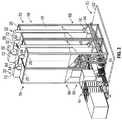
- FIG. 7is a partial bottom perspective view of four modular silos arranged in a group and connected together, according to an embodiment of the disclosure.
- FIG. 8is a bottom plan view of the four modular silos depicted in FIG. 7 , according to an embodiment of the disclosure.
- any references to “one embodiment” or “an embodiment”means that a particular element, feature, structure, or characteristic described in connection with the embodiment is included in at least one embodiment.
- the appearances of the phrase “in one embodiment” in various places in the specificationare not necessarily referring to the same embodiment.
- the present disclosuregenerally involves a system and methodology to facilitate handling of oilfield materials in a space efficient manner.
- the oilfield materialsmay be carried to a wellsite by suitable trucks and loaded into at least one modular silo without using air to carry the oilfield material.
- the oilfield materialsmay be moved into a plurality of modular silos by using vertical conveyors to move the oilfield material without blowers.
- each modular silocomprises an outer housing defining an enclosed interior for receiving the oilfield material.
- a corresponding vertical conveyoris positioned within the enclosed interior and is used to lift the oilfield material from a silo inlet, e.g. a hopper, to an upper portion of the modular silo without utilizing airflow to carry the oilfield materials.
- the outflow of oilfield material through a silo outletmay be gravity controlled so as to selectively release the desired amount of material into a blending system or other suitable equipment positioned underneath the modular silo.
- a vertical silois designed as a modular silo which may be carried by an over-the-road truck.
- Truckrefers to a transport vehicle, such as an articulated truck having a trailer pulled by a tractor.
- the modular silois carried by the trailer of the truck.
- the truckalso may comprise a straight truck or other suitable truck designed to carry the modular silo and to transport the modular silo over public roadways.
- the modular silois erected from the truck to a vertical position at a wellsite to provide an efficient solution for proppant delivery that avoids bottlenecks associated with existing systems.
- a cranemay be used to lift the modular silo and place the modular silo onto a support structure.
- a conveyorsuch as a mechanical belt conveyor
- the mechanical belt conveyorcan be backed-over by a trailer hauling the oilfield material with multiple nozzles overlapping the mechanical belt conveyor, or other types of haulers may also be used, such as tail dumps and live bottom trailers.
- the vertical conveyormay comprise a bucket elevator or other type of vertical conveyor capable of conveying the oilfield material to an upper end of the modular silo a substantial distance, e.g. 30 (9.144 meters) to 70 (21.336 meters) feet, above the wellsite surface.
- the conveyor moving the oilfield material to the modular silo and the vertical conveyormay be enclosed to provide a dust free solution for handling oilfield material at much higher rates with greater energy efficiency and lower attrition than that achieved with existing pneumatic, e.g. blower, type conveyance systems.
- the outer housingmay have a substantially rectangular shape defining four corners (which may form pointed vertices or be rounded.
- the modular silomay be transported on a trailer having a gooseneck.
- the vertical conveyormay extend beyond a top of the outer housing and be offset towards one of the corners so as to avoid the gooseneck of the trailer.
- a plurality of the modular silosmay be grouped together so that feeders of the plurality of modular silos provide oilfield material to a common area, e.g. to a truck mounted blending system having a proppant metering/rate control system, or other portable blender or blending system positioned beneath the modular silos.
- a common areae.g. to a truck mounted blending system having a proppant metering/rate control system, or other portable blender or blending system positioned beneath the modular silos.
- the common areamay be located below and overlaps the outer housings of the modular silos.
- some or all of the modular silosmay be divided into compartments.
- individual modular silosmay have a plurality of internal compartments for holding different types of oilfield materials.
- Individual silosalso may be divided into main storage compartments and secondary storage compartments located below the main storage compartments.
- the main storage compartmentmay be used to gravity feed oilfield material to an outlet feeder for distribution into the blender.
- Some systemsmay utilize a belt feeder or other type of feeder system instead of gravity feed.
- the secondary storage compartmentmay be exposed to the internal vertical conveyor and proppant from the secondary storage compartment may continually be lifted and discharged into the main storage compartment.
- the secondary compartments or other compartments of the modular silomay have separate features which enable independent filling of those particular compartments.
- outlet feedersmay be designed with controllable mechanisms, e.g. gates, which are adjustable to control the outflow of oilfield material.
- the modular silosmay be designed in a variety of sizes and shapes, including cylindrical shapes or rectangular shapes, selected to enable transport via a suitable over-the-road truck.
- the modular silosmay vary in size according to the proppant delivery plan for a given fracturing operation, but an example of a suitable modular silo may hold 2000-4000 (609.6-1219.2 meters) cubic feet of oilfield material.
- the modular silosare provided with sufficient clearance on the bottom side to form an unobstructed passage to enable a portable blender, such as a truck mounted blender, to be driven under a system of combined modular silos to receive oilfield material via gravity feed.
- the portable blendermay be mounted on a truck trailer which is backed into position under the outlet feeders of a plurality of modular silos.
- the modular silosmay be designed as standalone silos and in other embodiments, the modular silos may be designed for placement on a framework/support structure which supports the modular silos at a desired height.
- the blending systemmay be skid mounted in order to be transported on a trailer to the wellsite and then placed under the silo system by a suitable mechanical device, such as a winch.
- a systeme.g. a system for fracturing formations
- the fracturing systemmay comprise many types of equipment, including vehicles, storage containers, material handling equipment, pumps, control systems, and other equipment designed to facilitate the fracturing process.
- a formation fracturing system 20is illustrated in position at a wellsite 22 having a well 24 with at least one wellbore 26 extending down into a reservoir/formation.
- the formation fracturing system 20may comprise many types and arrangements of equipment, and the types or arrangements may vary from one fracturing operation to another.
- the formation fracturing system 20may comprise at least one modular silo 28 , e.g. a plurality of modular silos that may be transported over-the-road by trucks able to operate on public roadways.
- the modular silos 28are designed to store oilfield material such as a proppant used to prop open fractures upon fracturing of the subterranean formation, or guar used to increase the viscosity of a hydraulic fracturing fluid.
- oilfield materialsuch as a proppant used to prop open fractures upon fracturing of the subterranean formation, or guar used to increase the viscosity of a hydraulic fracturing fluid.
- several modular silos 28receive oilfield material via conveyors 30 , e.g. belt conveyors, and the oilfield material is lifted to an upper portion 31 of each modular silo by corresponding vertical conveyors 32 .
- the conveyors 30 and the vertical conveyors 32may operate by carrying the oilfield material instead of blowing the oilfield material to avoid erosion of components and dusting of the area. Additionally, the conveyors 30 and vertical conveyors 32 may be enclosed to further reduce dust as the oilfield material is delivered from an unload area 34 and into the modular silos 28 .
- oilfield material transport trucks 36may be used to deliver oilfield material to the unload area 34 .
- the trucks 36are tractor-trailer trucks having trailers 37 which may be backed over a portion of a selected conveyor 30 .
- the trailers 37can be gravity feed trailers or other types trailers capable of moving the oilfield material to the wellsite 22 .
- the trailersmay be operated to release the oilfield material onto a belt or other suitable carrier of the selected conveyor 30 for transfer to the associated modular silo or silos 28 along an enclosed pathway within the conveyor 30 .
- the formation fracturing system 20may comprise a variety of other components including water tanks (not shown) for supplying water that is mixed with the oilfield material to form the hydraulic fracturing fluid, e.g. proppant slurry, that may be pumped downhole into wellbore 26 via a plurality of pumps (not shown).
- pumpsmay be truck mounted pumps, e.g. pumping systems mounted on truck trailers designed for over-the-road transport.
- the multiple pumpsmay be coupled to a common manifold (not shown) designed to deliver the hydraulic fracturing fluid to the wellbore 26 .
- the formation fracturing system 20also may comprise a blending system 44 designed to blend oilfield material delivered from modular silos 28 .
- FIG. 2an embodiment of modular silos 28 coupled together into a cooperating unit is illustrated.
- a plurality of the modular silos 28e.g. four modular silos 28
- the modular silos 28is coupled together on a modular support structure, or framework, 50 which may be mounted on a pad 52 .
- the modular silos 28may be releasably mounted in a generally upright or vertical orientation on support structure 50 .
- Support structure 50is constructed with a plurality of silo receiving regions 54 on which the individual modular silos 28 may be mounted in a generally upright or vertical orientation.
- the support structure 50 and the silo receiving regions 54may be designed to elevate the modular silos 28 to a sufficient height so as to allow movement of portable blending system 44 to a position sufficiently beneath the modular silos 28 within the common area 47 in order to receive a controlled outflow of oilfield material.
- the support structure 50may be designed to allow a truck mounted blending system 44 to be driven, e.g. backed up, into position beneath the modular silos 28 , as illustrated.
- pad 52may be constructed in a variety of sizes and forms, including cement pads, compacted aggregate pads, pads constructed as portable structures, mixtures of these various structural elements, and/or other suitable pad types for supporting the plurality of modular silos 28 .
- modular silos 28each may be constructed with a silo frame 56 supporting the outer housing 49 which defines an enclosed interior 60 for holding oilfield material 62 (see also FIG. 3 ).
- oilfield material 62may comprise naturally occurring sand grains or gravel, man-made proppants, resin coated sand, high-strength ceramic materials, e.g. sintered bauxite, other solids such as fibers, mica, mixtures of different sized oilfield materials, mixtures of different types of oilfield materials, and/or other suitable oilfield materials.
- selected modular silos 28 or each of the modular silos 28may be divided into the compartments 64 designed to hold different types of oilfield materials 62 that may be selectively released from the modular silo 28 and blended via the blending system 44 .
- Each enclosed vertical conveyor 32is designed to lift oilfield material (e.g., with or without blowing) from an inlet 66 , e.g. an inlet hopper, disposed at a lower portion 68 to an upper discharge portion 70 for release into enclosed interior 60 through a vertical conveyor head 72 .
- the conveyor head 72may have a pivotable or otherwise movable discharge which is selectively controllable to deliver the desired oilfield material to a corresponding desired compartment 64 within a given modular silo 28 .
- the vertical conveyor 32may be positioned within enclosed interior 60 in a manner which limits escape of dust while providing a uniform modular unit that may be readily transported via an over-the-road truck, such as truck 36 with a suitably designed trailer.
- Vertical conveyor 32also may be constructed in a variety of forms.
- the vertical conveyor 32may be constructed as a bucket elevator 74 having a plurality of buckets 75 conveyed in a continuous loop lifting oilfield material 62 from inlet 66 to upper discharge portion 70 for discharge into enclosed interior 60 via vertical conveyor head 72 .
- the outflow of oilfield material 62 to the blending system 44may be through an outlet, e.g.
- the blending system 44may include a hopper 79 - 1 having an inlet 79 - 2 positioned below the feeder 76 .
- the outer housing 58overlaps the inlet 79 - 2 of the hopper 79 - 1 .
- the inlet 79 - 2 of the hopper 79 - 1may have a width 79 - 3 up to 12 (3.6576 meters) feet, and desirably between 8 (2.4384 meters) feet to 8.5 (2.5908 meters) feet.
- the hopper 79 - 1may also have an outflow control mechanism 79 - 4 which is similar to the outflow control mechanism 78 .
- outflow control mechanisms 78 and 79 - 4may comprise a controllable gate, e.g. hydraulic gate, control valve, or other flow control mechanism which is operated via control facility 48 or via another suitable control system.
- oilfield material 62is gravity fed through feeder 76 and the amount of outflow is governed by the outflow control mechanism 78 .
- the oilfield material 62 into a blender 79 - 5 of the blending system 44may be regulated by both of the outflow control mechanisms 78 and 79 - 4 .
- the outflow control mechanism 79 - 4may be maintained in a fixed open position while the outflow control mechanism 78 is regulated in real-time by the control facility 48 to control an amount of oilfield material 62 discharged into the blender 79 - 5 . Because the feeder 76 is within the confines of the hopper 79 - 1 , as the hopper 79 - 1 fills with oilfield material 62 , the oilfield material 62 will bear against the feeder 76 and form a plug. In this manner, the outflow control mechanism 79 - 4 is self-regulating and the outflow control mechanism 78 and the control facility 48 may solely control the amount of oilfield material 62 discharged into the blender 79 .
- the external conveyor or conveyors 30have a horizontal portion 80 with an exposed belt 82 , as illustrated in FIG. 4 that the trailers 37 of the trucks 36 can be backed over.
- the oilfield materialmay be unloaded via gravity from one of the trailers 37 which is backed over the horizontal portion 80 .
- the oilfield material dropped onto belt 82is conveyed onto an inclined portion 84 of conveyor 30 which may be enclosed and transports the oilfield material along an incline for release into at least one inlet 66 of a corresponding modular silo 28 .
- the inclined portion 84delivers the oilfield material into a hopper 86 of a diverter 87 .
- Diverter 87splits and diverts the oilfield material into downward flows which enter a plurality of inlets 66 of a plurality of modular silos 28 .
- the diverter 87may be designed to deliver proppant from conveyor 30 into a pair of inlets 66 associated with adjacent modular silos 28 .
- the oilfield materialis then lifted by the vertical conveyor 32 of each modular silo 28 .
- the oilfield material unloaded from truck 36is immediately moved into an enclosed system and is automatically conveyed into the enclosed interiors 60 of adjacent modular silos 28 without releasing dust into the surrounding environment.
- the horizontal portion 80is designed to enhance the rate at which oilfield material can be transferred into the modular silos 28 from the trailer 37 .
- the trailer 37may be provided with multiple outlets 88 - 1 , 88 - 2 and 88 - 3 which are spaced apart on the underside of the trailer 37 .
- three outlets 88 - 1 , 88 - 2 , and 88 - 3are shown and described, more or less outlets can be provided on the underside of the trailer 37 .
- the horizontal portion 80is provided with a first end 89 - 1 , a second end 89 - 2 and a length 89 - 3 extending between the first end 89 - 1 and the second end 89 - 2 .
- the first end 89 - 1overlaps the inclined portion 84 so as to transfer the oilfield material onto the inclined portion 84 from the trailer 37 of the truck 36 .
- the horizontal portion 80may have a height above the ground sufficient to permit the trailer 37 to be backed over the horizontal portion 80 and positioned underneath the outlets 88 - 1 , 88 - 2 , and 88 - 3 and between the wheels of the trailer 37 .
- the horizontal portionmay have a height of less than 12 inches, and desirably between 6-8 inches.
- the length 89 - 3 of the horizontal portion 80may be sufficient to be positioned in the unload area and simultaneously under all of the multiple outlets 88 - 1 , 88 - 2 and 88 - 3 .
- the length 89 - 3may be in a range from 8 (2.4384 meters) feet to 51 (15.5448 meters) feet.
- the oilfield materialmay be simultaneously delivered through the outlets 88 - 1 , 88 - 2 and 88 - 3 of the trailer 37 and onto the exposed belt 82 of the horizontal portion 80 .
- the horizontal portion 80also has a first side 90 - 1 , a second side 90 - 2 extending substantially parallel to the first side 90 - 1 , and a width 91 extending between the first side 90 - 1 and the second side 90 - 2 .
- the width 91is designed to fit in a space between the wheels of the trailer 37 so that the trailer 37 can be backed over the horizontal portion 80 .
- the width 91can be approximately two (0.6096 meters) feet.
- each modular silo 28may be designed as a modular unit used alone or in cooperation with other silos 28 .
- the modularity along with the design and sizing of the modular silos 28enables transport of individual modular silos 28 over public highways via trucks 36 .
- a suitable truck 36may comprise a tractor 92 - 1 pulling a gooseneck trailer 92 - 2 appropriately sized to receive one of the modular silos 28 in a lateral, e.g. horizontal, orientation.
- the gooseneck trailer 92 - 2has a gooseneck 92 - 3 connecting the gooseneck trailer 92 - 2 to the tractor 92 - 1 .
- the modular silo 28is constructed such that the vertical conveyor head 72 of the vertical conveyor 32 is disposed along a side of the modular silo 28 and extends from a closed top 94 of the outer housing 58 of the modular silo 28 along a side 95 - 1 of the gooseneck 92 - 3 .
- the vertical conveyor head 72overlaps with the side 95 of the gooseneck 92 - 3 , and may avoid overlapping with a top 95 - 2 of the gooseneck 92 - 3 .
- the vertical conveyor 32may extend between one inch and ten (3.048 meters) feet beyond the closed top 94 of the outer housing 58 in order to enable transport of the modular silo 28 on the gooseneck trailer 92 - 2 , as illustrated.
- the gooseneck trailer 92 - 2can be a conventionally styled gooseneck trailer, for example.
- the modular silo 28includes silo frame 56 which is designed for engagement with support structure 50 at one of the silo receiving regions 54 .
- silos 28may be constructed in other types of configurations.
- each modular silo 28may be constructed as a standalone silo.
- silo frame 56may be designed to engage a silo support pad located at the base of the modular silo 28 .
- a variety of outriggersmay be used in cooperation with silo support pad and/or silo frame 56 to stabilize the modular silo 28 when pivoted into its upright position.
- outriggersmay be hydraulically, electrically, pneumatically, manually, or otherwise actuatable between a retracted position and an extended position to support the modular silo 28 in the vertical position.
- outriggers 98may be mounted to the support structure 50 to stabilize the support structure 50 when the modular silos 28 are mounted in an upright position on the support structure 50 , as shown in FIG. 1 .
- the modular silos 28have been constructed in a manner which goes against conventional wisdom.
- conventional wisdomwould center the vertical conveyor 32 on a centerline of the modular silo in order to balance the modular silos 28 on the trailers 37 .
- the vertical conveyor 32 and the feeder 76 of the modular silos 28may be arranged on a same side of the outer housing 58 so as to facilitate the formation of the modular silos 28 into the cooperating unit shown and described above with respect to FIGS. 1 and 2 , although the modular silos 28 may not be balanced on the trailers 37 .
- FIG. 1the vertical conveyor 32 and the feeder 76 of the modular silos 28 may be arranged on a same side of the outer housing 58 so as to facilitate the formation of the modular silos 28 into the cooperating unit shown and described above with respect to FIGS. 1 and 2 , although the modular silos 28 may not be balanced on the trailers 37 .
- the outer housing 58has a substantially rectangular shape defining four corners 107 - 1 , 107 - 2 , 107 - 3 and 107 - 4 and each quadrant 106 - 1 , 106 - 2 , 106 - 3 and 106 - 4 encompasses one of the corners 107 - 1 , 107 - 2 , 107 - 3 and 107 - 4 .
- the first centerline 102also divides the outer housing 58 into a first half 108 and a second half 110 with the first quadrant 106 - 1 encompassed within the first half 108 .
- the vertical conveyor 32is mounted to the outer housing 58 and extends from the lower portion 68 to the upper portion 100 and may be within 5 degrees of parallel to the first centerline 102 .
- the vertical conveyor 32may be located within the second quadrant 106 - 2 of the quadrants 106 - 1 , 106 - 2 , 106 - 3 and 106 - 4 and positioned adjacent to the first quadrant 106 - 1 , the corner 107 - 4 and within the first half 108 .
- the vertical conveyor 32has third centerline 111 which is offset from the first centerline 102 such that the third centerline 111 is horizontally offset from and clears the side 95 - 1 of the gooseneck trailer 92 - 3 .
- the third centerline 111can be offset between two (0.6096 meters) feet and seven (2.1336 meters) feet from the first centerline 102 .
- the corners 107 - 1 , 107 - 2 , 107 - 3 and 107 - 4can either be shaped as a vertex, or rounded in order to provide a stronger outer housing 58 .
- the sides of the outer housing 58may be planar or concavely shaped in order to bulge outwardly in a predetermined manner when the oilfield material 62 is loaded into the enclosed interior 60 of the modular silo 28 .
- FIG. 7is a partial bottom perspective view of a cooperating unit 120 formed of four modular silos 28 arranged in a group and connected together, according to an embodiment of the disclosure.
- FIG. 8is a bottom plan view of the cooperating unit 120 having the four modular silos 28 depicted in FIG. 7 .
- the cooperating unit 120is provided with a first group 124 of modular silos 28 , and a second group 126 of modular silos 28 .
- the first group 124 and the second group 126are substantially identical and may be constructed to form mirror images of one another.
- the first group 124is provided with a first modular silo 28 a and a second modular silo 28 b .
- the second group 126is provided with a third modular silo 28 c and a fourth modular silo 28 d .
- the first modular silo 28 a and the second modular silo 28 bare similar in construction with the exception that the second modular silo 28 b is a mirror image of the first modular silo 28 a to permit feeders 76 a and 76 b to be positioned adjacent to each other and within the common area 47 .
- the first and fourth modular silos 28 a and 28 dare similar to one another, and the second and third modular silos 28 b and 28 c are also similar to one another.
- the third and fourth modular silos 28 c and 28 dare similar in construction with the exception that the fourth modular silo 28 d is constructed to be a mirror image of the third modular silo 28 c.
- the first modular silo 28 ais provided with a first housing side 134 positioned adjacent to a vertical conveyor 32 a and the feeder 76 a .
- the second modular silo 28 bis provided with a first housing side 136 which is also positioned adjacent to a vertical conveyor 32 b and the feeder 76 b .
- the first housing sides 134 and 136contact each other or are positioned in close proximity to neighbor each other.
- the feeders 76 a and 76 bare desirably positioned within 12 (3.6576 meters) feet of each other, and more desirably positioned within eight (2.4384 meters) feet of each other.
- the feeders 76 a and 76 bare positioned adjacent to the first housing sides 134 and 136 , e.g., desirably within six (1.8288 meters) feet of the first housing sides 134 and 136 , and more desirably within four (1.2192 meters) feet of the first housing sides 134 and 136 such that the feeders 76 a and 76 b discharge the oilfield material into the hopper 79 - 1 .
- the first modular silo 28 ais also provided with a second housing side 140 positioned adjacent to the vertical conveyor 32 a and extending generally normal to the first housing side 134 .
- the second modular silo 28 bis also provided with a second housing side 142 which is also positioned adjacent to the vertical conveyor 32 b and extending generally normal to the first housing side 136 .
- the second housing sides 140 and 142are in a co-planar relationship.
- the feeders 76 a and 76 bmay be positioned adjacent to the second housing sides 140 and 142 , e.g., within twelve inches of the second housing sides 134 and 136 .
- the second housing sides 140 and 142extend parallel to the second housing sides 144 and 146 of the modular silos 28 c and 28 d.
- the arrangement and components of formation fracturing system 20may vary substantially depending on the parameters of a given fracturing operation.
- the modular silos 28may be used individually or in groups of standalone silos or silos securely mounted on a support structure.
- the modular silosmay be mounted at a sufficient height to direct outflowing oilfield material through an outflow feeder positioned at the bottom of the enclosed interior.
- the feedersmay be positioned to direct outflow of oilfield material from a higher compartment within the modular silo.
- the modular silosmay comprise an enclosed interior divided into a plurality of compartments for holding different types of oilfield material that may be selectively metered to a blender for blending into a desired mixture which is then pumped downhole into the wellbore.
- various belt conveyors or other types of conveyorsmay be enclosed to deliver oilfield material from the unload area to the upright, modular silos.
- the modular silosalso may incorporate a variety of vertical conveyors for lifting the oilfield material to an upper discharge region of the modular silos.
- Various arrangements of upright silosenable storage of a substantial quantity of oilfield materials that may be readily supplied for use in a fracturing operation.
- the upright arrangement of modular silosalso provides for an efficient use of wellsite space.
- the enclosed system for storing and delivering oilfield materialprovides a clean wellsite substantially free of dust production.
- various numbers and arrangements of modular silos, conveyors, blenders, and other wellsite equipmentmay be employed.
Landscapes
- Engineering & Computer Science (AREA)
- Architecture (AREA)
- Life Sciences & Earth Sciences (AREA)
- Geology (AREA)
- Mining & Mineral Resources (AREA)
- Mechanical Engineering (AREA)
- Structural Engineering (AREA)
- Civil Engineering (AREA)
- General Engineering & Computer Science (AREA)
- Fluid Mechanics (AREA)
- Geochemistry & Mineralogy (AREA)
- General Life Sciences & Earth Sciences (AREA)
- Physics & Mathematics (AREA)
- Environmental & Geological Engineering (AREA)
- Preparation Of Clay, And Manufacture Of Mixtures Containing Clay Or Cement (AREA)
- Filling Or Emptying Of Bunkers, Hoppers, And Tanks (AREA)
- Consolidation Of Soil By Introduction Of Solidifying Substances Into Soil (AREA)
- Weight Measurement For Supplying Or Discharging Of Specified Amounts Of Material (AREA)
Abstract
Description
Claims (23)
Priority Applications (3)
| Application Number | Priority Date | Filing Date | Title |
|---|---|---|---|
| US13/836,405US10895114B2 (en) | 2012-08-13 | 2013-03-15 | System and method for delivery of oilfield materials |
| PCT/US2013/054283WO2014028316A1 (en) | 2012-08-13 | 2013-08-09 | System and method for delivery of oilfield materials |
| ARP130102871AAR092115A1 (en) | 2012-08-13 | 2013-08-13 | SYSTEM AND METHOD FOR THE ADMINISTRATION OF OIL FIELD MATERIALS |
Applications Claiming Priority (4)
| Application Number | Priority Date | Filing Date | Title |
|---|---|---|---|
| US201261682734P | 2012-08-13 | 2012-08-13 | |
| US201261746154P | 2012-12-27 | 2012-12-27 | |
| US201261746158P | 2012-12-27 | 2012-12-27 | |
| US13/836,405US10895114B2 (en) | 2012-08-13 | 2013-03-15 | System and method for delivery of oilfield materials |
Publications (2)
| Publication Number | Publication Date |
|---|---|
| US20140044508A1 US20140044508A1 (en) | 2014-02-13 |
| US10895114B2true US10895114B2 (en) | 2021-01-19 |
Family
ID=50065115
Family Applications (4)
| Application Number | Title | Priority Date | Filing Date |
|---|---|---|---|
| US13/839,368AbandonedUS20140041322A1 (en) | 2012-08-13 | 2013-03-15 | System and method for delivery of oilfield materials |
| US13/836,405Expired - Fee RelatedUS10895114B2 (en) | 2012-08-13 | 2013-03-15 | System and method for delivery of oilfield materials |
| US13/838,872ActiveUS9752389B2 (en) | 2012-08-13 | 2013-03-15 | System and method for delivery of oilfield materials |
| US13/839,088Active2034-02-06US10077610B2 (en) | 2012-08-13 | 2013-03-15 | System and method for delivery of oilfield materials |
Family Applications Before (1)
| Application Number | Title | Priority Date | Filing Date |
|---|---|---|---|
| US13/839,368AbandonedUS20140041322A1 (en) | 2012-08-13 | 2013-03-15 | System and method for delivery of oilfield materials |
Family Applications After (2)
| Application Number | Title | Priority Date | Filing Date |
|---|---|---|---|
| US13/838,872ActiveUS9752389B2 (en) | 2012-08-13 | 2013-03-15 | System and method for delivery of oilfield materials |
| US13/839,088Active2034-02-06US10077610B2 (en) | 2012-08-13 | 2013-03-15 | System and method for delivery of oilfield materials |
Country Status (7)
| Country | Link |
|---|---|
| US (4) | US20140041322A1 (en) |
| CN (1) | CN104640787B (en) |
| AU (2) | AU2013302971A1 (en) |
| CA (1) | CA2880909C (en) |
| RU (1) | RU2639079C2 (en) |
| SA (1) | SA515360032B1 (en) |
| WO (2) | WO2014028319A1 (en) |
Cited By (2)
| Publication number | Priority date | Publication date | Assignee | Title |
|---|---|---|---|---|
| US12221275B2 (en) | 2021-10-29 | 2025-02-11 | DynaEnergetics Europe GmbH | Mobile perforating bank unit and modular storage container |
| US12221299B1 (en) | 2024-02-22 | 2025-02-11 | Solaris Oilfield Site Services Operating Llc | Systems and methods for filling a proppant silo |
Families Citing this family (72)
| Publication number | Priority date | Publication date | Assignee | Title |
|---|---|---|---|---|
| US10300830B2 (en) | 2011-10-24 | 2019-05-28 | Solaris Oilfield Site Services Operating Llc | Storage and blending system for multi-component granular compositions |
| MX348588B (en)* | 2011-10-24 | 2017-06-20 | Solaris Oilfield Site Services Operating Llc | Fracture sand silo system and methods of deployment and retraction of same. |
| US10836568B2 (en) | 2011-10-24 | 2020-11-17 | Solaris Oilfield Site Services Operating Llc | Blender hopper control system for multi-component granular compositions |
| US9421899B2 (en) | 2014-02-07 | 2016-08-23 | Oren Technologies, Llc | Trailer-mounted proppant delivery system |
| US20140041322A1 (en) | 2012-08-13 | 2014-02-13 | Schlumberger Technology Corporation | System and method for delivery of oilfield materials |
| US10533406B2 (en) | 2013-03-14 | 2020-01-14 | Schlumberger Technology Corporation | Systems and methods for pairing system pumps with fluid flow in a fracturing structure |
| US9534604B2 (en)* | 2013-03-14 | 2017-01-03 | Schlumberger Technology Corporation | System and method of controlling manifold fluid flow |
| US9452394B2 (en)* | 2013-06-06 | 2016-09-27 | Baker Hughes Incorporated | Viscous fluid dilution system and method thereof |
| US10633174B2 (en) | 2013-08-08 | 2020-04-28 | Schlumberger Technology Corporation | Mobile oilfield materialtransfer unit |
| US10150612B2 (en) | 2013-08-09 | 2018-12-11 | Schlumberger Technology Corporation | System and method for delivery of oilfield materials |
| US10464071B2 (en) | 2013-09-18 | 2019-11-05 | Schlumberger Technology Corporation | System and method for preparing a treatment fluid |
| US9593565B2 (en) | 2013-09-18 | 2017-03-14 | Schlumberger Technology Corporation | Wellsite handling system for packaged wellsite materials and method of using same |
| US9322246B2 (en)* | 2013-09-20 | 2016-04-26 | Schlumberger Technology Corporation | Solids delivery apparatus and method for a well |
| CA2830145C (en)* | 2013-10-17 | 2018-03-20 | Quickthree Solutions Inc. | Granular material storage with input and output |
| US9925904B2 (en) | 2013-12-12 | 2018-03-27 | Schlumberger Technology Corporation | Adjustment apparatus for container installation |
| US9862538B2 (en) | 2013-12-12 | 2018-01-09 | Schlumberger Technology Corporation | Mobile erector system |
| US12102970B2 (en) | 2014-02-27 | 2024-10-01 | Schlumberger Technology Corporation | Integrated process delivery at wellsite |
| US11819810B2 (en) | 2014-02-27 | 2023-11-21 | Schlumberger Technology Corporation | Mixing apparatus with flush line and method |
| US11453146B2 (en) | 2014-02-27 | 2022-09-27 | Schlumberger Technology Corporation | Hydration systems and methods |
| US10449503B2 (en) | 2014-03-04 | 2019-10-22 | Basf Corporation | Temporary addition or injection system |
| GB2524809A (en)* | 2014-04-03 | 2015-10-07 | Nectar Group Ltd | Bulk hopper |
| CA3188903A1 (en)* | 2014-06-30 | 2016-01-07 | Liberty Oilfield Services Llc | Compact articulation mechanism |
| US10213755B2 (en) | 2014-08-15 | 2019-02-26 | Schlumberger Technology Corporation | Wellsite mixer sensing assembly and method of using same |
| US20160152421A1 (en)* | 2014-11-28 | 2016-06-02 | Binod Kumar Bawri | System and method for loading and unloading material in bulk form |
| US10551819B2 (en)* | 2014-12-11 | 2020-02-04 | Schlumberger Technology Corporation | Automated multi-silo aggregate management |
| CA2885668C (en)* | 2015-03-24 | 2022-05-03 | Quickthree Solutions Inc. | Transportable receiving and storage system with redundancy |
| US11192731B2 (en) | 2015-05-07 | 2021-12-07 | Halliburton Energy Services, Inc. | Container bulk material delivery system |
| WO2016178692A1 (en)* | 2015-05-07 | 2016-11-10 | Halliburton Energy Services, Inc. | On-location sand delivery system & conveyor and process |
| CN105019878B (en)* | 2015-07-21 | 2019-08-16 | 三一石油智能装备有限公司 | A kind of fracturing unit truck |
| WO2017014771A1 (en) | 2015-07-22 | 2017-01-26 | Halliburton Energy Services, Inc. | Blender unit with integrated container support frame |
| AU2015402766A1 (en)* | 2015-07-22 | 2017-05-18 | Halliburton Energy Services, Inc. | Mobile support structure for bulk material containers |
| CN111880372B (en)* | 2015-08-27 | 2023-10-10 | 富士胶片株式会社 | Photosensitive composition, image forming method, film forming method, resin, image, and film |
| US11203495B2 (en) | 2015-11-25 | 2021-12-21 | Halliburton Energy Services, Inc. | Sequencing bulk material containers for continuous material usage |
| US11047717B2 (en) | 2015-12-22 | 2021-06-29 | Halliburton Energy Services, Inc. | System and method for determining slurry sand concentration and continuous calibration of metering mechanisms for transferring same |
| US11320079B2 (en) | 2016-01-27 | 2022-05-03 | Liberty Oilfield Services Llc | Modular configurable wellsite surface equipment |
| US11773315B2 (en) | 2016-03-01 | 2023-10-03 | Schlumberger Technology Corporation | Well treatment methods |
| US11192074B2 (en) | 2016-03-15 | 2021-12-07 | Halliburton Energy Services, Inc. | Mulling device and method for treating bulk material released from portable containers |
| WO2017164880A1 (en) | 2016-03-24 | 2017-09-28 | Halliburton Energy Services, Inc. | Fluid management system for producing treatment fluid using containerized fluid additives |
| WO2017171797A1 (en) | 2016-03-31 | 2017-10-05 | Halliburton Energy Services, Inc. | Loading and unloading of bulk material containers for on site blending |
| CA3014878C (en)* | 2016-05-24 | 2021-04-13 | Halliburton Energy Services, Inc. | Containerized system for mixing dry additives with bulk material |
| US10919693B2 (en) | 2016-07-21 | 2021-02-16 | Halliburton Energy Services, Inc. | Bulk material handling system for reduced dust, noise, and emissions |
| US11186431B2 (en) | 2016-07-28 | 2021-11-30 | Halliburton Energy Services, Inc. | Modular bulk material container |
| WO2018034641A1 (en) | 2016-08-15 | 2018-02-22 | Halliburton Energy Services, Inc. | Vacuum particulate recovery systems for bulk material containers |
| US11186454B2 (en) | 2016-08-24 | 2021-11-30 | Halliburton Energy Services, Inc. | Dust control systems for discharge of bulk material |
| US11066259B2 (en) | 2016-08-24 | 2021-07-20 | Halliburton Energy Services, Inc. | Dust control systems for bulk material containers |
| CA3040314A1 (en)* | 2016-11-03 | 2018-05-11 | Westcap Ag Corp. | Mobile collapsible storage silo |
| WO2018101959A1 (en) | 2016-12-02 | 2018-06-07 | Halliburton Energy Services, Inc. | Transportation trailer with space frame |
| US10315850B2 (en) | 2017-07-13 | 2019-06-11 | 1875452 Alberta Ltd. | Proppant conveyor systems and methods of use |
| WO2019140331A1 (en)* | 2018-01-12 | 2019-07-18 | Mgb Oilfield Solutions, Llc | Dry additive and fluid mixing system, assembly and method |
| CA3001219C (en)* | 2018-04-12 | 2020-04-28 | Quickthree Solutions Inc. | Silo transport safe retrieval system |
| CA3105632A1 (en) | 2018-07-23 | 2020-01-30 | Westcap Ag Corp. | Skid mounted storage system with collapsible silo for flowable material |
| US12077372B2 (en) | 2018-09-14 | 2024-09-03 | National Oilwell Varco, L.P. | Proppant supply system |
| US11506314B2 (en) | 2018-12-10 | 2022-11-22 | National Oilwell Varco Uk Limited | Articulating flow line connector |
| US11267663B2 (en) | 2019-01-15 | 2022-03-08 | Quickthree Technology, Llc | Bottom dump pneumatic material handling system |
| CA3125757A1 (en) | 2019-01-22 | 2020-07-30 | Westcap Ag Corp. | Portable conveyor system including pivotable and extendable feed conveyors for feeding particulate material into an elevating assembly |
| US11828150B2 (en) | 2019-07-01 | 2023-11-28 | National Oilwell Varco, L.P. | Smart manifold |
| CA3143799A1 (en) | 2019-07-01 | 2021-01-07 | National Oilwell Varco, L.P. | Close coupled fluid processing system |
| WO2021055885A1 (en)* | 2019-09-18 | 2021-03-25 | Bowlin Enterprises, Llc | Portable sand drying system and method |
| US11912608B2 (en) | 2019-10-01 | 2024-02-27 | Owens-Brockway Glass Container Inc. | Glass manufacturing |
| US11661291B2 (en) | 2019-10-31 | 2023-05-30 | Sandbox Enterprises, Llc | Support apparatus for proppant storage containers |
| US11885206B2 (en)* | 2019-12-30 | 2024-01-30 | U.S. Well Services, LLC | Electric motor driven transportation mechanisms for fracturing blenders |
| US11880804B1 (en) | 2020-04-29 | 2024-01-23 | Prop Sense Canada Ltd. | System and method for automated inventory, transport, management, and storage control in hydraulic fracturing operations |
| US11760584B2 (en) | 2020-07-14 | 2023-09-19 | Quickthree Technology, Llc | Flow control for bottom dump pneumatic material handling |
| US12291410B2 (en) | 2020-10-01 | 2025-05-06 | Owens-Brockway Glass Container Inc. | Bulk material handling methods, systems, subsystems, and apparatuses |
| US12404091B2 (en) | 2020-10-01 | 2025-09-02 | Owens-Brockway Glass Container Inc. | Bulk material receiving, conveying, storing, and dispensing |
| US12304725B2 (en) | 2020-10-01 | 2025-05-20 | Owens-Brockway Glass Container Inc. | Bulk material receiving, conveying, storing, and dispensing |
| US11702916B2 (en) | 2020-12-22 | 2023-07-18 | National Oilwell Varco, L.P. | Controlling the flow of fluid to high pressure pumps |
| CA3155282A1 (en) | 2021-04-15 | 2022-10-15 | Rocky Mountain Investor Holdings, Inc. | Reloadable containerized system for wet and dry proppants and methods of making and using same |
| US11867044B2 (en)* | 2021-04-19 | 2024-01-09 | Proppant Express Solutions, Llc | Proppant dispensing system |
| US11465155B1 (en) | 2021-06-16 | 2022-10-11 | Propflow, Llc | Wellsite wet screening systems for proppants and methods of using same |
| US12157646B2 (en)* | 2021-07-14 | 2024-12-03 | Jdl Canada Inc. | Storage silo apparatus with an integrated vertical conveyor |
| WO2024186307A1 (en)* | 2023-03-03 | 2024-09-12 | Aquasmart Enterprises, Llc | Mobile coating unit to produce various, changeable coated proppants with artificial intelligence option, configuration and method of use |
Citations (244)
| Publication number | Priority date | Publication date | Assignee | Title |
|---|---|---|---|---|
| US559965A (en) | 1896-05-12 | bierstadt | ||
| US896233A (en) | 1907-06-20 | 1908-08-18 | Finlay R Mcqueen | Storage-bin. |
| US1526527A (en) | 1924-02-01 | 1925-02-17 | Morgan R Butler | Material-handling equipment |
| US1560826A (en) | 1924-04-24 | 1925-11-10 | Kirschbraun Lester | Apparatus for making bituminous emulsion |
| US1576940A (en) | 1923-03-02 | 1926-03-16 | Specialty Engineering Company | Pocket or storage bin |
| US2073652A (en) | 1936-03-12 | 1937-03-16 | John F Robb | Central mixing plant |
| US2099898A (en) | 1935-09-16 | 1937-11-23 | Charles A Criqui | Portable foundation for machinery |
| US2357583A (en) | 1942-07-29 | 1944-09-05 | John S Franco | System and apparatus for handling concrete |
| US2735839A (en) | 1950-12-27 | 1956-02-21 | schrenk | |
| US2774497A (en) | 1953-04-16 | 1956-12-18 | William E Martin | Notched gooseneck trailer construction |
| US2792262A (en) | 1955-04-08 | 1957-05-14 | Halliburton Oil Well Cementing | Pneumatically discharged vessel for pulverulent materials |
| US2858950A (en) | 1956-05-18 | 1958-11-04 | Hyster Co | Heavy duty bed ramp trailer |
| US3155248A (en) | 1962-12-31 | 1964-11-03 | Seatrain Lines Inc | Vehicle-container |
| US3170560A (en) | 1963-07-22 | 1965-02-23 | Robert W Obmascher | Portable unloaders |
| US3208616A (en) | 1963-07-19 | 1965-09-28 | Haskins Roy | Portable storage bin |
| US3263436A (en)* | 1965-02-05 | 1966-08-02 | Koehring Co | Method of and apparatus for precooling concrete mix ingredients |
| US3314557A (en) | 1965-04-16 | 1967-04-18 | Sr Walter J Sackett | Tank type bulk blending plant |
| US3394961A (en) | 1966-06-07 | 1968-07-30 | Matte Gedeon | Collapsible camper |
| US3451986A (en) | 1964-06-04 | 1969-06-24 | Aquitaine Petrole | Process and apparatus for the mass polymerisation of aryl vinyl compounds |
| US3490632A (en) | 1967-11-08 | 1970-01-20 | Hoover Ball & Bearing Co | Portable bin assembly |
| US3497327A (en) | 1966-02-01 | 1970-02-24 | Wolfgang Kehse | Apparatus for reacting flowable and gaseous materials with each other |
| US3560053A (en) | 1968-11-19 | 1971-02-02 | Exxon Production Research Co | High pressure pumping system |
| US3618801A (en) | 1970-05-08 | 1971-11-09 | Dow Chemical Co | Combination tank-trailer assembly |
| US3666129A (en) | 1970-02-16 | 1972-05-30 | Roy Haskins | Detachable storage bin and trailer |
| US3687319A (en) | 1971-01-14 | 1972-08-29 | Vernon F Adam | Trailer for erecting and transporting storage tanks |
| US3743108A (en) | 1972-01-31 | 1973-07-03 | Clark Equipment Co | Outrigger |
| US3756443A (en) | 1972-06-02 | 1973-09-04 | Hyster Co | Folding gooseneck trailer |
| US3787479A (en) | 1970-03-05 | 1974-01-22 | Inventa Ag | Process for the continuous transesterification of dicarboxylic acid alkyl esters with diols |
| US3842910A (en) | 1973-10-04 | 1974-10-22 | Dow Chemical Co | Well fracturing method using liquefied gas as fracturing fluid |
| US3883019A (en) | 1973-09-04 | 1975-05-13 | Jr O Duane Hansen | Power actuated folding goose neck trailer |
| US3883148A (en) | 1974-02-11 | 1975-05-13 | Certified Stainless Services | Trailer tank |
| US3894645A (en) | 1974-07-26 | 1975-07-15 | Transport Trailers Inc | Folding gooseneck trailer |
| US3938673A (en)* | 1974-10-07 | 1976-02-17 | Perry Jr L F | Portable concrete batch plant |
| US3974602A (en) | 1975-02-10 | 1976-08-17 | Robert Pohl | Mono-coque building structure and methods |
| US3985254A (en) | 1973-07-25 | 1976-10-12 | Societe Mobiliere Industrielle | System and method for loading and unloading a storage apparatus from a vehicle |
| US3998433A (en) | 1974-05-10 | 1976-12-21 | Funken Co., Ltd. | Continuous mixing machine for moistening powdered material |
| US4026441A (en) | 1976-04-05 | 1977-05-31 | Jones Richard C | Roof-gravel removal apparatus |
| US4077612A (en) | 1973-12-04 | 1978-03-07 | Ricciardi Ronald J | Metering and wetting system |
| US4079150A (en)* | 1976-01-24 | 1978-03-14 | Plate Kofasil Gesellschaft Mit Beschrankter Haftung | Ensiling agent for fodder plants and a method of fermentating fodder plants |
| US4090623A (en) | 1977-02-22 | 1978-05-23 | Societe Internationale d'Investissements et de Participations par abreviation Interpar | System for handling a container |
| US4103793A (en) | 1977-05-06 | 1978-08-01 | Talbert Manufacturing, Inc. | Folding gooseneck trailer with positioning system |
| US4111314A (en) | 1977-05-18 | 1978-09-05 | Walnut Sand & Gravel Co. | Transportable silo |
| US4187047A (en) | 1978-03-09 | 1980-02-05 | Boeing Construction Equipment Company | System and apparatus for erecting a portable silo and elevator structure |
| US4209278A (en) | 1978-02-21 | 1980-06-24 | Halliburton Company | Chassis having articulated frame |
| US4222498A (en) | 1979-01-17 | 1980-09-16 | Astec Industries, Inc. | Control system for aggregate delivery system |
| US4248359A (en) | 1978-06-05 | 1981-02-03 | Astec Industries, Inc. | Weigh-out system for collapsible surge bin |
| US4249848A (en) | 1979-10-05 | 1981-02-10 | Griffin Cecil A | Transportable, collapsible vehicle loading hopper |
| US4268208A (en) | 1979-12-13 | 1981-05-19 | Cmi Corporation | Portable self-erecting silo apparatus |
| JPS5715828A (en) | 1980-07-03 | 1982-01-27 | Yamato Boring Kk | Continuous type mixer for powder and liquid |
| EP0048312A1 (en) | 1980-09-19 | 1982-03-31 | Nemo Ivarson | Method and apparatus for continuously mixing a liquid and powder |
| US4337014A (en) | 1980-11-28 | 1982-06-29 | Barber-Greene Company | Method and apparatus for erecting a portable silo and elevator |
| US4348146A (en) | 1978-06-05 | 1982-09-07 | Astec Industries, Inc. | Self-erecting surge bin |
| US4373857A (en) | 1980-07-14 | 1983-02-15 | Ruan, Incorporated | Method for transporting bulk fluid or particulate material |
| US4375343A (en) | 1980-08-25 | 1983-03-01 | Halliburton Company | Railcar transporting trailer |
| US4400126A (en) | 1981-08-13 | 1983-08-23 | Bernard Desourdy | Roadable storage container for bituminous mix |
| US4427133A (en) | 1980-01-23 | 1984-01-24 | Halliburton Company | Additive material metering system with weighing means |
| US4453829A (en) | 1982-09-29 | 1984-06-12 | The Dow Chemical Company | Apparatus for mixing solids and fluids |
| US4465420A (en) | 1982-03-03 | 1984-08-14 | Bituma-Stor, Inc. | Self-erecting portable paving mix silo |
| WO1985000046A1 (en) | 1983-06-14 | 1985-01-03 | Weyerhaeuser Company | Low consistency ozone bleaching reactor |
| US4561821A (en) | 1984-12-20 | 1985-12-31 | Bituma-Stor, Inc. | Portable self-erecting surge storage silo |
| US4579496A (en)* | 1984-12-18 | 1986-04-01 | Gerlach Stanley C | Mobile concrete batch plant |
| US4601628A (en) | 1983-01-17 | 1986-07-22 | Lowing Michael M | Storage structures |
| US4621972A (en) | 1985-02-19 | 1986-11-11 | Grotte Walter D | Silo mover |
| US4626166A (en) | 1985-11-06 | 1986-12-02 | Jolly Arthur E | Method for the placement of a trailer-mounted sand hopper |
| US4671665A (en) | 1985-03-21 | 1987-06-09 | Dowell Schlumberger Incorporated | Machine for mixing particles with a fluid composition |
| SU1341161A1 (en) | 1986-01-06 | 1987-09-30 | Предприятие П/Я А-3732 | Method of automatic control for process of producing calcium hydroxide |
| EP0241056A1 (en) | 1986-03-27 | 1987-10-14 | Compagnie Des Services Dowell Schlumberger | Mixer for pulverous and liquid materials, or liquid-liquid materials |
| US4701095A (en) | 1984-12-28 | 1987-10-20 | Halliburton Company | Transportable material conveying apparatus |
| US4775275A (en) | 1987-04-13 | 1988-10-04 | Perry L F | Mobile batch plants |
| US4808004A (en) | 1988-05-05 | 1989-02-28 | Dowell Schlumberger Incorporated | Mixing apparatus |
| US4832561A (en) | 1986-04-25 | 1989-05-23 | Hydro Mecanique Research S.A. | Loading system with trash silos |
| US4850750A (en) | 1985-07-19 | 1989-07-25 | Halliburton Company | Integrated blending control system |
| US4855960A (en) | 1982-04-30 | 1989-08-08 | Janssen Wilhelmus G E | Process and apparatus for the preparation of mortars |
| US4883363A (en) | 1987-09-08 | 1989-11-28 | Pillon Francis D | Device inter alia for uniformly distributing solid and/or liquid particles, and an assembly comprising such a device |
| US4899832A (en) | 1985-08-19 | 1990-02-13 | Bierscheid Jr Robert C | Modular well drilling apparatus and methods |
| US4907712A (en) | 1988-09-19 | 1990-03-13 | Stempin David R | Tank stabilizer |
| US4917560A (en) | 1989-01-19 | 1990-04-17 | Cmi Corporation | Twin bin self erect silo |
| US4925358A (en) | 1986-11-14 | 1990-05-15 | Spancrete Machinery Corporation | Trailerable earth digging apparatus |
| US4944646A (en) | 1989-01-12 | 1990-07-31 | Astec Industries, Inc. | Highway transportable material storage apparatus and frame assembly therefor |
| US5006034A (en) | 1988-05-27 | 1991-04-09 | Halliburton Company | Lifting apparatus |
| US5018932A (en) | 1987-09-30 | 1991-05-28 | Interpatent Anstalt | Apparatus for handling a load by arm, notably for a truck or trailer |
| FR2655007A1 (en) | 1989-11-28 | 1991-05-31 | Leveques Somerel Sa Ste Montbr | Assembly for hitching a towing vehicle and a trailer |
| US5035269A (en) | 1986-11-21 | 1991-07-30 | Emergency Containment Systems | Safety gas cylinder containment system |
| US5046856A (en) | 1989-09-12 | 1991-09-10 | Dowell Schlumberger Incorporated | Apparatus and method for mixing fluids |
| US5052486A (en) | 1989-09-08 | 1991-10-01 | Smith Energy Services | Method and apparatus for rapid and continuous hydration of polymer-based fracturing fluids |
| US5121989A (en) | 1990-03-12 | 1992-06-16 | Mcneilus Truck And Manufacturing, Inc. | Transportable concrete batching apparatus |
| US5190374A (en) | 1991-04-29 | 1993-03-02 | Halliburton Company | Method and apparatus for continuously mixing well treatment fluids |
| US5195861A (en) | 1989-04-13 | 1993-03-23 | Halliburton Company | Automatic rate matching system |
| US5201498A (en) | 1992-01-21 | 1993-04-13 | Akins Edward A | Flexible fencing system |
| US5236261A (en) | 1992-01-24 | 1993-08-17 | Hagenbuch Roy George Le | Conditioned ash surge bin |
| US5339996A (en) | 1993-04-26 | 1994-08-23 | Midwest Pre-Mix, Inc. | Portable mini silo system |
| US5362193A (en) | 1993-02-25 | 1994-11-08 | Astec Industries, Inc. | Self erecting asphalt production plant |
| US5382411A (en) | 1993-01-05 | 1995-01-17 | Halliburton Company | Apparatus and method for continuously mixing fluids |
| US5387736A (en) | 1993-08-30 | 1995-02-07 | Salomone Bros., Inc. | Portable decontamination system and method for environmental well drilling rigs |
| US5413154A (en) | 1993-10-14 | 1995-05-09 | Bulk Tank, Inc. | Programmable modular system providing controlled flows of granular materials |
| US5426137A (en) | 1993-01-05 | 1995-06-20 | Halliburton Company | Method for continuously mixing fluids |
| US5427497A (en) | 1993-10-15 | 1995-06-27 | Dillman; Bruce A. | Horizontal surge/storage silo |
| US5571281A (en) | 1996-02-09 | 1996-11-05 | Allen; Thomas E. | Automatic cement mixing and density simulator and control system and equipment for oil well cementing |
| US5667298A (en) | 1996-01-16 | 1997-09-16 | Cedarapids, Inc. | Portable concrete mixer with weigh/surge systems |
| US5775713A (en) | 1995-10-26 | 1998-07-07 | Peterson; Thomas W. | Collapsible goose-neck van trailer |
| US5777234A (en) | 1996-08-01 | 1998-07-07 | Kistler-Morse Corporation | Pre-straining apparatus and method for strain sensors |
| US5785421A (en) | 1996-10-22 | 1998-07-28 | Milek; Robert C. | Mobile modular concrete batch plant |
| US5795062A (en) | 1996-10-03 | 1998-08-18 | Hamilton Beach/Proctor-Silex, Inc. | Milkshake machine |
| US5822930A (en) | 1996-01-24 | 1998-10-20 | Klein; Darrel J. | Collapsible transportable deck for a house trailer or mobile home |
| RU10418U1 (en) | 1998-10-13 | 1999-07-16 | Открытое акционерное общество "Татарский научно-исследовательский и проектно-конструкторский институт нефтяного машиностроения" | UNIT MIXING |
| US6000840A (en) | 1997-12-17 | 1999-12-14 | Charles Ross & Son Company | Rotors and stators for mixers and emulsifiers |
| US6050743A (en) | 1995-11-28 | 2000-04-18 | Medinger; Jean Claude | Spreader for treating soil |
| US6186195B1 (en) | 1998-07-15 | 2001-02-13 | Windmoller & Holscher | Silo system |
| US6186654B1 (en)* | 1999-02-23 | 2001-02-13 | Guntert & Zimmerman Construction Division, Inc. | Portable and modular batching and mixing plant for concrete and the like |
| US6193402B1 (en) | 1998-03-06 | 2001-02-27 | Kristian E. Grimland | Multiple tub mobile blender |
| US6293689B1 (en) | 2000-09-20 | 2001-09-25 | Guntert & Zimmerman Const. Div., Inc. | High volume portable concrete batching and mixing plant having compulsory mixer with overlying supported silo |
| US20020034120A1 (en) | 2000-09-20 | 2002-03-21 | Guntert Ronald M. | High volume portable concrete batching and mixing plant having compulsory mixer with overlying supported silo |
| WO2002044517A1 (en) | 2000-11-29 | 2002-06-06 | Services Petroliers Schlumberger | Fluid mixing system |
| US6447674B1 (en) | 2000-08-17 | 2002-09-10 | Material Systems Engineers | Gravity flow sludge load-out system |
| US20020147370A1 (en) | 1999-11-18 | 2002-10-10 | Basf Corporation | Continuous process for the production of polyether polyols |
| US6474926B2 (en) | 2001-03-28 | 2002-11-05 | Rose Industries, Inc. | Self-erecting mobile concrete batch plant |
| US20030150494A1 (en) | 2002-02-08 | 2003-08-14 | Morgan Ronnie G. | Gel hydration tank and method |
| US20030161212A1 (en) | 2002-02-22 | 2003-08-28 | Flotek Industries, Inc. | Mobile blending apparatus |
| US20030196809A1 (en) | 2002-04-23 | 2003-10-23 | Dean Willberg | Method for preparing improved high temperature fracturing fluids |
| WO2003087182A2 (en) | 2002-04-11 | 2003-10-23 | Mobius Technologies, Inc. | Mixer |
| US20030202869A1 (en) | 2000-04-04 | 2003-10-30 | Jurgen Posch | Mobile storage container, transport vehicle for such container, and method for installing such container |
| US20040008571A1 (en) | 2002-07-11 | 2004-01-15 | Coody Richard L. | Apparatus and method for accelerating hydration of particulate polymer |
| CN2601189Y (en) | 2003-01-29 | 2004-01-28 | 中国石油天然气股份有限公司 | Continuous sand conveying vehicle for oil field fracturing |
| RU2228842C2 (en) | 2002-08-01 | 2004-05-20 | Ооо "Нтф Унисон" | Mixing device |
| US20040209780A1 (en) | 2003-04-18 | 2004-10-21 | Harris Phillip C. | Methods of treating subterranean formations using hydrophobically modified polymers and compositions of the same |
| US6832851B1 (en) | 1999-01-19 | 2004-12-21 | Walter-Heilit Verkehrswegebau Gmbh | Container concrete mixing plant |
| US20040256106A1 (en) | 2003-06-19 | 2004-12-23 | Phillippi Max L. | Method and apparatus for hydrating a gel for use in a subterranean well field of the invention |
| US20050028979A1 (en) | 1996-11-27 | 2005-02-10 | Brannon Harold Dean | Methods and compositions of a storable relatively lightweight proppant slurry for hydraulic fracturing and gravel packing applications |
| US20050067351A1 (en) | 2002-10-29 | 2005-03-31 | Graham Jayce L. | Gel hydration system |
| CN2693601Y (en) | 2004-02-18 | 2005-04-20 | 中油特种车辆有限公司 | Integral moving device for drill |
| US20050091941A1 (en) | 2003-10-29 | 2005-05-05 | Baird Jeffery D. | Portable observation tower |
| US20050123385A1 (en) | 2002-07-12 | 2005-06-09 | Kirsch Jason R. | Unloading system for particulate material |
| US6939031B2 (en) | 2003-07-01 | 2005-09-06 | Schlumberger Technology Corporation | Apparatus for mounting a frac blender on a transport vehicle |
| US20050201197A1 (en) | 2004-03-10 | 2005-09-15 | Duell Alan B. | System and method for mixing water and non-aqueous materials using measured water concentration to control addition of ingredients |
| US6948535B2 (en) | 2004-01-15 | 2005-09-27 | Halliburton Energy Services, Inc. | Apparatus and method for accurately metering and conveying dry powder or granular materials to a blender in a substantially closed system |
| US20060065400A1 (en) | 2004-09-30 | 2006-03-30 | Smith David R | Method and apparatus for stimulating a subterranean formation using liquefied natural gas |
| US20060107998A1 (en) | 2004-11-05 | 2006-05-25 | Kholy Ismail E | Dry polymer hydration apparatus and methods of use |
| KR100589613B1 (en) | 2004-01-27 | 2006-06-15 | 대한시멘트 주식회사 | Vehicle mobile unloader |
| US20060289166A1 (en) | 2005-06-01 | 2006-12-28 | Frac Source Inc. | High-pressure Injection Proppant System |
| US20070014653A1 (en) | 2005-07-15 | 2007-01-18 | Scott Glenn | System and method for use in completing a well |
| WO2007022300A2 (en) | 2005-08-16 | 2007-02-22 | Theodore Chen Vora | Rocket rig drilling apparatus |
| US7214028B2 (en) | 2002-04-15 | 2007-05-08 | Boasso America Corporation | Method and apparatus for supplying bulk product to an end user |
| US20070114035A1 (en) | 2005-11-22 | 2007-05-24 | Parris Michael D | Method and composition of preparing polymeric fracturing fluids |
| US20070179326A1 (en)* | 2004-03-14 | 2007-08-02 | Garry Baker | Process and plant for conversion of waste material to liquid fuel |
| US7258522B2 (en) | 2003-07-01 | 2007-08-21 | Schlumberger Technology Corp | Method for mounting a frac blender on a transport vehicle |
| US20070201305A1 (en) | 2006-02-27 | 2007-08-30 | Halliburton Energy Services, Inc. | Method and apparatus for centralized proppant storage and metering |
| WO2007098606A1 (en) | 2006-03-03 | 2007-09-07 | Gas-Frac Energy Services Inc. | Liquified petroleum gas fracturing system |
| US7308953B2 (en) | 2004-03-02 | 2007-12-18 | Barnes R Michael | Mobile drilling rig |
| US20080008562A1 (en) | 2006-07-07 | 2008-01-10 | Jeff Beckel | Method of transporting and storing an oilfield proppant |
| US20080066911A1 (en) | 2006-09-15 | 2008-03-20 | Rajesh Luharuka | Oilfield material delivery mechanism |
| US20080073895A1 (en) | 2006-09-14 | 2008-03-27 | Sand Castle Enterprises, Inc. | Portable storage apparatus for granular material |
| US20080179054A1 (en) | 2007-01-30 | 2008-07-31 | Halliburton Energy Services, Inc. | Methods for expandable storage and metering |
| US7419296B2 (en) | 2003-04-30 | 2008-09-02 | Serva Corporation | Gel mixing system |
| US20080264641A1 (en) | 2007-04-30 | 2008-10-30 | Slabaugh Billy F | Blending Fracturing Gel |
| US20090078792A1 (en) | 2007-09-21 | 2009-03-26 | Lanny Vlasak | Apparatus for aerating an aqueous solution |
| US20090078410A1 (en) | 2007-09-21 | 2009-03-26 | David Krenek | Aggregate Delivery Unit |
| US20090090504A1 (en) | 2007-10-05 | 2009-04-09 | Halliburton Energy Services, Inc. - Duncan | Determining Fluid Rheological Properties |
| CN101434836A (en) | 2008-12-12 | 2009-05-20 | 中国石油集团川庆钻探工程有限公司 | Continuous mixing method for fracturing fluid |
| US7540308B2 (en) | 2005-06-07 | 2009-06-02 | Schlumberger Technology Corporation | Method of supplying a powdered chemical composition to a wellsite |
| CN201317413Y (en) | 2008-07-29 | 2009-09-30 | 上海三高石油设备有限公司 | Novel integral transporter for drilling machines |
| US7614451B2 (en) | 2007-02-16 | 2009-11-10 | Halliburton Energy Services, Inc. | Method for constructing and treating subterranean formations |
| US20100071284A1 (en) | 2008-09-22 | 2010-03-25 | Ed Hagan | Self Erecting Storage Unit |
| US7703518B2 (en) | 2007-05-09 | 2010-04-27 | Halliburton Energy Services, Inc. | Dust control system for transferring dry material used in subterranean wells |
| CN201458370U (en) | 2009-06-11 | 2010-05-12 | 浙江日昌升建材有限公司 | Dust warehousing device |
| WO2010070599A1 (en) | 2008-12-18 | 2010-06-24 | Schlumberger Canada Limited | Removal of crystallinity in guar based materials and related methods of hydration & subterranean applications |
| US20100188926A1 (en) | 2009-01-28 | 2010-07-29 | Calvin Stegemoeller | Centrifugal Mixing System |
| US20100243251A1 (en) | 2009-03-31 | 2010-09-30 | Rajesh Luharuka | Apparatus and Method for Oilfield Material Delivery |
| US20100243255A1 (en) | 2009-03-31 | 2010-09-30 | Rajesh Luharuka | Apparatus and Method for Oilfield Material Delivery |
| US20100243252A1 (en) | 2009-03-31 | 2010-09-30 | Rajesh Luharuka | Apparatus and Method for Oilfield Material Delivery |
| US7815222B2 (en) | 2008-05-03 | 2010-10-19 | Markham Gary R | Fluid storage tank trailer |
| CN201610285U (en) | 2010-02-09 | 2010-10-20 | 中冶宝钢技术服务有限公司 | Combined silo structure |
| US20100278621A1 (en) | 2009-04-30 | 2010-11-04 | Johan Redekop | Bulk Material Container and Container Discharging Apparatus |
| US7836949B2 (en) | 2005-12-01 | 2010-11-23 | Halliburton Energy Services, Inc. | Method and apparatus for controlling the manufacture of well treatment fluid |
| US7841394B2 (en) | 2005-12-01 | 2010-11-30 | Halliburton Energy Services Inc. | Method and apparatus for centralized well treatment |
| US7845413B2 (en) | 2006-06-02 | 2010-12-07 | Schlumberger Technology Corporation | Method of pumping an oilfield fluid and split stream oilfield pumping systems |
| US20100319921A1 (en) | 2007-11-19 | 2010-12-23 | M-I Swaco Norge As | Wellbore fluid mixing system |
| US20100329072A1 (en) | 2009-06-30 | 2010-12-30 | Hagan Ed B | Methods and Systems for Integrated Material Processing |
| US20110003720A1 (en) | 2007-07-17 | 2011-01-06 | Philip F Sullivan | Controlling the stability of water in water emulsions |
| US20110061855A1 (en) | 2009-09-11 | 2011-03-17 | Case Leonard R | Electric or natural gas fired small footprint fracturing fluid blending and pumping equipment |
| US20110063942A1 (en) | 2009-09-11 | 2011-03-17 | Hagan Ed B | Methods and Systems for Integral Blending and Storage of Materials |
| US7921914B2 (en) | 2008-06-11 | 2011-04-12 | Hitman Holdings Ltd. | Combined three-in-one fracturing system |
| US7931088B2 (en) | 2009-01-29 | 2011-04-26 | Halliburton Energy Services, Inc. | Methods for treating a well by simultaneously introducing into a mixer streams of water, a viscosity-increasing agent, and a particulate and introducing the mixture into the well |
| US20110123303A1 (en)* | 2009-11-20 | 2011-05-26 | Stegemoeller Calvin L | Methods and Systems for Material Transfer |
| US20110127178A1 (en) | 2009-12-02 | 2011-06-02 | Alternative Energy, Inc. | Bulk material storage apparatus |
| WO2011088493A1 (en) | 2010-01-20 | 2011-07-28 | Tyco Flow Services Ag | Storage apparatus |
| US20110197536A1 (en) | 2010-02-16 | 2011-08-18 | Gordon Clark | Pergola structure |
| US20110255941A1 (en) | 2010-04-16 | 2011-10-20 | Henry Friesen | Portable silo with adjustable legs |
| US8066955B2 (en) | 2003-10-17 | 2011-11-29 | James M. Pinchot | Processing apparatus fabrication |
| US8083083B1 (en) | 2009-07-30 | 2011-12-27 | Brad Mohns | Bulk material container with adaptable base |
| US20120024738A1 (en) | 2009-02-10 | 2012-02-02 | Halliburton Energy Services, Inc. | Rotatable Bin or Like Object |
| US20120048537A1 (en) | 2010-08-30 | 2012-03-01 | Keith Rettie | System and method for conducting operations to subterranean formations |
| US8137051B2 (en) | 2005-05-19 | 2012-03-20 | Schlumberger Technology Corporation | System and method for facilitating well construction |
| US8142134B2 (en) | 2007-09-04 | 2012-03-27 | Halliburton Energy Services Inc. | Transportable bin or like object |
| US8146665B2 (en) | 2007-11-13 | 2012-04-03 | Halliburton Energy Services Inc. | Apparatus and method for maintaining boost pressure to high-pressure pumps during wellbore servicing operations |
| US20120099954A1 (en) | 2010-10-21 | 2012-04-26 | Ty-Crop Manufacturing Ltd. | Mobile material handling and metering system |
| US20120128449A1 (en) | 2010-11-22 | 2012-05-24 | Halliburton Energy Services, Inc. | Proppant Transfer System |
| US20120127822A1 (en) | 2010-11-23 | 2012-05-24 | Coil Chem Llc | Polymer Blending System |
| US20120127820A1 (en) | 2010-11-23 | 2012-05-24 | Noles Jr Jerry W | Polymer Blending System |
| US20120134772A1 (en) | 2010-11-30 | 2012-05-31 | Alvin Herman | Transportable Bin |
| US20120167485A1 (en) | 2010-12-30 | 2012-07-05 | T&T Engineering Services, Inc. | Fast transportable drilling rig system |
| CN202398329U (en) | 2011-12-30 | 2012-08-29 | 北京矿冶研究总院 | Large-traffic sled dress formula of fracturing fluid joins in marriage liquid device |
| US20120219391A1 (en) | 2010-10-21 | 2012-08-30 | Ty-Crop Manufacturing Ltd. | Mobile Material Handling and Metering System |
| WO2012121896A2 (en) | 2011-03-10 | 2012-09-13 | Baker Hughes Incorporated | Well treatment methods and systems |
| US20120255734A1 (en) | 2011-04-07 | 2012-10-11 | Todd Coli | Mobile, modular, electrically powered system for use in fracturing underground formations |
| CN202506322U (en) | 2012-02-16 | 2012-10-31 | 中国海洋石油总公司 | Continuous proportioning and blending device for fracturing fluid |
| US20120273206A1 (en) | 2011-04-26 | 2012-11-01 | Clearwater International, Llc | Dry polymer mixing process for forming gelled fluids |
| US8313269B2 (en) | 2010-03-03 | 2012-11-20 | Halliburton Energy Services Inc. | Pneumatic particulate material fill systems and methods |
| WO2012166590A1 (en) | 2011-05-27 | 2012-12-06 | Schlumberger Canada Limited | Proppant mixing and metering system |
| US8354602B2 (en) | 2010-01-21 | 2013-01-15 | Halliburton Energy Services, Inc. | Method and system for weighting material storage units based on current output from one or more load sensors |
| US20130105166A1 (en) | 2010-05-17 | 2013-05-02 | Anatoly Vladimirovich Medvedev | Methods for Providing Proppant Slugs in Fracturing Treatments |
| US20130150268A1 (en) | 2011-12-09 | 2013-06-13 | Advanced Stimulation Technology, Inc. | Gel hydration unit |
| EP2609999A1 (en) | 2011-12-26 | 2013-07-03 | Jtekt Corporation | Mixing and dispersing device |
| WO2013099826A1 (en) | 2011-12-26 | 2013-07-04 | 株式会社ジェイテクト | Mixing and dispersion system |
| WO2013134624A1 (en) | 2012-03-08 | 2013-09-12 | Schlumberger Canada Limited | System and method for delivering treatment fluid |
| US20130269735A1 (en) | 2011-12-29 | 2013-10-17 | Green Oilfield Environmental Services, Inc. | System and method for treating a contaminated substrate |
| US20130288934A1 (en) | 2012-04-30 | 2013-10-31 | Trican Well Service, Ltd. | Composite Solids System to Prepare Polymer Solutions for Hydraulic Fracturing Treatments |
| US8585341B1 (en) | 2012-07-23 | 2013-11-19 | John OREN | Proppant discharge system and a container for use in such a proppant discharge system |
| US20130324444A1 (en) | 2012-06-01 | 2013-12-05 | Timothy Lesko | System and method for delivering treatment fluid |
| US20140041319A1 (en) | 2012-08-13 | 2014-02-13 | Schlumberger Technology Corporation | System and method for delivery of oilfield materials |
| WO2014028317A1 (en) | 2012-08-13 | 2014-02-20 | Schlumberger Canada Limited | System and method for delivery of oilfield materials |
| US8661743B2 (en) | 2012-06-21 | 2014-03-04 | Mark Flusche | Brace support mast assembly for a transportable rig |
| CN203486442U (en) | 2013-08-29 | 2014-03-19 | 潍坊汇一重工机械设备有限公司 | Vehicle-mounted mobile conveyor |
| CN103721619A (en) | 2014-01-08 | 2014-04-16 | 北京神州卓越石油科技有限公司 | Continuous fracturing fluid blending device |
| US8726584B1 (en) | 2013-03-15 | 2014-05-20 | Kontek Industries, Inc. | Mobile elevated building |
| US20140166647A1 (en) | 2012-02-10 | 2014-06-19 | Sancan, Inc. | Container to deliver bulk granular material |
| US20140255265A1 (en) | 2011-10-14 | 2014-09-11 | Council Of Scientific & Industrial Research | Continuous modular reactor |
| US8926252B2 (en) | 2011-10-24 | 2015-01-06 | Solaris Oilfield Site Services Operating Llc | Fracture sand silo system and methods of deployment and retraction of same |
| US8931996B2 (en) | 2012-10-01 | 2015-01-13 | Fb Industries Inc. | Portable silo with solar powered actuators |
| CN204109871U (en) | 2014-09-19 | 2015-01-21 | 能诚集团有限公司 | A kind of material transport vehicle |
| US20150044004A1 (en) | 2013-08-08 | 2015-02-12 | Schlumberger Technology Corporation | Mobile oilfield materialtransfer unit |
| US20150044003A1 (en) | 2013-08-09 | 2015-02-12 | Schlumberger Technology Corporation | System and method for delivery of oilfield materials |
| US20150064077A1 (en) | 2013-08-28 | 2015-03-05 | Louisiana Eco Green, L.L.C. | Method of Manufacturing Bio-Diesel and Reactor |
| US9017001B1 (en) | 2013-03-13 | 2015-04-28 | V-Bins.com GP Inc. | Integrated elevator bin system |
| US20150166260A1 (en) | 2013-12-12 | 2015-06-18 | Schlumberger Technology Corporation | Mobile erector system |
| US9097033B2 (en) | 2011-07-08 | 2015-08-04 | Walbridge Equipment Installation Llc | Tower lifting stand system |
| US20150238912A1 (en) | 2014-02-27 | 2015-08-27 | Schlumberger Technology Corporation | Mixing apparatus with stator and method |
| US20150238913A1 (en) | 2014-02-27 | 2015-08-27 | Schlumberger Technology Corporation | Mixing apparatus with flush line and method |
| US20150238914A1 (en) | 2014-02-27 | 2015-08-27 | Schlumberger Technology Corporation | Integrated process delivery at wellsite |
| US20150240148A1 (en) | 2014-02-27 | 2015-08-27 | Schlumberger Technology Corporation | Hydration systems and methods |
| US20160129418A1 (en) | 2014-11-07 | 2016-05-12 | Schlumberger Technology Corporation | Hydration apparatus and method |
| US20160130924A1 (en) | 2014-11-07 | 2016-05-12 | Schlumberger Technology Corporation | Hydration apparatus and method |
| US9663303B2 (en) | 2013-10-17 | 2017-05-30 | Norstar Industries Ltd. | Portable conveyor system with drive-over unloading ramp and a longitudinal conveyor feeding a bucket elevator |
| US9688178B2 (en) | 2013-12-12 | 2017-06-27 | Schlumberger Technology Corporation | Chassis and support structure alignment |
| US20170327309A1 (en) | 2014-12-23 | 2017-11-16 | Halliburton Energy Services, Inc. | Silo with reconfigurable orientation |
Family Cites Families (2)
| Publication number | Priority date | Publication date | Assignee | Title |
|---|---|---|---|---|
| US10661316B2 (en) | 2011-05-27 | 2020-05-26 | Schlumberger Technology Corporation | Oilfield material metering gate obstruction removal system |
| US9624036B2 (en) | 2012-05-18 | 2017-04-18 | Schlumberger Technology Corporation | System and method for mitigating dust migration at a wellsite |
- 2013
- 2013-03-15USUS13/839,368patent/US20140041322A1/ennot_activeAbandoned
- 2013-03-15USUS13/836,405patent/US10895114B2/ennot_activeExpired - Fee Related
- 2013-03-15USUS13/838,872patent/US9752389B2/enactiveActive
- 2013-03-15USUS13/839,088patent/US10077610B2/enactiveActive
- 2013-08-09WOPCT/US2013/054294patent/WO2014028319A1/enactiveApplication Filing
- 2013-08-09RURU2015108760Apatent/RU2639079C2/ennot_activeIP Right Cessation
- 2013-08-09CACA2880909Apatent/CA2880909C/enactiveActive
- 2013-08-09CNCN201380048297.2Apatent/CN104640787B/enactiveActive
- 2013-08-09AUAU2013302971Apatent/AU2013302971A1/ennot_activeAbandoned
- 2013-08-09WOPCT/US2013/054299patent/WO2014028321A1/enactiveApplication Filing
- 2015
- 2015-02-11SASA515360032Apatent/SA515360032B1/enunknown
- 2017
- 2017-08-03AUAU2017210598Apatent/AU2017210598A1/ennot_activeAbandoned
Patent Citations (267)
| Publication number | Priority date | Publication date | Assignee | Title |
|---|---|---|---|---|
| US559965A (en) | 1896-05-12 | bierstadt | ||
| US896233A (en) | 1907-06-20 | 1908-08-18 | Finlay R Mcqueen | Storage-bin. |
| US1576940A (en) | 1923-03-02 | 1926-03-16 | Specialty Engineering Company | Pocket or storage bin |
| US1526527A (en) | 1924-02-01 | 1925-02-17 | Morgan R Butler | Material-handling equipment |
| US1560826A (en) | 1924-04-24 | 1925-11-10 | Kirschbraun Lester | Apparatus for making bituminous emulsion |
| US2099898A (en) | 1935-09-16 | 1937-11-23 | Charles A Criqui | Portable foundation for machinery |
| US2073652A (en) | 1936-03-12 | 1937-03-16 | John F Robb | Central mixing plant |
| US2357583A (en) | 1942-07-29 | 1944-09-05 | John S Franco | System and apparatus for handling concrete |
| US2735839A (en) | 1950-12-27 | 1956-02-21 | schrenk | |
| US2774497A (en) | 1953-04-16 | 1956-12-18 | William E Martin | Notched gooseneck trailer construction |
| US2792262A (en) | 1955-04-08 | 1957-05-14 | Halliburton Oil Well Cementing | Pneumatically discharged vessel for pulverulent materials |
| US2858950A (en) | 1956-05-18 | 1958-11-04 | Hyster Co | Heavy duty bed ramp trailer |
| US3155248A (en) | 1962-12-31 | 1964-11-03 | Seatrain Lines Inc | Vehicle-container |
| US3208616A (en) | 1963-07-19 | 1965-09-28 | Haskins Roy | Portable storage bin |
| US3170560A (en) | 1963-07-22 | 1965-02-23 | Robert W Obmascher | Portable unloaders |
| US3451986A (en) | 1964-06-04 | 1969-06-24 | Aquitaine Petrole | Process and apparatus for the mass polymerisation of aryl vinyl compounds |
| US3263436A (en)* | 1965-02-05 | 1966-08-02 | Koehring Co | Method of and apparatus for precooling concrete mix ingredients |
| US3314557A (en) | 1965-04-16 | 1967-04-18 | Sr Walter J Sackett | Tank type bulk blending plant |
| US3497327A (en) | 1966-02-01 | 1970-02-24 | Wolfgang Kehse | Apparatus for reacting flowable and gaseous materials with each other |
| US3394961A (en) | 1966-06-07 | 1968-07-30 | Matte Gedeon | Collapsible camper |
| US3490632A (en) | 1967-11-08 | 1970-01-20 | Hoover Ball & Bearing Co | Portable bin assembly |
| US3560053A (en) | 1968-11-19 | 1971-02-02 | Exxon Production Research Co | High pressure pumping system |
| US3666129A (en) | 1970-02-16 | 1972-05-30 | Roy Haskins | Detachable storage bin and trailer |
| US3787479A (en) | 1970-03-05 | 1974-01-22 | Inventa Ag | Process for the continuous transesterification of dicarboxylic acid alkyl esters with diols |
| US3618801A (en) | 1970-05-08 | 1971-11-09 | Dow Chemical Co | Combination tank-trailer assembly |
| US3687319A (en) | 1971-01-14 | 1972-08-29 | Vernon F Adam | Trailer for erecting and transporting storage tanks |
| US3743108A (en) | 1972-01-31 | 1973-07-03 | Clark Equipment Co | Outrigger |
| US3756443A (en) | 1972-06-02 | 1973-09-04 | Hyster Co | Folding gooseneck trailer |
| US3985254A (en) | 1973-07-25 | 1976-10-12 | Societe Mobiliere Industrielle | System and method for loading and unloading a storage apparatus from a vehicle |
| US3883019A (en) | 1973-09-04 | 1975-05-13 | Jr O Duane Hansen | Power actuated folding goose neck trailer |
| US3842910A (en) | 1973-10-04 | 1974-10-22 | Dow Chemical Co | Well fracturing method using liquefied gas as fracturing fluid |
| US4077612A (en) | 1973-12-04 | 1978-03-07 | Ricciardi Ronald J | Metering and wetting system |
| US3883148A (en) | 1974-02-11 | 1975-05-13 | Certified Stainless Services | Trailer tank |
| US3998433A (en) | 1974-05-10 | 1976-12-21 | Funken Co., Ltd. | Continuous mixing machine for moistening powdered material |
| US3894645A (en) | 1974-07-26 | 1975-07-15 | Transport Trailers Inc | Folding gooseneck trailer |
| US3938673A (en)* | 1974-10-07 | 1976-02-17 | Perry Jr L F | Portable concrete batch plant |
| US3974602A (en) | 1975-02-10 | 1976-08-17 | Robert Pohl | Mono-coque building structure and methods |
| US4079150A (en)* | 1976-01-24 | 1978-03-14 | Plate Kofasil Gesellschaft Mit Beschrankter Haftung | Ensiling agent for fodder plants and a method of fermentating fodder plants |
| US4026441A (en) | 1976-04-05 | 1977-05-31 | Jones Richard C | Roof-gravel removal apparatus |
| US4090623A (en) | 1977-02-22 | 1978-05-23 | Societe Internationale d'Investissements et de Participations par abreviation Interpar | System for handling a container |
| US4103793A (en) | 1977-05-06 | 1978-08-01 | Talbert Manufacturing, Inc. | Folding gooseneck trailer with positioning system |
| US4111314A (en) | 1977-05-18 | 1978-09-05 | Walnut Sand & Gravel Co. | Transportable silo |
| US4209278A (en) | 1978-02-21 | 1980-06-24 | Halliburton Company | Chassis having articulated frame |
| US4187047A (en) | 1978-03-09 | 1980-02-05 | Boeing Construction Equipment Company | System and apparatus for erecting a portable silo and elevator structure |
| US4248359A (en) | 1978-06-05 | 1981-02-03 | Astec Industries, Inc. | Weigh-out system for collapsible surge bin |
| US4248359B1 (en) | 1978-06-05 | 1986-12-30 | ||
| US4348146B1 (en) | 1978-06-05 | 1986-08-12 | ||
| US4348146A (en) | 1978-06-05 | 1982-09-07 | Astec Industries, Inc. | Self-erecting surge bin |
| US4222498A (en) | 1979-01-17 | 1980-09-16 | Astec Industries, Inc. | Control system for aggregate delivery system |
| US4249848A (en) | 1979-10-05 | 1981-02-10 | Griffin Cecil A | Transportable, collapsible vehicle loading hopper |
| US4268208A (en) | 1979-12-13 | 1981-05-19 | Cmi Corporation | Portable self-erecting silo apparatus |
| US4427133A (en) | 1980-01-23 | 1984-01-24 | Halliburton Company | Additive material metering system with weighing means |
| JPS5715828A (en) | 1980-07-03 | 1982-01-27 | Yamato Boring Kk | Continuous type mixer for powder and liquid |
| US4373857A (en) | 1980-07-14 | 1983-02-15 | Ruan, Incorporated | Method for transporting bulk fluid or particulate material |
| US4375343A (en) | 1980-08-25 | 1983-03-01 | Halliburton Company | Railcar transporting trailer |
| EP0048312A1 (en) | 1980-09-19 | 1982-03-31 | Nemo Ivarson | Method and apparatus for continuously mixing a liquid and powder |
| US4337014A (en) | 1980-11-28 | 1982-06-29 | Barber-Greene Company | Method and apparatus for erecting a portable silo and elevator |
| US4400126A (en) | 1981-08-13 | 1983-08-23 | Bernard Desourdy | Roadable storage container for bituminous mix |
| US4465420A (en) | 1982-03-03 | 1984-08-14 | Bituma-Stor, Inc. | Self-erecting portable paving mix silo |
| US4855960A (en) | 1982-04-30 | 1989-08-08 | Janssen Wilhelmus G E | Process and apparatus for the preparation of mortars |
| US4453829A (en) | 1982-09-29 | 1984-06-12 | The Dow Chemical Company | Apparatus for mixing solids and fluids |
| US4601628A (en) | 1983-01-17 | 1986-07-22 | Lowing Michael M | Storage structures |
| WO1985000046A1 (en) | 1983-06-14 | 1985-01-03 | Weyerhaeuser Company | Low consistency ozone bleaching reactor |
| US4579496A (en)* | 1984-12-18 | 1986-04-01 | Gerlach Stanley C | Mobile concrete batch plant |
| US4561821A (en) | 1984-12-20 | 1985-12-31 | Bituma-Stor, Inc. | Portable self-erecting surge storage silo |
| US4701095A (en) | 1984-12-28 | 1987-10-20 | Halliburton Company | Transportable material conveying apparatus |
| US4621972A (en) | 1985-02-19 | 1986-11-11 | Grotte Walter D | Silo mover |
| US4671665A (en) | 1985-03-21 | 1987-06-09 | Dowell Schlumberger Incorporated | Machine for mixing particles with a fluid composition |
| US4850750A (en) | 1985-07-19 | 1989-07-25 | Halliburton Company | Integrated blending control system |
| US4899832A (en) | 1985-08-19 | 1990-02-13 | Bierscheid Jr Robert C | Modular well drilling apparatus and methods |
| US4626166A (en) | 1985-11-06 | 1986-12-02 | Jolly Arthur E | Method for the placement of a trailer-mounted sand hopper |
| SU1341161A1 (en) | 1986-01-06 | 1987-09-30 | Предприятие П/Я А-3732 | Method of automatic control for process of producing calcium hydroxide |
| EP0241056A1 (en) | 1986-03-27 | 1987-10-14 | Compagnie Des Services Dowell Schlumberger | Mixer for pulverous and liquid materials, or liquid-liquid materials |
| US4832561A (en) | 1986-04-25 | 1989-05-23 | Hydro Mecanique Research S.A. | Loading system with trash silos |
| US4925358B1 (en) | 1986-11-14 | 1996-03-05 | Hcc Inc | Trailerable earth digging apparatus |
| US4925358A (en) | 1986-11-14 | 1990-05-15 | Spancrete Machinery Corporation | Trailerable earth digging apparatus |
| US5035269A (en) | 1986-11-21 | 1991-07-30 | Emergency Containment Systems | Safety gas cylinder containment system |
| US4775275A (en) | 1987-04-13 | 1988-10-04 | Perry L F | Mobile batch plants |
| US4883363A (en) | 1987-09-08 | 1989-11-28 | Pillon Francis D | Device inter alia for uniformly distributing solid and/or liquid particles, and an assembly comprising such a device |
| US5018932A (en) | 1987-09-30 | 1991-05-28 | Interpatent Anstalt | Apparatus for handling a load by arm, notably for a truck or trailer |
| US4808004A (en) | 1988-05-05 | 1989-02-28 | Dowell Schlumberger Incorporated | Mixing apparatus |
| US5006034A (en) | 1988-05-27 | 1991-04-09 | Halliburton Company | Lifting apparatus |
| US4907712A (en) | 1988-09-19 | 1990-03-13 | Stempin David R | Tank stabilizer |
| US4944646A (en) | 1989-01-12 | 1990-07-31 | Astec Industries, Inc. | Highway transportable material storage apparatus and frame assembly therefor |
| US4917560A (en) | 1989-01-19 | 1990-04-17 | Cmi Corporation | Twin bin self erect silo |
| US5195861A (en) | 1989-04-13 | 1993-03-23 | Halliburton Company | Automatic rate matching system |
| US5052486A (en) | 1989-09-08 | 1991-10-01 | Smith Energy Services | Method and apparatus for rapid and continuous hydration of polymer-based fracturing fluids |
| US5046856A (en) | 1989-09-12 | 1991-09-10 | Dowell Schlumberger Incorporated | Apparatus and method for mixing fluids |
| FR2655007A1 (en) | 1989-11-28 | 1991-05-31 | Leveques Somerel Sa Ste Montbr | Assembly for hitching a towing vehicle and a trailer |
| US5121989A (en) | 1990-03-12 | 1992-06-16 | Mcneilus Truck And Manufacturing, Inc. | Transportable concrete batching apparatus |
| US5190374A (en) | 1991-04-29 | 1993-03-02 | Halliburton Company | Method and apparatus for continuously mixing well treatment fluids |
| US5201498A (en) | 1992-01-21 | 1993-04-13 | Akins Edward A | Flexible fencing system |
| US5236261A (en) | 1992-01-24 | 1993-08-17 | Hagenbuch Roy George Le | Conditioned ash surge bin |
| US5426137A (en) | 1993-01-05 | 1995-06-20 | Halliburton Company | Method for continuously mixing fluids |
| US5382411A (en) | 1993-01-05 | 1995-01-17 | Halliburton Company | Apparatus and method for continuously mixing fluids |
| US5362193A (en) | 1993-02-25 | 1994-11-08 | Astec Industries, Inc. | Self erecting asphalt production plant |
| US5339996A (en) | 1993-04-26 | 1994-08-23 | Midwest Pre-Mix, Inc. | Portable mini silo system |
| US5387736A (en) | 1993-08-30 | 1995-02-07 | Salomone Bros., Inc. | Portable decontamination system and method for environmental well drilling rigs |
| US5413154A (en) | 1993-10-14 | 1995-05-09 | Bulk Tank, Inc. | Programmable modular system providing controlled flows of granular materials |
| US5427497A (en) | 1993-10-15 | 1995-06-27 | Dillman; Bruce A. | Horizontal surge/storage silo |
| US5775713A (en) | 1995-10-26 | 1998-07-07 | Peterson; Thomas W. | Collapsible goose-neck van trailer |
| US6050743A (en) | 1995-11-28 | 2000-04-18 | Medinger; Jean Claude | Spreader for treating soil |
| US5667298A (en) | 1996-01-16 | 1997-09-16 | Cedarapids, Inc. | Portable concrete mixer with weigh/surge systems |
| US5822930A (en) | 1996-01-24 | 1998-10-20 | Klein; Darrel J. | Collapsible transportable deck for a house trailer or mobile home |
| US5571281A (en) | 1996-02-09 | 1996-11-05 | Allen; Thomas E. | Automatic cement mixing and density simulator and control system and equipment for oil well cementing |
| US5777234A (en) | 1996-08-01 | 1998-07-07 | Kistler-Morse Corporation | Pre-straining apparatus and method for strain sensors |
| US5795062A (en) | 1996-10-03 | 1998-08-18 | Hamilton Beach/Proctor-Silex, Inc. | Milkshake machine |
| US5785421A (en) | 1996-10-22 | 1998-07-28 | Milek; Robert C. | Mobile modular concrete batch plant |
| US20050028979A1 (en) | 1996-11-27 | 2005-02-10 | Brannon Harold Dean | Methods and compositions of a storable relatively lightweight proppant slurry for hydraulic fracturing and gravel packing applications |
| US6000840A (en) | 1997-12-17 | 1999-12-14 | Charles Ross & Son Company | Rotors and stators for mixers and emulsifiers |
| US6193402B1 (en) | 1998-03-06 | 2001-02-27 | Kristian E. Grimland | Multiple tub mobile blender |
| US6286986B2 (en) | 1998-03-06 | 2001-09-11 | Maverick Stimulation Company, Llc | Multiple tub mobile blender and method of blending |
| US6186195B1 (en) | 1998-07-15 | 2001-02-13 | Windmoller & Holscher | Silo system |
| RU10418U1 (en) | 1998-10-13 | 1999-07-16 | Открытое акционерное общество "Татарский научно-исследовательский и проектно-конструкторский институт нефтяного машиностроения" | UNIT MIXING |
| US6832851B1 (en) | 1999-01-19 | 2004-12-21 | Walter-Heilit Verkehrswegebau Gmbh | Container concrete mixing plant |
| US6186654B1 (en)* | 1999-02-23 | 2001-02-13 | Guntert & Zimmerman Construction Division, Inc. | Portable and modular batching and mixing plant for concrete and the like |
| US20020147370A1 (en) | 1999-11-18 | 2002-10-10 | Basf Corporation | Continuous process for the production of polyether polyols |
| US20030202869A1 (en) | 2000-04-04 | 2003-10-30 | Jurgen Posch | Mobile storage container, transport vehicle for such container, and method for installing such container |
| US6447674B1 (en) | 2000-08-17 | 2002-09-10 | Material Systems Engineers | Gravity flow sludge load-out system |
| US6527428B2 (en) | 2000-09-20 | 2003-03-04 | Guntert & Zimmerman Const. Div., Inc. | High volume portable concrete batching and mixing plant having compulsory mixer with overlying supported silo |
| US20020034120A1 (en) | 2000-09-20 | 2002-03-21 | Guntert Ronald M. | High volume portable concrete batching and mixing plant having compulsory mixer with overlying supported silo |
| US6293689B1 (en) | 2000-09-20 | 2001-09-25 | Guntert & Zimmerman Const. Div., Inc. | High volume portable concrete batching and mixing plant having compulsory mixer with overlying supported silo |
| US6491421B2 (en) | 2000-11-29 | 2002-12-10 | Schlumberger Technology Corporation | Fluid mixing system |
| WO2002044517A1 (en) | 2000-11-29 | 2002-06-06 | Services Petroliers Schlumberger | Fluid mixing system |
| US6474926B2 (en) | 2001-03-28 | 2002-11-05 | Rose Industries, Inc. | Self-erecting mobile concrete batch plant |
| US20030150494A1 (en) | 2002-02-08 | 2003-08-14 | Morgan Ronnie G. | Gel hydration tank and method |
| US20030161212A1 (en) | 2002-02-22 | 2003-08-28 | Flotek Industries, Inc. | Mobile blending apparatus |
| WO2003087182A2 (en) | 2002-04-11 | 2003-10-23 | Mobius Technologies, Inc. | Mixer |
| US20030227817A1 (en) | 2002-04-11 | 2003-12-11 | Mobius Technologies, Inc., A California Corporation | Mixer |
| US7214028B2 (en) | 2002-04-15 | 2007-05-08 | Boasso America Corporation | Method and apparatus for supplying bulk product to an end user |
| US20030196809A1 (en) | 2002-04-23 | 2003-10-23 | Dean Willberg | Method for preparing improved high temperature fracturing fluids |
| US20040008571A1 (en) | 2002-07-11 | 2004-01-15 | Coody Richard L. | Apparatus and method for accelerating hydration of particulate polymer |
| US20050123385A1 (en) | 2002-07-12 | 2005-06-09 | Kirsch Jason R. | Unloading system for particulate material |
| RU2228842C2 (en) | 2002-08-01 | 2004-05-20 | Ооо "Нтф Унисон" | Mixing device |
| US20050067351A1 (en) | 2002-10-29 | 2005-03-31 | Graham Jayce L. | Gel hydration system |
| CN2601189Y (en) | 2003-01-29 | 2004-01-28 | 中国石油天然气股份有限公司 | Continuous sand conveying vehicle for oil field fracturing |
| US20040209780A1 (en) | 2003-04-18 | 2004-10-21 | Harris Phillip C. | Methods of treating subterranean formations using hydrophobically modified polymers and compositions of the same |
| US7419296B2 (en) | 2003-04-30 | 2008-09-02 | Serva Corporation | Gel mixing system |
| US20040256106A1 (en) | 2003-06-19 | 2004-12-23 | Phillippi Max L. | Method and apparatus for hydrating a gel for use in a subterranean well field of the invention |
| US20060028914A1 (en) | 2003-06-19 | 2006-02-09 | Halliburton Energy Services, Inc. | Method and apparatus for hydrating a gel for use in a subterranean well |
| US7048432B2 (en) | 2003-06-19 | 2006-05-23 | Halliburton Energy Services, Inc. | Method and apparatus for hydrating a gel for use in a subterranean formation |
| US7104328B2 (en) | 2003-06-19 | 2006-09-12 | Halliburton Energy Services, Inc. | Method and apparatus for hydrating a gel for use in a subterranean well |
| US6939031B2 (en) | 2003-07-01 | 2005-09-06 | Schlumberger Technology Corporation | Apparatus for mounting a frac blender on a transport vehicle |
| US7258522B2 (en) | 2003-07-01 | 2007-08-21 | Schlumberger Technology Corp | Method for mounting a frac blender on a transport vehicle |
| US8066955B2 (en) | 2003-10-17 | 2011-11-29 | James M. Pinchot | Processing apparatus fabrication |
| US20050091941A1 (en) | 2003-10-29 | 2005-05-05 | Baird Jeffery D. | Portable observation tower |
| US6948535B2 (en) | 2004-01-15 | 2005-09-27 | Halliburton Energy Services, Inc. | Apparatus and method for accurately metering and conveying dry powder or granular materials to a blender in a substantially closed system |
| CA2552581C (en) | 2004-01-15 | 2009-02-03 | Halliburton Energy Services, Inc. | Apparatus and method for metering and conveying dry powder to a blender |
| KR100589613B1 (en) | 2004-01-27 | 2006-06-15 | 대한시멘트 주식회사 | Vehicle mobile unloader |
| CN2693601Y (en) | 2004-02-18 | 2005-04-20 | 中油特种车辆有限公司 | Integral moving device for drill |
| US7308953B2 (en) | 2004-03-02 | 2007-12-18 | Barnes R Michael | Mobile drilling rig |
| US20050201197A1 (en) | 2004-03-10 | 2005-09-15 | Duell Alan B. | System and method for mixing water and non-aqueous materials using measured water concentration to control addition of ingredients |
| US20070179326A1 (en)* | 2004-03-14 | 2007-08-02 | Garry Baker | Process and plant for conversion of waste material to liquid fuel |
| US20060065400A1 (en) | 2004-09-30 | 2006-03-30 | Smith David R | Method and apparatus for stimulating a subterranean formation using liquefied natural gas |
| US20060107998A1 (en) | 2004-11-05 | 2006-05-25 | Kholy Ismail E | Dry polymer hydration apparatus and methods of use |
| US7866881B2 (en) | 2004-11-05 | 2011-01-11 | Schlumberger Technology Corporation | Dry polymer hydration apparatus and methods of use |
| US8137051B2 (en) | 2005-05-19 | 2012-03-20 | Schlumberger Technology Corporation | System and method for facilitating well construction |
| US20060289166A1 (en) | 2005-06-01 | 2006-12-28 | Frac Source Inc. | High-pressure Injection Proppant System |
| US7540308B2 (en) | 2005-06-07 | 2009-06-02 | Schlumberger Technology Corporation | Method of supplying a powdered chemical composition to a wellsite |
| US20070014653A1 (en) | 2005-07-15 | 2007-01-18 | Scott Glenn | System and method for use in completing a well |
| WO2007022300A2 (en) | 2005-08-16 | 2007-02-22 | Theodore Chen Vora | Rocket rig drilling apparatus |
| US20070114035A1 (en) | 2005-11-22 | 2007-05-24 | Parris Michael D | Method and composition of preparing polymeric fracturing fluids |
| US7841394B2 (en) | 2005-12-01 | 2010-11-30 | Halliburton Energy Services Inc. | Method and apparatus for centralized well treatment |
| US7836949B2 (en) | 2005-12-01 | 2010-11-23 | Halliburton Energy Services, Inc. | Method and apparatus for controlling the manufacture of well treatment fluid |
| CA2643743C (en) | 2006-02-27 | 2011-04-26 | Halliburton Energy Services, Inc. | Method and apparatus for centralized proppant storage and metering |
| US20070201305A1 (en) | 2006-02-27 | 2007-08-30 | Halliburton Energy Services, Inc. | Method and apparatus for centralized proppant storage and metering |
| US20100038077A1 (en) | 2006-02-27 | 2010-02-18 | Heilman Paul W | Method for Centralized Proppant Storage and Metering |
| WO2007098606A1 (en) | 2006-03-03 | 2007-09-07 | Gas-Frac Energy Services Inc. | Liquified petroleum gas fracturing system |
| US7845413B2 (en) | 2006-06-02 | 2010-12-07 | Schlumberger Technology Corporation | Method of pumping an oilfield fluid and split stream oilfield pumping systems |
| US20080008562A1 (en) | 2006-07-07 | 2008-01-10 | Jeff Beckel | Method of transporting and storing an oilfield proppant |
| US7837427B2 (en) | 2006-07-07 | 2010-11-23 | Schlumberger Technology Corporation | Method of transporting and storing an oilfield proppant |
| US20080073895A1 (en) | 2006-09-14 | 2008-03-27 | Sand Castle Enterprises, Inc. | Portable storage apparatus for granular material |
| US20080066911A1 (en) | 2006-09-15 | 2008-03-20 | Rajesh Luharuka | Oilfield material delivery mechanism |
| US20080179054A1 (en) | 2007-01-30 | 2008-07-31 | Halliburton Energy Services, Inc. | Methods for expandable storage and metering |
| US7614451B2 (en) | 2007-02-16 | 2009-11-10 | Halliburton Energy Services, Inc. | Method for constructing and treating subterranean formations |
| US20080264641A1 (en) | 2007-04-30 | 2008-10-30 | Slabaugh Billy F | Blending Fracturing Gel |
| US7926564B2 (en) | 2007-05-09 | 2011-04-19 | Halliburton Energy Services, Inc. | Portable well treating fluid mixing system and method |
| US7703518B2 (en) | 2007-05-09 | 2010-04-27 | Halliburton Energy Services, Inc. | Dust control system for transferring dry material used in subterranean wells |
| US20110003720A1 (en) | 2007-07-17 | 2011-01-06 | Philip F Sullivan | Controlling the stability of water in water emulsions |
| US8142134B2 (en) | 2007-09-04 | 2012-03-27 | Halliburton Energy Services Inc. | Transportable bin or like object |
| US20090078410A1 (en) | 2007-09-21 | 2009-03-26 | David Krenek | Aggregate Delivery Unit |
| US20090078792A1 (en) | 2007-09-21 | 2009-03-26 | Lanny Vlasak | Apparatus for aerating an aqueous solution |
| US20090090504A1 (en) | 2007-10-05 | 2009-04-09 | Halliburton Energy Services, Inc. - Duncan | Determining Fluid Rheological Properties |
| US8146665B2 (en) | 2007-11-13 | 2012-04-03 | Halliburton Energy Services Inc. | Apparatus and method for maintaining boost pressure to high-pressure pumps during wellbore servicing operations |
| US20100319921A1 (en) | 2007-11-19 | 2010-12-23 | M-I Swaco Norge As | Wellbore fluid mixing system |
| US7815222B2 (en) | 2008-05-03 | 2010-10-19 | Markham Gary R | Fluid storage tank trailer |
| US7921914B2 (en) | 2008-06-11 | 2011-04-12 | Hitman Holdings Ltd. | Combined three-in-one fracturing system |
| CN201317413Y (en) | 2008-07-29 | 2009-09-30 | 上海三高石油设备有限公司 | Novel integral transporter for drilling machines |
| US20100071284A1 (en) | 2008-09-22 | 2010-03-25 | Ed Hagan | Self Erecting Storage Unit |
| CN101434836A (en) | 2008-12-12 | 2009-05-20 | 中国石油集团川庆钻探工程有限公司 | Continuous mixing method for fracturing fluid |
| WO2010070599A1 (en) | 2008-12-18 | 2010-06-24 | Schlumberger Canada Limited | Removal of crystallinity in guar based materials and related methods of hydration & subterranean applications |
| US20100188926A1 (en) | 2009-01-28 | 2010-07-29 | Calvin Stegemoeller | Centrifugal Mixing System |
| US7931088B2 (en) | 2009-01-29 | 2011-04-26 | Halliburton Energy Services, Inc. | Methods for treating a well by simultaneously introducing into a mixer streams of water, a viscosity-increasing agent, and a particulate and introducing the mixture into the well |
| US20120024738A1 (en) | 2009-02-10 | 2012-02-02 | Halliburton Energy Services, Inc. | Rotatable Bin or Like Object |
| US8127844B2 (en) | 2009-03-31 | 2012-03-06 | Schlumberger Technology Corporation | Method for oilfield material delivery |
| US20100243252A1 (en) | 2009-03-31 | 2010-09-30 | Rajesh Luharuka | Apparatus and Method for Oilfield Material Delivery |
| US20100243255A1 (en) | 2009-03-31 | 2010-09-30 | Rajesh Luharuka | Apparatus and Method for Oilfield Material Delivery |
| US20100243251A1 (en) | 2009-03-31 | 2010-09-30 | Rajesh Luharuka | Apparatus and Method for Oilfield Material Delivery |
| US20100278621A1 (en) | 2009-04-30 | 2010-11-04 | Johan Redekop | Bulk Material Container and Container Discharging Apparatus |
| CN201458370U (en) | 2009-06-11 | 2010-05-12 | 浙江日昌升建材有限公司 | Dust warehousing device |
| US20100329072A1 (en) | 2009-06-30 | 2010-12-30 | Hagan Ed B | Methods and Systems for Integrated Material Processing |
| EP2449205A2 (en) | 2009-06-30 | 2012-05-09 | Halliburton Energy Services, Inc. | Improved methods and systems for integrated material processing |
| US8083083B1 (en) | 2009-07-30 | 2011-12-27 | Brad Mohns | Bulk material container with adaptable base |
| US20110063942A1 (en) | 2009-09-11 | 2011-03-17 | Hagan Ed B | Methods and Systems for Integral Blending and Storage of Materials |
| US20110061855A1 (en) | 2009-09-11 | 2011-03-17 | Case Leonard R | Electric or natural gas fired small footprint fracturing fluid blending and pumping equipment |
| WO2011061503A1 (en) | 2009-11-20 | 2011-05-26 | Halliburton Energy Services, Inc | Improved methods and systems for material transfer |
| US20110123303A1 (en)* | 2009-11-20 | 2011-05-26 | Stegemoeller Calvin L | Methods and Systems for Material Transfer |
| US20110127178A1 (en) | 2009-12-02 | 2011-06-02 | Alternative Energy, Inc. | Bulk material storage apparatus |
| WO2011088493A1 (en) | 2010-01-20 | 2011-07-28 | Tyco Flow Services Ag | Storage apparatus |
| US8354602B2 (en) | 2010-01-21 | 2013-01-15 | Halliburton Energy Services, Inc. | Method and system for weighting material storage units based on current output from one or more load sensors |
| CN201610285U (en) | 2010-02-09 | 2010-10-20 | 中冶宝钢技术服务有限公司 | Combined silo structure |
| US20110197536A1 (en) | 2010-02-16 | 2011-08-18 | Gordon Clark | Pergola structure |
| US8313269B2 (en) | 2010-03-03 | 2012-11-20 | Halliburton Energy Services Inc. | Pneumatic particulate material fill systems and methods |
| US20110255941A1 (en) | 2010-04-16 | 2011-10-20 | Henry Friesen | Portable silo with adjustable legs |
| US20130105166A1 (en) | 2010-05-17 | 2013-05-02 | Anatoly Vladimirovich Medvedev | Methods for Providing Proppant Slugs in Fracturing Treatments |
| US20120048537A1 (en) | 2010-08-30 | 2012-03-01 | Keith Rettie | System and method for conducting operations to subterranean formations |
| US20120099954A1 (en) | 2010-10-21 | 2012-04-26 | Ty-Crop Manufacturing Ltd. | Mobile material handling and metering system |
| US20120219391A1 (en) | 2010-10-21 | 2012-08-30 | Ty-Crop Manufacturing Ltd. | Mobile Material Handling and Metering System |
| US20120128449A1 (en) | 2010-11-22 | 2012-05-24 | Halliburton Energy Services, Inc. | Proppant Transfer System |
| US20120127822A1 (en) | 2010-11-23 | 2012-05-24 | Coil Chem Llc | Polymer Blending System |
| US20120127820A1 (en) | 2010-11-23 | 2012-05-24 | Noles Jr Jerry W | Polymer Blending System |
| US20120134772A1 (en) | 2010-11-30 | 2012-05-31 | Alvin Herman | Transportable Bin |
| US20120167485A1 (en) | 2010-12-30 | 2012-07-05 | T&T Engineering Services, Inc. | Fast transportable drilling rig system |
| WO2012121896A2 (en) | 2011-03-10 | 2012-09-13 | Baker Hughes Incorporated | Well treatment methods and systems |
| US20120255734A1 (en) | 2011-04-07 | 2012-10-11 | Todd Coli | Mobile, modular, electrically powered system for use in fracturing underground formations |
| US20120273206A1 (en) | 2011-04-26 | 2012-11-01 | Clearwater International, Llc | Dry polymer mixing process for forming gelled fluids |
| WO2012166590A1 (en) | 2011-05-27 | 2012-12-06 | Schlumberger Canada Limited | Proppant mixing and metering system |
| US9097033B2 (en) | 2011-07-08 | 2015-08-04 | Walbridge Equipment Installation Llc | Tower lifting stand system |
| US20140255265A1 (en) | 2011-10-14 | 2014-09-11 | Council Of Scientific & Industrial Research | Continuous modular reactor |
| US8926252B2 (en) | 2011-10-24 | 2015-01-06 | Solaris Oilfield Site Services Operating Llc | Fracture sand silo system and methods of deployment and retraction of same |
| US20130150268A1 (en) | 2011-12-09 | 2013-06-13 | Advanced Stimulation Technology, Inc. | Gel hydration unit |
| EP2609999A1 (en) | 2011-12-26 | 2013-07-03 | Jtekt Corporation | Mixing and dispersing device |
| WO2013099826A1 (en) | 2011-12-26 | 2013-07-04 | 株式会社ジェイテクト | Mixing and dispersion system |
| US20130269735A1 (en) | 2011-12-29 | 2013-10-17 | Green Oilfield Environmental Services, Inc. | System and method for treating a contaminated substrate |
| CN202398329U (en) | 2011-12-30 | 2012-08-29 | 北京矿冶研究总院 | Large-traffic sled dress formula of fracturing fluid joins in marriage liquid device |
| US20140166647A1 (en) | 2012-02-10 | 2014-06-19 | Sancan, Inc. | Container to deliver bulk granular material |
| CN202506322U (en) | 2012-02-16 | 2012-10-31 | 中国海洋石油总公司 | Continuous proportioning and blending device for fracturing fluid |
| WO2013134624A1 (en) | 2012-03-08 | 2013-09-12 | Schlumberger Canada Limited | System and method for delivering treatment fluid |
| US20130288934A1 (en) | 2012-04-30 | 2013-10-31 | Trican Well Service, Ltd. | Composite Solids System to Prepare Polymer Solutions for Hydraulic Fracturing Treatments |
| US20130324444A1 (en) | 2012-06-01 | 2013-12-05 | Timothy Lesko | System and method for delivering treatment fluid |
| US8661743B2 (en) | 2012-06-21 | 2014-03-04 | Mark Flusche | Brace support mast assembly for a transportable rig |
| US8585341B1 (en) | 2012-07-23 | 2013-11-19 | John OREN | Proppant discharge system and a container for use in such a proppant discharge system |
| US20140041319A1 (en) | 2012-08-13 | 2014-02-13 | Schlumberger Technology Corporation | System and method for delivery of oilfield materials |
| US20140041322A1 (en) | 2012-08-13 | 2014-02-13 | Schlumberger Technology Corporation | System and method for delivery of oilfield materials |
| US20140041317A1 (en) | 2012-08-13 | 2014-02-13 | Schlumberger Technology Corporation | System and method for delivery of oilfield materials |
| WO2014028317A1 (en) | 2012-08-13 | 2014-02-20 | Schlumberger Canada Limited | System and method for delivery of oilfield materials |
| US8931996B2 (en) | 2012-10-01 | 2015-01-13 | Fb Industries Inc. | Portable silo with solar powered actuators |
| US9017001B1 (en) | 2013-03-13 | 2015-04-28 | V-Bins.com GP Inc. | Integrated elevator bin system |
| US8726584B1 (en) | 2013-03-15 | 2014-05-20 | Kontek Industries, Inc. | Mobile elevated building |
| US20150044004A1 (en) | 2013-08-08 | 2015-02-12 | Schlumberger Technology Corporation | Mobile oilfield materialtransfer unit |
| US20150044003A1 (en) | 2013-08-09 | 2015-02-12 | Schlumberger Technology Corporation | System and method for delivery of oilfield materials |
| US9475029B2 (en) | 2013-08-28 | 2016-10-25 | Louisiana Eco Green, L.L.C. | Method of manufacturing bio-diesel and reactor |
| US20150064077A1 (en) | 2013-08-28 | 2015-03-05 | Louisiana Eco Green, L.L.C. | Method of Manufacturing Bio-Diesel and Reactor |
| CN203486442U (en) | 2013-08-29 | 2014-03-19 | 潍坊汇一重工机械设备有限公司 | Vehicle-mounted mobile conveyor |
| US9663303B2 (en) | 2013-10-17 | 2017-05-30 | Norstar Industries Ltd. | Portable conveyor system with drive-over unloading ramp and a longitudinal conveyor feeding a bucket elevator |
| US20150166260A1 (en) | 2013-12-12 | 2015-06-18 | Schlumberger Technology Corporation | Mobile erector system |
| US9688178B2 (en) | 2013-12-12 | 2017-06-27 | Schlumberger Technology Corporation | Chassis and support structure alignment |
| CN103721619A (en) | 2014-01-08 | 2014-04-16 | 北京神州卓越石油科技有限公司 | Continuous fracturing fluid blending device |
| US20150238912A1 (en) | 2014-02-27 | 2015-08-27 | Schlumberger Technology Corporation | Mixing apparatus with stator and method |
| US20150238913A1 (en) | 2014-02-27 | 2015-08-27 | Schlumberger Technology Corporation | Mixing apparatus with flush line and method |
| US20150238914A1 (en) | 2014-02-27 | 2015-08-27 | Schlumberger Technology Corporation | Integrated process delivery at wellsite |
| US20150240148A1 (en) | 2014-02-27 | 2015-08-27 | Schlumberger Technology Corporation | Hydration systems and methods |
| CN204109871U (en) | 2014-09-19 | 2015-01-21 | 能诚集团有限公司 | A kind of material transport vehicle |
| US9457335B2 (en) | 2014-11-07 | 2016-10-04 | Schlumberger Technology Corporation | Hydration apparatus and method |
| US20160130924A1 (en) | 2014-11-07 | 2016-05-12 | Schlumberger Technology Corporation | Hydration apparatus and method |
| US20160129418A1 (en) | 2014-11-07 | 2016-05-12 | Schlumberger Technology Corporation | Hydration apparatus and method |
| US20170327309A1 (en) | 2014-12-23 | 2017-11-16 | Halliburton Energy Services, Inc. | Silo with reconfigurable orientation |
Non-Patent Citations (22)
| Title |
|---|
| "Practical Technical Manuel for Dairy Product Engineer", Gu Ming editor, China Light Industry Press, Jan. 2009, pp. 605-607. |
| Decision on Grant issued in Russian Patent Appl. No. 2014132435 dated Sep. 20, 2018; 23 pages (with English translation). |
| Decision on Grant issued in Russian Patent Appl. No. 2017102359 dated Jul. 27, 2018; 15 pages (with English translation). |
| Examination Report dated Dec. 19, 2018 in corresponding AU Application No. 2015259393; 4 pages. |
| Examination Report issued in Australian Patent Application No. 2013302969 dated Dec. 8, 2016; 5 pages. |
| Extended Search Report issued in European Patent Appl. No. 15755550.9 dated Oct. 9, 2017; 8 pages. |
| International Search Report and Written Opinion dated Oct. 25, 2013 for International Patent Application No. PCT/US2013/054283, 12 pages total. |
| International Search Report and Written Opinion issued in PCT/US2015/017175 dated May 28, 2015, 16 pages. |
| International Search Report and Written Opinion issued in PCT/US2015/030287 dated Jul. 29, 2015; 14 pages. |
| International Search Report and Written Opinion issued in PCT/US2015/059177 dated Feb. 17, 2016; 14 pages. |
| International Search Report and Written Opinion issued in PCT/US2015/059182 dated Feb. 29, 2016; 13 pages. |
| Notice of Allowance issued in U.S. Appl. No. 13/838,872 dated Dec. 2, 2016; 6 pages. |
| Office Action issued in Chinese Patent Appl. No. 2015800109793 dated Sep. 12, 2018; 32 pages (with English translation). |
| Office Action issued in Chinese Patent Appl. No. 201580032114.7 dated Jul. 18, 2018; 15 pages. |
| Office Action issued in Chinese Patent Appl. No. 201580034894.9 dated Jul. 3, 2018; 9 pages (with English translation). |
| Office Action issued in Chinese Patent Appl. No. 201580036796.9 dated Oct. 25, 2018; 29 pages (with English translation). |
| Office Action issued in Chinese Patent Application No. 201380048297.2 dated Sep. 23, 2016; 17 pages (with English translation). |
| Office Action issued in Eurasian Patent Appl. No. 201691737/31 dated Mar. 19, 2018; 4 pages (with English translation). |
| Office Action issued in Russian Patent Appl. No. 2015117758 dated Dec. 5, 2018; 13 pages (with English translation). |
| Office Action issued in Russian Patent Appl. No. 2015117770 dated Nov. 16, 2018; 16 pages (with English Translation). |
| Office Action issued in U.S. Appl. No. 13/839,368 dated Apr. 14, 2017; 19 pages. |
| Office Action issued in U.S. Appl. No. 13/839,368 dated Sep. 27, 2016; 17 pages. |
Cited By (2)
| Publication number | Priority date | Publication date | Assignee | Title |
|---|---|---|---|---|
| US12221275B2 (en) | 2021-10-29 | 2025-02-11 | DynaEnergetics Europe GmbH | Mobile perforating bank unit and modular storage container |
| US12221299B1 (en) | 2024-02-22 | 2025-02-11 | Solaris Oilfield Site Services Operating Llc | Systems and methods for filling a proppant silo |
Also Published As
| Publication number | Publication date |
|---|---|
| CA2880909C (en) | 2020-08-04 |
| US20140041317A1 (en) | 2014-02-13 |
| AU2013302971A1 (en) | 2015-02-26 |
| SA515360032B1 (en) | 2018-07-30 |
| RU2015108760A (en) | 2016-09-27 |
| US20140041322A1 (en) | 2014-02-13 |
| RU2639079C2 (en) | 2017-12-19 |
| CN104640787A (en) | 2015-05-20 |
| US20140041319A1 (en) | 2014-02-13 |
| US9752389B2 (en) | 2017-09-05 |
| CA2880909A1 (en) | 2014-02-20 |
| CN104640787B (en) | 2017-06-06 |
| US20140044508A1 (en) | 2014-02-13 |
| AU2017210598A1 (en) | 2017-08-24 |
| WO2014028321A1 (en) | 2014-02-20 |
| WO2014028319A1 (en) | 2014-02-20 |
| US10077610B2 (en) | 2018-09-18 |
Similar Documents
| Publication | Publication Date | Title |
|---|---|---|
| US10895114B2 (en) | System and method for delivery of oilfield materials | |
| US11192077B2 (en) | Blender unit with integrated container support frame | |
| WO2014028316A1 (en) | System and method for delivery of oilfield materials | |
| US10625933B2 (en) | System and method for delivery of oilfield materials | |
| CA3007354C (en) | Loading and unloading of bulk material containers for on site blending | |
| US10336533B2 (en) | Collapsible particulate matter container | |
| US20150044004A1 (en) | Mobile oilfield materialtransfer unit | |
| CA2913675C (en) | Mobile dry material storage |
Legal Events
| Date | Code | Title | Description |
|---|---|---|---|
| AS | Assignment | Owner name:SCHLUMBERGER TECHNOLOGY CORPORATION, TEXAS Free format text:ASSIGNMENT OF ASSIGNORS INTEREST;ASSIGNORS:LUHARUKA, RAJESH;COQUILLEAU, LAURENT;JOHNSON, DENNIS;AND OTHERS;SIGNING DATES FROM 20130528 TO 20130722;REEL/FRAME:030939/0169 | |
| STPP | Information on status: patent application and granting procedure in general | Free format text:NON FINAL ACTION MAILED | |
| STPP | Information on status: patent application and granting procedure in general | Free format text:RESPONSE TO NON-FINAL OFFICE ACTION ENTERED AND FORWARDED TO EXAMINER | |
| STPP | Information on status: patent application and granting procedure in general | Free format text:FINAL REJECTION MAILED | |
| STPP | Information on status: patent application and granting procedure in general | Free format text:ADVISORY ACTION MAILED | |
| STPP | Information on status: patent application and granting procedure in general | Free format text:DOCKETED NEW CASE - READY FOR EXAMINATION | |
| STPP | Information on status: patent application and granting procedure in general | Free format text:NON FINAL ACTION MAILED | |
| STPP | Information on status: patent application and granting procedure in general | Free format text:RESPONSE TO NON-FINAL OFFICE ACTION ENTERED AND FORWARDED TO EXAMINER | |
| STPP | Information on status: patent application and granting procedure in general | Free format text:FINAL REJECTION MAILED | |
| STPP | Information on status: patent application and granting procedure in general | Free format text:NOTICE OF ALLOWANCE MAILED -- APPLICATION RECEIVED IN OFFICE OF PUBLICATIONS | |
| STPP | Information on status: patent application and granting procedure in general | Free format text:PUBLICATIONS -- ISSUE FEE PAYMENT VERIFIED | |
| STCF | Information on status: patent grant | Free format text:PATENTED CASE | |
| FEPP | Fee payment procedure | Free format text:MAINTENANCE FEE REMINDER MAILED (ORIGINAL EVENT CODE: REM.); ENTITY STATUS OF PATENT OWNER: LARGE ENTITY | |
| LAPS | Lapse for failure to pay maintenance fees | Free format text:PATENT EXPIRED FOR FAILURE TO PAY MAINTENANCE FEES (ORIGINAL EVENT CODE: EXP.); ENTITY STATUS OF PATENT OWNER: LARGE ENTITY | |
| STCH | Information on status: patent discontinuation | Free format text:PATENT EXPIRED DUE TO NONPAYMENT OF MAINTENANCE FEES UNDER 37 CFR 1.362 | |
| FP | Lapsed due to failure to pay maintenance fee | Effective date:20250119 |