US10893856B2 - Wound closure product - Google Patents
Wound closure productDownload PDFInfo
- Publication number
- US10893856B2 US10893856B2US15/426,376US201715426376AUS10893856B2US 10893856 B2US10893856 B2US 10893856B2US 201715426376 AUS201715426376 AUS 201715426376AUS 10893856 B2US10893856 B2US 10893856B2
- Authority
- US
- United States
- Prior art keywords
- wound
- skin
- tensioning apparatus
- line
- anchor
- Prior art date
- Legal status (The legal status is an assumption and is not a legal conclusion. Google has not performed a legal analysis and makes no representation as to the accuracy of the status listed.)
- Active, expires
Links
- 238000004804windingMethods0.000claimsdescription6
- 239000003356suture materialSubstances0.000claimsdescription4
- 238000000034methodMethods0.000abstractdescription17
- 210000003491skinAnatomy0.000description130
- 206010052428WoundDiseases0.000description109
- 208000027418Wounds and injuryDiseases0.000description109
- 210000001519tissueAnatomy0.000description16
- 210000004207dermisAnatomy0.000description7
- 210000004894snoutAnatomy0.000description7
- 239000000463materialSubstances0.000description5
- 210000004003subcutaneous fatAnatomy0.000description5
- 101100011509Drosophila melanogaster Baldspot geneProteins0.000description3
- 230000008901benefitEffects0.000description3
- 239000002537cosmeticSubstances0.000description3
- 238000013461designMethods0.000description3
- 238000007373indentationMethods0.000description3
- 229910052751metalInorganic materials0.000description3
- 239000002184metalSubstances0.000description3
- 210000003205muscleAnatomy0.000description3
- 230000000750progressive effectEffects0.000description3
- PXHVJJICTQNCMI-UHFFFAOYSA-NNickelChemical compound[Ni]PXHVJJICTQNCMI-UHFFFAOYSA-N0.000description2
- 239000004677NylonSubstances0.000description2
- 230000001684chronic effectEffects0.000description2
- 230000007547defectEffects0.000description2
- 210000003414extremityAnatomy0.000description2
- 238000012423maintenanceMethods0.000description2
- 238000012986modificationMethods0.000description2
- 230000004048modificationEffects0.000description2
- 229920001778nylonPolymers0.000description2
- 230000000149penetrating effectEffects0.000description2
- 230000000717retained effectEffects0.000description2
- -1shaped from wireSubstances0.000description2
- 229910001220stainless steelInorganic materials0.000description2
- 239000010935stainless steelSubstances0.000description2
- 230000003068static effectEffects0.000description2
- 238000001356surgical procedureMethods0.000description2
- 210000000689upper legAnatomy0.000description2
- 201000004384AlopeciaDiseases0.000description1
- 206010002091AnaesthesiaDiseases0.000description1
- 206010056340Diabetic ulcerDiseases0.000description1
- NNJVILVZKWQKPM-UHFFFAOYSA-NLidocaineChemical compoundCCN(CC)CC(=O)NC1=C(C)C=CC=C1CNNJVILVZKWQKPM-UHFFFAOYSA-N0.000description1
- 206010028980NeoplasmDiseases0.000description1
- 239000004743PolypropyleneSubstances0.000description1
- 206010072170Skin woundDiseases0.000description1
- RTAQQCXQSZGOHL-UHFFFAOYSA-NTitaniumChemical compound[Ti]RTAQQCXQSZGOHL-UHFFFAOYSA-N0.000description1
- 230000037005anaesthesiaEffects0.000description1
- 210000003484anatomyAnatomy0.000description1
- 238000004873anchoringMethods0.000description1
- 206010068168androgenetic alopeciaDiseases0.000description1
- 230000000844anti-bacterial effectEffects0.000description1
- 230000008827biological functionEffects0.000description1
- 210000001124body fluidAnatomy0.000description1
- 239000010839body fluidSubstances0.000description1
- 239000012141concentrateSubstances0.000description1
- 208000006111contractureDiseases0.000description1
- 230000000694effectsEffects0.000description1
- 239000013013elastic materialSubstances0.000description1
- 210000003780hair follicleAnatomy0.000description1
- 238000003306harvestingMethods0.000description1
- 230000035876healingEffects0.000description1
- 238000002347injectionMethods0.000description1
- 239000007924injectionSubstances0.000description1
- 238000003780insertionMethods0.000description1
- 230000037431insertionEffects0.000description1
- 229960004194lidocaineDrugs0.000description1
- 230000007246mechanismEffects0.000description1
- 150000002739metalsChemical class0.000description1
- 230000017074necrotic cell deathEffects0.000description1
- 229910052759nickelInorganic materials0.000description1
- 230000037311normal skinEffects0.000description1
- 230000036407painEffects0.000description1
- 230000037368penetrate the skinEffects0.000description1
- 230000035515penetrationEffects0.000description1
- 230000000737periodic effectEffects0.000description1
- 229920001155polypropylenePolymers0.000description1
- 230000008439repair processEffects0.000description1
- 210000004761scalpAnatomy0.000description1
- 230000035807sensationEffects0.000description1
- 239000010936titaniumSubstances0.000description1
- 229910052719titaniumInorganic materials0.000description1
- 238000012546transferMethods0.000description1
Images


Classifications
- A—HUMAN NECESSITIES
- A61—MEDICAL OR VETERINARY SCIENCE; HYGIENE
- A61B—DIAGNOSIS; SURGERY; IDENTIFICATION
- A61B17/00—Surgical instruments, devices or methods
- A61B17/04—Surgical instruments, devices or methods for suturing wounds; Holders or packages for needles or suture materials
- A61B17/0401—Suture anchors, buttons or pledgets, i.e. means for attaching sutures to bone, cartilage or soft tissue; Instruments for applying or removing suture anchors
- A—HUMAN NECESSITIES
- A61—MEDICAL OR VETERINARY SCIENCE; HYGIENE
- A61B—DIAGNOSIS; SURGERY; IDENTIFICATION
- A61B17/00—Surgical instruments, devices or methods
- A61B17/08—Wound clamps or clips, i.e. not or only partly penetrating the tissue ; Devices for bringing together the edges of a wound
- A—HUMAN NECESSITIES
- A61—MEDICAL OR VETERINARY SCIENCE; HYGIENE
- A61B—DIAGNOSIS; SURGERY; IDENTIFICATION
- A61B90/00—Instruments, implements or accessories specially adapted for surgery or diagnosis and not covered by any of the groups A61B1/00 - A61B50/00, e.g. for luxation treatment or for protecting wound edges
- A61B90/02—Devices for expanding tissue, e.g. skin tissue
- A—HUMAN NECESSITIES
- A61—MEDICAL OR VETERINARY SCIENCE; HYGIENE
- A61B—DIAGNOSIS; SURGERY; IDENTIFICATION
- A61B17/00—Surgical instruments, devices or methods
- A61B17/04—Surgical instruments, devices or methods for suturing wounds; Holders or packages for needles or suture materials
- A61B17/0401—Suture anchors, buttons or pledgets, i.e. means for attaching sutures to bone, cartilage or soft tissue; Instruments for applying or removing suture anchors
- A61B2017/0412—Suture anchors, buttons or pledgets, i.e. means for attaching sutures to bone, cartilage or soft tissue; Instruments for applying or removing suture anchors having anchoring barbs or pins extending outwardly from suture anchor body
- A—HUMAN NECESSITIES
- A61—MEDICAL OR VETERINARY SCIENCE; HYGIENE
- A61B—DIAGNOSIS; SURGERY; IDENTIFICATION
- A61B17/00—Surgical instruments, devices or methods
- A61B17/04—Surgical instruments, devices or methods for suturing wounds; Holders or packages for needles or suture materials
- A61B2017/0496—Surgical instruments, devices or methods for suturing wounds; Holders or packages for needles or suture materials for tensioning sutures
Definitions
- the principles disclosed hereinrelate generally to wound closure by facilitating stretching of skin tissue. More specifically, the disclosure relates to a system and method of facilitating expanding the skin tissue over a wound by use of dynamic force.
- Surgical proceduressuch as tumor removal or fasciotomies can result in large skin wounds.
- Chronic woundssuch as diabetic ulcers frequently do not heal.
- Techniqueshave been developed to facilitate the wound closure of large skin defects and chronic wounds.
- a split thickness skin graftinvolves removing a partial layer of skin from a donor site, usually an upper leg or thigh, and leaving the dermis at the donor site to re-epithelialize. In this manner, a viable skin repair patch can be transferred or grafted to cover the wound area.
- the graftis often meshed, (which involves cutting the skin in a series of rows of offset longitudinal interdigitating cuts) allowing the graft to stretch to cover an area two or three times greater than the wound, as well as provide wound drainage while healing. Normal biological function of the skin heals the cuts after the graft has been accepted.
- a meshed graft of this typerequires a smaller donor area than a conventional non-meshed or full thickness skin graft. Flap closure involves transferring skin from an adjacent region to the wound. This technique is only effective in anatomical regions that are amenable to transfer of adjacent skin. It is also a more complex surgical procedure involving increased surgical costs and risks. Both of these methods do not provide optimal cosmesis or quality of skin cover. Other disadvantages of these methods include pain at the donor site, creation of an additional disfiguring wound, and complications associated with incomplete “take” of the graft. In addition, skin grafting often requires immobilization of the limb, which increases the likelihood of contractures. The additional operation and prolongation of hospital stay is an additional economic burden.
- Gradual, or progressive, closureis another method of wound closure. This technique may involve suturing vessel loops to the wound edge and drawing them together with large sutures in a fashion similar to lacing a shoe. In addition, the wound edges may be progressively approximated with suture or sterile paper tape.
- the advantages of this gradual, or progressive, techniqueare numerous: no donor site is required for harvest of a graft; limb mobility is maintained; superior cosmetic result, more durable skin coverage, better protection because skin is full thickness, and maintenance of normal skin sensation may all be achieved.
- the principles disclosed hereinrelate to wound closure by facilitating stretching of skin tissue.
- the disclosurerelates to a system and method of facilitating expanding the skin tissue over a wound by use of dynamic force.
- the disclosureis directed to a wound closure system including components adapted to apply a dynamic tension force on a plurality of anchors that are attached to skin tissue surrounding a wound.
- the dynamic tension forcedraws the anchors toward the wound facilitating stretching of the skin tissue over the wound area.
- the disclosureis directed to a wound closure system comprising a plurality of skin anchors mechanically attached to external skin tissue around a generally linear wound.
- the skin anchorsare configured to pass a line extending between multiple skin anchors across the wound.
- a single line or multiple linesmay be used.
- Application of tension to the line(s)draws the skin anchors toward each other and toward the wound.
- the tensionis applied by a tensioning apparatus that is mechanically attached to the external skin tissue.
- the disclosureis directed to a wound closure system comprising a plurality of skin anchors mechanically attached to external skin tissue on opposite sides of a generally linear wound, a line extending between the skin anchors to slidably connect the anchors, the line slidably engaged with at least one skin anchor, and a biasing member that provides tension on the line to draw the connected skin anchors toward each other and toward the wound.
- the disclosureis directed to a wound closure system comprising a skin anchor mechanically attached to external skin tissue on a first side of a generally linear wound, an anchorable tensioning apparatus mechanically attached to external skin tissue on an opposite side of the wound, a line extending between the skin anchor and the tensioning apparatus to movably connect the anchor to the tensioning apparatus, the line fixedly engaged with the anchor, with the tensioning apparatus providing tension on the line to draw the skin anchor and the tensioning apparatus toward each other and toward the wound.
- the disclosureis directed to a method of closing a wound, the method comprising the steps of mechanically attaching a skin anchor to external tissue on a first side of a generally linear wound, mechanically attaching an anchorable tensioning apparatus to external skin on an opposite side of the wound, extending a line between the skin anchor and the tensioning apparatus to movably connect the anchor to the tensioning apparatus, and providing tension to the line to draw the skin anchor and the tensioning apparatus toward each other and toward the wound.
- the disclosureis directed to a wound closure kit comprising a skin anchor adapted for attachment to external skin tissue, a line adapted to be coupled to the skin anchor, an anchorable tensioning apparatus adapted for attachment to external skin tissue and adapted for providing tension on the line.
- the disclosureis directed to an alternative use of the wound closure system where the wound closure system may be used for cosmetic purposes to stretch the skin at certain parts of the body that do not include wounds.
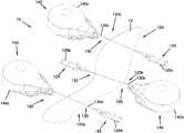
- FIG. 1is a top perspective view of a wound closure system in accordance with the principles of the present disclosure, illustrating multiple stretching elements operably positioned in relation to a wound;
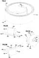
- FIG. 2is a top perspective view of one stretching element of FIG. 1 illustrated alone, the stretching element having a skin anchor and an anchorable tensioning apparatus;
- FIG. 3is an exploded view of the tensioning apparatus of the stretching element of FIG. 2 ;
- FIG. 4is an enlarged top perspective view of a biasing member of the tensioning apparatus of FIG. 3 ;
- FIG. 5Ais a top perspective view of a spool of the tensioning apparatus of FIG. 3 ;
- FIG. 5Bis a bottom perspective view of the spool of FIG. 5A ;
- FIG. 5Cis another bottom perspective view of the spool of FIG. 5A ;
- FIG. 6is an enlarged top perspective view of a base of the tensioning apparatus of FIG. 3 ;
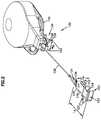
- FIG. 7is a top perspective view of an alternative embodiment of a wound closure system in accordance with the principles of the present disclosure, the wound closure system illustrated in combination with a cross-sectional view of the skin.
- FIG. 1illustrates a wound closure system 10 having features that are examples of inventive aspects disclosed herein.
- the wound closure system 10 illustrated in FIG. 1includes a plurality of stretching elements 120 (each individually indicated as 120 a, 120 b and 120 c ) generally positioned around the periphery of a wound 12 .
- Elements 120 a, 120 b, 120 c, etc.are attached to the skin surrounding wound 12 by mechanical means (e.g., staples).
- Each element 120includes an anchor 125 (each individually indicated as 125 a, 125 b, 125 c ) and an anchorable tensioning apparatus 140 (each individually indicated as 140 a, 140 b, 140 c ).
- Anchors 125 a, 125 b, 125 care connected to anchorable tensioning apparatus 140 a, 140 b, 140 c by a tension line 130 (individually indicated as 130 a, 130 b, 130 c ).
- FIG. 2A single stretching element 120 , having anchor 125 , line 130 and anchorable tensioning apparatus 140 , is illustrated in FIG. 2 .
- inventive aspects of the following disclosurewill be described with reference to only a single stretching element, it being understood that multiple elements can be utilized for the wound closure system within the spirit of the invention, as illustrated in FIG. 1 .
- anchor 125is connected to anchorable tensioning apparatus 140 by tension line 130 , which is fixedly attached to anchor 125 and to tensioning apparatus 140 in a manner as to extend across wound 12 (as illustrated in FIG. 1 ).
- Anchorable tensioning apparatus 140which is attached to skin at the opposite side of the anchor 125 , is adapted to apply tension to line 130 to draw anchor 125 and the tensioning apparatus 140 inwardly toward each other, and, thus, the skin over the wound.
- Anchor 125 and tensioning apparatus 140are positioned to generally linearly move toward each other.
- An inelastic or non-stretchable line 130is preferably used to draw skin anchor 125 and the tensioning apparatus 140 toward wound 12 since the tensioning apparatus 140 is adapted to provide the dynamic force needed for wound closure.
- An elastic line 130can also be used, and may be preferred in some embodiments due to its ability to provide lessened tension and more flexibility.
- an elastic line 130 alone that is fixedly attached to two anchors located on opposite sides of a woundcan be used to provide the dynamic tension on the skin, without the use of a tensioning apparatus.
- tensioning apparatus 140includes a base 160 , a spool 180 that seats on the base 160 , a biasing member 150 that is placed around the spool 180 , a connection rod 190 that extends axially through the tensioning apparatus 140 , and a cover 170 that is placed on the base 160 to enclose the individual components of the tensioning apparatus 140 .
- biasing member 150is adapted to be mounted within tensioning apparatus 140 to provide the dynamic tension force on the skin anchor 125 .
- anchor 125moves toward apparatus 140 and toward wound 12 , reducing the tension on line 130 and creating “slack” on tension line 130 .
- Biasing member 150provides the tension to take up the slack on line 130 .
- the tension force that is applied to each skin anchor 125is usually at least 1 oz. and usually no greater than 64 oz., commonly between 4 and 16 oz.
- biasing member 150is depicted essentially as a spring formed from a coiled-up metal band 151 . Although depicted as a coiled spring in FIGS. 3 and 4 , biasing member 150 may include other structures.
- biasing member 150may include a constant-force spring designed to provide a constant level of tension on line 130 when it is in a loaded state.
- Biasing member 150may alternatively include a nonconstant-force spring designed to provide varying amounts of force on line 130 depending upon how tightly it is wound. As one skilled in the art will appreciate, the force application characteristics of such springs depend upon factors such as the mechanical properties of the springs, the thickness, the diameter, etc.
- biasing membermay also refer to an elastic tension line that is extended across the wound and coupled to two skin anchors on opposite sides of the wound that is used to draw the anchors toward each other and toward the wound.
- the band 151defines an inner hook portion 152 and an outer tab portion 153 .
- the coiled up band 151is positioned around an upper spring mount portion 182 of the spool 180 (see FIGS. 5A-5C ) as will be discussed further below. When positioned as such, a portion of the hook portion 152 of the band 151 is placed within a slot 188 defined on the upper spring mount 182 of the spool 180 .
- the outer tab 153 of the band 151cooperates with the cover 170 of the tensioning apparatus 140 to stay fixedly in a wound orientation.
- the spool 180includes an upper spring mount portion 182 , a lower tension line mount portion 184 , and a main plate 186 separating the two portions.
- all the portions of the spool 180are depicted as integrally formed from one unitary piece. However, it will be appreciated that in other embodiments, the spool may be formed from multiple separate pieces that are coupled together.
- the upper spring mount portion 182has a generally cylindrical shape.
- the upper mount portion 182includes a slot 188 adapted to receive the hook portion 152 of the biasing member 150 as discussed above.
- the spool 180also includes a throughhole 106 for receiving the connection rod 190 used to couple the spool 180 to the base 160 of the tensioning apparatus 140 .
- the lower tension line mount portion 184defines a winding groove 185 .
- the winding groove 185is defined between the main plate 186 and a lower seat plate 183 .
- the lower seat plate 183provides structure for seating the spool 180 into the base 160 of the tensioning apparatus 140 .
- the spool 180also defines a line attachment hole 187 that communicates with the winding groove 185 through a slit 189 defined within the winding groove 185 .
- one end of the tension line 130is fed through the slit 189 into the hole 187 and a knot is tied to secure one end of the tension line 130 to the spool 180 , the knot being large enough that the end of the line 130 will not slip through the slit 189 .
- line 130is wound around the spool 180 within the winding groove 185 .
- Base 160includes a generally circular main body 161 . Defined within the body 161 is an interior cavity 165 shaped to receive the lower seat plate 183 of the spool 180 .
- the base 160includes a hole 164 defined within the interior cavity 165 for receiving the connection rod 190 used to couple the spool 180 to the base 160 .
- the cover 170 of the tensioning apparatus 140generally includes an interior shape configured to fit around the exterior of the base 160 .
- the cover 170includes a main body portion 171 and an elongate snout portion 172 .
- the main body portion 171fits over the main body portion 161 of the base 160 .
- the interior of the cover 170(not shown in the FIGS.) is generally shaped and sized to receive the biasing member 150 .
- the interior of the cover 170includes structure (not shown in the FIGS.) that cooperates with the outer tab portion 153 of the biasing member 150 to keep the biasing member wound up within the cover 170 .
- the snout portion 172 of the cover 170includes a hole for feeding an end of the tension line 130 out of the cover 170 , the other end of the tension line having been attached to the spool 180 located within the cover 170 .
- the front of the snout portion 172includes an extended lip 175 which defines a ramped surface 176 .
- the ramped surface 176is configured to cooperate with a tension line tab 128 of a skin anchor 125 to fixedly mount the cover 170 to a skin anchor 125 . As shown in FIG.
- the ramped surface 176is inserted within a tension line slot 129 defined by the tension line tab 128 of the skin anchor 125 as the tension line tab 128 abuts against the front of the snout 172 .
- the tensioning apparatus 140can be allowed to move with the anchor 125 as the skin is stretched toward the wound 12 .
- the tensioning apparatusis depicted as a unit that is separate from the skin anchor that it is attached to, the tensioning apparatus may include an integrally formed anchoring means adapted to anchor the tensioning apparatus to external skin.
- anchors 125 a, 125 b, 125 care placed around the periphery of wound 12 .
- Each anchor 125is mechanically fastened to the skin, such as by conventional medical skin staples. Suturing can also be used to mechanically attach anchors 125 to the skin.
- Each anchor 125includes a first end 121 , a second opposite end 123 , and a generally rectangular body 124 defined between the first end 121 and the second end 123 .
- the anchor 125includes two skin-penetrating barbs 122 proximate the first end 121 for securement to the skin.
- the barbs 122preferably have a bearing surface with a large enough width perpendicular to the direction of the tension so that the barbs 122 do not cut through the skin when pulled toward the wound 12 in tension. In this manner, as the barbs 122 move in toward the wound, the skin moves with the barbs 122 .
- the barbs 122can be bent at an angle A B less than about 90 degrees from the skin surface.
- the barbs 122can be bent, preferably, at about a 60-degree angle A B to improve their ability to hold into the skin.
- the edges of the barbs 122are sharp to make it easy to penetrate the skin upon insertion.
- Two pairs of indentations, generally indicated at 126are formed on opposite sides of the body 124 of the anchors to help guide where mechanical attachment, such as staples 102 , are to be placed.
- Two pairs of tabs 127 extending out from the opposing sides of the body 124are adapted to abut against the staples 102 to pull the skin toward wound 12 .
- the guiding indentations 126are located forward of the tabs 127 , as anchor 125 is pulled in toward wound 12 , the tabs 127 eventually abut against the staples 102 after initial stretching of the skin around the wound area is achieved.
- the tension line tab 128defines the tension line slot 129 formed at the first end 121 of the anchor 125 for receiving tension line 130 .
- the tension line slot 129is formed with a wide lead-in area to make it easy to receive tension line 130 .
- the tension line slot 129may be sized such that tension line 130 is “snapped-in” past the narrowest point of the slot 129 to prevent the line from accidentally being pulled out.
- anchor 125includes a length L A .
- the barbs 122include a penetration depth D P .
- the inner edges of the barbs 122are spaced apart a distance of W B .
- the dimensions, L A , D P , W B , and A Bcan be varied according to desired skin anchor performance in different parts of the human body and for different types and ages of skin.
- Anchors with example configuration 1are preferably retained by two conventional regular size medical skin staples (5.7 mm ⁇ 3.9 mm).
- Anchors with example configuration 2are preferably retained by two wide size medical skin staples (6.9 mm ⁇ 3.9 mm).
- the anchor 125is formed from stainless steel sheet such as 302 or 316 containing 8 to 14% nickel content. It will be appreciated that the anchors can be stamped with a progressive die, wire EDM-cut, shaped from metal, shaped from wire, injection molded, or made by other suitable methods. The anchors can also be manufactured from other metals such as titanium.
- the barbs of the skin anchors described abovecould optionally include a hollow portion and an exit hole or aperture adapted to be exposed to the undersurface of the skin once the barb penetrates the skin.
- a medicinal componentsuch as anesthesia (such as “Lidocaine”) or an anti-bacterial material, may be applied through the hole and thus to the skin. Any such medicinal component may be provided by a continuous source, such as by being connected to an IV drip, or be applied when the anchor is attached to the skin. In this manner, the medicinal component can be supplied around wound area 12 through skin punctures that have been created by the barbs of the skin anchors.
- tension line 130 of stretching element 120is illustrated as being coupled to anchor 125 across wound 12 .
- Suitable examples for tension line 130include nylon or polypropylene line, suture material, string, a cable, a wire, or other similar item.
- Line 130should be sufficiently flexible and bendable to allow attachment to anchor 125 .
- tension line 130is conventional suture material.
- One preferred line 130is made from nylon and has a tensile strength of about 6 lbs to 10 lbs.
- Tension line 130preferably includes a thread diameter of about 0.5 mm to 0.6 mm.
- the stretching element 120may instead utilize a line 130 that includes elastic material to provide the dynamic tension on skin anchors 125 .
- This elastic linemay also be referred to as a biasing member that provides the tension needed to pull the anchors toward each other and the wound.
- an inelastic linecan be utilized to draw skin anchors 125 toward wound 12 since the tensioning apparatus is adapted to provide the dynamic force needed for wound closure.
- An elastic linecan also be used in addition to a separate tensioning apparatus.
- the skin anchors 125are placed at the opposing sides of a generally linear wound (see FIG. 1 for wound 12 ). After penetrating the skin by pressing the skin engagement barbs 122 of the anchors 125 into the skin, skin anchors 125 may then be further coupled to the skin with the use of, for example, staples 102 .
- the two pairs of indentations 126 defined on the body 124 of skin anchor 125serve as target areas for placement of the staples 102 .
- the tensioning mechanism 140may be assembled with the spool 180 fitting into the base 160 .
- the free end of the line 130is guided out of the snout portion 172 of the cover 170 .
- the biasing member 150is placed on top of the spool 180 , and the cover 170 is mounted on top of the base 160 enclosing the tensioning apparatus 140 .
- a loopis tied at the free end of the line 130 that is fed out of the snout portion 172 of the cover 170 .
- the loopis placed around the tension line tab 128 of the anchor 125 on one side of the wound.
- the tensioning apparatus 140may be pulled across the wound and attached to the anchor at the opposite side of the wound, with the biasing member 150 in a wound-up orientation.
- the wound-up biasing member 150 and hence the spool 180keeps line 130 taut.
- one or more stretching elementsmay be utilized as part of the wound closure system.
- the tensioning apparatus 140may be easily removed from the anchor 125 by holding the line 130 and pulling the tensioning apparatus back away from the anchor to which it is attached.
- skin anchors 225can be placed under the dermis 11 .
- the edges of a wound, such as wound 12would be undermined and then the skin anchors 225 would be inserted between the muscle layer 13 and the subcutaneous fat layer 15 .
- a line 230 from a tensioning apparatus 240(line 230 and tensioning apparatus 240 including features similar to line 130 and tensioning apparatus 140 described above, respectively) would be attached to the skin anchors 225 .
- the tensioning apparatusmay include a rigid conduit 261 through which line 230 may pass, the conduit 261 running from a snout portion 272 of a cover 270 of the tensioning apparatus 240 to the middle of the wound 12 .
- the rigid conduit 261may be similar to a force guide tube disclosed in U.S. Pat. No. 7,455,681, the disclosure of which is incorporated herein in its entirety.
- the rigid conduit 261provides structural support for the line 230 and allows the tensioning apparatus 240 to be positioned at a remote location from the wound 12 .
- the rigid conduitprovides a way to concentrate the pulling force of the tensioning apparatus 240 into a single point at the center of the wound 12 .
- the sub-dermal skin anchors 225may be made from any suitable material and may include features similar to skin anchors 125 .
- a preferred designis to have the skin anchor 225 made from stainless steel and having four skin engagement barbs 222 bent at an angle, such as 60 degrees.
- the physicianwould undermine the skin along the edge of the wound 12 .
- the subcutaneous fat layer 15would be spread from the muscle layer 13 and the skin anchor 225 would be inserted therebetween.
- the skin engagement barbs 222would then engage into the subcutaneous fat 15 and the dermis 11 .
- the skin engagement barbs 222are preferably angled so that as more force is applied to the tension line 230 , the anchors 225 are pulled further into the dermis 11 .
- the skin engagement barbscan be configured to pivot.
- the barbscould be configured such that the barbs would go from a flat position to an angled position via a pivoting structure such as a hinge.
- the skin engagement barbsWhen first inserted into the skin, the skin engagement barbs would be flat or parallel to the surface of the skin anchors and as the anchors are pulled toward the wound by the tensioning apparatus 240 , the barbs would pivot up and start penetrating the subcutaneous fat layer 15 and the dermis 11 .
- An advantage of this designwould be that it would not be necessary to spread the subcutaneous fat layer 15 from the muscle layer 13 as the skin anchors would be easy to slide in between the two layers.
- the skin engagement barbsWhen tension is applied to the tension line 230 , the skin engagement barbs would pivot until a stop position is encountered. This stopping position could be provided at such a point that an angle of 60 degrees or a similar angle from parallel is achieved. The skin engagement barbs would then dig into the dermis and start stretching the skin as force is applied to the tension line 230 .
- the skin anchorscould be made from an absorbable material, that is, a material that is absorbed by body fluids.
- an absorbable materialthat is, a material that is absorbed by body fluids.
- the wound closure system 110 utilizing sub-dermal skin anchors 225can be used with a linear wound closure system such as one described in the present disclosure or could be used with a radial wound closure system such as one described in the pending patent application U.S. Pat. No. 7,455,681.
- a linear wound closure systemsuch as one described in the present disclosure
- a radial wound closure systemsuch as one described in the pending patent application U.S. Pat. No. 7,455,681.
- the line 230 coming out of the tensioning apparatus 240would be split into two ends, each end being coupled to opposing skin anchors 225 to draw the skin anchors toward each other.
- a single line in the form of a loopcan be coupled to anchors placed around the wound as described in further detail in U.S. Pat. No. 7,455,681.
- the wound closure systemmay be used to stretch the skin for purposes other than for wound closure.
- One such example use of the wound closure systemis directed to improving the cosmetic effects of male-pattern baldness.
- the skin anchorsmay be placed on the human scalp such that the tension line extends across the so called “bald spot.”
- the tensioning apparatus or an elastic tension line, for examplethen may be used to gradually draw the skin anchors toward each other to stretch the skin with the hair follicles surrounding the bald spot to eventually reduce the size of the bald spot.
Landscapes
- Health & Medical Sciences (AREA)
- Surgery (AREA)
- Life Sciences & Earth Sciences (AREA)
- Animal Behavior & Ethology (AREA)
- Medical Informatics (AREA)
- Veterinary Medicine (AREA)
- Nuclear Medicine, Radiotherapy & Molecular Imaging (AREA)
- Engineering & Computer Science (AREA)
- Biomedical Technology (AREA)
- Heart & Thoracic Surgery (AREA)
- Public Health (AREA)
- Molecular Biology (AREA)
- General Health & Medical Sciences (AREA)
- Rheumatology (AREA)
- Dermatology (AREA)
- Pathology (AREA)
- Oral & Maxillofacial Surgery (AREA)
- Surgical Instruments (AREA)
Abstract
Description
| TABLE 1 |
| Anchors (unless otherwise specified, all dimensions are in inches) |
| LA | DP | WB | AB | |
| Configuration 1 | 0.739 | 0.158 | 0.186 | 60° |
| Configuration 2 | 0.607 | 0.115 | 0.206 | 60° |
Claims (13)
Priority Applications (1)
| Application Number | Priority Date | Filing Date | Title |
|---|---|---|---|
| US15/426,376US10893856B2 (en) | 2004-11-04 | 2017-02-07 | Wound closure product |
Applications Claiming Priority (4)
| Application Number | Priority Date | Filing Date | Title |
|---|---|---|---|
| US10/982,509US7686829B2 (en) | 2004-11-04 | 2004-11-04 | Wound closure product |
| US12/750,353US8864796B2 (en) | 2004-11-04 | 2010-03-30 | Wound closure product |
| US14/511,416US9597079B2 (en) | 2004-11-04 | 2014-10-10 | Wound closure product |
| US15/426,376US10893856B2 (en) | 2004-11-04 | 2017-02-07 | Wound closure product |
Related Parent Applications (1)
| Application Number | Title | Priority Date | Filing Date |
|---|---|---|---|
| US14/511,416ContinuationUS9597079B2 (en) | 2004-11-04 | 2014-10-10 | Wound closure product |
Publications (2)
| Publication Number | Publication Date |
|---|---|
| US20170238932A1 US20170238932A1 (en) | 2017-08-24 |
| US10893856B2true US10893856B2 (en) | 2021-01-19 |
Family
ID=35745999
Family Applications (4)
| Application Number | Title | Priority Date | Filing Date |
|---|---|---|---|
| US10/982,509Active2027-03-14US7686829B2 (en) | 2004-11-04 | 2004-11-04 | Wound closure product |
| US12/750,353Expired - LifetimeUS8864796B2 (en) | 2004-11-04 | 2010-03-30 | Wound closure product |
| US14/511,416Expired - LifetimeUS9597079B2 (en) | 2004-11-04 | 2014-10-10 | Wound closure product |
| US15/426,376Active2026-03-28US10893856B2 (en) | 2004-11-04 | 2017-02-07 | Wound closure product |
Family Applications Before (3)
| Application Number | Title | Priority Date | Filing Date |
|---|---|---|---|
| US10/982,509Active2027-03-14US7686829B2 (en) | 2004-11-04 | 2004-11-04 | Wound closure product |
| US12/750,353Expired - LifetimeUS8864796B2 (en) | 2004-11-04 | 2010-03-30 | Wound closure product |
| US14/511,416Expired - LifetimeUS9597079B2 (en) | 2004-11-04 | 2014-10-10 | Wound closure product |
Country Status (2)
| Country | Link |
|---|---|
| US (4) | US7686829B2 (en) |
| WO (1) | WO2006052438A1 (en) |
Families Citing this family (33)
| Publication number | Priority date | Publication date | Assignee | Title |
|---|---|---|---|---|
| US7455681B2 (en)* | 2004-09-13 | 2008-11-25 | Wound Care Technologies, Llc | Wound closure product |
| US7686829B2 (en) | 2004-11-04 | 2010-03-30 | Wound Care Technologies, Inc. | Wound closure product |
| US7862582B2 (en)* | 2006-05-02 | 2011-01-04 | Ethicon Endo-Surgery, Inc. | Suture management |
| WO2008043044A2 (en)* | 2006-10-04 | 2008-04-10 | Ndo Surgical, Inc. | Devices and methods for endoluminal gastric restriction tissue manipulation, and drug delivery |
| US20090275980A1 (en)* | 2008-05-01 | 2009-11-05 | Zeiner Mark S | Method and apparatus for the formation of tissue folds |
| US8968355B2 (en)* | 2008-08-04 | 2015-03-03 | Covidien Lp | Articulating surgical device |
| DE102009036165A1 (en)* | 2009-07-28 | 2011-02-03 | Karl Storz Gmbh & Co. Kg | Device for stretching tissue areas |
| US10166021B2 (en) | 2010-07-19 | 2019-01-01 | Wound Care Technologies, Inc. | Wound closure system |
| US9687220B2 (en) | 2012-09-21 | 2017-06-27 | University Of Tennessee Research Foundation | Device for securing an object to a subject and wound closure |
| WO2014116281A1 (en) | 2013-01-25 | 2014-07-31 | Patenaude Bart | Atraumatic wound care and closure system |
| US20150051530A1 (en)* | 2013-08-18 | 2015-02-19 | Insightra Medical Inc. | Designs for wound support apparatus |
| CN103654893B (en)* | 2013-12-27 | 2015-12-16 | 甘肃锦东生物科技有限公司 | Medical adjustable wound stitching instrument |
| US9662112B2 (en)* | 2014-02-10 | 2017-05-30 | Alan E. Nash | System for closing a wound |
| US9662100B2 (en) | 2015-05-27 | 2017-05-30 | Ethicon, Inc. | Tissue wound closure device and applicator instrument |
| US10399755B2 (en) | 2015-06-09 | 2019-09-03 | Foot Innovations, Llc | Modular swiveling strap tie system |
| US20160361062A1 (en) | 2015-06-09 | 2016-12-15 | Foot Innovations, Llc | Strap tie system |
| US9345483B1 (en) | 2015-06-09 | 2016-05-24 | Foot Innovations, Llc | Strap tie system |
| US10583228B2 (en) | 2015-07-28 | 2020-03-10 | J&M Shuler Medical, Inc. | Sub-atmospheric wound therapy systems and methods |
| US10786248B2 (en) | 2016-01-11 | 2020-09-29 | Ethicon. Inc. | Intra dermal tissue fixation device |
| CN109069155B (en)* | 2016-03-01 | 2022-06-24 | 基托泰克医疗股份有限公司 | Microstructure-based systems, devices, and methods for wound closure |
| US10874395B2 (en) | 2016-05-20 | 2020-12-29 | Nifco Inc. | Closure device |
| WO2018132708A1 (en) | 2017-01-12 | 2018-07-19 | Tc1 Llc | Percutaneous driveline anchor devices and methods of use |
| US10894114B2 (en) | 2017-01-12 | 2021-01-19 | Tc1 Llc | Driveline bone anchors and methods of use |
| WO2018144461A1 (en)* | 2017-01-31 | 2018-08-09 | The Board Of Regents Of The University Of Oklahoma | Animal wound model and methods of use |
| CN112165961A (en) | 2018-04-02 | 2021-01-01 | Ic外科公司 | Negative pressure pump and related methods |
| CN110432943B (en)* | 2019-06-28 | 2020-06-05 | 中国人民解放军陆军军医大学第一附属医院 | Skin anastomat |
| US11160917B2 (en) | 2020-01-22 | 2021-11-02 | J&M Shuler Medical Inc. | Negative pressure wound therapy barrier |
| US11986613B2 (en) | 2020-02-19 | 2024-05-21 | Kitotech Medical, Inc. | Microstructure systems and methods for pain treatment |
| CN111407344B (en)* | 2020-04-16 | 2021-02-23 | 中国人民解放军联勤保障部队第九八〇医院 | Adjustable skin stretching device for intracutaneous use |
| CN111728655B (en)* | 2020-07-24 | 2020-12-25 | 魏姝玥 | Adaptive skin stretching system |
| TWI777827B (en)* | 2021-10-22 | 2022-09-11 | 健樂師生醫股份有限公司 | medical fixation system |
| US11957346B2 (en) | 2022-02-18 | 2024-04-16 | Kitotech Medical, Inc. | Force modulating deep skin staples and instruments |
| CN117100347B (en)* | 2023-10-24 | 2024-03-01 | 泓欣科创(北京)科技有限公司 | Wound closure device |
Citations (66)
| Publication number | Priority date | Publication date | Assignee | Title |
|---|---|---|---|---|
| US114750A (en) | 1871-05-16 | Improvement in sticking or adhesive plasters | ||
| US363538A (en) | 1887-05-24 | Suegical | ||
| US2421193A (en) | 1943-08-02 | 1947-05-27 | Cleveland Clinic Foundation | Surgical dressing |
| US3402716A (en) | 1964-01-30 | 1968-09-24 | Surgical Devices | Adhesive strip suture |
| US3559652A (en) | 1968-08-05 | 1971-02-02 | Minnesota Mining & Mfg | Method of adhesively repairing body tissue with alkoxyalkyl 2-cyanoacrylate |
| US3650274A (en)* | 1970-10-20 | 1972-03-21 | Ethicon Inc | Retention suture bridge |
| US3825010A (en) | 1973-04-23 | 1974-07-23 | Donald B Mc | Surgical apparatus for closing wounds |
| FR2268504A1 (en) | 1974-04-25 | 1975-11-21 | Torre Robert | Closing cutaneous wounds of surgical or accident origin - with self-adhesive side strips joined by transverse rapid fastening material |
| US3959960A (en)* | 1975-03-12 | 1976-06-01 | Santos Manuel V | Tensioning, twisting and cutting device for sutures |
| US4646731A (en) | 1985-05-20 | 1987-03-03 | Brower Arthur B | Self adhesive suture and bandage |
| US4742826A (en) | 1986-04-07 | 1988-05-10 | Mclorg Anthony B | Cicatrisive strip with bias |
| US4825866A (en) | 1987-08-27 | 1989-05-02 | Robert Pierce | Wound closure device |
| US4901938A (en)* | 1988-11-21 | 1990-02-20 | Cantley Donald G | Electrical cord retractor |
| US5108433A (en)* | 1989-08-18 | 1992-04-28 | Minnesota Mining And Manufacturing Company | Tensioning means for prosthetic devices |
| US5127412A (en) | 1990-03-14 | 1992-07-07 | Cosmetto Aristodeme J | Skin tensioning |
| EP0531742A1 (en) | 1991-08-15 | 1993-03-17 | United States Surgical Corporation | Hollow body implants |
| US5234462A (en)* | 1991-08-29 | 1993-08-10 | Tufts University | Method and kit for accelerating the closing of open skin wounds |
| US5330489A (en) | 1992-10-09 | 1994-07-19 | United States Surgical Corporation | Sternum closure buckle |
| US5356412A (en) | 1992-10-09 | 1994-10-18 | United States Surgical Corporation | Sternum buckle with rotational engagement and method of closure |
| US5411222A (en)* | 1993-09-23 | 1995-05-02 | Trw Vehicle Safety Systems Limited | Seat belt retractor with tension controller |
| US5422957A (en)* | 1994-01-18 | 1995-06-06 | Cummins; Robert C. | Cable take-up for earphones |
| US5433648A (en)* | 1994-01-07 | 1995-07-18 | Frydman; Larry G. | Rotatable closure device for brassieres and hats |
| US5462542A (en) | 1994-01-24 | 1995-10-31 | United States Surgical Corporation | Sternum buckle with serrated strap |
| WO1995028886A1 (en) | 1994-04-21 | 1995-11-02 | Medchem Products, Inc. | Skin stretching device |
| US5486196A (en)* | 1992-02-13 | 1996-01-23 | Medchem Products, Inc. | Apparatus for the closure of wide skin defects by stretching of skin |
| US5507775A (en) | 1994-01-21 | 1996-04-16 | Progressive Surgical Products Inc. | Tissue expansion and approximation device |
| US5556428A (en)* | 1993-09-29 | 1996-09-17 | Shah; Mrugesh K. | Apparatus and method for promoting growth and repair of soft tissue |
| US5582585A (en)* | 1995-09-25 | 1996-12-10 | Nash-Morgan; Leonora E. | Disposable elastic neck and facial wrinkle gathering device |
| US5649960A (en)* | 1995-02-03 | 1997-07-22 | Pavletic; Michael M. | Apparatus and method for accelerating the stretching of skin |
| US5746192A (en)* | 1996-12-23 | 1998-05-05 | Gissel; Edward B. | Automatic bow retention device |
| US5762281A (en)* | 1997-02-18 | 1998-06-09 | Foley; Michael | Automatically loading cord winder apparatus and method |
| US5769893A (en) | 1993-09-29 | 1998-06-23 | Shah; Mrugesh K. | Apparatus and method for promoting growth and repair of soft tissue |
| US5843123A (en) | 1994-10-06 | 1998-12-01 | Theratechnologies Inc. | Cutaneous harness for sutureless wound closing |
| US5893879A (en)* | 1992-02-13 | 1999-04-13 | Medchem Products, Inc. | Apparatus for the closure of wide skin defects by stretching of skin |
| WO1999035974A1 (en) | 1998-01-19 | 1999-07-22 | Wisebands Ltd. | A suture tightening device for closing wounds and a method for its use |
| US5968097A (en) | 1996-12-20 | 1999-10-19 | Mxm | Elastic device for extending living tissue and having large capacity for elongation |
| US5980473A (en) | 1997-04-08 | 1999-11-09 | Barnes-Jewish Hospital | Surgical apparatus for determining ligament and tendon tension |
| US6120525A (en)* | 1999-07-14 | 2000-09-19 | Westcott; Mitchell S. | Skin tensioning device |
| US6182335B1 (en)* | 1998-01-06 | 2001-02-06 | Idego, Inc. | Clothing protective device |
| US6199785B1 (en)* | 1999-09-28 | 2001-03-13 | Edward C. Paugh | Ratchet mechanism for a reel |
| US6213421B1 (en)* | 1997-03-04 | 2001-04-10 | Contiweiss Weissenfela Gmbh & Co. Kg | Tensioning device |
| US6241747B1 (en) | 1993-05-03 | 2001-06-05 | Quill Medical, Inc. | Barbed Bodily tissue connector |
| US6254624B1 (en)* | 1998-10-06 | 2001-07-03 | Progressive Surgical Products | External tissue expansion device for breast reconstruction, male pattern baldness and removal of nevi and keloids |
| US20010018592A1 (en) | 1999-03-01 | 2001-08-30 | Laurent Schaller | Bridge clip tissue connector apparatus and methods |
| US20010047181A1 (en) | 1999-03-01 | 2001-11-29 | Liem Ho | Tissue connector apparatus with cable release |
| US6421044B2 (en)* | 1998-04-29 | 2002-07-16 | Micron Technology, Inc. | Peripheral input device with a retractable cord |
| US20030073979A1 (en)* | 2001-10-15 | 2003-04-17 | Wendy Naimark | Medical device for delivering patches |
| US20030092969A1 (en)* | 2001-05-09 | 2003-05-15 | O'malley Michael T. | Clinical and surgical system and method for moving and stretching plastic tissue |
| US6599310B2 (en) | 2001-06-29 | 2003-07-29 | Quill Medical, Inc. | Suture method |
| US20030149447A1 (en) | 2002-02-01 | 2003-08-07 | Morency Steven David | Barbed surgical suture |
| US20030163160A1 (en)* | 2000-05-10 | 2003-08-28 | O'malley Michael T | System and method for moving and stretching plastic tissue |
| US6613059B2 (en) | 1999-03-01 | 2003-09-02 | Coalescent Surgical, Inc. | Tissue connector apparatus and methods |
| US6619353B1 (en)* | 1999-08-20 | 2003-09-16 | Jong Gil Kim | Chain for tire |
| WO2005002452A1 (en) | 2003-06-27 | 2005-01-13 | Garvin Dennis D | Device for sutureless wound closure |
| WO2005016153A1 (en) | 2003-07-07 | 2005-02-24 | Intradrug Development Ab | Method and expander system for skin tissue expansion |
| US6871812B1 (en)* | 2004-01-20 | 2005-03-29 | Wen-Han Chang | Multi-stages retractable coiling cord device |
| US20050081339A1 (en)* | 2003-10-21 | 2005-04-21 | Toshiki Sakabayashi | Shoestring tying apparatus |
| US20050085851A1 (en)* | 2003-10-15 | 2005-04-21 | William Fiehler | Tissue puncture closure device with automatic tamping |
| US20050131430A1 (en) | 2003-12-12 | 2005-06-16 | Arvik Enterprises, Llc | Suturing device |
| US20050184186A1 (en)* | 2004-02-20 | 2005-08-25 | Chung Haap Tsoi | Retractable cable winder |
| US20050192599A1 (en) | 2004-02-13 | 2005-09-01 | Demarais Denise M. | Methods for reducing hollow organ volume |
| US20060058842A1 (en)* | 2004-09-13 | 2006-03-16 | Wilke Robert C | Wound closure product |
| US20060095076A1 (en) | 2004-11-04 | 2006-05-04 | Elliott Daniel M | Wound closure product |
| US7056331B2 (en) | 2001-06-29 | 2006-06-06 | Quill Medical, Inc. | Suture method |
| US7208006B2 (en)* | 2002-03-01 | 2007-04-24 | Wilhelm Fleischmann | Process and instrument for stretching tissue of skin |
| US20080097483A1 (en) | 2006-05-02 | 2008-04-24 | Ethicon Endo-Surgery, Inc. | Suture management |
- 2004
- 2004-11-04USUS10/982,509patent/US7686829B2/enactiveActive
- 2005
- 2005-10-24WOPCT/US2005/038394patent/WO2006052438A1/enactiveApplication Filing
- 2010
- 2010-03-30USUS12/750,353patent/US8864796B2/ennot_activeExpired - Lifetime
- 2014
- 2014-10-10USUS14/511,416patent/US9597079B2/ennot_activeExpired - Lifetime
- 2017
- 2017-02-07USUS15/426,376patent/US10893856B2/enactiveActive
Patent Citations (76)
| Publication number | Priority date | Publication date | Assignee | Title |
|---|---|---|---|---|
| US114750A (en) | 1871-05-16 | Improvement in sticking or adhesive plasters | ||
| US363538A (en) | 1887-05-24 | Suegical | ||
| US2421193A (en) | 1943-08-02 | 1947-05-27 | Cleveland Clinic Foundation | Surgical dressing |
| US3402716A (en) | 1964-01-30 | 1968-09-24 | Surgical Devices | Adhesive strip suture |
| US3559652A (en) | 1968-08-05 | 1971-02-02 | Minnesota Mining & Mfg | Method of adhesively repairing body tissue with alkoxyalkyl 2-cyanoacrylate |
| US3650274A (en)* | 1970-10-20 | 1972-03-21 | Ethicon Inc | Retention suture bridge |
| US3825010A (en) | 1973-04-23 | 1974-07-23 | Donald B Mc | Surgical apparatus for closing wounds |
| FR2268504A1 (en) | 1974-04-25 | 1975-11-21 | Torre Robert | Closing cutaneous wounds of surgical or accident origin - with self-adhesive side strips joined by transverse rapid fastening material |
| US3959960A (en)* | 1975-03-12 | 1976-06-01 | Santos Manuel V | Tensioning, twisting and cutting device for sutures |
| US4646731A (en) | 1985-05-20 | 1987-03-03 | Brower Arthur B | Self adhesive suture and bandage |
| US4742826A (en) | 1986-04-07 | 1988-05-10 | Mclorg Anthony B | Cicatrisive strip with bias |
| US4825866A (en) | 1987-08-27 | 1989-05-02 | Robert Pierce | Wound closure device |
| US4901938A (en)* | 1988-11-21 | 1990-02-20 | Cantley Donald G | Electrical cord retractor |
| US5108433A (en)* | 1989-08-18 | 1992-04-28 | Minnesota Mining And Manufacturing Company | Tensioning means for prosthetic devices |
| US5127412A (en) | 1990-03-14 | 1992-07-07 | Cosmetto Aristodeme J | Skin tensioning |
| EP0531742A1 (en) | 1991-08-15 | 1993-03-17 | United States Surgical Corporation | Hollow body implants |
| US5234462A (en)* | 1991-08-29 | 1993-08-10 | Tufts University | Method and kit for accelerating the closing of open skin wounds |
| US5893879A (en)* | 1992-02-13 | 1999-04-13 | Medchem Products, Inc. | Apparatus for the closure of wide skin defects by stretching of skin |
| US5486196A (en)* | 1992-02-13 | 1996-01-23 | Medchem Products, Inc. | Apparatus for the closure of wide skin defects by stretching of skin |
| US5356412A (en) | 1992-10-09 | 1994-10-18 | United States Surgical Corporation | Sternum buckle with rotational engagement and method of closure |
| US5330489A (en) | 1992-10-09 | 1994-07-19 | United States Surgical Corporation | Sternum closure buckle |
| US6241747B1 (en) | 1993-05-03 | 2001-06-05 | Quill Medical, Inc. | Barbed Bodily tissue connector |
| US5411222A (en)* | 1993-09-23 | 1995-05-02 | Trw Vehicle Safety Systems Limited | Seat belt retractor with tension controller |
| US5769893A (en) | 1993-09-29 | 1998-06-23 | Shah; Mrugesh K. | Apparatus and method for promoting growth and repair of soft tissue |
| US5556428A (en)* | 1993-09-29 | 1996-09-17 | Shah; Mrugesh K. | Apparatus and method for promoting growth and repair of soft tissue |
| US5433648A (en)* | 1994-01-07 | 1995-07-18 | Frydman; Larry G. | Rotatable closure device for brassieres and hats |
| US5422957A (en)* | 1994-01-18 | 1995-06-06 | Cummins; Robert C. | Cable take-up for earphones |
| US5507775A (en) | 1994-01-21 | 1996-04-16 | Progressive Surgical Products Inc. | Tissue expansion and approximation device |
| US5618310A (en) | 1994-01-21 | 1997-04-08 | Progressive Surgical Products, Inc. | Tissue, expansion and approximation device |
| US5462542A (en) | 1994-01-24 | 1995-10-31 | United States Surgical Corporation | Sternum buckle with serrated strap |
| WO1995028886A1 (en) | 1994-04-21 | 1995-11-02 | Medchem Products, Inc. | Skin stretching device |
| US5843123A (en) | 1994-10-06 | 1998-12-01 | Theratechnologies Inc. | Cutaneous harness for sutureless wound closing |
| US5649960A (en)* | 1995-02-03 | 1997-07-22 | Pavletic; Michael M. | Apparatus and method for accelerating the stretching of skin |
| US5582585A (en)* | 1995-09-25 | 1996-12-10 | Nash-Morgan; Leonora E. | Disposable elastic neck and facial wrinkle gathering device |
| US5968097A (en) | 1996-12-20 | 1999-10-19 | Mxm | Elastic device for extending living tissue and having large capacity for elongation |
| US5746192A (en)* | 1996-12-23 | 1998-05-05 | Gissel; Edward B. | Automatic bow retention device |
| US5762281A (en)* | 1997-02-18 | 1998-06-09 | Foley; Michael | Automatically loading cord winder apparatus and method |
| US6213421B1 (en)* | 1997-03-04 | 2001-04-10 | Contiweiss Weissenfela Gmbh & Co. Kg | Tensioning device |
| US5980473A (en) | 1997-04-08 | 1999-11-09 | Barnes-Jewish Hospital | Surgical apparatus for determining ligament and tendon tension |
| US6182335B1 (en)* | 1998-01-06 | 2001-02-06 | Idego, Inc. | Clothing protective device |
| WO1999035974A1 (en) | 1998-01-19 | 1999-07-22 | Wisebands Ltd. | A suture tightening device for closing wounds and a method for its use |
| US6471715B1 (en)* | 1998-01-19 | 2002-10-29 | Wisebands Ltd | Suture tightening device for closing wounds and method for its use |
| US6421044B2 (en)* | 1998-04-29 | 2002-07-16 | Micron Technology, Inc. | Peripheral input device with a retractable cord |
| US6254624B1 (en)* | 1998-10-06 | 2001-07-03 | Progressive Surgical Products | External tissue expansion device for breast reconstruction, male pattern baldness and removal of nevi and keloids |
| US6960221B2 (en) | 1999-03-01 | 2005-11-01 | Medtronic, Inc. | Tissue connector apparatus with cable release |
| US20010018592A1 (en) | 1999-03-01 | 2001-08-30 | Laurent Schaller | Bridge clip tissue connector apparatus and methods |
| US20010047181A1 (en) | 1999-03-01 | 2001-11-29 | Liem Ho | Tissue connector apparatus with cable release |
| US6613059B2 (en) | 1999-03-01 | 2003-09-02 | Coalescent Surgical, Inc. | Tissue connector apparatus and methods |
| US6120525A (en)* | 1999-07-14 | 2000-09-19 | Westcott; Mitchell S. | Skin tensioning device |
| US6619353B1 (en)* | 1999-08-20 | 2003-09-16 | Jong Gil Kim | Chain for tire |
| US6199785B1 (en)* | 1999-09-28 | 2001-03-13 | Edward C. Paugh | Ratchet mechanism for a reel |
| US20030163160A1 (en)* | 2000-05-10 | 2003-08-28 | O'malley Michael T | System and method for moving and stretching plastic tissue |
| US20030092969A1 (en)* | 2001-05-09 | 2003-05-15 | O'malley Michael T. | Clinical and surgical system and method for moving and stretching plastic tissue |
| US6599310B2 (en) | 2001-06-29 | 2003-07-29 | Quill Medical, Inc. | Suture method |
| US7056331B2 (en) | 2001-06-29 | 2006-06-06 | Quill Medical, Inc. | Suture method |
| US20030073979A1 (en)* | 2001-10-15 | 2003-04-17 | Wendy Naimark | Medical device for delivering patches |
| US20030149447A1 (en) | 2002-02-01 | 2003-08-07 | Morency Steven David | Barbed surgical suture |
| US7208006B2 (en)* | 2002-03-01 | 2007-04-24 | Wilhelm Fleischmann | Process and instrument for stretching tissue of skin |
| WO2005002452A1 (en) | 2003-06-27 | 2005-01-13 | Garvin Dennis D | Device for sutureless wound closure |
| WO2005016153A1 (en) | 2003-07-07 | 2005-02-24 | Intradrug Development Ab | Method and expander system for skin tissue expansion |
| US20050085851A1 (en)* | 2003-10-15 | 2005-04-21 | William Fiehler | Tissue puncture closure device with automatic tamping |
| US20050081339A1 (en)* | 2003-10-21 | 2005-04-21 | Toshiki Sakabayashi | Shoestring tying apparatus |
| US20050131430A1 (en) | 2003-12-12 | 2005-06-16 | Arvik Enterprises, Llc | Suturing device |
| US6871812B1 (en)* | 2004-01-20 | 2005-03-29 | Wen-Han Chang | Multi-stages retractable coiling cord device |
| US20050192599A1 (en) | 2004-02-13 | 2005-09-01 | Demarais Denise M. | Methods for reducing hollow organ volume |
| US20050184186A1 (en)* | 2004-02-20 | 2005-08-25 | Chung Haap Tsoi | Retractable cable winder |
| US20060058842A1 (en)* | 2004-09-13 | 2006-03-16 | Wilke Robert C | Wound closure product |
| US7455681B2 (en) | 2004-09-13 | 2008-11-25 | Wound Care Technologies, Llc | Wound closure product |
| US20090018579A1 (en) | 2004-09-13 | 2009-01-15 | Wound Care Technologies, Llc | Wound closure product |
| US20090018578A1 (en) | 2004-09-13 | 2009-01-15 | Wound Care Technologies, Llc, | Wound closure product |
| US7927352B2 (en) | 2004-09-13 | 2011-04-19 | Wound Care Technologies, Llc | Method of closing a wound using a wound closure product |
| US7972362B2 (en) | 2004-09-13 | 2011-07-05 | Wound Care Technologies, Llc | Wound closure product |
| US20060095076A1 (en) | 2004-11-04 | 2006-05-04 | Elliott Daniel M | Wound closure product |
| US7686829B2 (en) | 2004-11-04 | 2010-03-30 | Wound Care Technologies, Inc. | Wound closure product |
| US20100185236A1 (en) | 2004-11-04 | 2010-07-22 | Wound Care Technologies, Llc | Wound closure product |
| US20080097483A1 (en) | 2006-05-02 | 2008-04-24 | Ethicon Endo-Surgery, Inc. | Suture management |
Non-Patent Citations (15)
| Title |
|---|
| "History of Wound Care," http://www.proxiderm.com/html/intro2.html, 3 pages (date printed: Jul. 28, 2004). |
| "Proxiderm Procedure," http://www.proxiderm.com/html/intro3.html, 2 pages (date printed: Jul. 28, 2004). |
| Canica® design brochure, "Canica Wound Closure System," © Canica Design, 2004 (5 pages). |
| Galil, K. et al., "Effect of N-Butyl-2-Cyanoacrylate (Histoacryl Blue) on the Healing of Skin Wounds," J. Canad. Dent. Assn., No. 7, pp. 565-569 (1984). |
| Gibson, T. et al., "Directional Variation in Extensibility of Human Skin in Vivo," J. Biomechanics, vol. 2, pp. 201-204 (1969). |
| Gibson, T. et al., "The Mobile Micro-Architecture of Dermal Collagen," Brit. J. Surg.., vol. 52, No. 10, pp. 764-770 (Oct. 1965). |
| Hirshowitz, B. et al., "A Skin-Stretching Device for the Harnessing of the Viscoelastic Properties of Skin," Plastic and Reconstructive Surgery, vol. 92 No. 2, pp. 260-270 (Aug. 1993). |
| Liang, M. et al., "Presuturing-A New Technique for Closing Large Skin Defects: Clinical and Experimental Studies," Plastic and Reconstructive Surgery, vol. 81, No. 5, pp. 694-702 (May 1988). |
| Liang, M. et al., "Presuturing—A New Technique for Closing Large Skin Defects: Clinical and Experimental Studies," Plastic and Reconstructive Surgery, vol. 81, No. 5, pp. 694-702 (May 1988). |
| Mustoe, T. et al., "Physical, Biomechanical, Histologic, and Biochemical Effects of Rapid versus Conventional Tissue Expansion," Plastic and Reconstructive Surgery, vol. 83, No. 4, pp. 687-691 (Apr. 1989). |
| Progressive Surgical Products Inc. brochure, "External Tissue Expansion," Proxiderm™ , Copyright 1997 (3 pages). |
| Radovan, C., "Tissue Expansion in Soft-Tissue Reconstruction," Plastic and Reconstructive Surgery, vol. 74, No. 4, pp. 482-490 (Oct. 1984). |
| Schessel, Eli S. et al., "External Constant Tension Expansion of Soft Tissue for the Treatment of Ulceration of the Foot and Ankle," Journal of Foot & Ankle Surgery, vol. 39, No. 5, pp. 321-328, Sep./Oct. 2000. |
| Stark, H. et al., "Directional Variations in the Extensibility of Human Skin," British Journal of Plastic Surgery, vol. 30, pp. 105-114 (1977). |
| Topical Hyperbaric Oxygen™ Therapy, "Healing Difficult Wounds," http://www.gwrmedical.com, 3 pages (date printed: Apr. 28, 2004). |
Also Published As
| Publication number | Publication date |
|---|---|
| US20060095076A1 (en) | 2006-05-04 |
| US8864796B2 (en) | 2014-10-21 |
| US20170238932A1 (en) | 2017-08-24 |
| WO2006052438A1 (en) | 2006-05-18 |
| US9597079B2 (en) | 2017-03-21 |
| US20100185236A1 (en) | 2010-07-22 |
| US20150157322A1 (en) | 2015-06-11 |
| US7686829B2 (en) | 2010-03-30 |
Similar Documents
| Publication | Publication Date | Title |
|---|---|---|
| US10893856B2 (en) | Wound closure product | |
| US10925596B2 (en) | Wound closure product | |
| US11944291B2 (en) | Wound closure system | |
| EP2214564B1 (en) | Implantable purse string suture tensioning device | |
| US8945181B2 (en) | Suture retention devices and associated products and methods | |
| US20030092969A1 (en) | Clinical and surgical system and method for moving and stretching plastic tissue | |
| CA2551895A1 (en) | System and method for moving and stretching plastic tissue | |
| AU2021218168A1 (en) | Locking suture construct | |
| RU2718320C2 (en) | Skin stretching device | |
| US9687220B2 (en) | Device for securing an object to a subject and wound closure | |
| CN115192108A (en) | Wound closure system and method | |
| CN218045231U (en) | Wound closure system | |
| HK1111330A1 (en) | Button anchor system for moving tissue |
Legal Events
| Date | Code | Title | Description |
|---|---|---|---|
| AS | Assignment | Owner name:WOUND CARE TECHNOLOGIES, LLC, MINNESOTA Free format text:ASSIGNMENT OF ASSIGNORS INTEREST;ASSIGNORS:WILKE, ROBERT C.;ELLIOTT, DANIEL M.;HOEDEMAN, GEORGE M.;AND OTHERS;SIGNING DATES FROM 20041221 TO 20041229;REEL/FRAME:044043/0082 Owner name:WOUND CARE TECHNOLOGIES, INC., MINNESOTA Free format text:ASSIGNMENT OF ASSIGNORS INTEREST;ASSIGNOR:WOUND CARE TECHNOLOGIES, LLC;REEL/FRAME:044043/0230 Effective date:20110809 | |
| STPP | Information on status: patent application and granting procedure in general | Free format text:NON FINAL ACTION MAILED | |
| STPP | Information on status: patent application and granting procedure in general | Free format text:RESPONSE TO NON-FINAL OFFICE ACTION ENTERED AND FORWARDED TO EXAMINER | |
| STPP | Information on status: patent application and granting procedure in general | Free format text:FINAL REJECTION MAILED | |
| STPP | Information on status: patent application and granting procedure in general | Free format text:NON FINAL ACTION MAILED | |
| STPP | Information on status: patent application and granting procedure in general | Free format text:RESPONSE TO NON-FINAL OFFICE ACTION ENTERED AND FORWARDED TO EXAMINER | |
| STPP | Information on status: patent application and granting procedure in general | Free format text:NOTICE OF ALLOWANCE MAILED -- APPLICATION RECEIVED IN OFFICE OF PUBLICATIONS | |
| STPP | Information on status: patent application and granting procedure in general | Free format text:PUBLICATIONS -- ISSUE FEE PAYMENT VERIFIED | |
| STCF | Information on status: patent grant | Free format text:PATENTED CASE | |
| MAFP | Maintenance fee payment | Free format text:PAYMENT OF MAINTENANCE FEE, 4TH YEAR, LARGE ENTITY (ORIGINAL EVENT CODE: M1551); ENTITY STATUS OF PATENT OWNER: LARGE ENTITY Year of fee payment:4 |